JP5478932B2 - Power slide device - Google Patents
Power slide deviceDownload PDFInfo
- Publication number
- JP5478932B2 JP5478932B2JP2009103311AJP2009103311AJP5478932B2JP 5478932 B2JP5478932 B2JP 5478932B2JP 2009103311 AJP2009103311 AJP 2009103311AJP 2009103311 AJP2009103311 AJP 2009103311AJP 5478932 B2JP5478932 B2JP 5478932B2
- Authority
- JP
- Japan
- Prior art keywords
- pair
- tensioner
- drive unit
- outer casing
- cables
- Prior art date
- Legal status (The legal status is an assumption and is not a legal conclusion. Google has not performed a legal analysis and makes no representation as to the accuracy of the status listed.)
- Expired - Fee Related
Links
Images


Classifications
- E—FIXED CONSTRUCTIONS
- E05—LOCKS; KEYS; WINDOW OR DOOR FITTINGS; SAFES
- E05F—DEVICES FOR MOVING WINGS INTO OPEN OR CLOSED POSITION; CHECKS FOR WINGS; WING FITTINGS NOT OTHERWISE PROVIDED FOR, CONCERNED WITH THE FUNCTIONING OF THE WING
- E05F15/00—Power-operated mechanisms for wings
- E05F15/60—Power-operated mechanisms for wings using electrical actuators
- E05F15/603—Power-operated mechanisms for wings using electrical actuators using rotary electromotors
- E05F15/632—Power-operated mechanisms for wings using electrical actuators using rotary electromotors for horizontally-sliding wings
- E05F15/643—Power-operated mechanisms for wings using electrical actuators using rotary electromotors for horizontally-sliding wings operated by flexible elongated pulling elements, e.g. belts, chains or cables
- E05F15/646—Power-operated mechanisms for wings using electrical actuators using rotary electromotors for horizontally-sliding wings operated by flexible elongated pulling elements, e.g. belts, chains or cables allowing or involving a secondary movement of the wing, e.g. rotational or transversal
- E—FIXED CONSTRUCTIONS
- E05—LOCKS; KEYS; WINDOW OR DOOR FITTINGS; SAFES
- E05F—DEVICES FOR MOVING WINGS INTO OPEN OR CLOSED POSITION; CHECKS FOR WINGS; WING FITTINGS NOT OTHERWISE PROVIDED FOR, CONCERNED WITH THE FUNCTIONING OF THE WING
- E05F15/00—Power-operated mechanisms for wings
- E05F15/60—Power-operated mechanisms for wings using electrical actuators
- E05F15/603—Power-operated mechanisms for wings using electrical actuators using rotary electromotors
- E05F15/632—Power-operated mechanisms for wings using electrical actuators using rotary electromotors for horizontally-sliding wings
- E05F15/655—Power-operated mechanisms for wings using electrical actuators using rotary electromotors for horizontally-sliding wings specially adapted for vehicle wings
- E05F15/662—Motor units therefor, e.g. geared motors
- E—FIXED CONSTRUCTIONS
- E05—LOCKS; KEYS; WINDOW OR DOOR FITTINGS; SAFES
- E05D—HINGES OR SUSPENSION DEVICES FOR DOORS, WINDOWS OR WINGS
- E05D15/00—Suspension arrangements for wings
- E05D15/06—Suspension arrangements for wings for wings sliding horizontally more or less in their own plane
- E05D15/10—Suspension arrangements for wings for wings sliding horizontally more or less in their own plane movable out of one plane into a second parallel plane
- E05D15/1042—Suspension arrangements for wings for wings sliding horizontally more or less in their own plane movable out of one plane into a second parallel plane with transversely moving carriage
- E05D2015/1055—Suspension arrangements for wings for wings sliding horizontally more or less in their own plane movable out of one plane into a second parallel plane with transversely moving carriage with slanted or curved track sections or cams
Landscapes
- Closing And Opening Devices For Wings, And Checks For Wings (AREA)
- Power-Operated Mechanisms For Wings (AREA)
Description
Translated fromJapanese本発明は、車両に設けられるスライドドアを自動的に開閉するパワースライド装置に関する。 The present invention relates to a power slide device that automatically opens and closes a slide door provided in a vehicle.
従来から、ワゴンタイプやワンボックスタイプの車両では、車両前後方向に開閉移動するスライドドアを車体側部に設けることにより、車両側方からの乗降や荷物の積み下ろしを容易に行えるようにしている。車体側部における乗降口後方の上下中央部には、車両前後方向に延びる直線部と、直線部の車両前方側の端部から車室内側へ向けて湾曲する引き込み部とを備えるセンタレール(ガイドレール)が固定されている。一方、スライドドアにおける車両後方側の上下中央部には、センタレールに移動自在に装着されるセンタアームが回動自在に支持されている。スライドドアは、このセンタアームがセンタレールに沿って車両前後方向に移動することによりスライド式に開閉される。つまり、センタアームがセンタレールの直線部に案内されるとスライドドアは開状態となり、センタアームがセンタレールの引き込み部に案内されてセンタアームがスライドドアに対して回動されると、スライドドアは車室内側に引き込まれて閉状態となる。 Conventionally, in a wagon type or one-box type vehicle, a slide door that opens and closes in the vehicle front-rear direction is provided on the side of the vehicle body so that passengers can easily get on and off and load and unload luggage. A center rail (guide) includes a linear portion extending in the vehicle front-rear direction and a pull-in portion that curves toward the vehicle interior side from the vehicle front side end portion of the linear portion at the upper and lower central portion behind the entrance / exit on the vehicle body side portion. Rail) is fixed. On the other hand, a center arm that is movably mounted on a center rail is rotatably supported at an upper and lower central portion of the sliding door on the vehicle rear side. The sliding door is opened and closed in a sliding manner as the center arm moves in the vehicle longitudinal direction along the center rail. That is, when the center arm is guided to the straight portion of the center rail, the slide door is opened, and when the center arm is guided to the retracting portion of the center rail and the center arm is rotated with respect to the slide door, the slide door is opened. Is pulled into the passenger compartment and is closed.
このスライドドアの開閉操作を容易にするために、車両には駆動ユニットによりスライドドアを自動的に開閉するようにしたパワースライド装置(自動開閉装置)が搭載されている。パワースライド装置としては、駆動ユニットによりケーブルを牽引することでスライドドアを自動的に開閉するケーブル式のものが多く用いられている。また、このケーブル式のパワースライド装置には、駆動ユニットを車体側部に搭載した車体内蔵型と、駆動ユニットをスライドドアに搭載したドア内蔵型とがある。車体内蔵型のパワースライド装置では、駆動ユニットのドラムに巻き掛けられた一対のケーブルが、センタレールの両端側にそれぞれ配置される一対のプーリユニットを介してセンタアームへ配索されている。そして、駆動ユニットのドラムにより一方のケーブルを巻き取るとともに他方のケーブルを送り出すことで、スライドドアがケーブルに牽引されて自動開閉動作するようになっている。この車体内蔵型のパワースライド装置には、駆動ユニットと一対のプーリユニットとの間でケーブルが挿通される一対のアウタケーシングが設けられて、アウタケーシングによりケーブルが案内されている。 In order to facilitate the opening / closing operation of the sliding door, the vehicle is equipped with a power slide device (automatic opening / closing device) that automatically opens and closes the sliding door by a drive unit. As a power slide device, a cable type device that automatically opens and closes a slide door by pulling a cable by a drive unit is often used. The cable-type power slide device includes a vehicle body built-in type in which a drive unit is mounted on the side of the vehicle body and a door built-in type in which the drive unit is mounted on a slide door. In the power slide device with a built-in vehicle body, a pair of cables wound around the drum of the drive unit is routed to the center arm via a pair of pulley units respectively disposed on both ends of the center rail. And by winding up one cable with the drum of a drive unit and sending out the other cable, the sliding door is pulled by the cable and is automatically opened and closed. The vehicle body built-in type power slide device is provided with a pair of outer casings through which cables are inserted between the drive unit and the pair of pulley units, and the cables are guided by the outer casings.
また、駆動ユニットには、一対のケーブルに所定の張力を付与するための一対のテンショナ機構を備えたものがある。テンショナ機構には、アウタケーシングの一端に装着されたエンドキャップをコイルばねにより付勢して、ケーブルの全長に対するアウタケーシング長の比率を大きくすることで、ケーブルに所定の張力を付与するようにしたアウタプッシュ式のテンショナ機構と、ケーブルが巻き掛けられるプーリをコイルばねにより付勢して、ドラムとエンドキャップとの間のケーブル長を大きくすることで、ケーブルに所定の張力を付与するようにしたインナプル式のテンショナ機構とがある。このテンショナ機構により、ケーブルに所定の張力が付与されることで、ケーブルの緩みが抑制されてパワースライド装置が円滑に作動されるようになっている。 Some drive units include a pair of tensioner mechanisms for applying a predetermined tension to the pair of cables. In the tensioner mechanism, the end cap attached to one end of the outer casing is urged by a coil spring to increase the ratio of the outer casing length to the total length of the cable, thereby applying a predetermined tension to the cable. The outer push type tensioner mechanism and the pulley around which the cable is wound are energized by a coil spring to increase the cable length between the drum and the end cap, thereby applying a predetermined tension to the cable. There is an inner type tensioner mechanism. By applying a predetermined tension to the cable by this tensioner mechanism, loosening of the cable is suppressed and the power slide device is operated smoothly.
ところで、パワースライド装置を車両に組み付ける際には、駆動ユニットから引き出された一対のケーブルの一端をセンタアームにおいて容易に係止可能とするために、アウタケーシングからのケーブルの引出し量を十分に確保する必要がある。そのため、例えば、特許文献1(図3)に示されるパワースライド装置では、アウタプッシュ式のテンショナ機構に十分なストロークを持たせ、テンショナケースの内部に組み付けられたストッパによりエンドキャップをコイルばねの付勢力に抗して後退させた位置に保持して、ケーブルの全長に対するアウタケーシング長の比率を小さくすることで、アウタケーシングからのケーブルの引き出し量を確保している。そして、ケーブルを配索した後には、ストッパによるエンドキャップの保持を解除するとともに、ストッパによりテンショナ機構のストロークを規制して、エンドキャップが過度に後退することでケーブルに緩みが生じることを抑制するようにしている。 By the way, when assembling the power slide device to the vehicle, a sufficient amount of cable drawing from the outer casing is ensured so that one end of the pair of cables drawn out from the drive unit can be easily locked in the center arm. There is a need to. Therefore, for example, in the power slide device shown in Patent Document 1 (FIG. 3), the outer push type tensioner mechanism has a sufficient stroke, and the end cap is attached to the coil spring by a stopper assembled inside the tensioner case. The amount of the cable drawn from the outer casing is secured by reducing the ratio of the length of the outer casing to the total length of the cable while maintaining the position retracted against the force. After the cable is routed, the end cap is held by the stopper, and the stroke of the tensioner mechanism is restricted by the stopper to prevent the end cap from retreating excessively to cause the cable to loosen. I am doing so.
しかしながら、特許文献1に示されるパワースライド装置においては、テンショナケースの内部にストッパを組み付けるようにしているため、テンショナケースにはストッパを収容するスペースが必要となり、駆動ユニットが大型化することとなる。 However, in the power slide device shown in
また、駆動ユニットの小型化のために、一方のテンショナケースのみにストッパを組み付けることも考えられるが、その場合には、車両の左右両側に設けられる一対のパワースライド装置において駆動ユニットを共通化することが困難となることがある。例えば、駆動ユニットを一方のプーリユニットに近接して配置するようにした一対のパワースライド装置において駆動ユニットを共通化する場合には、一方のパワースライド装置ではストッパが組み付けられたテンショナケースが一方のプーリユニット側に配置され、他方のパワースライド装置ではストッパが組み付けられたテンショナケースが他方のプーリユニット側に配置される。このとき、一方のパワースライド装置では、ストッパが組み付けられたテンショナケースと一方のプーリユニットとの距離が近く、アウタケーシングがストレート配索されるため、アウタケーシングに十分なストロークを持たせることができず、ストッパが機能しないこととなる。 In order to reduce the size of the drive unit, it is conceivable to attach a stopper only to one tensioner case. In that case, however, the drive unit is shared by a pair of power slide devices provided on the left and right sides of the vehicle. Can be difficult. For example, when a drive unit is shared in a pair of power slide devices in which the drive unit is arranged close to one pulley unit, the tensioner case with a stopper assembled in one power slide device A tensioner case, which is disposed on the pulley unit side and has a stopper assembled in the other power slide device, is disposed on the other pulley unit side. At this time, in one power slide device, the distance between the tensioner case assembled with the stopper and the one pulley unit is short, and the outer casing is routed straight, so that the outer casing can have a sufficient stroke. Therefore, the stopper will not function.
本発明の目的は、駆動ユニットを小型化するとともに、車両の左右両側に設けられる一対のパワースライド装置において駆動ユニットを共通化可能とすることにある。 An object of the present invention is to reduce the size of a drive unit and to make the drive unit common in a pair of power slide devices provided on both the left and right sides of a vehicle.
本発明のパワースライド装置は、車体に搭載される駆動ユニットにより一対のケーブルを駆動することで、前記車体に固定されるガイドレールに沿ってスライドドアを自動的に開閉するパワースライド装置であって、前記スライドドアに回動自在に支持され、前記ガイドレールに移動自在に装着されるセンタアームと、前記ガイドレールの両端側にそれぞれ配置され、前記駆動ユニットから配索された一対の前記ケーブルを前記センタアームへ案内する一対のプーリユニットと、前記駆動ユニットに設けられ、一対の前記ケーブルに張力を付与する一対のテンショナ機構と、一対の前記テンショナ機構がそれぞれ収容される一対のテンショナケースと、一対の前記テンショナケースと一対の前記プーリユニットとの間に設けられ、一対の前記ケーブルが挿通される一対のアウタケーシングと、一対の前記テンショナケースのうち一方の前記テンショナケースの外部に着脱自在に組み付けられ、一方の前記アウタケーシングの一端を移動自在とする解放状態と、一方の前記アウタケーシングの一端の移動を規制する規制状態とに操作されるストッパユニットと、他方の前記アウタケーシングを他方の前記テンショナケースに組み付けるケーシングキャップと、を有し、一対の前記ケーブルは、前記駆動ユニットから相互にほぼ直交する方向に引き出され、前記ストッパユニットを介して前記一方のテンショナケースに組み付けられた一方の前記アウタケーシングと、前記ケーシングキャップを介して前記他方のテンショナケースに組み付けられた他方の前記アウタケーシングとが、前記一対のテンショナケースの外部で相互に交差した状態にあり、前記ストッパユニットは、一方の前記テンショナケースと、前記一対のアウタケーシングが相互に交差する個所との間に配置されていることを特徴とする。A power slide device of the present invention is a power slide device that automatically opens and closes a slide door along a guide rail fixed to the vehicle body by driving a pair of cables by a drive unit mounted on the vehicle body. A center arm rotatably supported by the slide door and movably mounted on the guide rail, and a pair of cables routed from the drive unit respectively disposed on both ends of the guide rail. A pair of pulley units for guiding to the center arm; a pair of tensioner mechanisms provided on the drive unit for applying tension to the pair of cables; and a pair of tensioner cases each housing the pair of tensioner mechanisms; Provided between the pair of tensioner cases and the pair of pulley units; A pair of outer casings through which a cable is inserted, and a released state in which one end of one of the outer casings is detachably assembled to the outside of one of the pair of tensioner cases.possess a stopper unit to be operated and regulated state for restricting the movement of one end of the outer casing, and the casing cap assembling the other of said outer casing to the other of said tensioner case,a pair of said cable, said drive One outer casing pulled out from the unit in a direction substantially perpendicular to each other and assembled to the one tensioner case via the stopper unit, and the other assembled to the other tensioner case via the casing cap The outer casing of the front In a state in which cross each other outside of the pair of the tensioner case, the stopper unit includes a one of the tensioner case, the pair of outer casing and features that youhave placed between the point intersecting with each other To do.
本発明のパワースライド装置は、前記解放状態のもとでの一方の前記アウタケーシングの一端は、前記規制状態のもとでの一方の前記アウタケーシングの一端よりも一方の前記テンショナ機構側へ移動自在であることを特徴とする。 In the power slide device of the present invention, one end of the one outer casing under the released state moves to one tensioner mechanism side rather than one end of the one outer casing under the restricted state. It is characterized by being free.
本発明のパワースライド装置は、一方の前記アウタケーシングは、他方の前記アウタケーシングよりも長寸に形成されており、一方の前記アウタケーシングは、前記駆動ユニットと一方の前記プーリユニットとの間でたわみを持たせた状態で配索されており、他方の前記アウタケーシングは、前記駆動ユニットと他方の前記プーリユニットとの間でストレート配索されていることを特徴とする。In the power slide device of the present invention, one of the outer casings is formed to be longer than the other outer casing,and the one outer casing is disposed between the drive unit and the one pulley unit. The outer casing is routed in a state of being bent, and the other outer casing is routed straight between the drive unit and the other pulley unit .
本発明のパワースライド装置は、前記ケーシングキャップは、他方の前記テンショナケースと、前記一対のアウタケーシングが相互に交差する個所との間に配置されていることを特徴とする。The power slide device of the present invention is characterized in that thecasing cap is disposed between the other tensioner case and a location where the pair of outer casings intersect each other .
本発明のパワースライド装置は、一対の前記アウタケーシングは、一対の前記ケーブルが巻き掛けられる前記駆動ユニットのドラムの回転軸方向に相互にずれた状態で、前記駆動ユニットに組み付けられていることを特徴とする。 In the power slide device of the present invention, the pair of outer casings are assembled to the drive unit in a state where they are displaced from each other in the rotation axis direction of the drum of the drive unit around which the pair of cables are wound. Features.
本発明によれば、解放状態と規制状態とに操作されるストッパユニットをテンショナ機構の外部に組み付けるようにしたので、ケーブルの配索時にはケーブルの引き出し量を十分に確保してケーブルをセンタアームに係止する作業を容易に行うことができるとともに、ケーブルの配索完了後にはケーブルの引き出し量を適当な長さに設定してパワースライド装置を円滑に作動させることができる。したがって、従来のように、テンショナ機構に十分なストロークを持たせてケーブルの引き出し量を確保するとともに、ケーブルの配索後にテンショナ機構のストロークを規制するストッパをテンショナケースの内部に装着する必要がないので、駆動ユニットを小型化することが可能となる。また、ストッパユニットを一方のテンショナケースに着脱自在としたので、パワースライド装置のレイアウトに合わせてストッパユニットを他方のテンショナケースに組み替えることで、車両の左右両側に配設される一対のパワースライド装置において駆動ユニットを容易に共通化することができる。 According to the present invention, since the stopper unit operated in the released state and the restricted state is assembled outside the tensioner mechanism, when the cable is routed, a sufficient amount of the cable is secured to secure the cable to the center arm. The locking operation can be easily performed, and after the cable routing is completed, the power slide device can be smoothly operated by setting the cable drawing amount to an appropriate length. Therefore, unlike the conventional case, it is not necessary to provide a sufficient stroke for the tensioner mechanism to secure the cable pull-out amount and to attach a stopper for regulating the stroke of the tensioner mechanism after the cable is installed inside the tensioner case. Therefore, the drive unit can be reduced in size. In addition, since the stopper unit is detachably attached to one tensioner case, a pair of power slide devices disposed on the left and right sides of the vehicle can be obtained by rearranging the stopper unit to the other tensioner case according to the layout of the power slide device. The drive unit can be easily shared.
以下、本発明の実施の形態を図面に基づいて詳細に説明する。 Hereinafter, embodiments of the present invention will be described in detail with reference to the drawings.
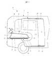
図1に示す車両11はワンボックスタイプの乗用車であり、その車体12の側部には乗降用の開口部13を開閉するための開閉体としてのスライドドア14が設けられている。このスライドドア14は、車体12の側部に固定されたガイドレールとしてのセンタレール15に沿って車両前後方向に移動されることで開口部13を開閉するようになっている。 A
図2に示すように、車体12の側部における開口部後方の上下方向略中央部には、車両前後方向に延びるとともに車室内側に向けて窪む凹部12aが形成されている。センタレール15は、この凹部12a内に配置されている。センタレール15の断面は、車室外側に開口が形成された略方形形状に形成されている。また、センタレール15は、車体12の側部に沿って車両前後方向に延びる直線部15aと、直線部15aの車両前方側の端部から車室内方側へ向けて湾曲する引き込み部15bとを備えている。 As shown in FIG. 2, a
一方、スライドドア14の車両後方側の上下方向略中央部にはローラユニット16が設けられている。ローラユニット16は、スライドドア14のドアパネル(図示省略)に固定されたブラケット17に回動軸18を介して取り付けられるセンタアーム19を備えている。センタアーム19は、軸方向を車両上下方向に向けて配置された回動軸18により、スライドドア14に対して水平方向に回動自在に支持されている。センタアーム19には、センタレール15へ向けて屈曲するローラ装着部19aが設けられており、ローラ装着部19aに走行ローラ20と一対の案内ローラ21とが回転自在に取り付けられている。これら走行ローラ20および案内ローラ21がセンタレール15内に配置されて、走行ローラ20がセンタレール15の車両下方向の面を走行するとともに案内ローラ21がセンタレール15の車幅方向の両面に支持されて案内されることで、センタアーム19はセンタレール15に移動自在に装着されている。 On the other hand, a
このセンタアーム19がセンタレール15に沿って車両前後方向に移動することにより、スライドドア14は車体12の側部に沿ってスライド式に開閉される。つまり、センタアーム19がセンタレール15の直線部15aに案内されるとスライドドア14は開状態となり、センタアーム19がセンタレール15の引き込み部15bに案内されると、スライドドア14は車体12の側面と面一となるように車室内方側へ引き込まれて閉状態となる。センタアーム19がセンタレール15の引き込み部15bを移動する際には、センタアーム19が回動軸18を軸心としてスライドドア14に対して回動されることにより、スライドドア14が車体12の側部とほぼ平行を保った状態で車両前後方向に移動されるようになっている。 When the
なお、図1に示すように、スライドドア14の車両前方側の上下端部に設けられたローラユニット22,23は、車体12における開口部13の上下縁部に固定されたアッパレール24、ロワーレール25にそれぞれ移動自在に装着されている。これにより、スライドドア14は計3カ所において車体12に支持されている。また、図2に示すように、車両11の美観性の向上のために、車体12の側部にはセンタレール15を覆うカバー部材26が装着されている。 As shown in FIG. 1, the
この車両11には、スライドドア14を自動的に開閉するために、車両用自動開閉装置としてのパワースライド装置30が設けられている。パワースライド装置30は、閉側ケーブル31と開側ケーブル32とを備える所謂ケーブル式の開閉装置となっている。また、パワースライド装置30は、一対のケーブル31,32を駆動するための駆動源としての駆動ユニット(PSDモータ)33を車体側部に搭載した車体内蔵型の開閉装置である。駆動ユニット33は、車体側部における車両後方側の端部つまりセンタレール15の開側(センタレール15における車両後方側)端部付近において、センタレール15よりも車両上方側に配置されている。 The
センタレール15の両端側には、駆動ユニット33から配索された一対のケーブル31,32をセンタアーム19へ案内する一対のプーリユニット34,35がそれぞれ設けられている。駆動ユニット33から車両前方側に引き出された閉側ケーブル31は、センタレール15の閉側(センタレール15における車両前方側)端部付近に配置される閉側プーリユニット34の図示しないプーリにより配索方向が変換されてセンタレール15に沿って車両後方側に配索され、その他端部31aがセンタアーム19に係止されている。また、駆動ユニット33から車両下方側に引き出された開側ケーブル32は、センタレール15の開側端部付近に配置される開側プーリユニット35の図示しないプーリにより配索方向が変換されてセンタレール15に沿って車両前方側に配索され、その他端部32aがセンタアーム19に係止されている。 A pair of
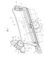
駆動ユニット33と一対のプーリユニット34,35との間には、ケーブル31,32を案内するための閉側アウタケーシング36および開側アウタケーシング37がそれぞれ設けられている。アウタケーシング36,37は可撓性を有する樹脂材料によりチューブ状に形成されている。閉側アウタケーシング36は、一端が駆動ユニット33に組み付けられるとともに他端が閉側プーリユニット34に組み付けられて、駆動ユニット33と閉側プーリユニット34との間でたるみを持たせた状態で配置されている。また、開側アウタケーシング37は、一端が駆動ユニット33に組み付けられるとともに他端が開側プーリユニット35に組み付けられて、駆動ユニット33と開側プーリユニット35との間でほぼ直線状に配置されている。 Between the
すなわち、駆動ユニット33を開側プーリユニット35に近接して配置したので、駆動ユニット33と閉側プーリユニット34との距離が遠く、閉側アウタケーシング36は開側アウタケーシング37よりも長寸に形成されるため、閉側アウタケーシング36を駆動ユニット33と閉側プーリユニット34との間でたわみを持たせた状態で配索することが可能となっている。一方、駆動ユニット33と開側プーリユニット35との距離が近く、開側アウタケーシング37をたわみを持たせた状態で配索することが困難であるため、開側アウタケーシング37は駆動ユニット33と開側プーリユニット35との間でストレート配索されている。また、一対のアウタケーシング36,37を駆動ユニット33から相互にほぼ直交する方向に交差した状態で引き出すことにより、駆動ユニット33を開側プーリユニット35に近接して配置した状態で、駆動ユニット33と一対のプーリユニット34,35との間で一対のアウタケーシング36,37を配索可能となっている。ケーブル31,32は、これらアウタケーシング36,37内に挿通されてアウタケーシング36,37に沿って案内されるようになっている。 That is, since the
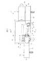
図3は駆動ユニットの内部構造の一部を示す背面図であり、後述するドラムカバー46を取り外した状態を示している。図4は図2における矢印A方向から見た駆動ユニットの矢視図であり、図5は図4におけるB−B線に沿う断面図である。 FIG. 3 is a rear view showing a part of the internal structure of the drive unit, and shows a state in which a
図3に示すように、駆動ユニット33は、モータ本体41とモータ本体41の出力により一対のケーブル31,32を駆動する駆動部42とを備えている。モータ本体41としては、モータシャフト43を正逆両方向に回転可能なブラシ付き直流モータ等の電動モータが用いられる。 As shown in FIG. 3, the
図5に示すように、モータ本体41が取り付けられる駆動部42のモータフレーム44は、モータシャフト43の軸方向と直交する方向(図5において上下方向)に開口する略円筒形状に形成されている。モータフレーム44には、モータフレーム44の軸方向一端側(車室外方側)の開口部を覆うクラッチカバー45と、モータフレーム44の軸方向他端側(車室内方側)の開口部を覆うドラムカバー46とが取り付けられている。これらクラッチカバー45およびドラムカバー46によりモータフレーム44の開口部が閉塞されている。また、図3に示すように、モータフレーム44の軸方向略中央部には、モータ本体41が取り付けられるモータ接続部47が一体に形成されており、モータ接続部47はモータ本体41側つまりモータフレーム44の開口側と直交する方向に開口している。モータ本体41は、このモータ接続部47の開口側の端面に固定されて、モータシャフト43の軸方向先端側をモータフレーム44内に突出させている。 As shown in FIG. 5, the
モータフレーム44内に突出されたモータシャフト43の軸方向先端側の外周面には、ウォーム43aが一体に形成されている。モータフレーム44内には、モータフレーム44の軸方向略中央部に位置して、ウォーム43aと噛み合うウォームホイール48が収容されている。このウォームホイール48の軸心には、モータフレーム44内に軸受49,50によってモータフレーム44に対して回転自在に支持された出力軸51が挿通されており、ウォームホイール48は出力軸51により当該出力軸51に対して相対回転自在に支持されている。 A
モータ本体41の出力は、これらウォーム43aおよびウォームホイール48からなるウォームギヤ機構(減速機構)により減速されて、クラッチ機構52を介して出力軸51に伝達される。クラッチ機構52は、モータフレーム44の軸方向一端側に形成されたクラッチ収容部44aに収容されている。スライドドア14が手動により開閉操作されるときには、このクラッチ機構52によりウォームホイール48と出力軸51との間の動力伝達経路が遮断されるようになっている。 The output of the motor
出力軸51の軸方向他端側には、一対のケーブル31,32が巻き掛けられる螺旋状のケーブル溝53aを備えたドラム53が固定されている。ドラム53は、モータフレーム44の軸方向他端側に形成されたドラム収容部44bに収容されている。閉側ケーブル31は、その一端がドラム53の回転軸方向一端に固定されるとともに、ドラム53の回転軸方向一端側のケーブル溝53aに巻き掛けられて、閉側プーリユニット34から離反する方向に引き出されている。一方、開側ケーブル32は、その一端がドラム53の回転軸方向他端に固定されるとともに、ドラム53の回転軸方向他端側のケーブル溝53aに巻き掛けられて、開側プーリユニット35側から離反する方向に引き出されている。つまり、一対のケーブル31,32は、ドラム53の回転軸方向に相互にずれた状態でドラム53から引き出されている。 A
また、一対のケーブル31,32は、その一端から他端へ向けて相互に反対方向にドラム53に巻き掛けられることにより、モータ本体41が作動すると相互に逆向きに駆動されるようになっている。ドラム53が図3において時計回り方向に回転される場合には、閉側ケーブル31がドラム53により巻き取られるとともに開側ケーブル32がドラム53により送り出されることで、スライドドア14が閉側へ牽引されて自動閉動作する。逆に、ドラム53が図3において反時計回り方向に回転される場合には、開側ケーブル32がドラム53により巻き取られるとともに閉側ケーブル31がドラム53により送り出されることで、スライドドア14が開側へ牽引されて自動開動作することとなる。 Further, the pair of
図3に示すように、駆動ユニット33には、ケーブル31,32に所定の張力を付与するためのインナプル式の閉側テンショナ機構55aおよび開側テンショナ機構55bが設けられている。テンショナ機構55a,55bは、対応するケーブル31,32のドラム53からの引き出し位置において、モータフレーム44と一体に形成されたテンショナケース56a,56bにそれぞれ収容されている。このテンショナケース56a,56bは、モータフレーム44の軸方向他端側(車室内方側)に開口する略矩形のケース状となっており、ドラムカバー46と一体に形成されたテンショナカバー57a,57bがテンショナケース56a,56bに取り付けられて、テンショナケース56a,56bの開口部がテンショナカバー57a,57bにより閉塞されている。 As shown in FIG. 3, the
テンショナ機構55a,55bは、対応するアウタケーシング36,37の配索方向とほぼ平行に延びる丸棒状のガイド軸58と、円筒形状に形成されたスライド部59aにおいてガイド軸58に沿って移動自在かつガイド軸58の軸心を中心として回動自在にガイド軸58に装着されるプーリホルダ59とを備えている。プーリホルダ59のホルダ本体部59bには、ドラム53の回転軸つまりドラム53を支持する出力軸51とほぼ平行に配された支軸60により、プーリ61が回転自在に支持されている。ドラム53から引き出されたケーブル31,32は、このプーリ61に巻き掛けられてアウタケーシング36,37へ案内されている。 The
また、テンショナ機構55a,55bには、ガイド軸58のアウタケーシング36,37側の一端部とプーリホルダ59のスライド部59aとの間に、ばね部材としてのコイルばね62が装着されている。このコイルばね62により、プーリホルダ59はアウタケーシング36,37から離反する方向に付勢されている。コイルばね62の付勢力により、プーリ61がアウタケーシング36,37から離反する方向にガイド軸58に沿って移動されると、テンショナケース56a,56b内においてドラム53とアウタケーシング36,37の一端との間のケーブル31,32のケーブル長が長くなるため、ケーブル31,32に所定の張力が付与される。これにより、センタアーム19がセンタレール15の引き込み部15bに案内される等して、駆動ユニット33とセンタアーム19との間で配索されるケーブル31,32のケーブル長が変化しても、テンショナ機構55a,55bによりケーブル31,32の張力が保たれるので、ケーブル31,32に緩みが生じないようになっている。 The
図4に示すように、この一対のテンショナ機構55a,55bは、一対のケーブル31,32のドラム53からの引き出し位置が相互にドラム53の回転軸方向にずれているため、相互にドラム53の回転軸方向にずれて配置されている。すなわち、開側テンショナ機構55bは閉側テンショナ機構55aよりもドラム59の回転軸方向他端側へずれて配置されている。よって、一対のアウタケーシング36,37の一端は、相互にドラム53の回転軸方向にずれた状態で駆動ユニット33のテンショナケース56a,56bに組み付けられるため、一対のアウタケーシング36,37が相互に干渉することが防止されて、アウタケーシング36,37を相互にほぼ直交する方向に交差した状態で駆動ユニット33から引き出すことが可能となっている。 As shown in FIG. 4, the pair of
次に、アウタケーシング36,37の一端をテンショナケース56a,56bに組み付けるための組付構造について説明する。図6はアウタケーシングの組付構造を示す概略斜視図であり、図7は図6に示すアウタケーシングの組付構造の分解斜視図である。 Next, an assembly structure for assembling one end of the
図6に示すように、開側アウタケーシング37は、開側アウタケーシング37の駆動ユニット33側の一端に装着される樹脂製のケーシングキャップ65により、開側テンショナ機構55bのテンショナケース56bに組み付けられている。図7に示すように、ケーシングキャップ65は開側ケーブル32の配索方向に延びる略円筒形状となっており、その軸方向中央部にはケーシングキャップ65の径方向に突出する大径部65aが設けられている。ケーシングキャップ65は、その軸方向他端側(開側プーリユニット35側)から開側アウタケーシング37の一端が圧入された状態で、ケーシングキャップ65の軸方向他端側を締結部材66に圧入することにより、開側アウタケーシング37の一端に装着されている。このケーシングキャップ65の軸方向一端側(テンショナケース56b側)には、段付き形状に形成された係合部65bが形成されている。 As shown in FIG. 6, the open-side
テンショナケース56bには、テンショナケース56bからの開側ケーブル32の引き出し位置において、ケーシングキャップ65が組み付けられる係合溝67が形成されている。係合溝67は、テンショナケース56bの開口側(車室内方側)に開口するとともに、ケーシングキャップ65の係合部65bに係合可能な段付き溝形状となっている。ケーシングキャップ65は、大径部65aをテンショナケース56bの外面に突き当てて、係合部65bをテンショナケース56bの係合溝67に係合させた状態で、テンショナケース56bにテンショナカバー57bが取り付けられることにより、テンショナケース56bに着脱自在に組み付けられている。これにより、開側アウタケーシング37の一端はケーシングキャップ65を介してテンショナケース56bに固定され、開側テンショナ機構55bから配索された開側ケーブル32は、ケーシングキャップ65を介して開側アウタケーシング37に挿通されている。 The
一方、図6に示すように、閉側アウタケーシング36は、閉側アウタケーシング36の駆動ユニット33側の一端に配設されるストッパユニット70を介して、閉側テンショナ機構55aのテンショナケース56aに組み付けられている。ストッパユニット70は、閉側アウタケーシング36の一端に装着される樹脂製のケーシングキャップ71と、ケーシングキャップ71を移動自在に収容するケース部材72と、ケーシングキャップ71をケース部材72に固定するストッパ73とを有している。 On the other hand, as shown in FIG. 6, the closed
図7に示すように、ケーシングキャップ71は閉側ケーブル31の配索方向に延びる略円筒形状となっており、その軸方向中央部にはケーシングキャップ71の径方向に突出する大径部71aが設けられている。ケーシングキャップ71は、その軸方向他端側(閉側プーリユニット34側)から閉側アウタケーシング36の一端が圧入されることにより、閉側アウタケーシング36の一端に装着されている。 As shown in FIG. 7, the
ケース部材72は、閉側ケーブル31の配索方向に延びる略円筒形状のケース本体部72aと、ケース本体部72aの軸方向一端側(テンショナケース56a側)に一体に設けられる係合部72bとを備えている。ケース部材72の係合部72bは、ケーシングキャップ65の係合部65bとほぼ同形状の段付き円筒状に形成されている。 The
ケース部材72のケース本体部72aは、内径がケーシングキャップ71の大径部71aよりも僅かに大径に形成されるとともに、ケース本体部72aの軸方向他端側(閉側プーリユニット34側)に開口されて、内部にケーシングキャップ71がケース本体部72aの軸方向に移動自在に収容されている。ケース本体部72aには、車室内方側(モータフレーム44の軸方向他端側)に開口する一対の挿通孔74と、車室外方側(モータフレーム44の軸方向一端側)に開口する二対の係止孔75,76とが形成されている。一対の挿通孔74は、ケース本体部72aの軸方向に相互に平行に延びるとともに、ケース本体部72aの軸方向と直交する方向(図3における上下方向)に相互に離間して配されている。また、二対の係止孔75,76は、一対の挿通孔74の長手方向両端部に対して車室内外方向に対向しており、一対の挿通孔74の長手方向一端部(テンショナケース56a側の端部)に対向させて一対の係止孔75が配され、一対の挿通孔74の長手方向他端部(閉側プーリユニット34側の端部)に対向させて一対の係止孔76が配されている。 The case
テンショナケース56aには、テンショナケース56aからの閉側ケーブル31の引き出し位置において、ケース部材72が組み付けられる係合溝77が形成されている。係合溝77は、テンショナケース56aの開口側(車室内方側)に開口するとともに、ケース部材72の係合部72bに係合可能な段付き溝形状となっている。ケース部材72は、ケース本体部72aの軸方向一端側の端面をテンショナケース56aの外面に突き当てて、係合部72bをテンショナケース56aの係合溝77に係合させた状態で、テンショナケース56aにテンショナカバー57aが取り付けられることにより、テンショナケース56aの外部に着脱自在に組み付けられている。閉側テンショナ機構55aから配索された閉側ケーブル31は、係合部72bからケース部材72内に挿入されて、ケーシングキャップ71を介して閉側アウタケーシング36に挿通されている。 The
ストッパ73は、金属プレートを略U字状に曲げ加工することにより、車室外方側へ延びる一対の挿入板73aと、一対の挿入板73aにおける車室内方側の端部同士を連結する連結板73bとを備えている。一対の挿入板73aは、ケース部材72の一対の挿入孔74に対応させて、ケース部材72の軸方向に相互に平行に延びるとともに、ケース部材72の軸方向と直交する方向に相互に離間して配されている。また、一対の挿入板73aには、ケース部材72の二対の係止孔75,76に対応させて、一対の挿入板73aの長手方向両端部から車室外方側に突出する二対の脚部78,79が設けられており、ケース部材72の一対の係止孔75に対応させて、一対の挿入板73aの長手方向一端部(テンショナケース56a側の端部)から車室外方側へ一対の脚部78が延び、ケース部材72の一対の係止孔76に対応させて、一対の挿入板73aの長手方向他端部(閉側プーリユニット34側の端部)から車室外方側へ一対の脚部79が延びている。 The
各脚部78,79には、一対の突起80,81がストッパ73の挿入方向(車室内外方向)に相互に離間してそれぞれ形成されており、各脚部78,79の挿入方向先端部(車室外方側の端部)に突起80が設けられ、各脚部78,79の挿入方向基端側(車両内方側)に突起81が設けられている。各突起80,81は、車室内方側に向かうにつれてストッパ73の長手方向内側に向けて突出する楔形状となっている。また、一対の挿入板73aには、一対の脚部79に隣接させて車室内方側に向けて切り欠かれたストッパ溝82が形成されている。各ストッパ溝82は、ストッパ73の挿入方向先端側に開口して、ケーシングキャップ71の大径部71aを挿入方向先端側から挿入可能な形状となっている。 A pair of
このストッパ73は、各挿入板73aがケース部材72の各挿入孔74に挿入されるとともに、各脚部78,79がケース部材72の対応する係止孔75,76に挿入されることにより、ケース部材72のケース本体部72aに組み付けられている。また、ストッパ73は、各脚部78,79が対応する係止孔75,76に挿入されて、各脚部78,79に設けられた一対の突起80,81のうちのいずれか一方がケース本体部72aの外周面に引っ掛けられて係止されることによりケース部材72からの抜けが防止され、突起80によりケース部材72に係止される解放位置と、突起81によりケース部材72に係止される規制位置とに操作されるようになっている。 The
図8(a)は解放状態のもとでのストッパユニットを示す断面図である。図8(b)は規制状態のもとでのストッパユニットを示す断面図であり、図3におけるC−C線に沿う断面図を示している。 FIG. 8A is a sectional view showing the stopper unit in the released state. FIG. 8B is a cross-sectional view showing the stopper unit under a restricted state, and shows a cross-sectional view taken along the line CC in FIG.
図8(a)に示すように、ケーシングキャップ71がケース部材72のケース本体部72aに収容された状態で、ストッパ73がケース本体部72aに組み付けられて解放位置へ操作されると、ストッパユニット70は解放状態となる。この解放状態のもとでは、ケース本体部72a内に配される各脚部78,79との間で、ケーシングキャップ71がケース本体部72aの軸方向に沿って移動自在に組み付けられている。つまり、閉側アウタケーシング36を駆動ユニット33と閉側プーリユニット34との間でたわみを持たせた状態で配索したので、ケーシングキャップ71は、大径部71aの軸方向一端側の端面が各脚部78に当接する後退位置(図8(a)に示す)と、大径部71aの軸方向他端側の端面が各脚部79に当接する前進位置(図8(b)に示す)との間で移動自在となっている。 8A, when the
ケーシングキャップ71をケース本体部72a内で移動させることで、閉側アウタケーシング36の一端が閉側ケーブル31の配索方向に沿って移動することとなり、ストッパユニット70と閉側プーリユニット34との間の閉側アウタケーシング36のアウタケーシング長が変化される。これにより、一対のケーブル31,32の全長に対する一対のアウタケーシング36,37のアウタケーシング長の比率が変化されるため、プーリユニット34,35側におけるアウタケーシング36,37からのケーブル31,32の引き出し量を変化させることが可能となっている。 By moving the
ケーシングキャップ71が前進位置となると、アウタケーシング36,37からのケーブル31,32の引き出し量が適当な長さに設定されるため、ケーブル31,32が過度に緩むことが抑制される。一方、ケーシングキャップ71が後退位置となると、アウタケーシング36,37からのケーブル31,32の引き出し量が、ケーシングキャップ71が後退位置のもとでのケーブル31,32の引き出し量よりもケーシングキャップ71の移動量(前進位置と後退位置との距離)Lだけ全体として大きくなる。したがって、ケーブル31,32の配索の際に、ケーブル31,32の引き出し量を十分に確保することができるので、ケーブル31,32の他端部31a,32aをセンタアーム19に係止する作業を容易に行うことが可能となる。 When the
図8(b)に示すように、ケーシングキャップ71が前進位置に移動された状態で、ストッパ73が解放位置からさらに挿入されて規制位置に操作されると、ストッパユニット70は規制状態となる。この規制状態のもとでは、ケース本体部72a内に配される各挿入板73aのストッパ溝82にケーシングキャップ71の大径部71aが挿通されて、ケーシングキャップ71の移動が規制されており、ケーシングキャップ71が前進位置のもとでストッパ73によりケース部材72に固定されることによって、アウタケーシング36,37からのケーブル31,32の引き出し量が適当な長さに設定された状態で、閉側アウタケーシング36がストッパユニット70を介してテンショナケース56aに固定されるようになっている。したがって、ケーブル31,32にテンショナ機構55a,55bのストローク以上の過度の緩みが生じることがなく、テンショナ機構55a,55bによりケーブル31,32の緩みを抑制してパワースライド装置30を円滑に作動させることが可能となる。 As shown in FIG. 8B, when the
次に、駆動ユニット33とセンタアーム19との間でケーブル31,32を配索する際のストッパユニット70の操作について説明する。 Next, the operation of the
まず、車体12に搭載された駆動ユニット33とプーリユニット34,35との間にアウタケーシング36,37を設けて、駆動ユニット33から引き出されたケーブル31,32をアウタケーシング36,37に沿って案内する。このとき、駆動ユニット33が開側プーリユニット35に近接して配置されることから、開側アウタケーシング37は、一端が駆動ユニット33に固定されるとともに他端が開側プーリユニット35に固定されて、駆動ユニット33と開側プーリユニット35との間でストレート配索される。一方、閉側アウタケーシング37は、一端がストッパユニット70により駆動ユニット33に対して移動自在に組み付けられるとともに、他端が閉側プーリユニット34に固定されて、駆動ユニット33と閉側プーリユニット34との間でたわみを持たせた状態で配索される。つまり、閉側アウタケーシング36の一端に装着されたケーシングキャップ71は、テンショナケース56aに固定されたケース部材72のケース本体部72aに収容され、当該ケース本体部72aに組み付けられて解放位置に操作されたストッパ73により、前進位置と後退位置との間で閉側ケーブル31の配索方向に沿って移動自在となっている。 First, the
このケーシングキャップ71を図8(a)に示す後退位置に移動させると、閉側アウタケーシング36の一端部がケース部材72のケース本体部72a内に引き込まれて、ケース部材72と閉側プーリユニット34との間のアウタケーシング長が小さくなる。これにより、一対のケーブル31,32の全長に対する一対のアウタケーシング36,37のアウタケーシング長の比率が小さくなるので、プーリユニット34,35側においてアウタケーシング36,37からのケーブル31,32の引き出し量が大きくなる。したがって、アウタケーシング36,37からのケーブル31,32の引き出し量を十分に確保することができるので、ケーブル31,32の他端部31a,32aをセンタアーム19に係止する作業を容易に行うことができる。 When the
ケーブル31,32の配索が完了した後には、図8(b)に示すように、ケーシングキャップ71を前進位置に移動させた状態で、ストッパ73をさらに挿入して規制位置に操作することにより、ケーシングキャップ71の大径部71aがストッパ73のストッパ溝82に挿通されて、ケーシングキャップ71の移動が規制される。ケーシングキャップ71が前進位置のもとでは、アウタケーシング36,37からのケーブル31,32の引き出し量が適当な長さに設定されるため、ケーブル31,32にテンショナ機構55a,55bのストローク以上の過度の緩みが生じることがなく、テンショナ機構55a,55bによりケーブル31,32の緩みを抑制してパワースライド装置30を円滑に作動させることが可能となる。 After the
上記においては、車両右側に配設されるパワースライド装置30について説明したが、テンショナケース56aに組み付けられたストッパユニット70をテンショナケース56bに組み替えることで、この駆動ユニット33を車両左側に配設されるパワースライド装置に共通化することができる。すなわち、この駆動ユニット33を車両左側に配設されるパワースライド装置に搭載する場合には、テンショナケース56aが開側プーリユニット側に配置され、テンショナケース56bが閉側プーリユニット側に配置されることとなり、テンショナケース56aと開側プーリユニットとの間で開側アウタケーシングがストレート配索されるため、開側アウタケーシングに十分なストロークを持たせることができず、ストッパユニット70が機能しないこととなる。しかしながら、ストッパユニット70をテンショナケース56aの外部に着脱自在に組み付けるようにしたので、ストッパユニット70をテンショナケース56bに組み替えることで、駆動ユニット33を車両11の左右両側に配設される一対のパワースライド装置30で共通化することが可能となっている。このとき、ストッパユニット70のケース部材72の係合部72aをケーシングキャップ65の係合部65bとほぼ同形状としたので、ストッパユニット70を容易に組み替えることができる。 In the above description, the
このように、閉側アウタケーシング36の一端を移動自在とする解放状態と、閉側アウタケーシング36の一端の移動を規制する規制状態とに操作されるストッパユニット70をテンショナケース56aの外部に着脱自在に組み付けるようにしたので、ケーブル31,32の配索時にはストッパユニット70を解放状態に操作することで、アウタケーシング36,37からのケーブル31,32の引き出し量を十分に確保してケーブル31,32の他端部31a,32aをセンタアーム19に係止する作業を容易に行うことができる。また、ケーブル31,32の配索完了後にはストッパユニット70を規制状態に操作して、アウタケーシング36,37からのケーブル31,32の引き出し量を適当な長さに設定した状態で閉側アウタケーシング36の一端を固定することで、ケーブル31,32にテンショナ機構55a,55bのストローク以上の過度の緩みが生じることがなく、テンショナ機構55a,55bによりケーブル31,32の緩みを抑制してパワースライド装置30を円滑に作動させることが可能となる。したがって、従来のように、テンショナ機構に十分なストロークを持たせてケーブルの引き出し量を確保するとともに、ケーブルの配索後にテンショナ機構のストロークを規制するストッパをテンショナケース内に装着する必要がないので、駆動ユニット33を小型化することが可能となる。 In this way, the
さらに、ストッパユニット70をテンショナケース56aに着脱自在に装着するようにしたので、駆動ユニット33を開側プーリユニット35に近接して配置した場合においても、ストッパユニット70をテンショナケース56bに組み替えることで、車両11の左右両側に設けられる一対のパワースライド装置30において駆動ユニット33を容易に共通化することができる。つまり、ストッパユニット70を一方のテンショナケース56aのみに組み付けるようにして小型化した駆動ユニット33を、一対のパワースライド装置30において共通化することが可能となっている。 Further, since the
本発明は前記実施の形態に限定されるものではなく、その要旨を逸脱しない範囲で種々変更可能であることはもちろんである。例えば、前記実施の形態においては、駆動ユニット33を開側プーリユニット35に近接して配置したが、これに限定されず、駆動ユニット33を閉側プーリユニット34に近接して配置したり、駆動ユニット33をプーリユニット34,35の略中間部に配置したりするようにしても良い。その場合には、駆動ユニット33のレイアウトに合わせてストッパユニット70を組み替えることで、車両11の左右両側に配設される一対のパワースライド装置30において駆動ユニット33を容易に共通化することが可能となる。 The present invention is not limited to the above-described embodiment, and various modifications can be made without departing from the scope of the invention. For example, in the above-described embodiment, the
11 車両
12 車体
12a 凹部
13 開口部
14 スライドドア
15 センタレール(ガイドレール)
15a 直線部
15b 引き込み部
16 ローラユニット
17 ブラケット
18 回動軸
19 センタアーム
19a ローラ装着部
20 走行ローラ
21 案内ローラ
22,23 ローラユニット
24 アッパレール
25 ロワーレール
26 カバー部材
30 パワースライド装置
31 閉側ケーブル
31a 他端部
32 開側ケーブル
32a 他端部
33 駆動ユニット
34 閉側プーリユニット
35 開側プーリユニット
36 閉側アウタケーシング
37 開側アウタケーシング
41 モータ本体
42 駆動部
43 モータシャフト
43a ウォーム
44 モータフレーム
44a クラッチ収容部
44b ドラム収容部
45 クラッチカバー
46 ドラムカバー
47 モータ接続部
48 ウォームホイール
49,50 軸受
51 出力軸
52 クラッチ機構
53 ドラム
53a ケーブル溝
55a 閉側テンショナ機構
55b 開側テンショナ機構
56a,56b テンショナケース
57a,57b テンショナカバー
58 ガイド軸
59 プーリホルダ
59a スライド部
59b ホルダ本体部
60 支軸
61 プーリ
62 コイルばね
65 ケーシングキャップ
65a 大径部
65b 係合部
66 締結部材
67 係合溝
70 ストッパユニット
71 ケーシングキャップ
71a 大径部
72 ケース部材
72a ケース本体部
72b 係合部
73 ストッパ
73a 挿入板
73b 連結板
74 挿通孔
75,76 係止孔
77 係合溝
78,79 脚部
80,81 突起
82 ストッパ溝DESCRIPTION OF
15a
Claims (5)
Translated fromJapanese前記スライドドアに回動自在に支持され、前記ガイドレールに移動自在に装着されるセンタアームと、
前記ガイドレールの両端側にそれぞれ配置され、前記駆動ユニットから配索された一対の前記ケーブルを前記センタアームへ案内する一対のプーリユニットと、
前記駆動ユニットに設けられ、一対の前記ケーブルに張力を付与する一対のテンショナ機構と、
一対の前記テンショナ機構がそれぞれ収容される一対のテンショナケースと、
一対の前記テンショナケースと一対の前記プーリユニットとの間に設けられ、一対の前記ケーブルが挿通される一対のアウタケーシングと、
一対の前記テンショナケースのうち一方の前記テンショナケースの外部に着脱自在に組み付けられ、一方の前記アウタケーシングの一端を移動自在とする解放状態と、一方の前記アウタケーシングの一端の移動を規制する規制状態とに操作されるストッパユニットと、
他方の前記アウタケーシングを他方の前記テンショナケースに組み付けるケーシングキャップと、を有し、
一対の前記ケーブルは、前記駆動ユニットから相互にほぼ直交する方向に引き出され、
前記ストッパユニットを介して前記一方のテンショナケースに組み付けられた一方の前記アウタケーシングと、前記ケーシングキャップを介して前記他方のテンショナケースに組み付けられた他方の前記アウタケーシングとが、前記一対のテンショナケースの外部で相互に交差した状態にあり、
前記ストッパユニットは、一方の前記テンショナケースと、前記一対のアウタケーシングが相互に交差する個所との間に配置されていることを特徴とするパワースライド装置。A power slide device that automatically opens and closes a slide door along a guide rail fixed to the vehicle body by driving a pair of cables by a drive unit mounted on the vehicle body,
A center arm rotatably supported by the slide door and movably mounted on the guide rail;
A pair of pulley units that are respectively arranged on both ends of the guide rail and guide the pair of cables routed from the drive unit to the center arm;
A pair of tensioner mechanisms provided in the drive unit for applying tension to the pair of cables;
A pair of tensioner cases each accommodating a pair of the tensioner mechanisms;
A pair of outer casings provided between the pair of tensioner cases and the pair of pulley units, through which the pair of cables are inserted;
A restriction state in which one end of one of the outer casings is detachably assembled to the outside of one of the tensioner cases, and one end of one of the outer casings is movable, and a restriction for restricting movement of one end of the one outer casing A stopper unit operated to a state,
A casing cap assembling the other of said outer casing to the other of said tensioner casewas closed,
The pair of cables are drawn from the drive unit in directions substantially orthogonal to each other,
The one outer casing assembled to the one tensioner case via the stopper unit and the other outer casing assembled to the other tensioner case via the casing cap are the pair of tensioner cases. Crossing each other outside
The stopper unit includes one of the tensioner case, power slidedevice wherein a pair of outer casing characterized that youhave placed between the point of intersection with each other.
一方の前記アウタケーシングは、前記駆動ユニットと一方の前記プーリユニットとの間でたわみを持たせた状態で配索されており、
他方の前記アウタケーシングは、前記駆動ユニットと他方の前記プーリユニットとの間でストレート配索されていることを特徴とするパワースライド装置。The power slide device according to claim 1 or 2, wherein the one outer casing is formed to be longer than the other outer casing,
One of the outer casings is routed with a deflection between the drive unit and one of the pulley units,
The other outer casing is arranged in a straight line between the drive unit and the other pulley unit .
Priority Applications (1)
| Application Number | Priority Date | Filing Date | Title |
|---|---|---|---|
| JP2009103311AJP5478932B2 (en) | 2009-04-21 | 2009-04-21 | Power slide device |
Applications Claiming Priority (1)
| Application Number | Priority Date | Filing Date | Title |
|---|---|---|---|
| JP2009103311AJP5478932B2 (en) | 2009-04-21 | 2009-04-21 | Power slide device |
Publications (2)
| Publication Number | Publication Date |
|---|---|
| JP2010255208A JP2010255208A (en) | 2010-11-11 |
| JP5478932B2true JP5478932B2 (en) | 2014-04-23 |
Family
ID=43316418
Family Applications (1)
| Application Number | Title | Priority Date | Filing Date |
|---|---|---|---|
| JP2009103311AExpired - Fee RelatedJP5478932B2 (en) | 2009-04-21 | 2009-04-21 | Power slide device |
Country Status (1)
| Country | Link |
|---|---|
| JP (1) | JP5478932B2 (en) |
Families Citing this family (3)
| Publication number | Priority date | Publication date | Assignee | Title |
|---|---|---|---|---|
| JP5706222B2 (en)* | 2011-04-14 | 2015-04-22 | 株式会社ミツバ | Driving device for vehicle opening / closing body |
| JP6114946B2 (en)* | 2012-06-19 | 2017-04-19 | 三井金属アクト株式会社 | Vehicle door opening and closing drive device |
| JP6697825B2 (en)* | 2017-09-06 | 2020-05-27 | 三井金属アクト株式会社 | Drive device for sliding door |
Family Cites Families (2)
| Publication number | Priority date | Publication date | Assignee | Title |
|---|---|---|---|---|
| JP3931065B2 (en)* | 2001-09-21 | 2007-06-13 | 三井金属鉱業株式会社 | Initial tension setting device for tension mechanism |
| JP4110014B2 (en)* | 2003-02-28 | 2008-07-02 | 株式会社ミツバ | Opening and closing device for vehicle |
- 2009
- 2009-04-21JPJP2009103311Apatent/JP5478932B2/ennot_activeExpired - Fee Related
Also Published As
| Publication number | Publication date |
|---|---|
| JP2010255208A (en) | 2010-11-11 |
Similar Documents
| Publication | Publication Date | Title |
|---|---|---|
| JP5414860B2 (en) | Automatic switchgear for vehicles | |
| US7854093B2 (en) | Automatic opening/closing apparatus for vehicle | |
| JP5478932B2 (en) | Power slide device | |
| JP6563837B2 (en) | Roller device | |
| JP4893144B2 (en) | Power sliding door device for vehicles | |
| JP5369579B2 (en) | Power sliding door device for vehicles | |
| JP5602405B2 (en) | Automatic sliding door opening / closing device | |
| JP5225917B2 (en) | Power slide device | |
| JP2010236243A (en) | Drive unit of power slide apparatus | |
| JP5799582B2 (en) | Vehicle door opening / closing device and method for manufacturing vehicle door opening / closing device | |
| JP2012046989A (en) | Drive unit of automatic opening/closing device | |
| JP2008208641A (en) | Automatic opening and closing device for vehicle | |
| JP5602375B2 (en) | Power slide device | |
| JP5363163B2 (en) | Power slide device | |
| JP5654814B2 (en) | Power slide device | |
| JP5654777B2 (en) | Automatic sliding door opening / closing device | |
| JP2011074724A (en) | Pulley device and automatic opening/closing device for vehicle | |
| JP2010236242A (en) | Power slide apparatus | |
| JP5006841B2 (en) | Automatic switchgear for vehicles | |
| JP4036332B2 (en) | Cable guide member in opening / closing device for vehicle opening / closing body | |
| JP6267975B2 (en) | Opening and closing device for vehicle | |
| JP4061244B2 (en) | Opening and closing device for vehicle opening and closing body | |
| JP5706222B2 (en) | Driving device for vehicle opening / closing body | |
| JP5654813B2 (en) | Power slide device | |
| JP2006169822A (en) | Automatic opening/closing device for vehicle |
Legal Events
| Date | Code | Title | Description |
|---|---|---|---|
| A621 | Written request for application examination | Free format text:JAPANESE INTERMEDIATE CODE: A621 Effective date:20120329 | |
| A977 | Report on retrieval | Free format text:JAPANESE INTERMEDIATE CODE: A971007 Effective date:20130228 | |
| A131 | Notification of reasons for refusal | Free format text:JAPANESE INTERMEDIATE CODE: A131 Effective date:20130305 | |
| A521 | Written amendment | Free format text:JAPANESE INTERMEDIATE CODE: A523 Effective date:20130430 | |
| A131 | Notification of reasons for refusal | Free format text:JAPANESE INTERMEDIATE CODE: A131 Effective date:20130903 | |
| A521 | Written amendment | Free format text:JAPANESE INTERMEDIATE CODE: A523 Effective date:20131030 | |
| TRDD | Decision of grant or rejection written | ||
| A01 | Written decision to grant a patent or to grant a registration (utility model) | Free format text:JAPANESE INTERMEDIATE CODE: A01 Effective date:20140204 | |
| A61 | First payment of annual fees (during grant procedure) | Free format text:JAPANESE INTERMEDIATE CODE: A61 Effective date:20140212 | |
| R150 | Certificate of patent or registration of utility model | Ref document number:5478932 Country of ref document:JP Free format text:JAPANESE INTERMEDIATE CODE: R150 | |
| LAPS | Cancellation because of no payment of annual fees |