JP5478907B2 - Surgical stapling instrument with high load sensitive firing mechanism - Google Patents
Surgical stapling instrument with high load sensitive firing mechanismDownload PDFInfo
- Publication number
- JP5478907B2 JP5478907B2JP2009030751AJP2009030751AJP5478907B2JP 5478907 B2JP5478907 B2JP 5478907B2JP 2009030751 AJP2009030751 AJP 2009030751AJP 2009030751 AJP2009030751 AJP 2009030751AJP 5478907 B2JP5478907 B2JP 5478907B2
- Authority
- JP
- Japan
- Prior art keywords
- articulation
- assembly
- handle
- distal
- firing
- Prior art date
- Legal status (The legal status is an assumption and is not a legal conclusion. Google has not performed a legal analysis and makes no representation as to the accuracy of the status listed.)
- Expired - Fee Related
Links
- 238000010304firingMethods0.000titleclaimsdescription152
- 230000007246mechanismEffects0.000titledescription50
- 230000033001locomotionEffects0.000claimsdescription78
- 210000000078clawAnatomy0.000claimsdescription34
- 230000005540biological transmissionEffects0.000claimsdescription29
- 239000012636effectorSubstances0.000claimsdescription29
- 238000001356surgical procedureMethods0.000claimsdescription12
- 239000000853adhesiveSubstances0.000claimsdescription9
- 230000001070adhesive effectEffects0.000claimsdescription9
- 238000010008shearingMethods0.000claimsdescription5
- 244000208734Pisonia aculeataSpecies0.000description54
- 238000000034methodMethods0.000description40
- 238000004140cleaningMethods0.000description24
- 230000008878couplingEffects0.000description24
- 238000010168coupling processMethods0.000description24
- 238000005859coupling reactionMethods0.000description24
- 210000003811fingerAnatomy0.000description22
- 239000000463materialSubstances0.000description17
- 238000002360preparation methodMethods0.000description16
- 229910052751metalInorganic materials0.000description14
- 239000002184metalSubstances0.000description14
- 230000008569processEffects0.000description14
- 230000001954sterilising effectEffects0.000description14
- 238000004659sterilization and disinfectionMethods0.000description12
- 239000004809TeflonSubstances0.000description11
- 229920006362Teflon®Polymers0.000description11
- 238000005520cutting processMethods0.000description9
- 238000003780insertionMethods0.000description9
- 230000037431insertionEffects0.000description9
- 230000000903blocking effectEffects0.000description6
- 230000006872improvementEffects0.000description6
- 230000014759maintenance of locationEffects0.000description6
- 239000003082abrasive agentSubstances0.000description5
- 238000001514detection methodMethods0.000description5
- 230000005855radiationEffects0.000description5
- MHAJPDPJQMAIIY-UHFFFAOYSA-NHydrogen peroxideChemical compoundOOMHAJPDPJQMAIIY-UHFFFAOYSA-N0.000description4
- 230000000295complement effectEffects0.000description4
- 230000001976improved effectEffects0.000description4
- 230000004048modificationEffects0.000description4
- 238000012986modificationMethods0.000description4
- 230000004044responseEffects0.000description4
- 238000005452bendingMethods0.000description3
- 230000008901benefitEffects0.000description3
- 238000010586diagramMethods0.000description3
- 230000006870functionEffects0.000description3
- 210000004247handAnatomy0.000description3
- 239000000314lubricantSubstances0.000description3
- 239000004033plasticSubstances0.000description3
- 229920003023plasticPolymers0.000description3
- 230000008929regenerationEffects0.000description3
- 238000011069regeneration methodMethods0.000description3
- 239000007787solidSubstances0.000description3
- 238000005406washingMethods0.000description3
- IAYPIBMASNFSPL-UHFFFAOYSA-NEthylene oxideChemical compoundC1CO1IAYPIBMASNFSPL-UHFFFAOYSA-N0.000description2
- 230000006978adaptationEffects0.000description2
- 239000003795chemical substances by applicationSubstances0.000description2
- 238000002674endoscopic surgeryMethods0.000description2
- 238000012976endoscopic surgical procedureMethods0.000description2
- 238000004146energy storageMethods0.000description2
- 230000001939inductive effectEffects0.000description2
- 239000007788liquidSubstances0.000description2
- 230000013011matingEffects0.000description2
- 230000007935neutral effectEffects0.000description2
- 210000000056organAnatomy0.000description2
- -1polyethylenePolymers0.000description2
- 238000012545processingMethods0.000description2
- 230000000717retained effectEffects0.000description2
- 230000006641stabilisationEffects0.000description2
- 238000011105stabilizationMethods0.000description2
- 229910001220stainless steelInorganic materials0.000description2
- 239000010935stainless steelSubstances0.000description2
- 241000894006BacteriaSpecies0.000description1
- RYGMFSIKBFXOCR-UHFFFAOYSA-NCopperChemical compound[Cu]RYGMFSIKBFXOCR-UHFFFAOYSA-N0.000description1
- 239000004698PolyethyleneSubstances0.000description1
- 239000004743PolypropyleneSubstances0.000description1
- RTAQQCXQSZGOHL-UHFFFAOYSA-NTitaniumChemical compound[Ti]RTAQQCXQSZGOHL-UHFFFAOYSA-N0.000description1
- 239000004775TyvekSubstances0.000description1
- 229920000690TyvekPolymers0.000description1
- 208000027418Wounds and injuryDiseases0.000description1
- 230000009471actionEffects0.000description1
- 230000004913activationEffects0.000description1
- 230000004075alterationEffects0.000description1
- 230000006835compressionEffects0.000description1
- 238000007906compressionMethods0.000description1
- 238000010276constructionMethods0.000description1
- 229910052802copperInorganic materials0.000description1
- 239000010949copperSubstances0.000description1
- 230000001351cycling effectEffects0.000description1
- 230000006378damageEffects0.000description1
- 230000000994depressogenic effectEffects0.000description1
- 238000013461designMethods0.000description1
- 238000006073displacement reactionMethods0.000description1
- 239000003814drugSubstances0.000description1
- 229940079593drugDrugs0.000description1
- 238000002651drug therapyMethods0.000description1
- 239000013013elastic materialSubstances0.000description1
- 238000010894electron beam technologyMethods0.000description1
- 238000001415gene therapyMethods0.000description1
- 230000036512infertilityEffects0.000description1
- 230000000977initiatory effectEffects0.000description1
- 208000014674injuryDiseases0.000description1
- 238000009434installationMethods0.000description1
- 230000003993interactionEffects0.000description1
- 238000002357laparoscopic surgeryMethods0.000description1
- 239000011133leadSubstances0.000description1
- 230000001050lubricating effectEffects0.000description1
- 230000007257malfunctionEffects0.000description1
- 239000005022packaging materialSubstances0.000description1
- 229920000573polyethylenePolymers0.000description1
- 239000002861polymer materialSubstances0.000description1
- 229920001155polypropylenePolymers0.000description1
- 230000002980postoperative effectEffects0.000description1
- 238000011084recoveryMethods0.000description1
- 230000001172regenerating effectEffects0.000description1
- 238000012958reprocessingMethods0.000description1
- 230000002441reversible effectEffects0.000description1
- RYYKJJJTJZKILX-UHFFFAOYSA-Msodium octadecanoateChemical compound[Na+].CCCCCCCCCCCCCCCCCC([O-])=ORYYKJJJTJZKILX-UHFFFAOYSA-M0.000description1
- 230000000087stabilizing effectEffects0.000description1
- 239000003206sterilizing agentSubstances0.000description1
- 230000008093supporting effectEffects0.000description1
- 230000001225therapeutic effectEffects0.000description1
- 210000003813thumbAnatomy0.000description1
- 239000010936titaniumSubstances0.000description1
- 229910052719titaniumInorganic materials0.000description1
- 230000000472traumatic effectEffects0.000description1
- 238000002604ultrasonographyMethods0.000description1
Images


Classifications
- A—HUMAN NECESSITIES
- A61—MEDICAL OR VETERINARY SCIENCE; HYGIENE
- A61B—DIAGNOSIS; SURGERY; IDENTIFICATION
- A61B17/00—Surgical instruments, devices or methods
- A61B17/068—Surgical staplers, e.g. containing multiple staples or clamps
- A61B17/072—Surgical staplers, e.g. containing multiple staples or clamps for applying a row of staples in a single action, e.g. the staples being applied simultaneously
- A61B17/07207—Surgical staplers, e.g. containing multiple staples or clamps for applying a row of staples in a single action, e.g. the staples being applied simultaneously the staples being applied sequentially
- A—HUMAN NECESSITIES
- A61—MEDICAL OR VETERINARY SCIENCE; HYGIENE
- A61B—DIAGNOSIS; SURGERY; IDENTIFICATION
- A61B17/00—Surgical instruments, devices or methods
- A61B17/068—Surgical staplers, e.g. containing multiple staples or clamps
- A—HUMAN NECESSITIES
- A61—MEDICAL OR VETERINARY SCIENCE; HYGIENE
- A61B—DIAGNOSIS; SURGERY; IDENTIFICATION
- A61B17/00—Surgical instruments, devices or methods
- A61B2017/0046—Surgical instruments, devices or methods with a releasable handle; with handle and operating part separable
- A61B2017/00473—Distal part, e.g. tip or head
- A—HUMAN NECESSITIES
- A61—MEDICAL OR VETERINARY SCIENCE; HYGIENE
- A61B—DIAGNOSIS; SURGERY; IDENTIFICATION
- A61B17/00—Surgical instruments, devices or methods
- A61B2017/00831—Material properties
- A61B2017/00946—Material properties malleable
- A—HUMAN NECESSITIES
- A61—MEDICAL OR VETERINARY SCIENCE; HYGIENE
- A61B—DIAGNOSIS; SURGERY; IDENTIFICATION
- A61B17/00—Surgical instruments, devices or methods
- A61B17/28—Surgical forceps
- A61B17/29—Forceps for use in minimally invasive surgery
- A61B17/2909—Handles
- A61B2017/2912—Handles transmission of forces to actuating rod or piston
- A61B2017/2923—Toothed members, e.g. rack and pinion
- A—HUMAN NECESSITIES
- A61—MEDICAL OR VETERINARY SCIENCE; HYGIENE
- A61B—DIAGNOSIS; SURGERY; IDENTIFICATION
- A61B17/00—Surgical instruments, devices or methods
- A61B17/28—Surgical forceps
- A61B17/29—Forceps for use in minimally invasive surgery
- A61B2017/2926—Details of heads or jaws
- A61B2017/2927—Details of heads or jaws the angular position of the head being adjustable with respect to the shaft
- A61B2017/2929—Details of heads or jaws the angular position of the head being adjustable with respect to the shaft with a head rotatable about the longitudinal axis of the shaft
- A—HUMAN NECESSITIES
- A61—MEDICAL OR VETERINARY SCIENCE; HYGIENE
- A61B—DIAGNOSIS; SURGERY; IDENTIFICATION
- A61B17/00—Surgical instruments, devices or methods
- A61B17/28—Surgical forceps
- A61B17/29—Forceps for use in minimally invasive surgery
- A61B2017/2926—Details of heads or jaws
- A61B2017/2932—Transmission of forces to jaw members
- A61B2017/2943—Toothed members, e.g. rack and pinion
- A—HUMAN NECESSITIES
- A61—MEDICAL OR VETERINARY SCIENCE; HYGIENE
- A61B—DIAGNOSIS; SURGERY; IDENTIFICATION
- A61B17/00—Surgical instruments, devices or methods
- A61B17/32—Surgical cutting instruments
- A61B2017/320052—Guides for cutting instruments
- A—HUMAN NECESSITIES
- A61—MEDICAL OR VETERINARY SCIENCE; HYGIENE
- A61B—DIAGNOSIS; SURGERY; IDENTIFICATION
- A61B90/00—Instruments, implements or accessories specially adapted for surgery or diagnosis and not covered by any of the groups A61B1/00 - A61B50/00, e.g. for luxation treatment or for protecting wound edges
- A61B90/03—Automatic limiting or abutting means, e.g. for safety
- A61B2090/037—Automatic limiting or abutting means, e.g. for safety with a frangible part, e.g. by reduced diameter
- A—HUMAN NECESSITIES
- A61—MEDICAL OR VETERINARY SCIENCE; HYGIENE
- A61B—DIAGNOSIS; SURGERY; IDENTIFICATION
- A61B90/00—Instruments, implements or accessories specially adapted for surgery or diagnosis and not covered by any of the groups A61B1/00 - A61B50/00, e.g. for luxation treatment or for protecting wound edges
- A61B90/08—Accessories or related features not otherwise provided for
- A61B2090/0813—Accessories designed for easy sterilising, i.e. re-usable
- A—HUMAN NECESSITIES
- A61—MEDICAL OR VETERINARY SCIENCE; HYGIENE
- A61B—DIAGNOSIS; SURGERY; IDENTIFICATION
- A61B50/00—Containers, covers, furniture or holders specially adapted for surgical or diagnostic appliances or instruments, e.g. sterile covers
- A—HUMAN NECESSITIES
- A61—MEDICAL OR VETERINARY SCIENCE; HYGIENE
- A61B—DIAGNOSIS; SURGERY; IDENTIFICATION
- A61B90/00—Instruments, implements or accessories specially adapted for surgery or diagnosis and not covered by any of the groups A61B1/00 - A61B50/00, e.g. for luxation treatment or for protecting wound edges
- A61B90/03—Automatic limiting or abutting means, e.g. for safety
Landscapes
- Health & Medical Sciences (AREA)
- Life Sciences & Earth Sciences (AREA)
- Surgery (AREA)
- Heart & Thoracic Surgery (AREA)
- Engineering & Computer Science (AREA)
- Biomedical Technology (AREA)
- Nuclear Medicine, Radiotherapy & Molecular Imaging (AREA)
- Medical Informatics (AREA)
- Molecular Biology (AREA)
- Animal Behavior & Ethology (AREA)
- General Health & Medical Sciences (AREA)
- Public Health (AREA)
- Veterinary Medicine (AREA)
- Surgical Instruments (AREA)
Description
Translated fromJapanese〔発明の分野〕
本発明は、概して、限定するものではないが、組織に列状にステープル留めすると同時にこれらの列の間の組織を切断することができる使い捨て装着ユニットを有する外科ステープラ器具を含む内視鏡外科器具に関し、詳細には、このような器具に関する改善に関する。(Field of the Invention)
The present invention generally includes, but is not limited to, an endoscopic surgical instrument including a surgical stapler instrument having a disposable loading unit capable of stapling tissue in rows while simultaneously cutting tissue between these rows. In particular, it relates to improvements relating to such devices.
〔発明の背景〕
参照して本明細書に組み入れる以下の米国特許出願は、本願の譲渡人が所有する。
1.スティーブン・ジー・ホール(Steven G. Hall)らによる米国特許出願(名称:「インターロック可能な発射システムを備えた外科ステープル留め器具(Surgical Stapling Apparatus With Interlockable Firing System)」)、代理人整理番号:END6217USNP/070334
2.ジェローム・アール・モーガン(Jerome R. Morgan)らによる米国特許出願(名称:外科ステープル留め/切断器具用の関節動作可能な装着ユニット(Articulatable Loading Units For Surgical Stapling and Cutting Instruments)」)、代理人整理番号:END6218USNP/070335
3.ケビン・アール・ドール(Kevin R. Doll)らによる米国特許出願(名称:「再生可能なハンドル組立体を備えた外科ステープル留め器具(Surgical Stapling Apparatus With Reprocessible Handle Assembly)」)、代理人整理番号:END6220USNP/070337
4.ケビン・アール・ドール(Kevin R. Doll)らによる米国特許出願(名称:「関節動作可能な構成要素を備えた外科ステープル留め器具(Surgical Stapling Apparatus With Articulatable Components)」)、代理人整理番号:END6224USNP/070341
5.スティーブン・ジー・ホール(Steven G. Hall)らによる米国特許出願(名称:「片手で操作可能な制御機構を備えた外科ステープル留め器具(Surgical Stapling Apparatus With Control Features Operable With One Hand)」)、代理人整理番号:END6226USNP/070343
6.ジョホリー・シー・フエイル(Geoffrey C. Hueil)らによる米国特許出願(名称:「引き戻し可能な発射システムを備えた外科ステープル留め器具(Surgical Stapling Apparatus With Retractable Firing Systems)」)、代理人整理番号:END6227USNP/070344BACKGROUND OF THE INVENTION
The following US patent applications incorporated by reference herein are owned by the assignee of the present application.
1. US patent application by Steven G. Hall et al. (Name: “Surgical Stapling Apparatus With Interlockable Firing System”), agent serial number: END6217USNP / 070334
2. US patent application by Jerome R. Morgan et al. (Name: Articulatable Loading Units for Surgical Stapling and Cutting Instruments)), agent arrangement Number: END6218USNP / 070335
3. US patent application by Kevin R. Doll et al. (Name: “Surgical Stapling Apparatus With Reprocessible Handle Assembly”), Attorney Docket Number: END6220USNP / 070337
4). US patent application by Kevin R. Doll et al. (Name: “Surgical Stapling Apparatus With Articulatable Components”), Attorney Docket: END 6224 USNP / 070341
5. Acted by US patent application by Steven G. Hall et al. (Name: “Surgical Stapling Apparatus With Control Features Operable With One Hand”) Person reference number: END6226USNP / 070343
6). US patent application by Geoffrey C. Hueil et al. (Name: “Surgical Stapling Apparatus With Retractable Firing Systems”), Attorney Docket No. END6227USNP / 070344
内視鏡外科手術器具は、小さい切開部が術後の回復を早め合併症のリスクを低減する傾向にあるため、従来の開放外科手術装置よりも好ましい場合が多い。従って、トロカールのカニューレを介して所望の手術部位に、遠位エンドエフェクタを正確に配置するのに適した様々な内視鏡外科手術器具が著しく進歩した。このような遠位エンドエフェクタは、様々な手段(例えば、エンドカッター、把持具、カッター、ステープラ、クリップアプライヤー、アクセス装置、薬物/遺伝子治療送達装置や、超音波、無線周波、およびレーザーなどを用いるエネルギー装置)で診断または治療効果を得るために組織に係合することができる。 Endoscopic surgical instruments are often preferred over traditional open surgical devices because small incisions tend to accelerate post-operative recovery and reduce the risk of complications. Accordingly, a variety of endoscopic surgical instruments suitable for accurately positioning a distal end effector at a desired surgical site via a trocar cannula have made significant progress. Such distal end effectors can be used with various means (eg, end cutters, grippers, cutters, staplers, clip appliers, access devices, drug / gene therapy delivery devices, ultrasound, radio frequency, lasers, etc. The energy device used) can engage the tissue to obtain a diagnostic or therapeutic effect.
既知の外科ステープラには、組織に長さ方向の切開部を形成すると同時に、切開部の両側に列状にステープル留めするエンドエフェクタが含まれる。このようなエンドエフェクタは、内視鏡手術用または腹腔鏡手術用の場合はカニューレ通路を通過できる、一対の協働するジョー部材を含む。一方のジョー部材は、横方向に離隔した少なくとも2列のステープルを有するステープルカートリッジを受容する。他方のジョー部材は、カートリッジ内のステープルの列に整合したステープル成形ポケットを有するアンビルを画定している。このような器具は、一般に、遠位側に駆動されると、ステープルカートリッジの開口を通過してステープルを支持するドライバに係合し、ステープルをアンビルに向かって発射させる複数の往復ウェッジを含む。 Known surgical staplers include end effectors that form longitudinal incisions in tissue while simultaneously stapling in rows on both sides of the incision. Such an end effector includes a pair of cooperating jaw members that can pass through the cannula passage in the case of endoscopic or laparoscopic surgery. One jaw member receives a staple cartridge having at least two rows of staples spaced laterally apart. The other jaw member defines an anvil having staple forming pockets aligned with the rows of staples in the cartridge. Such instruments generally include a plurality of reciprocating wedges that, when driven distally, engage a driver that supports the staples through the openings in the staple cartridge and fires the staples toward the anvil.
内視鏡適用に適した様々なタイプの外科ステープラが知られている。例えば、あるタイプの外科ステープラは、ステープルカートリッジを用いている。ステープルカートリッジは、通常は、カートリッジ本体の長さ方向に延在するスロットの両側に配置された複数のステープルを支持する。カートリッジ本体は、その内部を長さ方向に移動する切断部材を受容するように構成されている。切断部材がカートリッジスロット内を駆動される時に、ステープルが器具のアンビル部分内を上方に駆動される。切断部材は、カートリッジ本体とは別個の器具の一部を含む駆動部材に支持されうる。このようなタイプの器具の例が、参照して開示内容の全てを本明細書に組み入れる、ジェフリー・エス・スウェイズ(Jeffrey S. Swayze)およびフレデリック・イー・シェルトン・ザ・フォース(Frederick E. Shelton, IV)による米国特許第6,905,057号(名称:「連結されたラック伝達機構を備えた発射機構を含む外科ステープル留め器具(Surgical Stapling Instrument Incorporating a Firing Mechanism Having a Linked Rack Transmission)」)ならびにジェフリー・エス・スウェイズ(Jeffrey S. Swayze)、フレデリック・イー・シェルトン・ザ・フォース(Frederick E. Shelton, IV)、ケビン・ロス・ドール(Kevin Ross Doll)、およびダグラス・ビー・ホフマン(Douglas B. Hoffman)による米国特許第7,083,075号(名称:「引き戻しストロークを自動停止する多ストローク機構(Multi-Stroke Mechanism With Automatic End of Stroke Retractions)」)に開示されている。 Various types of surgical staplers are known that are suitable for endoscopic applications. For example, one type of surgical stapler uses a staple cartridge. The staple cartridge normally supports a plurality of staples arranged on both sides of a slot extending in the length direction of the cartridge body. The cartridge body is configured to receive a cutting member that moves longitudinally within the cartridge body. As the cutting member is driven through the cartridge slot, the staple is driven up through the anvil portion of the instrument. The cutting member can be supported by a drive member that includes a portion of the instrument separate from the cartridge body. Examples of such types of devices are Jeffrey S. Swayze and Frederick E. Shelton, the entire disclosures of which are incorporated herein by reference. US Pat. No. 6,905,057 (Name: “Surgical Stapling Instrument Incorporating a Firing Mechanism Having a Linked Rack Transmission”) And Jeffrey S. Swayze, Frederick E. Shelton, IV, Kevin Ross Doll, and Douglas Bee Hoffman (Douglas) US Pat. No. 7,083,075 by B. Hoffman (name: “multi-stroke with automatic withdrawal of pullback stroke” It has been disclosed to the structure (Multi-Stroke Mechanism With Automatic End of Stroke Retractions) ").
他のタイプの外科ステープル留め器具は、カートリッジおよびこの内部のナイフ組立体を支持するように構成された使い捨て装着ユニット(DLU)と共に機能するように構成されている。このような装置は、DLUの支持体を受容するように設計されていて、器具の発射の度にナイフの刃が「新しく」なるという利点を提供する。このような外科ステープル留め器具とDLUの構成の例が、参照して開示内容の全てを本明細書に組み入れるミリマン(Milliman)らによる米国特許第5,865,361号に開示されている。 Another type of surgical stapling instrument is configured to work with a disposable loading unit (DLU) configured to support a cartridge and a knife assembly therein. Such a device is designed to receive a DLU support and offers the advantage that the knife blade is "new" with each firing of the instrument. An example of such a surgical stapling instrument and DLU configuration is disclosed in US Pat. No. 5,865,361 by Milliman et al., The entire disclosure of which is incorporated herein by reference.
この米国特許第5,865,361号に開示されているような従来の外科ステープル留め器具は、発射システムに加えられる荷重の増大によって、厚い組織(例えば、厚みが3.5mmを超える組織)内に発射できないという問題がある。このような増大した荷重は、例えば、まだナイフがアンビル内にある時に発射システムが故障する可能性を増大させうる。したがって、エンドエフェクタを組織から切り離す必要があろう。このような故障の状態は、患者に大きな外傷を与えうる。 Conventional surgical stapling instruments, such as those disclosed in US Pat. No. 5,865,361, are subject to thick tissue (eg, tissue greater than 3.5 mm) due to increased loads applied to the firing system. There is a problem that can not fire. Such an increased load can increase the likelihood that the firing system will fail, for example, when the knife is still in the anvil. Therefore, it may be necessary to disconnect the end effector from the tissue. Such a failure condition can be severely traumatic to the patient.
したがって、上記の問題に対処するように構成され改善された発射システムを有する使い捨て装着ユニットと共に使用するのに適した外科ステープル留め器具が要望されている。 Accordingly, there is a need for a surgical stapling instrument suitable for use with a disposable loading unit that has an improved firing system configured to address the above problems.
〔発明の概要〕
本発明の一態様では、外科処置を行うことができるエンドエフェクタと共に使用するように構成された外科器具を提供する。様々な実施形態は、エンドエフェクタと機能的に相互作用して作動運動をエンドエフェクタに伝達するように構成された細長い本体を含むことができる。この器具は、作動運動を引き起こすための手動で作動可能なハンドルと、細長い本体および手動で作動可能なハンドルと機能的に相互作用して、手動で作動可能なハンドルによって引き起こされる作動運動を細長い本体に伝達する作動シャフトと、をさらに含むことができる。様々な実施形態は、手動で作動可能なハンドルと相互作用する駆動爪をさらに含むことができる。駆動爪は、駆動歯が設けられた爪本体を有することができる。駆動歯は、手動で作動可能なハンドルが作動されると、駆動歯が作動シャフトと相互作用し、これにより作動シャフトが作動運動を細長い本体に加え、エンドエフェクタが、所定の大きさの発射荷重を超える発射荷重を受けると、駆動歯が、爪本体に対して移動して作動シャフトから係合解除され、たとえ手動で作動可能なハンドルが作動され続けても、細長い本体への作動運動のさらなる伝達が防止されるように、作動シャフトと相互作用するように構成することができる。[Summary of the Invention]
In one aspect of the present invention, a surgical instrument configured for use with an end effector capable of performing a surgical procedure is provided. Various embodiments can include an elongate body configured to functionally interact with the end effector to transmit actuation motion to the end effector. The instrument has a manually actuable handle for inducing an actuating motion, and an elongate body that is operatively interacted with the elongate body and the manually actuable handle to cause the actuating motion caused by the manually actuable handle. And an actuating shaft for transmitting to. Various embodiments can further include a drive pawl that interacts with a manually actuable handle. The drive claw can have a claw body provided with drive teeth. The drive tooth interacts with the actuating shaft when the manually actuable handle is actuated, which causes the actuating shaft to add actuating motion to the elongated body and the end effector to a predetermined amount of firing load. When the firing load is exceeded, the drive teeth move relative to the pawl body and disengage from the actuating shaft, and even if the manually actuable handle continues to be actuated, further actuation movement to the elongated body It can be configured to interact with the actuating shaft so that transmission is prevented.
本発明の様々な実施形態の別の一般的な態様では、外科処置を行うことができるエンドエフェクタと共に使用するように構成された外科器具を提供する。様々な実施形態は、エンドエフェクタと機能的に相互作用して作動運動をエンドエフェクタに伝達するように構成された細長い本体を含む。この器具は、作動運動を引き起こすための手動で作動可能なハンドルをさらに含むことができる。駆動爪が、手動で作動可能なハンドルと相互作用することができる。作動シャフトが、細長い本体と機能的に相互作用して作動運動を細長い本体に伝達することができる。作動シャフトは、駆動爪に駆動可能に係合するように構成された歯のラックを作動シャフト上に有することができる。様々な実施形態では、歯のラックを構成する歯の少なくとも一部が、エンドエフェクタが所定の大きさの発射荷重を超える発射荷重を受けると駆動爪を移動可能に係合解除するように構成されている。 In another general aspect of various embodiments of the present invention, a surgical instrument configured for use with an end effector capable of performing a surgical procedure is provided. Various embodiments include an elongate body configured to functionally interact with the end effector to transmit actuation motion to the end effector. The instrument can further include a manually actuable handle for inducing actuation motion. The drive pawl can interact with a manually actuable handle. An actuation shaft can functionally interact with the elongated body to transmit actuation motion to the elongated body. The actuation shaft may have a tooth rack on the actuation shaft configured to driveably engage the drive pawl. In various embodiments, at least a portion of the teeth that comprise the tooth rack are configured to movably disengage the drive pawl when the end effector receives a firing load that exceeds a predetermined amount of firing load. ing.
発明の様々な実施形態の別の一般的な態様では、可動ハンドルを支持したハンドル組立体を含むことができる外科ステープル留め器具を提供する。この器具は、使い捨て装着ユニットと相互作用するように構成された細長い制御ロッドをさらに含むことができる。作動シャフトを、ハンドル組立体によって機能的に支持することができる。作動シャフトは、可動ハンドルによって引き起こされる作動運動を細長い制御ロッドに伝達するために、可動ハンドルおよび細長い制御ロッドと相互作用するように構成することができる。可動ハンドルが作動されると、作動運動伝達組立体により、作動シャフトが作動運動を細長い制御ロッドに付与するように、作動運動伝達組立体が、可動ハンドルおよび作動シャフトと相互作用することができる。作動運動伝達組立体は、さらに、細長い制御ロッドに結合された使い捨て装着ユニットが、所定の大きさの発射荷重を受けると、たとえ可動ハンドルが作動され続けても、細長い制御ロッドへの作動運動の伝達が防止されるように構成することができる。 In another general aspect of various embodiments of the invention, a surgical stapling instrument is provided that can include a handle assembly that supports a movable handle. The instrument can further include an elongate control rod configured to interact with the disposable loading unit. The actuation shaft can be functionally supported by the handle assembly. The actuation shaft can be configured to interact with the movable handle and the elongate control rod to transmit the actuation motion caused by the movable handle to the elongate control rod. When the movable handle is activated, the actuation motion transmission assembly can interact with the movable handle and the actuation shaft such that the actuation shaft imparts actuation motion to the elongated control rod. The actuating motion transmission assembly further provides for the actuating motion to the elongate control rod when the disposable mounting unit coupled to the elongate control rod is subjected to a predetermined amount of firing load, even if the movable handle continues to be actuated. It can be configured to prevent transmission.
本明細書に含まれ、本明細書を構成する添付の図面は、本発明の実施形態を例示し、上記の本発明の様々な実施形態の概要ならびに後述する実施形態の詳細な説明と共に、本発明の様々な原理を説明する役割を果たす。 The accompanying drawings included and constituting the specification illustrate embodiments of the invention and, together with an overview of the various embodiments of the invention described above, and a detailed description of the embodiments described below, It serves to explain the various principles of the invention.
〔詳細な説明〕
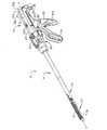
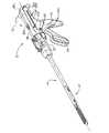
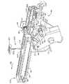
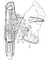
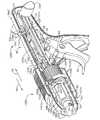
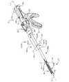
まず、図面を参照されたい。各図面において、同様の参照符号は、同様の構成要素を示している。図1は、本発明の様々な実施形態の固有の利点を実施できる、例示する形態では具体的に外科ステープル留め器具10である、再使用可能な外科器具を示している。外科ステープル留め器具10は、ハンドル組立体12および細長い本体14を含むことができる。図1は、関節動作可能な使い捨て装着ユニット16が結合された外科ステープル留め器具10を例示している。図2は、非関節動作使い捨て装着ユニット16’が結合された外科ステープル留め器具10を例示している。使い捨て装着ユニット16、16’は、内部に複数の外科ステープルを受容するカートリッジ組立体18を含む器具組立体17を含むことができる。器具組立体17は、ステープル成形アンビル20を含むこともできる。このような使い捨て装着ユニット16、16’は、組織の切断、および切断部の両側へのステープル留めなどの外科処置を行うことができる。本発明の様々な実施形態は、参照して開示内容の全てを本明細書に組み入れるミリマン(Milliman)らによる米国特許第5,865,361号に開示されている使い捨て装着ユニットと共に使用することができる。[Detailed explanation]
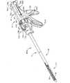
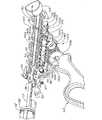
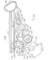
Reference is first made to the drawings. Like reference symbols in the various drawings indicate like elements. FIG. 1 illustrates a reusable surgical instrument, which in the illustrated form is specifically a
本明細書で用いる語「遠位」および「近位」は、器具のハンドル組立体を把持している臨床医を基準にしていることを理解されたい。したがって、器具組立体17は、より近位のハンドル組立体12に対して遠位側である。さらに、便利さと見やすさのために、「垂直」、「水平」、「上方」、「下方」、「右」、および「左」などの空間の位置関係を表す語は、本明細書では、図面に対して用いていることが認識されるであろう。しかし、外科器具は、様々な向きおよび位置で用いられ、これらの語は、限定するものでも絶対でもない。 It should be understood that the terms “distal” and “proximal” as used herein refer to the clinician holding the instrument handle assembly. Thus, the
上記したように、米国特許第5,865,361号に開示されているような従来の外科ステープル留め器具は、分解が容易でないため、器具を再使用できるようにするための再処理(すなわち、再滅菌)に適していない。図1〜図20に示す外科ステープル留め器具10は、手軽に再処理できるように構成されており、詳細を後述する関節動作可能な使い捨て装着ユニット16(図1)および非関節動作使い捨て装着ユニット16’(図2)と共に使用することができる。外科ステープル留め器具10の様々な実施形態は、内部に受容された様々な構成要素の清掃および滅菌を容易にするように構成されたハンドル組立体12を用いることができる。例えば、ハンドル組立体12は、固定ハンドル部分22、可動ハンドル24、およびバレル部分26を含むことができる。ステープル留め器具10の長さ方向軸「L‐L」を中心にハンドル組立体12に対する細長い本体14の回転を容易にするために、回転可能なノブ28を、バレル部分26の前端部に取り付けることができる。詳細は後述するが、一部のハンドル組立体の実施形態は、回転可能なノブ28に近接したバレル部分26の前端部に取り付けられる関節動作レバー30を含むこともできる。他の実施形態は、非関節動作使い捨て装着ユニットと共に使用するように設計することができるため、ハンドル組立体12は、このような関節要素を含まなくても良い。ハンドル組立体12は、互いに結合されるとハンドルハウジング36を形成する第1のハウジングセグメント36aと第2のハウジングセグメント36bとから形成することができるハンドルハウジング36をさらに含むことができる。ハンドル組立体12の容易な分解を促進するために、ハウジングセグメント36a、36bを、少なくとも1つ、好ましくは3つの迅速取外しファスナー400で互いに結合することができる。 As noted above, conventional surgical stapling instruments such as those disclosed in U.S. Pat. No. 5,865,361 are not easy to disassemble and are therefore reprocessed to allow the instrument to be reused (i.e., Not suitable for re-sterilization. The
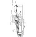
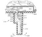
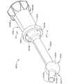
図3に示すように、迅速取外しファスナー400は、ハウジングセグメント36aに形成された対応する離隔部材410の孔412に受容される大きさである、バレルすなわち本体部分404が延出したネジ頭部402を含む差込み型ファスナーを含むことができる。ロッドすなわち交差部材406が、孔412の両側のスロットセグメント414内に受容される大きさの実質的にT型のコネクタ部分408を形成するために本体部分404内に取り付けられている。スロットセグメント414は、T型コネクタ部分408が孔412およびスロットセグメント414内に挿入されて、図3の矢印「T」で例示されている方向に回転されると、ロッド406が、コネクタ部分408を所定の位置に取外し可能に保持するように構成されている。様々な実施形態では、迅速取外しファスナー400の本体部分404をハウジングセグメント36bの対応する孔に挿入し、次いで、迅速取外しファスナー400を第2のハウジングセグメント36bに取外しできないように結合するために、ロッドすなわち交差部材406を本体部分404に取り付けて、清掃/滅菌のためにハウジングセグメント36bを第1のハウジングセグメント36aから取り外した時に、迅速取外しファスナー400が、紛失せず、第2のハウジングセグメント36bに保持されるようにする。 As shown in FIG. 3, the quick-
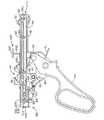
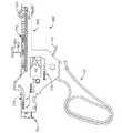
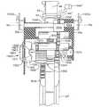
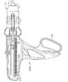
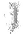
図4〜図8を参照されたい。可動ハンドル24を、清掃/滅菌のためにハンドルハウジング36から取り外すことができる発射組立体500に旋回可能に結合することができる。様々な実施形態では、発射組立体500は、可動ハンドル24を機能的に支持する内部フレーム組立体510を含むことができる。これらの図面から分かるように、可動ハンドル24を、ピボットピン38によって内部フレーム組立体510に旋回可能に取り付けることができる。捩りばねを含むことができる付勢部材40が、可動ハンドル24を固定ハンドル部分22から離れる方向に付勢する。図6〜図8を参照されたい。作動シャフト46を、内部フレーム組立体510内に支持することができ、この作動シャフト46は、歯付きラック48を含むことができる。ラック係合歯43を備えた駆動爪42が、ピボットピン44を中心に旋回可能に可動ハンドル24の一端に取り付けられている。図8を参照されたい。捩りばねを含むことができる付勢部材50が、駆動爪42を作動シャフト46の歯付きラック48に向かって付勢するように配置されている。図7を参照されたい。可動ハンドル24は、駆動爪42のラック係合歯43が作動シャフト46の歯付きラック48に接触して作動シャフト46を遠位方向「D‐D」に線形に前進させるために旋回可能である。作動シャフト46の遠位端部は、作動シャフト46の線形の前進に応じて制御ロッド52(図4)が線形に前進するように、制御ロッド52の近位端部49を受容するために、内部に形成されるキャビティ47を備えることができる。 Please refer to FIGS. The
内部フレーム組立体510は、ロック突出部55を備えたロック爪54をさらに含むことができる。ロック爪54は、ピボットピン57を中心に旋回可能に内部フレーム組立体510に結合されており、捩りばねを含むことができる付勢部材56によって作動シャフト46のキャビティ512内に付勢されている。ロック爪54のロック突出部55は、詳細を後述するように、使い捨て装着ユニットが細長い本体14に結合されていない時に、キャビティ512に係合して作動シャフト46を長さ方向の固定位置に保持するために移動可能である。 The
内部フレーム組立体510は、結合ロッド60によって作動シャフト46の近位端部に結合された右側引き戻しノブ32aおよび左側引き戻しノブ32bを含むことができる引き戻し機構58を機能的に収容することもできる。図6を参照されたい。結合ロッド60は、引き戻しノブ32aおよび32bをそれぞれ受容するための右側係合部分62aおよび左側係合部分62b、ならびに内部フレーム組立体510の一対の長さ方向スロット514内および作動シャフト46の近位端部近傍に形成されたスロット34a内を移動するように寸法決めされ構成された中心部分62cを含むことができる。引き戻しノブ32a、32bはそれぞれ、対応する係合部分62a、62bに対して押圧できるように内部にキャビティを有することができる。本発明の様々な実施形態では、結合ロッド60は、分解するために引き戻しノブ32a、32bが結合ロッド60から取り外された時に、結合ロッド60が内部フレーム組立体510に所定の位置で取り付けられた状態に維持されるように構成することができる。図7、図8、および図17を参照されたい。図6に示すように、中心部分62cは、作動シャフト46のキャビティ522内にスライド可能に受容されるリテーナ520の近位端部に形成された保持タブ(不図示)によって保持されて係合されるように構成されたノッチ63を備えることができる。引き戻しばね524が、リテーナ520を遠位側に引いて、リテーナ520の近位端部に形成された保持タブが結合ロッド60のノッチ63に保持されて係合するように、作動シャフト46の交差ポスト526とリテーナ520との間に取り付けられている。当業者であれば、引き戻しノブ32a、32bが結合ロッド60から取り外されても、結合ロッド60が、リテーナ520のタブによって内部フレーム組立体510に結合した状態で維持されることを理解できよう。 The
解除プレート64を、作動シャフト46に機能的に結合することができる。解除プレート64は、引き戻しノブ32a、32bの操作に応じて、作動シャフト46に対して移動するように取り付けられる。一対の離隔したピン66を、解除プレート64に形成された対応する一対の傾斜カムスロット68に係合するように作動シャフト46の側面から外側に延出させることができる。引き戻しノブ32a、32bが近位方向「PD」に移動すると、ピン66が、作動シャフト46および歯付きラック48に対して解除プレート64を下方に解放することができるため、解除プレート64の底部が歯付きラック48の下側に延びて、駆動爪42のラック係合歯43が歯付きラック48から係合解除される。横スロット70が、結合ロッド60の中心部分62cを受容するように解除プレート64の近位端部に形成されており、引き戻しノブ32a、32bを近位方向「PD」に引いて、作動シャフト46を引き戻し、従って制御ロッド52を近位方向「PD」に引き戻す際に、結合ロッド60の長さ方向の移動を可能にするために、細長いスロット34(図1)が、ハンドル組立体12のバレル部分26に画定されている。 A
様々な実施形態では、内部フレーム組立体510は、プランジャー82および旋回可能なロック部材83を含むことができる発射ロックアウト組立体80を機能的に支持することもできる。図7および図8を参照されたい。プランジャー82は、付勢ばね84によって中心位置に付勢されており、環状テーパカム面85を備えている。プランジャー82の各端部は、固定ハンドル部分22の上端部近傍のハンドルハウジング36を通って延びている。旋回可能なロック部材83は、ピボットピン86を中心に旋回可能にその遠位端部を取り付けることができ、ロックゲート88、およびスロット89が内部に形成された近位延長部90を含むことができる。図7および図8を参照されたい。旋回可能なロック部材83をばね93(図9)によって付勢して、ロック部材83に取り付けられたロックゲート88を作動シャフト46の底部のロック移動止め53内に進入させて、作動シャフト46の前進、従ってステープル留め器具10の発射を防止することができる。プランジャー82の環状テーパカム面85は、近位延長部90のテーパスロット89内に延びるように配置されている。ばね84の付勢に対するいずれか横方向へのプランジャー82の移動により、テーパカム面85が、近位延長部90のテーパスロット89の側壁に係合して、旋回可能なロック部材83がピボットピン86を中心に旋回し、ロックゲート88がロック移動止め53から外れて、作動シャフト46の前進が可能となる。 In various embodiments, the
図6〜図9から分かるように、センサリンク182を、内部フレーム組立体510によって機能的に支持することができる。これらの図面から分かるように、センサリンク182は、内部フレーム組立体510に対して長さ方向にスライドできるように、このセンサリンク182のスロット532を通るピンまたはねじ530によって内部フレーム組立体510にスライド可能に取り付けることができる。ばね531の遠位端部をねじ530に取り付け、ばね531の近位端部をセンサリンク182のフック533に掛けることができる。図6を参照されたい。ばね531は、センサリンク182を遠位方向「DD」に付勢する役割を果たす。センサリンク182は、ロック爪54と相互作用するように構成された内側に突出した近位端部537を有する近位ロックアーム535をさらに含むことができる。具体的には、装着ユニット16、16’がステープル留め器具10に取り付けられていない時は、センサリンク182は、ばね531によって遠位側に付勢されている。この「非装着」位置にある場合、近位ロックアーム535の近位端部537が、ロック爪54に係合しておらず、ロック爪54は、ロック突出部55がキャビティ512内に受容されて作動シャフト46を長さ方向の固定位置に保持するロック位置に保持されている。したがって、使い捨て装着ユニット16、16’が外科ステープル留め器具10に結合されていない場合は、ステープル留め器具10は、通常は発射することができない。 As can be seen in FIGS. 6-9, the
センサリンク182は、センサシリンダ178に形成されたフランジ179に接触する下方に延びた遠位タブ534をさらに備えることができる。図4および図5を参照されたい。詳細は後述するが、センサチューブ176が、センサシリンダ178と相互作用するように配置されている。図10を参照されたい。センサリンク182は、旋回可能なロック部材83のカム面83aに係合する下方に延びた端部538を備えたばねアーム536をさらに有することができる。図7を参照されたい。使い捨て装着ユニット16、16’が細長い本体14の遠位端部に結合されている時は、使い捨て装着ユニット16、16’がセンサチューブ176の遠位端部に係合してセンサチューブ176を近位側に駆動しているため、センサシリンダ178およびセンサリンク182が近位側に駆動されている。センサリンク182が近位側に移動すると、ばねアーム536の端部538がカム面83aの近位側に移動し、ばね93の付勢によって、ロック部材83が、ステープル留め器具10の発射許容位置(すなわち、作動シャフト46の作動を許容する位置)から、ロックゲート88が作動シャフト46のロック移動止め53内に受容された阻止位置に移動し、ステープル留め器具10の発射が防止される。センサリンク182は、使い捨て装着ユニット16がない場合、発射を防止する。ロック部材83は、アンビル組立体20が開閉している時に発射を防止する。また、センサリンク182が近位側に移動すると、近位ロックアーム535の近位端部537により、ロック爪54が旋回して、ロック突出部55がキャビティ512から外れて、作動シャフト46が作動することができるようになる。図8を参照されたい。 The
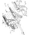
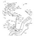
図4に示すように、ハンドルハウジング36は、ねじ29によって互いに結合できる成型半体部分28aおよび28bから形成するのが好ましい回転ノブ28の近位端部に形成された環状リブ118を受容するように構成された環状溝117を含むことができる。環状溝117およびリブ118は、回転ノブ28とハンドルハウジング36との間の相対的な回転を可能にする。図4に例示するように、細長い本体14は、センサチューブ176(図10を参照)および関節動作リンク123を支持する大きさである外側ケーシング124を含むことができる。構成要素123、124、176、および52からなるこのような組立体は、本明細書では時として「制御ロッド組立体125’’」と呼び、制御ロッド52に軸支持された他の構成要素も含むことができる。ケーシング124の近位端部は、回転ノブ28の遠位端部に形成された径方向突出部132を受容する寸法である、円周方向正反対に位置する開口128を含む。図4および図5を参照されたい。突出部132および開口128は、回転ノブ28と細長い本体14を、長さ方向かつ回転可能に互いに固定する。ハンドル組立体12に対する回転ノブ28の回転により、細長い本体14が、ハンドル組立体12に対して長さ方向軸L‐Lを中心に回転する。また、使い捨て装着ユニット16、16’は、細長い本体14の遠位端部に結合されるため、細長い本体14の回転によって使い捨て装着ユニット16、16’も回転することを理解されたい。 As shown in FIG. 4, the
様々な実施形態では、関節動作機構120は、回転ノブ28上に支持することができ、関節動作レバー30およびカム部材136を含む。図11を参照されたい。関節動作レバー30は、回転ノブ28にねじ込むことができるピボットピン140を中心に旋回可能に取り付けることができる。移動ピン142が、関節動作レバー30の底部のソケット131内に受容され、カム部材136に係合するためにこの底部から下方に延びることができる。カム部材136は、一側を貫通する細長いスロット146を備えたハウジング144を含むことができる。一対のカムプレート136a、136bを、一対のリベット145または他の適当なファスナーによってハウジング144に結合して、カムプレート組立体137を形成することができる。他の実施形態では、カムプレート組立体137は、ハウジング144と一体形成することができる。カムプレート136aおよび136bは、段付きカム面148を形成する段付きカム面148a、148bを有することができる。カム面148の各段は、ステープル留め器具10の関節動作の特定の段階に一致する。細長いスロット146は、関節動作レバー30から突出した移動ピン142を受容するように構成されている。カムプレート組立体137は、遠位段部150および近位段部152を形成するようにハウジング144に取り付けられる。近位段部152は、凹部154を含む。 In various embodiments,
図4から分かるように、関節動作機構120は、センサシリンダ178に形成されたタブ544を受容する大きさであるノッチ542が形成された直立アーム部分540を有する移動部材138をさらに含むことができる。移動部材138の遠位端部は、関節動作リンク123の近位端部から延びたフィンガー164を受容するように構成された開口548を備えたアーム546を含むことができる。図4および図10を参照されたい。例えば、テフロン(登録商標)などの非摩耗材料から形成できるピン166を、段付きカム面148内に受容される大きさにし、移動部材138に固定する。組立てた状態では、カム部材136の遠位段部150および近位段部152が、回転ノブ28に形成されたフランジ170および172の下側に位置するため、カム部材136が、ステープル留め器具10の長さ方向軸「L‐L」に対して横方向に移動するのが制限される。関節動作レバー30が、ピボットピン140を中心に旋回すると、カム部材136が回転ノブ28上を横に移動し、段付きカム面148がピン166に対して横に移動し、ピン166が段付きカム面148に沿って近位側または遠位側に移動する。ピン166が移動部材138に固定されているため、移動部材138が近位側または遠位側に移動し、関節動作リンク123が、対応して近位側または遠位側に移動する。 As can be seen from FIG. 4, the
センサシリンダ178は、カムプレート組立体137の凹部154内に受容されるように構成された凸部544を有することができる。関節動作使い捨てユニット16が、ステープル留め器具10の細長い本体14の遠位端部に機能的に結合されると、凸部544が、カム部材136の凹部154の近位側に移動する。凸部544が凹部154の近位側に位置した状態では、カム部材136が横方向に自由に移動して、ステープル留め器具10を関節動作させることができる。米国特許第5,865,361号に説明されているように、非関節動作使い捨て装着ユニット16’は、延長挿入先端部を備えていない。したがって、非関節動作使い捨て装着ユニット16’が細長い本体14内に挿入されても、センサシリンダ178が、凸部544を凹部154から移動させるのに十分な距離近位側に移動しない。したがって、カム部材136が、凹部154内に配置された凸部544によって横方向に移動するのが防止され、関節動作レバー30が、その中心位置に固定されている。 The
図4〜図9から分かるように、この実施形態は、オーバーライドワイヤ602が取り付けられたオーバーライドボタン601を有する発射ロックアウトオーバーライド組立体600を含むこともできる。オーバーライドワイヤ602は、内部フレーム組立体510の上面604に形成されたワイヤ型保持タブ606内にスライド可能に支持することができる。オーバーライドワイヤ602の遠位端部610は、センサリンク182の遠位端部の孔539内に取り付けられている。オーバーライドボタン601が近位方向「PD」に移動すると、オーバーライドワイヤ602がセンサリンク182を近位側に引き、これによりロック爪54が作動シャフト46とのロック係合を解除するように付勢されると共に、ばねアーム536の端部538がカム面83aの近位側に移動されて、ロック部材83が、ばね92の付勢によって、ステープル留め器具10の発射許容位置(すなわち、作動シャフト46の作動を許容する位置)から阻止位置、すなわちロックゲート88が作動シャフト46のロック移動止め53内に受容されて、プランジャー82が押圧されない限り、ステープル留め器具10の発射を防止する位置に旋回する。 As can be seen from FIGS. 4-9, this embodiment may also include a firing
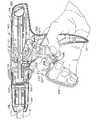
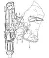
図1、図2、図9、および図10を参照されたい。ステープル留め外科器具10を使用する際には、初めに、使い捨て装着ユニット16、16’を細長い本体14の遠位端部に固定する。ステープル留め器具10は、例えば、約30〜約60mmのステープルの複数の線形の列をそれぞれ有する関節動作使い捨て装着ユニット16および非関節動作使い捨て装着ユニット16’と共に用いることができる。使い捨て装着ユニット16、16’を細長い本体14に結合する方法は、米国特許第5,865,361号に開示されている。使い捨て装着ユニット16、16’の挿入先端部が、センサチューブ176の遠位端部に係合されると、使い捨て装着ユニット検出機構が作動する。挿入先端部がセンサチューブ176に係合し、このセンサチューブ176を近位側に移動させると、センサチューブ176が、センサシリンダ178およびセンサリンク182を近位方向「PD」に移動させ、これによりロック部材83が非阻止位置から、ロックゲート88が作動シャフト46の運動を阻止する位置に反時計回りの方向に移動する。 Please refer to FIG. 1, FIG. 2, FIG. 9, and FIG. In using the stapling
使い捨て装着ユニット16、16’がステープル留め器具10に結合されると、器具組立体17を標的組織の周りに配置することができる。ステープル成形アンビル20とカートリッジ組立体18との間に標的組織をクランプする際には、可動ハンドル24を、捩りばね40の付勢に抗して固定ハンドル部分22に向かって旋回させ、駆動爪42を移動させて作動シャフト46の肩322に係合させる。肩322と駆動爪42との間の係合により、作動シャフト46が遠位側に前進し、従って制御ロッド52が遠位側に前進する。制御ロッド52は、内部の駆動梁を含め、その遠位端部が、使い捨て装着ユニット16、16’の軸駆動組立体に接続されているため、制御ロッド52の遠位側への移動により、駆動梁が遠位方向に移動し、これによりステープル成形アンビル20が、米国特許第5,865,361号に開示されている要領で旋回して閉じる。様々な実施形態では、可動ハンドル24の完全な1回のストロークにより、第1のストローク中で組織をクランプするには十分であるがステープルを発射させない約15mmの距離、作動シャフト46を前進させることができる。作動シャフト46は、この底部の移動止め53内に付勢されているロックゲート88によって可動ハンドル24が解放された後も、その長さ方向の位置に保持される。可動ハンドル24が解放されると、捩りばね40が可動ハンドル24を固定ハンドル22から離隔した位置に戻すため、駆動爪42がラック48の上を移動する。この位置では、駆動爪42が、歯付きラック48に作用して係合し、作動シャフト46がその長さ方向の固定位置にさらに保持される。 Once the
カートリッジ組立体18内に支持されたステープルを「発射」させる(すなわち、ステープルをステープル成形アンビル20内に駆動する)際には、可動ハンドル24を再び作動させる。様々な実施形態では、ステープル留め器具10は、約30〜約60mmのステープルの線形の列を有する使い捨て装着ユニット16、16’を受容することができる。このような構成では、ステープル留め器具10は、可動ハンドル24の各ストロークで作動シャフト46が15mm前進するように構成することができる。組織をクランプするために1回のストロークが必要であるため、可動ハンドル24は、ステープルを発射させるためには(n+1)回のストローク、作動させなければならない。このnは、ステープル留め器具10に取り付けられた使い捨て装着ユニットステープルの線形の列の長さを15mmで除した数値である。 To “fire” the staples supported in the cartridge assembly 18 (ie, drive the staples into the staple forming anvil 20), the
ステープルを発射する前に、発射ロックアウト組立体80を作動させて、ロックゲート88を阻止位置から非阻止位置に移動させなければならない。これは、プランジャー82を作動させてカム面85をロック部材83のスロット89の側壁に係合させ、これによりロック部材83を図8の反時計回りの方向に旋回させて行うことができる。この後、可動ハンドル24を、適切なストローク回数作動させて、作動シャフト46を前進させ、これにより制御ロッド52および駆動梁を遠位方向「DD」に前進させて、使い捨て装着ユニット16、16’を既知の要領で発射させる。ステープルの発射後、作動シャフト46、従って制御ロッド52および使い捨て装着ユニット16、16’の駆動部材を引き戻すために、引き戻しノブ32a、32bを近位側に引いて、ピン66により解除プレート64を歯49に対して図7の矢印「J」の方向に移動させて、駆動爪42の歯付きラック48の歯49との係合を解除することができる。 Prior to firing the staples, the
当業者であれば、使い捨て装着ユニット16、16’は、使用前に滅菌して滅菌パッケージング材料内にパッケージングすることを理解できよう。同様に、ステープル留め器具10も使用前に滅菌する。使い捨て装着ユニット16、16’は、使用後に廃棄する。ステープル留め器具10は、再使用のために再度滅菌することが考慮されているが、米国特許第5,865,361号に開示されているような従来の器具、ならびに使い捨て装着ユニットに使用するのに適した他の既知の器具は、それらの様々な内部の構成要素の滅菌を円滑にするための容易な分解に適していない。したがって、このようなユニットは、1回使用した後に廃棄される場合が多い。以下に詳しく説明するが、ステープル留め器具10は、再処理(すなわち、再滅菌)できるように容易な分解を促進するように構成されている。 One skilled in the art will appreciate that the
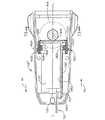
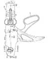
図12は、既に使用され、使い捨て装着ユニット(不図示)が除去された(図14のステップ700)後のステープル留め器具10を示している。点描620、622は、細長い本体14およびハンドル組立体12のそれぞれの例示的な汚染領域を示している。ステープル留め器具10の再処理を開始する際には、使用者が、発射オーバーライドボタン601を近位側に移動させて、このオーバーライドボタン601をその近位側の位置に保持する(ステップ702)。このような動作により、センサリンク182が上記の要領で近位側に移動し、使用者が、作動シャフト46を作動させることができる。使用者はまた、プランジャー82を移動させて、可動ハンドル24をサイクル動作させて作動シャフト46を作動させることができる。次いで、使用者は、可動ハンドル24を繰返しサイクル動作させて(図13に矢印「R」で示している)、制御ロッド52の汚染された部分624がケーシング124から延出するように制御ロッド52を延出させることができる(ステップ704)。図13を参照されたい。次いで、使用者は、制御ロッド52の露出した汚染部分624およびケーシング124の遠位端部を、例えば、エチレンオキシドや過酸化水素などの適切な洗浄または滅菌媒体630の中に入れる(ステップ706)。図15を参照されたい。 FIG. 12 shows the stapling
ハンドル組立体12を滅菌するために、ハンドル組立体12を容易に分解することができる(ステップ708)。図5を再び参照すると、使用者は、ねじまたはファスナー29を取り外して回転ノブセグメント28aと28bを分離することができる(ステップ710)。回転ノブセグメント28a、28b、および移動部材138を取り外して脇に置く(ステップ712)。次いで、左右の引き戻しノブ32a、32bを結合ロッド60から引き抜く(ステップ714)。次いで、3つの迅速取外しファスナー400を左ハウジング部分36bから取り外すことができ、これは、ファスナー400が左ハウジング部分36bに緩く結合されている場合を除く(ステップ716)。次いで、ハンドルハウジングセグメント36bを脇に置く(ステップ718)。次いで、使用者は、発射組立体500をハウジングセグメント36aから引き上げて、平坦な表面の上に置く(ステップ720)。次いで、使用者は、制御ロッド52の遠位端部を把持して、垂直に回転させる(図5の矢印「V」によって示している)(ステップ722)。次いで、制御ロッド52を、図4に示すように、作動シャフト46のキャビティ47から引き抜くことができる(ステップ724)。次いで、使用者は、センサシリンダ178をセンサチューブ176の近位端部から取り外すことができる(ステップ726)。このようにして、ステープル留め器具10を、図4に示すように各部品に分解することができる。次いで、使用者は、所望の清掃/滅菌サイクルを選択することができる(ステップ730)。図16を参照されたい。具体的には、使用者は、構成要素を適切な洗浄液630(図17)内に沈める「ウェット」清掃サイクルまたは放射線を用いる「ドライ」清掃サイクルを選択することができ、あるいは両方のサイクルの組合せを用いても良い。当業者であれば、図17は、洗浄媒体630の中に沈められているハンドル組立体の構成要素の一部のみを例示していることを理解できよう。ハンドル組立体の構成要素の全てを同時に沈めても良いし(容器が十分に大きい場合)、または全ての構成要素が洗浄されるまで1つずつか、もしくは小さなグループにして沈めても良いことを理解されたい(ステップ732)。しかし、摩耗または損傷した構成要素は、新しい滅菌された構成要素と交換して、ハンドル組立体を完成させることもできることを理解されたい。洗浄媒体630を含む容器632を揺り動かす、または従来の方法で洗浄媒体をかき混ぜるか他の方法で揺り動かして、洗浄媒体630を、内部フレーム組立体510の開口511から進入させて、内部に保持されている全ての構成要素に接触させるようにする(ステップ734)。全ての構成要素が、所望の時間、洗浄媒体630に曝されたら、これらの構成要素を洗浄媒体630から取り出して、空気乾燥させるか、または他の従来の方法で乾燥させることができる(ステップ736)。 To sterilize the
構成要素を洗浄媒体で洗浄したら(ステップ732〜736)、使用者は、構成要素を照射すること(ステップ740、742)を選択するか、または構成要素を照射しないこと(ステップ744)を選択し、この時点で、使用者は、詳細を後述するように特定の構成要素に潤滑剤を塗ることができる(ステップ746)。使用者が、構成要素をウェット洗浄した後またはウェット洗浄の代わりとして、分解した構成要素を照射することを選択した場合、使用者は、全ての構成要素の部品を適切なトレーまたは他の物(不図示)の上に置くことができる。次いで、放射線を、従来の放射線技術を用いて構成要素に照射することができる。例えば、電子ビーム照射を用いることができる。例えば、エチレンオキシド蒸気媒体や過酸化水素蒸気媒体などの他の形態の蒸気滅菌媒体を用いることもできる。 Once the component has been cleaned with the cleaning medium (steps 732-736), the user selects to irradiate the component (
構成要素を滅菌した後、特定の構成要素に潤滑剤を塗布することができる(ステップ746)。図18から分かるように、様々な構成要素では、潤滑剤の指示書き770が、内部フレーム組立体510に型押しまたは他の方法で設けることができる。例えば、ステアリン酸ナトリウムなどの滅菌潤滑媒体を、図18に示すように様々な構成要素に塗ることができる。 After the component is sterilized, a lubricant can be applied to the particular component (step 746). As can be seen from FIG. 18, in various components,
次いで、構成要素を、図19に概説するように再度組み立てることができる。構成要素の組立てを容易にするために、内部に一連の相補的なキャビティ792、794を有する滅菌組立部材すなわちトレー790を用いることができる。図20を参照されたい。再組立てのある方法では、回転ノブセグメント28aを組立トレー790の相補的な形状のキャビティ792内に入れることを含むステップ750を含む。引き戻しノブ32aを、相補的なキャビティ794内に入れることができる(ステップ752)。第1のハウジングセグメント36aを、相補的なキャビティ796内に入れることができる(ステップ754)。移動部材138を、右側回転部材28a内に配置し、移動部材138に取り付けられたピン166を、右側回転ノブセグメント28aのフランジ170、172の下側に取り付けられたカム部材136の段付きカムスロット148内に挿入する(ステップ756)。センサシリンダ178を、制御ロッド52の近位端部に配置することができる(ステップ758)。制御ロッド組立体125を、その遠位端部を上にして垂直に配置する。センサシリンダ178を、制御ロッド52に保持する(ステップ760)。制御ロッド52の近位端部を、作動シャフト46のキャビティ47内に挿入する(ステップ762)。次いで、制御ロッド組立体125を、左下方に回転させて、作動シャフト46に対する取り付けを完了する(ステップ764)。センサシリンダ178を、タブ544が下方にくるまで回転させる(ステップ766)。結合された発射組立体500および制御ロッド組立体125を、組立トレー790の対応するキャビティ798、792、および796内にある第1のハンドルハウジングセグメント36aおよび右側回転ノブセグメント28aの中に入れる。センサシリンダ178のロックアウトタブ544を、移動部材138のノッチ542の中に入れる(ステップ768)。結合ロッド60を、右側引き戻しノブ32aの孔(不図示)の中に入れるために整合させることができる(ステップ770)。次いで、第2のハンドルハウジングセグメント36bをこの組立体の上に載せて整合させ、迅速取外しファスナー400が、ハンドルハウジングセグメント36aと36bを互いに結合することができるようにする(ステップ772)。回転ノブセグメント28bを回転ノブセグメント28aに整合させて、ねじ29で結合することができる(ステップ774)。次いで、左側引き戻しノブ32bを引き戻しシャフト60に押し付けて、組立を完了することができる(ステップ776)。 The components can then be reassembled as outlined in FIG. To facilitate assembly of the components, a sterile assembly or
上記の米国特許第5,865,361号に開示されている発射ロックアウト組立体はもちろん、上記の発射ロックアウト組立体80も、可動ハンドル24のサイクル動作によって作動シャフト46を作動できるように臨床医がプランジャー82を押圧しなければならないため、使用が困難であろう。このような構成では、通常は、臨床医が、両手を使う必要がある(一方の手でハンドル組立体を保持して可動ハンドルを作動させ、他方の手でプランジャー82を押す)。器具を発射させるために臨床医が両手を使う必要のないより人間工学的に優れた発射ロックアウトトリガー構造を備えた外科ステープル留め器具を有することがより望ましいであろう。図21〜図33は、ステープル留め器具810が、器具を発射させるために両手を使用する必要がなく格段に使いやすい発射ロックアウトシステム880を用いている点を除き、上記のステープル留め器具10、米国特許第5,865,361号に開示されているステープル留め器具、またはプランジャー型ロックアウト組立体を用いる他の従来の外科器具に実質的に類似したステープル留め器具810を例示している。 The
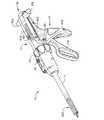
図21および図22を参照されたい。ハンドル組立体12は、そのバレル部分26および固定ハンドル部分22を形成する成形ハンドルハウジングセグメント36a、36bから形成するのが好ましいハンドルハウジング36を含む。可動ハンドル824は、ハンドルハウジングセグメント36aと36bとの間にピボットピン38を中心に旋回可能に支持することができる。図22を参照されたい。捩りばねを含むことができる付勢部材40は、可動ハンドル824を固定ハンドル22から離れる方向に付勢する。作動シャフト46は、ハンドルハウジング36のバレル部分26内に支持することができ、歯49のラック48を含む。ラック係合歯43を備えた駆動爪42は、可動ハンドル824の一端にピボットピン44を中心に旋回可能に取り付けることができる。捩りばねを含むことができる付勢部材50は、駆動爪42を作動シャフト46のラック48に向かって付勢するために用いることができる。可動ハンドル824が作動されると(例えば、旋回すると)、駆動爪42が移動して、ラック係合歯43が作動シャフト46の歯付きラック48に係合して、作動シャフト46を遠位方向「DD」に線形に前進させる。作動シャフト46の前端部は、作動シャフト46の線形の前進に対応して制御ロッド52が線形に前進するように制御ロッド52の近位端部53(図23)を受容するように内部に形成されたキャビティ47を備えている。 See FIGS. 21 and 22. The
ステープル留め器具810は、ラックロック部材55を有するロック爪54をさらに有することができる。ラックロック部材55は、ピボットピン57を中心に旋回するようにハンドルハウジング36内に取り付けることができ、好ましくは捩りばねである付勢部材56によって歯付きラック48に向かって付勢されている。ロック爪54のラックロック突出部55は、作動シャフト46のキャビティ512内に進入するように配置されているため、ラックロック突出部55がキャビティ512内に存在する場合、使い捨て装着ユニットがステープル留め器具810に結合されていないと、作動シャフト46が長さ方向の固定位置に保持される。 The
様々な実施形態は、結合ロッド60によって作動シャフト46の近位端部に結合された右側引き戻しノブ32aおよび左側引き戻しノブ32bを含むことができる引き戻し機構58を含むこともできる。図22を参照されたい。結合ロッド60は、引き戻しノブ32a、32b内に受容される右側および左側係合部分62aおよび62b、ならびに作動シャフト46の近位端部の近傍に形成された一対の長さ方向スロット34a内を移動するように寸法決めされ構成された中心部分62cを含むことができる。解除プレート64を、作動シャフト46に機能的に結合することができる。解除プレート64は、引き戻しノブ32a、32bの操作に応じて作動シャフト46に対して移動するように取り付けられる。一対の離隔したピン66が、作動シャフト46の側面から外側に延びて、解除プレート64に形成された一対の対応する傾斜カムスロット68に係合することができる。引き戻しノブ32a、32bが近位方向「PD」に移動すると、ピン66が、作動シャフト46および歯付きラック48に対して下方に解除プレート64を解放し、解除プレート64の底部が歯付きラック48の下側に延びて、駆動爪42の係合歯43が歯付きラック48から係合解除される。スロット70を、結合ロッド60の中心部分62cを受容するために解除プレート64の近位端部に形成することができる。引き戻しノブ32a、32bが近位方向「PD」に引かれて作動シャフト46が引き戻され、これにより引き戻し制御ロッド52が後方に引き戻される時に、結合ロッド60の長さ方向の移動を受容するために、細長いスロット34が、ハンドル組立体12のバレル部分26に設けられている。 Various embodiments may also include a
ステープル留め器具810は、センサリンク882がハンドルハウジング36に対して長さ方向にスライドできるように、センサリンク882のスロット532を通るピンまたはねじ530によってハンドルハウジングセグメント36aにスライド可能に取り付けできるセンサリンク882をさらに含むことができる。ばね531の遠位端部は、ねじ520に取り付けることができ、ばね531の近位端部は、センサリンク882のフック533に掛けることができる。図22を参照されたい。ばね531は、センサリンク882を遠位方向「DD」に付勢する役割を果たす。センサリンク882は、ロック爪54と相互作用するように構成された内側に突出する近位端部537を有する近位ロックアーム535をさらに含む。具体的には、使い捨て装着ユニット16、16’が器具810に取り付けられていないと、センサリンク882が、ばね531によって遠位側に付勢される。この「非装着」位置では、近位ロックアーム535の近位端部537が、ロック爪54に係合していないため、ロック爪54がロック位置に保持され、ロック突出部55がキャビティ512内に受容されて作動シャフト46が長さ方向の固定位置に保持されている。したがって、使い捨てユニット16、16’が器具810に結合されていないと、器具810を発射することができない。 The
図23を参照されたい。使い捨て装着ユニット検出機構を、ステープル留め器具810内において、細長い本体14からハンドル組立体12の中まで延在させることができる。この検出機構は、外側ケーシング124内にスライド可能に支持されたセンサチューブ176を含むことができる。センサチューブ176の遠位端部は、細長い本体14の遠位端部に向かって配置され、センサチューブ176の近位端部は、一対の凸部180’によってセンサシリンダ178’の遠位端部内に固定されている。センサリンク882の遠位端部は、センサシリンダ178’のフランジ状の近位端部190’に当接するように向きが合わせられている。 See FIG. A disposable loading unit detection mechanism can extend from the
センサリンク882は、センサシリンダ178’に形成されたフランジ179に接触するための下方に延びた遠位タブ534をさらに有することができる。図22および図23を参照されたい。詳細は後述するが、センサチューブ176は、センサシリンダ178’と相互作用するように向きが合わせられている。図23を参照されたい。使い捨て装着ユニット16、16’が、細長い本体14の遠位端部に結合されると、使い捨て装着ユニット16、16’がセンサチューブ176の遠位端部に係合してセンサチューブ176を近位側に移動させ、これによりセンサシリンダ178’およびセンサリンク882が近位側に移動される。センサリンク882が近位側に移動すると、近位ロックアーム535の近位端部537がロック爪54を旋回させて、ロック突出部55がキャビティ512から出て、作動シャフト46の作動が可能となる。 The
また、ステープル留め器具810は、以下に示す点は異なるが、上記に詳細に説明されたタイプおよび構造の関節動作機構120を用いることができる。様々な実施形態では、関節動作機構120は、回転ノブ28上に支持することができ、関節動作レバー30、カム部材136、および移動部材138’を含むことができる。様々な実施形態では、移動部材138’は、回転ノブ28の内壁に沿って形成された溝(不図示)内にスライド可能に受容されるように構成された複数のリッジ156を含むことができる。リッジ156とこれらの溝との間の係合は、回転ノブ28と移動部材138’の相対的な線形運動は可能にするが、回転ノブ28と移動部材138’の相対的な回転を防止する。移動部材138’の遠位端部は、関節動作リンク123の近位端部から延びたフィンガー164を受容するように構成された開口162を含むアーム160を含むことができる。図23を参照されたい。 Also, the stapling
組立てた状態では、カム部材136が、ステープル留め器具810の長さ方向軸「L‐L」に対して横に移動するのを制限するために、カム部材136の近位段付き部分150および遠位段付き部分152が、回転ノブ28に形成されたフランジ170および172の下側に位置している。関節動作レバー30がピボットピン140を中心に旋回すると、カム部材136が、回転ノブ28上を横方向に移動して、段付きカム面148(図11を参照)がピン166に対して横方向に移動し、ピン166が段付きカムスロット148に沿って近位側または遠位側に押される。ピン166は、移動部材138’に固定されているため、移動部材138’が近位側または遠位側に移動し、これに応じて第1の作動リンク123が近位側または遠位側に移動する。図23および図24を参照されたい。 In the assembled state, the
再び図24を参照されたい。カム部材136は、凹部154を含むことができる。凹部154内に受容されるように構成された凸部186を有するロックリング184は、制御タブ部分188’と近位フランジ部分190’との間でセンサシリンダ178’の周りに配置される。図23を参照されたい。フランジ部分190’とロックリング184との間に配置されるばね192’が、ロックリング184をセンサシリンダ178’に対して遠位側に付勢する。延長された先端部分を有する関節動作使い捨て装着ユニット16が、ステープル留め器具810の細長い本体14の遠位端部内に挿入されると、挿入先端部により、制御タブ部分188’が近位側に移動してロックリング184に係合し、ロックリング184および凸部186が、カム部材136の凹部154の近位側に押される。凸部186が凹部154の近位側に位置する状態では、カム部材136が、自由に横方向に移動して、ステープル留め器具810を作動させることができる。他の非関節動作使い捨て装着ユニットは、延長された挿入先端部を有していないことがある。この場合、非関節動作使い捨て装着ユニット16が細長い本体14に結合されても、センサシリンダ178’は、凸部186を凹部154から移動させるのに十分な距離近位側に引き戻されない。したがって、カム部材136は、凹部154内に位置するロックリング184の凸部186によって横方向に移動するのが防止され、関節動作レバー30は、その中心位置に固定されている。 Please refer to FIG. 24 again. The
図23を参照されたい。細長い本体14の遠位端部は、使い捨て装着ユニット16、16’を細長い本体14の遠位端部に結合する際に作動させることができる制御ロッドロック機構900を含むことができる。制御ロッドロック機構900は、ばね904によって遠位側に付勢されるブロックプレート902を含むことができ、傾斜カム面908を有する近位フィンガー906を含む。様々な実施形態では、ロックタブ912が延出した発射シャフトロック910を用いることができる。ロックタブ912は、制御ロッド52のノッチ914に選択的に係合するように構成することができる。発射シャフトロック910は、板ばね(不図示)などの形態の付勢部材を備えることができ、この発射シャフトロック910を通るロックピン916を有する。板ばねは、ブロックプレート902の近位端部が前方の遠位位置にある場合、発射シャフトロック910を外側に付勢する役割を果たす。ブロックプレート902は、ロックタブ912から離隔した遠位位置から、ロックタブ912の後側の近位位置に移動可能とすることができる。この近位位置では、ブロックプレート902が、ロックタブ912をセンサチューブ176のスロット918内に進入させて、制御ロッド52のノッチ914に係合させる。 See FIG. The distal end of the
詳細は後述するが、使い捨て装着ユニット16、16’を細長い本体14の遠位端部内に挿入する際、使い捨て装着ユニット16、16’が回転して細長い本体14に係合してブロックプレート902を近位位置に付勢するため、ブロックプレート902のカム面908が、使い捨て装着ユニット16、16’の凸部に係合する。組立ての際に、ノッチ914内に配置されたロックタブ912が、ブロックプレート902によってノッチ914内に保持されると共に、凸部が、カム面908に係合して制御ロッド52の長さ方向の移動を防止する。使い捨て装着ユニット16、16’が細長い本体14に対して適切に配置されると、使い捨て装着ユニット16、16’の近位端部の凸部がカム面908を通過して、ばね904がブロックプレート902をその遠位位置に戻すため、後の制御ロッド52の長さ方向の移動が可能となる。使い捨て装着ユニットの凸部がカム面908を通過すると、使い捨て装着ユニット16、16’が細長い本体14に適切に取り付けられたことを示す可聴クリック音を発することができることを理解されたい。 As will be described in detail below, when the disposable mounting
ここで、図22、図25、および図26を参照されたい。ステープル留め器具810は、改善された発射ロックアウト組立体880を用いることができる。この実施形態では、可動ハンドル824は、発射解放トリガー932の近位部分を受容する大きさのキャビティ930を備えることができる。これらの図面から分かるように、発射解放トリガー932は、表面に凸部934を備えることができ、解放ばね936が、キャビティ930の底部と凸部934との間に延在して、発射解放トリガー932を「A」方向に付勢することができる。図26に最も具体的に示すように、発射解放トリガー932は、この発射解放トリガーが「B」方向に押された時に、可動ハンドル824に形成されたスロット825内にスライド可能に延びる大きさの近位尾部940を有することができる。改善された発射ロックアウト組立体880は、歯車リンク組立体950をさらに含むことができる。様々な実施形態では、歯車リンク組立体950は、可動ハンドル824に取り付けられた第1の歯車ピン954上に回転可能に受容される第1の歯車952を含むことができる。第1の歯車952は、発射解放トリガー932の尾部940に形成された解放トリガー歯車ラック960に噛合するように構成された第1の歯車セグメント956を有することができる。第1の歯車952は、この第1の歯車952および解放爪970に旋回可能にピンまたは他の方法で取り付けられた第1の接続リンク972によって解放爪970に連結することができる。図22および図25から分かるように、解放爪970は、ピン38に旋回可能に支持することができる。 Refer now to FIGS. 22, 25, and 26. FIG. The
様々な実施形態では、解放爪970は、解放ピン980に係合するように構成された係合部分974を有することができる。解放ピン980は、第2の接続リンク982に取り付けられ、かつ可動ハンドル824に形成された弧状スロット826内に移動可能に拘束される。この〔詳細な説明〕を読み進めれば、スロット826が、可動ハンドル824の作動による第2の接続リンク982の移動を防止することが明らかになるであろう。第2の接続リンク982は、ハンドルハウジングセグメント36a、36bによって支持された歯車ピン992に回転可能に軸支持されたゲート歯車990に旋回可能にピンまたは他の方法で取り付けることができる。ゲート歯車990は、ロックゲート996に形成されたゲートラック998に噛合するように向きが合わせられた歯車の歯994のセグメントを有する。ロックゲート996は、ハンドルハウジングセグメント36aと36bとの間に延在するゲートピン1004に支持されるゲートばね1000の一部1002を受容するように構成されたスロット997を備えている。ゲートばね1000は、ロックゲート996を「C」方向に付勢する役割を果たす。図26を参照されたい。 In various embodiments, the
発射ロックアウト組立体880の動作を、図27〜図30を参照して説明する。図27は、使い捨て装着ユニット(不図示)内で組織をクランプする前のステープル留め器具810を例示している。この図から分かるように、解放爪970の係合部分974は、この動作の段階では、解放ピン980に接触していない。同様に図から分かるように、ロックゲート996の上端部が、作動シャフト46の遠位端部に位置している。図28は、使い捨て装着ユニットのステープル成形アンビルを上記の要領で閉じる可動ハンドル824の第1の作動を例示している。臨床医は、発射解放トリガー932をまだ押していないが、人指し指を発射解放トリガー932の作動部分933の後側に適切に置いている。可動ハンドル824を作動させて、作動シャフト46を、上記の要領で駆動爪42によって遠位方向「DD」に駆動する。図28から分かるように、作動シャフト46は、ロックゲート996の端部が作動シャフト46のロック移動止め53および解除プレート64の対応するロック移動止め53’内に進入している位置に移動する。図25により分かりやすく示すように、ロックゲート996の上端部は、ロックゲート996の垂直に延びた近位側面1005に交わる面取り部分またはテーパ部分999を備えている。同様に図25から分かるように、作動シャフト46のロック移動止め53は、傾斜面1006、1007および垂直レッジ部分1008を有する。ロックゲート996の上端部が、ゲートばね1000によってロック移動止め53内に完全に押されると、ロックゲート996の近位側面1005が、作動シャフト46の垂直レッジ1008に当接して、作動シャフト46の移動を防止している。しかし、ロックゲート996が方向「D」に引かれると、傾斜面1006、1007、およびロックゲート996上の面取り面999により、ロックゲート996が作動シャフト46から離隔するように完全に付勢しなくても、作動シャフト46がロックゲート996を越えて長さ方向に移動することができる。 The operation of firing
再び図28を参照されたい。この位置にある場合、可動ハンドル824のスロット826により、ピン980によって第2の接続リンク982を移動させてロックゲート996を作動させることなく、可動ハンドルを固定ハンドル部分22に向かって引くことができる。図28から分かるように、ばね1000は、ロックゲート996がロック移動止め53、53’内に受容され、かつその近位面998が作動シャフト46の垂直レッジ1008に当接するブロック位置にロックゲート996を付勢している。可動ハンドル824を図28に示す第1の位置に引いて、ステープル成形アンビルを閉じたら、臨床医は、ハンドル閉鎖ばね40の付勢力によって図29に例示する位置まで可動ハンドル824を移動させることができる。この段階で、臨床医が器具17を再操作したい場合、または、臨床医が、図30に例示するように人指し指を発射解放トリガー932の作動部分933に載せることによって発射サイクルを開始したい場合は、引き戻しノブ32a、32bを近位側に引いて、ステープル成形アンビルによる組織のクランプを解除することができる。 Please refer to FIG. 28 again. When in this position, the
図31では、臨床医は、発射解放トリガー932を押圧している。このような動作により、解放トリガー尾部940の解放トリガー歯車ラック960が、第1の歯車952の第1の歯車セグメント956に噛合して、第1の歯車952が反時計回りの方向「CCW」に回転する。第1の歯車952が反時計回りの方向に回転すると、この第1の歯車952が第1の接続リンク972を「E」方向に押すため、解放爪970が時計回りの方向「C」に回転する。解放爪970が時計回りの方向「C」に回転すると、係合面974が解放ピン980に接触して、第2の接続リンク982を「F」方向に引っ張る。第2の接続リンク982が「F」方向に移動すると、この第2の接続リンク982がゲート歯車990を反時計回りの方向「CCW」に回転させる。ゲート歯車990の歯車の歯994が、ゲートラック998に噛合して、ロックゲート996を「D」方向に移動させてロック移動止め53、53’との阻止係合を解除する。 In FIG. 31, the clinician has pressed the firing
図32は、可動ハンドル824の作動によって作動シャフト46が遠位方向「DD」に移動し始めた時の作動シャフト46に対するロックゲート996の位置を例示している。図面から分かるように、ロックゲート996の上側面取り部999が作動シャフト46の垂直縁1005に接触しており、作動シャフト46が遠位側に移動可能である。図33は、可動ハンドル824の第1の発射ストロークの完了を例示している。この図面から分かるように、作動シャフト46が遠位方向「DD」に前進する際は、ロックゲート996の上端部は、作動シャフト46の底部およびプレート64に接触している。リンク982の近位端部は、このストロークの際にスロット826の近位端部まで移動した。 FIG. 32 illustrates the position of the
図34は、後述する相違を除いて上記の発射ロックアウト組立体880と実質的に同じとすることができる代替の発射ロックアウト組立体880’を用いる代替のステープル留め外科器具810’を例示している。具体的には、発射ロックアウト組立体880’は、可動ハンドル824’に形成されたヘビ状通路828内に移動が限定された可撓性バー1020を用いている。可撓性バー1020は、第1の歯車952、第1の接続リンク972、および解放爪970の代わりである。可撓性バー1020の一端は、発射解放トリガー932に結合され、可撓性バー1020の他端は、同様にスロット828内に移動が限定された解放ピン980に接触するように拘束されている。したがって、発射解放トリガー932が押されると、可撓性バー1020が解放ピン980を押して第2の接続リンク982が「F」方向に移動する。第2の接続リンク982が「F」方向に移動すると、ゲート歯車990が反時計周りの方向「CC」に回転してロックゲート996が「D」方向に移動する。臨床医が発射解放トリガー932を放すと、解放ばね936により、発射解放トリガー932が「A」方向に移動し、これにより可撓性バー1020が解放ピン980から離れるため、解放ピン980がスロット828内を拘束されずに移動することができる。解放ピン980が拘束されなくなると、ゲートばね1000がロックゲート996を「C」方向に付勢することができる。ロックゲート996が「C」方向に付勢されると、ゲート歯車990が拘束されずに時計回りの方向「C」に駆動される。当業者であれば、上記の発射ロックアウト構造880、880’により、臨床医が片手で器具を操作できるようになることを理解できよう。これにより、米国特許第5,865,361号に開示されている発射ロックアウトシステム、および使い捨て装着ユニットに使用するように構成された他の従来のステープル留め器具に対して大幅に改善される。 FIG. 34 illustrates an alternative stapling
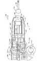
図35〜図46は、関節動作使い捨て装着ユニットに対応するように設計された従来の外科ステープル留め器具に関連した上記の問題の少なくとも一部に対処した外科ステープル留め器具1210を示している。より具体的には、図35に示すように、外科ステープル留め器具1210は、詳細を後述する選択的にロック可能な回転システム1220および関節動作システム1320(図36)を除き、上記の様々な器具と実質的に同じ構造にすることができる。上記の実施形態に用いた構成要素と同じ構成要素には、同じ参照符号を付し、当業者は、それらの構造および動作を説明する上記記載を参照することができる。 FIGS. 35-46 illustrate a
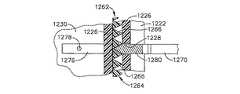
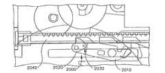
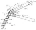
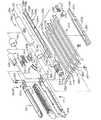
一実施形態では、外科ステープル留め器具1210は、細長い本体14が遠位側に突き出るように機能的に結合されたハンドル組立体12を含むことができる。細長い本体14の遠位端部は、関節動作使い捨て装着ユニット16に機能的に結合することができる。使い捨て装着ユニット16は、既知の要領で細長い本体14によって伝達される関節運動によって関節動作軸「A1‐A1」を中心に選択的に関節動作する器具組立体17を含むことができる。図35を参照されたい。本発明の様々な実施形態では、細長い本体14の近位端部は、ハンドルハウジング36’に結合された回転シュラウド1260に結合することができる。図36、図44、および図45から分かるように、ハンドルハウジング36’は、成型シュラウドセグメント1260aと1260bから形成するのが好ましい回転シュラウド1260の近位端部に形成された環状リブ1262を受容するように構成された環状溝117を含むことができる。環状溝117とリブ1262により、シュラウド1260とハンドルハウジング36’との間の相対的な回転が可能である。回転シュラウド1260の回転により、細長い本体14およびこの細長い本体14に取り付けられた使い捨て装着ユニットが、細長い本体14によって定められた長さ方向軸「L‐L」を中心に回転する。外科ステープル留め器具1210の様々な実施形態は、回転シュラウド1260を選択的にロックして長さ方向軸「L‐L」を中心としたハンドル組立体12に対する回転シュラウド1260の回転(ならびに細長い本体14および使い捨て装着ユニット16)を防止するために選択的にロック可能な回転システム1220を含むことができる。 In one embodiment, the
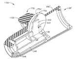
様々な実施形態では、ロック可能な回転システム1220は、ハンドルハウジング36’の遠位端部に形成されるかまたは他の方法で設けられる円筒遠位カバー1222を含むことができる。図36は、1つのカバーセグメント1222aが形成されたハンドルハウジング36’のハウジングセグメント36a’を例示している。当業者であれば、ハンドルハウジング36’のハウジングセグメント36b’に、カバーセグメント1222aと協働して遠位カバー1222を形成する合わせカバーセグメント1222bが形成されていることを理解できよう。図40を参照されたい。 In various embodiments, the
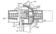
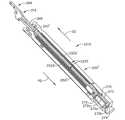
ロック可能な回転システム1220は、ブレーキシステム1229をさらに含むことができる。具体的には、カバーセグメント1222aは、内側スプライン部分1224aを有することができ、カバーセグメント1222bは、内側スプライン部分1224bを有することができる。内側スプライン部分1224a、1224bは協働して、ブレーキシステム1229のブレーキチューブ1230を支持するように構成された内側スプライン1224を形成する。様々な実施形態では、ブレーキチューブ1230には、遠位カバー1222の内側スプライン1224内に受容される大きさの外側スプライン1232が形成されているため、ブレーキチューブ1230は、遠位カバー1222に対して軸方向に移動することができるが、遠位カバー1222と共に回転するようになっている。ブレーキシステム1229は、回転シュラウド1260内に機能的に支持されるブレーキアームピン1250と相互作用するブレーキバンド1240をさらに含むことができる。ブレーキアームピン1250およびブレーキバンド1240の動作の詳細は後述する。
ブレーキチューブ1230は、セレクタースイッチ組立体1290に機能的に結合されたスイッチバー1270によって円筒遠位カバー1222に対して軸方向に移動することができる。図36から分かるように、スイッチバー1270は、近位端部1272および遠位端部1276を有する。近位端部1272は、セレクタースイッチ1292のシャフト部分1294を受容する孔1274を有する。シャフト部分1294は、スイッチバー1270の孔1274を通り、交差ピン1296によってスイッチバー1270に取り付けられる。加えて、セレクタースイッチ1292は、シャフト部分1294をハウジング36’に旋回可能に結合するファスナーピン1298を有することができる。セレクタースイッチ1292を所定の位置にロックするために移動止めばね1300を用いることができる。移動止めばね1300は、セレクタースイッチ1292がファスナーピン1298によって定められた軸「SA‐SA」を中心に遠位側および近位側に旋回する際に、交差ピン1296が係合するように構成された球状部分1302を有することができる。図36を参照されたい。したがって、セレクタースイッチ1292が近位側の位置(図42、図43、および図46)に旋回する際、およびセレクタースイッチ1292が遠位側の位置(図37、図38、図41、および図45)に旋回する際に、ばね1300の球状部分1302が、セレクタースイッチ1292およびスイッチバー1270を所定の位置に保持する。 The
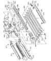
再び図36を参照されたい。スイッチバー1270の遠位端部1276は、スイッチバー1270をブレーキチューブ1230に結合するように構成された、遠位端部1276から突出する、コネクターピン1278を有することができる。図38を参照されたい。したがって、スイッチバーの近位方向「PD」および遠位方向「DD」への線形の移動により、ブレーキチューブ1230も、円筒遠位カバー部分1222内をこれらの方向に移動する。また、図36〜図39および図41〜図46から分かるように、スイッチバー1270の遠位端部1276は、この遠位端部1276に形成されるかまたは取り付けられるボルト1280をさらに有することができる。ボルト1280は、環状リブ1262に形成されるかまたは他の方法で設けられる一連の歯1266を含む回転ロックリング1264に選択的に噛合するように構成されている。図36から分かるように、円筒遠位カバー1222の環状溝117は、内側に延びたフランジ1226によって形成されている。フランジ1226は、スイッチバー1270の遠位端部1276を内部に通して受容する、このフランジ1226を貫通する溝1228を有する。したがって、詳細は後述するが、スイッチバー1270が遠位方向「DD」に移動すると、ボルト1280が、シュラウド1260の回転ロックリング1264の歯1266に噛合して、シュラウド1260がカバー1222およびシュラウド36に対して回転するのを防止することができる。図44を参照されたい。 Refer to FIG. 36 again. The
外科ステープル留め器具1210の様々な実施形態は、後述する固有かつ新規の関節動作システム1320をさらに含むことができる。関節動作システム1320は、細長い本体14を形成する構成要素に接触して、使い捨て装着ユニット16に伝達するために細長い本体14に関節運動を選択的に付与する。関節動作システム1320は、移動部材138’を含むことができる。例えば、移動部材138’は、シュラウド1260の内壁に沿って形成された溝1261内にスライド可能に受容されるように構成された複数のリッジ156を含むことができる。リッジ156とこれらの溝1261(図36および図37)との間の係合により、移動部材138’とシュラウド1260の相対的な回転が防止されるが、これらの構成要素間の相対的な線形運動は許容される。移動部材138’の遠位端部は、関節動作リンク123の近位端部から延びたフィンガー164を受容するように構成された開口162を含むアーム160を含むことができる。図37を参照されたい。また、この実施形態では、移動部材138’は、関節動作シュラウド1260の関節動作スロット1265を貫通する、移動部材138’から突出した、関節動作ピン166を有する。関節動作ピン166は、シュラウド1260上に受容される線形関節動作/回転グリップ1320に形成された孔1324(図36)に受容される。関節動作システムは、シュラウド1260の周りに互いに結合される2つのグリップセグメント1322a、1322bから形成できる線形関節動作/回転グリップ1322をさらに含むことができる。孔1324は、図36に示すようにグリップセグメント1322aに設けることができる。したがって、臨床医が、グリップ1322を近位方向「PD」および遠位方向「DD」に軸方向に移動させると、移動部材138’および関節動作リンク123もこれらの方向に移動して、関節動作可能な使い捨て装着ユニットが関節動作する。 Various embodiments of the
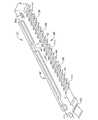
また、この実施形態では、ブレーキシステム1229は、関節動作システム1320の作動を防止するように構成することができる。例えば、図36を参照すると、ブレーキバンド1240は、ブレーキバンド溝1269を形成するべく、シュラウド1260の外面に形成された、離隔した肩フランジ1267間に受容されるように構成することができる。図36から分かるように、ブレーキバンド1240は、完全なリングを形成しておらず、ブレーキバンド1240の両端部1242は、互いに離隔して対向し、これらの間にカム受容開口1244を画定している。ブレーキバンド1240は、カム受容開口1244がブレーキカム1330を受容できる位置に来るようにブレーキバンド溝1269内に取り付ける。ブレーキカム1330には、シュラウド1260のブレーキカム孔1334に通すブレーキアームシフトピン1332が取り付けられている。図37から分かるように、ブレーキアームシフトピン1332は、ブレーキチューブ1230の遠位端部に形成されたシフト溝1234内に受容されるように構成されている。関節動作システム1320の一部を構成する線形関節動作/回転グリップ1322は、グリップ1320がシュラウド1260に対して軸方向に移動できるようにアンダーカット領域1326を有する。様々な実施形態では、グリップセグメント1322aは、グリップ1320がシュラウド1260上を軸方向に移動する際にインジケータピン1263が移動止め1328に係合する時に可聴クリック音もしくは可聴音を発するように、シュラウド1260から突出したインジケータピン1263(図41)に係合するように構成された一連の移動止め1328を備えることができる。図面には5つの移動止め1328を例示しているが、他の数の移動止め1328を用いても良い。 Also in this embodiment, the
外科ステープル留め器具1210の動作を、図37〜図39、図41、および図42〜図44を参照しながら説明する。図37〜図39は、外側ケーシング124を長さ方向軸「L‐L」を中心に選択的に回転できる「回転」モードにあるステープル留め器具1210を例示している。図37および図38から分かるように、セレクタースイッチ1292は、スイッチバー1270が近位方向「PD」に引かれた遠位位置に旋回している。スイッチバー1270が近位方向に引かれている場合は、回転ボルト1280が回転ロックリング1264(図39)から係合解除されているため、シュラウド1260が長さ方向軸「L‐L」を中心に回転することができる。上記したように、ケーシング124の近位端部は、シュラウド1260の遠位端部内に形成された径方向の突出部132を受容する寸法である円周方向正反対に位置する開口128を含む。図36および図38を参照されたい。突出部132と開口128は、シュラウド1260と細長い本体14を長さ方向かつ回転可能に互いに固定する。したがって、ハンドル組立体12に対するシュラウド1260の回転により、細長い本体14が、対応して、ハンドル組立体12に対して長さ方向軸L‐Lを中心に回転する。また、スイッチバー1270が、コネクターピン1278によってブレーキチューブ1230に結合されているため、スイッチバー1270が近位方向「PD」に移動すると、ブレーキチューブ1230も、円筒遠位カバー1222内を近位方向に移動する。上記したように、ブレーキカム1330のシフトピン1332は、ブレーキチューブ1230のシフト溝1234内に受容されている。ブレーキチューブ1230が近位側に移動すると、ブレーキアームピン1250に固定された径方向アームの遠位側の機能構造であるシフトピン1332によりブレーキカム1330が回転するため、ブレーキバンド1240の端部1242が径方向外側に押されて、シュラウド1260に対して線形関節動作/回転グリップ1322がロックされる。ブレーキバンド1240は、グリップ1322がシュラウド1260上を軸方向に移動するのを防止するが、グリップ1322の回転により、シュラウド1260が軸「L‐L」を中心に回転する。したがって、セレクタースイッチ1292が遠位方向に旋回すると、グリップ1320の回転により、細長い本体14およびこの細長い本体14に結合された使い捨て装着ユニットが、長さ方向軸「L‐L」を中心に回転することができる。 The operation of
臨床医が、使い捨て装着ユニットを関節動作させたい場合は、セレクタースイッチ1292を、図42、図43、および図46に例示するように近位方向「PD」に旋回させる。図42、図43、および図46から分かるように、セレクタースイッチ1292が近位方向に旋回すると、スイッチバー1270が遠位方向「D‐D」に軸方向に前進し、回転ボルト1280が回転ロックリング1264に係合してロックされる。ロックボルト1280が回転ロックリング1264に係合すると、シュラウド1260(および細長い本体14およびケーシング124)が、ハンドル組立体12に対して長さ方向軸「L‐L」を中心に回転することができない。スイッチバー1270が遠位方向に移動すると、スイッチバー1270がブレーキチューブ1230に取り付けられているため、ブレーキチューブ1230も遠位方向「D‐D」に移動する。ブレーキチューブ1230が近位側に移動すると、シフトピン1332が回転してブレーキカム1330が回転し、これによりブレーキバンド1240の端部1242が互いに向かって内側に移動することができるようになり、グリップ1320がシュラウド1260に対して移動することが可能となる。図46を参照されたい。様々な実施形態では、関節動作ピン166が、移動部材138’から延出してシュラウドセグメント1260aのスロット1265を通り、グリップセグメント1322aの孔1324内に受容されている。図36および図37を参照されたい。したがって、臨床医が、回転グリップ1322を近位方向「PD」および遠位方向「DD」に軸方向に移動させると、移動部材138’、およびアーム160によって移動部材138’に取り付けられた関節動作リンク123も移動する。したがって、臨床医が、回転グリップ1322を近位方向「PD」および遠位方向「DD」に軸方向に移動させると、移動部材138’および関節動作リンク123もこれらの方向に移動して、関節動作使い捨て装着ユニットが関節動作する。加えて、グリップ1322がシュラウド1260上を軸方向に移動すると、インジケータピン1263が移動止め1328に係合する時に可聴クリック音もしくは可聴音を発するため、臨床医が、関節動作の進行を音で確認することができる。 If the clinician wishes to articulate the disposable mounting unit, the
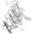
図46は、直立アーム部分540およびアーム546を有する移動部材138の使用を示している。アーム546は、関節動作リンク123(不図示)の近位端部から延びたフィンガー(不図示)を受容するように構成された開口548を含む。図4および図11を参照されたい。ピン166は、移動部材138に固定され、シュラウドのスロット1265を通り、シュラウド1322の孔1324内に延びる寸法である。この実施形態は、その他は、図37および図38に示す実施形態と同じように作用する。当業者であれば、上記の実施形態が、米国特許第5,865,361号に開示されているような使い捨て装着ユニットと共に使用するように構成された従来の器具に対して大幅に改善されていることを理解できよう。具体的には、上記の実施形態では、臨床医は、使い捨て装着ユニットを所望の位置に回転させてシュラウド1260を固定し、シュラウド1260のさらなる回転を防止することができる。次いで、臨床医は、シュラウド1260が所定の位置にロックされた状態で、使い捨て装着ユニットを関節運動させることができる。従来のユニットでは、臨床医が使い捨て装着ユニットを関節運動させようとする時に、回転ノブを自由に回転することができた。したがって、使い捨て装着ユニットが回転するのを防止するために、臨床医は、回転ノブに回転運動を与えないように注意しながら関節動作レバーを操作しなければならなかった。上記の実施形態は、この問題を解決している。 FIG. 46 illustrates the use of a moving
図47〜図51は、臨床医が使い捨て装着ユニット(不図示)を片手で関節動作させて発射させることができる使い捨て装着ユニットと共に使用するように構成された本発明の別の外科ステープル留め器具1410を例示している。具体的には、図47を参照すると、外科器具1410は、詳細を後述する関節動作システム1420を除き、上記の様々な器具の構成と実質的に同様である。上記の実施形態に用いた構成要素と同じ構成要素には、同じ参照符号を付しており、当業者であれば、それらの構成および動作を説明する上記記載を参照することができよう。 47-51 illustrate another
一実施形態では、外科ステープル留め器具1410は、ハンドル組立体12に機能的に結合することができ、かつこのハンドル組立体12から遠位側に突出する細長い本体14を有するハンドル組立体12を含むことができる。細長い本体14の遠位端部は、関節動作使い捨て装着ユニット16に結合することができる。使い捨て装着ユニットは、周知のように細長い本体14によって器具組立体17に伝達される関節運動によって関節運動軸「AA‐AA」を中心に選択的に関節動作可能な器具組立体17を含むことができる。 In one embodiment, the
ハンドル組立体12は、ハンドルハウジング36を含むことができ、可動ハンドル24を有する。可動ハンドル24は、ハンドルハウジング36に機能的に結合され、ハンドルハウジング36に対して動作ストロークによって移動可能である。上記の実施形態と同様に、可動ハンドル24を作動させて、細長い本体14の一部を含む制御ロッド52に機能的に結合された作動シャフト46に長さ方向の作動運動を加えることができる。図48〜図51から分かるように、作動システム1420は、関節動作トリガー1422を含むことができる。関節動作トリガー1422は、臨床医が、ハンドル組立体12を把持し、かつ可動ハンドル24を作動させることができる手の人指し指で関節動作トリガー1422を作動させることができるように、ハンドルハウジング36の固定部分22および可動ハンドル24に対して形状および向きを合わせることができる。トリガー1422には、垂直部分1426を有する駆動バー部分1424が取り付けられている。垂直部分1426は、関節動作トリガー1422が、ピボットピン1428を中心に「G」および「H」方向に選択的に旋回できるように、ピボットピン1428によってハンドルハウジング36に対して旋回可能に取り付けられている。図49を参照されたい。駆動バー部分1424は、関節動作バー1440に取り付けられた駆動ピン1434を受容するように構成されたスロット1432を有する駆動部分1430をさらに有することができる。図49から分かるように、関節動作バー1440は、ねじ1450、1452の一部を受容するように構成された一対の細長いスロット1442、1444を備えることができる。ねじ1450、1452は、細長いスロット1442、1444をそれぞれ通り、ハンドルハウジングセグメント36aに取り付けられているため、関節動作バー1440がハンドルハウジング36内を近位方向「PD」および遠位方向「DD」に長さ方向に移動するように制限される。関節動作バー1440の遠位端部は、関節動作ピン1446を有することができる。関節動作ピン1446は、他の点は詳細に上記した移動部材138’の構造および動作と同一にすることができる移動部材138’’の近位端部に設けられた環状溝139’’内に延びるように構成されている。すなわち、移動部材138’’は、回転ノブ28’’の内壁に沿って形成された溝内にスライド可能に受容されるように構成された複数のリッジ156を有することができる。リッジ156とそれらの溝との間の係合により、移動部材138’’と回転ノブ28’’との相対的な回転が防止されると共に、これらの構成要素間の相対的な線形運動が可能となる。移動部材138’’の遠位端部は、関節動作リンク123の近位端部から延びたフィンガー164を受容するように構成された開口162備えたアーム160を含むことができる。図48および図49を参照されたい。したがって、臨床医が関節動作トリガー1422を「G」方向に作動させると、駆動部分1430が関節動作バー1440を近位方向「PD」に引き、これにより移動部材138’’およびこの移動部材138’’に取り付けられた関節動作リンク123も近位方向「PD」に引かれ、関節動作リンク123に結合された使い捨て装着ユニットが、上記および後述の要領で右側方向に関節運動する。臨床医が、関節動作トリガー1422を「H」方向に引くと、駆動部分1430が関節動作レバー1440を遠位方向「DD」に押し、これにより移動部材138’’およびこの移動部材138’’に取り付けられた関節動作リンク123も遠位方向「DD」に引かれ、関節動作リンク123に結合された使い捨て装着ユニットが左側方向に関節運動する。 The
上記したように、この実施形態は、使い捨て装着ユニットが制御ロッド52に結合されているか否かを検出して、使い捨て装着ユニットが取り付けられていない場合は関節動作機構1420の作動を防止するために、上記したようにセンサチューブ176およびセンサリンク182に接触したセンサシリンダ178’を含むことができる。しかし、この実施形態では、センサチューブ178’のフランジ190’は、関節動作バー1440に形成された「非再装着」ロックアウトランプ1448と相互作用するように構成されている。図50および図51を参照されたい。使い捨て装着ユニットが細長い本体14および制御ロッド52に結合されていない場合は、センサチューブ178’が、図50に例示する位置に付勢されている。この図面から分かるように、関節動作バー1440の非再装着ロックアウトランプ1448が、センサチューブ178’のフランジ190’に係合しているため、関節動作バー1440が、「I」方向に横方向外側に付勢されている。また、この図面から分かるように、内側に延びたロック移動止め37が、ハンドルハウジングセグメント36aに形成されている。ロック移動止め37は、フランジ190’が非再装着ロックアウトランプ1448に係合して関節動作バー1440を「I」方向に付勢すると、関節動作バー1440のロックノッチ1445内に受容されるように構成されている。移動止め37がロックノッチ1445内に受容されると、関節動作バー1440を作動させることができない。したがって、使い捨て装着ユニットが器具1410に結合されていないと、関節動作トリガー1422を作動させることができない。使い捨て装着ユニットが細長い部材14、制御ロッド52、およびセンサバー176に結合されると、センサシリンダ178’が近位方向「PD」に付勢され、これによりフランジ190’が、図51に示されているように非再装着ロックアウトランプ1448から係合解除されて、関節動作バー1440の作動が可能となる。したがって、使い捨て装着ユニットがステープル留め器具1410に結合されると、関節動作トリガー1422を作動させることができる。 As described above, this embodiment detects whether or not the disposable mounting unit is coupled to the
当業者であれば、上記の関節動作機構1420により、臨床医がステープル留め器具を片手で操作できるようになることを理解できよう。これにより、米国特許第5,865,361号に開示されている関節動作機構、および使い捨て装着ユニットと共に使用するように構成された他の従来のステープル留め器具に対して大幅に改善される。 One skilled in the art will appreciate that the
図52〜図64は、臨床医が可動ハンドル24’’を操作して関節動作可能な使い捨て装着ユニット(不図示)を関節動作および発射できる関節動作可能な使い捨て装着ユニットと共に使用するように構成された本発明の別の外科ステープル留め器具1510を示している。一実施形態では、外科ステープル留め器具1510は、細長い本体14が遠位側に延出して機能的に結合されたハンドル組立体12を含むことができる。細長い本体14の遠位端部は、関節動作可能な使い捨て装着ユニット16に結合することができる。使い捨て装着ユニットは、周知のように細長い本体14により器具組立体17に伝達される関節運動によって関節動作軸「A1‐A1」を中心に選択的に関節動作する器具組立体17を含むことができる。詳細は後述するが、外科ステープル留め器具1510は、可動ハンドル24’’、作動シャフト46、および関節動作システム1520と相互作用する固有かつ新規のセレクター構造1512を用いることができる。セレクター構造1512が「発射」向きにある場合は、作動ストロークによる可動ハンドル部材24’’の操作により、作動シャフト46に発射運動が付与され、セレクター構造1512が「関節動作」向きにある場合は、作動ストロークによる可動ハンドル部材24’’の操作により、関節動作システム1520が作動する。上記の実施形態に用いた構成要素と同じ構成要素には、同じ参照符号を付しており、当業者であれば、それらの構成および動作を説明する上記記載を参照することができよう。 52-64 are configured for use by a clinician with an articulatable disposable mounting unit (not shown) that can be articulated and fired by manipulating the movable handle 24 ''. Figure 16 illustrates another
図52および図53から分かるように、セレクター構造1512は、アクセスできるようにハンドルハウジング36の外側に配置された関節動作セレクタースイッチ1522を含むことができる。関節動作セレクタースイッチ1522は、ハンドルハウジングセグメント36bを貫通する関節動作セレクタースイッチシャフト1524に結合することができ、関節動作システム1520の一部を構成するロッカーマウント1530に取り付けられている。第2の関節動作セレクタースイッチシャフト1526が、ロッカーマウント1530の他側から外側に突出し、セレクタースイッチ1522aに取り付けるためにハンドルハウジングセグメント36aを貫通しているため、ロッカーマウント1530が、シャフト1524、1526によって定められるロッカー軸「RA」を中心に旋回可能である。図60を参照されたい。図56〜図58から分かるように、関節動作システム1520は、それぞれがロッカーマウント1530内を自由に回転可能である第1の関節動作歯車1540および第2の関節動作歯車1550をさらに含む。第1および第2の関節動作歯車1540、1550は、他の点は上記の関節動作バー1440に類似した関節動作バー1440’の一部を構成する関節動作バー延長部1441’に選択的に係合するような向きに配置されている。図55から分かるように、関節動作バー延長部1441’は、ロッカーマウント1530の向きによって第1の関節動作歯車1540または第2の関節動作歯車1550により係合されるように構成された一連の孔1443’を備えている。 As can be seen in FIGS. 52 and 53, the
セレクター構造1512は、発射歯車1610と関節動作システムの一部を構成する関節動作伝達歯車列1600との間で相互作用するための固有かつ新規の歯車セレクタースイッチ組立体1560をさらに含むことができる。様々な実施形態では、関節動作伝達歯車列1600は、ハンドルハウジングセグメント36a、36bのソケット(不図示)内に回転可能に支持された第1の伝達歯車シャフト1604に取り付けられた第1の伝達歯車1602と、ハンドルハウジングセグメント36a、36bのソケット(不図示)内に回転可能に支持された第2の伝達歯車シャフト1608に取り付けられた第2の伝達歯車1606と、を含むことができる。様々な実施形態では、歯車セレクタースイッチ組立体1560は、ハンドルハウジングセグメント36bの対応する弧状スロット1564内に延びて駆動ディスク1566に取り付けられた一対のピン1563が突出した機能セレクタースイッチ1562を含むことができる。図61および図62を参照されたい。これらの図面から分かるように、駆動ディスク1566は、シフトディスク1570の対応するディスクの歯1571に選択的に噛合するように構成された一連の歯受容キャビティ1568を備えることができる。シフトディスク1570は、固定シャフト1574に回転しないように固定することができる。図61および図62から分かるように、固定シャフト1574の端部1575は、キャビティ1577内に受容されて、ロックピン1578によって取り付けられることができる。例えば、様々な実施形態では、端部1575は、固定シャフト1574がハンドルハウジングセグメント36aに対して回転しないようにハンドルハウジングセグメント36a内に成型することができる。図62から分かるように、シフトディスク1570は、このシフトディスク1570が固定シャフト1574上を軸方向に移動(回転しないで)できるように、固定シャフト1574の横スロット1576を通るシフトピン1580によって固定シャフト1574に回転しないように取り付けることができる。 The
図61および図62から分かるように、歯車セレクタースイッチ組立体1560は、駆動歯車部分1592および関節動作駆動歯車部分1594を含む駆動歯車組立体1590をさらに含むことができる。駆動歯車組立体1590は、固定シャフト1574上を軸方向に移動するように構成されており、固定シャフト1574に軸支持されたばね1596によって「J」方向に付勢されている。 As can be seen from FIGS. 61 and 62, the gear
関節動作システム1520の動作を、図57および図58を参照して説明する。関節動作を開始する際は、臨床医が、関節動作セレクタースイッチ1522a、1522bの一方を作動させる。一実施形態では、例えば、臨床医が、使い捨て装着ユニットを右側に関節動作させたい場合は、臨床医は、関節動作セレクタースイッチ1522a、1522bを下方(図52の矢印「L」)に旋回させる。セレクタースイッチ1522を下方に旋回させることにより、ロッカーマウント1530が、図58の反時計回りの方向「CCW」に旋回して、第2の関節動作歯車1550が、関節動作バー延長部1441’の孔1443’に噛合する。関節動作モードでは、歯車セレクタースイッチ組立体1560を、図59および図63に例示されている非作動位置に保持することができる。この位置にある場合、駆動歯車組立体1590は、可動ハンドル24に取り付けられるかまたは他の方法で成型されるハンドル歯車1620が、駆動歯車組立体1590の駆動歯車部分1592に噛合するように位置している。加えて、駆動歯車組立体1590の関節動作駆動歯車部分1594は、第1の伝達歯車1602に噛合している。図59から分かるように、駆動歯車組立体1590がこのように位置している場合、発射歯車シャフト1612に回転可能に支持された発射歯車1610が、駆動歯車組立体1590に係合していない。したがって、可動ハンドル24を作動させても、発射歯車1610は駆動されない。 The operation of the
セレクタースイッチ1522a、1522b、1562が上記のように位置している場合、臨床医は、可動ハンドル24を作動させて(ラチェットまたは旋回)ステープル留め器具1510に取り付けられた使い捨て装着ユニットを関節運動させることができる。可動ハンドル24が作動されると、ハンドル歯車1620が反時計回りの方向「CCW」に回転して、駆動歯車1592が時計回りの方向「CW」に回転し、これにより第1の伝達歯車1602が反時計回りの方向「CCW」に回転して、第2の伝達歯車1606が時計回りの方向「CW」に回転し、これにより第1の関節動作歯車1540が反時計回りの方向「CCW」に回転して、第2の関節動作歯車1550が時計回りの方向「CW」に回転し、これにより関節動作バー延長部1441’が近位方向「PD」に駆動される。図58を参照されたい。関節動作バー延長部1441’が近位方向「PD」に駆動されると、関節動作バー1440’が、移動部材138’’を駆動し、この移動部材138’’に取り付けられた関節動作リンク123が近位方向「PD」に引かれるため、関節動作リンク123に取り付けられた使い捨て装着ユニットが、上記および後述の要領で右側方向に関節運動する。使い捨て装着ユニットを左側に関節運動させる際は、臨床医が、関節動作セレクタースイッチ1522a、1522bを上方(図52の「M」方向)に旋回させる。セレクタースイッチ1522a、1522bが上方に旋回すると、関節動作ラック1530がラック軸「RA」を中心に時計回りの方向「CW」に旋回して、第1の関節動作歯車1540が関節動作バー延長部1441’に噛合する。可動ハンドルが作動されると、第1の関節動作歯車1540が時計回りの方向「CW」に回転するため、第1の関節動作歯車1540が、関節動作バー延長部1441’を遠位方向「DD」に駆動させる。関節動作バー延長部1441’が遠位方向「DD」に駆動されると、関節動作バー1440’が、移動部材138’’およびこの移動部材138’’に取り付けられた関節動作リンク123を遠位方向「DD」に駆動させ、これにより関節動作リンク123に取り付けられた使い捨て装着ユニットが左側方向に関節運動する。また、この実施形態では、使い捨て装着ユニットがステープル留め器具1510に結合されていない場合は、関節動作バー1440’の運動を防止するために、関節動作バー1440’は、関節動作バー1440に対して上記のロック構造を用いることができる。したがって、この実施形態では、関節運動は、可動ハンドル24の作動によって引き起こされる。 When the
この実施形態は、発射歯車1610が一部を構成する固有かつ新規の発射システム1601を用いることもできる。具体的には、図55〜図60を参照すると、発射組立体1601は、図54に示すように、右側ハウジングセグメント36aに形成された右側ラックガイド1630a内および左側ハウジングセグメント36bに形成された左側ラックガイド1630b内に移動可能に支持された爪スライド1640を含むこともできる(図54では、見やすくするためにハウジングセグメント36a、36bは省略)。様々な実施形態では、爪スライド1640は、全体として、遠位クロスバー部分1642、中心バー部分1644、および近位クロスバー部分1646を備えた大文字「I」の形状を有することができる。クロスバー部分1642、1646は、爪スライド1640が、近位方向「PD」および遠位方向「DD」に軸方向に移動することができるように、ラックガイド1630a、1630bの爪スライド1640をスライド可能に支持する役割を果たす。また、この実施形態では、駆動ラック1650を、爪スライド1640の中心バー部分1644の底部に形成するかまたは他の方法で取り付けることができる。発射ラック1650は、詳細を後述するように、発射歯車1610に噛合する向きに配置されている。中心バー部分1644には、作動シャフト46のラック48に係合するラック係合部分43を有する爪42も取り付けられている。図55および図64に示すように、様々な実施形態の爪42は、この爪42を、ピボットピン44’によって中心バー部分1644に旋回可能に取り付けできるように、金属から打ち抜かれ、実質的にU型に形成されることができる。爪ばね50’を中心バー部分1644の孔1645内に支持して、爪42を、作動シャフト46のラック48に噛合するように付勢することができる。図64を参照されたい。 This embodiment may also use a unique and
発射システム1601の動作を、図60および図64を参照して説明する。発射工程を開始する際には、臨床医が、歯車セレクタースイッチ組立体1560を図64に示す位置に回して、駆動歯車組立体1590を「K」方向に付勢して、ハンドル歯車1620が駆動歯車1592に噛合した状態に維持され、駆動歯車組立体1590の関節動作歯車1594が第1の関節動作伝達歯車1602に噛合しないようにする。加えて、駆動歯車1592は、発射ラック1650に噛合した上記の発射歯車1610に噛合している。関節動作駆動歯車1594が、第1の関節動作伝達歯車1602に噛合していないため、可動ハンドル24’’が作動されても、一切の関節運動が生じない。 The operation of
セレクタースイッチ1562が、すぐ上に記載したように位置している場合、米国特許第5,865,361号に開示されているように、臨床医が、作動シャフト46を発射させて、発射運動を作動シャフト46に結合された制御ロッド52に伝達し、さらに制御ロッド52に結合された使い捨て装着ユニットに伝達することができる。図56に例示するように、この固有かつ新規の実施形態の作動シャフト46を、可動ハンドル24’’を作動(ラチェットまたは旋回)させて発射させる(すなわち、遠位方向「DD」に移動させる)。可動ハンドル24’’が作動されると、ハンドル歯車1620が、反時計回りの方向「CCW」に回転して、駆動歯車1592が時計回りの方向「CW」に回転し、これにより発射歯車1610が反時計回りの方向「CCW」に回転して、発射ラック1650およびこの発射ラック1650に取り付けられた爪42が遠位方向「DD」に駆動される。爪42のラック係合部分43が、作動シャフト46のラック48の歯49に噛合しているため、作動シャフト46が遠位方向「DD」に駆動される。この実施形態は、他の点は上記と同様に動作する。具体的には、発射工程が完了するまで、臨床医が可動ハンドル24’’のラチェット動作を続ける。可動ハンドル24’’が、固定ハンドル部分22に近接した位置まで旋回したら、臨床医が、可動ハンドル24’’を解放し、可動ハンドル24’’が、ばね40(上記)によって開始位置まで旋回する。次いで、可動ハンドル24’’を、別のストロークのために再び旋回させて爪42および作動シャフト46を前進させることができる。可動ハンドル24’’が解放されると、爪42のラック係合歯43は、爪が近位方向「PD」に移動する際に作動シャフトラック48の歯49の上をスライドし、可動ハンドル24’’が旋回して作動シャフトが遠位方向「DD」に駆動されると、再び歯49に係合する。 When the
当業者であれば、ステープル留め器具1510が、器具を発射させるため、およびこの器具に取り付けられる使い捨て装着ユニットを関節動作させるために用いることができる可動ハンドル12を備えていることを理解できよう。さらに、このような実施形態は、米国特許第5,865,361号に開示されているような別の従来の装置よりも大きな関節動作の力を生成できることを理解できよう。 One skilled in the art will appreciate that the
図65〜図69は、移動部材138を軸方向に前進させて、最終的に関節動作リンク(図65には不図示)を長さ方向に作動させるための代替の関節動作機構1720を例示している。図65および図66から分かるように、関節動作機構1720は、回転ノブ28’が、図示するように関節動作ノブ1730を支持するように構成されている点を除き、上記の回転ノブ28と実質的に同一とすることができる回転ノブ28’と共に用いることができる。図66から分かるように、関節動作ノブ1730は、回転ノブセグメント28a’の孔1736を通るピボットシャフト1734に取り付けられたサムタブ1732を含むことができる。ピボットシャフト1734は、カムディスク1750の対応する正方形孔1752内に回転しないで受容されるように構成された正方形部分1735を有することができる。移動部材138は、上記したようにセンサシリンダ(不図示)に形成されたタブ(不図示)を受容する大きさであるノッチ542を有する直立アーム部分540を有することができる。移動部材138の遠位端部は、上記したように関節動作リンク123(図65および図66には不図示)の近位端部から延びたフィンガー164(図65および図66には不図示)を受容するように構成された開口548を備えたアーム546を含むことができる。図4および図11を参照されたい。テフロン(登録商標)またはテフロン(登録商標)でコーティングした金属などの非磨耗性材料から形成できるピン166が、移動部材138に取り付けられており、このピン166は、弧状カムスロット1754内に受容される寸法である。したがって、回転ノブ1730が回転すると、ピン166は、回転ノブ1730の回転方向によって近位方向「PD」または遠位方向「DD」に長さ方向に駆動される。ピン166の長さ方向の変位は、図67〜図69に順に例示している。例えば、図67は、使い捨て装着ユニットが左側に関節動作した時のカムディスク1750およびピン166の位置を例示している。図68は、使い捨て装着ユニットが関節動作していない(例えば、細長い本体と軸方向に整合している)時のカムディスク1750および関節動作ピン166の位置を例示し、図69は、使い捨て装着ユニットが右側に関節動作した時のカムディスク1750および関節動作ピン166の位置を例示している。一部の実施形態では、弧状カムスロット1754は、全作動範囲に亘るピン166に対するランプ角が有効な関節動作ロックをもたらしうる比較的小さい角度(15度未満)となる形状にすることができる。 65-69 illustrate an
図70および図71は、使い捨て装着ユニットを用いることができるステープル留め器具1810と共に用いることができる別の固有かつ新規の関節動作機構1820および固有かつ新規のロック可能な回転システム1850を例示している。関節動作機構1820は、移動部材138を軸方向に前進させて、最終的に、移動部材138に結合された関節動作リンク123(図70および図71には不図示)を長さ方向に作動させるように構成されている。図70および図71から分かるように、関節動作機構1820は、ハンドルセグメント(ハンドルハウジング36a’’を図70および図71に示しているが、ハンドルハウジング36’’を形成するためにハンドルセグメント36a’’に結合する別のハンドルセグメントを用いることを理解されたい)から形成されるハンドルハウジング36’’と共に用いることができる。様々な実施形態では、関節動作機構1820は、回転可能なシュラウド1830が、詳細を後述するようにハンドルハウジング36’’に対して軸「L-L」を中心に選択的に回転できるように、ハンドルハウジング36’’に形成された環状溝1834内に受容されるように構成されたフランジ近位端部1832を有する回転可能なシュラウド1830に取り付けられている。図70および図71には図示していないが、他の実施形態に関連して記載した細長い部材14およびケーシング124を、回転可能なシュラウド1830の遠位端部に形成された径方向突出部132によって回転可能なシュラウド1830に取り付けることができる。図70を参照されたい。突出部132およびケーシング124の開口128が、回転可能なシュラウド1830と細長い本体14を、互いに対して長さ方向かつ回転可能に固定している。したがって、ハンドルハウジング36’’に対する回転可能なシュラウド1830の回転により、細長い本体14がハンドルハウジング36’’に対して同様に回転する。 70 and 71 illustrate another unique and
図70および図71から分かるように、関節動作機構1820は、回転可能なシュラウド1830に設けられた一連のねじ山1836に螺合する関節動作リング1822を含むことができる。移動部材138は、上記したようにセンサシリンダ(不図示)に形成されたタブ(不図示)を受容する大きさのノッチ542を備えた直立アーム部分540を有することができる。移動部材138の遠位端部は、上記したように関節動作リンク123(図70および図71には不図示)の近位端部から延びたフィンガー164(図70および図71には不図示)を受容するように構成された開口548を備えたアーム546を含むことができる。図4および図11を参照されたい。テフロン(登録商標)またはテフロン(登録商標)でコーティングした金属などの非磨耗性材料から形成できるピン166が、移動部材138に固定されている。このピン166は、関節動作リング1822に形成された環状スロット1825内に受容される寸法である。したがって、関節動作リング1822が、回転可能なシュラウド1830上で近位方向「PD」にねじ式に前進すると、ピン166も、移動部材138(および関節動作リンク123)を近位方向「PD」に駆動し、これにより使い捨て装着ユニットが右方向に関節運動する。同様に、関節動作リング1822が、回転可能なシュラウド1830上で遠位方向「DD」にねじ式に前進すると、ピン166も、移動部材138(および関節動作リンク123)を遠位方向「DD」に駆動し、これにより使い捨て装着ユニットが左方向に関節運動する。 As can be seen from FIGS. 70 and 71, the
図70および図71に示す実施形態も、ロック可能なノブ1852がハンドル組立体36’’の遠位端部に回転可能に軸方向に支持されるように、ねじ、接着剤、スナップ嵌め、ポストなどによってハンドルハウジング36’’の遠位端部に結合された2つのノブセグメント1852aからなるロック可能なノブ1852を含むことができる固有かつ新規のロック可能な回転システム1850を有する。また、図70および図71から分かるように、ハンドルハウジング36’’の遠位端部は、第1のセットの径方向の歯車の歯1862が形成された第1のロックフランジ1860を有する。ロック可能なノブ1852は、第2のセットの径方向の歯車の歯1856が形成された内側に延びた第2のロックフランジ1854を有することもできる。第2のセットの径方向の歯車の歯1856は、第1のロックフランジ1860に形成された第1の径方向の歯車の歯1862に選択的に噛合するように、第1のセットの径方向の歯車の歯1862に対向するように配置されている。ロックばね1870を用いて、ロック可能なノブ1852を遠位方向「DD」に付勢して、第2のセットの径方向の歯車の歯1856を第1のセットの径方向の歯車の歯1862に噛合させることができる。また、図70および図71から分かるように、回転可能なシュラウド1830の近位端部1831には、ロック可能なノブ1852の遠位端部に形成された内側に延びた歯付きフランジ1858に噛合するように構成された回転スプライン1837が形成されている。当業者であれば、回転スプライン1837と歯付きフランジ1858が、ロック可能なノブ1852が回転可能なシュラウド1830に対して軸方向に移動することを可能にすると同時に、ロック可能なノブ1852を回転可能なシュラウド1830に回転可能に結合させる役割を果たすことを理解できよう。したがって、回転可能なシュラウド1830(および細長い本体14とこの細長い本体14に取り付けられた使い捨て装着ユニット)を回転させる際には、臨床医が、ロック可能なノブ1852を近位方向「PD」に付勢して第2のセットの径方向の歯車の歯1856を第1のセットの径方向の歯車の歯1862から係合解除させ、これによりロック可能なノブ1852が、ハンドルハウジング36’’に対して長さ方向軸「L‐L」を中心に回転できるようにする。ロック可能なノブ1852が回転すると、回転可能なシュラウド1830も、歯付きフランジ1858と回転スプライン1837との係合によってロック可能なノブ1852と共に回転する。臨床医は、回転可能なシュラウド1830を所望の位置まで回転させてから、ロック可能なノブ1852を解放する。ロック可能なノブ1852が解放されると、ばね1870が、第2のセットの径方向の歯車の歯1856を第1のセットの径方向の歯車の歯1862に噛合させて、回転可能なシュラウド1830をその位置に保持する。したがって、このような固有かつ新規の構造は、使い捨て装着ユニットと共に使用される従来の外科器具に用いられる回転可能なノブおよび関節動作機構にかかわる問題を解消する。具体的には、使い捨て装着ユニットおよび細長い本体を患者の体内に挿入したら、臨床医が、使い捨て装着ユニットをハンドル組立体12’’に対して長さ方向軸「L‐L」を中心に所望の向きまで回転させて、その位置にロックする。次に、臨床医は、使い捨て装着ユニットを長さ方向軸の左側または右側に関節運動させることができる。すぐ上に記載した実施形態では、関節動作リングと回転可能なノブとの間のねじ込み係合が、使い捨て装着ユニットを所望の関節動作位置にロックする役割を果たす。上記したように、関節動作ノブが取り付けられた回転可能なノブと用いる従来の外科器具では、回転ノブが、臨床医が関節動作レバーを作動させる時に移動しうるため、使い捨て装着ユニットを正確に配置するのは困難である。 The embodiment shown in FIGS. 70 and 71 also has screws, adhesives, snap-fits, posts so that the
図72および図73は、すぐ上に記載したタイプの構造および動作の回転可能なノブ28’’内に取り付けられた別の固有かつ新規の関節動作機構1920を例示している。この実施形態では、関節動作機構1920は、外側関節動作リング1922を含むことができる。外側関節動作リング1922には、この外側関節動作リング1922が回転可能なノブ28’’に対して自由に回転するが軸方向には移動できないように回転可能なノブ28’’の外側関節動作リング1922を回転可能に支持するために、回転可能なノブ28’’に形成された環状溝1930内に受容されるように構成されたスラストフランジ1924が形成されている。様々な実施形態では、外側関節動作リング1922の近位端部1923に、関節動作ノブ1942に取り付けられた平歯車1940に噛合するための径方向の歯車の歯1926を形成することができる。図73から分かるように、関節動作ノブ1942には、回転可能なノブ28’’の貫通孔1943に回転可能に受容されたシャフト1944を取り付けることができる。シャフト1944は、関節動作ノブ1942の回転によって平歯車1940が回転するように、平歯車1940に回転しないように取り付けられている。平歯車1940が回転すると、外側関節動作リング1922も長さ方向軸「L‐L」を中心に回転する。当業者であれば、外側関節動作リング1922を、関節動作ノブ1942の回転方向によって時計回りの方向「CW」または反時計周りの方向「CCW」に長さ方向軸L‐Lを中心に選択的に回転させることができることを理解できよう。 72 and 73 illustrate another unique and
また、図72から分かるように、外側関節動作リング1922には、内側関節動作リング1950に螺合するための雌ねじ1928が形成されている。この実施形態では、移動部材は、ピン1952または他のファスナー構造によって内側関節動作リング1950に取り付けられるかまたは固定される金属リンク1960を含む。金属リンク1960は、回転ノブ28’’に形成された軸方向溝1962内に受容されているため、近位方向「PD」および遠位方向「DD」の軸方向のみに移動が限定されている。金属リンク1960の遠位端部は、関節動作リンク123の近位端部から延びたフィンガー164を受容するように構成された開口1964を含む。したがって、関節動作ノブ1942の回転により、関節動作リンク123が、関節動作ノブ1942の回転方向によって近位方向「PD」または遠位方向「DD」に軸方向に移動する。上記したように、関節動作リンク123が遠位方向「DD」に前進すると、使い捨て装着ユニットが左側に関節運動し、関節動作リンク123が近位方向「PD」に引かれると、使い捨て装着ユニットが左側に関節運動する。当業者であれば、内側関節動作リング1950と外側関節動作リング1922との間の螺合が、関節動作ノブが再び回転されるまで、関節動作リンク(および、最終的に使い捨て装着ユニット)を所望の関節動作位置に保持する役割を果たすことを理解できよう。さらに、所望のノブの回転を、歯車比とねじピッチによって設定できることを理解できよう。 As can be seen from FIG. 72, the outer
図74および図75は、関節動作リング1922’が雌ねじ1928の代わりにカムスロット1970を備えている点を除き、上記の関節動作リング1922と同一である内側関節動作リング1922’を用いる別の代替の関節動作機構1920’を示している。図74および図75から分かるように、金属リンク1960には、内側関節動作リング1922’のカムスロット1970に乗る関節動作ピン1966が取り付けられている。したがって、上記したように関節動作ノブ1942によって内側関節動作リング1922’が回転すると、カムスロット1970およびこのカムスロット1970内に受容された関節動作ピン1966が、金属リンク1960を近位方向「PD」および遠位方向「DD」に駆動し、これにより関節動作リンク123が上記の両方向に軸方向に移動する。 74 and 75 show another alternative using an inner articulation ring 1922 'that is identical to the
使い捨て装着ユニットと共に使用するように構成された従来の外科ステープル留め器具を用いる場合、制御ロッドが、使い捨て再装着ユニットの取付け前に細長い本体のケーシングの端部から意図せず前進することがよくある。このように制御ロッドが前進した場合は、使い捨て再装着ユニットを器具に取り付けても、再装着ユニットを発射させることができない。その代わりに、臨床医は、再装着ユニットを取り付ける前に、まず制御ロッドを戻さなければならない。この場合、混乱が起きて、手術中の不必要な中断時間が生じる。加えて、発射工程の際に、発射バーが動かなくなることがあり、臨床医は、発射バーを引き戻す必要があるが、動かなくなった原因によっては困難な場合がある。本発明の外科ステープル留め器具2010の実施形態は、このような問題に対処している。 When using a conventional surgical stapling instrument configured for use with a disposable loading unit, the control rod is often unintentionally advanced from the end of the elongated body casing prior to installation of the disposable reloading unit. . When the control rod advances in this way, the remounting unit cannot be fired even if the disposable remounting unit is attached to the instrument. Instead, the clinician must first return the control rod before installing the reload unit. In this case, confusion occurs and unnecessary interruption time occurs during the operation. In addition, during the firing process, the firing bar may become stuck and the clinician needs to pull back the firing bar, which can be difficult depending on the cause of the stuck thing. Embodiments of the
具体的には、図76を参照すると、外科ステープル留め器具2010は、詳細を後述する固有かつ新規の引き戻しシステム2020を除き、上記の様々な器具と構造を実質的に同様にすることができる。上記の実施形態に用いた構成要素と同じ構成要素には、同じ参照符号を付し、当業者は、それらの構造および動作を説明する上記記載を参照することができる。 Specifically, referring to FIG. 76, the
一実施形態では、外科ステープル留め器具2010は、細長い本体14が遠位側に突き出るように機能的に結合されたハンドル組立体2012を含むことができる。細長い本体14の遠位端部は、関節動作使い捨て装着ユニット16(または非関節動作使い捨て装着ユニット)に結合することができる。使い捨て装着ユニット16は、既知の要領で細長い本体14によって伝達される関節運動によって関節動作軸「A1‐A1」を中心に選択的に関節動作する器具組立体17を含むことができる。図76を参照されたい。様々な実施形態では、細長い本体14の近位端部は、ハンドルハウジング2036に結合された回転可能なノブ28に結合されている。図76および図77から分かるように、ハンドルハウジング2036は、互いに結合される右側ハウジングセグメント2036aと左側ハウジングセグメント2036bから形成することができる。 In one embodiment, the
図76〜図78に示すように、右側ハウジングセグメント2036aは、スナップ嵌め、ねじ、ピンインサート、またはボス内に挿入された解放可能な移動止めポストによって右側ハウジングセグメント2036aに結合された取外し可能なカバー2040を有することができる。詳細は後述するが、この実施形態は、結合ロッド60が取り付けられた、上記のタイプおよび構造の解除プレート64(図81)も用いている。結合ロッド60は、左側ハウジングセグメント2036b(図76)の細長い引戻しスロット34b内および取外し可能なカバー2040(図77)の細長い引戻しスロット34a内を通り、上記したように引戻しノブ32a、32bがこの結合ロッド60に取り付けられている。右側ハウジングセグメント2036aには、取外し可能なカバー2040をスナップ構造、接着剤、およびねじなどによって右側ハウジングセグメント2036aに取り付けた時に取外し可能なカバー2040の引き戻しスロット34aに一致する引き戻しスロット34a’がさらに形成されている。この実施形態では、右側ハウジングセグメント2036aに、一対の離隔した細長いガイドリブ2050を形成することができる。一対の離隔した細長いガイドリブ2050は、これらの間に細長い引き戻し通路2052を画定する役割を果たす。また、様々な実施形態では、引き戻しスライド部材2060は、結合ロッド60上に受容されることができ、細長い引き戻し通路2052内を遠位方向「DD」および近位方向「PD」に軸方向に移動するように制限することができる。引き戻しシステム2020は、図79および図84〜図86から分かるように、同様に引き戻し通路2052内を長さ方向に移動するように制限されたケーブルスライド2070をさらに含むことができる。ケーブルスライド2070の近位端部2072は、引き戻しケーブル2080の近位端部2082をピンまたは他の方法で近位端部2072に取り付けできるようにノッチ2074を備えることができる。引き戻しケーブル2080の遠位端部2084は、引き戻しばね2090の近位端部2092に取り付けることができる。引き戻しばね2090の遠位端部2094は、右側ハウジングセグメント2036aに形成された引き戻しばねポスト2096に取り付けることができる。図78および図83〜図85を参照されたい。引き戻しケーブル2080は、右側ハウジングセグメント2036aに形成されたプーリーポスト2102に回転可能に支持された引き戻しプーリー2100に軸支持することができる。 76-78, the
様々な実施形態では、引き戻しシステム2020は、制御ロッド52を発射工程の最後に自動的(所望に応じて手動で)に引き戻すことができるように構成することができる。例えば、図83から分かるように、発射準備ラグ(cocking lug)2110は、内部に中空キャビティ2111を有することができ、クレビス様ラグマウント2112と中空キャビティ2111内に受容されるピン2114によってケーブルスライド2070に取り付けることができる。図83から分かるように、発射準備ラグ2110は、取外し可能なカバー2040に近接して配置された内側端部2116をさらに有することができ、除去部分すなわちノッチ2118を備えることもできる。図78および図83に示すように構成されたラグばね2120は、ピン2114に軸支持されて、発射準備ラグ2110を、ピン2114を中心に反時計回りの方向「CCW」(図83)に付勢することができる。引き戻しシステム2020は、引き戻しロック組立体2130をさらに含むことができる。 In various embodiments, the
引き戻しロック組立体2130は、ロックピン2134によって取外し可能なカバー2040に旋回可能に取り付けられたロック部材2132を含むことができる。図82および図83に示すように構成されたロックばね2140は、このロックばね2140が図83に示す反時計回りの方向「CCW」に付勢されるように、ロックピン2134に軸支持され、ねじ2142または他の適当なファスナーによってカバー2040に取り付けることができる。さらに、図83に示すように、ロック部材2132は、カバー2040の窓2044から突き出るように構成されており、カバー2040のノッチ2046に係合するように構成されたノッチが形成された近位端部2136を有する。図83を参照されたい。ロック部材2132は、ケーブルスライド2070の近位端部2072のノッチ2076に係合して保持するように構成された遠位端部2138を有することができる。 The
外科ステープル留め器具2010の動作を、図84〜図88を参照して説明する。図84は、引き戻しノブ32aおよび発射準備ノブ2110(図80)がハンドルハウジング2036の近位端部に位置する「発射前」位置にある、初めの「発射前」位置にある外科ステープル留め器具2010を例示している。発射工程を開始する前に、臨床医が、発射準備ラグ2110を図85に示す発射準備位置まで遠位方向「DD」に押すことができる。この図面から分かるように、発射準備ラグ2110が発射準備位置にある場合、引き戻しばね2090は、伸長して引き戻しエネルギーを蓄える役割を果たす。発射準備ラグ2110が発射準備位置まで移動したら、臨床医は、(上記したように)発射ボタン82を押してから、可動ハンドル24をラチェット動作させて発射工程を開始することができる。臨床医が、可動ハンドル24をラチェット動作させて作動シャフト46を遠位方向「DD」に前進させると、引き戻しノブ32a、32bが作動シャフト46と共に、発射ストロークが終了する前の図86に示す位置に達するまで遠位側に移動する(すなわち、制御ロッド52が、遠位方向に可能な限り前進して、使い捨て再装着ユニットを完全に発射させる)。臨床医が、最後の発射ストロークに達する前に制御ロッド52を手動で引き戻したい場合は(発射工程の任意の時点で)、臨床医は、発射準備ラグ2110を図87に示す時計回りの方向「CW」に単に付勢し、これによって、発射準備ラグ2110が、ロック部材2132を時計回りの方向「CW」に付勢し、これにより遠位端部2138がケーブルスライド2070のロックノッチ2076から出て、ケーブルスライド2070が引き戻しばね2090の力によって近位方向「PD」に移動し、これにより引き戻しスライド2060が近位方向「PD」に押される。引き戻しバー60は、引き戻しスライド2060内を通り、引き戻しプレート64に取り付けられているため、引き戻しバー60は、その作動シャフト46への取り付けにより、引き戻しプレート64に、作動シャフト46(および制御ロッド52)を引き戻させる。 The operation of the
臨床医が、引き戻しシステム2020を手動で引き戻したくない場合は、臨床医は、発射工程が完了するまで可動ハンドル24のラチェット動作を維持することができる。作動シャフト46が、発射工程の完了時にその最遠位位置まで遠位側に前進すると(図88)、引き戻しスライド2060がロック部材2132を図88に示す位置に付勢するため、遠位端部2138が移動してケーブルスライド2070のノッチ2076との保持係合から外れ、ケーブルスライド2070が、引き戻しばね2090の力によって最近位引き戻し位置まで移動することが可能となる。したがって、引き戻しノブ32aが完全な発射位置に達すると、引き戻しシステム2020が作動シャフト46および制御ロッド52を自動的に引き戻す。 If the clinician does not wish to manually retract the
当業者であれば、これらの実施形態により、制御ロッド52が、別の使い捨て再装着ユニットをステープル留め器具に取り付けできる位置まで完全に引き戻されない問題が解消されることを容易に理解できよう。加えて、引き戻しばねにより、発射工程の際に必要になる場合に、臨床医による制御ロッドの引き戻しが容易になる。 Those skilled in the art will readily appreciate that these embodiments eliminate the problem of the
図89は、上側ハウジング半体(不図示)および下側ハウジング半体252’を含むことができる細長いハウジング部分250’を有する代替の使い捨て装着ユニット2216を例示している。ハウジング250’の遠位端部は、器具組立体17(図76)に取り付けられ、細長い本体14に取外し可能に取り付けできる。ハウジング半体は、内部に軸方向駆動組立体212をスライド可能に受容するための溝253’を画定する。詳細は後述するが、駆動組立体212は、遠位作動ヘッド268および近位係合部分270を備えた細長い駆動梁266を含む。駆動梁266は、単一シートの材料、または好ましくは複数の積層シートから形成することができる。係合部分270は、駆動部材272に形成された一対の対応する保持スロット272aに取付け可能に係合するように寸法決めされ構成されることができる一対の係合フィンガー270aおよび270bを含むことができる。駆動部材272は、使い捨て装着ユニット2216の近位端部が外科ステープル留め器具10の細長い本体14に係合した時に制御ロッド52の遠位端部を受容するように構成された近位ポート孔274を含むことができる。この実施形態では、少なくとも1つ、好ましくは一対のエネルギー蓄積部材2220も、図示するようにハウジング250’内に支持されている。エネルギー蓄積部材2220は、圧縮ばね2222を含むことができる。制御ロッド52が、遠位方向「DD」に軸方向に前進すると、駆動部材272および駆動梁266も遠位方向「DD」に移動してばね2222を圧縮する(すなわち、引き戻しエネルギーがばね2222に蓄積される)。発射工程が完了した後、または発射工程の際に駆動梁266を引き戻す必要が生じた場合、圧縮されたばね2222が、蓄積された引き戻しエネルギーを解放し、この蓄積されたエネルギーの解放により駆動梁266および駆動部材272が近位方向「PD」に付勢されて引き戻し工程が容易になる。 FIG. 89 illustrates an alternative
米国特許第5,865,361号に開示されているような従来の器具は、厚い組織(例えば、厚みが3.5mmを超える組織)に対しては、発射システムにかかる増大した荷重によって発射できないという問題がある。このような増大した荷重により、例えば、ナイフがアンビル内にある時に発射システムが故障して、エンドエフェクタを組織から切り離す必要が生じる可能性が高くなる。このような形態の故障は、患者に重大な傷害を与えうる。本発明の様々な実施形態は、厚い組織による発射荷重が所定の大きさを超えた場合に、作動シャフト46の前進を防止する(例えば、使い捨て装着ユニットへの作動運動の伝達を防止する)フェイルセーフ「フューズ」(fail safe "fuse")または装置として機能するように構成された改善された作動伝達機構または組立体に関する。 Conventional instruments such as those disclosed in US Pat. No. 5,865,361 cannot fire on thick tissue (eg, tissue with a thickness greater than 3.5 mm) due to the increased load on the firing system. There is a problem. Such increased load increases the likelihood that the firing system will fail, for example when the knife is in the anvil, and the end effector will need to be disconnected from the tissue. This form of failure can cause serious injury to the patient. Various embodiments of the present invention fail to prevent
図90は、全体を104として示す取付け部において爪本体部分102に取り付けられるかまたは形成されたラック係合部材すなわち歯43を有する爪本体部分102を有する駆動爪42’を含む1つの作動伝達組立体100を示している。図90に示す実施形態では、アンダーカットすなわち脆弱部45が、取付け部104の少なくとも一部に沿って形成されている。アンダーカットすなわち脆弱部45の特徴は、発射荷重が所定の最大値に達すると、歯43が駆動爪42’からせん断されるかまたは他の方法で非駆動位置になり、たとえ手動で作動可能なハンドル部材24が作動し続けられても、作動シャフト46の前進が防止される大きさにできることである。様々な実施形態では、所定の最大値は、詰まりまたは他の制限により駆動梁が受ける抵抗によって任意の他の構成要素が故障または機能不全になる前に、歯43がせん断されるかまたは他の方法で非駆動位置になるように選択することができる。 FIG. 90 shows one actuation transmission set that includes a
別の爪の構造を図91に示している。図面から分かるように、爪42’’が、幅が「W」の爪本体106を有し、係合歯43が、「W」よりも小さい「W’」を有するため、発射荷重が所定の大きさに達すると、係合歯43がせん断されるかまたは他の方法で機能しなくなり、たとえ手動で作動可能なハンドル部材24が作動し続けられても、作動シャフト46のさらなる前進が防止される。様々な実施形態では、爪42’、42’’は、単一材料から形成(成型または機械加工など)することができる。別の実施形態では、係合歯43は、爪本体106とは別個に形成することができる。そして、係合歯43が通常の荷重で作動シャフト46との駆動可能な係合のための位置に支持され、発射荷重が所定の大きさを超えると、係合歯43がせん断されて非係合位置に旋回できるように、係合歯43をせん断ピン(不図示)または接着剤などの他の手段によって取り付けることができる。 Another nail structure is shown in FIG. As can be seen from the drawing, the
図92は、発射荷重が所定の大きさを超えると機能しなくなるように設計された作動シャフト46’を含む別の作動伝達組立体100’を例示している。この実施形態では、アンダーカット部108が、近接する歯49の間に設けられており、このアンダーカット部108は、発射荷重が上記の所定の大きさ以上になると、歯49が歯43から移動して係合解除されるように歯49のせん断または他の方法を容易にする、または爪42の歯43がラック48’の歯49に対するスライドを容易にするせん断部長さ「SL」を形成する大きさである。図93に例示する代替の実施形態では、作動バー46’’は、幅「WB」を有し、各歯49は、幅「WB」よりも狭くてよい幅「WT」を有する。幅「WT」は、発射荷重が上記の所定の大きさ以上になると、歯49が作動シャフト46からせん断されるかまたは他の方法で機能しなくなり、あるいは爪42の歯43から移動して係合解除される大きさにすることができる。さらに、この伝達組立体は、所定の荷重で歯が爪から係合解除されるように適当な荷重で座屈または曲がる大きさにすることができる。様々な実施形態の爪およびラックに設けられた歯は、所望の安全性の程度によって決まる様々な最小降伏荷重に設計することができる。このような最小降伏荷重は、形状、設計、および/または歯、接着剤、およびせん断ピンなどが作られる材料を変更して達成することができる。 FIG. 92 illustrates another actuation transmission assembly 100 'that includes an actuation shaft 46' designed to fail when the firing load exceeds a predetermined magnitude. In this embodiment, the undercut
当業者であれば、本発明の上記の作動伝達組立体の構造は、使い捨て装着ユニットを作動させるように構成された従来の外科器具に対して大幅に改善されていることを理解できよう。具体的には、本発明のこのような作動伝達組立体は、再装着ユニットが、切断およびステープル留め構成要素の詰まりおよび/または故障につながりうる発射力を受けると、臨床医が、再装着ユニットの切断およびステープル留め構成要素を前進させて再装着ユニット内にクランプされた組織を完全に通過するのを防止する。従来のユニットでは、臨床医が、再装着ユニット内にクランプされた組織の厚みが処置を完了するのには厚すぎることに気づかず、ハンドルを作動させて再装着ユニットの切断およびステープル留め構成要素を知らずに前進させ続けて、ハンドル組立体が破損または故障してナイフを引き戻す能力を損なわせることがある。これらの構成要素が詰まると、臨床医は、構成要素を引き戻すことができなくなり、再装着ユニットを組織から切断しなければならない。上記の本発明の様々な構成は、このような問題に対応している。 One skilled in the art will appreciate that the structure of the above-described actuation transmission assembly of the present invention is a significant improvement over conventional surgical instruments configured to actuate a disposable mounting unit. Specifically, such an actuation transmission assembly of the present invention allows the clinician to provide a reloading unit when the reloading unit is subjected to firing forces that can lead to clogging and / or failure of the cutting and stapling components. The cutting and stapling component is advanced to prevent it from completely passing through the tissue clamped in the reloading unit. In conventional units, the clinician is unaware that the thickness of the tissue clamped in the reloading unit is too thick to complete the procedure and operates the handle to cut and staple the reloading unit. Continued advancement without knowing can cause the handle assembly to break or fail and impair the ability to pull the knife back. Once these components are clogged, the clinician will not be able to pull the components back and must reattach the reload unit from the tissue. The various configurations of the present invention described above address such problems.
これらの固有かつ新規の特徴は、駆動爪構造を用いる他の外科切断/ステープル留め器具にも有効に用いることできる。例えば、図93Aおよび図93Bは、参照して開示内容の全てを本明細書に組み入れるチャド・ピー・ボードロー(Chad P. Boudreaux)およびジェフリー・エス・スウェイズ(Jeffrey S. Swayze)による2007年6月22日出願の米国特許出願第11/821,277号(名称:「外科ステープル留め器具(Surgical Stapling Instruments)」)に開示されている外科器具と共に有効に用いることができる2部品爪構造2000の使用を例示している。具体的には、2部品爪組立体2000は、この実施形態では、歯部分2020が爪本体2010に旋回可能または別様に可動に結合されている点を除き、上記特許出願に開示されているように構成することができ、かつ別様に作動させることができる爪本体2010を含むことができる。歯部分2020は、発射の際に発射部材2040が所定の大きさの発射荷重すなわち抵抗を受けると、せん断または他の要領で機能しなくなるようにするために選択されるせん断ピン2030または接着剤などの他の適当な処理によって駆動向き(図93A)に垂直に支持することができる。図93Aは、発射部材2040に駆動可能に係合した歯2020を例示している。図93Bは、発射部材2040が所定の発射荷重を超える抵抗を受け、これによりせん断ピン2030がせん断されて歯2020が非係合位置まで旋回できるようになった位置を例示している。したがって、この非係合位置では、発射部材2040は、たとえ発射トリガーが作動され続けても、遠位側に前進することができない。 These unique and novel features can also be used effectively with other surgical cutting / stapling instruments that use a drive claw structure. For example, FIG. 93A and FIG. 93B are as of June 2007 by Chad P. Boudreaux and Jeffrey S. Swayze, the entire disclosure of which is incorporated herein by reference. Use of a two-
図94〜図97は、外科ステープル留め器具10または上記の任意の他の様々な外科ステープル留め器具と共に用いることができる固有かつ新規の関節動作使い捨て再装着ユニット3016を例示している。図96を参照すると、使い捨て装着ユニット3016は、アンビル組立体20およびカートリッジ組立体18を有する器具組立体17を含むことができる。アンビル組立体20は、複数のステープル変形凹部(不図示)を下面に備えることができるアンビル部分204を含むことができる。カバープレート208を、アンビル部分204の上面に取り付けて、これらの間にキャビティを画定することができる。このキャビティは、軸方向駆動組立体212の遠位端部を受容する寸法とすることができる。長さ方向スロット214が、軸方向駆動組立体212の保持フランジ284のアンビルキャビティ内への通過を容易にするためにアンビル部分204を貫通している。アンビル部分204に形成されたカム面209を、アンビル組立体20とカートリッジ18との間に組織をクランプするのを容易にするために、軸方向駆動組立体212に係合するように配置することができる。アンビル部分204に形成された一対のピボット部材211を、開位置とクランプ位置との間にアンビル部分204を案内するために、キャリヤ216に形成されたスロット213内に配置することができる。 94-97 illustrate a unique and novel articulating
様々な実施形態では、カートリッジ組立体18は、細長い支持溝218を画定しているキャリヤ216を含むことができる。図96を参照されたい。細長い支持溝218は、ステープルカートリッジ220を受容する寸法および構成にすることができる。ステープルカートリッジ220に沿って形成されたタブ222と細長い支持溝218に沿って形成された対応するスロット224は、ステープルカートリッジ220を支持溝218内に保持する機能を果たすことができる。一対の支持ストラット223がキャリヤ216の側壁に支持されてステープルカートリッジ220が支持溝218内でさらに安定するように、一対の支持ストラット223をステープルカートリッジ220に形成することができる。 In various embodiments, the
ステープルカートリッジ220は、周知のように複数のファスナーおよびプッシャーを受容するための保持スロット225を含むことができる。作動スレッド234の直立カムウェッジ232を受容するために、複数の離隔した長さ方向スロット230が、ステープルカートリッジ220内を通っている。中心長さ方向スロット282は、ナイフの刃280の通過を容易にするためにステープルカートリッジ220の長さに沿って延びている。外科ステープラ10の動作の際に、作動スレッド234が、ステープルカートリッジ220の長さ方向スロット230内を通って、カムウェッジ232を前進させて、スロット225内に機能的に支持されたプッシャーに連続的に接触させ、これによりプッシャー(不図示)がスロット225内を垂直方向に移動して、プッシャー(不図示)に関連するファスナーが、スロット225からアンビル組立体20のステープル変形キャビティ内に押し込まれる。
様々な実施形態は、上側取付け部236および下側取付け部238を備えることができる取付け組立体202を含むことができる。一実施形態では、上側取付け部236は、キャリヤ216の側壁の孔219内に旋回可能に受容されるように構成された一対のトラニオン237を備えることができる。取付け組立体202内に積層ナイフ組立体を支持するために、一対の座屈防止ばね241を、取付け組立体202内に形成された対応するキャビティ内に支持することができる。取付け組立体202の近位部分は、図96に示すように、遠位本体アダプター243内に回転しないように取り付けることができる。 Various embodiments can include a mounting
使い捨て装着ユニット3016のハウジング部分200は、上側ハウジング半体250および下側ハウジング半体252を含むことができる。ハウジング半体250の近位端部は、細長い本体14(図94)と挿入先端部193を解除可能に係合させるために係合突出部254を含むことができる。この突出部254は、米国特許第5,865,361号に開示されているように本体14の遠位端部と差込み型結合を形成する。 The
図96から分かるように、軸方向駆動組立体212は、遠位作動ヘッド268および近位係合部分270を備えた細長い駆動梁266を含むことができる。駆動梁266は、単一シートの材料、または好ましくは複数の積層シートから形成することができる。係合部分270は、駆動部材272に形成された一対の対応する保持スロット272aに取付け可能に係合する大きさおよび構造にすることができる一対の係合フィンガー270aおよび270bを含むことができる。駆動部材272は、使い捨て装着ユニット3016の近位端部が外科ステープル留め器具10の細長い本体14に係合した時に制御ロッド52(上記)の遠位端部276を受容するように構成された近位ポート孔(不図示)を含むことができる。 As can be seen from FIG. 96, the
駆動梁266の遠位端部は、ナイフの刃280を支持する垂直支持ストラット278と、ステープル処置の際に作動スレッド234の中心部分に係合する当接面283によって画定することができる。当接面283の基部の面285は、キャリヤ216の底部に沿ってスライド可能に配置された支持部材287を受容するように構成することができる。ナイフの刃280は、作動スレッド234の僅かに後方をステープルカートリッジ220の中心長さ方向スロット282内を移動して、ステープル留めされた体組織の列の間に切開部を形成するように配置することができる。駆動梁266が軸方向に前進する際にこの駆動梁266をハウジング200内に支持するために、刃安定部材290をハウジング200内に取り付けることができる。 The distal end of the
保持フランジ284は、垂直ストラット278から遠位側に突出させて、遠位端部で一対の円柱カムローラ286を支持することができる。カムローラ286は、圧入または溶接ピンを含むことができ、アンビル部分204を体組織に対してクランプするためにアンビル本体204のカム面209に係合する大きさおよび構成である。一対のばね207を、アンビル部分204の近位端部と上側取付け部236との間に設けて、アンビル組立体20を垂直に開いた位置に付勢することができる。 The retaining
図94〜図97に示す再装着ユニット3016は、「受動的」関節動作構造を用いている。これらの図面から分かるように、再装着ユニット3016は、近位本体カラー301などによってハウジング組立体200に結合された可撓性関節動作部材300を含む。可撓性関節動作部材300は、ポリエチレン、ポリプロピレン、または他の適当な材料などから形成できる本体部分301を含み、リブ304によって離隔された複数の切り溝302を備えている。様々な実施形態では、切り溝302およびリブ304を、可撓性関節動作部材300に沿って均等に離隔させて、この可撓性関節動作部材が関節運動する時に連続した曲げ半径を容易にすることができる。複数の曲げ半径を有する可撓性関節動作部材300は、切り溝302とリブ304との間の間隔を不均等にして実現することができる。例えば、このような構成は、リブ304を一端でより接近させ、他端でより離隔させて達成することができる。当業者であれば、切り溝302および/またはリブ304の間隔を増大させて、間隔が増大した部分の曲げ半径を小さくし、これによりピボット点の曲げ連結部をより接近させることができることを理解できよう。逆に、切り溝302および/またはリブ304の間隔がより狭いと、曲げが緩やかになり、曲げ半径が大きくなる。別法では、可撓性関節動作部材300は、外面にスロットが形成されたステンレス鋼として良い、上記のプラスチックおよびポリマー材料と同様に機能する材料の組合せから形成することができる。 The
図94〜図97に例示する実施形態では、切り溝302は、可撓性関節動作部材300の外周部の周りに少なくとも部分的に延在する環状溝を含む。しかし、切り溝302は、好ましくは、第1の複数のリブが、可撓性関節動作部材300の長さ方向軸L‐Lを通る中心長さ方向脊柱部306の一方の側部に形成され、第2の複数のリブが脊柱部306の他方の側部に形成されるように、脊柱部306によって分離された半環状溝を含む。この脊柱部306は、可撓性関節動作部材300の剛性を補強し、かつ駆動組立体212などの外科器具を受容するために内部を通るスロット310を備えている。長さ方向脊柱部306は、可撓性関節動作部材300の全長に亘っている。可撓性関節動作部材300は、対応する関節動作プレート320を受容するために、両側の各リブ304を通る一対の側部スロット314を含むこともできる。図96を参照されたい。このような関節動作プレート320は、比較的弾性の低い材料から形成することができる。すなわち、プレート320は、曲げられるとその位置を維持する材料から形成することができる。関節動作プレート320は、鉛、銅、ステンレス鋼、およびチタンなどの材料から形成することができる。 In the embodiment illustrated in FIGS. 94-97, the
使い捨て装着ユニット3016は、図94および図95に示す関節動作していない状態で、外科手術を行うために患者(不図示)の手術部位までトロカールカニューレの通路を介して挿入するための大きさである。例えば、使い捨て装着ユニット3016は、胃鏡または結腸鏡に挿入できる大きさにすることができる。使い捨て装着ユニット3016の器具組立体17部分がトロカールカニューレの通路を介して挿入されたら、臨床医が、器具組立体17を体の器官または他の部分、または別の医療器具330(例えば、図97の把持器)に「受動的に」接触させて、器具組立体17に外力を加えて使い捨て装着ユニット3016のハウジング部分200に対して平面内で関節運動させて、所望の関節動作位置まで器具組立体17を動かすことができる。当業者であれば、器具組立体17が所望の位置まで関節動作すると、関節動作プレート320が、器具組立体17をその構造に維持する役割を果たすことを理解できよう。器具組立体17は、図97に例示する角度「PA」に亘って関節動作させることができる。 The
図98〜図101は、本発明の別の再装着ユニット3016’の実施形態を例示している。再装着ユニット3016’は、能動的関節動作はもちろん、受動的に関節動作するように構成されている点を除き、再装着ユニット16と実質的に同一である。図98および図99から分かるように、再装着ユニット3016’は、遠位部分206およびこの遠位部分206に旋回可能に取り付けられた近位部分226を含む取付け組立体202’から形成された第1の関節動作接合部340を含む。様々な実施形態では、遠位部分206は、上側取付け部208および下側取付け部210を含む。ピボットピン244は、使い捨て再装着ユニット3016’の長さ方向軸「L‐L」に実質的に直交させることができるピボット軸「A1」を定めるように各取付け部206’、208’に形成することができる。取付け組立体202’の近位部分226は、上側取付け部236’および下側取付け部238’を含むことができる。取付け組立体202’の遠位部分206および取付け組立体202’の近位部分226は、一対の結合部材246によって旋回可能に互いに結合することができる。各結合部材246は、対応するピン244を受容するための、結合部材を貫通する孔247を有する。各結合部材246の近位端部248は、上側取付け部236’および下側取付け部238’に形成された対応する溝251内に噛み合って受容されるように構成されている。取付け組立体202’の近位部分226は、図99に示すように遠位本体アダプター243内に回転しないように取り付けることができる。使い捨て装着ユニット3016’のハウジング部分200は、上側ハウジング半体250および下側ハウジング半体252を含むことができる。ハウジング半体250の近位端部は、細長い本体14(図99には不図示)に取外し可能に係合するための係合突出部254と、挿入先端部193と、を含むことができる。突出部254は、詳細を後述する本体14の遠位端部と差込み型結合を形成する。ハウジング半体250および252は、内部に軸方向駆動組立体212をスライド可能に受容するための溝253を画定する。一対のばね207を、アンビル部分204の近位端部と上側取付け部分との間に設けて、アンビル組立体20を垂直に開いた位置に付勢することができる。 98-101 illustrate another reload unit 3016 'embodiment of the present invention. Remounting unit 3016 'is substantially identical to remounting
この実施形態は、後述する相違点を除き、上記の可撓性関節動作部材300に実質的に類似させることができる可撓性関節動作部材300’を用いることもできる。可撓性関節動作部材300’の遠位端部は、遠位本体アダプター243に回転しないように取り付けることができ、可撓性関節動作部材300’の近位端部は、ハウジング部分200に取り付けられた近位本体カラー301に回転しないように取り付けることができる。この実施形態では、関節動作リンク256’は、使用者が器具組立体17を能動的に関節動作できるように用いることもできる。関節動作リンク256’は、遠位フック部分452で終端している細長い可撓性ワイヤ部分450を有することができる。ワイヤ部分450は、可撓性関節動作部材300’の内腔420内に受容されうる。フック型端部452は、遠位部分206と下側取付け部210との間に取り付けられるピンによってこれらの間に留めることができる。図99を参照されたい。可撓性ワイヤ部分450は、米国特許第5,865,361号に開示されている周知の要領で、第1の関節動作リンク123の遠位端部に形成された遠位フック165にフック式に係合するように構成されたタブまたは他のフック部分258’を有するロッド部分451に取り付けることができる。図10を参照されたい。このような再装着ユニット3016’の構造は、可動範囲「PA」に亘って上記の要領で、可撓性関節動作部材300’を用いて角「PA」に亘って受動的に関節運動することができ、または、所望に応じて、臨床医は、米国特許第5,865,361号に開示されている要領で関節動作レバー30を作動させて可動範囲「AA」に亘って第1の関節動作軸「A1‐A1」を中心に器具組立体17を能動的に関節動作させることができる。図101を参照されたい。 This embodiment can also use a flexible articulation member 300 'that can be substantially similar to the
図102〜図104は、本発明の別の再装着ユニット3016’’の実施形態を例示している。再装着ユニット3016’’は、関節動作リンク300が一側を能動的に引かれると同時に他側を能動的に押されることができる2つの能動的関節動作リンク256R、256Lを備えた構造である点を除き、再装着ユニット3016’と実質的に同一にすることができる。図103から分かるように、関節動作リンク256R、256Lは、関節動作部材300の対応する側部スロット314を通る大きさの遠位プレート部分430を有することができる。スラスト取付け構造432を、遠位プレート部分430を対応する側部スロット314内に保持するために各遠位プレート部分430の遠位端部に形成することができる。代替の実施形態では、このスラスト構造は、関節動作部材300内に成型するかまたは他の取付け構造を用いることができる。関節動作リンク256R、256Lはそれぞれ、フック部分336R、336Lで終端している細長い延長部分334R、334Lをさらに有することができる。様々な実施形態では、関節動作リンク256R、256Lは、金属から、またはラミネートすなわち積層されたプレートから形成することができる。 102-104 illustrate another reload unit 3016 '' embodiment of the present invention. Remounting unit 3016 '' is a structure with two active articulation links 256R, 256L that allow articulation link 300 to be actively pulled on one side while being actively pushed on the other side. Except for the point, it may be substantially the same as the reload
図104を参照すると、右側関節動作リンク123Rおよび左側関節動作リンク123Lを含む点を除き、上記の制御ロッド組立体125に実質的に類似させることができる制御ロッド組立体125’が示されている。右側関節動作リンク123Rに、使い捨て装着ユニット3016’’の関節動作リンク256Rのフック部分336Rに取外し可能に係合する遠位フック部分165Rを形成することができる。図103を参照されたい。同様に、左側関節動作リンク123Lに、使い捨て装着ユニット3016’’の関節動作リンク256Lのフック部分336Lに取外し可能に係合する遠位フック部分165Lを形成することができる。右側関節動作リンク123Rは、その近位端部から突出したフィンガー164Rをさらに有することができ、左側関節動作リンク123Lは、その近位端部から突出したフィンガー164Lをさらに有することができる。図103には具体的に示していないが、リンク機構バーや歯車列などを用いて、フィンガー164R、164Lを、移動部材138’に取り付けられたアーム160に移動可能に結合して、詳細を後述するように移動部材138’が遠位方向「DD」に軸方向に前進すると、右側関節動作リンク123Rおよび256Rが遠位方向「DD」に前進し、左側関節動作リンク123Lおよび256Lが近位方向「PD」に引かれて、器具組立体17が、図101に例示するように長さ方向軸L‐Lの右側または逆に第1の関節動作軸「A1‐A1」を中心に旋回する。同様に、様々な実施形態では、移動部材138’が近位方向「PD」に前進すると、右側関節動作リンク123Rおよび256Rが近位方向「PD」に引かれ、左側関節動作リンク123Lおよび256Lが遠位方向「DD」に前進して、器具組立体17が、長さ方向軸L‐Lの左側または逆に旋回する。当業者であれば、このような「押す」および「引く」動作により、1つの関節動作リンクのみを用いる従来の関節動作構造よりも、1つの関節動作リンクにかかる応力が小さいことを理解できよう。可撓性関節動作部材300’は、206におけるピボットピン構造とは対照的に、曲げるまたは湾曲させるためにより大きな力が必要であろう。 Referring to FIG. 104, there is shown a
図105〜図107は、本発明の別の再装着ユニット3016’’’の実施形態を例示している。再装着ユニット3016’’’は、関節動作リンク300’の可動範囲「PA」に亘る受動的な関節動作および別の可動範囲「AA」に亘る能動的な関節動作を可能にする関節動作リンク256’および関節動作リンク256Rおよび256Lを用いている点から、実質的に再装着ユニット3016と3016’の組合せである。 105-107 illustrate another reload
図108〜図111は、使い捨て装着ユニットと共に使用するために構成された本発明の別の外科ステープル留め器具4010を例示している。図108は、第1の関節動作接合部340を有する使い捨て装着ユニット16を示している。この第1の関節動作接合部340は、外科ステープル留め器具4010に取り付けられた使い捨て装着ユニットハウジング200に対する器具組立体17の第1のピボット軸A1‐A1を中心とする旋回を可能にする上記のタイプおよび構造の関節動作接合部である。外科ステープル留め器具4010は、様々な構造を詳細に後述する固有かつ新規の関節動作システム4012を除き、上記の様々なステープル留め器具の実施形態の態様および構成要素に実質的に類似した態様および構成要素を有することができる。上記の外科ステープル留め器具の実施形態に用いられる構成要素と同じ構成要素には、同じ参照符号を付し、当業者は、それらの構造および動作を説明する上記記載を参照することができる。図108から分かるように、関節動作システム4012は、使い捨て装着ユニット16を第2の関節動作軸A2‐A2を中心にハンドル組立体12に対して選択的に旋回させることができるように、使い捨て装着ユニット16とハンドル組立体12との間の細長い本体組立体4014内に位置する中間関節動作接合部4020を含むことができる。図108に例示するように、第2の関節動作軸A2‐A2は、長さ方向軸L‐Lおよび第1の関節動作軸A1‐A1に対して実質的に直交している。 108-111 illustrate another
図108および図109から分かるように、細長い本体組立体4014は、中間関節動作接合部4020で互いに結合された遠位本体セグメント4030および近位本体セグメント4040を含むことができる。関節動作システム4012は、センサシリンダ178に形成されたタブ544を受容する大きさのノッチ542を備えた直立アーム部分540を有する移動部材138をさらに含むことができる。移動部材138の遠位端部は、関節動作リンク4050の近位端部から延びたフィンガー164を受容するように構成された開口548を備えたアーム546を含むことができる。テフロン(登録商標)またはテフロン(登録商標)でコーティングされた金属などの非摩耗材料から形成できるピン166が、移動部材138に取り付けられている。このピン166は、段付きカム面148(図11に図示)内に受容される寸法である。これらの構成要素の動作は、既に説明した。 As can be seen from FIGS. 108 and 109, the
図110は、本発明の中間関節動作接合部4020の実施形態を例示している。この図面から分かるように、遠位本体セグメント4030は、中空であり、近位側に突出した2つのラグ4032が形成された近位端部4031を有する。各ラグ4032は、これらの各ラグから突き出たピン4034、およびラグ4032に形成された少なくとも1つのロックリブ4036を有することができる。近位本体セグメント4040は、中空であり、図109から分かるように、上記した回転可能なノブ28に形成された対応する径方向突出部132(図10を参照)を受容するための開口128を備えた近位端部4041を有する。図110から分かるように、近位本体セグメント4040の遠位端部4042は、一対の遠位側に突出したラグ4044を有することができる。これらの各ラグ4044には、遠位本体セグメント4030が近位本体セグメント4040に対して旋回できるように遠位本体セグメント4030の対応するピン4034を受容するための、ラグを貫通するピン受容孔4046が形成されている。各ラグ4044は、ラグ4032の対応するロックリブ4036に対向して係合するように形成された一連の径方向溝4048を有することができる。したがって、互いに組み立てられると、ピン4034と孔4046は、第2の関節動作軸A2‐A2を定める役割を果たし、近位本体セグメント4040を固定して遠位本体セグメント4030に力を加えるかまたはこの逆を行って、遠位本体セグメント4030を近位本体セグメント4040に対して所望の位置まで旋回させることできるように緩く取り付けられている。関節動作の力が加えられなくなると、ロックリブ4036と溝4048との間の相互作用により、遠位本体セグメント4030が近位本体セグメント4040に対して所望の位置に保持される。代替の実施形態では、ロックリブ4036を遠位側に突出したラグ4044に形成して、径方向溝4048を近位側に突出したラグ4032に形成することができる。さらに他の実施形態では、少なくとも1つのロックリブ4036を1つのラグ4032に形成して、径方向溝4048を、ラグ4032に取り付けられるラグ4044に設け、少なくとも1つのロックリブ4036を他方のラグ4044に設け、径方向溝4048を、ラグ4044に取り付けられるラグ4032に設けることができる。中間関節動作接合部4020によって互いに結合されると、細長い本体組立体4014の遠位本体セグメント4030および近位本体セグメント4040が、長さ方向軸L‐Lを定める。 FIG. 110 illustrates an embodiment of an intermediate articulation joint 4020 of the present invention. As can be seen from this figure, the
上記したように、関節動作システム4012は、移動部材138のアーム546の開口548に受容されるように構成されたフィンガー164が突き出た近位部分4052を備えた関節動作リンク4050をさらに含むことができる。図109を参照されたい。関節動作リンク4050は、遠位部分4054が関節動作軸A2’‐A2’を中心に近位部分4052に対して旋回できるように、近位部分4052に旋回可能にピンで留められた遠位部分4054をさらに有することができる。遠位部分4054の遠位端部には、周知の要領で使い捨て装着ユニット16の関節動作リンクのフック部分に取外し可能に係合するための遠位フック165が形成されている。また、図109から分かるように、この実施形態は、近位部分4064に対して関節動作軸A2’’‐A2’’を中心に旋回できるように近位部分4064に旋回可能に結合された遠位部分4062を備えた中空センサチューブ4060を用いることができる。センサチューブ4060の遠位部分4062および近位部分4064は、センサチューブ4060が構成要素のある程度の軸方向の不整合を許容できるように互いに緩く結合することができる。例えば、様々な実施形態では、センサチューブ部分4062および4064は、互いに対してこれらの構成要素が±0.125インチ(約3.18mm)軸方向に移動することを許容するように結合することができる。センサチューブ4060は、センサチューブ123について説明した要領と同じ要領で動作させることができ、センサチューブに取り付けられた上記のタイプの制御ロッドロック機構(不図示)を有することができる。 As described above, the
図109から分かるように、関節動作システム4012は、遠位部分4072と近位部分4076を相互連結する関節動作セグメント4074を除き、上記の制御ロッド52と動作が類似した制御ロッド組立体4070を含むことができる。関節動作セグメント4074は、細長い本体組立体4014が中間関節動作接合部4042の周りで関節動作する際に制御ロッド組立体4070の湾曲を可能にし、しかも発射の力をハンドル組立体12から使い捨て装着ユニット16に軸方向に伝達するのに十分な剛性を有する一連の積層金属ストリップを含むことができる。他の可撓性接合部の構造を用いることもできる。加えて、Oリング4080を、制御ロッド組立体4070の近位部分4076とセンサチューブ4060との間に設けて、センサチューブ4060内の制御ロッド組立体4070をさらに支持することができる。当業者であれば、互いに組み立てられると、関節動作リンク4050とセンサチューブ4060が細長い本体組立体4014内に支持されて、軸A2’’‐A2’’およびA2’‐A2’が第2の関節動作軸A2‐A2と実質的に一致することを理解できよう。同様に、制御ロッド組立体4070は、関節動作セグメント4074が中間関節動作接合部4020に跨るように細長い本体組立体4014内に支持される。 As can be seen from FIG. 109,
図111は、使い捨て装着ユニット16および細長い本体組立体4014が組織「T」の開口した切開部から患者の体内に挿入されている「開放」外科手術における外科ステープル留め器具4010の使用を示している。この図面を参照すると分かるように、器具組立体17は、上記したように関節動作レバー30を操作して第1の関節動作軸A1‐A1を中心に選択的に関節運動することができる。使い捨て装着ユニット16は、器具組立体17を体の器官または他の部分に「受動的」に接触させて、または把持器(不図示)などの別の外科器具で使い捨て再装着ユニット16を把持して器具組立体17に外力を加えて器具組立体17を第2の関節動作軸A2‐A2を中心に関節運動させて、細長い本体組立体4014の近位本体セグメント4040およびハンドル組立体12に対して第2の関節動作軸A2‐A2を中心に旋回させることができる。当業者であれば、器具組立体17が、第2の関節動作軸A2‐A2を中心に所望の位置まで関節運動すると、上記したようにロックリブ4036と径方向溝4048との間の係合によってその位置に保持されることを理解できよう。図112に示すように従来のトロカール4000を介してステープル留め器具4010を内視鏡的に使用できるようにするために、中間関節動作接合部4020がトロカール4000の外部に保持されて、ハンドル組立体12が、トロカール4000を介して患者の体内に突出する外科ステープル留め器具4010の部分に対して第2の関節動作軸A2‐A2を中心に旋回できるように、中間関節動作接合部4020を回転ノブ28の近傍に設けることができる。 FIG. 111 illustrates the use of
図113〜図115は、本発明の様々な外科ステープル留め器具と共に用いることができる関節動作システム5012を例示している。上記の実施形態に用いられる構成要素と同じ構成要素には、同じ参照符号を付し、当業者は、それらの構造および動作を説明する上記記載を参照することができる。関節動作システム5012は、長さ方向軸L‐Lおよび第1の関節動作軸A1‐A1に対して実質的に直交する第2の関節動作軸A2‐A2を中心とした使い捨て装着ユニット16のハンドル組立体12に対する旋回を容易にする細長い本体組立体5014の中間関節動作接合部5020を含むことができる。細長い本体組立体5014は、中間関節動作接合部5020で互いに結合された遠位本体セグメント5030および近位本体セグメント5040を含むことができる。図114に示すように、関節動作システム5012は、センサシリンダ178に形成されたタブ544を受容する大きさのノッチ542を備えた直立アーム部分540を有する移動部材138をさらに含むことができる。移動部材138の遠位端部は、関節動作リンク4050の近位端部から延びたフィンガー164を受容するように構成された開口548を備えたアーム546を含むことができる。テフロン(登録商標)またはテフロン(登録商標)でコーティングされた金属などの非摩耗材料から形成できるピン166が、移動部材138に取り付けられている。このピン166は、段付きカム面148(図11を参照)内に受容される寸法である。これらの構成要素の動作は、既に説明した。 113-115 illustrate an
さらに、図114に示すように、遠位本体セグメント5030は、中空であり、近位側に突出した2つのラグ5032が形成された近位端部5031を有する。各ラグ5032は、これらの各ラグから突き出たピン5034を有する。近位本体セグメント5040は、中空であり、上記したように回転可能なノブ28に形成された対応する径方向突出部132を受容するための開口128を有する。図114および図115を参照されたい。近位本体セグメント5040の遠位端部5042は、一対の遠位側に突出したラグ5044を有することができる。これらの各ラグ5044には、遠位本体セグメント5030が近位本体セグメント5040に対して旋回できるように遠位本体セグメント5030の対応するピン5034を受容するための、ラグを貫通するピン受容孔(不図示)が形成されている。様々な実施形態では、中間関節動作接合部5020に、上記した径方向溝4048およびロックリブ4036を形成することができる。他の実施形態の中間関節接合部5020は、このような径方向溝およびロックリブを設けずに形成することができる。 In addition, as shown in FIG. 114, the
図113〜図115に例示する関節動作システム5012は、「能動的」関節動作システムであり、ピン5054によって遠位本体セグメント5030に留めるかまたは他の方法で取り付けられる遠位端部5052を有する関節動作バー5050を含むことができる。図114に示すように、関節動作バー5050は、細長い本体組立体5014の近位本体セグメント5040に設けられた細長いバースロット5043に乗ることができる。関節動作バー5050をさらに支持するために、シュラウド5080を近位本体セグメント5040の上に配置することができる。図113および図115を参照されたい。関節動作バー5050は、安定用カラー5060に一体形成されるかまたは他の方法で移動しないように取り付けられた近位端部5056を有することができる。安定用カラー5060は、近位本体セグメント5040の周りに適合する大きさにすることができ、ベース部分5062を取り付けることができる。ベース部分5062は、関節動作ボタン5066で終端しているボタンポスト5064に取り付けられるかまたはボタンポスト5064と共に形成されている。図114および図115から分かるように、ベース部分5062は、回転ノブ28内に移動しないように支持された2つのロックプレート5070に形成されたロックラック5072に係合して保持されるように構成された2つの上方に延びたロック移動止め5068と共に形成することができる。図114および図115から分かるように、2つのロックプレート5070を、ボタンポスト5064の各側に1つずつ用いることができる。 The
図113を再び参照されたい。遠位本体セグメント5030および制御ロッド組立体4070の遠位部分4072(およびこの遠位部分4072に取り付けられた使い捨て装着ユニット)を第2の関節動作軸A2‐A2を中心に右方向「RD」に関節運動させる際は、臨床医が、関節動作ボタン5066を遠位方向「DD」に単にスライドさせる。遠位本体セグメント5030、制御ロッド組立体4070の遠位部分4072、および使い捨て装着ユニットを左方向「LD」に関節運動させる際は、臨床医が、関節動作ボタン5066を近位方向「PD」にスライドさせる。当業者であれば、関節動作システム5020を、関節動作可能および非関節動作使い捨て再装着ユニットを受容するように構成された外科ステープル留め器具と共に有効に用いることができることを理解できよう。図113〜図115に示す関節動作システム5012は、開放外科手術適用に使用するのに十分に適している。図116に示す関節動作システム5012’は、内視鏡手術用により適しているであろう。この図面から分かるように、使用の際に、関節動作接合部5020が、細長い本体組立体5014の遠位本体セグメント5030が挿入されるトロカールの外部に来るように、この関節動作接合部5020は、回転ノブ28に近接している。 Please refer to FIG. 113 again.
図117〜図121は、使い捨て装着ユニットと共に使用するように構成された様々な外科ステープル留め器具と共に用いることができる固有かつ新規の「能動的」関節動作システム6012を例示している。上記の実施形態に用いた構成要素と同じ関節動作システム6012の構成要素には、同じ参照符号を付しており、当業者であれば、それらの構成および動作を説明する上記記載を参照することができよう。様々な実施形態では、関節動作システム6012は、後述する相違を除き、上記の回転ノブ28に類似した回転ノブ組立体6028を含む。図118から分かるように、回転ノブ6028は、遠位関節動作ボール6032が形成された関節動作シュラウド延長部6030を有する。様々な実施形態では、回転ノブ組立体6028は、スナップ機構、ねじ、接着剤などによって互いに接続できる、プラスチックまたは他の適当な材料から成型された2つのセグメント6028aおよび6028bから形成することができる。図117を参照されたい。遠位関節動作ボール6032上に、遠位本体セグメント6040が回転可能に受容される。遠位本体セグメント6040の近位端部6042は、スナップ機構や接着剤などによって互いに接続できるカバーセグメント6040aおよび6040bから形成できる関節動作ソケット6044を形成する。図118に例示するように、関節動作システム6012は、関節動作リンク4050’の近位端部から延びたフィンガー164を受容するように構成された上記のタイプおよび構造の移動部材を含むこともできる。関節動作リンク4050’は、可撓性コネクタ部分(コイルばねなど)6025が形成されている点を除き、上記の関節動作リンク4050に類似している。 117-121 illustrate a unique and novel “active”
図118から分かるように、関節動作システム6012は、可撓性コネクタ(コイルばねなど)6066によって近位部分6064に結合された遠位端部6062を有する中空センサチューブ6060をさらに含むことができる。センサチューブ6060は、センサチューブ123について説明した要領と同じ要領で動作することができ、上記のタイプの制御ロッドロック機構(不図示)を取り付けることができる。図118から分かるように、関節動作システム6012は、遠位部分6072と近位部分6076を互いに接続する可撓性コネクタセグメント6074を除き、上記の制御ロッド52に動作が類似した制御ロッド組立体6070を含むことができる。可撓性コネクタセグメント6074は、関節動作の際に制御ロッド組立体6070の湾曲を可能にし、しかも発射の力をハンドル組立体12から使い捨て装着ユニット16に軸方向に伝達するのに十分な剛性を有するコイルばねなどを含むことができる。図118および図119から分かるように、制御ロッド組立体6070は、センサチューブ6060内を通り、近位端部6076がOリング6068によって内部に支持されている。制御ロッド組立体6070の近位部分6076および可撓性コネクタセグメント6074を軸方向にさらに支持するために、近位発射ロッドチューブ6080を用いることができる。図118および図119を参照されたい。当業者であれば、互いに組み立てられると、関節動作リンク4050’の可撓性コネクタ部分6025、センサチューブ6060の可撓性コネクタ部分6066、および可撓性コネクタセグメント6074が、図119に示すように関節動作ボール6032内に支持されることを理解できよう。 As can be seen from FIG. 118, the
図118および図119から分かるように、関節動作システム6012は、シュラウド延長部6030の近位端部6034に移動可能に支持された関節動作ハンドル6090をさらに含む。様々な実施形態では、関節動作ハンドル6090は、ねじ6091または他の適当なファスナー構造などによって互いに結合される2つの弧状セグメント6090aおよび6090bから形成することができる。関節動作ハンドル6090は、円周方向正反対に位置する2つの水平関節動作バンド6100および円周方向正反対に位置する2つの垂直関節動作バンド6110に結合されている。図118を参照されたい。図120および図121を参照すると、様々な実施形態では、各水平関節動作バンド6100の近位端部6102は、水平関節動作ピン6104に旋回可能に結合することができる。同様に、各垂直関節動作バンド6110の近位端部6112は、垂直関節動作ピン6114に旋回可能に結合することができる。図120および図121は、水平関節動作バンド6100の近位端部6102の水平関節動作ピン6104への取付けの一形態と、垂直関節動作バンド6110の近位端部6112の垂直関節動作ピン6114への取付けの一形態と、を例示している。これらの図面から分かるように、ボールコネクタ6120は、遠位端部6102、6112に結合され、水平および垂直関節動作ピン6104、6114のそれぞれの対応するソケット6108、6118内に回転可能に受容されうる。水平関節動作ピン6104は、シュラウド延長部6030の近位端部6034の円周方向正反対に位置する水平スロット6036(図118)を通り、関節動作ハンドル6090の孔6092に受容される。同様に、垂直関節動作ピン6114は、シュラウド延長部6030の近位端部6034に形成された垂直スロット6038を通り、関節動作リング6090の孔6094に受容される。 As can be seen from FIGS. 118 and 119, the
様々な実施形態では、水平関節動作バンド6100および垂直関節動作バンド6110は、弱い軸(すなわち、長さ方向に直交する軸)を中心に曲がるかまたは撓むが、強い軸(すなわち、長さに沿って延在する細長い軸)では曲がらないかまたは撓まない金属バンドを含むことができる。それぞれの長さに沿って関節動作バンド6100、6110を支持するために、水平関節動作バンド6100を、細長いシュラウド6030に形成された細長い水平スロット6033内に移動可能に支持することができる。各水平関節動作バンド6100の遠位端部6106は、この遠位端部6106から突出した遠位関節動作ピン6109を有することができる。この遠位関節動作ピン6109は、遠位本体セグメント6040に結合される細長いシュラウド6030のボール部分6032の対応する水平スロット6037を通る。様々な実施形態では、遠位関節動作ピン6109は、水平関節動作バンド6100の対応する遠位端部6106の孔を通り、遠位端部6106がこの遠位関節動作ピン6109の周りを回転することができる。同様に、各垂直関節動作バンド6110の遠位端部6116は、この遠位端部6116から突出した遠位関節動作ピン6119を有することができる。この遠位関節動作ピン6119は、遠位本体セグメント6040に結合される細長いシュラウド6030のボール部分6032の対応する垂直スロット6039を通る。図119を参照されたい。遠位関節動作ピン6119は、対応する垂直関節動作バンド6110の遠位端部6116の孔を通り、遠位端部6116がこの遠位関節動作ピン6119の周りを回転することができる。 In various embodiments, the
図117および図118には具体的に例示していないが、当業者であれば、遠位本体セグメント6040を、上記の要領または当分野で周知の要領で関節動作使い捨て装着ユニットまたは非関節動作使い捨て装着ユニットに機能的に取り付けるように構成できることを理解できよう。しかし、この実施形態では、臨床医が、シュラウド延長部6030の近位端部6034の関節動作ハンドル6090を選択的に旋回させて、遠位本体セグメント6040およびこの遠位本体セグメント6040に取り付けられた使い捨て装着ユニットを選択的に関節動作させることができる。例えば、図119は、遠位本体セグメント6040が垂直方向「VD」に旋回している位置に旋回した関節動作ハンドル6090を例示している。遠位本体セグメント6040を水平方向(図119に示す方向VDに対して垂直な方向)に旋回させる際は、臨床医が、まず関節動作ハンドルを垂直中立位置(遠位本体セグメント6040がシュラウド延長部6030と同軸上にある位置)に戻し、次いで、ハンドル6090の一側部分が遠位方向「DD」(図117)に移動し、かつ他側部分が近位方向「PD」(図117)に移動するように関節動作ハンドルを旋回させる。このような能動的関節動作は、実質的に2平面関節動作を含む。すなわち、遠位本体セグメント6040およびこの遠位本体セグメント6040に取り付けられた使い捨て装着ユニットは、垂直方向に延びた平面またはこの垂直方向に延びた平面に対して実質的に直交する水平に延びた平面に亘ってのみ選択的に関節動作させることができる。遠位本体セグメント6040および使い捨て装着ユニットは、垂直方向と水平方向の両方向に同時に関節動作せることはできない。しかし、当業者であれば、回転ノブ6028がハンドル組立体に対して回転可能に取り付けられているため、回転ノブ6028は、遠位本体セグメント6040およびこの遠位本体セグメント6040に取り付けられた使い捨て装着ユニットを長さ方向軸L‐Lを中心に容易に選択的に回転させることができることを理解できよう。 Although not specifically illustrated in FIGS. 117 and 118, those skilled in the art will recognize
図122および図123は、受動的関節動作システム7012を用いる本発明の別の外科ステープル留め器具7010の実施形態を例示している。これらの図面から分かるように、受動的関節動作システム7012は、後述する相違を除き、上記の回転ノブ28にやや類似した回転ノブ7028を含むことができる。上記の実施形態に用いた構成要素と同じ外科ステープル留め器具7010の構成要素には、同じ参照符号を付しており、当業者であれば、それらの構成および動作を説明する上記記載を参照することができよう。図123から分かるように、回転ノブ7028には、細長い本体組立体7014に形成されたボール7016を回転可能に受容する大きさである関節動作ソケット7030が形成されている。代替の実施形態では、ソケット7030は、回転ノブ7028内に回転しないように支持されたケーシングセグメントに形成することができる。細長い本体組立体7014の遠位端部7015は、周知の要領で関節動作使い捨て装着ユニットまたは非関節動作使い捨て装着ユニットに機能的に取り付けるように構成されている。また、図123から分かるように、関節動作システム7012は、上記の要領でセンサシリンダ(不図示)に形成されたタブ(不図示)を受容する大きさのノッチ542を有する直立アーム部分540を備えた移動部材138をさらに含むことができる。移動部材138の遠位端部は、関節動作リンク7050の近位端部7052から延びたフィンガー164を受容するように構成された開口548を備えたアーム546を含むことができる。関節動作リンク7050の遠位端部7054には、使い捨て再装着ユニット内に支持された、関節動作リンクに形成された関節動作タブまたはフックにフック式に係合できる遠位フック165が形成されている。テフロン(登録商標)またはテフロン(登録商標)でコーティングされた金属などの非摩耗材料から形成できるピン166が、移動部材138に取り付けられている。このピン166は、段付きカム面148(図11を参照)内に受容される寸法である。図123から分かるように、コイルばねなどの形態の可撓性部材7055を、関節動作リンク7050の近位端部7052に近接して、この関節動作リンク7050に設けることができる。 122 and 123 illustrate another
受動的関節動作システム7012は、可撓性コネクタ(コイルばねなど)7066によって近位部分7064に結合された遠位端部7062を有する中空センサチューブ7060をさらに含むことができる。センサチューブ7060は、センサチューブ123について説明した要領と同じ要領で動作することができ、センサチューブに取り付けられた上記タイプの制御ロッドロック機構(不図示)を有することができる。また、図123から分かるように、関節動作システム7012は、遠位部分7072と近位部分7076を互いに接続する可撓性コネクタセグメント7074を除き、上記の制御ロッド52に動作が類似した制御ロッド組立体7070を含むことができる。可撓性コネクタセグメント7074は、関節動作の際に制御ロッド組立体7070の湾曲を可能にし、しかも発射の力をハンドル組立体12から使い捨て再装着ユニット16に軸方向に伝達するのに十分な剛性を有するコイルばねなどを含むことができる。発射ロッド組立体7070は、センサチューブ7060内を貫通し、その遠位部分7072が、Oリング7068によってセンサチューブ7060内に支持されている。当業者であれば、互いに組み立てられると、関節動作リンク7050の可撓性コネクタ部分7055、センサチューブ7060の可撓性コネクタ部分7066、および制御ロッド組立体7070の可撓性コネクタセグメント7074が、関節動作ボール7016およびソケット7030内に少なくとも部分的に支持されることを理解できよう。 The
図122は、従来のトロカール4000を用いた本発明の外科ステープル留め器具7010の使用方法を例示している。この図面から分かるように、使い捨て装着ユニット16は、細長い本体組立体7014に結合されている。関節動作使い捨て装着ユニット16を例示しているが、当業者であれば、器具7012が、非関節動作使い捨て装着ユニットと共に有効に用いることができることを理解できよう。周知の技術を用いてトロカール4000を組織「T」に通して装着したら、臨床医が、このトロカールを介して使い捨て装着ユニット16を患者の体内に挿入することができる。関節動作使い捨て装着ユニット16を用いる場合、臨床医は、トロカールに挿入するためにこの使い捨て装着ユニットを関節動作していない状態に向きを合わせなければならない。使い捨て装着ユニット16を患者の体内に挿入して、上記の要領で標的組織をクランプするために作動させたら、臨床医は、単にハンドル組立体12をボール/ソケット関節動作接合部7020を中心に旋回させてハンドルを関節動作させることができる。ボール部分7016のソケット7030に対する大きさは、これらの構成要素が所定の位置に保持される十分な摩擦力がこれらの構成要素間に得られるが、互いに対するこれらの構成要素の動きを防止しない程度の大きさにすることができる。他の実施形態では、様々な位置にこのような接合部を保持するために、ボール/ソケット接合部の構成要素に移動止めを設けることができる。また、臨床医が、トロカール4000から突出した細長い本体組立体7014の近位端部を把持して、この近位端部に対してハンドル組立体12を操作することによって、標的組織をクランプする前にハンドル組立体12を細長い本体組立体7014に対して操作することができる。 FIG. 122 illustrates the use of the
本発明の様々な実施形態を説明してきたが、本発明の一部または全ての利点を理解した当業者であれば、これらの実施形態の様々な改良形態、変更形態、および適合形態に想到するであろうことは明らかである。例えば、様々な実施形態によると、1つの構成要素を複数の構成要素に置き換え、また、複数の構成要素を1つの構成要素に置き換えても、所定の1または複数の機能を果たすことができる。したがって、本願は、添付の特許請求の範囲によって規定される開示した本発明の範囲および概念から逸脱することなく、このような全ての改良形態、変更形態、および適合形態を包含するものである。 While various embodiments of the present invention have been described, those of ordinary skill in the art who have understood some or all of the advantages of the present invention will envision various improvements, modifications, and adaptations of these embodiments. It will be clear. For example, according to various embodiments, it is possible to perform one or more predetermined functions by replacing one component with a plurality of components and replacing a plurality of components with one component. Accordingly, this application is intended to embrace all such alterations, modifications, and adaptations without departing from the scope and concept of the disclosed invention as defined by the appended claims.
本明細書に開示した器具は、1回使用した後に廃棄するように設計しても良いし、複数回使用できるように設計しても良い。しかし、いずれの場合も、本器具は、少なくとも1回使用した後に再使用のために再生することができる。この再生には、器具の分解ステップ、続く特定の部品の洗浄または交換ステップ、続く再組立てステップの任意の組合せを含むことができる。具体的には、本器具は、分解して、器具の任意の数の特定の部品または要素を任意の組合せで選択的に交換または処分することができる。特定の部品の洗浄および/または交換の際に、本器具は、再生設備で、または外科手術の直前に外科手術チームによって次の使用のために再組立てすることができる。当業者であれば、器具の再生は、分解、洗浄/交換、および再組立てのために様々な技術を利用できることを理解できよう。このような技術の使用、および再生して得られた器具は、全て本明細書の範囲内である。 The instrument disclosed herein may be designed to be discarded after a single use, or may be designed to be used multiple times. In either case, however, the device can be regenerated for reuse after at least one use. This regeneration can include any combination of instrument disassembly steps, followed by specific part cleaning or replacement steps, followed by reassembly steps. Specifically, the instrument can be disassembled and any number of the particular parts or elements of the instrument can be selectively replaced or disposed of in any combination. Upon cleaning and / or replacement of particular parts, the instrument can be reassembled for subsequent use either at a regenerative facility or by the surgical team immediately prior to the surgical procedure. One skilled in the art will appreciate that instrument regeneration can utilize a variety of techniques for disassembly, cleaning / replacement, and reassembly. The use of such techniques, and the devices obtained upon regeneration are all within the scope of this specification.
好ましくは、本明細書に開示する発明は、外科手術の前に処理する。まず、新品または使用した器具を入手して、必要に応じて洗浄する。次いで、器具を滅菌することができる。ある滅菌技術では、器具を、プラスチックまたはTYVEK(登録商標)バッグなどの密閉された容器内に入れる。次いで、この容器と器具を、γ線、X線、または高エネルギー電子などの容器を透過できる放射線の場に配置する。このような放射線は、器具の表面または滅菌容器内の細菌を死滅させる。次いで、滅菌された器具を、滅菌容器内に保管することができる。密閉した滅菌容器は、医療施設で開封されるまで器具の滅菌を維持する。 Preferably, the invention disclosed herein is processed before surgery. First, obtain a new or used instrument and clean it if necessary. The instrument can then be sterilized. In one sterilization technique, the instrument is placed in a sealed container, such as a plastic or TYVEK® bag. The container and instrument are then placed in a field of radiation that can penetrate the container, such as gamma rays, X-rays, or high energy electrons. Such radiation kills bacteria on the surface of the instrument or in a sterile container. The sterilized instrument can then be stored in a sterile container. A sealed sterilization container maintains the sterility of the instrument until it is opened in the medical facility.
参照して本明細書に組み入れると述べた全ての特許、刊行物、または他の開示資料の全てまたは一部は、組み入れる資料が、本開示で既に記載した定義、文章、または他の開示資料と矛盾しない程度に組み入れることを理解されたい。したがって、必要な程度に、ここに明確に記載する開示は、参照して組み入れる矛盾する全ての資料よりも優先される。参照して本明細書に組み入れると述べたが、本開示で既に記載した定義、文章、または他の開示資料と矛盾する資料の全てまたは一部は、組み入れる資料と開示した資料とが矛盾しない程度に組み入れる。 All or part of any patents, publications, or other disclosure materials that are mentioned to be incorporated herein by reference are incorporated into the definition, text, or other disclosure material previously incorporated in this disclosure. It should be understood that it is incorporated to the extent that it does not contradict. Accordingly, to the extent necessary, the disclosure explicitly set forth herein takes precedence over any conflicting material incorporated by reference. Although it has been stated that it is incorporated herein by reference, all or part of the material that is inconsistent with the definition, text, or other disclosure material already described in this disclosure is to the extent that the material to be incorporated does not conflict with the disclosed material. Incorporate
保護される発明は、開示した特定の実施形態に限定されると解釈すべきものではない。したがって、これらの実施形態は、限定目的ではなく例示目的である。本発明の概念から逸脱することなく、第3者による変更および変形が可能である。したがって、添付の特許請求の範囲によって規定される開示した本発明の範囲および概念に含まれるこのような全ての等価形態、変更形態、および変形形態が包含されることを明確に意図するものである。
〔実施の態様〕
(1) 外科処置を行うことができるエンドエフェクタと共に使用するように構成された外科器具において、この外科ステープル留め器具が、
前記エンドエフェクタと機能的に相互作用して作動運動を前記エンドエフェクタに伝達する細長い本体と、
前記作動運動を引き起こすための手動で作動可能なハンドルと、
前記細長い本体および前記手動で作動可能なハンドルと機能的に相互作用して、前記手動で作動可能なハンドルによって引き起こされる前記作動運動を前記細長い本体に伝達する作動シャフトと、
前記手動で作動可能なハンドルと相互作用する駆動爪であって、前記駆動爪は、前記作動シャフトと相互作用するように構成された駆動歯が設けられた爪本体を有し、前記手動で作動可能なハンドルが作動されると、前記駆動歯が前記作動シャフトと相互作用し、これにより前記作動シャフトが前記作動運動を前記細長い本体に加え、前記細長い本体と相互作用する前記エンドエフェクタが、所定の大きさの発射荷重を超える発射荷重を受けると、前記駆動歯が、前記爪本体に対して移動して前記作動シャフトから係合解除され、たとえ前記手動で作動可能なハンドルが作動され続けても、前記細長い本体への前記作動運動のさらなる伝達が防止される、駆動爪と、
を含む、外科器具。
(2) 実施態様1記載の外科器具において、
前記駆動歯は、前記発射荷重が前記所定の大きさを超えると、前記爪本体から分離される、外科器具。
(3) 実施態様2記載の外科器具において、
前記駆動歯は、取付け領域で前記爪本体に取り付けられている、外科器具。
(4) 実施態様3記載の外科器具において、
前記取付け領域の近傍の前記駆動歯におけるアンダーカット領域、
をさらに含む、外科器具。
(5) 実施態様1記載の外科器具において、
前記爪本体は、爪幅を有しており、
前記駆動歯は、前記爪幅よりも狭い歯幅を有する、外科器具。
(6) 実施態様3記載の外科器具において、
前記駆動歯は、接着剤によって前記取付け領域に取り付けられている、外科器具。
(7) 実施態様1記載の外科器具において、
前記作動シャフトは、前記駆動歯に駆動可能に係合できる歯のラックを有する、外科器具。
(8) 実施態様7記載の外科器具において、
前記歯のラックを構成する前記歯の少なくとも一部は、前記発射荷重が前記所定の大きさを超えると、前記駆動歯を移動可能に係合解除するように構成されている、外科器具。
(9) 実施態様1記載の外科器具において、
前記駆動歯は、前記爪本体に移動可能に結合されており、前記エンドエフェクタが所定の大きさを超える前記発射荷重を受けると前記爪本体に対する前記駆動歯の移動を可能にするせん断部材によって駆動位置に保持されている、外科器具。
(10) 外科手術のために器具を処理するための方法において、
実施態様1記載の外科器具を入手することと、
前記外科器具を滅菌することと、
前記外科器具を滅菌容器内に保管することと、
を含む、方法。
(11) 実施態様10記載の方法において、
前記滅菌することの前に前記外科器具の一部を修理または交換すること、
をさらに含む、方法。
(12) 外科処置を行うことができるエンドエフェクタと共に使用するように構成された外科器具において、この外科ステープル留め器具が、
前記エンドエフェクタと機能的に相互作用して作動運動を前記エンドエフェクタに伝達する細長い本体と、
前記作動運動を引き起こすための手動で作動可能なハンドルと、
前記手動で作動可能なハンドルと相互作用する駆動爪と、
前記細長い本体と機能的に相互作用して前記作動運動を前記細長い本体に伝達する作動シャフトであって、前記作動シャフトは、前記駆動爪に駆動可能に係合するように構成された歯のラックを有しており、前記歯のラックを構成する前記歯の少なくとも一部が、前記細長い本体と相互作用する前記エンドエフェクタが所定の大きさの発射荷重を超える発射荷重を受けると前記駆動爪を移動可能に係合解除するように構成されている、作動シャフトと、
を含む、外科器具。
(13) 実施態様12記載の外科器具において、
前記歯のラック上の前記少なくとも一部は、前記細長い本体と相互作用する前記エンドエフェクタが所定の大きさの発射荷重を超える発射荷重を受けると前記駆動爪によって前記作動シャフトからせん断されるように構成されている、外科器具。
(14) 外科手術のために器具を処理するための方法において、
実施態様12記載の外科器具を入手することと、
前記外科器具を滅菌することと、
前記外科器具を滅菌容器内に保管することと、
を含む、方法。
(15) 実施態様14記載の方法において、
前記滅菌することの前に前記外科器具の一部を修理または交換すること、
をさらに含む、方法。
(16) 外科ステープル留め器具において、
ハンドル組立体と、
前記ハンドル組立体によって機能的に支持された可動ハンドルと、
使い捨て装着ユニットと相互作用するように構成された細長い制御ロッドと、
前記ハンドル組立体によって機能的に支持された作動シャフトであって、前記可動ハンドルによって引き起こされる作動運動を前記細長い制御ロッドに伝達するために、前記可動ハンドルおよび前記細長い制御ロッドと相互作用する、作動シャフトと、
前記可動ハンドルと相互作用する駆動爪であって、前記駆動爪は、前記作動シャフトと相互作用するように構成された駆動歯が設けられた爪本体を有し、前記可動ハンドルが作動されると、前記駆動歯が前記作動シャフトと相互作用し、これにより前記作動シャフトが前記作動運動を前記細長い本体に加え、前記細長い制御ロッドと相互作用する前記使い捨て装着ユニットが所定の大きさの発射荷重を超える発射荷重を受けると、前記駆動歯が、前記爪本体に対して移動して前記作動シャフトから係合解除され、たとえ前記手動で作動可能なハンドルが作動され続けても、前記細長い制御ロッドへの前記作動運動のさらなる伝達が防止される、前記駆動爪と、
を含む、外科器具。
(17) 実施態様16記載の外科ステープル留め器具において、
前記制御ロッドは、前進位置と引き戻し位置との間で移動可能であり、
前記使い捨て装着ユニットが受ける前記発射荷重が前記所定の大きさを超えると、前記制御ロッドが、前記引き戻し位置まで移動することができる、外科ステープル留め器具。
(18) 実施態様16記載の外科ステープル留め器具において、
前記作動シャフトは、前記駆動歯に駆動可能に係合できる歯のラックを有しており、
前記歯のラックを構成する前記歯の少なくとも一部は、前記発射荷重が前記所定の大きさを超えると、前記駆動歯を移動可能に係合解除するように構成されている、外科ステープル留め器具。
(19) 外科手術のための器具を処理するための方法において、
実施態様16記載の外科ステープル留め器具を入手することと、
前記外科ステープル留め器具を滅菌することと、
前記外科ステープル留め器具を滅菌容器内に保管することと、
を含む、方法。
(20) 実施態様19記載の方法において、
前記滅菌することの前に前記外科ステープル留め器具の一部を修理または交換すること、
をさらに含む、方法。
The invention to be protected is not to be construed as limited to the particular embodiments disclosed. Accordingly, these embodiments are for purposes of illustration and not limitation. Modifications and variations by third parties are possible without departing from the inventive concept. Accordingly, it is expressly intended to embrace all such equivalents, modifications and variations that fall within the scope and concept of the disclosed invention as defined by the appended claims. .
Embodiment
(1) A surgical instrument configured for use with an end effector capable of performing a surgical procedure, wherein the surgical stapling instrument comprises:
An elongate body that functionally interacts with the end effector to transmit actuation motion to the end effector;
A manually actuable handle for causing said actuating movement;
An actuation shaft that functionally interacts with the elongate body and the manually actuable handle to transmit the actuating motion caused by the manually actuable handle to the elongate body;
A drive claw that interacts with the manually actuable handle, the drive claw having a claw body provided with drive teeth configured to interact with the actuation shaft, and is manually operated When the possible handle is actuated, the drive teeth interact with the actuating shaft, whereby the actuating shaft applies the actuating motion to the elongated body, and the end effector interacting with the elongated body is pre-determined When the firing load exceeds the firing load of the magnitude, the drive teeth move relative to the claw body and disengage from the actuation shaft, and the manually actuable handle continues to be actuated. A drive claw, wherein further transmission of the actuation motion to the elongated body is prevented;
Including surgical instruments.
(2) In the surgical instrument according to embodiment 1,
The drive instrument is a surgical instrument that is separated from the nail body when the firing load exceeds the predetermined magnitude.
(3) In the surgical instrument according to
The surgical instrument, wherein the drive teeth are attached to the nail body at an attachment region.
(4) In the surgical instrument according to embodiment 3,
An undercut region in the drive tooth in the vicinity of the attachment region;
A surgical instrument further comprising:
(5) In the surgical instrument of embodiment 1,
The nail body has a nail width,
The surgical instrument, wherein the drive teeth have a tooth width narrower than the claw width.
(6) In the surgical instrument according to embodiment 3,
The surgical instrument, wherein the drive teeth are attached to the attachment region by an adhesive.
(7) In the surgical instrument according to embodiment 1,
The surgical instrument having a tooth rack that is drivably engageable with the drive teeth.
(8) In the surgical instrument according to embodiment 7,
A surgical instrument, wherein at least a portion of the teeth comprising the tooth rack is configured to movably disengage the drive teeth when the firing load exceeds the predetermined magnitude.
(9) In the surgical instrument according to embodiment 1,
The drive teeth are movably coupled to the claw body, and are driven by a shearing member that allows the drive teeth to move relative to the claw body when the end effector receives the firing load exceeding a predetermined size. Surgical instrument held in position.
(10) In a method for processing an instrument for surgery,
Obtaining a surgical instrument according to embodiment 1;
Sterilizing the surgical instrument;
Storing the surgical instrument in a sterile container;
Including a method.
(11) In the method of
Repairing or replacing a portion of the surgical instrument prior to the sterilization;
Further comprising a method.
(12) In a surgical instrument configured for use with an end effector capable of performing a surgical procedure, the surgical stapling instrument comprises:
An elongate body that functionally interacts with the end effector to transmit actuation motion to the end effector;
A manually actuable handle for causing said actuating movement;
A drive pawl that interacts with the manually actuable handle;
An actuating shaft that operably interacts with the elongate body to transmit the actuating motion to the elongate body, the actuating shaft being configured to driveably engage the drive pawl. And when the end effector interacting with the elongate body receives a firing load exceeding a predetermined amount of launch load, the drive pawl is disengaged. An actuating shaft configured to disengage movably;
Including surgical instruments.
(13) In the surgical instrument according to
The at least a portion of the tooth rack is sheared from the actuation shaft by the drive pawl when the end effector interacting with the elongated body is subjected to a firing load exceeding a predetermined magnitude firing load. Composed of surgical instruments.
(14) In a method for treating an instrument for surgery,
Obtaining a surgical instrument according to
Sterilizing the surgical instrument;
Storing the surgical instrument in a sterile container;
Including a method.
(15) In the method of
Repairing or replacing a portion of the surgical instrument prior to the sterilization;
Further comprising a method.
(16) In a surgical stapling instrument,
A handle assembly;
A movable handle operatively supported by the handle assembly;
An elongated control rod configured to interact with the disposable mounting unit;
An actuation shaft operatively supported by the handle assembly, wherein the actuation shaft interacts with the movable handle and the elongate control rod to transmit an actuation motion caused by the movable handle to the elongate control rod. A shaft,
A drive claw that interacts with the movable handle, the drive claw having a claw body provided with drive teeth configured to interact with the actuation shaft, wherein the movable handle is actuated; The drive teeth interact with the actuating shaft, whereby the actuating shaft applies the actuating motion to the elongated body, and the disposable mounting unit interacting with the elongated control rod applies a predetermined amount of firing load. Upon receiving an excessive firing load, the drive teeth move relative to the pawl body and disengage from the actuation shaft, even if the manually actuable handle continues to be actuated, to the elongated control rod. The drive pawl, wherein further transmission of the actuating movement of the
Including surgical instruments.
(17) A surgical stapling instrument according to
The control rod is movable between an advanced position and a retracted position;
The surgical stapling instrument, wherein the control rod can move to the retracted position when the firing load received by the disposable mounting unit exceeds the predetermined magnitude.
(18) The surgical stapling instrument according to
The actuating shaft has a tooth rack that is drivably engageable with the drive teeth;
A surgical stapling instrument, wherein at least a portion of the teeth comprising the tooth rack is configured to movably disengage the drive teeth when the firing load exceeds the predetermined magnitude. .
(19) In a method for processing an instrument for surgery,
Obtaining a surgical stapling instrument according to
Sterilizing the surgical stapling instrument;
Storing the surgical stapling instrument in a sterile container;
Including a method.
(20) In the method of embodiment 19,
Repairing or replacing a portion of the surgical stapling instrument prior to the sterilization;
Further comprising a method.
Claims (8)
Translated fromJapanese前記エンドエフェクタと機能的に相互作用して作動運動を前記エンドエフェクタに伝達する細長い本体と、
前記作動運動を引き起こすための手動で作動可能なハンドルと、
前記細長い本体および前記手動で作動可能なハンドルと機能的に相互作用して、前記手動で作動可能なハンドルによって引き起こされる前記作動運動を前記細長い本体に伝達する、作動シャフトと、
前記手動で作動可能なハンドルと相互作用する駆動爪であって、前記駆動爪は、前記作動シャフトと相互作用するように構成された駆動歯が設けられた爪本体を有し、前記手動で作動可能なハンドルが作動されると、前記駆動歯が前記作動シャフトと相互作用し、これにより前記作動シャフトが前記作動運動を前記細長い本体に加え、前記細長い本体と相互作用する前記エンドエフェクタが、所定の大きさの発射荷重を超える発射荷重を受けると、前記駆動歯が、前記爪本体から剪断されるか、または機能しなくなることによって前記作動シャフトから係合解除され、たとえ前記手動で作動可能なハンドルが作動され続けても、前記細長い本体への前記作動運動のさらなる伝達が防止される、駆動爪と、
を含み、
前記駆動歯は、前記発射荷重が前記所定の大きさを超えると、前記爪本体から分離される、外科器具。A surgical instrument configured for use with an end effector capable of performing a surgical procedure, wherein the surgical instrument comprises:
An elongate body that functionally interacts with the end effector to transmit actuation motion to the end effector;
A manually actuable handle for causing said actuating movement;
An actuation shaft that functionally interacts with the elongate body and the manually actuable handle to transmit the actuating motion caused by the manually actuable handle to the elongate body;
A drive claw that interacts with the manually actuable handle, the drive claw having a claw body provided with drive teeth configured to interact with the actuation shaft, and is manually operated When the possible handle is actuated, the drive teeth interact with the actuating shaft, whereby the actuating shaft applies the actuating motion to the elongated body, and the end effector interacting with the elongated body is pre-determined The drive teeth are disengaged from the actuation shaft by shearing from the claw body or failing to function, even if manually actuated, when subjected to a firing load exceeding A drive pawl that prevents further transmission of the actuating motion to the elongated body as the handle continues to be actuated;
Only including,
The drive instrumentis a surgical instrumentthat is separated from the nail body when the firing load exceeds the predetermined magnitude .
前記駆動歯は、取付け領域で前記爪本体に取り付けられている、外科器具。The surgical instrument of claim1 , wherein
The surgical instrument, wherein the drive teeth are attached to the nail body at an attachment region.
前記取付け領域の近傍の前記駆動歯におけるアンダーカット領域、
をさらに含む、外科器具。The surgical instrument of claim2 , wherein
An undercut region in the drive tooth in the vicinity of the attachment region;
A surgical instrument further comprising:
前記爪本体は、爪幅を有しており、
前記駆動歯は、前記爪幅よりも狭い歯幅を有する、外科器具。The surgical instrument of claim 1, wherein
The nail body has a nail width,
The surgical instrument, wherein the drive teeth have a tooth width narrower than the claw width.
前記駆動歯は、接着剤によって前記取付け領域に取り付けられている、外科器具。The surgical instrument of claim2 , wherein
The surgical instrument, wherein the drive teeth are attached to the attachment region by an adhesive.
前記作動シャフトは、前記駆動歯に駆動可能に係合できる歯のラックを有する、外科器具。The surgical instrument of claim 1, wherein
The surgical instrument having a tooth rack that is drivably engageable with the drive teeth.
前記歯のラックを構成する前記歯の少なくとも一部は、前記発射荷重が前記所定の大きさを超えると、前記駆動歯を移動可能に係合解除するように構成されている、外科器具。The surgical instrument of claim6 , wherein
A surgical instrument, wherein at least a portion of the teeth comprising the tooth rack is configured to movably disengage the drive teeth when the firing load exceeds the predetermined magnitude.
前記駆動歯は、前記爪本体に移動可能に結合されており、前記エンドエフェクタが所定の大きさを超える前記発射荷重を受けると前記爪本体に対する前記駆動歯の移動を可能にするせん断部材によって駆動位置に保持されている、外科器具。The surgical instrument of claim 1, wherein
The drive teeth are movably coupled to the claw body, and are driven by a shearing member that allows the drive teeth to move relative to the claw body when the end effector receives the firing load exceeding a predetermined size. Surgical instrument held in position.
Applications Claiming Priority (2)
| Application Number | Priority Date | Filing Date | Title |
|---|---|---|---|
| US12/031,368US8584919B2 (en) | 2008-02-14 | 2008-02-14 | Surgical stapling apparatus with load-sensitive firing mechanism |
| US12/031,368 | 2008-02-14 |
Publications (2)
| Publication Number | Publication Date |
|---|---|
| JP2009189822A JP2009189822A (en) | 2009-08-27 |
| JP5478907B2true JP5478907B2 (en) | 2014-04-23 |
Family
ID=40668278
Family Applications (1)
| Application Number | Title | Priority Date | Filing Date |
|---|---|---|---|
| JP2009030751AExpired - Fee RelatedJP5478907B2 (en) | 2008-02-14 | 2009-02-13 | Surgical stapling instrument with high load sensitive firing mechanism |
Country Status (6)
| Country | Link |
|---|---|
| US (2) | US8584919B2 (en) |
| EP (1) | EP2090246B1 (en) |
| JP (1) | JP5478907B2 (en) |
| CN (1) | CN101507631B (en) |
| BR (1) | BRPI0901656B8 (en) |
| RU (1) | RU2499567C2 (en) |
Families Citing this family (741)
| Publication number | Priority date | Publication date | Assignee | Title |
|---|---|---|---|---|
| US5865361A (en) | 1997-09-23 | 1999-02-02 | United States Surgical Corporation | Surgical stapling apparatus |
| US9060770B2 (en) | 2003-05-20 | 2015-06-23 | Ethicon Endo-Surgery, Inc. | Robotically-driven surgical instrument with E-beam driver |
| US20070084897A1 (en) | 2003-05-20 | 2007-04-19 | Shelton Frederick E Iv | Articulating surgical stapling instrument incorporating a two-piece e-beam firing mechanism |
| US11998198B2 (en) | 2004-07-28 | 2024-06-04 | Cilag Gmbh International | Surgical stapling instrument incorporating a two-piece E-beam firing mechanism |
| US8905977B2 (en) | 2004-07-28 | 2014-12-09 | Ethicon Endo-Surgery, Inc. | Surgical stapling instrument having an electroactive polymer actuated medical substance dispenser |
| US11890012B2 (en) | 2004-07-28 | 2024-02-06 | Cilag Gmbh International | Staple cartridge comprising cartridge body and attached support |
| US8215531B2 (en) | 2004-07-28 | 2012-07-10 | Ethicon Endo-Surgery, Inc. | Surgical stapling instrument having a medical substance dispenser |
| US9072535B2 (en) | 2011-05-27 | 2015-07-07 | Ethicon Endo-Surgery, Inc. | Surgical stapling instruments with rotatable staple deployment arrangements |
| US11484312B2 (en) | 2005-08-31 | 2022-11-01 | Cilag Gmbh International | Staple cartridge comprising a staple driver arrangement |
| US11246590B2 (en) | 2005-08-31 | 2022-02-15 | Cilag Gmbh International | Staple cartridge including staple drivers having different unfired heights |
| US7669746B2 (en) | 2005-08-31 | 2010-03-02 | Ethicon Endo-Surgery, Inc. | Staple cartridges for forming staples having differing formed staple heights |
| US9237891B2 (en) | 2005-08-31 | 2016-01-19 | Ethicon Endo-Surgery, Inc. | Robotically-controlled surgical stapling devices that produce formed staples having different lengths |
| US8800838B2 (en) | 2005-08-31 | 2014-08-12 | Ethicon Endo-Surgery, Inc. | Robotically-controlled cable-based surgical end effectors |
| US7934630B2 (en) | 2005-08-31 | 2011-05-03 | Ethicon Endo-Surgery, Inc. | Staple cartridges for forming staples having differing formed staple heights |
| US10159482B2 (en) | 2005-08-31 | 2018-12-25 | Ethicon Llc | Fastener cartridge assembly comprising a fixed anvil and different staple heights |
| US7673781B2 (en) | 2005-08-31 | 2010-03-09 | Ethicon Endo-Surgery, Inc. | Surgical stapling device with staple driver that supports multiple wire diameter staples |
| US20070106317A1 (en) | 2005-11-09 | 2007-05-10 | Shelton Frederick E Iv | Hydraulically and electrically actuated articulation joints for surgical instruments |
| US9861359B2 (en) | 2006-01-31 | 2018-01-09 | Ethicon Llc | Powered surgical instruments with firing system lockout arrangements |
| US8161977B2 (en) | 2006-01-31 | 2012-04-24 | Ethicon Endo-Surgery, Inc. | Accessing data stored in a memory of a surgical instrument |
| US8820603B2 (en) | 2006-01-31 | 2014-09-02 | Ethicon Endo-Surgery, Inc. | Accessing data stored in a memory of a surgical instrument |
| US20110024477A1 (en) | 2009-02-06 | 2011-02-03 | Hall Steven G | Driven Surgical Stapler Improvements |
| US7753904B2 (en) | 2006-01-31 | 2010-07-13 | Ethicon Endo-Surgery, Inc. | Endoscopic surgical instrument with a handle that can articulate with respect to the shaft |
| US8708213B2 (en) | 2006-01-31 | 2014-04-29 | Ethicon Endo-Surgery, Inc. | Surgical instrument having a feedback system |
| US20120292367A1 (en) | 2006-01-31 | 2012-11-22 | Ethicon Endo-Surgery, Inc. | Robotically-controlled end effector |
| US8763879B2 (en) | 2006-01-31 | 2014-07-01 | Ethicon Endo-Surgery, Inc. | Accessing data stored in a memory of surgical instrument |
| US11224427B2 (en) | 2006-01-31 | 2022-01-18 | Cilag Gmbh International | Surgical stapling system including a console and retraction assembly |
| US7845537B2 (en) | 2006-01-31 | 2010-12-07 | Ethicon Endo-Surgery, Inc. | Surgical instrument having recording capabilities |
| US11278279B2 (en) | 2006-01-31 | 2022-03-22 | Cilag Gmbh International | Surgical instrument assembly |
| US11793518B2 (en) | 2006-01-31 | 2023-10-24 | Cilag Gmbh International | Powered surgical instruments with firing system lockout arrangements |
| US8186555B2 (en) | 2006-01-31 | 2012-05-29 | Ethicon Endo-Surgery, Inc. | Motor-driven surgical cutting and fastening instrument with mechanical closure system |
| US20110295295A1 (en) | 2006-01-31 | 2011-12-01 | Ethicon Endo-Surgery, Inc. | Robotically-controlled surgical instrument having recording capabilities |
| US8236010B2 (en) | 2006-03-23 | 2012-08-07 | Ethicon Endo-Surgery, Inc. | Surgical fastener and cutter with mimicking end effector |
| US8992422B2 (en) | 2006-03-23 | 2015-03-31 | Ethicon Endo-Surgery, Inc. | Robotically-controlled endoscopic accessory channel |
| EP2018248B1 (en) | 2006-05-19 | 2015-11-04 | Applied Medical Resources Corporation | Surgical stapler |
| US8322455B2 (en) | 2006-06-27 | 2012-12-04 | Ethicon Endo-Surgery, Inc. | Manually driven surgical cutting and fastening instrument |
| US10568652B2 (en) | 2006-09-29 | 2020-02-25 | Ethicon Llc | Surgical staples having attached drivers of different heights and stapling instruments for deploying the same |
| US7506791B2 (en) | 2006-09-29 | 2009-03-24 | Ethicon Endo-Surgery, Inc. | Surgical stapling instrument with mechanical mechanism for limiting maximum tissue compression |
| US10130359B2 (en) | 2006-09-29 | 2018-11-20 | Ethicon Llc | Method for forming a staple |
| US11980366B2 (en) | 2006-10-03 | 2024-05-14 | Cilag Gmbh International | Surgical instrument |
| US8584921B2 (en) | 2006-10-06 | 2013-11-19 | Covidien Lp | Surgical instrument with articulating tool assembly |
| US8684253B2 (en) | 2007-01-10 | 2014-04-01 | Ethicon Endo-Surgery, Inc. | Surgical instrument with wireless communication between a control unit of a robotic system and remote sensor |
| US11291441B2 (en) | 2007-01-10 | 2022-04-05 | Cilag Gmbh International | Surgical instrument with wireless communication between control unit and remote sensor |
| US8459520B2 (en) | 2007-01-10 | 2013-06-11 | Ethicon Endo-Surgery, Inc. | Surgical instrument with wireless communication between control unit and remote sensor |
| US8632535B2 (en) | 2007-01-10 | 2014-01-21 | Ethicon Endo-Surgery, Inc. | Interlock and surgical instrument including same |
| US8652120B2 (en) | 2007-01-10 | 2014-02-18 | Ethicon Endo-Surgery, Inc. | Surgical instrument with wireless communication between control unit and sensor transponders |
| US11039836B2 (en) | 2007-01-11 | 2021-06-22 | Cilag Gmbh International | Staple cartridge for use with a surgical stapling instrument |
| US20080169333A1 (en) | 2007-01-11 | 2008-07-17 | Shelton Frederick E | Surgical stapler end effector with tapered distal end |
| US7673782B2 (en) | 2007-03-15 | 2010-03-09 | Ethicon Endo-Surgery, Inc. | Surgical stapling instrument having a releasable buttress material |
| US8893946B2 (en) | 2007-03-28 | 2014-11-25 | Ethicon Endo-Surgery, Inc. | Laparoscopic tissue thickness and clamp load measuring devices |
| US8534528B2 (en) | 2007-06-04 | 2013-09-17 | Ethicon Endo-Surgery, Inc. | Surgical instrument having a multiple rate directional switching mechanism |
| US8931682B2 (en) | 2007-06-04 | 2015-01-13 | Ethicon Endo-Surgery, Inc. | Robotically-controlled shaft based rotary drive systems for surgical instruments |
| US11564682B2 (en) | 2007-06-04 | 2023-01-31 | Cilag Gmbh International | Surgical stapler device |
| US7753245B2 (en) | 2007-06-22 | 2010-07-13 | Ethicon Endo-Surgery, Inc. | Surgical stapling instruments |
| US8408439B2 (en) | 2007-06-22 | 2013-04-02 | Ethicon Endo-Surgery, Inc. | Surgical stapling instrument with an articulatable end effector |
| US11849941B2 (en) | 2007-06-29 | 2023-12-26 | Cilag Gmbh International | Staple cartridge having staple cavities extending at a transverse angle relative to a longitudinal cartridge axis |
| US8061576B2 (en) | 2007-08-31 | 2011-11-22 | Tyco Healthcare Group Lp | Surgical instrument |
| US8561870B2 (en) | 2008-02-13 | 2013-10-22 | Ethicon Endo-Surgery, Inc. | Surgical stapling instrument |
| US8453908B2 (en) | 2008-02-13 | 2013-06-04 | Ethicon Endo-Surgery, Inc. | Surgical stapling instrument with improved firing trigger arrangement |
| US8540133B2 (en) | 2008-09-19 | 2013-09-24 | Ethicon Endo-Surgery, Inc. | Staple cartridge |
| US7766209B2 (en) | 2008-02-13 | 2010-08-03 | Ethicon Endo-Surgery, Inc. | Surgical stapling instrument with improved firing trigger arrangement |
| US7819298B2 (en) | 2008-02-14 | 2010-10-26 | Ethicon Endo-Surgery, Inc. | Surgical stapling apparatus with control features operable with one hand |
| US8657174B2 (en) | 2008-02-14 | 2014-02-25 | Ethicon Endo-Surgery, Inc. | Motorized surgical cutting and fastening instrument having handle based power source |
| US7793812B2 (en) | 2008-02-14 | 2010-09-14 | Ethicon Endo-Surgery, Inc. | Disposable motor-driven loading unit for use with a surgical cutting and stapling apparatus |
| US7866527B2 (en) | 2008-02-14 | 2011-01-11 | Ethicon Endo-Surgery, Inc. | Surgical stapling apparatus with interlockable firing system |
| JP5410110B2 (en) | 2008-02-14 | 2014-02-05 | エシコン・エンド−サージェリィ・インコーポレイテッド | Surgical cutting / fixing instrument with RF electrode |
| US8636736B2 (en) | 2008-02-14 | 2014-01-28 | Ethicon Endo-Surgery, Inc. | Motorized surgical cutting and fastening instrument |
| US8459525B2 (en) | 2008-02-14 | 2013-06-11 | Ethicon Endo-Sugery, Inc. | Motorized surgical cutting and fastening instrument having a magnetic drive train torque limiting device |
| US8622274B2 (en) | 2008-02-14 | 2014-01-07 | Ethicon Endo-Surgery, Inc. | Motorized cutting and fastening instrument having control circuit for optimizing battery usage |
| US9179912B2 (en) | 2008-02-14 | 2015-11-10 | Ethicon Endo-Surgery, Inc. | Robotically-controlled motorized surgical cutting and fastening instrument |
| US8752749B2 (en) | 2008-02-14 | 2014-06-17 | Ethicon Endo-Surgery, Inc. | Robotically-controlled disposable motor-driven loading unit |
| US8584919B2 (en) | 2008-02-14 | 2013-11-19 | Ethicon Endo-Sugery, Inc. | Surgical stapling apparatus with load-sensitive firing mechanism |
| US11986183B2 (en) | 2008-02-14 | 2024-05-21 | Cilag Gmbh International | Surgical cutting and fastening instrument comprising a plurality of sensors to measure an electrical parameter |
| US8758391B2 (en) | 2008-02-14 | 2014-06-24 | Ethicon Endo-Surgery, Inc. | Interchangeable tools for surgical instruments |
| US8573465B2 (en) | 2008-02-14 | 2013-11-05 | Ethicon Endo-Surgery, Inc. | Robotically-controlled surgical end effector system with rotary actuated closure systems |
| US11272927B2 (en) | 2008-02-15 | 2022-03-15 | Cilag Gmbh International | Layer arrangements for surgical staple cartridges |
| US9585657B2 (en) | 2008-02-15 | 2017-03-07 | Ethicon Endo-Surgery, Llc | Actuator for releasing a layer of material from a surgical end effector |
| US20090206131A1 (en) | 2008-02-15 | 2009-08-20 | Ethicon Endo-Surgery, Inc. | End effector coupling arrangements for a surgical cutting and stapling instrument |
| US8608044B2 (en) | 2008-02-15 | 2013-12-17 | Ethicon Endo-Surgery, Inc. | Feedback and lockout mechanism for surgical instrument |
| PL3476312T3 (en) | 2008-09-19 | 2024-03-11 | Ethicon Llc | Surgical stapler with apparatus for adjusting staple height |
| US7954686B2 (en) | 2008-09-19 | 2011-06-07 | Ethicon Endo-Surgery, Inc. | Surgical stapler with apparatus for adjusting staple height |
| US8210411B2 (en) | 2008-09-23 | 2012-07-03 | Ethicon Endo-Surgery, Inc. | Motor-driven surgical cutting instrument |
| US9386983B2 (en) | 2008-09-23 | 2016-07-12 | Ethicon Endo-Surgery, Llc | Robotically-controlled motorized surgical instrument |
| US9050083B2 (en) | 2008-09-23 | 2015-06-09 | Ethicon Endo-Surgery, Inc. | Motorized surgical instrument |
| US11648005B2 (en) | 2008-09-23 | 2023-05-16 | Cilag Gmbh International | Robotically-controlled motorized surgical instrument with an end effector |
| US9005230B2 (en) | 2008-09-23 | 2015-04-14 | Ethicon Endo-Surgery, Inc. | Motorized surgical instrument |
| US8628544B2 (en) | 2008-09-23 | 2014-01-14 | Covidien Lp | Knife bar for surgical instrument |
| US7988028B2 (en) | 2008-09-23 | 2011-08-02 | Tyco Healthcare Group Lp | Surgical instrument having an asymmetric dynamic clamping member |
| US8608045B2 (en) | 2008-10-10 | 2013-12-17 | Ethicon Endo-Sugery, Inc. | Powered surgical cutting and stapling apparatus with manually retractable firing system |
| US8517239B2 (en) | 2009-02-05 | 2013-08-27 | Ethicon Endo-Surgery, Inc. | Surgical stapling instrument comprising a magnetic element driver |
| RU2525225C2 (en) | 2009-02-06 | 2014-08-10 | Этикон Эндо-Серджери, Инк. | Improvement of drive surgical suturing instrument |
| US8444036B2 (en) | 2009-02-06 | 2013-05-21 | Ethicon Endo-Surgery, Inc. | Motor driven surgical fastener device with mechanisms for adjusting a tissue gap within the end effector |
| US8453907B2 (en) | 2009-02-06 | 2013-06-04 | Ethicon Endo-Surgery, Inc. | Motor driven surgical fastener device with cutting member reversing mechanism |
| US20110114697A1 (en) | 2009-11-19 | 2011-05-19 | Ethicon Endo-Surgery, Inc. | Circular stapler introducer with multi-lumen sheath |
| US8220688B2 (en) | 2009-12-24 | 2012-07-17 | Ethicon Endo-Surgery, Inc. | Motor-driven surgical cutting instrument with electric actuator directional control assembly |
| US8851354B2 (en) | 2009-12-24 | 2014-10-07 | Ethicon Endo-Surgery, Inc. | Surgical cutting instrument that analyzes tissue thickness |
| US8608046B2 (en) | 2010-01-07 | 2013-12-17 | Ethicon Endo-Surgery, Inc. | Test device for a surgical tool |
| US8074859B2 (en)* | 2010-03-31 | 2011-12-13 | Tyco Healthcare Group Lp | Surgical instrument |
| US8801734B2 (en) | 2010-07-30 | 2014-08-12 | Ethicon Endo-Surgery, Inc. | Circular stapling instruments with secondary cutting arrangements and methods of using same |
| US8783543B2 (en) | 2010-07-30 | 2014-07-22 | Ethicon Endo-Surgery, Inc. | Tissue acquisition arrangements and methods for surgical stapling devices |
| US8360296B2 (en) | 2010-09-09 | 2013-01-29 | Ethicon Endo-Surgery, Inc. | Surgical stapling head assembly with firing lockout for a surgical stapler |
| US8632525B2 (en) | 2010-09-17 | 2014-01-21 | Ethicon Endo-Surgery, Inc. | Power control arrangements for surgical instruments and batteries |
| US9289212B2 (en) | 2010-09-17 | 2016-03-22 | Ethicon Endo-Surgery, Inc. | Surgical instruments and batteries for surgical instruments |
| US20120078244A1 (en) | 2010-09-24 | 2012-03-29 | Worrell Barry C | Control features for articulating surgical device |
| US8733613B2 (en) | 2010-09-29 | 2014-05-27 | Ethicon Endo-Surgery, Inc. | Staple cartridge |
| US9332974B2 (en) | 2010-09-30 | 2016-05-10 | Ethicon Endo-Surgery, Llc | Layered tissue thickness compensator |
| US9113862B2 (en) | 2010-09-30 | 2015-08-25 | Ethicon Endo-Surgery, Inc. | Surgical stapling instrument with a variable staple forming system |
| US9364233B2 (en) | 2010-09-30 | 2016-06-14 | Ethicon Endo-Surgery, Llc | Tissue thickness compensators for circular surgical staplers |
| US11812965B2 (en) | 2010-09-30 | 2023-11-14 | Cilag Gmbh International | Layer of material for a surgical end effector |
| US10945731B2 (en) | 2010-09-30 | 2021-03-16 | Ethicon Llc | Tissue thickness compensator comprising controlled release and expansion |
| RU2013119928A (en) | 2010-09-30 | 2014-11-10 | Этикон Эндо-Серджери, Инк. | A STAPLING SYSTEM CONTAINING A RETAINING MATRIX AND A LEVELING MATRIX |
| US9351730B2 (en) | 2011-04-29 | 2016-05-31 | Ethicon Endo-Surgery, Llc | Tissue thickness compensator comprising channels |
| US11925354B2 (en) | 2010-09-30 | 2024-03-12 | Cilag Gmbh International | Staple cartridge comprising staples positioned within a compressible portion thereof |
| US9277919B2 (en) | 2010-09-30 | 2016-03-08 | Ethicon Endo-Surgery, Llc | Tissue thickness compensator comprising fibers to produce a resilient load |
| US9016542B2 (en) | 2010-09-30 | 2015-04-28 | Ethicon Endo-Surgery, Inc. | Staple cartridge comprising compressible distortion resistant components |
| US9301752B2 (en) | 2010-09-30 | 2016-04-05 | Ethicon Endo-Surgery, Llc | Tissue thickness compensator comprising a plurality of capsules |
| US12213666B2 (en) | 2010-09-30 | 2025-02-04 | Cilag Gmbh International | Tissue thickness compensator comprising layers |
| US9220501B2 (en) | 2010-09-30 | 2015-12-29 | Ethicon Endo-Surgery, Inc. | Tissue thickness compensators |
| US9232941B2 (en) | 2010-09-30 | 2016-01-12 | Ethicon Endo-Surgery, Inc. | Tissue thickness compensator comprising a reservoir |
| US9055941B2 (en) | 2011-09-23 | 2015-06-16 | Ethicon Endo-Surgery, Inc. | Staple cartridge including collapsible deck |
| US9307989B2 (en) | 2012-03-28 | 2016-04-12 | Ethicon Endo-Surgery, Llc | Tissue stapler having a thickness compensator incorportating a hydrophobic agent |
| US9788834B2 (en) | 2010-09-30 | 2017-10-17 | Ethicon Llc | Layer comprising deployable attachment members |
| US9386988B2 (en) | 2010-09-30 | 2016-07-12 | Ethicon End-Surgery, LLC | Retainer assembly including a tissue thickness compensator |
| US9301753B2 (en) | 2010-09-30 | 2016-04-05 | Ethicon Endo-Surgery, Llc | Expandable tissue thickness compensator |
| US11298125B2 (en) | 2010-09-30 | 2022-04-12 | Cilag Gmbh International | Tissue stapler having a thickness compensator |
| US9629814B2 (en) | 2010-09-30 | 2017-04-25 | Ethicon Endo-Surgery, Llc | Tissue thickness compensator configured to redistribute compressive forces |
| US8893949B2 (en) | 2010-09-30 | 2014-11-25 | Ethicon Endo-Surgery, Inc. | Surgical stapler with floating anvil |
| US9314246B2 (en) | 2010-09-30 | 2016-04-19 | Ethicon Endo-Surgery, Llc | Tissue stapler having a thickness compensator incorporating an anti-inflammatory agent |
| US8695866B2 (en) | 2010-10-01 | 2014-04-15 | Ethicon Endo-Surgery, Inc. | Surgical instrument having a power control circuit |
| US9393017B2 (en) | 2011-02-15 | 2016-07-19 | Intuitive Surgical Operations, Inc. | Methods and systems for detecting staple cartridge misfire or failure |
| KR102359695B1 (en) | 2011-02-15 | 2022-02-09 | 인튜어티브 서지컬 오퍼레이션즈 인코포레이티드 | Systems for detecting clamping or firing failure |
| EP2682075A4 (en)* | 2011-03-03 | 2014-09-10 | Terumo Corp | Stent delivery system |
| US9211122B2 (en) | 2011-03-14 | 2015-12-15 | Ethicon Endo-Surgery, Inc. | Surgical access devices with anvil introduction and specimen retrieval structures |
| US8800841B2 (en) | 2011-03-15 | 2014-08-12 | Ethicon Endo-Surgery, Inc. | Surgical staple cartridges |
| US8926598B2 (en) | 2011-03-15 | 2015-01-06 | Ethicon Endo-Surgery, Inc. | Surgical instruments with articulatable and rotatable end effector |
| US9044229B2 (en) | 2011-03-15 | 2015-06-02 | Ethicon Endo-Surgery, Inc. | Surgical fastener instruments |
| US8573463B2 (en)* | 2011-03-31 | 2013-11-05 | Covidien Lp | Locking articulation mechanism |
| AU2012250197B2 (en) | 2011-04-29 | 2017-08-10 | Ethicon Endo-Surgery, Inc. | Staple cartridge comprising staples positioned within a compressible portion thereof |
| US11207064B2 (en) | 2011-05-27 | 2021-12-28 | Cilag Gmbh International | Automated end effector component reloading system for use with a robotic system |
| US8833632B2 (en) | 2011-09-06 | 2014-09-16 | Ethicon Endo-Surgery, Inc. | Firing member displacement system for a stapling instrument |
| US9050084B2 (en) | 2011-09-23 | 2015-06-09 | Ethicon Endo-Surgery, Inc. | Staple cartridge including collapsible deck arrangement |
| US8740036B2 (en) | 2011-12-01 | 2014-06-03 | Covidien Lp | Surgical instrument with actuator spring arm |
| CN102525586B (en)* | 2012-02-09 | 2016-02-24 | 上海逸思医疗科技有限公司 | The control device of surgical instruments |
| US9044230B2 (en) | 2012-02-13 | 2015-06-02 | Ethicon Endo-Surgery, Inc. | Surgical cutting and fastening instrument with apparatus for determining cartridge and firing motion status |
| US9078653B2 (en) | 2012-03-26 | 2015-07-14 | Ethicon Endo-Surgery, Inc. | Surgical stapling device with lockout system for preventing actuation in the absence of an installed staple cartridge |
| BR112014024098B1 (en) | 2012-03-28 | 2021-05-25 | Ethicon Endo-Surgery, Inc. | staple cartridge |
| US9198662B2 (en) | 2012-03-28 | 2015-12-01 | Ethicon Endo-Surgery, Inc. | Tissue thickness compensator having improved visibility |
| JP6224070B2 (en) | 2012-03-28 | 2017-11-01 | エシコン・エンド−サージェリィ・インコーポレイテッドEthicon Endo−Surgery,Inc. | Retainer assembly including tissue thickness compensator |
| MX358135B (en) | 2012-03-28 | 2018-08-06 | Ethicon Endo Surgery Inc | Tissue thickness compensator comprising a plurality of layers. |
| US9868198B2 (en)* | 2012-06-01 | 2018-01-16 | Covidien Lp | Hand held surgical handle assembly, surgical adapters for use between surgical handle assembly and surgical loading units, and methods of use |
| US9101358B2 (en) | 2012-06-15 | 2015-08-11 | Ethicon Endo-Surgery, Inc. | Articulatable surgical instrument comprising a firing drive |
| US9119657B2 (en) | 2012-06-28 | 2015-09-01 | Ethicon Endo-Surgery, Inc. | Rotary actuatable closure arrangement for surgical end effector |
| US20140001231A1 (en) | 2012-06-28 | 2014-01-02 | Ethicon Endo-Surgery, Inc. | Firing system lockout arrangements for surgical instruments |
| US11278284B2 (en) | 2012-06-28 | 2022-03-22 | Cilag Gmbh International | Rotary drive arrangements for surgical instruments |
| US9125662B2 (en) | 2012-06-28 | 2015-09-08 | Ethicon Endo-Surgery, Inc. | Multi-axis articulating and rotating surgical tools |
| US9282974B2 (en) | 2012-06-28 | 2016-03-15 | Ethicon Endo-Surgery, Llc | Empty clip cartridge lockout |
| US9101385B2 (en) | 2012-06-28 | 2015-08-11 | Ethicon Endo-Surgery, Inc. | Electrode connections for rotary driven surgical tools |
| US9408606B2 (en)* | 2012-06-28 | 2016-08-09 | Ethicon Endo-Surgery, Llc | Robotically powered surgical device with manually-actuatable reversing system |
| US9072536B2 (en) | 2012-06-28 | 2015-07-07 | Ethicon Endo-Surgery, Inc. | Differential locking arrangements for rotary powered surgical instruments |
| US9289256B2 (en) | 2012-06-28 | 2016-03-22 | Ethicon Endo-Surgery, Llc | Surgical end effectors having angled tissue-contacting surfaces |
| US12383267B2 (en) | 2012-06-28 | 2025-08-12 | Cilag Gmbh International | Robotically powered surgical device with manually-actuatable reversing system |
| US8747238B2 (en) | 2012-06-28 | 2014-06-10 | Ethicon Endo-Surgery, Inc. | Rotary drive shaft assemblies for surgical instruments with articulatable end effectors |
| BR112014032776B1 (en) | 2012-06-28 | 2021-09-08 | Ethicon Endo-Surgery, Inc | SURGICAL INSTRUMENT SYSTEM AND SURGICAL KIT FOR USE WITH A SURGICAL INSTRUMENT SYSTEM |
| US9561038B2 (en) | 2012-06-28 | 2017-02-07 | Ethicon Endo-Surgery, Llc | Interchangeable clip applier |
| US20140005718A1 (en) | 2012-06-28 | 2014-01-02 | Ethicon Endo-Surgery, Inc. | Multi-functional powered surgical device with external dissection features |
| US9028494B2 (en) | 2012-06-28 | 2015-05-12 | Ethicon Endo-Surgery, Inc. | Interchangeable end effector coupling arrangement |
| JP6290201B2 (en) | 2012-06-28 | 2018-03-07 | エシコン・エンド−サージェリィ・インコーポレイテッドEthicon Endo−Surgery,Inc. | Lockout for empty clip cartridge |
| US9232944B2 (en)* | 2012-06-29 | 2016-01-12 | Covidien Lp | Surgical instrument and bushing |
| US9386985B2 (en) | 2012-10-15 | 2016-07-12 | Ethicon Endo-Surgery, Llc | Surgical cutting instrument |
| US9386984B2 (en) | 2013-02-08 | 2016-07-12 | Ethicon Endo-Surgery, Llc | Staple cartridge comprising a releasable cover |
| US10092292B2 (en) | 2013-02-28 | 2018-10-09 | Ethicon Llc | Staple forming features for surgical stapling instrument |
| BR112015021082B1 (en) | 2013-03-01 | 2022-05-10 | Ethicon Endo-Surgery, Inc | surgical instrument |
| RU2672520C2 (en) | 2013-03-01 | 2018-11-15 | Этикон Эндо-Серджери, Инк. | Hingedly turnable surgical instruments with conducting ways for signal transfer |
| US9468438B2 (en) | 2013-03-01 | 2016-10-18 | Eticon Endo-Surgery, LLC | Sensor straightened end effector during removal through trocar |
| US9814463B2 (en) | 2013-03-13 | 2017-11-14 | Covidien Lp | Surgical stapling apparatus |
| US9345481B2 (en) | 2013-03-13 | 2016-05-24 | Ethicon Endo-Surgery, Llc | Staple cartridge tissue thickness sensor system |
| US9717498B2 (en) | 2013-03-13 | 2017-08-01 | Covidien Lp | Surgical stapling apparatus |
| US9629628B2 (en) | 2013-03-13 | 2017-04-25 | Covidien Lp | Surgical stapling apparatus |
| US9668729B2 (en) | 2013-03-13 | 2017-06-06 | Covidien Lp | Surgical stapling apparatus |
| US12161322B2 (en) | 2013-03-13 | 2024-12-10 | Covidien Lp | Surgical stapling apparatus |
| US9808244B2 (en) | 2013-03-14 | 2017-11-07 | Ethicon Llc | Sensor arrangements for absolute positioning system for surgical instruments |
| US9629629B2 (en) | 2013-03-14 | 2017-04-25 | Ethicon Endo-Surgey, LLC | Control systems for surgical instruments |
| EP2967564B1 (en) | 2013-03-14 | 2018-09-12 | Applied Medical Resources Corporation | Surgical stapler with partial pockets |
| KR102526549B1 (en)* | 2013-03-15 | 2023-04-27 | 어플라이드 메디컬 리소시스 코포레이션 | Surgical stapler having actuation mechanism with rotatable shaft |
| US9820742B2 (en) | 2013-03-15 | 2017-11-21 | Applied Medical Resources Corporation | Surgical stapler with expandable jaw |
| US9572577B2 (en) | 2013-03-27 | 2017-02-21 | Ethicon Endo-Surgery, Llc | Fastener cartridge comprising a tissue thickness compensator including openings therein |
| US9795384B2 (en) | 2013-03-27 | 2017-10-24 | Ethicon Llc | Fastener cartridge comprising a tissue thickness compensator and a gap setting element |
| US9332984B2 (en) | 2013-03-27 | 2016-05-10 | Ethicon Endo-Surgery, Llc | Fastener cartridge assemblies |
| BR112015026109B1 (en) | 2013-04-16 | 2022-02-22 | Ethicon Endo-Surgery, Inc | surgical instrument |
| US9826976B2 (en) | 2013-04-16 | 2017-11-28 | Ethicon Llc | Motor driven surgical instruments with lockable dual drive shafts |
| US9574644B2 (en) | 2013-05-30 | 2017-02-21 | Ethicon Endo-Surgery, Llc | Power module for use with a surgical instrument |
| US9775609B2 (en) | 2013-08-23 | 2017-10-03 | Ethicon Llc | Tamper proof circuit for surgical instrument battery pack |
| MX369362B (en) | 2013-08-23 | 2019-11-06 | Ethicon Endo Surgery Llc | Firing member retraction devices for powered surgical instruments. |
| US9662108B2 (en) | 2013-08-30 | 2017-05-30 | Covidien Lp | Surgical stapling apparatus |
| US20140171986A1 (en) | 2013-09-13 | 2014-06-19 | Ethicon Endo-Surgery, Inc. | Surgical Clip Having Comliant Portion |
| CN105682567B (en) | 2013-11-04 | 2021-09-10 | 柯惠Lp公司 | Surgical fastener applying apparatus |
| CN105682568B (en) | 2013-11-04 | 2018-10-23 | 柯惠Lp公司 | Surgical fasteners bringing device |
| JP6366708B2 (en) | 2013-11-04 | 2018-08-01 | コヴィディエン リミテッド パートナーシップ | Surgical fastener application device |
| US9867613B2 (en) | 2013-12-19 | 2018-01-16 | Covidien Lp | Surgical staples and end effectors for deploying the same |
| US20150173756A1 (en) | 2013-12-23 | 2015-06-25 | Ethicon Endo-Surgery, Inc. | Surgical cutting and stapling methods |
| US9724092B2 (en) | 2013-12-23 | 2017-08-08 | Ethicon Llc | Modular surgical instruments |
| US9642620B2 (en) | 2013-12-23 | 2017-05-09 | Ethicon Endo-Surgery, Llc | Surgical cutting and stapling instruments with articulatable end effectors |
| US9839428B2 (en) | 2013-12-23 | 2017-12-12 | Ethicon Llc | Surgical cutting and stapling instruments with independent jaw control features |
| US20150173749A1 (en) | 2013-12-23 | 2015-06-25 | Ethicon Endo-Surgery, Inc. | Surgical staples and staple cartridges |
| US9681870B2 (en) | 2013-12-23 | 2017-06-20 | Ethicon Llc | Articulatable surgical instruments with separate and distinct closing and firing systems |
| US9962161B2 (en) | 2014-02-12 | 2018-05-08 | Ethicon Llc | Deliverable surgical instrument |
| US9848874B2 (en) | 2014-02-14 | 2017-12-26 | Covidien Lp | Small diameter endoscopic stapler |
| US9707005B2 (en) | 2014-02-14 | 2017-07-18 | Ethicon Llc | Lockout mechanisms for surgical devices |
| JP6462004B2 (en) | 2014-02-24 | 2019-01-30 | エシコン エルエルシー | Fastening system with launcher lockout |
| US20140166724A1 (en) | 2014-02-24 | 2014-06-19 | Ethicon Endo-Surgery, Inc. | Staple cartridge including a barbed staple |
| US10013049B2 (en) | 2014-03-26 | 2018-07-03 | Ethicon Llc | Power management through sleep options of segmented circuit and wake up control |
| US20150272580A1 (en) | 2014-03-26 | 2015-10-01 | Ethicon Endo-Surgery, Inc. | Verification of number of battery exchanges/procedure count |
| US10004497B2 (en) | 2014-03-26 | 2018-06-26 | Ethicon Llc | Interface systems for use with surgical instruments |
| US9913642B2 (en) | 2014-03-26 | 2018-03-13 | Ethicon Llc | Surgical instrument comprising a sensor system |
| BR112016021943B1 (en) | 2014-03-26 | 2022-06-14 | Ethicon Endo-Surgery, Llc | SURGICAL INSTRUMENT FOR USE BY AN OPERATOR IN A SURGICAL PROCEDURE |
| US12232723B2 (en) | 2014-03-26 | 2025-02-25 | Cilag Gmbh International | Systems and methods for controlling a segmented circuit |
| US9757126B2 (en) | 2014-03-31 | 2017-09-12 | Covidien Lp | Surgical stapling apparatus with firing lockout mechanism |
| CN106456176B (en) | 2014-04-16 | 2019-06-28 | 伊西康内外科有限责任公司 | Fastener Cartridge Including Extensions With Different Configurations |
| US20150297225A1 (en) | 2014-04-16 | 2015-10-22 | Ethicon Endo-Surgery, Inc. | Fastener cartridges including extensions having different configurations |
| US10470768B2 (en) | 2014-04-16 | 2019-11-12 | Ethicon Llc | Fastener cartridge including a layer attached thereto |
| US10327764B2 (en) | 2014-09-26 | 2019-06-25 | Ethicon Llc | Method for creating a flexible staple line |
| CN106456159B (en) | 2014-04-16 | 2019-03-08 | 伊西康内外科有限责任公司 | Fastener Cartridge Assembly and Nail Retainer Cover Arrangement |
| BR112016023825B1 (en) | 2014-04-16 | 2022-08-02 | Ethicon Endo-Surgery, Llc | STAPLE CARTRIDGE FOR USE WITH A SURGICAL STAPLER AND STAPLE CARTRIDGE FOR USE WITH A SURGICAL INSTRUMENT |
| WO2015161061A1 (en) | 2014-04-17 | 2015-10-22 | Stryker Corporation | Surgical tool with selectively bendable shaft that resists buckling |
| US9668733B2 (en) | 2014-04-21 | 2017-06-06 | Covidien Lp | Stapling device with features to prevent inadvertent firing of staples |
| US9861366B2 (en) | 2014-05-06 | 2018-01-09 | Covidien Lp | Ejecting assembly for a surgical stapler |
| EP3142569B1 (en) | 2014-05-15 | 2023-12-27 | Covidien LP | Surgical fastener applying apparatus |
| ES2861258T3 (en) | 2014-06-11 | 2021-10-06 | Applied Med Resources | Circumferential Shot Surgical Stapler |
| US10045781B2 (en) | 2014-06-13 | 2018-08-14 | Ethicon Llc | Closure lockout systems for surgical instruments |
| US10135242B2 (en) | 2014-09-05 | 2018-11-20 | Ethicon Llc | Smart cartridge wake up operation and data retention |
| BR112017004361B1 (en) | 2014-09-05 | 2023-04-11 | Ethicon Llc | ELECTRONIC SYSTEM FOR A SURGICAL INSTRUMENT |
| US11311294B2 (en) | 2014-09-05 | 2022-04-26 | Cilag Gmbh International | Powered medical device including measurement of closure state of jaws |
| KR102773368B1 (en) | 2014-09-15 | 2025-02-27 | 어플라이드 메디컬 리소시스 코포레이션 | Surgical stapler with self-adjusting staple height |
| US10105142B2 (en) | 2014-09-18 | 2018-10-23 | Ethicon Llc | Surgical stapler with plurality of cutting elements |
| CN107427300B (en) | 2014-09-26 | 2020-12-04 | 伊西康有限责任公司 | Surgical suture buttresses and auxiliary materials |
| US11523821B2 (en) | 2014-09-26 | 2022-12-13 | Cilag Gmbh International | Method for creating a flexible staple line |
| US10076325B2 (en) | 2014-10-13 | 2018-09-18 | Ethicon Llc | Surgical stapling apparatus comprising a tissue stop |
| US9924944B2 (en) | 2014-10-16 | 2018-03-27 | Ethicon Llc | Staple cartridge comprising an adjunct material |
| US11141153B2 (en) | 2014-10-29 | 2021-10-12 | Cilag Gmbh International | Staple cartridges comprising driver arrangements |
| US10517594B2 (en) | 2014-10-29 | 2019-12-31 | Ethicon Llc | Cartridge assemblies for surgical staplers |
| US9844376B2 (en) | 2014-11-06 | 2017-12-19 | Ethicon Llc | Staple cartridge comprising a releasable adjunct material |
| US10736636B2 (en) | 2014-12-10 | 2020-08-11 | Ethicon Llc | Articulatable surgical instrument system |
| US10117649B2 (en) | 2014-12-18 | 2018-11-06 | Ethicon Llc | Surgical instrument assembly comprising a lockable articulation system |
| US9943309B2 (en) | 2014-12-18 | 2018-04-17 | Ethicon Llc | Surgical instruments with articulatable end effectors and movable firing beam support arrangements |
| US9987000B2 (en) | 2014-12-18 | 2018-06-05 | Ethicon Llc | Surgical instrument assembly comprising a flexible articulation system |
| US9844375B2 (en) | 2014-12-18 | 2017-12-19 | Ethicon Llc | Drive arrangements for articulatable surgical instruments |
| US10188385B2 (en) | 2014-12-18 | 2019-01-29 | Ethicon Llc | Surgical instrument system comprising lockable systems |
| MX389118B (en) | 2014-12-18 | 2025-03-20 | Ethicon Llc | SURGICAL INSTRUMENT WITH AN ANVIL THAT CAN BE SELECTIVELY MOVED ON A DISCRETE, NON-MOBILE AXIS RELATIVE TO A STAPLE CARTRIDGE. |
| US10085748B2 (en) | 2014-12-18 | 2018-10-02 | Ethicon Llc | Locking arrangements for detachable shaft assemblies with articulatable surgical end effectors |
| US9844374B2 (en) | 2014-12-18 | 2017-12-19 | Ethicon Llc | Surgical instrument systems comprising an articulatable end effector and means for adjusting the firing stroke of a firing member |
| US10039545B2 (en) | 2015-02-23 | 2018-08-07 | Covidien Lp | Double fire stapling |
| US10085749B2 (en) | 2015-02-26 | 2018-10-02 | Covidien Lp | Surgical apparatus with conductor strain relief |
| US10285698B2 (en) | 2015-02-26 | 2019-05-14 | Covidien Lp | Surgical apparatus |
| US9993258B2 (en) | 2015-02-27 | 2018-06-12 | Ethicon Llc | Adaptable surgical instrument handle |
| US10180463B2 (en) | 2015-02-27 | 2019-01-15 | Ethicon Llc | Surgical apparatus configured to assess whether a performance parameter of the surgical apparatus is within an acceptable performance band |
| US10159483B2 (en) | 2015-02-27 | 2018-12-25 | Ethicon Llc | Surgical apparatus configured to track an end-of-life parameter |
| US11154301B2 (en) | 2015-02-27 | 2021-10-26 | Cilag Gmbh International | Modular stapling assembly |
| US9901342B2 (en) | 2015-03-06 | 2018-02-27 | Ethicon Endo-Surgery, Llc | Signal and power communication system positioned on a rotatable shaft |
| US9895148B2 (en) | 2015-03-06 | 2018-02-20 | Ethicon Endo-Surgery, Llc | Monitoring speed control and precision incrementing of motor for powered surgical instruments |
| US9808246B2 (en) | 2015-03-06 | 2017-11-07 | Ethicon Endo-Surgery, Llc | Method of operating a powered surgical instrument |
| US10045776B2 (en) | 2015-03-06 | 2018-08-14 | Ethicon Llc | Control techniques and sub-processor contained within modular shaft with select control processing from handle |
| US10687806B2 (en) | 2015-03-06 | 2020-06-23 | Ethicon Llc | Adaptive tissue compression techniques to adjust closure rates for multiple tissue types |
| JP2020121162A (en) | 2015-03-06 | 2020-08-13 | エシコン エルエルシーEthicon LLC | Time dependent evaluation of sensor data to determine stability element, creep element and viscoelastic element of measurement |
| US10548504B2 (en) | 2015-03-06 | 2020-02-04 | Ethicon Llc | Overlaid multi sensor radio frequency (RF) electrode system to measure tissue compression |
| US10441279B2 (en) | 2015-03-06 | 2019-10-15 | Ethicon Llc | Multiple level thresholds to modify operation of powered surgical instruments |
| US10617412B2 (en) | 2015-03-06 | 2020-04-14 | Ethicon Llc | System for detecting the mis-insertion of a staple cartridge into a surgical stapler |
| US9993248B2 (en) | 2015-03-06 | 2018-06-12 | Ethicon Endo-Surgery, Llc | Smart sensors with local signal processing |
| US9924961B2 (en) | 2015-03-06 | 2018-03-27 | Ethicon Endo-Surgery, Llc | Interactive feedback system for powered surgical instruments |
| US10245033B2 (en) | 2015-03-06 | 2019-04-02 | Ethicon Llc | Surgical instrument comprising a lockable battery housing |
| US9918717B2 (en) | 2015-03-18 | 2018-03-20 | Covidien Lp | Pivot mechanism for surgical device |
| US10433844B2 (en) | 2015-03-31 | 2019-10-08 | Ethicon Llc | Surgical instrument with selectively disengageable threaded drive systems |
| US10463368B2 (en) | 2015-04-10 | 2019-11-05 | Covidien Lp | Endoscopic stapler |
| US10299789B2 (en) | 2015-05-05 | 2019-05-28 | Covidie LP | Adapter assembly for surgical stapling devices |
| US10117650B2 (en) | 2015-05-05 | 2018-11-06 | Covidien Lp | Adapter assembly and loading units for surgical stapling devices |
| US10039532B2 (en) | 2015-05-06 | 2018-08-07 | Covidien Lp | Surgical instrument with articulation assembly |
| CN107635481B (en) | 2015-05-25 | 2021-01-05 | 柯惠有限合伙公司 | Minor diameter surgical suturing device |
| US10172615B2 (en) | 2015-05-27 | 2019-01-08 | Covidien Lp | Multi-fire push rod stapling device |
| US10349941B2 (en) | 2015-05-27 | 2019-07-16 | Covidien Lp | Multi-fire lead screw stapling device |
| CN107771060B (en) | 2015-06-18 | 2021-06-04 | 伊西康有限责任公司 | Dual-articulation drive system structure for articulating surgical instruments |
| US10154841B2 (en)* | 2015-06-18 | 2018-12-18 | Ethicon Llc | Surgical stapling instruments with lockout arrangements for preventing firing system actuation when a cartridge is spent or missing |
| US10548599B2 (en) | 2015-07-20 | 2020-02-04 | Covidien Lp | Endoscopic stapler and staple |
| US9987012B2 (en) | 2015-07-21 | 2018-06-05 | Covidien Lp | Small diameter cartridge design for a surgical stapling instrument |
| US10064622B2 (en) | 2015-07-29 | 2018-09-04 | Covidien Lp | Surgical stapling loading unit with stroke counter and lockout |
| US10045782B2 (en) | 2015-07-30 | 2018-08-14 | Covidien Lp | Surgical stapling loading unit with stroke counter and lockout |
| EP3331455B1 (en) | 2015-08-06 | 2019-10-09 | Applied Medical Resources Corporation | Surgical stapler having locking articulation joint |
| US10835249B2 (en) | 2015-08-17 | 2020-11-17 | Ethicon Llc | Implantable layers for a surgical instrument |
| RU2725081C2 (en) | 2015-08-26 | 2020-06-29 | ЭТИКОН ЭлЭлСи | Strips with surgical staples allowing the presence of staples with variable properties and providing simple loading of the cartridge |
| MX2018002392A (en) | 2015-08-26 | 2018-08-01 | Ethicon Llc | Staple cartridge assembly comprising various tissue compression gaps and staple forming gaps. |
| US10980538B2 (en) | 2015-08-26 | 2021-04-20 | Ethicon Llc | Surgical stapling configurations for curved and circular stapling instruments |
| MX2022009705A (en) | 2015-08-26 | 2022-11-07 | Ethicon Llc | Surgical staples comprising hardness variations for improved fastening of tissue. |
| US10238390B2 (en) | 2015-09-02 | 2019-03-26 | Ethicon Llc | Surgical staple cartridges with driver arrangements for establishing herringbone staple patterns |
| MX2022006189A (en) | 2015-09-02 | 2022-06-16 | Ethicon Llc | Surgical staple configurations with camming surfaces located between portions supporting surgical staples. |
| US10105139B2 (en) | 2015-09-23 | 2018-10-23 | Ethicon Llc | Surgical stapler having downstream current-based motor control |
| US10363036B2 (en) | 2015-09-23 | 2019-07-30 | Ethicon Llc | Surgical stapler having force-based motor control |
| US10238386B2 (en) | 2015-09-23 | 2019-03-26 | Ethicon Llc | Surgical stapler having motor control based on an electrical parameter related to a motor current |
| US10327769B2 (en) | 2015-09-23 | 2019-06-25 | Ethicon Llc | Surgical stapler having motor control based on a drive system component |
| US10076326B2 (en) | 2015-09-23 | 2018-09-18 | Ethicon Llc | Surgical stapler having current mirror-based motor control |
| US10085751B2 (en) | 2015-09-23 | 2018-10-02 | Ethicon Llc | Surgical stapler having temperature-based motor control |
| AU2016326371B2 (en)* | 2015-09-25 | 2020-07-23 | Covidien Lp | Robotic surgical assemblies and instrument drive connectors thereof |
| US10299878B2 (en) | 2015-09-25 | 2019-05-28 | Ethicon Llc | Implantable adjunct systems for determining adjunct skew |
| US10478188B2 (en) | 2015-09-30 | 2019-11-19 | Ethicon Llc | Implantable layer comprising a constricted configuration |
| US11890015B2 (en) | 2015-09-30 | 2024-02-06 | Cilag Gmbh International | Compressible adjunct with crossing spacer fibers |
| US10980539B2 (en) | 2015-09-30 | 2021-04-20 | Ethicon Llc | Implantable adjunct comprising bonded layers |
| US10433846B2 (en) | 2015-09-30 | 2019-10-08 | Ethicon Llc | Compressible adjunct with crossing spacer fibers |
| US10213204B2 (en) | 2015-10-02 | 2019-02-26 | Covidien Lp | Micro surgical instrument and loading unit for use therewith |
| US10772632B2 (en) | 2015-10-28 | 2020-09-15 | Covidien Lp | Surgical stapling device with triple leg staples |
| US10595864B2 (en) | 2015-11-24 | 2020-03-24 | Covidien Lp | Adapter assembly for interconnecting electromechanical surgical devices and surgical loading units, and surgical systems thereof |
| US10111660B2 (en) | 2015-12-03 | 2018-10-30 | Covidien Lp | Surgical stapler flexible distal tip |
| US10292704B2 (en) | 2015-12-30 | 2019-05-21 | Ethicon Llc | Mechanisms for compensating for battery pack failure in powered surgical instruments |
| US10368865B2 (en) | 2015-12-30 | 2019-08-06 | Ethicon Llc | Mechanisms for compensating for drivetrain failure in powered surgical instruments |
| US10265068B2 (en) | 2015-12-30 | 2019-04-23 | Ethicon Llc | Surgical instruments with separable motors and motor control circuits |
| US10966717B2 (en) | 2016-01-07 | 2021-04-06 | Covidien Lp | Surgical fastener apparatus |
| US10660623B2 (en) | 2016-01-15 | 2020-05-26 | Covidien Lp | Centering mechanism for articulation joint |
| US11213293B2 (en) | 2016-02-09 | 2022-01-04 | Cilag Gmbh International | Articulatable surgical instruments with single articulation link arrangements |
| BR112018016098B1 (en) | 2016-02-09 | 2023-02-23 | Ethicon Llc | SURGICAL INSTRUMENT |
| US10413291B2 (en) | 2016-02-09 | 2019-09-17 | Ethicon Llc | Surgical instrument articulation mechanism with slotted secondary constraint |
| US10349937B2 (en) | 2016-02-10 | 2019-07-16 | Covidien Lp | Surgical stapler with articulation locking mechanism |
| US10420559B2 (en) | 2016-02-11 | 2019-09-24 | Covidien Lp | Surgical stapler with small diameter endoscopic portion |
| US11224426B2 (en) | 2016-02-12 | 2022-01-18 | Cilag Gmbh International | Mechanisms for compensating for drivetrain failure in powered surgical instruments |
| US10448948B2 (en) | 2016-02-12 | 2019-10-22 | Ethicon Llc | Mechanisms for compensating for drivetrain failure in powered surgical instruments |
| US10258331B2 (en) | 2016-02-12 | 2019-04-16 | Ethicon Llc | Mechanisms for compensating for drivetrain failure in powered surgical instruments |
| US11284890B2 (en) | 2016-04-01 | 2022-03-29 | Cilag Gmbh International | Circular stapling system comprising an incisable tissue support |
| US10420552B2 (en) | 2016-04-01 | 2019-09-24 | Ethicon Llc | Surgical stapling system configured to provide selective cutting of tissue |
| US10617413B2 (en) | 2016-04-01 | 2020-04-14 | Ethicon Llc | Closure system arrangements for surgical cutting and stapling devices with separate and distinct firing shafts |
| JP7010838B2 (en) | 2016-04-01 | 2022-01-26 | エシコン エルエルシー | Surgical staple fasteners |
| US10413297B2 (en) | 2016-04-01 | 2019-09-17 | Ethicon Llc | Surgical stapling system configured to apply annular rows of staples having different heights |
| US10531874B2 (en) | 2016-04-01 | 2020-01-14 | Ethicon Llc | Surgical cutting and stapling end effector with anvil concentric drive member |
| KR102388183B1 (en) | 2016-04-12 | 2022-04-19 | 어플라이드 메디컬 리소시스 코포레이션 | Reload Shaft Assembly for Surgical Stapler |
| WO2017180706A1 (en) | 2016-04-12 | 2017-10-19 | Applied Medical Resources Corporation | Surgical stapler having articulation mechanism |
| AU2017250206B2 (en) | 2016-04-12 | 2022-03-24 | Applied Medical Resources Corporation | Surgical stapler having a powered handle |
| US11179150B2 (en) | 2016-04-15 | 2021-11-23 | Cilag Gmbh International | Systems and methods for controlling a surgical stapling and cutting instrument |
| US10335145B2 (en) | 2016-04-15 | 2019-07-02 | Ethicon Llc | Modular surgical instrument with configurable operating mode |
| US10492783B2 (en) | 2016-04-15 | 2019-12-03 | Ethicon, Llc | Surgical instrument with improved stop/start control during a firing motion |
| US10828028B2 (en) | 2016-04-15 | 2020-11-10 | Ethicon Llc | Surgical instrument with multiple program responses during a firing motion |
| US10456137B2 (en) | 2016-04-15 | 2019-10-29 | Ethicon Llc | Staple formation detection mechanisms |
| US10426467B2 (en) | 2016-04-15 | 2019-10-01 | Ethicon Llc | Surgical instrument with detection sensors |
| US10405859B2 (en) | 2016-04-15 | 2019-09-10 | Ethicon Llc | Surgical instrument with adjustable stop/start control during a firing motion |
| US10357247B2 (en) | 2016-04-15 | 2019-07-23 | Ethicon Llc | Surgical instrument with multiple program responses during a firing motion |
| US11607239B2 (en) | 2016-04-15 | 2023-03-21 | Cilag Gmbh International | Systems and methods for controlling a surgical stapling and cutting instrument |
| US10363037B2 (en) | 2016-04-18 | 2019-07-30 | Ethicon Llc | Surgical instrument system comprising a magnetic lockout |
| US20170296173A1 (en) | 2016-04-18 | 2017-10-19 | Ethicon Endo-Surgery, Llc | Method for operating a surgical instrument |
| US11317917B2 (en) | 2016-04-18 | 2022-05-03 | Cilag Gmbh International | Surgical stapling system comprising a lockable firing assembly |
| US10561419B2 (en) | 2016-05-04 | 2020-02-18 | Covidien Lp | Powered end effector assembly with pivotable channel |
| US11065022B2 (en) | 2016-05-17 | 2021-07-20 | Covidien Lp | Cutting member for a surgical instrument |
| USD826405S1 (en) | 2016-06-24 | 2018-08-21 | Ethicon Llc | Surgical fastener |
| USD822206S1 (en) | 2016-06-24 | 2018-07-03 | Ethicon Llc | Surgical fastener |
| JP6980705B2 (en) | 2016-06-24 | 2021-12-15 | エシコン エルエルシーEthicon LLC | Stapling system for use with wire staples and punched staples |
| USD850617S1 (en) | 2016-06-24 | 2019-06-04 | Ethicon Llc | Surgical fastener cartridge |
| US10893863B2 (en) | 2016-06-24 | 2021-01-19 | Ethicon Llc | Staple cartridge comprising offset longitudinal staple rows |
| USD847989S1 (en) | 2016-06-24 | 2019-05-07 | Ethicon Llc | Surgical fastener cartridge |
| JP6957532B2 (en) | 2016-06-24 | 2021-11-02 | エシコン エルエルシーEthicon LLC | Staple cartridges including wire staples and punched staples |
| US10500000B2 (en) | 2016-08-16 | 2019-12-10 | Ethicon Llc | Surgical tool with manual control of end effector jaws |
| US11642126B2 (en) | 2016-11-04 | 2023-05-09 | Covidien Lp | Surgical stapling apparatus with tissue pockets |
| US10631857B2 (en) | 2016-11-04 | 2020-04-28 | Covidien Lp | Loading unit for surgical instruments with low profile pushers |
| US10492784B2 (en) | 2016-11-08 | 2019-12-03 | Covidien Lp | Surgical tool assembly with compact firing assembly |
| WO2018098465A1 (en)* | 2016-11-28 | 2018-05-31 | Inventio, Inc. | Endoscope with separable, disposable shaft |
| US10463371B2 (en) | 2016-11-29 | 2019-11-05 | Covidien Lp | Reload assembly with spent reload indicator |
| US10582928B2 (en) | 2016-12-21 | 2020-03-10 | Ethicon Llc | Articulation lock arrangements for locking an end effector in an articulated position in response to actuation of a jaw closure system |
| US20180168625A1 (en) | 2016-12-21 | 2018-06-21 | Ethicon Endo-Surgery, Llc | Surgical stapling instruments with smart staple cartridges |
| US10485543B2 (en) | 2016-12-21 | 2019-11-26 | Ethicon Llc | Anvil having a knife slot width |
| US10813638B2 (en) | 2016-12-21 | 2020-10-27 | Ethicon Llc | Surgical end effectors with expandable tissue stop arrangements |
| US10973516B2 (en) | 2016-12-21 | 2021-04-13 | Ethicon Llc | Surgical end effectors and adaptable firing members therefor |
| US10542982B2 (en) | 2016-12-21 | 2020-01-28 | Ethicon Llc | Shaft assembly comprising first and second articulation lockouts |
| US10426471B2 (en) | 2016-12-21 | 2019-10-01 | Ethicon Llc | Surgical instrument with multiple failure response modes |
| US10898186B2 (en) | 2016-12-21 | 2021-01-26 | Ethicon Llc | Staple forming pocket arrangements comprising primary sidewalls and pocket sidewalls |
| US10758229B2 (en)* | 2016-12-21 | 2020-09-01 | Ethicon Llc | Surgical instrument comprising improved jaw control |
| US10945727B2 (en) | 2016-12-21 | 2021-03-16 | Ethicon Llc | Staple cartridge with deformable driver retention features |
| JP7010956B2 (en) | 2016-12-21 | 2022-01-26 | エシコン エルエルシー | How to staple tissue |
| JP6983893B2 (en) | 2016-12-21 | 2021-12-17 | エシコン エルエルシーEthicon LLC | Lockout configuration for surgical end effectors and replaceable tool assemblies |
| MX2019007295A (en) | 2016-12-21 | 2019-10-15 | Ethicon Llc | Surgical instrument system comprising an end effector lockout and a firing assembly lockout. |
| US20180168648A1 (en) | 2016-12-21 | 2018-06-21 | Ethicon Endo-Surgery, Llc | Durability features for end effectors and firing assemblies of surgical stapling instruments |
| JP7010957B2 (en) | 2016-12-21 | 2022-01-26 | エシコン エルエルシー | Shaft assembly with lockout |
| US10568625B2 (en) | 2016-12-21 | 2020-02-25 | Ethicon Llc | Staple cartridges and arrangements of staples and staple cavities therein |
| US10687810B2 (en) | 2016-12-21 | 2020-06-23 | Ethicon Llc | Stepped staple cartridge with tissue retention and gap setting features |
| US11684367B2 (en) | 2016-12-21 | 2023-06-27 | Cilag Gmbh International | Stepped assembly having and end-of-life indicator |
| JP7046952B2 (en)* | 2016-12-21 | 2022-04-04 | エシコン エルエルシー | Surgical end effector and its launcher |
| JP2020501815A (en) | 2016-12-21 | 2020-01-23 | エシコン エルエルシーEthicon LLC | Surgical stapling system |
| US10993715B2 (en) | 2016-12-21 | 2021-05-04 | Ethicon Llc | Staple cartridge comprising staples with different clamping breadths |
| US11090048B2 (en) | 2016-12-21 | 2021-08-17 | Cilag Gmbh International | Method for resetting a fuse of a surgical instrument shaft |
| US10980536B2 (en) | 2016-12-21 | 2021-04-20 | Ethicon Llc | No-cartridge and spent cartridge lockout arrangements for surgical staplers |
| US11134942B2 (en) | 2016-12-21 | 2021-10-05 | Cilag Gmbh International | Surgical stapling instruments and staple-forming anvils |
| US10695055B2 (en)* | 2016-12-21 | 2020-06-30 | Ethicon Llc | Firing assembly comprising a lockout |
| US11419606B2 (en) | 2016-12-21 | 2022-08-23 | Cilag Gmbh International | Shaft assembly comprising a clutch configured to adapt the output of a rotary firing member to two different systems |
| JP7039597B2 (en)* | 2016-12-21 | 2022-03-22 | エシコン エルエルシー | How to reset the fuse on a surgical instrument shaft |
| US20180168615A1 (en) | 2016-12-21 | 2018-06-21 | Ethicon Endo-Surgery, Llc | Method of deforming staples from two different types of staple cartridges with the same surgical stapling instrument |
| CN110087565A (en) | 2016-12-21 | 2019-08-02 | 爱惜康有限责任公司 | Surgical stapling system |
| US10709901B2 (en) | 2017-01-05 | 2020-07-14 | Covidien Lp | Implantable fasteners, applicators, and methods for brachytherapy |
| GB2552855B (en)* | 2017-01-31 | 2019-02-13 | Cmr Surgical Ltd | Surgical instrument engagement detection |
| US10952767B2 (en) | 2017-02-06 | 2021-03-23 | Covidien Lp | Connector clip for securing an introducer to a surgical fastener applying apparatus |
| US20180235618A1 (en) | 2017-02-22 | 2018-08-23 | Covidien Lp | Loading unit for surgical instruments with low profile pushers |
| US10849621B2 (en) | 2017-02-23 | 2020-12-01 | Covidien Lp | Surgical stapler with small diameter endoscopic portion |
| US11350915B2 (en) | 2017-02-23 | 2022-06-07 | Covidien Lp | Surgical stapler with small diameter endoscopic portion |
| US10299790B2 (en) | 2017-03-03 | 2019-05-28 | Covidien Lp | Adapter with centering mechanism for articulation joint |
| US10660641B2 (en) | 2017-03-16 | 2020-05-26 | Covidien Lp | Adapter with centering mechanism for articulation joint |
| US10433842B2 (en)* | 2017-04-07 | 2019-10-08 | Lexington Medical, Inc. | Surgical handle assembly |
| US11324502B2 (en) | 2017-05-02 | 2022-05-10 | Covidien Lp | Surgical loading unit including an articulating end effector |
| US10603035B2 (en) | 2017-05-02 | 2020-03-31 | Covidien Lp | Surgical loading unit including an articulating end effector |
| US10524784B2 (en) | 2017-05-05 | 2020-01-07 | Covidien Lp | Surgical staples with expandable backspan |
| US10390826B2 (en) | 2017-05-08 | 2019-08-27 | Covidien Lp | Surgical stapling device with elongated tool assembly and methods of use |
| US10420551B2 (en) | 2017-05-30 | 2019-09-24 | Covidien Lp | Authentication and information system for reusable surgical instruments |
| US10478185B2 (en) | 2017-06-02 | 2019-11-19 | Covidien Lp | Tool assembly with minimal dead space |
| US11382638B2 (en) | 2017-06-20 | 2022-07-12 | Cilag Gmbh International | Closed loop feedback control of motor velocity of a surgical stapling and cutting instrument based on measured time over a specified displacement distance |
| US10368864B2 (en) | 2017-06-20 | 2019-08-06 | Ethicon Llc | Systems and methods for controlling displaying motor velocity for a surgical instrument |
| US10779820B2 (en) | 2017-06-20 | 2020-09-22 | Ethicon Llc | Systems and methods for controlling motor speed according to user input for a surgical instrument |
| US11071554B2 (en) | 2017-06-20 | 2021-07-27 | Cilag Gmbh International | Closed loop feedback control of motor velocity of a surgical stapling and cutting instrument based on magnitude of velocity error measurements |
| US10813639B2 (en) | 2017-06-20 | 2020-10-27 | Ethicon Llc | Closed loop feedback control of motor velocity of a surgical stapling and cutting instrument based on system conditions |
| USD890784S1 (en) | 2017-06-20 | 2020-07-21 | Ethicon Llc | Display panel with changeable graphical user interface |
| US10980537B2 (en) | 2017-06-20 | 2021-04-20 | Ethicon Llc | Closed loop feedback control of motor velocity of a surgical stapling and cutting instrument based on measured time over a specified number of shaft rotations |
| US11090046B2 (en) | 2017-06-20 | 2021-08-17 | Cilag Gmbh International | Systems and methods for controlling displacement member motion of a surgical stapling and cutting instrument |
| USD879809S1 (en) | 2017-06-20 | 2020-03-31 | Ethicon Llc | Display panel with changeable graphical user interface |
| US10307170B2 (en) | 2017-06-20 | 2019-06-04 | Ethicon Llc | Method for closed loop control of motor velocity of a surgical stapling and cutting instrument |
| USD879808S1 (en) | 2017-06-20 | 2020-03-31 | Ethicon Llc | Display panel with graphical user interface |
| US10327767B2 (en) | 2017-06-20 | 2019-06-25 | Ethicon Llc | Control of motor velocity of a surgical stapling and cutting instrument based on angle of articulation |
| US11517325B2 (en) | 2017-06-20 | 2022-12-06 | Cilag Gmbh International | Closed loop feedback control of motor velocity of a surgical stapling and cutting instrument based on measured displacement distance traveled over a specified time interval |
| US10888321B2 (en) | 2017-06-20 | 2021-01-12 | Ethicon Llc | Systems and methods for controlling velocity of a displacement member of a surgical stapling and cutting instrument |
| US10646220B2 (en) | 2017-06-20 | 2020-05-12 | Ethicon Llc | Systems and methods for controlling displacement member velocity for a surgical instrument |
| US10624633B2 (en) | 2017-06-20 | 2020-04-21 | Ethicon Llc | Systems and methods for controlling motor velocity of a surgical stapling and cutting instrument |
| US10390841B2 (en) | 2017-06-20 | 2019-08-27 | Ethicon Llc | Control of motor velocity of a surgical stapling and cutting instrument based on angle of articulation |
| US10881396B2 (en) | 2017-06-20 | 2021-01-05 | Ethicon Llc | Surgical instrument with variable duration trigger arrangement |
| US10881399B2 (en) | 2017-06-20 | 2021-01-05 | Ethicon Llc | Techniques for adaptive control of motor velocity of a surgical stapling and cutting instrument |
| US11653914B2 (en) | 2017-06-20 | 2023-05-23 | Cilag Gmbh International | Systems and methods for controlling motor velocity of a surgical stapling and cutting instrument according to articulation angle of end effector |
| US10912560B2 (en) | 2017-06-23 | 2021-02-09 | Lexington Medical, Inc. | Surgical reloadable cartridge assembly |
| US10856869B2 (en) | 2017-06-27 | 2020-12-08 | Ethicon Llc | Surgical anvil arrangements |
| US11090049B2 (en) | 2017-06-27 | 2021-08-17 | Cilag Gmbh International | Staple forming pocket arrangements |
| US11266405B2 (en) | 2017-06-27 | 2022-03-08 | Cilag Gmbh International | Surgical anvil manufacturing methods |
| US11324503B2 (en) | 2017-06-27 | 2022-05-10 | Cilag Gmbh International | Surgical firing member arrangements |
| US10772629B2 (en) | 2017-06-27 | 2020-09-15 | Ethicon Llc | Surgical anvil arrangements |
| US10993716B2 (en) | 2017-06-27 | 2021-05-04 | Ethicon Llc | Surgical anvil arrangements |
| US11484310B2 (en) | 2017-06-28 | 2022-11-01 | Cilag Gmbh International | Surgical instrument comprising a shaft including a closure tube profile |
| US10211586B2 (en) | 2017-06-28 | 2019-02-19 | Ethicon Llc | Surgical shaft assemblies with watertight housings |
| US10765427B2 (en) | 2017-06-28 | 2020-09-08 | Ethicon Llc | Method for articulating a surgical instrument |
| US10903685B2 (en) | 2017-06-28 | 2021-01-26 | Ethicon Llc | Surgical shaft assemblies with slip ring assemblies forming capacitive channels |
| EP3420947B1 (en) | 2017-06-28 | 2022-05-25 | Cilag GmbH International | Surgical instrument comprising selectively actuatable rotatable couplers |
| US11246592B2 (en) | 2017-06-28 | 2022-02-15 | Cilag Gmbh International | Surgical instrument comprising an articulation system lockable to a frame |
| US11564686B2 (en) | 2017-06-28 | 2023-01-31 | Cilag Gmbh International | Surgical shaft assemblies with flexible interfaces |
| USD851762S1 (en) | 2017-06-28 | 2019-06-18 | Ethicon Llc | Anvil |
| USD906355S1 (en) | 2017-06-28 | 2020-12-29 | Ethicon Llc | Display screen or portion thereof with a graphical user interface for a surgical instrument |
| USD869655S1 (en) | 2017-06-28 | 2019-12-10 | Ethicon Llc | Surgical fastener cartridge |
| US11259805B2 (en) | 2017-06-28 | 2022-03-01 | Cilag Gmbh International | Surgical instrument comprising firing member supports |
| US10758232B2 (en) | 2017-06-28 | 2020-09-01 | Ethicon Llc | Surgical instrument with positive jaw opening features |
| US10716614B2 (en) | 2017-06-28 | 2020-07-21 | Ethicon Llc | Surgical shaft assemblies with slip ring assemblies with increased contact pressure |
| USD854151S1 (en) | 2017-06-28 | 2019-07-16 | Ethicon Llc | Surgical instrument shaft |
| US10932772B2 (en) | 2017-06-29 | 2021-03-02 | Ethicon Llc | Methods for closed loop velocity control for robotic surgical instrument |
| US11007022B2 (en) | 2017-06-29 | 2021-05-18 | Ethicon Llc | Closed loop velocity control techniques based on sensed tissue parameters for robotic surgical instrument |
| US10898183B2 (en) | 2017-06-29 | 2021-01-26 | Ethicon Llc | Robotic surgical instrument with closed loop feedback techniques for advancement of closure member during firing |
| US10398434B2 (en) | 2017-06-29 | 2019-09-03 | Ethicon Llc | Closed loop velocity control of closure member for robotic surgical instrument |
| US10258418B2 (en) | 2017-06-29 | 2019-04-16 | Ethicon Llc | System for controlling articulation forces |
| US11471155B2 (en) | 2017-08-03 | 2022-10-18 | Cilag Gmbh International | Surgical system bailout |
| US11944300B2 (en) | 2017-08-03 | 2024-04-02 | Cilag Gmbh International | Method for operating a surgical system bailout |
| US11974742B2 (en) | 2017-08-03 | 2024-05-07 | Cilag Gmbh International | Surgical system comprising an articulation bailout |
| US11304695B2 (en) | 2017-08-03 | 2022-04-19 | Cilag Gmbh International | Surgical system shaft interconnection |
| US10624636B2 (en) | 2017-08-23 | 2020-04-21 | Covidien Lp | Surgical stapling device with floating staple cartridge |
| US10806452B2 (en) | 2017-08-24 | 2020-10-20 | Covidien Lp | Loading unit for a surgical stapling instrument |
| USD907648S1 (en) | 2017-09-29 | 2021-01-12 | Ethicon Llc | Display screen or portion thereof with animated graphical user interface |
| US10729501B2 (en) | 2017-09-29 | 2020-08-04 | Ethicon Llc | Systems and methods for language selection of a surgical instrument |
| US10765429B2 (en) | 2017-09-29 | 2020-09-08 | Ethicon Llc | Systems and methods for providing alerts according to the operational state of a surgical instrument |
| USD917500S1 (en) | 2017-09-29 | 2021-04-27 | Ethicon Llc | Display screen or portion thereof with graphical user interface |
| USD907647S1 (en) | 2017-09-29 | 2021-01-12 | Ethicon Llc | Display screen or portion thereof with animated graphical user interface |
| US10743872B2 (en) | 2017-09-29 | 2020-08-18 | Ethicon Llc | System and methods for controlling a display of a surgical instrument |
| US11399829B2 (en) | 2017-09-29 | 2022-08-02 | Cilag Gmbh International | Systems and methods of initiating a power shutdown mode for a surgical instrument |
| US10796471B2 (en) | 2017-09-29 | 2020-10-06 | Ethicon Llc | Systems and methods of displaying a knife position for a surgical instrument |
| US11134944B2 (en) | 2017-10-30 | 2021-10-05 | Cilag Gmbh International | Surgical stapler knife motion controls |
| US11090075B2 (en) | 2017-10-30 | 2021-08-17 | Cilag Gmbh International | Articulation features for surgical end effector |
| US10842490B2 (en) | 2017-10-31 | 2020-11-24 | Ethicon Llc | Cartridge body design with force reduction based on firing completion |
| US10779903B2 (en) | 2017-10-31 | 2020-09-22 | Ethicon Llc | Positive shaft rotation lock activated by jaw closure |
| US10925603B2 (en) | 2017-11-14 | 2021-02-23 | Covidien Lp | Reload with articulation stabilization system |
| US10863987B2 (en) | 2017-11-16 | 2020-12-15 | Covidien Lp | Surgical instrument with imaging device |
| US10743874B2 (en) | 2017-12-15 | 2020-08-18 | Ethicon Llc | Sealed adapters for use with electromechanical surgical instruments |
| US11071543B2 (en) | 2017-12-15 | 2021-07-27 | Cilag Gmbh International | Surgical end effectors with clamping assemblies configured to increase jaw aperture ranges |
| US10779826B2 (en) | 2017-12-15 | 2020-09-22 | Ethicon Llc | Methods of operating surgical end effectors |
| US10743875B2 (en) | 2017-12-15 | 2020-08-18 | Ethicon Llc | Surgical end effectors with jaw stiffener arrangements configured to permit monitoring of firing member |
| US11006955B2 (en) | 2017-12-15 | 2021-05-18 | Ethicon Llc | End effectors with positive jaw opening features for use with adapters for electromechanical surgical instruments |
| US10779825B2 (en) | 2017-12-15 | 2020-09-22 | Ethicon Llc | Adapters with end effector position sensing and control arrangements for use in connection with electromechanical surgical instruments |
| US10687813B2 (en) | 2017-12-15 | 2020-06-23 | Ethicon Llc | Adapters with firing stroke sensing arrangements for use in connection with electromechanical surgical instruments |
| US10869666B2 (en) | 2017-12-15 | 2020-12-22 | Ethicon Llc | Adapters with control systems for controlling multiple motors of an electromechanical surgical instrument |
| US11197670B2 (en) | 2017-12-15 | 2021-12-14 | Cilag Gmbh International | Surgical end effectors with pivotal jaws configured to touch at their respective distal ends when fully closed |
| US10966718B2 (en) | 2017-12-15 | 2021-04-06 | Ethicon Llc | Dynamic clamping assemblies with improved wear characteristics for use in connection with electromechanical surgical instruments |
| US10828033B2 (en) | 2017-12-15 | 2020-11-10 | Ethicon Llc | Handheld electromechanical surgical instruments with improved motor control arrangements for positioning components of an adapter coupled thereto |
| US11033267B2 (en) | 2017-12-15 | 2021-06-15 | Ethicon Llc | Systems and methods of controlling a clamping member firing rate of a surgical instrument |
| US10729509B2 (en) | 2017-12-19 | 2020-08-04 | Ethicon Llc | Surgical instrument comprising closure and firing locking mechanism |
| US11045270B2 (en) | 2017-12-19 | 2021-06-29 | Cilag Gmbh International | Robotic attachment comprising exterior drive actuator |
| US11020112B2 (en) | 2017-12-19 | 2021-06-01 | Ethicon Llc | Surgical tools configured for interchangeable use with different controller interfaces |
| US10835330B2 (en) | 2017-12-19 | 2020-11-17 | Ethicon Llc | Method for determining the position of a rotatable jaw of a surgical instrument attachment assembly |
| US10716565B2 (en) | 2017-12-19 | 2020-07-21 | Ethicon Llc | Surgical instruments with dual articulation drivers |
| USD910847S1 (en) | 2017-12-19 | 2021-02-16 | Ethicon Llc | Surgical instrument assembly |
| US11129680B2 (en) | 2017-12-21 | 2021-09-28 | Cilag Gmbh International | Surgical instrument comprising a projector |
| US11076853B2 (en) | 2017-12-21 | 2021-08-03 | Cilag Gmbh International | Systems and methods of displaying a knife position during transection for a surgical instrument |
| US11311290B2 (en) | 2017-12-21 | 2022-04-26 | Cilag Gmbh International | Surgical instrument comprising an end effector dampener |
| US11179151B2 (en) | 2017-12-21 | 2021-11-23 | Cilag Gmbh International | Surgical instrument comprising a display |
| US12336705B2 (en) | 2017-12-21 | 2025-06-24 | Cilag Gmbh International | Continuous use self-propelled stapling instrument |
| US10945732B2 (en) | 2018-01-17 | 2021-03-16 | Covidien Lp | Surgical stapler with self-returning assembly |
| KR20250038836A (en) | 2018-02-27 | 2025-03-19 | 어플라이드 메디컬 리소시스 코포레이션 | Surgical stapler having a powered handle |
| CA3090020A1 (en) | 2018-03-02 | 2019-09-06 | Covidien Lp | Surgical stapling instrument |
| US10849622B2 (en) | 2018-06-21 | 2020-12-01 | Covidien Lp | Articulated stapling with fire lock |
| US10736631B2 (en) | 2018-08-07 | 2020-08-11 | Covidien Lp | End effector with staple cartridge ejector |
| US11253256B2 (en) | 2018-08-20 | 2022-02-22 | Cilag Gmbh International | Articulatable motor powered surgical instruments with dedicated articulation motor arrangements |
| US10842492B2 (en) | 2018-08-20 | 2020-11-24 | Ethicon Llc | Powered articulatable surgical instruments with clutching and locking arrangements for linking an articulation drive system to a firing drive system |
| US11039834B2 (en) | 2018-08-20 | 2021-06-22 | Cilag Gmbh International | Surgical stapler anvils with staple directing protrusions and tissue stability features |
| US11045192B2 (en) | 2018-08-20 | 2021-06-29 | Cilag Gmbh International | Fabricating techniques for surgical stapler anvils |
| US10779821B2 (en) | 2018-08-20 | 2020-09-22 | Ethicon Llc | Surgical stapler anvils with tissue stop features configured to avoid tissue pinch |
| USD914878S1 (en) | 2018-08-20 | 2021-03-30 | Ethicon Llc | Surgical instrument anvil |
| US11291440B2 (en) | 2018-08-20 | 2022-04-05 | Cilag Gmbh International | Method for operating a powered articulatable surgical instrument |
| US11207065B2 (en) | 2018-08-20 | 2021-12-28 | Cilag Gmbh International | Method for fabricating surgical stapler anvils |
| US11324501B2 (en) | 2018-08-20 | 2022-05-10 | Cilag Gmbh International | Surgical stapling devices with improved closure members |
| US11083458B2 (en) | 2018-08-20 | 2021-08-10 | Cilag Gmbh International | Powered surgical instruments with clutching arrangements to convert linear drive motions to rotary drive motions |
| US20200054321A1 (en) | 2018-08-20 | 2020-02-20 | Ethicon Llc | Surgical instruments with progressive jaw closure arrangements |
| US10912559B2 (en) | 2018-08-20 | 2021-02-09 | Ethicon Llc | Reinforced deformable anvil tip for surgical stapler anvil |
| US10856870B2 (en) | 2018-08-20 | 2020-12-08 | Ethicon Llc | Switching arrangements for motor powered articulatable surgical instruments |
| US10849620B2 (en) | 2018-09-14 | 2020-12-01 | Covidien Lp | Connector mechanisms for surgical stapling instruments |
| US11166723B2 (en) | 2018-09-21 | 2021-11-09 | Lexington Medical, Inc. | Surgical handle assembly modes of operation |
| US11510669B2 (en) | 2020-09-29 | 2022-11-29 | Covidien Lp | Hand-held surgical instruments |
| US11395655B2 (en)* | 2019-12-06 | 2022-07-26 | Covidien Lp | Hand-held surgical instruments |
| US11090051B2 (en) | 2018-10-23 | 2021-08-17 | Covidien Lp | Surgical stapling device with floating staple cartridge |
| US11197673B2 (en) | 2018-10-30 | 2021-12-14 | Covidien Lp | Surgical stapling instruments and end effector assemblies thereof |
| US10912563B2 (en) | 2019-01-02 | 2021-02-09 | Covidien Lp | Stapling device including tool assembly stabilizing member |
| US10856871B2 (en) | 2019-01-16 | 2020-12-08 | Lexington Medical, Inc. | Advancing a toothed rack of a surgical handle assembly |
| EP3930588B1 (en) | 2019-02-27 | 2025-09-03 | Applied Medical Resources Corporation | Surgical stapling instrument having a two-position lockout mechanism |
| US11344297B2 (en) | 2019-02-28 | 2022-05-31 | Covidien Lp | Surgical stapling device with independently movable jaws |
| US11259808B2 (en) | 2019-03-13 | 2022-03-01 | Covidien Lp | Tool assemblies with a gap locking member |
| US11147553B2 (en) | 2019-03-25 | 2021-10-19 | Cilag Gmbh International | Firing drive arrangements for surgical systems |
| US11172929B2 (en) | 2019-03-25 | 2021-11-16 | Cilag Gmbh International | Articulation drive arrangements for surgical systems |
| US11147551B2 (en) | 2019-03-25 | 2021-10-19 | Cilag Gmbh International | Firing drive arrangements for surgical systems |
| US11696761B2 (en) | 2019-03-25 | 2023-07-11 | Cilag Gmbh International | Firing drive arrangements for surgical systems |
| KR20210145248A (en) | 2019-03-29 | 2021-12-01 | 어플라이드 메디컬 리소시스 코포레이션 | Reload cover for surgical stapling system |
| US11284892B2 (en) | 2019-04-02 | 2022-03-29 | Covidien Lp | Loading unit and adapter with modified coupling assembly |
| US11284893B2 (en) | 2019-04-02 | 2022-03-29 | Covidien Lp | Stapling device with articulating tool assembly |
| US11241228B2 (en) | 2019-04-05 | 2022-02-08 | Covidien Lp | Surgical instrument including an adapter assembly and an articulating surgical loading unit |
| US11253254B2 (en)* | 2019-04-30 | 2022-02-22 | Cilag Gmbh International | Shaft rotation actuator on a surgical instrument |
| US11452528B2 (en) | 2019-04-30 | 2022-09-27 | Cilag Gmbh International | Articulation actuators for a surgical instrument |
| US11432816B2 (en) | 2019-04-30 | 2022-09-06 | Cilag Gmbh International | Articulation pin for a surgical instrument |
| US20200345359A1 (en) | 2019-04-30 | 2020-11-05 | Ethicon Llc | Tissue stop for a surgical instrument |
| US11426251B2 (en) | 2019-04-30 | 2022-08-30 | Cilag Gmbh International | Articulation directional lights on a surgical instrument |
| US11471157B2 (en) | 2019-04-30 | 2022-10-18 | Cilag Gmbh International | Articulation control mapping for a surgical instrument |
| US11903581B2 (en) | 2019-04-30 | 2024-02-20 | Cilag Gmbh International | Methods for stapling tissue using a surgical instrument |
| US11648009B2 (en) | 2019-04-30 | 2023-05-16 | Cilag Gmbh International | Rotatable jaw tip for a surgical instrument |
| US11426167B2 (en) | 2019-06-28 | 2022-08-30 | Cilag Gmbh International | Mechanisms for proper anvil attachment surgical stapling head assembly |
| US11246678B2 (en) | 2019-06-28 | 2022-02-15 | Cilag Gmbh International | Surgical stapling system having a frangible RFID tag |
| US11638587B2 (en) | 2019-06-28 | 2023-05-02 | Cilag Gmbh International | RFID identification systems for surgical instruments |
| US11523822B2 (en) | 2019-06-28 | 2022-12-13 | Cilag Gmbh International | Battery pack including a circuit interrupter |
| US11219455B2 (en) | 2019-06-28 | 2022-01-11 | Cilag Gmbh International | Surgical instrument including a lockout key |
| US11259803B2 (en) | 2019-06-28 | 2022-03-01 | Cilag Gmbh International | Surgical stapling system having an information encryption protocol |
| US11464601B2 (en) | 2019-06-28 | 2022-10-11 | Cilag Gmbh International | Surgical instrument comprising an RFID system for tracking a movable component |
| US11771419B2 (en) | 2019-06-28 | 2023-10-03 | Cilag Gmbh International | Packaging for a replaceable component of a surgical stapling system |
| US11478241B2 (en) | 2019-06-28 | 2022-10-25 | Cilag Gmbh International | Staple cartridge including projections |
| US11399837B2 (en) | 2019-06-28 | 2022-08-02 | Cilag Gmbh International | Mechanisms for motor control adjustments of a motorized surgical instrument |
| US11376098B2 (en) | 2019-06-28 | 2022-07-05 | Cilag Gmbh International | Surgical instrument system comprising an RFID system |
| US12004740B2 (en) | 2019-06-28 | 2024-06-11 | Cilag Gmbh International | Surgical stapling system having an information decryption protocol |
| US11298127B2 (en) | 2019-06-28 | 2022-04-12 | Cilag GmbH Interational | Surgical stapling system having a lockout mechanism for an incompatible cartridge |
| US11684434B2 (en) | 2019-06-28 | 2023-06-27 | Cilag Gmbh International | Surgical RFID assemblies for instrument operational setting control |
| US11660163B2 (en) | 2019-06-28 | 2023-05-30 | Cilag Gmbh International | Surgical system with RFID tags for updating motor assembly parameters |
| US11298132B2 (en) | 2019-06-28 | 2022-04-12 | Cilag GmbH Inlernational | Staple cartridge including a honeycomb extension |
| US11627959B2 (en) | 2019-06-28 | 2023-04-18 | Cilag Gmbh International | Surgical instruments including manual and powered system lockouts |
| US11051807B2 (en) | 2019-06-28 | 2021-07-06 | Cilag Gmbh International | Packaging assembly including a particulate trap |
| US11497492B2 (en) | 2019-06-28 | 2022-11-15 | Cilag Gmbh International | Surgical instrument including an articulation lock |
| US11553971B2 (en) | 2019-06-28 | 2023-01-17 | Cilag Gmbh International | Surgical RFID assemblies for display and communication |
| US11241235B2 (en) | 2019-06-28 | 2022-02-08 | Cilag Gmbh International | Method of using multiple RFID chips with a surgical assembly |
| US11224497B2 (en) | 2019-06-28 | 2022-01-18 | Cilag Gmbh International | Surgical systems with multiple RFID tags |
| US11291451B2 (en) | 2019-06-28 | 2022-04-05 | Cilag Gmbh International | Surgical instrument with battery compatibility verification functionality |
| US11224424B2 (en) | 2019-08-02 | 2022-01-18 | Covidien Lp | Linear stapling device with vertically movable knife |
| US11406385B2 (en) | 2019-10-11 | 2022-08-09 | Covidien Lp | Stapling device with a gap locking member |
| US11123068B2 (en) | 2019-11-08 | 2021-09-21 | Covidien Lp | Surgical staple cartridge |
| US11974743B2 (en) | 2019-12-02 | 2024-05-07 | Covidien Lp | Linear stapling device with a gap locking member |
| US11707274B2 (en) | 2019-12-06 | 2023-07-25 | Covidien Lp | Articulating mechanism for surgical instrument |
| US11109862B2 (en) | 2019-12-12 | 2021-09-07 | Covidien Lp | Surgical stapling device with flexible shaft |
| US12383260B2 (en) | 2019-12-13 | 2025-08-12 | Covidien Lp | Surgical stapler with universal tip reload |
| US11737747B2 (en) | 2019-12-17 | 2023-08-29 | Covidien Lp | Hand-held surgical instruments |
| US11576672B2 (en) | 2019-12-19 | 2023-02-14 | Cilag Gmbh International | Surgical instrument comprising a closure system including a closure member and an opening member driven by a drive screw |
| US11701111B2 (en) | 2019-12-19 | 2023-07-18 | Cilag Gmbh International | Method for operating a surgical stapling instrument |
| US12035913B2 (en) | 2019-12-19 | 2024-07-16 | Cilag Gmbh International | Staple cartridge comprising a deployable knife |
| US11446029B2 (en) | 2019-12-19 | 2022-09-20 | Cilag Gmbh International | Staple cartridge comprising projections extending from a curved deck surface |
| US11607219B2 (en) | 2019-12-19 | 2023-03-21 | Cilag Gmbh International | Staple cartridge comprising a detachable tissue cutting knife |
| US11931033B2 (en) | 2019-12-19 | 2024-03-19 | Cilag Gmbh International | Staple cartridge comprising a latch lockout |
| US11529139B2 (en) | 2019-12-19 | 2022-12-20 | Cilag Gmbh International | Motor driven surgical instrument |
| US11291447B2 (en) | 2019-12-19 | 2022-04-05 | Cilag Gmbh International | Stapling instrument comprising independent jaw closing and staple firing systems |
| US11559304B2 (en) | 2019-12-19 | 2023-01-24 | Cilag Gmbh International | Surgical instrument comprising a rapid closure mechanism |
| US11464512B2 (en) | 2019-12-19 | 2022-10-11 | Cilag Gmbh International | Staple cartridge comprising a curved deck surface |
| US11234698B2 (en) | 2019-12-19 | 2022-02-01 | Cilag Gmbh International | Stapling system comprising a clamp lockout and a firing lockout |
| US11529137B2 (en) | 2019-12-19 | 2022-12-20 | Cilag Gmbh International | Staple cartridge comprising driver retention members |
| US11911032B2 (en) | 2019-12-19 | 2024-02-27 | Cilag Gmbh International | Staple cartridge comprising a seating cam |
| US11844520B2 (en) | 2019-12-19 | 2023-12-19 | Cilag Gmbh International | Staple cartridge comprising driver retention members |
| US11304696B2 (en) | 2019-12-19 | 2022-04-19 | Cilag Gmbh International | Surgical instrument comprising a powered articulation system |
| US11504122B2 (en) | 2019-12-19 | 2022-11-22 | Cilag Gmbh International | Surgical instrument comprising a nested firing member |
| US11963711B2 (en) | 2019-12-31 | 2024-04-23 | Applied Medical Resources Corporation | Electrosurgical system with tissue and maximum current identification |
| US11298131B2 (en) | 2020-01-15 | 2022-04-12 | Lexington Medical, Inc. | Multidirectional apparatus |
| US11452524B2 (en) | 2020-01-31 | 2022-09-27 | Covidien Lp | Surgical stapling device with lockout |
| US11278282B2 (en) | 2020-01-31 | 2022-03-22 | Covidien Lp | Stapling device with selective cutting |
| US12156651B2 (en) | 2020-02-03 | 2024-12-03 | Covidien Lp | Surgical stapling device |
| JP2023523507A (en) | 2020-02-14 | 2023-06-06 | コヴィディエン リミテッド パートナーシップ | A cartridge holder for surgical staples and having ridges on the peripheral wall for gripping tissue |
| CN115103642A (en) | 2020-02-14 | 2022-09-23 | 柯惠有限合伙公司 | surgical stapler |
| US11344301B2 (en) | 2020-03-02 | 2022-05-31 | Covidien Lp | Surgical stapling device with replaceable reload assembly |
| US11344302B2 (en) | 2020-03-05 | 2022-05-31 | Covidien Lp | Articulation mechanism for surgical stapling device |
| US11246593B2 (en) | 2020-03-06 | 2022-02-15 | Covidien Lp | Staple cartridge |
| US11707278B2 (en) | 2020-03-06 | 2023-07-25 | Covidien Lp | Surgical stapler tool assembly to minimize bleeding |
| US11357505B2 (en) | 2020-03-10 | 2022-06-14 | Covidien Lp | Surgical stapling apparatus with firing lockout mechanism |
| US11317911B2 (en) | 2020-03-10 | 2022-05-03 | Covidien Lp | Tool assembly with replaceable cartridge assembly |
| US11406383B2 (en) | 2020-03-17 | 2022-08-09 | Covidien Lp | Fire assisted powered EGIA handle |
| US12108953B2 (en) | 2020-03-24 | 2024-10-08 | Covidien Lp | Surgical stapling device with replaceable staple cartridge |
| US11331098B2 (en) | 2020-04-01 | 2022-05-17 | Covidien Lp | Sled detection device |
| US11426159B2 (en) | 2020-04-01 | 2022-08-30 | Covidien Lp | Sled detection device |
| US11504117B2 (en) | 2020-04-02 | 2022-11-22 | Covidien Lp | Hand-held surgical instruments |
| US11116501B1 (en) | 2020-04-10 | 2021-09-14 | Lexington Medical, Inc. | Surgical handle articulation assemblies |
| US11937794B2 (en) | 2020-05-11 | 2024-03-26 | Covidien Lp | Powered handle assembly for surgical devices |
| US11406387B2 (en) | 2020-05-12 | 2022-08-09 | Covidien Lp | Surgical stapling device with replaceable staple cartridge |
| US11191537B1 (en) | 2020-05-12 | 2021-12-07 | Covidien Lp | Stapling device with continuously parallel jaws |
| US11534167B2 (en) | 2020-05-28 | 2022-12-27 | Covidien Lp | Electrotaxis-conducive stapling |
| USD975851S1 (en) | 2020-06-02 | 2023-01-17 | Cilag Gmbh International | Staple cartridge |
| USD975850S1 (en) | 2020-06-02 | 2023-01-17 | Cilag Gmbh International | Staple cartridge |
| USD976401S1 (en) | 2020-06-02 | 2023-01-24 | Cilag Gmbh International | Staple cartridge |
| USD967421S1 (en) | 2020-06-02 | 2022-10-18 | Cilag Gmbh International | Staple cartridge |
| USD974560S1 (en) | 2020-06-02 | 2023-01-03 | Cilag Gmbh International | Staple cartridge |
| USD975278S1 (en) | 2020-06-02 | 2023-01-10 | Cilag Gmbh International | Staple cartridge |
| USD966512S1 (en) | 2020-06-02 | 2022-10-11 | Cilag Gmbh International | Staple cartridge |
| US11191538B1 (en) | 2020-06-08 | 2021-12-07 | Covidien Lp | Surgical stapling device with parallel jaw closure |
| US11844517B2 (en) | 2020-06-25 | 2023-12-19 | Covidien Lp | Linear stapling device with continuously parallel jaws |
| US11324500B2 (en) | 2020-06-30 | 2022-05-10 | Covidien Lp | Surgical stapling device |
| US12023027B2 (en) | 2020-07-02 | 2024-07-02 | Covidien Lp | Surgical stapling device with compressible staple cartridge |
| US11517305B2 (en) | 2020-07-09 | 2022-12-06 | Covidien Lp | Contoured staple pusher |
| US12349902B2 (en) | 2020-07-09 | 2025-07-08 | Covidien Lp | Powered handle assembly for surgical devices |
| US11446028B2 (en) | 2020-07-09 | 2022-09-20 | Covidien Lp | Tool assembly with pivotable clamping beam |
| EP4185215A4 (en) | 2020-07-21 | 2024-04-03 | Covidien LP | Shipping cover for staple cartridge |
| US11871925B2 (en) | 2020-07-28 | 2024-01-16 | Cilag Gmbh International | Surgical instruments with dual spherical articulation joint arrangements |
| US11266402B2 (en) | 2020-07-30 | 2022-03-08 | Covidien Lp | Sensing curved tip for surgical stapling instruments |
| US11439392B2 (en) | 2020-08-03 | 2022-09-13 | Covidien Lp | Surgical stapling device and fastener for pathological exam |
| US11395654B2 (en) | 2020-08-07 | 2022-07-26 | Covidien Lp | Surgical stapling device with articulation braking assembly |
| US11602342B2 (en) | 2020-08-27 | 2023-03-14 | Covidien Lp | Surgical stapling device with laser probe |
| CN111803164B (en)* | 2020-08-27 | 2023-11-10 | 武汉智瓴医疗科技有限公司 | Electric pushing device for percussion anastomat and electric anastomat |
| CN111870296B (en)* | 2020-08-31 | 2025-06-24 | 山东威瑞外科医用制品有限公司 | A stapler |
| US11678878B2 (en) | 2020-09-16 | 2023-06-20 | Covidien Lp | Articulation mechanism for surgical stapling device |
| US11660092B2 (en) | 2020-09-29 | 2023-05-30 | Covidien Lp | Adapter for securing loading units to handle assemblies of surgical stapling instruments |
| US11406384B2 (en) | 2020-10-05 | 2022-08-09 | Covidien Lp | Stapling device with drive assembly stop member |
| US11576674B2 (en) | 2020-10-06 | 2023-02-14 | Covidien Lp | Surgical stapling device with articulation lock assembly |
| US11730475B2 (en) | 2020-10-29 | 2023-08-22 | Applied Medical Resources Corporation | Surgical stapler having a powered handle |
| US11452526B2 (en) | 2020-10-29 | 2022-09-27 | Cilag Gmbh International | Surgical instrument comprising a staged voltage regulation start-up system |
| US11717289B2 (en) | 2020-10-29 | 2023-08-08 | Cilag Gmbh International | Surgical instrument comprising an indicator which indicates that an articulation drive is actuatable |
| US11896217B2 (en) | 2020-10-29 | 2024-02-13 | Cilag Gmbh International | Surgical instrument comprising an articulation lock |
| USD980425S1 (en) | 2020-10-29 | 2023-03-07 | Cilag Gmbh International | Surgical instrument assembly |
| USD1013170S1 (en) | 2020-10-29 | 2024-01-30 | Cilag Gmbh International | Surgical instrument assembly |
| US11779330B2 (en) | 2020-10-29 | 2023-10-10 | Cilag Gmbh International | Surgical instrument comprising a jaw alignment system |
| US11617577B2 (en) | 2020-10-29 | 2023-04-04 | Cilag Gmbh International | Surgical instrument comprising a sensor configured to sense whether an articulation drive of the surgical instrument is actuatable |
| US11931025B2 (en) | 2020-10-29 | 2024-03-19 | Cilag Gmbh International | Surgical instrument comprising a releasable closure drive lock |
| US11534259B2 (en) | 2020-10-29 | 2022-12-27 | Cilag Gmbh International | Surgical instrument comprising an articulation indicator |
| US11844518B2 (en) | 2020-10-29 | 2023-12-19 | Cilag Gmbh International | Method for operating a surgical instrument |
| KR20230096077A (en) | 2020-10-29 | 2023-06-29 | 어플라이드 메디컬 리소시스 코포레이션 | Working Shaft Retaining Mechanism for Surgical Stapler |
| US12053175B2 (en) | 2020-10-29 | 2024-08-06 | Cilag Gmbh International | Surgical instrument comprising a stowed closure actuator stop |
| US11517390B2 (en) | 2020-10-29 | 2022-12-06 | Cilag Gmbh International | Surgical instrument comprising a limited travel switch |
| EP4236819A1 (en) | 2020-10-29 | 2023-09-06 | Applied Medical Resources Corporation | Material combinations and processing methods for a surgical instrument |
| US11890007B2 (en) | 2020-11-18 | 2024-02-06 | Covidien Lp | Stapling device with flex cable and tensioning mechanism |
| US11653915B2 (en) | 2020-12-02 | 2023-05-23 | Cilag Gmbh International | Surgical instruments with sled location detection and adjustment features |
| US11849943B2 (en) | 2020-12-02 | 2023-12-26 | Cilag Gmbh International | Surgical instrument with cartridge release mechanisms |
| US11890010B2 (en) | 2020-12-02 | 2024-02-06 | Cllag GmbH International | Dual-sided reinforced reload for surgical instruments |
| US11627960B2 (en) | 2020-12-02 | 2023-04-18 | Cilag Gmbh International | Powered surgical instruments with smart reload with separately attachable exteriorly mounted wiring connections |
| US11678882B2 (en) | 2020-12-02 | 2023-06-20 | Cilag Gmbh International | Surgical instruments with interactive features to remedy incidental sled movements |
| US11944296B2 (en) | 2020-12-02 | 2024-04-02 | Cilag Gmbh International | Powered surgical instruments with external connectors |
| US11737751B2 (en) | 2020-12-02 | 2023-08-29 | Cilag Gmbh International | Devices and methods of managing energy dissipated within sterile barriers of surgical instrument housings |
| US11744581B2 (en) | 2020-12-02 | 2023-09-05 | Cilag Gmbh International | Powered surgical instruments with multi-phase tissue treatment |
| US11653920B2 (en) | 2020-12-02 | 2023-05-23 | Cilag Gmbh International | Powered surgical instruments with communication interfaces through sterile barrier |
| US11737774B2 (en) | 2020-12-04 | 2023-08-29 | Covidien Lp | Surgical instrument with articulation assembly |
| US11819200B2 (en) | 2020-12-15 | 2023-11-21 | Covidien Lp | Surgical instrument with articulation assembly |
| US11553914B2 (en) | 2020-12-22 | 2023-01-17 | Covidien Lp | Surgical stapling device with parallel jaw closure |
| WO2022140080A1 (en) | 2020-12-23 | 2022-06-30 | Covidien Lp | Surgical instrument including a decoupling mechanism |
| US11744582B2 (en) | 2021-01-05 | 2023-09-05 | Covidien Lp | Surgical stapling device with firing lockout mechanism |
| US11759206B2 (en) | 2021-01-05 | 2023-09-19 | Covidien Lp | Surgical stapling device with firing lockout mechanism |
| US12279767B2 (en) | 2021-01-14 | 2025-04-22 | Applied Medical Resources Corporation | Surgical stapler having shaft recognition mechanism |
| US11864757B2 (en) | 2021-01-15 | 2024-01-09 | Lexington, Medical, Inc. | Reloadable cartridge assembly |
| US11759207B2 (en) | 2021-01-27 | 2023-09-19 | Covidien Lp | Surgical stapling apparatus with adjustable height clamping member |
| US11517313B2 (en) | 2021-01-27 | 2022-12-06 | Covidien Lp | Surgical stapling device with laminated drive member |
| US11793514B2 (en) | 2021-02-26 | 2023-10-24 | Cilag Gmbh International | Staple cartridge comprising sensor array which may be embedded in cartridge body |
| US11950779B2 (en) | 2021-02-26 | 2024-04-09 | Cilag Gmbh International | Method of powering and communicating with a staple cartridge |
| US11980362B2 (en) | 2021-02-26 | 2024-05-14 | Cilag Gmbh International | Surgical instrument system comprising a power transfer coil |
| US11701113B2 (en) | 2021-02-26 | 2023-07-18 | Cilag Gmbh International | Stapling instrument comprising a separate power antenna and a data transfer antenna |
| US11696757B2 (en) | 2021-02-26 | 2023-07-11 | Cilag Gmbh International | Monitoring of internal systems to detect and track cartridge motion status |
| US11925349B2 (en) | 2021-02-26 | 2024-03-12 | Cilag Gmbh International | Adjustment to transfer parameters to improve available power |
| US11751869B2 (en) | 2021-02-26 | 2023-09-12 | Cilag Gmbh International | Monitoring of multiple sensors over time to detect moving characteristics of tissue |
| US12324580B2 (en) | 2021-02-26 | 2025-06-10 | Cilag Gmbh International | Method of powering and communicating with a staple cartridge |
| US11744583B2 (en) | 2021-02-26 | 2023-09-05 | Cilag Gmbh International | Distal communication array to tune frequency of RF systems |
| US11749877B2 (en) | 2021-02-26 | 2023-09-05 | Cilag Gmbh International | Stapling instrument comprising a signal antenna |
| US11723657B2 (en) | 2021-02-26 | 2023-08-15 | Cilag Gmbh International | Adjustable communication based on available bandwidth and power capacity |
| US12108951B2 (en) | 2021-02-26 | 2024-10-08 | Cilag Gmbh International | Staple cartridge comprising a sensing array and a temperature control system |
| US11812964B2 (en) | 2021-02-26 | 2023-11-14 | Cilag Gmbh International | Staple cartridge comprising a power management circuit |
| US11730473B2 (en) | 2021-02-26 | 2023-08-22 | Cilag Gmbh International | Monitoring of manufacturing life-cycle |
| US11950777B2 (en) | 2021-02-26 | 2024-04-09 | Cilag Gmbh International | Staple cartridge comprising an information access control system |
| US11717300B2 (en) | 2021-03-11 | 2023-08-08 | Covidien Lp | Surgical stapling apparatus with integrated visualization |
| US11717291B2 (en) | 2021-03-22 | 2023-08-08 | Cilag Gmbh International | Staple cartridge comprising staples configured to apply different tissue compression |
| US11759202B2 (en) | 2021-03-22 | 2023-09-19 | Cilag Gmbh International | Staple cartridge comprising an implantable layer |
| US11826012B2 (en) | 2021-03-22 | 2023-11-28 | Cilag Gmbh International | Stapling instrument comprising a pulsed motor-driven firing rack |
| US11806011B2 (en) | 2021-03-22 | 2023-11-07 | Cilag Gmbh International | Stapling instrument comprising tissue compression systems |
| US11826042B2 (en) | 2021-03-22 | 2023-11-28 | Cilag Gmbh International | Surgical instrument comprising a firing drive including a selectable leverage mechanism |
| US11723658B2 (en) | 2021-03-22 | 2023-08-15 | Cilag Gmbh International | Staple cartridge comprising a firing lockout |
| US11737749B2 (en) | 2021-03-22 | 2023-08-29 | Cilag Gmbh International | Surgical stapling instrument comprising a retraction system |
| US11744603B2 (en) | 2021-03-24 | 2023-09-05 | Cilag Gmbh International | Multi-axis pivot joints for surgical instruments and methods for manufacturing same |
| US11944336B2 (en) | 2021-03-24 | 2024-04-02 | Cilag Gmbh International | Joint arrangements for multi-planar alignment and support of operational drive shafts in articulatable surgical instruments |
| US11903582B2 (en) | 2021-03-24 | 2024-02-20 | Cilag Gmbh International | Leveraging surfaces for cartridge installation |
| US11832816B2 (en) | 2021-03-24 | 2023-12-05 | Cilag Gmbh International | Surgical stapling assembly comprising nonplanar staples and planar staples |
| US11849944B2 (en) | 2021-03-24 | 2023-12-26 | Cilag Gmbh International | Drivers for fastener cartridge assemblies having rotary drive screws |
| US11793516B2 (en) | 2021-03-24 | 2023-10-24 | Cilag Gmbh International | Surgical staple cartridge comprising longitudinal support beam |
| US11786243B2 (en) | 2021-03-24 | 2023-10-17 | Cilag Gmbh International | Firing members having flexible portions for adapting to a load during a surgical firing stroke |
| US11786239B2 (en) | 2021-03-24 | 2023-10-17 | Cilag Gmbh International | Surgical instrument articulation joint arrangements comprising multiple moving linkage features |
| US11896219B2 (en) | 2021-03-24 | 2024-02-13 | Cilag Gmbh International | Mating features between drivers and underside of a cartridge deck |
| US12102323B2 (en) | 2021-03-24 | 2024-10-01 | Cilag Gmbh International | Rotary-driven surgical stapling assembly comprising a floatable component |
| US11857183B2 (en) | 2021-03-24 | 2024-01-02 | Cilag Gmbh International | Stapling assembly components having metal substrates and plastic bodies |
| US11849945B2 (en) | 2021-03-24 | 2023-12-26 | Cilag Gmbh International | Rotary-driven surgical stapling assembly comprising eccentrically driven firing member |
| US11896218B2 (en) | 2021-03-24 | 2024-02-13 | Cilag Gmbh International | Method of using a powered stapling device |
| US11974750B2 (en) | 2021-03-26 | 2024-05-07 | Covidien Lp | Surgical staple cartridge |
| US11497495B2 (en) | 2021-03-31 | 2022-11-15 | Covidien Lp | Continuous stapler strip for use with a surgical stapling device |
| US11666330B2 (en) | 2021-04-05 | 2023-06-06 | Covidien Lp | Surgical stapling device with lockout mechanism |
| US11622764B2 (en) | 2021-04-27 | 2023-04-11 | Lexington Medical, Inc. | Surgical handle assembly |
| US11576670B2 (en) | 2021-05-06 | 2023-02-14 | Covidien Lp | Surgical stapling device with optimized drive assembly |
| US11812956B2 (en) | 2021-05-18 | 2023-11-14 | Covidien Lp | Dual firing radial stapling device |
| US11696755B2 (en) | 2021-05-19 | 2023-07-11 | Covidien Lp | Surgical stapling device with reload assembly removal lockout |
| CN117337154A (en) | 2021-05-21 | 2024-01-02 | 柯惠有限合伙公司 | Articulated assemblies for surgical devices |
| US11510673B1 (en) | 2021-05-25 | 2022-11-29 | Covidien Lp | Powered stapling device with manual retraction |
| US11771423B2 (en) | 2021-05-25 | 2023-10-03 | Covidien Lp | Powered stapling device with manual retraction |
| US11701119B2 (en) | 2021-05-26 | 2023-07-18 | Covidien Lp | Powered stapling device with rack release |
| US11826047B2 (en) | 2021-05-28 | 2023-11-28 | Cilag Gmbh International | Stapling instrument comprising jaw mounts |
| US11576675B2 (en) | 2021-06-07 | 2023-02-14 | Covidien Lp | Staple cartridge with knife |
| US12343009B2 (en) | 2021-06-07 | 2025-07-01 | Lexington Medical, Inc. | Motorized surgical handle assembly |
| US11707275B2 (en) | 2021-06-29 | 2023-07-25 | Covidien Lp | Asymmetrical surgical stapling device |
| US11617579B2 (en) | 2021-06-29 | 2023-04-04 | Covidien Lp | Ultra low profile surgical stapling instrument for tissue resections |
| US11602344B2 (en) | 2021-06-30 | 2023-03-14 | Covidien Lp | Surgical stapling apparatus with firing lockout assembly |
| US11540831B1 (en) | 2021-08-12 | 2023-01-03 | Covidien Lp | Staple cartridge with actuation sled detection |
| US11779334B2 (en) | 2021-08-19 | 2023-10-10 | Covidien Lp | Surgical stapling device including a manual retraction assembly |
| US11707277B2 (en) | 2021-08-20 | 2023-07-25 | Covidien Lp | Articulating surgical stapling apparatus with pivotable knife bar guide assembly |
| US11576671B1 (en) | 2021-08-20 | 2023-02-14 | Covidien Lp | Small diameter linear surgical stapling apparatus |
| US12023028B2 (en) | 2021-08-20 | 2024-07-02 | Covidien Lp | Articulating surgical stapling apparatus with pivotable knife bar guide assembly |
| WO2023034616A1 (en) | 2021-09-03 | 2023-03-09 | Lexington Medical, Inc. | Staple line surgical buttress |
| US11864761B2 (en) | 2021-09-14 | 2024-01-09 | Covidien Lp | Surgical instrument with illumination mechanism |
| US11653922B2 (en) | 2021-09-29 | 2023-05-23 | Covidien Lp | Surgical stapling device with firing lockout mechanism |
| US11660094B2 (en) | 2021-09-29 | 2023-05-30 | Covidien Lp | Surgical fastening instrument with two-part surgical fasteners |
| US11849949B2 (en) | 2021-09-30 | 2023-12-26 | Covidien Lp | Surgical stapling device with firing lockout member |
| US12035909B2 (en) | 2021-10-13 | 2024-07-16 | Covidien Lp | Surgical stapling device with firing lockout mechanism |
| US11877745B2 (en) | 2021-10-18 | 2024-01-23 | Cilag Gmbh International | Surgical stapling assembly having longitudinally-repeating staple leg clusters |
| US12279845B2 (en) | 2021-10-18 | 2025-04-22 | Cilag Gmbh International | Cable-driven actuation system for robotic surgical tool attachment |
| US11957337B2 (en) | 2021-10-18 | 2024-04-16 | Cilag Gmbh International | Surgical stapling assembly with offset ramped drive surfaces |
| US11980363B2 (en) | 2021-10-18 | 2024-05-14 | Cilag Gmbh International | Row-to-row staple array variations |
| US12239317B2 (en) | 2021-10-18 | 2025-03-04 | Cilag Gmbh International | Anvil comprising an arrangement of forming pockets proximal to tissue stop |
| US12251105B2 (en) | 2021-10-20 | 2025-03-18 | Cilag Gmbh International | Lockout arrangements for surgical instruments |
| US12432790B2 (en) | 2021-10-28 | 2025-09-30 | Cilag Gmbh International | Method and device for transmitting UART communications over a security short range wireless communication |
| US11937816B2 (en) | 2021-10-28 | 2024-03-26 | Cilag Gmbh International | Electrical lead arrangements for surgical instruments |
| US12089841B2 (en) | 2021-10-28 | 2024-09-17 | Cilag CmbH International | Staple cartridge identification systems |
| US12268389B2 (en) | 2021-11-12 | 2025-04-08 | Covidien Lp | Surgical stapling device with firing lockout |
| US12137905B2 (en) | 2022-05-16 | 2024-11-12 | Covidien Lp | Gas-powered continuous feed surgical fastening device |
| US12193666B2 (en) | 2022-05-27 | 2025-01-14 | Covidien Lp | Replaceable staple cartridge with retractable knife |
Family Cites Families (1686)
| Publication number | Priority date | Publication date | Assignee | Title |
|---|---|---|---|---|
| DE273689C (en) | 1913-08-07 | 1914-05-08 | ||
| US66052A (en) | 1867-06-25 | smith | ||
| US662587A (en) | 1900-05-18 | 1900-11-27 | Charles Chandler Blake | Insulated support for electric conductors. |
| US951393A (en) | 1909-04-06 | 1910-03-08 | John N Hahn | Staple. |
| US2037727A (en) | 1934-12-27 | 1936-04-21 | United Shoe Machinery Corp | Fastening |
| US2132295A (en) | 1937-05-05 | 1938-10-04 | Hawkins Earl | Stapling device |
| US2211117A (en) | 1937-09-06 | 1940-08-13 | Rieter Joh Jacob & Cie Ag | Device for drawing rovings in speeders and spinning machines |
| US2161632A (en) | 1937-12-20 | 1939-06-06 | Martin L Nattenheimer | Fastening device |
| US2214870A (en) | 1938-08-10 | 1940-09-17 | William J West | Siding cutter |
| US2441096A (en) | 1944-09-04 | 1948-05-04 | Singer Mfg Co | Control means for portable electric tools |
| US2526902A (en) | 1947-07-31 | 1950-10-24 | Norman C Rublee | Insulating staple |
| FR999646A (en) | 1949-11-16 | 1952-02-04 | Cable clamp device | |
| US2674149A (en) | 1952-03-01 | 1954-04-06 | Jerry S Benson | Multiple pronged fastener device with spreading means |
| US2804848A (en) | 1954-09-30 | 1957-09-03 | Chicago Pneumatic Tool Co | Drilling apparatus |
| FR1112936A (en) | 1954-10-20 | 1956-03-20 | Electric motor and three-speed control enclosed in a sheath | |
| US2808482A (en) | 1956-04-12 | 1957-10-01 | Miniature Switch Corp | Toggle switch construction |
| US2853074A (en) | 1956-06-15 | 1958-09-23 | Edward A Olson | Stapling instrument for surgical purposes |
| DE1775926U (en) | 1958-06-11 | 1958-10-16 | Rudolf W Dipl Ing Ihmig | BALLPOINT REFILL. |
| US3032769A (en) | 1959-08-18 | 1962-05-08 | John R Palmer | Method of making a bracket |
| US3078465A (en) | 1959-09-09 | 1963-02-26 | Bobrov Boris Sergueevitch | Instrument for stitching gastric stump |
| GB939929A (en) | 1959-10-30 | 1963-10-16 | Vasilii Fedotovich Goodov | Instrument for stitching blood vessels, intestines, bronchi and other soft tissues |
| US3075062A (en) | 1960-02-02 | 1963-01-22 | J B T Instr Inc | Toggle switch |
| US3166072A (en) | 1962-10-22 | 1965-01-19 | Jr John T Sullivan | Barbed clips |
| US3266494A (en) | 1963-08-26 | 1966-08-16 | Possis Machine Corp | Powered forceps |
| US3269630A (en) | 1964-04-30 | 1966-08-30 | Fleischer Harry | Stapling instrument |
| US3357296A (en) | 1965-05-14 | 1967-12-12 | Keuneth W Lefever | Staple fastener |
| US3490675A (en) | 1966-10-10 | 1970-01-20 | United States Surgical Corp | Instrument for placing lateral gastrointestinal anastomoses |
| GB1210522A (en) | 1966-10-10 | 1970-10-28 | United States Surgical Corp | Instrument for placing lateral gastro-intestinal anastomoses |
| GB1217159A (en) | 1967-12-05 | 1970-12-31 | Coventry Gauge & Tool Co Ltd | Torque limiting device |
| US3551987A (en) | 1968-09-12 | 1971-01-05 | Jack E Wilkinson | Stapling clamp for gastrointestinal surgery |
| US3643851A (en) | 1969-08-25 | 1972-02-22 | United States Surgical Corp | Skin stapler |
| US3598943A (en) | 1969-12-01 | 1971-08-10 | Illinois Tool Works | Actuator assembly for toggle switch |
| US3744495A (en) | 1970-01-02 | 1973-07-10 | M Johnson | Method of securing prolapsed vagina in cattle |
| US3662939A (en) | 1970-02-26 | 1972-05-16 | United States Surgical Corp | Surgical stapler for skin and fascia |
| US3740994A (en) | 1970-10-13 | 1973-06-26 | Surgical Corp | Three stage medical instrument |
| US3717294A (en) | 1970-12-14 | 1973-02-20 | Surgical Corp | Cartridge and powering instrument for stapling skin and fascia |
| US3746002A (en) | 1971-04-29 | 1973-07-17 | J Haller | Atraumatic surgical clamp |
| US3851196A (en) | 1971-09-08 | 1974-11-26 | Xynetics Inc | Plural axis linear motor structure |
| US3734207A (en) | 1971-12-27 | 1973-05-22 | M Fishbein | Battery powered orthopedic cutting tool |
| US3751902A (en) | 1972-02-22 | 1973-08-14 | Emhart Corp | Apparatus for installing insulation on a staple |
| US3940844A (en) | 1972-02-22 | 1976-03-02 | Pci Group, Inc. | Method of installing an insulating sleeve on a staple |
| GB1339394A (en) | 1972-04-06 | 1973-12-05 | Vnii Khirurgicheskoi Apparatur | Dies for surgical stapling instruments |
| USRE28932E (en) | 1972-09-29 | 1976-08-17 | United States Surgical Corporation | Surgical stapling instrument |
| US3819100A (en) | 1972-09-29 | 1974-06-25 | United States Surgical Corp | Surgical stapling instrument |
| US3892228A (en) | 1972-10-06 | 1975-07-01 | Olympus Optical Co | Apparatus for adjusting the flexing of the bending section of an endoscope |
| US3821919A (en) | 1972-11-10 | 1974-07-02 | Illinois Tool Works | Staple |
| US3885491A (en) | 1973-12-21 | 1975-05-27 | Illinois Tool Works | Locking staple |
| US4169990A (en) | 1974-06-24 | 1979-10-02 | General Electric Company | Electronically commutated motor |
| US3894174A (en) | 1974-07-03 | 1975-07-08 | Emhart Corp | Insulated staple and method of making the same |
| US4129059A (en) | 1974-11-07 | 1978-12-12 | Eck William F Van | Staple-type fastener |
| US4060089A (en) | 1975-09-03 | 1977-11-29 | United States Surgical Corporation | Surgical fastening method and device therefor |
| FR2446509A1 (en) | 1977-04-29 | 1980-08-08 | Garret Roger | PROGRAMMER |
| US4573468A (en) | 1977-05-26 | 1986-03-04 | United States Surgical Corporation | Hollow body organ stapling instrument and disposable cartridge employing relief vents |
| US4321002A (en) | 1978-03-27 | 1982-03-23 | Minnesota Mining And Manufacturing Company | Medical stapling device |
| US4207898A (en) | 1978-03-27 | 1980-06-17 | Senco Products, Inc. | Intralumenal anastomosis surgical stapling instrument |
| US4198982A (en) | 1978-03-31 | 1980-04-22 | Memorial Hospital For Cancer And Allied Diseases | Surgical stapling instrument and method |
| SE419421B (en) | 1979-03-16 | 1981-08-03 | Ove Larson | RESIDENTIAL ARM IN SPECIAL ROBOT ARM |
| US4340331A (en) | 1979-03-26 | 1982-07-20 | Savino Dominick J | Staple and anviless stapling apparatus therefor |
| SU886900A1 (en) | 1979-03-26 | 1981-12-07 | Всесоюзный научно-исследовательский и испытательный институт медицинской техники | Surgical apparatus for applying line sutures |
| US4261244A (en) | 1979-05-14 | 1981-04-14 | Senco Products, Inc. | Surgical staple |
| US4272662A (en) | 1979-05-21 | 1981-06-09 | C & K Components, Inc. | Toggle switch with shaped wire spring contact |
| US4275813A (en) | 1979-06-04 | 1981-06-30 | United States Surgical Corporation | Coherent surgical staple array |
| US4250436A (en) | 1979-09-24 | 1981-02-10 | The Singer Company | Motor braking arrangement and method |
| US4429695A (en) | 1980-02-05 | 1984-02-07 | United States Surgical Corporation | Surgical instruments |
| AU534210B2 (en) | 1980-02-05 | 1984-01-12 | United States Surgical Corporation | Surgical staples |
| US4396139A (en) | 1980-02-15 | 1983-08-02 | Technalytics, Inc. | Surgical stapling system, apparatus and staple |
| US4317451A (en) | 1980-02-19 | 1982-03-02 | Ethicon, Inc. | Plastic surgical staple |
| US4289133A (en) | 1980-02-28 | 1981-09-15 | Senco Products, Inc. | Cut-through backup washer for the scalpel of an intraluminal surgical stapling instrument |
| US4428376A (en) | 1980-05-02 | 1984-01-31 | Ethicon Inc. | Plastic surgical staple |
| US4331277A (en) | 1980-05-23 | 1982-05-25 | United States Surgical Corporation | Self-contained gas powered surgical stapler |
| US4380312A (en) | 1980-07-17 | 1983-04-19 | Minnesota Mining And Manufacturing Company | Stapling tool |
| US4606343A (en) | 1980-08-18 | 1986-08-19 | United States Surgical Corporation | Self-powered surgical fastening instrument |
| US4353371A (en) | 1980-09-24 | 1982-10-12 | Cosman Eric R | Longitudinally, side-biting, bipolar coagulating, surgical instrument |
| DE3036217C2 (en) | 1980-09-25 | 1986-12-18 | Siemens AG, 1000 Berlin und 8000 München | Remote-controlled medical device |
| US4349028A (en) | 1980-10-03 | 1982-09-14 | United States Surgical Corporation | Surgical stapling apparatus having self-contained pneumatic system for completing manually initiated motion sequence |
| AU542936B2 (en) | 1980-10-17 | 1985-03-28 | United States Surgical Corporation | Self centering staple |
| US4500024A (en) | 1980-11-19 | 1985-02-19 | Ethicon, Inc. | Multiple clip applier |
| US4347450A (en) | 1980-12-10 | 1982-08-31 | Colligan Wallace M | Portable power tool |
| US4451743A (en) | 1980-12-29 | 1984-05-29 | Citizen Watch Company Limited | DC-to-DC Voltage converter |
| US4379457A (en) | 1981-02-17 | 1983-04-12 | United States Surgical Corporation | Indicator for surgical stapler |
| SU1009439A1 (en) | 1981-03-24 | 1983-04-07 | Предприятие П/Я Р-6094 | Surgical suturing device for application of anastomosis on digestive tract |
| US4526174A (en) | 1981-03-27 | 1985-07-02 | Minnesota Mining And Manufacturing Company | Staple and cartridge for use in a tissue stapling device and a tissue closing method |
| SU982676A1 (en) | 1981-04-07 | 1982-12-23 | Всесоюзный научно-исследовательский и испытательный институт медицинской техники | Surgical cramp |
| DE3115192C2 (en) | 1981-04-15 | 1983-05-19 | Christian Prof. Dr.med. 2400 Lübeck Krüger | Medical instrument |
| US4383634A (en) | 1981-05-26 | 1983-05-17 | United States Surgical Corporation | Surgical stapler apparatus with pivotally mounted actuator assemblies |
| US4485816A (en) | 1981-06-25 | 1984-12-04 | Alchemia | Shape-memory surgical staple apparatus and method for use in surgical suturing |
| FR2509490B1 (en) | 1981-07-09 | 1985-02-22 | Tractel Sa | RELEASE MECHANISM FOR TRACTION EQUIPMENT ACTING ON A CABLE THROUGH IT |
| US4475679A (en) | 1981-08-07 | 1984-10-09 | Fleury Jr George J | Multi-staple cartridge for surgical staplers |
| US4632290A (en) | 1981-08-17 | 1986-12-30 | United States Surgical Corporation | Surgical stapler apparatus |
| US4576167A (en) | 1981-09-03 | 1986-03-18 | United States Surgical Corporation | Surgical stapler apparatus with curved shaft |
| JPS5844033A (en) | 1981-09-11 | 1983-03-14 | 富士写真光機株式会社 | Adaptor type treating tool introducing apparatus for endoscope |
| US4402445A (en) | 1981-10-09 | 1983-09-06 | United States Surgical Corporation | Surgical fastener and means for applying same |
| JPS5861747A (en) | 1981-10-08 | 1983-04-12 | 馬渕 健一 | Beauty tool |
| US4809695A (en) | 1981-10-21 | 1989-03-07 | Owen M. Gwathmey | Suturing assembly and method |
| US4415112A (en) | 1981-10-27 | 1983-11-15 | United States Surgical Corporation | Surgical stapling assembly having resiliently mounted anvil |
| US4442964A (en) | 1981-12-07 | 1984-04-17 | Senco Products, Inc. | Pressure sensitive and working-gap controlled surgical stapling instrument |
| DE3204532C2 (en) | 1982-02-10 | 1983-12-08 | B. Braun Melsungen Ag, 3508 Melsungen | Surgical skin staple |
| DE3210466A1 (en) | 1982-03-22 | 1983-09-29 | Peter Dipl.-Kfm. Dr. 6230 Frankfurt Gschaider | Method and device for carrying out handling processes |
| US4408692A (en) | 1982-04-12 | 1983-10-11 | The Kendall Company | Sterile cover for instrument |
| US4664305A (en) | 1982-05-04 | 1987-05-12 | Blake Joseph W Iii | Surgical stapler |
| US4473077A (en) | 1982-05-28 | 1984-09-25 | United States Surgical Corporation | Surgical stapler apparatus with flexible shaft |
| US4467805A (en) | 1982-08-25 | 1984-08-28 | Mamoru Fukuda | Skin closure stapling device for surgical procedures |
| US4604786A (en) | 1982-11-05 | 1986-08-12 | The Grigoleit Company | Method of making a composite article including a body having a decorative metal plate attached thereto |
| US4790225A (en) | 1982-11-24 | 1988-12-13 | Panduit Corp. | Dispenser of discrete cable ties provided on a continuous ribbon of cable ties |
| US4676245A (en) | 1983-02-09 | 1987-06-30 | Mamoru Fukuda | Interlocking surgical staple assembly |
| JPS59168848A (en) | 1983-03-11 | 1984-09-22 | エチコン・インコ−ポレ−テツド | Antiseptic surgical apparatus made of nonmetal having affinity to organism |
| US4506671A (en) | 1983-03-30 | 1985-03-26 | United States Surgical Corporation | Apparatus for applying two-part surgical fasteners |
| US4522327A (en) | 1983-05-18 | 1985-06-11 | United States Surgical Corporation | Surgical fastener applying apparatus |
| US4527724A (en) | 1983-06-10 | 1985-07-09 | Senmed, Inc. | Disposable linear surgical stapling instrument |
| US4693248A (en) | 1983-06-20 | 1987-09-15 | Ethicon, Inc. | Two-piece tissue fastener with deformable retaining receiver |
| GR81919B (en) | 1983-06-20 | 1984-12-12 | Ethicon Inc | |
| US4548202A (en) | 1983-06-20 | 1985-10-22 | Ethicon, Inc. | Mesh tissue fasteners |
| US4573469A (en) | 1983-06-20 | 1986-03-04 | Ethicon, Inc. | Two-piece tissue fastener with coinable leg staple and retaining receiver and method and instrument for applying same |
| US4531522A (en) | 1983-06-20 | 1985-07-30 | Ethicon, Inc. | Two-piece tissue fastener with locking top and method for applying same |
| US4532927A (en) | 1983-06-20 | 1985-08-06 | Ethicon, Inc. | Two-piece tissue fastener with non-reentry bent leg staple and retaining receiver |
| SU1175891A1 (en) | 1983-08-16 | 1985-08-30 | Предприятие П/Я А-7840 | Device for moulding articles |
| US4944443A (en) | 1988-04-22 | 1990-07-31 | Innovative Surgical Devices, Inc. | Surgical suturing instrument and method |
| US4589416A (en) | 1983-10-04 | 1986-05-20 | United States Surgical Corporation | Surgical fastener retainer member assembly |
| US4530453A (en) | 1983-10-04 | 1985-07-23 | United States Surgical Corporation | Surgical fastener applying apparatus |
| US4667674A (en) | 1983-10-04 | 1987-05-26 | United States Surgical Corporation | Surgical fastener exhibiting improved hemostasis |
| US4505414A (en) | 1983-10-12 | 1985-03-19 | Filipi Charles J | Expandable anvil surgical stapler |
| US4610383A (en) | 1983-10-14 | 1986-09-09 | Senmed, Inc. | Disposable linear surgical stapler |
| US4571213A (en) | 1983-11-17 | 1986-02-18 | Nikko Co., Ltd. | Direction-converting device for a toy car |
| JPS60137406U (en) | 1984-02-24 | 1985-09-11 | シ−アイ化成株式会社 | magnetic sheet |
| US4612933A (en) | 1984-03-30 | 1986-09-23 | Senmed, Inc. | Multiple-load cartridge assembly for a linear surgical stapling instrument |
| US4607638A (en) | 1984-04-20 | 1986-08-26 | Design Standards Corporation | Surgical staples |
| US5002553A (en) | 1984-05-14 | 1991-03-26 | Surgical Systems & Instruments, Inc. | Atherectomy system with a clutch |
| GB8417562D0 (en) | 1984-07-10 | 1984-08-15 | Surgical Design Services | Fasteners |
| US4605004A (en) | 1984-07-16 | 1986-08-12 | Ethicon, Inc. | Surgical instrument for applying fasteners said instrument including force supporting means (case IV) |
| US4741336A (en) | 1984-07-16 | 1988-05-03 | Ethicon, Inc. | Shaped staples and slotted receivers (case VII) |
| US4591085A (en) | 1984-07-16 | 1986-05-27 | Ethicon, Inc. | Surgical instrument for applying fasteners, said instrument having an improved trigger interlocking mechanism (Case VI) |
| US4655222A (en) | 1984-07-30 | 1987-04-07 | Ethicon, Inc. | Coated surgical staple |
| US4671445A (en) | 1984-08-09 | 1987-06-09 | Baxter Travenol Laboratories, Inc. | Flexible surgical stapler assembly |
| US4754909A (en) | 1984-08-09 | 1988-07-05 | Barker John M | Flexible stapler |
| US4605001A (en) | 1984-10-19 | 1986-08-12 | Senmed, Inc. | Surgical stapling instrument with dual staple height mechanism |
| US4566620A (en) | 1984-10-19 | 1986-01-28 | United States Surgical Corporation | Articulated surgical fastener applying apparatus |
| US4608981A (en) | 1984-10-19 | 1986-09-02 | Senmed, Inc. | Surgical stapling instrument with staple height adjusting mechanism |
| US4573622A (en) | 1984-10-19 | 1986-03-04 | United States Surgical Corporation | Surgical fastener applying apparatus with variable fastener arrays |
| US4767044A (en) | 1984-10-19 | 1988-08-30 | United States Surgical Corporation | Surgical fastener applying apparatus |
| US4633874A (en) | 1984-10-19 | 1987-01-06 | Senmed, Inc. | Surgical stapling instrument with jaw latching mechanism and disposable staple cartridge |
| US4580712A (en) | 1984-10-19 | 1986-04-08 | United States Surgical Corporation | Surgical fastener applying apparatus with progressive application of fastener |
| US4787387A (en) | 1984-11-08 | 1988-11-29 | American Cyanamid Company | Surgical closure element |
| US4646722A (en) | 1984-12-10 | 1987-03-03 | Opielab, Inc. | Protective endoscope sheath and method of installing same |
| US4641076A (en) | 1985-01-23 | 1987-02-03 | Hall Surgical-Division Of Zimmer, Inc. | Method and apparatus for sterilizing and charging batteries |
| US4665916A (en) | 1985-08-09 | 1987-05-19 | United States Surgical Corporation | Surgical stapler apparatus |
| US4750488A (en) | 1986-05-19 | 1988-06-14 | Sonomed Technology, Inc. | Vibration apparatus preferably for endoscopic ultrasonic aspirator |
| US4750902A (en) | 1985-08-28 | 1988-06-14 | Sonomed Technology, Inc. | Endoscopic ultrasonic aspirators |
| US4728020A (en) | 1985-08-30 | 1988-03-01 | United States Surgical Corporation | Articulated surgical fastener applying apparatus |
| SU1377053A1 (en) | 1985-10-02 | 1988-02-28 | В. Г. Сахаутдинов, Р. А. Талипов, Р. М. Халиков и 3. X. Гарифуллин | Surgical suturing apparatus |
| US4610250A (en) | 1985-10-08 | 1986-09-09 | United States Surgical Corporation | Two-part surgical fastener for fascia wound approximation |
| US4715520A (en) | 1985-10-10 | 1987-12-29 | United States Surgical Corporation | Surgical fastener applying apparatus with tissue edge control |
| US4729260A (en) | 1985-12-06 | 1988-03-08 | Desoutter Limited | Two speed gearbox |
| SU1333319A2 (en) | 1985-12-10 | 1987-08-30 | Петрозаводский государственный университет им.О.В.Куусинена | Suture appliance for hollow organs |
| US4634419A (en) | 1985-12-13 | 1987-01-06 | Cooper Lasersonics, Inc. | Angulated ultrasonic surgical handpieces and method for their production |
| US4728876A (en) | 1986-02-19 | 1988-03-01 | Minnesota Mining And Manufacturing Company | Orthopedic drive assembly |
| US4903697A (en) | 1986-03-27 | 1990-02-27 | Semion Resnick | Cartridge assembly for a surgical stapling instrument |
| US4827911A (en) | 1986-04-02 | 1989-05-09 | Cooper Lasersonics, Inc. | Method and apparatus for ultrasonic surgical fragmentation and removal of tissue |
| US4988334A (en) | 1986-04-09 | 1991-01-29 | Valleylab, Inc. | Ultrasonic surgical system with aspiration tubulation connector |
| US4747820A (en) | 1986-04-09 | 1988-05-31 | Cooper Lasersonics, Inc. | Irrigation/aspiration manifold and fittings for ultrasonic surgical aspiration system |
| US4817847A (en) | 1986-04-21 | 1989-04-04 | Finanzaktiengesellschaft Globe Control | Instrument and a procedure for performing an anastomosis |
| SU1561964A1 (en) | 1986-04-24 | 1990-05-07 | Благовещенский государственный медицинский институт | Surgical suturing apparatus |
| FR2598905B1 (en) | 1986-05-22 | 1993-08-13 | Chevalier Jean Michel | DEVICE FOR INTERRUPTING THE CIRCULATION OF A FLUID IN A FLEXIBLE WALL CONDUIT, IN PARTICULAR A HOLLOW VISCERE AND CLIP ASSEMBLY COMPRISING THIS DEVICE |
| US4709120A (en) | 1986-06-06 | 1987-11-24 | Pearson Dean C | Underground utility equipment vault |
| US4743214A (en) | 1986-09-03 | 1988-05-10 | Tai Cheng Yang | Steering control for toy electric vehicles |
| US4890613A (en) | 1986-09-19 | 1990-01-02 | Ethicon, Inc. | Two piece internal organ fastener |
| US4752024A (en) | 1986-10-17 | 1988-06-21 | Green David T | Surgical fastener and surgical stapling apparatus |
| JPH0755222B2 (en) | 1986-12-12 | 1995-06-14 | オリンパス光学工業株式会社 | Treatment tool |
| US4865030A (en) | 1987-01-21 | 1989-09-12 | American Medical Systems, Inc. | Apparatus for removal of objects from body passages |
| CA1322314C (en) | 1987-02-10 | 1993-09-21 | Paul Mulhauser | Venous cuff applicator |
| US4719917A (en) | 1987-02-17 | 1988-01-19 | Minnesota Mining And Manufacturing Company | Surgical staple |
| US5217478A (en) | 1987-02-18 | 1993-06-08 | Linvatec Corporation | Arthroscopic surgical instrument drive system |
| DE3709067A1 (en) | 1987-03-19 | 1988-09-29 | Ewald Hensler | Medical, especially surgical, instrument |
| US4777780A (en) | 1987-04-21 | 1988-10-18 | United States Surgical Corporation | Method for forming a sealed sterile package |
| US4730726A (en) | 1987-04-21 | 1988-03-15 | United States Surgical Corporation | Sealed sterile package |
| US4941623A (en) | 1987-05-12 | 1990-07-17 | United States Surgical Corporation | Stapling process and device for use on the mesentery of the abdomen |
| US5285944A (en) | 1987-05-26 | 1994-02-15 | United States Surgical Corporation | Surgical stapler apparatus |
| US4844068A (en) | 1987-06-05 | 1989-07-04 | Ethicon, Inc. | Bariatric surgical instrument |
| US5027834A (en) | 1987-06-11 | 1991-07-02 | United States Surgical Corporation | Stapling process for use on the mesenteries of the abdomen |
| US4930503A (en) | 1987-06-11 | 1990-06-05 | Pruitt J Crayton | Stapling process and device for use on the mesenteries of the abdomen |
| US4773420A (en) | 1987-06-22 | 1988-09-27 | U.S. Surgical Corporation | Purse string applicator |
| US4821939A (en) | 1987-09-02 | 1989-04-18 | United States Surgical Corporation | Staple cartridge and an anvilless surgical stapler |
| US5158567A (en) | 1987-09-02 | 1992-10-27 | United States Surgical Corporation | One-piece surgical staple |
| SU1509051A1 (en) | 1987-09-14 | 1989-09-23 | Институт прикладной физики АН СССР | Appliance for suturing organs |
| US4931047A (en) | 1987-09-30 | 1990-06-05 | Cavitron, Inc. | Method and apparatus for providing enhanced tissue fragmentation and/or hemostasis |
| US5015227A (en) | 1987-09-30 | 1991-05-14 | Valleylab Inc. | Apparatus for providing enhanced tissue fragmentation and/or hemostasis |
| US4805617A (en) | 1987-11-05 | 1989-02-21 | Ethicon, Inc. | Surgical fastening systems made from polymeric materials |
| US4819853A (en) | 1987-12-31 | 1989-04-11 | United States Surgical Corporation | Surgical fastener cartridge |
| US5383881A (en) | 1989-07-18 | 1995-01-24 | United States Surgical Corporation | Safety device for use with endoscopic instrumentation |
| GB8800909D0 (en) | 1988-01-15 | 1988-02-17 | Ethicon Inc | Gas powered surgical stapler |
| US5100420A (en) | 1989-07-18 | 1992-03-31 | United States Surgical Corporation | Apparatus and method for applying surgical clips in laparoscopic or endoscopic procedures |
| US5084057A (en) | 1989-07-18 | 1992-01-28 | United States Surgical Corporation | Apparatus and method for applying surgical clips in laparoscopic or endoscopic procedures |
| US4805823A (en) | 1988-03-18 | 1989-02-21 | Ethicon, Inc. | Pocket configuration for internal organ staplers |
| US4880015A (en) | 1988-06-03 | 1989-11-14 | Nierman David M | Biopsy forceps |
| US5071052A (en) | 1988-09-22 | 1991-12-10 | United States Surgical Corporation | Surgical fastening apparatus with activation lockout |
| US4869415A (en) | 1988-09-26 | 1989-09-26 | Ethicon, Inc. | Energy storage means for a surgical stapler |
| CA1308782C (en) | 1988-10-13 | 1992-10-13 | Gyrus Medical Limited | Screening and monitoring instrument |
| US4892244A (en) | 1988-11-07 | 1990-01-09 | Ethicon, Inc. | Surgical stapler cartridge lockout device |
| DE68924692T2 (en) | 1988-11-11 | 1996-04-25 | United States Surgical Corp | Surgical instrument. |
| US5197648A (en) | 1988-11-29 | 1993-03-30 | Gingold Bruce S | Surgical stapling apparatus |
| US4915100A (en) | 1988-12-19 | 1990-04-10 | United States Surgical Corporation | Surgical stapler apparatus with tissue shield |
| US4978333A (en) | 1988-12-20 | 1990-12-18 | Valleylab, Inc. | Resonator for surgical handpiece |
| US4986808A (en) | 1988-12-20 | 1991-01-22 | Valleylab, Inc. | Magnetostrictive transducer |
| US5111987A (en) | 1989-01-23 | 1992-05-12 | Moeinzadeh Manssour H | Semi-disposable surgical stapler |
| US5061269A (en) | 1989-02-07 | 1991-10-29 | Joseph J. Berke | Surgical rongeur power grip structure and method |
| US4930674A (en) | 1989-02-24 | 1990-06-05 | Abiomed, Inc. | Surgical stapler |
| US5522817A (en) | 1989-03-31 | 1996-06-04 | United States Surgical Corporation | Absorbable surgical fastener with bone penetrating elements |
| US5062563A (en) | 1989-04-10 | 1991-11-05 | United States Surgical Corporation | Fascia stapler |
| US5104397A (en) | 1989-04-14 | 1992-04-14 | Codman & Shurtleff, Inc. | Multi-position latching mechanism for forceps |
| US5009661A (en) | 1989-04-24 | 1991-04-23 | Michelson Gary K | Protective mechanism for surgical rongeurs |
| SU1708312A1 (en) | 1989-05-16 | 1992-01-30 | Всесоюзный научно-исследовательский и испытательный институт медицинской техники | Surgical apparatus for suturing bone tissue |
| US5222976A (en) | 1989-05-16 | 1993-06-29 | Inbae Yoon | Suture devices particularly useful in endoscopic surgery |
| US4955959A (en) | 1989-05-26 | 1990-09-11 | United States Surgical Corporation | Locking mechanism for a surgical fastening apparatus |
| US4978049A (en) | 1989-05-26 | 1990-12-18 | United States Surgical Corporation | Three staple drive member |
| US5031814A (en) | 1989-05-26 | 1991-07-16 | United States Surgical Corporation | Locking mechanism for surgical fastening apparatus |
| US5106008A (en) | 1989-05-26 | 1992-04-21 | United States Surgical Corporation | Locking mechanism for a surgical fastening apparatus |
| US5318221A (en) | 1989-05-26 | 1994-06-07 | United States Surgical Corporation | Apparatus and method for placing staples in laparoscopic or endoscopic procedures |
| US5505363A (en) | 1989-05-26 | 1996-04-09 | United States Surgical Corporation | Surgical staples with plated anvils |
| US5040715B1 (en) | 1989-05-26 | 1994-04-05 | United States Surgical Corp | Apparatus and method for placing staples in laparoscopic or endoscopic procedures |
| US5413268A (en) | 1989-05-26 | 1995-05-09 | United States Surgical Corporation | Apparatus and method for placing stables in laparoscopic or endoscopic procedures |
| US4932960A (en) | 1989-09-01 | 1990-06-12 | United States Surgical Corporation | Absorbable surgical fastener |
| CH677728A5 (en) | 1989-10-17 | 1991-06-28 | Bieffe Medital Sa | |
| US5239981A (en) | 1989-11-16 | 1993-08-31 | Effner Biomet Gmbh | Film covering to protect a surgical instrument and an endoscope to be used with the film covering |
| US6033378A (en) | 1990-02-02 | 2000-03-07 | Ep Technologies, Inc. | Catheter steering mechanism |
| US5195968A (en) | 1990-02-02 | 1993-03-23 | Ingemar Lundquist | Catheter steering mechanism |
| US5100042A (en) | 1990-03-05 | 1992-03-31 | United States Surgical Corporation | Surgical fastener apparatus |
| US5088997A (en) | 1990-03-15 | 1992-02-18 | Valleylab, Inc. | Gas coagulation device |
| US5217457A (en) | 1990-03-15 | 1993-06-08 | Valleylab Inc. | Enhanced electrosurgical apparatus |
| US5244462A (en) | 1990-03-15 | 1993-09-14 | Valleylab Inc. | Electrosurgical apparatus |
| US5014899A (en) | 1990-03-30 | 1991-05-14 | United States Surgical Corporation | Surgical stapling apparatus |
| SU1722476A1 (en) | 1990-04-02 | 1992-03-30 | Свердловский Филиал Научно-Производственного Объединения "Фтизиопульмонология" | Appliance for temporary occlusion of tubular organs |
| US5116349A (en) | 1990-05-23 | 1992-05-26 | United States Surgical Corporation | Surgical fastener apparatus |
| US5074454A (en) | 1990-06-04 | 1991-12-24 | Peters Ronald L | Surgical stapler |
| US5342395A (en) | 1990-07-06 | 1994-08-30 | American Cyanamid Co. | Absorbable surgical repair devices |
| SU1752361A1 (en) | 1990-07-10 | 1992-08-07 | Производственное Объединение "Челябинский Тракторный Завод Им.В.И.Ленина" | Surgical sutural material |
| RU2008830C1 (en) | 1990-07-13 | 1994-03-15 | Константин Алексеевич Додонов | Electrosurgical apparatus |
| US5163598A (en) | 1990-07-23 | 1992-11-17 | Rudolph Peters | Sternum stapling apparatus |
| US5234447A (en) | 1990-08-28 | 1993-08-10 | Robert L. Kaster | Side-to-end vascular anastomotic staple apparatus |
| US5094247A (en) | 1990-08-31 | 1992-03-10 | Cordis Corporation | Biopsy forceps with handle having a flexible coupling |
| US5653373A (en) | 1990-09-17 | 1997-08-05 | United States Surgical Corporation | Arcuate apparatus for applying two-part surgical fasteners |
| US5156614A (en) | 1990-09-17 | 1992-10-20 | United States Surgical Corporation | Apparatus for applying two-part surgical fasteners |
| US5156315A (en) | 1990-09-17 | 1992-10-20 | United States Surgical Corporation | Arcuate apparatus for applying two-part surgical fasteners |
| US5253793A (en) | 1990-09-17 | 1993-10-19 | United States Surgical Corporation | Apparatus for applying two-part surgical fasteners |
| US5104025A (en) | 1990-09-28 | 1992-04-14 | Ethicon, Inc. | Intraluminal anastomotic surgical stapler with detached anvil |
| US5080556A (en) | 1990-09-28 | 1992-01-14 | General Electric Company | Thermal seal for a gas turbine spacer disc |
| EP0484677B2 (en) | 1990-10-05 | 2000-07-05 | United States Surgical Corporation | Apparatus for placing staples in laparoscopic or endoscopic procedures |
| US5088979A (en) | 1990-10-11 | 1992-02-18 | Wilson-Cook Medical Inc. | Method for esophageal invagination and devices useful therein |
| US5042707A (en) | 1990-10-16 | 1991-08-27 | Taheri Syde A | Intravascular stapler, and method of operating same |
| USD330699S (en) | 1990-10-19 | 1992-11-03 | W. W. Cross, Inc. | Insulated staple |
| FR2668361A1 (en) | 1990-10-30 | 1992-04-30 | Mai Christian | OSTEOSYNTHESIS CLIP AND PLATE WITH SELF-RETENTIVE DYNAMIC COMPRESSION. |
| US5129570A (en) | 1990-11-30 | 1992-07-14 | Ethicon, Inc. | Surgical stapler |
| CA2055943C (en) | 1990-12-06 | 2003-09-23 | Daniel P. Rodak | Surgical fastening apparatus with locking mechanism |
| US5470009A (en) | 1990-12-06 | 1995-11-28 | United States Surgical Corporation | Surgical fastening apparatus with locking mechanism |
| US5209747A (en) | 1990-12-13 | 1993-05-11 | Knoepfler Dennis J | Adjustable angle medical forceps |
| US5122156A (en) | 1990-12-14 | 1992-06-16 | United States Surgical Corporation | Apparatus for securement and attachment of body organs |
| US5083695A (en) | 1990-12-18 | 1992-01-28 | Minnesota Mining And Manufacturing Company | Stapler and firing device |
| US5141144A (en) | 1990-12-18 | 1992-08-25 | Minnesota Mining And Manufacturing Company | Stapler and firing device |
| BR9107241A (en) | 1990-12-18 | 1994-02-16 | Minnesota Mining & Mfg | CLAMP CARTRIDGE SET ADAPTED FOR USE IN A SURGICAL STAPLER |
| CA2055985A1 (en) | 1990-12-20 | 1992-06-21 | Daniel Shichman | Fascia clip |
| US5354303A (en) | 1991-01-09 | 1994-10-11 | Endomedix Corporation | Devices for enclosing, manipulating, debulking and removing tissue through minimal incisions |
| US5222963A (en) | 1991-01-17 | 1993-06-29 | Ethicon, Inc. | Pull-through circular anastomosic intraluminal stapler with absorbable fastener means |
| US5188111A (en) | 1991-01-18 | 1993-02-23 | Catheter Research, Inc. | Device for seeking an area of interest within a body |
| US5571285A (en) | 1991-02-19 | 1996-11-05 | Ethicon, Inc. | Surgical staple for insertion into tissue |
| US5219111A (en) | 1991-03-11 | 1993-06-15 | Ethicon, Inc. | Pneumatically actuated linear stapling device |
| CA2061885A1 (en) | 1991-03-14 | 1992-09-15 | David T. Green | Approximating apparatus for surgical jaw structure |
| US5336232A (en) | 1991-03-14 | 1994-08-09 | United States Surgical Corporation | Approximating apparatus for surgical jaw structure and method of using the same |
| US5217453A (en) | 1991-03-18 | 1993-06-08 | Wilk Peter J | Automated surgical system and apparatus |
| US5065929A (en) | 1991-04-01 | 1991-11-19 | Ethicon, Inc. | Surgical stapler with locking means |
| US5171249A (en) | 1991-04-04 | 1992-12-15 | Ethicon, Inc. | Endoscopic multiple ligating clip applier |
| US5171247A (en) | 1991-04-04 | 1992-12-15 | Ethicon, Inc. | Endoscopic multiple ligating clip applier with rotating shaft |
| US5246156A (en) | 1991-09-12 | 1993-09-21 | Ethicon, Inc. | Multiple fire endoscopic stapling mechanism |
| US5297714A (en) | 1991-04-17 | 1994-03-29 | Ethicon, Inc. | Surgical staple with modified "B" shaped configuration |
| US5339799A (en) | 1991-04-23 | 1994-08-23 | Olympus Optical Co., Ltd. | Medical system for reproducing a state of contact of the treatment section in the operation unit |
| US5257713A (en) | 1991-05-07 | 1993-11-02 | United States Surgical Corporation | Surgical fastening device |
| US5413267A (en) | 1991-05-14 | 1995-05-09 | United States Surgical Corporation | Surgical stapler with spent cartridge sensing and lockout means |
| US5137198A (en) | 1991-05-16 | 1992-08-11 | Ethicon, Inc. | Fast closure device for linear surgical stapling instrument |
| DE4116343A1 (en) | 1991-05-18 | 1992-11-19 | Bosch Gmbh Robert | HAND-MADE ELECTRIC TOOL, ESPECIALLY DRILLING MACHINE |
| FI93607C (en) | 1991-05-24 | 1995-05-10 | John Koivukangas | Cutting Remedy |
| US5190517A (en) | 1991-06-06 | 1993-03-02 | Valleylab Inc. | Electrosurgical and ultrasonic surgical system |
| US5221036A (en) | 1991-06-11 | 1993-06-22 | Haruo Takase | Surgical stapler |
| US5262678A (en) | 1991-06-21 | 1993-11-16 | Lutron Electronics Co., Inc. | Wallbox-mountable switch and dimmer |
| US5207697A (en) | 1991-06-27 | 1993-05-04 | Stryker Corporation | Battery powered surgical handpiece |
| US5268622A (en) | 1991-06-27 | 1993-12-07 | Stryker Corporation | DC powered surgical handpiece having a motor control circuit |
| US5383888A (en) | 1992-02-12 | 1995-01-24 | United States Surgical Corporation | Articulating endoscopic surgical apparatus |
| US5391180A (en) | 1991-08-05 | 1995-02-21 | United States Surgical Corporation | Articulating endoscopic surgical apparatus |
| US5282829A (en) | 1991-08-15 | 1994-02-01 | United States Surgical Corporation | Hollow body implants |
| US5350104A (en) | 1991-08-23 | 1994-09-27 | Ethicon, Inc. | Sealing means for endoscopic surgical anastomosis stapling instrument |
| GR920100358A (en) | 1991-08-23 | 1993-06-07 | Ethicon Inc | Surgical anastomosis stapling instrument. |
| US5263973A (en) | 1991-08-30 | 1993-11-23 | Cook Melvin S | Surgical stapling method |
| US5142932A (en) | 1991-09-04 | 1992-09-01 | The United States Of America As Represented By The Administrator Of The National Aeronautics And Space Administration | Flexible robotic arm |
| US5200280A (en) | 1991-09-05 | 1993-04-06 | Black & Decker Inc. | Terminal cover for a battery pack |
| IT1251206B (en) | 1991-09-18 | 1995-05-04 | Magneti Marelli Spa | ELECTRICAL SYSTEM OF A MOTOR VEHICLE, INCLUDING AT LEAST A SUPER CAPACITOR. |
| US5476479A (en) | 1991-09-26 | 1995-12-19 | United States Surgical Corporation | Handle for endoscopic surgical instruments and jaw structure |
| US5275608A (en) | 1991-10-16 | 1994-01-04 | Implemed, Inc. | Generic endoscopic instrument |
| CA2075141C (en) | 1991-10-17 | 1998-06-30 | Donald A. Morin | Anvil for surgical staplers |
| CA2079756A1 (en) | 1991-10-18 | 1993-04-19 | David T. Green | Apparatus for applying surgical fasteners |
| US5579978A (en) | 1991-10-18 | 1996-12-03 | United States Surgical Corporation | Apparatus for applying surgical fasteners |
| US5312023A (en) | 1991-10-18 | 1994-05-17 | United States Surgical Corporation | Self contained gas powered surgical apparatus |
| US5366134A (en) | 1991-10-18 | 1994-11-22 | United States Surgical Corporation | Surgical fastening apparatus |
| US5332142A (en) | 1991-10-18 | 1994-07-26 | Ethicon, Inc. | Linear stapling mechanism with cutting means |
| AU660712B2 (en) | 1991-10-18 | 1995-07-06 | United States Surgical Corporation | Apparatus for applying surgical fasteners |
| US5478003A (en) | 1991-10-18 | 1995-12-26 | United States Surgical Corporation | Surgical apparatus |
| CA2078794C (en) | 1991-10-18 | 1998-10-06 | Frank J. Viola | Locking device for an apparatus for applying surgical fasteners |
| US6250532B1 (en) | 1991-10-18 | 2001-06-26 | United States Surgical Corporation | Surgical stapling apparatus |
| US5711472A (en) | 1991-10-18 | 1998-01-27 | United States Surgical Corporation | Self contained gas powered surgical apparatus |
| US5397046A (en) | 1991-10-18 | 1995-03-14 | United States Surgical Corporation | Lockout mechanism for surgical apparatus |
| US5431322A (en) | 1991-10-18 | 1995-07-11 | United States Surgical Corporation | Self contained gas powered surgical apparatus |
| US5307976A (en) | 1991-10-18 | 1994-05-03 | Ethicon, Inc. | Linear stapling mechanism with cutting means |
| US5497933A (en) | 1991-10-18 | 1996-03-12 | United States Surgical Corporation | Apparatus and method for applying surgical staples to attach an object to body tissue |
| US5443198A (en) | 1991-10-18 | 1995-08-22 | United States Surgical Corporation | Surgical fastener applying apparatus |
| AU657364B2 (en) | 1991-10-18 | 1995-03-09 | United States Surgical Corporation | Self contained gas powered surgical apparatus |
| US5395312A (en) | 1991-10-18 | 1995-03-07 | Desai; Ashvin | Surgical tool |
| US5364001A (en) | 1991-10-18 | 1994-11-15 | United States Surgical Corporation | Self contained gas powered surgical apparatus |
| US5289963A (en) | 1991-10-18 | 1994-03-01 | United States Surgical Corporation | Apparatus and method for applying surgical staples to attach an object to body tissue |
| US5326013A (en) | 1991-10-18 | 1994-07-05 | United States Surgical Corporation | Self contained gas powered surgical apparatus |
| EP0540461A1 (en) | 1991-10-29 | 1993-05-05 | SULZER Medizinaltechnik AG | Sterile puncturing apparatus for blood vessels with non-sterile ultrasound probe and device for preparing the apparatus |
| US5197649A (en) | 1991-10-29 | 1993-03-30 | The Trustees Of Columbia University In The City Of New York | Gastrointestinal endoscoptic stapler |
| US5350400A (en) | 1991-10-30 | 1994-09-27 | American Cyanamid Company | Malleable, bioabsorbable, plastic staple; and method and apparatus for deforming such staple |
| US5240163A (en) | 1991-10-30 | 1993-08-31 | American Cyanamid Company | Linear surgical stapling instrument |
| US5531744A (en) | 1991-11-01 | 1996-07-02 | Medical Scientific, Inc. | Alternative current pathways for bipolar surgical cutting tool |
| US5713896A (en) | 1991-11-01 | 1998-02-03 | Medical Scientific, Inc. | Impedance feedback electrosurgical system |
| US5665085A (en) | 1991-11-01 | 1997-09-09 | Medical Scientific, Inc. | Electrosurgical cutting tool |
| US5395034A (en) | 1991-11-07 | 1995-03-07 | American Cyanamid Co. | Linear surgical stapling instrument |
| CA2106410C (en) | 1991-11-08 | 2004-07-06 | Stuart D. Edwards | Ablation electrode with insulated temperature sensing elements |
| US5458579A (en) | 1991-12-31 | 1995-10-17 | Technalytics, Inc. | Mechanical trocar insertion apparatus |
| WO1993013704A1 (en) | 1992-01-09 | 1993-07-22 | Endomedix Corporation | Bi-directional miniscope |
| US5383880A (en) | 1992-01-17 | 1995-01-24 | Ethicon, Inc. | Endoscopic surgical system with sensing means |
| US5433721A (en) | 1992-01-17 | 1995-07-18 | Ethicon, Inc. | Endoscopic instrument having a torsionally stiff drive shaft for applying fasteners to tissue |
| DE9290164U1 (en) | 1992-01-21 | 1994-09-15 | Valleylab, Inc., Boulder, Col. | Electrosurgical control for a trocar |
| US5284128A (en) | 1992-01-24 | 1994-02-08 | Applied Medical Resources Corporation | Surgical manipulator |
| DE9290173U1 (en) | 1992-02-07 | 1994-10-27 | Valleylab, Inc., Boulder, Col. | Ultrasonic surgical device |
| US5271543A (en) | 1992-02-07 | 1993-12-21 | Ethicon, Inc. | Surgical anastomosis stapling instrument with flexible support shaft and anvil adjusting mechanism |
| WO1993015648A1 (en) | 1992-02-07 | 1993-08-19 | Wilk Peter J | Endoscope with disposable insertion member |
| US5514157A (en) | 1992-02-12 | 1996-05-07 | United States Surgical Corporation | Articulating endoscopic surgical apparatus |
| US5626595A (en) | 1992-02-14 | 1997-05-06 | Automated Medical Instruments, Inc. | Automated surgical instrument |
| US5282806A (en) | 1992-08-21 | 1994-02-01 | Habley Medical Technology Corporation | Endoscopic surgical instrument having a removable, rotatable, end effector assembly |
| US5352235A (en) | 1992-03-16 | 1994-10-04 | Tibor Koros | Laparoscopic grasper and cutter |
| US5484095A (en) | 1992-03-31 | 1996-01-16 | United States Surgical Corporation | Apparatus for endoscopically applying staples individually to body tissue |
| US5281216A (en) | 1992-03-31 | 1994-01-25 | Valleylab, Inc. | Electrosurgical bipolar treating apparatus |
| US5223675A (en) | 1992-04-02 | 1993-06-29 | Taft Anthony W | Cable fastener |
| US5314424A (en) | 1992-04-06 | 1994-05-24 | United States Surgical Corporation | Surgical instrument locking mechanism |
| US5236440A (en) | 1992-04-14 | 1993-08-17 | American Cyanamid Company | Surgical fastener |
| US5355897A (en) | 1992-04-16 | 1994-10-18 | Ethicon, Inc. | Method of performing a pyloroplasty/pylorectomy using a stapler having a shield |
| GR1002336B (en) | 1992-05-06 | 1996-05-21 | Ethicon Inc. | Endoscopic surgical apparatus capable of ligation and division. |
| US5484451A (en) | 1992-05-08 | 1996-01-16 | Ethicon, Inc. | Endoscopic surgical instrument and staples for applying purse string sutures |
| US5242457A (en) | 1992-05-08 | 1993-09-07 | Ethicon, Inc. | Surgical instrument and staples for applying purse string sutures |
| US5389098A (en) | 1992-05-19 | 1995-02-14 | Olympus Optical Co., Ltd. | Surgical device for stapling and/or fastening body tissues |
| US5344059A (en) | 1992-05-19 | 1994-09-06 | United States Surgical Corporation | Surgical apparatus and anvil delivery system therefor |
| US5658300A (en) | 1992-06-04 | 1997-08-19 | Olympus Optical Co., Ltd. | Tissue fixing surgical instrument, tissue-fixing device, and method of fixing tissues |
| US5906625A (en) | 1992-06-04 | 1999-05-25 | Olympus Optical Co., Ltd. | Tissue-fixing surgical instrument, tissue-fixing device, and method of fixing tissue |
| JPH0647050A (en) | 1992-06-04 | 1994-02-22 | Olympus Optical Co Ltd | Tissue suture and ligature device |
| US5263629A (en) | 1992-06-29 | 1993-11-23 | Ethicon, Inc. | Method and apparatus for achieving hemostasis along a staple line |
| US5221281A (en) | 1992-06-30 | 1993-06-22 | Valleylab Inc. | Electrosurgical tubular trocar |
| US5258012A (en) | 1992-06-30 | 1993-11-02 | Ethicon, Inc. | Surgical fasteners |
| US5258009A (en) | 1992-06-30 | 1993-11-02 | American Cyanamid Company | Malleable, bioabsorbable,plastic staple having a knotted configuration; and method and apparatus for deforming such staple |
| US5368606A (en) | 1992-07-02 | 1994-11-29 | Marlow Surgical Technologies, Inc. | Endoscopic instrument system |
| US5222975A (en) | 1992-07-13 | 1993-06-29 | Lawrence Crainich | Surgical staples |
| US5360428A (en) | 1992-07-22 | 1994-11-01 | Hutchinson Jr William B | Laparoscopic instrument with electrical cutting wires |
| US5511564A (en) | 1992-07-29 | 1996-04-30 | Valleylab Inc. | Laparoscopic stretching instrument and associated method |
| US5657429A (en) | 1992-08-10 | 1997-08-12 | Computer Motion, Inc. | Automated endoscope system optimal positioning |
| US5762458A (en) | 1996-02-20 | 1998-06-09 | Computer Motion, Inc. | Method and apparatus for performing minimally invasive cardiac procedures |
| JP3421038B2 (en) | 1992-09-01 | 2003-06-30 | エドウィン エル アデアー, | Sterilizable endoscope having a detachable disposable tube assembly |
| US5630782A (en) | 1992-09-01 | 1997-05-20 | Adair; Edwin L. | Sterilizable endoscope with separable auxiliary assembly |
| CA2104345A1 (en) | 1992-09-02 | 1994-03-03 | David T. Green | Surgical clamp apparatus |
| US5368215A (en) | 1992-09-08 | 1994-11-29 | United States Surgical Corporation | Surgical apparatus and detachable anvil rod therefor |
| US5485952A (en) | 1992-09-23 | 1996-01-23 | United States Surgical Corporation | Apparatus for applying surgical fasteners |
| US5423471A (en) | 1992-10-02 | 1995-06-13 | United States Surgical Corporation | Apparatus for applying two-part surgical fasteners in laparoscopic or endoscopic procedures |
| US5569161A (en) | 1992-10-08 | 1996-10-29 | Wendell V. Ebling | Endoscope with sterile sleeve |
| US5431323A (en) | 1992-10-09 | 1995-07-11 | Ethicon, Inc. | Endoscopic surgical instrument with pivotable and rotatable staple cartridge |
| US5626587A (en) | 1992-10-09 | 1997-05-06 | Ethicon Endo-Surgery, Inc. | Method for operating a surgical instrument |
| US5662662A (en) | 1992-10-09 | 1997-09-02 | Ethicon Endo-Surgery, Inc. | Surgical instrument and method |
| US5601224A (en) | 1992-10-09 | 1997-02-11 | Ethicon, Inc. | Surgical instrument |
| US5330502A (en) | 1992-10-09 | 1994-07-19 | Ethicon, Inc. | Rotational endoscopic mechanism with jointed drive mechanism |
| US5374277A (en) | 1992-10-09 | 1994-12-20 | Ethicon, Inc. | Surgical instrument |
| US5381943A (en) | 1992-10-09 | 1995-01-17 | Ethicon, Inc. | Endoscopic surgical stapling instrument with pivotable and rotatable staple cartridge |
| US5350391A (en) | 1992-10-19 | 1994-09-27 | Benedetto Iacovelli | Laparoscopic instruments |
| US5718548A (en) | 1992-10-20 | 1998-02-17 | Clipmaster Corporation Pty Ltd | Staple assembly |
| CA2108605A1 (en) | 1992-10-21 | 1994-04-22 | Nagabhushanam Totakura | Bioabsorbable foam pledget |
| US5309927A (en) | 1992-10-22 | 1994-05-10 | Ethicon, Inc. | Circular stapler tissue retention spring method |
| US5259366A (en) | 1992-11-03 | 1993-11-09 | Boris Reydel | Method of using a catheter-sleeve assembly for an endoscope |
| US5409498A (en) | 1992-11-05 | 1995-04-25 | Ethicon, Inc. | Rotatable articulating endoscopic fastening instrument |
| GB2272159A (en) | 1992-11-10 | 1994-05-11 | Andreas G Constantinides | Surgical/diagnostic aid |
| IL103737A (en) | 1992-11-13 | 1997-02-18 | Technion Res & Dev Foundation | Stapler device particularly useful in medical suturing |
| US5441483A (en) | 1992-11-16 | 1995-08-15 | Avitall; Boaz | Catheter deflection control |
| US5389104A (en) | 1992-11-18 | 1995-02-14 | Symbiosis Corporation | Arthroscopic surgical instruments |
| US5346504A (en) | 1992-11-19 | 1994-09-13 | Ethicon, Inc. | Intraluminal manipulator with a head having articulating links |
| US5372602A (en) | 1992-11-30 | 1994-12-13 | Device For Vascular Intervention, Inc. | Method of removing plaque using catheter cutter with torque control |
| AU672227B2 (en) | 1992-11-30 | 1996-09-26 | Sherwood Services Ag | An ultrasonic surgical handpiece and an energy initiator to maintain the vibration and linear dynamics |
| US5333422A (en) | 1992-12-02 | 1994-08-02 | The United States Of America As Represented By The United States Department Of Energy | Lightweight extendable and retractable pole |
| US5356006A (en) | 1992-12-16 | 1994-10-18 | Ethicon, Inc. | Sterile package for surgical devices |
| US5558671A (en) | 1993-07-22 | 1996-09-24 | Yates; David C. | Impedance feedback monitor for electrosurgical instrument |
| US5807393A (en) | 1992-12-22 | 1998-09-15 | Ethicon Endo-Surgery, Inc. | Surgical tissue treating device with locking mechanism |
| US5403312A (en) | 1993-07-22 | 1995-04-04 | Ethicon, Inc. | Electrosurgical hemostatic device |
| FR2699806B1 (en) | 1992-12-30 | 1995-03-24 | Duthoit Francois | Instrument, intended in particular to allow the extraction of pathological venous sections such as varicose veins. |
| US5358510A (en) | 1993-01-26 | 1994-10-25 | Ethicon, Inc. | Two part surgical fastener |
| US5304204A (en) | 1993-02-09 | 1994-04-19 | Ethicon, Inc. | Receiverless surgical fasteners |
| US5383895A (en) | 1993-02-10 | 1995-01-24 | Unisurge, Inc. | Endoscopic surgical grasper and method |
| JPH08502438A (en) | 1993-02-22 | 1996-03-19 | ヴァリーラブ・インコーポレーテッド | Laparoscopic distraction tension retractor device and method |
| US5342396A (en) | 1993-03-02 | 1994-08-30 | Cook Melvin S | Staples |
| DE4306786C1 (en) | 1993-03-04 | 1994-02-10 | Wolfgang Daum | Hand-type surgical manipulator for areas hard to reach - has distal components actuated by fingers via Bowden cables |
| US5397324A (en) | 1993-03-10 | 1995-03-14 | Carroll; Brendan J. | Surgical stapler instrument and method for vascular hemostasis |
| US5312329A (en) | 1993-04-07 | 1994-05-17 | Valleylab Inc. | Piezo ultrasonic and electrosurgical handpiece |
| USD352780S (en) | 1993-04-19 | 1994-11-22 | Valleylab Inc. | Combined suction, irrigation and electrosurgical handle |
| US5370645A (en) | 1993-04-19 | 1994-12-06 | Valleylab Inc. | Electrosurgical processor and method of use |
| DE69406845T2 (en) | 1993-04-20 | 1998-04-09 | United States Surgical Corp | Surgical stapling instrument |
| US5540375A (en) | 1993-04-20 | 1996-07-30 | United States Surgical Corporation | Endoscopic stapler |
| DE69403271T2 (en) | 1993-04-27 | 1997-09-18 | American Cyanamid Co | Automatic laparoscopic applicator for ligation clips |
| US5467911A (en) | 1993-04-27 | 1995-11-21 | Olympus Optical Co., Ltd. | Surgical device for stapling and fastening body tissues |
| US5407293A (en) | 1993-04-29 | 1995-04-18 | Crainich; Lawrence | Coupling apparatus for medical instrument |
| US5431668A (en) | 1993-04-29 | 1995-07-11 | Ethicon, Inc. | Ligating clip applier |
| US5464300A (en) | 1993-04-29 | 1995-11-07 | Crainich; Lawrence | Medical instrument and coupling apparatus for same |
| US6716232B1 (en) | 1993-04-30 | 2004-04-06 | United States Surgical Corporation | Surgical instrument having an articulated jaw structure and a detachable knife |
| ES2122282T3 (en) | 1993-04-30 | 1998-12-16 | United States Surgical Corp | SURGICAL INSTRUMENT THAT HAS AN ARTICULATED JAW STRUCTURE. |
| GB9309142D0 (en) | 1993-05-04 | 1993-06-16 | Gyrus Medical Ltd | Laparoscopic instrument |
| US5364003A (en) | 1993-05-05 | 1994-11-15 | Ethicon Endo-Surgery | Staple cartridge for a surgical stapler |
| US5415334A (en) | 1993-05-05 | 1995-05-16 | Ethicon Endo-Surgery | Surgical stapler and staple cartridge |
| US5352229A (en) | 1993-05-12 | 1994-10-04 | Marlowe Goble E | Arbor press staple and washer and method for its use |
| US5549621A (en) | 1993-05-14 | 1996-08-27 | Byron C. Sutherland | Apparatus and method for performing vertical banded gastroplasty |
| EP0699053B1 (en) | 1993-05-14 | 1999-03-17 | Sri International | Surgical apparatus |
| CA2124109A1 (en) | 1993-05-24 | 1994-11-25 | Mark T. Byrne | Endoscopic surgical instrument with electromagnetic sensor |
| US5341724A (en) | 1993-06-28 | 1994-08-30 | Bronislav Vatel | Pneumatic telescoping cylinder and method |
| GB9314391D0 (en) | 1993-07-12 | 1993-08-25 | Gyrus Medical Ltd | A radio frequency oscillator and an electrosurgical generator incorporating such an oscillator |
| US5478354A (en) | 1993-07-14 | 1995-12-26 | United States Surgical Corporation | Wound closing apparatus and method |
| DE9310601U1 (en) | 1993-07-15 | 1993-09-02 | Siemens AG, 80333 München | Cassette for holding medical, in particular dental, instruments |
| US5582617A (en) | 1993-07-21 | 1996-12-10 | Charles H. Klieman | Surgical instrument for endoscopic and general surgery |
| ATE209875T1 (en) | 1993-07-21 | 2001-12-15 | Charles H Klieman | SURGICAL INSTRUMENT FOR ENDOSCOPIC AND GENERAL OPERATIONS |
| US5792165A (en) | 1993-07-21 | 1998-08-11 | Charles H. Klieman | Endoscopic instrument with detachable end effector |
| US5817093A (en) | 1993-07-22 | 1998-10-06 | Ethicon Endo-Surgery, Inc. | Impedance feedback monitor with query electrode for electrosurgical instrument |
| GR940100335A (en) | 1993-07-22 | 1996-05-22 | Ethicon Inc. | Electrosurgical device for placing staples. |
| US5693051A (en) | 1993-07-22 | 1997-12-02 | Ethicon Endo-Surgery, Inc. | Electrosurgical hemostatic device with adaptive electrodes |
| US5810811A (en) | 1993-07-22 | 1998-09-22 | Ethicon Endo-Surgery, Inc. | Electrosurgical hemostatic device |
| US5709680A (en) | 1993-07-22 | 1998-01-20 | Ethicon Endo-Surgery, Inc. | Electrosurgical hemostatic device |
| US5688270A (en) | 1993-07-22 | 1997-11-18 | Ethicon Endo-Surgery,Inc. | Electrosurgical hemostatic device with recessed and/or offset electrodes |
| US5372596A (en) | 1993-07-27 | 1994-12-13 | Valleylab Inc. | Apparatus for leakage control and method for its use |
| US5441494A (en) | 1993-07-29 | 1995-08-15 | Ethicon, Inc. | Manipulable hand for laparoscopy |
| US5503320A (en) | 1993-08-19 | 1996-04-02 | United States Surgical Corporation | Surgical apparatus with indicator |
| US5447417A (en) | 1993-08-31 | 1995-09-05 | Valleylab Inc. | Self-adjusting pump head and safety manifold cartridge for a peristaltic pump |
| US5441193A (en) | 1993-09-23 | 1995-08-15 | United States Surgical Corporation | Surgical fastener applying apparatus with resilient film |
| US5405344A (en) | 1993-09-30 | 1995-04-11 | Ethicon, Inc. | Articulable socket joint assembly for an endoscopic instrument for surgical fastner track therefor |
| CA2133159A1 (en) | 1993-09-30 | 1995-03-31 | Eric J. Butterfield | Surgical instrument having improved manipulating means |
| US5542594A (en) | 1993-10-06 | 1996-08-06 | United States Surgical Corporation | Surgical stapling apparatus with biocompatible surgical fabric |
| CA2132917C (en) | 1993-10-07 | 2004-12-14 | John Charles Robertson | Circular anastomosis device |
| US5496312A (en) | 1993-10-07 | 1996-03-05 | Valleylab Inc. | Impedance and temperature generator control |
| US6210403B1 (en) | 1993-10-07 | 2001-04-03 | Sherwood Services Ag | Automatic control for energy from an electrosurgical generator |
| US5562682A (en) | 1993-10-08 | 1996-10-08 | Richard-Allan Medical Industries, Inc. | Surgical Instrument with adjustable arms |
| US5487499A (en) | 1993-10-08 | 1996-01-30 | United States Surgical Corporation | Surgical apparatus for applying surgical fasteners including a counter |
| US5725554A (en) | 1993-10-08 | 1998-03-10 | Richard-Allan Medical Industries, Inc. | Surgical staple and stapler |
| US5560532A (en) | 1993-10-08 | 1996-10-01 | United States Surgical Corporation | Apparatus and method for applying surgical staples to body tissue |
| US5556416A (en) | 1993-10-12 | 1996-09-17 | Valleylab, Inc. | Endoscopic instrument |
| GB9322464D0 (en) | 1993-11-01 | 1993-12-22 | Gyrus Medical Ltd | Electrosurgical apparatus |
| US5571100B1 (en) | 1993-11-01 | 1998-01-06 | Gyrus Medical Ltd | Electrosurgical apparatus |
| US5376095A (en) | 1993-11-04 | 1994-12-27 | Ethicon Endo-Surgery | Endoscopic multi-fire flat stapler with low profile |
| US5503635A (en) | 1993-11-12 | 1996-04-02 | United States Surgical Corporation | Apparatus and method for performing compressional anastomoses |
| US5449355A (en) | 1993-11-24 | 1995-09-12 | Valleylab Inc. | Retrograde tissue splitter and method |
| DE4340707C2 (en) | 1993-11-30 | 1997-03-27 | Wolf Gmbh Richard | manipulator |
| US5514129A (en) | 1993-12-03 | 1996-05-07 | Valleylab Inc. | Automatic bipolar control for an electrosurgical generator |
| US5405073A (en) | 1993-12-06 | 1995-04-11 | Ethicon, Inc. | Flexible support shaft assembly |
| US5465894A (en) | 1993-12-06 | 1995-11-14 | Ethicon, Inc. | Surgical stapling instrument with articulated stapling head assembly on rotatable and flexible support shaft |
| US5743456A (en) | 1993-12-16 | 1998-04-28 | Stryker Corporation | Hand actuable surgical handpiece |
| US5422567A (en) | 1993-12-27 | 1995-06-06 | Valleylab Inc. | High frequency power measurement |
| WO1995017855A1 (en) | 1993-12-30 | 1995-07-06 | Valleylab, Inc. | Bipolar ultrasonic surgery |
| US5782397A (en) | 1994-01-04 | 1998-07-21 | Alpha Surgical Technologies, Inc. | Stapling device |
| US5452837A (en) | 1994-01-21 | 1995-09-26 | Ethicon Endo-Surgery, Inc. | Surgical stapler with tissue gripping ridge |
| US5382247A (en) | 1994-01-21 | 1995-01-17 | Valleylab Inc. | Technique for electrosurgical tips and method of manufacture and use |
| JP2925036B2 (en) | 1994-01-31 | 1999-07-26 | ヴァリーラブ・インコーポレーテッド | Telescopic telescopic bipolar electrode for non-invasive therapy |
| US5597107A (en) | 1994-02-03 | 1997-01-28 | Ethicon Endo-Surgery, Inc. | Surgical stapler instrument |
| US5487500A (en) | 1994-02-03 | 1996-01-30 | Ethicon Endo-Surgery, Inc. | Surgical stapler instrument |
| US5465895A (en) | 1994-02-03 | 1995-11-14 | Ethicon Endo-Surgery, Inc. | Surgical stapler instrument |
| US5452836A (en) | 1994-02-07 | 1995-09-26 | Ethicon Endo-Surgery, Inc. | Surgical stapling instrument with improved jaw closure and staple firing actuator mechanism |
| US5503638A (en) | 1994-02-10 | 1996-04-02 | Bio-Vascular, Inc. | Soft tissue stapling buttress |
| US5527320A (en) | 1994-02-10 | 1996-06-18 | Pilling Weck Inc. | Surgical clip applying instrument |
| US5507773A (en) | 1994-02-18 | 1996-04-16 | Ethicon Endo-Surgery | Cable-actuated jaw assembly for surgical instruments |
| JPH0833642A (en) | 1994-02-25 | 1996-02-06 | Ethicon Endo Surgery Inc | Improved anvil receiving port for surgical stapler |
| WO1995023557A1 (en) | 1994-03-01 | 1995-09-08 | United States Surgical Corporation | Surgical stapler with anvil sensor and lockout |
| US5484398A (en) | 1994-03-17 | 1996-01-16 | Valleylab Inc. | Methods of making and using ultrasonic handpiece |
| US5472442A (en) | 1994-03-23 | 1995-12-05 | Valleylab Inc. | Moveable switchable electrosurgical handpiece |
| US5541376A (en) | 1994-03-28 | 1996-07-30 | Valleylab Inc | Switch and connector |
| CA2145723A1 (en) | 1994-03-30 | 1995-10-01 | Steven W. Hamblin | Surgical stapling instrument with remotely articulated stapling head assembly on rotatable support shaft |
| US5715987A (en) | 1994-04-05 | 1998-02-10 | Tracor Incorporated | Constant width, adjustable grip, staple apparatus and method |
| US5695524A (en) | 1994-04-05 | 1997-12-09 | Tracor Aerospace, Inc. | Constant width, adjustable grip, staple apparatus and method |
| CA2144818C (en) | 1994-04-07 | 2006-07-11 | Henry Bolanos | Graduated anvil for surgical stapling instruments |
| US5415335A (en) | 1994-04-07 | 1995-05-16 | Ethicon Endo-Surgery | Surgical stapler cartridge containing lockout mechanism |
| US5653677A (en) | 1994-04-12 | 1997-08-05 | Fuji Photo Optical Co. Ltd | Electronic endoscope apparatus with imaging unit separable therefrom |
| US5529235A (en) | 1994-04-28 | 1996-06-25 | Ethicon Endo-Surgery, Inc. | Identification device for surgical instrument |
| US5470007A (en) | 1994-05-02 | 1995-11-28 | Minnesota Mining And Manufacturing Company | Laparoscopic stapler with overload sensor and interlock |
| US5489058A (en) | 1994-05-02 | 1996-02-06 | Minnesota Mining And Manufacturing Company | Surgical stapler with mechanisms for reducing the firing force |
| US5628446A (en) | 1994-05-05 | 1997-05-13 | United States Surgical Corporation | Self-contained powered surgical apparatus |
| US5474566A (en) | 1994-05-05 | 1995-12-12 | United States Surgical Corporation | Self-contained powered surgical apparatus |
| CA2148667A1 (en) | 1994-05-05 | 1995-11-06 | Carlo A. Mililli | Self-contained powered surgical apparatus |
| US5843021A (en) | 1994-05-09 | 1998-12-01 | Somnus Medical Technologies, Inc. | Cell necrosis apparatus |
| US5782749A (en) | 1994-05-10 | 1998-07-21 | Riza; Erol D. | Laparoscopic surgical instrument with adjustable grip |
| US5480409A (en) | 1994-05-10 | 1996-01-02 | Riza; Erol D. | Laparoscopic surgical instrument |
| US6704210B1 (en) | 1994-05-20 | 2004-03-09 | Medtronic, Inc. | Bioprothesis film strip for surgical stapler and method of attaching the same |
| US5454827A (en) | 1994-05-24 | 1995-10-03 | Aust; Gilbert M. | Surgical instrument |
| USRE38335E1 (en) | 1994-05-24 | 2003-11-25 | Endius Incorporated | Surgical instrument |
| ES2135012T3 (en) | 1994-05-30 | 1999-10-16 | Canon Kk | RECHARGEABLE BATTERIES. |
| US5814057A (en) | 1994-06-03 | 1998-09-29 | Gunze Limited | Supporting element for staple region |
| US5553675A (en) | 1994-06-10 | 1996-09-10 | Minnesota Mining And Manufacturing Company | Orthopedic surgical device |
| US5473204A (en) | 1994-06-16 | 1995-12-05 | Temple; Thomas D. | Time delay switch |
| US5732872A (en) | 1994-06-17 | 1998-03-31 | Heartport, Inc. | Surgical stapling instrument |
| US5558665A (en) | 1994-06-24 | 1996-09-24 | Archimedes Surgical, Inc. | Surgical instrument and method for intraluminal retraction of an anatomic structure |
| US5746224A (en) | 1994-06-24 | 1998-05-05 | Somnus Medical Technologies, Inc. | Method for ablating turbinates |
| US5807376A (en) | 1994-06-24 | 1998-09-15 | United States Surgical Corporation | Apparatus and method for performing surgical tasks during laparoscopic procedures |
| GB9413070D0 (en) | 1994-06-29 | 1994-08-17 | Gyrus Medical Ltd | Electrosurgical apparatus |
| US5551622A (en) | 1994-07-13 | 1996-09-03 | Yoon; Inbae | Surgical stapler |
| US5833695A (en) | 1994-07-13 | 1998-11-10 | Yoon; Inbae | Surgical stapling system and method of applying staples from multiple staple cartridges |
| US5533521A (en) | 1994-07-15 | 1996-07-09 | United States Surgical Corporation | Interchangeable tissue measuring device |
| DE9412228U1 (en) | 1994-07-28 | 1994-09-22 | Loctite Europa E.E.I.G. (E.W.I.V.), 85748 Garching | Peristaltic pump for precise dosing of small amounts of liquid |
| US5779130A (en) | 1994-08-05 | 1998-07-14 | United States Surgical Corporation | Self-contained powered surgical apparatus |
| EP0699418A1 (en) | 1994-08-05 | 1996-03-06 | United States Surgical Corporation | Self-contained powered surgical apparatus |
| US5507426A (en) | 1994-08-05 | 1996-04-16 | United States Surgical Corporation | Apparatus for applying surgical fasteners |
| US5509916A (en) | 1994-08-12 | 1996-04-23 | Valleylab Inc. | Laser-assisted electrosurgery system |
| US5480089A (en) | 1994-08-19 | 1996-01-02 | United States Surgical Corporation | Surgical stapler apparatus with improved staple pockets |
| CA2146508C (en) | 1994-08-25 | 2006-11-14 | Robert H. Schnut | Anvil for circular stapler |
| US6120433A (en) | 1994-09-01 | 2000-09-19 | Olympus Optical Co., Ltd. | Surgical manipulator system |
| US5609601A (en) | 1994-09-23 | 1997-03-11 | United States Surgical Corporation | Endoscopic surgical apparatus with rotation lock |
| US5569284A (en) | 1994-09-23 | 1996-10-29 | United States Surgical Corporation | Morcellator |
| DE4434864C2 (en) | 1994-09-29 | 1997-06-19 | United States Surgical Corp | Surgical staple applicator with interchangeable staple magazine |
| US5571116A (en) | 1994-10-02 | 1996-11-05 | United States Surgical Corporation | Non-invasive treatment of gastroesophageal reflux disease |
| US5685474A (en) | 1994-10-04 | 1997-11-11 | United States Surgical Corporation | Tactile indicator for surgical instrument |
| US5797538A (en) | 1994-10-05 | 1998-08-25 | United States Surgical Corporation | Articulating apparatus for applying surgical fasteners to body tissue |
| US5901895A (en) | 1994-10-05 | 1999-05-11 | United States Surgical Corporation | Articulating apparatus for applying surgical fasteners to body tissue |
| EP0705571A1 (en) | 1994-10-07 | 1996-04-10 | United States Surgical Corporation | Self-contained powered surgical apparatus |
| US5571090A (en) | 1994-10-07 | 1996-11-05 | United States Surgical Corporation | Vascular suturing apparatus |
| US5591170A (en) | 1994-10-14 | 1997-01-07 | Genesis Orthopedics | Intramedullary bone cutting saw |
| US5575789A (en) | 1994-10-27 | 1996-11-19 | Valleylab Inc. | Energizable surgical tool safety device and method |
| US5549637A (en) | 1994-11-10 | 1996-08-27 | Crainich; Lawrence | Articulated medical instrument |
| US7235089B1 (en) | 1994-12-07 | 2007-06-26 | Boston Scientific Corporation | Surgical apparatus and method |
| US5868760A (en) | 1994-12-07 | 1999-02-09 | Mcguckin, Jr.; James F. | Method and apparatus for endolumenally resectioning tissue |
| US5988479A (en) | 1994-12-13 | 1999-11-23 | United States Surgical Corporation | Apparatus for applying surgical fasteners |
| US5636779A (en) | 1994-12-13 | 1997-06-10 | United States Surgical Corporation | Apparatus for applying surgical fasteners |
| US5713505A (en) | 1996-05-13 | 1998-02-03 | Ethicon Endo-Surgery, Inc. | Articulation transmission mechanism for surgical instruments |
| US5632432A (en) | 1994-12-19 | 1997-05-27 | Ethicon Endo-Surgery, Inc. | Surgical instrument |
| US5704534A (en) | 1994-12-19 | 1998-01-06 | Ethicon Endo-Surgery, Inc. | Articulation assembly for surgical instruments |
| GB9425781D0 (en) | 1994-12-21 | 1995-02-22 | Gyrus Medical Ltd | Electrosurgical instrument |
| US5613966A (en) | 1994-12-21 | 1997-03-25 | Valleylab Inc | System and method for accessory rate control |
| US5628743A (en) | 1994-12-21 | 1997-05-13 | Valleylab Inc. | Dual mode ultrasonic surgical apparatus |
| US5620452A (en) | 1994-12-22 | 1997-04-15 | Yoon; Inbae | Surgical clip with ductile tissue penetrating members |
| US5695494A (en) | 1994-12-22 | 1997-12-09 | Valleylab Inc | Rem output stage topology |
| AU701320B2 (en) | 1994-12-22 | 1999-01-28 | Ethicon Endo-Surgery, Inc. | Impedance feedback monitor with query electrode for electrosurgical instrument |
| US5713895A (en) | 1994-12-30 | 1998-02-03 | Valleylab Inc | Partially coated electrodes |
| US5466020A (en) | 1994-12-30 | 1995-11-14 | Valleylab Inc. | Bayonet connector for surgical handpiece |
| USD372086S (en) | 1995-02-03 | 1996-07-23 | Valleylab Inc. | Aspirator attachment for a surgical device |
| CA2210517A1 (en) | 1995-02-03 | 1996-08-08 | Valleylab, Inc. | Electrosurgical aspirator combined with a pencil |
| US5669907A (en) | 1995-02-10 | 1997-09-23 | Valleylab Inc. | Plasma enhanced bipolar electrosurgical system |
| US5695504A (en) | 1995-02-24 | 1997-12-09 | Heartport, Inc. | Devices and methods for performing a vascular anastomosis |
| US6213999B1 (en) | 1995-03-07 | 2001-04-10 | Sherwood Services Ag | Surgical gas plasma ignition apparatus and method |
| US5735445A (en) | 1995-03-07 | 1998-04-07 | United States Surgical Corporation | Surgical stapler |
| US5669904A (en) | 1995-03-07 | 1997-09-23 | Valleylab Inc. | Surgical gas plasma ignition apparatus and method |
| DE19509115C2 (en) | 1995-03-16 | 1997-11-27 | Deutsche Forsch Luft Raumfahrt | Surgical device for preparing an anastomosis using minimally invasive surgical techniques |
| DE19509116C2 (en) | 1995-03-16 | 2000-01-05 | Deutsch Zentr Luft & Raumfahrt | Flexible structure |
| US5575799A (en) | 1995-03-30 | 1996-11-19 | United States Surgical Corporation | Articulating surgical apparatus |
| US5599350A (en) | 1995-04-03 | 1997-02-04 | Ethicon Endo-Surgery, Inc. | Electrosurgical clamping device with coagulation feedback |
| US5618307A (en) | 1995-04-03 | 1997-04-08 | Heartport, Inc. | Clamp assembly and method of use |
| US5619992A (en) | 1995-04-06 | 1997-04-15 | Guthrie; Robert B. | Methods and apparatus for inhibiting contamination of reusable pulse oximetry sensors |
| US5624452A (en) | 1995-04-07 | 1997-04-29 | Ethicon Endo-Surgery, Inc. | Hemostatic surgical cutting or stapling instrument |
| US5553765A (en) | 1995-04-28 | 1996-09-10 | Ethicon Endo-Surgery, Inc. | Surgical stapler with improved operating lever mounting arrangement |
| JP3526487B2 (en) | 1995-05-08 | 2004-05-17 | 株式会社伊垣医療設計 | Medical sutures |
| AU5741296A (en) | 1995-05-12 | 1996-11-29 | Rodney C. Perkins | Translumenal circumferential injector |
| US6123241A (en) | 1995-05-23 | 2000-09-26 | Applied Tool Development Corporation | Internal combustion powered tool |
| US5678748A (en) | 1995-05-24 | 1997-10-21 | Vir Engineering | Surgical stapler with improved safety mechanism |
| US5630540A (en) | 1995-05-24 | 1997-05-20 | United States Surgical Corporation | Surgical staple and staple drive member |
| JPH10506564A (en) | 1995-06-06 | 1998-06-30 | ヴァリーラブ・インコーポレーテッド | Digital waveform generation for electrosurgical generators |
| US5720744A (en) | 1995-06-06 | 1998-02-24 | Valleylab Inc | Control system for neurosurgery |
| US5628745A (en) | 1995-06-06 | 1997-05-13 | Bek; Robin B. | Exit spark control for an electrosurgical generator |
| US5599344A (en) | 1995-06-06 | 1997-02-04 | Valleylab Inc. | Control apparatus for electrosurgical generator power output |
| WO1996039086A1 (en) | 1995-06-06 | 1996-12-12 | Valleylab Inc. | Power control for an electrosurgical generator |
| US5814038A (en) | 1995-06-07 | 1998-09-29 | Sri International | Surgical manipulator for a telerobotic system |
| US5849011A (en) | 1995-06-19 | 1998-12-15 | Vidamed, Inc. | Medical device with trigger actuation assembly |
| KR19990028365A (en) | 1995-06-23 | 1999-04-15 | 니겔 마크 고블 | Electrosurgical surgical instruments |
| GB9604770D0 (en) | 1995-06-23 | 1996-05-08 | Gyrus Medical Ltd | An electrosurgical generator and system |
| GB9600377D0 (en) | 1996-01-09 | 1996-03-13 | Gyrus Medical Ltd | Electrosurgical instrument |
| US6015406A (en) | 1996-01-09 | 2000-01-18 | Gyrus Medical Limited | Electrosurgical instrument |
| US6293942B1 (en) | 1995-06-23 | 2001-09-25 | Gyrus Medical Limited | Electrosurgical generator method |
| US6780180B1 (en) | 1995-06-23 | 2004-08-24 | Gyrus Medical Limited | Electrosurgical instrument |
| EP1025807B1 (en) | 1995-06-23 | 2004-12-08 | Gyrus Medical Limited | An electrosurgical instrument |
| GB9526627D0 (en) | 1995-12-29 | 1996-02-28 | Gyrus Medical Ltd | An electrosurgical instrument and an electrosurgical electrode assembly |
| US5902312A (en) | 1995-07-03 | 1999-05-11 | Frater; Dirk A. | System for mounting bolster material on tissue staplers |
| US5752644A (en) | 1995-07-11 | 1998-05-19 | United States Surgical Corporation | Disposable loading unit for surgical stapler |
| USRE38708E1 (en) | 1995-07-11 | 2005-03-01 | United States Surgical Corporation | Disposable loading unit for surgical stapler |
| US5591187A (en) | 1995-07-14 | 1997-01-07 | Dekel; Moshe | Laparoscopic tissue retrieval device and method |
| US5706998A (en) | 1995-07-17 | 1998-01-13 | United States Surgical Corporation | Surgical stapler with alignment pin locking mechanism |
| US5702409A (en) | 1995-07-21 | 1997-12-30 | W. L. Gore & Associates, Inc. | Device and method for reinforcing surgical staples |
| US5810855A (en) | 1995-07-21 | 1998-09-22 | Gore Enterprise Holdings, Inc. | Endoscopic device and method for reinforcing surgical staples |
| US5611709A (en) | 1995-08-10 | 1997-03-18 | Valleylab Inc | Method and assembly of member and terminal |
| US5718359A (en) | 1995-08-14 | 1998-02-17 | United States Of America Surgical Corporation | Surgical stapler with lockout mechanism |
| US5715988A (en) | 1995-08-14 | 1998-02-10 | United States Surgical Corporation | Surgical stapler with lockout mechanism |
| US5839639A (en) | 1995-08-17 | 1998-11-24 | Lasersurge, Inc. | Collapsible anvil assembly and applicator instrument |
| US5931853A (en) | 1995-08-25 | 1999-08-03 | Mcewen; James A. | Physiologic tourniquet with safety circuit |
| US6032849A (en) | 1995-08-28 | 2000-03-07 | United States Surgical | Surgical stapler |
| US5782396A (en) | 1995-08-28 | 1998-07-21 | United States Surgical Corporation | Surgical stapler |
| US5762256A (en) | 1995-08-28 | 1998-06-09 | United States Surgical Corporation | Surgical stapler |
| US5574431A (en) | 1995-08-29 | 1996-11-12 | Checkpoint Systems, Inc. | Deactivateable security tag |
| US5667526A (en) | 1995-09-07 | 1997-09-16 | Levin; John M. | Tissue retaining clamp |
| DE19534112A1 (en) | 1995-09-14 | 1997-03-20 | Wolf Gmbh Richard | Endoscopic instrument with steerable distal end |
| US5776130A (en) | 1995-09-19 | 1998-07-07 | Valleylab, Inc. | Vascular tissue sealing pressure control |
| US5704087A (en) | 1995-09-19 | 1998-01-06 | Strub; Richard | Dental care apparatus and technique |
| US5814055A (en) | 1995-09-19 | 1998-09-29 | Ethicon Endo-Surgery, Inc. | Surgical clamping mechanism |
| US5827271A (en) | 1995-09-19 | 1998-10-27 | Valleylab | Energy delivery system for vessel sealing |
| US5797959A (en) | 1995-09-21 | 1998-08-25 | United States Surgical Corporation | Surgical apparatus with articulating jaw structure |
| US5772659A (en) | 1995-09-26 | 1998-06-30 | Valleylab Inc. | Electrosurgical generator power control circuit and method |
| US5702387A (en) | 1995-09-27 | 1997-12-30 | Valleylab Inc | Coated electrosurgical electrode |
| US5707392A (en) | 1995-09-29 | 1998-01-13 | Symbiosis Corporation | Hermaphroditic stamped forceps jaw for disposable endoscopic biopsy forceps and method of making the same |
| US5796188A (en) | 1995-10-05 | 1998-08-18 | Xomed Surgical Products, Inc. | Battery-powered medical instrument with power booster |
| US5809441A (en) | 1995-10-19 | 1998-09-15 | Case Corporation | Apparatus and method of neutral start control of a power transmission |
| US5697542A (en) | 1995-10-19 | 1997-12-16 | Ethicon Endo-Surgery, Inc. | Endoscopic surgical stapler with compact profile |
| US5653721A (en) | 1995-10-19 | 1997-08-05 | Ethicon Endo-Surgery, Inc. | Override mechanism for an actuator on a surgical instrument |
| US5700270A (en) | 1995-10-20 | 1997-12-23 | United States Surgical Corporation | Surgical clip applier |
| GB9521772D0 (en) | 1995-10-24 | 1996-01-03 | Gyrus Medical Ltd | An electrosurgical instrument |
| US5941442A (en) | 1995-10-27 | 1999-08-24 | United States Surgical | Surgical stapler |
| US5651491A (en) | 1995-10-27 | 1997-07-29 | United States Surgical Corporation | Surgical stapler having interchangeable loading units |
| CA2188738A1 (en) | 1995-10-27 | 1997-04-28 | Lisa W. Heaton | Surgical stapler having interchangeable loading units |
| US5860953A (en) | 1995-11-21 | 1999-01-19 | Catheter Imaging Systems, Inc. | Steerable catheter having disposable module and sterilizable handle and method of connecting same |
| US5658281A (en) | 1995-12-04 | 1997-08-19 | Valleylab Inc | Bipolar electrosurgical scissors and method of manufacture |
| US5971916A (en) | 1995-12-27 | 1999-10-26 | Koren; Arie | Video camera cover |
| BR9612395A (en) | 1995-12-29 | 1999-07-13 | Gyrus Medical Ltd | Electrosurgical instrument and an electrosurgical electrode set |
| US6013076A (en) | 1996-01-09 | 2000-01-11 | Gyrus Medical Limited | Electrosurgical instrument |
| GB9600354D0 (en) | 1996-01-09 | 1996-03-13 | Gyrus Medical Ltd | Electrosurgical instrument |
| US6090106A (en) | 1996-01-09 | 2000-07-18 | Gyrus Medical Limited | Electrosurgical instrument |
| US5755717A (en) | 1996-01-16 | 1998-05-26 | Ethicon Endo-Surgery, Inc. | Electrosurgical clamping device with improved coagulation feedback |
| US5738648A (en) | 1996-01-23 | 1998-04-14 | Valleylab Inc | Method and apparatus for a valve and irrigator |
| US5620289A (en) | 1996-02-09 | 1997-04-15 | Curry; Rinda M. | Colored staples |
| US5749889A (en) | 1996-02-13 | 1998-05-12 | Imagyn Medical, Inc. | Method and apparatus for performing biopsy |
| WO1997029680A1 (en) | 1996-02-13 | 1997-08-21 | Imagyn Medical, Inc. | Surgical access device and method of constructing same |
| US5713128A (en) | 1996-02-16 | 1998-02-03 | Valleylab Inc | Electrosurgical pad apparatus and method of manufacture |
| US5725536A (en) | 1996-02-20 | 1998-03-10 | Richard-Allen Medical Industries, Inc. | Articulated surgical instrument with improved articulation control mechanism |
| US5797537A (en) | 1996-02-20 | 1998-08-25 | Richard-Allan Medical Industries, Inc. | Articulated surgical instrument with improved firing mechanism |
| US6436107B1 (en) | 1996-02-20 | 2002-08-20 | Computer Motion, Inc. | Method and apparatus for performing minimally invasive surgical procedures |
| US6010054A (en) | 1996-02-20 | 2000-01-04 | Imagyn Medical Technologies | Linear stapling instrument with improved staple cartridge |
| US5820009A (en) | 1996-02-20 | 1998-10-13 | Richard-Allan Medical Industries, Inc. | Articulated surgical instrument with improved jaw closure mechanism |
| US5762255A (en) | 1996-02-20 | 1998-06-09 | Richard-Allan Medical Industries, Inc. | Surgical instrument with improvement safety lockout mechanisms |
| US5855583A (en) | 1996-02-20 | 1999-01-05 | Computer Motion, Inc. | Method and apparatus for performing minimally invasive cardiac procedures |
| US5894843A (en) | 1996-02-20 | 1999-04-20 | Cardiothoracic Systems, Inc. | Surgical method for stabilizing the beating heart during coronary artery bypass graft surgery |
| US5891160A (en) | 1996-02-23 | 1999-04-06 | Cardiovascular Technologies, Llc | Fastener delivery and deployment mechanism and method for placing the fastener in minimally invasive surgery |
| US5800379A (en) | 1996-02-23 | 1998-09-01 | Sommus Medical Technologies, Inc. | Method for ablating interior sections of the tongue |
| US6099537A (en) | 1996-02-26 | 2000-08-08 | Olympus Optical Co., Ltd. | Medical treatment instrument |
| US5673842A (en) | 1996-03-05 | 1997-10-07 | Ethicon Endo-Surgery | Surgical stapler with locking mechanism |
| US5697543A (en) | 1996-03-12 | 1997-12-16 | Ethicon Endo-Surgery, Inc. | Linear stapler with improved firing stroke |
| US5605272A (en) | 1996-03-12 | 1997-02-25 | Ethicon Endo-Surgery, Inc. | Trigger mechanism for surgical instruments |
| IL117607A0 (en) | 1996-03-21 | 1996-07-23 | Dev Of Advanced Medical Produc | Surgical stapler and method of surgical fastening |
| US5747953A (en) | 1996-03-29 | 1998-05-05 | Stryker Corporation | Cordless, battery operated surical tool |
| US5728121A (en) | 1996-04-17 | 1998-03-17 | Teleflex Medical, Inc. | Surgical grasper devices |
| US5785232A (en) | 1996-04-17 | 1998-07-28 | Vir Engineering | Surgical stapler |
| US6149660A (en) | 1996-04-22 | 2000-11-21 | Vnus Medical Technologies, Inc. | Method and apparatus for delivery of an appliance in a vessel |
| US5836503A (en) | 1996-04-22 | 1998-11-17 | United States Surgical Corporation | Insertion device for surgical apparatus |
| US6050472A (en) | 1996-04-26 | 2000-04-18 | Olympus Optical Co., Ltd. | Surgical anastomosis stapler |
| DE19618291A1 (en) | 1996-05-07 | 1998-01-29 | Storz Karl Gmbh & Co | Instrument with a bendable handle |
| US5823066A (en) | 1996-05-13 | 1998-10-20 | Ethicon Endo-Surgery, Inc. | Articulation transmission mechanism for surgical instruments |
| US5792135A (en) | 1996-05-20 | 1998-08-11 | Intuitive Surgical, Inc. | Articulated surgical instrument for performing minimally invasive surgery with enhanced dexterity and sensitivity |
| US5772379A (en) | 1996-05-24 | 1998-06-30 | Evensen; Kenneth | Self-filling staple fastener |
| US6119913A (en) | 1996-06-14 | 2000-09-19 | Boston Scientific Corporation | Endoscopic stapler |
| GB2314274A (en) | 1996-06-20 | 1997-12-24 | Gyrus Medical Ltd | Electrode construction for an electrosurgical instrument |
| US5735874A (en) | 1996-06-21 | 1998-04-07 | Ethicon Endo-Surgery, Inc. | Variable position handle locking mechanism |
| US5702408A (en) | 1996-07-17 | 1997-12-30 | Ethicon Endo-Surgery, Inc. | Articulating surgical instrument |
| US6440146B2 (en) | 1996-07-23 | 2002-08-27 | United States Surgical Corporation | Anastomosis instrument and method |
| US6083234A (en) | 1996-07-23 | 2000-07-04 | Surgical Dynamics, Inc. | Anastomosis instrument and method |
| US6024748A (en) | 1996-07-23 | 2000-02-15 | United States Surgical Corporation | Singleshot anastomosis instrument with detachable loading unit and method |
| US5785647A (en) | 1996-07-31 | 1998-07-28 | United States Surgical Corporation | Surgical instruments useful for spinal surgery |
| US6017354A (en) | 1996-08-15 | 2000-01-25 | Stryker Corporation | Integrated system for powered surgical tools |
| USD393067S (en) | 1996-08-27 | 1998-03-31 | Valleylab Inc. | Electrosurgical pencil |
| US5873885A (en) | 1996-08-29 | 1999-02-23 | Storz Instrument Company | Surgical handpiece |
| US6364888B1 (en) | 1996-09-09 | 2002-04-02 | Intuitive Surgical, Inc. | Alignment of master and slave in a minimally invasive surgical apparatus |
| US5730758A (en) | 1996-09-12 | 1998-03-24 | Allgeyer; Dean O. | Staple and staple applicator for use in skin fixation of catheters |
| US5833696A (en) | 1996-10-03 | 1998-11-10 | United States Surgical Corporation | Apparatus for applying surgical clips |
| US6109500A (en) | 1996-10-04 | 2000-08-29 | United States Surgical Corporation | Lockout mechanism for a surgical stapler |
| US5843132A (en) | 1996-10-07 | 1998-12-01 | Ilvento; Joseph P. | Self-contained, self-powered temporary intravenous pacing catheter assembly |
| US5752965A (en) | 1996-10-21 | 1998-05-19 | Bio-Vascular, Inc. | Apparatus and method for producing a reinforced surgical fastener suture line |
| US5769892A (en) | 1996-10-22 | 1998-06-23 | Mitroflow International Inc. | Surgical stapler sleeve for reinforcing staple lines |
| US6165184A (en) | 1996-11-18 | 2000-12-26 | Smith & Nephew, Inc. | Systems methods and instruments for minimally invasive surgery |
| BR9714740A (en) | 1996-11-18 | 2002-01-02 | Univ Massachusetts | Systems, methods and instruments for minimized penetration surgery |
| US6331181B1 (en) | 1998-12-08 | 2001-12-18 | Intuitive Surgical, Inc. | Surgical robotic tools, data architecture, and use |
| US6132368A (en) | 1996-12-12 | 2000-10-17 | Intuitive Surgical, Inc. | Multi-component telepresence system and method |
| GB9626512D0 (en) | 1996-12-20 | 1997-02-05 | Gyrus Medical Ltd | An improved electrosurgical generator and system |
| US6063098A (en) | 1996-12-23 | 2000-05-16 | Houser; Kevin | Articulable ultrasonic surgical apparatus |
| US5931847A (en) | 1997-01-09 | 1999-08-03 | Ethicon Endo-Surgery, Inc. | Surgical cutting instrument with improved cutting edge |
| US6074401A (en) | 1997-01-09 | 2000-06-13 | Coalescent Surgical, Inc. | Pinned retainer surgical fasteners, instruments and methods for minimally invasive vascular and endoscopic surgery |
| US5784934A (en) | 1997-01-30 | 1998-07-28 | Shinano Pneumatic Industries, Inc. | Ratchet wrench with pivotable head |
| US5908402A (en) | 1997-02-03 | 1999-06-01 | Valleylab | Method and apparatus for detecting tube occlusion in argon electrosurgery system |
| CA2283392C (en) | 1997-03-05 | 2009-06-30 | The Trustees Of Columbia University In The City Of New York | Electrothermal device for sealing and joining or cutting tissue |
| US5810821A (en) | 1997-03-28 | 1998-09-22 | Biomet Inc. | Bone fixation screw system |
| US5846254A (en) | 1997-04-08 | 1998-12-08 | Ethicon Endo-Surgery, Inc. | Surgical instrument for forming a knot |
| US6033399A (en) | 1997-04-09 | 2000-03-07 | Valleylab, Inc. | Electrosurgical generator with adaptive power control |
| US5919198A (en) | 1997-04-17 | 1999-07-06 | Ethicon Endo-Surgery, Inc. | Disposable cartridge with drivers |
| GB9708268D0 (en) | 1997-04-24 | 1997-06-18 | Gyrus Medical Ltd | An electrosurgical instrument |
| US6017358A (en) | 1997-05-01 | 2000-01-25 | Inbae Yoon | Surgical instrument with multiple rotatably mounted offset end effectors |
| USH2037H1 (en) | 1997-05-14 | 2002-07-02 | David C. Yates | Electrosurgical hemostatic device including an anvil |
| USH1904H (en) | 1997-05-14 | 2000-10-03 | Ethicon Endo-Surgery, Inc. | Electrosurgical hemostatic method and device |
| US5817091A (en) | 1997-05-20 | 1998-10-06 | Medical Scientific, Inc. | Electrosurgical device having a visible indicator |
| DE19721076A1 (en) | 1997-05-20 | 1998-11-26 | Trw Repa Gmbh | Method for producing a rope section with a fastening element for a vehicle occupant restraint system, and rope section produced with this method |
| US5899914A (en) | 1997-06-11 | 1999-05-04 | Endius Incorporated | Surgical instrument |
| US6231565B1 (en) | 1997-06-18 | 2001-05-15 | United States Surgical Corporation | Robotic arm DLUs for performing surgical tasks |
| US5951552A (en) | 1997-06-30 | 1999-09-14 | Ethicon Endo-Surgery, Inc. | Capacitively coupled cordless electrosurgical instrument |
| US7021878B1 (en) | 1997-07-03 | 2006-04-04 | Trackers Company | Categorizing fasteners and construction connectors using visual identifiers |
| FR2765794B1 (en) | 1997-07-11 | 1999-09-03 | Joel Bardeau | DRAINAGE DEVICE, PARTICULARLY FOR COVERING |
| US6338737B1 (en) | 1997-07-17 | 2002-01-15 | Haviv Toledano | Flexible annular stapler for closed surgery of hollow organs |
| GB9900964D0 (en) | 1999-01-15 | 1999-03-10 | Gyrus Medical Ltd | An electrosurgical system |
| US7278994B2 (en) | 1997-07-18 | 2007-10-09 | Gyrus Medical Limited | Electrosurgical instrument |
| GB2327352A (en) | 1997-07-18 | 1999-01-27 | Gyrus Medical Ltd | Electrosurgical instrument |
| US5937951A (en) | 1997-07-18 | 1999-08-17 | Ethicon Endo-Surgery, Inc. | Skin stapler with rack and pinion staple feed mechanism |
| WO1999003409A1 (en) | 1997-07-18 | 1999-01-28 | Gyrus Medical Limited | An electrosurgical instrument |
| WO1999003408A1 (en) | 1997-07-18 | 1999-01-28 | Gyrus Medical Limited | An electrosurgical instrument |
| US6923803B2 (en) | 1999-01-15 | 2005-08-02 | Gyrus Medical Limited | Electrosurgical system and method |
| AU731398B2 (en) | 1997-07-18 | 2001-03-29 | Gyrus Medical Limited | An electrosurgical instrument |
| US5948030A (en) | 1997-07-25 | 1999-09-07 | General Motors Corporation | Steering angle determaination method and apparatus |
| AU8586298A (en) | 1997-07-25 | 1999-02-16 | University Of Massachusetts | Designed protein pores as components for biosensors |
| DE69824545T2 (en) | 1997-07-29 | 2005-06-16 | Thomas & Betts International, Inc., Wilmington | DEVICE FOR DISTRIBUTING CABLE TIES |
| US5878938A (en) | 1997-08-11 | 1999-03-09 | Ethicon Endo-Surgery, Inc. | Surgical stapler with improved locking mechanism |
| US6267761B1 (en) | 1997-09-09 | 2001-07-31 | Sherwood Services Ag | Apparatus and method for sealing and cutting tissue |
| WO1999012488A1 (en) | 1997-09-10 | 1999-03-18 | Sherwood Services Ag | Bipolar instrument for vessel fusion |
| AU9478498A (en) | 1997-09-11 | 1999-03-29 | Genzyme Corporation | Articulating endoscopic implant rotator surgical apparatus and method for using same |
| US6017356A (en) | 1997-09-19 | 2000-01-25 | Ethicon Endo-Surgery Inc. | Method for using a trocar for penetration and skin incision |
| EP2362286B1 (en) | 1997-09-19 | 2015-09-02 | Massachusetts Institute Of Technology | Robotic apparatus |
| US5865361A (en) | 1997-09-23 | 1999-02-02 | United States Surgical Corporation | Surgical stapling apparatus |
| US5944172A (en) | 1997-10-06 | 1999-08-31 | Allen-Bradley Company, Llc | Biasing assembly for a switching device |
| US6293941B1 (en) | 1997-10-06 | 2001-09-25 | Somnus Medical Technologies, Inc. | Method and apparatus for impedance measurement in a multi-channel electro-surgical generator |
| US5947984A (en) | 1997-10-10 | 1999-09-07 | Ethicon Endo-Surger, Inc. | Ultrasonic clamp coagulator apparatus having force limiting clamping mechanism |
| US6171316B1 (en) | 1997-10-10 | 2001-01-09 | Origin Medsystems, Inc. | Endoscopic surgical instrument for rotational manipulation |
| US6241723B1 (en) | 1997-10-15 | 2001-06-05 | Team Medical Llc | Electrosurgical system |
| US6117148A (en) | 1997-10-17 | 2000-09-12 | Ravo; Biagio | Intraluminal anastomotic device |
| US6511468B1 (en) | 1997-10-17 | 2003-01-28 | Micro Therapeutics, Inc. | Device and method for controlling injection of liquid embolic composition |
| JP4121615B2 (en) | 1997-10-31 | 2008-07-23 | オリンパス株式会社 | Endoscope |
| US6086600A (en) | 1997-11-03 | 2000-07-11 | Symbiosis Corporation | Flexible endoscopic surgical instrument for invagination and fundoplication |
| US6050996A (en) | 1997-11-12 | 2000-04-18 | Sherwood Services Ag | Bipolar electrosurgical instrument with replaceable electrodes |
| US6187003B1 (en) | 1997-11-12 | 2001-02-13 | Sherwood Services Ag | Bipolar electrosurgical instrument for sealing vessels |
| US6228083B1 (en) | 1997-11-14 | 2001-05-08 | Sherwood Services Ag | Laparoscopic bipolar electrosurgical instrument |
| US6068627A (en) | 1997-12-10 | 2000-05-30 | Valleylab, Inc. | Smart recognition apparatus and method |
| US6171330B1 (en) | 1997-12-15 | 2001-01-09 | Sofradim Production | Pneumatic surgical instrument for the distribution and placement of connecting or fastening means |
| US6472784B2 (en) | 1997-12-16 | 2002-10-29 | Fred N. Miekka | Methods and apparatus for increasing power of permanent magnet motors |
| EP0923907A1 (en) | 1997-12-19 | 1999-06-23 | Gyrus Medical Limited | An electrosurgical instrument |
| US6033427A (en) | 1998-01-07 | 2000-03-07 | Lee; Benjamin I. | Method and device for percutaneous sealing of internal puncture sites |
| US6156056A (en) | 1998-01-09 | 2000-12-05 | Ethicon, Inc. | Suture buttress |
| US6620166B1 (en) | 1998-01-09 | 2003-09-16 | Ethicon, Inc. | Suture buttress system |
| US6245081B1 (en) | 1998-01-09 | 2001-06-12 | Steven M. Bowman | Suture buttress |
| GB2336214A (en) | 1998-01-16 | 1999-10-13 | David William Taylor | Preventionof multiple use of limited use devices |
| US6296640B1 (en) | 1998-02-06 | 2001-10-02 | Ethicon Endo-Surgery, Inc. | RF bipolar end effector for use in electrosurgical instruments |
| US6165175A (en) | 1999-02-02 | 2000-12-26 | Ethicon Endo-Surgery, Inc. | RF bipolar mesentery takedown device including improved bipolar end effector |
| US6645201B1 (en) | 1998-02-19 | 2003-11-11 | Curon Medical, Inc. | Systems and methods for treating dysfunctions in the intestines and rectum |
| US7090683B2 (en) | 1998-02-24 | 2006-08-15 | Hansen Medical, Inc. | Flexible instrument |
| RU2141279C1 (en) | 1998-03-11 | 1999-11-20 | Кондратюк Георгий Константинович | Multipurpose attachment |
| US6099551A (en) | 1998-03-12 | 2000-08-08 | Shelhigh, Inc. | Pericardial strip and stapler assembly for dividing and sealing visceral tissues and method of use thereof |
| AU3157599A (en) | 1998-03-26 | 1999-10-18 | Gyrus Medical Limited | An electrosurgical instrument |
| GB9807303D0 (en) | 1998-04-03 | 1998-06-03 | Gyrus Medical Ltd | An electrode assembly for an electrosurgical instrument |
| GB2335858A (en) | 1998-04-03 | 1999-10-06 | Gyrus Medical Ltd | Resectoscope having pivoting electrode assembly |
| US6249076B1 (en) | 1998-04-14 | 2001-06-19 | Massachusetts Institute Of Technology | Conducting polymer actuator |
| US6003517A (en) | 1998-04-30 | 1999-12-21 | Ethicon Endo-Surgery, Inc. | Method for using an electrosurgical device on lung tissue |
| US6517566B1 (en) | 1998-05-11 | 2003-02-11 | Surgical Connections, Inc. | Devices and methods for treating e.g. urinary stress incontinence |
| US6062360A (en) | 1998-05-13 | 2000-05-16 | Brunswick Corporation | Synchronizer for a gear shift mechanism for a marine propulsion system |
| US6165929A (en) | 1998-05-18 | 2000-12-26 | Phillips Petroleum Company | Compositions that can produce polymers |
| US6309403B1 (en) | 1998-06-01 | 2001-10-30 | Board Of Trustees Operating Michigan State University | Dexterous articulated linkage for surgical applications |
| US6601749B2 (en) | 1998-06-19 | 2003-08-05 | Scimed Life Systems, Inc. | Multi fire full thickness resectioning device |
| US6126058A (en) | 1998-06-19 | 2000-10-03 | Scimed Life Systems, Inc. | Method and device for full thickness resectioning of an organ |
| US6585144B2 (en) | 1998-06-19 | 2003-07-01 | Acimed Life Systems, Inc. | Integrated surgical staple retainer for a full thickness resectioning device |
| US6629630B2 (en) | 1998-06-19 | 2003-10-07 | Scimed Life Systems, Inc. | Non-circular resection device and endoscope |
| US6478210B2 (en) | 2000-10-25 | 2002-11-12 | Scimed Life Systems, Inc. | Method and device for full thickness resectioning of an organ |
| US6018227A (en) | 1998-06-22 | 2000-01-25 | Stryker Corporation | Battery charger especially useful with sterilizable, rechargeable battery packs |
| US6066132A (en) | 1998-06-30 | 2000-05-23 | Ethicon, Inc. | Articulating endometrial ablation device |
| US6228098B1 (en) | 1998-07-10 | 2001-05-08 | General Surgical Innovations, Inc. | Apparatus and method for surgical fastening |
| US6352503B1 (en) | 1998-07-17 | 2002-03-05 | Olympus Optical Co., Ltd. | Endoscopic surgery apparatus |
| JP3806518B2 (en) | 1998-07-17 | 2006-08-09 | オリンパス株式会社 | Endoscopic treatment device |
| DE19836950B4 (en) | 1998-08-17 | 2004-09-02 | Deutsches Zentrum für Luft- und Raumfahrt e.V. | Surgical instrument in the form of a suturing device |
| US6554798B1 (en) | 1998-08-18 | 2003-04-29 | Medtronic Minimed, Inc. | External infusion device with remote programming, bolus estimator and/or vibration alarm capabilities |
| WO2000024322A1 (en) | 1998-10-23 | 2000-05-04 | Applied Medical Resources Corporation | Surgical grasper with inserts and method of using same |
| US5951574A (en) | 1998-10-23 | 1999-09-14 | Ethicon Endo-Surgery, Inc. | Multiple clip applier having a split feeding mechanism |
| JP4164235B2 (en) | 1998-10-23 | 2008-10-15 | コビディエン アクチェンゲゼルシャフト | Endoscopic bipolar electrosurgical forceps |
| AU756626B2 (en) | 1998-10-23 | 2003-01-16 | Covidien Ag | Open vessel sealing forceps with disposable electrodes |
| US6270508B1 (en) | 1998-10-26 | 2001-08-07 | Charles H. Klieman | End effector and instrument for endoscopic and general surgery needle control |
| DE19851291A1 (en) | 1998-11-06 | 2000-01-05 | Siemens Ag | Data input unit suitable for use in operating theatre |
| US6459926B1 (en) | 1998-11-20 | 2002-10-01 | Intuitive Surgical, Inc. | Repositioning and reorientation of master/slave relationship in minimally invasive telesurgery |
| US6102271A (en) | 1998-11-23 | 2000-08-15 | Ethicon Endo-Surgery, Inc. | Circular stapler for hemorrhoidal surgery |
| JP2000171730A (en) | 1998-12-08 | 2000-06-23 | Olympus Optical Co Ltd | Battery type portable endoscopic device |
| US6828902B2 (en) | 1998-12-14 | 2004-12-07 | Soundcraft, Inc. | Wireless data input to RFID reader |
| US6126670A (en) | 1998-12-16 | 2000-10-03 | Medtronic, Inc. | Cordless surgical handpiece with disposable battery; and method |
| DE19858512C1 (en) | 1998-12-18 | 2000-05-25 | Storz Karl Gmbh & Co Kg | Bipolar medical instrument for minimally invasive surgery for endoscopic operations; has mutually insulated leads passing through tubular shaft to conductor elements on linked jaw parts |
| US7001380B2 (en) | 1999-01-15 | 2006-02-21 | Gyrus Medical Limited | Electrosurgical system and method |
| US20040030333A1 (en) | 1999-01-15 | 2004-02-12 | Gyrus Medical Ltd. | Electrosurgical system and method |
| US6554861B2 (en) | 1999-01-19 | 2003-04-29 | Gyrus Ent L.L.C. | Otologic prosthesis |
| US6394998B1 (en) | 1999-01-22 | 2002-05-28 | Intuitive Surgical, Inc. | Surgical tools for use in minimally invasive telesurgical applications |
| DE19905085A1 (en) | 1999-01-29 | 2000-08-03 | Black & Decker Inc N D Ges D S | Battery operated, hand-held power tool |
| US6387113B1 (en) | 1999-02-02 | 2002-05-14 | Biomet, Inc. | Method and apparatus for repairing a torn meniscus |
| US6174309B1 (en) | 1999-02-11 | 2001-01-16 | Medical Scientific, Inc. | Seal & cut electrosurgical instrument |
| DE19906191A1 (en) | 1999-02-15 | 2000-08-17 | Ingo F Herrmann | Mouldable endoscope for transmitting light and images with supplementary device has non-round cross section along longitudinal section for inserting in human or animal body opening |
| US6083242A (en) | 1999-02-17 | 2000-07-04 | Holobeam, Inc. | Surgical staples with deformation zones of non-uniform cross section |
| US6806808B1 (en) | 1999-02-26 | 2004-10-19 | Sri International | Wireless event-recording device with identification codes |
| US6398781B1 (en) | 1999-03-05 | 2002-06-04 | Gyrus Medical Limited | Electrosurgery system |
| GB9905211D0 (en) | 1999-03-05 | 1999-04-28 | Gyrus Medical Ltd | Electrosurgery system and instrument |
| US20020022836A1 (en) | 1999-03-05 | 2002-02-21 | Gyrus Medical Limited | Electrosurgery system |
| GB9905210D0 (en) | 1999-03-05 | 1999-04-28 | Gyrus Medical Ltd | Electrosurgical system |
| US6582427B1 (en) | 1999-03-05 | 2003-06-24 | Gyrus Medical Limited | Electrosurgery system |
| GB9905209D0 (en) | 1999-03-05 | 1999-04-28 | Gyrus Medical Ltd | Electrosurgery system |
| US6666875B1 (en) | 1999-03-05 | 2003-12-23 | Olympus Optical Co., Ltd. | Surgical apparatus permitting recharge of battery-driven surgical instrument in noncontact state |
| US6179776B1 (en) | 1999-03-12 | 2001-01-30 | Scimed Life Systems, Inc. | Controllable endoscopic sheath apparatus and related method of use |
| US6159146A (en) | 1999-03-12 | 2000-12-12 | El Gazayerli; Mohamed Mounir | Method and apparatus for minimally-invasive fundoplication |
| DE19912038C1 (en) | 1999-03-17 | 2001-01-25 | Storz Karl Gmbh & Co Kg | Handle for a medical instrument |
| US6416486B1 (en) | 1999-03-31 | 2002-07-09 | Ethicon Endo-Surgery, Inc. | Ultrasonic surgical device having an embedding surface and a coagulating surface |
| AU4187800A (en) | 1999-03-31 | 2000-10-16 | Peter L. Rosenblatt | Systems and methods for soft tissue reconstruction |
| JP2000287987A (en) | 1999-04-01 | 2000-10-17 | Olympus Optical Co Ltd | Chargeable battery type medical treatment apparatus |
| US6228084B1 (en) | 1999-04-06 | 2001-05-08 | Kirwan Surgical Products, Inc. | Electro-surgical forceps having recessed irrigation channel |
| US6308089B1 (en) | 1999-04-14 | 2001-10-23 | O.B. Scientific, Inc. | Limited use medical probe |
| US6248117B1 (en) | 1999-04-16 | 2001-06-19 | Vital Access Corp | Anastomosis apparatus for use in intraluminally directed vascular anastomosis |
| US6325805B1 (en) | 1999-04-23 | 2001-12-04 | Sdgi Holdings, Inc. | Shape memory alloy staple |
| US6181105B1 (en) | 1999-04-26 | 2001-01-30 | Exonix Corporation | Self contained transportable power source maintenance and charge |
| JP4503725B2 (en) | 1999-05-17 | 2010-07-14 | オリンパス株式会社 | Endoscopic treatment device |
| GB9911954D0 (en) | 1999-05-21 | 1999-07-21 | Gyrus Medical Ltd | Electrosurgery system and instrument |
| US6547786B1 (en) | 1999-05-21 | 2003-04-15 | Gyrus Medical | Electrosurgery system and instrument |
| GB9911956D0 (en) | 1999-05-21 | 1999-07-21 | Gyrus Medical Ltd | Electrosurgery system and method |
| US6454781B1 (en) | 1999-05-26 | 2002-09-24 | Ethicon Endo-Surgery, Inc. | Feedback control in an ultrasonic surgical instrument for improved tissue effects |
| DE19924311A1 (en) | 1999-05-27 | 2000-11-30 | Walter A Rau | Clip cutting device to cut body tissue and place staple on at least one side of cut line; has clamp head with staples and pressure plate part, with collagen and fibrin fleece underlay covering staples |
| US6409724B1 (en) | 1999-05-28 | 2002-06-25 | Gyrus Medical Limited | Electrosurgical instrument |
| GB9912625D0 (en) | 1999-05-28 | 1999-07-28 | Gyrus Medical Ltd | An electrosurgical generator and system |
| GB9912627D0 (en) | 1999-05-28 | 1999-07-28 | Gyrus Medical Ltd | An electrosurgical instrument |
| US6491201B1 (en) | 2000-02-22 | 2002-12-10 | Power Medical Interventions, Inc. | Fluid delivery mechanism for use with anastomosing, stapling, and resecting instruments |
| US6264087B1 (en) | 1999-07-12 | 2001-07-24 | Powermed, Inc. | Expanding parallel jaw device for use with an electromechanical driver device |
| US6517565B1 (en) | 1999-06-02 | 2003-02-11 | Power Medical Interventions, Inc. | Carriage assembly for controlling a steering wire steering mechanism within a flexible shaft |
| US7695485B2 (en) | 2001-11-30 | 2010-04-13 | Power Medical Interventions, Llc | Surgical device |
| US6315184B1 (en) | 1999-06-02 | 2001-11-13 | Powermed, Inc. | Stapling device for use with an electromechanical driver device for use with anastomosing, stapling, and resecting instruments |
| US6716233B1 (en) | 1999-06-02 | 2004-04-06 | Power Medical Interventions, Inc. | Electromechanical driver and remote surgical instrument attachment having computer assisted control capabilities |
| US7951071B2 (en) | 1999-06-02 | 2011-05-31 | Tyco Healthcare Group Lp | Moisture-detecting shaft for use with an electro-mechanical surgical device |
| US6793652B1 (en) | 1999-06-02 | 2004-09-21 | Power Medical Interventions, Inc. | Electro-mechanical surgical device |
| US7032798B2 (en) | 1999-06-02 | 2006-04-25 | Power Medical Interventions, Inc. | Electro-mechanical surgical device |
| US6443973B1 (en) | 1999-06-02 | 2002-09-03 | Power Medical Interventions, Inc. | Electromechanical driver device for use with anastomosing, stapling, and resecting instruments |
| US8241322B2 (en) | 2005-07-27 | 2012-08-14 | Tyco Healthcare Group Lp | Surgical device |
| US8025199B2 (en) | 2004-02-23 | 2011-09-27 | Tyco Healthcare Group Lp | Surgical cutting and stapling device |
| US6981941B2 (en) | 1999-06-02 | 2006-01-03 | Power Medical Interventions | Electro-mechanical surgical device |
| US6223833B1 (en) | 1999-06-03 | 2001-05-01 | One World Technologies, Inc. | Spindle lock and chipping mechanism for hammer drill |
| GB9913652D0 (en) | 1999-06-11 | 1999-08-11 | Gyrus Medical Ltd | An electrosurgical generator |
| US6257351B1 (en) | 1999-06-29 | 2001-07-10 | Microaire Surgical Instruments, Inc. | Powered surgical instrument having locking systems and a clutch mechanism |
| US6325810B1 (en) | 1999-06-30 | 2001-12-04 | Ethicon, Inc. | Foam buttress for stapling apparatus |
| US6488196B1 (en) | 1999-06-30 | 2002-12-03 | Axya Medical, Inc. | Surgical stapler and method of applying plastic staples to body tissue |
| US6117158A (en) | 1999-07-07 | 2000-09-12 | Ethicon Endo-Surgery, Inc. | Ratchet release mechanism for hand held instruments |
| JP3293802B2 (en) | 1999-07-07 | 2002-06-17 | エスエムシー株式会社 | Chuck with position detection function |
| US6168605B1 (en) | 1999-07-08 | 2001-01-02 | Ethicon Endo-Surgery, Inc. | Curved laparoscopic scissor having arcs of curvature |
| JP2001035827A (en) | 1999-07-16 | 2001-02-09 | Memc Kk | High concentration ozone water, preparation method thereof and cleaning method using the same |
| US6402766B2 (en) | 1999-07-23 | 2002-06-11 | Ethicon, Inc. | Graft fixation device combination |
| US6436110B2 (en) | 1999-07-23 | 2002-08-20 | Ethicon, Inc. | Method of securing a graft using a graft fixation device |
| US7063712B2 (en) | 2001-04-27 | 2006-06-20 | Cardica, Inc. | Anastomosis method |
| US6391038B2 (en) | 1999-07-28 | 2002-05-21 | Cardica, Inc. | Anastomosis system and method for controlling a tissue site |
| US7766924B1 (en) | 1999-07-28 | 2010-08-03 | Cardica, Inc. | System for performing anastomosis |
| CA2380111A1 (en) | 1999-08-03 | 2001-02-08 | Smith & Nephew, Inc. | Controlled release implantable devices |
| AU6519100A (en) | 1999-08-05 | 2001-03-05 | Biocardia, Inc. | A system and method for delivering thermally sensitive and reverse-thermal gelation matrials |
| DE50014373D1 (en) | 1999-09-09 | 2007-07-12 | Tuebingen Scient Medical Gmbh | SURGICAL INSTRUMENT FOR MINIMALLY INVASIVE INTERVENTIONS |
| US7662161B2 (en) | 1999-09-13 | 2010-02-16 | Rex Medical, L.P | Vascular hole closure device |
| US7267679B2 (en) | 1999-09-13 | 2007-09-11 | Rex Medical, L.P | Vascular hole closure device |
| US6636412B2 (en) | 1999-09-17 | 2003-10-21 | Taser International, Inc. | Hand-held stun gun for incapacitating a human target |
| US7075770B1 (en) | 1999-09-17 | 2006-07-11 | Taser International, Inc. | Less lethal weapons and methods for halting locomotion |
| US6358224B1 (en) | 1999-09-24 | 2002-03-19 | Tyco Healthcare Group Lp | Irrigation system for endoscopic surgery |
| CA2322061A1 (en) | 1999-10-05 | 2001-04-05 | Anil K. Nalagatla | Stapling instrument having two staple forming surfaces |
| US6320123B1 (en) | 1999-10-20 | 2001-11-20 | Steven S. Reimers | System and method for shielding electrical components from electromagnetic waves |
| US6780151B2 (en) | 1999-10-26 | 2004-08-24 | Acmi Corporation | Flexible ureteropyeloscope |
| US6749560B1 (en) | 1999-10-26 | 2004-06-15 | Circon Corporation | Endoscope shaft with slotted tube |
| EP1095627A1 (en) | 1999-10-27 | 2001-05-02 | Everest Medical Corporation | Electrosurgical probe for surface treatment |
| DE19951940C2 (en) | 1999-10-28 | 2001-11-29 | Karlsruhe Forschzent | Clamping device that can be used endoscopically |
| DE19954497C1 (en) | 1999-11-11 | 2001-04-19 | Norbert Lemke | Electrical apparatus operating device for use in sterile area uses magnetic field device within sterile device cooperating with magnetic field sensor outside sterile area |
| US6666846B1 (en) | 1999-11-12 | 2003-12-23 | Edwards Lifesciences Corporation | Medical device introducer and obturator and methods of use |
| GB9927338D0 (en) | 1999-11-18 | 2000-01-12 | Gyrus Medical Ltd | Electrosurgical system |
| US6324339B1 (en) | 1999-11-29 | 2001-11-27 | Eveready Battery Company, Inc. | Battery pack including input and output waveform modification capability |
| US6494896B1 (en) | 1999-11-30 | 2002-12-17 | Closure Medical Corporation | Applicator for laparoscopic or endoscopic surgery |
| US6184655B1 (en) | 1999-12-10 | 2001-02-06 | Stryker Corporation | Battery charging system with internal power manager |
| US6736825B2 (en) | 1999-12-14 | 2004-05-18 | Integrated Vascular Interventional Technologies, L C (Ivit Lc) | Paired expandable anastomosis devices and related methods |
| US6428487B1 (en) | 1999-12-17 | 2002-08-06 | Ethicon Endo-Surgery, Inc. | Surgical biopsy system with remote control for selecting an operational mode |
| TW429637B (en) | 1999-12-17 | 2001-04-11 | Synergy Scientech Corp | Electrical energy storage device |
| US6197042B1 (en) | 2000-01-05 | 2001-03-06 | Medical Technology Group, Inc. | Vascular sheath with puncture site closure apparatus and methods of use |
| US20030205029A1 (en) | 2000-01-20 | 2003-11-06 | Chapolini Robert J. | Method and apparatus for introducing a non-sterile component into a sterile device |
| US6193129B1 (en) | 2000-01-24 | 2001-02-27 | Ethicon Endo-Surgery, Inc. | Cutting blade for a surgical anastomosis stapling instrument |
| HU225908B1 (en) | 2000-01-24 | 2007-12-28 | Ethicon Endo Surgery Europe | Surgical circular stapling head |
| US6429611B1 (en) | 2000-01-28 | 2002-08-06 | Hui Li | Rotary and linear motor |
| DE10004264C2 (en) | 2000-02-01 | 2002-06-13 | Storz Karl Gmbh & Co Kg | Device for the intracorporeal, minimally invasive treatment of a patient |
| US20040068307A1 (en) | 2000-02-08 | 2004-04-08 | Gyrus Medical Limited | Surgical instrument |
| US20040181219A1 (en) | 2000-02-08 | 2004-09-16 | Gyrus Medical Limited | Electrosurgical instrument and an electrosugery system including such an instrument |
| GB0002849D0 (en) | 2000-02-08 | 2000-03-29 | Gyrus Medical Ltd | An electrosurgical instrument and an electosurgery system including such an instrument |
| US6758846B2 (en) | 2000-02-08 | 2004-07-06 | Gyrus Medical Limited | Electrosurgical instrument and an electrosurgery system including such an instrument |
| GB0223348D0 (en) | 2002-10-08 | 2002-11-13 | Gyrus Medical Ltd | A surgical instrument |
| US6589164B1 (en) | 2000-02-15 | 2003-07-08 | Transvascular, Inc. | Sterility barriers for insertion of non-sterile apparatus into catheters or other medical devices |
| US6569171B2 (en) | 2001-02-28 | 2003-05-27 | Microline, Inc. | Safety locking mechanism for a medical clip device |
| US7770773B2 (en) | 2005-07-27 | 2010-08-10 | Power Medical Interventions, Llc | Surgical device |
| US6533157B1 (en) | 2000-02-22 | 2003-03-18 | Power Medical Interventions, Inc. | Tissue stapling attachment for use with an electromechanical driver device |
| US8016855B2 (en) | 2002-01-08 | 2011-09-13 | Tyco Healthcare Group Lp | Surgical device |
| GB0004179D0 (en) | 2000-02-22 | 2000-04-12 | Gyrus Medical Ltd | Tissue resurfacing |
| US6723091B2 (en) | 2000-02-22 | 2004-04-20 | Gyrus Medical Limited | Tissue resurfacing |
| US6629974B2 (en) | 2000-02-22 | 2003-10-07 | Gyrus Medical Limited | Tissue treatment method |
| US7335199B2 (en) | 2000-02-22 | 2008-02-26 | Rhytec Limited | Tissue resurfacing |
| US6488197B1 (en) | 2000-02-22 | 2002-12-03 | Power Medical Interventions, Inc. | Fluid delivery device for use with anastomosing resecting and stapling instruments |
| JP4447196B2 (en) | 2000-02-22 | 2010-04-07 | パワー メディカル インターベンションズ, エルエルシー | Telesurgical instrument attachment with electromechanical driver and computer control capability |
| US6273897B1 (en) | 2000-02-29 | 2001-08-14 | Ethicon, Inc. | Surgical bettress and surgical stapling apparatus |
| DE60136862D1 (en) | 2000-03-06 | 2009-01-15 | Tyco Healthcare | DEVICE FOR IMPLEMENTING A BYPASS IN THE DIGESTING SYSTEM |
| IL139788A (en) | 2000-11-20 | 2006-10-05 | Minelu Zonnenschein | Stapler for endoscopes |
| JP4477280B2 (en) | 2000-03-16 | 2010-06-09 | メディガス リミテッド | Gastric fistula wall forming device |
| US6510854B2 (en) | 2000-03-16 | 2003-01-28 | Gyrus Medical Limited | Method of treatment of prostatic adenoma |
| US6858005B2 (en) | 2000-04-03 | 2005-02-22 | Neo Guide Systems, Inc. | Tendon-driven endoscope and methods of insertion |
| WO2005018428A2 (en) | 2000-04-03 | 2005-03-03 | Neoguide Systems, Inc. | Activated polymer articulated instruments and methods of insertion |
| US6984203B2 (en) | 2000-04-03 | 2006-01-10 | Neoguide Systems, Inc. | Endoscope with adjacently positioned guiding apparatus |
| US6837846B2 (en) | 2000-04-03 | 2005-01-04 | Neo Guide Systems, Inc. | Endoscope having a guide tube |
| US6517528B1 (en) | 2000-04-13 | 2003-02-11 | Scimed Life Systems, Inc. | Magnetic catheter drive shaft clutch |
| RU2187249C2 (en) | 2000-04-27 | 2002-08-20 | Общество с ограниченной ответственностью "ЭНДОМЕДИУМ+" | Surgical instrument |
| US6387114B2 (en) | 2000-04-28 | 2002-05-14 | Scimed Life Systems, Inc. | Gastrointestinal compression clips |
| US6419695B1 (en) | 2000-05-22 | 2002-07-16 | Shlomo Gabbay | Cardiac prosthesis for helping improve operation of a heart valve |
| US6805273B2 (en) | 2002-11-04 | 2004-10-19 | Federico Bilotti | Surgical stapling instrument |
| DE10026683C2 (en) | 2000-05-30 | 2003-07-10 | Ethicon Endo Surgery Europe | Surgical stapling device |
| US6492785B1 (en) | 2000-06-27 | 2002-12-10 | Deere & Company | Variable current limit control for vehicle electric drive system |
| DE10031436A1 (en) | 2000-06-28 | 2002-01-10 | Alexander Von Fuchs | Anti-slip protection for a housing head of medical instruments |
| EP2005914B1 (en) | 2000-07-20 | 2012-04-04 | CareFusion 2200, Inc. | Hand-actuated articulating surgical tool |
| EP1303222A1 (en) | 2000-07-21 | 2003-04-23 | Atropos Limited | A cannula |
| US6494882B1 (en) | 2000-07-25 | 2002-12-17 | Verimetra, Inc. | Cutting instrument having integrated sensors |
| AU2001288462A1 (en) | 2000-08-30 | 2002-03-13 | Cerebral Vascular Applications Inc. | Medical instrument |
| US6767356B2 (en) | 2000-09-01 | 2004-07-27 | Angiolink Corporation | Advanced wound site management systems and methods |
| US20040093024A1 (en) | 2000-09-01 | 2004-05-13 | James Lousararian | Advanced wound site management systems and methods |
| GB0021799D0 (en) | 2000-09-05 | 2000-10-18 | Gyrus Medical Ltd | Electrosurgery system |
| DE60144328D1 (en) | 2000-09-08 | 2011-05-12 | Abbott Vascular Inc | Surgical clamp |
| JP2002078674A (en) | 2000-09-08 | 2002-03-19 | Fuji Photo Optical Co Ltd | Curved surface structure of endoscope |
| US6712773B1 (en) | 2000-09-11 | 2004-03-30 | Tyco Healthcare Group Lp | Biopsy system |
| JP4014792B2 (en) | 2000-09-29 | 2007-11-28 | 株式会社東芝 | manipulator |
| BR0017336B1 (en) | 2000-10-04 | 2008-11-18 | device for supplying electric power to an electric pen, electric pen for use with such a device as well as device with such an electric pen. | |
| US6817508B1 (en) | 2000-10-13 | 2004-11-16 | Tyco Healthcare Group, Lp | Surgical stapling device |
| US7407076B2 (en) | 2000-10-13 | 2008-08-05 | Tyco Healthcare Group Lp | Surgical stapling device |
| US7334717B2 (en) | 2001-10-05 | 2008-02-26 | Tyco Healthcare Group Lp | Surgical fastener applying apparatus |
| WO2003079909A2 (en) | 2002-03-19 | 2003-10-02 | Tyco Healthcare Group, Lp | Surgical fastener applying apparatus |
| US7055730B2 (en) | 2000-10-13 | 2006-06-06 | Tyco Healthcare Group Lp | Surgical fastener applying apparatus |
| US6551333B2 (en) | 2000-10-19 | 2003-04-22 | Ethicon Endo-Surgery, Inc. | Method for attaching hernia mesh |
| US6773438B1 (en) | 2000-10-19 | 2004-08-10 | Ethicon Endo-Surgery | Surgical instrument having a rotary lockout mechanism |
| US7273483B2 (en) | 2000-10-20 | 2007-09-25 | Ethicon Endo-Surgery, Inc. | Apparatus and method for alerting generator functions in an ultrasonic surgical system |
| US6945981B2 (en) | 2000-10-20 | 2005-09-20 | Ethicon-Endo Surgery, Inc. | Finger operated switch for controlling a surgical handpiece |
| US20040267310A1 (en) | 2000-10-20 | 2004-12-30 | Racenet David C | Directionally biased staple and anvil assembly for forming the staple |
| AU2002234140A1 (en) | 2000-10-20 | 2002-05-06 | Onux Medical, Inc. | Surgical suturing instrument and method of use |
| US6913608B2 (en) | 2000-10-23 | 2005-07-05 | Viacor, Inc. | Automated annular plication for mitral valve repair |
| US6793661B2 (en) | 2000-10-30 | 2004-09-21 | Vision Sciences, Inc. | Endoscopic sheath assemblies having longitudinal expansion inhibiting mechanisms |
| US20030139741A1 (en) | 2000-10-31 | 2003-07-24 | Gyrus Medical Limited | Surgical instrument |
| US6843789B2 (en) | 2000-10-31 | 2005-01-18 | Gyrus Medical Limited | Electrosurgical system |
| GB0026586D0 (en) | 2000-10-31 | 2000-12-13 | Gyrus Medical Ltd | An electrosurgical system |
| US6893435B2 (en) | 2000-10-31 | 2005-05-17 | Gyrus Medical Limited | Electrosurgical system |
| JP2002143078A (en) | 2000-11-08 | 2002-05-21 | Olympus Optical Co Ltd | Outside tube for endoscope |
| US8286845B2 (en) | 2000-11-27 | 2012-10-16 | Boston Scientific Scimed, Inc. | Full thickness resection device control handle |
| US7081114B2 (en) | 2000-11-29 | 2006-07-25 | St. Jude Medical, Atrial Fibrillation Division, Inc. | Electrophysiology/ablation catheter having lariat configuration of variable radius |
| US6398795B1 (en) | 2000-11-30 | 2002-06-04 | Scimed Life Systems, Inc. | Stapling and cutting in resectioning for full thickness resection devices |
| JP2002170622A (en) | 2000-11-30 | 2002-06-14 | Sumitomo Wiring Syst Ltd | Connector |
| US6439446B1 (en) | 2000-12-01 | 2002-08-27 | Stephen J. Perry | Safety lockout for actuator shaft |
| US6569085B2 (en) | 2001-08-16 | 2003-05-27 | Syntheon, Llc | Methods and apparatus for delivering a medical instrument over an endoscope while the endoscope is in a body lumen |
| US6406440B1 (en) | 2000-12-21 | 2002-06-18 | Ethicon Endo-Surgery, Inc. | Specimen retrieval bag |
| US6503259B2 (en) | 2000-12-27 | 2003-01-07 | Ethicon, Inc. | Expandable anastomotic device |
| US6482200B2 (en) | 2001-01-03 | 2002-11-19 | Ronald D. Shippert | Cautery apparatus and method |
| EP1357844B1 (en) | 2001-01-24 | 2008-06-25 | Tyco Healthcare Group Lp | Anastomosis instrument and method for performing same |
| US6626834B2 (en) | 2001-01-25 | 2003-09-30 | Shane Dunne | Spiral scanner with electronic control |
| US20020134811A1 (en) | 2001-01-29 | 2002-09-26 | Senco Products, Inc. | Multi-mode power tool utilizing attachment |
| US6835199B2 (en) | 2001-01-31 | 2004-12-28 | Rex Medical, L.P. | Apparatus and method for resectioning gastro-esophageal tissue |
| US6997931B2 (en) | 2001-02-02 | 2006-02-14 | Lsi Solutions, Inc. | System for endoscopic suturing |
| US8313496B2 (en) | 2001-02-02 | 2012-11-20 | Lsi Solutions, Inc. | System for endoscopic suturing |
| JP3939158B2 (en) | 2001-02-06 | 2007-07-04 | オリンパス株式会社 | Endoscope device |
| US7766894B2 (en) | 2001-02-15 | 2010-08-03 | Hansen Medical, Inc. | Coaxial catheter system |
| DE60224990T2 (en) | 2001-02-27 | 2009-02-05 | Tyco Healthcare Group Lp, Norwalk | EXTERNAL MIXING ARRANGEMENT |
| US6682527B2 (en) | 2001-03-13 | 2004-01-27 | Perfect Surgical Techniques, Inc. | Method and system for heating tissue with a bipolar instrument |
| US7097644B2 (en) | 2001-03-30 | 2006-08-29 | Ethicon Endo-Surgery, Inc. | Medical device with improved wall construction |
| US20030181900A1 (en) | 2002-03-25 | 2003-09-25 | Long Gary L. | Endoscopic ablation system with a plurality of electrodes |
| US6769590B2 (en) | 2001-04-02 | 2004-08-03 | Susan E. Vresh | Luminal anastomotic device and method |
| EP2397080B1 (en) | 2001-04-03 | 2018-08-01 | Covidien LP | Surgical stapling device |
| US6605669B2 (en) | 2001-04-03 | 2003-08-12 | E. I. Du Pont De Nemours And Company | Radiation-curable coating compounds |
| ES2262639T3 (en) | 2001-04-06 | 2006-12-01 | Sherwood Services Ag | SHUTTER AND DIVIDER OF GLASSES WITH BUMPER MEMBERS N OCONDUCTIVES. |
| US7090673B2 (en) | 2001-04-06 | 2006-08-15 | Sherwood Services Ag | Vessel sealer and divider |
| US6638285B2 (en) | 2001-04-16 | 2003-10-28 | Shlomo Gabbay | Biological tissue strip and system and method to seal tissue |
| US6994708B2 (en) | 2001-04-19 | 2006-02-07 | Intuitive Surgical | Robotic tool with monopolar electro-surgical scissors |
| US6783524B2 (en) | 2001-04-19 | 2004-08-31 | Intuitive Surgical, Inc. | Robotic surgical tool with ultrasound cauterizing and cutting instrument |
| US7824401B2 (en) | 2004-10-08 | 2010-11-02 | Intuitive Surgical Operations, Inc. | Robotic tool with wristed monopolar electrosurgical end effectors |
| ATE551955T1 (en) | 2001-04-20 | 2012-04-15 | Tyco Healthcare | SURGICAL DEVICE HAVING BIPOLAR OR ULTRASONIC FEATURES |
| WO2002085254A1 (en) | 2001-04-20 | 2002-10-31 | The Research Foundation Of State University Of Newyork | Apparatus and method for fixation of vascular grafts |
| DE10121305A1 (en) | 2001-05-02 | 2002-12-12 | Ethicon Endo Surgery Europe | Surgical instrument |
| US6503257B2 (en) | 2001-05-07 | 2003-01-07 | Ethicon Endo-Surgery, Inc. | Method for releasing buttress material attached to a surgical fastening device |
| US6656193B2 (en) | 2001-05-07 | 2003-12-02 | Ethicon Endo-Surgery, Inc. | Device for attachment of buttress material to a surgical fastening device |
| US6827725B2 (en) | 2001-05-10 | 2004-12-07 | Gyrus Medical Limited | Surgical instrument |
| US6630047B2 (en) | 2001-05-21 | 2003-10-07 | 3M Innovative Properties Company | Fluoropolymer bonding composition and method |
| IES20010547A2 (en) | 2001-06-07 | 2002-12-11 | Christy Cummins | Surgical Staple |
| DE20121753U1 (en) | 2001-06-15 | 2003-04-17 | BEMA GmbH + Co. KG Endochirurgische Instrumente, 78576 Emmingen-Liptingen | Handle for a surgical instrument comprises a locking device having a sliding element attached to one handle part and axially moving in a clamping housing attached to the other handle part |
| AU2002315397A1 (en) | 2001-06-20 | 2003-01-08 | Power Medical Interventions, Inc. | A method and system for integrated medical tracking |
| US20050182298A1 (en) | 2002-12-06 | 2005-08-18 | Intuitive Surgical Inc. | Cardiac tissue ablation instrument with flexible wrist |
| US6817974B2 (en) | 2001-06-29 | 2004-11-16 | Intuitive Surgical, Inc. | Surgical tool having positively positionable tendon-actuated multi-disk wrist joint |
| AU2002322374B2 (en) | 2001-06-29 | 2006-10-26 | Intuitive Surgical, Inc. | Platform link wrist mechanism |
| CN2488482Y (en) | 2001-07-05 | 2002-05-01 | 天津市华志计算机应用有限公司 | Joint locking mechanism for mechanical arm |
| DE50109817D1 (en) | 2001-07-19 | 2006-06-22 | Hilti Ag | Bolt setting tool with setting depth control |
| DE20112837U1 (en) | 2001-08-02 | 2001-10-04 | Aesculap AG & Co. KG, 78532 Tuttlingen | Forceps or tweezers shaped surgical instrument |
| WO2003013374A1 (en) | 2001-08-06 | 2003-02-20 | Penn State Research Foundation | Multifunctional tool and method for minimally invasive surgery |
| DE60216676T2 (en) | 2001-08-07 | 2007-10-04 | Universitair Medisch Centrum Utrecht | Device for connecting a surgical device with a stable base |
| EP2314233B1 (en) | 2001-08-08 | 2013-06-12 | Stryker Corporation | A surgical tool system with an intermediate attachment located between the handpiece and an accessory or an implant, the attachment able to transmit energy from the handpiece to the accessory or the implant and the transmission of data signals from the accessory or implant to the handpiece |
| DE10139153A1 (en) | 2001-08-09 | 2003-02-27 | Ingo F Herrmann | Disposable endoscope sheath |
| US6592608B2 (en) | 2001-12-07 | 2003-07-15 | Biopsy Sciences, Llc | Bioabsorbable sealant |
| IES20010748A2 (en) | 2001-08-09 | 2003-02-19 | Christy Cummins | Surgical Stapling Device and Method |
| US6705503B1 (en) | 2001-08-20 | 2004-03-16 | Tricord Solutions, Inc. | Electrical motor driven nail gun |
| US6692507B2 (en) | 2001-08-23 | 2004-02-17 | Scimed Life Systems, Inc. | Impermanent biocompatible fastener |
| US7563862B2 (en) | 2001-08-24 | 2009-07-21 | Neuren Pharmaceuticals Limited | Neural regeneration peptides and methods for their use in treatment of brain damage |
| GB0425051D0 (en) | 2004-11-12 | 2004-12-15 | Gyrus Medical Ltd | Electrosurgical generator and system |
| US7344532B2 (en) | 2001-08-27 | 2008-03-18 | Gyrus Medical Limited | Electrosurgical generator and system |
| US6929641B2 (en) | 2001-08-27 | 2005-08-16 | Gyrus Medical Limited | Electrosurgical system |
| WO2004078051A2 (en) | 2001-08-27 | 2004-09-16 | Gyrus Medial Limited | Electrosurgical system |
| US7282048B2 (en) | 2001-08-27 | 2007-10-16 | Gyrus Medical Limited | Electrosurgical generator and system |
| EP1287788B1 (en) | 2001-08-27 | 2011-04-20 | Gyrus Medical Limited | Electrosurgical system |
| US6808525B2 (en) | 2001-08-27 | 2004-10-26 | Gyrus Medical, Inc. | Bipolar electrosurgical hook probe for cutting and coagulating tissue |
| US6966907B2 (en) | 2001-08-27 | 2005-11-22 | Gyrus Medical Limited | Electrosurgical generator and system |
| US6629988B2 (en) | 2001-08-28 | 2003-10-07 | Ethicon, Inc. | Composite staple for completing an anastomosis |
| US6755338B2 (en) | 2001-08-29 | 2004-06-29 | Cerebral Vascular Applications, Inc. | Medical instrument |
| NL1018874C2 (en) | 2001-09-03 | 2003-03-05 | Michel Petronella Hub Vleugels | Surgical instrument. |
| US6747121B2 (en) | 2001-09-05 | 2004-06-08 | Synthes (Usa) | Poly(L-lactide-co-glycolide) copolymers, methods for making and using same, and devices containing same |
| GB2379878B (en) | 2001-09-21 | 2004-11-10 | Gyrus Medical Ltd | Electrosurgical system and method |
| DE10147145C2 (en) | 2001-09-25 | 2003-12-18 | Kunz Reiner | Multi-function instrument for micro-invasive surgery |
| JP3557186B2 (en) | 2001-09-26 | 2004-08-25 | 三洋電機株式会社 | DC-DC converter |
| US6578751B2 (en) | 2001-09-26 | 2003-06-17 | Scimed Life Systems, Inc. | Method of sequentially firing staples using springs and a rotary or linear shutter |
| US7108701B2 (en) | 2001-09-28 | 2006-09-19 | Ethicon, Inc. | Drug releasing anastomosis devices and methods for treating anastomotic sites |
| JP4450622B2 (en) | 2001-09-28 | 2010-04-14 | アンジオ ダイナミクス インコーポレイテッド | Impedance-controlled tissue peeling device and method |
| EP1432358B1 (en) | 2001-10-05 | 2015-08-12 | Covidien LP | Surgical stapling device |
| JP4245480B2 (en) | 2001-10-05 | 2009-03-25 | タイコ ヘルスケア グループ エルピー | Surgical stapling apparatus and method |
| US7464847B2 (en) | 2005-06-03 | 2008-12-16 | Tyco Healthcare Group Lp | Surgical stapler with timer and feedback display |
| US20030216732A1 (en) | 2002-05-20 | 2003-11-20 | Csaba Truckai | Medical instrument with thermochromic or piezochromic surface indicators |
| US6905497B2 (en) | 2001-10-22 | 2005-06-14 | Surgrx, Inc. | Jaw structure for electrosurgical instrument |
| US20060020336A1 (en) | 2001-10-23 | 2006-01-26 | Liddicoat John R | Automated annular plication for mitral valve repair |
| FR2831417B1 (en) | 2001-10-30 | 2004-08-06 | Eurosurgical | SURGICAL INSTRUMENT |
| US6716223B2 (en) | 2001-11-09 | 2004-04-06 | Micrus Corporation | Reloadable sheath for catheter system for deploying vasoocclusive devices |
| US6471106B1 (en) | 2001-11-15 | 2002-10-29 | Intellectual Property Llc | Apparatus and method for restricting the discharge of fasteners from a tool |
| US6605078B2 (en) | 2001-11-26 | 2003-08-12 | Scimed Life Systems, Inc. | Full thickness resection device |
| US6671185B2 (en) | 2001-11-28 | 2003-12-30 | Landon Duval | Intelligent fasteners |
| DE10158246C1 (en) | 2001-11-28 | 2003-08-21 | Ethicon Endo Surgery Europe | Surgical stapling instrument |
| DE60238362D1 (en) | 2001-11-29 | 2010-12-30 | Max Co Ltd | Electric stapler |
| EP1453432B1 (en) | 2001-12-04 | 2012-08-01 | Tyco Healthcare Group LP | System and method for calibrating a surgical instrument |
| US7331968B2 (en) | 2004-06-14 | 2008-02-19 | Ethicon Endo-Surgery, Inc. | Endoscopic clip applier with threaded clip |
| GB2383006A (en) | 2001-12-13 | 2003-06-18 | Black & Decker Inc | Mechanism for use in a power tool and a power tool including such a mechanism |
| US6723087B2 (en) | 2001-12-14 | 2004-04-20 | Medtronic, Inc. | Apparatus and method for performing surgery on a patient |
| US6974462B2 (en) | 2001-12-19 | 2005-12-13 | Boston Scientific Scimed, Inc. | Surgical anchor implantation device |
| US7122028B2 (en) | 2001-12-19 | 2006-10-17 | Allegiance Corporation | Reconfiguration surgical apparatus |
| US6939358B2 (en) | 2001-12-20 | 2005-09-06 | Gore Enterprise Holdings, Inc. | Apparatus and method for applying reinforcement material to a surgical stapler |
| RU2225170C2 (en) | 2001-12-25 | 2004-03-10 | Дубровский Аркадий Вениаминович | Instrument having rotation device |
| GB0425842D0 (en) | 2004-11-24 | 2004-12-29 | Gyrus Group Plc | An electrosurgical instrument |
| GB0130975D0 (en) | 2001-12-27 | 2002-02-13 | Gyrus Group Plc | A surgical instrument |
| JP4313205B2 (en) | 2001-12-27 | 2009-08-12 | ジラス メディカル リミティド | Surgical instruments |
| US20060264929A1 (en) | 2001-12-27 | 2006-11-23 | Gyrus Group Plc | Surgical system |
| US6942662B2 (en) | 2001-12-27 | 2005-09-13 | Gyrus Group Plc | Surgical Instrument |
| US6729119B2 (en) | 2001-12-28 | 2004-05-04 | The Schnipke Family Limited Liability Company | Robotic loader for surgical stapling cartridge |
| US6602252B2 (en) | 2002-01-03 | 2003-08-05 | Starion Instruments Corporation | Combined dissecting, cauterizing, and stapling device |
| US6740030B2 (en) | 2002-01-04 | 2004-05-25 | Vision Sciences, Inc. | Endoscope assemblies having working channels with reduced bending and stretching resistance |
| DE60335080D1 (en) | 2002-01-16 | 2011-01-05 | Toyota Motor Co Ltd | TESTING PROCEDURE, STORAGE MEDIUM, PROGRAM, DRIVE |
| US6676660B2 (en) | 2002-01-23 | 2004-01-13 | Ethicon Endo-Surgery, Inc. | Feedback light apparatus and method for use with an electrosurgical instrument |
| DE10203282A1 (en) | 2002-01-29 | 2003-08-21 | Behrens Ag Friedrich Joh | Fasteners and process for its manufacture |
| US7530985B2 (en) | 2002-01-30 | 2009-05-12 | Olympus Corporation | Endoscopic suturing system |
| EP1478263B1 (en) | 2002-01-30 | 2011-03-09 | Tyco Healthcare Group LP | Surgical imaging device |
| US7501198B2 (en) | 2002-02-07 | 2009-03-10 | Linvatec Corporation | Sterile transfer battery container |
| US7494499B2 (en) | 2002-02-15 | 2009-02-24 | Olympus Corporation | Surgical therapeutic instrument |
| US7427607B2 (en) | 2002-02-20 | 2008-09-23 | Next21 K.K. | Drug administration method |
| US6646307B1 (en) | 2002-02-21 | 2003-11-11 | Advanced Micro Devices, Inc. | MOSFET having a double gate |
| GB0206208D0 (en) | 2002-03-15 | 2002-05-01 | Gyrus Medical Ltd | A surgical instrument |
| USD478986S1 (en) | 2002-03-22 | 2003-08-26 | Gyrus Ent L.L.C. | Surgical tool |
| USD484243S1 (en) | 2002-03-22 | 2003-12-23 | Gyrus Ent L.L.C. | Surgical tool blade holder |
| USD484595S1 (en) | 2002-03-22 | 2003-12-30 | Gyrus Ent L.L.C. | Surgical tool blade holder |
| USD484977S1 (en) | 2002-03-22 | 2004-01-06 | Gyrus Ent L.L.C. | Surgical tool blade holder |
| USD478665S1 (en) | 2002-03-22 | 2003-08-19 | Gyrus Ent L.L.C. | Disposable trigger |
| USD484596S1 (en) | 2002-03-22 | 2003-12-30 | Gyrus Ent L.L.C. | Surgical tool blade holder |
| US7247161B2 (en) | 2002-03-22 | 2007-07-24 | Gyrus Ent L.L.C. | Powered surgical apparatus, method of manufacturing powered surgical apparatus, and method of using powered surgical apparatus |
| US7137981B2 (en) | 2002-03-25 | 2006-11-21 | Ethicon Endo-Surgery, Inc. | Endoscopic ablation system with a distally mounted image sensor |
| US7128748B2 (en) | 2002-03-26 | 2006-10-31 | Synovis Life Technologies, Inc. | Circular stapler buttress combination |
| US7070083B2 (en) | 2002-04-11 | 2006-07-04 | Tyco Healthcare Group Lp | Surgical stapling apparatus including an anvil and cartridge each having cooperating mating surfaces |
| CA2479765C (en) | 2002-04-15 | 2009-01-27 | Cook Biotech Incorporated | Apparatus and method for producing a reinforced surgical staple line |
| WO2003088854A1 (en) | 2002-04-15 | 2003-10-30 | Tyco Healthcare Group, Lp | Instrument introducer |
| EP2298187B1 (en) | 2002-04-16 | 2017-06-07 | Covidien LP | Surgical stapler and method |
| US8241308B2 (en) | 2002-04-24 | 2012-08-14 | Boston Scientific Scimed, Inc. | Tissue fastening devices and processes that promote tissue adhesion |
| WO2003090630A2 (en) | 2002-04-25 | 2003-11-06 | Tyco Healthcare Group, Lp | Surgical instruments including micro-electromechanical systems (mems) |
| AU2003224567A1 (en) | 2002-05-08 | 2003-11-11 | Radi Medical Systems Ab | Dissolvable medical sealing device |
| JP4316491B2 (en) | 2002-05-10 | 2009-08-19 | タイコ ヘルスケア グループ エルピー | Wound closure material applicator and stapler |
| EP2292151B1 (en) | 2002-05-10 | 2014-08-27 | Covidien LP | Surgical stapling apparatus having a wound closure material applicator assembly |
| AU2003230359B2 (en) | 2002-05-10 | 2008-11-13 | Covidien Lp | Electrosurgical stapling apparatus |
| AU2003234551A1 (en) | 2002-05-13 | 2003-11-11 | Tyco Healthcare Group, Lp | Surgical stapler and disposable loading unit having different size staples |
| US7967839B2 (en) | 2002-05-20 | 2011-06-28 | Rocky Mountain Biosystems, Inc. | Electromagnetic treatment of tissues and cells |
| US6638297B1 (en) | 2002-05-30 | 2003-10-28 | Ethicon Endo-Surgery, Inc. | Surgical staple |
| US7004174B2 (en) | 2002-05-31 | 2006-02-28 | Neothermia Corporation | Electrosurgery with infiltration anesthesia |
| US6769594B2 (en) | 2002-05-31 | 2004-08-03 | Tyco Healthcare Group, Lp | End-to-end anastomosis instrument and method for performing same |
| US6543456B1 (en) | 2002-05-31 | 2003-04-08 | Ethicon Endo-Surgery, Inc. | Method for minimally invasive surgery in the digestive system |
| US7056330B2 (en) | 2002-05-31 | 2006-06-06 | Ethicon Endo-Surgery, Inc. | Method for applying tissue fastener |
| US20050137454A1 (en) | 2002-06-13 | 2005-06-23 | Usgi Medical Corp. | Shape lockable apparatus and method for advancing an instrument through unsupported anatomy |
| US6790173B2 (en) | 2002-06-13 | 2004-09-14 | Usgi Medical, Inc. | Shape lockable apparatus and method for advancing an instrument through unsupported anatomy |
| CA2489727C (en) | 2002-06-14 | 2011-04-26 | Power Medical Interventions, Inc. | Surgical device |
| EP1515645B1 (en) | 2002-06-17 | 2006-08-16 | Tyco Healthcare Group Lp | Annular support structures |
| US7112214B2 (en) | 2002-06-25 | 2006-09-26 | Incisive Surgical, Inc. | Dynamic bioabsorbable fastener for use in wound closure |
| GB2390024B (en) | 2002-06-27 | 2005-09-21 | Gyrus Medical Ltd | Electrosurgical system |
| US7699856B2 (en) | 2002-06-27 | 2010-04-20 | Van Wyk Robert A | Method, apparatus, and kit for thermal suture cutting |
| US7220260B2 (en) | 2002-06-27 | 2007-05-22 | Gyrus Medical Limited | Electrosurgical system |
| US8287561B2 (en) | 2002-06-28 | 2012-10-16 | Boston Scientific Scimed, Inc. | Balloon-type actuator for surgical applications |
| US20040006340A1 (en) | 2002-07-02 | 2004-01-08 | Gyrus Medical, Inc. | Bipolar electrosurgical instrument for cutting, desiccating and sealing tissue |
| US7033356B2 (en) | 2002-07-02 | 2006-04-25 | Gyrus Medical, Inc. | Bipolar electrosurgical instrument for cutting desiccating and sealing tissue |
| US20040006335A1 (en) | 2002-07-08 | 2004-01-08 | Garrison Lawrence L. | Cauterizing surgical saw |
| US20060089535A1 (en) | 2002-07-11 | 2006-04-27 | Dan Raz | Piston-actuated endoscopic steering system |
| US7074880B2 (en) | 2002-07-22 | 2006-07-11 | Aspen Aerogels, Inc. | Polyimide aerogels, carbon aerogels, and metal carbide aerogels and methods of making same |
| IL150853A0 (en) | 2002-07-22 | 2003-02-12 | Niti Medical Technologies Ltd | Imppoved intussusception and anastomosis apparatus |
| JP4046569B2 (en) | 2002-07-30 | 2008-02-13 | オリンパス株式会社 | Surgical instrument |
| WO2004011037A2 (en) | 2002-07-31 | 2004-02-05 | Tyco Heathcare Group, Lp | Tool member cover and cover deployment device |
| US7179223B2 (en) | 2002-08-06 | 2007-02-20 | Olympus Optical Co., Ltd. | Endoscope apparatus having an internal channel |
| US9271753B2 (en) | 2002-08-08 | 2016-03-01 | Atropos Limited | Surgical device |
| US20040044364A1 (en) | 2002-08-29 | 2004-03-04 | Devries Robert | Tissue fasteners and related deployment systems and methods |
| US6981978B2 (en) | 2002-08-30 | 2006-01-03 | Satiety, Inc. | Methods and devices for maintaining a space occupying device in a relatively fixed location within a stomach |
| US7223230B2 (en) | 2002-09-06 | 2007-05-29 | C. R. Bard, Inc. | External endoscopic accessory control system |
| GB0221707D0 (en) | 2002-09-18 | 2002-10-30 | Gyrus Medical Ltd | Electrical system |
| US7001408B2 (en) | 2002-09-20 | 2006-02-21 | Ethicon Endo-Surgery,Inc. | Surgical device with expandable member |
| WO2004028402A2 (en) | 2002-09-26 | 2004-04-08 | Bioaccess, Inc. | Orthopedic medical device with unitary components |
| WO2004028585A2 (en) | 2002-09-30 | 2004-04-08 | Sightline Technologies Ltd. | Piston-actuated endoscopic tool |
| US7326203B2 (en) | 2002-09-30 | 2008-02-05 | Depuy Acromed, Inc. | Device for advancing a functional element through tissue |
| US20040068161A1 (en) | 2002-10-02 | 2004-04-08 | Couvillon Lucien Alfred | Thrombolysis catheter |
| CA2500785C (en) | 2002-10-04 | 2011-04-26 | Philip C. Roy | Pneumatic powered surgical stapling device |
| ES2730694T3 (en) | 2002-10-04 | 2019-11-12 | Covidien Lp | Surgical stapler with universal joint and prior tissue support |
| AU2003279854B2 (en) | 2002-10-04 | 2008-12-18 | Covidien Lp | Tool assembly for a surgical stapling device |
| JP4422027B2 (en) | 2002-10-04 | 2010-02-24 | タイコ ヘルスケア グループ エルピー | Surgical stapling device |
| ES2289334T3 (en) | 2002-10-04 | 2008-02-01 | Tyco Healthcare Group Lp | TOOL ASSEMBLY FOR SURGICAL STAPLING DEVICE. |
| US20040070369A1 (en) | 2002-10-11 | 2004-04-15 | Makita Corporation | Adapters for battery chargers |
| US6958035B2 (en) | 2002-10-15 | 2005-10-25 | Dusa Pharmaceuticals, Inc | Medical device sheath apparatus and method of making and using same |
| US7083620B2 (en) | 2002-10-30 | 2006-08-01 | Medtronic, Inc. | Electrosurgical hemostat |
| US20090149871A9 (en) | 2002-11-01 | 2009-06-11 | Jonathan Kagan | Devices and methods for treating morbid obesity |
| US8070743B2 (en) | 2002-11-01 | 2011-12-06 | Valentx, Inc. | Devices and methods for attaching an endolumenal gastrointestinal implant |
| US7037344B2 (en) | 2002-11-01 | 2006-05-02 | Valentx, Inc. | Apparatus and methods for treatment of morbid obesity |
| US20050256452A1 (en) | 2002-11-15 | 2005-11-17 | Demarchi Thomas | Steerable vascular sheath |
| CN1486667A (en) | 2002-11-22 | 2004-04-07 | Endoscope system with disposable sheath | |
| US20040101822A1 (en) | 2002-11-26 | 2004-05-27 | Ulrich Wiesner | Fluorescent silica-based nanoparticles |
| DE10257760A1 (en) | 2002-11-26 | 2004-06-17 | Stefan Koscher | Surgical instrument |
| US20040102783A1 (en) | 2002-11-27 | 2004-05-27 | Sutterlin Chester E. | Powered Kerrison-like Rongeur system |
| US7348763B1 (en) | 2002-12-20 | 2008-03-25 | Linvatec Corporation | Method for utilizing temperature to determine a battery state |
| US7343920B2 (en) | 2002-12-20 | 2008-03-18 | Toby E Bruce | Connective tissue repair system |
| US20040147909A1 (en) | 2002-12-20 | 2004-07-29 | Gyrus Ent L.L.C. | Surgical instrument |
| US7131445B2 (en) | 2002-12-23 | 2006-11-07 | Gyrus Medical Limited | Electrosurgical method and apparatus |
| US6931830B2 (en) | 2002-12-23 | 2005-08-23 | Chase Liao | Method of forming a wire package |
| GB0230055D0 (en) | 2002-12-23 | 2003-01-29 | Gyrus Medical Ltd | Electrosurgical method and apparatus |
| US7195627B2 (en) | 2003-01-09 | 2007-03-27 | Gyrus Medical Limited | Electrosurgical generator |
| GB0426648D0 (en) | 2004-12-03 | 2005-01-05 | Gyrus Medical Ltd | An electrosurgical generator |
| CN1323649C (en) | 2003-01-09 | 2007-07-04 | 盖拉斯医疗有限公司 | electrosurgical generator |
| US6960220B2 (en) | 2003-01-22 | 2005-11-01 | Cardia, Inc. | Hoop design for occlusion device |
| US6821284B2 (en) | 2003-01-22 | 2004-11-23 | Novare Surgical Systems, Inc. | Surgical clamp inserts with micro-tractive surfaces |
| US20040225186A1 (en) | 2003-01-29 | 2004-11-11 | Horne Guy E. | Composite flexible endoscope insertion shaft with tubular substructure |
| US7341591B2 (en) | 2003-01-30 | 2008-03-11 | Depuy Spine, Inc. | Anterior buttress staple |
| EP1442720A1 (en) | 2003-01-31 | 2004-08-04 | Tre Esse Progettazione Biomedica S.r.l | Apparatus for the maneuvering of flexible catheters in the human cardiovascular system |
| DE602004015729D1 (en) | 2003-02-11 | 2008-09-25 | Olympus Corp | ABOUT TUBE |
| CN100442622C (en) | 2003-02-18 | 2008-12-10 | 美商波特-凯博公司 | Over current protective amperage control for battery of electric tool |
| US20040167572A1 (en) | 2003-02-20 | 2004-08-26 | Roth Noah M. | Coated medical devices |
| US7083615B2 (en) | 2003-02-24 | 2006-08-01 | Intuitive Surgical Inc | Surgical tool having electrocautery energy supply conductor with inhibited current leakage |
| AU2004216886B9 (en) | 2003-03-05 | 2010-02-25 | Gyrus Medical Limited | Electrosurgical generator and system |
| IL154814A0 (en) | 2003-03-09 | 2003-10-31 | Edward G Shifrin | Sternal closure system, method and apparatus therefor |
| US20060064086A1 (en) | 2003-03-13 | 2006-03-23 | Darren Odom | Bipolar forceps with multiple electrode array end effector assembly |
| US20060041188A1 (en) | 2003-03-25 | 2006-02-23 | Dirusso Carlo A | Flexible endoscope |
| US20040193189A1 (en) | 2003-03-25 | 2004-09-30 | Kortenbach Juergen A. | Passive surgical clip |
| US7559449B2 (en) | 2003-03-26 | 2009-07-14 | Tyco Healthcare Group Lp | Energy stored in spring with controlled release |
| DE10314072B4 (en) | 2003-03-28 | 2009-01-15 | Aesculap Ag | Surgical instrument |
| DE10330604A1 (en) | 2003-04-01 | 2004-10-28 | Tuebingen Scientific Surgical Products Gmbh | Surgical instrument |
| DE10324844A1 (en) | 2003-04-01 | 2004-12-23 | Tuebingen Scientific Surgical Products Gmbh | Surgical instrument with instrument handle and zero point adjustment |
| US20040243163A1 (en) | 2003-04-02 | 2004-12-02 | Gyrus Ent L.L.C | Surgical instrument |
| CA2523270A1 (en) | 2003-04-25 | 2004-11-11 | Applied Medical Resources Corporation | Steerable kink-resistant sheath |
| US20040243151A1 (en) | 2003-04-29 | 2004-12-02 | Demmy Todd L. | Surgical stapling device with dissecting tip |
| US8714429B2 (en) | 2003-04-29 | 2014-05-06 | Covidien Lp | Dissecting tip for surgical stapler |
| US7160299B2 (en) | 2003-05-01 | 2007-01-09 | Sherwood Services Ag | Method of fusing biomaterials with radiofrequency energy |
| JP4391762B2 (en) | 2003-05-08 | 2009-12-24 | オリンパス株式会社 | Surgical instrument |
| AU2003243219B2 (en) | 2003-05-09 | 2009-10-29 | Covidien Lp | Anastomotic staple with fluid dispensing capillary |
| US7815565B2 (en) | 2003-05-16 | 2010-10-19 | Ethicon Endo-Surgery, Inc. | Endcap for use with an endoscope |
| US7615003B2 (en) | 2005-05-13 | 2009-11-10 | Ethicon Endo-Surgery, Inc. | Track for medical devices |
| US7431694B2 (en) | 2003-05-16 | 2008-10-07 | Ethicon Endo-Surgery, Inc. | Method of guiding medical devices |
| US6988649B2 (en) | 2003-05-20 | 2006-01-24 | Ethicon Endo-Surgery, Inc. | Surgical stapling instrument having a spent cartridge lockout |
| US7380695B2 (en) | 2003-05-20 | 2008-06-03 | Ethicon Endo-Surgery, Inc. | Surgical stapling instrument having a single lockout mechanism for prevention of firing |
| US9060770B2 (en) | 2003-05-20 | 2015-06-23 | Ethicon Endo-Surgery, Inc. | Robotically-driven surgical instrument with E-beam driver |
| US6978921B2 (en) | 2003-05-20 | 2005-12-27 | Ethicon Endo-Surgery, Inc. | Surgical stapling instrument incorporating an E-beam firing mechanism |
| US20070084897A1 (en) | 2003-05-20 | 2007-04-19 | Shelton Frederick E Iv | Articulating surgical stapling instrument incorporating a two-piece e-beam firing mechanism |
| US7380696B2 (en) | 2003-05-20 | 2008-06-03 | Ethicon Endo-Surgery, Inc. | Articulating surgical stapling instrument incorporating a two-piece E-beam firing mechanism |
| US7044352B2 (en) | 2003-05-20 | 2006-05-16 | Ethicon Endo-Surgery, Inc. | Surgical stapling instrument having a single lockout mechanism for prevention of firing |
| US7143923B2 (en) | 2003-05-20 | 2006-12-05 | Ethicon Endo-Surgery, Inc. | Surgical stapling instrument having a firing lockout for an unclosed anvil |
| US7140528B2 (en) | 2003-05-20 | 2006-11-28 | Ethicon Endo-Surgery, Inc. | Surgical stapling instrument having an electroactive polymer actuated single lockout mechanism for prevention of firing |
| US7090637B2 (en) | 2003-05-23 | 2006-08-15 | Novare Surgical Systems, Inc. | Articulating mechanism for remote manipulation of a surgical or diagnostic tool |
| JP3521910B1 (en) | 2003-05-29 | 2004-04-26 | 清輝 司馬 | External forceps channel device for endoscope |
| US20060052825A1 (en) | 2003-06-16 | 2006-03-09 | Ransick Mark H | Surgical implant alloy |
| US7905902B2 (en) | 2003-06-16 | 2011-03-15 | Ethicon Endo-Surgery, Inc. | Surgical implant with preferential corrosion zone |
| US7494039B2 (en) | 2003-06-17 | 2009-02-24 | Tyco Healthcare Group Lp | Surgical stapling device |
| EP2474272B1 (en) | 2003-06-17 | 2020-11-04 | Covidien LP | Surgical stapling device |
| US20040260315A1 (en) | 2003-06-17 | 2004-12-23 | Dell Jeffrey R. | Expandable tissue support member and method of forming the support member |
| WO2004112652A2 (en) | 2003-06-20 | 2004-12-29 | Medtronic Vascular, Inc. | Device, system, and method for contracting tissue in a mammalian body |
| EP1635712B1 (en) | 2003-06-20 | 2015-09-30 | Covidien LP | Surgical stapling device |
| US6786382B1 (en) | 2003-07-09 | 2004-09-07 | Ethicon Endo-Surgery, Inc. | Surgical stapling instrument incorporating an articulation joint for a firing bar track |
| US6981628B2 (en) | 2003-07-09 | 2006-01-03 | Ethicon Endo-Surgery, Inc. | Surgical instrument with a lateral-moving articulation control |
| US6964363B2 (en) | 2003-07-09 | 2005-11-15 | Ethicon Endo-Surgery, Inc. | Surgical stapling instrument having articulation joint support plates for supporting a firing bar |
| US7111769B2 (en) | 2003-07-09 | 2006-09-26 | Ethicon Endo-Surgery, Inc. | Surgical instrument incorporating an articulation mechanism having rotation about the longitudinal axis |
| US7055731B2 (en) | 2003-07-09 | 2006-06-06 | Ethicon Endo-Surgery Inc. | Surgical stapling instrument incorporating a tapered firing bar for increased flexibility around the articulation joint |
| US7213736B2 (en) | 2003-07-09 | 2007-05-08 | Ethicon Endo-Surgery, Inc. | Surgical stapling instrument incorporating an electroactive polymer actuated firing bar track through an articulation joint |
| US7066879B2 (en) | 2003-07-15 | 2006-06-27 | The Trustees Of Columbia University In The City Of New York | Insertable device and system for minimal access procedure |
| CA2531909C (en) | 2003-07-16 | 2011-02-15 | Tyco Healthcare Group Lp | Surgical stapling device with tissue tensioner |
| US20050032511A1 (en) | 2003-08-07 | 2005-02-10 | Cardiac Pacemakers, Inc. | Wireless firmware download to an external device |
| CA2439536A1 (en) | 2003-09-04 | 2005-03-04 | Jacek Krzyzanowski | Variations of biopsy jaw and clevis and method of manufacture |
| US20050059997A1 (en) | 2003-09-17 | 2005-03-17 | Bauman Ann M. | Circular stapler buttress |
| US7547312B2 (en) | 2003-09-17 | 2009-06-16 | Gore Enterprise Holdings, Inc. | Circular stapler buttress |
| US7364061B2 (en) | 2003-09-29 | 2008-04-29 | Ethicon Endo-Surgery, Inc. | Surgical stapling instrument incorporating a multistroke firing position indicator and retraction mechanism |
| US7434715B2 (en) | 2003-09-29 | 2008-10-14 | Ethicon Endo-Surgery, Inc. | Surgical stapling instrument having multistroke firing with opening lockout |
| US7000819B2 (en) | 2003-09-29 | 2006-02-21 | Ethicon Endo-Surgery, Inc. | Surgical stapling instrument having multistroke firing incorporating a traction-biased ratcheting mechanism |
| US7303108B2 (en) | 2003-09-29 | 2007-12-04 | Ethicon Endo-Surgery, Inc. | Surgical stapling instrument incorporating a multi-stroke firing mechanism with a flexible rack |
| US7094202B2 (en) | 2003-09-29 | 2006-08-22 | Ethicon Endo-Surgery, Inc. | Method of operating an endoscopic device with one hand |
| US6905057B2 (en) | 2003-09-29 | 2005-06-14 | Ethicon Endo-Surgery, Inc. | Surgical stapling instrument incorporating a firing mechanism having a linked rack transmission |
| US6959852B2 (en) | 2003-09-29 | 2005-11-01 | Ethicon Endo-Surgery, Inc. | Surgical stapling instrument with multistroke firing incorporating an anti-backup mechanism |
| US7083075B2 (en) | 2003-09-29 | 2006-08-01 | Ethicon Endo-Surgery, Inc. | Multi-stroke mechanism with automatic end of stroke retraction |
| US20050070929A1 (en) | 2003-09-30 | 2005-03-31 | Dalessandro David A. | Apparatus and method for attaching a surgical buttress to a stapling apparatus |
| US20050075561A1 (en) | 2003-10-01 | 2005-04-07 | Lucent Medical Systems, Inc. | Method and apparatus for indicating an encountered obstacle during insertion of a medical device |
| US7556647B2 (en) | 2003-10-08 | 2009-07-07 | Arbor Surgical Technologies, Inc. | Attachment device and methods of using the same |
| US7914543B2 (en) | 2003-10-14 | 2011-03-29 | Satiety, Inc. | Single fold device for tissue fixation |
| US7029435B2 (en) | 2003-10-16 | 2006-04-18 | Granit Medical Innovation, Llc | Endoscope having multiple working segments |
| US20090090763A1 (en) | 2007-10-05 | 2009-04-09 | Tyco Healthcare Group Lp | Powered surgical stapling device |
| US8806973B2 (en) | 2009-12-02 | 2014-08-19 | Covidien Lp | Adapters for use between surgical handle assembly and surgical end effector |
| EP1680028B1 (en) | 2003-10-17 | 2012-01-25 | Tyco Healthcare Group LP | Surgical stapling device |
| US8770459B2 (en) | 2003-10-17 | 2014-07-08 | Covidien Lp | Surgical stapling device with independent tip rotation |
| US7296722B2 (en) | 2003-10-17 | 2007-11-20 | Tyco Healthcare Group Lp | Surgical fastener applying apparatus with controlled beam deflection |
| US9113880B2 (en) | 2007-10-05 | 2015-08-25 | Covidien Lp | Internal backbone structural chassis for a surgical device |
| US20050090817A1 (en) | 2003-10-22 | 2005-04-28 | Scimed Life Systems, Inc. | Bendable endoscopic bipolar device |
| US7686826B2 (en) | 2003-10-30 | 2010-03-30 | Cambridge Endoscopic Devices, Inc. | Surgical instrument |
| US7842028B2 (en) | 2005-04-14 | 2010-11-30 | Cambridge Endoscopic Devices, Inc. | Surgical instrument guide device |
| US7147650B2 (en) | 2003-10-30 | 2006-12-12 | Woojin Lee | Surgical instrument |
| US7338513B2 (en) | 2003-10-30 | 2008-03-04 | Cambridge Endoscopic Devices, Inc. | Surgical instrument |
| JP2005131164A (en) | 2003-10-31 | 2005-05-26 | Olympus Corp | External channel for endoscope |
| JP2005131163A (en) | 2003-10-31 | 2005-05-26 | Olympus Corp | External channel for endoscope |
| JP2005131212A (en) | 2003-10-31 | 2005-05-26 | Olympus Corp | External channel for endoscope and endoscope device |
| JP2005131173A (en) | 2003-10-31 | 2005-05-26 | Olympus Corp | Externally mounted channel for endoscope |
| JP2005131211A (en) | 2003-10-31 | 2005-05-26 | Olympus Corp | Externally mounted channel for endoscope |
| US20050096683A1 (en) | 2003-11-01 | 2005-05-05 | Medtronic, Inc. | Using thinner laminations to reduce operating temperature in a high speed hand-held surgical power tool |
| JP2005137423A (en) | 2003-11-04 | 2005-06-02 | Olympus Corp | External channel for endoscope and branch member for external channel |
| US7397364B2 (en) | 2003-11-11 | 2008-07-08 | Biosense Webster, Inc. | Digital wireless position sensor |
| JP4594612B2 (en) | 2003-11-27 | 2010-12-08 | オリンパス株式会社 | Insertion aid |
| GB2408936B (en) | 2003-12-09 | 2007-07-18 | Gyrus Group Plc | A surgical instrument |
| US7439354B2 (en) | 2003-12-11 | 2008-10-21 | E.I. Du Pont De Nemours And Company | Process for preparing amide acetals |
| MXPA06006362A (en) | 2003-12-12 | 2006-08-23 | Automated Merchandising System | Adjustable storage rack for a vending machine. |
| US20050131457A1 (en) | 2003-12-15 | 2005-06-16 | Ethicon, Inc. | Variable stiffness shaft |
| US8221424B2 (en) | 2004-12-20 | 2012-07-17 | Spinascope, Inc. | Surgical instrument for orthopedic surgery |
| JP4552435B2 (en) | 2003-12-22 | 2010-09-29 | 住友化学株式会社 | Oxime production method |
| US8590764B2 (en) | 2003-12-24 | 2013-11-26 | Boston Scientific Scimed, Inc. | Circumferential full thickness resectioning device |
| CN1634601A (en) | 2003-12-26 | 2005-07-06 | 吉林省中立实业有限公司 | Method for sterilizing medical appliance |
| US20050139636A1 (en) | 2003-12-30 | 2005-06-30 | Schwemberger Richard F. | Replaceable cartridge module for a surgical stapling and cutting instrument |
| US7207472B2 (en) | 2003-12-30 | 2007-04-24 | Ethicon Endo-Surgery, Inc. | Cartridge with locking knife for a curved cutter stapler |
| US7147139B2 (en) | 2003-12-30 | 2006-12-12 | Ethicon Endo-Surgery, Inc | Closure plate lockout for a curved cutter stapler |
| US7134587B2 (en) | 2003-12-30 | 2006-11-14 | Ethicon Endo-Surgery, Inc. | Knife retraction arm for a curved cutter stapler |
| US7147140B2 (en) | 2003-12-30 | 2006-12-12 | Ethicon Endo - Surgery, Inc. | Cartridge retainer for a curved cutter stapler |
| US20050143759A1 (en) | 2003-12-30 | 2005-06-30 | Kelly William D. | Curved cutter stapler shaped for male pelvis |
| US7549563B2 (en) | 2003-12-30 | 2009-06-23 | Ethicon Endo-Surgery, Inc. | Rotating curved cutter stapler |
| US6988650B2 (en) | 2003-12-30 | 2006-01-24 | Ethicon Endo-Surgery, Inc. | Retaining pin lever advancement mechanism for a curved cutter stapler |
| TWI228850B (en) | 2004-01-14 | 2005-03-01 | Asia Optical Co Inc | Laser driver circuit for burst mode and making method thereof |
| US7219980B2 (en) | 2004-01-21 | 2007-05-22 | Silverbrook Research Pty Ltd | Printhead assembly with removable cover |
| US20050171522A1 (en) | 2004-01-30 | 2005-08-04 | Christopherson Mark A. | Transurethral needle ablation system with needle position indicator |
| US7204835B2 (en) | 2004-02-02 | 2007-04-17 | Gyrus Medical, Inc. | Surgical instrument |
| DE102004005709A1 (en) | 2004-02-05 | 2005-08-25 | Polydiagnost Gmbh | Endoscope with a flexible probe |
| GB0403020D0 (en) | 2004-02-11 | 2004-03-17 | Pa Consulting Services | Portable charging device |
| DE602005001328T2 (en) | 2004-02-17 | 2008-02-14 | Tyco Healthcare Group Lp, Norwalk | Surgical stapler |
| GB2429651C (en) | 2004-02-17 | 2009-03-25 | Cook Biotech Inc | Medical devices and methods useful for applying bolster material |
| ES2285586T3 (en) | 2004-02-17 | 2007-11-16 | Tyco Healthcare Group Lp | SURGICAL ENGRAVING DEVICE WITH LOCKING MECHANISM. |
| ES2285587T3 (en) | 2004-02-17 | 2007-11-16 | Tyco Healthcare Group Lp | SURGICAL ENGRAVING DEVICE WITH LOCKING MECHANISM. |
| US7097089B2 (en) | 2004-02-17 | 2006-08-29 | Tyco Healthcare Group Lp | Surgical stapling apparatus with locking mechanism |
| US6953138B1 (en) | 2004-02-18 | 2005-10-11 | Frank W. Dworak | Surgical stapler anvil with nested staple forming pockets |
| US20050187545A1 (en) | 2004-02-20 | 2005-08-25 | Hooven Michael D. | Magnetic catheter ablation device and method |
| US8046049B2 (en) | 2004-02-23 | 2011-10-25 | Biosense Webster, Inc. | Robotically guided catheter |
| JP2005279253A (en) | 2004-03-02 | 2005-10-13 | Olympus Corp | Endoscope |
| US20060100610A1 (en) | 2004-03-05 | 2006-05-11 | Wallace Daniel T | Methods using a robotic catheter system |
| WO2005087128A1 (en) | 2004-03-05 | 2005-09-22 | Hansen Medical, Inc. | Robotic catheter system |
| WO2005084556A1 (en) | 2004-03-10 | 2005-09-15 | Olympus Corporation | Treatment tool for surgery |
| US7066944B2 (en) | 2004-03-11 | 2006-06-27 | Laufer Michael D | Surgical fastening system |
| GB2412232A (en) | 2004-03-15 | 2005-09-21 | Ims Nanofabrication Gmbh | Particle-optical projection system |
| ES2400050T3 (en) | 2004-03-19 | 2013-04-05 | Covidien Lp | Anvil set with improved cutting ring |
| US7036680B1 (en) | 2004-04-07 | 2006-05-02 | Avery Dennison Corporation | Device for dispensing plastic fasteners |
| JP2005296412A (en) | 2004-04-13 | 2005-10-27 | Olympus Corp | Endoscopic treatment apparatus |
| WO2006033671A2 (en) | 2004-04-15 | 2006-03-30 | Wilson-Cook Medical Inc. | Endoscopic surgical access devices and methods of articulating an external accessory channel |
| US7758612B2 (en) | 2004-04-27 | 2010-07-20 | Tyco Healthcare Group Lp | Surgery delivery device and mesh anchor |
| US7377918B2 (en) | 2004-04-28 | 2008-05-27 | Gyrus Medical Limited | Electrosurgical method and apparatus |
| US7098794B2 (en) | 2004-04-30 | 2006-08-29 | Kimberly-Clark Worldwide, Inc. | Deactivating a data tag for user privacy or tamper-evident packaging |
| US8333764B2 (en) | 2004-05-12 | 2012-12-18 | Medtronic, Inc. | Device and method for determining tissue thickness and creating cardiac ablation lesions |
| GB2414185A (en) | 2004-05-20 | 2005-11-23 | Gyrus Medical Ltd | Morcellating device using cutting electrodes on end-face of tube |
| US7260431B2 (en) | 2004-05-20 | 2007-08-21 | Cardiac Pacemakers, Inc. | Combined remodeling control therapy and anti-remodeling therapy by implantable cardiac device |
| IES20040368A2 (en) | 2004-05-25 | 2005-11-30 | James E Coleman | Surgical stapler |
| US7828808B2 (en) | 2004-06-07 | 2010-11-09 | Novare Surgical Systems, Inc. | Link systems and articulation mechanisms for remote manipulation of surgical or diagnostic tools |
| DE102004027850A1 (en) | 2004-06-08 | 2006-01-05 | Henke-Sass Wolf Gmbh | Bendable section of an introducer tube of an endoscope and method for its manufacture |
| GB2415140A (en) | 2004-06-18 | 2005-12-21 | Gyrus Medical Ltd | A surgical instrument |
| US7059508B2 (en) | 2004-06-30 | 2006-06-13 | Ethicon Endo-Surgery, Inc. | Surgical stapling instrument incorporating an uneven multistroke firing mechanism having a rotary transmission |
| EP1614394A3 (en) | 2004-07-02 | 2006-11-02 | Discus Dental Impressions Inc. | Support system for dentistry |
| US7485133B2 (en) | 2004-07-14 | 2009-02-03 | Warsaw Orthopedic, Inc. | Force diffusion spinal hook |
| US20060020258A1 (en) | 2004-07-20 | 2006-01-26 | Medtronic, Inc. | Surgical apparatus with a manually actuatable assembly and a method of operating same |
| US20090078736A1 (en) | 2004-07-26 | 2009-03-26 | Van Lue Stephen J | Surgical stapler with magnetically secured components |
| US7354447B2 (en) | 2005-11-10 | 2008-04-08 | Ethicon Endo-Surgery, Inc. | Disposable loading unit and surgical instruments including same |
| US7143926B2 (en) | 2005-02-07 | 2006-12-05 | Ethicon Endo-Surgery, Inc. | Surgical stapling instrument incorporating a multi-stroke firing mechanism with return spring rotary manual retraction system |
| US9072535B2 (en) | 2011-05-27 | 2015-07-07 | Ethicon Endo-Surgery, Inc. | Surgical stapling instruments with rotatable staple deployment arrangements |
| US8905977B2 (en) | 2004-07-28 | 2014-12-09 | Ethicon Endo-Surgery, Inc. | Surgical stapling instrument having an electroactive polymer actuated medical substance dispenser |
| US7513408B2 (en) | 2004-07-28 | 2009-04-07 | Ethicon Endo-Surgery, Inc. | Multiple firing stroke surgical instrument incorporating electroactive polymer anti-backup mechanism |
| US7143925B2 (en) | 2004-07-28 | 2006-12-05 | Ethicon Endo-Surgery, Inc. | Surgical instrument incorporating EAP blocking lockout mechanism |
| US20060025812A1 (en) | 2004-07-28 | 2006-02-02 | Ethicon Endo-Surgery, Inc. | Surgical instrument incorporating an electrically actuated pivoting articulation mechanism |
| US7879070B2 (en) | 2004-07-28 | 2011-02-01 | Ethicon Endo-Surgery, Inc. | Electroactive polymer-based actuation mechanism for grasper |
| US7407077B2 (en) | 2004-07-28 | 2008-08-05 | Ethicon Endo-Surgery, Inc. | Electroactive polymer-based actuation mechanism for linear surgical stapler |
| US7506790B2 (en) | 2004-07-28 | 2009-03-24 | Ethicon Endo-Surgery, Inc. | Surgical instrument incorporating an electrically actuated articulation mechanism |
| US7857183B2 (en) | 2004-07-28 | 2010-12-28 | Ethicon Endo-Surgery, Inc. | Surgical instrument incorporating an electrically actuated articulation mechanism |
| US8215531B2 (en) | 2004-07-28 | 2012-07-10 | Ethicon Endo-Surgery, Inc. | Surgical stapling instrument having a medical substance dispenser |
| CA2512948C (en) | 2004-07-28 | 2013-10-01 | Ethicon Endo-Surgery, Inc. | Surgical stapling instrument having an electroactive polymer actuated medical substance dispenser |
| US7410086B2 (en) | 2004-07-28 | 2008-08-12 | Ethicon Endo-Surgery, Inc. | Electroactive polymer-based actuation mechanism for circular stapler |
| US7147138B2 (en) | 2004-07-28 | 2006-12-12 | Ethicon Endo-Surgery, Inc. | Surgical stapling instrument having an electroactive polymer actuated buttress deployment mechanism |
| US7210609B2 (en) | 2004-07-30 | 2007-05-01 | Tools For Surgery, Llc | Stapling apparatus having a curved anvil and driver |
| AU2005277448B2 (en) | 2004-08-17 | 2011-04-21 | Covidien Lp | Stapling support structures |
| EP1778752B1 (en) | 2004-08-19 | 2012-02-15 | Tyco Healthcare Group LP | Water-swellable copolymers and articles and coating made therefrom |
| US7182239B1 (en) | 2004-08-27 | 2007-02-27 | Myers Stephan R | Segmented introducer device for a circular surgical stapler |
| US7128254B2 (en)* | 2004-09-07 | 2006-10-31 | Ethicon Endo-Surgery, Inc. | Surgical stapling instrument incorporating a multistroke firing mechanism having a rotary slip-clutch transmission |
| CA2579606C (en) | 2004-09-10 | 2012-04-17 | Ethicon Endo-Surgery, Inc. | Surgical stapling instrument |
| US7336184B2 (en) | 2004-09-24 | 2008-02-26 | Intel Corporation | Inertially controlled switch and RFID tag |
| FR2876020B1 (en) | 2004-10-06 | 2007-03-09 | Sofradim Production Sa | APPARATUS FOR STORAGE, DISTRIBUTION AND INSTALLATION OF SURGICAL ATTACHES |
| WO2006044581A2 (en) | 2004-10-13 | 2006-04-27 | Medtronic, Inc. | Single-use transurethral needle ablation device |
| US8372094B2 (en) | 2004-10-15 | 2013-02-12 | Covidien Lp | Seal element for anastomosis |
| ES2748926T3 (en) | 2004-10-18 | 2020-03-18 | Covidien Lp | Surgical fixings coated with wound treatment materials |
| WO2006044799A2 (en) | 2004-10-18 | 2006-04-27 | Tyco Healthcare Group, Lp | Extraluminal sealant applicator and method |
| US7717313B2 (en) | 2004-10-18 | 2010-05-18 | Tyco Healthcare Group Lp | Surgical apparatus and structure for applying sprayable wound treatment material |
| CN201515238U (en) | 2004-10-18 | 2010-06-23 | 布莱克和戴克公司 | Cordless power tool system and battery pack for cordless power tool system |
| US7455682B2 (en) | 2004-10-18 | 2008-11-25 | Tyco Healthcare Group Lp | Structure containing wound treatment material |
| US7922743B2 (en) | 2004-10-18 | 2011-04-12 | Tyco Healthcare Group Lp | Structure for applying sprayable wound treatment material |
| US7938307B2 (en) | 2004-10-18 | 2011-05-10 | Tyco Healthcare Group Lp | Support structures and methods of using the same |
| US7823592B2 (en) | 2004-10-18 | 2010-11-02 | Tyco Healthcare Group Lp | Annular adhesive structure |
| US20060086032A1 (en) | 2004-10-27 | 2006-04-27 | Joseph Valencic | Weapon and input device to record information |
| GB0425843D0 (en) | 2004-11-24 | 2004-12-29 | Gyrus Group Plc | An electrosurgical instrument |
| US7121446B2 (en) | 2004-12-13 | 2006-10-17 | Niti Medical Technologies Ltd. | Palm-size surgical stapler for single hand operation |
| US7328829B2 (en) | 2004-12-13 | 2008-02-12 | Niti Medical Technologies Ltd. | Palm size surgical stapler for single hand operation |
| US7568619B2 (en) | 2004-12-15 | 2009-08-04 | Alcon, Inc. | System and method for identifying and controlling ophthalmic surgical devices and components |
| US20060142772A1 (en) | 2004-12-29 | 2006-06-29 | Ralph James D | Surgical fasteners and related implant devices having bioabsorbable components |
| US7611474B2 (en) | 2004-12-29 | 2009-11-03 | Ethicon Endo-Surgery, Inc. | Core sampling biopsy device with short coupled MRI-compatible driver |
| US20060161185A1 (en) | 2005-01-14 | 2006-07-20 | Usgi Medical Inc. | Methods and apparatus for transmitting force to an end effector over an elongate member |
| US20060173470A1 (en) | 2005-01-31 | 2006-08-03 | Oray B N | Surgical fastener buttress material |
| US7559452B2 (en) | 2005-02-18 | 2009-07-14 | Ethicon Endo-Surgery, Inc. | Surgical instrument having fluid actuated opposing jaws |
| US7780054B2 (en) | 2005-02-18 | 2010-08-24 | Ethicon Endo-Surgery, Inc. | Surgical instrument with laterally moved shaft actuator coupled to pivoting articulation joint |
| US7654431B2 (en) | 2005-02-18 | 2010-02-02 | Ethicon Endo-Surgery, Inc. | Surgical instrument with guided laterally moving articulation member |
| US7559450B2 (en) | 2005-02-18 | 2009-07-14 | Ethicon Endo-Surgery, Inc. | Surgical instrument incorporating a fluid transfer controlled articulation mechanism |
| US20060289602A1 (en) | 2005-06-23 | 2006-12-28 | Ethicon Endo-Surgery, Inc. | Surgical instrument with articulating shaft with double pivot closure and single pivot frame ground |
| US7784662B2 (en) | 2005-02-18 | 2010-08-31 | Ethicon Endo-Surgery, Inc. | Surgical instrument with articulating shaft with single pivot closure and double pivot frame ground |
| US7674263B2 (en) | 2005-03-04 | 2010-03-09 | Gyrus Ent, L.L.C. | Surgical instrument and method |
| US7699846B2 (en) | 2005-03-04 | 2010-04-20 | Gyrus Ent L.L.C. | Surgical instrument and method |
| US20060217729A1 (en) | 2005-03-09 | 2006-09-28 | Brasseler Usa Medical Llc | Surgical apparatus and tools for same |
| US20060201989A1 (en) | 2005-03-11 | 2006-09-14 | Ojeda Herminio F | Surgical anvil and system for deploying the same |
| US7942890B2 (en) | 2005-03-15 | 2011-05-17 | Tyco Healthcare Group Lp | Anastomosis composite gasket |
| US20070203510A1 (en) | 2006-02-28 | 2007-08-30 | Bettuchi Michael J | Annular disk for reduction of anastomotic tension and methods of using the same |
| US7784663B2 (en) | 2005-03-17 | 2010-08-31 | Ethicon Endo-Surgery, Inc. | Surgical stapling instrument having load sensing control circuitry |
| US7918848B2 (en) | 2005-03-25 | 2011-04-05 | Maquet Cardiovascular, Llc | Tissue welding and cutting apparatus and method |
| JP4857585B2 (en) | 2005-04-04 | 2012-01-18 | 日立工機株式会社 | Cordless power tool |
| US7780055B2 (en) | 2005-04-06 | 2010-08-24 | Tyco Healthcare Group Lp | Loading unit having drive assembly locking mechanism |
| US7297149B2 (en) | 2005-04-14 | 2007-11-20 | Ethicon Endo-Surgery, Inc. | Surgical clip applier methods |
| US9204830B2 (en) | 2005-04-15 | 2015-12-08 | Surgisense Corporation | Surgical instruments with sensors for detecting tissue properties, and system using such instruments |
| US7837694B2 (en) | 2005-04-28 | 2010-11-23 | Warsaw Orthopedic, Inc. | Method and apparatus for surgical instrument identification |
| US20060244460A1 (en) | 2005-04-29 | 2006-11-02 | Weaver Jeffrey S | System and method for battery management |
| US8084001B2 (en) | 2005-05-02 | 2011-12-27 | Cornell Research Foundation, Inc. | Photoluminescent silica-based sensors and methods of use |
| DE102005020377B4 (en) | 2005-05-02 | 2021-08-12 | Robert Bosch Gmbh | Method for operating an electric machine tool |
| US7418078B2 (en) | 2005-05-06 | 2008-08-26 | Siemens Medical Solutions Usa, Inc. | Spot-size effect reduction |
| US20060258904A1 (en) | 2005-05-13 | 2006-11-16 | David Stefanchik | Feeding tube and track |
| US8108072B2 (en) | 2007-09-30 | 2012-01-31 | Intuitive Surgical Operations, Inc. | Methods and systems for robotic instrument tool tracking with adaptive fusion of kinematics information and image information |
| EP1883358B1 (en) | 2005-05-25 | 2009-12-02 | Gyrus Medical, Inc. | A surgical instrument |
| US20060271042A1 (en) | 2005-05-26 | 2006-11-30 | Gyrus Medical, Inc. | Cutting and coagulating electrosurgical forceps having cam controlled jaw closure |
| US20060291981A1 (en) | 2005-06-02 | 2006-12-28 | Viola Frank J | Expandable backspan staple |
| CA2549209C (en) | 2005-06-02 | 2014-03-25 | Tyco Healthcare Group Lp | Multiple coil staple and staple applier |
| US7717312B2 (en) | 2005-06-03 | 2010-05-18 | Tyco Healthcare Group Lp | Surgical instruments employing sensors |
| CA2609970C (en) | 2005-06-03 | 2014-08-12 | Tyco Healthcare Group Lp | Battery powered surgical instrument |
| US7909191B2 (en) | 2005-06-03 | 2011-03-22 | Greatbatch Ltd. | Connectable instrument trays for creating a modular case |
| AU2006344427B2 (en) | 2005-06-03 | 2012-03-01 | Covidien Lp | Surgical stapler with timer and feedback display |
| MX2007015387A (en) | 2005-06-06 | 2008-02-19 | Lutron Electronics Co | Method and apparatus for quiet variable motor speed control. |
| US7265374B2 (en) | 2005-06-10 | 2007-09-04 | Arima Computer Corporation | Light emitting semiconductor device |
| US7295907B2 (en) | 2005-06-14 | 2007-11-13 | Trw Automotive U.S. Llc | Recovery of calibrated center steering position after loss of battery power |
| EP2241270B1 (en) | 2005-06-28 | 2012-10-10 | Stryker Corporation | Control assembly for a motorized surgical tool that contains a sensor that monitors the state of the motor rotor |
| US20070005002A1 (en) | 2005-06-30 | 2007-01-04 | Intuitive Surgical Inc. | Robotic surgical instruments for irrigation, aspiration, and blowing |
| US8627993B2 (en) | 2007-02-12 | 2014-01-14 | Ethicon Endo-Surgery, Inc. | Active braking electrical surgical instrument and method for braking such an instrument |
| US8679154B2 (en) | 2007-01-12 | 2014-03-25 | Ethicon Endo-Surgery, Inc. | Adjustable compression staple and method for stapling with adjustable compression |
| US8627995B2 (en) | 2006-05-19 | 2014-01-14 | Ethicon Endo-Sugery, Inc. | Electrically self-powered surgical instrument with cryptographic identification of interchangeable part |
| US8579176B2 (en) | 2005-07-26 | 2013-11-12 | Ethicon Endo-Surgery, Inc. | Surgical stapling and cutting device and method for using the device |
| US8573462B2 (en) | 2006-05-19 | 2013-11-05 | Ethicon Endo-Surgery, Inc. | Electrical surgical instrument with optimized power supply and drive |
| US7959050B2 (en) | 2005-07-26 | 2011-06-14 | Ethicon Endo-Surgery, Inc | Electrically self-powered surgical instrument with manual release |
| US7479608B2 (en) | 2006-05-19 | 2009-01-20 | Ethicon Endo-Surgery, Inc. | Force switch |
| WO2007014354A2 (en) | 2005-07-27 | 2007-02-01 | Power Medical Interventions, Inc. | Staple pocket arrangement for surgical stapler |
| CN101495046B (en) | 2005-07-27 | 2012-12-12 | Tyco医疗健康集团 | e.g. shafts for electromechanical surgical equipment |
| US20070027468A1 (en) | 2005-08-01 | 2007-02-01 | Wales Kenneth S | Surgical instrument with an articulating shaft locking mechanism |
| US7641092B2 (en) | 2005-08-05 | 2010-01-05 | Ethicon Endo - Surgery, Inc. | Swing gate for device lockout in a curved cutter stapler |
| US7398908B2 (en) | 2005-08-15 | 2008-07-15 | Tyco Healthcare Group Lp | Surgical stapling instruments including a cartridge having multiple staple sizes |
| US7407075B2 (en) | 2005-08-15 | 2008-08-05 | Tyco Healthcare Group Lp | Staple cartridge having multiple staple sizes for a surgical stapling instrument |
| US7401721B2 (en) | 2005-08-15 | 2008-07-22 | Tyco Healthcare Group Lp | Surgical stapling instruments including a cartridge having multiple staple sizes |
| DE102005038919A1 (en) | 2005-08-17 | 2007-03-15 | BSH Bosch und Siemens Hausgeräte GmbH | Electric motor kitchen appliance with electrical or electronic interlock |
| US8657814B2 (en) | 2005-08-22 | 2014-02-25 | Medtronic Ablation Frontiers Llc | User interface for tissue ablation system |
| US7828794B2 (en) | 2005-08-25 | 2010-11-09 | Covidien Ag | Handheld electrosurgical apparatus for controlling operating room equipment |
| US7673781B2 (en) | 2005-08-31 | 2010-03-09 | Ethicon Endo-Surgery, Inc. | Surgical stapling device with staple driver that supports multiple wire diameter staples |
| US7500979B2 (en) | 2005-08-31 | 2009-03-10 | Ethicon Endo-Surgery, Inc. | Surgical stapling device with multiple stacked actuator wedge cams for driving staple drivers |
| US9237891B2 (en) | 2005-08-31 | 2016-01-19 | Ethicon Endo-Surgery, Inc. | Robotically-controlled surgical stapling devices that produce formed staples having different lengths |
| US7934630B2 (en) | 2005-08-31 | 2011-05-03 | Ethicon Endo-Surgery, Inc. | Staple cartridges for forming staples having differing formed staple heights |
| US7669746B2 (en) | 2005-08-31 | 2010-03-02 | Ethicon Endo-Surgery, Inc. | Staple cartridges for forming staples having differing formed staple heights |
| US8800838B2 (en) | 2005-08-31 | 2014-08-12 | Ethicon Endo-Surgery, Inc. | Robotically-controlled cable-based surgical end effectors |
| US20070051375A1 (en) | 2005-09-06 | 2007-03-08 | Milliman Keith L | Instrument introducer |
| US7778004B2 (en) | 2005-09-13 | 2010-08-17 | Taser International, Inc. | Systems and methods for modular electronic weaponry |
| JP2009507617A (en) | 2005-09-14 | 2009-02-26 | ネオガイド システムズ, インコーポレイテッド | Method and apparatus for performing transluminal and other operations |
| US7407078B2 (en) | 2005-09-21 | 2008-08-05 | Ehthicon Endo-Surgery, Inc. | Surgical stapling instrument having force controlled spacing end effector |
| US7467740B2 (en) | 2005-09-21 | 2008-12-23 | Ethicon Endo-Surgery, Inc. | Surgical stapling instruments having flexible channel and anvil features for adjustable staple heights |
| EP1767163A1 (en) | 2005-09-22 | 2007-03-28 | Sherwood Services AG | Bipolar forceps with multiple electrode array end effector assembly |
| US7357287B2 (en) | 2005-09-29 | 2008-04-15 | Ethicon Endo-Surgery, Inc. | Surgical stapling instrument having preloaded firing assistance mechanism |
| AU2006222753B2 (en) | 2005-09-30 | 2012-09-27 | Ethicon Endo-Surgery, Inc. | Electroactive polymer-based actuation mechanism for linear surgical stapler |
| US20070078484A1 (en) | 2005-10-03 | 2007-04-05 | Joseph Talarico | Gentle touch surgical instrument and method of using same |
| US7635074B2 (en) | 2005-10-04 | 2009-12-22 | Tyco Healthcare Group Lp | Staple drive assembly |
| US7656131B2 (en) | 2005-10-31 | 2010-02-02 | Black & Decker Inc. | Methods of charging battery packs for cordless power tool systems |
| EP2919295B1 (en) | 2005-10-31 | 2018-08-29 | Black & Decker, Inc. | Method of arranging the components of a battery pack |
| CN101030709A (en) | 2005-11-01 | 2007-09-05 | 布莱克和戴克公司 | Recharging battery group and operation system |
| US20070102472A1 (en) | 2005-11-04 | 2007-05-10 | Ethicon Endo-Surgery, Inc. | Electrosurgical stapling instrument with disposable severing / stapling unit |
| US7607557B2 (en) | 2005-11-04 | 2009-10-27 | Ethicon Endo-Surgery, Inc. | Surgical stapling instruments structured for pump-assisted delivery of medical agents |
| US7673783B2 (en) | 2005-11-04 | 2010-03-09 | Ethicon Endo-Surgery, Inc. | Surgical stapling instruments structured for delivery of medical agents |
| US7328828B2 (en) | 2005-11-04 | 2008-02-12 | Ethicon Endo-Surgery, Inc, | Lockout mechanisms and surgical instruments including same |
| US20070106113A1 (en) | 2005-11-07 | 2007-05-10 | Biagio Ravo | Combination endoscopic operative delivery system |
| US7673780B2 (en) | 2005-11-09 | 2010-03-09 | Ethicon Endo-Surgery, Inc. | Articulation joint with improved moment arm extension for articulating an end effector of a surgical instrument |
| US20070106317A1 (en) | 2005-11-09 | 2007-05-10 | Shelton Frederick E Iv | Hydraulically and electrically actuated articulation joints for surgical instruments |
| US7799039B2 (en) | 2005-11-09 | 2010-09-21 | Ethicon Endo-Surgery, Inc. | Surgical instrument having a hydraulically actuated end effector |
| US7651017B2 (en) | 2005-11-23 | 2010-01-26 | Ethicon Endo-Surgery, Inc. | Surgical stapler with a bendable end effector |
| US7246734B2 (en) | 2005-12-05 | 2007-07-24 | Ethicon Endo-Surgery, Inc. | Rotary hydraulic pump actuated multi-stroke surgical instrument |
| US20100145146A1 (en) | 2005-12-28 | 2010-06-10 | Envisionier Medical Technologies, Inc. | Endoscopic digital recording system with removable screen and storage device |
| US7481824B2 (en) | 2005-12-30 | 2009-01-27 | Ethicon Endo-Surgery, Inc. | Surgical instrument with bending articulation controlled articulation pivot joint |
| US7670334B2 (en) | 2006-01-10 | 2010-03-02 | Ethicon Endo-Surgery, Inc. | Surgical instrument having an articulating end effector |
| CA2574934C (en) | 2006-01-24 | 2015-12-29 | Sherwood Services Ag | System and method for closed loop monitoring of monopolar electrosurgical apparatus |
| US20070173813A1 (en) | 2006-01-24 | 2007-07-26 | Sherwood Services Ag | System and method for tissue sealing |
| US7845537B2 (en) | 2006-01-31 | 2010-12-07 | Ethicon Endo-Surgery, Inc. | Surgical instrument having recording capabilities |
| US7575144B2 (en) | 2006-01-31 | 2009-08-18 | Ethicon Endo-Surgery, Inc. | Surgical fastener and cutter with single cable actuator |
| US20070175951A1 (en) | 2006-01-31 | 2007-08-02 | Shelton Frederick E Iv | Gearing selector for a powered surgical cutting and fastening instrument |
| US20070175950A1 (en) | 2006-01-31 | 2007-08-02 | Shelton Frederick E Iv | Disposable staple cartridge having an anvil with tissue locator for use with a surgical cutting and fastening instrument and modular end effector system therefor |
| US7770775B2 (en) | 2006-01-31 | 2010-08-10 | Ethicon Endo-Surgery, Inc. | Motor-driven surgical cutting and fastening instrument with adaptive user feedback |
| US7464846B2 (en) | 2006-01-31 | 2008-12-16 | Ethicon Endo-Surgery, Inc. | Surgical instrument having a removable battery |
| US7766210B2 (en) | 2006-01-31 | 2010-08-03 | Ethicon Endo-Surgery, Inc. | Motor-driven surgical cutting and fastening instrument with user feedback system |
| US8161977B2 (en) | 2006-01-31 | 2012-04-24 | Ethicon Endo-Surgery, Inc. | Accessing data stored in a memory of a surgical instrument |
| US7891531B1 (en) | 2006-01-31 | 2011-02-22 | Ward Gary L | Sub-miniature surgical staple cartridge |
| US20070175955A1 (en) | 2006-01-31 | 2007-08-02 | Shelton Frederick E Iv | Surgical cutting and fastening instrument with closure trigger locking mechanism |
| US7464849B2 (en) | 2006-01-31 | 2008-12-16 | Ethicon Endo-Surgery, Inc. | Electro-mechanical surgical instrument with closure system and anvil alignment components |
| US7644848B2 (en) | 2006-01-31 | 2010-01-12 | Ethicon Endo-Surgery, Inc. | Electronic lockouts and surgical instrument including same |
| US20110295295A1 (en) | 2006-01-31 | 2011-12-01 | Ethicon Endo-Surgery, Inc. | Robotically-controlled surgical instrument having recording capabilities |
| US7422139B2 (en) | 2006-01-31 | 2008-09-09 | Ethicon Endo-Surgery, Inc. | Motor-driven surgical cutting fastening instrument with tactile position feedback |
| US7416101B2 (en) | 2006-01-31 | 2008-08-26 | Ethicon Endo-Surgery, Inc. | Motor-driven surgical cutting and fastening instrument with loading force feedback |
| US8708213B2 (en) | 2006-01-31 | 2014-04-29 | Ethicon Endo-Surgery, Inc. | Surgical instrument having a feedback system |
| US20120292367A1 (en) | 2006-01-31 | 2012-11-22 | Ethicon Endo-Surgery, Inc. | Robotically-controlled end effector |
| US7568603B2 (en) | 2006-01-31 | 2009-08-04 | Ethicon Endo-Surgery, Inc. | Motor-driven surgical cutting and fastening instrument with articulatable end effector |
| US8186555B2 (en) | 2006-01-31 | 2012-05-29 | Ethicon Endo-Surgery, Inc. | Motor-driven surgical cutting and fastening instrument with mechanical closure system |
| US7753904B2 (en) | 2006-01-31 | 2010-07-13 | Ethicon Endo-Surgery, Inc. | Endoscopic surgical instrument with a handle that can articulate with respect to the shaft |
| US20110024477A1 (en) | 2009-02-06 | 2011-02-03 | Hall Steven G | Driven Surgical Stapler Improvements |
| US9629626B2 (en) | 2006-02-02 | 2017-04-25 | Covidien Lp | Mechanically tuned buttress material to assist with proper formation of surgical element in diseased tissue |
| CN201263101Y (en) | 2006-02-20 | 2009-06-24 | 布莱克和戴克公司 | DC motor with double commutator strip set and selectable series/parallel connection adjacent coil |
| US7771396B2 (en) | 2006-03-22 | 2010-08-10 | Ethicon Endo-Surgery, Inc. | Intubation device for enteral feeding |
| US8236010B2 (en) | 2006-03-23 | 2012-08-07 | Ethicon Endo-Surgery, Inc. | Surgical fastener and cutter with mimicking end effector |
| US8992422B2 (en) | 2006-03-23 | 2015-03-31 | Ethicon Endo-Surgery, Inc. | Robotically-controlled endoscopic accessory channel |
| US8721630B2 (en) | 2006-03-23 | 2014-05-13 | Ethicon Endo-Surgery, Inc. | Methods and devices for controlling articulation |
| US9675375B2 (en) | 2006-03-29 | 2017-06-13 | Ethicon Llc | Ultrasonic surgical system and method |
| US20090020958A1 (en) | 2006-03-31 | 2009-01-22 | Soul David F | Methods and apparatus for operating an internal combustion engine |
| EP2007466A4 (en) | 2006-03-31 | 2012-01-18 | Automated Medical Instr Inc | System and method for advancing, orienting, and immobilizing on internal body tissue a catheter or other therapeutic device |
| US7836400B2 (en) | 2006-03-31 | 2010-11-16 | Research In Motion Limited | Snooze support for event reminders |
| US20070246505A1 (en) | 2006-04-24 | 2007-10-25 | Medical Ventures Inc. | Surgical buttress assemblies and methods of uses thereof |
| US7278563B1 (en) | 2006-04-25 | 2007-10-09 | Green David T | Surgical instrument for progressively stapling and incising tissue |
| JP4566943B2 (en) | 2006-04-26 | 2010-10-20 | 株式会社マキタ | Charger |
| EP2015681B1 (en) | 2006-05-03 | 2018-03-28 | Datascope Corp. | Tissue closure device |
| JP4829005B2 (en) | 2006-05-12 | 2011-11-30 | テルモ株式会社 | manipulator |
| EP2486862B1 (en) | 2006-05-19 | 2019-03-27 | Ethicon Endo-Surgery, Inc. | Electrical surgical instrument |
| EP2018248B1 (en) | 2006-05-19 | 2015-11-04 | Applied Medical Resources Corporation | Surgical stapler |
| US8105350B2 (en) | 2006-05-23 | 2012-01-31 | Cambridge Endoscopic Devices, Inc. | Surgical instrument |
| DE202007003114U1 (en) | 2006-06-13 | 2007-06-21 | Olympus Winter & Ibe Gmbh | Medical forceps has a removable tool that fits into a retaining sleeve that has a snap action element that prevents rotation |
| EP2040635A1 (en) | 2006-06-14 | 2009-04-01 | MacDonald Dettwiler & Associates Inc. | Surgical manipulator with right-angle pulley drive mechanisms |
| DE502006006482C5 (en) | 2006-06-21 | 2017-08-17 | Steffpa Gmbh | DEVICE FOR INTRODUCING AND POSITIONING SURGICAL INSTRUMENTS |
| US8322455B2 (en) | 2006-06-27 | 2012-12-04 | Ethicon Endo-Surgery, Inc. | Manually driven surgical cutting and fastening instrument |
| US20080200835A1 (en) | 2006-06-30 | 2008-08-21 | Monson Gavin M | Energy Biopsy Device for Tissue Penetration and Hemostasis |
| DE602006010845D1 (en) | 2006-07-07 | 2010-01-14 | Ethicon Endo Surgery Inc | Surgical stapling device |
| CA2592221C (en) | 2006-07-11 | 2014-10-07 | Tyco Healthcare Group Lp | Skin staples with thermal properties |
| US7431189B2 (en) | 2006-08-02 | 2008-10-07 | Ethicon Endo-Surgery, Inc. | Pneumatically powered surgical cutting and fastening instrument with mechanical linkage coupling end effector and trigger motion |
| US7740159B2 (en) | 2006-08-02 | 2010-06-22 | Ethicon Endo-Surgery, Inc. | Pneumatically powered surgical cutting and fastening instrument with a variable control of the actuating rate of firing with mechanical power assist |
| US20080029574A1 (en) | 2006-08-02 | 2008-02-07 | Shelton Frederick E | Pneumatically powered surgical cutting and fastening instrument with actuator at distal end |
| US20080030170A1 (en) | 2006-08-03 | 2008-02-07 | Bruno Dacquay | Safety charging system for surgical hand piece |
| WO2008021969A2 (en) | 2006-08-09 | 2008-02-21 | Coherex Medical, Inc. | Methods, systems and devices for reducing the size of an internal tissue opening |
| US7708758B2 (en) | 2006-08-16 | 2010-05-04 | Cambridge Endoscopic Devices, Inc. | Surgical instrument |
| US8794496B2 (en) | 2006-09-11 | 2014-08-05 | Covidien Lp | Rotating knob locking mechanism for surgical stapling device |
| US7648519B2 (en) | 2006-09-13 | 2010-01-19 | Cambridge Endoscopic Devices, Inc. | Surgical instrument |
| US7780663B2 (en) | 2006-09-22 | 2010-08-24 | Ethicon Endo-Surgery, Inc. | End effector coatings for electrosurgical instruments |
| US20110087276A1 (en) | 2009-10-09 | 2011-04-14 | Ethicon Endo-Surgery, Inc. | Method for forming a staple |
| US20080082114A1 (en) | 2006-09-29 | 2008-04-03 | Mckenna Robert H | Adhesive Mechanical Fastener for Lumen Creation Utilizing Tissue Necrosing Means |
| US20100133317A1 (en) | 2006-09-29 | 2010-06-03 | Shelton Iv Frederick E | Motor-Driven Surgical Cutting And Fastening Instrument with Tactile Position Feedback |
| US7506791B2 (en) | 2006-09-29 | 2009-03-24 | Ethicon Endo-Surgery, Inc. | Surgical stapling instrument with mechanical mechanism for limiting maximum tissue compression |
| US8708210B2 (en) | 2006-10-05 | 2014-04-29 | Covidien Lp | Method and force-limiting handle mechanism for a surgical instrument |
| EP1908422B1 (en) | 2006-10-06 | 2009-07-08 | Ethicon Endo-Surgery, Inc. | Improvements relating to an anastomotic ring applier |
| US8584921B2 (en) | 2006-10-06 | 2013-11-19 | Covidien Lp | Surgical instrument with articulating tool assembly |
| US20080086078A1 (en) | 2006-10-06 | 2008-04-10 | Powell Darrel M | Devices for reduction of post operative ileus |
| JP5198014B2 (en) | 2006-10-25 | 2013-05-15 | テルモ株式会社 | Medical manipulator |
| JP5085996B2 (en) | 2006-10-25 | 2012-11-28 | テルモ株式会社 | Manipulator system |
| US7845533B2 (en) | 2007-06-22 | 2010-12-07 | Tyco Healthcare Group Lp | Detachable buttress material retention systems for use with a surgical stapling device |
| US8028883B2 (en) | 2006-10-26 | 2011-10-04 | Tyco Healthcare Group Lp | Methods of using shape memory alloys for buttress attachment |
| JP5033988B2 (en) | 2006-10-30 | 2012-09-26 | 株式会社大一商会 | Game machine |
| US20080129253A1 (en) | 2006-11-03 | 2008-06-05 | Advanced Desalination Inc. | Battery energy reclamation apparatus and method thereby |
| US7780685B2 (en) | 2006-11-09 | 2010-08-24 | Ethicon Endo-Surgery, Inc. | Adhesive and mechanical fastener |
| US7708180B2 (en) | 2006-11-09 | 2010-05-04 | Ethicon Endo-Surgery, Inc. | Surgical fastening device with initiator impregnation of a matrix or buttress to improve adhesive application |
| US7721930B2 (en) | 2006-11-10 | 2010-05-25 | Thicon Endo-Surgery, Inc. | Disposable cartridge with adhesive for use with a stapling device |
| US8834498B2 (en) | 2006-11-10 | 2014-09-16 | Ethicon Endo-Surgery, Inc. | Method and device for effecting anastomosis of hollow organ structures using adhesive and fasteners |
| US8114100B2 (en) | 2006-12-06 | 2012-02-14 | Ethicon Endo-Surgery, Inc. | Safety fastener for tissue apposition |
| US7434716B2 (en) | 2006-12-21 | 2008-10-14 | Tyco Healthcare Group Lp | Staple driver for articulating surgical stapler |
| US7721936B2 (en) | 2007-01-10 | 2010-05-25 | Ethicon Endo-Surgery, Inc. | Interlock and surgical instrument including same |
| US7721931B2 (en) | 2007-01-10 | 2010-05-25 | Ethicon Endo-Surgery, Inc. | Prevention of cartridge reuse in a surgical instrument |
| US7954682B2 (en) | 2007-01-10 | 2011-06-07 | Ethicon Endo-Surgery, Inc. | Surgical instrument with elements to communicate between control unit and end effector |
| US7900805B2 (en) | 2007-01-10 | 2011-03-08 | Ethicon Endo-Surgery, Inc. | Surgical instrument with enhanced battery performance |
| US8459520B2 (en) | 2007-01-10 | 2013-06-11 | Ethicon Endo-Surgery, Inc. | Surgical instrument with wireless communication between control unit and remote sensor |
| US20110174861A1 (en) | 2007-01-10 | 2011-07-21 | Shelton Iv Frederick E | Surgical Instrument With Wireless Communication Between Control Unit and Remote Sensor |
| US8632535B2 (en) | 2007-01-10 | 2014-01-21 | Ethicon Endo-Surgery, Inc. | Interlock and surgical instrument including same |
| US7738971B2 (en) | 2007-01-10 | 2010-06-15 | Ethicon Endo-Surgery, Inc. | Post-sterilization programming of surgical instruments |
| US8652120B2 (en) | 2007-01-10 | 2014-02-18 | Ethicon Endo-Surgery, Inc. | Surgical instrument with wireless communication between control unit and sensor transponders |
| US8684253B2 (en) | 2007-01-10 | 2014-04-01 | Ethicon Endo-Surgery, Inc. | Surgical instrument with wireless communication between a control unit of a robotic system and remote sensor |
| US20080169328A1 (en) | 2007-01-11 | 2008-07-17 | Shelton Frederick E | Buttress material for use with a surgical stapler |
| US20080169333A1 (en) | 2007-01-11 | 2008-07-17 | Shelton Frederick E | Surgical stapler end effector with tapered distal end |
| WO2008089404A2 (en) | 2007-01-19 | 2008-07-24 | Synovis Life Technologies, Inc. | Circular stapler anvil introducer |
| US20080200762A1 (en) | 2007-02-16 | 2008-08-21 | Stokes Michael J | Flexible endoscope shapelock |
| EP3087929B1 (en) | 2007-03-06 | 2020-04-29 | Covidien LP | Surgical stapling apparatus |
| US9888924B2 (en) | 2007-03-06 | 2018-02-13 | Covidien Lp | Wound closure material |
| US8011555B2 (en) | 2007-03-06 | 2011-09-06 | Tyco Healthcare Group Lp | Surgical stapling apparatus |
| US8011550B2 (en) | 2009-03-31 | 2011-09-06 | Tyco Healthcare Group Lp | Surgical stapling apparatus |
| US7422136B1 (en) | 2007-03-15 | 2008-09-09 | Tyco Healthcare Group Lp | Powered surgical stapling device |
| US7673782B2 (en) | 2007-03-15 | 2010-03-09 | Ethicon Endo-Surgery, Inc. | Surgical stapling instrument having a releasable buttress material |
| US7431188B1 (en) | 2007-03-15 | 2008-10-07 | Tyco Healthcare Group Lp | Surgical stapling apparatus with powered articulation |
| US8893946B2 (en) | 2007-03-28 | 2014-11-25 | Ethicon Endo-Surgery, Inc. | Laparoscopic tissue thickness and clamp load measuring devices |
| US8056787B2 (en) | 2007-03-28 | 2011-11-15 | Ethicon Endo-Surgery, Inc. | Surgical stapling and cutting instrument with travel-indicating retraction member |
| US7490749B2 (en)* | 2007-03-28 | 2009-02-17 | Ethicon Endo-Surgery, Inc. | Surgical stapling and cutting instrument with manually retractable firing member |
| US8006885B2 (en) | 2007-04-09 | 2011-08-30 | Tyco Healthcare Group Lp | Surgical stapling apparatus with powered retraction |
| EP2144660A4 (en) | 2007-04-09 | 2016-05-04 | Creative Surgical Llc | FRAME DEVICE |
| US7950560B2 (en) | 2007-04-13 | 2011-05-31 | Tyco Healthcare Group Lp | Powered surgical instrument |
| US20080255413A1 (en) | 2007-04-13 | 2008-10-16 | Michael Zemlok | Powered surgical instrument |
| JP4348714B2 (en) | 2007-05-10 | 2009-10-21 | シャープ株式会社 | Data transmission system and data transmission method |
| US7931660B2 (en) | 2007-05-10 | 2011-04-26 | Tyco Healthcare Group Lp | Powered tacker instrument |
| US7832611B2 (en) | 2007-05-16 | 2010-11-16 | The Invention Science Fund I, Llc | Steerable surgical stapler |
| US7823761B2 (en) | 2007-05-16 | 2010-11-02 | The Invention Science Fund I, Llc | Maneuverable surgical stapler |
| US7810691B2 (en) | 2007-05-16 | 2010-10-12 | The Invention Science Fund I, Llc | Gentle touch surgical stapler |
| US8038045B2 (en) | 2007-05-25 | 2011-10-18 | Tyco Healthcare Group Lp | Staple buttress retention system |
| US7549564B2 (en)* | 2007-06-22 | 2009-06-23 | Ethicon Endo-Surgery, Inc. | Surgical stapling instrument with an articulating end effector |
| US7798386B2 (en) | 2007-05-30 | 2010-09-21 | Ethicon Endo-Surgery, Inc. | Surgical instrument articulation joint cover |
| US7810693B2 (en) | 2007-05-30 | 2010-10-12 | Ethicon Endo-Surgery, Inc. | Surgical stapling and cutting instrument with articulatable end effector |
| US20080297287A1 (en) | 2007-05-30 | 2008-12-04 | Magnetecs, Inc. | Magnetic linear actuator for deployable catheter tools |
| US8157145B2 (en) | 2007-05-31 | 2012-04-17 | Ethicon Endo-Surgery, Inc. | Pneumatically powered surgical cutting and fastening instrument with electrical feedback |
| US20080296346A1 (en) | 2007-05-31 | 2008-12-04 | Shelton Iv Frederick E | Pneumatically powered surgical cutting and fastening instrument with electrical control and recording mechanisms |
| US8931682B2 (en) | 2007-06-04 | 2015-01-13 | Ethicon Endo-Surgery, Inc. | Robotically-controlled shaft based rotary drive systems for surgical instruments |
| US7819299B2 (en) | 2007-06-04 | 2010-10-26 | Ethicon Endo-Surgery, Inc. | Surgical instrument having a common trigger for actuating an end effector closing system and a staple firing system |
| US7905380B2 (en) | 2007-06-04 | 2011-03-15 | Ethicon Endo-Surgery, Inc. | Surgical instrument having a multiple rate directional switching mechanism |
| US7832408B2 (en) | 2007-06-04 | 2010-11-16 | Ethicon Endo-Surgery, Inc. | Surgical instrument having a directional switching mechanism |
| US7950561B2 (en) | 2007-06-18 | 2011-05-31 | Tyco Healthcare Group Lp | Structure for attachment of buttress material to anvils and cartridges of surgical staplers |
| US7731072B2 (en) | 2007-06-18 | 2010-06-08 | Ethicon Endo-Surgery, Inc. | Surgical stapling and cutting instrument with improved anvil opening features |
| US7665646B2 (en) | 2007-06-18 | 2010-02-23 | Tyco Healthcare Group Lp | Interlocking buttress material retention system |
| US7604150B2 (en)* | 2007-06-22 | 2009-10-20 | Ethicon Endo-Surgery, Inc. | Surgical stapling instrument with an anti-back up mechanism |
| US8408439B2 (en) | 2007-06-22 | 2013-04-02 | Ethicon Endo-Surgery, Inc. | Surgical stapling instrument with an articulatable end effector |
| US7658311B2 (en)* | 2007-06-22 | 2010-02-09 | Ethicon Endo-Surgery, Inc. | Surgical stapling instrument with a geared return mechanism |
| US7441685B1 (en) | 2007-06-22 | 2008-10-28 | Ethicon Endo-Surgery, Inc. | Surgical stapling instrument with a return mechanism |
| US7753245B2 (en) | 2007-06-22 | 2010-07-13 | Ethicon Endo-Surgery, Inc. | Surgical stapling instruments |
| US7597229B2 (en) | 2007-06-22 | 2009-10-06 | Ethicon Endo-Surgery, Inc. | End effector closure system for a surgical stapling instrument |
| US8062330B2 (en) | 2007-06-27 | 2011-11-22 | Tyco Healthcare Group Lp | Buttress and surgical stapling apparatus |
| US7600663B2 (en) | 2007-07-05 | 2009-10-13 | Green David T | Apparatus for stapling and incising tissue |
| US8348972B2 (en) | 2007-07-11 | 2013-01-08 | Covidien Lp | Surgical staple with augmented compression area |
| US20090048589A1 (en) | 2007-08-14 | 2009-02-19 | Tomoyuki Takashino | Treatment device and treatment method for living tissue |
| US7556185B2 (en) | 2007-08-15 | 2009-07-07 | Tyco Healthcare Group Lp | Surgical instrument with flexible drive mechanism |
| US7967181B2 (en) | 2007-08-29 | 2011-06-28 | Tyco Healthcare Group Lp | Rotary knife cutting systems |
| US7624902B2 (en)* | 2007-08-31 | 2009-12-01 | Tyco Healthcare Group Lp | Surgical stapling apparatus |
| US9597080B2 (en) | 2007-09-24 | 2017-03-21 | Covidien Lp | Insertion shroud for surgical instrument |
| US7703653B2 (en) | 2007-09-28 | 2010-04-27 | Tyco Healthcare Group Lp | Articulation mechanism for surgical instrument |
| US9050120B2 (en) | 2007-09-30 | 2015-06-09 | Intuitive Surgical Operations, Inc. | Apparatus and method of user interface with alternate tool mode for robotic surgical tools |
| US8285367B2 (en) | 2007-10-05 | 2012-10-09 | The Invention Science Fund I, Llc | Vasculature and lymphatic system imaging and ablation associated with a reservoir |
| US20110022032A1 (en) | 2007-10-05 | 2011-01-27 | Tyco Healthcare Group Lp | Battery ejection design for a surgical device |
| US8517241B2 (en) | 2010-04-16 | 2013-08-27 | Covidien Lp | Hand-held surgical devices |
| US7922063B2 (en) | 2007-10-31 | 2011-04-12 | Tyco Healthcare Group, Lp | Powered surgical instrument |
| JP5364255B2 (en) | 2007-10-31 | 2013-12-11 | テルモ株式会社 | Medical manipulator |
| US7954687B2 (en) | 2007-11-06 | 2011-06-07 | Tyco Healthcare Group Lp | Coated surgical staples and an illuminated staple cartridge for a surgical stapling instrument |
| JP5377944B2 (en) | 2007-11-30 | 2013-12-25 | 住友ベークライト株式会社 | Gastrostomy sheath, sheathed dilator, gastrostomy sheath with insertion aid, gastrostomy catheter kit |
| US7772720B2 (en) | 2007-12-03 | 2010-08-10 | Spx Corporation | Supercapacitor and charger for secondary power |
| US20090143800A1 (en) | 2007-12-03 | 2009-06-04 | Derek Dee Deville | Cordless Hand-Held Ultrasonic Cautery Cutting Device |
| US8180458B2 (en) | 2007-12-17 | 2012-05-15 | Thermage, Inc. | Method and apparatus for digital signal processing for radio frequency surgery measurements |
| US8540133B2 (en) | 2008-09-19 | 2013-09-24 | Ethicon Endo-Surgery, Inc. | Staple cartridge |
| US8453908B2 (en) | 2008-02-13 | 2013-06-04 | Ethicon Endo-Surgery, Inc. | Surgical stapling instrument with improved firing trigger arrangement |
| US7766209B2 (en) | 2008-02-13 | 2010-08-03 | Ethicon Endo-Surgery, Inc. | Surgical stapling instrument with improved firing trigger arrangement |
| US8561870B2 (en) | 2008-02-13 | 2013-10-22 | Ethicon Endo-Surgery, Inc. | Surgical stapling instrument |
| US7819298B2 (en) | 2008-02-14 | 2010-10-26 | Ethicon Endo-Surgery, Inc. | Surgical stapling apparatus with control features operable with one hand |
| US8758391B2 (en) | 2008-02-14 | 2014-06-24 | Ethicon Endo-Surgery, Inc. | Interchangeable tools for surgical instruments |
| US7913891B2 (en) | 2008-02-14 | 2011-03-29 | Ethicon Endo-Surgery, Inc. | Disposable loading unit with user feedback features and surgical instrument for use therewith |
| US8752749B2 (en) | 2008-02-14 | 2014-06-17 | Ethicon Endo-Surgery, Inc. | Robotically-controlled disposable motor-driven loading unit |
| US7866527B2 (en) | 2008-02-14 | 2011-01-11 | Ethicon Endo-Surgery, Inc. | Surgical stapling apparatus with interlockable firing system |
| US20090206133A1 (en) | 2008-02-14 | 2009-08-20 | Ethicon Endo-Surgery, Inc. | Articulatable loading units for surgical stapling and cutting instruments |
| US8459525B2 (en) | 2008-02-14 | 2013-06-11 | Ethicon Endo-Sugery, Inc. | Motorized surgical cutting and fastening instrument having a magnetic drive train torque limiting device |
| US8573465B2 (en) | 2008-02-14 | 2013-11-05 | Ethicon Endo-Surgery, Inc. | Robotically-controlled surgical end effector system with rotary actuated closure systems |
| US8657174B2 (en) | 2008-02-14 | 2014-02-25 | Ethicon Endo-Surgery, Inc. | Motorized surgical cutting and fastening instrument having handle based power source |
| US7857185B2 (en) | 2008-02-14 | 2010-12-28 | Ethicon Endo-Surgery, Inc. | Disposable loading unit for surgical stapling apparatus |
| US7793812B2 (en) | 2008-02-14 | 2010-09-14 | Ethicon Endo-Surgery, Inc. | Disposable motor-driven loading unit for use with a surgical cutting and stapling apparatus |
| US8584919B2 (en) | 2008-02-14 | 2013-11-19 | Ethicon Endo-Sugery, Inc. | Surgical stapling apparatus with load-sensitive firing mechanism |
| US7819297B2 (en) | 2008-02-14 | 2010-10-26 | Ethicon Endo-Surgery, Inc. | Surgical stapling apparatus with reprocessible handle assembly |
| US8622274B2 (en) | 2008-02-14 | 2014-01-07 | Ethicon Endo-Surgery, Inc. | Motorized cutting and fastening instrument having control circuit for optimizing battery usage |
| US8636736B2 (en) | 2008-02-14 | 2014-01-28 | Ethicon Endo-Surgery, Inc. | Motorized surgical cutting and fastening instrument |
| US9179912B2 (en) | 2008-02-14 | 2015-11-10 | Ethicon Endo-Surgery, Inc. | Robotically-controlled motorized surgical cutting and fastening instrument |
| US7861906B2 (en) | 2008-02-14 | 2011-01-04 | Ethicon Endo-Surgery, Inc. | Surgical stapling apparatus with articulatable components |
| US7819296B2 (en) | 2008-02-14 | 2010-10-26 | Ethicon Endo-Surgery, Inc. | Surgical stapling apparatus with retractable firing systems |
| US7810692B2 (en) | 2008-02-14 | 2010-10-12 | Ethicon Endo-Surgery, Inc. | Disposable loading unit with firing indicator |
| US8608044B2 (en) | 2008-02-15 | 2013-12-17 | Ethicon Endo-Surgery, Inc. | Feedback and lockout mechanism for surgical instrument |
| US20090206137A1 (en) | 2008-02-15 | 2009-08-20 | Ethicon Endo-Surgery, Inc. | Disposable loading units for a surgical cutting and stapling instrument |
| US7980443B2 (en) | 2008-02-15 | 2011-07-19 | Ethicon Endo-Surgery, Inc. | End effectors for a surgical cutting and stapling instrument |
| US9585657B2 (en) | 2008-02-15 | 2017-03-07 | Ethicon Endo-Surgery, Llc | Actuator for releasing a layer of material from a surgical end effector |
| US7959051B2 (en) | 2008-02-15 | 2011-06-14 | Ethicon Endo-Surgery, Inc. | Closure systems for a surgical cutting and stapling instrument |
| US20090206131A1 (en) | 2008-02-15 | 2009-08-20 | Ethicon Endo-Surgery, Inc. | End effector coupling arrangements for a surgical cutting and stapling instrument |
| US20090206141A1 (en) | 2008-02-15 | 2009-08-20 | Ethicon Endo-Surgery, Inc. | Buttress material having an activatable adhesive |
| US8328802B2 (en) | 2008-03-19 | 2012-12-11 | Covidien Ag | Cordless medical cauterization and cutting device |
| US20090242610A1 (en) | 2008-03-26 | 2009-10-01 | Shelton Iv Frederick E | Disposable loading unit and surgical instruments including same |
| US7886743B2 (en) | 2008-03-31 | 2011-02-15 | Intuitive Surgical Operations, Inc. | Sterile drape interface for robotic surgical instrument |
| US7926691B2 (en) | 2008-04-14 | 2011-04-19 | Tyco Healthcare Group, L.P. | Variable compression surgical fastener cartridge |
| US8100310B2 (en) | 2008-04-14 | 2012-01-24 | Tyco Healthcare Group Lp | Variable compression surgical fastener apparatus |
| US20090255974A1 (en) | 2008-04-14 | 2009-10-15 | Tyco Healthcare Group Lp | Single loop surgical fastener apparatus for applying variable compression |
| US8231041B2 (en) | 2008-04-14 | 2012-07-31 | Tyco Healthcare Group Lp | Variable compression surgical fastener cartridge |
| US8231040B2 (en) | 2008-04-14 | 2012-07-31 | Tyco Healthcare Group Lp | Variable compression surgical fastener cartridge |
| US8028884B2 (en) | 2008-04-22 | 2011-10-04 | Tyco Healthcare Group Lp | Cartridge for applying varying amounts of tissue compression |
| US8795308B2 (en) | 2008-05-09 | 2014-08-05 | Elmer Valin | Laparoscopic gastric and intestinal trocar |
| US8091756B2 (en) | 2008-05-09 | 2012-01-10 | Tyco Healthcare Group Lp | Varying tissue compression using take-up component |
| US7922061B2 (en) | 2008-05-21 | 2011-04-12 | Ethicon Endo-Surgery, Inc. | Surgical instrument with automatically reconfigurable articulating end effector |
| DE112009001239T5 (en) | 2008-05-21 | 2011-04-07 | Cook Biotech, Inc., West Lafayette | Apparatus and methods for attaching reinforcing materials to surgical fasteners |
| US8016176B2 (en) | 2008-06-04 | 2011-09-13 | Tyco Healthcare Group, Lp | Surgical stapling instrument with independent sequential firing |
| US7942303B2 (en) | 2008-06-06 | 2011-05-17 | Tyco Healthcare Group Lp | Knife lockout mechanisms for surgical instrument |
| US8007513B2 (en) | 2008-06-12 | 2011-08-30 | Ethicon Endo-Surgery, Inc. | Partially reusable surgical stapler |
| US8011551B2 (en) | 2008-07-01 | 2011-09-06 | Tyco Healthcare Group Lp | Retraction mechanism with clutch-less drive for use with a surgical apparatus |
| US20100023024A1 (en) | 2008-07-25 | 2010-01-28 | Zeiner Mark S | Reloadable laparoscopic fastener deploying device with disposable cartridge for use in a gastric volume reduction procedure |
| US8211125B2 (en) | 2008-08-15 | 2012-07-03 | Ethicon Endo-Surgery, Inc. | Sterile appliance delivery device for endoscopic procedures |
| US8532747B2 (en) | 2008-08-22 | 2013-09-10 | Devicor Medical Products, Inc. | Biopsy marker delivery device |
| US8047236B2 (en) | 2008-09-12 | 2011-11-01 | Boston Scientific Scimed, Inc. | Flexible conduit with locking element |
| US8083120B2 (en) | 2008-09-18 | 2011-12-27 | Ethicon Endo-Surgery, Inc. | End effector for use with a surgical cutting and stapling instrument |
| US20100069942A1 (en) | 2008-09-18 | 2010-03-18 | Ethicon Endo-Surgery, Inc. | Surgical instrument with apparatus for measuring elapsed time between actions |
| US7837080B2 (en) | 2008-09-18 | 2010-11-23 | Ethicon Endo-Surgery, Inc. | Surgical stapling instrument with device for indicating when the instrument has cut through tissue |
| US7954686B2 (en) | 2008-09-19 | 2011-06-07 | Ethicon Endo-Surgery, Inc. | Surgical stapler with apparatus for adjusting staple height |
| US8210411B2 (en) | 2008-09-23 | 2012-07-03 | Ethicon Endo-Surgery, Inc. | Motor-driven surgical cutting instrument |
| US9386983B2 (en) | 2008-09-23 | 2016-07-12 | Ethicon Endo-Surgery, Llc | Robotically-controlled motorized surgical instrument |
| US9005230B2 (en) | 2008-09-23 | 2015-04-14 | Ethicon Endo-Surgery, Inc. | Motorized surgical instrument |
| US9050083B2 (en) | 2008-09-23 | 2015-06-09 | Ethicon Endo-Surgery, Inc. | Motorized surgical instrument |
| US8608045B2 (en) | 2008-10-10 | 2013-12-17 | Ethicon Endo-Sugery, Inc. | Powered surgical cutting and stapling apparatus with manually retractable firing system |
| US8020743B2 (en) | 2008-10-15 | 2011-09-20 | Ethicon Endo-Surgery, Inc. | Powered articulatable surgical cutting and fastening instrument with flexible drive member |
| US7918377B2 (en) | 2008-10-16 | 2011-04-05 | Ethicon Endo-Surgery, Inc. | Surgical stapling instrument with apparatus for providing anvil position feedback |
| US8231042B2 (en) | 2008-11-06 | 2012-07-31 | Tyco Healthcare Group Lp | Surgical stapler |
| GB0822110D0 (en) | 2008-12-03 | 2009-01-07 | Angiomed Ag | Catheter sheath for implant delivery |
| US20100147921A1 (en) | 2008-12-16 | 2010-06-17 | Lee Olson | Surgical Apparatus Including Surgical Buttress |
| US8770460B2 (en) | 2008-12-23 | 2014-07-08 | George E. Belzer | Shield for surgical stapler and method of use |
| US20110278343A1 (en) | 2009-01-29 | 2011-11-17 | Cardica, Inc. | Clamping of Hybrid Surgical Instrument |
| US8517239B2 (en) | 2009-02-05 | 2013-08-27 | Ethicon Endo-Surgery, Inc. | Surgical stapling instrument comprising a magnetic element driver |
| US20100193566A1 (en) | 2009-02-05 | 2010-08-05 | Ethicon Endo-Surgery, Inc. | Surgical stapling instrument |
| US8414577B2 (en) | 2009-02-05 | 2013-04-09 | Ethicon Endo-Surgery, Inc. | Surgical instruments and components for use in sterile environments |
| US8397971B2 (en) | 2009-02-05 | 2013-03-19 | Ethicon Endo-Surgery, Inc. | Sterilizable surgical instrument |
| US8485413B2 (en) | 2009-02-05 | 2013-07-16 | Ethicon Endo-Surgery, Inc. | Surgical stapling instrument comprising an articulation joint |
| US8444036B2 (en) | 2009-02-06 | 2013-05-21 | Ethicon Endo-Surgery, Inc. | Motor driven surgical fastener device with mechanisms for adjusting a tissue gap within the end effector |
| US8245899B2 (en) | 2009-02-06 | 2012-08-21 | Ethicon Endo-Surgery, Inc. | Driven surgical stapler improvements |
| US20110024478A1 (en) | 2009-02-06 | 2011-02-03 | Shelton Iv Frederick E | Driven Surgical Stapler Improvements |
| US8453907B2 (en) | 2009-02-06 | 2013-06-04 | Ethicon Endo-Surgery, Inc. | Motor driven surgical fastener device with cutting member reversing mechanism |
| US20130066304A1 (en) | 2009-02-27 | 2013-03-14 | Modular Surgical, Inc. | Apparatus and methods for hybrid endoscopic and laparoscopic surgery |
| US7918376B1 (en) | 2009-03-09 | 2011-04-05 | Cardica, Inc. | Articulated surgical instrument |
| US8066167B2 (en) | 2009-03-23 | 2011-11-29 | Ethicon Endo-Surgery, Inc. | Circular surgical stapling instrument with anvil locking system |
| US8016178B2 (en) | 2009-03-31 | 2011-09-13 | Tyco Healthcare Group Lp | Surgical stapling apparatus |
| US8444549B2 (en) | 2009-04-16 | 2013-05-21 | Covidien Lp | Self-steering endoscopic device |
| US8328064B2 (en) | 2009-05-06 | 2012-12-11 | Covidien Lp | Pin locking mechanism for a surgical instrument |
| US8056789B1 (en) | 2009-06-03 | 2011-11-15 | Cardica, Inc. | Staple and feeder belt configurations for surgical stapler |
| US9463260B2 (en) | 2009-06-29 | 2016-10-11 | Covidien Lp | Self-sealing compositions |
| CN101940844A (en) | 2009-07-03 | 2011-01-12 | 林翠琼 | Analog dog tail oscillator |
| US8276802B2 (en) | 2009-07-11 | 2012-10-02 | Tyco Healthcare Group Lp | Surgical instrument with double cartridge and anvil assemblies |
| US20110011916A1 (en) | 2009-07-16 | 2011-01-20 | New York University | Anastomosis device |
| US8360299B2 (en) | 2009-08-11 | 2013-01-29 | Covidien Lp | Surgical stapling apparatus |
| US8276801B2 (en) | 2011-02-01 | 2012-10-02 | Tyco Healthcare Group Lp | Surgical stapling apparatus |
| US8733612B2 (en) | 2009-08-17 | 2014-05-27 | Covidien Lp | Safety method for powered surgical instruments |
| US8152041B2 (en) | 2009-10-14 | 2012-04-10 | Tyco Healthcare Group Lp | Varying tissue compression aided by elastic members |
| US8413872B2 (en) | 2009-10-28 | 2013-04-09 | Covidien Lp | Surgical fastening apparatus |
| EP2498710B1 (en) | 2009-11-13 | 2018-05-16 | Intuitive Surgical Operations, Inc. | Motor interface for parallel drive shafts within an independently rotating member |
| US20110114697A1 (en) | 2009-11-19 | 2011-05-19 | Ethicon Endo-Surgery, Inc. | Circular stapler introducer with multi-lumen sheath |
| US8136712B2 (en) | 2009-12-10 | 2012-03-20 | Ethicon Endo-Surgery, Inc. | Surgical stapler with discrete staple height adjustment and tactile feedback |
| US8220688B2 (en) | 2009-12-24 | 2012-07-17 | Ethicon Endo-Surgery, Inc. | Motor-driven surgical cutting instrument with electric actuator directional control assembly |
| US8851354B2 (en) | 2009-12-24 | 2014-10-07 | Ethicon Endo-Surgery, Inc. | Surgical cutting instrument that analyzes tissue thickness |
| US8267300B2 (en) | 2009-12-30 | 2012-09-18 | Ethicon Endo-Surgery, Inc. | Dampening device for endoscopic surgical stapler |
| US8608046B2 (en) | 2010-01-07 | 2013-12-17 | Ethicon Endo-Surgery, Inc. | Test device for a surgical tool |
| US8313509B2 (en) | 2010-01-19 | 2012-11-20 | Covidien Lp | Suture and retainer assembly and SULU |
| US8348127B2 (en) | 2010-04-07 | 2013-01-08 | Covidien Lp | Surgical fastener applying apparatus |
| US20110276083A1 (en) | 2010-05-07 | 2011-11-10 | Ethicon Endo-Surgery, Inc. | Bendable shaft for handle positioning |
| US20110275901A1 (en) | 2010-05-07 | 2011-11-10 | Ethicon Endo-Surgery, Inc. | Laparoscopic devices with articulating end effectors |
| US8789740B2 (en) | 2010-07-30 | 2014-07-29 | Ethicon Endo-Surgery, Inc. | Linear cutting and stapling device with selectively disengageable cutting member |
| US8783543B2 (en) | 2010-07-30 | 2014-07-22 | Ethicon Endo-Surgery, Inc. | Tissue acquisition arrangements and methods for surgical stapling devices |
| US8801734B2 (en) | 2010-07-30 | 2014-08-12 | Ethicon Endo-Surgery, Inc. | Circular stapling instruments with secondary cutting arrangements and methods of using same |
| US8360296B2 (en) | 2010-09-09 | 2013-01-29 | Ethicon Endo-Surgery, Inc. | Surgical stapling head assembly with firing lockout for a surgical stapler |
| US9289212B2 (en) | 2010-09-17 | 2016-03-22 | Ethicon Endo-Surgery, Inc. | Surgical instruments and batteries for surgical instruments |
| US8632525B2 (en) | 2010-09-17 | 2014-01-21 | Ethicon Endo-Surgery, Inc. | Power control arrangements for surgical instruments and batteries |
| US20120078244A1 (en) | 2010-09-24 | 2012-03-29 | Worrell Barry C | Control features for articulating surgical device |
| US8733613B2 (en) | 2010-09-29 | 2014-05-27 | Ethicon Endo-Surgery, Inc. | Staple cartridge |
| US9364233B2 (en) | 2010-09-30 | 2016-06-14 | Ethicon Endo-Surgery, Llc | Tissue thickness compensators for circular surgical staplers |
| US9232941B2 (en) | 2010-09-30 | 2016-01-12 | Ethicon Endo-Surgery, Inc. | Tissue thickness compensator comprising a reservoir |
| US20120248169A1 (en) | 2010-09-30 | 2012-10-04 | Ethicon Endo-Surgery, Inc. | Methods for forming tissue thickness compensator arrangements for surgical staplers |
| US9788834B2 (en) | 2010-09-30 | 2017-10-17 | Ethicon Llc | Layer comprising deployable attachment members |
| US9301753B2 (en) | 2010-09-30 | 2016-04-05 | Ethicon Endo-Surgery, Llc | Expandable tissue thickness compensator |
| US9301752B2 (en) | 2010-09-30 | 2016-04-05 | Ethicon Endo-Surgery, Llc | Tissue thickness compensator comprising a plurality of capsules |
| US9332974B2 (en) | 2010-09-30 | 2016-05-10 | Ethicon Endo-Surgery, Llc | Layered tissue thickness compensator |
| US9113862B2 (en) | 2010-09-30 | 2015-08-25 | Ethicon Endo-Surgery, Inc. | Surgical stapling instrument with a variable staple forming system |
| US9016542B2 (en) | 2010-09-30 | 2015-04-28 | Ethicon Endo-Surgery, Inc. | Staple cartridge comprising compressible distortion resistant components |
| US8893949B2 (en) | 2010-09-30 | 2014-11-25 | Ethicon Endo-Surgery, Inc. | Surgical stapler with floating anvil |
| US9277919B2 (en) | 2010-09-30 | 2016-03-08 | Ethicon Endo-Surgery, Llc | Tissue thickness compensator comprising fibers to produce a resilient load |
| US9386988B2 (en) | 2010-09-30 | 2016-07-12 | Ethicon End-Surgery, LLC | Retainer assembly including a tissue thickness compensator |
| US9055941B2 (en) | 2011-09-23 | 2015-06-16 | Ethicon Endo-Surgery, Inc. | Staple cartridge including collapsible deck |
| US9351730B2 (en) | 2011-04-29 | 2016-05-31 | Ethicon Endo-Surgery, Llc | Tissue thickness compensator comprising channels |
| US9220501B2 (en) | 2010-09-30 | 2015-12-29 | Ethicon Endo-Surgery, Inc. | Tissue thickness compensators |
| USD650074S1 (en) | 2010-10-01 | 2011-12-06 | Ethicon Endo-Surgery, Inc. | Surgical instrument |
| US8695866B2 (en) | 2010-10-01 | 2014-04-15 | Ethicon Endo-Surgery, Inc. | Surgical instrument having a power control circuit |
| US8292150B2 (en) | 2010-11-02 | 2012-10-23 | Tyco Healthcare Group Lp | Adapter for powered surgical devices |
| EP2640301B1 (en) | 2010-11-15 | 2016-03-30 | Intuitive Surgical Operations, Inc. | Decoupling instrument shaft roll and end effector actuation in a surgical instrument |
| US8523043B2 (en) | 2010-12-07 | 2013-09-03 | Immersion Corporation | Surgical stapler having haptic feedback |
| US9084602B2 (en) | 2011-01-26 | 2015-07-21 | Covidien Lp | Buttress film with hemostatic action for surgical stapling apparatus |
| US9211122B2 (en) | 2011-03-14 | 2015-12-15 | Ethicon Endo-Surgery, Inc. | Surgical access devices with anvil introduction and specimen retrieval structures |
| US9044229B2 (en) | 2011-03-15 | 2015-06-02 | Ethicon Endo-Surgery, Inc. | Surgical fastener instruments |
| US8857693B2 (en) | 2011-03-15 | 2014-10-14 | Ethicon Endo-Surgery, Inc. | Surgical instruments with lockable articulating end effector |
| US8540131B2 (en) | 2011-03-15 | 2013-09-24 | Ethicon Endo-Surgery, Inc. | Surgical staple cartridges with tissue tethers for manipulating divided tissue and methods of using same |
| US8800841B2 (en) | 2011-03-15 | 2014-08-12 | Ethicon Endo-Surgery, Inc. | Surgical staple cartridges |
| US20120234895A1 (en) | 2011-03-15 | 2012-09-20 | Ethicon Endo-Surgery, Inc. | Surgical staple cartridges and end effectors with vessel measurement arrangements |
| US8926598B2 (en) | 2011-03-15 | 2015-01-06 | Ethicon Endo-Surgery, Inc. | Surgical instruments with articulatable and rotatable end effector |
| US9492170B2 (en) | 2011-08-10 | 2016-11-15 | Ethicon Endo-Surgery, Inc. | Device for applying adjunct in endoscopic procedure |
| US8833632B2 (en) | 2011-09-06 | 2014-09-16 | Ethicon Endo-Surgery, Inc. | Firing member displacement system for a stapling instrument |
| US9050084B2 (en) | 2011-09-23 | 2015-06-09 | Ethicon Endo-Surgery, Inc. | Staple cartridge including collapsible deck arrangement |
- 2008
- 2008-02-14USUS12/031,368patent/US8584919B2/enactiveActive
- 2009
- 2009-02-13RURU2009105141/14Apatent/RU2499567C2/enactive
- 2009-02-13EPEP09250382.0Apatent/EP2090246B1/enactiveActive
- 2009-02-13JPJP2009030751Apatent/JP5478907B2/ennot_activeExpired - Fee Related
- 2009-02-16CNCN2009100078378Apatent/CN101507631B/ennot_activeExpired - Fee Related
- 2009-02-16BRBRPI0901656Apatent/BRPI0901656B8/ennot_activeIP Right Cessation
- 2013
- 2013-01-09USUS13/737,510patent/US8657178B2/enactiveActive
Also Published As
| Publication number | Publication date |
|---|---|
| US8584919B2 (en) | 2013-11-19 |
| BRPI0901656B8 (en) | 2021-06-22 |
| BRPI0901656A2 (en) | 2010-11-16 |
| RU2499567C2 (en) | 2013-11-27 |
| US20130126583A1 (en) | 2013-05-23 |
| US8657178B2 (en) | 2014-02-25 |
| CN101507631A (en) | 2009-08-19 |
| JP2009189822A (en) | 2009-08-27 |
| EP2090246A3 (en) | 2012-12-05 |
| CN101507631B (en) | 2012-11-28 |
| US20120286019A1 (en) | 2012-11-15 |
| BRPI0901656B1 (en) | 2020-02-18 |
| EP2090246B1 (en) | 2020-04-22 |
| RU2009105141A (en) | 2010-08-20 |
| EP2090246A2 (en) | 2009-08-19 |
Similar Documents
| Publication | Publication Date | Title |
|---|---|---|
| JP5478907B2 (en) | Surgical stapling instrument with high load sensitive firing mechanism | |
| JP5474366B2 (en) | Surgical stapling instrument with retractable firing system | |
| JP5474365B2 (en) | Surgical stapling instrument with interlockable firing system | |
| JP5335464B2 (en) | Surgical stapling instrument with reproducible handle assembly | |
| JP5430966B2 (en) | Surgical stapling instrument with control mechanism operable with one hand | |
| JP5329255B2 (en) | Surgical stapling instrument with articulatable components | |
| JP5430964B2 (en) | Articulatable mounting unit for surgical stapling / cutting instruments | |
| HK1135583B (en) | Surgical stapling apparatus with reprocessible handle assembly | |
| HK1136761B (en) | Surgical stapling apparatus with interlockable firing system | |
| HK1134422B (en) | Surgical stapling apparatus with retractable firing systems | |
| HK1135879A (en) | Surgical stapling apparatus with load-sensitive firing mechanism | |
| HK1135879B (en) | Surgical stapling apparatus with load-sensitive firing mechanism | |
| HK1135875B (en) | Surgical stapling apparatus with articulatable components | |
| HK1135583A (en) | Surgical stapling apparatus with reprocessible handle assembly | |
| HK1135005A (en) | Surgical stapling apparatus with control features operable with one hand | |
| HK1135875A (en) | Surgical stapling apparatus with articulatable components | |
| HK1136761A (en) | Surgical stapling apparatus with interlockable firing system | |
| HK1135584B (en) | Articulatable loading units for surgical stapling and cutting instruments | |
| HK1134422A (en) | Surgical stapling apparatus with retractable firing systems |
Legal Events
| Date | Code | Title | Description |
|---|---|---|---|
| RD04 | Notification of resignation of power of attorney | Free format text:JAPANESE INTERMEDIATE CODE: A7424 Effective date:20100708 | |
| RD04 | Notification of resignation of power of attorney | Free format text:JAPANESE INTERMEDIATE CODE: A7424 Effective date:20111202 | |
| A621 | Written request for application examination | Free format text:JAPANESE INTERMEDIATE CODE: A621 Effective date:20120131 | |
| A977 | Report on retrieval | Free format text:JAPANESE INTERMEDIATE CODE: A971007 Effective date:20130314 | |
| A131 | Notification of reasons for refusal | Free format text:JAPANESE INTERMEDIATE CODE: A131 Effective date:20130409 | |
| A521 | Request for written amendment filed | Free format text:JAPANESE INTERMEDIATE CODE: A523 Effective date:20130704 | |
| A131 | Notification of reasons for refusal | Free format text:JAPANESE INTERMEDIATE CODE: A131 Effective date:20130917 | |
| A521 | Request for written amendment filed | Free format text:JAPANESE INTERMEDIATE CODE: A523 Effective date:20131216 | |
| TRDD | Decision of grant or rejection written | ||
| A01 | Written decision to grant a patent or to grant a registration (utility model) | Free format text:JAPANESE INTERMEDIATE CODE: A01 Effective date:20140114 | |
| A61 | First payment of annual fees (during grant procedure) | Free format text:JAPANESE INTERMEDIATE CODE: A61 Effective date:20140212 | |
| R150 | Certificate of patent or registration of utility model | Ref document number:5478907 Country of ref document:JP Free format text:JAPANESE INTERMEDIATE CODE: R150 | |
| R250 | Receipt of annual fees | Free format text:JAPANESE INTERMEDIATE CODE: R250 | |
| R250 | Receipt of annual fees | Free format text:JAPANESE INTERMEDIATE CODE: R250 | |
| R250 | Receipt of annual fees | Free format text:JAPANESE INTERMEDIATE CODE: R250 | |
| R250 | Receipt of annual fees | Free format text:JAPANESE INTERMEDIATE CODE: R250 | |
| R250 | Receipt of annual fees | Free format text:JAPANESE INTERMEDIATE CODE: R250 | |
| R250 | Receipt of annual fees | Free format text:JAPANESE INTERMEDIATE CODE: R250 | |
| LAPS | Cancellation because of no payment of annual fees |