JP5475340B2 - Wall structure - Google Patents
Wall structureDownload PDFInfo
- Publication number
- JP5475340B2 JP5475340B2JP2009149999AJP2009149999AJP5475340B2JP 5475340 B2JP5475340 B2JP 5475340B2JP 2009149999 AJP2009149999 AJP 2009149999AJP 2009149999 AJP2009149999 AJP 2009149999AJP 5475340 B2JP5475340 B2JP 5475340B2
- Authority
- JP
- Japan
- Prior art keywords
- fiber reinforced
- wood fiber
- elastic
- joint
- wall
- Prior art date
- Legal status (The legal status is an assumption and is not a legal conclusion. Google has not performed a legal analysis and makes no representation as to the accuracy of the status listed.)
- Active
Links
- 239000000463materialSubstances0.000claimsdescription683
- 238000000576coating methodMethods0.000claimsdescription214
- 239000011248coating agentSubstances0.000claimsdescription203
- 239000004568cementSubstances0.000description226
- 229920002522Wood fibrePolymers0.000description222
- 239000002025wood fiberSubstances0.000description222
- 229920002578polythiourethane polymerPolymers0.000description186
- NIXOWILDQLNWCW-UHFFFAOYSA-Nacrylic acid groupChemical groupC(C=C)(=O)ONIXOWILDQLNWCW-UHFFFAOYSA-N0.000description144
- 229920000728polyesterPolymers0.000description53
- 230000008602contractionEffects0.000description25
- 230000007547defectEffects0.000description21
- 238000013461designMethods0.000description18
- 230000000149penetrating effectEffects0.000description13
- 238000010422paintingMethods0.000description12
- XLYOFNOQVPJJNP-UHFFFAOYSA-NwaterSubstancesOXLYOFNOQVPJJNP-UHFFFAOYSA-N0.000description12
- 230000002787reinforcementEffects0.000description8
- 239000000835fiberSubstances0.000description4
- JOYRKODLDBILNP-UHFFFAOYSA-NEthyl urethaneChemical compoundCCOC(N)=OJOYRKODLDBILNP-UHFFFAOYSA-N0.000description3
- 239000003973paintSubstances0.000description3
- 238000000059patterningMethods0.000description3
- 229920001296polysiloxanePolymers0.000description3
- 238000012545processingMethods0.000description3
- 230000032683agingEffects0.000description2
- -1aliphatic diisocyanate compoundChemical class0.000description2
- 239000000919ceramicSubstances0.000description2
- 150000001875compoundsChemical class0.000description2
- 238000010276constructionMethods0.000description2
- 230000000694effectsEffects0.000description2
- IQPQWNKOIGAROB-UHFFFAOYSA-Nisocyanate groupChemical group[N-]=C=OIQPQWNKOIGAROB-UHFFFAOYSA-N0.000description2
- 229910052751metalInorganic materials0.000description2
- 239000002184metalSubstances0.000description2
- 238000000034methodMethods0.000description2
- 229920001021polysulfidePolymers0.000description2
- 239000005077polysulfideSubstances0.000description2
- 150000008117polysulfidesPolymers0.000description2
- 125000003396thiol groupChemical group[H]S*0.000description2
- UFHFLCQGNIYNRP-UHFFFAOYSA-NHydrogenChemical compound[H][H]UFHFLCQGNIYNRP-UHFFFAOYSA-N0.000description1
- 239000004677NylonSubstances0.000description1
- IDCBOTIENDVCBQ-UHFFFAOYSA-NTEPPChemical compoundCCOP(=O)(OCC)OP(=O)(OCC)OCCIDCBOTIENDVCBQ-UHFFFAOYSA-N0.000description1
- 239000011149active materialSubstances0.000description1
- 230000015572biosynthetic processEffects0.000description1
- 229910052918calcium silicateInorganic materials0.000description1
- 239000000378calcium silicateSubstances0.000description1
- OYACROKNLOSFPA-UHFFFAOYSA-Ncalcium;dioxido(oxo)silaneChemical compound[Ca+2].[O-][Si]([O-])=OOYACROKNLOSFPA-UHFFFAOYSA-N0.000description1
- 238000012217deletionMethods0.000description1
- 230000037430deletionEffects0.000description1
- 239000013013elastic materialSubstances0.000description1
- 239000004744fabricSubstances0.000description1
- 229910052739hydrogenInorganic materials0.000description1
- 239000001257hydrogenSubstances0.000description1
- 230000007062hydrolysisEffects0.000description1
- 238000006460hydrolysis reactionMethods0.000description1
- 230000001771impaired effectEffects0.000description1
- 229910010272inorganic materialInorganic materials0.000description1
- 239000011147inorganic materialSubstances0.000description1
- 239000000203mixtureSubstances0.000description1
- 238000012986modificationMethods0.000description1
- 230000004048modificationEffects0.000description1
- 229920001778nylonPolymers0.000description1
- 239000011368organic materialSubstances0.000description1
- 229920000642polymerPolymers0.000description1
- 229920002635polyurethanePolymers0.000description1
- 239000004814polyurethaneSubstances0.000description1
- 238000005507sprayingMethods0.000description1
- 230000001629suppressionEffects0.000description1
- 238000004381surface treatmentMethods0.000description1
- 239000002023woodSubstances0.000description1
- 239000002759woven fabricSubstances0.000description1
Images


Classifications
- E—FIXED CONSTRUCTIONS
- E04—BUILDING
- E04F—FINISHING WORK ON BUILDINGS, e.g. STAIRS, FLOORS
- E04F13/00—Coverings or linings, e.g. for walls or ceilings
- E04F13/02—Coverings or linings, e.g. for walls or ceilings of plastic materials hardening after applying, e.g. plaster
- E—FIXED CONSTRUCTIONS
- E04—BUILDING
- E04F—FINISHING WORK ON BUILDINGS, e.g. STAIRS, FLOORS
- E04F13/00—Coverings or linings, e.g. for walls or ceilings
- E04F13/02—Coverings or linings, e.g. for walls or ceilings of plastic materials hardening after applying, e.g. plaster
- E04F13/04—Bases for plaster
- E04F13/042—Joint tapes
- E—FIXED CONSTRUCTIONS
- E04—BUILDING
- E04F—FINISHING WORK ON BUILDINGS, e.g. STAIRS, FLOORS
- E04F13/00—Coverings or linings, e.g. for walls or ceilings
- E04F13/02—Coverings or linings, e.g. for walls or ceilings of plastic materials hardening after applying, e.g. plaster
- E04F13/04—Bases for plaster
- E04F13/06—Edge-protecting borders
- E04F13/068—Edge-protecting borders combined with mesh material or the like to allow plaster to bond therewith
- E—FIXED CONSTRUCTIONS
- E04—BUILDING
- E04F—FINISHING WORK ON BUILDINGS, e.g. STAIRS, FLOORS
- E04F13/00—Coverings or linings, e.g. for walls or ceilings
- E04F13/07—Coverings or linings, e.g. for walls or ceilings composed of covering or lining elements; Sub-structures therefor; Fastening means therefor
- E04F13/08—Coverings or linings, e.g. for walls or ceilings composed of covering or lining elements; Sub-structures therefor; Fastening means therefor composed of a plurality of similar covering or lining elements
- E04F13/0889—Coverings or linings, e.g. for walls or ceilings composed of covering or lining elements; Sub-structures therefor; Fastening means therefor composed of a plurality of similar covering or lining elements characterised by the joints between neighbouring elements, e.g. with joint fillings or with tongue and groove connections
- E04F13/0898—Coverings or linings, e.g. for walls or ceilings composed of covering or lining elements; Sub-structures therefor; Fastening means therefor composed of a plurality of similar covering or lining elements characterised by the joints between neighbouring elements, e.g. with joint fillings or with tongue and groove connections with sealing elements between coverings
Landscapes
- Engineering & Computer Science (AREA)
- Architecture (AREA)
- Civil Engineering (AREA)
- Structural Engineering (AREA)
- Finishing Walls (AREA)
- Building Environments (AREA)
Description
Translated fromJapanese本発明は、表面が弾性塗材に被覆されて無目地である壁構造に関するものである。 The present invention relates to a wall structure whose surface is covered with an elastic coating material and has no joints.
従来より、窯業系サイディングボード、金属系サイディングボード、ALCボードなどの壁材を、複数枚、住宅に施工して、外壁や内壁などの壁面を形成することが行われている。しかし、壁材同士の突き合わせ部位には目地線が生じ、外観を損ねる。そこで、該目地線を無くし、無目地状に仕上げる施工構造が検討されている。 2. Description of the Related Art Conventionally, a plurality of wall materials such as ceramic siding boards, metal siding boards, and ALC boards have been constructed in a house to form wall surfaces such as outer walls and inner walls. However, joint lines are generated at the abutting portions of the wall materials, and the appearance is impaired. Therefore, a construction structure that eliminates the joint line and finishes it into a jointless shape has been studied.
たとえば、非特許文献1には、壁材の突き合わせ部分に弾性目地処理材を展着し、その上に網体を配置し、更にその上を弾性目地処理材を被覆し、更にその上に弾性塗料を塗布して無目地とした外壁構造が記載されている。 For example, in Non-Patent
また、特許文献1には、弾性目地処理材は、有機溶剤の含有量が5重量%未満であり、脂肪族ジイソシアネート化合物及び/又は脂環式ジイソシアネート化合物と活性水素含有化合物と反応させて得た1分子当り2個以上のイソシアネート基を含有するウレタンポリマーと、加水分解により1分子当り2個以上のチオール基を生成する化合物とからなり、イソシアネート基とチオール基が反応しチオウレタン結合を形成する1成分硬化型弾性組成物であることが記載されている。また、該弾性目地処理材を用いた、無目地の外壁構造も記載されている。 Moreover, in
更に、特許文献2には、外壁材の突き合わせ部位に生じる目地線に沿った長径部と、目地線に直交する方向に沿うと共に該長径部よりも短い短径部とからなる開口部分を有し、かつ1cm2あたりの開口数が10〜60個である網体を用いた、無目地の外壁構造が記載されている。Furthermore,
しかし、従来の無目地の壁構造では、表面が平らな壁材を用い、弾性塗料の塗装手法によって模様付けを行うのが一般的である。そして、非特許文献1、特許文献1、特許文献2において、壁の表面の模様付けについては記載されていない。
弾性塗料の塗装手法によって模様付けを行うと、意匠性の高い複雑な模様になればなるほど多大な塗装手間代が掛かってしまう、施工現場における手作り模様ゆえに仕上がり意匠のバラツキが大きいといった課題があった。However, in the conventional seamless wall structure, it is common to use a wall material having a flat surface and perform patterning by an elastic paint coating technique. In
When patterning is performed using an elastic paint coating method, the more complicated the design is, the more labor is required for painting, and there is a problem that the finished design varies greatly due to the handmade pattern at the construction site. .
本発明は、かかる従来の課題に鑑みたものであり、表面が弾性塗材に被覆されて無目地であるにもかかわらず、該表面に凹凸模様を有し、多大な塗装手間代が掛からず、仕上がり意匠のバラツキが小さい壁構造を提供するものである。 The present invention has been made in view of such a conventional problem, and has a concavo-convex pattern on the surface in spite of the surface being covered with an elastic coating material, so that a great amount of labor is not required for painting. The present invention provides a wall structure with small variations in the finished design.
本発明は、表面が弾性塗材に被覆されて無目地であるとともに、該表面に凹凸模様を有する壁構造を提供する。本発明の壁構造は、壁材と、弾性目地処理材と、網目状体と、弾性塗材とからなる。壁材は、表面に凹凸模様を有するとともに、側端部を別の壁材の側端部と突き合せた状態で固定されており、弾性目地処理材は、該壁材の側端部の突き合わせ部分の表面を被覆している。網目状体は、弾性目地処理材が貫通可能な開口を多数有し、該弾性目地処理材の内部に配置されており、弾性塗材は、壁材と、該弾性目地処理材の表面全体を被覆している。そして、壁の表面の凹凸模様は、壁材の凹凸模様を弾性塗材で被覆することにより形成されている。また、壁材の凹凸模様の最深部と最頂部の高低差は、2.0〜4.0mmであり、該壁材の凹凸模様の柄欠損率は、15%以下である。更に、壁材と弾性目地処理材の表面を被覆している弾性塗材の量は、2〜6kg/m2である。なお、柄欠損率とは、柄模様の形成により失われた壁材表面の空間が、壁材全体の体積(厚さと長さと幅の積)に占める割合である。また、網目状体を弾性目地処理材の内部に配置することは、壁材の突き合わせ部分に弾性目地処理材を展着し、その上に網目状体を配置し、更にその上を該弾性目地処理材を被覆することなどにより構築される。
本発明において、壁材は、木繊維補強セメント板、繊維補強セメント板、繊維補強セメント・ケイ酸カルシウム板などの窯業系サイディングボード、金属系サイディングボード、ALCボードなどである。
網目状体は、無機物あるいは有機物で作製した網や、織物、編み物、シートなどである。ポリエステル、ナイロン、テトロン、天然繊維などの伸縮可能な材料により製造された網目状体であると、壁材の経年による伸縮に対応することができるので、好ましい。
弾性目地処理材は、ポリチオウレタン系、ポリウレタン系、アクリル系、アクリルウレタン系、変成シリコーン系、ポリサルファイド系、変成ポリサルファイド系などの弾力性のある目地処理材である。
弾性塗材は、アクリル系、アクリルシリコーン系、ウレタン系、変成シリコーン系などの耐候性、弾力性、耐水性に優れた塗材である。
本発明においては、壁材は、側端部を別の壁材の側端部と突き合せた状態で固定されており、弾性目地処理材は、該壁材の側端部の突き合わせ部分の表面を被覆している。そして、弾性塗材が、該壁材と該弾性目地処理材の表面全体を被覆しているので、壁の表面には、壁材同士の突き合わせによる目地線が発生せず、無目地である壁構造を提供することができる。また、該弾性目地処理材の内部には、該弾性目地処理材が貫通可能な開口を多数有した網目状体が配置されているので、該弾性目地処理材は補強され、該壁材の側端部の突き合わせ部分の経年の伸縮が抑えられ、該弾性塗材にクラックが生じにくい。
更に、本発明においては、壁材は、表面に、最深部と最頂部の高低差が2.0〜4.0mmであり、柄欠損率が15%以下である凹凸模様を有するので、該壁材を弾性塗材で被覆すると、該壁材の凹凸模様を該弾性塗材が被覆することにより、壁の表面の凹凸模様が形成される。すなわち、壁の凹凸模様は該弾性塗材の塗装手法によって模様付けされたものではなく、該弾性塗材を一般的な吹き放し塗装で塗布することができるので、多大な塗装手間代が掛からず、作業性が良く、仕上がり意匠のバラツキが小さい壁構造を提供することができる。該壁材の凹凸模様の最深部と最頂部の高低差が2.0mmより小さいと、該弾性塗材を塗布した後の壁の凹凸模様が明確とならず、外観が悪い。一方、該壁材の凹凸模様の最深部と最頂部の高低差が4.0mmより大きいと、該弾性塗材が塗布されないか、極端に少ない部分が形成され、外観が悪いとともに、耐候性、耐水性に問題が発生する。また、該壁材の柄欠損率が15%より大きいと、壁の強度に問題が発生する懸念がある。
更に、本発明においては、壁材と弾性目地処理材の表面を被覆している弾性塗材の量は、2〜6kg/m2であるので、壁が耐候性、耐水性に優れるとともに、該壁材の経年の伸縮に対応することができる。The present invention provides a wall structure in which the surface is coated with an elastic coating material and is seamless, and has a concavo-convex pattern on the surface. The wall structure of the present invention comprises a wall material, an elastic joint treatment material, a mesh-like body, and an elastic coating material. The wall material has a concavo-convex pattern on the surface, and is fixed in a state in which the side end portion is abutted against the side end portion of another wall material, and the elastic joint treatment material is abutting the side end portion of the wall material. The surface of the part is covered. The mesh-like body has a large number of openings through which the elastic joint treatment material can pass, and is arranged inside the elastic joint treatment material. The elastic coating material covers the wall material and the entire surface of the elastic joint treatment material. It is covered. The concavo-convex pattern on the wall surface is formed by covering the concavo-convex pattern of the wall material with an elastic coating material. The height difference between the deepest part and the top part of the concave / convex pattern of the wall material is 2.0 to 4.0 mm, and the pattern defect rate of the concave / convex pattern of the wall material is 15% or less. Furthermore, the amount of the elastic coating material covering the surfaces of the wall material and the elastic joint treatment material is2 to 6 kg / m2 . The pattern defect rate is a ratio of the space on the surface of the wall material lost due to the formation of the pattern pattern to the volume (product of thickness, length and width) of the entire wall material. Also, disposing the mesh body inside the elastic joint treatment material means that the elastic joint treatment material is spread on the butt portion of the wall material, the mesh body is disposed thereon, and the elastic joint material is further disposed thereon. It is constructed by covering the treatment material.
In the present invention, the wall material is wood fiber reinforced cement board, fiber reinforced cement board, ceramic siding board such as fiber reinforced cement / calcium silicate board, metal siding board, ALC board or the like.
The net-like body is a net made of an inorganic material or an organic material, a woven fabric, a knitted fabric, a sheet, or the like. It is preferable that the mesh body is made of a stretchable material such as polyester, nylon, tetron, or natural fiber because it can cope with the expansion and contraction of the wall material over time.
The elastic joint treatment material is a joint treatment material having elasticity such as polythiourethane, polyurethane, acrylic, acrylic urethane, modified silicone, polysulfide, and modified polysulfide.
The elastic coating material is a coating material excellent in weather resistance, elasticity, and water resistance, such as acrylic, acrylic silicone, urethane, and modified silicone.
In the present invention, the wall material is fixed in a state in which the side end portion is abutted against the side end portion of another wall material, and the elastic joint treatment material is a surface of the abutting portion of the side end portion of the wall material. Is covered. And, since the elastic coating material covers the entire surface of the wall material and the elastic joint treatment material, no joint line is generated on the surface of the wall due to the butting of the wall materials, and the wall is a seamless joint. Structure can be provided. In addition, since the mesh-like body having a large number of openings through which the elastic joint treatment material can pass is disposed inside the elastic joint treatment material, the elastic joint treatment material is reinforced, and the side of the wall material Aged expansion and contraction of the end butting portion is suppressed, and cracks are unlikely to occur in the elastic coating material.
Furthermore, in the present invention, the wall material has a concavo-convex pattern on the surface where the height difference between the deepest part and the top part is 2.0 to 4.0 mm and the pattern defect rate is 15% or less. When the material is covered with the elastic coating material, the uneven pattern on the wall surface is formed by covering the uneven pattern on the wall material with the elastic coating material. That is, the uneven pattern on the wall is not patterned by the coating method of the elastic coating material, and the elastic coating material can be applied by general blow-off coating, so that it does not take much labor for painting. Therefore, it is possible to provide a wall structure with good workability and small variations in the finished design. If the height difference between the deepest part and the top part of the concavo-convex pattern of the wall material is smaller than 2.0 mm, the concavo-convex pattern of the wall after applying the elastic coating material is not clear and the appearance is poor. On the other hand, if the height difference between the deepest part and the top part of the concavo-convex pattern of the wall material is larger than 4.0 mm, the elastic coating material is not applied or an extremely small part is formed, the appearance is bad, weather resistance, Problems with water resistance occur. Further, if the pattern loss rate of the wall material is larger than 15%, there is a concern that a problem occurs in the strength of the wall.
Furthermore, in the present invention, the amount of the elastic coating material covering the surfaces of the wall material and the elastic joint treatment material is2 to 6 kg / m2 , so that the wall is excellent in weather resistance and water resistance, It can cope with the expansion and contraction of wall materials over time.
また、本発明においては、壁材の側端部の突き合わせ部分の表面に、該壁材の突き合わせ部分を中心として、1.0〜60mmの幅で、該突き合わせ部分に沿って延びており、該壁材の凹部最深部よりも0.5〜5.0mm深い最深部を有する弾性目地処理材充填用ポケットが形成されており、該弾性目地処理材充填用ポケットに弾性目地処理材が充填されており、該弾性目地処理材の表面は弾性塗材により被覆されていると、該壁材の側端部の突き合わせ部分に十分な量の該弾性目地処理材が配置され、更にその上に十分な量の弾性塗材が配置されることとなり、該壁材の側端部の突き合わせ部分の経年の伸縮は更に抑えられ、該弾性塗材にはよりクラックが生じにくいので、好ましい。該弾性目地処理材充填用ポケットの幅が1.0mmより小さいと、該弾性目地処理材充填用ポケットが小さく、該壁材の側端部の突き合わせ部分に十分な量の該弾性目地処理材及び/又は該弾性塗材が配置されないので、該壁材の側端部の突き合わせ部分の経年の伸縮が抑えられず、該弾性塗材にクラックが生じる懸念がある。また、該弾性目地処理材充填用ポケットの最深部の深さが該壁材の凹部最深部よりも0.5mmより小さくても、該弾性目地処理材充填用ポケットが小さく、該壁材の側端部の突き合わせ部分に十分な量の該弾性目地処理材及び/又は該弾性塗材が配置されないので、該壁材の側端部の突き合わせ部分の経年の伸縮が抑えられず、該弾性塗材にクラックが生じる懸念がある。一方、該弾性目地処理材充填用ポケットの幅が60mmより大きいと、該弾性目地処理材充填用ポケットが大きすぎて、多量の該弾性目地処理材が必要になるにもかかわらず、60mmの場合と比較して顕著な効果は得られないし、該弾性目地処理材の塗布に手間がかかる。また、該弾性目地処理材充填用ポケットの最深部の深さが該壁材の凹部最深部よりも5.0mmより深くても、多量の該弾性目地処理材が必要になるにもかかわらず、5.0mmの場合と比較して顕著な効果は得られないし、該弾性目地処理材の塗布に手間がかかる。 Further, in the present invention, the surface of the butt portion of the side end portion of the wall material extends along the butt portion with a width of 1.0 to 60 mm around the butt portion of the wall material, An elastic joint treatment material filling pocket having a deepest portion 0.5 to 5.0 mm deeper than the deepest concave portion of the wall material is formed, and the elastic joint treatment material filling pocket is filled with the elastic joint treatment material When the surface of the elastic joint treatment material is covered with an elastic coating material, a sufficient amount of the elastic joint treatment material is disposed at the abutting portion of the side end portion of the wall material, and a sufficient amount thereof is further provided thereon. An amount of elastic coating material is disposed, and the aging expansion and contraction of the butt portion of the side end portion of the wall material is further suppressed, and cracks are less likely to occur in the elastic coating material, which is preferable. When the width of the pocket for filling the elastic joint material is smaller than 1.0 mm, the pocket for filling the elastic joint material is small, and a sufficient amount of the elastic joint material for the butted portion of the side end portion of the wall material, and Since the elastic coating material is not disposed, the expansion and contraction of the abutting portion of the side end portion of the wall material cannot be suppressed, and there is a concern that the elastic coating material may crack. Further, even if the depth of the deepest portion of the pocket for filling the elastic joint material is smaller than 0.5 mm than the deepest portion of the concave portion of the wall material, the pocket for filling the elastic joint material is small, and the side of the wall material Since a sufficient amount of the elastic joint treatment material and / or the elastic coating material is not arranged at the end portion of the end portion, the elastic coating material cannot be suppressed over time at the end portion of the side end portion of the wall material. There is a concern that cracks will occur. On the other hand, if the width of the elastic joint treatment material filling pocket is larger than 60 mm, the elastic joint treatment material filling pocket is too large and a large amount of the elastic joint treatment material is required. In contrast, a remarkable effect cannot be obtained, and it takes time to apply the elastic joint treatment material. In addition, even if the depth of the deepest portion of the pocket for filling the elastic joint treatment material is deeper than 5.0 mm than the deepest concave portion of the wall material, a large amount of the elastic joint treatment material is required, A remarkable effect is not obtained as compared with the case of 5.0 mm, and it takes time to apply the elastic joint treatment material.
更に、本発明においては、網目状体の表面には、1cm2あたり3〜9個の開口を有し、該開口には上記弾性目地処理材が充填されていると、該網目状体の上下に配された該弾性目地処理材が一体化するとともに、該網目状体と該弾性目地処理材の接触面積が多くなり、該網目状体と該弾性目地処理材が剥がれにくくなる。それにより、より壁材の側端部の突き合わせ部分の経年の伸縮が抑えられ、弾性塗材にクラックが生じにくくなるので、好ましい。該開口が1cm2あたり3個より少ないと、該網目状体の上下に配された該弾性目地処理材の一体化が十分ではなく、該壁材の側端部の突き合わせ部分の経年の伸縮を十分に抑えられず、該弾性塗材にクラックが生じる懸念がある。一方、該開口が1cm2あたり9個より多いと、該壁材の凹凸形状を有する表面を該弾性目地処理材と該網目状体が被覆する際に、該弾性目地処理材が該開口を十分に貫通することができず、該網目状体が該弾性目地処理材の表面に浮き出し、外観に影響を与える懸念がある。Furthermore, in the present invention, the surface of the mesh body has 3 to 9 openings per 1 cm2 , and when the openings are filled with the elastic joint treatment material, The elastic joint treatment material disposed on the surface is integrated, and the contact area between the mesh body and the elastic joint treatment material increases, so that the mesh body and the elastic joint treatment material are difficult to peel off. Thereby, the aged expansion and contraction of the butt portion of the side end portion of the wall material is further suppressed, and cracks are less likely to occur in the elastic coating material, which is preferable. If the number of openings is less than 3 per 1 cm2 , the elastic jointing material disposed above and below the mesh body is not sufficiently integrated, and the aged expansion and contraction of the butt portion of the side end of the wall material is not possible. There is a concern that cracks may occur in the elastic coating material because of insufficient suppression. On the other hand, when the number of openings is more than 9 per 1 cm2 , the elastic joint treatment material sufficiently covers the openings when the elastic joint treatment material and the mesh body cover the surface of the wall material having the uneven shape. There is a concern that the mesh-like body may be raised on the surface of the elastic joint treatment material and affect the appearance.
更に、本発明においては、壁材の凹部又は凸部の幅が5mm以上であると、上記弾性塗材に被覆された壁の表面の凹凸模様が、該壁材の凹凸模様をより反映するので好ましい。該壁材の凹部又は凸部の幅が5mmより小さいと、該弾性塗材に被覆された壁の表面の凹凸模様が、該壁材の凹凸模様を反映しない懸念がある。 Furthermore, in the present invention, when the width of the concave portion or convex portion of the wall material is 5 mm or more, the uneven pattern on the surface of the wall covered with the elastic coating material more reflects the uneven pattern of the wall material. preferable. If the width of the concave portion or convex portion of the wall material is smaller than 5 mm, the uneven pattern on the surface of the wall covered with the elastic coating material may not reflect the uneven pattern of the wall material.
また、本発明において、上記弾性目地処理材の表面は、左右に配置された上記壁材の高さと揃えられていても良いし、該壁材よりも高く、又は低くされていても良い。しかし、該弾性目地処理材には上記弾性塗材が塗布されており、その表面の高さは、壁材に該弾性塗材が塗布されている箇所と同じ高さになるようにされている。
更に、弾性目地処理材の表面は、凹凸模様が形成されている。該弾性目地処理材の表面に凹凸模様が形成されている場合は、その上に塗布された該弾性塗材の表面も凹凸模様となるので、該弾性目地処理材の表面に、該壁材の表面の凹凸模様と連続した凹凸模様が形成されていると、壁の凹凸模様が連続となり、外観が良い。なお、弾性目地処理材の表面加工は、該弾性目地処理材が配された後に、表面をヘラなどによりならしたり押さえることなどにより形成される。
In the present invention, the surface of the elastic joint treatment material may be aligned with the height of the wall material arranged on the left and right, or may be higher or lower than the wall material. However, the elastic joint material is coated with the elastic coating material, and the height of the surface thereof is set to the same height as the portion where the elastic coating material is coated on the wall material. .
Furthermore, the surface of the elastic joint processingmaterial, uneven patternsthat areformed. In the case where a concavo-convex pattern is formed on the surface of the elastic joint treatment material, the surface of the elastic coating material applied thereon also becomes a concavo-convex pattern. When the uneven pattern on the surface is continuous with the uneven pattern on the surface, the uneven pattern on the wall is continuous and the appearance is good. The surface treatment of the elastic joint treatment material is formed by leveling or pressing the surface with a spatula after the elastic joint treatment material is disposed.
更に、本発明において、上記弾性目地処理材が上記弾性目地処理材充填用ポケットを充填するようにのみ配されおり、該弾性目地処理材の表面の高さは、突き合わせられた上記壁材の表面の高さと揃えてあると、上記弾性塗材を一般的な吹き放し塗装で塗布しても、壁の表面に望まない凹凸は形成されない。そのため、該弾性塗材を塗布する際に、該弾性目地処理材を展着した部分が壁の望まない凹凸部とならないように注意を払う必要がないので、作業性が更に向上するとともに、仕上がり意匠のバラツキも更に小さくなり、壁の外観も更に良い。 Further, in the present invention, the elastic joint treatment material is disposed only so as to fill the pockets for filling the elastic joint treatment material, and the height of the surface of the elastic joint treatment material is the surface of the wall material that is abutted If the above-mentioned elastic coating material is applied by general spray coating, unwanted irregularities are not formed on the wall surface. For this reason, when applying the elastic coating material, it is not necessary to pay attention so that the portion where the elastic joint treatment material is spread does not become an undesired uneven portion of the wall. The variation in design is further reduced, and the appearance of the wall is even better.
本発明によれば、表面が弾性塗材に被覆されて無目地であるにもかかわらず、該表面に凹凸模様を有し、多大な塗装手間代が掛からず、仕上がり意匠のバラツキが小さい壁構造を提供することができる。 According to the present invention, even though the surface is coated with an elastic coating material and has no joints, the surface has a concavo-convex pattern, does not take much labor for painting, and has a small variation in finished design. Can be provided.
以下、図面を参照しながら本発明について詳細に説明する。 Hereinafter, the present invention will be described in detail with reference to the drawings.
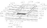
図1は、本発明にかかる壁構造の一実施例における壁材の突き合わせ部分付近の構造を示す斜視説明図である。
図1に示す壁構造では、厚さ14mm、幅910mm、長さ3030mmで、右側端部に実部b912を有し、左側端部に実部b911を有する木繊維補強セメント板B1を壁材として、ポリチオウレタン系目地処理材C1を弾性目地処理材として、厚さ0.4mm、幅50mmで、表面に貫通した開口d1を1cm2あたり5個有するポリエステル製シートD1を網目状体として、アクリル系弾性塗材E1を弾性塗材として用いている。
2枚の木繊維補強セメント板B1、B1は、互いにその側端部を突き合わせた状態で、釘(図示せず)により下地材Aに固定されている。なお、木繊維補強セメント板B1は、右側端部に実部b912を、左側端部に実部b911を有するので、側端部を突き合わせた状態とは、図1に示すように、互いの実部b911、b912が合決りしている状態である。また、図1に示すように、木繊維補強セメント板B1は、表面に、凸部b11と凹部b21からなる凹凸模様を有しており、凹部b21の最深部の深さは、凸部b11の最頂部から3.0mmであり、柄欠損率は11%である。なお、凸部b11及び凹部b21の最大幅は、それぞれ5mmより大きい。更に、木繊維補強セメント板B1は、右側端部の表面には、30mmの幅で、木繊維補強セメント板B1の突き合わせ方向に沿って延びており、凹部b21の最深部よりも1.5mm深い弾性目地処理材充填用凹部b31を有し、左側端部の表面には、30mmの幅で、木繊維補強セメント板B1の突き合わせ方向に沿って延びており、凹部b21の最深部よりも1.5mm深い弾性目地処理材充填用凹部b41を有する。そのため、木繊維補強セメント板B1、B1の互いの側端部を突き合わせた状態では、突き合わせ部分の表面には、弾性目地処理材充填用凹部b31と弾性目地処理材充填用凹部b41により、60mmの幅で、突き合わせ部分に沿って延びた、凹部b21の最深部よりも1.5mm深い空間が形成されている。該空間が弾性目地処理材充填用ポケットであり、該弾性目地処理材充填用ポケットには、ポリチオウレタン系目地処理材C1が充填されている。ポリチオウレタン系目地処理材C1は、該弾性目地処理材充填用ポケットを充填するようにのみ配されている。
弾性目地処理材充填用ポケットを充填しているポリチオウレタン系目地処理材C1の内部には、該弾性目地処理材充填用ポケットの幅より小さい幅のポリエステル製シートD1が配されており、ポリチオウレタン系目地処理材C1を補強している。なお、ポリエステル製シートD1は、表面に、貫通した開口d1を1cm2あたり5個有しているが、開口d1には、ポリチオウレタン系目地処理材C1が充填されている。
また、弾性目地処理材充填用ポケットを充填しているポリチオウレタン系目地処理材C1の表面は、突き合わせられた木繊維補強セメント板B1、B1の凹凸模様と連続するように、凸部c11と凹部c21が設けてあるとともに、高さも揃えられている。
そして、木繊維補強セメント板B1、B1とポリチオウレタン系目地処理材C1の表面は、アクリル系弾性塗材E1で全て覆われており、アクリル系弾性塗材E1の表面には、木繊維補強セメント板B1の凸部b11に起因する凸部e11と、木繊維補強セメント板B1の凹部b21に起因する凹部e21と、ポリチオウレタン系目地処理材C1の凸部c11に起因する凸部と、ポリチオウレタン系目地処理材C1の凹部c21に起因する凹部が形成されている。すなわち、アクリル系弾性塗材E1の表面には、木繊維補強セメント板B1の凹凸模様とポリチオウレタン系目地処理材C1の凹凸模様に起因した凹凸模様が形成されている。なお、アクリル系弾性塗材E1は、2kg/m2以上となるように配されている。そして、木繊維補強セメント板B1の表面を覆うアクリル系弾性塗材E1の表面の高さは、ポリチオウレタン系目地処理材C1の表面を覆うアクリル系弾性塗材E1の表面の高さと揃えてある。すなわち、木繊維補強セメント板B1の凸部b11に起因するアクリル系弾性塗材E1の凸部e11の表面の高さは、ポリチオウレタン系目地処理材C1の凸部c11に起因するアクリル系弾性塗材E1の凸部の表面の高さと揃えてあり、木繊維補強セメント板B1の凹部b21に起因するアクリル系弾性塗材E1の凹部e21の表面の高さは、ポリチオウレタン系目地処理材C1の凹部c21に起因するアクリル系弾性塗材E1の凹部の表面の高さと揃えてある。
よって、図1に示す壁構造によれば、表面がアクリル系弾性塗材E1に被覆されて無目地であるにもかかわらず、該表面は凹凸模様を有することができる。そして、該表面の凹凸模様は、木繊維補強セメント板B1の凹凸模様とポリチオウレタン系目地処理材C1の凹凸模様に起因しており、アクリル系弾性塗材E1の塗装手法によって模様付けされたものではないので、多大な塗装手間代が掛からないとともに、仕上がり意匠のバラツキが小さい。
また、木繊維補強セメント板B1の凹部b21の最深部の深さが凸部b11の最頂部から3.0mmであり、柄欠損率が11%であるので、壁の凹凸模様は木繊維補強セメント板B1の凹凸模様がより反映されて外観が良いとともに、耐候性、耐水性に優れ、壁の強度にも問題は発生しない。
更に、木繊維補強セメント板B1、B1の側端部の突き合わせ部分の表面には、60mmの幅で、突き合わせ部分に沿って延びた、凹部b21の最深部よりも1.5mm深い最深部を有する弾性目地処理材充填用ポケットが形成されており、該弾性目地処理材充填用ポケットには、ポリチオウレタン系目地処理材C1が充填されており、ポリチオウレタン系目地処理材C1の表面は、2kg/m2以上の量のアクリル系弾性塗材E1により被覆されているので、木繊維補強セメント板B1、B1の側端部の突き合わせ部分に十分な量のポリチオウレタン系目地処理材C1が配置され、更にその上に十分な量のアクリル系弾性塗材E1が配置されることとなり、木繊維補強セメント板B1、B1の側端部の突き合わせ部分の経年の伸縮は抑えられ、アクリル系弾性塗材E1にはクラックが生じにくい。
更に、ポリチオウレタン系目地処理材C1の内部には、表面に、貫通した開口d1を1cm2あたり5個有したポリエステル製シートD1が、開口d1にポリチオウレタン系目地処理材C1が充填された状態で配置されているので、ポリチオウレタン系目地処理材C1とポリエステル製シートD1は一体化し、ポリチオウレタン系目地処理材C1が補強されて、木繊維補強セメント板B1、B1の側端部の突き合わせ部分の経年の伸縮はより抑えられ、アクリル系弾性塗材E1にはクラックが更に生じにくい。
更に、ポリチオウレタン系目地処理材C1の表面の高さは、突き合わせられた木繊維補強セメント板B1、B1の表面の高さと揃えられているので、アクリル系弾性塗材E1を塗布する際に、ポリチオウレタン系目地処理材C1を展着した部分が壁の望まない凹凸部とならないように注意を払う必要がなく、作業性が更に向上するとともに、仕上がり意匠のバラツキも更に小さくなり、壁の外観も更に良い。FIG. 1 is a perspective explanatory view showing a structure near a butt portion of a wall material in an embodiment of a wall structure according to the present invention.
In the wall structure shown in FIG. 1, a wood fiber reinforced cement board B1 having a thickness of 14 mm, a width of 910 mm, a length of 3030 mm, a real part b912 at the right end, and a real part b911 at the left end is used as a wall material. A polythiourethane-based joint treatment material C1 is used as an elastic joint treatment material, and a polyester sheet D1 having a thickness of 0.4 mm, a width of 50 mm, and five openings d1 penetrating through the surface per 1 cm2 is used as a mesh. The system elastic coating material E1 is used as the elastic coating material.
The two wood fiber reinforced cement boards B1 and B1 are fixed to the base material A with nails (not shown) in a state in which the side ends thereof are abutted with each other. Since the wood fiber reinforced cement board B1 has a real part b912 at the right end and a real part b911 at the left end, the state in which the side ends are brought into contact with each other as shown in FIG. In this state, the parts b911 and b912 are determined. Moreover, as shown in FIG. 1, the wood fiber reinforced cement board B1 has a concavo-convex pattern consisting of convex portions b11 and concave portions b21 on the surface, and the depth of the deepest portion of the concave portions b21 is the depth of the convex portions b11. It is 3.0 mm from the top, and the pattern defect rate is 11%. The maximum widths of the convex part b11 and the concave part b21 are each larger than 5 mm. Further, the wood fiber reinforced cement board B1 has a width of 30 mm on the surface of the right end portion, extends along the abutting direction of the wood fiber reinforced cement board B1, and is 1.5 mm deeper than the deepest part of the recess b21. It has a recess b31 for filling an elastic joint treatment material, and has a width of 30 mm on the surface of the left end portion and extends along the abutting direction of the wood fiber reinforced cement board B1, and is 1. It has a recess b41 for filling an elastic joint material 5mm deep. Therefore, in a state where the side ends of the wood fiber reinforced cement boards B1 and B1 are abutted against each other, the surface of the abutting portion is provided with an elastic joint treatment material filling recess b31 and an elastic joint treatment material filling recess b41. A space that is 1.5 mm deeper than the deepest part of the recess b <b> 21 is formed in the width and extending along the abutting part. The space is a pocket for filling an elastic joint treatment material, and the pocket for filling the elastic joint treatment material is filled with a polythiourethane joint material C1. The polythiourethane joint material C1 is disposed only to fill the pockets for filling the elastic joint material.
A polyester sheet D1 having a width smaller than the width of the elastic joint treatment material filling pocket is arranged inside the polythiourethane joint treatment material C1 filling the elastic joint treatment material filling pocket. The thiourethane joint material C1 is reinforced. The polyester sheet D1 has five openings d1 penetrating per cm2 on the surface, and the openings d1 are filled with a polythiourethane joint material C1.
Further, the surface of the polythiourethane joint material C1 filling the pocket for filling the elastic joint material is connected to the convex and concave portions c11 so as to be continuous with the concavo-convex pattern of the wood fiber reinforced cement boards B1 and B1 which are abutted. The recess c21 is provided, and the height is also aligned.
The surfaces of the wood fiber reinforced cement boards B1 and B1 and the polythiourethane joint material C1 are all covered with an acrylic elastic coating material E1, and the surface of the acrylic elastic coating material E1 has a wood fiber reinforcement. A convex part e11 resulting from the convex part b11 of the cement board B1, a concave part e21 resulting from the concave part b21 of the wood fiber reinforced cement board B1, and a convex part resulting from the convex part c11 of the polythiourethane joint material C1; A recess due to the recess c21 of the polythiourethane joint material C1 is formed. That is, the surface of the acrylic elastic coating material E1 is provided with a concavo-convex pattern resulting from the concavo-convex pattern of the wood fiber reinforced cement board B1 and the concavo-convex pattern of the polythiourethane joint material C1. The acrylic elastic coating material E1 is arranged to be2 kg / m2 or more. The height of the surface of the acrylic elastic coating material E1 covering the surface of the wood fiber reinforced cement board B1 is aligned with the height of the surface of the acrylic elastic coating material E1 covering the surface of the polythiourethane joint material C1. is there. That is, the height of the surface of the convex part e11 of the acrylic elastic coating material E1 due to the convex part b11 of the wood fiber reinforced cement board B1 is the acrylic elasticity due to the convex part c11 of the polythiourethane joint material C1. The height of the surface of the concave portion e21 of the acrylic elastic coating material E1 caused by the concave portion b21 of the wood fiber reinforced cement board B1 is the same as the height of the surface of the convex portion of the coating material E1. The height of the surface of the concave portion of the acrylic elastic coating material E1 caused by the concave portion c21 of C1 is aligned.
Therefore, according to the wall structure shown in FIG. 1, although the surface is covered with the acrylic elastic coating material E1 and is uncoated, the surface can have an uneven pattern. Then, the uneven pattern on the surface is caused by the uneven pattern of the wood fiber reinforced cement board B1 and the uneven pattern of the polythiourethane joint material C1, and is patterned by the coating method of the acrylic elastic coating material E1. Since it is not a thing, it does not take much labor for painting, and the variation in the finished design is small.
Moreover, since the depth of the deepest part of the recessed part b21 of wood fiber reinforced cement board B1 is 3.0 mm from the top part of the convex part b11, and a pattern defect rate is 11%, the uneven | corrugated pattern of a wall is wood fiber reinforced cement. The uneven pattern of the plate B1 is more reflected and the appearance is good, weather resistance and water resistance are excellent, and no problem occurs in the strength of the wall.
Further, the surface of the abutting portion at the side end portion of the wood fiber reinforced cement boards B1 and B1 has a deepest portion having a width of 60 mm and extending along the abutting portion and 1.5 mm deeper than the deepest portion of the recess b21. A pocket for filling an elastic joint treatment material is formed, and the pocket for filling an elastic joint treatment material is filled with a polythiourethane joint material C1, and the surface of the polythiourethane joint material C1 is: Since it is covered with the acrylic elastic coating material E1 in an amount of2 kg / m2 or more, a sufficient amount of the polythiourethane joint material C1 is provided at the abutting portion of the side ends of the wood fiber reinforced cement boards B1 and B1. In addition, a sufficient amount of the acrylic elastic coating material E1 is disposed thereon, and the aged expansion and contraction of the abutting portions of the side ends of the wood fiber reinforced cement boards B1 and B1 is suppressed. Cracks are unlikely to occur in the ril-based elastic coating material E1.
Furthermore, the inside of the polythiourethane joint material C1 is filled with a polyester sheet D1 having five through-holes d1 per 1 cm2 on the surface, and the polythiourethane joint material C1 is filled in the opening d1. Since the polythiourethane joint material C1 and the polyester sheet D1 are integrated, the polythiourethane joint material C1 is reinforced, and the side ends of the wood fiber reinforced cement boards B1 and B1. The aging expansion and contraction of the butt portion of the part is further suppressed, and the acrylic elastic coating material E1 is more unlikely to crack.
Further, since the surface height of the polythiourethane joint material C1 is aligned with the surface height of the butted wood fiber reinforced cement boards B1 and B1, when the acrylic elastic coating material E1 is applied. In addition, it is not necessary to pay attention so that the portion where the polythiourethane joint material C1 is spread does not become an undesirable uneven portion of the wall, the workability is further improved, and the variation in the finished design is further reduced. The appearance is even better.
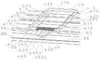
図2は、本発明にかかる壁構造の他の実施例における壁材の突き合わせ部分付近の構造を示す斜視説明図である。
図2に示す壁構造では、厚さ14mm、幅910mm、長さ3030mmで、右側端部に実部b922を有し、左側端部に実部b921を有する木繊維補強セメント板B2を壁材として、ポリチオウレタン系目地処理材C2を弾性目地処理材として、厚さ0.4mm、幅50mmで、表面に貫通した開口d2を1cm2あたり9個有するポリエステル製シートD2を網目状体として、アクリル系弾性塗材E2を弾性塗材として用いている。
2枚の木繊維補強セメント板B2、B2は、互いにその側端部を突き合わせた状態で、釘(図示せず)により下地材Aに固定されている。なお、木繊維補強セメント板B2は右側端部に実部b922を有し、左側端部に実部b921を有するので、側端部を突き合わせた状態とは、図2に示すように、互いの実部b921、b922を合決りさせた状態である。また、図2に示すように、木繊維補強セメント板B2は、表面に、凸部b12と凹部b22からなる凹凸模様を有しており、凹部b22の最深部の深さは、凸部b12の最頂部から3.0mmであり、柄欠損率は11%である。なお、凸部b12及び凹部b22の最大幅は、それぞれ5mmより大きくした。更に、木繊維補強セメント板B2は、右側端部の表面には、10mmの幅で、木繊維補強セメント板B2の突き合わせ方向に沿って延びており、凹部b22の最深部よりも1.5mm深い弾性目地処理材充填用凹部b32を有し、左側端部の表面には、10mmの幅で、木繊維補強セメント板B2の突き合わせ方向に沿って延びており、凹部b22の最深部よりも1.5mm深い弾性目地処理材充填用凹部b42を有する。そのため、木繊維補強セメント板B2、B2の互いの側端部を突き合わせた状態では、突き合わせ部分の表面には、弾性目地処理材充填用凹部b32と弾性目地処理材充填用凹部b42により、20mmの幅で、突き合わせ部分に沿って延びた、凹部b22の最深部よりも1.5mm深い空間が形成されている。該空間が弾性目地処理材充填用ポケットであり、該弾性目地処理材充填用ポケットには、ポリチオウレタン系目地処理材C2が充填されている。そして、ポリチオウレタン系目地処理材C2は、弾性目地処理材充填用ポケットに充填されているとともに、更に木繊維補強セメント板B2、B2の表面の一部をも覆うように配されている。
そして、ポリチオウレタン系目地処理材C2の内部には、ポリエステル製シートD2が配されており、ポリチオウレタン系目地処理材C2を補強している。なお、ポリエステル製シートD2の幅は、弾性目地処理材充填用ポケットの幅よりも大きいので、ポリチオウレタン系目地処理材C2の内部であるとともに、該弾性目地処理材充填用ポケットと木繊維補強セメント板B2、B2の表面の一部をも覆うように配されている。また、ポリエステル製シートD2は、表面に、貫通した開口d2を1cm2あたり9個有しているが、開口d2には、ポリチオウレタン系目地処理材C2が充填されている。
更に、ポリチオウレタン系目地処理材C2の表面には、突き合わせられた木繊維補強セメント板B2、B2の凹凸模様と連続するように、凸部c12と凹部c22が形成されている。
そして、木繊維補強セメント板B2、B2とポリチオウレタン系目地処理材C2の表面は、アクリル系弾性塗材E2で覆われており、アクリル系弾性塗材E2の表面には、木繊維補強セメント板B2の凸部b12に起因する凸部e12と、木繊維補強セメント板B2の凹部b22に起因する凹部e22と、ポリチオウレタン系目地処理材C2の凸部c12に起因する凸部と、ポリチオウレタン系目地処理材C2の凹部c22に起因する凹部が形成されている。すなわち、アクリル系弾性塗材E2の表面には、木繊維補強セメント板B2の凹凸模様とポリチオウレタン系目地処理材C2の凹凸模様に起因した凹凸模様が形成されている。なお、アクリル系弾性塗材E2は、5kg/m2以上となるように配されている。そして、木繊維補強セメント板B2の表面を覆うアクリル系弾性塗材E2の表面の高さは、ポリチオウレタン系目地処理材C2の表面を覆うアクリル系弾性塗材E2の表面の高さと揃えてある。すなわち、木繊維補強セメント板B2の凸部b12に起因するアクリル系弾性塗材E2の凸部e12の表面の高さは、ポリチオウレタン系目地処理材C2の凸部c12に起因するアクリル系弾性塗材E2の凸部の表面の高さと揃えてあり、木繊維補強セメント板B2の凹部b22に起因するアクリル系弾性塗材E2の凹部e22の表面の高さは、ポリチオウレタン系目地処理材C2の凹部c22に起因するアクリル系弾性塗材E2の凹部の表面の高さと揃えてある。
よって、図2に示す壁構造によれば、表面がアクリル系弾性塗材E2に被覆されて無目地であるにもかかわらず、該表面に凹凸模様を有することができる。そして、該表面の凹凸模様は、木繊維補強セメント板B2の凹凸模様とポリチオウレタン系目地処理材C2の凹凸模様に起因しており、アクリル系弾性塗材E2の塗装手法によって模様付けされたものではないので、多大な塗装手間代が掛からないとともに、仕上がり意匠のバラツキが小さい。
また、木繊維補強セメント板B2の凹部b22の最深部の深さが凸部b12の最頂部から3.0mmであり、柄欠損率が11%であるので、壁の凹凸模様は木繊維補強セメント板B2の凹凸模様がより反映されて外観が良いとともに、耐候性、耐水性に優れ、壁の強度にも問題は発生しない。
更に、木繊維補強セメント板B2、B2の側端部の突き合わせ部分の表面には、20mmの幅で、突き合わせ部分に沿って延びた、凹部b22の最深部よりも1.5mm深い最深部を有する弾性目地処理材充填用ポケットが形成されており、該弾性目地処理材充填用ポケットにポリチオウレタン系目地処理材C2が充填されており、ポリチオウレタン系目地処理材C2の表面は、5kg/m2以上の量のアクリル系弾性塗材E2により被覆されているので、木繊維補強セメント板B2、B2の側端部の突き合わせ部分に十分な量のポリチオウレタン系目地処理材C2が配置され、更にその上に十分な量のアクリル系弾性塗材E2が配置されることとなり、木繊維補強セメント板B2、B2の側端部の突き合わせ部分の経年の伸縮は抑えられ、アクリル系弾性塗材E2にはクラックが生じにくい。
更に、ポリチオウレタン系目地処理材C2の内部には、表面に、貫通した開口d2を1cm2あたり9個有したポリエステル製シートD2が、開口d2にポリチオウレタン系目地処理材C2が充填された状態で配置されているので、ポリチオウレタン系目地処理材C2とポリエステル製シートD2は一体化し、ポリチオウレタン系目地処理材C2が補強されて、木繊維補強セメント板B2、B2の側端部の突き合わせ部分の経年の伸縮はより抑えられ、アクリル系弾性塗材E2にはクラックが更に生じにくい。FIG. 2 is an explanatory perspective view showing the structure near the butted portion of the wall material in another embodiment of the wall structure according to the present invention.
In the wall structure shown in FIG. 2, a wood fiber reinforced cement board B2 having a thickness of 14 mm, a width of 910 mm, a length of 3030 mm, a real part b922 at the right end, and a real part b921 at the left end is used as a wall material. The polyester sheet D2 having a thickness of 0.4 mm, a width of 50 mm, and 9 openings d2 penetrating the surface per 1 cm2 is used as an elastic joint material with the polythiourethane joint material C2 as an elastic joint treatment material. The system elastic coating material E2 is used as the elastic coating material.
The two wood fiber reinforced cement boards B2 and B2 are fixed to the base material A with nails (not shown) in a state in which the side ends thereof are abutted with each other. Since the wood fiber reinforced cement board B2 has a real part b922 at the right end and a real part b921 at the left end, the state where the side ends abut each other is as shown in FIG. In this state, the real parts b921 and b922 are agreed. Further, as shown in FIG. 2, the wood fiber reinforced cement board B2 has a concavo-convex pattern consisting of convex portions b12 and concave portions b22 on the surface, and the depth of the deepest portion of the concave portions b22 is the depth of the convex portions b12. It is 3.0 mm from the top, and the pattern defect rate is 11%. In addition, the maximum width of the convex part b12 and the recessed part b22 was made larger than 5 mm, respectively. Further, the wood fiber reinforced cement board B2 has a width of 10 mm on the surface of the right end portion, extends along the abutting direction of the wood fiber reinforced cement board B2, and is 1.5 mm deeper than the deepest part of the recess b22. It has a recess b32 for filling an elastic joint treatment material, and has a width of 10 mm on the surface of the left end portion and extends along the abutting direction of the wood fiber reinforced cement board B2, and is 1. It has a recess b42 for filling an elastic
A polyester sheet D2 is disposed inside the polythiourethane joint material C2 to reinforce the polythiourethane joint material C2. Since the width of the polyester sheet D2 is larger than the width of the pocket for filling the elastic joint treatment material, it is inside the polythiourethane joint treatment material C2, and the pocket for filling the elastic joint treatment material and the wood fiber reinforcement. It arrange | positions so that a part of surface of cement board B2 and B2 may also be covered. The polyester sheet D2 has nine openings d2 penetrating the surface per cm2 , and the openings d2 are filled with a polythiourethane joint material C2.
Furthermore, a convex portion c12 and a concave portion c22 are formed on the surface of the polythiourethane joint material C2 so as to be continuous with the concave and convex patterns of the wood fiber reinforced cement boards B2 and B2 that are abutted.
The surfaces of the wood fiber reinforced cement boards B2 and B2 and the polythiourethane joint material C2 are covered with an acrylic elastic coating material E2, and the surface of the acrylic elastic coating material E2 has a wood fiber reinforced cement. Convex part e12 resulting from convex part b12 of board B2, concave part e22 resulting from concave part b22 of wood fiber reinforced cement board B2, convex part resulting from convex part c12 of polythiourethane joint material C2, poly A concave portion resulting from the concave portion c22 of the thiourethane joint material C2 is formed. That is, the surface of the acrylic elastic coating material E2 is provided with a concavo-convex pattern resulting from the concavo-convex pattern of the wood fiber reinforced cement board B2 and the concavo-convex pattern of the polythiourethane joint material C2. The acrylic elastic coating material E2 is arranged to be 5 kg / m2 or more. The height of the surface of the acrylic elastic coating material E2 covering the surface of the wood fiber reinforced cement board B2 is aligned with the height of the surface of the acrylic elastic coating material E2 covering the surface of the polythiourethane joint material C2. is there. That is, the height of the surface of the convex part e12 of the acrylic elastic coating material E2 due to the convex part b12 of the wood fiber reinforced cement board B2 is the acrylic elasticity due to the convex part c12 of the polythiourethane joint material C2. The height of the surface of the concave portion e22 of the acrylic elastic coating material E2 caused by the concave portion b22 of the wood fiber reinforced cement board B2 is aligned with the height of the surface of the convex portion of the coating material E2. The height of the surface of the concave portion of the acrylic elastic coating material E2 caused by the concave portion c22 of C2 is aligned.
Therefore, according to the wall structure shown in FIG. 2, although the surface is covered with the acrylic elastic coating material E2 and is seamless, it can have an uneven pattern on the surface. And the uneven pattern of this surface originates in the uneven pattern of the wood fiber reinforced cement board B2 and the uneven pattern of the polythiourethane joint material C2, and was patterned by the coating method of the acrylic elastic coating material E2. Since it is not a thing, it does not take much labor for painting, and the variation in the finished design is small.
Further, the depth of the deepest portion of the concave portion b22 of the wood fiber reinforced cement board B2 is 3.0 mm from the topmost portion of the convex portion b12, and the pattern defect rate is 11%. The unevenness pattern of the plate B2 is reflected more and the appearance is good, and the weather resistance and water resistance are excellent, and the wall strength is not problematic.
Furthermore, the surface of the butt portion of the side ends of the wood fiber reinforced cement boards B2 and B2 has a deepest portion having a width of 20 mm and extending along the butt portion and 1.5 mm deeper than the deepest portion of the recess b22. An elastic joint treatment material filling pocket is formed, and the elastic joint treatment material filling pocket is filled with a polythiourethane joint material C2, and the surface of the polythiourethane joint material C2 is 5 kg / because it is covered by m2 or more of the amount of the acrylic elastic coating material E2, a sufficient amount of polythiourethane joint treatment material C2 is disposed in the abutting portion of the side end portions of the wood fiber-reinforced cement boards B2, B2 In addition, a sufficient amount of the acrylic elastic coating material E2 is disposed thereon, and the aged expansion and contraction of the abutting portions of the side ends of the wood fiber reinforced cement boards B2 and B2 is suppressed. Cracks are unlikely to occur in the system elastic coating material E2.
Further, the inside of the polythiourethane joint material C2 is filled with a polyester sheet D2 having nine through-holes d2 per cm2 on the surface, and the polythiourethane joint material C2 is filled in the openings d2. Since the polythiourethane joint material C2 and the polyester sheet D2 are integrated, the polythiourethane joint material C2 is reinforced, and the side ends of the wood fiber reinforced cement boards B2 and B2 The expansion and contraction of the butt portion of the part over time is further suppressed, and the acrylic elastic coating material E2 is more unlikely to crack.
図3は、本発明にかかる壁構造の更に他の実施例における壁材の突き合わせ部分付近の構造を示す斜視説明図である。
図3に示す壁構造では、厚さ14mm、幅910mm、長さ3030mmで、右側端部に実部b932を有し、左側端部に実部b931を有する木繊維補強セメント板B3を壁材として、ポリチオウレタン系目地処理材C3を弾性目地処理材として、厚さ0.4mm、幅50mmで、表面に貫通した開口d3を1cm2あたり5個有するポリエステル製シートD3を網目状体として、アクリル系弾性塗材E3を弾性塗材として用いている。なお、木繊維補強セメント板B3の実部b931、b932の形状は、図1に示す木繊維補強セメント板B1の実部b911、b912とは異なるが、実部b931とb932は、合決りさせることができる。
2枚の木繊維補強セメント板B3、B3は、互いにその側端部を突き合わせた状態で、釘(図示せず)により下地材Aに固定されている。なお、木繊維補強セメント板B3は、右側端部に実部b932を有し、左側端部に実部b931を有するので、側端部を突き合わせた状態とは、図3に示すように、互いの実部b931、b932を合決りさせた状態である。また、図3に示すように、木繊維補強セメント板B3は、表面に、凸部b13と凹部b23からなる凹凸模様を有しており、凹部b23の最深部の深さは、凸部b13の最頂部から3.0mmであり、柄欠損率は11%である。なお、凸部b13及び凹部b23の最大幅は、それぞれ5mmより大きくした。更に、木繊維補強セメント板B3は、右側端部の表面には、40mmの幅で、木繊維補強セメント板B3の突き合わせ方向に沿って延びており、凹部b23の最深部よりも1.8mm深い弾性目地処理材充填用凹部b33を有し、左側端部の表面には、30mmの幅で、木繊維補強セメント板B3の突き合わせ方向に沿って延びており、凹部b23の最深部よりも1.5mm深い弾性目地処理材充填用凹部b43を有する。そのため、木繊維補強セメント板B3、B3の互いの側端部を突き合わせた状態では、突き合わせ部分の表面には、弾性目地処理材充填用凹部b33と弾性目地処理材充填用凹部b43により、60mmの幅で、突き合わせ部分に沿って延びた、凹部b23の最深部よりも1.5〜1.8mm深い空間が形成されている。該空間が弾性目地処理材充填用ポケットである。なお、木繊維補強セメント板B3、B3の互いの側端部を突き合わせた状態では、弾性目地処理材充填用凹部b33の表面の一部は、実部b931の下に配置されるので、該弾性目地処理材充填用ポケットの幅は60mmとなる。そして、ポリチオウレタン系目地処理材C3は、該弾性目地処理材充填用ポケットを充填するようにのみ配されている。
弾性目地処理材充填用ポケットを充填しているポリチオウレタン系目地処理材C3の内部には、該弾性目地処理材充填用ポケットの幅より小さい幅のポリエステル製シートD3が配されており、ポリチオウレタン系目地処理材C3を補強している。なお、ポリエステル製シートD3は、表面に、貫通した開口d3を1cm2あたり5個有しているが、開口d3には、ポリチオウレタン系目地処理材C3が充填されている。
また、弾性目地処理材充填用ポケットを充填しているポリチオウレタン系目地処理材C3の表面には、突き合わせられた木繊維補強セメント板B3、B3の凹凸模様と連続するように、凸部c13と凹部c23が設けてあるとともに、表面の高さも揃えられている。
そして、木繊維補強セメント板B3、B3とポリチオウレタン系目地処理材C3の表面は、アクリル系弾性塗材E3で覆われており、アクリル系弾性塗材E3の表面には、木繊維補強セメント板B3の凸部b13に起因する凸部e13と、木繊維補強セメント板B3の凹部b23に起因する凹部e23と、ポリチオウレタン系目地処理材C3の凸部c13に起因する凸部と、ポリチオウレタン系目地処理材C3の凹部c23に起因する凹部が形成されている。すなわち、アクリル系弾性塗材E3の表面には、木繊維補強セメント板B3の凹凸模様とポリチオウレタン系目地処理材C3の凹凸模様に起因した凹凸模様が形成されている。なお、アクリル系弾性塗材E3は、2kg/m2以上となるように配されている。そして、木繊維補強セメント板B3の表面を覆うアクリル系弾性塗材E3の表面の高さは、ポリチオウレタン系目地処理材C3の表面を覆うアクリル系弾性塗材E3の表面の高さと揃えてある。すなわち、木繊維補強セメント板B3の凸部b13に起因するアクリル系弾性塗材E3の凸部e13の表面の高さは、ポリチオウレタン系目地処理材C3の凸部c13に起因するアクリル系弾性塗材E3の凸部の表面の高さと揃えてあり、木繊維補強セメント板B3の凹部b23に起因するアクリル系弾性塗材E3の凹部e23の表面の高さは、ポリチオウレタン系目地処理材C3の凹部c23に起因するアクリル系弾性塗材E3の凹部の表面の高さと揃えてある。
よって、図3に示す壁構造によれば、表面がアクリル系弾性塗材E3に被覆されて無目地であるにもかかわらず、該表面は凹凸模様を有することができる。そして、該表面の凹凸模様は、木繊維補強セメント板B3の凹凸模様とポリチオウレタン系目地処理材C3の凹凸模様に起因しており、アクリル系弾性塗材E3の塗装手法によって模様付けされたものではないので、多大な塗装手間代が掛からないとともに、仕上がり意匠のバラツキが小さい。
また、木繊維補強セメント板B3の凹部b23の最深部の深さが凸部b13の最頂部から3.0mmであり、柄欠損率が11%であるので、壁の凹凸模様は木繊維補強セメント板B3の凹凸模様がより反映されて外観が良いとともに、耐候性、耐水性に優れ、壁の強度にも問題は発生しない。
更に、木繊維補強セメント板B3、B3の側端部の突き合わせ部分の表面には、60mmの幅で、突き合わせ部分に沿って延びた、凹部b23の最深部よりも1.8mm深い最深部を有する弾性目地処理材充填用ポケットが形成されており、該弾性目地処理材充填用ポケットには、ポリチオウレタン系目地処理材C3が充填されており、ポリチオウレタン系目地処理材C3の表面は、2kg/m2以上の量のアクリル系弾性塗材E3により被覆されているので、木繊維補強セメント板B3、B3の側端部の突き合わせ部分に十分な量のポリチオウレタン系目地処理材C3が配置され、更にその上に十分な量のアクリル系弾性塗材E3が配置されることとなり、木繊維補強セメント板B3、B3の側端部の突き合わせ部分の経年の伸縮は抑えられ、アクリル系弾性塗材E3にはクラックが生じにくい。
更に、ポリチオウレタン系目地処理材C3の内部には、表面に、貫通した開口d3を1cm2あたり5個有したポリエステル製シートD3が、開口d3にポリチオウレタン系目地処理材C3が充填された状態で配置されているので、ポリチオウレタン系目地処理材C3とポリエステル製シートD3は一体化し、ポリチオウレタン系目地処理材C3が補強されて、木繊維補強セメント板B3、B3の側端部の突き合わせ部分の経年の伸縮はより抑えられ、アクリル系弾性塗材E3にはクラックが更に生じにくい。
更に、ポリチオウレタン系目地処理材C3の表面の高さは、突き合わせられた木繊維補強セメント板B3、B3の表面の高さと揃えられているので、アクリル系弾性塗材E3を塗布する際に、ポリチオウレタン系目地処理材C3を展着した部分が壁の望まない凹凸部とならないように注意を払う必要がなく、作業性が更に向上するとともに、仕上がり意匠のバラツキも更に小さくなり、壁の外観も更に良い。FIG. 3 is a perspective explanatory view showing the structure near the butted portion of the wall material in still another embodiment of the wall structure according to the present invention.
In the wall structure shown in FIG. 3, a wood fiber reinforced cement board B3 having a thickness of 14 mm, a width of 910 mm, a length of 3030 mm, a real part b932 at the right end, and a real part b931 at the left end is used as a wall material. A polythiourethane-based joint treatment material C3 is used as an elastic joint treatment material, and a polyester sheet D3 having a thickness of 0.4 mm, a width of 50 mm, and five openings d3 penetrating through the surface per 1 cm2 is used as a mesh-like material. The system elastic coating material E3 is used as the elastic coating material. The shapes of the real parts b931 and b932 of the wood fiber reinforced cement board B3 are different from the real parts b911 and b912 of the wood fiber reinforced cement board B1 shown in FIG. 1, but the real parts b931 and b932 are decided. Can do.
The two wood fiber reinforced cement boards B3 and B3 are fixed to the base material A with nails (not shown) in a state in which the side ends thereof are abutted with each other. Since the wood fiber reinforced cement board B3 has a real part b932 at the right end and a real part b931 at the left end, the state in which the side ends are brought into contact with each other as shown in FIG. The real parts b931 and b932 are settled. Moreover, as shown in FIG. 3, the wood fiber reinforced cement board B3 has a concavo-convex pattern consisting of convex portions b13 and concave portions b23 on the surface, and the depth of the deepest portion of the concave portions b23 is the depth of the convex portions b13. It is 3.0 mm from the top, and the pattern defect rate is 11%. In addition, the maximum width of the convex part b13 and the recessed part b23 was made larger than 5 mm, respectively. Further, the wood fiber reinforced cement board B3 has a width of 40 mm on the surface of the right end portion, extends along the abutting direction of the wood fiber reinforced cement board B3, and is 1.8 mm deeper than the deepest part of the recess b23. It has a recess b33 for filling an elastic joint treatment material, and has a width of 30 mm on the surface of the left end portion and extends along the abutting direction of the wood fiber reinforced cement board B3. It has a recess b43 for filling an elastic
A polyester sheet D3 having a width smaller than the width of the elastic joint treatment material filling pocket is disposed inside the polythiourethane joint material C3 filling the elastic joint treatment pocket. The thiourethane joint material C3 is reinforced. The polyester sheet D3 has five openings d3 penetrating per cm2 on the surface, and the openings d3 are filled with a polythiourethane joint material C3.
Further, the surface of the polythiourethane joint material C3 filling the pockets for filling the elastic joint treatment material C3 has a convex part c13 so as to be continuous with the uneven pattern of the butted wood fiber reinforced cement boards B3 and B3. And a recess c23 are provided, and the height of the surface is also aligned.
The surfaces of the wood fiber reinforced cement boards B3 and B3 and the polythiourethane joint material C3 are covered with an acrylic elastic coating material E3, and the surface of the acrylic elastic coating material E3 has a wood fiber reinforced cement. Convex part e13 resulting from convex part b13 of board B3, Concave part e23 resulting from concave part b23 of wood fiber reinforced cement board B3, Convex part resulting from convex part c13 of polythiourethane joint material C3, A concave portion resulting from the concave portion c23 of the thiourethane joint material C3 is formed. That is, the surface of the acrylic elastic coating material E3 is provided with a concavo-convex pattern resulting from the concavo-convex pattern of the wood fiber reinforced cement board B3 and the concavo-convex pattern of the polythiourethane joint material C3. The acrylic elastic coating material E3 is arranged so as to be2 kg / m2 or more. The height of the surface of the acrylic elastic coating material E3 covering the surface of the wood fiber reinforced cement board B3 is aligned with the height of the surface of the acrylic elastic coating material E3 covering the surface of the polythiourethane joint material C3. is there. That is, the height of the surface of the convex portion e13 of the acrylic elastic coating material E3 due to the convex portion b13 of the wood fiber reinforced cement board B3 is the acrylic elastic due to the convex portion c13 of the polythiourethane joint material C3. The height of the surface of the concave portion e23 of the acrylic elastic coating material E3, which is aligned with the height of the convex portion surface of the coating material E3 and is caused by the concave portion b23 of the wood fiber reinforced cement board B3, is a polythiourethane joint material. The height of the surface of the concave portion of the acrylic elastic coating material E3 caused by the concave portion c23 of C3 is aligned.
Therefore, according to the wall structure shown in FIG. 3, although the surface is covered with the acrylic elastic coating material E3 and is plain, the surface can have an uneven pattern. Then, the uneven pattern on the surface is caused by the uneven pattern of the wood fiber reinforced cement board B3 and the uneven pattern of the polythiourethane joint material C3, and is patterned by the coating method of the acrylic elastic coating material E3. Since it is not a thing, it does not take much labor for painting, and the variation in the finished design is small.
Further, the depth of the deepest portion of the concave portion b23 of the wood fiber reinforced cement board B3 is 3.0 mm from the topmost portion of the convex portion b13, and the pattern defect rate is 11%. The uneven pattern of the plate B3 is more reflected and the appearance is good, weather resistance and water resistance are excellent, and no problem occurs in the strength of the wall.
Furthermore, the surface of the abutting portion at the side end of the wood fiber reinforced cement boards B3 and B3 has a deepest portion that is 60 mm wide and extends along the abutting portion and is 1.8 mm deeper than the deepest portion of the recess b23. A pocket for filling an elastic joint treatment material is formed, and the pocket for filling an elastic joint treatment material is filled with a polythiourethane joint material C3, and the surface of the polythiourethane joint material C3 is Since it is covered with an acrylic elastic coating material E3 in an amount of2 kg / m2 or more, a sufficient amount of polythiourethane joint material C3 is provided at the abutting portion of the side ends of the wood fiber reinforced cement boards B3 and B3. In addition, a sufficient amount of acrylic elastic coating material E3 is disposed thereon, and the aged expansion and contraction of the abutting portions of the side ends of the wood fiber reinforced cement boards B3 and B3 is suppressed. Cracks are unlikely to occur in the ril-based elastic coating material E3.
Further, the inside of the polythiourethane joint material C3 is filled with a polyester sheet D3 having five through-holes d3 per cm2 on the surface, and the polythiourethane joint material C3 is filled in the opening d3. Since the polythiourethane joint material C3 and the polyester sheet D3 are integrated, the polythiourethane joint material C3 is reinforced, and the side ends of the wood fiber reinforced cement boards B3 and B3. The expansion and contraction of the butt portion of the part over time is further suppressed, and the acrylic elastic coating material E3 is more unlikely to crack.
Furthermore, since the surface height of the polythiourethane joint material C3 is aligned with the surface height of the butted wood fiber reinforced cement boards B3 and B3, the acrylic elastic coating material E3 is applied. In addition, it is not necessary to pay attention so that the portion where the polythiourethane joint material C3 is spread does not become an undesired uneven portion of the wall, the workability is further improved, and the variation in the finished design is further reduced. The appearance is even better.
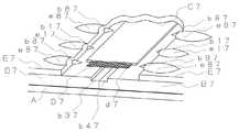
図4は、本発明にかかる壁構造の更に他の実施例における壁材の突き合わせ部分付近の構造を示す斜視説明図である。
図4に示す壁構造では、厚さ14mm、幅910mm、長さ3030mmで、右側端部に実部b942を有し、左側端部にb941を有する木繊維補強セメント板B4を壁材として、ポリチオウレタン系目地処理材C4を弾性目地処理材として、厚さ0.4mm、幅50mmで、表面に貫通した開口d4を1cm2あたり9個有するポリエステル製シートD4を網目状体として、アクリル系弾性塗材E4を弾性塗材として用いている。
2枚の木繊維補強セメント板B4、B4は、互いにその側端部を突き合わせた状態で、釘(図示せず)により下地材Aに固定されている。なお、木繊維補強セメント板B4は右側端部に実部b942を有し、左側端部にb941を有するので、側端部を突き合わせた状態とは、図4に示すように、互いの実部b941、b942を合決りさせた状態である。また、図4に示すように、木繊維補強セメント板B4は、表面に、凸部b14と凹部b24からなる凹凸模様を有しており、凹部b24の最深部の深さは、凸部b14の最頂部から3.0mmであり、柄欠損率は11%である。なお、凸部b14及び凹部b24の最大幅は、それぞれ5mmより大きくした。更に、木繊維補強セメント板B4は、右側端部の表面には、10mmの幅で、木繊維補強セメント板B4の内側から傾斜をなしており、木繊維補強セメント板B4の突き合わせ方向に沿って延びており、最深部が凹部b24の最深部よりも1.5mm深い弾性目地処理材充填用傾斜部b54を有し、左側端部の表面には、10mmの幅で、木繊維補強セメント板B4の内側から傾斜をなしており、木繊維補強セメント板B4の突き合わせ方向に沿って延びており、最深部が凹部b24の最深部よりも1.5mm深い弾性目地処理材充填用傾斜部b64を有する。そのため、木繊維補強セメント板B4、B4の互いの側端部を突き合わせた状態では、突き合わせ部分の表面には、弾性目地処理材充填用傾斜部b54と弾性目地処理材充填用傾斜部b64により、20mmの幅で、突き合わせ部分に沿って延びた、凹部b24の最深部よりも1.5mm深い最深部を有する空間が形成されている。該空間が弾性目地処理材充填用ポケットであり、該弾性目地処理材充填用ポケットには、ポリチオウレタン系目地処理材C4が充填されている。そして、ポリチオウレタン系目地処理材C4は、弾性目地処理材充填用ポケットに充填されているとともに、更に木繊維補強セメント板B4、B4の表面の一部をも覆うように配されている。
そして、ポリチオウレタン系目地処理材C4の内部には、ポリエステル製シートD4が配されており、ポリチオウレタン系目地処理材C4を補強している。なお、ポリエステル製シートD4の幅は、弾性目地処理材充填用ポケットの幅よりも大きいので、ポリチオウレタン系目地処理材C4の内部であるとともに、該弾性目地処理材充填用ポケットと木繊維補強セメント板B4、B4の表面の一部をも覆うように配されている。また、ポリエステル製シートD4は、表面に、貫通した開口d4を1cm2あたり9個有しているが、開口d4には、ポリチオウレタン系目地処理材C4が充填されている。
更に、ポリチオウレタン系目地処理材C4の表面には、突き合わせられた木繊維補強セメント板B4、B4の凹凸模様と連続するように、凸部c14と凹部c24が設けてある。
そして、木繊維補強セメント板B4、B4とポリチオウレタン系目地処理材C4の表面は、アクリル系弾性塗材E4で覆われており、アクリル系弾性塗材E4の表面には、木繊維補強セメント板B4の凸部b14に起因する凸部e14と、木繊維補強セメント板B4の凹部b24に起因する凹部e24と、ポリチオウレタン系目地処理材C4の凸部c14に起因する凸部と、ポリチオウレタン系目地処理材C4の凹部c24に起因する凹部が形成されている。すなわち、アクリル系弾性塗材E4の表面には、木繊維補強セメント板B4の凹凸模様とポリチオウレタン系目地処理材C4の凹凸模様に起因した凹凸模様が形成されている。なお、アクリル系弾性塗材E4は、5kg/m2以上となるように配されている。そして、木繊維補強セメント板B4の表面を覆うアクリル系弾性塗材E4の表面の高さは、ポリチオウレタン系目地処理材C4の表面を覆うアクリル系弾性塗材E4の表面の高さと揃えてある。すなわち、木繊維補強セメント板B4の凸部b14に起因するアクリル系弾性塗材E4の凸部e14の表面の高さは、ポリチオウレタン系目地処理材C4の凸部c14に起因するアクリル系弾性塗材E4の凸部の表面の高さと揃えてあり、木繊維補強セメント板B4の凹部b24に起因するアクリル系弾性塗材E4の凹部e24の表面の高さは、ポリチオウレタン系目地処理材C4の凹部c24に起因するアクリル系弾性塗材E4の凹部の表面の高さと揃えてある。
よって、図4に示す壁構造によれば、表面がアクリル系弾性塗材E4に被覆されて無目地であるにもかかわらず、該表面は凹凸模様を有することができる。そして、該表面の凹凸模様は、木繊維補強セメント板B4の凹凸模様とポリチオウレタン系目地処理材C4の凹凸模様に起因しており、アクリル系弾性塗材E4の塗装手法によって模様付けされたものではないので、多大な塗装手間代が掛からないとともに、仕上がり意匠のバラツキが小さい。
また、木繊維補強セメント板B4の凹部b24の最深部の深さが凸部b14の最頂部から3.0mmであり、柄欠損率が11%であるので、壁の凹凸模様は木繊維補強セメント板B4の凹凸模様がより反映されて外観が良いとともに、耐候性、耐水性に優れ、壁の強度にも問題は発生しない。
更に、木繊維補強セメント板B4、B4の側端部の突き合わせ部分の表面には、20mmの幅で、突き合わせ部分に沿って延びた、凹部b24の最深部よりも1.5mm深い最深部を有する弾性目地処理材充填用ポケットが形成されており、該弾性目地処理材充填用ポケットには、ポリチオウレタン系目地処理材C4が充填されており、ポリチオウレタン系目地処理材C4の表面は、5kg/m2以上の量のアクリル系弾性塗材E4により被覆されているので、木繊維補強セメント板B4、B4の側端部の突き合わせ部分に十分な量のポリチオウレタン系目地処理材C4が配置され、更にその上に十分な量のアクリル系弾性塗材E4が配置されることとなり、木繊維補強セメント板B4、B4の側端部の突き合わせ部分の経年の伸縮は抑えられ、アクリル系弾性塗材E4にはクラックが生じにくい。
更に、ポリチオウレタン系目地処理材C4の内部には、表面に、貫通した開口d4を1cm2あたり9個有したポリエステル製シートD4が、開口d4にポリチオウレタン系目地処理材C4が充填された状態で配置されているので、ポリチオウレタン系目地処理材C4とポリエステル製シートD4は一体化し、ポリチオウレタン系目地処理材C4が補強されて、木繊維補強セメント板B4、B4の側端部の突き合わせ部分の経年の伸縮はより抑えられ、アクリル系弾性塗材E4にはクラックが更に生じにくい。FIG. 4 is a perspective explanatory view showing the structure in the vicinity of the butted portion of the wall material in still another embodiment of the wall structure according to the present invention.
In the wall structure shown in FIG. 4, a wood fiber reinforced cement board B4 having a thickness of 14 mm, a width of 910 mm, a length of 3030 mm, a real part b942 at the right end, and b941 at the left end is used as a wall material. A thiourethane-based joint treatment material C4 is used as an elastic joint treatment material, and a polyester sheet D4 having a thickness of 0.4 mm, a width of 50 mm, and nine openings d4 penetrating the surface per 1 cm2 is used as a mesh-like body, and acrylic elastic. The coating material E4 is used as an elastic coating material.
The two wood fiber reinforced cement boards B4 and B4 are fixed to the base material A with nails (not shown) in a state in which the side ends thereof are abutted with each other. Since the wood fiber reinforced cement board B4 has a real part b942 at the right end and b941 at the left end, the state where the side ends are abutted with each other is as shown in FIG. In this state, b941 and b942 are decided. Moreover, as shown in FIG. 4, the wood fiber reinforced cement board B4 has a concavo-convex pattern consisting of convex portions b14 and concave portions b24 on the surface, and the depth of the deepest portion of the concave portions b24 is the depth of the convex portions b14. It is 3.0 mm from the top, and the pattern defect rate is 11%. In addition, the maximum width of the convex part b14 and the recessed part b24 was made larger than 5 mm, respectively. Further, the wood fiber reinforced cement board B4 has a width of 10 mm on the surface of the right end portion, and is inclined from the inside of the wood fiber reinforced cement board B4, along the abutting direction of the wood fiber reinforced cement board B4. It has an inclined portion b54 for filling an elastic joint treatment material, the deepest part being 1.5 mm deeper than the deepest part of the recess b24, and the surface of the left end has a width of 10 mm and is made of wood fiber reinforced cement board B4. Is inclined along the direction of butting of the wood fiber reinforced cement board B4, and the deepest portion has an inclined portion b64 for filling the elastic joint material, which is 1.5 mm deeper than the deepest portion of the recess b24. . Therefore, in the state where the side ends of the wood fiber reinforced cement boards B4 and B4 are abutted with each other, the surface of the abutting portion is provided with an elastic joint treatment material filling inclined portion b54 and an elastic joint treatment material filling inclined portion b64. A space having a deepest part 1.5 mm deeper than the deepest part of the recess b24 is formed with a width of 20 mm and extending along the abutting part. The space is an elastic joint treatment material filling pocket, and the elastic joint treatment material filling pocket is filled with a polythiourethane joint material C4. The polythiourethane joint material C4 is filled in the elastic joint treatment material filling pocket, and is further disposed so as to cover part of the surface of the wood fiber reinforced cement boards B4 and B4.
A polyester sheet D4 is arranged inside the polythiourethane joint material C4 to reinforce the polythiourethane joint material C4. Since the width of the polyester sheet D4 is larger than the width of the pocket for filling the elastic joint material, it is inside the polythiourethane joint material C4, and the elastic joint material filling pocket and the wood fiber reinforcement. It arrange | positions so that a part of surface of cement board B4 and B4 may also be covered. Further, the polyester sheet D4 has nine through-holes d4 per cm2 on its surface, and the openings d4 are filled with a polythiourethane joint material C4.
Furthermore, a convex portion c14 and a concave portion c24 are provided on the surface of the polythiourethane joint material C4 so as to be continuous with the concavo-convex pattern of the butted wood fiber reinforced cement boards B4 and B4.
The surfaces of the wood fiber reinforced cement boards B4 and B4 and the polythiourethane joint material C4 are covered with an acrylic elastic coating material E4, and the surface of the acrylic elastic coating material E4 has a wood fiber reinforced cement. Convex part e14 resulting from convex part b14 of board B4, Concave part e24 resulting from concave part b24 of wood fiber reinforced cement board B4, Convex part resulting from convex part c14 of polythiourethane joint material C4, A concave portion resulting from the concave portion c24 of the thiourethane joint material C4 is formed. That is, the surface of the acrylic elastic coating material E4 is provided with a concavo-convex pattern resulting from the concavo-convex pattern of the wood fiber reinforced cement board B4 and the concavo-convex pattern of the polythiourethane joint material C4. The acrylic elastic coating material E4 is arranged to be 5 kg / m2 or more. The height of the surface of the acrylic elastic coating material E4 covering the surface of the wood fiber reinforced cement board B4 is aligned with the height of the surface of the acrylic elastic coating material E4 covering the surface of the polythiourethane joint material C4. is there. That is, the height of the surface of the convex part e14 of the acrylic elastic coating material E4 due to the convex part b14 of the wood fiber reinforced cement board B4 is the acrylic elastic due to the convex part c14 of the polythiourethane joint material C4. The height of the surface of the concave portion e24 of the acrylic elastic coating material E4, which is aligned with the height of the convex portion surface of the coating material E4 and is caused by the concave portion b24 of the wood fiber reinforced cement board B4, is a polythiourethane joint material. The height of the surface of the concave portion of the acrylic elastic coating material E4 caused by the concave portion c24 of C4 is aligned.
Therefore, according to the wall structure shown in FIG. 4, although the surface is covered with the acrylic elastic coating material E4 and is plain, the surface can have an uneven pattern. And the uneven pattern of this surface originates in the uneven pattern of the wood fiber reinforced cement board B4 and the uneven pattern of the polythiourethane joint material C4, and was patterned by the coating method of the acrylic elastic coating material E4. Since it is not a thing, it does not take much labor for painting, and the variation in the finished design is small.
Further, the depth of the deepest portion of the concave portion b24 of the wood fiber reinforced cement board B4 is 3.0 mm from the topmost portion of the convex portion b14, and the pattern defect rate is 11%. The uneven pattern of the plate B4 is reflected more and the appearance is good, and the weather resistance and water resistance are excellent, and there is no problem in the strength of the wall.
Further, the surface of the butt portion of the side end portion of the wood fiber reinforced cement board B4, B4 has a deepest portion having a width of 20 mm and extending along the butt portion and 1.5 mm deeper than the deepest portion of the recess b24. A pocket for filling an elastic joint treatment material is formed, and the pocket for filling an elastic joint treatment material is filled with a polythiourethane joint material C4, and the surface of the polythiourethane joint material C4 is Since it is covered with an acrylic elastic coating material E4 in an amount of 5 kg / m2 or more, a sufficient amount of polythiourethane joint material C4 is provided at the abutting portion of the side ends of the wood fiber reinforced cement boards B4 and B4. In addition, a sufficient amount of the acrylic elastic coating material E4 is disposed thereon, and the aged expansion and contraction of the butt portion of the side ends of the wood fiber reinforced cement boards B4 and B4 is suppressed. Cracks are unlikely to occur in the ril-based elastic coating material E4.
Further, the inside of the polythiourethane joint material C4 is filled with a polyester sheet D4 having nine through-hole openings d4 per 1 cm2 on the surface, and the polythiourethane joint material C4 is filled in the openings d4. Since the polythiourethane joint material C4 and the polyester sheet D4 are integrated, the polythiourethane joint material C4 is reinforced, and the side ends of the wood fiber reinforced cement boards B4 and B4. The expansion and contraction of the butt portion of the portion over time is further suppressed, and the acrylic elastic coating material E4 is more unlikely to crack.
図5は、本発明にかかる壁構造の更に他の実施例における壁材の突き合わせ部分付近の構造を示す斜視説明図である。
図5に示す壁構造では、厚さ14mm、幅910mm、長さ3030mmで、右側端部に実部b952を有し、左側端部に実部b951を有する木繊維補強セメント板B5を壁材として、ポリチオウレタン系目地処理材C5を弾性目地処理材として、厚さ0.4mm、幅50mmで、表面に貫通した開口d5を1cm2あたり9個有するポリエステル製シートD5を網目状体として、アクリル系弾性塗材E5を弾性塗材として用いている。
2枚の木繊維補強セメント板B5、B5は、互いにその側端部を突き合わせた状態で、釘(図示せず)により下地材Aに固定されている。なお、木繊維補強セメント板B5は、右側端部に実部b952を有し、左側端部に実部b951を有するので、側端部を突き合わせた状態とは、図5に示すように、互いの実部b951、b952を合決りさせた状態である。また、図5に示すように、木繊維補強セメント板B5は、表面に、凸部b15と凹部b25からなる凹凸模様を有しており、凹部b25の最深部の深さは、凸部b15の最頂部から3.0mmであり、柄欠損率は11%である。なお、凸部b15及び凹部b25の最大幅は、それぞれ5mmより大きくした。更に、木繊維補強セメント板B5は、右側端部の表面には、10mmの幅で、木繊維補強セメント板B5の突き合わせ方向に沿って延びており、凹部b25の最深部よりも1.5mm深い弾性目地処理材充填用凹部b35と、10mmの幅で、木繊維補強セメント板B5の突き合わせ方向に沿って延びており、弾性目地処理材充填用凹部b35から木繊維補強セメント板B5の内側に向かって傾斜をなしている弾性目地処理材充填用傾斜部b55を有する。一方、左側端部の表面には、10mmの幅で、木繊維補強セメント板B5の突き合わせ方向に沿って延びており、凹部b25の最深部よりも1.5mm深い弾性目地処理材充填用凹部b45と、10mmの幅で、木繊維補強セメント板B5の突き合わせ方向に沿って延びており、弾性目地処理材充填用凹部b45から木繊維補強セメント板B5の内側に向かって傾斜をなしている弾性目地処理材充填用傾斜部b65を有する。そのため、木繊維補強セメント板B5、B5の互いの側端部を突き合わせた状態では、突き合わせ部分の表面には、弾性目地処理材充填用凹部b35と、弾性目地処理材充填用凹部b45と、弾性目地処理材充填用傾斜部b55と、弾性目地処理材充填用傾斜部b65により、40mmの幅で、突き合わせ部分に沿って延びた、凹部b25の最深部よりも1.5mm深い最深部を有する空間が形成されている。該空間が弾性目地処理材充填用ポケットであり、該弾性目地処理材充填用ポケットには、ポリチオウレタン系目地処理材C5が充填されている。そして、ポリチオウレタン系目地処理材C5は、弾性目地処理材充填用ポケットに充填されているとともに、更に木繊維補強セメント板B5、B5の表面の一部をも覆うように配されている。
そして、ポリチオウレタン系目地処理材C5の内部には、ポリエステル製シートD5が配されており、ポリチオウレタン系目地処理材C5を補強している。なお、ポリエステル製シートD5の幅は、弾性目地処理材充填用ポケットの幅よりも大きいので、ポリチオウレタン系目地処理材C5の内部であるとともに、該弾性目地処理材充填用ポケットと木繊維補強セメント板B5、B5の表面の一部をも覆うように配されている。また、ポリエステル製シートD5は、表面に、貫通した開口d5を1cm2あたり9個有しているが、開口d5には、ポリチオウレタン系目地処理材C5が充填されている。
更に、ポリチオウレタン系目地処理材C5の表面には、突き合わせられた木繊維補強セメント板B5、B5の凹凸模様と連続するように、凸部c15と凹部c25が設けてある。
そして、木繊維補強セメント板B5、B5とポリチオウレタン系目地処理材C5の表面は、アクリル系弾性塗材E5で覆われている。そのため、アクリル系弾性塗材E5の表面には、木繊維補強セメント板B5の凸部b15に起因する凸部e15と、木繊維補強セメント板B5の凹部b25に起因する凹部e25と、ポリチオウレタン系目地処理材C5の凸部c15に起因する凸部と、ポリチオウレタン系目地処理材C5の凹部c25に起因する凹部が形成されている。すなわち、アクリル系弾性塗材E5の表面には、木繊維補強セメント板B5の凹凸模様とポリチオウレタン系目地処理材C5の凹凸模様に起因した凹凸模様が形成されている。なお、アクリル系弾性塗材E5は、5kg/m2以上となるように配されている。そして、木繊維補強セメント板B5の表面を覆うアクリル系弾性塗材E5の表面の高さは、ポリチオウレタン系目地処理材C5の表面を覆うアクリル系弾性塗材E5の表面の高さと揃えてある。
よって、図5に示す壁構造によれば、表面がアクリル系弾性塗材E5に被覆されて無目地であるにもかかわらず、該表面に凹凸模様を有することができる。そして、該表面の凹凸模様は、木繊維補強セメント板B5の凹凸模様とポリチオウレタン系目地処理材C5の凹凸模様に起因しており、アクリル系弾性塗材E5の塗装手法によって模様付けされたものではないので、多大な塗装手間代が掛からないとともに、仕上がり意匠のバラツキが小さい。
また、木繊維補強セメント板B5の凹部b25の最深部の深さが凸部b15の最頂部から3.0mmであり、柄欠損率が11%であるので、壁の凹凸模様は木繊維補強セメント板B5の凹凸模様がより反映されて外観が良いとともに、耐候性、耐水性に優れ、壁の強度にも問題は発生しない。
更に、木繊維補強セメント板B5、B5の側端部の突き合わせ部分の表面には、40mmの幅で、突き合わせ部分に沿って延びた、凹部b25の最深部よりも1.5mm深い最深部を有する弾性目地処理材充填用ポケットが形成されており、該弾性目地処理材充填用ポケットにポリチオウレタン系目地処理材C5が充填されており、ポリチオウレタン系目地処理材C5の表面は、5kg/m2以上の量のアクリル系弾性塗材E5により被覆されているので、木繊維補強セメント板B5、B5の側端部の突き合わせ部分に十分な量のポリチオウレタン系目地処理材C5が配置され、更にその上に十分な量のアクリル系弾性塗材E5が配置されることとなり、木繊維補強セメント板B5、B5の側端部の突き合わせ部分の経年の伸縮は抑えられ、アクリル系弾性塗材E5にはクラックが生じにくい。
更に、ポリチオウレタン系目地処理材C5の内部には、表面に、貫通した開口d5を1cm2あたり9個有したポリエステル製シートD5が、開口d5にポリチオウレタン系目地処理材C5が充填された状態で配置されているので、ポリチオウレタン系目地処理材C5とポリエステル製シートD5は一体化し、ポリチオウレタン系目地処理材C5が補強されて、木繊維補強セメント板B5、B5の側端部の突き合わせ部分の経年の伸縮はより抑えられ、アクリル系弾性塗材E5にはクラックが更に生じにくい。FIG. 5 is a perspective explanatory view showing the structure near the butted portion of the wall material in still another embodiment of the wall structure according to the present invention.
In the wall structure shown in FIG. 5, a wood fiber reinforced cement board B5 having a thickness of 14 mm, a width of 910 mm, a length of 3030 mm, a real part b952 at the right end, and a real part b951 at the left end is used as a wall material. A polythiourethane-based joint treatment material C5 is used as an elastic joint treatment material, and a polyester sheet D5 having a thickness of 0.4 mm, a width of 50 mm, and nine openings d5 penetrating the surface per 1 cm2 is used as a mesh. The system elastic coating material E5 is used as the elastic coating material.
The two wood fiber reinforced cement boards B5 and B5 are fixed to the base material A with nails (not shown) in a state in which the side ends thereof are abutted with each other. Since the wood fiber reinforced cement board B5 has a real part b952 at the right end and a real part b951 at the left end, the state in which the side ends are brought into contact with each other as shown in FIG. The real parts b951 and b952 of FIG. Further, as shown in FIG. 5, the wood fiber reinforced cement board B5 has a concavo-convex pattern consisting of convex portions b15 and concave portions b25 on the surface, and the depth of the deepest portion of the concave portions b25 is the depth of the convex portions b15. It is 3.0 mm from the top, and the pattern defect rate is 11%. In addition, the maximum width of the convex part b15 and the recessed part b25 was made larger than 5 mm, respectively. Further, the wood fiber reinforced cement board B5 has a width of 10 mm on the surface of the right end portion, extends along the abutting direction of the wood fiber reinforced cement board B5, and is 1.5 mm deeper than the deepest part of the recess b25. The elastic joint treatment material filling recess b35 has a width of 10 mm and extends along the abutting direction of the wood fiber reinforced cement board B5, and extends from the elastic joint treatment material filling recess b35 to the inside of the wood fiber reinforcement cement board B5. And has an inclined portion b55 for filling an elastic joint treatment material. On the other hand, the left end surface has a width of 10 mm, extends along the abutting direction of the wood fiber reinforced cement board B5, and is 1.5 mm deeper than the deepest part of the recessed part b25. And an elastic joint having a width of 10 mm and extending along the abutting direction of the wood fiber reinforced cement board B5, and being inclined from the elastic joint treatment material filling recess b45 toward the inside of the wood fiber reinforced cement board B5. A treatment material filling inclined portion b65 is provided. Therefore, in a state in which the side ends of the wood fiber reinforced cement boards B5 and B5 are abutted against each other, the surface of the abutting portion has an elastic joint treatment material filling recess b35, an elastic joint treatment material filling recess b45, and an elasticity. A space having a deepest part 1.5 mm deeper than the deepest part of the recess b25 and extending along the abutting part, with a width of 40 mm, by the jointing material filling inclined part b55 and the elastic jointing material filling inclined part b65. Is formed. The space is a pocket for filling an elastic joint treatment material, and the pocket for filling an elastic joint treatment material is filled with a polythiourethane joint material C5. The polythiourethane joint material C5 is filled in the elastic joint material filling pocket, and is further disposed so as to cover part of the surface of the wood fiber reinforced cement boards B5 and B5.
A polyester sheet D5 is disposed inside the polythiourethane joint material C5 to reinforce the polythiourethane joint material C5. Since the width of the polyester sheet D5 is larger than the width of the pocket for filling the elastic joint treatment material, it is inside the polythiourethane joint treatment material C5, and the pocket for filling the elastic joint treatment material and the wood fiber reinforcement. It arrange | positions so that a part of surface of cement board B5 and B5 may also be covered. Further, the polyester sheet D5 has nine through-holes d5 per cm2 on its surface, and the openings d5 are filled with a polythiourethane joint material C5.
Further, a convex portion c15 and a concave portion c25 are provided on the surface of the polythiourethane joint material C5 so as to be continuous with the concavo-convex pattern of the butted wood fiber reinforced cement boards B5 and B5.
The surfaces of the wood fiber reinforced cement boards B5 and B5 and the polythiourethane joint material C5 are covered with an acrylic elastic coating material E5. Therefore, on the surface of the acrylic elastic coating material E5, a convex part e15 caused by the convex part b15 of the wood fiber reinforced cement board B5, a concave part e25 caused by the concave part b25 of the wood fiber reinforced cement board B5, and polythiourethane The convex part resulting from the convex part c15 of the system joint treatment material C5 and the concave part resulting from the concave part c25 of the polythiourethane joint process material C5 are formed. That is, the concavo-convex pattern resulting from the concavo-convex pattern of the wood fiber reinforced cement board B5 and the concavo-convex pattern of the polythiourethane joint material C5 is formed on the surface of the acrylic elastic coating material E5. The acrylic elastic coating material E5 is arranged to be 5 kg / m2 or more. The height of the surface of the acrylic elastic coating material E5 covering the surface of the wood fiber reinforced cement board B5 is aligned with the height of the surface of the acrylic elastic coating material E5 covering the surface of the polythiourethane joint material C5. is there.
Therefore, according to the wall structure shown in FIG. 5, although the surface is covered with the acrylic elastic coating material E5 and has no joints, the surface can have an uneven pattern. And the uneven pattern of this surface originates in the uneven pattern of the wood fiber reinforced cement board B5 and the uneven pattern of the polythiourethane joint material C5, and was patterned by the coating method of the acrylic elastic coating material E5. Since it is not a thing, it does not take much labor for painting, and the variation in the finished design is small.
Further, the depth of the deepest part of the concave part b25 of the wood fiber reinforced cement board B5 is 3.0 mm from the top part of the convex part b15 and the pattern defect rate is 11%. The uneven pattern of the plate B5 is more reflected and the appearance is good, and the weather resistance and water resistance are excellent, and the wall strength is not problematic.
Furthermore, the surface of the butt portion of the side end portion of the wood fiber reinforced cement boards B5 and B5 has a deepest portion having a width of 40 mm and extending along the butt portion and 1.5 mm deeper than the deepest portion of the recess b25. A pocket for filling an elastic joint treatment material is formed, and the pocket for filling the elastic joint treatment material is filled with a polythiourethane joint material C5. The surface of the polythiourethane joint material C5 is 5 kg / since m2 or more in an amount of is covered with the acrylic elastic coating material E5, wood fiber reinforced cement boards B5, polythiourethane joint treatment material C5 sufficient amount in the abutting portion of the side end portions of the B5 is arranged In addition, a sufficient amount of the acrylic elastic coating material E5 is disposed on it, and the expansion and contraction of the abutting portions of the side ends of the wood fiber reinforced cement boards B5 and B5 can be suppressed. Cracks are unlikely to occur in the system elastic coating material E5.
Further, the inside of the polythiourethane joint material C5 is filled with a polyester sheet D5 having nine through-holes d5 per cm2 on the surface, and the polythiourethane joint material C5 is filled in the openings d5. Since the polythiourethane joint material C5 and the polyester sheet D5 are integrated, the polythiourethane joint material C5 is reinforced, and the side ends of the wood fiber reinforced cement boards B5 and B5. The expansion and contraction of the butt portion of the portion over time is further suppressed, and the acrylic elastic coating material E5 is more unlikely to crack.
図6は、壁構造の参考例における壁材の突き合わせ部分付近の構造を示す斜視説明図である。
図6に示す壁構造では、厚さ14mm、幅910mm、長さ3030mmで、側端部に実部を有さない木繊維補強セメント板B6を壁材として、ポリチオウレタン系目地処理材C6を弾性目地処理材として、厚さ0.4mm、幅50mmで、表面に貫通した開口d6を1cm2あたり5個有するポリエステル製シートD6を網目状体として、アクリル系弾性塗材E6を弾性塗材として用いている。
2枚の木繊維補強セメント板B6、B6は、互いにその側端部を突き合わせた状態で、釘(図示せず)により下地材Aに固定されている。なお、図6に示すように、木繊維補強セメント板B6は、表面に、凹部b26と凹部b76と平面部からなる、柄欠損率が4%である凹凸模様を有している。そして、凹部b76は凹部b26よりも深く、凹部b76の最深部の深さは、木繊維補強セメント板B6の平面部から3.0mmである。すなわち、木繊維補強セメント板B6の凹凸模様は、凹部b26と凹部b76と平面部とからなるので、木繊維補強セメント板B6の最頂部は平面部となる。なお、凹部b26と凹部b76の最大幅は、それぞれ5mmより大きくした。更に、木繊維補強セメント板B6は、右側端部の表面には、30mmの幅で、木繊維補強セメント板B6の突き合わせ方向に沿って延びており、凹部b76の最深部よりも1.5mm深い弾性目地処理材充填用凹部b36を有し、左側端部の表面には、30mmの幅で、木繊維補強セメント板B6の突き合わせ方向に沿って延びており、凹部b76の最深部よりも1.5mm深い弾性目地処理材充填用凹部b46を有する。そのため、木繊維補強セメント板B6、B6の互いの側端部を突き合わせた状態では、突き合わせ部分の表面には、弾性目地処理材充填用凹部b36と弾性目地処理材充填用凹部b46により、60mmの幅で、突き合わせ部分に沿って延びた、凹部b76の最深部よりも1.5mm深い空間が形成されている。該空間が弾性目地処理材充填用ポケットであり、該弾性目地処理材充填用ポケットには、ポリチオウレタン系目地処理材C6が充填されている。そして、ポリチオウレタン系目地処理材C6は、該弾性目地処理材充填用ポケットを充填するようにのみ配されている。
弾性目地処理材充填用ポケットを充填しているポリチオウレタン系目地処理材C6の内部には、該弾性目地処理材充填用ポケットの幅より小さい幅のポリエステル製シートD6が配されており、ポリチオウレタン系目地処理材C6を補強している。なお、ポリエステル製シートD6は、表面に、貫通した開口d6を1cm2あたり5個有しているが、開口d6には、ポリチオウレタン系目地処理材C6が充填されている。
また、弾性目地処理材充填用ポケットを充填しているポリチオウレタン系目地処理材C6の表面は平面であるが、表面の高さは、突き合わせられた木繊維補強セメント板B6、B6の表面の高さと揃えられている。
そして、木繊維補強セメント板B6、B6とポリチオウレタン系目地処理材C6の表面は、アクリル系弾性塗材E6で全て覆われており、アクリル系弾性塗材E6の表面には、木繊維補強セメント板B6の凹部b26に起因する凹部e26と、木繊維補強セメント板B6の凹部b76に起因する凹部e76が形成されている。すなわち、アクリル系弾性塗材E6の表面には、木繊維補強セメント板B6の凹凸模様に起因した凹凸模様が形成されている。なお、アクリル系弾性塗材E6は、2kg/m2以上となるように配されている。そして、木繊維補強セメント板B6の表面を覆うアクリル系弾性塗材E6の表面の高さは、ポリチオウレタン系目地処理材C6の表面を覆うアクリル系弾性塗材E6の表面の高さと揃えてある。すなわち、木繊維補強セメント板B6の平面部に起因するアクリル系弾性塗材E6の表面の高さは、ポリチオウレタン系目地処理材C6の平面部に起因するアクリル系弾性塗材E6の表面の高さと揃えてある。
よって、図6に示す壁構造によれば、表面がアクリル系弾性塗材E6に被覆されて無目地であるにもかかわらず、該表面は凹凸模様を有することができる。そして、該表面の凹凸模様は、木繊維補強セメント板B6の凹凸模様に起因しており、アクリル系弾性塗材E6の塗装手法によって模様付けされたものではないので、多大な塗装手間代が掛からないとともに、仕上がり意匠のバラツキが小さい。
また、木繊維補強セメント板B6の凹部b76の最深部の深さが平面部から3.0mmであり、柄欠損率が4%であるので、壁の凹凸模様は木繊維補強セメント板B6の凹凸模様がより反映されて外観が良いとともに、耐候性、耐水性に優れ、壁の強度にも問題は発生しない。
更に、木繊維補強セメント板B6、B6の側端部の突き合わせ部分の表面には、60mmの幅で、突き合わせ部分に沿って延びた、凹部b76の最深部よりも1.5mm深い最深部を有する弾性目地処理材充填用ポケットが形成されており、該弾性目地処理材充填用ポケットには、ポリチオウレタン系目地処理材C6が充填されており、ポリチオウレタン系目地処理材C6の表面は、2kg/m2以上の量のアクリル系弾性塗材E6により被覆されているので、木繊維補強セメント板B6、B6の側端部の突き合わせ部分に十分な量のポリチオウレタン系目地処理材C6が配置され、更にその上に十分な量のアクリル系弾性塗材E6が配置されることとなり、木繊維補強セメント板B6、B6の側端部の突き合わせ部分の経年の伸縮は抑えられ、アクリル系弾性塗材E6にはクラックが生じにくい。
更に、ポリチオウレタン系目地処理材C6の内部には、表面に、貫通した開口d6を1cm2あたり5個有したポリエステル製シートD6が、開口d6にポリチオウレタン系目地処理材C6が充填された状態で配置されているので、ポリチオウレタン系目地処理材C6とポリエステル製シートD6は一体化し、ポリチオウレタン系目地処理材C6が補強されて、木繊維補強セメント板B6、B6の側端部の突き合わせ部分の経年の伸縮はより抑えられ、アクリル系弾性塗材E6にはクラックが更に生じにくい。
更に、ポリチオウレタン系目地処理材C6の表面の高さは、突き合わせられた木繊維補強セメント板B6、B6の平面部の高さと揃えられているので、アクリル系弾性塗材E6を塗布する際に、ポリチオウレタン系目地処理材C6を展着した部分が壁の望まない凹凸部とならないように注意を払う必要がなく、作業性が更に向上するとともに、仕上がり意匠のバラツキも更に小さくなり、壁の外観も更に良い。
FIG. 6 isan explanatory perspective view showing the structure near the butted portion of the wall material in thereference example of the wall structure.
In the wall structure shown in FIG. 6, a wood fiber reinforced cement board B6 having a thickness of 14 mm, a width of 910 mm, and a length of 3030 mm and having no real part at the side end is used as a wall material. As an elastic joint treatment material, a polyester sheet D6 having a thickness of 0.4 mm, a width of 50 mm, and five openings d6 penetrating the surface per cm2 is used as a mesh body, and an acrylic elastic coating material E6 is used as an elastic coating material. Used.
The two wood fiber reinforced cement boards B6 and B6 are fixed to the base material A with nails (not shown) in a state in which the side ends thereof are abutted with each other. In addition, as shown in FIG. 6, the wood fiber reinforced cement board B6 has a concavo-convex pattern having a pattern defect rate of 4%, which is composed of a concave portion b26, a concave portion b76, and a flat portion on the surface. And the recessed part b76 is deeper than the recessed part b26, and the depth of the deepest part of the recessed part b76 is 3.0 mm from the plane part of the wood fiber reinforced cement board B6. That is, the concavo-convex pattern of the wood fiber reinforced cement board B6 is composed of the concave part b26, the concave part b76, and the flat part, so that the top part of the wooden fiber reinforced cement board B6 is a flat part. The maximum widths of the recess b26 and the recess b76 were each greater than 5 mm. Further, the wood fiber reinforced cement board B6 has a width of 30 mm on the surface of the right end portion, extends along the abutting direction of the wood fiber reinforced cement board B6, and is 1.5 mm deeper than the deepest part of the recess b76. It has a recess b36 for filling an elastic joint treatment material, and has a width of 30 mm on the surface of the left end and extends along the abutting direction of the wood fiber reinforced cement board B6. It has a recess b46 for filling an elastic
A polyester sheet D6 having a width smaller than the width of the elastic joint treatment material filling pocket is arranged inside the polythiourethane joint material C6 filling the elastic joint treatment material filling pocket. The thiourethane joint material C6 is reinforced. The polyester sheet D6 has five through-holes d6 per cm2 on its surface, and the openings d6 are filled with a polythiourethane joint material C6.
Further, the surface of the polythiourethane joint material C6 filling the pocket for filling the elastic joint material is flat, but the height of the surface is the same as the surface of the wood fiber reinforced cement boards B6 and B6 that are abutted. It is aligned with the height.
The surfaces of the wood fiber reinforced cement boards B6 and B6 and the polythiourethane joint material C6 are all covered with an acrylic elastic coating material E6, and the surface of the acrylic elastic coating material E6 has a wood fiber reinforcement. A recess e26 caused by the recess b26 of the cement board B6 and a recess e76 caused by the recess b76 of the wood fiber reinforced cement board B6 are formed. That is, an uneven pattern resulting from the uneven pattern of the wood fiber reinforced cement board B6 is formed on the surface of the acrylic elastic coating material E6. The acrylic elastic coating material E6 is arranged to be2 kg / m2 or more. The height of the surface of the acrylic elastic coating material E6 covering the surface of the wood fiber reinforced cement board B6 is aligned with the height of the surface of the acrylic elastic coating material E6 covering the surface of the polythiourethane joint material C6. is there. That is, the height of the surface of the acrylic elastic coating material E6 caused by the flat portion of the wood fiber reinforced cement board B6 is the same as that of the surface of the acrylic elastic coating material E6 caused by the flat portion of the polythiourethane joint material C6. It is aligned with the height.
Therefore, according to the wall structure shown in FIG. 6, although the surface is covered with the acrylic elastic coating material E6 and is plain, the surface can have an uneven pattern. The uneven pattern on the surface is caused by the uneven pattern on the wood fiber reinforced cement board B6, and is not patterned by the coating method of the acrylic elastic coating material E6. There is little variation in the finished design.
Moreover, since the depth of the deepest part of the recessed part b76 of wood fiber reinforced cement board B6 is 3.0 mm from a plane part, and a pattern defect rate is 4%, the uneven | corrugated pattern of a wall is uneven | corrugated of wood fiber reinforced cement board B6. The pattern is more reflected and the appearance is good, weather resistance and water resistance are excellent, and there is no problem in the strength of the wall.
Furthermore, the surface of the abutting portion at the side end portion of the wood fiber reinforced cement boards B6 and B6 has a deepest portion having a width of 60 mm and extending along the abutting portion and 1.5 mm deeper than the deepest portion of the recess b76. A pocket for filling an elastic joint treatment material is formed, and the pocket for filling an elastic joint treatment material is filled with a polythiourethane joint material C6, and the surface of the polythiourethane joint material C6 is Since it is covered with an acrylic elastic coating material E6 in an amount of2 kg / m2 or more, a sufficient amount of polythiourethane joint material C6 is applied to the abutting portion of the side ends of the wood fiber reinforced cement boards B6 and B6. In addition, a sufficient amount of acrylic elastic coating material E6 is disposed on it, and the aged expansion and contraction of the abutting portions of the side ends of the wood fiber reinforced cement boards B6 and B6 is suppressed. Cracks are unlikely to occur in the ril-based elastic coating material E6.
Further, the inside of the polythiourethane joint material C6 is filled with a polyester sheet D6 having five through-holes d6 per cm2 on the surface, and the polythiourethane joint material C6 is filled in the opening d6. Since the polythiourethane joint material C6 and the polyester sheet D6 are integrated, the polythiourethane joint material C6 is reinforced, and the side ends of the wood fiber reinforced cement boards B6 and B6. The expansion and contraction of the abutted portion over time is further suppressed, and the acrylic elastic coating material E6 is more unlikely to crack.
Furthermore, since the height of the surface of the polythiourethane joint material C6 is aligned with the height of the flat portions of the butted wood fiber reinforced cement boards B6 and B6, when applying the acrylic elastic coating material E6 In addition, it is not necessary to pay attention so that the portion where the polythiourethane joint material C6 is spread does not become an undesired uneven portion of the wall, the workability is further improved, and the variation in the finished design is further reduced. The appearance of the wall is even better.
図7は、壁構造の更に他の参考例における壁材の突き合わせ部分付近の構造を示す斜視説明図である。
図7に示す壁構造では、厚さ14mm、幅910mm、長さ3030mmで、側端部に実部を有さない木繊維補強セメント板B7を壁材として、ポリチオウレタン系目地処理材C7を弾性目地処理材として、厚さ0.4mm、幅50mmで、表面に貫通した開口d7を1cm2あたり9個有するポリエステル製シートD7を網目状体として、アクリル系弾性塗材E7を弾性塗材として用いている。
2枚の木繊維補強セメント板B7、B7は、互いにその側端部を突き合わせた状態で、釘(図示せず)により下地材Aに固定されている。なお、図7に示すように、木繊維補強セメント板B7は、表面に、凸部b17と凸部b87と平面部からなる凹凸模様を有しており、凸部b87は凸部b17よりも高く、凸部b87の最頂部は平面部から3.0mmの高さに設けてある。すなわち、木繊維補強セメント板B7の凹凸模様は、凸部b17と凸部b87と平面部とからなるので、木繊維補強セメント板B7の凹凸模様の最深部は平面部となる。なお、木繊維補強セメント板B7の柄欠損率は9%であり、凸部b17と凸部b87の最大幅は、それぞれ5mmより大きくした。更に、木繊維補強セメント板B7は、右側端部の表面には、10mmの幅で、木繊維補強セメント板B7の突き合わせ方向に沿って延びており、平面部よりも1.5mm深い弾性目地処理材充填用凹部b37を有し、左側端部の表面には、10mmの幅で、木繊維補強セメント板B7の突き合わせ方向に沿って延びており、平面部よりも1.5mm深い弾性目地処理材充填用凹部b47を有する。そのため、木繊維補強セメント板B7、B7の互いの側端部を突き合わせた状態では、突き合わせ部分の表面には、弾性目地処理材充填用凹部b37と弾性目地処理材充填用凹部b47により、20mmの幅で、突き合わせ部分に沿って延びた、平面部よりも1.5mm深い空間が形成されている。該空間が弾性目地処理材充填用ポケットであり、該弾性目地処理材充填用ポケットには、ポリチオウレタン系目地処理材C7が充填されている。そして、ポリチオウレタン系目地処理材C7は、弾性目地処理材充填用ポケットに充填されているとともに、更に木繊維補強セメント板B7、B7の表面の一部をも覆うように配されている。
そして、ポリチオウレタン系目地処理材C7の内部には、ポリエステル製シートD7が配されており、ポリチオウレタン系目地処理材C7を補強している。なお、ポリエステル製シートD7の幅は、弾性目地処理材充填用ポケットの幅よりも大きいので、ポリチオウレタン系目地処理材C7の内部であるとともに、該弾性目地処理材充填用ポケットと木繊維補強セメント板B7、B7の表面の一部をも覆うように配されている。また、ポリエステル製シートD7は、表面に、貫通した開口d7を1cm2あたり9個有しているが、開口d7には、ポリチオウレタン系目地処理材C7が充填されている。
そして、弾性目地処理材充填用ポケットを充填しているポリチオウレタン系目地処理材C7の表面は平面である。
木繊維補強セメント板B7、B7とポリチオウレタン系目地処理材C7の表面は、アクリル系弾性塗材E7で覆われており、アクリル系弾性塗材E7の表面には、木繊維補強セメント板B7の凸部b17に起因する凸部e17と、木繊維補強セメント板B7の凸部b87に起因する凸部e87が形成されている。すなわち、アクリル系弾性塗材E7の表面には、木繊維補強セメント板B7の凹凸模様に起因した凹凸模様が形成されている。なお、アクリル系弾性塗材E7は、5kg/m2以上となるように配されている。そして、木繊維補強セメント板B7の表面を覆うアクリル系弾性塗材E7の表面の高さは、ポリチオウレタン系目地処理材C7の表面を覆うアクリル系弾性塗材E7の表面の高さと揃えてある。すなわち、木繊維補強セメント板B7の平面部に起因するアクリル系弾性塗材E7の表面の高さは、ポリチオウレタン系目地処理材C7の平面部に起因するアクリル系弾性塗材E7の表面の高さと揃えてある。
よって、図7に示す壁構造によれば、表面がアクリル系弾性塗材E7に被覆されて無目地であるにもかかわらず、該表面に凹凸模様を有することができる。そして、該表面の凹凸模様は、木繊維補強セメント板B7の凹凸模様に起因しており、アクリル系弾性塗材E7の塗装手法によって模様付けされたものではないので、多大な塗装手間代が掛からないとともに、仕上がり意匠のバラツキが小さい。
また、木繊維補強セメント板B7の凸部b87の最頂部の高さが平面部から3.0mmであり、柄欠損率が9%であるので、壁の凹凸模様は木繊維補強セメント板B7の凹凸模様がより反映されて外観が良いとともに、耐候性、耐水性に優れ、壁の強度にも問題は発生しない。
更に、木繊維補強セメント板B7、B7の側端部の突き合わせ部分の表面には、20mmの幅で、突き合わせ部分に沿って延びた、平面部よりも1.5mm深い最深部を有する弾性目地処理材充填用ポケットが形成されており、該弾性目地処理材充填用ポケットにポリチオウレタン系目地処理材C7が充填されており、ポリチオウレタン系目地処理材C7の表面は、5kg/m2以上の量のアクリル系弾性塗材E7により被覆されているので、木繊維補強セメント板B7、B7の側端部の突き合わせ部分に十分な量のポリチオウレタン系目地処理材C7が配置され、更にその上に十分な量のアクリル系弾性塗材E7が配置されることとなり、木繊維補強セメント板B7、B7の側端部の突き合わせ部分の経年の伸縮は抑えられ、アクリル系弾性塗材E7にはクラックが生じにくい。
更に、ポリチオウレタン系目地処理材C7の内部には、表面に、貫通した開口d7を1cm2あたり9個有したポリエステル製シートD7が、開口d7にポリチオウレタン系目地処理材C7が充填された状態で配置されているので、ポリチオウレタン系目地処理材C7とポリエステル製シートD7は一体化し、ポリチオウレタン系目地処理材C7が補強されて、木繊維補強セメント板B7、B7の側端部の突き合わせ部分の経年の伸縮はより抑えられ、アクリル系弾性塗材E7にはクラックが更に生じにくい。7is a perspective view showing a structure in the vicinity of the abutting portion of the wall material in still anotherreference example of the wall structure.
In the wall structure shown in FIG. 7, a polythiourethane joint material C7 having a thickness of 14 mm, a width of 910 mm, a length of 3030 mm, and a wood fiber reinforced cement board B7 having no real part at the side end is used as a wall material. As an elastic joint treatment material, a polyester sheet D7 having a thickness of 0.4 mm, a width of 50 mm, and nine openings d7 penetrating the surface per cm2 is used as a mesh body, and an acrylic elastic coating material E7 is used as an elastic coating material. Used.
The two wood fiber reinforced cement boards B7 and B7 are fixed to the base material A with nails (not shown) in a state in which the side ends thereof are abutted with each other. In addition, as shown in FIG. 7, the wood fiber reinforced cement board B7 has a concavo-convex pattern consisting of a convex part b17, a convex part b87 and a flat part on the surface, and the convex part b87 is higher than the convex part b17. The topmost part of the convex part b87 is provided at a height of 3.0 mm from the flat part. That is, since the concavo-convex pattern of the wood fiber reinforced cement board B7 is composed of the convex part b17, the convex part b87, and the flat part, the deepest part of the concavo-convex pattern of the wood fiber reinforced cement board B7 is a flat part. In addition, the pattern defect | deletion rate of the wood fiber reinforced cement board B7 was 9%, and the maximum width of the convex part b17 and the convex part b87 was each larger than 5 mm. Further, the wood fiber reinforced cement board B7 has a width of 10 mm on the surface of the right end portion, extends along the abutting direction of the wood fiber reinforced cement board B7, and has an elastic joint treatment 1.5 mm deeper than the plane part. An elastic jointing material having a material filling recess b37, having a width of 10 mm on the surface of the left end portion, extending along the abutting direction of the wood fiber reinforced cement board B7, and 1.5 mm deeper than the flat surface portion A filling recess b47 is provided. Therefore, in a state in which the side ends of the wood fiber reinforced cement boards B7 and B7 are butted together, the surface of the butted portion is 20 mm by an elastic joint treatment material filling recess b37 and an elastic joint treatment material filling recess b47. A space that is 1.5 mm deeper than the flat surface and extending along the abutting portion is formed. The space is an elastic joint treatment material filling pocket, and the elastic joint treatment material filling pocket is filled with a polythiourethane joint material C7. The polythiourethane joint material C7 is filled in the elastic joint material filling pocket, and is further disposed so as to cover part of the surface of the wood fiber reinforced cement boards B7 and B7.
A polyester sheet D7 is disposed inside the polythiourethane joint material C7 to reinforce the polythiourethane joint material C7. Since the width of the polyester sheet D7 is larger than the width of the pocket for filling the elastic joint treatment material, it is inside the polythiourethane joint treatment material C7, and the pocket for filling the elastic joint treatment material and the wood fiber reinforcement. It arrange | positions so that a part of surface of cement board B7 and B7 may also be covered. Further, the polyester sheet D7 has nine through-hole openings d7 per cm2 on the surface, and the openings d7 are filled with a polythiourethane joint material C7.
The surface of the polythiourethane joint material C7 filling the elastic joint material filling pocket is a flat surface.
The surfaces of the wood fiber reinforced cement boards B7 and B7 and the polythiourethane joint material C7 are covered with an acrylic elastic coating material E7, and the surface of the acrylic elastic coating material E7 has a wood fiber reinforced cement board B7. The convex part e17 resulting from this convex part b17 and the convex part e87 resulting from the convex part b87 of the wood fiber reinforced cement board B7 are formed. That is, an uneven pattern resulting from the uneven pattern of the wood fiber reinforced cement board B7 is formed on the surface of the acrylic elastic coating material E7. The acrylic elastic coating material E7 is arranged to be 5 kg / m2 or more. The height of the surface of the acrylic elastic coating material E7 covering the surface of the wood fiber reinforced cement board B7 is aligned with the height of the surface of the acrylic elastic coating material E7 covering the surface of the polythiourethane joint material C7. is there. That is, the height of the surface of the acrylic elastic coating material E7 caused by the flat portion of the wood fiber reinforced cement board B7 is the same as that of the surface of the acrylic elastic coating material E7 caused by the flat portion of the polythiourethane joint material C7. It is aligned with the height.
Therefore, according to the wall structure shown in FIG. 7, although the surface is covered with the acrylic elastic coating material E7 and has no joint, the surface can have an uneven pattern. The uneven pattern on the surface is caused by the uneven pattern on the wood fiber reinforced cement board B7, and is not patterned by the coating method of the acrylic elastic coating material E7. There is little variation in the finished design.
Moreover, since the height of the top part of the convex part b87 of wood fiber reinforced cement board B7 is 3.0 mm from a plane part, and a pattern defect rate is 9%, the uneven | corrugated pattern of a wall is made of wood fiber reinforced cement board B7. The uneven pattern is more reflected and the appearance is good, weather resistance and water resistance are excellent, and there is no problem in the strength of the wall.
Further, the surface of the butt portion of the side ends of the wood fiber reinforced cement boards B7 and B7 has a width of 20 mm and has a deepest portion extending along the butt portion and 1.5 mm deeper than the plane portion. The material filling pocket is formed, and the elastic joint treatment material filling pocket is filled with the polythiourethane joint material C7, and the surface of the polythiourethane joint material C7 is 5 kg / m2 or more. Since a sufficient amount of the acrylic elastic coating material E7 is coated, a sufficient amount of the polythiourethane joint material C7 is disposed at the abutting portion of the side ends of the wood fiber reinforced cement boards B7 and B7. A sufficient amount of the acrylic elastic coating material E7 is arranged on the top, and the expansion and contraction of the abutting portion of the side ends of the wood fiber reinforced cement boards B7 and B7 is suppressed, and the acrylic elastic
Furthermore, the inside of the polythiourethane joint material C7 is filled with a polyester sheet D7 having nine through-hole openings d7 per cm2 on the surface, and the polythiourethane joint material C7 is filled in the openings d7. Since the polythiourethane joint material C7 and the polyester sheet D7 are integrated, the polythiourethane joint material C7 is reinforced, and the side ends of the wood fiber reinforced cement boards B7 and B7. The expansion and contraction of the abutted portion over time is further suppressed, and the acrylic elastic coating material E7 is more unlikely to crack.
図8は、本発明にかかる壁構造の更に他の実施例における壁材の突き合わせ部分付近の構造を示す斜視説明図である。
図8に示す壁構造では、厚さ14mm、幅910mm、長さ3030mmで、側端部に実部を有さない木繊維補強セメント板B8を壁材として、ポリチオウレタン系目地処理材C8を弾性目地処理材として、厚さ0.4mm、幅50mmで、表面に貫通した開口d8を1cm2あたり9個有するポリエステル製シートD8を網目状体として、アクリル系弾性塗材E8を弾性塗材として用いている。
2枚の木繊維補強セメント板B8、B8は、互いにその側端部を突き合わせた状態で、釘(図示せず)により、下地材Aに固定されている。なお、図8に示すように、木繊維補強セメント板B8は、表面に、凸部b18と凹部b28からなる凹凸模様を有しており、凹部b28の最深部の深さは、凸部b18の最頂部から3.0mmであり、柄欠損率は11%である。なお、凸部b18及び凹部b28の最大幅は、それぞれ5mmより大きくした。更に、木繊維補強セメント板B8は、右側端部の表面には、10mmの幅で、木繊維補強セメント板B8の内側から傾斜をなしており、木繊維補強セメント板B8の突き合わせ方向に沿って延びており、最深部が凹部b28の最深部よりも1.5mm深い弾性目地処理材充填用傾斜部b58を有し、左側端部の表面には、10mmの幅で、木繊維補強セメント板B8の内側から傾斜をなしており、木繊維補強セメント板B8の突き合わせ方向に沿って延びており、最深部が凹部b28の最深部よりも1.5mm深い弾性目地処理材充填用傾斜部b68を有する。そのため、木繊維補強セメント板B8、B8の互いの側端部を突き合わせた状態では、突き合わせ部分の表面には、弾性目地処理材充填用傾斜部b58と弾性目地処理材充填用傾斜部b68により、20mmの幅で、突き合わせ部分に沿って延びた、凹部b28の最深部よりも1.5mm深い最深部を有する空間が形成されている。該空間が弾性目地処理材充填用ポケットであり、該弾性目地処理材充填用ポケットには、ポリチオウレタン系目地処理材C8が充填されている。そして、ポリチオウレタン系目地処理材C8は、弾性目地処理材充填用ポケットに充填されているとともに、更に木繊維補強セメント板B8の表面の一部を覆うように配されている。
そして、ポリチオウレタン系目地処理材C8の内部には、ポリエステル製シートD8が配されており、ポリチオウレタン系目地処理材C8を補強している。なお、ポリエステル製シートD8の幅は、弾性目地処理材充填用ポケットの幅よりも大きいので、ポリチオウレタン系目地処理材C8の内部であるとともに、該弾性目地処理材充填用ポケットと木繊維補強セメント板B8、B8の表面の一部をも覆うように配されている。また、ポリエステル製シートD8は、表面に、貫通した開口d8を1cm2あたり9個有しているが、開口d8には、ポリチオウレタン系目地処理材C8が充填されている。
更に、ポリチオウレタン系目地処理材C8の表面には、突き合わせられた木繊維補強セメント板B8、B8の凹凸模様と連続するように、凸部c18、凹部c28が設けてある。
そして、木繊維補強セメント板B8、B8とポリチオウレタン系目地処理材C8の表面は、アクリル系弾性塗材E8で覆われており、アクリル系弾性塗材E8の表面には、木繊維補強セメント板B8の凸部b18に起因する凸部e18と、木繊維補強セメント板B8の凹部b28に起因する凹部e28と、ポリチオウレタン系目地処理材C8の凸部c18に起因する凸部と、ポリチオウレタン系目地処理材C8の凹部c28に起因する凹部が形成されている。すなわち、アクリル系弾性塗材E8の表面には、木繊維補強セメント板B8の凹凸模様とポリチオウレタン系目地処理材C8の凹凸模様に起因した凹凸模様が形成されている。なお、アクリル系弾性塗材E8は、5kg/m2以上となるように配されている。そして、木繊維補強セメント板B8の表面を覆っているアクリル系弾性塗材E8の表面の高さは、ポリチオウレタン系目地処理材C8の表面を覆っているアクリル系弾性塗材E8の表面の高さと揃えてある。すなわち、木繊維補強セメント板B8の凸部b18に起因するアクリル系弾性塗材E8の凸部e18の表面の高さは、ポリチオウレタン系目地処理材C8の凸部c18に起因するアクリル系弾性塗材E8の凸部の表面の高さと揃えてあり、木繊維補強セメント板B8の凹部b28に起因するアクリル系弾性塗材E8の凹部e28の表面の高さは、ポリチオウレタン系目地処理材C8の凹部c28に起因するアクリル系弾性塗材E8の凹部の表面の高さと揃えてある。
よって、図8に示す壁構造によれば、表面がアクリル系弾性塗材E8に被覆されて無目地であるにもかかわらず、該表面は凹凸模様を有することができる。そして、該表面の凹凸模様は、木繊維補強セメント板B8の凹凸模様とポリチオウレタン系目地処理材C8の凹凸模様に起因しており、アクリル系弾性塗材E8の塗装手法によって模様付けされたものではないので、多大な塗装手間代が掛からないとともに、仕上がり意匠のバラツキが小さい。
また、木繊維補強セメント板B8の凹部b28の最深部の深さが凸部b18の最頂部から3.0mmであり、柄欠損率が11%であるので、壁の凹凸模様は木繊維補強セメント板B8の凹凸模様がより反映されて外観が良いとともに、耐候性、耐水性に優れ、壁の強度にも問題は発生しない。
更に、木繊維補強セメント板B8、B8の側端部の突き合わせ部分の表面には、20mmの幅で、突き合わせ部分に沿って延びた、凹部b28の最深部よりも1.5mm深い最深部を有する弾性目地処理材充填用ポケットが形成されており、該弾性目地処理材充填用ポケットには、ポリチオウレタン系目地処理材C8が充填されており、ポリチオウレタン系目地処理材C8の表面は、5kg/m2以上の量のアクリル系弾性塗材E8により被覆されているので、木繊維補強セメント板B8、B8の側端部の突き合わせ部分に十分な量のポリチオウレタン系目地処理材C8が配置され、更にその上に十分な量のアクリル系弾性塗材E8が配置されることとなり、木繊維補強セメント板B8、B8の側端部の突き合わせ部分の経年の伸縮は抑えられ、アクリル系弾性塗材E8にはクラックが生じにくい。
更に、ポリチオウレタン系目地処理材C8の内部には、表面に、貫通した開口d8を1cm2あたり9個有したポリエステル製シートD8が、開口d8にポリチオウレタン系目地処理材C8が充填された状態で配置されているので、ポリチオウレタン系目地処理材C8とポリエステル製シートD8は一体化し、ポリチオウレタン系目地処理材C8が補強されて、木繊維補強セメント板B8、B8の側端部の突き合わせ部分の経年の伸縮はより抑えられ、アクリル系弾性塗材E8にはクラックが更に生じにくい。FIG. 8 is a perspective explanatory view showing the structure near the butted portion of the wall material in still another embodiment of the wall structure according to the present invention.
In the wall structure shown in FIG. 8, a wood fiber reinforced cement board B8 having a thickness of 14 mm, a width of 910 mm, and a length of 3030 mm and having no real part at the side end is used as a wall material. As an elastic joint treatment material, a polyester sheet D8 having a thickness of 0.4 mm, a width of 50 mm, and nine openings d8 penetrating the surface per cm2 is used as a mesh body, and an acrylic elastic coating material E8 is used as an elastic coating material. Used.
The two wood fiber reinforced cement boards B8 and B8 are fixed to the base material A by nails (not shown) in a state where the side ends thereof are abutted with each other. As shown in FIG. 8, the wood fiber reinforced cement board B8 has a concavo-convex pattern consisting of convex portions b18 and concave portions b28 on the surface, and the depth of the deepest portion of the concave portions b28 is the depth of the convex portions b18. It is 3.0 mm from the top, and the pattern defect rate is 11%. In addition, the maximum width of the convex part b18 and the recessed part b28 was each made larger than 5 mm. Further, the wood fiber reinforced cement board B8 has a width of 10 mm on the surface of the right end portion, and is inclined from the inside of the wood fiber reinforced cement board B8, along the abutting direction of the wood fiber reinforced cement board B8. It has an inclined portion b58 for filling an elastic joint treatment material, the deepest part being 1.5 mm deeper than the deepest part of the recess b28, and the surface of the left end is 10 mm wide and wood fiber reinforced cement board B8 Is inclined along the abutting direction of the wood fiber reinforced cement board B8, and the deepest portion has an elastic joint treatment inclined portion b68 that is 1.5 mm deeper than the deepest portion of the recess b28. . Therefore, in the state where the side ends of the wood fiber reinforced cement boards B8 and B8 are abutted with each other, the surface of the abutting portion is provided with an elastic joint treatment material filling inclined portion b58 and an elastic joint treatment material filling inclined portion b68. A space having a deepest part 1.5 mm deeper than the deepest part of the recess b28 and having a width of 20 mm and extending along the abutting part is formed. The space is an elastic joint treatment material filling pocket, and the elastic joint treatment material filling pocket is filled with a polythiourethane joint material C8. The polythiourethane joint material C8 is filled in the elastic joint material filling pocket, and is further disposed so as to cover a part of the surface of the wood fiber reinforced cement board B8.
A polyester sheet D8 is disposed inside the polythiourethane joint material C8 to reinforce the polythiourethane joint material C8. Since the width of the polyester sheet D8 is larger than the width of the pocket for filling the elastic joint material, it is inside the polythiourethane joint material C8, and the elastic joint material filling pocket and the wood fiber reinforcement. It arrange | positions so that a part of surface of cement board B8 and B8 may also be covered. Further, the polyester sheet D8 has nine through-hole openings d8 per cm2 on the surface, and the openings d8 are filled with a polythiourethane joint material C8.
Furthermore, a convex portion c18 and a concave portion c28 are provided on the surface of the polythiourethane joint material C8 so as to be continuous with the concavo-convex pattern of the wood fiber reinforced cement boards B8 and B8 that are abutted.
The surfaces of the wood fiber reinforced cement boards B8 and B8 and the polythiourethane joint material C8 are covered with an acrylic elastic coating material E8, and the surface of the acrylic elastic coating material E8 has a wood fiber reinforced cement. Convex part e18 resulting from convex part b18 of board B8, Concave part e28 resulting from concave part b28 of wood fiber reinforced cement board B8, Convex part resulting from convex part c18 of polythiourethane joint material C8, A recess due to the recess c28 of the thiourethane joint material C8 is formed. That is, the concavo-convex pattern resulting from the concavo-convex pattern of the wood fiber reinforced cement board B8 and the concavo-convex pattern of the polythiourethane joint material C8 is formed on the surface of the acrylic elastic coating material E8. The acrylic elastic coating material E8 is arranged so as to be 5 kg / m2 or more. The height of the surface of the acrylic elastic coating material E8 covering the surface of the wood fiber reinforced cement board B8 is the same as that of the surface of the acrylic elastic coating material E8 covering the surface of the polythiourethane joint material C8. It is aligned with the height. That is, the height of the surface of the convex portion e18 of the acrylic elastic coating material E8 caused by the convex portion b18 of the wood fiber reinforced cement board B8 is equal to the acrylic elasticity caused by the convex portion c18 of the polythiourethane joint material C8. The height of the surface of the concave portion e28 of the acrylic elastic coating material E8 that is aligned with the height of the convex portion surface of the coating material E8 and is caused by the concave portion b28 of the wood fiber reinforced cement board B8 is a polythiourethane joint material. The height of the surface of the concave portion of the acrylic elastic coating material E8 caused by the concave portion c28 of C8 is aligned.
Therefore, according to the wall structure shown in FIG. 8, although the surface is covered with the acrylic elastic coating material E8 and is seamless, the surface can have a concavo-convex pattern. The uneven pattern on the surface is caused by the uneven pattern of the wood fiber reinforced cement board B8 and the uneven pattern of the polythiourethane joint material C8, and is patterned by the coating method of the acrylic elastic coating material E8. Since it is not a thing, it does not take much labor for painting, and the variation in the finished design is small.
Further, the depth of the deepest portion of the concave portion b28 of the wood fiber reinforced cement board B8 is 3.0 mm from the topmost portion of the convex portion b18, and the pattern defect rate is 11%. The uneven pattern of the plate B8 is more reflected and the appearance is good, weather resistance and water resistance are excellent, and there is no problem in the strength of the wall.
Furthermore, the surface of the butt portion of the side end portion of the wood fiber reinforced cement boards B8 and B8 has a deepest portion having a width of 20 mm and extending along the butt portion and 1.5 mm deeper than the deepest portion of the recess b28. A pocket for filling an elastic joint treatment material is formed, and the pocket for filling the elastic joint treatment material is filled with a polythiourethane joint material C8, and the surface of the polythiourethane joint material C8 is Since it is covered with an acrylic elastic coating material E8 in an amount of 5 kg / m2 or more, a sufficient amount of polythiourethane joint material C8 is provided at the abutting portion of the side ends of the wood fiber reinforced cement boards B8 and B8. In addition, a sufficient amount of acrylic elastic coating material E8 is arranged on it, and the expansion and contraction of the abutting portions of the side ends of the wood fiber reinforced cement boards B8 and B8 is suppressed, and the active material Cracks are unlikely to occur in the ril-based elastic coating material E8.
Further, the inside of the polythiourethane joint material C8 is filled with a polyester sheet D8 having nine through-hole openings d8 per cm2 on the surface, and the polythiourethane joint material C8 is filled in the openings d8. Since the polythiourethane joint material C8 and the polyester sheet D8 are integrated, the polythiourethane joint material C8 is reinforced, and the side ends of the wood fiber reinforced cement boards B8 and B8. The expansion and contraction of the abutted portion over time is further suppressed, and the acrylic elastic coating material E8 is more unlikely to crack.
図9は、本発明にかかる壁構造の更に他の実施例における壁材の突き合わせ部分付近の構造を示す斜視説明図である。
図9に示す壁構造では、厚さ14mm、幅910mm、長さ3030mmで、側端部に実部を有さない木繊維補強セメント板B9を壁材として、ポリチオウレタン系目地処理材C9を弾性目地処理材として、厚さ0.4mm、幅50mmで、表面に貫通した開口d9を1cm2あたり9個有するポリエステル製シートD9を網目状体として、アクリル系弾性塗材E9を弾性塗材として用いている。
2枚の木繊維補強セメント板B9、B9は、互いにその側端部を突き合わせた状態で、釘(図示せず)により下地材Aに固定されている。なお、図9に示すように、木繊維補強セメント板B9は、表面に、凸部b19と凹部b29からなる凹凸模様を有しており、凹部b29の最深部の深さは、凸部b19の最頂部から3.0mmであり、柄欠損率は11%である。また、凸部b19及び凹部b29の最大幅は、それぞれ5mmより大きくした。そして、ポリチオウレタン系目地処理材C9は、木繊維補強セメント板B9、B9の側端部の突き合わせ部分の表面と、更には木繊維補強セメント板B9、B9の表面の一部をも覆うように配されている。
ポリチオウレタン系目地処理材C9の内部には、ポリエステル製シートD9が配されており、ポリチオウレタン系目地処理材C9を補強している。なお、ポリエステル製シートD9は、表面に、貫通した開口d9を1cm2あたり9個有しているが、開口d9には、ポリチオウレタン系目地処理材C9が充填されている。また、ポリチオウレタン系目地処理材C9の表面には、突き合わせられた木繊維補強セメント板B9、B9の凹凸模様と連続するように、凸部c19、凹部c29が設けてある。
そして、木繊維補強セメント板B9、B9とポリチオウレタン系目地処理材C9の表面は、アクリル系弾性塗材E9で覆われている。そのため、アクリル系弾性塗材E9の表面には、木繊維補強セメント板B9の凸部b19に起因する凸部e19と、木繊維補強セメント板B9の凹部b29に起因する凹部e29と、ポリチオウレタン系目地処理材C9の凸部に起因する凸部と、ポリチオウレタン系目地処理材C9の凹部に起因する凹部が形成されている。すなわち、アクリル系弾性塗材E9の表面には、木繊維補強セメント板B9の凹凸模様とポリチオウレタン系目地処理材C9の凹凸模様に起因した凹凸模様が形成されている。なお、アクリル系弾性塗材E9は、5kg/m2以上となるように配されている。そして、木繊維補強セメント板B9の表面を覆っているアクリル系弾性塗材E9の表面の高さは、ポリチオウレタン系目地処理材C9の表面を覆っているアクリル系弾性塗材E9の表面の高さと揃えてある。すなわち、木繊維補強セメント板B9の凸部b19に起因するアクリル系弾性塗材E9の凸部e19の表面の高さは、ポリチオウレタン系目地処理材C9の凸部c19に起因するアクリル系弾性塗材E9の凸部の表面の高さと揃えてあり、木繊維補強セメント板B9の凹部b29に起因するアクリル系弾性塗材E9の凹部e29の表面の高さは、ポリチオウレタン系目地処理材C9の凹部c29に起因するアクリル系弾性塗材E9の凹部の表面の高さと揃えてある。
よって、図9に示す壁構造によれば、表面がアクリル系弾性塗材E9に被覆されて無目地であるにもかかわらず、該表面に凹凸模様を有することができる。そして、該表面の凹凸模様は、木繊維補強セメント板B9の凹凸模様とポリチオウレタン系目地処理材C9の凹凸模様に起因しており、アクリル系弾性塗材E9の塗装手法によって模様付けされたものではないので、多大な塗装手間代が掛からないとともに、仕上がり意匠のバラツキが小さい。
また、木繊維補強セメント板B9の凹部b29の最深部の深さが凸部b19の最頂部から3.0mmであり、柄欠損率が11%であるので、壁の凹凸模様は木繊維補強セメント板B9の凹凸模様がより反映されて外観が良いとともに、耐候性、耐水性に優れ、壁の強度にも問題は発生しない。
更に、木繊維補強セメント板B9、B9の側端部の突き合わせ部分の表面は、ポリチオウレタン系目地処理材C9で被覆されており、ポリチオウレタン系目地処理材C9の表面は、5kg/m2以上の量のアクリル系弾性塗材E9により被覆されているので、木繊維補強セメント板B9、B9の側端部の突き合わせ部分にポリチオウレタン系目地処理材C9が配置され、更にその上に十分な量のアクリル系弾性塗材E9が配置されることとなり、木繊維補強セメント板B9、B9の側端部の突き合わせ部分の経年の伸縮は抑えられ、アクリル系弾性塗材E9にはクラックが生じにくい。
更に、ポリチオウレタン系目地処理材C9の内部には、表面に、貫通した開口d9を1cm2あたり9個有したポリエステル製シートD9が、開口d9にポリチオウレタン系目地処理材C9が充填された状態で配置されているので、ポリチオウレタン系目地処理材C9とポリエステル製シートD9は一体化し、ポリチオウレタン系目地処理材C9が補強されて、木繊維補強セメント板B9、B9の側端部の突き合わせ部分の経年の伸縮はより抑えられ、アクリル系弾性塗材E9にはクラックが更に生じにくい。FIG. 9 is a perspective explanatory view showing the structure near the butted portion of the wall material in still another embodiment of the wall structure according to the present invention.
In the wall structure shown in FIG. 9, a wood fiber reinforced cement board B9 having a thickness of 14 mm, a width of 910 mm, and a length of 3030 mm and having no real part at the side end is used as a wall material. As an elastic joint treatment material, a polyester sheet D9 having a thickness of 0.4 mm and a width of 50 mm and having nine openings d9 penetrating the surface per cm2 is used as a mesh body, and an acrylic elastic coating material E9 is used as an elastic coating material. Used.
The two wood fiber reinforced cement boards B9 and B9 are fixed to the base material A with nails (not shown) in a state where the side ends thereof are abutted with each other. As shown in FIG. 9, the wood fiber reinforced cement board B9 has a concavo-convex pattern consisting of convex portions b19 and concave portions b29 on the surface, and the depth of the deepest portion of the concave portions b29 is that of the convex portions b19. It is 3.0 mm from the top, and the pattern defect rate is 11%. Moreover, the maximum width of the convex part b19 and the recessed part b29 was each made larger than 5 mm. The polythiourethane joint material C9 covers the surface of the end portion of the side ends of the wood fiber reinforced cement boards B9 and B9 and further covers a part of the surface of the wood fiber reinforced cement boards B9 and B9. It is arranged in.
Inside the polythiourethane joint material C9, a polyester sheet D9 is disposed to reinforce the polythiourethane joint material C9. The polyester sheet D9 has nine openings d9 penetrating per cm2 on the surface, and the openings d9 are filled with a polythiourethane joint material C9. Further, on the surface of the polythiourethane joint material C9, a convex part c19 and a concave part c29 are provided so as to be continuous with the concave and convex patterns of the wood fiber reinforced cement boards B9 and B9 that are abutted.
The surfaces of the wood fiber reinforced cement boards B9 and B9 and the polythiourethane joint material C9 are covered with an acrylic elastic coating material E9. Therefore, on the surface of the acrylic elastic coating material E9, the convex part e19 resulting from the convex part b19 of the wood fiber reinforced cement board B9, the concave part e29 resulting from the concave part b29 of the wood fiber reinforced cement board B9, and polythiourethane The convex part resulting from the convex part of the system joint processing material C9 and the recessed part resulting from the recessed part of the polythiourethane type joint processing material C9 are formed. That is, the surface of the acrylic elastic coating material E9 is provided with a concavo-convex pattern resulting from the concavo-convex pattern of the wood fiber reinforced cement board B9 and the concavo-convex pattern of the polythiourethane joint material C9. The acrylic elastic coating material E9 is disposed so as to be 5 kg / m2 or more. The height of the surface of the acrylic elastic coating material E9 covering the surface of the wood fiber reinforced cement board B9 is the same as that of the surface of the acrylic elastic coating material E9 covering the surface of the polythiourethane joint material C9. It is aligned with the height. That is, the height of the surface of the convex portion e19 of the acrylic elastic coating material E9 caused by the convex portion b19 of the wood fiber reinforced cement board B9 is the acrylic elasticity caused by the convex portion c19 of the polythiourethane joint material C9. The height of the surface of the concave portion e29 of the acrylic elastic coating material E9, which is aligned with the height of the convex portion surface of the coating material E9 and is caused by the concave portion b29 of the wood fiber reinforced cement board B9, is a polythiourethane joint material. The height of the surface of the concave portion of the acrylic elastic coating material E9 caused by the concave portion c29 of C9 is aligned.
Therefore, according to the wall structure shown in FIG. 9, although the surface is covered with the acrylic elastic coating material E9 and has no joints, the surface can have an uneven pattern. And the uneven pattern of this surface originates in the uneven pattern of the wood fiber reinforced cement board B9 and the uneven pattern of the polythiourethane joint material C9, and was patterned by the coating method of the acrylic elastic coating material E9. Since it is not a thing, it does not take much labor for painting, and the variation in the finished design is small.
Further, the depth of the deepest portion of the concave portion b29 of the wood fiber reinforced cement board B9 is 3.0 mm from the topmost portion of the convex portion b19, and the pattern defect rate is 11%. The uneven pattern of the plate B9 is more reflected and the appearance is good, weather resistance and water resistance are excellent, and there is no problem in the strength of the wall.
Further, the surface of the butted portion of the side ends of the wood fiber reinforced cement boards B9 and B9 is covered with a polythiourethane joint material C9, and the surface of the polythiourethane joint material C9 is 5 kg / m. Since it is covered with an acrylic elastic coating material E9 in an amount of2 or more, the polythiourethane joint material C9 is disposed at the abutting portion of the side ends of the wood fiber reinforced cement boards B9 and B9, and further thereon A sufficient amount of the acrylic elastic coating material E9 is disposed, and the expansion and contraction of the abutting portion of the side ends of the wood fiber reinforced cement boards B9 and B9 are suppressed, and the acrylic elastic coating material E9 has cracks. Hard to occur.
Further, the inside of the polythiourethane joint material C9 is filled with a polyester sheet D9 having nine through-hole openings d9 per 1 cm2 on the surface, and the polythiourethane joint material C9 is filled in the openings d9. Since the polythiourethane joint material C9 and the polyester sheet D9 are integrated, the polythiourethane joint material C9 is reinforced, and the side ends of the wood fiber reinforced cement boards B9 and B9. The expansion and contraction of the butt portion of the part over time is further suppressed, and the acrylic elastic coating material E9 is more unlikely to crack.
以上に本発明の一実施形態について説明したが、本発明はこれに限定されず、特許請求の範囲に記載の発明の範囲において種々の変形態を取り得る。 Although one embodiment of the present invention has been described above, the present invention is not limited thereto, and various modifications can be made within the scope of the invention described in the claims.
以上説明したように、本発明によれば、表面が弾性塗材に被覆されて無目地であるにもかかわらず、該表面に凹凸模様を有し、多大な塗装手間代が掛からず、仕上がり意匠のバラツキが小さい壁構造を提供することができる。 As described above, according to the present invention, even though the surface is coated with an elastic coating material and has no joints, the surface has a concavo-convex pattern, and does not take a lot of labor for painting. It is possible to provide a wall structure with small variations.
A 下地材
B1〜B9 木繊維補強セメント板
C1〜C9 ポリチオウレタン系目地処理材
D1〜D9 ポリエステル製シート
E1〜E9 アクリル系弾性塗材
b11〜b15、b17〜b19、b87 木繊維補強セメント板の凸部
b21〜b26、b28〜b29、b76 木繊維補強セメント板の凹部
b31〜b33、b35〜b37、b39、b41〜b43、b45〜b47、b49 弾性目地処理材充填用凹部
b54、b55、b58、b59、b64、b65、b68、b69 弾性目地処理材充填用傾斜部
c11〜c15、c17〜c19、c87 ポリチオウレタン系目地処理材の凸部
c21〜c26、c28、c29、c76 ポリチオウレタン系目地処理材の凹部
d1〜d9 ポリエステル製シートの開口
e11〜e15、e17〜19、e87 アクリル系弾性塗材の凸部
e21〜e26、e28〜29、e76 アクリル系弾性塗材の凹部A Base material B1-B9 Wood fiber reinforced cement board C1-C9 Polythiourethane joint material D1-D9 Polyester sheet E1-E9 Acrylic elastic coating material b11-b15, b17-b19, b87 Wood fiber reinforced cement board Convex part b21-b26, b28-b29, b76 Concave part of wood fiber reinforced cement board b31-b33, b35-b37, b39, b41-b43, b45-b47, b49 Concave part for filling elastic joint treatment material b54, b55, b58, b59, b64, b65, b68, b69 Inclined portion for filling elastic joint treatment material c11 to c15, c17 to c19, c87 Convex portion of polythiourethane joint treatment material c21 to c26, c28, c29, c76 Polythiourethane joint Recesses of treatment material d1 to d9 Openings of polyester sheet e11 to e15, e 7-19, the convex portion e21~e26 of e87 acrylic elastic coating material, E28~29, recesses e76 acrylic elastic coating material
Claims (5)
Translated fromJapanese上記壁構造は、壁材と、弾性目地処理材と、網目状体と、弾性塗材とからなり、
上記壁材は、表面に凹凸模様を有するとともに、側端部を別の壁材の側端部と突き合せた状態で固定されており、
上記弾性目地処理材は、上記壁材の側端部の突き合わせ部分の表面を被覆するとともに、表面には凹凸模様が形成されており、
上記網目状体は、上記弾性目地処理材が貫通可能な開口を多数有し、該弾性目地処理材の内部に配置されており、
上記弾性塗材は、上記壁材と、上記弾性目地処理材の表面全体を被覆しており、
上記壁の表面の凹凸模様は、上記壁材の凹凸模様と上記弾性目地処理材の凹凸模様を上記弾性塗材で被覆することにより形成されており、
上記壁材の凹凸模様の最深部と最頂部の高低差は、2.0〜4.0mmであり、
上記壁材の凹凸模様の柄欠損率は、15%以下であり、
上記壁材と上記弾性目地処理材の表面を被覆している上記弾性塗材の量は、2〜6kg/m2であり、
上記壁材の表面の凹凸模様と上記弾性目地処理材の凹凸模様は連続している
ことを特徴とする壁構造。The surface is coated with an elastic coating material and has a seamless structure, and has a wall structure having an uneven pattern on the surface,
The wall structure consists of a wall material, an elastic joint treatment material, a mesh body, and an elastic coating material,
The wall material has a concavo-convex pattern on the surface, and is fixed in a state where the side end portion is abutted with the side end portion of another wall material,
The elastic joint treatment material covers the surface of the butted portion of the side edge of the wall material, and the surface has a concavo-convex pattern ,
The mesh body has a large number of openings through which the elastic joint treatment material can pass, and is disposed inside the elastic joint treatment material.
The elastic coating material covers the entire surface of the wall material and the elastic joint treatment material,
The concavo-convex pattern on the surface of the wall is formed by covering the concavo-convex pattern of the wall material and the concavo-convex patternof the elastic joint treatment material with the elastic coating material,
The height difference between the deepest part and the highest part of the concavo-convex pattern of the wall material is 2.0 to 4.0 mm,
The pattern loss rate of the uneven pattern of the wall material is 15% or less,
The amount of the elastic coating material covering the surface of the wall material and the elastic joint treatment materials,Ri 2~6kg / m2der,
The wall structure, wherein the concavo-convex pattern on the surface of the wall material and the concavo-convex pattern of the elastic joint treatment material are continuous .
上記弾性目地処理材充填用ポケットは、前記壁材の突き合わせ部分を中心として、1.0〜60mmの幅で、該突き合わせ部分に沿って延びており、該壁材の凹凸模様の最深部よりも0.5〜5.0mm深い最深部を有し、
上記弾性目地処理材充填用ポケットには、前記弾性目地処理が充填されている
ことを特徴とする請求項1に記載の壁構造。On the surface of the butt portion of the side end of the wall material, an elastic joint treatment material filling pocket is formed,
The pocket for filling the elastic joint treatment material has a width of 1.0 to 60 mm centered on the butted portion of the wall material, extends along the butted portion, and is deeper than the deepest portion of the concavo-convex pattern of the wall material. 0.5-5.0mm deepest deepest part,
The wall structure according to claim 1, wherein the elastic joint treatment filling pocket is filled with the elastic joint treatment.
ことを特徴とする請求項1又は請求項2に記載の壁構造。The surface of the mesh body has 3 to 9 openings per 1 cm2 , and the openings are filled with the elastic joint treatment material. The wall structure described.
ことを特徴とする請求項1から請求項3のいずれかに記載の壁構造。The wall structure according to any one of claims 1 to 3, wherein a width of a concave or convex portion of the concavo-convex pattern of the wall material is 5 mm or more.
ことを特徴とする請求項2に記載の壁構造。
The elastic joint treatment materialis disposed only so as to fill the pockets for filling the elastic joint treatment material, and the height of the surface of the elastic joint treatment materialis aligned with the height of the surface of the abutted wall material. the wall structure of claim2, wherein thetare Rukoto.
Priority Applications (9)
| Application Number | Priority Date | Filing Date | Title |
|---|---|---|---|
| JP2009149999AJP5475340B2 (en) | 2009-06-24 | 2009-06-24 | Wall structure |
| CA2705186ACA2705186C (en) | 2009-06-24 | 2010-05-25 | Wall structure |
| RU2010121942/03ARU2442865C1 (en) | 2009-06-24 | 2010-05-28 | Wall construction |
| EP10164473.0AEP2281970B1 (en) | 2009-06-24 | 2010-05-31 | Wall structure |
| US12/795,413US8205405B2 (en) | 2009-06-24 | 2010-06-07 | Wall structure |
| AU2010202409AAU2010202409B2 (en) | 2009-06-24 | 2010-06-09 | Wall structure |
| KR1020100058411AKR101537268B1 (en) | 2009-06-24 | 2010-06-21 | Wall structure |
| TW099120443ATWI440759B (en) | 2009-06-24 | 2010-06-23 | Wall structure |
| CN2010102174423ACN101929226B (en) | 2009-06-24 | 2010-06-23 | Wall structure |
Applications Claiming Priority (1)
| Application Number | Priority Date | Filing Date | Title |
|---|---|---|---|
| JP2009149999AJP5475340B2 (en) | 2009-06-24 | 2009-06-24 | Wall structure |
Publications (2)
| Publication Number | Publication Date |
|---|---|
| JP2011006878A JP2011006878A (en) | 2011-01-13 |
| JP5475340B2true JP5475340B2 (en) | 2014-04-16 |
Family
ID=42730686
Family Applications (1)
| Application Number | Title | Priority Date | Filing Date |
|---|---|---|---|
| JP2009149999AActiveJP5475340B2 (en) | 2009-06-24 | 2009-06-24 | Wall structure |
Country Status (9)
| Country | Link |
|---|---|
| US (1) | US8205405B2 (en) |
| EP (1) | EP2281970B1 (en) |
| JP (1) | JP5475340B2 (en) |
| KR (1) | KR101537268B1 (en) |
| CN (1) | CN101929226B (en) |
| AU (1) | AU2010202409B2 (en) |
| CA (1) | CA2705186C (en) |
| RU (1) | RU2442865C1 (en) |
| TW (1) | TWI440759B (en) |
Families Citing this family (7)
| Publication number | Priority date | Publication date | Assignee | Title |
|---|---|---|---|---|
| EP2941410B1 (en)* | 2013-01-07 | 2019-07-24 | Sika Technology AG | Method for repairing a cementitious system |
| MD971Z (en)* | 2015-03-03 | 2016-06-30 | Павел ЧЕКАН | Process for execution of joint of sheet building materials and joint node |
| CN111593854B (en)* | 2017-03-29 | 2021-08-27 | 苏州红泥新材料科技有限公司 | Impregnating coated composite anti-crack texture sandwich coating, coating and preparation method |
| CN108374534A (en)* | 2018-04-28 | 2018-08-07 | 郑建立 | Corner protecting board |
| PL428933A1 (en)* | 2019-02-15 | 2020-08-24 | Adamczyk Krzysztof | Connecting element, in particular a plasterboard jointing tape |
| EP4081692A4 (en)* | 2019-12-27 | 2024-01-24 | Certain Teed Gypsum, Inc. | Corner structures |
| WO2022100809A1 (en)* | 2020-11-16 | 2022-05-19 | Knauf Gips Kg | Joint strip for reinforcement of drywall panel joints |
Family Cites Families (23)
| Publication number | Priority date | Publication date | Assignee | Title |
|---|---|---|---|---|
| US2078049A (en)* | 1936-07-09 | 1937-04-20 | Anthony C Benedict | Noncracking joint covering and finish |
| US3319392A (en)* | 1964-06-18 | 1967-05-16 | Tile Council Of America | Flexible ceramic file unit |
| JPS6217554Y2 (en)* | 1978-09-20 | 1987-05-07 | ||
| US4722158A (en)* | 1984-12-18 | 1988-02-02 | Urdaneta Enrique A | System of individual modules which can be fitted together to form decorative or artistic panels |
| SE501014C2 (en)* | 1993-05-10 | 1994-10-17 | Tony Pervan | Grout for thin liquid hard floors |
| JP2592501Y2 (en)* | 1993-12-27 | 1999-03-24 | ニチハ株式会社 | Seamless structure of outer wall |
| US6591566B1 (en)* | 1994-04-05 | 2003-07-15 | Daniel W. Rodlin | Preshaped form |
| JPH0860755A (en)* | 1994-08-22 | 1996-03-05 | Dainippon Toryo Co Ltd | Decorative gasket for joint |
| JP2787281B2 (en)* | 1994-09-20 | 1998-08-13 | 株式会社ジェイエスピー | Decorative mold for forming a concrete surface having an uneven pattern and a method for forming a concrete surface having an uneven pattern |
| AU746655B2 (en)* | 1999-12-24 | 2002-05-02 | Nichiha Co., Ltd | External wall construction |
| JP3375592B2 (en)* | 2000-03-09 | 2003-02-10 | ニチハ株式会社 | Seamless joint structure of outer wall and elastic joint treatment material used for it |
| JP2002070280A (en)* | 2000-08-28 | 2002-03-08 | Platec:Kk | Forming method for exposed concrete-like pattern on joint eliminating surface between autoclaved lightweight concrete(alc) plate material |
| JP3953267B2 (en)* | 2000-11-10 | 2007-08-08 | ニチハ株式会社 | Seamless structure of outer wall |
| CN1157519C (en)* | 2001-11-08 | 2004-07-14 | 程龙生 | Method for preventing cracking of wall surface by isolating film |
| RU2235838C1 (en)* | 2002-12-09 | 2004-09-10 | ЗАО "ГЛИМС-Продакшн" | Heat insulation coating for wall |
| JP2004251109A (en)* | 2003-01-31 | 2004-09-09 | Hachiya Kenzai Kogyo Kk | Wet painting material used for makeup method of construction of wall surface and this in building |
| JP2005036550A (en)* | 2003-07-16 | 2005-02-10 | Mitsubishi Plastics Ind Ltd | Wallpaper with photocatalyst with uneven pattern |
| JP4137129B2 (en)* | 2006-02-01 | 2008-08-20 | ベック株式会社 | Wall decorative structure |
| US7694477B2 (en)* | 2006-02-10 | 2010-04-13 | Peter Kuelker | Hangerless precast cladding panel system |
| RU2006112386A (en)* | 2006-04-13 | 2007-11-10 | Сергей Юрьевич Дианов (RU) | BUILDING AND FINISHING MATERIAL (OPTIONS) |
| US8782988B2 (en)* | 2008-02-06 | 2014-07-22 | Boral Stone Products Llc | Prefabricated wall panel with tongue and groove construction |
| CN101294439B (en)* | 2008-06-16 | 2011-12-21 | 吴绍元 | Multifunctional energy-saving decorative board |
| USD653777S1 (en)* | 2011-08-31 | 2012-02-07 | 3Form, Inc. | Panel with vertical surface texture |
- 2009
- 2009-06-24JPJP2009149999Apatent/JP5475340B2/enactiveActive
- 2010
- 2010-05-25CACA2705186Apatent/CA2705186C/enactiveActive
- 2010-05-28RURU2010121942/03Apatent/RU2442865C1/enactive
- 2010-05-31EPEP10164473.0Apatent/EP2281970B1/enactiveActive
- 2010-06-07USUS12/795,413patent/US8205405B2/enactiveActive
- 2010-06-09AUAU2010202409Apatent/AU2010202409B2/enactiveActive
- 2010-06-21KRKR1020100058411Apatent/KR101537268B1/enactiveActive
- 2010-06-23TWTW099120443Apatent/TWI440759B/enactive
- 2010-06-23CNCN2010102174423Apatent/CN101929226B/enactiveActive
Also Published As
| Publication number | Publication date |
|---|---|
| KR101537268B1 (en) | 2015-07-16 |
| AU2010202409B2 (en) | 2013-05-02 |
| EP2281970A2 (en) | 2011-02-09 |
| RU2442865C1 (en) | 2012-02-20 |
| US20100326002A1 (en) | 2010-12-30 |
| AU2010202409A1 (en) | 2011-01-20 |
| US8205405B2 (en) | 2012-06-26 |
| JP2011006878A (en) | 2011-01-13 |
| CN101929226A (en) | 2010-12-29 |
| KR20100138777A (en) | 2010-12-31 |
| TWI440759B (en) | 2014-06-11 |
| EP2281970B1 (en) | 2018-07-11 |
| EP2281970A3 (en) | 2015-11-04 |
| CA2705186C (en) | 2013-10-15 |
| CN101929226B (en) | 2013-05-08 |
| TW201116683A (en) | 2011-05-16 |
| CA2705186A1 (en) | 2010-12-24 |
| RU2010121942A (en) | 2011-12-10 |
Similar Documents
| Publication | Publication Date | Title |
|---|---|---|
| JP5475340B2 (en) | Wall structure | |
| KR101385829B1 (en) | Construction method of multicoating waterproof layer using ployurea | |
| CN102587683A (en) | Method for reinforcing wall surfaces of buildings | |
| JP5580003B2 (en) | Wall construction method | |
| JP5580007B2 (en) | Wall structure | |
| CN206815758U (en) | A kind of epoxy resin mortar terrace | |
| US20220098871A1 (en) | Work method for finishing inner wall surface of building | |
| JP4729470B2 (en) | Patterning roller and pattern forming method using this roller | |
| JP5580008B2 (en) | Wall construction method | |
| CN206562738U (en) | A kind of wood floor for being easy to construction | |
| JP2518958B2 (en) | Building roof structure | |
| JP3710808B1 (en) | Outside insulation method | |
| JP4895640B2 (en) | A mat with an aggregate of concrete pseudo-stone blocks and its construction method | |
| JP3174915U (en) | Plastering equipment | |
| JP4472511B2 (en) | Exterior surface reinforcing member and construction method thereof | |
| CN201268959Y (en) | Renovation type ancient city wall | |
| CN209891611U (en) | Cylinder gypsum punching rib structure | |
| CN215858882U (en) | Gypsum line foot | |
| JP2001040851A (en) | Clayey wall structure | |
| JPH0412183Y2 (en) | ||
| JP4393488B2 (en) | Prevention of surface layer peeling and waterproofing of mortar and other buildings and structures | |
| JP5255149B1 (en) | Wall formation method | |
| TWM656872U (en) | Environmentally friendly lightweight sound insulation system fiber cement board structure | |
| JPS5838582B2 (en) | Mortar wall construction method and mortar base plate used in the method | |
| JPH11247198A (en) | Slope-frame execution method |
Legal Events
| Date | Code | Title | Description |
|---|---|---|---|
| A621 | Written request for application examination | Free format text:JAPANESE INTERMEDIATE CODE: A621 Effective date:20120522 | |
| A131 | Notification of reasons for refusal | Free format text:JAPANESE INTERMEDIATE CODE: A131 Effective date:20130212 | |
| A521 | Written amendment | Free format text:JAPANESE INTERMEDIATE CODE: A523 Effective date:20130412 | |
| TRDD | Decision of grant or rejection written | ||
| A01 | Written decision to grant a patent or to grant a registration (utility model) | Free format text:JAPANESE INTERMEDIATE CODE: A01 Effective date:20140204 | |
| A61 | First payment of annual fees (during grant procedure) | Free format text:JAPANESE INTERMEDIATE CODE: A61 Effective date:20140206 | |
| R150 | Certificate of patent or registration of utility model | Ref document number:5475340 Country of ref document:JP Free format text:JAPANESE INTERMEDIATE CODE: R150 Free format text:JAPANESE INTERMEDIATE CODE: R150 |