JP5474542B2 - Sensor array for magnetic inductance tomography - Google Patents
Sensor array for magnetic inductance tomographyDownload PDFInfo
- Publication number
- JP5474542B2 JP5474542B2JP2009523417AJP2009523417AJP5474542B2JP 5474542 B2JP5474542 B2JP 5474542B2JP 2009523417 AJP2009523417 AJP 2009523417AJP 2009523417 AJP2009523417 AJP 2009523417AJP 5474542 B2JP5474542 B2JP 5474542B2
- Authority
- JP
- Japan
- Prior art keywords
- coil
- coils
- coil array
- array according
- adjacent
- Prior art date
- Legal status (The legal status is an assumption and is not a legal conclusion. Google has not performed a legal analysis and makes no representation as to the accuracy of the status listed.)
- Expired - Fee Related
Links
- 238000003325tomographyMethods0.000titleclaimsdescription7
- 230000008878couplingEffects0.000claimsdescription13
- 238000010168coupling processMethods0.000claimsdescription13
- 238000005859coupling reactionMethods0.000claimsdescription13
- 238000004804windingMethods0.000claimsdescription7
- 239000003990capacitorSubstances0.000claimsdescription5
- 230000001939inductive effectEffects0.000claimsdescription4
- 239000000758substrateSubstances0.000claims2
- 230000001808coupling effectEffects0.000claims1
- 239000011159matrix materialSubstances0.000description7
- 230000004907fluxEffects0.000description4
- 238000005259measurementMethods0.000description4
- 238000000034methodMethods0.000description4
- 238000010586diagramMethods0.000description3
- 238000002593electrical impedance tomographyMethods0.000description3
- 239000004020conductorSubstances0.000description2
- 230000005284excitationEffects0.000description2
- 230000035945sensitivityEffects0.000description2
- 230000008859changeEffects0.000description1
- 230000005684electric fieldEffects0.000description1
- 230000005670electromagnetic radiationEffects0.000description1
- 238000005516engineering processMethods0.000description1
- 230000003993interactionEffects0.000description1
- 230000001575pathological effectEffects0.000description1
- 230000009467reductionEffects0.000description1
Images


Classifications
- G—PHYSICS
- G01—MEASURING; TESTING
- G01R—MEASURING ELECTRIC VARIABLES; MEASURING MAGNETIC VARIABLES
- G01R33/00—Arrangements or instruments for measuring magnetic variables
- G01R33/20—Arrangements or instruments for measuring magnetic variables involving magnetic resonance
- G01R33/28—Details of apparatus provided for in groups G01R33/44 - G01R33/64
- G01R33/32—Excitation or detection systems, e.g. using radio frequency signals
- G01R33/34—Constructional details, e.g. resonators, specially adapted to MR
- G01R33/341—Constructional details, e.g. resonators, specially adapted to MR comprising surface coils
- G01R33/3415—Constructional details, e.g. resonators, specially adapted to MR comprising surface coils comprising arrays of sub-coils, i.e. phased-array coils with flexible receiver channels
- A—HUMAN NECESSITIES
- A61—MEDICAL OR VETERINARY SCIENCE; HYGIENE
- A61B—DIAGNOSIS; SURGERY; IDENTIFICATION
- A61B5/00—Measuring for diagnostic purposes; Identification of persons
- A61B5/05—Detecting, measuring or recording for diagnosis by means of electric currents or magnetic fields; Measuring using microwaves or radio waves
- A61B5/0522—Magnetic induction tomography
- G—PHYSICS
- G01—MEASURING; TESTING
- G01R—MEASURING ELECTRIC VARIABLES; MEASURING MAGNETIC VARIABLES
- G01R33/00—Arrangements or instruments for measuring magnetic variables
- G01R33/20—Arrangements or instruments for measuring magnetic variables involving magnetic resonance
- G01R33/28—Details of apparatus provided for in groups G01R33/44 - G01R33/64
- G01R33/32—Excitation or detection systems, e.g. using radio frequency signals
- G01R33/34—Constructional details, e.g. resonators, specially adapted to MR
- G01R33/34007—Manufacture of RF coils, e.g. using printed circuit board technology; additional hardware for providing mechanical support to the RF coil assembly or to part thereof, e.g. a support for moving the coil assembly relative to the remainder of the MR system
- G—PHYSICS
- G01—MEASURING; TESTING
- G01R—MEASURING ELECTRIC VARIABLES; MEASURING MAGNETIC VARIABLES
- G01R33/00—Arrangements or instruments for measuring magnetic variables
- G01R33/20—Arrangements or instruments for measuring magnetic variables involving magnetic resonance
- G01R33/28—Details of apparatus provided for in groups G01R33/44 - G01R33/64
- G01R33/32—Excitation or detection systems, e.g. using radio frequency signals
- G01R33/36—Electrical details, e.g. matching or coupling of the coil to the receiver
- G01R33/3642—Mutual coupling or decoupling of multiple coils, e.g. decoupling of a receive coil from a transmission coil, or intentional coupling of RF coils, e.g. for RF magnetic field amplification
- G01R33/365—Decoupling of multiple RF coils wherein the multiple RF coils have the same function in MR, e.g. decoupling of a receive coil from another receive coil in a receive coil array, decoupling of a transmission coil from another transmission coil in a transmission coil array
Landscapes
- Health & Medical Sciences (AREA)
- Physics & Mathematics (AREA)
- Life Sciences & Earth Sciences (AREA)
- Condensed Matter Physics & Semiconductors (AREA)
- General Physics & Mathematics (AREA)
- Biomedical Technology (AREA)
- Medical Informatics (AREA)
- Biophysics (AREA)
- Pathology (AREA)
- Engineering & Computer Science (AREA)
- Nuclear Medicine, Radiotherapy & Molecular Imaging (AREA)
- Heart & Thoracic Surgery (AREA)
- Radiology & Medical Imaging (AREA)
- Molecular Biology (AREA)
- Surgery (AREA)
- Animal Behavior & Ethology (AREA)
- General Health & Medical Sciences (AREA)
- Public Health (AREA)
- Veterinary Medicine (AREA)
- Magnetic Resonance Imaging Apparatus (AREA)
Description
Translated fromJapanese本発明は、磁気インダクタンス断層撮影、特に、ドライバ/センサコイルが、人体のような、伝導性、誘電性、及び誘電率があるボディの誘導磁束測定用の磁気インダクタンス断層撮影器具に用いられるコイルに関する。 The present invention relates to a magnetic inductance tomography, and more particularly to a coil used in a magnetic inductance tomography instrument for inductive magnetic flux measurement of a body in which a driver / sensor coil has conductivity, dielectricity, and dielectric constant, such as a human body. .
人体の病的状態を検査するために、僅かな電流が流される一組の電極を取り付けて、生体断面のインピーダンス分布を測定する、X線断層撮影および電気的インピーダンス断層撮影などの様々な非侵襲性技術が、すでに提案されている。その際、更なる一対のセンシング電極が、画像を構成可能なデータを提供する、電位差測定値を得るために用いられる。 Various non-invasive methods such as X-ray tomography and electrical impedance tomography, in which a set of electrodes through which a small amount of current flows are attached to measure the pathological state of the human body, and the impedance distribution of the cross section of the living body is measured Sex technology has already been proposed. In that case, a further pair of sensing electrodes is used to obtain a potentiometric measurement that provides data capable of constructing an image.
センサの直接取付けを回避してインピーダンス分布を測定する類似の方法では、伝導性誘電体の磁束を誘導し、かつ、それから、誘導磁束の結果を測定する、一組のドライバ/センシングコイルを用いる。この技術は、磁気インダクタンス断層撮影(magnetic inductance tomography:MIT)として知られている。 A similar method of measuring the impedance distribution while avoiding direct sensor mounting uses a set of driver / sensing coils that induce the magnetic flux of the conductive dielectric and then measure the result of the induced magnetic flux. This technique is known as magnetic inductance tomography (MIT).
EITと違ってMITは、ボディとの電気的接点が必要なく、かつ、伝導媒体との発振磁場の相互作用を利用する。この場は、対象周辺に配置される小さなコイルによって励起されかつ記録され、その対象内の渦電流によって摂動される。伝導率(および誘電率)は、対象外の摂動場の測定値から再現することができる。MITの場合のベクトル・ポテンシャルに対する近似方程式は、EITの場合のスカラー・ポテンシャルに対する方程式と非常に類似しているが、対応する逆問題の解決には、重要な相違点がある。16個の送受信コイルを有するMITの最初の実験測定システムが、研究所において組み立てられ、かつ、最近テストされた。 Unlike EIT, MIT does not require an electrical contact with the body and utilizes the interaction of the oscillating magnetic field with a conductive medium. This field is excited and recorded by a small coil placed around the object and is perturbed by eddy currents in the object. Conductivity (and dielectric constant) can be reproduced from measurements of perturbed fields outside the object. The approximate equation for the vector potential in MIT is very similar to the equation for the scalar potential in EIT, but there are important differences in solving the corresponding inverse problem. MIT's first experimental measurement system with 16 transmit and receive coils was assembled in the laboratory and recently tested.
磁場を人体に供給し、かつ、摂動場を検知するために、好ましくは可撓性がある構造体に支持される、適切な信号コイルのアレイを提供することが必要である。そのような構成は、MRI装置の信号コイルアレイとして、すでに用いられていて、かつ、その一例がフィリップス社による国際公開WO/05124380号公報に示されている。 In order to provide a magnetic field to the human body and to detect the perturbation field, it is necessary to provide an appropriate array of signal coils, preferably supported on a flexible structure. Such a configuration has already been used as a signal coil array of an MRI apparatus, and an example thereof is shown in International Publication WO / 05124380 by Philips.
しかし、この種のコイル・システムを利用する際に生じる問題は、励起コイルの大部分の磁束が、直接、隣接する受信コイルのそれに結合され、ゆえに、実在の人体自体(すなわち生物組織の電気伝導率および誘電率)に起因して生成される結合の代わりに、受信信号が直接結合から支配的に影響を受けることである。したがって、この直接結合によって、システム全体の感度は限定的となる。 However, the problem that arises when utilizing this type of coil system is that the majority of the magnetic flux of the excitation coil is directly coupled to that of the adjacent receiving coil, and thus the real human body itself (ie the electrical conduction of biological tissue). Instead of the coupling generated due to the (dielectric and dielectric constant), the received signal is predominantly affected from the direct coupling. Thus, this direct coupling limits the overall system sensitivity.
もちろん、直接結合によって引き起こされる磁場の変化を測定するために、磁場勾配計を用いることは可能であるが、これでは、大幅な容積の増加をもたらし、かつ、全体的な組立が複雑化する。 Of course, it is possible to use a magnetic gradient meter to measure the change in magnetic field caused by direct coupling, but this results in a significant volume increase and complicates the overall assembly.
そこで、本発明は、各中心部が一定の格子上に配置され、各隣接コイルがそれらの間の隣接結合を相殺するような適切な距離で重ね合わせされていて、少なくとも1層の薄いコイルを備える、磁気インダクタンス断層撮影装置用のセンサ/ドライバ・コイルアレイを提供する。 Therefore, the present invention provides that at least one thin coil is formed by arranging each central portion on a fixed lattice and overlapping each adjacent coil at an appropriate distance so as to cancel the adjacent coupling between them. A sensor / driver coil array for a magnetic inductance tomography apparatus is provided.
隣接コイル間の間隔は、隣接コイルが駆動されている間に、電圧なしでコイルが誘導される方法によって設定される。すなわち、周辺の伝導体間の重ね合わせによって、1つのコイルの伝導体で誘導されるいかなる電圧も、隣接コイルの巻線のカウンターEMFによって完全に相殺される。 The spacing between adjacent coils is set by the way in which the coils are induced without voltage while the adjacent coils are being driven. That is, any voltage induced in one coil conductor due to the overlap between surrounding conductors is completely canceled by the counter EMF of the adjacent coil winding.
すべてのコイルは、単一のPCBにエッチングできることはいうまでもない。このPCBは、人体付近でも、容易に用いることができるように可撓性を有するとよい。 Of course, all coils can be etched into a single PCB. This PCB should have flexibility so that it can be easily used even near the human body.
つぎに、一例として、本発明のいくつかの実施例を、添付の図面を参照して説明する。 Next, as an example, several embodiments of the present invention will be described with reference to the accompanying drawings.
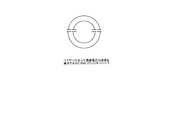
図1は、7個のコイルを含む簡易な構造を示す図である。すべてのコイルは、同一であり、かつ、必要に応じて(たとえば、低周波MITのために)、いくつかの薄層を有していてもよい。説明を簡単にするため、環状巻線のコイルが示され、かつ、外側巻線から内側巻線への交番は、この図から除外されている。コイルの各中心点は、破線の三角形で示される等辺の格子に配置されているが、これらは、もちろん、正方形の格子などの様々な他のパターンに配置されていてもよい。これらのコイル間の距離は、隣接コイルが駆動されている間に、電圧なしでコイルが誘導されるという必要条件によって決定される。 FIG. 1 is a diagram showing a simple structure including seven coils. All coils are identical and may have several thin layers as needed (eg, for low frequency MIT). For simplicity of explanation, an annular winding coil is shown and the alternating from the outer winding to the inner winding is omitted from this figure. The center points of the coils are arranged in an equilateral lattice indicated by a broken triangle, but these may of course be arranged in various other patterns such as a square lattice. The distance between these coils is determined by the requirement that the coils be induced without voltage while the adjacent coils are being driven.
換言すれば、この距離は、相互に誘導的に非結合な隣接コイルとなるように選択される。図1の構成の場合、たとえばコイル1は、コイル2、コイル3およびコイル4に対して非結合であるが、コイル4は、すべての他のコイルから誘導的に非結合とされる。実施例では、この必要とされる位置は、1個のコイルが他のコイルに関連して移動するときの、他のコイルに電圧供給する間に、1個のコイルの誘導電圧を測定することによって決定される。 In other words, this distance is selected to be adjacent coils that are inductively uncoupled from each other. In the case of the configuration shown in FIG. 1, for example, the coil 1 is not coupled to the coil 2, the coil 3, and the coil 4, but the coil 4 is inductively uncoupled from all other coils. In an embodiment, this required position is to measure the induced voltage of one coil as it is energized to another coil as it moves relative to the other coil. Determined by.
図1の構造の結合行列(またはK−行列)は、方程式(1)に示される。
Ldは、自己インダクタンスの行列である。多数のゼロ成分が、K−行列に存在していることが示されるであろう。このシステムの全インピーダンス行列は、方程式(2)によって与えられる。
コイルアレイの近くに組織が位置しない場合には、Rdは、コイルの自己抵抗を含む対角行列となる。このように、成分から成分への抵抗結合は、無視することができる。低周波の場合、容量結合も無視することができ、方程式(3)のインピーダンス行列が導出される。
Z=jωL+Rd (3)If no tissue is located near the coil array, Rd is a diagonal matrix containing the coil's self resistance. Thus, resistive coupling from component to component can be ignored. For low frequencies, capacitive coupling can also be ignored and the impedance matrix of equation (3) is derived.
Z = jωL + Rd (3)
図2は、完全に平らな32チャネル・システムの場合のコイル配置を示す。コイルが搭載される位置で、コイルの横方向への拡張が、コイルの搭載されているプリント基板の曲げ半径と比較して僅かである場合、安定したままの非結合となるであろう。これにより、ボディ、たとえば衣服の近くに、コイルアレイを配置することが可能になる。 FIG. 2 shows the coil arrangement for a completely flat 32-channel system. If the coil is mounted at a location where the lateral expansion of the coil is small compared to the bend radius of the printed circuit board on which the coil is mounted, it will remain uncoupled. This makes it possible to place the coil array near the body, for example clothing.
高周波の場合、および、人体までのセンサの距離が短い場合には、コイル間の容量結合、および、組織に対するコイルの容量結合は、できる限り、低く保持すべきである。したがって、ブリッジキャパシタは、巻線と外側電場との間の電圧増加を回避するために、すなわち、誘導リアクタンスを補償するために、図3に示すように、間隔をおいて置かれる。すべてのキャパシタは、同じ値となり、かつ、コイルの純粋な真の入力インピーダンス(自己共振構成)を導出するであろう。周波数が高ければ高いほど、より多くのキャパシタが用いられるはずである。 In the case of high frequency and when the distance of the sensor to the human body is short, the capacitive coupling between the coils and the capacitive coupling of the coil to the tissue should be kept as low as possible. Thus, the bridge capacitors are spaced apart as shown in FIG. 3 to avoid voltage increase between the winding and the outer electric field, ie to compensate for inductive reactance. All capacitors will have the same value and will derive the pure true input impedance (self-resonant configuration) of the coil. The higher the frequency, the more capacitors should be used.
図4は、コイルが重畳されて一対に配置される2層コイル・システムの原理を例示する。2個のコイル設計についての基本的な考えは、上部コイルによって作成される場B1が、上部コイルから特定の間隔dで設置される付加的な下部コイルによって作成される場B2によって補償される。図5は、2個の逆平行に接続されたコイルから構成される、コイルの等価回路図である。そのコイルは、若干の距離を補償し、したがって、全体の感度のうちの若干の減少を犠牲にして、周囲の電磁放射をあまり感知できないセンサを形成するであろう。この配置は、さらに、全体のMIT手順に優れたアレイの「次々結合」(すなわち、1個ではない次のコイルへの結合)の減少を補助する。FIG. 4 illustrates the principle of a two-layer coil system where coils are superimposed and placed in pairs. The basic idea for the two coil design is that the field B1 created by the upper coil is compensated by the field B2 created by an additional lower coil installed at a certain distance d from the upper coil. The FIG. 5 is an equivalent circuit diagram of a coil composed of two antiparallel connected coils. The coil will compensate for some distance and thus form a sensor that is less sensitive to ambient electromagnetic radiation at the expense of some reduction in overall sensitivity. This arrangement further helps to reduce the “sequential coupling” (ie coupling to the next coil that is not one) superior to the overall MIT procedure.
センサアレイが非常に薄くて作成できると、磁場勾配計のような予備のセンシングデバイスが不要となるので、センサアレイを、容易に移動可能なセンサ・パッドに組み込むことができ、かつ、例えば患者のベッド、または、衣類の部材に「現場で」用いることができる。加えて、もちろん、センサアレイは、患者の本体に近接して配置される、付加的な励起/センシングコイルを提供するために、MRI装置のような器具と併用して用いることもできる。 If the sensor array can be made very thin, a spare sensing device such as a magnetic field gradient meter is not required, so the sensor array can be incorporated into an easily movable sensor pad and, for example, the patient's It can be used "in the field" for a bed or garment member. In addition, of course, the sensor array can also be used in conjunction with an instrument such as an MRI apparatus to provide an additional excitation / sensing coil that is placed in close proximity to the patient's body.
Claims (8)
Translated fromJapanese前記第1の層における各コイルは、前記第2の層における個別のコイルと一対で配置され、前記コイルの対が、逆平行に接続され、及び相互の場を補償し、かつ、これにより外部の結合効果を減少させるように離れて配置される、磁気インダクタンス断層撮影装置用のセンサコイルアレイ又はドライバコイルアレイ。Including at leasttwo thin coils,each layer including a plurality of thin coils, the centers of which are arranged on a fixed grid, suitable to offset inductive adjacent coupling between adjacent coils ina layer Superimposed ata distance,
Each coil in the first layer is arranged in a pair with an individual coil in the second layer, the pairs of coils are connected in antiparallel and compensate for the mutual field and thereby external A sensorcoil array or a driver coil array for a magnetic inductance tomography apparatus, which is spaced apart to reduce the coupling effect of
Applications Claiming Priority (3)
| Application Number | Priority Date | Filing Date | Title |
|---|---|---|---|
| EP06118774 | 2006-08-11 | ||
| EP06118774.6 | 2006-08-11 | ||
| PCT/IB2007/053107WO2008018018A2 (en) | 2006-08-11 | 2007-08-07 | Sensor coil array for magnetic inductance tomography with reduced mutual coil coupling |
Publications (2)
| Publication Number | Publication Date |
|---|---|
| JP2010500090A JP2010500090A (en) | 2010-01-07 |
| JP5474542B2true JP5474542B2 (en) | 2014-04-16 |
Family
ID=39033356
Family Applications (1)
| Application Number | Title | Priority Date | Filing Date |
|---|---|---|---|
| JP2009523417AExpired - Fee RelatedJP5474542B2 (en) | 2006-08-11 | 2007-08-07 | Sensor array for magnetic inductance tomography |
Country Status (5)
| Country | Link |
|---|---|
| US (1) | US7923995B2 (en) |
| EP (1) | EP2052274A2 (en) |
| JP (1) | JP5474542B2 (en) |
| CN (1) | CN101501521B (en) |
| WO (1) | WO2008018018A2 (en) |
Families Citing this family (18)
| Publication number | Priority date | Publication date | Assignee | Title |
|---|---|---|---|---|
| FR2881826A1 (en)* | 2005-02-04 | 2006-08-11 | Commissariat Energie Atomique | Transmission and reception printed circuit coils assembly producing method, involves receiving complex amplitude signal and selecting distance between axes of transmission coil and reception coil so as to maximize specific ratio |
| GB2462243A (en)* | 2008-05-28 | 2010-02-03 | Ugcs | Magnetic induction tomography with two reference signals |
| WO2010097726A1 (en)* | 2009-02-27 | 2010-09-02 | Koninklijke Philips Electronics N.V. | A magnetic induction tomography system |
| CN103442634A (en)* | 2011-02-03 | 2013-12-11 | 皇家飞利浦电子股份有限公司 | Planar Coil Arrangement for Magnetic Inductive Impedance Measurement Device |
| US9488705B2 (en) | 2011-07-20 | 2016-11-08 | Koninklijke Philips N.V. | Wireless local transmit coils and array with controllable load |
| DE102012217760A1 (en)* | 2012-09-28 | 2014-04-03 | Siemens Ag | Decoupling of split-ring resonators in magnetic resonance imaging |
| US9496746B2 (en) | 2013-05-15 | 2016-11-15 | The Regents Of The University Of Michigan | Wireless power transmission for battery charging |
| CN103730245B (en)* | 2014-01-07 | 2016-06-29 | 东南大学 | A kind of for the laminated inductance in passive and wireless multiparameter microsensor |
| US9207197B2 (en) | 2014-02-27 | 2015-12-08 | Kimberly-Clark Worldwide, Inc. | Coil for magnetic induction to tomography imaging |
| US9442088B2 (en) | 2014-02-27 | 2016-09-13 | Kimberly-Clark Worldwide, Inc. | Single coil magnetic induction tomographic imaging |
| US9320451B2 (en) | 2014-02-27 | 2016-04-26 | Kimberly-Clark Worldwide, Inc. | Methods for assessing health conditions using single coil magnetic induction tomography imaging |
| US10349864B2 (en)* | 2015-04-17 | 2019-07-16 | Elwha Llc | Methods and system for performing magnetic induction tomography |
| CN107728087B (en)* | 2016-08-10 | 2020-12-22 | 西门子(深圳)磁共振有限公司 | Bendable body array coil |
| WO2018215384A1 (en)* | 2017-05-22 | 2018-11-29 | Smith & Nephew Plc | Systems and methods for performing magnetic induction tomography |
| JP7396787B2 (en)* | 2018-04-04 | 2023-12-12 | スミダコーポレーション株式会社 | Microcurrent detection device and microcurrent detection method |
| JP2020085668A (en) | 2018-11-27 | 2020-06-04 | エイブリック株式会社 | Magnetic sensor |
| CN110412487B (en)* | 2019-07-31 | 2021-04-20 | 电子科技大学 | A fabric-type flexible composite sensor and its manufacturing method |
| CN113433495B (en)* | 2021-06-25 | 2022-08-05 | 中国科学院自动化研究所 | Open type magnetic particle three-dimensional imaging system and method based on array type receiving coil |
Family Cites Families (12)
| Publication number | Priority date | Publication date | Assignee | Title |
|---|---|---|---|---|
| JPH0693677B2 (en)* | 1987-01-12 | 1994-11-16 | 富士通株式会社 | Identification timing control circuit |
| WO1989005115A1 (en) | 1987-12-07 | 1989-06-15 | General Electric Company | Nuclear magnetic resonance (nmr) imaging with multiple surface coils |
| US5144236A (en)* | 1990-08-17 | 1992-09-01 | Strenk Scientific Consultants, Inc. | Method and apparatus for r.f. tomography |
| US5825164A (en)* | 1995-12-21 | 1998-10-20 | Adb-Alnaco, Inc. | Inductance controller with load regulator |
| CN1140772C (en)* | 2000-04-19 | 2004-03-03 | 浙江大学 | Imaging electromagnetic flowmeter |
| US6768921B2 (en) | 2000-12-28 | 2004-07-27 | Z-Tech (Canada) Inc. | Electrical impedance method and apparatus for detecting and diagnosing diseases |
| WO2004026136A1 (en) | 2002-09-17 | 2004-04-01 | Beth Israel Deaconess Medical Center, Inc. | Radio frequency impedance mapping |
| JP4212331B2 (en)* | 2002-10-24 | 2009-01-21 | 株式会社日立メディコ | Magnetic resonance imaging apparatus and superconducting magnet apparatus |
| US20050073309A1 (en) | 2003-10-01 | 2005-04-07 | Williams Neil R. | Magnetic resonance coil modules |
| JP2005294537A (en)* | 2004-03-31 | 2005-10-20 | Takenaka Komuten Co Ltd | Panel-type coil, uniform magnetic field generator, gradient magnetic field generator and magnetic field canceling device |
| US7282915B2 (en) | 2004-05-14 | 2007-10-16 | General Electric Company | Multi-turn element RF coil array for multiple channel MRI |
| WO2005124380A2 (en) | 2004-06-17 | 2005-12-29 | Koninklijke Philips Electronics, N.V. | Flexible and wearable radio frequency coil garments for magnetic resonance imaging |
- 2007
- 2007-08-07JPJP2009523417Apatent/JP5474542B2/ennot_activeExpired - Fee Related
- 2007-08-07WOPCT/IB2007/053107patent/WO2008018018A2/enactiveApplication Filing
- 2007-08-07EPEP07825993Apatent/EP2052274A2/ennot_activeWithdrawn
- 2007-08-07USUS12/376,582patent/US7923995B2/ennot_activeExpired - Fee Related
- 2007-08-07CNCN200780029862.5Apatent/CN101501521B/ennot_activeExpired - Fee Related
Also Published As
| Publication number | Publication date |
|---|---|
| EP2052274A2 (en) | 2009-04-29 |
| US20100181998A1 (en) | 2010-07-22 |
| US7923995B2 (en) | 2011-04-12 |
| CN101501521A (en) | 2009-08-05 |
| CN101501521B (en) | 2012-12-12 |
| WO2008018018A2 (en) | 2008-02-14 |
| JP2010500090A (en) | 2010-01-07 |
| WO2008018018A3 (en) | 2008-06-05 |
Similar Documents
| Publication | Publication Date | Title |
|---|---|---|
| JP5474542B2 (en) | Sensor array for magnetic inductance tomography | |
| JP7284739B2 (en) | Magnetic sensor and inspection device | |
| US8808190B2 (en) | Planar coil arrangement for a magnetic induction impedance measurement apparatus | |
| US20110172512A1 (en) | Method and system for magnetic induction tomography | |
| US20080218180A1 (en) | Apparatus, a System and a Method for Enabling an Impedance Measurement | |
| CA2442614A1 (en) | Simplified water-bag technique for magnetic susceptibility measurements on the human body and other specimens | |
| JP7319683B2 (en) | Magnetic sensor and diagnostic equipment | |
| CN103492895A (en) | Magnetic detection device | |
| WO2006111877A1 (en) | Method and apparatus for inductively measuring the bio-impedance of a user’s body | |
| US7196514B2 (en) | Multi-conductive ferromagnetic core, variable permeability field sensor and method | |
| JP2010512916A (en) | Apparatus and method for influencing and / or detecting magnetic particles in a working region | |
| JP5486313B2 (en) | Apparatus and method for influencing and / or detecting magnetic particles in a working region | |
| JP5379695B2 (en) | Method and arrangement for positioning magnetic markers in the area of action | |
| CN114720920B (en) | Magnetic sensor and inspection device | |
| US6853186B2 (en) | Variable permeability magnetic field sensor and method | |
| CN111770726B (en) | Design, manufacture of an MRI tracking device and method of use for an MRI guided robot system | |
| RU2678794C2 (en) | Magnetic resonance safe low cost probe for temperature measurement | |
| JP7414703B2 (en) | Magnetic sensor and inspection equipment | |
| JP7426956B2 (en) | Magnetic sensor and inspection equipment | |
| JP5139822B2 (en) | Magnetic field probe | |
| JP2022114102A (en) | Magnetic sensor and inspection device | |
| JP2024006692A (en) | Sensors and inspection equipment | |
| JP2022108343A (en) | Magnetic sensor and inspection device |
Legal Events
| Date | Code | Title | Description |
|---|---|---|---|
| A621 | Written request for application examination | Free format text:JAPANESE INTERMEDIATE CODE: A621 Effective date:20100805 | |
| A131 | Notification of reasons for refusal | Free format text:JAPANESE INTERMEDIATE CODE: A131 Effective date:20130509 | |
| A601 | Written request for extension of time | Free format text:JAPANESE INTERMEDIATE CODE: A601 Effective date:20130809 | |
| A602 | Written permission of extension of time | Free format text:JAPANESE INTERMEDIATE CODE: A602 Effective date:20130816 | |
| A521 | Request for written amendment filed | Free format text:JAPANESE INTERMEDIATE CODE: A523 Effective date:20131001 | |
| TRDD | Decision of grant or rejection written | ||
| A01 | Written decision to grant a patent or to grant a registration (utility model) | Free format text:JAPANESE INTERMEDIATE CODE: A01 Effective date:20140107 | |
| A61 | First payment of annual fees (during grant procedure) | Free format text:JAPANESE INTERMEDIATE CODE: A61 Effective date:20140205 | |
| R150 | Certificate of patent or registration of utility model | Free format text:JAPANESE INTERMEDIATE CODE: R150 | |
| R250 | Receipt of annual fees | Free format text:JAPANESE INTERMEDIATE CODE: R250 | |
| LAPS | Cancellation because of no payment of annual fees |