JP5474463B2 - Non-contact power receiving apparatus and electric vehicle including the same - Google Patents
Non-contact power receiving apparatus and electric vehicle including the sameDownload PDFInfo
- Publication number
- JP5474463B2 JP5474463B2JP2009214211AJP2009214211AJP5474463B2JP 5474463 B2JP5474463 B2JP 5474463B2JP 2009214211 AJP2009214211 AJP 2009214211AJP 2009214211 AJP2009214211 AJP 2009214211AJP 5474463 B2JP5474463 B2JP 5474463B2
- Authority
- JP
- Japan
- Prior art keywords
- power
- resonator
- relay
- voltage
- power receiving
- Prior art date
- Legal status (The legal status is an assumption and is not a legal conclusion. Google has not performed a legal analysis and makes no representation as to the accuracy of the status listed.)
- Expired - Fee Related
Links
Images


Classifications
- Y—GENERAL TAGGING OF NEW TECHNOLOGICAL DEVELOPMENTS; GENERAL TAGGING OF CROSS-SECTIONAL TECHNOLOGIES SPANNING OVER SEVERAL SECTIONS OF THE IPC; TECHNICAL SUBJECTS COVERED BY FORMER USPC CROSS-REFERENCE ART COLLECTIONS [XRACs] AND DIGESTS
- Y02—TECHNOLOGIES OR APPLICATIONS FOR MITIGATION OR ADAPTATION AGAINST CLIMATE CHANGE
- Y02T—CLIMATE CHANGE MITIGATION TECHNOLOGIES RELATED TO TRANSPORTATION
- Y02T10/00—Road transport of goods or passengers
- Y02T10/60—Other road transportation technologies with climate change mitigation effect
- Y02T10/72—Electric energy management in electromobility
Landscapes
- Protection Of Static Devices (AREA)
- Current-Collector Devices For Electrically Propelled Vehicles (AREA)
- Electric Propulsion And Braking For Vehicles (AREA)
Description
Translated fromJapaneseこの発明は、非接触受電装置およびそれを備える電動車両に関し、特に、電源から電力を受けて電磁場を発生する送電用共鳴器から前記電磁場を介して非接触で受電する非接触受電装置およびそれを備える電動車両に関する。 The present invention relates to a non-contact power receiving device and an electric vehicle including the same, and more particularly to a non-contact power receiving device that receives power from a power transmission resonator that receives power from a power source and generates an electromagnetic field in a non-contact manner via the electromagnetic field. The present invention relates to an electric vehicle provided.
環境に配慮した車両として、電気自動車やハイブリッド自動車などの電動車両が大きく注目されている。これらの車両は、走行駆動力を発生する電動機と、その電動機に供給される電力を蓄える再充電可能な蓄電装置とを搭載する。なお、ハイブリッド自動車は、電動機とともに内燃機関をさらに動力源として搭載した自動車や、車両駆動用の直流電源として蓄電装置とともに燃料電池をさらに搭載した自動車である。 Electric vehicles such as electric vehicles and hybrid vehicles have attracted a great deal of attention as environmentally friendly vehicles. These vehicles are equipped with an electric motor that generates driving force and a rechargeable power storage device that stores electric power supplied to the electric motor. The hybrid vehicle is a vehicle in which an internal combustion engine is further mounted as a power source together with an electric motor, or a fuel cell is further mounted as a direct current power source for driving the vehicle together with a power storage device.
ハイブリッド自動車においても、電気自動車と同様に、車両外部の電源から車載の蓄電装置を充電可能な車両が知られている。たとえば、家屋に設けられた電源コンセントと車両に設けられた充電口とを充電ケーブルで接続することにより、一般家庭の電源から蓄電装置を充電可能ないわゆる「プラグイン・ハイブリッド自動車」が知られている。 In hybrid vehicles, as in the case of electric vehicles, vehicles that can charge an in-vehicle power storage device from a power source outside the vehicle are known. For example, a so-called “plug-in hybrid vehicle” is known that can charge a power storage device from a general household power source by connecting a power outlet provided in a house to a charging port provided in the vehicle with a charging cable. Yes.
一方、送電方法として、電源コードや送電ケーブルを用いないワイヤレス送電が近年注目されている。このワイヤレス送電技術としては、有力なものとして、電磁誘導を用いた送電、マイクロ波を用いた送電、および共鳴法による送電の3つの技術が知られている。 On the other hand, as a power transmission method, wireless power transmission that does not use a power cord or a power transmission cable has recently attracted attention. As this wireless power transmission technology, three technologies known as power transmission using electromagnetic induction, power transmission using microwaves, and power transmission using a resonance method are known.
このうち、共鳴法は、一対の共鳴器(たとえば一対の自己共振コイル)を電磁場(近接場)において共鳴させ、電磁場を介して送電する非接触の送電技術であり、数kWの大電力を比較的長距離(たとえば数m)送電することも可能である(たとえば、特許文献1参照)。 Among them, the resonance method is a non-contact power transmission technique in which a pair of resonators (for example, a pair of self-resonant coils) are resonated in an electromagnetic field (near field) and transmitted through the electromagnetic field. It is also possible to transmit power over a long distance (for example, several meters) (see, for example, Patent Document 1).
車両外部の電源から車両への送電に上記の共鳴法を用いる場合、受電電力に基づいて給電設備と車両との距離を算出し、その算出された距離情報に基づいて、給電設備に対する車両の位置合わせを行なうことが可能である。たとえば、給電設備のインピーダンスにマッチングさせた抵抗を、受電電力を電気負荷へ供給する電力線対間にリレーによって電気的に接続し、給電設備からテスト送電を行なったときに上記抵抗に生じる電圧を測定することによって、車両の受電ユニットと給電設備の送電ユニットとの間の距離を推定することが可能である。 When the above resonance method is used for power transmission from a power source outside the vehicle to the vehicle, the distance between the power supply facility and the vehicle is calculated based on the received power, and the position of the vehicle relative to the power supply facility is calculated based on the calculated distance information. It is possible to match. For example, a resistor matched to the impedance of the power supply equipment is electrically connected by a relay between the power line pair that supplies the received power to the electric load, and the voltage generated in the resistance is measured when test transmission is performed from the power supply equipment. By doing so, it is possible to estimate the distance between the power receiving unit of the vehicle and the power transmission unit of the power supply facility.
そして、上記の抵抗を用いた車両の位置合わせ終了後は、上記リレーによって電力線対間から抵抗を電気的に切離す必要がある。仮にこのリレーが溶着すると、受電電力を電気負荷へ適切に供給できなくなるので、上記リレーの溶着有無をチェックする必要がある。 And after completion of vehicle positioning using the above-mentioned resistance, it is necessary to electrically disconnect the resistance from between the power line pair by the relay. If this relay is welded, the received power cannot be properly supplied to the electric load, so it is necessary to check whether the relay is welded.
それゆえに、この発明の目的は、給電設備と車両との位置合わせ時に用いられる検出用抵抗の電気的な接続/切離しを行なうリレーの溶着チェックを実施可能な非接触受電装置およびそれを備える電動車両を提供することである。 SUMMARY OF THE INVENTION Therefore, an object of the present invention is to provide a non-contact power receiving apparatus capable of performing a welding check of a relay for electrically connecting / disconnecting a detection resistor used when positioning a power supply facility and a vehicle, and an electric vehicle including the same Is to provide.
この発明によれば、非接触受電装置は、電源から電力を受けて電磁場を発生する送電用共鳴器から電磁場を介して非接触で受電する非接触受電装置であって、受電用共鳴器と、電気負荷と、第1の抵抗およびリレーと、電圧センサと、判定部を備える。受電用共鳴器は、送電用共鳴器と電磁場を介して共鳴することにより送電用共鳴器から受電するように構成される。電気負荷は、受電用共鳴器によって受電された電力の供給を受ける。第1の抵抗およびリレーは、受電用共鳴器と電気負荷との間に配設される電力線対間に直列に接続される。電圧センサは、電力線対間の電圧を検出する。ここで、リレーが非導通状態のとき、当該非接触受電装置の耐電圧を受電電圧が超えないように送電用共鳴器から受電用共鳴器へ所定の電力が送出される。そして、判定部は、リレーが非導通状態に制御され、かつ、送電用共鳴器から受電用共鳴器へ所定の電力が送出されているとき、電圧センサの検出値に基づいてリレーの溶着有無を判定する。 According to the present invention, the non-contact power receiving device is a non-contact power receiving device that receives power from a power transmission resonator that receives power from a power source and generates an electromagnetic field in a non-contact manner via the electromagnetic field, the power receiving resonator; An electrical load, a first resistor and a relay, a voltage sensor, and a determination unit are provided. The power receiving resonator is configured to receive power from the power transmitting resonator by resonating with the power transmitting resonator via an electromagnetic field. The electric load is supplied with the electric power received by the power receiving resonator. The first resistor and the relay are connected in series between a pair of power lines disposed between the power receiving resonator and the electric load. The voltage sensor detects a voltage between the power line pair. Here, when the relay is in a non-conductive state, predetermined power is sent from the power transmission resonator to the power reception resonator so that the power reception voltage does not exceed the withstand voltage of the contactless power reception device. The determination unit determines whether or not the relay is welded based on the detection value of the voltage sensor when the relay is controlled to be in a non-conductive state and predetermined power is being transmitted from the power transmission resonator to the power reception resonator. judge.
好ましくは、非接触受電装置は、第2の抵抗をさらに備える。第2の抵抗は、第1の抵抗の抵抗値よりも大きく、かつ、所定の電力の受電時に受電電圧が耐電圧を超えないように設計された抵抗値を有し、直列に接続された第1の抵抗およびリレーに並列に接続される。 Preferably, the non-contact power receiving apparatus further includes a second resistor. The second resistor has a resistance value that is greater than the resistance value of the first resistor and is designed so that the received voltage does not exceed the withstand voltage when receiving a predetermined power, and the second resistor is connected in series. 1 resistor and relay connected in parallel.
また、好ましくは、非接触受電装置は、制御部をさらに備える。制御部は、リレーが非導通状態に制御され、かつ、送電用共鳴器から受電用共鳴器へ所定の電力が送出されているとき、電気負荷の入力インピーダンスが第1の抵抗の抵抗値よりも大きく、かつ、受電電圧が耐電圧を超えないように電気負荷を制御する。 Preferably, the non-contact power receiving apparatus further includes a control unit. The control unit is configured such that when the relay is controlled to be in a non-conductive state and predetermined power is being transmitted from the power transmitting resonator to the power receiving resonator, the input impedance of the electric load is greater than the resistance value of the first resistor. The electric load is controlled so as to be large and the received voltage does not exceed the withstand voltage.
さらに好ましくは、非接触受電装置は、蓄電装置をさらに備える。蓄電装置は、受電用共鳴器によって受電される電力を蓄える。電気負荷は、受電用共鳴器によって受電された電力を受けて蓄電装置を充電するように構成されたコンバータを含む。そして、制御部は、リレーが非導通状態に制御され、かつ、送電用共鳴器から受電用共鳴器へ所定の電力が送出されているとき、コンバータの入力インピーダンスが第1の抵抗の抵抗値よりも大きく、かつ、受電電圧が耐電圧を超えないようにコンバータを制御する。 More preferably, the non-contact power receiving device further includes a power storage device. The power storage device stores electric power received by the power receiving resonator. The electrical load includes a converter configured to receive the power received by the power receiving resonator and charge the power storage device. The control unit is configured such that when the relay is controlled to be in a non-conductive state and predetermined power is being transmitted from the power transmitting resonator to the power receiving resonator, the input impedance of the converter is greater than the resistance value of the first resistor. And the converter is controlled so that the received voltage does not exceed the withstand voltage.
好ましくは、非接触受電装置は、通信部をさらに備える。通信部は、送電用共鳴器から受電用共鳴器への所定の電力の送出を指示する指令を、送電用共鳴器を含む給電設備へ送信する。 Preferably, the non-contact power receiving apparatus further includes a communication unit. The communication unit transmits a command instructing transmission of predetermined power from the power transmission resonator to the power reception resonator to the power supply facility including the power transmission resonator.
また、この発明によれば、電動車両は、上述したいずれかの非接触受電装置と、非接触受電装置によって受電された電力を用いて走行トルクを発生する電動機とを備える。 In addition, according to the present invention, an electric vehicle includes any one of the non-contact power receiving devices described above and an electric motor that generates a running torque using the electric power received by the non-contact power receiving device.
この発明においては、受電用共鳴器と電気負荷との間に配設される電力線対間に第1の抵抗およびリレーが直列に接続され、リレーが非導通状態のとき、非接触受電装置の耐電圧を受電電圧が超えないように送電用共鳴器から受電用共鳴器へ所定の電力が送出される。そして、リレーが非導通状態に制御され、かつ、送電用共鳴器から受電用共鳴器へ所定の電力が送出されているとき、電圧センサの検出値に基づいてリレーの溶着有無が判定される。たとえば、電圧センサの検出値が所定値と比較され、電圧センサの検出値が所定値よりも大きいときリレーは正常と判定され、電圧センサの検出値が所定値以下のときリレーが溶着していると判定される。 In the present invention, when the first resistor and the relay are connected in series between the power line pair disposed between the power receiving resonator and the electric load, and the relay is in a non-conductive state, Predetermined power is sent from the power transmitting resonator to the power receiving resonator so that the received voltage does not exceed the voltage. When the relay is controlled to be in a non-conducting state and predetermined power is being sent from the power transmission resonator to the power reception resonator, whether or not the relay is welded is determined based on the detection value of the voltage sensor. For example, the detection value of the voltage sensor is compared with a predetermined value. When the detection value of the voltage sensor is larger than the predetermined value, the relay is determined to be normal, and when the detection value of the voltage sensor is equal to or less than the predetermined value, the relay is welded. It is determined.
したがって、この発明によれば、上記第1の抵抗の電気的な接続/切離しを行なうリレーの溶着チェックを実施可能な非接触受電装置および電動車両を提供することができる。 Therefore, according to the present invention, it is possible to provide a non-contact power receiving apparatus and an electric vehicle capable of performing a welding check of a relay that electrically connects / disconnects the first resistor.
以下、本発明の実施の形態について、図面を参照しながら詳細に説明する。なお、図中同一または相当部分には同一符号を付してその説明は繰返さない。 Hereinafter, embodiments of the present invention will be described in detail with reference to the drawings. In the drawings, the same or corresponding parts are denoted by the same reference numerals and description thereof will not be repeated.
[実施の形態1]
図1は、この発明の実施の形態1による非接触受電装置が適用される車両給電システムの全体構成図である。図1を参照して、車両給電システム10は、車両100と、給電設備200とを備える。[Embodiment 1]
1 is an overall configuration diagram of a vehicle power feeding system to which a non-contact power receiving device according to Embodiment 1 of the present invention is applied. Referring to FIG. 1, vehicle
車両100は、受電ユニット110と、カメラ120と、通信ユニット130とを含む。受電ユニット110は、車体底面に設置され、給電設備200の送電ユニット220から送出される電力を非接触で受電するように構成される。詳しくは、受電ユニット110は、後に説明する自己共振コイルを含み、給電設備200の送電ユニット220に含まれる自己共振コイルと電磁場を介して共鳴することにより送電ユニット220から非接触で受電する。
カメラ120は、受電ユニット110と送電ユニット220との位置関係を検知するために設けられ、たとえば車両後方を撮影可能に車体に取付けられる。通信ユニット130は、車両100と給電設備200との間で通信を行なうための通信インターフェースである。 The
給電設備200は、高周波電源装置210と、送電ユニット220と、発光部230と、通信ユニット240とを含む。高周波電源装置210は、たとえば系統電源から供給される商用交流電力を高周波の電力に変換して送電ユニット220へ出力する。なお、高周波電源装置210が生成する高周波電力の周波数は、たとえば1MHz〜数十MHzである。 The
送電ユニット220は、駐車場の床面に固設され、高周波電源装置210から供給される高周波電力を車両100の受電ユニット110へ非接触で送出するように構成される。詳しくは、送電ユニット220は、自己共振コイルを含み、車両100の受電ユニット110に含まれる自己共振コイルと電磁場を介して共鳴することにより受電ユニット110へ非接触で送電する。 The
発光部230は、送電ユニット220上に複数設けられ、送電ユニット220の位置を示すために設けられる。発光部230は、たとえば発光ダイオードなどを含む。通信ユニット240は、給電設備200と車両100との間で通信を行なうための通信インターフェースである。 A plurality of light emitting
この車両給電システム10においては、給電設備200の送電ユニット220から高周波の電力が送出され、車両100の受電ユニット110に含まれる自己共振コイルと送電ユニット220に含まれる自己共振コイルとが電磁場を介して共鳴することにより、給電設備200から車両100へ給電される。 In the vehicle
ここで、給電設備200から車両100への給電に際し、車両100を給電設備200へ誘導して車両100の受電ユニット110と給電設備200の送電ユニット220との位置合わせが行なわれる。 Here, when power is supplied from the
位置合わせは、まず、第1段階においては、カメラ120によって撮影される画像に基づいて車両100の受電ユニット110と給電設備200の送電ユニット220との位置関係が検知され、その検知結果に基づいて送電ユニット220へ車両を誘導するように車両が制御される。より詳しくは、送電ユニット220上に設けられた複数の発光部230がカメラ120によって撮影され、複数の発光部230の位置および向きが画像認識される。そして、その画像認識の結果に基づいて送電ユニット220と車両との位置および向きが認識され、その認識結果に基づいて送電ユニット220へ車両が誘導される。 First, in the first stage, the positional relationship between the
ここで、受電ユニット110および送電ユニット220の対向面積は、車体底面の面積よりも小さいところ、送電ユニット220が車体下部に入り込むことによってカメラ120により送電ユニット220を撮影できなくなると、第1段階から第2段階に切替わる。この第2段階においては、送電ユニット220から受電ユニット110への給電が行なわれ、その給電状況に基づいて送電ユニット220と受電ユニット110との距離が検知される。そして、その距離情報に基づいて、送電ユニット220と受電ユニット110との位置合わせを行なうように車両が制御される。 Here, the facing area of the
なお、上記の第2段階時に送電ユニット220から送出される電力の大きさは、送電ユニット220と受電ユニット110との位置合わせの完了後に送電ユニット220から受電ユニット110へ供給される充電電力よりも小さく設定される。上記第2段階時に送電ユニット220から電力を送出するのは、送電ユニット220と受電ユニット110との間の距離を検知するためであり、本格的な給電を行なう際の大電力は不要だからである。 Note that the magnitude of the electric power transmitted from the
次に、この車両給電システム10に用いられる非接触給電方法について説明する。この実施の形態による車両給電システム10では、共鳴法を用いて給電設備200から車両100への給電が行なわれる。 Next, a non-contact power feeding method used for the vehicle
図2は、共鳴法による送電の原理を説明するための図である。図2を参照して、この共鳴法では、2つの音叉が共鳴するのと同様に、同じ固有振動数を有する2つのLC共振コイルが電磁場(近接場)において共鳴することによって、一方のコイルから他方のコイルへ電磁場を介して電力が伝送される。 FIG. 2 is a diagram for explaining the principle of power transmission by the resonance method. Referring to FIG. 2, in this resonance method, in the same way as two tuning forks resonate, two LC resonance coils having the same natural frequency resonate in an electromagnetic field (near field), and thereby, from one coil. Electric power is transmitted to the other coil via an electromagnetic field.
具体的には、高周波電源310に一次コイル320を接続し、電磁誘導により一次コイル320と磁気的に結合される一次自己共振コイル330へ1M〜数十MHzの高周波電力を給電する。一次自己共振コイル330は、コイル自身のインダクタンスと浮遊容量とによるLC共振器であり、一次自己共振コイル330と同じ共振周波数を有する二次自己共振コイル340と電磁場(近接場)を介して共鳴する。そうすると、一次自己共振コイル330から二次自己共振コイル340へ電磁場を介してエネルギー(電力)が移動する。二次自己共振コイル340へ移動したエネルギー(電力)は、電磁誘導により二次自己共振コイル340と磁気的に結合される二次コイル350によって取出され、負荷360へ供給される。なお、共鳴法による送電は、一次自己共振コイル330と二次自己共振コイル340との共鳴強度を示すQ値がたとえば100よりも大きいときに実現される。 Specifically, the
なお、図1との対応関係については、二次自己共振コイル340および二次コイル350が図1の受電ユニット110に対応し、一次コイル320および一次自己共振コイル330が図1の送電ユニット220に対応する。 1, the secondary self-
図3は、電流源(磁流源)からの距離と電磁界の強度との関係を示した図である。図3を参照して、電磁界は3つの成分を含む。曲線k1は、波源からの距離に反比例した成分であり、「輻射電磁界」と称される。曲線k2は、波源からの距離の2乗に反比例した成分であり、「誘導電磁界」と称される。また、曲線k3は、波源からの距離の3乗に反比例した成分であり、「静電磁界」と称される。 FIG. 3 is a diagram showing the relationship between the distance from the current source (magnetic current source) and the intensity of the electromagnetic field. Referring to FIG. 3, the electromagnetic field includes three components. The curve k1 is a component that is inversely proportional to the distance from the wave source, and is referred to as a “radiated electromagnetic field”. A curve k2 is a component inversely proportional to the square of the distance from the wave source, and is referred to as an “induction electromagnetic field”. The curve k3 is a component inversely proportional to the cube of the distance from the wave source, and is referred to as an “electrostatic magnetic field”.
この中でも波源からの距離とともに急激に電磁波の強度が減少する領域があるが、共鳴法では、この近接場(エバネッセント場)を利用してエネルギー(電力)の伝送が行なわれる。すなわち、近接場を利用して、同じ固有振動数を有する一対の共鳴器(たとえば一対のLC共振コイル)を共鳴させることにより、一方の共鳴器(一次自己共振コイル)から他方の共鳴器(二次自己共振コイル)へエネルギー(電力)を伝送する。この近接場は遠方にエネルギー(電力)を伝播しないので、遠方までエネルギーを伝播する「輻射電磁界」によりエネルギー(電力)を伝送する電磁波に比べて、共鳴法は、より少ないエネルギー損失で送電することができる。 Among these, there is a region where the intensity of the electromagnetic wave rapidly decreases with the distance from the wave source. In the resonance method, energy (electric power) is transmitted using this near field (evanescent field). That is, by using a near field to resonate a pair of resonators (for example, a pair of LC resonance coils) having the same natural frequency, one resonator (primary self-resonant coil) and the other resonator (two Energy (electric power) is transmitted to the next self-resonant coil. Since this near field does not propagate energy (electric power) far away, the resonance method transmits power with less energy loss than electromagnetic waves that transmit energy (electric power) by "radiation electromagnetic field" that propagates energy far away. be able to.
図4は、図1に示した車両100の詳細を示す構成図である。図4を参照して、車両100は、蓄電装置150と、システムメインリレーSMR1と、昇圧コンバータ162と、インバータ164,166と、モータジェネレータ172,174と、エンジン176と、動力分割装置177と、駆動輪178とを含む。また、車両100は、二次自己共振コイル112と、二次コイル114と、整流器140と、DC/DCコンバータ142と、システムメインリレーSMR2と、リレー144,148と、抵抗146と、電圧センサ190とをさらに含む。さらに、車両100は、制御装置180と、カメラ120と、通信ユニット130と、給電ボタン122とをさらに含む。 FIG. 4 is a configuration diagram showing details of the
この車両100は、エンジン176およびモータジェネレータ174を動力源として搭載する。エンジン176およびモータジェネレータ172,174は、遊星歯車から成る動力分割装置177に連結される。そして、車両100は、エンジン176およびモータジェネレータ174の少なくとも一方が発生する駆動力によって走行する。エンジン176が発生する動力は、動力分割装置177によって2経路に分割される。すなわち、一方は駆動輪178へ伝達される経路であり、もう一方はモータジェネレータ172へ伝達される経路である。 The
モータジェネレータ172は、交流回転電機であり、たとえばロータに永久磁石が埋設された三相交流同期電動機を含む。モータジェネレータ172は、動力分割装置177によって分割されたエンジン176の運動エネルギーを用いて発電する。たとえば、蓄電装置150の充電状態(「SOC(State Of Charge)」とも称される。)が予め定められた値よりも低くなると、エンジン176が始動してモータジェネレータ172により発電が行なわれ、蓄電装置150が充電される。
モータジェネレータ174も、交流回転電機であり、モータジェネレータ172と同様に、たとえばロータに永久磁石が埋設された三相交流同期電動機を含む。モータジェネレータ174は、蓄電装置150に蓄えられた電力およびモータジェネレータ172により発電された電力の少なくとも一方を用いて駆動力を発生する。そして、モータジェネレータ174の駆動力は、駆動輪178に伝達される。
また、車両の制動時や下り斜面での加速度低減時には、運動エネルギーや位置エネルギーとして車両に蓄えられた力学的エネルギーが駆動輪178を介してモータジェネレータ174の回転駆動に用いられ、モータジェネレータ174が発電機として作動する。これにより、モータジェネレータ174は、走行エネルギーを電力に変換して制動力を発生する回生ブレーキとして作動する。そして、モータジェネレータ174により発電された電力は、蓄電装置150に蓄えられる。 Further, when braking the vehicle or reducing acceleration on the down slope, the mechanical energy stored in the vehicle as kinetic energy or positional energy is used for rotational driving of the
蓄電装置150は、再充電可能な直流電源であり、たとえばリチウムイオンやニッケル水素などの二次電池を含む。蓄電装置150は、DC/DCコンバータ142から供給される電力を蓄えるほか、モータジェネレータ172,174によって発電される回生電力も蓄える。そして、蓄電装置150は、その蓄えた電力を昇圧コンバータ162へ供給する。なお、蓄電装置150として大容量のキャパシタも採用可能であり、給電設備200(図1)から供給される電力やモータジェネレータ172,174からの回生電力を一時的に蓄え、その蓄えた電力を昇圧コンバータ162へ供給可能な電力バッファであれば如何なるものでもよい。
システムメインリレーSMR1は、蓄電装置150と昇圧コンバータ162との間に配設される。昇圧コンバータ162は、制御装置180からの信号PWCに基づいて、正極線PL2の電圧を蓄電装置150から出力される電圧以上の電圧に昇圧する。なお、この昇圧コンバータ162は、たとえば直流チョッパ回路を含む。 System main relay SMR1 is arranged between
インバータ164,166は、それぞれモータジェネレータ172,174に対応して設けられる。インバータ164は、制御装置180からの信号PWI1に基づいてモータジェネレータ172を駆動し、インバータ166は、制御装置180からの信号PWI2に基づいてモータジェネレータ174を駆動する。なお、インバータ164,166は、たとえば三相ブリッジ回路を含む。
二次自己共振コイル112は、両端がオープン(非接続)のLC共振コイルであり、給電設備200の一次自己共振コイル(図示せず)と電磁場を介して共鳴することにより給電設備200から受電する。なお、二次自己共振コイル112の容量成分は、コイルの浮遊容量としているが、コイルの両端に接続されるコンデンサを設けてもよい。この二次自己共振コイル112については、給電設備200の一次自己共振コイルとの距離や、一次自己共振コイルおよび二次自己共振コイル112の共鳴周波数等に基づいて、一次自己共振コイルと二次自己共振コイル112との共鳴強度を示すQ値(たとえば、Q>100)およびその結合度を示すκ等が大きくなるようにその巻数が適宜設定される。 The secondary self-
二次コイル114は、二次自己共振コイル112と同軸上に配設され、電磁誘導により二次自己共振コイル112と磁気的に結合可能である。この二次コイル114は、二次自己共振コイル112により受電された電力を電磁誘導により取出して整流器140へ出力する。なお、二次自己共振コイル112および二次コイル114は、図1に示した受電ユニット110を形成する。 The
整流器140は、二次コイル114によって取出された交流電力を整流する。DC/DCコンバータ142は、制御装置180からの信号PWDに基づいて、整流器140によって整流された電力を蓄電装置150の電圧レベルに変換して蓄電装置150へ出力する。システムメインリレーSMR2は、DC/DCコンバータ142と蓄電装置150との間に配設される。システムメインリレーSMR2は、制御装置180からの信号SE2が活性化されると、DC/DCコンバータ142を蓄電装置150と電気的に接続し、信号SE2が非活性化されると、DC/DCコンバータ142と蓄電装置150との間の電路を遮断する。 The
リレー144は、整流器140とDC/DCコンバータ142との間に配設される電力線対の少なくとも一方に設けられる。この図4では、リレー144は、電力線対の一方にのみ設けられているが、電力線対の双方にリレーを設けてもよい。このリレー144は、受電ユニット110によって受電された電力をDC/DCコンバータ142へ供給して蓄電装置150の充電が行なわれる場合に制御装置180によって導通状態に制御される。 The
抵抗146およびリレー148は、リレー144よりも整流器140側において、整流器140とDC/DCコンバータ142との間に配設される電力線対間に直列に接続される。この抵抗146およびリレー148は、受電ユニット110の受電状況を確認するために設けられる。すなわち、上述した第2段階の位置合わせが行なわれるとき、制御装置180によってリレー148が導通状態に制御され、受電ユニット110による受電によって抵抗146に生じる電圧に基づいて受電ユニット110の受電状況が検知される。そして、抵抗146に生じる電圧に基づいて送電ユニット220と受電ユニット110との距離が検知され、その距離情報に基づいて上記第2段階の位置合わせが実行される。 The
電圧センサ190は、抵抗146およびリレー148が接続される電力線対間の電圧VRを検出し、その検出値を制御装置180へ出力する。
制御装置180は、アクセル開度や車両速度、その他種々のセンサからの信号に基づいて、昇圧コンバータ162およびモータジェネレータ172,174をそれぞれ駆動するための信号PWC,PWI1,PWI2を生成し、その生成した信号PWC,PWI1,PWI2をそれぞれ昇圧コンバータ162およびインバータ164,166へ出力する。そして、車両の走行時、制御装置180は、信号SE1を活性化してシステムメインリレーSMR1をオンさせるとともに、信号SE2を非活性化してシステムメインリレーSMR2をオフさせる。
また、給電設備200(図1)から車両100への給電が行なわれるとき、制御装置180は、カメラ120によって撮影された画像をカメラ120から受ける。また、制御装置180は、給電設備200から送出される電力の情報(電圧および電流)を給電設備200から通信ユニット130を介して受ける。さらに、制御装置180は、リレー144,148をそれぞれ非導通状態(オフ)および導通状態(オン)に制御し、電圧VRの検出値を電圧センサ190から受ける。そして、制御装置180は、これらのデータに基づいて、給電設備200の送電ユニット220(図1)へ当該車両を誘導するように後述の方法により車両の駐車制御を実行する。 In addition, when power is supplied to
送電ユニット220への駐車制御が完了すると、制御装置180は、リレー144,148をそれぞれ導通状態(オン)および非導通状態(オフ)に制御する。また、制御装置180は、通信ユニット130を介して給電設備200へ給電指令を送信するとともに、信号SE2を活性化してシステムメインリレーSMR2をオンさせる。そして、制御装置180は、DC/DCコンバータ142を駆動するための信号PWDを生成し、その生成した信号PWDをDC/DCコンバータ142へ出力する。 When parking control to
さらに、制御装置180は、たとえば上記駐車制御の完了後、リレー148の溶着有無を判定する。具体的には、制御装置180は、リレー144,148をそれぞれ導通状態(オン)および非導通状態(オフ)に制御する前にリレー144,148をいずれも非導通状態(オフ)に制御する。そして、制御装置180は、通信ユニット130を介して給電設備200へ所定のテスト電力の出力要求を送信し、電圧センサ190によって検出される電圧VRに基づいてリレー148の溶着有無を判定する。具体的には、電圧VRが予め定められた規定電圧よりも高いとき、リレー148は正常と判定され、電圧VRが規定電圧以下のとき、リレー148は溶着しているものと判定される。なお、このリレー148の溶着有無の判定処理については、後ほど詳しく説明する。 Further, the
図5は、受電ユニットを含む車両側の受電回路および給電設備側の送電ユニット220についてより詳細に説明するための回路図である。図5を参照して、高周波電源装置210は、高周波交流電源213と、電源のインピーダンスを示す抵抗211とで表わされる。送電ユニット220は、高周波電源装置210に接続される一次コイル232と、電磁誘導により一次コイル232と磁気的に結合される一次自己共振コイル234とを含む。 FIG. 5 is a circuit diagram for explaining in more detail the power reception circuit on the vehicle side including the power reception unit and the
受電ユニット110は、一次自己共振コイル234と電磁場を介して共鳴する二次自己共振コイル112と、電磁誘導により二次自己共振コイル112と磁気的に結合される二次コイル114とを含む。整流器140は、二次コイル114に接続され、二次コイル114から出力される交流電力を整流する。 The
整流器140と充電器(DC/DCコンバータ142)との間に配設される電力線にはリレー144が設けられ、バッテリ(蓄電装置150)の充電が行なわれるとき、リレー144は導通状態(オン)に制御される。 A
リレー144よりも整流器140側において、抵抗146およびリレー148が電力線対間に直列に接続される。電圧センサ190は、抵抗146およびリレー148が接続される電力線対間の電圧VRを検出して制御装置180(図示せず)へ出力する。充電器(DC/DCコンバータ142)は、整流器140から出力される直流電力を適切な電圧に変換してバッテリ(蓄電装置150)へ出力する。 A
なお、抵抗146は、たとえば50Ωのインピーダンスに設定されており、この値は高周波電源装置210の抵抗211で表わされるインピーダンスとマッチングするように調整されている。 The
図6は、電圧センサ190の構成の一例を示した図である。図6を参照して、電圧センサ190は、入力端子502,504と、抵抗506,508,510,512,516と、オペアンプ514と、出力端子518とを含む。 FIG. 6 is a diagram illustrating an example of the configuration of the
この電圧センサ190は、差動増幅回路から成る。整流器140(図5)によって整流された電力が出力される電力線対に入力端子502,504が接続される。抵抗506は、数百kΩ〜数MΩの高抵抗値を有する。 The
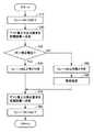
図7は、図4に示した制御装置180により実行されるリレー148の溶着判定処理を説明するためのフローチャートである。なお、このフローチャートの処理は、一定時間毎または所定の条件が成立する毎に実行される。 FIG. 7 is a flowchart for explaining the welding determination process of
図7を参照して、制御装置180は、まず、リレー144,148をいずれも非導通状態(オフ)に制御する(ステップS10)。次いで、制御装置180は、給電設備200から車両100へのテスト電力の出力要求を通信ユニット130を介して給電設備200へ送信する(ステップS20)。なお、このテスト電力の大きさは、リレー144,148が非導通状態(オフ)のときに車両100の受電回路の耐電圧を受電電圧が超えないように適宜設定される。 Referring to FIG. 7,
次いで、制御装置180は、電圧センサ190によって検出される電圧VRが規定電圧よりも高いか否かを判定する(ステップS30)。この規定電圧は、リレー148の溶着有無を判定するための電圧であり、以下のように決定される。すなわち、電圧センサ190のインピーダンスは大きいので(たとえば1MΩ程度)、リレー148が正常にオフされていれば、受電回路の耐電圧を超えない範囲で電圧VRは高い値となる。一方、リレー148が溶着していると、リレー148および抵抗146が導通するので、電圧VRは低い値となる。そこで、リレー148がオンしているときの電圧VRとリレー148がオフしているときの電圧VRとを区別可能なレベルに上記規定電圧が設定される。 Next, the
そして、ステップS30において電圧VRが規定電圧よりも高いと判定されると(ステップS30においてYES)、制御装置180は、リレー148を正常と判定する(ステップS40)。一方、ステップS30において電圧VRが規定電圧以下であると判定されると(ステップS30においてNO)、制御装置180は、リレー148が溶着しているものと判定する(ステップS50)。 If it is determined in step S30 that voltage VR is higher than the specified voltage (YES in step S30),
そして、ステップS40においてリレー148が正常と判定されるか、あるいはステップS50においてリレー148は溶着しているものと判定され、その後所定の異常処理が実行されると(ステップS60)、制御装置180は、テスト電力の停止要求を通信ユニット130を介して給電設備200へ送信する(ステップS70)。その後、制御装置180は、リレー144,148を非導通状態(オフ)に制御する(ステップS80)。 When it is determined in step S40 that relay 148 is normal or
以上のように、この実施の形態1においては、車両の位置合わせ用に抵抗146およびリレー148が設けられる。そして、リレー144,148が非導通状態(オフ)に制御され、かつ、給電設備200から車両100へ所定のテスト電力が送出されているとき、電圧センサ190により検出される電圧VRに基づいてリレー148の溶着有無が判定される。具体的には、電圧VRが規定電圧と比較され、電圧VRが規定電圧よりも高いときリレー148は正常と判定され、電圧VRが規定電圧以下のときリレー148が溶着しているものと判定される。したがって、この実施の形態1によれば、リレー148の溶着チェックを実施することができる。 As described above, in the first embodiment, the
[実施の形態2]
実施の形態1において、電圧センサ190のインピーダンスは大きいので、リレー148の溶着判定を行なうために給電設備200から送出されるテスト電力を上げることができない。そのため、リレー148が溶着している場合の電圧VRの検出値が小さくなり、リレー148が溶着しているのか、それとも、給電設備200からテスト電力が送電されていないのかを判別できなくなる可能性がある。[Embodiment 2]
In Embodiment 1, since the impedance of
そこで、この実施の形態2では、リレー148の溶着を判定する際に給電設備200から送出されるテスト電力を増加させるための方策が示される。 Therefore, in the second embodiment, a measure for increasing the test power sent from the
この実施の形態2における車両給電システムの全体構成は、図1に示した実施の形態1における車両給電システム10と同じである。 The overall configuration of the vehicle power feeding system in the second embodiment is the same as that of the vehicle
図8は、実施の形態2における受電回路を説明するための回路図である。なお、この図8は、実施の形態1における受電回路を説明した図5と対応するものである。図8を参照して、この実施の形態2では、直列に接続された抵抗146およびリレー148に並列に接続される抵抗149が設けられる。この抵抗149のインピーダンスは、抵抗146のインピーダンスよりも大きく、かつ、給電設備200からのテスト電力の受電時に受電回路の耐電圧を受電電圧が超えないように設計されている。一例として、抵抗146,149のインピーダンスは、それぞれ50Ω,10kΩに設計される。 FIG. 8 is a circuit diagram for illustrating a power receiving circuit in the second embodiment. FIG. 8 corresponds to FIG. 5 illustrating the power receiving circuit in the first embodiment. Referring to FIG. 8, in the second embodiment, a
なお、図8に示される受電回路のその他の構成は、図5に示した実施の形態1における受電回路の構成と同じである。 Note that the other configuration of the power receiving circuit illustrated in FIG. 8 is the same as the configuration of the power receiving circuit in Embodiment 1 illustrated in FIG.
この実施の形態2においては、抵抗146のインピーダンスよりも大きく、かつ、給電設備200からのテスト電力の受電時に受電回路の耐電圧を受電電圧が超えないように設計された抵抗149が設けられるので、実施の形態1と比較して、給電設備200から車両100へ出力するテスト電力を大きくすることができる。したがって、この実施の形態2によれば、電圧センサ190により検出される電圧VRに基づいて、リレー148の溶着チェックを確実に行なうことができる。 In the second embodiment, the
[実施の形態3]
この実施の形態3は、抵抗149(図8)を追加することなく、リレー148の溶着を判定する際に給電設備200から送出されるテスト電力を増加させるものである。この実施の形態3では、リレー148の溶着チェック時にDC/DCコンバータ142(図4,図5)を動作させ、DC/DCコンバータ142の入力インピーダンスが抵抗149のインピーダンスと同等になるようにDC/DCコンバータ142が制御される。[Embodiment 3]
In the third embodiment, the test power sent from the
この実施の形態3における車両給電システム10、車両100および給電設備200の全体構成は、実施の形態1と同じである。 The overall configuration of vehicle
図9は、実施の形態3における制御装置180により実行されるリレー148の溶着判定処理を説明するためのフローチャートである。なお、このフローチャートの処理も、一定時間毎または所定の条件が成立する毎に実行される。 FIG. 9 is a flowchart for illustrating welding determination processing of
図9を参照して、このフローチャートは、図7に示したフローチャートにおいて、ステップS14,S72をさらに含み、ステップS10に代えてステップS12を含む。すなわち、制御装置180は、まず、リレー144,148をそれぞれ導通状態(オン)および非導通状態(オフ)に制御する(ステップS12)。次いで、制御装置180は、充電器(DC/DCコンバータ142)を起動する(ステップS14)。その後、ステップS20へ処理が移行され、テスト電力の出力要求が通信ユニット130を介して給電設備200へ送信される。なお、テスト電力の受電時、制御装置180は、DC/DCコンバータ142の入力インピーダンスが抵抗149のインピーダンス(たとえば10kΩ)と同等になるようにDC/DCコンバータ142を制御する。 Referring to FIG. 9, this flowchart further includes steps S14 and S72 in the flowchart shown in FIG. 7, and includes step S12 instead of step S10. That is,
また、ステップS70においてテスト電力の停止要求が通信ユニット130を介して給電設備200へ送信されると、制御装置180は、充電器(DC/DCコンバータ142)を停止する(ステップS72)。その後、ステップS80へ処理が移行され、リレー144,148が非導通状態(オフ)に制御される。 Moreover, if the stop request | requirement of test electric power is transmitted to the electric
この実施の形態3においては、リレー148の溶着チェック時にDC/DCコンバータ142を動作させ、DC/DCコンバータ142の入力インピーダンスが、実施の形態2において設けられる抵抗149のインピーダンスと同等になるようにDC/DCコンバータ142が制御される。したがって、この実施の形態3によれば、抵抗149を設ける必要がないので、その分コストを抑えることができる。 In the third embodiment, the DC /
なお、上記の各実施の形態においては、一対の自己共振コイルを共鳴させて送電が行なわれるものとしたが、共鳴体として自己共振コイルに代えて高誘電率材から成る高誘電体ディスクを用いることもできる。 In each of the above embodiments, power is transmitted by resonating a pair of self-resonant coils. However, a high-dielectric disk made of a high dielectric constant material is used instead of the self-resonant coil as a resonator. You can also.
また、上記においては、電動車両として、動力分割装置177によりエンジン176の動力を分割して駆動輪178とモータジェネレータ172とに伝達可能なシリーズ/パラレル型のハイブリッド車について説明したが、この発明は、その他の形式のハイブリッド車にも適用可能である。すなわち、たとえば、モータジェネレータ172を駆動するためにのみエンジン176を用い、モータジェネレータ174でのみ車両の駆動力を発生する、いわゆるシリーズ型のハイブリッド車や、エンジン176が生成した運動エネルギーのうち回生エネルギーのみが電気エネルギーとして回収されるハイブリッド車、エンジンを主動力として必要に応じてモータがアシストするモータアシスト型のハイブリッド車などにもこの発明は適用可能である。 In the above description, a series / parallel type hybrid vehicle in which the power of the
また、この発明は、エンジン176を備えずに電力のみで走行する電気自動車や、直流電源として蓄電装置150に加えて燃料電池をさらに備える燃料電池車にも適用可能である。また、この発明は、昇圧コンバータ162を備えない電動車両や、DC/DCコンバータ142を備えない電動車両にも適用可能である。 In addition, the present invention can also be applied to an electric vehicle that does not include
なお、上記において、一次自己共振コイル234は、この発明における「送電用共鳴器」の一実施例に対応し、二次自己共振コイル112は、この発明における「受電用共鳴器」の一実施例に対応する。また、DC/DCコンバータ142は、この発明における「電気負荷」および「コンバータ」の一実施例に対応し、抵抗146は、この発明における「第1の抵抗」の一実施例に対応する。さらに、リレー148は、この発明における「リレー」の一実施例に対応し、制御装置180は、この発明における「判定部」の一実施例に対応する。また、さらに、抵抗149は、この発明における「第2の抵抗」の一実施例に対応し、制御装置180は、この発明における「制御部」の一実施例に対応する。 In the above description, primary self-
今回開示された実施の形態は、すべての点で例示であって制限的なものではないと考えられるべきである。本発明の範囲は、上記した実施の形態の説明ではなくて特許請求の範囲によって示され、特許請求の範囲と均等の意味および範囲内でのすべての変更が含まれることが意図される。 The embodiment disclosed this time should be considered as illustrative in all points and not restrictive. The scope of the present invention is shown not by the above description of the embodiments but by the scope of claims for patent, and is intended to include meanings equivalent to the scope of claims for patent and all modifications within the scope.
10 車両給電システム、100 車両、110 受電ユニット、112,340 二次自己共振コイル、114,350 二次コイル、120 カメラ、122 給電ボタン、130,240 通信ユニット、140 整流器、142 DC/DCコンバータ、144,148 リレー、146,149,211,506,508,510,512,516 抵抗、150 蓄電装置、162 昇圧コンバータ、164,166 インバータ、172,174 モータジェネレータ、176 エンジン、177 動力分割装置、178 駆動輪、180 制御装置、190 電圧センサ、200 給電設備、210 高周波電源装置、213 高周波交流電源、220 送電ユニット、230 発光部、232,320 一次コイル、234,330 一次自己共振コイル、310 高周波電源、360 負荷、410 IPA−ECU、420 EPS、430 MG−ECU、440 ECB、450 EPB、460 共鳴ECU、470 HV−ECU、502,504 入力端子、514 オペアンプ、518 出力端子、SMR1,SMR2 システムメインリレー。 DESCRIPTION OF
Claims (6)
Translated fromJapanese前記送電用共鳴器と前記電磁場を介して共鳴することにより前記送電用共鳴器から受電するように構成された受電用共鳴器と、
前記受電用共鳴器によって受電された電力の供給を受ける電気負荷と、
前記受電用共鳴器と前記電気負荷との間に配設される電力線対間に設けられ、直列に接続される第1の抵抗およびリレーと、
前記電力線対間の電圧を検出するための電圧センサとを備え、
前記リレーが非導通状態のとき、当該非接触受電装置の耐電圧を受電電圧が超えないように前記送電用共鳴器から前記受電用共鳴器へ所定の電力が送出され、さらに
前記リレーが非導通状態に制御され、かつ、前記送電用共鳴器から前記受電用共鳴器へ前記所定の電力が送出されているとき、前記電圧センサの検出値に基づいて前記リレーの溶着有無を判定する判定部を備える、非接触受電装置。A non-contact power receiving device that receives power from a power transmission resonator that receives electric power from a power source in a non-contact manner through the electromagnetic field,
A power receiving resonator configured to receive power from the power transmitting resonator by resonating with the power transmitting resonator via the electromagnetic field;
An electrical load that receives a supply of power received by the power receiving resonator; and
A first resistor and a relayprovided between a power line pair disposed between the power receiving resonator and the electric load, and connected in series;
A voltage sensor for detecting a voltage between the power line pair,
When the relay is in a non-conductive state, predetermined power is sent from the power transmitting resonator to the power receiving resonator so that the received voltage does not exceed the withstand voltage of the contactless power receiving device, and the relay is non-conductive A determination unit configured to determine whether or not the relay is welded based on a detection value of the voltage sensor when the predetermined power is transmitted from the power transmission resonator to the power reception resonator. A non-contact power receiving device.
前記電気負荷は、前記受電用共鳴器によって受電された電力を受けて前記蓄電装置を充電するように構成されたコンバータを含み、
前記制御部は、前記リレーが非導通状態に制御され、かつ、前記送電用共鳴器から前記受電用共鳴器へ前記所定の電力が送出されているとき、前記コンバータの入力インピーダンスが前記第1の抵抗の抵抗値よりも大きく、かつ、受電電圧が前記耐電圧を超えないように前記コンバータを制御する、請求項3に記載の非接触受電装置。A power storage device that stores electric power received by the power receiving resonator;
The electrical load includes a converter configured to receive the power received by the power receiving resonator and charge the power storage device,
The control unit is configured such that when the relay is controlled to be in a non-conductive state and the predetermined power is transmitted from the power transmission resonator to the power reception resonator, an input impedance of the converter is the first impedance. The non-contact power receiving apparatus according to claim 3, wherein the converter is controlled so as to be larger than a resistance value of the resistor and the received voltage does not exceed the withstand voltage.
前記非接触受電装置によって受電された電力を用いて走行トルクを発生する電動機とを備える電動車両。The non-contact power receiving device according to claim 1;
An electric vehicle comprising: an electric motor that generates a running torque using electric power received by the non-contact power receiving device.
Priority Applications (1)
| Application Number | Priority Date | Filing Date | Title |
|---|---|---|---|
| JP2009214211AJP5474463B2 (en) | 2009-09-16 | 2009-09-16 | Non-contact power receiving apparatus and electric vehicle including the same |
Applications Claiming Priority (1)
| Application Number | Priority Date | Filing Date | Title |
|---|---|---|---|
| JP2009214211AJP5474463B2 (en) | 2009-09-16 | 2009-09-16 | Non-contact power receiving apparatus and electric vehicle including the same |
Publications (2)
| Publication Number | Publication Date |
|---|---|
| JP2011066985A JP2011066985A (en) | 2011-03-31 |
| JP5474463B2true JP5474463B2 (en) | 2014-04-16 |
Family
ID=43952629
Family Applications (1)
| Application Number | Title | Priority Date | Filing Date |
|---|---|---|---|
| JP2009214211AExpired - Fee RelatedJP5474463B2 (en) | 2009-09-16 | 2009-09-16 | Non-contact power receiving apparatus and electric vehicle including the same |
Country Status (1)
| Country | Link |
|---|---|
| JP (1) | JP5474463B2 (en) |
Families Citing this family (17)
| Publication number | Priority date | Publication date | Assignee | Title |
|---|---|---|---|---|
| JP5696674B2 (en)* | 2012-02-17 | 2015-04-08 | トヨタ自動車株式会社 | Electric vehicle |
| JP5772687B2 (en)* | 2012-04-04 | 2015-09-02 | 株式会社Ihi | Power transmission system, power transmission device and power reception device, charging facility, and electric vehicle |
| US9931952B2 (en)* | 2012-06-27 | 2018-04-03 | Qualcomm Incorporated | Electric vehicle wireless charging with monitoring of duration of charging operational mode |
| JP5920185B2 (en)* | 2012-11-19 | 2016-05-18 | トヨタ自動車株式会社 | Non-contact power receiving device |
| JP6127668B2 (en)* | 2013-04-08 | 2017-05-17 | ソニー株式会社 | Electronic equipment and power supply system |
| WO2015004778A1 (en) | 2013-07-11 | 2015-01-15 | 株式会社Ihi | Power-transfer system |
| JP5962613B2 (en)* | 2013-08-08 | 2016-08-03 | トヨタ自動車株式会社 | Non-contact power receiving device |
| JP2015061404A (en)* | 2013-09-19 | 2015-03-30 | 株式会社豊田自動織機 | Secondary battery system |
| JP6252334B2 (en)* | 2014-04-22 | 2017-12-27 | 株式会社デンソー | Contactless power supply system |
| KR101673822B1 (en)* | 2015-11-18 | 2016-11-07 | 현대자동차주식회사 | Apparatus and method for detecting relay welding in green car |
| JP6724811B2 (en)* | 2017-02-07 | 2020-07-15 | トヨタ自動車株式会社 | Charging system |
| JP6312936B1 (en)* | 2017-04-24 | 2018-04-18 | 三菱電機エンジニアリング株式会社 | Resonant power receiver |
| KR102256097B1 (en)* | 2017-11-29 | 2021-05-25 | 주식회사 엘지에너지솔루션 | Battery back |
| KR102256100B1 (en)* | 2017-11-29 | 2021-05-25 | 주식회사 엘지에너지솔루션 | Battery back |
| KR102256099B1 (en)* | 2017-11-29 | 2021-05-25 | 주식회사 엘지에너지솔루션 | Battery back |
| KR102256095B1 (en)* | 2017-11-29 | 2021-05-25 | 주식회사 엘지에너지솔루션 | Battery back |
| CN107887227A (en)* | 2017-12-12 | 2018-04-06 | 蚌埠依爱电子科技有限责任公司 | A kind of relay drive signal method of calibration of breeding house environmental control |
Family Cites Families (10)
| Publication number | Priority date | Publication date | Assignee | Title |
|---|---|---|---|---|
| US5293308A (en)* | 1991-03-26 | 1994-03-08 | Auckland Uniservices Limited | Inductive power distribution system |
| JPH09130864A (en)* | 1995-11-02 | 1997-05-16 | Yuhshin Co Ltd | Remote controller |
| JPH11164497A (en)* | 1997-11-28 | 1999-06-18 | Shinko Electric Co Ltd | Non-contact feeder system |
| JP2002175750A (en)* | 2000-12-08 | 2002-06-21 | Toyota Motor Corp | Relay welding detector |
| JP4121972B2 (en)* | 2004-03-10 | 2008-07-23 | 三洋電機株式会社 | Inverter device |
| JP4495111B2 (en)* | 2006-05-10 | 2010-06-30 | 本田技研工業株式会社 | Contactor failure detection device in fuel cell system |
| JP2008236917A (en)* | 2007-03-20 | 2008-10-02 | Seiko Epson Corp | Non-contact power transmission device |
| JP4453741B2 (en)* | 2007-10-25 | 2010-04-21 | トヨタ自動車株式会社 | Electric vehicle and vehicle power supply device |
| US8421409B2 (en)* | 2008-09-19 | 2013-04-16 | Toyota Jidosha Kabushiki Kaisha | Noncontact power receiving apparatus for electrically-powered vehicle and vehicle including the same |
| BRPI0924914A2 (en)* | 2009-05-14 | 2016-08-30 | Toyota Motor Co Ltd | contactless energy capture equipment and vehicle incorporating the same |
- 2009
- 2009-09-16JPJP2009214211Apatent/JP5474463B2/ennot_activeExpired - Fee Related
Also Published As
| Publication number | Publication date |
|---|---|
| JP2011066985A (en) | 2011-03-31 |
Similar Documents
| Publication | Publication Date | Title |
|---|---|---|
| JP5474463B2 (en) | Non-contact power receiving apparatus and electric vehicle including the same | |
| JP5263391B2 (en) | Non-contact power receiving apparatus and vehicle equipped with the same | |
| KR101171024B1 (en) | Non-contact power reception device and vehicle including the same | |
| JP5152338B2 (en) | Non-contact charging device and non-contact power receiving device | |
| CN103561994B (en) | Vehicle and power transmission/receptisystem system | |
| JP5474470B2 (en) | Non-contact power receiving apparatus and electric vehicle including the same | |
| JP5083480B2 (en) | Non-contact power supply facility, vehicle, and control method for non-contact power supply system | |
| US9902271B2 (en) | Power feeding system for vehicle, electrically powered vehicle and power feeding apparatus for vehicle | |
| CN103561995B (en) | Vehicle, electrical equipment and electric power send by electricity system | |
| US20120098330A1 (en) | Coil unit, noncontact power receiving apparatus, noncontact power transmitting apparatus, noncontact power feeding system, and vehicle | |
| RU2461946C1 (en) | Device for non-contact power generation and transport means containing such device | |
| CN103522902A (en) | Non-contact powered device and vehicle provided with non-contact powered device | |
| JP5920185B2 (en) | Non-contact power receiving device | |
| JP2011244641A (en) | Non-contact power reception device for vehicle | |
| JP5962613B2 (en) | Non-contact power receiving device |
Legal Events
| Date | Code | Title | Description |
|---|---|---|---|
| A621 | Written request for application examination | Free format text:JAPANESE INTERMEDIATE CODE: A621 Effective date:20120905 | |
| A977 | Report on retrieval | Free format text:JAPANESE INTERMEDIATE CODE: A971007 Effective date:20131011 | |
| A131 | Notification of reasons for refusal | Free format text:JAPANESE INTERMEDIATE CODE: A131 Effective date:20131022 | |
| A521 | Request for written amendment filed | Free format text:JAPANESE INTERMEDIATE CODE: A523 Effective date:20131213 | |
| TRDD | Decision of grant or rejection written | ||
| A01 | Written decision to grant a patent or to grant a registration (utility model) | Free format text:JAPANESE INTERMEDIATE CODE: A01 Effective date:20140114 | |
| A61 | First payment of annual fees (during grant procedure) | Free format text:JAPANESE INTERMEDIATE CODE: A61 Effective date:20140205 | |
| R151 | Written notification of patent or utility model registration | Ref document number:5474463 Country of ref document:JP Free format text:JAPANESE INTERMEDIATE CODE: R151 | |
| R250 | Receipt of annual fees | Free format text:JAPANESE INTERMEDIATE CODE: R250 | |
| R250 | Receipt of annual fees | Free format text:JAPANESE INTERMEDIATE CODE: R250 | |
| LAPS | Cancellation because of no payment of annual fees |