JP5472979B2 - Chair - Google Patents
ChairDownload PDFInfo
- Publication number
- JP5472979B2 JP5472979B2JP2009197406AJP2009197406AJP5472979B2JP 5472979 B2JP5472979 B2JP 5472979B2JP 2009197406 AJP2009197406 AJP 2009197406AJP 2009197406 AJP2009197406 AJP 2009197406AJP 5472979 B2JP5472979 B2JP 5472979B2
- Authority
- JP
- Japan
- Prior art keywords
- back frame
- armrest
- frame
- wall
- horizontal beam
- Prior art date
- Legal status (The legal status is an assumption and is not a legal conclusion. Google has not performed a legal analysis and makes no representation as to the accuracy of the status listed.)
- Active
Links
- 238000009751slip formingMethods0.000claimsdescription4
- 239000004744fabricSubstances0.000description17
- 239000011162core materialSubstances0.000description5
- 230000002093peripheral effectEffects0.000description4
- 230000000149penetrating effectEffects0.000description3
- 239000000428dustSubstances0.000description2
- 239000000463materialSubstances0.000description2
- 125000006850spacer groupChemical group0.000description2
- 229920003002synthetic resinPolymers0.000description2
- 239000000057synthetic resinSubstances0.000description2
- 238000009940knittingMethods0.000description1
- 239000007769metal materialSubstances0.000description1
- 238000012986modificationMethods0.000description1
- 230000004048modificationEffects0.000description1
- 238000000465mouldingMethods0.000description1
- 238000009958sewingMethods0.000description1
- 239000000725suspensionSubstances0.000description1
- 238000009941weavingMethods0.000description1
Images


Landscapes
- Chair Legs, Seat Parts, And Backrests (AREA)
Description
Translated fromJapanese本発明は、左右対をなす背フレームと、肘掛けとを有する椅子に関する。 The present invention relates to a chair having a back frame that forms a pair of left and right sides and an armrest.
従来、肘掛けを有する椅子の肘掛けの支柱の取付態様として、肘当て面を有する肘当てから下方に延伸し、例えば左右に対をなす背フレームの下端部や、背フレームを支持する基体に直接取り付けられるものが知られている(例えば、特許文献1を参照)。 Conventionally, as an attachment mode of an armrest support of a chair having an armrest, it extends downward from an armrest having an elbow rest surface, and is directly attached to, for example, a lower end portion of a back frame that makes a pair on the left and right, or a base that supports the back frame. Are known (see, for example, Patent Document 1).
ところで、特許文献1記載のものに代表されるように、従来の構成では、肘掛けの支柱の下端部は座の下方に位置する。その一方で、肘掛けの肘当て面は座面よりも上方に位置するので、肘掛けの高さ寸法は大きなものとなる。 By the way, as represented by the thing of patent document 1, in the conventional structure, the lower end part of the support | pillar of an armrest is located under the seat. On the other hand, since the armrest surface of the armrest is located above the seat surface, the height dimension of the armrest is large.
従来の構成では、このように肘掛けの高さ寸法が大きなものとなるので、例えば肘当て面に着座者がもたれかかるなど、肘掛けに大きな外力が作用した場合に、支柱の下端部に大きな力が掛かり、肘掛けが損傷する不具合が発生しうる。 In the conventional configuration, the height of the armrest becomes large in this way.Therefore, when a large external force is applied to the armrest, for example, when a seated person leans against the armrest surface, a large force is applied to the lower end portion of the column. There is a possibility that the armrest and the armrest may be damaged.
本発明は以上の点に着目し、このような課題を解決すること、すなわち、肘掛けの取付強度を増し、肘掛けをより安定して取り付けるようにすることを目的とする。 The present invention pays attention to the above points and aims to solve such a problem, that is, to increase the mounting strength of the armrest and to mount the armrest more stably.
すなわち本発明に係る椅子は、背凭れに肘掛けの支柱を支持させてなり、前記背凭れが、左右対をなす背フレームと、前記背フレーム間に張設された張地と、前記背フレーム間に着脱可能に架設させた横梁とを具備するものであり、前記肘掛けの支柱が、前記横梁に一体に形成されている椅子であって、前記横梁が、その両端部に、背フレームの内側面に直接的または間接的に密着する取付壁と、前記各取付壁と協働して背フレームを挟持する外装壁とをそれぞれ備えており、止着具を用いて取付壁を対応する背フレームに止着していることを特徴とする。That chair according to the present invention,Ri Na by supporting the armrest struts backrest, the backrest includes a back frame forming a lateral pair, a coated cloth which is stretched between the back frame, the back frame The armrest strut is achair formed integrally with the transverse beam, and the transverse beam is attached toboth ends of the back frame. A back frame that includes a mounting wall that directly or indirectly adheres to the side surface and an exterior wall that sandwiches the back frame in cooperation with each of the mounting walls, and that corresponds to the mounting wall using fasteners. It is characterizedby being fixed to
このようなものであれば、肘掛けの支柱を背凭れの横梁と一体に形成していることにより、肘掛けの支柱が座の下方に達する従来の構成と比較して、肘掛けに大きな外力が作用した場合に支柱の下端部に掛かる力を小さくできる。また、肘掛けの支柱を背凭れの横梁と一体に形成することにより、部品点数の削減を図ることができる。
さらに、前記横梁が、その両端部に前記各取付壁と協働して背フレームを挟持する外装壁をそれぞれ備えているので、前記外装壁により前記取付壁と前記背フレームとの取付箇所を側方から隠蔽でき、このような椅子の見栄えを整えることができる。加えて、前記取付壁と前記外装壁との間の空間に背フレームを差し込むことにより、背フレームへの横梁及び肘掛けの取り付けを容易に行うことができる。If this is the case, by forming the armrest struts integrally with the backrest beam, a large external force was applied to the armrests compared to the conventional configuration in which the armrest struts reached below the seat. In this case, the force applied to the lower end of the column can be reduced. In addition, the number of parts can be reduced by forming the armrest struts integrally with the backrest beam.
Further, since the transverse beam includes an exterior wall that sandwiches the back frame in cooperation with each of the attachment walls at both ends thereof, the attachment location between the attachment wall and the back frame is located on the side by the exterior wall. It can be hidden from the side and the appearance of such a chair can be arranged. In addition, by inserting the back frame into the space between the mounting wall and the exterior wall, it is possible to easily attach the cross beam and the armrest to the back frame.
また、肘当ての背フレームへの取付強度を確保するには、前記取付壁が、前記背フレームに沿って伸びる形状をなしており、それら各取付壁をそれぞれ複数の止着具を用いて対応する背フレームに止着しているものが望ましい。また、このようなものであれば、前記取付壁により左右の背フレームに対して外方に向かう作用を与えた状態で前記取付壁と左右の背フレームとをそれぞれ止着することにより、背フレーム相互の取付強度も確保できる。Further, in order to ensure attachment strength of the back frame of theelbow, the front Symbol mounting wall, has a shape extending along the back frame, with their respective mounting wall plurality of fastening members Those fixed to the corresponding back frame are desirable. Further, in such a case, by attaching the mounting wall and the left and right back frames to each other in a state in which the mounting wall exerts an outward action on the left and right back frames, Mutual mounting strength can also be secured.
前段で述べたような椅子の見栄えをさらに整えるには、前記肘掛けが、前記外装壁と一体に連続形成されているものが望ましい。 In order to further improve the appearance of the chair as described in the previous stage, it is desirable that the armrest is continuously formed integrally with the exterior wall.
また、上述した取付壁及び外装壁を具備する椅子において、横梁及び肘掛けを背フレームにがたなく支持させるには、前記取付壁と前記外装壁とによって構成される嵌合部が、背フレームの起立した部分に沿って伸びる上下に長い形態をなしているものが望ましい。このようなものであれば、前記嵌合部に背フレームを差し込むようにすることで、背フレームのより長い部分に横梁及び肘掛けを接続できるからである。 Further, in the chair having the mounting wall and the exterior wall described above, in order to support the horizontal beam and the armrest without the back frame, the fitting portion constituted by the mounting wall and the exterior wall is provided on the back frame. It is desirable that the upper and lower parts extend along the standing part. If it is such, it is because a cross beam and an armrest can be connected to the longer part of a back frame by inserting a back frame in the said fitting part.
そして、着座者の腰部をより適切に支持できるようにするには、前記横梁が、着座者の腰形状に対応して前方に突出する背フレームの突出部の近傍同士を結合するのが望ましい。このようなものであれば、前記背フレームの突出部の近傍同士を横梁により結合することで、該部位の張地の張力を確保できるからである。 And in order to support a seated person's waist | hip | lumbar part more appropriately, it is desirable for the said cross beam to couple | bond the vicinity of the protrusion part of the back frame which protrudes ahead corresponding to a seated person's waist shape. If it is such, the tension | tensile_strength of the tension | tensile_strength of this site | part can be ensured by couple | bonding the vicinity of the protrusion part of the said back frame with a cross beam.
本発明の椅子の構成によれば、肘掛けの支柱を背凭れの横梁と一体に形成していることにより、肘掛けの支柱が座の下方に達する従来の構成と比較して、肘掛けに外力が作用した場合に支柱の下端部に掛かる力を小さくでき、このことにより肘掛けの背フレームへの取付強度を確保することができる。また、肘掛けの支柱を背凭れの横梁と一体に形成しているので、部品点数の削減を図ることもできる。 According to the configuration of the chair of the present invention, external force acts on the armrest as compared with the conventional configuration in which the armrest strut extends below the seat by forming the armrest strut integrally with the back beam. In this case, it is possible to reduce the force applied to the lower end portion of the support column, thereby securing the mounting strength of the armrest to the back frame. In addition, since the armrest support is formed integrally with the backrest beam, the number of parts can be reduced.
以下、本発明を事務用回転椅子に適用した場合の一実施形態について図1ないし図14を参照して説明する。 Hereinafter, an embodiment when the present invention is applied to an office rotary chair will be described with reference to FIGS.
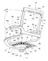
この椅子は、図1に示すように、脚体1と、この脚体1により回転可能に支持された支持基部3と、この支持基部3に支持された座5及び背凭れ7とを具備してなる。 As shown in FIG. 1, the chair includes a leg 1, a
脚体1は、図1に示すように、キャスタ9を有した脚羽根タイプの脚ベース11と、この脚ベース11の中心部に立設した脚支柱13とを具備してなる。前記脚支柱13は、ガススプリングを主体に構成された通常のもので、この脚支柱13の上端部に前記支持基部3が取り付けられている。 As shown in FIG. 1, the leg body 1 includes a leg blade
支持基部3は、図3ないし図8に示すように、後方に向かって漸次幅狭となる平面視ほぼ三角形状をなすものであり、前記脚支柱13の上端部に取り付けられる底壁3aと、この底壁3aの周縁に設けられた周壁3bと、この周壁3bの上端に蓋着された天壁3cとを具備してなる。この支持基部3には、前記脚体1のガススプリングを制御するための操作レバー3dが設けられている。 As shown in FIGS. 3 to 8, the
座5は、図1、図3、図6ないし図8に示すように、左右対をなす座フレーム15と、これら両座フレーム15間に張設された可撓性のある座張地17と、この座張地17との間に空間19を形成しつつ前記両座フレーム15の前端部15b間に介設されその介設状態で前記座張地17に張力を付与する前横梁21とを具備してなる。 As shown in FIGS. 1, 3, and 6 to 8, the
背凭れ7は、図1、図3、図6ないし図8に示すように、左右対をなす背フレーム23と、これら両背フレーム23間に張設された可撓性のある背張地25と、この背張地25との間に空間27を形成しつつ前記両背フレーム23の上部23a間に介設されその介設状態で前記背張地25に張力を付与する上横梁29と、前記背張地25との間に空間31を形成しつつ前記両背フレーム23の下部23b間に介設されその介設状態で前記背張地25に張力を付与する下横梁33とを具備してなる。 As shown in FIGS. 1, 3, and 6 to 8, the
前記座フレーム15と前記背フレーム23とは、図1ないし図8に示すように、連続したものであり(連続した座フレーム15と背フレーム23とを「フレームF」と総称する場合がある)、前記座5と背凭れ7とが一体となるように構成されている。すなわち、左の座フレーム15と左の背フレーム23、及び右の座フレーム15と右の背フレーム23とはそれぞれ一本の連続した金属素材を一体に成形することにより一体に構成されている。 The
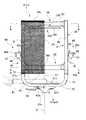
前記左のフレームF及び右のフレームFの各外側面Faには、図8ないし図10に示すように、前記座張地17及び前記背張地25を取り付けるための取付溝35が形成されている。これらの取付溝35は、前記各フレームFの裏面Fbよりも表面Fcに近い位置に配されている。ここで、裏面Fbとは、座フレーム15の場合には下面を意味し、背フレーム23の場合には背面を意味する。また、表面Fcとは、座フレーム15の場合には上面を意味し、背フレーム23の場合には前面を意味する。 As shown in FIGS. 8 to 10, mounting
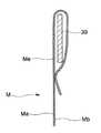
前記座張地17及び前記背張地25(以下、「張地M」と総称する場合がある)は、図1、図3、図6ないし図8、及び図11ないし図13に示すように、合成樹脂製の糸を織成または編成してなるメッシュ状の張地素材を所定形状に裁断することにより一体に構成されており、着座面である表面Ma側から裏面Mb側に存在するものを視認することができるような透光性を備えている。 As shown in FIG. 1, FIG. 3, FIG. 6 to FIG. 8, and FIG. 11 to FIG. 13, the
この張地Mの左右両縁部Mcには、図11及び図13に示すように、帯状をなす剛性のある押し込み材37が設けられている。この押し込み材37は、前記張地Mの縁部Mcに沿って連続して設けられたものであり、前記張地Mの縁部Mcの一面側、すなわち裏面Mb側に縫製等により添着されている。また、この押し込み材37は、合成樹脂等により作られたもので、前記取付溝35に挿入可能な厚み寸法T1を有するとともに、前記取付溝35の奥行き方向の開口寸法T1よりも大きな幅寸法W1を有したものである。 As shown in FIG. 11 and FIG. 13, the right and left edge portions Mc of the upholstery M are provided with a pushing
そして、図13に示すように、この張地Mの各縁部Mcを前記押し込み材37とともに前記フレームFの外面Fa側に設けられた取付溝35に反転させて挿入することにより、当該張地Mを左右のフレームF間に張設している。この状態で、左右のフレームF間に前横梁21、上横梁29及び下横梁33を介在させることによって前記張地Mに張力が付与される。このようにして張力を付与された張地Mは、左右のフレームFの形状に沿った形態となる。すなわち、左右の背フレーム23は、下端の近傍に着座者の腰形状に対応して前方に突出する突出部23cを有したものであり、前記背張地25が下横梁33により張力を付与されることにより前記突出部23cに対応した突出形状をなすように張設されている。 Then, as shown in FIG. 13, each edge Mc of the tension fabric M is inverted and inserted into the
また、前記張地Mの左右のフレームFに支持されていない縁部Md、Meは、図3、図11及び図12に示すように、袋状のものであり、その縁部Md、Me内に透明な芯材39が内蔵されている。具体的には、前記座5の前縁に位置する張地M(座張地17)の縁部Md及び前記背凭れ7の上縁に位置する張地M(背張地25)の縁部Meに芯材39がそれぞれ設けられている。これらの芯材39は、それぞれ透明なシート材を一定長さの帯状に裁断してなるもので、これら各芯材39の両端部39aと前記押し込み材37との間には芯材39が存在しない可撓変形部41を形成してなる。 Further, the edge portions Md and Me not supported by the left and right frames F of the upholstery M are bag-shaped as shown in FIGS. 3, 11 and 12, and the edges Md and Me A
前記前横梁21は、図3ないし図6に示すように、中間に略平坦な平坦部21aを有した正面視U字形をなしており、その左右両端部21bに左右の座フレーム15の内側面15aにそれぞれ直接的に密接する対をなす取付壁45を備えている。そして、これら各取付壁45をそれぞれ複数の止着具たるボルト47を用いて対応する座フレーム15に止着している。具体的には、この取付壁45に貫通させた2本のボルト47を前記座フレーム15に埋設したナット49に締着することにより、この取付壁45を前記座フレーム15に固定している。なお、前横梁21の両端部21bには、前記各取付壁45と協働して座フレーム15を挟持する外装壁51をそれぞれ備えている。前記取付壁45は、前記座フレーム15に沿って延びる形状をなしており、前記取付壁45と前記外装壁51とによって構成される嵌合部53が、座フレーム15に沿って延びる前後に長い形態をなしている。しかして、前記取付壁45は、その厚み寸法T2よりも座フレーム15に沿う方向の長手寸法L2が大きくなるように設定されている。 As shown in FIGS. 3 to 6, the
前記上横梁29は、図2ないし図7及び図10に示すように、その中央部29aが後方に突出するように湾曲したものであり、その左右両端部29bに左右の背フレーム23の内側面23dにそれぞれ直接的に密接する対をなす取付壁55を備えている。そして、これら各取付壁55をそれぞれ複数の止着具たるボルト57を用いて対応する背フレーム23に止着している。具体的には、この取付壁55に貫通させた2本のボルト57を前記背フレーム23に埋設したナット59に締着することにより、この取付壁55を前記背フレーム23に固定している。なお、上横梁29の両端部29bには、前記各取付壁55と協働して背フレーム23を挟持する外装壁61をそれぞれ備えている。前記取付壁55は、前記背フレーム23に沿って延びる形状をなしており、前記取付壁55と前記外装壁61とによって構成される嵌合部63が、背フレーム23に沿って延びる上下に長い形態をなしている。しかして、前記取付壁55は、その厚み寸法T3よりも背フレーム23に沿う方向の長手寸法L3が大きくなるように設定されている。 As shown in FIGS. 2 to 7 and 10, the upper
前記下横梁33は、図2ないし図7及び図9に示すように、着座者の腰形状に対応して前方に突出する背フレーム23の突出部23cの近傍同士を結合するものであって、その左右方向の中央部33aが後方に突出するように湾曲しており、その左右両端部33bに左右の背フレーム23の内側面23dにそれぞれ直接的に密接する対をなす取付壁65を備えている。そして、これら各取付壁65をそれぞれ複数の止着具たるボルト67を用いて対応する背フレーム23に止着している。具体的には、この取付壁65に貫通させた2本のボルト67を前記背フレーム23に埋設したナット69に締着することにより、この取付壁65を前記背フレーム23に固定している。なお、下横梁33の両端部33bには、前記各取付壁65と協働して背フレーム23を挟持する外装壁71をそれぞれ備えている。前記取付壁65は、前記背フレーム23に沿って延びる形状をなしており、前記取付壁65と前記外装壁71とによって構成される嵌合部73が、背フレーム23に沿って延びる上下に長い形態をなしている。しかして、前記取付壁65は、その厚み寸法T4よりも背フレーム23に沿う方向の長手寸法L4が大きくなるように設定されている。そして、この下横梁33部分において左右の背フレーム23をつなぐように、左右の背フレーム23と前記背フレーム23に沿う方向の長手寸法L4をもって固定するようにしている。なお、この下横梁33は、背フレーム23に対して着脱可能である。また、本実施形態においては、この下横梁33が本発明の請求項中の横梁である。 As shown in FIGS. 2 to 7 and 9, the lower
このようにしてなる本実施形態にかかる椅子は、図2及び図8に示すように、座5と背凭れ7とが一体に構成されており、これら座5及び背凭れ7が前記支持基部3に一体に設けられた前横梁21によって片持ち支持されている。そして、この支持基部3と前記座5との間に荷物載置面75が設けられ、その荷物載置面75と前記座5の裏面5aとの間に荷物B1を出し入れ自在に収容するための荷物収容空間77が形成されている。 As shown in FIGS. 2 and 8, the chair according to the present embodiment is configured such that the
前記荷物載置面75は、図2及び図3に示すように、平面視においてその外縁75aの一部が前記支持基部3の外縁3eよりも外側に位置する延出部79を備えており、その延出部79に埃排除手段81が設けられている。すなわち、この実施形態における荷物載置面75は、前横梁21の平坦部21aの上面21cと支持基部3の上に着脱可能に装着された棚板83の上面83aにより形成されている。換言すれば、前記支持基部3の上面3fを覆い隠すようにして前記棚板83が設けられており、その棚板83に前記荷物載置面75の主要部、すなわち荷物載置面75の一部が形成されている。 As shown in FIGS. 2 and 3, the
前記棚板83は、図2ないし図8に示すように、その上面83aで荷物B1を装脱可能に支持するための荷物載置面75の一部を形成する棚板本体85と、この棚板本体85の下面に設けられ前記支持基部3に着脱可能に外嵌される外嵌壁体87とを備えている。 As shown in FIGS. 2 to 8, the
前記棚板本体85は、前記支持基部3の上面3fに載置されるものであって、平面視において支持基部3よりも大きな面積を有しており、前記支持基部3よりも外側に位置する部位に前記埃排除手段81を構成する複数の貫通孔82が設けられている。この棚板本体85は、平面視においてA4版サイズよりも大きな面積を有したもので、その左右両側縁部85aに荷物B1の落下を防止するための湾曲部85bを備えている。この棚板本体85は、その中央部を前記脚支柱13の軸心である支持基部3の回転中心Oにほぼ一致させて配設されており、前記荷物載置面75が前記支持基部3の回転中心Oを含む位置に形成されるようにしている。 The shelf
前記外嵌壁体87は、前記支持基部3の外周面3gに重なり合う包持部87aと、前記支持基部3の底面周縁部分3hに重なり合う抜止部87bとを備えてなるもので、前記支持基部3に後方から装脱し得るようにその前面が開放されている。また、前記外嵌壁体87は、前記包持部87aの外面を前記棚板本体85の下面に接続するためのリブ87cを備えている。 The outer
また、この実施形態にかかる椅子は、図1に示すように、左右の肘掛け89を有している。この左右の肘掛け89は、腰部背面に位置する下横梁33と合わせて一体に成形している。さらに詳述すると、この肘掛け89は、図3ないし図5、図8、図14に示すように、前記下横梁33の外装壁71と一体に連続形成されたものであり、前記下横梁33の外面33cと前記肘掛け89の外面89aとが滑らかに一体化されている。この肘掛け89は、前記背凭れ7から前方に延出させて設けられたものであり、前記背凭れ7に支持された肘掛け本体91と、この肘掛け本体91上に設けられた肘当てパット93とを具備してなる。 Moreover, the chair concerning this embodiment has the
前記肘掛け本体91は、前記下横梁33に一体に設けられた肘支柱95と、この肘支柱95の先端部に設けられた肘フレーム97とからなり、この肘フレーム97上に前記肘当てパット93を装着している。具体的には、前記肘フレーム97が、その上面に前後対をなす取付部97aを有した硬質の下枠部97bと、この下枠部97bの取付部97aに前後両端部を取付けた硬質の上枠部97cとからなるもので、この下枠部97bと上枠部97cとで剛性を有したループ形状を形成している。換言すれば、この下枠部97bと前記上枠部97cとで窓部99が形成される。そして、上枠部97cの上に軟質の肘当てパット93を設けている。そして、この窓部99の開口縁99aに平面視において肘当てパット93の外縁93aからはみ出さない状態でかばんその他の荷物B2を掛けるためのフック101を設けている。すなわち、このフック101は、前記肘フレーム97の窓部99に一体に形成されている。換言すれば、このフック101は、前記窓部99の開口縁99aの下辺部分99bを変形させることにより形成されたものである。 The armrest
また、この実施形態にかかる椅子は、図2ないし図6に示すように、衣類を掛けるためのハンガー103を備えている。このハンガー103は、前記上横梁29の下辺29cに懸吊姿勢で一体的に設けられたものであり、衣類を掛けるためのハンガー本体105と、このハンガー本体105を前記上横梁29との間に隙間107を維持した状態で前記上横梁29に懸吊支持させる懸吊部材109とを具備してなる。 Moreover, the chair concerning this embodiment is provided with the
以上に述べたように、本実施形態に係る椅子の構成によれば、左右の肘掛け89を腰部背面に位置する下横梁33と合わせて一体に成形している、より具体的には、肘掛け93の肘支柱95を背凭れ7の下横梁33と一体に形成していることにより、肘掛けの支柱が座の下方に達する従来の構成と比較して、肘掛け93に大きな外力が作用した場合に肘支柱95の下端部に掛かる力を小さくでき、使用中に体重を掛けてもぐらつかない。さらに、このような構成であれば、少ない部品点数で肘掛け93を椅子に設けることができる。加えて、肘掛け93を有しない椅子との作り分けも、肘掛け93を有しする下横梁33と肘掛けを有しない下横梁とを用意し、必要に応じて選択して組み付けるだけなので、製品の作り分けが容易であり、肘掛け93を有する椅子と肘掛け93を有しない椅子との設計の共通化を図ることもできる。 As described above, according to the configuration of the chair according to the present embodiment, the left and
また、下横梁33部分において左右の背フレーム23をつなぐように、左右の背フレーム23とそれぞれ背フレーム23に沿う方向の長手寸法L4をもって固定されている、より具体的には、前記下横梁33がその両端部に前記背フレーム23の内側面23dに直接的に密接する取付壁65を備え、これら取付壁65が前記背フレーム23に沿って伸びる形状をなし、さらに各取付壁65をそれぞれ複数のボルト67を用いて対応する背フレーム23に止着しているので、この下横梁33と一体に形成した肘当て69の背フレーム23への取付強度を確保することができる。従って、より確実に使用中に体重を掛けてもぐらつかないようにできる。また、前記取付壁65により左右の背フレーム23に対して外方に向かう作用を与えた状態で前記取付壁65と左右の背フレーム23とをそれぞれ止着することにより、背フレーム相互の取付強度も確保できる。 The lower
さらに、前記下横梁33が、その両端部に前記各取付壁65と協働して背フレーム23を挟持する外装壁71をそれぞれ備えているので、前記外装壁71により前記取付壁65と前記背フレーム23との取付箇所を側方から隠蔽し、この椅子の見栄えを整えることができる。また、前記取付壁65と前記外装壁71との間の空間に背フレーム23を差し込むことにより、背フレーム23への横梁33及び肘掛け69の取り付けを容易に行うことができる。 Further, since the lower
加えて、前記肘掛け69が、前記外装壁71と一体に連続形成されているので、この点からも椅子の見栄えをさらに整えることができる。 In addition, since the
また、前記取付壁65と前記外装壁71とによって構成される嵌合部73が、背フレーム23の起立した部分に沿って伸びる上下に長い形態をなしているので、この嵌合部73に背フレーム23を差し込むようにすることで、背フレーム23のより長い部分に下横梁33及びこの下横梁33と一体に形成した肘掛け69を接続し、これら下横梁33及び肘掛け69を背フレーム23にがたなく支持させることができる。 Further, since the
そして、前記下横梁33が、着座者の腰形状に対応して前方に突出する背フレーム23の突出部23cの近傍同士を結合するので、該部位の背張地25の張力を高くでき、従って、この椅子に着座した着座者の腰部をより適切に支持できる。 And since the said lower
なお、本発明は以上に述べた実施形態に限らない。 The present invention is not limited to the embodiment described above.
例えば、肘掛けと一体に形成した横梁は、左右の背フレームの突出部近傍に限らず、左右の背フレームの他の箇所同士を結合するものであってもよい。 For example, the cross beam formed integrally with the armrest is not limited to the vicinity of the protruding portions of the left and right back frames, and may be one that connects other portions of the left and right back frames.
また、上述した実施形態においては前記取付壁と前記外装壁とが協働して背フレームを挟持するようにしているが、外装壁は省略してもよい。また、横梁及び肘掛けとは別体の外装壁を横梁又は肘掛けに取り付けるようにしてもよい。 In the embodiment described above, the mounting wall and the exterior wall cooperate to sandwich the back frame, but the exterior wall may be omitted. Moreover, you may make it attach an exterior wall separate from a cross beam and an armrest to a cross beam or an armrest.
さらに、前記取付壁と前記外装壁とによって構成される嵌合部を、背フレームの起立した部分に沿って伸びる上下に長い形態をなすようにする代わりに、例えば背フレームの突出部の形状に沿うように形成してもよい。 Furthermore, instead of making the fitting portion constituted by the mounting wall and the exterior wall have a vertically long shape extending along the upright portion of the back frame, for example, in the shape of a protruding portion of the back frame You may form so that it may follow.
加えて、横梁の取付壁を背フレームに止着する際に、止着具を1つだけ設けるようにしてもよい。 In addition, when fastening the mounting wall of the cross beam to the back frame, only one fastening tool may be provided.
さらに、前横梁、上横梁、及び下横梁は、それぞれフレームに直接的に取り付けられたものに限らず、図15に示すように、各横梁21、29、33をフレームFに間接的に取り付けられるものであってもよい。すなわち、各横梁21、29、33の取付壁45、55、65とフレームFとの間に隙間を設け、その隙間にスペーサS等の介在部材を設けるものであってもよい。このようなものであれば、介在させるスペーサSの厚みを種々変更することにより、張地Mの張力を調節することができる。一方、前記前横梁、上横梁、及び下横梁の取付壁自体を省略してもかまわない。 Further, the front transverse beam, the upper transverse beam, and the lower transverse beam are not limited to those directly attached to the frame, but the respective
そして、上述した実施形態では、背フレームと座フレームとを連続させて一体に形成しているが、背フレームと座フレームとを別体に形成した椅子に本発明を適用してもよい。この場合、背凭れの後傾につれ座の後部が下方に沈み込むシンクロチルト機構を有するものであってもよい。 In the above-described embodiment, the back frame and the seat frame are continuously formed integrally. However, the present invention may be applied to a chair in which the back frame and the seat frame are formed separately. In this case, it may have a synchro tilt mechanism in which the rear part of the seat sinks downward as the backrest tilts backward.
その他、本発明の趣旨を損ねない範囲で種々に変形してよい。 In addition, various modifications may be made without departing from the spirit of the present invention.
1…脚体
3…支持基部
5…座
7…背凭れ1 ...
Claims (5)
Translated fromJapanese前記背凭れが、左右対をなす背フレームと、前記背フレーム間に張設された張地と、前記背フレーム間に着脱可能に架設させた横梁とを具備するものであり、前記肘掛けの支柱が、前記横梁に一体に形成されている椅子であって、
前記横梁が、その両端部に、背フレームの内側面に直接的または間接的に密着する取付壁と、前記各取付壁と協働して背フレームを挟持する外装壁とをそれぞれ備えており、止着具を用いて取付壁を対応する背フレームに止着していることを特徴とする椅子。Ri name and is supported by the armrest of the strut to the backrest,
The backrest includes a back frame that forms a pair of left and right sides, a tension ground stretched between the back frames, and a horizontal beam that is detachably laid between the back frames. Is achair formed integrally with the cross beam,
The horizontal beam includes, at both ends thereof, an attachment wall that directly or indirectly adheres to the inner surface of the back frame, and an exterior wall that sandwiches the back frame in cooperation with each of the attachment walls, A chair characterizedin that a mounting wall is fastened to a corresponding back frame using a fastening tool .
Priority Applications (1)
| Application Number | Priority Date | Filing Date | Title |
|---|---|---|---|
| JP2009197406AJP5472979B2 (en) | 2009-08-27 | 2009-08-27 | Chair |
Applications Claiming Priority (1)
| Application Number | Priority Date | Filing Date | Title |
|---|---|---|---|
| JP2009197406AJP5472979B2 (en) | 2009-08-27 | 2009-08-27 | Chair |
Publications (2)
| Publication Number | Publication Date |
|---|---|
| JP2011045577A JP2011045577A (en) | 2011-03-10 |
| JP5472979B2true JP5472979B2 (en) | 2014-04-16 |
Family
ID=43832499
Family Applications (1)
| Application Number | Title | Priority Date | Filing Date |
|---|---|---|---|
| JP2009197406AActiveJP5472979B2 (en) | 2009-08-27 | 2009-08-27 | Chair |
Country Status (1)
| Country | Link |
|---|---|
| JP (1) | JP5472979B2 (en) |
Family Cites Families (4)
| Publication number | Priority date | Publication date | Assignee | Title |
|---|---|---|---|---|
| KR100334315B1 (en)* | 1992-06-15 | 2002-10-11 | 헤르만밀러인코퍼레이티드 | Slope control device for office |
| JP2004041493A (en)* | 2002-07-12 | 2004-02-12 | Kanto Auto Works Ltd | Armrest of wheelchair |
| US6896328B2 (en)* | 2002-12-18 | 2005-05-24 | Hon Technology Inc. | Steel wire chair with springs |
| JP2007296077A (en)* | 2006-04-28 | 2007-11-15 | Okamura Corp | Backrest support frame of chair |
- 2009
- 2009-08-27JPJP2009197406Apatent/JP5472979B2/enactiveActive
Also Published As
| Publication number | Publication date |
|---|---|
| JP2011045577A (en) | 2011-03-10 |
Similar Documents
| Publication | Publication Date | Title |
|---|---|---|
| JP5263802B2 (en) | Chair | |
| JP5005167B2 (en) | Chair backrest structure | |
| US7017985B2 (en) | Folding chair with arms | |
| KR20180116730A (en) | Multi-purpose structure changeable chair | |
| JP2011045567A (en) | Swivel chair | |
| JP5138252B2 (en) | Cover mounting structure on back plate of chair | |
| JP2015093028A (en) | Chair | |
| JP5472979B2 (en) | Chair | |
| CN104287500A (en) | Internal support for backrest for chair | |
| JP5424199B2 (en) | Chair | |
| JP2013198565A (en) | Backrest for chair | |
| JP2011045573A (en) | Chair | |
| JP2012135453A (en) | Chair | |
| JP2011045575A (en) | Chair | |
| JP2011045570A (en) | Swivel chair | |
| JP4516822B2 (en) | Chair | |
| JP2011045571A (en) | Chair | |
| JP5496985B2 (en) | Chair backrest structure | |
| JP5472978B2 (en) | Swivel chair | |
| CN110025159A (en) | The outer removable sofa of frame handrail | |
| JP2011045572A (en) | Chair | |
| JP2014226329A (en) | Chair | |
| JP5625177B2 (en) | Chair | |
| JP7172378B2 (en) | Chair | |
| JP4652761B2 (en) | Reclining chair |
Legal Events
| Date | Code | Title | Description |
|---|---|---|---|
| A621 | Written request for application examination | Free format text:JAPANESE INTERMEDIATE CODE: A621 Effective date:20120723 | |
| A977 | Report on retrieval | Free format text:JAPANESE INTERMEDIATE CODE: A971007 Effective date:20131024 | |
| A131 | Notification of reasons for refusal | Free format text:JAPANESE INTERMEDIATE CODE: A131 Effective date:20131029 | |
| A521 | Request for written amendment filed | Free format text:JAPANESE INTERMEDIATE CODE: A523 Effective date:20131216 | |
| TRDD | Decision of grant or rejection written | ||
| A01 | Written decision to grant a patent or to grant a registration (utility model) | Free format text:JAPANESE INTERMEDIATE CODE: A01 Effective date:20140114 | |
| A61 | First payment of annual fees (during grant procedure) | Free format text:JAPANESE INTERMEDIATE CODE: A61 Effective date:20140130 | |
| R150 | Certificate of patent or registration of utility model | Ref document number:5472979 Country of ref document:JP Free format text:JAPANESE INTERMEDIATE CODE: R150 | |
| S111 | Request for change of ownership or part of ownership | Free format text:JAPANESE INTERMEDIATE CODE: R313117 | |
| SZ03 | Written request for cancellation of trust registration | Free format text:JAPANESE INTERMEDIATE CODE: R313Z03 | |
| R350 | Written notification of registration of transfer | Free format text:JAPANESE INTERMEDIATE CODE: R350 | |
| S111 | Request for change of ownership or part of ownership | Free format text:JAPANESE INTERMEDIATE CODE: R313115 | |
| R350 | Written notification of registration of transfer | Free format text:JAPANESE INTERMEDIATE CODE: R350 | |
| R250 | Receipt of annual fees | Free format text:JAPANESE INTERMEDIATE CODE: R250 | |
| R250 | Receipt of annual fees | Free format text:JAPANESE INTERMEDIATE CODE: R250 | |
| R250 | Receipt of annual fees | Free format text:JAPANESE INTERMEDIATE CODE: R250 | |
| R250 | Receipt of annual fees | Free format text:JAPANESE INTERMEDIATE CODE: R250 |