JP5471674B2 - projector - Google Patents
projectorDownload PDFInfo
- Publication number
- JP5471674B2 JP5471674B2JP2010065840AJP2010065840AJP5471674B2JP 5471674 B2JP5471674 B2JP 5471674B2JP 2010065840 AJP2010065840 AJP 2010065840AJP 2010065840 AJP2010065840 AJP 2010065840AJP 5471674 B2JP5471674 B2JP 5471674B2
- Authority
- JP
- Japan
- Prior art keywords
- light
- illumination
- polarization separation
- liquid crystal
- angular distribution
- Prior art date
- Legal status (The legal status is an assumption and is not a legal conclusion. Google has not performed a legal analysis and makes no representation as to the accuracy of the status listed.)
- Expired - Fee Related
Links
- 230000010287polarizationEffects0.000claimsdescription161
- 238000000926separation methodMethods0.000claimsdescription139
- 238000005286illuminationMethods0.000claimsdescription117
- 239000004973liquid crystal related substanceSubstances0.000claimsdescription101
- 230000003287optical effectEffects0.000claimsdescription93
- 230000000737periodic effectEffects0.000description27
- 238000006243chemical reactionMethods0.000description9
- 230000000052comparative effectEffects0.000description8
- 230000004048modificationEffects0.000description8
- 238000012986modificationMethods0.000description8
- 238000005452bendingMethods0.000description7
- 230000008859changeEffects0.000description7
- 230000004907fluxEffects0.000description7
- 238000003491arrayMethods0.000description6
- 230000015572biosynthetic processEffects0.000description4
- 230000007423decreaseEffects0.000description4
- 239000000758substrateSubstances0.000description4
- 238000003786synthesis reactionMethods0.000description4
- 230000008033biological extinctionEffects0.000description3
- 238000012937correctionMethods0.000description3
- 230000003247decreasing effectEffects0.000description3
- 238000010586diagramMethods0.000description3
- 230000010363phase shiftEffects0.000description3
- 239000003086colorantSubstances0.000description2
- 230000000593degrading effectEffects0.000description2
- 230000006866deteriorationEffects0.000description2
- 238000000034methodMethods0.000description2
- 230000029553photosynthesisEffects0.000description2
- 238000010672photosynthesisMethods0.000description2
- 230000008901benefitEffects0.000description1
- 230000000903blocking effectEffects0.000description1
- 239000004020conductorSubstances0.000description1
- 238000010030laminatingMethods0.000description1
- 239000011159matrix materialSubstances0.000description1
- 230000007246mechanismEffects0.000description1
- QSHDDOUJBYECFT-UHFFFAOYSA-NmercuryChemical compound[Hg]QSHDDOUJBYECFT-UHFFFAOYSA-N0.000description1
- 229910052753mercuryInorganic materials0.000description1
- 239000004038photonic crystalSubstances0.000description1
- 210000001747pupilAnatomy0.000description1
- 230000009467reductionEffects0.000description1
- 230000003068static effectEffects0.000description1
- 230000002194synthesizing effectEffects0.000description1
- 238000002834transmittanceMethods0.000description1
Images


Classifications
- G—PHYSICS
- G03—PHOTOGRAPHY; CINEMATOGRAPHY; ANALOGOUS TECHNIQUES USING WAVES OTHER THAN OPTICAL WAVES; ELECTROGRAPHY; HOLOGRAPHY
- G03B—APPARATUS OR ARRANGEMENTS FOR TAKING PHOTOGRAPHS OR FOR PROJECTING OR VIEWING THEM; APPARATUS OR ARRANGEMENTS EMPLOYING ANALOGOUS TECHNIQUES USING WAVES OTHER THAN OPTICAL WAVES; ACCESSORIES THEREFOR
- G03B21/00—Projectors or projection-type viewers; Accessories therefor
- G03B21/14—Details
- G—PHYSICS
- G03—PHOTOGRAPHY; CINEMATOGRAPHY; ANALOGOUS TECHNIQUES USING WAVES OTHER THAN OPTICAL WAVES; ELECTROGRAPHY; HOLOGRAPHY
- G03B—APPARATUS OR ARRANGEMENTS FOR TAKING PHOTOGRAPHS OR FOR PROJECTING OR VIEWING THEM; APPARATUS OR ARRANGEMENTS EMPLOYING ANALOGOUS TECHNIQUES USING WAVES OTHER THAN OPTICAL WAVES; ACCESSORIES THEREFOR
- G03B33/00—Colour photography, other than mere exposure or projection of a colour film
- G03B33/10—Simultaneous recording or projection
- G03B33/12—Simultaneous recording or projection using beam-splitting or beam-combining systems, e.g. dichroic mirrors
- G—PHYSICS
- G03—PHOTOGRAPHY; CINEMATOGRAPHY; ANALOGOUS TECHNIQUES USING WAVES OTHER THAN OPTICAL WAVES; ELECTROGRAPHY; HOLOGRAPHY
- G03B—APPARATUS OR ARRANGEMENTS FOR TAKING PHOTOGRAPHS OR FOR PROJECTING OR VIEWING THEM; APPARATUS OR ARRANGEMENTS EMPLOYING ANALOGOUS TECHNIQUES USING WAVES OTHER THAN OPTICAL WAVES; ACCESSORIES THEREFOR
- G03B21/00—Projectors or projection-type viewers; Accessories therefor
- G03B21/005—Projectors using an electronic spatial light modulator but not peculiar thereto
- G03B21/006—Projectors using an electronic spatial light modulator but not peculiar thereto using LCD's
- G—PHYSICS
- G03—PHOTOGRAPHY; CINEMATOGRAPHY; ANALOGOUS TECHNIQUES USING WAVES OTHER THAN OPTICAL WAVES; ELECTROGRAPHY; HOLOGRAPHY
- G03B—APPARATUS OR ARRANGEMENTS FOR TAKING PHOTOGRAPHS OR FOR PROJECTING OR VIEWING THEM; APPARATUS OR ARRANGEMENTS EMPLOYING ANALOGOUS TECHNIQUES USING WAVES OTHER THAN OPTICAL WAVES; ACCESSORIES THEREFOR
- G03B21/00—Projectors or projection-type viewers; Accessories therefor
- G03B21/14—Details
- G03B21/20—Lamp housings
- G03B21/2053—Intensity control of illuminating light
- G—PHYSICS
- G03—PHOTOGRAPHY; CINEMATOGRAPHY; ANALOGOUS TECHNIQUES USING WAVES OTHER THAN OPTICAL WAVES; ELECTROGRAPHY; HOLOGRAPHY
- G03B—APPARATUS OR ARRANGEMENTS FOR TAKING PHOTOGRAPHS OR FOR PROJECTING OR VIEWING THEM; APPARATUS OR ARRANGEMENTS EMPLOYING ANALOGOUS TECHNIQUES USING WAVES OTHER THAN OPTICAL WAVES; ACCESSORIES THEREFOR
- G03B21/00—Projectors or projection-type viewers; Accessories therefor
- G03B21/14—Details
- G03B21/20—Lamp housings
- G03B21/206—Control of light source other than position or intensity
- G—PHYSICS
- G03—PHOTOGRAPHY; CINEMATOGRAPHY; ANALOGOUS TECHNIQUES USING WAVES OTHER THAN OPTICAL WAVES; ELECTROGRAPHY; HOLOGRAPHY
- G03B—APPARATUS OR ARRANGEMENTS FOR TAKING PHOTOGRAPHS OR FOR PROJECTING OR VIEWING THEM; APPARATUS OR ARRANGEMENTS EMPLOYING ANALOGOUS TECHNIQUES USING WAVES OTHER THAN OPTICAL WAVES; ACCESSORIES THEREFOR
- G03B21/00—Projectors or projection-type viewers; Accessories therefor
- G03B21/14—Details
- G03B21/20—Lamp housings
- G03B21/2073—Polarisers in the lamp house
- H—ELECTRICITY
- H04—ELECTRIC COMMUNICATION TECHNIQUE
- H04N—PICTORIAL COMMUNICATION, e.g. TELEVISION
- H04N9/00—Details of colour television systems
- H04N9/12—Picture reproducers
- H04N9/31—Projection devices for colour picture display, e.g. using electronic spatial light modulators [ESLM]
- H04N9/3141—Constructional details thereof
- H04N9/315—Modulator illumination systems
- H04N9/3167—Modulator illumination systems for polarizing the light beam
Landscapes
- Physics & Mathematics (AREA)
- General Physics & Mathematics (AREA)
- Engineering & Computer Science (AREA)
- Multimedia (AREA)
- Signal Processing (AREA)
- Projection Apparatus (AREA)
- Liquid Crystal (AREA)
- Polarising Elements (AREA)
Description
Translated fromJapanese本発明は、液晶パネルと構造性複屈折型の偏光分離素子とを有する光変調装置によって変調された光束を画像として投射するプロジェクターに関する。 The present invention relates to a projector that projects a light beam modulated by a light modulation device having a liquid crystal panel and a structural birefringent polarization separation element as an image.
プロジェクターとして、反射型液晶パネルに対向する位置にワイヤグリッド偏光分離素子を光軸に対して45°傾けて配置し、ワイヤグリッド偏光分離素子を透過させた偏光を反射型液晶パネルに入射させるとともに、反射型液晶パネルで反射された変調光をワイヤグリッド偏光分離素子で反射して分岐するものがある(特許文献1参照)。 As a projector, the wire grid polarization separation element is disposed at a position facing the reflection type liquid crystal panel at an angle of 45 ° with respect to the optical axis, and the polarized light transmitted through the wire grid polarization separation element is incident on the reflection type liquid crystal panel. There is one in which modulated light reflected by a reflective liquid crystal panel is reflected by a wire grid polarization separation element and branched (see Patent Document 1).
また、別のプロジェクターとして、照明光束の減光量を回動によって調整する遮光部材を有する絞り機構を備え、遮光部材に例えばスリット状に形成された開口部を設けることにより、最も遮光した状態でも一部の光束を比較的均等に通過させるようにしたものがある(特許文献2参照)。 In addition, as another projector, a diaphragm mechanism having a light shielding member that adjusts the light reduction amount of the illumination light beam by rotation is provided, and an opening formed in a slit shape, for example, is provided on the light shielding member, so that even in the most light-shielded state. There is one in which the light flux of the portion is allowed to pass relatively evenly (see Patent Document 2).
しかしながら、特許文献1のプロジェクターでは、照明光束の角度分布について考慮されておらず、投射像のコントラストの向上が十分に達成されていない。すなわち、本発明者は、上記のようなプロジェクターでは、ワイヤグリッド偏光分離素子を用いているため、照明光束の角度分布が投射像のコントラストに影響することを確認しており、照明光束の角度分布の設定次第でコントラスト向上の余地があることを見いだした。 However, in the projector of
また、特許文献2のプロジェクターでは、調光時に照明光の均一性を維持しやすくなるが、投射像のコントラストを維持・向上させることは必ずしも容易でない。 In the projector of Patent Document 2, it is easy to maintain the uniformity of illumination light during light control, but it is not always easy to maintain and improve the contrast of the projected image.
そこで、本発明は、投射像のコントラストを向上させることができ、或いは、調光に際してコントラストの劣化を抑えることができるプロジェクターを提供することを目的とする。 SUMMARY An advantage of some aspects of the invention is that it provides a projector that can improve the contrast of a projected image or can suppress deterioration of contrast during light control.
上記課題を解決するため、本発明に係る第1のプロジェクターは、照明光を射出する照明装置と、液晶パネルと、照明光の中心軸に対して傾斜して配置される偏光分離面を有する構造性複屈折型の偏光分離素子とを有し、照明装置からの照明光を変調する光変調装置と、光変調装置によって変調された光を投射する投射光学系と、を備え、照明装置は、照明光の中心軸に直交する第1方向に関する角度分布が第1方向及び照明光の中心軸に直交する第2方向に関する角度分布よりも小さい状態の照明光を射出し、構造性複屈折型の偏光分離素子の偏光分離面は、第1方向に沿って非周期的であり第2方向に沿って周期的に繰り返される構造を有する。なお、第1方向や第2方向は、光路を展開した場合を基準として考えるものとする。 In order to solve the above-described problem, a first projector according to the present invention has a structure having an illumination device that emits illumination light, a liquid crystal panel, and a polarization separation surface that is arranged to be inclined with respect to the central axis of the illumination light. A birefringent polarization separation element, and includes a light modulation device that modulates illumination light from the illumination device, and a projection optical system that projects light modulated by the light modulation device. Illumination light in a state where the angular distribution with respect to the first direction orthogonal to the central axis of the illumination light is smaller than the angular distribution with respect to the first direction and the second direction orthogonal to the central axis of the illumination light is emitted, and the structural birefringence type The polarization separation surface of the polarization separation element has a structure that is aperiodic along the first direction and periodically repeated along the second direction. Note that the first direction and the second direction are considered based on the case where the optical path is developed.
上記プロジェクターによれば、照明装置が、第1方向に関する角度分布が第2方向に関する角度分布よりも小さい状態の照明光を射出し、構造性複屈折型の偏光分離素子の偏光分離面が、第1方向に沿って非周期的であり第2方向に沿って周期的に繰り返される構造を有するので、構造性複屈折型の偏光分離素子に入射する照明光は、第1方向に関する角度範囲が第2方向に関する角度範囲に比較して相対的に狭くなる。これにより、構造性複屈折型の偏光分離素子の偏光分離特性を良好なものとすることができ、構造性複屈折型の偏光分離素子による光漏れを低減できるので、投射画像のコントラストを高めることができる。 According to the projector, the illumination device emits illumination light in a state where the angular distribution in the first direction is smaller than the angular distribution in the second direction, and the polarization separation surface of the structural birefringence polarization separation element is Since it has a structure that is aperiodic along one direction and periodically repeated along the second direction, the illumination light incident on the structural birefringent polarization separation element has an angular range in the first direction. Compared to the angle range in two directions, it becomes relatively narrow. As a result, the polarization separation characteristic of the structural birefringence type polarization separation element can be improved, and light leakage due to the structural birefringence type polarization separation element can be reduced, thereby increasing the contrast of the projected image. Can do.
また、本発明の具体的な態様又は側面によれば、上記プロジェクターにおいて、照明装置が、照明光の角度分布を調節する可動の遮光部を有する調光装置を備える。この場合、可動の遮光部を有する調光装置によって、照明光の角度分布を調節することができ、投射画像のコントラストを向上させつつ明るさを増減調節することができる。 According to a specific aspect or aspect of the present invention, in the projector, the illumination device includes a light control device having a movable light-shielding unit that adjusts an angular distribution of illumination light. In this case, the angle distribution of the illumination light can be adjusted by the light control device having the movable light-shielding unit, and the brightness can be increased or decreased while improving the contrast of the projection image.
本発明の別の側面によれば、照明装置が、照明光の角度分布を制限する遮光部を有する固定型の絞りを備える。この場合、遮光部を有する固定型の絞りによって、構造性複屈折型の偏光分離素子に入射する照明光の角度分布を漏れ光防止に効果的な方向に関して制限することができ、投射画像のコントラストを恒常的に高めることができる。 According to another aspect of the present invention, the illuminating device includes a fixed diaphragm having a light blocking portion that restricts the angular distribution of the illumination light. In this case, the angled distribution of the illumination light incident on the structural birefringence type polarization separation element can be limited with respect to the direction effective for preventing leakage light by the fixed diaphragm having the light shielding portion, and the contrast of the projected image Can be constantly increased.
本発明の別の側面によれば、遮光部が、第1方向の幅が第2方向の位置によって異なる開口を有する。この場合、第2方向又は周期方向の位置によって構造性複屈折型の偏光分離素子に入射する照明光に対する光漏れの程度が異なる場合であっても、このような光漏れの差を相殺するような角度分布の照明光を構造性複屈折型の偏光分離素子に入射させることができ、投射画像のコントラストを一様に向上させることができる。 According to another aspect of the present invention, the light-shielding portion has an opening whose width in the first direction varies depending on the position in the second direction. In this case, even if the degree of light leakage with respect to the illumination light incident on the structural birefringence type polarization separation element differs depending on the position in the second direction or the periodic direction, such a difference in light leakage is canceled out. Illumination light having an angular distribution can be made incident on the structural birefringent polarization separation element, and the contrast of the projected image can be improved uniformly.
本発明の別の側面によれば、上記光変調装置とは別の複数の光変調装置と、照明装置から射出された照明光を赤光、緑光、及び青光に分離し、緑光を上記光変調装置に導き、赤光及び青光を上記別の複数の光変調装置にそれぞれ導く色分離導光部と、上記光変調装置で変調された緑光と上記別の複数の光変調装置でそれぞれ変調された赤光及び青光とを合成して投射光学系に入射させる光合成部とをさらに備える。この場合、少なくとも比視感度の高い緑色を優先して投射画像のコントラストを高めることができる。 According to another aspect of the present invention, a plurality of light modulation devices different from the light modulation device, and illumination light emitted from the illumination device is separated into red light, green light, and blue light, and green light is separated from the light. A color separation light guide unit that guides red light and blue light to each of the plurality of other light modulation devices, and modulates green light modulated by the light modulation device and the plurality of other light modulation devices, respectively. And a light combining unit that combines the red light and the blue light that are incident on the projection optical system. In this case, it is possible to increase the contrast of the projected image by giving priority to green having at least high specific visibility.
本発明に係る第2のプロジェクターは、照明光を射出する照明装置と、液晶パネルと、照明光の中心軸に対して傾斜して配置される偏光分離面を有する構造性複屈折型の偏光分離素子とを有し、照明装置からの照明光を変調する光変調装置と、光変調装置によって変調された光を投射する投射光学系とを備え、構造性複屈折型の偏光分離素子の偏光分離面が、照明光の中心軸に直交する第1方向に沿って非周期的であり照明光の中心軸及び第1方向に直交する第2方向に沿って周期的に繰り返される構造を有し、投射光学系が、第1方向に関する角度分布が第2方向に関する角度分布よりも小さい状態で画像光を通過させる。 A second projector according to the present invention is a structural birefringence type polarization separation device having an illumination device that emits illumination light, a liquid crystal panel, and a polarization separation surface that is arranged to be inclined with respect to the central axis of the illumination light. And a light modulation device that modulates illumination light from the illumination device, and a projection optical system that projects the light modulated by the light modulation device. The surface has a structure that is aperiodic along a first direction orthogonal to the central axis of the illumination light and is periodically repeated along a second direction orthogonal to the central axis of the illumination light and the first direction, The projection optical system allows the image light to pass in a state where the angular distribution in the first direction is smaller than the angular distribution in the second direction.
上記プロジェクターによれば、構造性複屈折型の偏光分離素子の偏光分離面が、照明光の中心軸に直交する第1方向に沿って非周期的であり照明光の中心軸及び第1方向に直交する第2方向に沿って周期的に繰り返される構造を有し、投射光学系が、第1方向に関する角度分布が第2方向に関する角度分布よりも小さい状態の画像光を通過させるので、構造性複屈折型の偏光分離素子から取り出される画像光は、第1方向に関する角度範囲が第2方向に関する角度範囲に比較して相対的に狭くなる。これにより、構造性複屈折型の偏光分離素子による光漏れの影響を低減できるので、投射画像のコントラストを高めることができる。 According to the projector, the polarization separation surface of the structural birefringence type polarization separation element is aperiodic along the first direction orthogonal to the central axis of the illumination light, and is in the central axis and the first direction of the illumination light. The projection optical system has a structure that is periodically repeated along the second direction orthogonal to each other, and the projection optical system transmits image light in a state where the angular distribution with respect to the first direction is smaller than the angular distribution with respect to the second direction. In the image light extracted from the birefringent polarization separation element, the angle range in the first direction is relatively narrower than the angle range in the second direction. Thereby, since the influence of the light leakage by the structural birefringence type polarization separation element can be reduced, the contrast of the projected image can be increased.
本発明の具体的な側面によれば、上記プロジェクターにおいて、投射光学系が、投射する画像光の角度分布を調節する可動の遮光部を有する絞りを備える。この場合、可動の遮光部を有する絞りによって照明光の角度分布を制限することができ、投射画像のコントラストを所望の程度に高めることができる。 According to a specific aspect of the invention, in the projector, the projection optical system includes a diaphragm having a movable light-shielding unit that adjusts an angular distribution of image light to be projected. In this case, the angular distribution of the illumination light can be limited by the diaphragm having the movable light shielding portion, and the contrast of the projected image can be increased to a desired level.
〔第1実施形態〕
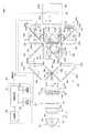
以下、図1等を参照して、本発明の第1実施形態に係るプロジェクターについて説明する。なお、図1において、X、Y、及びZは、3次元直交座標系を構成する3つの座標軸を意味する。ここで、X方向は、照明装置20から投射光学系80までにおける光束の中心軸に相当するシステム光軸SAに常に平行な方向を示す。さらに、Z方向は、常に紙面に垂直な上方向を示し、Y方向は、光路の進行方向又は光路下流側に向かって左手方向を示す。[First Embodiment]
The projector according to the first embodiment of the present invention will be described below with reference to FIG. In FIG. 1, X, Y, and Z mean three coordinate axes that constitute a three-dimensional orthogonal coordinate system. Here, the X direction indicates a direction that is always parallel to the system optical axis SA corresponding to the central axis of the light beam from the
図1に示すプロジェクター100は、照明光を射出する照明装置20と、照明装置20からの照明光を緑赤青の3つの色光に分離する色分離導光部40と、色分離導光部40から射出された3つの色光をそれぞれ変調する光変調部60と、光変調部60から射出された各色の画像光を合成する光合成部70と、光合成部70によって合成された画像光を投射する投射光学系80と、各部の動作を統括的に制御する制御装置90とを備える。これらのうち、照明装置20から光合成部70までの部分は、光学部品用筐体(不図示)の内部に収納されている。なお、本プロジェクター100の場合、照明装置20から投射光学系80までにおける光束の中心軸に相当するシステム光軸SAは、Z軸に垂直なXY平面(紙面に平行な基準面)に平行に2次元的に配置されている。 A
以上のプロジェクター100において、照明装置20は、光源装置10と、凹レンズ14と、第1及び第2のレンズアレイ15,16と、偏光変換装置17と、重畳レンズ18と、調光装置19とを備える。このうち、光源装置10は、照明用の光束を射出する光源であり、例えば高圧水銀ランプ等である発光管11と、発光管11から重畳レンズ18等のある前方に射出された光束を発光管11に戻す副鏡11aと、発光管11から後方に射出された光束を回収して前方に射出させる凹面鏡12とを備える。凹レンズ14は、光源装置10からの光束を平行化する役割を有するが、例えば凹面鏡12が放物面鏡である場合には、省略することもできる。第1のレンズアレイ15は、マトリクス状に配置された複数の要素レンズ15aからなり、レンズ14から射出された光束を要素レンズ15aの区画に対応して分割する。第2のレンズアレイ16は、複数の要素レンズ15aにそれぞれ対応して配置された複数の要素レンズ16aからなり、各要素レンズ15aからの分割光束の発散状態を調整する。偏光変換装置17は、レンズアレイ16から射出された分割光束を第2方向(本実施形態ではY方向)に平行な偏光面を有する直線偏光のみに変換して次段光学系に供給する偏光変換部である。重畳レンズ18は、偏光変換装置17を経た直線偏光としての照明光ILを全体として適宜収束させることにより、被照明領域すなわち光変調部60に設けた各色の液晶ライトバルブ60g,60r,60bに対する重畳照明を可能にする。つまり、両レンズアレイ15,16と重畳レンズ18とを経た照明光ILは、以下に詳述する色分離導光部40を通って、光変調部60に設けられた各色の液晶パネル61g,61r,61bを均一に照明する。 In the
偏光変換装置17は、PBS及びミラーを組み込んだ構造をそれぞれ有する複数のプリズム素子17aと、これらプリズム素子17aの一方の光射出面上にそれぞれ貼り付けられる複数の波長板17bとを備える。各プリズム素子17aは、Z方向に延びる棒状の部材であり、これら複数のプリズム素子17aは、Y方向に配列され、全体としてYZ平面に平行に延びる板状に配置される。偏光変換装置17からは、上述のようにY方向に相当する第2方向の直線偏光である照明光IL(Gp,Rp,Bp)が射出される。 The
調光装置19は、例えば第1のレンズアレイ15と第2のレンズアレイ16との間に配設される。調光装置19は、図2に示すような一対の遮光部19a,19bを有しており、これらの遮光部19a,19bを離間させたり近接させたりすることで開閉動作を行う。これらの可動の遮光部19a,19bにより、照明装置20から射出される照明光ILを照明装置20におけるシステム光軸SAから離れた領域側すなわち外側から優先的に徐々に遮光することができ、照明光量を段階的又は連続的に調整することができる。この際、詳細は後述するが、両遮光部19a,19bの開閉方向は、Z方向であり、偏光変換装置17から射出させる照明光ILの偏光面に垂直な第1方向と一致するものとなっている。調光装置19を開状態とした場合、照明装置20から射出される照明光ILは、照明光の中心軸であるシステム光軸SAを基準として比較的対称的に分布するが、縦のXZ断面における入射角度範囲α1は、横のXY断面における入射角度範囲α2よりも幾分狭くなっている。ここで、入射角度範囲α1と入射角度範囲α2とは、液晶ライトバルブ60g等を照明する際の照明光ILの入射角度範囲を意味するが、結果的に調光装置19の開口OPのZ方向の幅とY方向の幅とにそれぞれ対応するものとなっており、図面では、第2のレンズアレイ16、重畳レンズ18等を省略して簡易に表現している。開状態の調光装置19の開口OPを徐々に閉じてゆくと、縦のXZ断面における入射角度範囲α1が開状態のときよりも相対的に狭くなり、かつ、横のXY断面における入射角度範囲α2に比較してかなり狭くなる。つまり、照明装置20から射出される照明光ILは、調光装置19が開状態であれば、照明光の中心軸であるシステム光軸SAを基準として、これに垂直な第1方向(本実施形態ではZ方向)に関する角度分布が第2方向(本実施形態ではY方向)に関する角度分布よりも小さい状態となる。さらに、調光装置19を開状態から徐々に閉状態にしていくと、第1方向に関する角度分布が当初の開状態の角度分布よりも次第に減少し、第2方向に関する角度分布との差が大きくなる状態となる。これにより、詳細は後述するが、調光装置19による遮光量増加すなわち減光に伴って投射像の静的なコントラストを増加させることができる。なお、動画については、制御装置90は、投射画像に応じて調光装置19を動作させて通過光量を増減させることにより、動的なコントラストも向上させることができる。 The
図1に戻って、色分離導光部40は、クロスダイクロイックミラー21と、ダイクロイックミラー22と、折曲ミラー23a,23bと、第1レンズ31a、31bと、第2レンズ32g,32b,32rとを備える。ここで、クロスダイクロイックミラー21は、第1ダイクロイックミラー21aと、第2ダイクロイックミラー21bとを備える。第1及び第2ダイクロイックミラー21a,21bは互いに直交しており、それらの交差軸21cはZ方向に延びている。第1ダイクロイックミラー21aは、照明光ILに含まれる例えば緑(G)色光及び赤(R)色光を反射し、残りの青(B)色光を透過させる。第2ダイクロイックミラー21bは、青(B)色光を反射し、緑(G)色光及び赤(R)色光を透過させる。ダイクロイックミラー22は、入射した緑(G)色光及び赤(R)色光のうちの例えば緑(G)色光を反射し、残りの赤(R)色光を透過させる。これにより、照明装置20から射出された照明光ILに含まれる緑光Gp、赤光Rp、及び青光Bpは、第1、第2、及び第3光路OP1,OP2,OP3にそれぞれ導かれ、異なる照明対象にそれぞれ入射する。詳細に説明すると、照明装置20からの照明光ILは、クロスダイクロイックミラー21に入射する。クロスダイクロイックミラー21の第1ダイクロイックミラー21aで反射・分岐され、折曲ミラー23a等を経て、ダイクロイックミラー22でさらに反射・分岐された緑光Gpは、液晶ライトバルブ60gの偏光分離素子52gに入射する。さらに、クロスダイクロイックミラー21の第1ダイクロイックミラー21aで反射・分岐され、ダイクロイックミラー22の通過によって分岐された赤光Rpは、液晶ライトバルブ60rの偏光分離素子52rに入射する。クロスダイクロイックミラー21の第2ダイクロイックミラー21bで反射・分岐された青光Bpは、折曲ミラー23b等を経て、液晶ライトバルブ60bの偏光分離素子52bに入射する。 Returning to FIG. 1, the color
なお、第1光路OP1上に配された第1レンズ31aと第2レンズ32gとは、液晶パネル61gに入射する緑光Gpの角度状態を調整するために設けられている。また、第2光路OP2上に配された第1レンズ31aと第2レンズ32rとは、液晶パネル61rに入射する赤光Rpの角度状態を調整するために設けられている。第3光路OP3上に配された第1レンズ31bと第2レンズ32bとは、液晶パネル61bに入射する青光Bpの角度状態を調整するために設けられている。 The
光変調部60は、上記した各色用の3つの光路OP1,OP2,OP3に対応して、3つの液晶ライトバルブ60g,60r,60bを備える。各液晶ライトバルブ60g,60r,60bは、入射した照明光の強度の空間分布を変調する非発光型の光変調装置である。 The
ここで、第1光路OP1に配置されたG色用の液晶ライトバルブ60gは、緑光Gpによって照明される液晶パネル61gと、液晶パネル61gの位相ずれを補正する位相差補償板62gと、液晶ライトバルブ60gでの緑光の入出射を管理する偏光分離素子52gと、偏光分離素子52gの偏光分離特性を補填するクリーンアップ偏光板55gとを備える。このうち、液晶パネル61gは、背面側に反射板を備え、照明光が入射した面から変調された光が射出される反射型の液晶パネルであり、第1ダイクロイックミラー21a及びダイクロイックミラー22で反射された緑光Gpによって均一な面内照度で照明される。液晶パネル61gは、図示による説明を省略するが、透明電極等を有する光透過性基板と、反射画素電極等を有する駆動基板と、光透過性基板及び駆動基板間に密閉封入される液晶層とを備える。偏光分離素子52gは、偏光分離面として射出側パターン層53gを有する。偏光分離素子52gは、構造性複屈折型の光学素子、具体的には光透過性の本体平板上に偏光分離面としての導電材料のグリッドをストライプ状に形成した出射側パターン層53gを設けたワイヤグリッド偏光分離素子である。偏光分離面すなわち射出側パターン層53gは、システム光軸SAに対して垂直な状態からZ軸のまわりに45°回転して傾斜した状態となっている。出射側パターン層53gは、第1方向に沿って非周期であり、第2方向に沿って周期的に繰り返される構造を有する。射出側パターン層53gは、入射した緑光Gpについて、上述の第2方向(この場合、Y方向)の直線偏光を選択的に透過させて液晶パネル61gに導く。液晶パネル61gは、これに入射した緑光Gpを画像信号に応じて、偏光状態を変化させ、偏光分離素子52gに向けて反射する。偏光分離素子52gの射出側パターン層53gは、液晶パネル61gを経て変調された光のうち第1方向(Z方向)に偏光面を有する光のみを選択的に反射する。この際、位相差補償板62gを設けることによって、偏光分離素子52gの射出側における消光比を高めることができ、変調光のコントラストをより向上させることができる。 Here, the G color liquid crystal
液晶ライトバルブ60gにおいて、偏光分離素子52gに入射する照明光としての緑光Gpの偏光面に対応する第2方向(Y方向)が、射出側パターン層53gへの入射面(XY面に平行な面)に対して略平行になっている。つまり、緑光Gpは、そのほとんどがP偏光状態で射出側パターン層53gを効率よく通過する。また、液晶パネル61gから射出され、偏光分離素子52gによって反射される画像光としての緑光Gsは、その偏光面に対応する第1方向(Z方向)が射出側パターン層53gへの入射面(XY面に平行な面)に対して略垂直になっている。つまり、緑光Gsは、液晶パネル61gで変調された光のうち射出側パターン層53gで効率よく反射されるS偏光状態である。 In the liquid crystal
以上の偏光分離素子52gについては、図2に示すように、その主面に沿って、射出側パターン層53gが周期的に形成された周期方向D2と、この周期方向D2に垂直な非周期方向D1とが規定される。ここで、中心軸であるシステム光軸SAから周期方向D2又はY方向に傾いて偏光分離素子52gに入射する緑光Gpは、偏光特性が比較的劣化しないでこれを透過する。これに対応して、液晶パネル61gで反射されて偏光分離素子52gに入射する光のうち画像となる緑光Gsも、偏光特性が比較的劣化しないで反射・射出される。一方、中心軸のシステム光軸SAから非周期方向D1又はZ方向に傾いて偏光分離素子52gに入射する緑光Gpは、これを透過する際に傾きの程度に応じて偏光特性が多少劣化する。これに対応して、液晶パネル61gで反射されて偏光分離素子52gに入射する光のうち画像となる緑光Gsも、反射・射出される際に傾きの程度に応じて偏光特性が多少劣化する。具体的には、偏光分離素子52gはそこを透過又は反射した光が互いに直交する直線偏光となるように構成されているが、システム光軸SAから非周期方向D1に傾いて偏光分離素子52gに入射しそこを透過又は反射した光は、その傾き角度に応じた楕円偏光であり、システム光軸SAから周期方向D2に傾いて偏光分離素子52gに入射しそこを透過又は反射した光は、所望の直線偏光である。 As shown in FIG. 2, the
ここで、偏光分離素子52gに入射する緑光Gpは、調光装置19が図3(A)に示す開状態である場合に、図2からも明らかなように、システム光軸SAを基準としてこれに垂直な第1方向すなわちZ方向に関する角度分布(入射角度範囲α1に相当)が、第1方向(Z方向)に対して垂直な第2方向すなわちY方向に関する角度分布(入射角度範囲α2に相当)よりも小さい状態となる。さらに、調光装置19を図3(A)に示す開状態から図3(B)に示す半遮光状態に変化させた場合、図2からも明らかなように、第1方向すなわちZ方向に関する角度分布が第2方向すなわちY方向に関する角度分布よりもさらに小さい状態となる。つまり、図3(A)に示す開状態では、周期方向D2又はY方向に比較して、非周期方向D1又はZ方向に関して幾分小さな角度分布を有する緑光Gpが偏光分離素子52gに入射するが、図3(B)に示す半遮光状態では、周期方向D2又はY方向に比較して、非周期方向D1又はZ方向に関してかなり小さな角度分布を有する緑光Gpが偏光分離素子52gに入射する。つまり、図3(A)に示す開状態から図3(B)に示す半遮光状態に変化することにより、偏光分離素子52gに入射する緑光Gpは、周期方向D2(Y方向)の角度分布よりも非周期方向D1(Z方向)の角度分布が相対的に減少する。先に説明したように、システム光軸SAから非周期方向D1(Z方向)に傾いて偏光分離素子52gに入射しそこを透過又は反射した光はその傾き角度に応じて楕円偏光となり所望の偏光分離特性が得られないが、調光装置19を図3(A)に示す開状態から図3(B)に示す半遮光状態にして照明光ILの非周期方向D1(Z方向)に関する角度分布を相対的に減少させることにより、偏光分離素子52gでの偏光分離特性が良くなって、液晶ライトバルブ60gのコントラストに関する性能が向上すると考えられる。 Here, the green light Gp incident on the
第2光路OP2に配置された赤色用の液晶ライトバルブ60rは、緑色用の液晶ライトバルブ60gと同様の構造を有している。すなわち、液晶ライトバルブ60rは、赤光Rpによって照明される液晶パネル61rと、液晶パネル61rの位相ずれを補正する位相差補償板62rと、液晶パネル61rへの赤光Rp及び液晶パネル61rからの赤光Rsをその偏光状態に応じて透過又は反射して液晶ライトバルブ60rの赤光Rp,Rsの入出射を管理する偏光分離素子52rと、偏光分離素子52rの偏光分離特性を補填するクリーンアップ偏光板55rとを備える。この液晶パネル61rは背面側に反射板を備え、照明光が入射した面から変調された光が射出される反射型の液晶パネルであり、第1ダイクロイックミラー21aで反射されダイクロイックミラー22を透過した赤光Rpによって均一な面内照度で照明される。偏光分離素子52rは、システム光軸SAに対して傾斜して配置されるとともに偏光分離面として射出側パターン層53rを有する。偏光分離素子52rは、偏光分離素子52gと同じくワイヤグリッド偏光分離素子その他の構造性複屈折型の光学素子であり、入射した赤光Rpについて、上述の第2方向(この場合、Y方向)の直線偏光を選択的に透過させて液晶パネル61rに導く。液晶パネル61rは、これに入射した赤光Rpを画像信号に応じて、偏光状態を変化させ、偏光分離素子52rに向けて反射する。偏光分離素子52rの射出側パターン層53rは、液晶パネル61rを経て変調された光のうち第1方向の直線偏光のみを選択的に反射する。この際、位相差補償板62rを設けることによって、偏光分離素子52rの射出側における消光比を高めることができ、変調光のコントラストを向上させることができる。 The red liquid
液晶ライトバルブ60rにおいて、偏光分離素子52rに入射する照明光としての赤光Rpは、その偏光面に対応する第2方向(Y方向)が射出側パターン層53rへの入射面(XY面に平行な面)に対して全体として略平行になっている。つまり、赤光Rpは、そのほとんどがP偏光状態で射出側パターン層53rを効率よく通過する。また、液晶パネル61rから射出され、偏光分離素子52rによって反射される画像光としての赤光Rsは、その偏光面に対応する第1方向(Z方向)が射出側パターン層53rへの入射面(XY面に平行な面)に対して略垂直になっている。つまり、赤光Rsは、液晶パネル61rで変調された光のうち射出側パターン層53rで効率よく反射されるS偏光状態である。 In the liquid
なお、偏光分離素子52rに入射する赤光Rpは、調光装置19が図3(A)に示す開状態である場合に、システム光軸SAを基準としてこれに垂直な第1方向すなわちZ方向に関する角度分布が第2方向すなわちY方向に関する角度分布よりも小さい状態となる。調光装置19を図3(A)に示す開状態から図3(B)に示す半遮光状態に変化させた場合、第1方向すなわちZ方向に関する角度分布が第2方向すなわちY方向に関する角度分布よりもさらに小さい状態となる。つまり、図3(A)に示す開状態から図3(B)に示す半遮光状態に変化することにより、偏光分離素子52rに入射する赤光Rpは、非周期方向D1(Z方向)の角度分布が周期方向D2(Y方向)の角度分布よりも相対的に減少する。このため、偏光分離素子52gでの説明と同様に赤光Rpについても、図3(B)に示す半遮光状態の方が、図3(A)に示す開状態よりも偏光分離素子52rでの偏光分離特性が良くなって、液晶ライトバルブ60rのコントラストに関する性能が向上すると考えられる。 Note that the red light Rp incident on the
第3光路OP3に配置された青色用の液晶ライトバルブ60bは、緑色用の液晶ライトバルブ60gと同様の構造を有している。すなわち、液晶ライトバルブ60bは、青光Bpによって照明される液晶パネル61bと、液晶パネル61bの位相ずれを補正する位相差補償板62bと、液晶パネル61bへの青光Bp及び液晶パネル61bからの青光Bsをその偏光状態に応じて透過又は反射して液晶ライトバルブ60bの青光Bp,Bsの入出射を管理する偏光分離素子52bと、偏光分離素子52bの偏光分離特性を補填するクリーンアップ偏光板55bとを備える。この液晶パネル61bは背面側に反射板を備え、照明光が入射した面から変調された光が射出される反射型の液晶パネルであり、第2ダイクロイックミラー21bで反射された青光Bpによって均一な面内照度で照明される。偏光分離素子52bは、システム光軸SAに対して傾斜して配置されるとともに偏光分離面として射出側パターン層53bを有する。偏光分離素子52bは、偏光分離素子52gと同じくワイヤグリッド偏光板その他の構造性複屈折型の光学素子であり、入射した青光Bpについて、上述の第2方向(この場合、Y方向)の直線偏光を選択的に透過させて液晶パネル61bに導く。液晶パネル61bは、これに入射した青光Bpを画像信号に応じて、偏光状態を変化させ、偏光分離素子52bに向けて反射する。偏光分離素子52bの射出側パターン層53bは、液晶パネル61bを経て変調された光のうち第1方向の直線偏光のみを選択的に反射する。この際、位相差補償板62bを設けることによって、偏光分離素子52bの射出側における消光比を高めることができ、変調光のコントラストを向上させることができる。 The blue liquid crystal
液晶ライトバルブ60bにおいて、偏光分離素子52bに入射する照明光としての青光Bpは、その偏光面に対応する第2方向(Y方向)が射出側パターン層53bへの入射面(XY面に平行な面)に対して全体として略平行になっている。つまり、青光Bpは、そのほとんどが略P偏光状態で射出側パターン層53bを効率よく通過する。また、液晶パネル61bから射出され、偏光分離素子52bによって反射される画像光としての青光Bsは、その偏光面に対応する第1方向(Z方向)が射出側パターン層53bへの入射面(XY面に平行な面)に対して略垂直になっている。つまり、青光Bsは、液晶パネル61bで変調された光のうち射出側パターン層53bで効率よく反射される略S偏光状態である。 In the liquid crystal
なお、偏光分離素子52bに入射する青光Bpは、調光装置19が図3(A)に示す開状態である場合に、システム光軸SAを基準としてこれに垂直な第1方向すなわちZ方向に関する角度分布が第2方向すなわちY方向に関する角度分布よりも小さい状態となる。調光装置19を図3(A)に示す開状態から図3(B)に示す半遮光状態に変化させた場合、第1方向すなわちZ方向に関する角度分布が第2方向すなわちY方向に関する角度分布よりもさらに小さい状態となる。つまり、図3(A)に示す開状態から図3(B)に示す半遮光状態に変化することにより、偏光分離素子52bに入射する青光Bpは、非周期方向D1(Z方向)の角度分布が周期方向D2(Y方向)の角度分布よりも相対的に減少する。このため、偏光分離素子52gでの説明と同様に青光Bpについても、図3(B)に示す半遮光状態の方が、図3(A)に示す開状態よりも偏光分離素子52bでの偏光分離特性が良くなって、液晶ライトバルブ60bのコントラストに関する性能が向上すると考えられる。 Note that the blue light Bp incident on the
光合成部70は、4つの直角プリズムを貼り合わせた平面視略正方形状をなし、直角プリズム同士を貼り合わせた界面には、合成面として、X字状に交差するとともに交差軸71cがZ方向に延びる一対のダイクロイックミラー71a,71bが形成されている。両ダイクロイックミラー71a,71bは、特性が異なる誘電体多層膜で形成されている。すなわち、一方の第1ダイクロイックミラー71aは赤光LR(赤光Rsに同じ)を反射し、他方の第2ダイクロイックミラー71bは青光LB(青光Bsに同じ)を反射する。この光合成部70は、液晶ライトバルブ60gからの変調後の緑光LG(1/2波長板を経て偏光方向が変わった緑光Gsに同じ)を第1及び第2ダイクロイックミラー71a,71bを透過させることによりX方向に直進させ、液晶ライトバルブ60rからの変調後の赤光LRを第1ダイクロイックミラー71aで反射して光路を折り曲げることによりX方向に射出させ、液晶ライトバルブ60bからの変調後の青光LBを第2ダイクロイックミラー71bで反射して光路を折り曲げることによりX方向に射出させる。光合成部70の光射出側では、各色光LG,LB,LRが重ね合わされて色合成が行われる。なお、光合成部70とG色用の液晶パネル61gとの間には、1/2波長板56が配置されている。この場合、緑光LGをP偏光状態でダイクロイックミラー71a,71bに入射させることができ、光合成部70における各色光LG,LR,LBの合成効率を高めることができ、色ムラの発生を抑えることができる。The
投射光学系80は、光合成部70で合成されたカラーの画像光を、所望の倍率でスクリーン(不図示)上に投射する。つまり、各液晶パネル61g,61r,61bに入力された駆動信号或いは画像信号に対応するカラー動画やカラー静止画は、所望の倍率でスクリーン上に投射される。 The projection
制御装置90は、ビデオ信号等の外部画像信号が入力される画像処理部91と、画像処理部91の出力に基づいて各液晶ライトバルブ60g,60r,60bを駆動するパネル駆動部92と、調光装置19を電気的に駆動する調光装置駆動部93と、これらの回路部分91等の動作を制御する主制御部99とを備える。 The
制御装置90において、画像処理部91は、入力された外部画像信号に対して色補正、歪補正等を含む各種補正を行うことや、外部画像信号に代えて或いは重畳して文字情報等を表示する画像信号を形成することができる。 In the
パネル駆動部92は、画像処理部91から出力された画像処理後の画像信号に基づいて各液晶ライトバルブ60g,60r,60bの状態を調節する駆動信号を発生する。これにより、画像処理部91から入力された画像信号に対応して、液晶ライトバルブ60g,60r,60bにおいて、透過率分布としての画像を形成することができる。 The
調光装置駆動部93は、調光装置19を動作させることにより、両遮光部19a,19bのZ方向の間隔すなわち開口OPのサイズを増減させることができる。 The
主制御部99は、マイクロコンピューターからなり、画像処理部91等を制御するために適宜用意されたプログラムに基づいて動作する。主制御部99は、画像処理部91に対し投射シーンに合わせて照明光量を増減する調光制御を行わせることができる。具体的には、例えばシーンが暗いときには、画像処理部91及び調光装置駆動部93を適宜動作させて調光装置19を比較的閉状態にすることで、コントラストを高めつつ画像をより暗くする。逆に、シーンが明るいときには、画像処理部91及び調光装置駆動部93を適宜動作させて調光装置19を比較的開状態にすることで、コントラストを多少犠牲にしても画像をより明るくする。これにより、動的にも静的にもコントラストを高めた高品位の画像を投射することができる。 The
図3(C)及び3(D)は、図3(A)及び3(B)に示す調光装置19の変形例を示す。図3(C)は開状態を示し、図3(D)は半遮光状態を示す。この場合、調光装置119を構成する一対の遮光部119a,119bのエッジEG,EGは、Y軸方向に平行な直線ではなく、凸の曲線になっている。ここで、非周期方向D1に対応する第1方向(Z方向)のエッジEG,EGの間隔を、調光装置119の開口OPのZ幅とする。本変形例では、開口OPのZ幅が、第2方向(Y方向)の位置によって異なっている。具体的には、開口OPのZ幅は、+Y方向になるほど広がっている。 3 (C) and 3 (D) show a modification of the
以下、調光装置119の開口OPのZ幅を第2方向(Y方向)の位置によって変化させる理由について説明する。図4は、例えば全面黒画像を表示する際の、光路OP1のクリーンアップ偏光板55gの出射側での光漏れの角度分布を説明するものである。液晶ライトバルブ60gが理想的な性能を有していても、クリーンアップ偏光板55gにおいて光路下流側で−Yに向かう傾きを有する光束の光漏れが大きくなる傾向があることが分かる。よって、クリーンアップ偏光板55gにおいて光路下流側で−Yに向かう傾きを有する光束の光漏れを減少させるためには、クリーンアップ偏光板55gにおいて光路下流側で−Yに向かう傾きを有する光束の光量を減少させるように、第1ダイクロイックミラー21a、折曲ミラー23a、及びダイクロイックミラー22での反射による反転も考慮して、本変形例では調光装置119の−Y側で第1方向(Z方向)に関する開口OPの幅を相対的に狭くすればよい。つまり、図3(C)に示すような形状を有する遮光部119a,119bを用いることで、当初から光漏れの角度依存性の少ない照明が可能になり、コントラストの高い画像を投射することができる。さらに、図3(C)に示す遮光部119a,119bを図3(D)に例示するような閉状態に変化させることで、減光に際して光漏れの角度依存性をさらに抑えることができ、遮光量に関わらず投射像のコントラストを極めて高くすることができる。 Hereinafter, the reason why the Z width of the opening OP of the
以上は、G色用の液晶ライトバルブ60gについての説明であったが、R色用の液晶ライトバルブ60rについても同様のことが成り立つ。つまり、液晶ライトバルブ60rが理想的な性能を有していても、全面黒画像を表示する際の光路OP2のクリーンアップ偏光板55rにおいて光路下流側で+Yに向かう傾きを有する光束の光漏れが大きくなる傾向がある。したがって、クリーンアップ偏光板55rにおいて光路下流側で+Yに向かう傾きを有する光束の光量を減少させるように、第1ダイクロイックミラー21a、及び折曲ミラー23aでの反射による反転も考慮して、本変形例では図3(C)に示すような調光装置119を用いることで、光漏れの角度依存性をさらに抑えることができ、調光量に関わらずコントラストの極めて高い画像を投射することができる。 The above is a description of the liquid crystal
なお、B色用の液晶ライトバルブ60bについては、G色用の液晶ライトバルブ60g等と事情が異なる。すなわち、全面黒画像を表示する際の光路OP3のクリーンアップ偏光板55bにおいて光路下流側で−Yに向かう傾きを有する光束の光漏れが大きくなる傾向がある。したがって、クリーンアップ偏光板55bにおいて光路下流側で−Yに向かう傾きを有する光束の光量を減少させるためには、第2ダイクロイックミラー21b、及び折曲ミラー23bでの反射による反転も考慮して、理論上は、図3(C)に示すような調光装置119を構成する遮光部119a,119bをY方向に関して反転させた遮光部を用いることで、光漏れの角度依存性の少ない照明が可能になる。しかしながら、緑赤青で共通の照明装置20を用いていることから、例示の色分離導光部40の構成をとった場合、B色用の液晶ライトバルブ60bについては、光漏れの角度依存性を犠牲にすることになる。ただし、青光については、緑光等に比較して比視感度が低いのでコントラストの劣化が目立たず、G色用の液晶ライトバルブ60g等のコントラストが高ければ、合成されたカラー画像のコントラストも高いものとなる。 The situation of the liquid crystal
図5のグラフは、図3(A)や図3(C)調光装置19,119を用いた調光とコントラストとの関係を説明するグラフである。グラフ中で、印「■」は図3(A)の調光装置19によるコントラストの変化を示し、印「×」は図3(C)の調光装置119によるコントラストの変化を示す。なお、グラフ中で、印「◆」は、後述する第1の比較例によるコントラストの変化を示し、印「△」は、後述する第2の比較例によるコントラストの変化を示す。 The graph of FIG. 5 is a graph for explaining the relationship between light control and contrast using the
図3(E)及び3(F)は、第1の比較例の調光装置を示す。第1の比較例の調光装置4を構成する一対の遮光部4a,4bのエッジEG,EGは、Z方向に平行な直線となっており、両エッジEG,EGのY方向の間隔が変化する。図3(G)及び3(H)は、第2の比較例の調光装置を示す。第2の比較例の調光装置5を構成する遮光部5aのエッジEGは、Y及びZ方向に等方的な円となっており、エッジEGの直径が変化する。 3 (E) and 3 (F) show a light control device of a first comparative example. The edges EG, EG of the pair of
図5のグラフからも明らかなように、図3(C)等に示す調光装置119のコントラストが全体的に最も高く、図3(A)等に示す調光装置19のコントラストも全体的に高い。なお、図3(G)の調光装置5については、隅部分をカットしているためか、遮光に伴って多少コントラストが向上する傾向があるが、図3(E)の調光装置4については、遮光してもコントラストが向上しない。 As is apparent from the graph of FIG. 5, the contrast of the
以上の説明から明らかなように、本実施形態のプロジェクター100によれば、照明装置20が、第1方向(Z方向)に関する角度分布が第2方向(Y方向)に関する角度分布よりも小さい状態の照明光ILを射出する。また、構造性複屈折型の偏光分離素子である偏光分離素子52g,52r,52bが、その非周期方向D1が第1方向(Z方向)に平行になるように配置されている。従って、偏光分離素子52g,52r,52bに入射する照明光IL(Gp,Rp,Bp)は、偏光分離素子52g,52r,52bの偏光分離特性の角度依存性が比較的高い第1方向に関する角度範囲が、偏光分離素子52g,52r,52bの偏光分離特性の角度依存性が比較的低い第2方向に関する角度範囲に比較して相対的に狭くなる。これにより、偏光分離素子52g,52r,52bの偏光分離特性を良好なものとすることができ、偏光分離素子52g,52r,52b等による光漏れを低減できるので、投射画像のコントラストを高めることができる。さらに、調光装置19等を動作させて開状態から半遮光状態に変化させることにより、偏光分離素子52g,52r,52bに入射する照明光ILは、第1方向の角度分布が第2方向の角度分布より相対的に減少するため、液晶ライトバルブ60g,60r,60bのコントラストに関する性能が減光に伴って大きく向上する。 As is clear from the above description, according to the
上記実施形態では、照明装置20において、第1及び第2のレンズアレイ15,16間に調光装置19,119を配置しているが、第2のレンズアレイ16と偏光変換装置17との間に調光装置19,119を配置しても同様の目的を達成することができる。また、偏光変換装置17と重畳レンズ18との間に調光装置19,119を配置しても同様の目的を達成することができる。 In the above-described embodiment, the
また、調光装置19,119の周囲に配置される外枠19d,119dは、図3(A)〜3(D)に示すような矩形の開口を有するものに限らず、円形の開口を有するものとできる。 Moreover, the
また、調光装置19,119は、遮光部19a,19b,119a,119bを固定した固定型の絞りとすることができる。この場合、図3(A)〜3(D)のいずれの状態であっても、Z方向及びY方向に同寸の開口OPを有する場合に比較してコントラストを向上させることができる。Further, the
〔第2実施形態〕
以下、第2実施形態に係るプロジェクターの光学系の構成について説明する。なお、第2実施形態のプロジェクターは、第1実施形態のプロジェクター100を変形したものであり、特に説明しない部分は、第1実施形態と同様である。[Second Embodiment]
Hereinafter, the configuration of the optical system of the projector according to the second embodiment will be described. The projector according to the second embodiment is a modification of the
図6は、第2実施形態に係るプロジェクターの光学系の構成を説明する平面図である。本実施形態のプロジェクター200の場合、照明装置20に調光装置19を設ける代わりに、投射光学系80内に絞り219を設けている。絞り219は、例えば投射光学系80内の瞳位置や光源像の位置に配置される。なお、簡単のため、投射光学系80内のレンズ群については図示を省略している。 FIG. 6 is a plan view illustrating the configuration of the optical system of the projector according to the second embodiment. In the case of the
図7(A)は、絞り219の形状等を説明する図である。絞り219は、一対の遮光部19a,19bを有しており、これらの遮光部19a,19bをZ方向に離間させたり近接させたりすることで開閉動作を行う。絞り219の開閉状態は、画像処理部91等の制御下で動作する絞り駆動部193によって調整される。なお、絞り219の周囲に配置される外枠19dは、矩形の開口を有するものに限らず、円形の開口を有するものとできる。FIG. 7A is a diagram illustrating the shape of the
絞り219を通過する光束は、絞り219をより閉状態とすることにより、システム光軸SAに垂直な第1方向(Z方向)に関する角度分布が相対的に減少する。つまり、各色用の液晶ライトバルブ60g,60r,60bから射出されて投射光学系80によって投射される各色光LG,LB,LRの第1方向(Z方向)に関する角度分布は、遮光にともなって減少し、元の開状態に比較して、液晶ライトバルブ60g,60r,60bのコントラストが向上すると考えられる。この場合、遮光部19a,19bによって形成される開口OPの形状は、第1方向(Z方向)が第2方向(Y方向)よりも短いものに限らず、例えば液晶ライトバルブ60g,60r,60bの視野角特性に合わせたものとでき、減光に伴って投射像のコントラストを向上させることができる。 The luminous flux passing through the
なお、絞り219は、これを構成する遮光部19a,19bを開閉させるような可動型とする必要はなく、遮光部19a,19bを開閉させない固定型の絞りとすることができる。つまり、投射光学系80を通過する光束は、システム光軸SAに垂直な第1方向(Z方向)に関する角度分布がシステム光軸SA及び第1方向(Z方向)に垂直な第2方向(Y方向)に関する角度分布よりも小さいものとなる。この場合、各色用の液晶ライトバルブ60g,60r,60bから射出されて投射光学系80によって投射される各色光LG,LB,LRの角度分布は、第1方向(Z方向)が第2方向(Y方向)よりも小さくなる。このような場合、第1方向及び第2方向に等しい角度分布となっている場合に比較して、投射光学系80から投射される画像のコントラストが向上すると考えられる。 The
本実施形態のプロジェクター200によれば、構造性複屈折型の偏光分離素子である偏光分離素子52gが、その非周期方向D1が第1方向(Z方向)に延びるように配置されている。また、投射光学系80が、絞り219によって第1方向(Z方向)に関する角度分布が第2方向(Y方向)に関する角度分布よりも小さい状態の画像光束を通過させる。従って、偏光分離素子52gを経て投射光学系80に入射した光束は、偏光分離素子52g,52r,52bの偏光分離特性の角度依存性が比較的高い第1方向(Z方向)に関する角度範囲が、偏光分離素子52g,52r,52bの偏光分離特性の角度依存性が比較的低い第2方向(Y方向)に関する角度範囲に比較して相対的に狭くなるように絞り219によって減光される。これにより、全面黒画像を表示する際に、偏光分離素子52gの偏光分離特性の角度依存性による光漏れの影響を低減できるので、投射画像のコントラストを高めることができる。さらに、絞り219等を動作させて開状態から半遮光状態に変化させることにより、投射光学系80を通過する画像光束は、第1方向の角度分布が第2方向の角度分布より相対的に減少するため、投射光学系80から投射される画像のコントラストに関する性能が減光に伴って大きく向上する。 According to the
図7(B)は、図7(A)に示す絞り219の変形例を示す。この場合、絞り319を構成する一対の遮光部119a,119bのエッジEG,EGは、図3(C)の場合と同様に、Y軸方向に平行な直線ではなく、凸の曲線になっている。ここで、非周期方向D1に対応する第1方向(Z方向)のエッジEG,EGの間隔を、調光装置319の開口OPのZ幅とする。開口OPのZ幅が、第2方向(Y方向)の位置によって異なっている。具体的には、図3(C),(D)での説明と同様の理由により、開口OPのZ幅は、+Y方向になるほど広がっており、投射光学系80から投射される画像のコントラストを良好にすることができる。 FIG. 7B illustrates a modification of the
以上実施形態に即して本発明を説明したが、本発明は、上記の実施形態に限られるものではなく、その要旨を逸脱しない範囲において種々の態様において実施することが可能であり、例えば次のような変形も可能である。 Although the present invention has been described based on the above embodiments, the present invention is not limited to the above embodiments, and can be implemented in various modes without departing from the gist thereof. Such modifications are also possible.
すなわち、上記実施形態では、第1光路OP1に緑光Gpを導き、第2光路OP2に赤光Rpを導き、第3光路OP3に青光Bpを導いているが、光路と色の組み合わせは変更可能であり、例えば第1光路OP1に緑光Gpを導き、第2光路OP2に青光Bpを導き、第3光路OP3に赤光Rpを導くことができる。 That is, in the above embodiment, the green light Gp is guided to the first optical path OP1, the red light Rp is guided to the second optical path OP2, and the blue light Bp is guided to the third optical path OP3. However, the combination of the optical path and the color can be changed. For example, the green light Gp can be guided to the first optical path OP1, the blue light Bp can be guided to the second optical path OP2, and the red light Rp can be guided to the third optical path OP3.
また、色分離導光部40における光路OP1,OP2,OP3の分岐方法は、実施形態に例示するものに限らず、様々なものとすることができる。 Further, the method of branching the optical paths OP1, OP2, and OP3 in the color
上記実施形態のプロジェクター100では、液晶ライトバルブ60g,60r,60bの偏光分離素子52g,52r,52bをワイヤグリッド偏光分離素子で構成するとしたが、これらの偏光分離素子52g,52r,52bを立体的な誘電体層を多層積層することによって得られるフォトニック結晶その他の構造性複屈折型の光学素子で構成することもできる。 In the
上記実施形態のプロジェクター100では、調光装置19の遮光部19a,19bによって形成される開口OPを矩形としているが、例えば楕円の開口OPも可能である。この場合も、Y方向の間隔を維持しつつZ方向の間隔を増減させるような開閉によって、コントラストの調整が可能になる。 In the
上記実施形態のプロジェクター100,200では、調光装置19,119,219,319にて常に照明光ILの第1方向に関する角度分布を第2方向に関する角度分布より小さくしていたが、調光装置19は設けずに、第1方向に関する角度分布が第2方向に関する角度分布より小さい照明光を射出する光源装置を採用することできる。また、光源装置だけに限らず、光源装置、凹レンズ14及び第1及び第2レンズアレイの少なくともひとつの形状を適宜選択して第1方向に関する角度分布が第2方向に関する角度分布より小さい照明光を射出する照明装置を採用することができる。なお、このような第1方向に関する角度分布が第2方向に関する角度分布より小さい照明光を射出する照明装置と、調光装置19,119又は絞り219,319とを組み合わせることもできる。In the
上記実施形態のプロジェクター100では、照明装置20においてZ方向を第1方向としたが、Y方向を第1方向とすることもできる。この場合、偏光分離素子52g,52r,52bの非周期方向D1や傾き方向も適宜変更するものとする。 In the
上記実施形態のプロジェクター100では、色分離導光部40に波長板を配置していないが、波長板を配置してS偏光及びP偏光の関係を入れ替え、これに対応して偏光分離素子52g,52r,52bの非周期方向D1や傾き方向も適宜変更することもできる。 In the
上記実施形態のプロジェクター100,200では、照明装置20を、光源装置10、一対のレンズアレイ15,16、偏光変換装置17、重畳レンズ18等で構成したが、レンズアレイ15,16等については省略することができ、光源装置10も、LED等の別光源に置き換えることができる。 In the
上記実施形態では、3つの液晶ライトバルブ60g,60r,60bを用いたプロジェクター100,200の例のみを挙げたが、本発明は、2つの液晶ライトバルブを用いたプロジェクター、或いは、4つ以上の液晶ライトバルブを用いたプロジェクターにも適用可能である。 In the above embodiment, only the examples of the
上記実施形態では、スクリーンを観察する方向から投射を行なうフロントタイプのプロジェクターの例のみを挙げたが、本発明は、スクリーンを観察する方向とは反対側から投射を行なうリアタイプのプロジェクターにも適用可能である。 In the above embodiment, only an example of a front type projector that projects from the direction of observing the screen is given, but the present invention is also applicable to a rear type projector that projects from the side opposite to the direction of observing the screen. Is possible.
10…光源装置、 11…発光管、 12…凹面鏡、 14…凹レンズ、 15,16…第1及び第2のレンズアレイ、 17…偏光変換装置、 18…重畳レンズ、 19…調光装置、 19a,19b…遮光部、 20…照明装置、 21…クロスダイクロイックミラー、 22…ダイクロイックミラー、 40…色分離導光部、 52g,52r,52b…偏光分離素子、 53g,53r,53b…射出側パターン層、 60…光変調部、 60g,60r,60b…液晶ライトバルブ、 61g,61r,61b…液晶パネル、 62g,62r,62b…位相差補償板、 70…光合成部、 71a,71b…ダイクロイックミラー、 80…投射光学系、 90…制御装置、 93…調光装置駆動部、 99…主制御部、 100,200…プロジェクター、 119…調光装置、 119a,119b…遮光部、193…駆動部、 D1…非周期方向、 D2…周期方向、EG,EG…エッジ、 IL…照明光、 Gp,Gs,Rp,Rs,Bp,Bs…色光、 OP…開口、 OP1,OP2,OP3…光路、 SA…システム光軸DESCRIPTION OF
Claims (4)
Translated fromJapanese液晶パネルと、前記照明光の中心軸に対して傾斜して配置される偏光分離面を有する構造性複屈折型の偏光分離素子とを有し、前記照明装置からの前記照明光を変調する光変調装置と、
前記光変調装置によって変調された光を投射する投射光学系と、を備え、
前記照明装置は、前記照明光の中心軸に直交する第1方向に関する角度分布が前記第1方向及び前記照明光の中心軸に直交する第2方向に関する角度分布よりも小さい状態の前記照明光を射出し、
前記構造性複屈折型の偏光分離素子の偏光分離面は、前記第1方向に沿って非周期的であり前記第2方向に沿って周期的に繰り返される構造を有し、
前記照明装置は、前記照明光の角度分布を調節する可動の遮光部を有し、
前記遮光部は、前記第1方向の幅が、前記第2方向において、一端側に向かうほど徐々に広がる開口を有する、
プロジェクター。An illumination device that emits illumination light;
Light that has a liquid crystal panel and a structured birefringent polarization separation element having a polarization separation surface that is disposed to be inclined with respect to the central axis of the illumination light, and modulates the illumination light from the illumination device A modulation device;
A projection optical system for projecting light modulated by the light modulation device,
The illumination device emits the illumination light in a state where an angular distribution with respect to a first direction orthogonal to the central axis of the illumination light is smaller than an angular distribution with respect to the first direction and a second direction orthogonal to the central axis of the illumination light. Inject,
Polarization splitting surface of the polarization separation element of the structural birefringent mayhave a structure that is periodically repeated along the first is along the direction aperiodic said seconddirection,
The illumination device has a movable light-shielding part that adjusts the angular distribution of the illumination light,
The light-shielding portion has an opening that gradually increases in width toward the one end side in the second direction in the first direction .
projector.
液晶パネルと、前記照明光の中心軸に対して傾斜して配置される偏光分離面を有する構造性複屈折型の偏光分離素子とを有し、前記照明装置からの前記照明光を変調する光変調装置と、
前記光変調装置によって変調された光を投射する投射光学系と、を備え、
前記照明装置は、前記照明光の中心軸に直交する第1方向に関する角度分布が前記第1方向及び前記照明光の中心軸に直交する第2方向に関する角度分布よりも小さい状態の前記照明光を射出し、
前記構造性複屈折型の偏光分離素子の偏光分離面は、前記第1方向に沿って非周期的であり前記第2方向に沿って周期的に繰り返される構造を有し、
前記照明装置は、照明光の角度分布を制限する遮光部を有する固定型の絞りを備え、
前記遮光部は、前記第1方向の幅が、前記第2方向において、一端側に向かうほど徐々に広がる開口を有する、
プロジェクター。An illumination device that emits illumination light;
Light that has a liquid crystal panel and a structured birefringent polarization separation element having a polarization separation surface that is disposed to be inclined with respect to the central axis of the illumination light, and modulates the illumination light from the illumination device A modulation device;
A projection optical system for projecting light modulated by the light modulation device,
The illumination device emits the illumination light in a state where an angular distribution with respect to a first direction orthogonal to the central axis of the illumination light is smaller than an angular distribution with respect to the first direction and a second direction orthogonal to the central axis of the illumination light. Inject,
Polarization splitting surface of the polarization separation element of the structural birefringent mayhave a structure that is periodically repeated along the first is along the direction aperiodic said seconddirection,
The illuminating device includes a fixed diaphragm having a light shielding portion that restricts an angular distribution of illumination light ,
The light-shielding portion has an opening that gradually increases in width toward the one end side in the second direction in the first direction .
projector.
前記照明装置から射出された照明光を赤光、緑光、及び青光に分離し、前記緑光を前記光変調装置に導き、前記赤光及び青光を前記別の複数の光変調装置にそれぞれ導く色分離導光部と、
前記光変調装置で変調された緑光と前記別の複数の光変調装置でそれぞれ変調された赤光及び青光とを合成して前記投射光学系に入射させる光合成部とをさらに備える、請求項1または請求項2に記載のプロジェクター。A plurality of light modulation devices different from the light modulation device;
The illumination light emitted from the illumination device is separated into red light, green light, and blue light, the green light is guided to the light modulation device, and the red light and blue light are guided to the plurality of other light modulation devices, respectively. A color separation light guide,
The light combining part which synthesize | combines the green light modulated with the said light modulation apparatus, and the red light and blue light each modulated with said another several light modulation apparatus, and makes it inject into the said projection optical system is further provided. Alternatively, the projector accordingto claim 2 .
液晶パネルと、照明光の中心軸に対して傾斜して配置される偏光分離面を有する構造性複屈折型の偏光分離素子とを有し、前記照明装置からの照明光を変調する光変調装置と、
前記光変調装置によって変調された光を投射する投射光学系と、を備え、
前記構造性複屈折型の偏光分離素子の偏光分離面は、前記照明光の中心軸に直交する第1方向に沿って非周期的であり前記照明光の中心軸及び前記第1方向に直交する第2方向に沿って周期的に繰り返される構造を有し、
前記投射光学系は、前記第1方向に関する角度分布が前記第2方向に関する角度分布よりも小さい状態で画像光を通過させ、
投射する画像光の角度分布を調節する可動の遮光部を有する絞りを備え、
前記遮光部は、前記第1方向の幅が、前記第2方向において、一端側に向かうほど徐々に広がる開口を有する、
プロジェクター。An illumination device that emits illumination light;
A light modulation device having a liquid crystal panel and a structural birefringence type polarization separation element having a polarization separation surface arranged to be inclined with respect to the central axis of the illumination light, and modulating the illumination light from the illumination device When,
A projection optical system for projecting light modulated by the light modulation device,
A polarization separation surface of the structural birefringence type polarization separation element is aperiodic along a first direction orthogonal to the central axis of the illumination light, and is orthogonal to the central axis of the illumination light and the first direction. Having a structure periodically repeated along the second direction;
The projection optical system allows image light to pass through in a state where an angular distribution related to the first direction is smaller than an angular distribution related to the second direction,
A diaphragm having a movable light-shielding portion that adjusts the angular distribution of the image light to be projected;
The light-shielding portion has an opening that gradually increases in width toward the one end side in the second direction in the first direction.
projector.
Priority Applications (4)
| Application Number | Priority Date | Filing Date | Title |
|---|---|---|---|
| JP2010065840AJP5471674B2 (en) | 2010-03-23 | 2010-03-23 | projector |
| US13/040,746US8823885B2 (en) | 2010-03-23 | 2011-03-04 | Projector |
| EP11158979.2AEP2372451B1 (en) | 2010-03-23 | 2011-03-21 | Projector with control of the angular distribution of the illumination light |
| CN2011100701915ACN102200677A (en) | 2010-03-23 | 2011-03-23 | Projector |
Applications Claiming Priority (1)
| Application Number | Priority Date | Filing Date | Title |
|---|---|---|---|
| JP2010065840AJP5471674B2 (en) | 2010-03-23 | 2010-03-23 | projector |
Publications (3)
| Publication Number | Publication Date |
|---|---|
| JP2011197512A JP2011197512A (en) | 2011-10-06 |
| JP2011197512A5 JP2011197512A5 (en) | 2013-01-10 |
| JP5471674B2true JP5471674B2 (en) | 2014-04-16 |
Family
ID=43837921
Family Applications (1)
| Application Number | Title | Priority Date | Filing Date |
|---|---|---|---|
| JP2010065840AExpired - Fee RelatedJP5471674B2 (en) | 2010-03-23 | 2010-03-23 | projector |
Country Status (4)
| Country | Link |
|---|---|
| US (1) | US8823885B2 (en) |
| EP (1) | EP2372451B1 (en) |
| JP (1) | JP5471674B2 (en) |
| CN (1) | CN102200677A (en) |
Cited By (1)
| Publication number | Priority date | Publication date | Assignee | Title |
|---|---|---|---|---|
| US8701857B2 (en) | 2000-02-11 | 2014-04-22 | Cummins-Allison Corp. | System and method for processing currency bills and tickets |
Families Citing this family (8)
| Publication number | Priority date | Publication date | Assignee | Title |
|---|---|---|---|---|
| JP5573197B2 (en)* | 2010-01-27 | 2014-08-20 | セイコーエプソン株式会社 | Reflective LCD projector |
| US9070534B2 (en) | 2012-05-04 | 2015-06-30 | Taiwan Semiconductor Manufacturing Co., Ltd. | Ion beam dimension control for ion implantation process and apparatus, and advanced process control |
| JP2014197041A (en) | 2013-03-29 | 2014-10-16 | 船井電機株式会社 | Projector |
| KR101615239B1 (en)* | 2014-10-06 | 2016-04-25 | 엘지전자 주식회사 | Apparatus for projecting space image |
| JP6898214B2 (en)* | 2017-12-08 | 2021-07-07 | マクセル株式会社 | Headlight device |
| JP7223276B2 (en)* | 2019-06-25 | 2023-02-16 | セイコーエプソン株式会社 | Lighting device and projection display device |
| US12399421B2 (en)* | 2020-04-17 | 2025-08-26 | Sony Group Corporation | Projector |
| CN118244567A (en)* | 2022-12-23 | 2024-06-25 | 华为技术有限公司 | Projection device, display device and transportation tool |
Family Cites Families (29)
| Publication number | Priority date | Publication date | Assignee | Title |
|---|---|---|---|---|
| JPH11281923A (en)* | 1998-03-30 | 1999-10-15 | Mitsubishi Electric Corp | Projection display device |
| US6585378B2 (en)* | 2001-03-20 | 2003-07-01 | Eastman Kodak Company | Digital cinema projector |
| US6511183B2 (en)* | 2001-06-02 | 2003-01-28 | Koninklijke Philips Electronics N.V. | Digital image projector with oriented fixed-polarization-axis polarizing beamsplitter |
| EP1461962A1 (en)* | 2002-01-07 | 2004-09-29 | 3M Innovative Properties Company | Color component aperture stops in projection display system |
| JP2004045672A (en)* | 2002-07-11 | 2004-02-12 | Canon Inc | Polarization separation element and optical system using the same |
| CN100363837C (en) | 2002-10-11 | 2008-01-23 | 精工爱普生株式会社 | Lighting fixtures and projectors |
| JP4254442B2 (en)* | 2002-10-11 | 2009-04-15 | セイコーエプソン株式会社 | Lighting device and projector |
| US7008065B2 (en)* | 2003-01-07 | 2006-03-07 | 3M Innovative Properties Company | Color component aperture stops in projection display system |
| TWI225552B (en)* | 2003-07-29 | 2004-12-21 | Delta Electronics Inc | Reflective polarization valve engine and a projection display using the same |
| JP2007522491A (en) | 2003-12-29 | 2007-08-09 | スペシャライト インコーポレイテッド | Method and apparatus for minimizing skew rays in optical and image projection systems |
| JP2006003384A (en)* | 2004-06-15 | 2006-01-05 | Sony Corp | Polarizing beam splitter and liquid crystal projector device |
| JP2006113282A (en) | 2004-10-14 | 2006-04-27 | Canon Inc | Projection display |
| US7226172B2 (en)* | 2005-01-12 | 2007-06-05 | Colorlink, Inc. | Illumination attenuation system |
| JP2006308787A (en) | 2005-04-27 | 2006-11-09 | Seiko Epson Corp | projector |
| JP4678231B2 (en)* | 2005-05-12 | 2011-04-27 | セイコーエプソン株式会社 | Uniform optical element, illumination device and image display device |
| US8237876B2 (en)* | 2005-05-25 | 2012-08-07 | Kim Leong Tan | Tilted C-plate retarder compensator and display systems incorporating the same |
| JP4798366B2 (en)* | 2005-08-04 | 2011-10-19 | 日本ビクター株式会社 | Reflective liquid crystal display element and projection display device |
| US7643053B2 (en)* | 2005-08-04 | 2010-01-05 | Victor Company Of Japan, Ltd. | Reflective liquid crystal display device and projection display apparatus using the same |
| JP2007072401A (en)* | 2005-09-09 | 2007-03-22 | Victor Co Of Japan Ltd | Projection type image display device |
| EP1764644B1 (en) | 2005-09-09 | 2017-08-30 | Viavi Solutions Inc. | Optimally oriented trim retarders |
| JP4886254B2 (en) | 2005-09-13 | 2012-02-29 | キヤノン株式会社 | Optical system and image projection apparatus |
| JP4661510B2 (en)* | 2005-10-03 | 2011-03-30 | 日本ビクター株式会社 | Projection display device and three-plate liquid crystal projector |
| CN100487563C (en)* | 2006-06-05 | 2009-05-13 | 深圳雅图数字视频技术有限公司 | System for promoting microdisplay optical engine contrast |
| JP2008165066A (en)* | 2006-12-28 | 2008-07-17 | Samsung Electronics Co Ltd | Projection type image projection device |
| US20080158511A1 (en)* | 2006-12-28 | 2008-07-03 | Samsung Electronics Co., Ltd. | Image projecting apparatus |
| JP2008275798A (en) | 2007-04-26 | 2008-11-13 | Victor Co Of Japan Ltd | Projection-type display apparatus |
| JP2009031392A (en)* | 2007-07-25 | 2009-02-12 | Seiko Epson Corp | Wire grid type polarizing element, manufacturing method thereof, liquid crystal device and projection display device |
| JP2010014926A (en)* | 2008-07-03 | 2010-01-21 | Seiko Epson Corp | Projector |
| JP5573197B2 (en)* | 2010-01-27 | 2014-08-20 | セイコーエプソン株式会社 | Reflective LCD projector |
- 2010
- 2010-03-23JPJP2010065840Apatent/JP5471674B2/ennot_activeExpired - Fee Related
- 2011
- 2011-03-04USUS13/040,746patent/US8823885B2/ennot_activeExpired - Fee Related
- 2011-03-21EPEP11158979.2Apatent/EP2372451B1/ennot_activeNot-in-force
- 2011-03-23CNCN2011100701915Apatent/CN102200677A/enactivePending
Cited By (2)
| Publication number | Priority date | Publication date | Assignee | Title |
|---|---|---|---|---|
| US8701857B2 (en) | 2000-02-11 | 2014-04-22 | Cummins-Allison Corp. | System and method for processing currency bills and tickets |
| US9129271B2 (en) | 2000-02-11 | 2015-09-08 | Cummins-Allison Corp. | System and method for processing casino tickets |
Also Published As
| Publication number | Publication date |
|---|---|
| US20110234928A1 (en) | 2011-09-29 |
| US8823885B2 (en) | 2014-09-02 |
| JP2011197512A (en) | 2011-10-06 |
| CN102200677A (en) | 2011-09-28 |
| EP2372451B1 (en) | 2016-11-23 |
| EP2372451A1 (en) | 2011-10-05 |
Similar Documents
| Publication | Publication Date | Title |
|---|---|---|
| JP5471674B2 (en) | projector | |
| CN103210347B (en) | Projection-type image display device | |
| JP5446591B2 (en) | projector | |
| JP5910031B2 (en) | Projection device | |
| JP2014048383A (en) | Projection apparatus | |
| JP4144623B2 (en) | projector | |
| JP6278489B2 (en) | Projection display | |
| WO2015075945A1 (en) | Display device | |
| US8242425B2 (en) | Projector having first and second lamps with an illumination control device for turning on lamp having higher contrast with respect to a light modulation device and method of controlling lighting thereof | |
| JP6263840B2 (en) | projector | |
| JP2011095291A (en) | Projector | |
| JP6436514B2 (en) | Projection display | |
| JP6422141B2 (en) | Projection display apparatus and image display method | |
| JP2005106983A (en) | projector | |
| JP5459056B2 (en) | projector | |
| JP2007264245A (en) | projector | |
| JP2010217652A (en) | Projector | |
| JP2016164665A (en) | Projection device | |
| JP2014095911A (en) | Projector | |
| JP2008134276A (en) | projector | |
| KR20080085581A (en) | Projection Variable Projection System | |
| JP2012198258A (en) | Projector | |
| JP2011197517A (en) | projector | |
| JP2009192669A (en) | projector | |
| JP2008209441A (en) | projector |
Legal Events
| Date | Code | Title | Description |
|---|---|---|---|
| A521 | Request for written amendment filed | Free format text:JAPANESE INTERMEDIATE CODE: A523 Effective date:20121116 | |
| A621 | Written request for application examination | Free format text:JAPANESE INTERMEDIATE CODE: A621 Effective date:20121116 | |
| A977 | Report on retrieval | Free format text:JAPANESE INTERMEDIATE CODE: A971007 Effective date:20130812 | |
| A131 | Notification of reasons for refusal | Free format text:JAPANESE INTERMEDIATE CODE: A131 Effective date:20130827 | |
| A521 | Request for written amendment filed | Free format text:JAPANESE INTERMEDIATE CODE: A523 Effective date:20131025 | |
| TRDD | Decision of grant or rejection written | ||
| A01 | Written decision to grant a patent or to grant a registration (utility model) | Free format text:JAPANESE INTERMEDIATE CODE: A01 Effective date:20140107 | |
| A61 | First payment of annual fees (during grant procedure) | Free format text:JAPANESE INTERMEDIATE CODE: A61 Effective date:20140120 | |
| R150 | Certificate of patent or registration of utility model | Ref document number:5471674 Country of ref document:JP Free format text:JAPANESE INTERMEDIATE CODE: R150 Free format text:JAPANESE INTERMEDIATE CODE: R150 | |
| S531 | Written request for registration of change of domicile | Free format text:JAPANESE INTERMEDIATE CODE: R313531 | |
| R350 | Written notification of registration of transfer | Free format text:JAPANESE INTERMEDIATE CODE: R350 | |
| LAPS | Cancellation because of no payment of annual fees |