JP5469484B2 - Near-field light utilizing head gimbal assembly and information recording / reproducing apparatus including the same - Google Patents
Near-field light utilizing head gimbal assembly and information recording / reproducing apparatus including the sameDownload PDFInfo
- Publication number
- JP5469484B2 JP5469484B2JP2010047187AJP2010047187AJP5469484B2JP 5469484 B2JP5469484 B2JP 5469484B2JP 2010047187 AJP2010047187 AJP 2010047187AJP 2010047187 AJP2010047187 AJP 2010047187AJP 5469484 B2JP5469484 B2JP 5469484B2
- Authority
- JP
- Japan
- Prior art keywords
- laser
- field light
- head gimbal
- gimbal assembly
- slider
- Prior art date
- Legal status (The legal status is an assumption and is not a legal conclusion. Google has not performed a legal analysis and makes no representation as to the accuracy of the status listed.)
- Expired - Fee Related
Links
- 239000000725suspensionSubstances0.000claimsdescription24
- 238000003825pressingMethods0.000claimsdescription16
- 238000005452bendingMethods0.000claimsdescription11
- 239000004033plasticSubstances0.000claimsdescription2
- 229910052751metalInorganic materials0.000description19
- 239000002184metalSubstances0.000description19
- 230000003014reinforcing effectEffects0.000description13
- 239000004065semiconductorSubstances0.000description12
- PCHJSUWPFVWCPO-UHFFFAOYSA-NgoldChemical compound[Au]PCHJSUWPFVWCPO-UHFFFAOYSA-N0.000description5
- 229910052737goldInorganic materials0.000description5
- 239000010931goldSubstances0.000description5
- 230000003287optical effectEffects0.000description5
- 239000000758substrateSubstances0.000description5
- 239000004642PolyimideSubstances0.000description4
- 230000000694effectsEffects0.000description4
- 238000000034methodMethods0.000description4
- 229920001721polyimidePolymers0.000description4
- 239000011347resinSubstances0.000description4
- 229920005989resinPolymers0.000description4
- 238000007667floatingMethods0.000description3
- RYGMFSIKBFXOCR-UHFFFAOYSA-NCopperChemical compound[Cu]RYGMFSIKBFXOCR-UHFFFAOYSA-N0.000description2
- 229910052782aluminiumInorganic materials0.000description2
- XAGFODPZIPBFFR-UHFFFAOYSA-NaluminiumChemical compound[Al]XAGFODPZIPBFFR-UHFFFAOYSA-N0.000description2
- 230000000712assemblyEffects0.000description2
- 238000000429assemblyMethods0.000description2
- 239000011248coating agentSubstances0.000description2
- 238000000576coating methodMethods0.000description2
- 229910052802copperInorganic materials0.000description2
- 239000010949copperSubstances0.000description2
- 238000010586diagramMethods0.000description2
- 230000005381magnetic domainEffects0.000description2
- 230000002787reinforcementEffects0.000description2
- ATJFFYVFTNAWJD-UHFFFAOYSA-NTinChemical compound[Sn]ATJFFYVFTNAWJD-UHFFFAOYSA-N0.000description1
- 239000004020conductorSubstances0.000description1
- 230000003247decreasing effectEffects0.000description1
- 238000009429electrical wiringMethods0.000description1
- 238000005516engineering processMethods0.000description1
- JVPLOXQKFGYFMN-UHFFFAOYSA-Ngold tinChemical compound[Sn].[Au]JVPLOXQKFGYFMN-UHFFFAOYSA-N0.000description1
- 239000000463materialSubstances0.000description1
- 238000012986modificationMethods0.000description1
- 230000004048modificationEffects0.000description1
- 230000002093peripheral effectEffects0.000description1
- 229910000679solderInorganic materials0.000description1
- 238000005728strengtheningMethods0.000description1
Images


Landscapes
- Recording Or Reproducing By Magnetic Means (AREA)
- Adjustment Of The Magnetic Head Position Track Following On Tapes (AREA)
- Supporting Of Heads In Record-Carrier Devices (AREA)
Description
Translated fromJapanese本発明は、近接場光を利用して記録媒体に各種の情報を記録再生する近接場光利用ヘッドジンバルアセンブリ及びそれを備えた情報記録再生装置に関するものである。 The present invention relates to a near-field light utilizing head gimbal assembly that records and reproduces various information on a recording medium using near-field light, and an information recording / reproducing apparatus including the same.
近年、コンピュータ機器におけるハードディスクドライブ等の情報記録再生装置は、より大量かつ高密度情報の記録再生を行いたい等のニーズを受けて、さらなる高密度化が求められている。そのため、隣り合う磁区同士の影響や、熱揺らぎを最小限に抑えるために、保磁力の強いものを記録媒体として採用することが考えられている。そのため、記録媒体に情報を記録することが困難になっていた。 In recent years, an information recording / reproducing apparatus such as a hard disk drive in a computer device has been demanded to have a higher density in response to a need to record and reproduce a larger amount of high-density information. Therefore, in order to minimize the influence of adjacent magnetic domains and thermal fluctuation, it is considered to employ a recording medium having a strong coercive force. Therefore, it has been difficult to record information on the recording medium.
そこで、上述した不具合を解消するために、近接場光を利用して磁区を局所的に加熱して一時的に保磁力を低下させ、その間に記録媒体への書き込みを行う熱アシスト磁気記録方式の情報記録再生装置が考案され開発が進められている。 Therefore, in order to eliminate the above-mentioned problems, a magnetically assisted magnetic recording system in which the magnetic domain is locally heated using near-field light to temporarily reduce the coercive force and during which writing to the recording medium is performed. An information recording / reproducing apparatus has been devised and developed.
熱アシスト磁気記録方式による情報記録再生装置には、近接場光を発生させるための近接場光素子およびそれを駆動させるための光学系が必要となる。これら近接場光素子と光学系は、各種のものが考案されている。 An information recording / reproducing apparatus using the heat-assisted magnetic recording system requires a near-field light element for generating near-field light and an optical system for driving the near-field light element. Various types of near-field light elements and optical systems have been devised.
上記光学系の主要なものとして、光源となる半導体レーザが考えられる。例えば特許文献1および特許文献2に示されるように、この半導体レーザをヘッドを有するスライダに固定する構成が知られている。このような構成においては、光学系を構成する要素部品が少なくなるため、各要素部品間における光損失が少なくなり、よって比較的低損失でレーザ光を近接場光素子に供給することができると考えられている。 As a main component of the optical system, a semiconductor laser serving as a light source can be considered. For example, as shown in Patent Document 1 and
一方、熱アシスト磁気記録方式による情報記録再生装置においては、既存の情報記録再生装置であるハードディスクドライブと同様に、記録素子および再生素子等を記録媒体に対して一定の距離だけ離間させる必要があるため空気浮上スライダ技術を用いる。これは、回転する記録媒体によって生じる空気流によって、記録素子および再生素子等を固定したスライダを空気浮上させるものである。空気流はスライダと記録媒体間に所望の圧力分布を発生させている。スライダを記録媒体から離そうとする正圧とスライダを記録媒体に引き付けようとする負圧と、スライダを機械的に支持しているサスペンションによる押しつけ力の釣り合いで、スライダは所望の状態で浮上する。 On the other hand, in the information recording / reproducing apparatus using the heat-assisted magnetic recording method, it is necessary to separate the recording element and the reproducing element from the recording medium by a certain distance, like the hard disk drive that is an existing information recording / reproducing apparatus. Therefore, air floating slider technology is used. In this method, an air flow generated by a rotating recording medium causes the slider on which the recording element and the reproducing element are fixed to float on the air. The air flow generates a desired pressure distribution between the slider and the recording medium. The slider floats in a desired state by the balance between the positive pressure for separating the slider from the recording medium, the negative pressure for attracting the slider to the recording medium, and the pressing force by the suspension that mechanically supports the slider. .
現在、記録媒体とスライダのすきまは10nm程度もしくはそれ以下となっており、スライダと記録媒体間の圧力分布の設計のみならず、サスペンションの機械的特性の設計も重要となっている。特許文献3や特許文献4のように、サスペンションの適切な箇所に補強部材を付加して所望の押しつけ力や、スライダの浮上安定性を確保する手法が知られている。 Currently, the clearance between the recording medium and the slider is about 10 nm or less, and not only the design of the pressure distribution between the slider and the recording medium, but also the design of the mechanical characteristics of the suspension is important. As disclosed in
一般的に半導体レーザはその固定方法によって寿命が大きく左右されると言われている。特許文献1においては半導体レーザをユニット基板に固定して、ユニット基板をスライダおよびサスペンションに固定している。ユニット基板を用いることで半導体レーザを安定的に固定できるため、半導体レーザの寿命を確保することが出来ると考えられる。しかしながら、ユニット基板と言う別の部材を用意するために、高コスト化しやすいと言う欠点がある。
一方、特許文献2においては、半導体レーザはサスペンションとスライダに挟み込まれるように固定されており、サスペンションは半導体レーザを介してスライダを機械的に支持する構造になっている。前述のユニット基板が必要でないために安価な情報記録再生装置を実現できる可能性があるが、絶えず半導体レーザに応力がかかるため半導体レーザの寿命を縮める欠点があった。In general, it is said that the lifetime of a semiconductor laser is greatly influenced by its fixing method. In Patent Document 1, a semiconductor laser is fixed to a unit substrate, and the unit substrate is fixed to a slider and a suspension. Since the semiconductor laser can be stably fixed by using the unit substrate, it is considered that the life of the semiconductor laser can be secured. However, since another member called a unit substrate is prepared, there is a drawback that it is easy to increase the cost.
On the other hand, in
そこで本発明は、このような事情に考慮してなされたもので、その目的は、光源である半導体レーザの寿命を確保しつつ、安価な近接場光利用ヘッドジンバルアセンブリおよび情報記録再生装置を提供することである。 Accordingly, the present invention has been made in view of such circumstances, and an object of the present invention is to provide an inexpensive near-field light utilizing head gimbal assembly and information recording / reproducing apparatus while ensuring the life of a semiconductor laser as a light source. It is to be.
本発明は、上記目的を達成するために、以下の手段を提供する。
本発明に係る近接場光利用ヘッドジンバルアセンブリは、記録媒体の表面に沿って延設され、フレクシャおよびロードビームを有するサスペンションと、フレクシャの一部を構成し、バネ部とバネ部に接続される剛体部とを備えるフレクシャ舌部と、剛体部上に設けられたレーザと、記録媒体の表面と対向するようにフレクシャ舌部上に固定され、レーザから発生した光束を用いて近接場光を発生するスライダと、ロードビームの先端に設けられ、フレクシャ舌部のレーザが配置された側とは逆側の一部分を押圧する押圧部とを備え、フレクシャ舌部は、押圧部を中心として回動するものであり、剛体部は、押圧部による押圧方向に対して直交する面の撓みを抑制するものであることを特徴とするものである。In order to achieve the above object, the present invention provides the following means.
The near-field light utilizing head gimbal assembly according to the present invention extends along the surface of the recording medium, and forms a suspension having a flexure and a load beam, a part of the flexure, and is connected to the spring portion and the spring portion. A flexure tongue that includes a rigid body, a laser provided on the rigid body, and a flexure tongue that is fixed on the flexure tongue so as to face the surface of the recording medium, and generates near-field light using a light beam generated from the laser. And a pressing portion that is provided at the tip of the load beam and presses a portion of the flexure tongue that is opposite to the side where the laser is disposed, and the flexure tongue rotates around the pressing portion. The rigid body portion is characterized in that it suppresses the bending of the surface orthogonal to the pressing direction by the pressing portion.
また、本発明に係る近接場光利用ヘッドジンバルアセンブリは、剛体部の剛性は前記バネ部の剛性よりも高いことを特徴とするものである。 The near-field light utilizing head gimbal assembly according to the present invention is characterized in that the rigidity of the rigid part is higher than the rigidity of the spring part.
また、本発明に係る近接場光利用ヘッドジンバルアセンブリは、剛体部の剛性はレーザの剛性よりも高いことを特徴とするものである。 The near-field light utilizing head gimbal assembly according to the present invention is characterized in that the rigidity of the rigid portion is higher than the rigidity of the laser.
本発明に係る近接場光利用ヘッドジンバルアセンブリにおいては、記録媒体のうねりに対してジンバル機構が動作するが、この際剛体部はたわまないので、剛体部上に固定されたレーザに曲げ応力がかかることがない。よって、レーザを安定的に固定することができ、ひいてはレーザの長寿命化を図ることが出来る。 In the near-field light utilizing head gimbal assembly according to the present invention, the gimbal mechanism operates against the waviness of the recording medium. However, since the rigid body portion does not bend at this time, the bending stress is applied to the laser fixed on the rigid body portion. Will not take. Therefore, the laser can be stably fixed, and the life of the laser can be extended.
ここで特許文献3においては、ロードビーム(ロードアーム)の輪郭に曲げ加工による補強部を設けているが、ジンバル機構とは異なる部位であり、本発明と同様な効果を実現することはできない。また、スライダを固定するサスペンション舌部(スライダ保持部)は補強部(段差部)を設けてはいるが、ヘッドジンバルアセンブリにレーザを搭載することを想定していない上、段差部のためにスライダの一部のみでスライダを保持せざるを得ず、レーザに曲げ応力がかかってしまう。よって、本発明と同様な効果を実現することはできない。 Here, in
また特許文献4においては、サスペンション舌部(サスペンションタング部)に補強部(強化部材)を設けてはいるが、ヘッドジンバルアセンブリにレーザを搭載することを想定していない上、サスペンション舌部全体に補強部を設けており、レーザに曲げ応力がかかることを防止しつつシンバル機構を動作させることを妨げている。よって、本発明と同様な効果を実現することはできない。 In
また、本発明に係る近接場光利用ヘッドジンバルアセンブリは、補強部がフレクシャ舌部の一部を塑性変形させることで形成されていることを特徴とするものである。 The near-field light utilizing head gimbal assembly according to the present invention is characterized in that the reinforcing portion is formed by plastic deformation of a part of the flexure tongue.
本発明に係る近接場光利用ヘッドジンバルアセンブリにおいては、剛体部を所定の剛性とするために別途部材を用意する必要がなく、これを備えるヘッドジンバルアセンブリを安価にすることができる。 In the near-field light utilizing head gimbal assembly according to the present invention, it is not necessary to prepare a separate member in order to make the rigid body portion have a predetermined rigidity, and the head gimbal assembly including this can be made inexpensive.
また、本発明に係る近接場光利用ヘッドジンバルアセンブリは、補強部がレーザを位置決めするレーザガイドであることを特徴とするものである。 The near-field light utilizing head gimbal assembly according to the present invention is characterized in that the reinforcing portion is a laser guide for positioning the laser.
本発明に係る近接場光利用ヘッドジンバルアセンブリにおいては、レーザガイドがレーザを位置決めすることで、容易に組立をおこなうことができる。また、レーザガイドが補強部を兼ねているため、別途部材を用意する必要がなく、これを備えるヘッドジンバルアセンブリを安価にすることができる。 In the near-field light utilizing head gimbal assembly according to the present invention, the laser guide positions the laser so that the assembly can be easily performed. Further, since the laser guide also serves as the reinforcing portion, it is not necessary to prepare a separate member, and the head gimbal assembly including this can be made inexpensive.
また、本発明に係る情報記録再生装置は、上記本発明の近接場光利用ヘッドジンバルアセンブリと、前記記録媒体と、を有するものである。 An information recording / reproducing apparatus according to the present invention includes the near-field light utilizing head gimbal assembly of the present invention and the recording medium.
本発明に係る情報記録再生装置においては、本発明の近接場光利用ヘッドジンバルアセンブリを備えているので、長寿命で安価なものとすることかできる。 Since the information recording / reproducing apparatus according to the present invention includes the near-field light utilizing head gimbal assembly of the present invention, it can be long-lived and inexpensive.
本発明に係る近接場光利用ヘッドジンバルアセンブリによれば、光源である半導体レーザの寿命を確保しつつ、安価な近接場光利用ヘッドジンバルアセンブリおよび情報記録再生装置を提供することができる。 According to the near-field light utilizing head gimbal assembly according to the present invention, it is possible to provide an inexpensive near-field light utilizing head gimbal assembly and information recording / reproducing apparatus while ensuring the life of the semiconductor laser as the light source.
(第1実施形態)
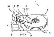
以下、本発明に係る第1実施形態を、図1から図5を参照して説明する。図1は、本実施形態に係る情報記録再生装置1を示す構成図である。なお、本実施形態の情報記録再生装置1は、磁気記録層を有する記録媒体Dに対して、熱アシスト磁気記録方式で書き込みを行う装置である。(First embodiment)
A first embodiment according to the present invention will be described below with reference to FIGS. FIG. 1 is a configuration diagram showing an information recording / reproducing apparatus 1 according to the present embodiment. In addition, the information recording / reproducing apparatus 1 of this embodiment is an apparatus which writes with respect to the recording medium D which has a magnetic-recording layer with a heat-assisted magnetic recording system.
図1に示すように本実施形態の情報記録再生装置1において、スライダ2が固定されたサスペンション3が、キャリッジ11に固定されている。スライダ2とサスペンション3を合わせて、ヘッドジンバルアセンブリ12(近接場光利用ヘッドジンバルアセンブリ)と呼ぶ。円盤状の記録媒体Dはスピンドルモータ7によって所定の方向に回転する。キャリッジ11はピボット10を中心に回転可能になっており、制御部5からの制御信号によって制御されるアクチュエータ6によって回転し、スライダ2を記録媒体D表面の所定の位置に配置することができる。ハウジング9はアルミニウムなどから成る箱状(図1では説明を分かりやすくするため、ハウジング9の周囲を取り囲む周壁を省略している)のものであり、上記の部品をその内部に格納している。スピンドルモータ7はハウジング9の底面に固定されている。スライダ2は記録媒体Dに向けて磁場を発生させる記録素子(図示略)と、近接場光を発生する導光部(図示略)と、記録媒体Dに記録された情報を再生する再生素子(図示略)を有している。記録素子と再生素子は、サスペンション3およびキャリッジ11に沿って敷設されたフレキシブル配線13、キャリッジ11側面に設けられたターミナル14およびフラットケーブル4を介して制御部5に接続されている。 As shown in FIG. 1, in the information recording / reproducing apparatus 1 of this embodiment, a
記録媒体Dは1枚でも良いが、図1に示すように複数枚設けても良い。記録媒体Dの枚数が増えれば、ヘッドジンバルアセンブリ12の個数も増加する。図1では記録媒体Dの片面側のみにヘッドジンバルアセンブリ12が設けられている構成を示しているが、両面に設けても良い。よって、ヘッドジンバルアセンブリ12の個数は、最大で記録媒体Dの枚数の倍になる。これにより、情報記録再生装置1台当たりの記録容量の増加を図ることができる。 One recording medium D may be provided, but a plurality of recording media may be provided as shown in FIG. As the number of recording media D increases, the number of
図2は第1実施形態に係るヘッドジンバルアセンブリ12の拡大図である。サスペンション3は、ステンレス薄板を材料とするベースプレート201、ヒンジ202、ロードビーム203、フレクシャ204からなる。ベースプレート201は、その一部に設けられた取り付け穴201aにより、キャリッジ11に固定されている。ヒンジ202はベースプレート201とロードビーム203を接続している。ヒンジ202はベースプレート201とロードビーム203よりも薄くなっており、ヒンジ202を中心としてサスペンション3がたわむようになっている。フレクシャ204はロードビーム203、ヒンジ202に固定された細長い部材であり、ロードビーム203やベースプレート201よりも薄くなっており、たわみやすく出来ている。フレクシャ204の先端には略直方体形状のスライダ2が固定されている。 FIG. 2 is an enlarged view of the
スライダ2の表面のうちフレクシャ204に固定された面の反対面は、記録媒体Dに対向する面である。この面は回転する記録媒体Dによって生じた空気流の粘性から、スライダ2が浮上するための圧力を発生させる面であり、ABS(Air Bearing Surface)と呼ばれている。ABS上には図示を略した凹凸形状が設けられており、スライダ2と記録媒体D間に所望の圧力分布を発生させている。スライダ2を記録媒体Dから離そうとする正圧とスライダ2を記録媒体Dに引き付けようとする負圧と、サスペンション3による押しつけ力の釣り合いで、スライダ2は所望の状態で浮上している。記録媒体Dとスライダ2のすきまの最低値は10nm程度もしくはそれ以下となっている。サスペンション3による押しつけ力は主にヒンジ202の弾性により発生している。また、記録媒体D表面のうねりに対して、ヒンジ202およびフレクシャ204がたわむことで、所望の浮上状態を維持することが出来る。 The surface opposite to the surface fixed to the
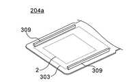
フレクシャ204上にはフレキシブル配線13が設けられている。フレクシャ204は略コ字状の開口部を有しており、この開口部に囲まれて舌状となったパッド部204a上に後述のレーザ303等を挟み込んでスライダ2が固定されている。スライダ2の端部のうち、サスペンション3の根本側(キャリッジ11側)は流入端と呼ばれている。その反対のサスペンション3の先端側は、スライダ2の流出端と呼ばれている。これらは、前述の記録媒体Dによる空気流の方向に基づいて名付けられている。サスペンション3の根本側から延設されたフレキシブル配線13は途中から2本に分岐し、前述の開口部およびスライダ2の両側を回り込むように、スライダ2の流出端側に接続されている。
図3は第1実施形態に係るパッド部204a近傍の拡大図である。図4は図3のA−A’断面である。フレキシブル配線13はベースフィルム301と、それに載る6本の金属配線302からなる。ベースフィルム301はポリイミド等の樹脂からなる。金属配線302は銅からなり、表面が金メッキされている。ベースフィルム301は金属配線302とフレクシャ204とを絶縁している。また、図示はしていないが金属配線302の一部は保護のためにポリイミド等の樹脂で覆われている。6本の金属配線302のうち4本はスライダ2に設けられた記録素子(図示略)および再生素子(図示略)にそれぞれ2本ずつ接続されている。ただし、金属配線302の本数は6本に限られるものではなく、必要に応じて増減することができる。 FIG. 3 is an enlarged view of the vicinity of the
また、パッド部204a上には平面視コの字状のレーザガイド304が配置されている。レーザガイド304はベースフィルム301と同材料、同厚となっている。そのためレーザガイド304とベースフィルム301は同時に形成することができる。レーザ303は平面視コの字状のレーザガイド304にはまりこむようになっており、位置決めが容易になっている。レーザ303は端面発光レーザであるため、その側面からレーザ光が出射する。レーザガイド304はレーザ303側面からのレーザ光出射を妨げないようになっている。レーザ303の厚さはレーザガイド304と等しい。スライダ2はベースフィルム301の一部とレーザ303およびレーザガイド304に載るように固定される。ベースフィルム301の端面のうち、レーザ303に対向する面は、レーザ303からの出射光の光軸方向に対して45度傾斜した斜平面になっており、この斜平面に金属被膜することでミラー面301aとなっている。被膜の金属はアルミニウムや金を用いる。よって、スライダ2とパッド部204aに挟まれるように設置されたレーザ303から出射した光は、ミラー面301aにて90度曲げられて、スライダ2の内部に設けられた近接場光素子(図示略)を有する導光部306に導入される。 In addition, a
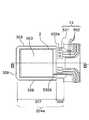
レーザ303はパッド部204aと接する面にカソード電極303aを有し、スライダ2に接する面にアノード電極303bを有する。また、スライダ2はアノード電極303bに接する面に電極2a(スライダ側導電性膜)を有する。電極2aはその一部がスライダ2の側面に突出部2bを有している。突出部2bと6本の金属配線302のうち磁極および再生素子に接続されていない1本の電気配線302aとは、ボール305によるボールボンディングにより電気的に接続されている。6本の金属配線302のうち残る1本の電気配線302bはベースフィルム301上から延設されてパッド部204aに接触している。カソード電極303aおよびアノード電極303bは金などの金属からなっている。また電極2aも導電性の材料からなっており、例えばスズを用いるとアノード電極303bと金スズ接合が可能となり都合が良い。ボール305は金や半田などの金属からなっている。よって、制御部5からの電気信号は電気配線302a、ボール305、電極2a、アノード電極303bを介して、および電気配線302b、パッド部204a、カソード電極303aを介して、レーザ303を駆動する。レーザ303からの光は導光部306に導入され、近接場光となってディスクDの微小領域を加熱することで、熱アシスト磁気記録を実現する。 The
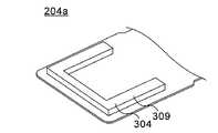
パッド部204aは剛体部307とバネ部308からなっている。パッド部204aはバネ部308でフレクシャ204のその他の部位と接続されている。剛体部307は、ディンプル203aによる押圧方向に対して直交する面の撓みを抑制するものである。図5に示すように剛体部307の輪郭線上には、剛体部307の一部を構成する補強部309が設けられている。これはパッド部204aの一部をバッド部204a面に垂直になるように曲げ加工することで形成される。ロードビーム203のスライダ2側の先端には半球状のディンプル203a(押圧部)が設けられている。ディンプル203aの頂点は剛体部307に接触している。前述のように、サスペンション3によるスライダ2への押しつけ力は主にヒンジ202の弾性により発生しているが、その押しつけ力はディンプル203aと剛体部307の接触を介して伝えられている。また、ディンプル203aの頂点を中心に、パッド部204aおよびスライダ2が回動できるようになっている。つまり、ディンプル203aとパッド部204aによりジンバル機構を構成している。さらに前述のように、記録媒体D表面のうねりに対して、フレクシャ204がたわむことで、スライダ2は所望の浮上状態を維持することが出来るが、この時、補強部309のためにパッド部204aのうち剛体部307はたわむことがなく、バネ部308のみがたわむ。レーザ303はパッド部204aのうち、剛体部307に固定されている。 The
ここまで補強部309は図5に示すように、パッド部204aの一部を曲げ加工することで形成されているが、剛体部307の剛性を確保するものであればどのような形状でも良い。例えば図6に示すように、パッド部204aの一部をリブ状に押し出し加工したものを補強部309としても良い。また、図7に示すようにレーザガイド304を補強部309として用いても良い。 Up to this point, the reinforcing
本実施の形態によって、記録媒体Dのうねりに対して剛体部307はたわまないので、剛体部307上に固定されたレーザ303に曲げ応力がかかることがない。よって、レーザ303を安定的に固定することができ、ひいてはレーザ303の長寿命化を図ることが出来る。また、補強部309のため、剛体部307の剛性を確保するために別途部材を用意する必要がなく、これを備えるヘッドジンバルアセンブリ12および情報記録再生装置1を安価にすることができる。 According to the present embodiment, since the
(第2実施形態)
以下、本発明に係る第2実施形態を、図8と図9を参照して説明する。第1実施形態と同一箇所については同一符号を付して詳細な説明を省略する。本実施形態が第1実施形態と異なる点は、レーザが傾斜面を有し、よってベースフィルム側面に反射面を設けなくて良い点である。(Second Embodiment)
Hereinafter, a second embodiment of the present invention will be described with reference to FIGS. The same parts as those in the first embodiment are denoted by the same reference numerals, and detailed description thereof is omitted. The difference between this embodiment and the first embodiment is that the laser has an inclined surface, and thus it is not necessary to provide a reflecting surface on the side surface of the base film.
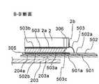
図8は第2実施形態に係るパッド部204a近傍の拡大図である。図9は図5のB−B’断面である。フレキシブル配線13はベースフィルム501と、それに載る6本の金属配線502からなる。ベースフィルム501はポリイミド等の樹脂からなる。金属配線502は銅からなり、表面が金メッキされている。ベースフィルム501は金属配線502とフレクシャ204とを絶縁している。また、図示はしていないが金属配線502の一部は保護のためにポリイミド等の樹脂で覆われている。6本の金属配線502のうち4本はスライダ2に設けられた記録素子(図示略)および再生素子(図示略)にそれぞれ2本ずつ接続されている。 FIG. 8 is an enlarged view of the vicinity of the
ベースフィルム501はスライダ2の平面サイズと略同サイズで剛体部307上にまで延設された延設部501aを有している。6本の金属配線502のうち磁極および再生素子に接続されていない1本の電気配線502bは延設部501a上にまで延設されてその先端はスライダ2の平面サイズと略同サイズの電極となっている。延設部501a上に載る電気配線502b上にはレーザ503が配置されている。スライダ2はレーザ503に載るように固定される。レーザ503からの光はスライダ2方向に出射し、スライダ2の内部に設けられた近接場光素子(図示略)を有する導光部306に導入される。 The
電極2aの突出部2bと6本の金属配線502のうち磁極および再生素子に接続されていない残り1本の電気配線502aとは、ワイヤ503によるワイヤボンディングにより電気的に接続されている。よって、制御部5からの電気信号は電気配線502a、ワイヤ503、電極2a、アノード電極503bを介して、および電気配線502b、カソード電極503aを介して、レーザ503を駆動する。レーザ503からの光は導光部306に導入され、近接場光となってディスクDの微小領域を加熱することで、熱アシスト磁気記録を実現する。 The protruding
本実施の形態によって、第1実施形態と同様の効果を実現することか出来る。つまり、記録媒体Dのうねりに対して剛体部307はたわまないので、剛体部307上に固定されたレーザ303に曲げ応力がかかることがない。よって、レーザ303を安定的に固定することができ、ひいてはレーザ303の長寿命化を図ることが出来る。また、折り曲げ部309のため、剛体部307の剛性を確保に別途部材を用意する必要がなく、これを備えるヘッドジンバルアセンブリ12および情報記録再生装置1を安価にすることができる。 According to the present embodiment, the same effect as that of the first embodiment can be realized. That is, since the
また、レーザ503が傾斜面503cを有しているため、容易にレーザ503と導光部306との位置合わせが可能となり、結果低コストにヘッドジンバルアセンブリ12および情報記録再生装置1を製造することができる。 In addition, since the
なお、本発明の技術範囲は、上述した実施形態に限定されるものではなく、本発明の趣旨を逸脱しない範囲において、上述した実施形態に種々の変更を加えたものを含む。すなわち、上述した実施形態で挙げた構成等はほんの一例に過ぎず、適宜変更が可能である。また、上述した各実施形態を適宜組み合わせて採用することも可能である。 It should be noted that the technical scope of the present invention is not limited to the above-described embodiments, and includes those in which various modifications are made to the above-described embodiments without departing from the spirit of the present invention. In other words, the configuration described in the above-described embodiment is merely an example, and can be changed as appropriate. Moreover, it is also possible to employ | adopt combining each embodiment mentioned above suitably.
D記録媒体 1情報記録再生装置 2スライダ 2a電極 3サスペンション 11キャリッジ 12ヘッドジンバルアセンブリ 13フレキシブル配線 204フレクシャ 204aパッド部 301aミラー面 302電気配線 303レーザ 303aカソード電極 303bアノード電極 306導光部 307剛体部 308バネ部 309補強部 503レーザD recording medium 1 information recording / reproducing
Claims (6)
Translated fromJapanese前記フレクシャの一部を構成し、バネ部と前記バネ部に接続される剛体部とを備えるフレクシャ舌部と、
前記剛体部上に設けられたレーザと、
前記記録媒体の表面と対向するように前記フレクシャ舌部上に固定され、前記レーザから発生した光束を用いて近接場光を発生するスライダと、
前記ロードビームの先端に設けられ、前記フレクシャ舌部の前記レーザが配置された側とは逆側の一部分を押圧する押圧部とを備え、
前記フレクシャ舌部は、前記押圧部を中心として回動するものであり、
前記剛体部は、前記押圧部による押圧方向に対して直交する面の撓みを抑制するものであることを特徴とする近接場光利用ヘッドジンバルアセンブリ。A suspension extending along the surface of the recording medium and having a flexure and a load beam;
A flexure tongue that comprises part of the flexure and comprises a spring portion and a rigid portion connected to the spring portion;
A laser provided on the rigid body;
A slider that is fixed on the flexure tongue so as to face the surface of the recording medium and generates near-field light using a light beam generated from the laser;
A pressing portion that is provided at a tip of the load beam and presses a portion of the flexure tongue that is opposite to the side where the laser is disposed;
The flexure tongue portion rotates around the pressing portion,
The near-field light utilizing head gimbal assembly, wherein the rigid body portion suppresses bending of a surface orthogonal to a pressing direction by the pressing portion.
Priority Applications (1)
| Application Number | Priority Date | Filing Date | Title |
|---|---|---|---|
| JP2010047187AJP5469484B2 (en) | 2010-03-03 | 2010-03-03 | Near-field light utilizing head gimbal assembly and information recording / reproducing apparatus including the same |
Applications Claiming Priority (1)
| Application Number | Priority Date | Filing Date | Title |
|---|---|---|---|
| JP2010047187AJP5469484B2 (en) | 2010-03-03 | 2010-03-03 | Near-field light utilizing head gimbal assembly and information recording / reproducing apparatus including the same |
Publications (2)
| Publication Number | Publication Date |
|---|---|
| JP2011181159A JP2011181159A (en) | 2011-09-15 |
| JP5469484B2true JP5469484B2 (en) | 2014-04-16 |
Family
ID=44692512
Family Applications (1)
| Application Number | Title | Priority Date | Filing Date |
|---|---|---|---|
| JP2010047187AExpired - Fee RelatedJP5469484B2 (en) | 2010-03-03 | 2010-03-03 | Near-field light utilizing head gimbal assembly and information recording / reproducing apparatus including the same |
Country Status (1)
| Country | Link |
|---|---|
| JP (1) | JP5469484B2 (en) |
Cited By (5)
| Publication number | Priority date | Publication date | Assignee | Title |
|---|---|---|---|---|
| US10377098B2 (en) | 2011-07-07 | 2019-08-13 | Automated Packaging Systems, Inc. | Air cushion inflation machine |
| US10391733B2 (en) | 2004-06-01 | 2019-08-27 | Automated Packaging Systems, Inc. | Method for making fluid filled units |
| US10618243B2 (en) | 2007-10-31 | 2020-04-14 | Automated Packaging Systems, Llc | Web and method for making fluid filled units |
| US10647460B2 (en) | 2013-03-15 | 2020-05-12 | Automated Packaging Systems, Llc | On-demand inflatable packaging |
| US10730260B2 (en) | 2004-06-01 | 2020-08-04 | Automated Packaging Systems, Llc | Web and method for making fluid filled units |
- 2010
- 2010-03-03JPJP2010047187Apatent/JP5469484B2/ennot_activeExpired - Fee Related
Cited By (6)
| Publication number | Priority date | Publication date | Assignee | Title |
|---|---|---|---|---|
| US10391733B2 (en) | 2004-06-01 | 2019-08-27 | Automated Packaging Systems, Inc. | Method for making fluid filled units |
| US10730260B2 (en) | 2004-06-01 | 2020-08-04 | Automated Packaging Systems, Llc | Web and method for making fluid filled units |
| US10618243B2 (en) | 2007-10-31 | 2020-04-14 | Automated Packaging Systems, Llc | Web and method for making fluid filled units |
| US10377098B2 (en) | 2011-07-07 | 2019-08-13 | Automated Packaging Systems, Inc. | Air cushion inflation machine |
| US10647460B2 (en) | 2013-03-15 | 2020-05-12 | Automated Packaging Systems, Llc | On-demand inflatable packaging |
| US11572225B2 (en) | 2013-03-15 | 2023-02-07 | Automated Packaging Systems, Llc | On-demand inflatable packaging |
Also Published As
| Publication number | Publication date |
|---|---|
| JP2011181159A (en) | 2011-09-15 |
Similar Documents
| Publication | Publication Date | Title |
|---|---|---|
| US8179745B2 (en) | Head gimbal assembly and disk drive | |
| US6404706B1 (en) | Laser mounting for a thermally assisted GMR head | |
| US8593765B2 (en) | Head gimbal assembly and disk drive with a piezoelectric element | |
| US11056137B1 (en) | Load beam side rail shock contact feature | |
| JP2007272984A (en) | Disk drive device and head assembly used therefor | |
| US8184506B2 (en) | Near-field optical head with inclined magnetic poles and information recording/reproducing device | |
| US8599654B2 (en) | Head gimbal assembly using near-field light and information recording and reproducing apparatus including the same | |
| JP5469484B2 (en) | Near-field light utilizing head gimbal assembly and information recording / reproducing apparatus including the same | |
| US8467276B2 (en) | Thermally-assisted magnetic recording head having photoelectric wiring lines integrally formed on waveguide | |
| JP2001057039A (en) | Head suspension, head gimbals assembly and actuator | |
| GB2549920A (en) | Laser-integrated head gimbal assembly having contact protection | |
| US9013967B1 (en) | Heat-dissipating stepped slider for a heat-assisted magnetic recording head | |
| US11973310B2 (en) | Light source unit and thermally-assisted magnetic head | |
| US11227630B2 (en) | Swage plate assembly with swage boss insert | |
| US20140098652A1 (en) | Side mounted laser diode on a thermal assisted magnetic recording head assembly with integrated microactuator | |
| US20220139421A1 (en) | Restriction of suspension dimple contact point | |
| US7859796B2 (en) | Disk drive and arm coil support assembly | |
| JP5592121B2 (en) | Near-field light utilizing head gimbal assembly and information recording / reproducing apparatus including the same | |
| JP5355248B2 (en) | Near-field light utilizing head gimbal assembly and information recording / reproducing apparatus including the same | |
| US12400679B1 (en) | Thermally assisted magnetic head, head gimbal assembly, and hard disk drive | |
| JP5294961B2 (en) | Thermally assisted magnetic recording head gimbal assembly and information recording / reproducing apparatus including the same | |
| JP5596997B2 (en) | Head gimbal assembly | |
| CN120356492A (en) | Suspension flexure forming a universal gap | |
| JP2025086124A (en) | Disk device | |
| JP2025056701A (en) | Coating of hard disk drive sliders for mechanical improvement of suspension |
Legal Events
| Date | Code | Title | Description |
|---|---|---|---|
| A621 | Written request for application examination | Free format text:JAPANESE INTERMEDIATE CODE: A621 Effective date:20130116 | |
| A977 | Report on retrieval | Free format text:JAPANESE INTERMEDIATE CODE: A971007 Effective date:20140123 | |
| TRDD | Decision of grant or rejection written | ||
| A01 | Written decision to grant a patent or to grant a registration (utility model) | Free format text:JAPANESE INTERMEDIATE CODE: A01 Effective date:20140128 | |
| A61 | First payment of annual fees (during grant procedure) | Free format text:JAPANESE INTERMEDIATE CODE: A61 Effective date:20140131 | |
| R150 | Certificate of patent or registration of utility model | Ref document number:5469484 Country of ref document:JP Free format text:JAPANESE INTERMEDIATE CODE: R150 Free format text:JAPANESE INTERMEDIATE CODE: R150 | |
| R250 | Receipt of annual fees | Free format text:JAPANESE INTERMEDIATE CODE: R250 | |
| R250 | Receipt of annual fees | Free format text:JAPANESE INTERMEDIATE CODE: R250 | |
| LAPS | Cancellation because of no payment of annual fees |