Movatterモバイル変換


[0]ホーム

URL:


JP5469346B2 - Writing instrument - Google Patents

Writing instrument
Download PDF

Info

Publication number
JP5469346B2
JP5469346B2JP2009018274AJP2009018274AJP5469346B2JP 5469346 B2JP5469346 B2JP 5469346B2JP 2009018274 AJP2009018274 AJP 2009018274AJP 2009018274 AJP2009018274 AJP 2009018274AJP 5469346 B2JP5469346 B2JP 5469346B2
Authority
JP
Japan
Prior art keywords
rotation
rotating
cam
central axis
writing
Prior art date
Legal status (The legal status is an assumption and is not a legal conclusion. Google has not performed a legal analysis and makes no representation as to the accuracy of the status listed.)
Expired - Fee Related
Application number
JP2009018274A
Other languages
Japanese (ja)
Other versions
JP2010173174A (en
Inventor
松平 外山
巧 山脇
Current Assignee (The listed assignees may be inaccurate. Google has not performed a legal analysis and makes no representation or warranty as to the accuracy of the list.)
Zebra Co Ltd
Original Assignee
Zebra Co Ltd
Priority date (The priority date is an assumption and is not a legal conclusion. Google has not performed a legal analysis and makes no representation as to the accuracy of the date listed.)
Filing date
Publication date
Application filed by Zebra Co LtdfiledCriticalZebra Co Ltd
Priority to JP2009018274ApriorityCriticalpatent/JP5469346B2/en
Publication of JP2010173174ApublicationCriticalpatent/JP2010173174A/en
Application grantedgrantedCritical
Publication of JP5469346B2publicationCriticalpatent/JP5469346B2/en
Expired - Fee Relatedlegal-statusCriticalCurrent
Anticipated expirationlegal-statusCritical

Links

Images

Landscapes

Description

Translated fromJapanese

本発明は、ボールペンやサインペンなどに適用され、軸筒の外側に設けられた操作部を操作することによって筆記芯の先端を軸筒から突出させるように構成した筆記具に関するものである。  The present invention is applied to a ballpoint pen, a sign pen, and the like, and relates to a writing instrument configured to project the tip of a writing core from a shaft tube by operating an operation unit provided outside the shaft tube.

従来、このような分野の技術として、特開2001−293995号公報がある。この公報に記載された筆記具は、ノックボタン(操作部)を押すことで、リフィールカバー体の先端に設けられたスライダの傾斜部に沿って、ノックボタンの先端が回動する。これによって、リフィールカバー体が前進し、このリフィールカバー体に固定されたリフィールの先端を軸部から突出させることができる。  Conventionally, there is JP-A-2001-29395 as a technology in such a field. In the writing instrument described in this publication, when the knock button (operation unit) is pressed, the tip of the knock button rotates along the inclined portion of the slider provided at the tip of the refill cover body. Thereby, the refill cover body moves forward, and the tip of the refill fixed to the refill cover body can be protruded from the shaft portion.

特開2004−98369号公報JP 2004-98369 A特開2001−293995号公報JP 2001-293955 A

しかしながら、前述した従来の筆記具では、ノックボタンの押込み操作量が大きく、このことは、ノックボタンの操作感を悪くするといった問題点があった。  However, the above-mentioned conventional writing instrument has a large amount of pushing operation of the knock button, which has a problem that the feeling of operation of the knock button is deteriorated.

本発明は、操作部の操作量を小さくして、操作部の操作感を良好にした筆記具を提供することを目的とする。  An object of the present invention is to provide a writing instrument in which the operation amount of the operation unit is reduced and the operation feeling of the operation unit is improved.

本発明は、軸筒の外側に設けられた操作部を操作することによって筆記芯の先端を軸筒から突出させるように構成した筆記具において、
軸筒の前側に位置すると共に、操作部の押圧により中心軸線を中心に回動する第1の回動部と、
第1の回動部に設けられ、操作部の押圧力を受けて第1の回動部に回動力を伝達する力点部と、
第1の回動部より後側に位置し、第1の回動部と一緒に回動する第2の回動部と、
第2の回動部に設けられ、第2の回動部の回動を直線に変換して、筆記芯を中心軸線の延在方向に移動させるカム機構と、を有し、
カム機構が設けられた第2の回動部の回転半径は、力点部の回転半径よりも大きいことを特徴とする。
The present invention, in a writing instrument configured to project the tip of the writing core from the shaft cylinder by operating the operating portion provided on the outside of the shaft cylinder,
A first rotation part that is located on the front side of the shaft cylinder and that rotates around the central axis by pressing of the operation part;
A force point portion that is provided in the first rotating portion, receives a pressing force of the operation portion, and transmits a rotational force to the first rotating portion;
A second rotating part located behind the first rotating part and rotating together with the first rotating part;
A cam mechanism that is provided in the second rotation part, converts the rotation of the second rotation part into a straight line, and moves the writing core in the extending direction of the central axis,
The rotation radius of the second rotation part provided with the cam mechanism is larger than the rotation radius of the power point part.

この筆記具では、小さい回転半径の第1の回動部を操作部によって中心軸線を中心に回動させ、この第1の回動部と一緒に、大きい回転半径の第2の回動部が回動し、この第2の回動部にカム機構の一部が配置される構成になっている。従って、操作部による第1の回動部の回動量が第2の回動部で増幅され、第1の回動部が少ない回動量であっても第2の回動部で大きな回動量が得られる。そして、増幅された回動量を利用して、カム機構により第2の回動部の回動運動を直線運動に変換し、この直線運動により筆記芯を中心軸線に沿って大きく突出させることができる。このような構成により、操作部の操作量を少なくして、第1の回動部の回動量が例え少なくても、第2の回動部の増幅作用により、筆記芯を大きく移動させることができる。従って、操作部の操作量が少なくて済むので、筆記中における操作部の操作感を良好にするといった優れた効果が得られる。  In this writing instrument, the first rotating part with a small turning radius is turned around the central axis by the operating part, and the second turning part with a large turning radius rotates together with the first turning part. And a part of the cam mechanism is arranged on the second rotating portion. Therefore, the amount of rotation of the first rotation unit by the operation unit is amplified by the second rotation unit, and even when the first rotation unit is a small rotation amount, a large rotation amount is generated by the second rotation unit. can get. Then, using the amplified amount of rotation, the cam mechanism converts the rotational motion of the second rotational portion into a linear motion, and the linear motion allows the writing core to protrude greatly along the central axis. . With such a configuration, the amount of operation of the operation unit can be reduced, and even if the amount of rotation of the first rotation unit is small, the writing core can be moved greatly by the amplification action of the second rotation unit. it can. Therefore, since the operation amount of the operation unit is small, an excellent effect of improving the operation feeling of the operation unit during writing can be obtained.

また、操作部には、力点部と係合する作動片が設けられていると好適である。
このような構成にあっては、作動片が第1の回動部を所定角度だけ回動させる。この場合、第1の回動部に設けられた力点部を作動片が押圧することで、作動片によって第1の回動部を確実に所定角度だけ回動させることができる。
Further, it is preferable that the operation portion is provided with an operating piece that engages with the power point portion.
In such a configuration, the operating piece rotates the first rotating portion by a predetermined angle. In this case, when the operating piece presses the power point provided in the first rotating portion, the first rotating portion can be reliably rotated by a predetermined angle by the operating piece.

また、カム機構は、第2の回動部の周上に位置するカム部と、筆記芯が固定されたホルダに設けられて、カム部に係合するカムフォロアと、からなると好適である。
このような構成では、カムフォロアが設けられたホルダに筆記芯が固定され、このホルダの直線運動によって、筆記芯の先端を軸筒の先端から出没させることができる。
Further, it is preferable that the cam mechanism includes a cam portion positioned on the circumference of the second rotating portion and a cam follower that is provided on a holder to which the writing core is fixed and engages with the cam portion.
In such a configuration, the writing core is fixed to the holder provided with the cam follower, and the tip of the writing core can be caused to protrude from the tip of the shaft tube by the linear motion of the holder.

また、第1の回動部に対して第2の回動部は中心軸線の延在方向に摺動自在に連結され、第2の回動部には筆記芯が固定されるホルダが一体に連結され、カム機構は、第2の回動部の周上に位置するカム部と、軸筒の内面に形成されてカム部に係合するガイド突起と、からなると好適である。
このような構成は、第2の回動部に一体に連結されるホルダに筆記芯が固定され、このホルダの直線運動によって、筆記芯の先端を軸筒の先端から出没させることができる。
In addition, the second rotating unit is slidably connected to the first rotating unit in the extending direction of the central axis, and a holder to which the writing core is fixed is integrated with the second rotating unit. The connected cam mechanism is preferably composed of a cam portion positioned on the circumference of the second rotating portion and a guide protrusion formed on the inner surface of the shaft tube and engaged with the cam portion.
In such a configuration, the writing core is fixed to a holder that is integrally connected to the second rotating portion, and the tip of the writing core can be caused to appear and disappear from the tip of the shaft tube by the linear motion of the holder.

また、第1の回動部に対して第2の回動部は中心軸線の延在方向に摺動自在に連結され、カム機構は、第2の回動部の周面上に位置する第1及び第2のカム部と、軸筒の内面に形成されて第1のカム部に係合する第1のガイド突起と、
筆記芯が固定されたホルダに設けられて、第2のカム部に係合する第2のガイド突起と、からなると好適である。
このような構成では、2個一対のカム部とガイド突起が採用され、ガイド突起が設けられたホルダには筆記芯が固定されている。従って、操作部の極めて少ない操作量によってホルダを適性の量だけ直線運動させることができる。そして、このホルダの直線運動によって、筆記芯の先端を軸筒の先端から出没させることができる。
In addition, the second rotating part is slidably connected to the first rotating part in the extending direction of the central axis, and the cam mechanism is located on the peripheral surface of the second rotating part. A first guide projection formed on the inner surface of the shaft tube and engaged with the first cam portion;
A second guide protrusion provided on the holder to which the writing core is fixed and engaged with the second cam portion is preferable.
In such a configuration, two pairs of cam portions and guide protrusions are employed, and the writing core is fixed to the holder provided with the guide protrusions. Therefore, the holder can be linearly moved by an appropriate amount with a very small operation amount of the operation unit. And by the linear motion of this holder, the front-end | tip of a writing core can be made to protrude from the front-end | tip of an axial cylinder.

また、中心軸線の延在方向に沿って延在すると共に、一端が第2の回動部に連結され、他端が軸筒に固定される板状の捻りバネを更に備えると好適である。
このような構成の捻りバネを採用することで、捻りコイルバネ等を利用した場合に比較して、筆記具の軽量化、部品点数の削減、バネ機能の組み込み易さが可能になる。
In addition, it is preferable to further include a plate-shaped torsion spring that extends along the extending direction of the central axis, has one end connected to the second rotating portion, and the other end fixed to the shaft cylinder.
By adopting the torsion spring having such a configuration, the writing instrument can be reduced in weight, the number of parts can be reduced, and the spring function can be easily incorporated as compared with the case where a torsion coil spring or the like is used.

また、中心軸線の延在方向に沿って延在すると共に、一端が第2の回動部に連結され、他端が軸筒に対して周方向に固定され、中心軸線の延在方向に移動自在な捻りバネを更に備えると好適である。
このような構成の捻りバネを採用することで、捻りコイルバネ等を利用した場合に比較して、筆記具の軽量化、部品点数の削減、バネ機能の組み込み易さが可能になる。
In addition, it extends along the extending direction of the central axis, and one end is connected to the second rotating portion, the other end is fixed in the circumferential direction with respect to the shaft tube, and moves in the extending direction of the central axis. It is preferable to further include a free torsion spring.
By adopting the torsion spring having such a configuration, the writing instrument can be reduced in weight, the number of parts can be reduced, and the spring function can be easily incorporated as compared with the case where a torsion coil spring or the like is used.

本発明によれば、操作部の操作量を小さくして、操作部の操作感を良好にできる。  According to the present invention, the operation amount of the operation unit can be reduced, and the operation feeling of the operation unit can be improved.

本発明に係る筆記具の第1の実施形態を示す外観斜視図である。1 is an external perspective view showing a first embodiment of a writing instrument according to the present invention.図1の縦断面図である。It is a longitudinal cross-sectional view of FIG.図1に示された筆記具の内部構造を示す斜視図である。It is a perspective view which shows the internal structure of the writing instrument shown by FIG.操作部による第1の回動部の回動状態を示す断面図である。It is sectional drawing which shows the rotation state of the 1st rotation part by an operation part.筆記芯が軸筒内に埋没した状態を示す断面図である。It is sectional drawing which shows the state in which the writing core was buried in the axial cylinder.筆記芯が軸筒から突出した状態を示す断面図である。It is sectional drawing which shows the state which the writing core protruded from the axial cylinder.本発明に係る筆記具の第2の実施形態を示す断面図である。It is sectional drawing which shows 2nd Embodiment of the writing instrument which concerns on this invention.筆記芯が軸筒内に埋没した状態を示す断面図である。It is sectional drawing which shows the state in which the writing core was buried in the axial cylinder.筆記芯が軸筒から突出した状態を示す断面図である。It is sectional drawing which shows the state which the writing core protruded from the axial cylinder.本発明に係る筆記具の第3の実施形態を示す断面図である。It is sectional drawing which shows 3rd Embodiment of the writing instrument which concerns on this invention.筆記芯が軸筒内に埋没した状態を示す断面図である。It is sectional drawing which shows the state in which the writing core was buried in the axial cylinder.筆記芯が軸筒から突出した状態を示す断面図である。It is sectional drawing which shows the state which the writing core protruded from the axial cylinder.捻りバネの他の例を示す要部拡大図である。It is a principal part enlarged view which shows the other example of a torsion spring.

以下、図面を参照しつつ本発明に係る筆記具の好適な実施形態について詳細に説明する。なお、ペン先側を「前方側」として以下説明する。  Hereinafter, preferred embodiments of a writing instrument according to the present invention will be described in detail with reference to the drawings. In the following description, the pen tip side is referred to as “front side”.

[第1の実施形態]
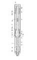
図1〜図3に示すように、筆記具1は、円筒状の軸筒2と、指で押すために軸筒2の周面側に設けられた操作部3と、軸筒2内に収容されて、軸筒2の前側に位置すると共に、操作部3の押圧により中心軸線Lを中心に回動する第1の回動部4と、軸筒2内に収容されて、第1の回動部4より後側に位置すると共に、第1の回動部4より大きな回転半径を有し、第1の回動部4と一緒に回動する第2の回動部5と、第2の回動部5の外周側に位置すると共に、第2の回動部5の回動を直線に変換して、筆記芯(例えばボールペン芯、サインペン芯)6を中心軸線Lの延在方向に移動させるカム機構7と、を備えている。
[First embodiment]
As shown in FIGS. 1 to 3, thewriting instrument 1 is accommodated in acylindrical shaft tube 2, anoperation unit 3 provided on the peripheral surface side of theshaft tube 2 for pressing with a finger, and theshaft tube 2. Thefirst rotation part 4 which is located on the front side of theshaft cylinder 2 and rotates about the central axis L by the pressing of theoperation part 3 and thefirst rotation part 4 housed in theshaft cylinder 2 and the first rotation A second rotatingpart 5 which is located behind thepart 4 and has a larger radius of rotation than the firstrotating part 4 and which rotates together with the firstrotating part 4; It is located on the outer peripheral side of therotation unit 5 and converts the rotation of thesecond rotation unit 5 into a straight line and moves the writing core (for example, a ballpoint pen core or a sign pen core) 6 in the extending direction of the central axis L. And acam mechanism 7 to be operated.

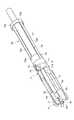
軸筒2は、円筒状の軸筒本体2Aと、軸筒本体2Aの先端にネジ結合された円錐状の口金2Bとからなる。軸筒2の後端は、エンドキャップ8によって蓋がされている。  Theshaft tube 2 includes acylindrical shaft body 2A and aconical base 2B screwed to the tip of theshaft body 2A. The rear end of theshaft cylinder 2 is covered with anend cap 8.

図3及び図4に示すように、操作部3には、軸筒本体2Aに形成されたコ字状の切欠き部2aによって軸筒本体2Aの一部として中心軸線Lの延在方向に延在する長尺状のレバー部(操作本体部)3aと、レバー部3aの先端側で第1の回動部4に向かって突出すると共に、第1の回動部4の外周面を略接線方向に押圧して、第1の回動部4を矢印A方向に回動させる作動片3bとが設けられている。そして、レバー部3aと作動片3bとの連結部分は、作動片3bを揺動可能にする薄肉の首部3cとして形成されている。  As shown in FIGS. 3 and 4, theoperation portion 3 extends in the extending direction of the central axis L as a part of the shaft cylindermain body 2A by aU-shaped notch 2a formed in the shaft cylindermain body 2A. A long lever portion (operation main body portion) 3a that exists and protrudes toward the first rotatingportion 4 at the distal end side of thelever portion 3a, and the outer peripheral surface of the first rotatingportion 4 is substantially tangent. Anoperating piece 3b is provided that presses in the direction and rotates the first rotatingportion 4 in the direction of arrow A. And the connection part of thelever part 3a and theaction piece 3b is formed as the thin neck part 3c which enables theaction piece 3b to rock | fluctuate.

レバー部3aは、軸筒本体2Aの周方向で120度毎に3個設けられ、これに対応して作動片3bも3個設けられている。また、レバー部3aの先端側には、筆記具1を握ったときに3本の指が確実に当たるように、軸筒本体2Aの外周面より突出する指当て部3dが一体に形成されている。このように構成することで、3本の指で各レバー部3aの指当て部3dを押すことができるので、1本のレバー部で第1の回動部4を回動させる場合に比べて、各レバー部3aに加わる力を低減させることができ、これによって、レバー部3aの操作性が良好になる。  Threelever portions 3a are provided every 120 degrees in the circumferential direction of the shaft cylindermain body 2A, and threeoperation pieces 3b are also provided correspondingly. In addition, afinger rest 3d that protrudes from the outer peripheral surface of the shaft cylindermain body 2A is integrally formed on the distal end side of thelever portion 3a so that the three fingers reliably come into contact with thewriting instrument 1. By configuring in this way, thefinger contact part 3d of eachlever part 3a can be pushed with three fingers, so compared with the case where the firstrotating part 4 is rotated with one lever part. The force applied to eachlever portion 3a can be reduced, and the operability of thelever portion 3a is thereby improved.

作動片3bの先端は、第1の回動部4の外周面に設けられた凹状の力点部4a内に嵌り込んでいるので、作動片3bの押圧力を第1の回動部4にしっかり伝えることができる。更に、第1の回動部4の外周面には、略径方向に突出して作動片3bを係止させる係止片4bが形成され、各係止片4bは、凹状の力点部4aのそれぞれに隣接して中心軸線Lの延在方向に延在している。  Since the tip of theoperating piece 3b is fitted in aconcave force point 4a provided on the outer peripheral surface of the firstrotating part 4, the pressing force of theoperating piece 3b is firmly applied to the firstrotating part 4. I can tell you. Furthermore, the outer peripheral surface of the1st rotation part 4 is formed in the substantially radial direction, and thelatching piece 4b which latches the action |operation piece 3b is formed, and each latchingpiece 4b is each of the concaveforce point part 4a. Is extended in the extending direction of the central axis L.

作動片3bが第1の回動部4を所定角度だけ回動させるとき、第1の回動部4に設けられた凹状の力点部4aに作動片3bの先端が当接することで、作動片3bによって第1の回動部4を確実に所定角度だけ回動させることができる。また、係止片4bの遊端は、第1の回動部4の回動時に、軸筒本体2Aの内周面に沿って摺動するので、第1の回動部4の回動を安定させる役目も有している。  When theoperating piece 3b rotates the firstrotating portion 4 by a predetermined angle, the tip of theoperating piece 3b comes into contact with the concaveforce point portion 4a provided in the firstrotating portion 4 so that the operating piece Thefirst rotation part 4 can be reliably rotated by a predetermined angle by 3b. Further, since the free end of thelocking piece 4b slides along the inner peripheral surface of the shaft cylindermain body 2A when the firstrotating part 4 is rotated, the firstrotating part 4 is rotated. It also has the role of stabilizing.

また、第1の回動部4の先端には、軸筒本体2Aの前端壁2d(図2参照)に対する回動摩擦を低減するためのリング状の突起部4cが設けられている。これによって、係止片4bが軸筒本体2Aの前端壁2dに当たることなく、第1の回動部4をスムーズに回動させることができる。  Further, a ring-shapedprotrusion 4c for reducing rotational friction with respect to thefront end wall 2d (see FIG. 2) of the shaft cylindermain body 2A is provided at the tip of the firstrotating portion 4. As a result, thefirst rotation portion 4 can be smoothly rotated without thelocking piece 4b hitting thefront end wall 2d of the shaft cylindermain body 2A.

図2及び図3に示すように、第2の回動部5は、円筒状に形成され、筆記芯6の通過が可能な連結パイプ9で第1の回動部4に連結されている。第1の回動部4の中央には、筆記芯6の通過が可能な貫通孔4dが形成され、この貫通孔4dと連結パイプ9とを一致させることで、筆記具1の中心軸線Lに沿って筆記芯6を配置させることができる。  As shown in FIGS. 2 and 3, the secondrotating part 5 is formed in a cylindrical shape and is connected to the firstrotating part 4 by a connectingpipe 9 through which thewriting core 6 can pass. A throughhole 4d through which thewriting core 6 can pass is formed at the center of the firstrotating portion 4, and the throughhole 4d and the connectingpipe 9 are aligned with each other along the central axis L of thewriting instrument 1. Thewriting core 6 can be arranged.

第2の回動部5の後端には、中心軸線Lを挟むように対をなして中心軸線Lの延在方向に延在する2本の弾性片10aを有する捻りバネ10が固定されている。各弾性片10aは、捻り復元力を有する樹脂によって形成されている。各弾性片10aの前端は、第2の回動部5と一体をなし、各弾性片10aの後端は、リング部10bと一体をなしている。そして、リング部10bに形成された突起部10cが、軸筒本体2Aの内周面に沿って中心軸線Lの延在方向に延在するスリット2bに嵌り込むことで、捻りバネ10の後端が軸筒本体2Aに対し周方向において固定され、これにより、第2の回動部5の回動復帰を可能にしている。  Atorsion spring 10 having twoelastic pieces 10a extending in the extending direction of the central axis L in a pair so as to sandwich the central axis L is fixed to the rear end of the secondrotating portion 5. Yes. Eachelastic piece 10a is formed of a resin having a twist restoring force. The front end of eachelastic piece 10a is integrated with the secondrotating portion 5, and the rear end of eachelastic piece 10a is integrated with thering portion 10b. And theprotrusion 10c formed in thering part 10b fits into theslit 2b extending in the extending direction of the central axis L along the inner peripheral surface of the shaft tubemain body 2A, so that the rear end of thetorsion spring 10 Is fixed in the circumferential direction with respect to the shaft cylindermain body 2A, thereby enabling the secondrotating portion 5 to return to rotation.

このような構成の捻りバネ10を採用することで、捻りコイルバネ等を利用した場合に比較して、筆記具1の軽量化、部品点数の削減、バネ機能の組み込み易さの実現が可能になる。  By adopting thetorsion spring 10 having such a configuration, thewriting instrument 1 can be reduced in weight, the number of parts can be reduced, and the spring function can be easily incorporated as compared with the case where a torsion coil spring or the like is used.

次に、周方向で180度毎に配置された2個一組のカム機構7について説明する。  Next, a set of twocam mechanisms 7 arranged every 180 degrees in the circumferential direction will be described.

図3及び図5に示すように、それぞれのカム機構7は、第2の回動部5の外周面上で傾斜して延在するカム部11と、筆記芯6が固定されたホルダ12の先端に設けられて、カム部11に係合するカムフォロア13とからなる。  As shown in FIGS. 3 and 5, eachcam mechanism 7 includes acam portion 11 extending obliquely on the outer peripheral surface of the secondrotating portion 5, and aholder 12 to which thewriting core 6 is fixed. Thecam follower 13 is provided at the tip and engages with thecam portion 11.

カム部11は、第2の回動部5の外周面に形成された開口部14の輪郭の一部として形成され、中心軸線Lに対して斜めになるように延在する。中心軸線Lとカム部11とのなす角度をカム角度αとした場合、カム角度αが大きくなればなる程、筆記芯6を所定量だけ移動させる際に、第2の回動部5の回動角度が大きくなる。カム部11の終端側には、第2の回動部5の周方向に延在してカムフォロア13を係止させる係止部11aが設けられている。  Thecam portion 11 is formed as a part of the outline of the openingportion 14 formed on the outer peripheral surface of the secondrotating portion 5, and extends so as to be inclined with respect to the central axis L. When the angle formed by the center axis L and thecam portion 11 is the cam angle α, the larger the cam angle α, the more the rotation of the secondrotating portion 5 is performed when thewriting core 6 is moved by a predetermined amount. The moving angle increases. A lockingportion 11 a that extends in the circumferential direction of the secondrotating portion 5 and locks thecam follower 13 is provided on the terminal end side of thecam portion 11.

この係止部11aにカムフォロア13が係止されることで、レバー部3aの指当て部3dから指の力を抜いてもレバー部3aが直ぐには戻らず、僅かなタイムラグをもってレバー部3aの復帰動作を行わせることができる。これにより、レバー部3aの指当て部3dの操作感の更なる向上を図ることができる。  Since thecam follower 13 is locked to the lockingportion 11a, thelever portion 3a does not return immediately even if the finger force is removed from thefinger contact portion 3d of thelever portion 3a, and thelever portion 3a returns with a slight time lag. The action can be performed. Thereby, the further improvement of the operation feeling of the finger |toe contact part 3d of thelever part 3a can be aimed at.

ホルダ12の先端側には、第2の回動部5の内側に位置する内筒部16が設けられ、この内筒部16の外周面には、カム部11に沿って移動するカムフォロア13が突起部として形成されている。ホルダ12には、筆記芯6を圧入固定させるためのパイプ状のホルダ本体部17が設けられ、このホルダ本体部17の先端は内筒部16の端面と一体になっている。  Aninner cylinder part 16 positioned inside thesecond rotation part 5 is provided on the tip end side of theholder 12, and acam follower 13 that moves along thecam part 11 is provided on the outer peripheral surface of theinner cylinder part 16. It is formed as a protrusion. Theholder 12 is provided with a pipe-shaped holdermain body portion 17 for press-fitting and fixing thewriting core 6, and the tip of the holdermain body portion 17 is integrated with the end surface of theinner cylinder portion 16.

また、内筒部16には、軸筒本体2Aの内周面に形成されたスリット2bに嵌り込む突起部16aが形成されている。スリット2bと突起部16aとの協働により、ホルダ12及び筆記芯6を中心軸線Lの延在方向に確実に移動させることができる。ホルダ12のガタツキを防止するために、ホルダ12の後部は、エンドキャップ8の差込み孔8a内に挿入されている。  Further, theinner cylinder part 16 is formed with aprotrusion 16a that fits into aslit 2b formed on the inner peripheral surface of the shaft cylindermain body 2A. By the cooperation of theslit 2b and theprotrusion 16a, theholder 12 and thewriting core 6 can be reliably moved in the extending direction of the central axis L. In order to prevent theholder 12 from rattling, the rear portion of theholder 12 is inserted into theinsertion hole 8 a of theend cap 8.

さらに、第2の回動部5と内筒部16との間には、第1のコイルバネ18が配置され、捻りバネ10の後端とエンドキャップ8との間に第2のコイルバネ19が配置されている。第2のコイルバネ19で捻りバネ10を付勢することにより、第1の回動部4が軸筒本体2Aの前端壁2dに軽く押圧され、第1の回動部4のガタツキを防止することができる。第1のコイルバネ18により、定常状態でホルダ12及び筆記芯6を確実に後退させておくことができる。  Further, afirst coil spring 18 is disposed between the secondrotating portion 5 and theinner cylinder portion 16, and asecond coil spring 19 is disposed between the rear end of thetorsion spring 10 and theend cap 8. Has been. By biasing thetorsion spring 10 with thesecond coil spring 19, the firstrotating part 4 is lightly pressed against thefront end wall 2 d of the shaft cylindermain body 2 </ b> A, thereby preventing rattling of the firstrotating part 4. Can do. Thefirst coil spring 18 can reliably retract theholder 12 and thewriting core 6 in a steady state.

筆記具1の動作を簡単に説明する。  The operation of thewriting instrument 1 will be briefly described.

筆記具1を指で握って、各レバー部3aの指当て部3dを指で押し込むと、作動片3bの先端が力点部4aを押すことで、第1の回動部4が所定の回動角だけ矢印A方向に回動する(図4(b)参照)。この回動と同時に第2の回動部5も回動し(図4(c)参照)、図6に示すように、カム部11に沿ってカムフォロア13が中心軸線Lの延在方向に前側に向かって移動する。このカムフォロア13の移動に追従してホルダ12及び筆記芯6が中心軸線Lの延在方向に前進する。そして、最終的に係止部11aにカムフォロア13が当たって、筆記芯6が軸筒2から最大限突出する。このとき、捻りバネ10の各弾性片10aは、最大限捻られた状態になっている。  When thewriting instrument 1 is grasped with a finger and thefinger contact part 3d of eachlever part 3a is pushed in with the finger, the tip of theoperating piece 3b pushes theforce point part 4a, whereby thefirst turning part 4 has a predetermined turning angle. Only in the direction of arrow A (see FIG. 4B). Simultaneously with this rotation, the secondrotating portion 5 also rotates (see FIG. 4C), and as shown in FIG. 6, thecam follower 13 moves forward along thecam portion 11 in the direction in which the central axis L extends. Move towards. Following the movement of thecam follower 13, theholder 12 and thewriting core 6 advance in the extending direction of the central axis L. Finally, thecam follower 13 hits the lockingportion 11a, and thewriting core 6 protrudes from theshaft cylinder 2 to the maximum extent. At this time, eachelastic piece 10a of thetorsion spring 10 is twisted to the maximum.

その後、各レバー部3aの指当て部3dを押す力を緩めることで、第1のコイルバネ18及び捻りバネ10の各弾性片10aの弾性力によって、第1及び第2の回動部4,5が逆回動を開始し、カム部11に沿ってカムフォロア13が中心軸線Lの延在方向に後退する。そして、カムフォロア13の移動に追従してホルダ12及び筆記芯6が中心軸線Lの延在方向に後退し、筆記芯6の先端が軸筒2内に格納される。このように、筆記具1は、持ち替えなしに、筆記芯6を出没させることができ、ノック機構をもった筆記具のような持ち替えの煩わしさが無い。  Thereafter, the first and secondrotating parts 4, 5 are loosened by the elastic force of theelastic pieces 10a of thefirst coil spring 18 and thetorsion spring 10 by loosening the force of pushing thefinger rest part 3d of eachlever part 3a. Starts reverse rotation, and thecam follower 13 moves back in the extending direction of the central axis L along thecam portion 11. Then, following the movement of thecam follower 13, theholder 12 and thewriting core 6 are retracted in the extending direction of the central axis L, and the tip of thewriting core 6 is stored in theshaft cylinder 2. In this way, thewriting instrument 1 can cause thewriting core 6 to appear and disappear without changing, and there is no need to change the holding like a writing instrument having a knock mechanism.

このような筆記具1では、小さい回転半径で回動する第1の回動部4を操作部3によって中心軸線Lを中心に回動させ、この第1の回動部4と一緒に、大きい回転半径で第2の回動部5が回動し、この第2の回動部5の周側にカム機構7が配置される構成になっている。従って、操作部3による第1の回動部4の回動量が第2の回動部5で増幅され、第1の回動部4が少ない回動量であっても第2の回動部5で大きな回動量が得られる。そして、増幅された回動量を利用して、カム機構7により第2の回動部5の回動運動を直線運動に変換し、この直線運動により筆記芯6を中心軸線Lに沿って大きく突出させることができる。  In such awriting instrument 1, thefirst rotation unit 4 that rotates with a small rotation radius is rotated about the central axis L by theoperation unit 3, and thefirst rotation unit 4 rotates together with thefirst rotation unit 4. The secondrotating portion 5 rotates with a radius, and thecam mechanism 7 is arranged on the circumferential side of the secondrotating portion 5. Accordingly, the amount of rotation of thefirst rotation unit 4 by theoperation unit 3 is amplified by thesecond rotation unit 5, and even if thefirst rotation unit 4 has a small rotation amount, thesecond rotation unit 5. A large amount of rotation can be obtained. Then, using the amplified amount of rotation, thecam mechanism 7 converts the rotation motion of thesecond rotation portion 5 into a linear motion, and the linear motion causes thewriting core 6 to largely protrude along the central axis L. Can be made.

図4(c)に示すように、操作部3の押込み操作量が少なく、第1の回動部4の回動量(矢印B参照)が例え少なくても、第2の回動部5の増幅作用(矢印C参照)により、筆記芯6を大きく移動させることができる。従って、操作部3の押込み操作量が少なくて済むので、筆記中における操作部3の操作感を良好にするといった優れた効果が得られる。  As shown in FIG. 4C, even if the pushing operation amount of theoperation unit 3 is small and the rotation amount of the first rotation unit 4 (see arrow B) is small, thesecond rotation unit 5 is amplified. Thewriting core 6 can be moved greatly by the action (see arrow C). Therefore, since the amount of pressing operation of theoperation unit 3 is small, an excellent effect of improving the operational feeling of theoperation unit 3 during writing can be obtained.

[第2の実施形態]
第2の実施形態に係る筆記具20は、第1の実施形態に係る筆記具1と同様の軸筒2と、操作部3と、第1の回動部4と、捻りバネ10とを備えているので、これらの詳細な説明は省略する。
[Second Embodiment]
The writinginstrument 20 according to the second embodiment includes ashaft cylinder 2, anoperation unit 3, a firstrotating unit 4, and atorsion spring 10 similar to thewriting instrument 1 according to the first embodiment. Therefore, detailed description thereof will be omitted.

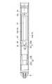
図7及び図8に示すように、第1の回動部4より大きな回転半径を有する第2の回動部21は、円筒状に形成され、筆記芯6の通過が可能で中心軸線Lの延在方向に伸縮自在な連結パイプ22によって第1の回動部4に連結されている。第1の回動部4の中央には、筆記芯6の通過が可能な貫通孔4cが形成され、この貫通孔4cの孔中心と連結パイプ22の孔中心とを一致させることで、筆記具20の中心軸線Lに沿って筆記芯6を配置させることができる。  As shown in FIG. 7 and FIG. 8, the second rotatingportion 21 having a larger turning radius than the firstrotating portion 4 is formed in a cylindrical shape so that thewriting core 6 can pass therethrough and the center axis L can be passed. It is connected to the1st rotation part 4 by theconnection pipe 22 which can be expanded-contracted in the extending direction. A throughhole 4c through which thewriting core 6 can pass is formed in the center of the firstrotating portion 4. By aligning the hole center of the throughhole 4c with the hole center of the connectingpipe 22, thewriting tool 20 is provided. Thewriting core 6 can be arranged along the central axis L.

連結パイプ22は、前端が第1の回動部4に固定されると共に、外周面で中心軸線Lの延在方向に延在するスライドレール22aが形成された第1のパイプ部22Aと、後端が第2の回動部21に固定されると共に、内周面でスライドレール22aが嵌り込むスライド溝22bが形成された第2のパイプ部22Bとからなる。このような構成によって、第1の回動部4と第2の回動部21とを一緒に回すことができると同時に、第1の回動部4に対して第2の回動部21を中心軸線Lの延在方向に移動させることができる。  The connectingpipe 22 has a front end fixed to the firstrotating portion 4 and afirst pipe portion 22A in which aslide rail 22a extending in the extending direction of the central axis L is formed on the outer peripheral surface, and the rear The end is fixed to the second rotatingportion 21 and includes asecond pipe portion 22B in which aslide groove 22b into which theslide rail 22a is fitted is formed on the inner peripheral surface. With such a configuration, the firstrotating unit 4 and the secondrotating unit 21 can be rotated together, and at the same time, the secondrotating unit 21 is moved with respect to the firstrotating unit 4. It can be moved in the extending direction of the central axis L.

次に、周方向で180度毎に配置された2個一組のカム機構23について説明する。  Next, a set of twocam mechanisms 23 arranged every 180 degrees in the circumferential direction will be described.

それぞれのカム機構23は、第2の回動部21の周側に位置すると共に、第2の回動部21の回動を直線に変換して、筆記芯(例えばボールペン芯、サインペン芯)6を中心軸線Lの延在方向に移動させる。さらに、各カム機構23は、第2の回動部21の外周面上で傾斜して延在するカム部24と、軸筒本体2Aの内面から突出するように形成されてカム部24に係合するガイド突起25とからなる。  Eachcam mechanism 23 is located on the peripheral side of the secondrotating unit 21 and converts the rotation of the secondrotating unit 21 into a straight line, so that a writing core (for example, a ballpoint pen core or a sign pen core) 6 is formed. Is moved in the extending direction of the central axis L. Furthermore, eachcam mechanism 23 is formed so as to protrude from the inner surface of the shaft cylindermain body 2 </ b> A by being inclined and extended on the outer peripheral surface of the second rotatingportion 21. And aguide projection 25 to be joined.

カム部24は、第2の回動部21の外周面に形成された凹部26の輪郭の一部として形成され、中心軸線Lに対して斜めになるように延在する。中心軸線Lとカム部24とのなす角度をカム角度αとした場合、カム角度αが大きくなればなる程、筆記芯6を所定量だけ移動させる際に、第2の回動部21の回動角度が大きくなる。カム部24の終端側には、第2の回動部21の周方向に延在してガイド突起25を係止させる係止部24aが設けられている。  Thecam portion 24 is formed as a part of the contour of theconcave portion 26 formed on the outer peripheral surface of the second rotatingportion 21, and extends so as to be inclined with respect to the central axis L. When the angle formed by the central axis L and thecam portion 24 is the cam angle α, the larger the cam angle α, the more the rotation of the second rotatingportion 21 when thewriting core 6 is moved by a predetermined amount. The moving angle increases. A lockingportion 24 a that extends in the circumferential direction of the second rotatingportion 21 and locks theguide protrusion 25 is provided on the terminal end side of thecam portion 24.

この係止部24aにガイド突起25が係止されることで、レバー部3aの指当て部3dから指の力を抜いてもレバー部3aが直ぐには戻らず、僅かなタイムラグをもってレバー部3aの復帰動作を行わせることができる。これにより、レバー部3aの指当て部3dの操作感の更なる向上を図ることができる。  Since theguide protrusion 25 is locked to the lockingportion 24a, thelever portion 3a does not return immediately even if the finger force is removed from thefinger contact portion 3d of thelever portion 3a, and thelever portion 3a has a slight time lag. A return operation can be performed. Thereby, the further improvement of the operation feeling of the finger |toe contact part 3d of thelever part 3a can be aimed at.

第2の回動部21の後端には、パイプ状のホルダ27が一体に形成され、このホルダ27は、中心軸線Lに沿って延在し、筆記芯6の後部が圧入固定されている。また、ホルダ27のガタツキを防止するために、ホルダ27の後部は、エンドキャップ8の差込み孔8a内に挿入されている。  A pipe-shapedholder 27 is integrally formed at the rear end of the second rotatingportion 21. Theholder 27 extends along the central axis L, and the rear portion of thewriting core 6 is press-fitted and fixed. . In order to prevent theholder 27 from rattling, the rear part of theholder 27 is inserted into theinsertion hole 8 a of theend cap 8.

さらに、第1の回動部4と第2の回動部21との間には、コイルバネ28が配置され、このコイルバネ28により、第1の回動部4が軸筒本体2Aの前端壁2dに軽く押圧され、第1の回動部4のガタツキを防止することができ、しかも、定常状態でホルダ27及び筆記芯6を確実に後退させておくことができる。  Further, acoil spring 28 is disposed between the firstrotating portion 4 and the second rotatingportion 21, and the firstrotating portion 4 causes thefront end wall 2 d of theshaft cylinder body 2 </ b> A to be arranged by thecoil spring 28. Theholder 27 and thewriting core 6 can be reliably retracted in a steady state.

筆記具20の動作を簡単に説明する。  The operation of the writinginstrument 20 will be briefly described.

筆記具20を指で握って、各レバー部3aの指当て部3dを指で押し込むと、作動片3bにより第1の回動部4が所定の回動角だけ回動する(図4参照)。この回動と同時に第2の回動部21も回動し、図9に示すように、カム部24に沿ってガイド突起25が摺動し、連結パイプ22が収縮しながら第2の回動部21自体が中心軸線Lの延在方向に前側に向かって移動する。この第2の回動部21の移動に追従してホルダ27及び筆記芯6が中心軸線Lの延在方向に前進する。そして、最終的に係止部24aにガイド突起25が当たって、筆記芯6が軸筒2から最大限突出する。このとき、捻りコイルバネ10の突起部10cがスリット2bに沿って中心軸線Lの延在方向に移動し、捻りバネ10の各弾性片10aは、最大限捻られた状態になっている。  When the writinginstrument 20 is grasped with a finger and thefinger contact portion 3d of eachlever portion 3a is pushed in with the finger, thefirst turning portion 4 is turned by a predetermined turning angle by theoperating piece 3b (see FIG. 4). Simultaneously with this rotation, thesecond rotation portion 21 also rotates, and as shown in FIG. 9, theguide protrusion 25 slides along thecam portion 24, and theconnection pipe 22 contracts, causing the second rotation. Thepart 21 itself moves toward the front side in the extending direction of the central axis L. Following the movement of the second rotatingportion 21, theholder 27 and thewriting core 6 advance in the extending direction of the central axis L. Finally, theguide protrusion 25 hits the lockingportion 24a, and thewriting core 6 protrudes from theshaft cylinder 2 to the maximum extent. At this time, theprotrusion 10c of thetorsion coil spring 10 moves in the extending direction of the central axis L along theslit 2b, and eachelastic piece 10a of thetorsion spring 10 is in a state of being twisted to the maximum.

その後、各レバー部3aの指当て部3dを押す力を緩めることで、コイルバネ28及び捻りバネ10の各弾性片10aの弾性力によって、第1及び第2の回動部4,21が逆回動を開始し、カム部24に沿ってガイド突起25が摺動する。そして、ガイド突起25の移動に追従してホルダ27及び筆記芯6が中心軸線Lの延在方向に後退し、筆記芯6の先端が軸筒2内に格納される。このように、筆記具20は、持ち替えなしに、筆記芯6を出没させることができ、ノック機構をもった筆記具のような持ち替えの煩わしさが無い。  After that, the first and secondrotating parts 4 and 21 are rotated in reverse by the elastic force of theelastic pieces 10a of thecoil spring 28 and thetorsion spring 10 by loosening the force of pressing thefinger rest part 3d of eachlever part 3a. Theguide protrusion 25 slides along thecam portion 24. Then, following the movement of theguide protrusion 25, theholder 27 and thewriting core 6 are retracted in the extending direction of the central axis L, and the tip of thewriting core 6 is stored in theshaft tube 2. As described above, thewriting tool 20 can cause thewriting core 6 to appear and disappear without changing, and there is no trouble of changing like a writing tool having a knock mechanism.

[第3の実施形態]
第3の実施形態に係る筆記具30は、第1の実施形態に係る筆記具1と同様の軸筒2と、操作部3と、第1の回動部4と、捻りバネ10とを備えているので、これらの詳細な説明は省略する。
[Third embodiment]
The writinginstrument 30 according to the third embodiment includes ashaft cylinder 2, anoperation unit 3, a firstrotating unit 4, and atorsion spring 10 similar to thewriting instrument 1 according to the first embodiment. Therefore, detailed description thereof will be omitted.

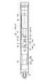
図10及び図11に示すように、第1の回動部4より大きな回転半径を有する第2の回動部31は、円筒状に形成され、筆記芯6の通過が可能で中心軸線Lの延在方向に伸縮自在な連結パイプ22によって第1の回動部4に連結されている。第1の回動部4の中央には、筆記芯6の通過が可能な貫通孔4cが形成され、この貫通孔4cの孔中心と連結パイプ22の孔中心とを一致させることで、筆記具30の中心軸線Lに沿って筆記芯6を配置させることができる。  As shown in FIG. 10 and FIG. 11, the secondrotating part 31 having a larger turning radius than the firstrotating part 4 is formed in a cylindrical shape and allows thewriting core 6 to pass therethrough. It is connected to the1st rotation part 4 by theconnection pipe 22 which can be expanded-contracted in the extending direction. A throughhole 4c through which thewriting core 6 can pass is formed at the center of the firstrotating portion 4, and thewriting tool 30 is formed by matching the hole center of the throughhole 4c with the hole center of the connectingpipe 22. Thewriting core 6 can be arranged along the central axis L.

連結パイプ22は、前端が第1の回動部4に固定されると共に、外周面で中心軸線Lの延在方向に延在するスライドレール22aが形成された第1のパイプ部22Aと、後端が第2の回動部31に固定されると共に、内周面でスライドレール22aが嵌り込むスライド溝22bが形成された第2のパイプ部22Bとからなる。このような構成によって、第1の回動部4と第2の回動部31とを一緒に回すことができると同時に、第1の回動部4に対して第2の回動部31を中心軸線Lの延在方向に移動させることができる。  The connectingpipe 22 has a front end fixed to the firstrotating portion 4 and afirst pipe portion 22A in which aslide rail 22a extending in the extending direction of the central axis L is formed on the outer peripheral surface, and the rear The end is fixed to the second rotatingportion 31 and includes asecond pipe portion 22B in which aslide groove 22b into which theslide rail 22a is fitted is formed on the inner peripheral surface. With such a configuration, the firstrotating unit 4 and the secondrotating unit 31 can be rotated together, and at the same time, the secondrotating unit 31 is moved with respect to the firstrotating unit 4. It can be moved in the extending direction of the central axis L.

次に、周方向で180度毎に配置された2個一組のカム機構33について説明する。  Next, a set of twocam mechanisms 33 arranged every 180 degrees in the circumferential direction will be described.

それぞれのカム機構33は、第2の回動部31の周側に位置すると共に、第2の回動部31の回動を直線に変換して、筆記芯(例えばボールペン芯、サインペン芯)6を中心軸線Lの延在方向に移動させる。さらに、各カム機構33は、第2の回動部31の外周面上で傾斜して略ハ字状に延在する第1及び第2のカム部34,35と、軸筒本体2Aの内面に突出するように形成されて第1のカム部34に係合する第1のガイド突起36と、筆記芯6が固定されたホルダ38の先端に設けられて、第2のカム部35に係合する第2のガイド突起37と、からなる。  Eachcam mechanism 33 is located on the circumferential side of thesecond rotation unit 31 and converts the rotation of thesecond rotation unit 31 into a straight line, so that a writing core (for example, a ballpoint pen core or a sign pen core) 6 is formed. Is moved in the extending direction of the central axis L. Further, eachcam mechanism 33 includes first andsecond cam portions 34 and 35 which are inclined on the outer peripheral surface of the second rotatingportion 31 and extend in a substantially C shape, and the inner surface of the shaft cylindermain body 2A. Thefirst guide protrusion 36 that is formed so as to protrude to thefirst cam portion 34 and the tip of theholder 38 to which thewriting core 6 is fixed is connected to thesecond cam portion 35. And asecond guide projection 37 to be joined.

そして、第2の回動部31は、第1のカム部34及び第1のガイド突起36を介して、軸筒2に対し中心軸線Lの延在方向に摺動自在に連結され、ホルダ38は、第2のカム部35及び第2のガイド突起37を介して、第2の回動部31に対し中心軸線Lの延在方向に摺動自在に連結されている。  The secondrotating portion 31 is slidably connected to theshaft tube 2 in the extending direction of the central axis L via thefirst cam portion 34 and thefirst guide protrusion 36, and aholder 38. Is connected to the second rotatingportion 31 through thesecond cam portion 35 and thesecond guide protrusion 37 so as to be slidable in the extending direction of the central axis L.

中心軸線Lの延在方向に並設された第1のカム部34と第2のカム部35は、第2の回動部31の外周面に形成された開口部39の輪郭の一部として形成され、中心軸線Lに対して斜めになるように延在し、中心軸線Lに直交する面に対して対称の関係を有する。中心軸線Lと第1のカム部34とのなす角度及び中心軸線Lと第2のカム部35とのなす角度をカム角度αとした場合、カム角度αが大きくなればなる程、筆記芯6を所定量だけ移動させる際に、第2の回動部31の回動角度が大きくなる。なお、第1のカム部34側のカム角度αと第2のカム部35のカム角度αは、同じであっても異っていてもよい。さらに、第1及び第2のカム部34,35の終端側には、第2の回動部31の周方向に延在して第1及び第2のガイド突起36,37を係止させる係止部34a,35aが設けられている。  Thefirst cam portion 34 and thesecond cam portion 35 arranged side by side in the extending direction of the central axis L are part of the contour of theopening 39 formed on the outer peripheral surface of the second rotatingportion 31. It is formed, extends so as to be inclined with respect to the central axis L, and has a symmetric relationship with respect to a plane orthogonal to the central axis L. When the angle formed between the central axis L and thefirst cam portion 34 and the angle formed between the central axis L and thesecond cam portion 35 are defined as the cam angle α, thewriting core 6 increases as the cam angle α increases. Is moved by a predetermined amount, the rotation angle of thesecond rotation unit 31 is increased. The cam angle α on thefirst cam portion 34 side and the cam angle α on thesecond cam portion 35 may be the same or different. Further, on the terminal end side of the first andsecond cam portions 34 and 35, a member extending in the circumferential direction of the second rotatingportion 31 and locking the first andsecond guide protrusions 36 and 37. Stopportions 34a and 35a are provided.

この係止部34a,35aに第1及び第2のガイド突起36,37が係止されることで、レバー部3aの指当て部3dから指の力を抜いてもレバー部3aが直ぐには戻らず、僅かなタイムラグをもってレバー部3aの復帰動作を行わせることができる。これにより、レバー部3aの指当て部3dの操作感の更なる向上を図ることができる。  When the first andsecond guide protrusions 36 and 37 are locked to thelocking portions 34a and 35a, thelever portion 3a returns immediately even if the finger force is removed from thefinger contact portion 3d of thelever portion 3a. However, the return operation of thelever portion 3a can be performed with a slight time lag. Thereby, the further improvement of the operation feeling of the finger |toe contact part 3d of thelever part 3a can be aimed at.

ホルダ38の先端側には、第2の回動部31の内側に位置する内筒部40が設けられ、この内筒部40の外周面には、第2のカム部35に沿って移動する第2のガイド突起37が形成されている。ホルダ38には、筆記芯6を圧入固定させるためのパイプ状のホルダ本体部41が設けられ、このホルダ本体部41の先端は内筒部40の端面と一体になっている。  Aninner cylinder part 40 located inside thesecond rotation part 31 is provided on the tip side of theholder 38, and moves along thesecond cam part 35 on the outer peripheral surface of theinner cylinder part 40. Asecond guide protrusion 37 is formed. Theholder 38 is provided with a pipe-like holdermain body 41 for press-fitting and fixing thewriting core 6, and the tip of the holdermain body 41 is integrated with the end surface of theinner cylinder portion 40.

また、内筒部40には、軸筒本体2Aの内周面に形成されたスリット2bに嵌り込む突起部40aが形成されている。スリット2bと突起部40aとの協働により、ホルダ38及び筆記芯6を中心軸線Lの延在方向に確実に移動させることができる。ホルダ38のガタツキを防止するために、ホルダ38の後部は、エンドキャップ8の差込み孔8a内に挿入されている。  Further, theinner cylinder portion 40 is formed with aprotrusion 40a that fits into aslit 2b formed on the inner peripheral surface of the shaft cylindermain body 2A. By the cooperation of theslit 2b and theprotrusion 40a, theholder 38 and thewriting core 6 can be reliably moved in the extending direction of the central axis L. In order to prevent theholder 38 from rattling, the rear portion of theholder 38 is inserted into theinsertion hole 8 a of theend cap 8.

さらに、第2の回動部31と内筒部40との間には、第1のコイルバネ43が配置され、第1の回動部4と第2の回動部31との間には第2のコイルバネ44が配置されている。第2のコイルバネ44で第1の回動部4が軸筒本体2Aの前端壁2dに軽く押圧され、第1の回動部4のガタツキを防止することができる。第1のコイルバネ43により、定常状態でホルダ38及び筆記芯6を確実に後退させておくことができる。  Further, afirst coil spring 43 is disposed between the secondrotating part 31 and theinner cylinder part 40, and afirst coil spring 43 is disposed between the firstrotating part 4 and the secondrotating part 31. Twocoil springs 44 are arranged. The firstrotating part 4 is lightly pressed by thesecond coil spring 44 against thefront end wall 2d of the shaft cylindermain body 2A, and the firstrotating part 4 can be prevented from rattling. Thefirst coil spring 43 can reliably retract theholder 38 and thewriting core 6 in a steady state.

筆記具30の動作を簡単に説明する。  The operation of the writinginstrument 30 will be briefly described.

筆記具30を指で握って、各レバー部3aの指当て部3dを指で押し込むと、作動片3bにより第1の回動部4が所定の回動角だけ回動する(図4参照)。この回動と同時に第2の回動部31も回動し、図12に示すように、第1及び第2のカム部34,35に沿って第1及び第2のガイド突起36,37が互いに近づくように摺動し、連結パイプ22が収縮しながら、第2の回動部31及びホルダ38が中心軸線Lの延在方向に前側に向かって移動する。これに伴って、筆記芯6が中心軸線Lの延在方向に前進する。そして、最終的に係止部34a,35aに第1及び第2のガイド突起36,37が当たって、筆記芯6が軸筒2から最大限突出する。このとき、捻りコイルバネ10の突起部10cがスリット2bに沿って中心軸線Lの延在方向に移動し、捻りバネ10の各弾性片10aは、最大限捻られた状態になっている。  When the writinginstrument 30 is grasped with a finger and thefinger contact part 3d of eachlever part 3a is pushed in with the finger, thefirst turning part 4 is turned by a predetermined turning angle by theoperating piece 3b (see FIG. 4). Simultaneously with this rotation, the second rotatingportion 31 also rotates, and as shown in FIG. 12, the first andsecond guide protrusions 36, 37 are formed along the first andsecond cam portions 34, 35. The secondrotating portion 31 and theholder 38 move toward the front side in the extending direction of the central axis L while sliding so as to approach each other and the connectingpipe 22 contracts. Accordingly, thewriting core 6 moves forward in the extending direction of the central axis L. Finally, the first andsecond guide protrusions 36 and 37 hit the lockingportions 34a and 35a, and thewriting core 6 protrudes from theshaft cylinder 2 to the maximum extent. At this time, theprotrusion 10c of thetorsion coil spring 10 moves in the extending direction of the central axis L along theslit 2b, and eachelastic piece 10a of thetorsion spring 10 is in a state of being twisted to the maximum.

その後、各レバー部3aの指当て部3dを押す力を緩めることで、第1コイルバネ43及び捻りバネ10の各弾性片10aの弾性力によって、第1及び第2の回動部4,31が逆回動を開始し、カム部34,35に沿ってガイド突起36,37が摺動する。そして、ガイド突起36,37の移動に追従して第2の回動部31及びホルダ38が中心軸線Lの延在方向に後退し、筆記芯6の先端が軸筒2内に格納される。このように、筆記具30は、持ち替えなしに、筆記芯6を出没させることができ、ノック機構をもった筆記具のような持ち替えの煩わしさが無い。  Thereafter, the first and secondrotating parts 4, 31 are moved by the elastic force of theelastic pieces 10 a of thefirst coil spring 43 and thetorsion spring 10 by loosening the force that pushes thefinger contact part 3 d of eachlever part 3 a. Reverse rotation is started, and theguide protrusions 36 and 37 slide along thecam portions 34 and 35. Then, following the movement of theguide protrusions 36 and 37, the second rotatingportion 31 and theholder 38 are retracted in the extending direction of the central axis L, and the tip of thewriting core 6 is stored in theshaft tube 2. As described above, thewriting tool 30 can cause thewriting core 6 to appear and disappear without changing, and there is no trouble of changing the writing like a writing tool having a knock mechanism.

そして、2個一対のカム部34,35とガイド突起36,37が採用され、レバー部3aの指当て部3dの極めて少ない押込み操作量によって、筆記芯6を軸筒2から出没させることができる。この場合の押込み操作量は、実施形態1,2の筆記具1,20の半分で、筆記芯6を軸筒2から同量だけ出没させることができる。  The pair ofcam portions 34 and 35 and theguide protrusions 36 and 37 are employed, and thewriting core 6 can be protruded and retracted from theshaft tube 2 with a very small pressing operation amount of thefinger contact portion 3d of thelever portion 3a. . In this case, the pushing operation amount is half that of thewriting tools 1 and 20 of the first and second embodiments, and thewriting core 6 can be made to appear and disappear from theshaft tube 2 by the same amount.

本発明は、前述した実施形態に限定されないことは言うまでもない。  It goes without saying that the present invention is not limited to the embodiment described above.

例えば、図8に示すように、捻りバネ50は、中心軸線Lを挟むように対をなして中心軸線Lの延在方向に延在する2本の弾性片50aを有し、捻り復元力を有する樹脂によって形成されている。各弾性片50aの前端は、第2の回動部5と一体をなし、各弾性片50aの後端は、軸筒2の後端に固定されるエンドキャップ8と一体をなしている。そして、エンドキャップ8が軸筒2に嵌り込むことで、捻りバネ50の後端が軸筒本体2Aに固定され、これにより、第2の回動部5の回動復帰を可能にしている。このような構成の捻りバネ50を採用することで、捻りコイルバネ等を利用した場合に比較して、筆記具1の軽量化、部品点数の削減、バネ機能の組み込み易さの実現が可能になる。  For example, as shown in FIG. 8, thetorsion spring 50 includes twoelastic pieces 50 a that extend in the extending direction of the central axis L so as to sandwich the central axis L, and provide a torsional restoring force. It is formed with the resin which has. The front end of eachelastic piece 50 a is integrated with the secondrotating portion 5, and the rear end of eachelastic piece 50 a is integrated with theend cap 8 fixed to the rear end of theshaft cylinder 2. Then, when theend cap 8 is fitted into theshaft cylinder 2, the rear end of thetorsion spring 50 is fixed to the shaft cylindermain body 2 </ b> A, thereby enabling the secondrotating portion 5 to return to rotation. By employing thetorsion spring 50 having such a configuration, thewriting instrument 1 can be reduced in weight, the number of parts can be reduced, and the spring function can be easily incorporated as compared with the case where a torsion coil spring or the like is used.

1,20,30…筆記具、2…軸筒、3…操作部、3a…操作本体部(レバー部)、3b…作動片、4…第1の回動部、4a…力点部、4b…係止片、5,21,31…第2の回動部、6…筆記芯、7,23,33…カム機構、10,50…捻りバネ、11,24,34,35…カム部、11a,24a,34a,35a…係止部、12,27,38…ホルダ、13…カムフォロア、25,36,37…ガイド突起、L…中心軸線。  DESCRIPTION OFSYMBOLS 1,20,30 ... Writing instrument, 2 ... Shaft cylinder, 3 ... Operation part, 3a ... Operation main-body part (lever part), 3b ... Actuation piece, 4 ... 1st rotation part, 4a ... Power point part, 4b ... Engagement Stop piece, 5, 21, 31 ... second rotation part, 6 ... writing core, 7, 23, 33 ... cam mechanism, 10, 50 ... torsion spring, 11, 24, 34, 35 ... cam part, 11a, 24a, 34a, 35a ... locking portion, 12, 27, 38 ... holder, 13 ... cam follower, 25, 36, 37 ... guide projection, L ... central axis.

Claims (7)

Translated fromJapanese
軸筒の外側に設けられた操作部を操作することによって筆記芯の先端を軸筒から突出させるように構成した筆記具において、
前記軸筒の前側に位置すると共に、前記操作部の押圧により前記中心軸線を中心に回動する第1の回動部と、
前記第1の回動部に設けられ、前記操作部の押圧力を受けて前記第1の回動部に回動力を伝達する力点部と、
前記第1の回動部より後側に位置し、前記第1の回動部と一緒に回動する第2の回動部と、
前記第2の回動部に設けられ、前記第2の回動部の回動を直線に変換して、前記筆記芯を前記中心軸線の延在方向に移動させるカム機構と、を有し、
前記カム機構が設けられた前記第2の回動部の回転半径は、前記力点部の回転半径よりも大きいことを特徴とする筆記具。
In the writing instrument configured to project the tip of the writing core from the shaft cylinder by operating the operation unit provided on the outside of the shaft cylinder,
A first rotation part that is located on the front side of the shaft cylinder and rotates around the central axis line by pressing of the operation part;
A force point portion that is provided in the first rotation portion, receives a pressing force of the operation portion, and transmits a rotational force to the first rotation portion;
A second rotation unit located behind the first rotation unit and rotating together with the first rotation unit;
A cam mechanism that is provided in the second rotation part, converts the rotation of the second rotation part into a straight line, and moves the writing core in the extending direction of the central axis,
The writing instrument according to claim 1, wherein a rotation radius of the second rotation portion provided with the cam mechanism is larger than a rotation radius of the power point portion.
前記操作部には、前記力点部と係合する作動片が設けられていることを特徴とする請求項1記載の筆記具。  The writing instrument according to claim 1, wherein an operating piece that engages with the power point portion is provided in the operation portion. 前記カム機構は、
前記第2の回動部の周上に位置するカム部と、
前記筆記芯が固定されたホルダに設けられて、前記カム部に係合するカムフォロアと、からなることを特徴とする請求項1又は2記載の筆記具。
The cam mechanism is
A cam portion located on the circumference of the second rotating portion;
The writing instrument according to claim 1, further comprising a cam follower that is provided on a holder to which the writing core is fixed and engages with the cam portion.
前記第1の回動部に対して前記第2の回動部は前記中心軸線の延在方向に摺動自在に連結され、前記第2の回動部には前記筆記芯が固定されるホルダが一体に連結され、
前記カム機構は、
前記第2の回動部の周上に位置するカム部と、
前記軸筒の内面に形成されて前記カム部に係合するガイド突起と、からなることを特徴とする請求項1又は2記載の筆記具。
A holder to which the second rotating part is slidably connected in the extending direction of the central axis with respect to the first rotating part, and the writing core is fixed to the second rotating part. Are connected together,
The cam mechanism is
A cam portion located on the circumference of the second rotating portion;
The writing instrument according to claim 1, further comprising a guide protrusion formed on an inner surface of the shaft cylinder and engaged with the cam portion.
前記第1の回動部に対して前記第2の回動部は前記中心軸線の延在方向に摺動自在に連結され、
前記カム機構は、
前記第2の回動部の周面上に位置する第1及び第2のカム部と、
前記軸筒の内面に形成されて前記第1のカム部に係合する第1のガイド突起と、
前記筆記芯が固定されたホルダに設けられて、前記第2のカム部に係合する第2のガイド突起と、からなることを特徴とする請求項1又は2記載の筆記具。
The second rotating portion is slidably connected in the extending direction of the central axis with respect to the first rotating portion,
The cam mechanism is
First and second cam portions located on a peripheral surface of the second rotating portion;
A first guide protrusion formed on an inner surface of the shaft tube and engaged with the first cam portion;
The writing instrument according to claim 1, further comprising: a second guide protrusion that is provided on a holder to which the writing core is fixed and engages with the second cam portion.
前記中心軸線の延在方向に沿って延在すると共に、一端が前記第2の回動部に連結され、他端が前記軸筒に固定される板状の捻りバネを更に備えたことを特徴とする請求項1〜3の何れか一項に記載の筆記具。  And a plate-shaped torsion spring that extends along the direction in which the central axis extends and has one end connected to the second rotating portion and the other end fixed to the shaft cylinder. The writing instrument according to any one of claims 1 to 3. 前記中心軸線の延在方向に沿って延在すると共に、一端が前記第2の回動部に連結され、他端が前記軸筒に対して周方向に固定され、前記中心軸線の延在方向に移動自在な捻りバネを更に備えたことを特徴とする1,2,4,5又は6記載の筆記具。  Extending along the extending direction of the central axis, one end is connected to the second rotating portion, the other end is fixed in the circumferential direction with respect to the shaft cylinder, and the extending direction of the central axis The writing instrument according to 1, 2, 4, 5, or 6, further comprising a torsion spring that is freely movable.
JP2009018274A2009-01-292009-01-29 Writing instrumentExpired - Fee RelatedJP5469346B2 (en)

Priority Applications (1)

Application NumberPriority DateFiling DateTitle
JP2009018274AJP5469346B2 (en)2009-01-292009-01-29 Writing instrument

Applications Claiming Priority (1)

Application NumberPriority DateFiling DateTitle
JP2009018274AJP5469346B2 (en)2009-01-292009-01-29 Writing instrument

Publications (2)

Publication NumberPublication Date
JP2010173174A JP2010173174A (en)2010-08-12
JP5469346B2true JP5469346B2 (en)2014-04-16

Family

ID=42704594

Family Applications (1)

Application NumberTitlePriority DateFiling Date
JP2009018274AExpired - Fee RelatedJP5469346B2 (en)2009-01-292009-01-29 Writing instrument

Country Status (1)

CountryLink
JP (1)JP5469346B2 (en)

Families Citing this family (1)

* Cited by examiner, † Cited by third party
Publication numberPriority datePublication dateAssigneeTitle
JP7479223B2 (en)2020-06-292024-05-08ゼブラ株式会社 Writing implements

Family Cites Families (4)

* Cited by examiner, † Cited by third party
Publication numberPriority datePublication dateAssigneeTitle
JP2607167Y2 (en)*1992-04-282001-04-16株式会社壽 Side knock ballpoint pen
US7066042B2 (en)*2004-01-072006-06-27Sanford L.P.Advancing/retracting mechanism
CN100484776C (en)*2005-02-032009-05-06桑福德有限合伙人公司Travel multiplier mechanisms for writing instruments
US7452149B2 (en)*2005-07-192008-11-18Kabushiki Kaisha Pilot CorporationRotating retractable writing instrument

Also Published As

Publication numberPublication date
JP2010173174A (en)2010-08-12

Similar Documents

PublicationPublication DateTitle
JP4768068B2 (en) Writing utensils with buffer devices
JP5373358B2 (en) mechanical pencil
KR20150064071A (en)Rotary operated writing instrument
JP2024087031A (en) Writing implements
CN108621641B (en)Press type writing tool
JP2011509848A (en) Writing instrument with eraser protected by sleeve
JP5469346B2 (en) Writing instrument
JP2001232987A (en)Side-knock type writing tool
JP2017094600A (en) Writing instrument
US11390111B2 (en)Writing implement
JP6267893B2 (en) Writing instrument
JP5469345B2 (en) Writing instrument
JP5070942B2 (en) Double writing instrument
JP5262088B2 (en) Writing instrument
JP4590267B2 (en) Writing instruments such as ballpoint pens
JP5373359B2 (en) mechanical pencil
JP5575510B2 (en) Writing instrument clip structure
JP5496046B2 (en) Writing instrument
JP3761504B2 (en) Side knock mechanical pencil
JP5373361B2 (en) mechanical pencil
JP6049062B2 (en) Rotating operation writing instrument
JP7619812B2 (en) Retractable writing implement
JP7688533B2 (en) Retractable writing instrument tip cover and retractable writing instrument equipped with said retractable writing instrument tip cover
JP4428000B2 (en) Rod body feeding device
JP2011088289A (en)Shaking-out type mechanical pencil

Legal Events

DateCodeTitleDescription
A621Written request for application examination

Free format text:JAPANESE INTERMEDIATE CODE: A621

Effective date:20111110

A977Report on retrieval

Free format text:JAPANESE INTERMEDIATE CODE: A971007

Effective date:20130228

A131Notification of reasons for refusal

Free format text:JAPANESE INTERMEDIATE CODE: A131

Effective date:20130305

A521Request for written amendment filed

Free format text:JAPANESE INTERMEDIATE CODE: A523

Effective date:20130502

TRDDDecision of grant or rejection written
A01Written decision to grant a patent or to grant a registration (utility model)

Free format text:JAPANESE INTERMEDIATE CODE: A01

Effective date:20140107

A61First payment of annual fees (during grant procedure)

Free format text:JAPANESE INTERMEDIATE CODE: A61

Effective date:20140131

R150Certificate of patent or registration of utility model

Ref document number:5469346

Country of ref document:JP

Free format text:JAPANESE INTERMEDIATE CODE: R150

Free format text:JAPANESE INTERMEDIATE CODE: R150

R250Receipt of annual fees

Free format text:JAPANESE INTERMEDIATE CODE: R250

R250Receipt of annual fees

Free format text:JAPANESE INTERMEDIATE CODE: R250

R250Receipt of annual fees

Free format text:JAPANESE INTERMEDIATE CODE: R250

R250Receipt of annual fees

Free format text:JAPANESE INTERMEDIATE CODE: R250

R250Receipt of annual fees

Free format text:JAPANESE INTERMEDIATE CODE: R250

R250Receipt of annual fees

Free format text:JAPANESE INTERMEDIATE CODE: R250

R250Receipt of annual fees

Free format text:JAPANESE INTERMEDIATE CODE: R250

LAPSCancellation because of no payment of annual fees

[8]ページ先頭

©2009-2025 Movatter.jp