JP5468276B2 - Bonding equipment - Google Patents
Bonding equipmentDownload PDFInfo
- Publication number
- JP5468276B2 JP5468276B2JP2009053069AJP2009053069AJP5468276B2JP 5468276 B2JP5468276 B2JP 5468276B2JP 2009053069 AJP2009053069 AJP 2009053069AJP 2009053069 AJP2009053069 AJP 2009053069AJP 5468276 B2JP5468276 B2JP 5468276B2
- Authority
- JP
- Japan
- Prior art keywords
- hot plate
- temperature
- air
- blower
- nozzle
- Prior art date
- Legal status (The legal status is an assumption and is not a legal conclusion. Google has not performed a legal analysis and makes no representation as to the accuracy of the status listed.)
- Expired - Fee Related
Links
Images


Landscapes
- Lining Or Joining Of Plastics Or The Like (AREA)
Description
Translated fromJapanese本発明は、布にテープを接着するボンディング装置に関する。 The present invention relates to a bonding apparatus for bonding a tape to a cloth.
テープを熱により溶融して布に接着するボンディング装置が知られている(例えば、特許文献1参照。)。
ボンディング装置は、テープと布を二つのローラで挟み込むことによりテープを布に接着することができる。テープは、二つのローラに挟み込まれる前に加熱された熱板に接触させ、その後、送風ノズルから熱風を吹き付けることにより、二段階にわたって十分に加熱した状態でローラに送られる。そして、テープがローラまで来たときには、テープは十分に高温の溶融された状態となっているため、布にスムーズに接着することができる。
熱板は、通電により発熱するヒータに密着するように設けられており、ヒータの発熱により熱が伝達されて熱板が加熱される。送風ノズルは、通電により発熱するヒータを備えた熱風発生装置に耐熱性を有するエア管で接続されている。ヒータの発熱により周囲の空気が加熱され、ファン等の回転により加熱された空気が熱風としてエア管に送気され、送風ノズルから排出される。
一般的に、予熱の段階である熱板の温度よりも接着時に用いる熱風の温度が高くなるように、各ヒータへの通電、熱風発生装置の駆動が制御されている。2. Description of the Related Art A bonding apparatus that melts a tape by heat and adheres it to a cloth is known (for example, see Patent Document 1).
The bonding apparatus can adhere the tape to the cloth by sandwiching the tape and the cloth with two rollers. The tape is brought into contact with a heated hot plate before being sandwiched between the two rollers, and then blown with hot air from a blower nozzle, and then sent to the roller in a sufficiently heated state over two stages. When the tape reaches the roller, the tape is sufficiently melted at a high temperature, and can be smoothly bonded to the cloth.
The hot plate is provided so as to be in close contact with the heater that generates heat when energized, and heat is transmitted by the heat generated by the heater to heat the hot plate. The blower nozzle is connected to a hot air generator having a heater that generates heat when energized by an air tube having heat resistance. The surrounding air is heated by the heat generated by the heater, and the air heated by the rotation of the fan or the like is sent to the air pipe as hot air and discharged from the blower nozzle.
Generally, energization of each heater and driving of the hot air generator are controlled so that the temperature of the hot air used at the time of bonding is higher than the temperature of the hot plate at the preheating stage.
従来のボンディング機では、作業の途中で接着テープや生地などが変更となった場合に、接着条件を変更して熱板及び熱風温度を変化させることがある。
温度を上げる場合には、熱板のヒータや熱風発生装置内部のヒータに大電流を流して急速に加熱すればよい。
送風ノズルから送気される熱風の温度を下げる場合には、熱風発生装置のヒータへの通電を停止しつつ、送風ノズルは空気を放出し続け、熱風発生装置の内部に空気を循環させる。
熱板の温度を下げる場合には、ヒータへの通電を停止することと、熱板の自然放熱にゆだねる。
このため、温度を下げる場合には、熱板の方がどうしても所定の温度に下がるまでに時間がかかってしまうため、熱風発生装置の温度が下がったとしても、熱板の温度が下がるまで待つ必要があり、作業効率の低下を招く要因となっていた。In the conventional bonding machine, when the adhesive tape or the cloth is changed during the operation, the bonding condition may be changed to change the hot platen and hot air temperature.
When raising the temperature, a large current may be passed through the heater of the hot plate or the heater inside the hot air generator to heat it rapidly.
When lowering the temperature of the hot air sent from the blowing nozzle, the blowing nozzle keeps releasing air while circulating the air inside the hot air generating device while stopping energization of the heater of the hot air generating device.
When the temperature of the hot plate is lowered, the energization to the heater is stopped and the natural heat radiation of the hot plate is left.
For this reason, when lowering the temperature, the hot plate will inevitably take longer to drop to the predetermined temperature, so even if the temperature of the hot air generator decreases, it is necessary to wait until the hot plate temperature drops. As a result, the work efficiency was reduced.
本発明は、上記課題を解決するためになされたものであり、熱板及び熱風の温度を下げる際に、熱板の温度をより早く下げることで、作業効率を向上することができるボンディング装置を提供することを目的とする。 The present invention has been made in order to solve the above-described problems. A bonding apparatus capable of improving work efficiency by lowering the temperature of the hot plate earlier when lowering the temperature of the hot plate and hot air. The purpose is to provide.
請求項1に記載の発明は、
布及び布に接着するテープを重ね合わせて送る一対の送りローラと、
前記一対の送りローラのうち、少なくとも一方を回転させて前記テープ及び布の送り動作をさせる送りローラ駆動手段と、
電源に接続され、通電により発熱する第1ヒータと、
前記テープの搬送経路上における前記一対の送りローラよりも手前側に設けられ、前記第1ヒータの発熱により加熱されて前記テープを加熱する熱板と、
電源に接続され、通電により発熱する第2ヒータを有し、前記第2ヒータにより前記熱板よりも高温に加熱された空気を送気する送風機と、
前記送風機に接続され、前記送風機から送気された空気を前記一対の送りローラによる布及びテープの送り部分に吹き付ける送風ノズルと、
前記第1ヒータと前記第2ヒータへの通電、及び前記送風機の送気を制御する制御手段と、を備え、
前記第1ヒータの加熱により前記熱板に接触する前記テープを加熱し、前記送風機から送気される空気を布及びテープに送ることでテープを溶融して布に接着するボンディング装置において、
前記熱板の温度を検出する熱板温度センサと、
前記送風ノズルから送気される空気の温度を検出する送気温度センサと、
前記送風ノズルを前記熱板と対向する位置と前記一対の送りローラによる布及びテープの送り部分との間で移動させるノズル駆動手段と、
前記熱板及び前記送風機から送気される空気の温度を下げる際に、前記送気温度センサにより検出された空気の温度が前記熱板温度センサにより検出された前記熱板の温度よりも低温になった場合に、前記制御手段は、前記ノズル駆動手段を駆動させて前記送風ノズルを前記熱板と対向する位置まで移動させることを特徴とする。The invention described in
A pair of feed rollers that feed the fabric and the tape that adheres to the fabric in an overlapping manner;
Feed roller driving means for rotating at least one of the pair of feed rollers to feed the tape and cloth;
A first heater connected to a power source and generating heat when energized;
A heating plate that is provided on the near side of the pair of feed rollers on the transport path of the tape and is heated by the heat generated by the first heater to heat the tape;
A blower that is connected to a power source and has a second heater that generates heat when energized, and that feeds air heated to a higher temperature than the hot plate by the second heater;
A blower nozzle that is connected to the blower and blows the air fed from the blower to the cloth and tape feed portions of the pair of feed rollers;
Control means for controlling energization to the first heater and the second heater, and air supply of the blower,
In the bonding apparatus that heats the tape in contact with the hot plate by the heating of the first heater, melts the tape by sending air sent from the blower to the cloth and the tape, and bonds the tape to the cloth.
A hot plate temperature sensor for detecting the temperature of the hot plate;
An air supply temperature sensor for detecting the temperature of air supplied from the blow nozzle;
Nozzle driving means for moving the blowing nozzle between a position facing the hot plate and a feeding portion of the cloth and tape by the pair of feeding rollers;
When lowering the temperature of the air supplied from the hot plate and the blower, the temperature of the air detected by the air supply temperature sensor is lower than the temperature of the hot plate detected by the hot plate temperature sensor. In this case, the control means drives the nozzle driving means to move the blower nozzle to a position facing the hot plate.
請求項2に記載の発明は、請求項1に記載のボンディング装置において、
前記熱板及び前記送風機から送気される空気の温度を上げる際に、前記送気温度センサにより検出された空気の温度が前記熱板温度センサにより検出された前記熱板の温度よりも高温になった場合に、前記制御手段は、前記ノズル駆動手段を駆動させて前記送風ノズルを前記熱板と対向する位置まで移動させることを特徴とする。The invention according to claim 2 is the bonding apparatus according to
When raising the temperature of the air supplied from the hot plate and the blower, the temperature of the air detected by the air supply temperature sensor is higher than the temperature of the hot plate detected by the hot plate temperature sensor. In this case, the control means drives the nozzle driving means to move the blower nozzle to a position facing the hot plate.
請求項3に記載の発明は、請求項1に記載のボンディング装置において、
前記送風ノズルにより前記熱板の加熱補助を行うか否かを判断する閾値となる前記熱板と前記送風機から送気される空気の温度差を記憶する記憶手段を備え、
前記熱板及び前記送風機から送気される空気の温度を上げる際に、前記熱板と前記送風機から送気される空気との温度差が前記記憶手段に記憶された温度差よりも大きくなった場合に、前記制御手段は、前記ノズル駆動手段を駆動させて前記送風ノズルを前記熱板と対向する位置まで移動させることを特徴とする。The invention according to claim 3 is the bonding apparatus according to
Storage means for storing a temperature difference between the hot plate serving as a threshold for determining whether or not to assist heating of the hot plate by the blow nozzle and air sent from the blower;
When raising the temperature of the air sent from the hot plate and the blower, the temperature difference between the hot plate and the air sent from the blower became larger than the temperature difference stored in the storage means. In this case, the control means drives the nozzle driving means to move the blower nozzle to a position facing the hot plate.
請求項4に記載の発明は、請求項3に記載のボンディング装置において、
前記熱板と前記送風機から送気される空気との温度差が前記記憶手段に記憶された温度差よりも大きくなった場合に、前記ノズル駆動手段を駆動させて前記送風ノズルを前記熱板と対向する位置まで移動させて前記熱板を加熱したときの前記熱板及び前記送風機から送気される空気が所定の温度に到達するまでの時間と、前記ノズル駆動手段を駆動させることなく前記熱板及び前記送風機から送気される空気が所定の温度に到達するまでの時間のうち、少ない方の時間を判断する判断手段と、
前記判断手段により判断された少ない時間の方に合わせて前記ノズル駆動手段の駆動の有無を決定する決定手段と、
を備えることを特徴とする。The invention according to
When the temperature difference between the hot plate and the air sent from the blower is larger than the temperature difference stored in the storage unit, the nozzle driving unit is driven to connect the blow nozzle to the hot plate. The time until the air sent from the hot plate and the blower reaches a predetermined temperature when the hot plate is heated by moving to the opposite position, and the heat without driving the nozzle driving means. Judgment means for judging the smaller time among the time until the air sent from the plate and the blower reaches a predetermined temperature;
Determining means for determining whether or not the nozzle driving means is driven in accordance with the less time determined by the determining means;
It is characterized by providing.
請求項1に記載の発明によれば、送風ノズルから送気される空気の温度が熱板の温度よりも低くなったときに、その空気を熱板に当てることができる。そのため、熱板の温度を所定の温度に下げるまでに自然放熱で下げる場合よりも早い時間で下げることができる。
よって、冷却に時間のかかる熱板の温度をより早く下げることができるので、次の作業までに必要な冷却時間を短縮することができ、作業効率を向上することができる。According to invention of
Therefore, since the temperature of the hot plate which takes time for cooling can be lowered more quickly, the cooling time required until the next work can be shortened, and work efficiency can be improved.
請求項2に記載の発明によれば、送風ノズルから送気される空気の温度が熱板の温度よりも高くなったときに、その空気を熱板に当てることができる。そのため、熱板の温度を所定の温度に上げるまでに熱板を第1ヒータだけで加熱する場合に比べて早い時間で上げることができる。
よって、加熱に時間のかかる熱板の温度をより早く上げることができるので、次の作業までに必要な加熱時間を短縮することができ、作業効率を向上することができる。According to invention of Claim 2, when the temperature of the air sent from a ventilation nozzle becomes higher than the temperature of a hot plate, the air can be applied to a hot plate. Therefore, the temperature of the hot plate can be increased in a shorter time than when the hot plate is heated only by the first heater before the temperature of the hot plate is raised to a predetermined temperature.
Therefore, since the temperature of the hot plate which takes time for heating can be increased more quickly, the heating time required until the next operation can be shortened, and the working efficiency can be improved.
請求項3に記載の発明によれば、第2ヒータにより加熱される空気の方が第1ヒータにより加熱される熱板よりも早く温度が上昇するが、その温度差が記憶手段に記憶された温度差よりも大きくなると、送風ノズルを移動させて熱板よりも高温の熱風を熱板に当てることができる。
よって、加熱に時間のかかる熱板の温度をより早く上げることができるので、次の作業までに必要な加熱時間を短縮することができ、作業効率を向上することができる。According to the third aspect of the present invention, the temperature of the air heated by the second heater rises faster than that of the hot plate heated by the first heater, but the temperature difference is stored in the storage means. When it becomes larger than the temperature difference, the blowing nozzle can be moved so that hot air having a temperature higher than that of the hot plate can be applied to the hot plate.
Therefore, since the temperature of the hot plate which takes time for heating can be increased more quickly, the heating time required until the next operation can be shortened, and the working efficiency can be improved.
請求項4に記載の発明によれば、制御手段は、ノズル駆動手段の駆動は、判断手段の判断に基づき決定手段により決定される。そのため、制御手段は、常に時間がかからない方法で熱板及び熱風の加熱補助をするので、次の作業までに必要な加熱時間を短縮することができ、作業効率を向上することができる。 According to the fourth aspect of the invention, in the control means, the driving of the nozzle driving means is determined by the determining means based on the determination by the determining means. Therefore, the control means assists the heating of the hot plate and the hot air by a method that does not always take time, so that the heating time required until the next work can be shortened and the working efficiency can be improved.
ボンディング装置の実施形態について図面を用いながら説明する。
(ボンディング装置の構成)
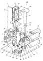
図1、2に示すように、ボンディング装置100は、架台1と、架台1に設けられた一対の送りローラ2a,2bと、送りローラ駆動手段としてのローラ駆動モータ3と、第1ヒータ4により加熱される熱板5と、第2ヒータ6により加熱された空気を送気する送風機7と、送風機7から送られてきた熱風を送りローラ2a,2bにより送られる布及びテープに向けて吹き付ける送風ノズル8と、送風ノズル8をボンディング装置100の上下方向に沿って昇降させるノズル駆動手段としてのノズル昇降装置9と、熱板5の温度を検出する熱板温度センサ10と、送風ノズル8から排出される熱風(空気)の温度を検出する送気温度センサ11と、各部の駆動を制御する制御装置30と、を備えている。An embodiment of a bonding apparatus will be described with reference to the drawings.
(Configuration of bonding equipment)
As shown in FIGS. 1 and 2, the
(架台)
架台1は、設置面を有する底板1aと、底板1aに立設された壁板1bと、を備えている。壁板1bは、底板1aの上面に対して直角に設けられている。(Frame)
The
(送りローラ、送りローラ駆動手段)
送りローラ2a,2bは、上下方向に並ぶように架台1の下側に設けられている。送りローラ2a,2bは、共に回転軸が底板1aの上面に沿った方向に沿うように配置されている。下送りローラ2aは、底板1aに設けられたブラケット20aに支持されている。下送りローラ2aは、底板1aに設けられたローラ駆動モータ3aにより軸回りに回転自在とされている。上送りローラ2bは、ブラケット20bに回転自在に支持されている。上送りローラ2bは、架台1に設けられたローラ駆動モータ3bにより軸回りに回転自在とされている。下送りローラ2aと上送りローラ2bとは互いに逆回りに回転するように各ローラ駆動モータ3a,3bが駆動する。下送りローラ2aと上送りローラ2bは、布の厚さよりも小さい間隔を有する、又は回転に支障がない程度に接するように配置されている。この間に布及びテープを送り込むことにより、布及びテープを重ねて送りつつテープを布に接着することができる。また、布及びテープが送り込まれる位置と同じ高さには、布を載置する布台22が設けられている。布台22には、下送りローラ2aの上部(上送りローラ2bとの対向部)との接触を避けるように形成されている。
上送りローラ2bは、ブラケット20bに連結されたローラ昇降装置としてのエアシリンダ23により、上下方向に移動自在とされている。これにより、二つのローラ2a,2b間の間隔を布の厚さに応じて調節することができる。エアシリンダ23は、支持部材等を介して壁板1bに設けられている。(Feed roller, feed roller drive means)
The
The
(熱板、第1ヒータ)
熱板5は、一方向に延びるように形成された板材であり、熱伝導性の高い材料から形成されている。熱板5は、送りローラ2a,2bよりも手前側となるテープの搬送経路上に設けられている。熱板5は、その長手方向が搬送経路に沿うように配置されている。具体的には、テープは、送りローラ2a,2bの上方に配置された張力付与装置12から送られてくるので、熱板5の長手方向は上下方向に沿うように架台1に配置されている。熱板5の裏面には、電源に接続され、通電により発熱する第1ヒータ4が取り付けられている。すなわち、第1ヒータ4への通電により、その熱が熱板5に伝達され、熱板5が加熱される仕組みとなっている。熱板5は、送りローラ2a,2bでテープを布に接着する前の段階でテープを加熱することにより、送りローラ2a,2bでの布への接着を容易に行うためのものである。従って、熱板5によるテープの加熱は、後述する送風機7からの熱風による加熱に比べて弱く、加熱温度も低い。
熱板5及び第1ヒータ4は、架台1に固定されている。熱板5は、送風ノズル8aの昇降する方向に長手方向が沿うように配置され、送風ノズル8aの上昇により、送風ノズル8aが熱板5に対向するように配置されている。
第1ヒータ4に接続されている電源は、制御装置30に接続されており、制御装置30により通電の制御が行われる。(Hot plate, 1st heater)
The
The
The power source connected to the
(送風機、第2ヒータ、送風ノズル)
送風機7は、底板1aに立設された土台に固定されている。送風機7は、二つ設けられており、一つの送風機7aは、布の上方側から熱風を吹き付ける送風ノズル8aに接続されており、もう一つの送風機7bは、布の下方側から熱風を吹き付ける送風ノズル8bに接続されている。送風機7aと送風ノズル8aは、可撓性を有するエア管71aにより接続され、送風機7aからの空気を送風ノズル8aから排出することができる。送風機7bと送風ノズル8bは、可撓性を有するエア管71bにより接続され、送風機7bからの空気を送風ノズル8bから排出することができる。送風ノズル8aは、ノズル昇降装置9の支持板96に固定されている。送風ノズル8bは、架台1の底板1aに固定されている。
送風機7a,7bには、それぞれ内部の空気を加熱する第2ヒータ6a,6b(図3参照)が設けられている。送風機7a,7bは、第2ヒータ6a,6bで加熱された空気を内蔵されたファンにより送風ノズル8a,8bに向けて排出し、送風ノズル8a,8bからは熱風が排出される。この熱風によりテープが溶融され、布に接着することができる。
ここで、第2ヒータ6a,6bは、第1ヒータ4により加熱される熱板5よりも高温となるように周囲の空気を加熱する。従って、送風ノズル8a,8bから排出される熱風は、熱板5よりも高温となっている。(Blower, second heater, blower nozzle)
The blower 7 is fixed to a base erected on the
The
Here, the
(ノズル昇降装置)
ノズル昇降装置9は、送風ノズル8aを上下方向に沿って昇降させるものである。ノズル昇降装置9は、エアシリンダ91と、軸受92と、ブラケット93と、連結板94と、断熱材95と、支持板96と、支持台97と、を備えている。
エアシリンダ91は、そのピストンロッド91aが下方に向けて進退するように架台1に取り付けられている。軸受92は架台1に設けられており、エアシリンダ91のピストンロッド91aが軸方向に移動自在に支持されている。
ブラケット93はピストンロッド91aの先端に取り付けられている。ブラケット93には、連結板94が連結されている。連結板94には、送風ノズル8aからの熱がエアシリンダ91に伝達するのを防止するための板状の断熱材95が連結されている。断熱材95には、上下方向に延びる支持板96が連結されている。支持板96には、エア管71aからの熱風を取り込むと共にその熱風を送風ノズル8aに流し、送風ノズル8aを支持する支持台97が止めねじ等により取り付けられている。支持板96には、送風ノズル8aも止めねじ等により取り付けられている。
このような構成を採用しているので、エアシリンダ91のピストンロッド91aが上下方向に沿って進退すると、ピストンロッド91aから先端側に接続されているブラケット93、連結板94、断熱材95、支持板96、支持台97、送風ノズル8aも上下方向に沿って移動する。
送風ノズル8aの昇降により、送風ノズル8aは、熱板5に対向する位置と送りローラ2a,2bに対向する位置との間で移動可能となる。(Nozzle lifting device)
The nozzle raising / lowering device 9 raises / lowers the blowing
The
The
Since such a configuration is adopted, when the
By raising and lowering the
(センサ)
図3に示すように、熱板5には、熱板温度センサ10が設けられている。熱板温度センサ10は、制御装置30に接続されており、熱板5の温度情報が制御装置30に送信される。
送風ノズル8aには、送気温度センサ11が設けられている。送気温度センサ11は、制御装置30に接続されており、送風ノズル8aから送気される熱風の温度情報が制御装置30に送信される。(Sensor)
As shown in FIG. 3, the
An air
(張力付与装置)
図1、2に示すように、架台1の壁板1bの上側には、テープが弛まないように一定の張力を付与する張力付与装置12が設けられている。
張力付与装置12は、テープを挟み込んで送る二つのテープローラ12a,12bと、これらのテープローラ12a,12bを支持する土台12cと、一方のテープローラ12aを軸回りに回転させる駆動源となるテープローラ用モータ12dと、を備えている。
テープローラ12a,12bは、上下方向に並ぶように土台12cに回転自在に設けられている。壁板1bには、土台12c及びテープローラ用モータ12dが設けられている。
テープローラ12a,12bでテープを挟持しつつ、弛みをしめる方向に回転することでテープに適度な張力を付与し、常に張った状態でテープを送りローラ2a,2bに送ることができる。(Tensioning device)
As shown in FIGS. 1 and 2, a
The
The
By holding the tape between the
(制御装置)
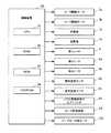
図3に示すように、制御手段としての制御装置30は、各モータの駆動制御、各ヒータの通電制御、送風機7a,7bの駆動制御(送風制御)を行う。
制御装置30は、制御プログラムやデータに基づいて演算処理を行い、上記の各制御を行うCPU31と、ボンディング処理を実行するためのプログラムや各種の設定入力を行うためのプログラムが記憶されたROM33と、CPU31の演算処理の作業場となるRAM32と、書き換え可能なデータや随時変更可能な設定情報が記憶可能とされたEEPROM34と、を備えている。
ROM33には、CPU31によって実行されることにより、熱板5及び送風機7a,7bから送気される空気の温度を下げる際に、送気温度センサ11により検出された空気の温度が熱板温度センサ10により検出された熱板5の温度よりも低温になった場合に、ノズル駆動装置9のエアシリンダ91を駆動させて送風ノズル8aを熱板5と対向する位置まで移動させる機能を実現する冷却制御プログラムが記憶されている。
ROM33には、CPU31によって実行されることにより、熱板5及び送風機7a,7bから送気される空気の温度を上げる際に、送気温度センサ11により検出された空気の温度が熱板温度センサ10により検出された熱板5の温度よりも高温になった場合に、ノズル駆動装置9のエアシリンダ91を駆動させて送風ノズル8aを熱板5と対向する位置まで移動させる機能を実現する加熱制御プログラムが記憶されている。(Control device)
As shown in FIG. 3, the
The
In the
In the
EEPROM34には、送風ノズル8aにより熱板5の加熱補助を行うか否かを判断する閾値となる熱板5と送風機7aから送気される空気の温度差が温度差設定情報として記憶されている。すなわち、EEPROM34は、記憶手段として機能する。
ROM33には、CPU31に実行されることにより、熱板5及び送風機7a,7bから送気される空気の温度を上げる際に、熱板5と送風機7aから送気される空気との温度差がEEPROM34に記憶された温度差よりも大きくなった場合に、ノズル駆動装置9のエアシリンダ91を駆動させて送風ノズル8aを熱板5と対向する位置まで移動させる機能を実現する加熱補助プログラムが記憶されている。
ROM33には、CPU31に実行されることにより、熱板5と送風機7aから送気される空気との温度差がEEPROM34に記憶された温度差よりも大きくなった場合に、ノズル駆動装置9を駆動させて送風ノズル8aを熱板5と対向する位置まで移動させて熱板5を加熱したときの熱板5及び送風機7aから送気される空気が所定の温度に到達するまでの時間と、ノズル駆動装置9を駆動させることなく熱板5及び送風機7aから送気される空気が所定の温度に到達するまでの時間のうち、少ない方の時間を判断する機能を実現する判断プログラムが記憶されている。すなわち、CPU31が判断プログラムを実行することにより、制御装置30は判断手段として機能する。なお、制御装置30がノズル駆動装置9を駆動させて送風ノズル8aを上昇させるか否かについては、EEPROM34にその算出式等のデータが記憶されているため、CPU31が熱板5及び熱風がそれぞれ設定された温度に到達するまでの時間を算出することができる。
ROM33には、CPU31に実行されることにより、CPU31による判断プログラムの実行により判断された少ない時間の方に合わせてノズル駆動装置9の駆動の有無を決定する機能を実現する決定プログラムが記憶されている。すなわち、CPU31が決定プログラムを実行することにより、制御装置30は決定手段として機能する。
制御装置30には、ローラ駆動モータ3a,3bと、送風機7a,7bと、第1ヒータ4と、第2ヒータ6a,6bと、熱板温度センサ10と、送気温度センサ11と、ノズル駆動装置9のエアシリンダ91と、ローラ昇降装置23と、テープローラ用モータ12dと、が接続されている。In the
The
The
The
The
(冷却時の制御)
熱板5及び送風ノズル8aの設定温度を下げる場合のボンディング装置100の動作について説明する。なお、変更された設定温度は、EEPROM34に記憶される。
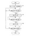
図4に示すように、熱板5及び送風ノズル8aの設定温度を下げる場合には、CPU31は、第1ヒータ4及び第2ヒータ6a,6bへの通電を停止させる(ステップS1)。このとき、送風機7aの送風は継続する。これにより、熱板5は自然放熱で温度が下がり、送風ノズル8aは送風機7aの風が冷却風として機能して温度が下がる。
次いで、CPU31は、熱板温度センサ10と送気温度センサ11により検出された温度を比較し、送気温度センサ11により検出された空気の温度が熱板温度センサ10により検出された熱板5の温度よりも低温になったか否かを判断する(ステップS2)。
ステップS2において、CPU31は、送気温度センサ11により検出された空気の温度が熱板温度センサ10により検出された熱板5の温度よりも低温になったと判断した場合(ステップS2:YES)、CPU31は、冷却制御プログラムを実行することにより、ノズル駆動装置9のエアシリンダ91を駆動させて送風ノズル8aを熱板5と対向する位置まで移動(上昇)させる(ステップS3)。これにより、熱板5を早急に冷却することができる。(Control during cooling)
The operation of the
As shown in FIG. 4, when lowering the set temperature of the
Next, the
In step S2, the
CPU31は、熱板温度センサ10と送気温度センサ11により検出された温度を比較し、熱板温度センサ10により検出された熱板5の温度が送気温度センサ11により検出された空気の温度に到達したか否かを判断する(ステップS4)。
ステップS4において、CPU31は、熱板温度センサ10により検出された熱板5の温度が送気温度センサ11により検出された空気の温度に到達したと判断した場合(ステップS4:YES)、CPU31は、ノズル駆動装置9のエアシリンダ91を駆動させて送風ノズル8aを送りローラ2a,2bと対向する位置まで移動(下降)させる(ステップS5)。
次いで、CPU31は、熱板5及び送風ノズル8aからの熱風の温度がEEPROM34に記憶された変更後の設定温度に到達したか否かを判断する(ステップS6)。
ステップS6において、CPU31は、熱板5及び送風ノズル8aからの熱風の温度がEEPROM34に記憶された変更後の設定温度に到達したと判断した場合(ステップS6:YES)、本処理を終了させる。一方、CPU31は、熱板5及び送風ノズル8aからの熱風の温度がEEPROM34に記憶された変更後の設定温度に到達していないと判断した場合(ステップS6:NO)、CPU31は、ステップS2の処理に戻る。The
In step S4, when the
Next, the
In step S6, when the
(加熱時の制御)
熱板5及び送風ノズル8aの温度を上げる場合のボンディング装置100の動作について説明する。なお、変更された設定温度は、EEPROM34に記憶される。
図5に示すように、熱板5及び送風ノズル8aの設定温度を上げる場合には、CPU31は、第1ヒータ4及び第2ヒータ6a,6bへの通電量を大きくする(ステップS11)。これにより、熱板5及び送風ノズル8aからの熱風の温度は上昇する。
次いで、CPU31は、熱板温度センサ10と送気温度センサ11により検出された温度を比較し、送気温度センサ11により検出された空気の温度が熱板温度センサ10により検出された熱板5の温度よりも高温になったか否かを判断する(ステップS12)。
ステップS12において、CPU31は、送気温度センサ11により検出された空気の温度が熱板温度センサ10により検出された熱板5の温度よりも高温になったと判断した場合(ステップS12:YES)、CPU31は、加熱制御プログラムを実行することにより、ノズル駆動装置9のエアシリンダ91を駆動させて送風ノズル8aを熱板5と対向する位置まで移動(上昇)させる(ステップS13)。これにより、熱板5を早急に加熱することができる。(Control during heating)
The operation of the
As shown in FIG. 5, when raising the set temperature of the
Next, the
In step S12, the
CPU31は、熱板温度センサ10と送気温度センサ11により検出された温度を比較し、熱板温度センサ10により検出された熱板5の温度が送気温度センサ11により検出された空気の温度に到達したか否かを判断する(ステップS14)。
ステップS14において、CPU31は、熱板温度センサ10により検出された熱板5の温度が送気温度センサ11により検出された空気の温度に到達したと判断した場合(ステップS14:YES)、CPU31は、ノズル駆動装置9のエアシリンダ91を駆動させて送風ノズル8aを送りローラ2a,2bと対向する位置まで移動(下降)させる(ステップS15)。
次いで、CPU31は、熱板5及び送風ノズル8aからの熱風の温度がEEPROM34に記憶された変更後の設定温度に到達したか否かを判断する(ステップS16)。
ステップS16において、CPU31は、熱板5及び送風ノズル8aからの熱風の温度がEEPROM34に記憶された変更後の設定温度に到達したと判断した場合(ステップS16:YES)、本処理を終了させる。一方、CPU31は、熱板5及び送風ノズル8aからの熱風の温度がEEPROM34に記憶された変更後の設定温度に到達していないと判断した場合(ステップS16:NO)、CPU31は、ステップS12の処理に戻る。The
In step S14, when the
Next, the
In step S16, if the
(熱板と送風ノズルからの熱風の温度差を用いた加熱制御)
次に、熱板5の温度と送風ノズル8aからの熱風の温度差を利用して、短時間で効率よく熱板5及び熱風の加熱を行う場合の制御について説明する。
これは、図6に示すように、熱風よりも熱板5の方が設定温度が低いにもかかわらず設定温度に到達するまでの加熱時間がかかるため、熱風の加熱時間が多少長くなっても、熱板5の加熱時間を短縮し、ボンディング装置100全体として加熱時間を短縮するためのものである。
図7に示すように、熱板5及び送風ノズル8aの設定温度を上げる場合には、CPU31は、第1ヒータ4及び第2ヒータ6a,6bへの通電量を大きくする(ステップS21)。これにより、熱板5及び送風ノズル8aからの熱風の温度は上昇する。
次いで、CPU31は、熱板温度センサ10により検出された温度と送気温度センサ11により検出された温度の温度差を算出し、算出された温度差がEEPROM34に記憶された温度差以上であるか否かを判断する(ステップS22)。(Heating control using temperature difference between hot air from hot plate and blower nozzle)
Next, control in the case where the
This is because, as shown in FIG. 6, since the
As shown in FIG. 7, when raising the set temperature of the
Next, the
ステップS22において、CPU31は、算出された温度差がEEPROM34に記憶された温度差以上であると判断した場合(ステップS22:YES)、CPU31は、判断プログラムを実行することにより、送風ノズル8aを移動させて熱板5に吹き付けた方が熱板5及び熱風の設定温度への到達が早く終わるか否かを判断し、CPU31による決定プログラムの実行により、ノズル駆動装置9の駆動の有無を決定する(ステップS23)。
ステップS23において、CPU31は、送風ノズル8aを移動させて熱板5に吹き付けた方が熱板5及び熱風の設定温度への到達が早く終わると判断した場合には、ノズル駆動装置9を移動させると決定されるため(ステップS23:YES)、CPU31は、加熱補助プログラムを実行することにより、ノズル駆動装置9のエアシリンダ91を駆動させて送風ノズル8aを熱板5と対向する位置まで移動(上昇)させる(ステップS24)。これにより、熱板5を早急に加熱することができる。一方、CPU31は、送風ノズル8aを移動させない方が熱板5及び熱風の設定温度への到達が早く終わると判断した場合には、ノズル駆動装置9を移動させないと決定されるため(ステップS23:NO)、CPU31は、後述するステップS27の処理に移る。In step S22, when the
In step S23, the
CPU31は、熱板温度センサ10と送気温度センサ11により検出された温度を比較し、熱板温度センサ10により検出された熱板5の温度が送気温度センサ11により検出された空気の温度に到達したか否かを判断する(ステップS25)。
ステップS25において、CPU31は、熱板温度センサ10により検出された熱板5の温度が送気温度センサ11により検出された空気の温度に到達したと判断した場合(ステップS25:YES)、CPU31は、ノズル駆動装置9のエアシリンダ91を駆動させて送風ノズル8aを送りローラ2a,2bと対向する位置まで移動(下降)させる(ステップS26)。
次いで、CPU31は、熱板5及び送風ノズル8aからの熱風の温度がEEPROM34に記憶された変更後の設定温度に到達したか否かを判断する(ステップS27)。
ステップS27において、CPU31は、熱板5及び送風ノズル8aからの熱風の温度がEEPROM34に記憶された変更後の設定温度に到達したと判断した場合(ステップS27:YES)、本処理を終了させる。一方、CPU31は、熱板5及び送風ノズル8aからの熱風の温度がEEPROM34に記憶された変更後の設定温度に到達していないと判断した場合(ステップS27:NO)、CPU31は、ステップS22の処理に戻る。The
In step S25, if the
Next, the
In step S27, if the
具体的には、図8に示すように、熱板5と熱風の温度上昇率は熱風の方が高いため、両者の温度差は時間の経過と共に大きくなっていく(図8のグラフにおける区間D1)。そして、熱板5と熱風の温度差がEEPROM34に記憶された温度差Hよりも大きくなると、送風機7aが駆動して送気するので、送気温度センサ11の温度上昇率は下がる。一方、熱板5は送風機7aからの送気により熱風が吹き付けられて温度上昇率が上がる(図8のグラフにおける区間D2)。
やがて、熱板5と熱風の温度が一致すると、送風機7aによる送風が停止され、送風ノズル8aは熱板5から外れる。これにより、区間D1と同様、熱板5及び熱風はそれぞれ加熱される。以降、熱板5及び熱風がそれぞれの設定温度になるまで上記の駆動制御が繰り返される。
このような手法を採用することで、図8に示すように、熱板5の加熱時間を短縮することができる。Specifically, as shown in FIG. 8, since the temperature rise rate of the
Eventually, when the temperature of the
By adopting such a method, the heating time of the
(発明の実施形態の効果)
ボンディング装置100によれば、送風ノズル8aから送気される空気の温度が熱板5の温度よりも低くなったときに、その空気を熱板5に当てることができる。そのため、熱板5の温度を所定の温度に下げるまでに自然放熱で下げる場合よりも早い時間で下げることができる。
よって、冷却に時間のかかる熱板5の温度をより早く下げることができるので、次の作業までに必要な冷却時間を短縮することができ、作業効率を向上することができる。(Effect of the embodiment of the invention)
According to the
Therefore, since the temperature of the
また、送風ノズル8aから送気される空気の温度が熱板5の温度よりも高くなったときに、その空気を熱板5に当てることができる。そのため、熱板5の温度を所定の温度に上げるまでに熱板5を第1ヒータ4だけで加熱する場合に比べて早い時間で上げることができる。
よって、加熱に時間のかかる熱板の温度をより早く上げることができるので、次の作業までに必要な加熱時間を短縮することができ、作業効率を向上することができる。Further, when the temperature of the air supplied from the blowing
Therefore, since the temperature of the hot plate which takes time for heating can be increased more quickly, the heating time required until the next operation can be shortened, and the working efficiency can be improved.
また、第2ヒータ6a,6bにより加熱される空気の方が第1ヒータ4により加熱される熱板5よりも早く温度が上昇するが、その温度差がEEPROM34に記憶された温度差よりも大きくなると、送風ノズル8aを移動させて熱板5よりも高温の熱風を熱板5に当てることができる。
よって、加熱に時間のかかる熱板5の温度をより早く上げることができるので、次の作業までに必要な加熱時間を短縮することができ、作業効率を向上することができる。The temperature of the air heated by the
Therefore, since the temperature of the
また、ノズル駆動装置9の駆動は、判断プログラムの実行による判断に基づき決定プログラムの実行により決定される。そのため、制御装置30は、常に時間がかからない方法で熱板5及び熱風の加熱補助をするので、次の作業までに必要な加熱時間を短縮することができ、作業効率を向上することができる。 Further, the driving of the nozzle drive device 9 is determined by executing the determination program based on the determination made by executing the determination program. Therefore, since the
なお、本発明は上記実施形態に限られるものではない。例えば、二つの送りローラ2a,2bは、それぞれ個別のローラ駆動モータ3a,3bにより駆動するように構成されているが、少なくとも一方のローラを駆動させることにより、他方のローラを布との摩擦により共回りさせるように構成してもよい。
また、熱板5の加熱補助において、温度差を基準として送風ノズル8aを移動させるのではなく、加熱からの経過時間を基準として送風ノズル8aを移動させるようにしてもよい。The present invention is not limited to the above embodiment. For example, the two
Further, in the heating assist of the
2a 下送りローラ(送りローラ)
2b 上送りローラ(送りローラ)
3a ローラ駆動モータ(送りローラ駆動手段)
3b ローラ駆動モータ(送りローラ駆動手段)
4 第1ヒータ
5 熱板
6a 第2ヒータ
6b 第2ヒータ
7a 送風機
7b 送風機
8a 送風ノズル
8b 送風ノズル
9 ノズル駆動装置(ノズル駆動手段)
10 熱板温度センサ
11 送気温度センサ
30 制御装置(制御手段、判断手段、決定手段)
34 EEPROM(記憶手段)
91 エアシリンダ2a Bottom feed roller (feed roller)
2b Top feed roller (feed roller)
3a Roller drive motor (feed roller drive means)
3b Roller drive motor (feed roller drive means)
4
10 hot
34 EEPROM (storage means)
91 Air cylinder
Claims (4)
Translated fromJapanese前記一対の送りローラのうち、少なくとも一方を回転させて前記テープ及び布の送り動作をさせる送りローラ駆動手段と、
電源に接続され、通電により発熱する第1ヒータと、
前記テープの搬送経路上における前記一対の送りローラよりも手前側に設けられ、前記第1ヒータの発熱により加熱されて前記テープを加熱する熱板と、
電源に接続され、通電により発熱する第2ヒータを有し、前記第2ヒータにより前記熱板よりも高温に加熱された空気を送気する送風機と、
前記送風機に接続され、前記送風機から送気された空気を前記一対の送りローラによる布及びテープの送り部分に吹き付ける送風ノズルと、
前記第1ヒータと前記第2ヒータへの通電、及び前記送風機の送気を制御する制御手段と、を備え、
前記第1ヒータの加熱により前記熱板に接触する前記テープを加熱し、前記送風機から送気される空気を布及びテープに送ることでテープを溶融して布に接着するボンディング装置において、
前記熱板の温度を検出する熱板温度センサと、
前記送風ノズルから送気される空気の温度を検出する送気温度センサと、
前記送風ノズルを前記熱板と対向する位置と前記一対の送りローラによる布及びテープの送り部分との間で移動させるノズル駆動手段と、
前記熱板及び前記送風機から送気される空気の温度を下げる際に、前記送気温度センサにより検出された空気の温度が前記熱板温度センサにより検出された前記熱板の温度よりも低温になった場合に、前記制御手段は、前記ノズル駆動手段を駆動させて前記送風ノズルを前記熱板と対向する位置まで移動させることを特徴とするボンディング装置。A pair of feed rollers that feed the fabric and the tape that adheres to the fabric in an overlapping manner;
Feed roller driving means for rotating at least one of the pair of feed rollers to feed the tape and cloth;
A first heater connected to a power source and generating heat when energized;
A heating plate that is provided on the near side of the pair of feed rollers on the transport path of the tape and is heated by the heat generated by the first heater to heat the tape;
A blower that is connected to a power source and has a second heater that generates heat when energized, and that feeds air heated to a higher temperature than the hot plate by the second heater;
A blower nozzle that is connected to the blower and blows the air fed from the blower to the cloth and tape feed portions of the pair of feed rollers;
Control means for controlling energization to the first heater and the second heater, and air supply of the blower,
In the bonding apparatus that heats the tape in contact with the hot plate by the heating of the first heater, melts the tape by sending air sent from the blower to the cloth and the tape, and bonds the tape to the cloth.
A hot plate temperature sensor for detecting the temperature of the hot plate;
An air supply temperature sensor for detecting the temperature of air supplied from the blow nozzle;
Nozzle driving means for moving the blowing nozzle between a position facing the hot plate and a feeding portion of the cloth and tape by the pair of feeding rollers;
When lowering the temperature of the air supplied from the hot plate and the blower, the temperature of the air detected by the air supply temperature sensor is lower than the temperature of the hot plate detected by the hot plate temperature sensor. When it becomes, the said control means drives the said nozzle drive means, and moves the said ventilation nozzle to the position facing the said hot plate, The bonding apparatus characterized by the above-mentioned.
前記熱板及び前記送風機から送気される空気の温度を上げる際に、前記熱板と前記送風機から送気される空気との温度差が前記記憶手段に記憶された温度差よりも大きくなった場合に、前記制御手段は、前記ノズル駆動手段を駆動させて前記送風ノズルを前記熱板と対向する位置まで移動させることを特徴とする請求項1に記載のボンディング装置。Storage means for storing a temperature difference between the hot plate serving as a threshold for determining whether or not to assist heating of the hot plate by the blow nozzle and air sent from the blower;
When raising the temperature of the air sent from the hot plate and the blower, the temperature difference between the hot plate and the air sent from the blower became larger than the temperature difference stored in the storage means. 2. The bonding apparatus according toclaim 1 , wherein the control unit drives the nozzle driving unit to move the blower nozzle to a position facing the hot platen.
前記判断手段により判断された少ない時間の方に合わせて前記ノズル駆動手段の駆動の有無を決定する決定手段と、
を備えることを特徴とする請求項3に記載のボンディング装置。When the temperature difference between the hot plate and the air sent from the blower is larger than the temperature difference stored in the storage unit, the nozzle driving unit is driven to connect the blow nozzle to the hot plate. The time until the air sent from the hot plate and the blower reaches a predetermined temperature when the hot plate is heated by moving to the opposite position, and the heat without driving the nozzle driving means. Judgment means for judging the smaller time among the time until the air sent from the plate and the blower reaches a predetermined temperature;
Determining means for determining whether or not the nozzle driving means is driven in accordance with the less time determined by the determining means;
The bonding apparatus according to claim 3, further comprising:
Priority Applications (2)
| Application Number | Priority Date | Filing Date | Title |
|---|---|---|---|
| JP2009053069AJP5468276B2 (en) | 2009-03-06 | 2009-03-06 | Bonding equipment |
| ITTO2010A000172AIT1398791B1 (en) | 2009-03-06 | 2010-03-05 | GLUING APPLIANCE |
Applications Claiming Priority (1)
| Application Number | Priority Date | Filing Date | Title |
|---|---|---|---|
| JP2009053069AJP5468276B2 (en) | 2009-03-06 | 2009-03-06 | Bonding equipment |
Publications (2)
| Publication Number | Publication Date |
|---|---|
| JP2010203018A JP2010203018A (en) | 2010-09-16 |
| JP5468276B2true JP5468276B2 (en) | 2014-04-09 |
Family
ID=42964776
Family Applications (1)
| Application Number | Title | Priority Date | Filing Date |
|---|---|---|---|
| JP2009053069AExpired - Fee RelatedJP5468276B2 (en) | 2009-03-06 | 2009-03-06 | Bonding equipment |
Country Status (2)
| Country | Link |
|---|---|
| JP (1) | JP5468276B2 (en) |
| IT (1) | IT1398791B1 (en) |
Families Citing this family (7)
| Publication number | Priority date | Publication date | Assignee | Title |
|---|---|---|---|---|
| JP6394186B2 (en)* | 2014-08-28 | 2018-09-26 | ブラザー工業株式会社 | Cloth bonding equipment |
| CN104489985B (en)* | 2014-12-22 | 2016-08-24 | 鲁泰纺织股份有限公司 | Seamless paste folding linkage bonder |
| CN104997221A (en)* | 2015-07-20 | 2015-10-28 | 英商马田纺织品(中国-中山)有限公司 | Belt flanging machine |
| CN105595495B (en)* | 2016-03-22 | 2017-05-03 | 平湖星天阳服饰科技有限公司 | Double-station seamless underwear hot press |
| JP6785574B2 (en)* | 2016-05-10 | 2020-11-18 | Juki株式会社 | Temperature detection device and bonding device |
| CN106963016B (en)* | 2016-12-28 | 2018-06-19 | 常州智谷机电科技有限公司 | Heat sticking machine |
| CN108936926B (en)* | 2018-10-12 | 2024-01-26 | 常州智谷机电科技有限公司 | Strip sticking machine |
Family Cites Families (3)
| Publication number | Priority date | Publication date | Assignee | Title |
|---|---|---|---|---|
| JPS60117360U (en)* | 1984-01-18 | 1985-08-08 | クインライト電子精工株式会社 | Seal tape adhesion device |
| JPS63177992U (en)* | 1987-05-02 | 1988-11-17 | ||
| JP2609275B2 (en)* | 1988-03-26 | 1997-05-14 | 萩原工業株式会社 | Hot air sealer |
- 2009
- 2009-03-06JPJP2009053069Apatent/JP5468276B2/ennot_activeExpired - Fee Related
- 2010
- 2010-03-05ITITTO2010A000172Apatent/IT1398791B1/enactive
Also Published As
| Publication number | Publication date |
|---|---|
| IT1398791B1 (en) | 2013-03-18 |
| ITTO20100172A1 (en) | 2010-09-07 |
| JP2010203018A (en) | 2010-09-16 |
Similar Documents
| Publication | Publication Date | Title |
|---|---|---|
| JP5468276B2 (en) | Bonding equipment | |
| CN100532071C (en) | Engagement device | |
| US20160177501A1 (en) | Method for welding a curved seam | |
| JP2009226755A5 (en) | ||
| AU2004202583B2 (en) | Method and apparatus for heating glass | |
| US20180015676A1 (en) | Method for bonding at least partially overlapping material layers and automatic bonding apparatus for performing the method | |
| JP5251560B2 (en) | Cloth bonding equipment | |
| KR101315176B1 (en) | A profile heating body and hot-melt laminating machine thereof | |
| US6342115B1 (en) | Laminating heating module | |
| US10220635B2 (en) | Printing device and color development controlling method | |
| KR101253307B1 (en) | Direct heating type card lamination apparatus | |
| JP2000006267A (en) | Joining device for foil material and method therefor | |
| JP5468284B2 (en) | Bonding machine | |
| US11613113B2 (en) | Thermal lamination apparatus for manufacturing film-laminated metal plate | |
| JP2014184676A (en) | Liquid discharge device | |
| JP6318435B2 (en) | Reinforcing device for optical fiber connection | |
| JP2001334574A (en) | Roll forming equipment system | |
| KR100765392B1 (en) | Plastic bag manufacturing equipment | |
| KR20160121163A (en) | Plastic welding apparatus using hot wind | |
| JP2013154913A (en) | Heating controller for packaging machine | |
| JP2022057747A (en) | Treatment furnace | |
| KR101421133B1 (en) | Heat Adhesion System And Method For Plastic Element Using Selective Heating | |
| JP2017128056A (en) | Heating device for thermoplastic carbon fiber material | |
| JP2003188524A (en) | Reflow apparatus | |
| TWM526829U (en) | Heater of vamp vacuum forming machine |
Legal Events
| Date | Code | Title | Description |
|---|---|---|---|
| A621 | Written request for application examination | Free format text:JAPANESE INTERMEDIATE CODE: A621 Effective date:20120301 | |
| A977 | Report on retrieval | Free format text:JAPANESE INTERMEDIATE CODE: A971007 Effective date:20130527 | |
| A131 | Notification of reasons for refusal | Free format text:JAPANESE INTERMEDIATE CODE: A131 Effective date:20130604 | |
| A521 | Written amendment | Free format text:JAPANESE INTERMEDIATE CODE: A523 Effective date:20130731 | |
| TRDD | Decision of grant or rejection written | ||
| A01 | Written decision to grant a patent or to grant a registration (utility model) | Free format text:JAPANESE INTERMEDIATE CODE: A01 Effective date:20140114 | |
| A61 | First payment of annual fees (during grant procedure) | Free format text:JAPANESE INTERMEDIATE CODE: A61 Effective date:20140129 | |
| R150 | Certificate of patent or registration of utility model | Ref document number:5468276 Country of ref document:JP Free format text:JAPANESE INTERMEDIATE CODE: R150 Free format text:JAPANESE INTERMEDIATE CODE: R150 | |
| R250 | Receipt of annual fees | Free format text:JAPANESE INTERMEDIATE CODE: R250 | |
| LAPS | Cancellation because of no payment of annual fees |