JP5467756B2 - Endoscope device - Google Patents
Endoscope deviceDownload PDFInfo
- Publication number
- JP5467756B2 JP5467756B2JP2008291846AJP2008291846AJP5467756B2JP 5467756 B2JP5467756 B2JP 5467756B2JP 2008291846 AJP2008291846 AJP 2008291846AJP 2008291846 AJP2008291846 AJP 2008291846AJP 5467756 B2JP5467756 B2JP 5467756B2
- Authority
- JP
- Japan
- Prior art keywords
- illumination light
- brightness
- amount
- light
- series
- Prior art date
- Legal status (The legal status is an assumption and is not a legal conclusion. Google has not performed a legal analysis and makes no representation as to the accuracy of the status listed.)
- Active
Links
- 238000005286illuminationMethods0.000claimsdescription109
- 239000013307optical fiberSubstances0.000claimsdescription20
- 239000000835fiberSubstances0.000claimsdescription17
- 230000007423decreaseEffects0.000claimsdescription15
- 238000000034methodMethods0.000claimsdescription10
- 238000001514detection methodMethods0.000claimsdescription5
- 230000006870functionEffects0.000claimsdescription4
- 238000003384imaging methodMethods0.000claimsdescription2
- 238000011017operating methodMethods0.000claims1
- 235000019557luminanceNutrition0.000description68
- 230000002093peripheral effectEffects0.000description8
- 230000003287optical effectEffects0.000description7
- 238000010586diagramMethods0.000description6
- 210000000056organAnatomy0.000description2
- 230000003247decreasing effectEffects0.000description1
- 230000006866deteriorationEffects0.000description1
- 238000003708edge detectionMethods0.000description1
- 230000008030eliminationEffects0.000description1
- 238000003379elimination reactionMethods0.000description1
- 238000000605extractionMethods0.000description1
- 210000001035gastrointestinal tractAnatomy0.000description1
- 238000013507mappingMethods0.000description1
Images


Classifications
- A—HUMAN NECESSITIES
- A61—MEDICAL OR VETERINARY SCIENCE; HYGIENE
- A61B—DIAGNOSIS; SURGERY; IDENTIFICATION
- A61B1/00—Instruments for performing medical examinations of the interior of cavities or tubes of the body by visual or photographical inspection, e.g. endoscopes; Illuminating arrangements therefor
- A61B1/00002—Operational features of endoscopes
- A61B1/00004—Operational features of endoscopes characterised by electronic signal processing
- A61B1/00009—Operational features of endoscopes characterised by electronic signal processing of image signals during a use of endoscope
- A—HUMAN NECESSITIES
- A61—MEDICAL OR VETERINARY SCIENCE; HYGIENE
- A61B—DIAGNOSIS; SURGERY; IDENTIFICATION
- A61B1/00—Instruments for performing medical examinations of the interior of cavities or tubes of the body by visual or photographical inspection, e.g. endoscopes; Illuminating arrangements therefor
- A61B1/00163—Optical arrangements
- A61B1/00172—Optical arrangements with means for scanning
- A—HUMAN NECESSITIES
- A61—MEDICAL OR VETERINARY SCIENCE; HYGIENE
- A61B—DIAGNOSIS; SURGERY; IDENTIFICATION
- A61B1/00—Instruments for performing medical examinations of the interior of cavities or tubes of the body by visual or photographical inspection, e.g. endoscopes; Illuminating arrangements therefor
- A61B1/04—Instruments for performing medical examinations of the interior of cavities or tubes of the body by visual or photographical inspection, e.g. endoscopes; Illuminating arrangements therefor combined with photographic or television appliances
- A61B1/043—Instruments for performing medical examinations of the interior of cavities or tubes of the body by visual or photographical inspection, e.g. endoscopes; Illuminating arrangements therefor combined with photographic or television appliances for fluorescence imaging
- A—HUMAN NECESSITIES
- A61—MEDICAL OR VETERINARY SCIENCE; HYGIENE
- A61B—DIAGNOSIS; SURGERY; IDENTIFICATION
- A61B1/00—Instruments for performing medical examinations of the interior of cavities or tubes of the body by visual or photographical inspection, e.g. endoscopes; Illuminating arrangements therefor
- A61B1/06—Instruments for performing medical examinations of the interior of cavities or tubes of the body by visual or photographical inspection, e.g. endoscopes; Illuminating arrangements therefor with illuminating arrangements
- A61B1/063—Instruments for performing medical examinations of the interior of cavities or tubes of the body by visual or photographical inspection, e.g. endoscopes; Illuminating arrangements therefor with illuminating arrangements for monochromatic or narrow-band illumination
- A—HUMAN NECESSITIES
- A61—MEDICAL OR VETERINARY SCIENCE; HYGIENE
- A61B—DIAGNOSIS; SURGERY; IDENTIFICATION
- A61B1/00—Instruments for performing medical examinations of the interior of cavities or tubes of the body by visual or photographical inspection, e.g. endoscopes; Illuminating arrangements therefor
- A61B1/06—Instruments for performing medical examinations of the interior of cavities or tubes of the body by visual or photographical inspection, e.g. endoscopes; Illuminating arrangements therefor with illuminating arrangements
- A61B1/0638—Instruments for performing medical examinations of the interior of cavities or tubes of the body by visual or photographical inspection, e.g. endoscopes; Illuminating arrangements therefor with illuminating arrangements providing two or more wavelengths
- A—HUMAN NECESSITIES
- A61—MEDICAL OR VETERINARY SCIENCE; HYGIENE
- A61B—DIAGNOSIS; SURGERY; IDENTIFICATION
- A61B1/00—Instruments for performing medical examinations of the interior of cavities or tubes of the body by visual or photographical inspection, e.g. endoscopes; Illuminating arrangements therefor
- A61B1/06—Instruments for performing medical examinations of the interior of cavities or tubes of the body by visual or photographical inspection, e.g. endoscopes; Illuminating arrangements therefor with illuminating arrangements
- A61B1/0655—Control therefor
- A—HUMAN NECESSITIES
- A61—MEDICAL OR VETERINARY SCIENCE; HYGIENE
- A61B—DIAGNOSIS; SURGERY; IDENTIFICATION
- A61B5/00—Measuring for diagnostic purposes; Identification of persons
- A61B5/0059—Measuring for diagnostic purposes; Identification of persons using light, e.g. diagnosis by transillumination, diascopy, fluorescence
- A61B5/0062—Arrangements for scanning
- A—HUMAN NECESSITIES
- A61—MEDICAL OR VETERINARY SCIENCE; HYGIENE
- A61B—DIAGNOSIS; SURGERY; IDENTIFICATION
- A61B5/00—Measuring for diagnostic purposes; Identification of persons
- A61B5/0059—Measuring for diagnostic purposes; Identification of persons using light, e.g. diagnosis by transillumination, diascopy, fluorescence
- A61B5/0082—Measuring for diagnostic purposes; Identification of persons using light, e.g. diagnosis by transillumination, diascopy, fluorescence adapted for particular medical purposes
- A61B5/0084—Measuring for diagnostic purposes; Identification of persons using light, e.g. diagnosis by transillumination, diascopy, fluorescence adapted for particular medical purposes for introduction into the body, e.g. by catheters
- G—PHYSICS
- G02—OPTICS
- G02B—OPTICAL ELEMENTS, SYSTEMS OR APPARATUS
- G02B23/00—Telescopes, e.g. binoculars; Periscopes; Instruments for viewing the inside of hollow bodies; Viewfinders; Optical aiming or sighting devices
- G02B23/24—Instruments or systems for viewing the inside of hollow bodies, e.g. fibrescopes
- G02B23/2407—Optical details
- G02B23/2461—Illumination
- G02B23/2469—Illumination using optical fibres
- G—PHYSICS
- G02—OPTICS
- G02B—OPTICAL ELEMENTS, SYSTEMS OR APPARATUS
- G02B26/00—Optical devices or arrangements for the control of light using movable or deformable optical elements
- G02B26/08—Optical devices or arrangements for the control of light using movable or deformable optical elements for controlling the direction of light
- G02B26/10—Scanning systems
- G02B26/103—Scanning systems having movable or deformable optical fibres, light guides or waveguides as scanning elements
- H—ELECTRICITY
- H04—ELECTRIC COMMUNICATION TECHNIQUE
- H04N—PICTORIAL COMMUNICATION, e.g. TELEVISION
- H04N23/00—Cameras or camera modules comprising electronic image sensors; Control thereof
- H04N23/56—Cameras or camera modules comprising electronic image sensors; Control thereof provided with illuminating means
- H—ELECTRICITY
- H04—ELECTRIC COMMUNICATION TECHNIQUE
- H04N—PICTORIAL COMMUNICATION, e.g. TELEVISION
- H04N23/00—Cameras or camera modules comprising electronic image sensors; Control thereof
- H04N23/70—Circuitry for compensating brightness variation in the scene
- H04N23/74—Circuitry for compensating brightness variation in the scene by influencing the scene brightness using illuminating means
- H—ELECTRICITY
- H04—ELECTRIC COMMUNICATION TECHNIQUE
- H04N—PICTORIAL COMMUNICATION, e.g. TELEVISION
- H04N23/00—Cameras or camera modules comprising electronic image sensors; Control thereof
- H04N23/50—Constructional details
- H04N23/555—Constructional details for picking-up images in sites, inaccessible due to their dimensions or hazardous conditions, e.g. endoscopes or borescopes
Landscapes
- Health & Medical Sciences (AREA)
- Life Sciences & Earth Sciences (AREA)
- Surgery (AREA)
- Physics & Mathematics (AREA)
- Engineering & Computer Science (AREA)
- Biomedical Technology (AREA)
- Public Health (AREA)
- Veterinary Medicine (AREA)
- Optics & Photonics (AREA)
- Pathology (AREA)
- Biophysics (AREA)
- General Health & Medical Sciences (AREA)
- Animal Behavior & Ethology (AREA)
- Heart & Thoracic Surgery (AREA)
- Medical Informatics (AREA)
- Molecular Biology (AREA)
- Radiology & Medical Imaging (AREA)
- Nuclear Medicine, Radiotherapy & Molecular Imaging (AREA)
- Signal Processing (AREA)
- Multimedia (AREA)
- General Physics & Mathematics (AREA)
- Astronomy & Astrophysics (AREA)
- Endoscopes (AREA)
- Instruments For Viewing The Inside Of Hollow Bodies (AREA)
Description
Translated fromJapanese本発明は、観察対象に対して光を走査させながら撮影する内視鏡装置に関し、特に、観察画像の明るさ調整に関する。 The present invention relates to an endoscope apparatus that captures an image of an observation target while scanning the light, and more particularly to brightness adjustment of an observation image.
内視鏡装置として、CCDなどのイメージセンサの代わりに走査型光ファイバを備えた内視鏡装置が知られている(例えば、特許文献1参照)。そこでは、シングルモード型光ファイバなどの走査型光ファイバがスコープ内に設けられ、その先端部分は、圧電素子などのアクチュエータによって保持される。圧電アクチュエータは、振動振幅の変調および増幅を行いながらファイバ先端部を螺旋状に振動させる(共振させる)。これにより、光ファイバを通った照明光は、観察部位へ向けて螺旋状に放射される。 As an endoscope apparatus, an endoscope apparatus provided with a scanning optical fiber instead of an image sensor such as a CCD is known (for example, see Patent Document 1). There, a scanning optical fiber such as a single-mode optical fiber is provided in the scope, and the tip portion thereof is held by an actuator such as a piezoelectric element. The piezoelectric actuator vibrates (resonates) the tip of the fiber in a spiral shape while modulating and amplifying the vibration amplitude. Thereby, the illumination light which passed through the optical fiber is radiated spirally toward the observation site.
観察部位で反射した光は、イメージファイバを経由してプロセッサに伝送される。プロセッサにはフォトセンサが設けられており、フォトセンサによって画素信号が検出されると、映像信号が生成される。螺旋状の光走査は所定のフレームレートで周期的に行われ、1画面分の画素信号がフレームレートに合わせて順次読み出される。
1フレーム期間における照明光量が観察エリア全体に対して一様である場合、観察画像の一部に、暗部やハレーションといった不適切な明るさ状態が生じやすい。例えば、内視鏡先端部を消化管などの器官内部に沿って撮影すると、奥行きのある器官中心付近の映像が過度に暗くなる一方で周辺部分が過度に明るくなり、ハレーションが発生する。1フレーム期間内での照明光量は観察エリア全体に対して一様であるため、部分的に不適切な明るさ状態を解消するのに全体的な光量調整を行わなければならない。 When the amount of illumination light in one frame period is uniform over the entire observation area, an inappropriate brightness state such as a dark part or halation tends to occur in a part of the observation image. For example, when the distal end portion of the endoscope is photographed along the inside of an organ such as the digestive tract, an image near the organ center with a depth becomes excessively dark while the peripheral portion becomes excessively bright and halation occurs. Since the amount of illumination light within one frame period is uniform over the entire observation area, overall light amount adjustment must be performed in order to eliminate a partially inappropriate brightness state.
また、一様な照明光によって観察すると、輪郭強調などの明るさ補正は、画像処理によって行う必要がある。そのため、信号処理による画質低下を招く恐れがあり、観察画像の高画質維持を妨げる。 When observed with uniform illumination light, brightness correction such as edge enhancement needs to be performed by image processing. For this reason, there is a risk of image quality deterioration due to signal processing, which hinders maintaining high image quality of the observed image.
本発明の内視鏡装置は、照明光量の調整によって観察画像のエリアに応じて調整可能な内視鏡装置であり、照明光を放射する光源と、観察対象に対し、所定時間間隔で照明光を走査させる走査手段と、観察対象からの反射光を受光し、所定時間間隔に合わせて観察画像に応じた一連の画素信号を取得する撮像手段とを備える。 The endoscope apparatus according to the present invention is an endoscope apparatus that can be adjusted according to the area of the observation image by adjusting the amount of illumination light. Scanning means, and imaging means for receiving reflected light from the observation object and acquiring a series of pixel signals corresponding to the observation image at predetermined time intervals.
例えば、R,G,Bの光を照明光として照射するレーザーが光源として設けられ、照明光の出力値を制御する光源駆動部が設けられる。R,G,Bを同時発光にすることによって白色光を照射すればよい。また、走査手段として、走査型光ファイバと、走査型光ファイバの先端部を2次元的に振動させて照明光を走査させるファイバ駆動部を設ければよい。反射光の検出は、例えばスコープ先端部で受光するように構成する。 For example, a laser that irradiates light of R, G, and B as illumination light is provided as a light source, and a light source driving unit that controls an output value of the illumination light is provided. White light may be irradiated by simultaneously emitting R, G, and B. Moreover, what is necessary is just to provide the fiber drive part which scans illumination light by vibrating a scanning optical fiber and the front-end | tip part of a scanning optical fiber two-dimensionally as a scanning means. The reflected light is detected, for example, by receiving light at the distal end of the scope.
本発明の内視鏡装置は、所定時間間隔に合わせて得られる一連の画素信号から順次検出される一連の時系列的な輝度データに基づき、観察画像の明るさを順次調整する明るさ調整手段を備える。例えば、所定のフレームレートに合わせて得られる一連の輝度データに基づき、順次明るさを調整し、輝度データにおいて明るさ調整が必要と判断した場合、次のフレーム期間(走査期間)において照明光量を調整する。 The endoscope apparatus according to the present invention includes a brightness adjustment unit that sequentially adjusts the brightness of an observation image based on a series of time-series luminance data sequentially detected from a series of pixel signals obtained in accordance with a predetermined time interval. Is provided. For example, when the brightness is sequentially adjusted based on a series of luminance data obtained in accordance with a predetermined frame rate, and it is determined that the brightness adjustment is necessary in the luminance data, the illumination light amount is changed in the next frame period (scanning period). adjust.
そして、本発明の明るさ調整手段は、照明光の走査位置(スポット位置)に応じて観察対象に対する照明光量、光強度を調整することを特徴とする。すなわち、走査期間において、照明光量を一様にするだけでなく、時系列的に照明光量を変化させることが可能である。照明光量の調整方法としては、光源からの光の強度を制御し、あるいは絞りなどを設けて時系列的に制御してもよい。 And the brightness adjustment means of this invention adjusts the illumination light quantity and light intensity with respect to an observation object according to the scanning position (spot position) of illumination light, It is characterized by the above-mentioned. That is, in the scanning period, it is possible not only to make the illumination light amount uniform, but also to change the illumination light amount in time series. As a method for adjusting the amount of illumination light, the intensity of light from the light source may be controlled, or may be controlled in time series by providing a diaphragm.
1フレーム/フィールド分の観察画像を得る走査期間において、照明光量をスポット位置に応じて変更可能であり、観察画像の画素ごとに明るさを調整することができる。このような構成により、画像信号処理を行うことなく、観察画像の一部について明るさ補正することができる。 In the scanning period for obtaining an observation image for one frame / field, the amount of illumination light can be changed according to the spot position, and the brightness can be adjusted for each pixel of the observation image. With such a configuration, it is possible to correct the brightness of a part of the observation image without performing image signal processing.
明るさ調整については、ハレーションなどのノイズ除去、特徴抽出など様々な目的に応じて明るさ調整を行えばよい。あるいは、輪郭強調を行うため、観察画像におけるエッジ部分に対して照明光量を調整してもよい。 As for brightness adjustment, brightness adjustment may be performed according to various purposes such as noise removal such as halation and feature extraction. Or in order to perform outline emphasis, you may adjust the illumination light quantity with respect to the edge part in an observation image.
内視鏡作業中の観察画像の明るさ特性を考慮すると、中心付近などの過度に暗い部分の存在、あるいは周辺部分など過度に明るい部分の存在を解消するのが望ましい。そのため、観察画像の中で相対的に暗い画素に応じた走査位置に対し照明光量を増加させ、相対的に明るい画素に応じた走査位置に対し照明光量を低下させるように構成すればよい。 Considering the brightness characteristics of the observation image during the endoscopic operation, it is desirable to eliminate the presence of an excessively dark portion such as the vicinity of the center or the presence of an excessively bright portion such as the peripheral portion. Therefore, what is necessary is just to comprise so that illumination light quantity may be increased with respect to the scanning position according to a relatively dark pixel in an observation image, and illumination light quantity may be reduced with respect to the scanning position according to a relatively bright pixel.
特に、観察画像全体のグレースケールがあまり変化しないように明るさ補正することが望ましく、明るさ調整手段が、全体的輝度レンジを狭めるように各走査位置の照明光量を増加もしくは低減させるのが好ましい。 In particular, it is desirable to correct the brightness so that the gray scale of the entire observation image does not change so much, and it is preferable that the brightness adjustment means increase or decrease the amount of illumination light at each scanning position so as to narrow the overall luminance range. .
また、観察画像全体の明暗の程度を滑らかにするため、観察画像の中でより明るい/暗いエリアほど大きく補正し、全体的に明暗の差が滑らかになるように構成すればよい。例えば、明るさ調整手段は、検出された一連の時系列輝度データの中で相対的に輝度レベルの低い走査位置ほど照明光量を増加させ、相対的に輝度レベルの高い走査位置ほど照明光量を低下させるのがよい。 Further, in order to smooth the degree of light and darkness of the entire observation image, the brighter / darker area in the observation image may be corrected to be larger so that the overall difference in lightness and darkness is smoothed. For example, the brightness adjustment unit increases the amount of illumination light at a scanning position having a relatively low luminance level in the series of detected time-series luminance data, and decreases the amount of illumination light at a scanning position having a relatively high luminance level. It is good to let them.
このような照明光量補正を行うため、各走査位置の照明光量を、検出された輝度レベルと対応する目標輝度レベルとの差に応じた割合だけ増加もしくは減少させるように構成してもよい。 In order to perform such illumination light amount correction, the illumination light amount at each scanning position may be increased or decreased by a proportion corresponding to the difference between the detected luminance level and the corresponding target luminance level.
観察画像の明暗が許容できる場合、光量補正しないのが望ましい。この場合、明るさ調整手段は、観察画像の中で許容上限値、許容下限値の範囲外となる輝度レベルの割合が所定割合を超えている場合、次のフレーム期間において前回の照明光量を補正しないようにすればよい。 If the observation image is light and dark, it is desirable not to correct the amount of light. In this case, the brightness adjustment means corrects the previous illumination light amount in the next frame period when the ratio of the luminance level outside the range of the allowable upper limit value and the allowable lower limit value exceeds the predetermined ratio in the observed image. Do not do that.
本発明の内視鏡明るさ調整装置は、所定時間間隔で照明光を観察対象に対して走査させたときの反射光から得られる一連の画素信号に基づいて、観察画像に応じた一連の輝度データを順次検出する輝度検出手段と、検出される一連の輝度データに基づいて、明るさ補正を必要とする輝度状態であるか否かを判断する判定手段と、明るさ補正を必要とする場合、照明光の走査位置に応じて観察対象に対する照明光量を調整する明るさ調整手段とを備えたことを特徴とする。 The endoscope brightness adjustment apparatus of the present invention is a series of luminances corresponding to an observation image based on a series of pixel signals obtained from reflected light when illumination light is scanned with respect to an observation target at predetermined time intervals. Luminance detection means for sequentially detecting data, determination means for determining whether the brightness state requires brightness correction based on a series of detected brightness data, and when brightness correction is required And brightness adjustment means for adjusting the amount of illumination light with respect to the observation object in accordance with the scanning position of the illumination light.
本発明のプログラムは、所定時間間隔で照明光を観察対象に対して走査させたときの反射光から得られる一連の画素信号に基づいて、観察画像に応じた一連の輝度データを順次検出する輝度検出手段と、検出される一連の輝度データに基づいて、明るさ補正を必要とする輝度状態であるか否かを判断する判定手段と、明るさ補正を必要とする場合、照明光の走査位置に応じて観察対象に対する照明光量を調整する明るさ調整手段とを機能させることを特徴とする。 The program of the present invention is a luminance that sequentially detects a series of luminance data corresponding to an observation image based on a series of pixel signals obtained from reflected light when illumination light is scanned with respect to an observation target at predetermined time intervals. Detection means, determination means for determining whether or not the brightness state requires brightness correction based on a series of detected brightness data, and scanning position of illumination light when brightness correction is required And a brightness adjusting unit that adjusts the amount of illumination light for the observation target according to the function.
本発明の内視鏡明るさ調整方法は、所定時間間隔で照明光を観察対象に対して走査させたときの反射光から得られる一連の画素信号に基づいて、観察画像に応じた一連の輝度データを順次検出し、検出される一連の輝度データに基づいて、明るさ補正を必要とする輝度状態であるか否かを判断し、明るさ補正を必要とする場合、照明光の走査位置に応じて観察対象に対する照明光量を調整することを特徴とする。 The endoscope brightness adjustment method of the present invention is a series of luminances corresponding to an observation image based on a series of pixel signals obtained from reflected light when illumination light is scanned with respect to an observation target at predetermined time intervals. Data is sequentially detected, and based on a series of detected brightness data, it is determined whether or not the brightness state requires brightness correction. When brightness correction is required, the scanning position of the illumination light is determined. Accordingly, the illumination light quantity with respect to the observation target is adjusted.
本発明によれば、観察画像の任意のエリアに対し、画像処理することなく明るさ調整することができる。 According to the present invention, it is possible to adjust the brightness of any area of an observation image without performing image processing.
以下では、図面を参照して本発明の実施形態について説明する。 Hereinafter, embodiments of the present invention will be described with reference to the drawings.
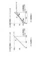
図1は、第1の実施形態である内視鏡装置のブロック図である。図2は、走査光ファイバを模式的に示した図である。 FIG. 1 is a block diagram of an endoscope apparatus according to the first embodiment. FIG. 2 is a diagram schematically showing a scanning optical fiber.
内視鏡装置は、スコープ10とプロセッサ30とを備え、スコープ10には、照明用の光ファイバ(以下、走査型光ファイバという)17と観察対象からの反射光を伝送する光ファイバ(以下、イメージファイバという)14が設けられている。イメージファイバ14の先端部は分岐しており、光学レンズ19の周囲に配置されている。スコープ10はプロセッサ30に着脱自在に接続され、また、プロセッサ30にはモニタ60が接続される。 The endoscope apparatus includes a
プロセッサ30には、R,G,Bの光をそれぞれ発光するレーザー光源20R、20G、20Bが設けられ、レーザードライバ22R、22G、22Bによって駆動される。レーザー光源20R、20G、20BからR,G,Bの光が同時発光し、R,G,Bの光はハーフミラー群24、集光レンズ25によって集光され、白色光として走査型光ファイバ17に入射する。入射した光は、走査型光ファイバ17を通ってスコープ先端部10Tへ送られる。 The
図2に示すように、スコープ先端部10Tには、スコープ先端部10Tから射出する光を走査させるスキャナデバイス(以下、SFEスキャナという)16が設けられている。SFEスキャナ16は、アクチュエータ18備え、スコープ10内に設けられたシングルモード型の走査型ファイバ17は、円筒状アクチュエータ18の軸に挿通されて保持される。 As shown in FIG. 2, the scope
スコープ先端部10Tに固定されたアクチュエータ18は、ピエゾ素子によるチューブ型アクチュエータであり、走査型光ファイバ17の先端部17Aを二次元的に共振させる。すなわち、直交する2方向に沿って所定の共振モードでファイバ先端部17Aを共振させる。アクチュエータ18によってカンチレバー状に支持されるファイバ先端部17Aは、共振に従って先端面17Sの向きを変え、螺旋状に動く。 The
その結果、先端面17Sから射出し、光学レンズ19を通って観察部位Sに到達する光の軌跡PTは、螺旋状走査線になる。螺旋状走査線PTの径方向間隔が密であるため、観察対象Q全体が順に照射されていく。 As a result, the trajectory PT of the light emitted from the distal end surface 17S and reaching the observation site S through the
観察対象Qで反射した光は、イメージファイバ14に入射し、プロセッサ30へ導かれる。イメージファイバ14からの反射光は、光学レンズ26、ハーフミラー群27によってR,G,Bの光に分離され、それぞれフォトセンサ28R、28G、28Bに入射する。フォトセンサ28R、28G、28Bは、それぞれR,G,Bの光をR,G,Bに応じた画素信号に変換する。 The light reflected by the observation object Q enters the
R,G,Bに応じた画素信号は、A/D変換器29R、29G、29Bにおいてデジタル画素信号に変換され、信号処理回路32へ送られる。信号処理回路32では、順次送られてくるR,G,Bのデジタル画素信号と照明光の走査位置とのマッピングにより、画素位置が特定され、1フレーム分のデジタル画素信号が取得される。そして、デジタル画素信号に対してホワイトバランス調整などの画像信号処理が施され、映像信号が生成される。映像信号はエンコーダ37を介してモニタ60に送られ、これにより観察画像がモニタ60に表示される。 Pixel signals corresponding to R, G, and B are converted into digital pixel signals by A /
CPU、ROM、RAMを含むコントローラ40は、プロセッサ30の動作を制御し、ROMには動作制御に関するプログラムが格納されている。コントローラ40は、信号処理回路32、タイミングコントローラ34、レーザードライバ22R、22G、22Bなど各回路へ制御信号を出力する。タイミングコントローラ34は、ドライバ36A、36B、レーザードライバ22R、22G、22B、およびSFEスキャナ16に駆動信号を出力するファイバドライバ36A、36Bに対して同期信号を出力し、ファイバ先端部17Aの振動と発光のタイミングを同期させる。 A
レーザー20R、20G、20Bの出力はレーザードライバ22R、22G、22Bからの駆動信号(電流量)に基づいて調整され、観察対象への照明光量(光強度)が調整される。信号処理回路32では、デジタル画素信号に基づいて輝度信号が生成され、輝度信号がコントローラ40へ送られる。コントローラ40は、輝度信号に基づいて照明光量を調整するため、レーザードライバ22R、22G、22Bに制御信号を出力する。 The outputs of the
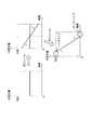
図3は、照明光量のタイミングチャートを示した図である。図4は、照明光量調整による観察画像の画面を示した図である。図3、図4を用いて、照明光量調整について説明する。 FIG. 3 is a diagram showing a timing chart of the illumination light quantity. FIG. 4 is a view showing a screen of an observation image by adjusting the illumination light quantity. The illumination light amount adjustment will be described with reference to FIGS.
図3には、ファイバ先端部17Aの振幅に合わせてレーザー20R、20G、20Bから放射される照明光の光量LM、およびそれによって検出される時系列輝度データPLが図示されている。1フレーム期間中の期間RAでは、ファイバ先端部17Aの2次元振動によって1フレーム分の画素信号が検出される。ファイバ先端部17Aは、その後の期間RBにおいて中心位置へ戻る。 FIG. 3 illustrates the amount of illumination light LM emitted from the
図4(A)には、内視鏡先端部を器官進行方向に沿って向けながら撮影したときの観察画面が示してあり、図3に、1つのフレーム期間(A)において光量LMが一定光量であるときの輝度データPLが時系列的に表されている。ただし、ここでは説明を簡単にするために光量LMを一定としている。また、輝度値は、例えば0〜255の256段階による輝度レベルとして表す。 FIG. 4A shows an observation screen when an image is taken while the distal end portion of the endoscope is directed along the organ advancing direction, and FIG. 3 shows that the light amount LM is a constant light amount in one frame period (A). Luminance data PL at the time of is shown in time series. However, here, the light quantity LM is constant to simplify the description. The luminance value is expressed as a luminance level in 256 levels from 0 to 255, for example.
図4(A)に示す観察画像RIの場合、画面中心から画面周辺部分A2に向けて明るさレベルが増加する。このとき、画面中心付近A1では極端に暗くなる一方、画面の周囲部分A2では、過度な明るさレベルとなってハレーション発生が部分的に生じている。走査線が螺旋状であることから、一連の時系列的な輝度レベルPLにおいて、画面中心付近A1に応じた時間帯に最小輝度レベル付近の輝度値が得られ、周辺部分A2に応じた時間帯では最大輝度レベル付近の輝度値が得られる(図3参照)。 In the case of the observation image RI shown in FIG. 4A, the brightness level increases from the screen center toward the screen peripheral portion A2. At this time, it becomes extremely dark near the center A1 of the screen, whereas in the peripheral portion A2 of the screen, halation occurs partially due to an excessive brightness level. Since the scanning line is spiral, in a series of time-series luminance levels PL, a luminance value near the minimum luminance level is obtained in a time zone corresponding to the vicinity A1 of the screen center, and a time zone corresponding to the peripheral portion A2. Then, a luminance value near the maximum luminance level is obtained (see FIG. 3).
本実施形態では、1フレーム期間に照明光を螺旋状走査させるとき、走査位置(スポット位置)に応じて照明光量を変化させ、観察画像全体の明るさを走査位置ごと、すなわち観察画像の画素ごとに調整する。図3に示すように、次のフレーム期間(B)では、照明光量LMが時系列的に変化し、走査位置(スポット位置)によって異なる。具体的には、画面中心付近A1で相対的に増加し、周辺部分A2、すなわち輝度レベルが高かった方向に向けて照明光量LMを低下させる。 In this embodiment, when the illumination light is spirally scanned in one frame period, the illumination light quantity is changed according to the scanning position (spot position), and the brightness of the entire observation image is changed for each scanning position, that is, for each pixel of the observation image. Adjust to. As shown in FIG. 3, in the next frame period (B), the amount of illumination light LM changes in time series and varies depending on the scanning position (spot position). Specifically, the amount of illumination light LM increases relatively near the center A1 of the screen and decreases toward the peripheral portion A2, that is, the direction in which the luminance level is high.
その結果、フレーム期間(B)において検出される一連の時系列輝度データPLは、輝度レンジが全体的に狭められた結果、明暗の差が過度に大きくならず、観察に支障をきたす暗部、ハレーション部のない適切な明るさの観察画像が得られる。図4(B)には、フレーム期間(B)における光量調整によって得られる観察画像が表されている。 As a result, the series of time-series luminance data PL detected in the frame period (B) has a brightness range that is narrowed as a whole, so that the difference between brightness and darkness does not become excessively large, and dark portions and halation that hinder observation. An observation image having appropriate brightness with no part can be obtained. FIG. 4B shows an observation image obtained by light amount adjustment in the frame period (B).
図5は、コントローラ40によって実行される光量調整処理を示したフローチャートであり、照明光の走査周期に応じて所定の時間間隔で実行される。図6は、光量調整するときの検出輝度レベルと次期フレーム期間における目標輝度レベルとの関係を示した図である。図7は、光量が設定範囲を超えたときの光量調整を示した図である。図5〜図7を用いて、光量調整について説明する。 FIG. 5 is a flowchart showing the light amount adjustment process executed by the
ステップS101では、フラグfH、fLが0に設定される。フラグfH、fLは、光量補正を次のフレーム期間において行うか否かを判断する変数であり、0もしくは1に設定される。フラグfH、fLがともに0の値に設定されると、ステップS102では、前回のフレーム期間における輝度データおよび照明光量データがそれぞれドライバ調整値用メモリ33、画像用メモリ31に格納されているか否かが判断される。データが格納されていない場合、ステップS109へ移る。 In step S101, the flags fH and fL are set to 0. The flags fH and fL are variables for determining whether or not the light amount correction is performed in the next frame period, and is set to 0 or 1. When the flags fH and fL are both set to 0, in step S102, whether or not the luminance data and the illumination light amount data in the previous frame period are stored in the driver adjustment value memory 33 and the
一方、前回のフレーム期間における輝度データおよび照明光量データが保存されていると判断されると、ステップS103に進み、フラグfH、fLのいずれか一方が1であるか否かが判断される。後述するように、光量調整の必要のない状況である場合、フラグfH、fLがともに0に設定され、それ以外の状況、すなわち次回のフレーム期間において光量調整の必要がある場合、フラグfH、fLのいずれか一方が1に設定される。 On the other hand, if it is determined that the luminance data and the illumination light quantity data in the previous frame period are stored, the process proceeds to step S103, and it is determined whether one of the flags fH and fL is 1. As will be described later, when the light amount adjustment is not necessary, the flags fH and fL are both set to 0. When the light amount adjustment is necessary in other situations, that is, in the next frame period, the flags fH and fL. Is set to 1.
ステップS104では、レーザー20R、20G、20Bの照明光量が以下の式に基づいて設定される。Ln+1は、n+1番目のフレームにおける照明光量を表し、Lnは、n番目のフレームにおける照明光量を表す。
Ln+1=Ln−Ln×(Yn−Yn+1)/100
ただし、Yn>Ymax/2
・・・(1)
Ln+1=Ln+Ln×(Yn−Yn+1)/100
ただし、Yn≦Ymax/2
・・・(2)In step S104, the illumination light amounts of the
L n + 1 = L n -L n × (Y n -Y n + 1) / 100
However,Y n> Ymax / 2
... (1)
L n + 1 = L n + L n × (Y n -Y n + 1) / 100
However,Y n ≦Ymax / 2
... (2)
Ynは、n番目のフレームにおいて検出された各走査位置(画素)の輝度レベルを示す。一方、Yn+1は、n+1番目のフレームにおける各画素の目標輝度レベルを示し、以下の式によってYnの関数として表される。
Yn+1=Yn×(3/5)+20 ・・・(3)
Yn represents the brightness level of each scanning position (pixels) detected in the n-th frame. On the other hand, Yn + 1 indicates the target luminance level of each pixel in the (n + 1) th frame, and is expressed as a function of Yn by the following equation.
Yn + 1 = Yn × (3/5) +20 (3)
図6(A)には、光量調整しない場合におけるYn、Yn+1の対応関係がグラフで表されており、縦軸は、n+1番目のフレームに対する目標輝度レベルYn+1の値を表す。ただし、最大輝度レベル値を100%としたときの割合で表している。また、横軸は実際に検出されるn番目の輝度レベルYnをパーセンテージで表している。一方、図6(B)には、光量調整する時のYn、Yn+1の対応関係が表されている。In FIG.6A , the correspondence relationship between Yn and Yn + 1 when the light amount is not adjusted is represented by a graph, and the vertical axis represents the value of the target luminance level Yn + 1 for the (n + 1) th frame. However, it is expressed as a ratio when the maximum luminance level value is 100%. The horizontal axis represents thenth luminance level Yn actually detected as a percentage. On the other hand, FIG. 6B shows the correspondence between Yn and Yn + 1 when adjusting the amount of light.
光量補正しない場合、n+1番目のフレーム期間における目標輝度レベルYn+1は、各画素ともにn番目のフレーム期間における輝度レベルYnと一致する。すなわち、n番目フレームの各画素の輝度レベルYnはそのまま目標輝度レベルYn+1となり、Yn、Yn+1との関係は、直線KLによって表される。When the amount of light is not corrected, the target luminance level Yn + 1 in the (n + 1) th frame period is the same as the luminance level Yn in the nth frame period for each pixel. That is, the brightness level of each pixel of the n-th frameY n intact target luminance levelY n + 1becomes, Yn, the relationship betweenY n + 1 is represented by a straight line KL.
一方、光量補正を行う場合、各画素の輝度レベルYnに応じて次のn+1番目のフレーム期間における照明光量が図6に示すように補正される。(1)、(2)式から明らかなように、輝度レベルYnの大きさによって光量を増加するか減少するか決定される。具体的には、輝度レベルYnが最大輝度レベルYmaxの50%より大きい場合に光量増加、50%以下の場合には光量減少が実行される。On the other hand, when the light quantity correction, illumination light quantity in the next (n + 1) th frame period in accordance with the luminance level Yn of each pixel is corrected as shown in FIG. (1), (2) As apparent from the equation, it is determined whether to decrease or increase the amount of light by the magnitude of the luminance level Yn. Specifically, the amount of light increases when the luminance level Yn is greater than 50% of the maximum luminance level Ymax, the light quantity decreases in the case of 50% or less is executed.
また、光量増加/減少の程度については、輝度レベルYnが高いほど光量減少量を大きくし、輝度レベルYnが低いほど光量増加量を大きくしている。具体的には、(1)、(2)式に示すように、輝度レベルYnと目標輝度レベルYn+1との差に応じた割合だけ光量を増加もしくは減少させる。As for the degree of increase / decrease in the amount of light, the amount of decrease in light amount is increased as the luminance level Yn is higher, and the amount of increase in light amount is increased as the luminance level Yn is lower. Specifically, (1), (2) as shown in the expression increases or decreases the amount of light only a ratio according to the difference between the luminance level Yn and a target luminance level Yn + 1.
さらに、(1)、(2)式に基づく光量補正により、輝度レンジの範囲が狭まる。図6に示す光量補正では、n+1番目フレームにおける目標輝度レベルYn+1の範囲が20%〜80%の範囲に縮小し、グレースケールの具合を変えずに暗部、ハレーション発生部などのエリア発生を防いでいる。Furthermore, the brightness range is narrowed by the light amount correction based on the equations (1) and (2). In the light amount correction shown in FIG. 6, the range of the target luminance level Yn + 1 in the (n + 1) th frame is reduced to a range of 20% to 80%, and the occurrence of areas such as dark portions and halation generation portions is prevented without changing the gray scale condition. It is out.
光量補正は、各走査位置、すなわち各画素に対して実行され、レーザー20R、20G、20Bの射出光量(光強度)が走査位置に合わせて調整される。ステップS104において光量調整が行われると、ステップS105に進む。 The light amount correction is executed for each scanning position, that is, each pixel, and the emitted light amounts (light intensity) of the
ステップS105では、(1)、(2)式に基づいてステップS104で定められた照明光量が上限以下であるか否かが判断される。レーザー20R、20G、20Bの性能から定まる光量上限を超えた値が設定された場合、照明光量は上限値に設定される(S106)。また、ステップS107では、定められた照明光量が下限以上であるか否かが判断される。定められた照明光量が性能から定まる下限より小さい場合、照明光量は下限値に設定される(S108)。 In step S105, it is determined whether or not the amount of illumination light determined in step S104 is equal to or less than the upper limit based on equations (1) and (2). When a value exceeding the upper limit of the light amount determined from the performance of the
図7には、設定される照明光量の変化が図示されている。初めのフレームでは照明光量が一定に定められ、次のフレームでは照明光量が単調減少となるように定められている。すなわち、観察画像の中心ほど光量を増加させるように設定される。そして、次のフレームにおいては、周辺部に向けての光量減少がより大きくなるように定められ、(3)式に基づく光量補正では、中心付近および周辺部分において上限値、下限値を超えてしまう。この場合、限界値を超える範囲においては、上限値、下限値の照明光量が設定される。 FIG. 7 illustrates changes in the set illumination light quantity. In the first frame, the illumination light amount is determined to be constant, and in the next frame, the illumination light amount is determined to monotonously decrease. In other words, the light amount is set to increase toward the center of the observation image. In the next frame, the light amount reduction toward the peripheral portion is determined to be larger, and the light amount correction based on the expression (3) exceeds the upper limit value and the lower limit value in the vicinity of the center and the peripheral portion. . In this case, in the range exceeding the limit value, the illumination light amount of the upper limit value and the lower limit value is set.
各走査位置における照明光量が定められると、ステップS109では、設定された照明光量に基づいてレーザー20R、20G、20Bの出力が制御される。これにより、光ファイバ先端部の振動に合わせながら照明光の光強度が制御される。 When the illumination light amount at each scanning position is determined, in step S109, the outputs of the
ステップS110では、ステップS104で設定された照明光量の走査位置(画素)に応じた出力値がドライバ調整用メモリ32に格納される。それとともに、ステップS104によって設定された照明光量に従って観察画像の各スポットが順番に照明されるのに伴い、各スポットの輝度レベルが順次検出される。検出された1フレーム分の観察画像に応じた一連の輝度レベルデータは、画像用メモリ31に格納される。 In step S110, an output value corresponding to the scanning position (pixel) of the illumination light amount set in step S104 is stored in the
ステップS111では、検出された一連の輝度レベルの中で許容上限値を超えている割合が10%以上であるか否かが判断される。許容上限値は、観察画像の中で観察に支障を来さない明るさの上限値を表す。観察画像の中で許容上限値を超えている画素の割合が10%以上である場合、次のフレーム期間において照明光量を補正する必要があるとみなし、フラグfHが1に設定される(S112)。一方、許容上限値を超えている画素の割合が10%より少ない場合、次回の走査時には光量補正の必要性がないと判断し、フラグfHが0に設定される(S113)。 In step S111, it is determined whether or not the ratio of the detected series of luminance levels exceeding the allowable upper limit value is 10% or more. The allowable upper limit value represents an upper limit value of brightness that does not hinder observation in the observation image. When the ratio of pixels exceeding the allowable upper limit in the observation image is 10% or more, it is considered that the illumination light amount needs to be corrected in the next frame period, and the flag fH is set to 1 (S112). . On the other hand, if the percentage of pixels exceeding the allowable upper limit is less than 10%, it is determined that there is no need for light amount correction at the next scanning, and the flag fH is set to 0 (S113).
ステップS113では、検出された一連の輝度レベルの中で許容下限値を超えている割合が10%以上であり、かつ、ステップS104で設定された照明光量について50%以上の画素(走査位置)が上限を超えていたか否かが判断される。許容下限値は、観察画像の中で観察に支障を来さない明るさの下限値を示す。 In step S113, the ratio of the detected luminance level exceeding the allowable lower limit value is 10% or more, and 50% or more of the pixels (scanning positions) with respect to the illumination light amount set in step S104. It is determined whether or not the upper limit has been exceeded. The allowable lower limit value indicates a lower limit value of brightness that does not interfere with observation in the observation image.
観察画像の中で許容下限値を超えている画素の割合が10%以上であり、かつ、観察画像全体の中で照明光量を補正不可能な割合(画素割合)が50%より少ない場合、次回の走査時に光量補正する必要があると判断し、フラグfLが1に設定される(S115)。一方、許容下限値を超えている画素の割合が10%より少なく、あるいは、照明光量を補正不可能な割合が50%以上である場合、次回の走査時には光量補正の必要性がないと判断し、フラグfHが0に設定される(S116)。 When the ratio of pixels exceeding the allowable lower limit value in the observation image is 10% or more and the ratio (pixel ratio) in which the illumination light quantity cannot be corrected is less than 50% in the entire observation image, the next time It is determined that it is necessary to correct the amount of light during scanning, and the flag fL is set to 1 (S115). On the other hand, if the percentage of pixels exceeding the allowable lower limit is less than 10%, or the percentage that the illumination light quantity cannot be corrected is 50% or more, it is determined that there is no need for light quantity correction at the next scanning. The flag fH is set to 0 (S116).
ステップS117では、観察終了の操作が行われたか否かが判断される。観察終了と判断されると、処理が終了する。 In step S117, it is determined whether or not an observation end operation has been performed. When it is determined that the observation is finished, the process is finished.
このように本実施形態によれば、光ファイバ先端部17Aを周期的に螺旋状に振動させることにより、照明光を時系列的に順次観察画像に照射する。そして、反射光に基づいてシーケンシャルな一連の輝度レベルが検出される。観察画像において過度な暗部、ハレーション部分の存在が所定の許容割合を超えている場合(S111、S113)、次回の光量調整時において光量補正することが決定される(S112、S115)。 Thus, according to the present embodiment, the observation light is sequentially irradiated with illumination light in time series by periodically vibrating the
次の走査時には、明るい輝度レベルをもつ走査位置(画素)ほど光量を減少させ、暗い輝度レベルをもつ走査位置ほど光量を減少させるように照明光量が設定され(S104)、走査位置に応じて(画素ごとに)照明光量が制御される(S109)。 At the next scanning, the amount of illumination light is set so that the amount of light decreases at a scanning position (pixel) having a bright luminance level, and the amount of light decreases at a scanning position having a dark luminance level (S104). The amount of illumination light is controlled for each pixel (S109).
照明光量の出力値については、目標輝度レベルと検出された輝度レベルの差に応じて照明光量の増加もしくは減少量が定められる((1)、(2)式参照)。また、観察画像に対して明るさ調整が必要な状況の場合にのみ、次回のフレーム期間において光量調整が行われる(S103、S111〜S116)。 As for the output value of the illumination light amount, an increase or decrease amount of the illumination light amount is determined according to the difference between the target luminance level and the detected luminance level (see equations (1) and (2)). Further, the light amount adjustment is performed in the next frame period only when the brightness adjustment is necessary for the observation image (S103, S111 to S116).
次に、図8を用いて、第2の実施形態である内視鏡装置について説明する。第2の実施形態では、エッジ強調処理のために照明光量が調整される。それ以外の構成については、実質的に第1の実施形態と同じである。 Next, an endoscope apparatus according to the second embodiment will be described with reference to FIG. In the second embodiment, the amount of illumination light is adjusted for edge enhancement processing. Other configurations are substantially the same as those in the first embodiment.
図8は、照明光量と輝度レベルのタイミングチャートを示した図である。 FIG. 8 shows a timing chart of the illumination light quantity and the luminance level.
図8には、明暗の境界部分となるエッジ部を含む観察画像についての輝度データが表されている。観察画像は、低輝度レベルPのエリアが中心付近に位置し、その周囲には高輝度レベルQをもつエリアが同心状に位置する。低輝度レベルPと高輝度レベルQの境界となるエッジ部Eが検出されると、次のフレーム走査時には、輪郭強調するように照明光量が制御される。具体的には、エッジ部Eに応じた走査位置の前後で光量差を生じさせる。 FIG. 8 shows luminance data regarding an observation image including an edge portion that becomes a boundary portion between light and dark. In the observation image, an area having a low luminance level P is located near the center, and an area having a high luminance level Q is concentrically located around the area. When the edge portion E that is the boundary between the low luminance level P and the high luminance level Q is detected, the amount of illumination light is controlled so as to enhance the outline during the next frame scan. Specifically, a light amount difference is generated before and after the scanning position corresponding to the edge portion E.
その結果、エッジ部における低輝度レベルPと高輝度レベルQとの差がより大きくなり、観察画像の輪郭が強調される。 As a result, the difference between the low luminance level P and the high luminance level Q at the edge portion becomes larger, and the contour of the observation image is emphasized.
本実施形態では、フレームレートに合わせて光量調整を行っているが、2つのフレーム期間で一回の光量調整を行うようにしてもよい。具体的に言えば、第1フレーム期間において光量を一定にすることによって輝度レベルを検出し、次の第2フレーム期間において光量調整を行うように構成する。 In this embodiment, the light amount is adjusted in accordance with the frame rate, but the light amount may be adjusted once in two frame periods. Specifically, the luminance level is detected by making the light amount constant in the first frame period, and the light amount is adjusted in the next second frame period.
明るさ補正については、上述した観察障害部分(ノイズ部)の解消、エッジ検出以外の目的に適用してもよい。また、(3)式以外の方法によって照明光量を補正してもよく、例えばハレーション部分のみ光量減少させるように対象画素(走査位置)のみ光量調整してもよい。 The brightness correction may be applied for purposes other than the above-described observation obstacle portion (noise portion) elimination and edge detection. Further, the illumination light quantity may be corrected by a method other than the expression (3). For example, only the target pixel (scanning position) may be adjusted so that the light quantity is reduced only in the halation portion.
走査型光ファイバ以外の構成によって光走査を行ってもよく、例えばファイバ先端部の光学系によって光を走査させるように構成してもよい。光源は、レーザー以外のランプを使用することが可能である。また、R,G,Bの光ごとに出力を変えるように構成してもよい。 The optical scanning may be performed by a configuration other than the scanning optical fiber. For example, the optical scanning may be performed by an optical system at the tip of the fiber. A lamp other than a laser can be used as the light source. Moreover, you may comprise so that an output may be changed for every R, G, and B light.
10 ビデオスコープ
12 CCD
16 SFEスキャナ
17 走査型光ファイバ
20R、20G、20B レーザー
30 プロセッサ
40 コントローラ
10 Video scope 12 CCD
16
Claims (12)
Translated fromJapanese観察対象に対し、所定のフレームレートで照明光を螺旋状に走査させる走査手段と、
観察対象からの反射光を受光し、前記所定のフレームレートに合わせて観察画像に応じた一連の画素信号を取得する撮像手段と、
前記一連の画素信号に基づいて、1フレーム分の観察画像に応じた一連の輝度データを順次検出する輝度検出手段と、
検出される一連の輝度データに基づき、照明光の走査位置に応じて観察対象に対する照明光量を調整する明るさ調整手段とを備え、
前記明るさ調整手段が、1フレーム期間において検出される一連の輝度データの中で、許容上限値、許容下限値の範囲外となる輝度レベルの割合が所定割合を超えている場合、光量補正することを決定し、次のフレーム期間において、前回のフレーム期間における照明光量を走査位置に応じて補正することを特徴とする内視鏡装置。A light source that emits illumination light;
Scanning means forspirally scanning illumination light at a predeterminedframe rate with respect to the observation target;
An imaging means for receiving reflected light from the observation target, to acquire a set of pixel signals corresponding to the observation image in accordance with thepredetermined frame rate,
Luminance detection means for sequentially detecting a series of luminance data corresponding to an observation image forone frame based on the series of pixel signals;
Brightness adjustment meansfor adjusting the amount of illumination light with respect to the observation object according to the scanning position of the illumination light based on a series of detected luminance data;
The brightness adjustment meanscorrects the amount of light when a ratio of luminance levels outside the allowable upper limit value and the allowable lower limit value exceeds a predetermined ratio in a series of luminance data detected in one frame period. An endoscope apparatus characterized inthat, in the next frame period, the amount of illumination light in the previous frame period is corrected according to the scanning position .
前記光源が、R,G,Bの光を照明光として照射する光源であることを特徴とする請求項1乃至請求項7のいずれかに記載の内視鏡装置。A light source driving unit for controlling the light intensity of the illumination light;
The endoscope apparatus according to claim 1, wherein the light source is a light source that emits R, G, and B light as illumination light.
検出される一連の輝度データに基づいて、明るさ補正を必要とする輝度状態であるか否かを判断する判定手段と、
明るさ補正を必要とする場合、照明光の走査位置に応じて観察対象に対する照明光量を調整する明るさ調整手段とを備え、
前記明るさ調整手段が、次のフレーム期間において、前回のフレーム期間における照明光量を走査位置に応じて補正する
ことを特徴とする内視鏡画像明るさ調整装置。Based on a series of pixel signals obtained from the reflected light when the illumination light is scanned in aspiral manner at a predeterminedframe rate , a series of luminance data corresponding tothe observation image forone frame is sequentially detected. Brightness detecting means for
Determination means for determining whether or not the brightness state requires brightness correction based on a series of detected brightness data;
When brightness correction is required, it comprises a brightness adjustment means for adjusting the amount of illumination light for the observation object according to the scanning position of the illumination light,
The endoscope image brightness adjustment apparatus,wherein the brightness adjustment means corrects the illumination light quantity in the previous frame period in accordance with the scanning position in the next frame period .
所定のフレームレートで照明光を観察対象に対して螺旋状に走査させたときの反射光から得られる一連の画素信号に基づいて、1フレーム分の観察画像に応じた一連の輝度データを順次検出する輝度検出手段と、
検出される一連の輝度データに基づいて、明るさ補正を必要とする輝度状態であるか否かを判断する判定手段と、
明るさ補正を必要とする場合、照明光の走査位置に応じて観察対象に対する照明光量を調整する明るさ調整手段として機能させるプログラムであって、
次のフレーム期間において、前回のフレーム期間における照明光量を走査位置に応じて補正するように、前記明るさ調整手段として機能させることを特徴とするプログラム。Endoscope device
Based on a series of pixel signals obtained from the reflected light when the illumination light is scanned in aspiral manner at a predeterminedframe rate , a series of luminance data corresponding tothe observation image forone frame is sequentially detected. Brightness detecting means for
Determination means for determining whether or not the brightness state requires brightness correction based on a series of detected brightness data;
If you need the brightness correction,a program to function as a brightness adjusting means for adjusting the illumination light amount with respect to the observation object in accordance with the scanning position of the illuminationlight,
A program thatfunctions as the brightness adjustment unit so as to correct an illumination light amount in a previous frame period in accordance with a scanning position in a next frame period .
判定手段が、検出される一連の輝度データに基づいて、明るさ補正を必要とする輝度状態であるか否かを判断し、
明るさ調整手段が、明るさ補正を必要とする場合、照明光の走査位置に応じて観察対象に対する照明光量を調整する内視鏡装置の作動方法であって、
前記明るさ調整手段が、次のフレーム期間において、前回のフレーム期間における照明光量を走査位置に応じて補正することを特徴とする内視鏡装置の作動方法。
The luminance detection means sequentially detects a series of luminance data corresponding to the observation image based on a series of pixel signals obtained from reflected light when the illumination light is scannedspirally with respect to the observation target at predetermined time intervals. And
The determination means determines whether or not the brightness state requires brightness correction based on the series of detected brightness data,
When the brightness adjustment means requires brightness correction,the operation method of the endoscope apparatus for adjusting the amount of illumination light to the observation object according to the scanning position of the illumination light,
The operating method of an endoscopeapparatus,wherein the brightness adjustment unit corrects an illumination light amount in a previous frame period in accordance with a scanning position in a next frame period .
Priority Applications (3)
| Application Number | Priority Date | Filing Date | Title |
|---|---|---|---|
| JP2008291846AJP5467756B2 (en) | 2008-11-14 | 2008-11-14 | Endoscope device |
| DE102009053507ADE102009053507A1 (en) | 2008-11-14 | 2009-11-16 | Endoscope system with scanning function |
| US12/618,886US8947514B2 (en) | 2008-11-14 | 2009-11-16 | Endoscope system with scanning function |
Applications Claiming Priority (1)
| Application Number | Priority Date | Filing Date | Title |
|---|---|---|---|
| JP2008291846AJP5467756B2 (en) | 2008-11-14 | 2008-11-14 | Endoscope device |
Publications (2)
| Publication Number | Publication Date |
|---|---|
| JP2010115391A JP2010115391A (en) | 2010-05-27 |
| JP5467756B2true JP5467756B2 (en) | 2014-04-09 |
Family
ID=42105452
Family Applications (1)
| Application Number | Title | Priority Date | Filing Date |
|---|---|---|---|
| JP2008291846AActiveJP5467756B2 (en) | 2008-11-14 | 2008-11-14 | Endoscope device |
Country Status (3)
| Country | Link |
|---|---|
| US (1) | US8947514B2 (en) |
| JP (1) | JP5467756B2 (en) |
| DE (1) | DE102009053507A1 (en) |
Families Citing this family (28)
| Publication number | Priority date | Publication date | Assignee | Title |
|---|---|---|---|---|
| JP5570436B2 (en)* | 2011-01-06 | 2014-08-13 | Hoya株式会社 | Calibration apparatus and calibration method |
| JP5665552B2 (en)* | 2011-01-06 | 2015-02-04 | Hoya株式会社 | Calibration apparatus and calibration method |
| JP5745922B2 (en)* | 2011-04-28 | 2015-07-08 | オリンパス株式会社 | Optical scanning observation device |
| JP6033000B2 (en)* | 2011-12-20 | 2016-11-30 | オリンパス株式会社 | Scanning endoscope |
| EP2818096B1 (en) | 2012-02-21 | 2017-03-01 | Olympus Corporation | Endoscope device |
| JP5677378B2 (en)* | 2012-07-25 | 2015-02-25 | 富士フイルム株式会社 | Endoscope system |
| MX346174B (en) | 2012-07-26 | 2017-03-10 | Depuy Synthes Products Inc | YCBCR PULSED LIGHTING SCHEME IN A DEFICIENT LIGHT ENVIRONMENT. |
| MX389501B (en) | 2012-07-26 | 2025-03-20 | Depuy Synthes Products Inc | CONTINUOUS VIDEO IN A LIGHT-POOR ENVIRONMENT |
| JP5841513B2 (en)* | 2012-09-18 | 2016-01-13 | オリンパス株式会社 | Scanning endoscope system |
| AU2014223163A1 (en) | 2013-02-28 | 2015-08-20 | Olive Medical Corporation | Videostroboscopy of vocal chords with CMOS sensors |
| WO2014145249A1 (en) | 2013-03-15 | 2014-09-18 | Olive Medical Corporation | Controlling the integral light energy of a laser pulse |
| WO2014144947A1 (en) | 2013-03-15 | 2014-09-18 | Olive Medical Corporation | Super resolution and color motion artifact correction in a pulsed color imaging system |
| CA2906821A1 (en) | 2013-03-15 | 2014-09-18 | Olive Medical Corporation | Scope sensing in a light controlled environment |
| WO2015064436A1 (en)* | 2013-10-28 | 2015-05-07 | 富士フイルム株式会社 | Calibration method and endoscope system |
| WO2015143453A1 (en) | 2014-03-21 | 2015-09-24 | Olive Medical Corporation | Card edge connector for an imaging sensor |
| JP6353288B2 (en)* | 2014-06-19 | 2018-07-04 | オリンパス株式会社 | Optical scanning endoscope device |
| JP6257475B2 (en)* | 2014-08-28 | 2018-01-10 | オリンパス株式会社 | Scanning endoscope device |
| DE112014007033T5 (en)* | 2014-10-28 | 2017-07-20 | Olympus Corporation | Optical scanning endoscope device |
| WO2016098139A1 (en)* | 2014-12-16 | 2016-06-23 | オリンパス株式会社 | Laser scanning observation device |
| WO2017008164A1 (en)* | 2015-07-13 | 2017-01-19 | Intrepid Visions Inc. | Systems and methods for micro-cantilever actuation by base excitation |
| DE112016006140T5 (en)* | 2016-02-29 | 2018-09-13 | Olympus Corporation | Imaging / projection device with optical scanning and endoscope system |
| US10835360B2 (en)* | 2016-04-01 | 2020-11-17 | Research and Development International Corporation | Advanced periodontal endoscope and methods |
| WO2018109799A1 (en)* | 2016-12-12 | 2018-06-21 | オリンパス株式会社 | Optical scanning endoscope |
| CA2991349C (en) | 2017-01-09 | 2020-07-14 | Verathon Inc. | Upgradable video laryngoscope system exhibiting reduced far end dimming |
| DE112018001670T5 (en) | 2017-03-30 | 2019-12-19 | Hoya Corporation | ELECTRONIC ENDOSCOPE DEVICE |
| JP6860693B2 (en)* | 2017-11-24 | 2021-04-21 | オリンパス株式会社 | How to operate the optical scanning observation device and the optical scanning observation device |
| US12385733B2 (en)* | 2020-01-30 | 2025-08-12 | Soham Inc. | Synchronizing an optical coherence tomography system |
| CN116405784B (en)* | 2023-06-08 | 2023-09-05 | 合肥埃科光电科技股份有限公司 | Multiple exposure method, device and scanning equipment of a line scan camera |
Family Cites Families (41)
| Publication number | Priority date | Publication date | Assignee | Title |
|---|---|---|---|---|
| DE3432393C2 (en)* | 1983-09-05 | 1986-06-19 | Olympus Optical Co., Ltd., Tokio/Tokyo | Automatic dimming device for an endoscope |
| DE3432017C2 (en)* | 1983-09-05 | 1986-06-19 | Olympus Optical Co., Ltd., Tokio/Tokyo | Endoscope arrangement |
| JPS6141114A (en)* | 1984-07-31 | 1986-02-27 | Olympus Optical Co Ltd | Endoscope light source device for solid-state image pickup element |
| JPH0679110B2 (en)* | 1985-05-08 | 1994-10-05 | オリンパス光学工業株式会社 | Endoscope device |
| US4710807A (en)* | 1985-11-11 | 1987-12-01 | Kabushiki Kaisha Machida Seisakusho | Illuminating light supply system in electronic endoscope apparatus |
| US4803550A (en)* | 1987-04-17 | 1989-02-07 | Olympus Optical Co., Ltd. | Imaging apparatus having illumination means |
| US4834071A (en)* | 1987-07-13 | 1989-05-30 | Kabushiki Kaisha Toshiba | Illuminance controller for light source and endoscope including the same |
| US4926258A (en)* | 1987-10-20 | 1990-05-15 | Olympus Optical Co., Ltd. | Electronic endoscope apparatus capable of driving solid state imaging devices having different characteristics |
| US5436655A (en)* | 1991-08-09 | 1995-07-25 | Olympus Optical Co., Ltd. | Endoscope apparatus for three dimensional measurement for scanning spot light to execute three dimensional measurement |
| JPH05111460A (en)* | 1991-08-23 | 1993-05-07 | Olympus Optical Co Ltd | Endoscope device for three-dimensional measurement |
| JPH0792553B2 (en)* | 1992-02-17 | 1995-10-09 | オリンパス光学工業株式会社 | Imaging device |
| JPH0630420A (en)* | 1992-05-13 | 1994-02-04 | Olympus Optical Co Ltd | Face sequential type image pickup device |
| JPH10161041A (en)* | 1996-11-26 | 1998-06-19 | Fuji Photo Film Co Ltd | Light source device for endoscope |
| US6294775B1 (en)* | 1999-06-08 | 2001-09-25 | University Of Washington | Miniature image acquistion system using a scanning resonant waveguide |
| US6563105B2 (en)* | 1999-06-08 | 2003-05-13 | University Of Washington | Image acquisition with depth enhancement |
| US6464633B1 (en)* | 1999-08-23 | 2002-10-15 | Olympus Optical Co., Ltd. | Light source device for endoscope using DMD |
| JP2001235686A (en) | 2000-02-22 | 2001-08-31 | Olympus Optical Co Ltd | Endoscope device |
| US6975898B2 (en)* | 2000-06-19 | 2005-12-13 | University Of Washington | Medical imaging, diagnosis, and therapy using a scanning single optical fiber system |
| JP4610713B2 (en)* | 2000-10-13 | 2011-01-12 | オリンパス株式会社 | Endoscope device |
| JP4338337B2 (en)* | 2001-06-15 | 2009-10-07 | Hoya株式会社 | Electronic endoscope apparatus for performing color adjustment processing and video scope of electronic endoscope apparatus |
| US7050086B2 (en)* | 2001-06-26 | 2006-05-23 | Pentax Corporation | Electronic endoscope system with color-balance alteration process |
| US20030117491A1 (en)* | 2001-07-26 | 2003-06-26 | Dov Avni | Apparatus and method for controlling illumination in an in-vivo imaging device |
| JP2003135393A (en)* | 2001-10-30 | 2003-05-13 | Olympus Optical Co Ltd | Automatic adjusting method for endoscope system |
| JP4054222B2 (en)* | 2002-06-05 | 2008-02-27 | オリンパス株式会社 | Light source device for endoscope device |
| JP4390440B2 (en)* | 2002-10-31 | 2009-12-24 | Hoya株式会社 | Automatic dimming device for endoscope and electronic endoscope device |
| JP2005006855A (en)* | 2003-06-18 | 2005-01-13 | Olympus Corp | Optical scanning probe device |
| JP4589607B2 (en) | 2003-06-18 | 2010-12-01 | オリンパス株式会社 | Optical imaging device |
| JP4426220B2 (en) | 2003-07-03 | 2010-03-03 | Hoya株式会社 | Electronic endoscope device capable of split photometry |
| US7544163B2 (en)* | 2003-09-26 | 2009-06-09 | Tidal Photonics, Inc. | Apparatus and methods relating to expanded dynamic range imaging endoscope systems |
| US7336894B2 (en)* | 2004-03-31 | 2008-02-26 | Pentax Corporation | Electronic endoscope system, lighting device for electronic endoscope system, and light controller for electronic endoscope system |
| JP4499476B2 (en)* | 2004-05-25 | 2010-07-07 | オリンパス株式会社 | Spectral image input apparatus and optical apparatus provided with the same |
| US7530948B2 (en)* | 2005-02-28 | 2009-05-12 | University Of Washington | Tethered capsule endoscope for Barrett's Esophagus screening |
| US7556414B2 (en)* | 2005-10-07 | 2009-07-07 | Karl Storz Endovision, Inc. | Endoscopic light source safety and control system with optical sensor |
| JP2008043742A (en)* | 2006-07-20 | 2008-02-28 | Pentax Corp | Electronic endoscope system |
| JP4847250B2 (en)* | 2006-08-03 | 2011-12-28 | オリンパスメディカルシステムズ株式会社 | Endoscope device |
| US20080039693A1 (en)* | 2006-08-14 | 2008-02-14 | University Of Washington | Endoscope tip unit and endoscope with scanning optical fiber |
| US7608842B2 (en)* | 2007-04-26 | 2009-10-27 | University Of Washington | Driving scanning fiber devices with variable frequency drive signals |
| JP5043595B2 (en)* | 2007-10-23 | 2012-10-10 | 富士フイルム株式会社 | Imaging apparatus and endoscope system |
| US7791009B2 (en)* | 2007-11-27 | 2010-09-07 | University Of Washington | Eliminating illumination crosstalk while using multiple imaging devices with plural scanning devices, each coupled to an optical fiber |
| JP2009240621A (en)* | 2008-03-31 | 2009-10-22 | Hoya Corp | Endoscope apparatus |
| JP2009240635A (en)* | 2008-03-31 | 2009-10-22 | Hoya Corp | Fibre scanning electronic endoscope system |
- 2008
- 2008-11-14JPJP2008291846Apatent/JP5467756B2/enactiveActive
- 2009
- 2009-11-16USUS12/618,886patent/US8947514B2/enactiveActive
- 2009-11-16DEDE102009053507Apatent/DE102009053507A1/ennot_activeWithdrawn
Also Published As
| Publication number | Publication date |
|---|---|
| US8947514B2 (en) | 2015-02-03 |
| DE102009053507A1 (en) | 2010-05-20 |
| US20100123775A1 (en) | 2010-05-20 |
| JP2010115391A (en) | 2010-05-27 |
Similar Documents
| Publication | Publication Date | Title |
|---|---|---|
| JP5467756B2 (en) | Endoscope device | |
| JP2010125270A (en) | Endoscope apparatus | |
| JP5877289B1 (en) | Endoscope system | |
| JP4390440B2 (en) | Automatic dimming device for endoscope and electronic endoscope device | |
| JP4745790B2 (en) | Electronic endoscope device | |
| US9894258B2 (en) | Image pickup apparatus, and operation method of image pickup apparatus | |
| US20100137684A1 (en) | Endoscope system with scanning function | |
| US20100157037A1 (en) | Endoscope system with scanning function | |
| US10602916B2 (en) | Endoscope system that adjusts luminance of frame image including images of a pluraliry of regions and actuating method for endoscope system | |
| JP2008264514A (en) | Light source device of endoscope system | |
| US20070195164A1 (en) | Endoscope processor, computer program product, and endoscope system | |
| JP2008043742A (en) | Electronic endoscope system | |
| JP5385493B1 (en) | Endoscope device | |
| JP2020151090A (en) | Medical light source device and medical observation system | |
| JP2010131112A (en) | Endoscope system | |
| JP2011024901A (en) | Electronic endoscope system and light control signal correcting method | |
| JP4745718B2 (en) | Endoscope processor | |
| JP2021007548A (en) | Control device, medical observation system, control method, and program | |
| JP7229210B2 (en) | Endoscope processor and endoscope system | |
| US11321814B2 (en) | Image processing device, image processing method, and computer readable recording medium | |
| JP2010131110A (en) | Endoscope system | |
| JP4657003B2 (en) | Endoscope processor | |
| JP6599728B2 (en) | Scanning endoscope device | |
| JP2005021445A (en) | Electronic endoscope device | |
| JP2007020762A (en) | Processor and electronic endoscope system |
Legal Events
| Date | Code | Title | Description |
|---|---|---|---|
| A621 | Written request for application examination | Free format text:JAPANESE INTERMEDIATE CODE: A621 Effective date:20110708 | |
| A977 | Report on retrieval | Free format text:JAPANESE INTERMEDIATE CODE: A971007 Effective date:20130128 | |
| A131 | Notification of reasons for refusal | Free format text:JAPANESE INTERMEDIATE CODE: A131 Effective date:20130205 | |
| A521 | Request for written amendment filed | Free format text:JAPANESE INTERMEDIATE CODE: A523 Effective date:20130405 | |
| TRDD | Decision of grant or rejection written | ||
| A01 | Written decision to grant a patent or to grant a registration (utility model) | Free format text:JAPANESE INTERMEDIATE CODE: A01 Effective date:20140107 | |
| A61 | First payment of annual fees (during grant procedure) | Free format text:JAPANESE INTERMEDIATE CODE: A61 Effective date:20140128 | |
| R150 | Certificate of patent or registration of utility model | Ref document number:5467756 Country of ref document:JP Free format text:JAPANESE INTERMEDIATE CODE: R150 Free format text:JAPANESE INTERMEDIATE CODE: R150 | |
| S531 | Written request for registration of change of domicile | Free format text:JAPANESE INTERMEDIATE CODE: R313531 | |
| R350 | Written notification of registration of transfer | Free format text:JAPANESE INTERMEDIATE CODE: R350 | |
| R250 | Receipt of annual fees | Free format text:JAPANESE INTERMEDIATE CODE: R250 | |
| R250 | Receipt of annual fees | Free format text:JAPANESE INTERMEDIATE CODE: R250 | |
| R250 | Receipt of annual fees | Free format text:JAPANESE INTERMEDIATE CODE: R250 | |
| R250 | Receipt of annual fees | Free format text:JAPANESE INTERMEDIATE CODE: R250 | |
| R250 | Receipt of annual fees | Free format text:JAPANESE INTERMEDIATE CODE: R250 | |
| R250 | Receipt of annual fees | Free format text:JAPANESE INTERMEDIATE CODE: R250 | |
| R250 | Receipt of annual fees | Free format text:JAPANESE INTERMEDIATE CODE: R250 | |
| R250 | Receipt of annual fees | Free format text:JAPANESE INTERMEDIATE CODE: R250 | |
| R250 | Receipt of annual fees | Free format text:JAPANESE INTERMEDIATE CODE: R250 |