JP5464892B2 - Remote control type actuator - Google Patents
Remote control type actuatorDownload PDFInfo
- Publication number
- JP5464892B2 JP5464892B2JP2009098715AJP2009098715AJP5464892B2JP 5464892 B2JP5464892 B2JP 5464892B2JP 2009098715 AJP2009098715 AJP 2009098715AJP 2009098715 AJP2009098715 AJP 2009098715AJP 5464892 B2JP5464892 B2JP 5464892B2
- Authority
- JP
- Japan
- Prior art keywords
- housing
- spindle guide
- drive
- posture
- spindle
- Prior art date
- Legal status (The legal status is an assumption and is not a legal conclusion. Google has not performed a legal analysis and makes no representation as to the accuracy of the status listed.)
- Expired - Fee Related
Links
- 230000008878couplingEffects0.000claimsdescription34
- 238000010168coupling processMethods0.000claimsdescription34
- 238000005859coupling reactionMethods0.000claimsdescription34
- 239000002826coolantSubstances0.000claimsdescription28
- 238000001816coolingMethods0.000claimsdescription15
- 239000000110cooling liquidSubstances0.000claimsdescription10
- 239000002504physiological saline solutionSubstances0.000claimsdescription6
- XLYOFNOQVPJJNP-UHFFFAOYSA-NwaterSubstancesOXLYOFNOQVPJJNP-UHFFFAOYSA-N0.000claimsdescription6
- 230000000149penetrating effectEffects0.000claimsdescription3
- 230000007246mechanismEffects0.000description27
- 230000008859changeEffects0.000description24
- 210000000988bone and boneAnatomy0.000description20
- 238000001514detection methodMethods0.000description14
- 238000005096rolling processMethods0.000description14
- 238000005520cutting processMethods0.000description9
- 238000000034methodMethods0.000description8
- 230000008569processEffects0.000description8
- 238000003780insertionMethods0.000description7
- 230000037431insertionEffects0.000description7
- 238000001356surgical procedureMethods0.000description7
- 230000033001locomotionEffects0.000description6
- 230000003014reinforcing effectEffects0.000description6
- 230000005540biological transmissionEffects0.000description5
- 230000001050lubricating effectEffects0.000description4
- 238000003754machiningMethods0.000description4
- 239000000463materialSubstances0.000description4
- 230000036316preloadEffects0.000description4
- 239000010935stainless steelSubstances0.000description4
- 229910001220stainless steelInorganic materials0.000description4
- 206010034719Personality changeDiseases0.000description3
- 238000006243chemical reactionMethods0.000description3
- 239000012809cooling fluidSubstances0.000description3
- 238000005553drillingMethods0.000description3
- 238000002347injectionMethods0.000description3
- 239000007924injectionSubstances0.000description3
- 230000002093peripheral effectEffects0.000description3
- 239000007787solidSubstances0.000description3
- 230000002411adverseEffects0.000description2
- 230000032683agingEffects0.000description2
- 238000005452bendingMethods0.000description2
- 230000006835compressionEffects0.000description2
- 238000007906compressionMethods0.000description2
- 238000000354decomposition reactionMethods0.000description2
- 239000004519greaseSubstances0.000description2
- 206010037660PyrexiaDiseases0.000description1
- RTAQQCXQSZGOHL-UHFFFAOYSA-NTitaniumChemical compound[Ti]RTAQQCXQSZGOHL-UHFFFAOYSA-N0.000description1
- 230000009471actionEffects0.000description1
- 239000000853adhesiveSubstances0.000description1
- 230000001070adhesive effectEffects0.000description1
- 238000007796conventional methodMethods0.000description1
- 230000007797corrosionEffects0.000description1
- 238000005260corrosionMethods0.000description1
- 230000000694effectsEffects0.000description1
- 239000003365glass fiberSubstances0.000description1
- 230000020169heat generationEffects0.000description1
- 210000004394hip jointAnatomy0.000description1
- 239000000314lubricantSubstances0.000description1
- 238000005461lubricationMethods0.000description1
- 229910052751metalInorganic materials0.000description1
- 239000002184metalSubstances0.000description1
- 210000003205muscleAnatomy0.000description1
- 230000000399orthopedic effectEffects0.000description1
- 230000002265preventionEffects0.000description1
- 239000011347resinSubstances0.000description1
- 229920005989resinPolymers0.000description1
- 229910001285shape-memory alloyInorganic materials0.000description1
- 230000001954sterilising effectEffects0.000description1
- 238000004659sterilization and disinfectionMethods0.000description1
- 239000010936titaniumSubstances0.000description1
- 229910052719titaniumInorganic materials0.000description1
- 210000000689upper legAnatomy0.000description1
- 238000003466weldingMethods0.000description1
Images


Classifications
- B—PERFORMING OPERATIONS; TRANSPORTING
- B25—HAND TOOLS; PORTABLE POWER-DRIVEN TOOLS; MANIPULATORS
- B25J—MANIPULATORS; CHAMBERS PROVIDED WITH MANIPULATION DEVICES
- B25J13/00—Controls for manipulators
- A—HUMAN NECESSITIES
- A61—MEDICAL OR VETERINARY SCIENCE; HYGIENE
- A61B—DIAGNOSIS; SURGERY; IDENTIFICATION
- A61B17/00—Surgical instruments, devices or methods
- A61B17/16—Instruments for performing osteoclasis; Drills or chisels for bones; Trepans
- A61B17/1613—Component parts
- A61B17/1633—Sleeves, i.e. non-rotating parts surrounding the bit shaft, e.g. the sleeve forming a single unit with the bit shaft
- B—PERFORMING OPERATIONS; TRANSPORTING
- B23—MACHINE TOOLS; METAL-WORKING NOT OTHERWISE PROVIDED FOR
- B23B—TURNING; BORING
- B23B39/00—General-purpose boring or drilling machines or devices; Sets of boring and/or drilling machines
- B23B39/14—General-purpose boring or drilling machines or devices; Sets of boring and/or drilling machines with special provision to enable the machine or the drilling or boring head to be moved into any desired position, e.g. with respect to immovable work
- A—HUMAN NECESSITIES
- A61—MEDICAL OR VETERINARY SCIENCE; HYGIENE
- A61B—DIAGNOSIS; SURGERY; IDENTIFICATION
- A61B17/00—Surgical instruments, devices or methods
- A61B17/16—Instruments for performing osteoclasis; Drills or chisels for bones; Trepans
- A61B17/1613—Component parts
- A61B17/1631—Special drive shafts, e.g. flexible shafts
- A—HUMAN NECESSITIES
- A61—MEDICAL OR VETERINARY SCIENCE; HYGIENE
- A61B—DIAGNOSIS; SURGERY; IDENTIFICATION
- A61B17/00—Surgical instruments, devices or methods
- A61B17/16—Instruments for performing osteoclasis; Drills or chisels for bones; Trepans
- A61B17/1644—Instruments for performing osteoclasis; Drills or chisels for bones; Trepans using fluid other than turbine drive fluid
- A61B2017/1651—Instruments for performing osteoclasis; Drills or chisels for bones; Trepans using fluid other than turbine drive fluid for cooling
- A—HUMAN NECESSITIES
- A61—MEDICAL OR VETERINARY SCIENCE; HYGIENE
- A61B—DIAGNOSIS; SURGERY; IDENTIFICATION
- A61B17/00—Surgical instruments, devices or methods
- A61B17/16—Instruments for performing osteoclasis; Drills or chisels for bones; Trepans
- A61B17/1644—Instruments for performing osteoclasis; Drills or chisels for bones; Trepans using fluid other than turbine drive fluid
- A61B2017/1653—Instruments for performing osteoclasis; Drills or chisels for bones; Trepans using fluid other than turbine drive fluid for lubrication
- Y—GENERAL TAGGING OF NEW TECHNOLOGICAL DEVELOPMENTS; GENERAL TAGGING OF CROSS-SECTIONAL TECHNOLOGIES SPANNING OVER SEVERAL SECTIONS OF THE IPC; TECHNICAL SUBJECTS COVERED BY FORMER USPC CROSS-REFERENCE ART COLLECTIONS [XRACs] AND DIGESTS
- Y10—TECHNICAL SUBJECTS COVERED BY FORMER USPC
- Y10T—TECHNICAL SUBJECTS COVERED BY FORMER US CLASSIFICATION
- Y10T74/00—Machine element or mechanism
- Y10T74/20—Control lever and linkage systems
- Y10T74/20207—Multiple controlling elements for single controlled element
- Y10T74/20305—Robotic arm
- Y10T74/20323—Robotic arm including flaccid drive element
Landscapes
- Health & Medical Sciences (AREA)
- Engineering & Computer Science (AREA)
- Surgery (AREA)
- Life Sciences & Earth Sciences (AREA)
- Mechanical Engineering (AREA)
- Medical Informatics (AREA)
- Animal Behavior & Ethology (AREA)
- Orthopedic Medicine & Surgery (AREA)
- Biomedical Technology (AREA)
- Heart & Thoracic Surgery (AREA)
- Oral & Maxillofacial Surgery (AREA)
- Molecular Biology (AREA)
- Nuclear Medicine, Radiotherapy & Molecular Imaging (AREA)
- General Health & Medical Sciences (AREA)
- Public Health (AREA)
- Veterinary Medicine (AREA)
- Dentistry (AREA)
- Robotics (AREA)
- Surgical Instruments (AREA)
- Drilling And Boring (AREA)
Description
Translated fromJapaneseこの発明は、工具の姿勢を遠隔操作で変更可能で、医療用、機械加工等の用途で用いられる遠隔操作型アクチュエータに関する。 The present invention relates to a remotely operated actuator that can change the posture of a tool by remote operation and is used for medical use, machining, and the like.
医療用として骨の加工に用いられたり、機械加工用としてドリル加工や切削加工に用いられたりする遠隔操作型アクチュエータがある。遠隔操作型アクチュエータは、直線形状や湾曲形状をした細長いパイプ部の先端に設けた工具を遠隔操作で制御する。ただし、従来の遠隔操作用アクチュエータは、工具の回転のみを遠隔操作で制御するだけであったため、医療用の場合、複雑な形状の加工や外からは見えにくい箇所の加工が難しかった。また、ドリル加工では、直線だけではなく、湾曲状の加工が可能なことが求められる。さらに、切削加工では、溝内部の奥まった箇所の加工が可能なことが求められる。以下、医療用を例にとって、遠隔操作型アクチュエータの従来技術と課題について説明する。 There are remote-operated actuators that are used for bone processing for medical purposes and drilling and cutting for mechanical processing. The remote operation type actuator remotely controls a tool provided at the end of a long and narrow pipe portion having a linear shape or a curved shape. However, since the conventional remote control actuator only controls the rotation of the tool by remote control, in the case of medical use, it was difficult to process a complicated shape or a part that is difficult to see from the outside. Further, in drilling, it is required that not only a straight line but also a curved shape can be processed. Furthermore, in the cutting process, it is required that a deep part inside the groove can be processed. Hereinafter, taking the medical use as an example, the prior art and problems of the remote control type actuator will be described.
整形外科分野において、骨の老化等によって擦り減って使えなくなった関節を新しく人工のものに取り替える人工関節置換手術がある。この手術では、患者の生体骨を人工関節が挿入できるように加工する必要があるが、その加工には、術後の生体骨と人工関節との接着強度を高めるために、人工関節の形状に合わせて精度良く加工することが要求される。 In the field of orthopedics, there is an artificial joint replacement operation in which a joint that has become worn out due to bone aging or the like is replaced with a new artificial one. In this operation, it is necessary to process the patient's living bone so that the artificial joint can be inserted. In order to increase the adhesive strength between the living bone and the artificial joint after the operation, the shape of the artificial joint is required. It is required to process with high accuracy.
例えば、股関節の人工関節置換手術では、大腿骨の骨の中心にある髄腔部に人工関節挿入用の穴を形成する。人工関節と骨との接触強度を保つには両者の接触面積を大きくとる必要があり、人工関節挿入用の穴は、骨の奥まで延びた細長い形状に加工される。このような骨の切削加工に用いられる医療用アクチュエータとして、細長いパイプ部の先端に工具を回転自在に設け、パイプ部の基端側に設けたモータ等の回転駆動源の駆動により、パイプ部の内部に配した回転軸を介して工具を回転させる構成のものがある(例えば特許文献1)。この種の医療用アクチュエータは、外部に露出した回転部分は先端の工具のみであるため、工具を骨の奥まで挿入することができる。 For example, in hip joint replacement surgery, an artificial joint insertion hole is formed in the medullary cavity at the center of the femur bone. In order to maintain the contact strength between the artificial joint and the bone, it is necessary to increase the contact area between them, and the hole for inserting the artificial joint is processed into an elongated shape extending to the back of the bone. As a medical actuator used for such a bone cutting process, a tool is rotatably provided at the distal end of an elongated pipe portion, and by driving a rotational drive source such as a motor provided on the proximal end side of the pipe portion, There exists a thing of the structure which rotates a tool via the rotating shaft arrange | positioned inside (for example, patent document 1). In this type of medical actuator, the rotating part exposed to the outside is only the tool at the tip, so that the tool can be inserted deep into the bone.
人工関節置換手術では、皮膚切開や筋肉の切断を伴う。すなわち、人体に傷を付けなければならない。その傷を最小限に抑えるためには、前記パイプ部は真っ直ぐでなく、適度に湾曲している方が良い場合がある。このような状況に対応するためのものとして、次のような従来技術がある。例えば、特許文献2は、パイプ部の中間部を2重に湾曲させて、パイプ部の先端側の軸心位置と基端側の軸心位置とをずらせたものである。このようにパイプ部の軸心位置が先端側と軸心側とでずれているものは、他にも知られている。また、特許文献3は、パイプ部を180度回転させたものである。 Artificial joint replacement surgery involves skin incision and muscle cutting. That is, the human body must be damaged. In order to minimize the scratches, the pipe part may not be straight but may be appropriately curved. In order to cope with such a situation, there are the following conventional techniques. For example, in
生体骨の人工関節挿入用穴に人工関節を嵌め込んだ状態で、生体骨と人工関節との間に広い隙間があると、術後の接着時間が長くなるため、前記隙間はなるべく狭いのが望ましい。また、生体骨と人工関節の接触面が平滑であることも重要であり、人工関節挿入用穴の加工には高い精度が要求される。しかし、パイプ部がどのような形状であろうとも、工具の動作範囲はパイプ部の形状の制約を受けるため、皮膚切開や筋肉の切断をできるだけ小さくしながら、生体骨と人工関節との間の隙間を狭くかつ両者の接触面が平滑になるように人工関節挿入用穴を加工するのは難しい。 If there is a wide gap between the living bone and the artificial joint with the artificial joint inserted in the artificial bone insertion hole of the living bone, the adhesion time after the operation becomes longer, so the gap is as narrow as possible. desirable. It is also important that the contact surface between the living bone and the artificial joint is smooth, and high accuracy is required for processing the hole for inserting the artificial joint. However, no matter what the shape of the pipe part, the operating range of the tool is limited by the shape of the pipe part. It is difficult to process the artificial joint insertion hole so that the gap is narrow and the contact surface of both is smooth.
一般に、人工関節置換手術が行われる患者の骨は、老化等により強度が弱くなっていることが多く、骨そのものが変形している場合もある。したがって、通常考えられる以上に、人工関節挿入用穴の加工は難しい。 Generally, bones of patients undergoing artificial joint replacement surgery are often weakened due to aging or the like, and the bones themselves may be deformed. Therefore, it is more difficult to process the artificial joint insertion hole than is normally conceivable.
そこで、本出願人は、人工関節挿入用穴の加工を比較的容易にかつ精度良く行えるようにすることを目的として、工具の姿勢を遠隔操作で変更可能とすることを試みた。工具の姿勢が変更可能であれば、パイプ部の形状に関係なく、工具を適正な姿勢に保持することができるからである。しかし、工具は細長いパイプ部の先端に設けられているため、工具の姿勢を変更させる機構を設ける上で制約が多く、それを克服するための工夫が必要である。なお、細長いパイプ部を有しない医療用アクチュエータでは、手で握る部分に対して工具が設けられた部分が姿勢変更可能なものがある(例えば特許文献4)が、遠隔操作で工具の姿勢を変更させるものは提案されていない。 Therefore, the present applicant tried to make it possible to change the posture of the tool by remote operation in order to make it possible to process the artificial joint insertion hole relatively easily and accurately. This is because, if the posture of the tool can be changed, the tool can be held in an appropriate posture regardless of the shape of the pipe portion. However, since the tool is provided at the tip of the elongated pipe portion, there are many restrictions in providing a mechanism for changing the posture of the tool, and a device for overcoming it is necessary. Note that some medical actuators that do not have an elongated pipe part can change the position of the part where the tool is provided relative to the hand-held part (for example, Patent Document 4), but the position of the tool can be changed remotely. Nothing has been proposed to make it happen.
例えば人工関節置換手術を行う場合、直線状のパイプ部や曲がり具合の異なる湾曲状のパイプ部を複数用意しておき、被切削物すなわち患者の骨の形状に合わせて、最適な形状のパイプ部を選択することが望まれる。このように複数のパイプ部を選択的に使用する場合、パイプ部と回転駆動源等を内蔵する駆動部とが一体構造であると、被切削物の形状に合わせて、パイプ部と共に駆動部も交換しなければならない。また、人工関節置換手術の手術器具として使用される医療用アクチュエータの場合、パイプ部は、患者の体内に挿入されるため、滅菌処理をする必要がある。パイプ部と回転駆動源等を内蔵する駆動部とが一体構造であると、滅菌処理の際に本体部の電子部品が故障しないように、本体部を高度な密封構造にしなければならず、構造が複雑になる。これらの理由から、パイプ部と駆動部とが簡単に分離および結合できるのが望ましい。 For example, when performing artificial joint replacement surgery, prepare multiple straight pipe parts or curved pipe parts with different bending conditions, and match the shape of the workpiece, i.e., the bone of the patient, with the optimal pipe part It is desirable to select When a plurality of pipe parts are selectively used in this way, if the pipe part and the drive part incorporating the rotation drive source and the like are integrated, the drive part as well as the pipe part is adapted to the shape of the workpiece. Must be replaced. Further, in the case of a medical actuator used as a surgical instrument for artificial joint replacement surgery, the pipe portion is inserted into the patient's body, and thus needs to be sterilized. If the pipe part and the drive part with a built-in rotary drive source are integrated, the main body part must have a highly sealed structure so that the electronic parts of the main body part will not fail during sterilization. Becomes complicated. For these reasons, it is desirable that the pipe portion and the drive portion can be easily separated and combined.
この発明は、細長いパイプ部の先端に設けられた工具の姿勢を遠隔操作で変更することができ、かつパイプ部としてのスピンドルガイド部の交換やスピンドルガイド部のみに必要な処理が簡単に行える遠隔操作型アクチュエータを提供することを課題としている。 The present invention can remotely change the posture of a tool provided at the tip of a long and narrow pipe portion, and can easily perform a replacement of a spindle guide portion as a pipe portion or a process necessary only for the spindle guide portion. It is an object to provide an operation type actuator.
この発明にかかる遠隔操作型アクチュエータは、細長形状のスピンドルガイド部と、このスピンドルガイド部の先端に先端部材連結部を介して姿勢変更自在に取付けられた先端部材と、前記スピンドルガイド部の基端が結合された駆動部ハウジングとを備え、前記先端部材は、工具を保持するスピンドルを回転自在に支持し、前記スピンドルガイド部は、前記駆動部ハウジング内に設けられた工具回転用駆動源の回転を前記スピンドルに伝達する回転軸と、両端に貫通したガイド孔とを内部に有し、先端が前記先端部材に接して進退動作することにより前記先端部材を姿勢変更させる姿勢操作部材を前記ガイド孔内に進退自在に挿通し、前記姿勢操作部材を進退させる姿勢変更用駆動源を前記駆動部ハウジング内に設け、結合手段により前記駆動部ハウジングに対し前記スピンドルガイド部を着脱自在に結合したことを特徴とする。 A remote-control actuator according to the present invention includes an elongated spindle guide portion, a tip member attached to the tip of the spindle guide portion via a tip member connecting portion so that the posture can be freely changed, and a base end of the spindle guide portion And the tip member rotatably supports a spindle holding a tool, and the spindle guide portion rotates a tool rotation drive source provided in the drive unit housing. A rotation shaft that transmits the tip member to the spindle, and a guide hole that penetrates both ends of the shaft, and a posture operation member that changes the posture of the tip member by advancing and retracting with the tip contacting the tip member. An attitude change drive source is provided in the drive unit housing to pass through and retract in the drive, and to move the attitude operation member forward and backward. Relative movement housing and wherein the bound detachably the spindle guide part.
この構成によれば、先端部材に設けた工具の回転により、骨等の切削が行われる。その場合に、姿勢変更用駆動源により姿勢操作部材を進退させると、この姿勢操作部材の先端が先端部材に対し作用することにより、スピンドルガイド部の先端に先端部材連結部を介して姿勢変更自在に取付けられた先端部材が姿勢変更する。姿勢変更用駆動源は、スピンドルガイド部の基端側の駆動部ハウジング内に設けられており、上記先端部材の姿勢変更は遠隔操作で行われる。姿勢操作部材はガイド孔に挿通されているため、姿勢操作部材が長手方向と交差する方向に位置ずれすることがなく、常に先端部材に対し適正に作用することができ、先端部材の姿勢変更動作が正確に行われる。 According to this structure, cutting of a bone etc. is performed by rotation of the tool provided in the tip member. In this case, when the posture operation member is moved forward and backward by the posture change drive source, the tip of the posture operation member acts on the tip member, so that the posture can be changed to the tip of the spindle guide portion via the tip member connecting portion. The position of the tip member attached to is changed. The posture changing drive source is provided in the drive portion housing on the proximal end side of the spindle guide portion, and the posture change of the tip member is performed by remote control. Since the posture operation member is inserted into the guide hole, the posture operation member does not shift in the direction intersecting the longitudinal direction, and can always act properly on the tip member, and the posture change operation of the tip member Is done accurately.
結合手段により駆動部ハウジングに対しスピンドルガイド部が着脱自在に結合されているため、1つの駆動部ハウジングに対して、被切削物の形状に合わせた様々な形状のスピンドルガイド部を選択的に取付けることができる。また、駆動部ハウジングからスピンドルガイド部を簡単に外すことができるため、例えば人工関節置換手術のような手術器具として使用する場合、患者の体内に接触するスピンドルガイド部のみを滅菌処理することが可能である。患者の体内に接触しない駆動部ハウジングについては、手術時にカバー等を覆うことで対応できる。これらのことから、遠隔操作型アクチュエータの装置全体の部品点数の削減とコスト低減ができる。 Since the spindle guide unit is detachably coupled to the drive unit housing by the coupling means, various types of spindle guide units corresponding to the shape of the workpiece are selectively attached to one drive unit housing. be able to. In addition, since the spindle guide part can be easily removed from the drive part housing, it is possible to sterilize only the spindle guide part that contacts the patient's body when used as a surgical instrument such as an artificial joint replacement surgery. It is. About the drive part housing which does not contact a patient's body, it can respond by covering a cover etc. at the time of an operation. For these reasons, it is possible to reduce the number of parts and the cost of the entire remote operation type actuator device.
この発明において、前記回転軸は、前記スピンドルガイド部内のガイド部内部分と、前記駆動部ハウジング内のハウジング内部分とでなり、これらガイド部内部分とハウジング内部分とを、カップリングにより、軸心方向に分離可能かつ軸心回りに回転伝達可能に連結するのが良い。
回転軸のガイド部内部分とハウジング内部分とをカップリングで連結すれば、スピンドルガイド部と駆動部ハウジングとが互いに着脱できる構造にしても、駆動部ハウジング内に設けられている工具回転用駆動源の回転をスピンドルガイド部に確実に伝達できる。In this invention, the rotating shaft is composed of a guide portion inner portion in the spindle guide portion and a housing inner portion in the drive portion housing, and the guide portion inner portion and the housing inner portion are coupled in the axial direction by coupling. It is preferable to connect to each other so as to be separable and to transmit rotation around the axis.
By connecting the inner portion of the guide portion of the rotating shaft and the inner portion of the housing with a coupling, the spindle guide portion and the drive portion housing can be attached to and detached from each other. Can be reliably transmitted to the spindle guide.
この発明において、前記スピンドルガイド部の前記駆動部ハウジング側端に、駆動部ハウジングに対し着脱自在なフランジ部を設けるのが良い。その場合、前記結合手段は、前記フランジ部を前記駆動部ハウジングに結合する複数本のボルトとすることができる。あるいは、前記駆動部ハウジングの前記スピンドルガイド部との対向面に環状突部が設けられ、この環状突部の内周に前記フランジ部が嵌合するものとし、前記結合手段を、底部に前記スピンドルガイド部が挿通される開口を有し、その開口の周囲の底面が前記フランジ部の前記駆動部ハウジングと反対側の側面に当接し、前記環状突部の外周に形成されたねじ部に螺合して、前記フランジ部を前記駆動部ハウジングに結合するナット部材としてもよい。
スピンドルガイド部にフランジ部を設ければ、スピンドルガイド部と駆動部ハウジングの着脱が容易になり、着脱操作性が向上する。特に、ボルトやナット部材を用いてフランジ部を駆動部ハウジングに結合させれば、着脱操作性が良好であり、しかも簡単で安価な構造を実現できる。In the present invention, it is preferable that a flange portion detachably attached to the drive portion housing is provided at an end of the spindle guide portion on the drive portion housing side. In this case, the coupling means may be a plurality of bolts that couple the flange portion to the drive unit housing. Alternatively, an annular projection is provided on the surface of the drive unit housing facing the spindle guide, and the flange is fitted to the inner periphery of the annular projection, and the coupling means is provided at the bottom of the spindle. There is an opening through which the guide portion is inserted, and the bottom surface around the opening abuts on the side surface of the flange portion opposite to the drive portion housing, and is screwed into the screw portion formed on the outer periphery of the annular protrusion. And it is good also as a nut member which couple | bonds the said flange part with the said drive part housing.
If the spindle guide part is provided with a flange part, the spindle guide part and the drive part housing can be easily attached and detached, and the detachability operability is improved. In particular, if the flange portion is coupled to the drive portion housing using a bolt or a nut member, the attachment / detachment operability is good, and a simple and inexpensive structure can be realized.
この発明において、前記スピンドルガイド部と前記駆動部ハウジングの結合部に、スピンドルガイド部と駆動部ハウジングの前記回転軸の軸心回りの位相を合わせる位相合わせ手段を設けるのが望ましい。
位相合わせ手段を設けることにより、駆動部ハウジングに対する姿勢操作部材の回転軸の軸心回りの位相を容易に合わせることができ、姿勢操作部材のスムーズな進退動作を実現できる。また、例えば結合手段にねじ機構が用いられていて、スピンドルガイド部と駆動部ハウジングとを互いに回転軸の軸心回りに回転させながら結合させる場合、スピンドルガイド部と駆動部ハウジングの位相合わせが容易にでき、着脱操作性が向上する。In the present invention, it is preferable that a phase adjusting means for adjusting a phase around the axis of the rotation shaft of the spindle guide portion and the drive portion housing is provided at a joint portion between the spindle guide portion and the drive portion housing.
By providing the phase adjusting means, it is possible to easily adjust the phase around the axis of the rotation shaft of the posture operation member with respect to the drive unit housing, and it is possible to realize a smooth forward / backward movement of the posture operation member. Further, for example, when a screw mechanism is used as the coupling means and the spindle guide unit and the drive unit housing are coupled to each other while rotating around the axis of the rotation shaft, the phase alignment between the spindle guide unit and the drive unit housing is easy. This improves the detachability operability.
前記スピンドルガイド部と前記駆動部ハウジングの間に空間を設け、その空間に高圧空気を注入することにより前記スピンドルガイド部および前記駆動部ハウジング内の空間よりも高圧である高圧領域を生成する。
スピンドルガイド部と駆動部ハウジングの間に高圧領域を生成することにより、スピンドルガイド部で使用する冷却液や潤滑剤が駆動部ハウジング内に侵入することを防止できる。スピンドルガイド部の基端を駆動部ハウジングに結合したときに生じる空間を高圧領域とすれば、別に高圧領域用の空間を設けなくて済み、構造を簡単にできる。The space provided between the drive housing and thefront Symbol spindle guide section,that generates a high pressure region which is at a higher pressure than the space of the spindle guide part and the drive unit housing by injecting high pressure air into the space.
By generating a high pressure region between the spindle guide portion and the drive portion housing, it is possible to prevent the coolant or lubricant used in the spindle guide portion from entering the drive portion housing. If the space generated when the base end of the spindle guide portion is coupled to the drive portion housing is used as a high pressure region, it is not necessary to provide a separate space for the high pressure region, and the structure can be simplified.
前記スピンドルガイド部内の前記回転軸を回転自在に支持する軸受を設ける場合、前記スピンドルガイド部内を通過する冷却液により前記軸受を冷却する冷却手段を設けるのが良い。
工具を回転させるスピンドル、回転軸等の回転する部材は、回転摩擦により発熱する。それに伴い、軸受が加熱される。冷却手段を設ければ、軸受や上記発熱箇所を冷却液により冷却することができる。スピンドルガイド部内に冷却液を通過させれば、冷却液供給用の管を別に設ける必要がなく、スピンドルガイド部を簡素化および小径化できる。
さらに、前記冷却液により軸受を潤滑する効果も得られる。冷却液を軸受の潤滑に兼用させれば、軸受に一般的に使用されているグリス等を使用しなくてもよく、しかも別に潤滑装置を設けなくて済む。When providing a bearing that rotatably supports the rotating shaft in the spindle guide part, it is preferable to provide a cooling means for cooling the bearing with a coolant that passes through the spindle guide part.
Rotating members such as a spindle and a rotating shaft that rotate the tool generate heat due to rotational friction. Along with this, the bearing is heated. If a cooling means is provided, a bearing and the said heat_generation | fever location can be cooled with a cooling fluid. If the coolant is allowed to pass through the spindle guide portion, it is not necessary to provide a separate coolant supply pipe, and the spindle guide portion can be simplified and reduced in diameter.
Furthermore, the effect of lubricating the bearing with the coolant is also obtained. If the coolant is also used for the lubrication of the bearing, it is not necessary to use grease or the like generally used for the bearing, and it is not necessary to provide a separate lubricating device.
前記スピンドルガイド部内を通過する冷却液、または外部から供給される冷却液により前記工具を冷却する冷却手段を設けてもよい。
加工時には、工具および被加工物が発熱する。冷却手段を設ければ、工具および被加工物を冷却液により冷却することができる。You may provide the cooling means which cools the said tool with the cooling fluid which passes the inside of the said spindle guide part, or the cooling fluid supplied from the outside.
At the time of processing, the tool and the work piece generate heat. If the cooling means is provided, the tool and the workpiece can be cooled by the coolant.
前記冷却液は、水もしくは生理食塩水であるのが望ましい。
冷却液が水もしくは生理食塩水であれば、先端部材を生体内に挿入して加工を行う場合に冷却液が生体に悪影響を与えない。The coolant is preferably water or physiological saline.
When the cooling liquid is water or physiological saline, the cooling liquid does not adversely affect the living body when the tip member is inserted into the living body for processing.
この発明において、前記スピンドルガイド部は湾曲した箇所を有していてもよい。
姿勢操作部材は可撓性であるため、スピンドルガイド部に湾曲した箇所があっても、ガイド孔内で進退させることができる。In the present invention, the spindle guide portion may have a curved portion.
Since the posture operation member is flexible, even if there is a curved portion in the spindle guide portion, it can be advanced and retracted in the guide hole.
この発明の遠隔操作型アクチュエータは、細長形状のスピンドルガイド部と、このスピンドルガイド部の先端に先端部材連結部を介して姿勢変更自在に取付けられた先端部材と、前記スピンドルガイド部の基端が結合された駆動部ハウジングとを備え、前記先端部材は、工具を保持するスピンドルを回転自在に支持し、前記スピンドルガイド部は、前記駆動部ハウジング内に設けられた工具回転用駆動源の回転を前記スピンドルに伝達する回転軸と、両端に貫通したガイド孔とを内部に有し、先端が前記先端部材に接して進退動作することにより前記先端部材を姿勢変更させる姿勢操作部材を前記ガイド孔内に進退自在に挿通し、前記姿勢操作部材を進退させる姿勢変更用駆動源を前記駆動部ハウジング内に設け、結合手段により前記駆動部ハウジングに対し前記スピンドルガイド部を着脱自在に結合し、前記スピンドルガイド部と前記駆動部ハウジングの間に空間を設け、その空間に高圧空気を注入することにより前記スピンドルガイド部および前記駆動部ハウジング内の空間よりも高圧である高圧領域を生成したため、細長いパイプ部の先端に設けられた工具の姿勢を遠隔操作で変更することができ、かつパイプ部としてのスピンドルガイド部の交換やスピンドルガイド部のみに必要な処理が簡単に行える。The remote control type actuator according to the present invention comprises an elongated spindle guide portion, a tip member attached to the tip of the spindle guide portion via a tip member connecting portion so that the posture can be freely changed, and a base end of the spindle guide portion. A driving unit housing coupled thereto, wherein the tip member rotatably supports a spindle holding a tool, and the spindle guide unit rotates a driving source for rotating the tool provided in the driving unit housing. There is a rotation shaft that transmits to the spindle and guide holes that penetrate through both ends, and a posture operation member that changes the posture of the tip member by moving the tip member forward and backward while contacting the tip member. An attitude change drive source is provided in the drive section housing for allowing the attitude control member to advance and retract. Ujingu tobind detachably the spindle guidepart, the spindle guide part and the space provided between the drive unit housing, the spindle guide part and the drive unit housing by injecting high pressure air into the space Since the high-pressure area that is higher than the space of the pipeis generated , the posture of the tool provided at the tip of the elongated pipe part can be changed by remote control, and the spindle guide part as a pipe part can be replaced and the spindle guide part The processing required only for this can be done easily.
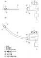
参考提案例を図1〜図5と共に説明する。図1において、この遠隔操作型アクチュエータは、回転式の工具1を保持する先端部材2と、この先端部材2が先端に姿勢変更自在に取付けられた細長形状のスピンドルガイド部3と、このスピンドルガイド部3の基端が結合された駆動部ハウジング4aと、この駆動部ハウジング4a内の工具回転用駆動機構4bおよび姿勢変更用駆動機構4cを制御するコントローラ5とを備える。駆動部ハウジング4aは、内蔵の工具回転用駆動機構4bおよび姿勢変更用駆動機構4cと共に駆動部4を構成する。スピンドルガイド部3の基端は駆動部ハウジング4aに対し、結合手段であるボルト51により、着脱自在に結合されている。図1の(A)と(B)は、それぞれ形状が異なるスピンドルガイド部3を装着した状態を示す。Reference proposal examples will be described withreference to FIGS. In FIG. 1, the remote control type actuator includes a
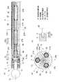
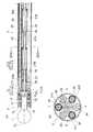
図2は、遠隔操作型アクチュエータの先端部材2およびスピンドルガイド部3の断面図である。先端部材2は、略円筒状のハウジング11の内部に、一対の軸受12によりスピンドル13が回転自在に支持されている。スピンドル13は、先端側が開口した筒状で、中空部に工具1のシャンク1aが嵌合状態に挿入され、回り止めピン14によりシャンク1aが回転不能に結合される。この先端部材2は、先端部材連結部15を介してスピンドルガイド部3の先端に取付けられる。先端部材連結部15は、先端部材2を姿勢変更自在に支持する手段であり、球面軸受からなる。具体的には、先端部材連結部15は、ハウジング11の基端の内径縮径部からなる被案内部11aと、スピンドルガイド部3の先端に固定された抜け止め部材21の鍔状部からなる案内部21aとで構成される。両者11a,21aの互いに接する各案内面F1,F2は、スピンドル13の中心線CL上に曲率中心Oが位置し、基端側ほど径が小さい球面とされている。これにより、スピンドルガイド部3に対して先端部材2が抜け止めされるとともに、姿勢変更自在に支持される。 FIG. 2 is a cross-sectional view of the
スピンドルガイド部3は、駆動部ハウジング4a内の工具回転用駆動源41(図3)の回転力を前記スピンドル13へ伝達する回転軸22を有する。この例では、回転軸22はワイヤとされ、ある程度の弾性変形が可能である。ワイヤの材質としては、例えば金属、樹脂、グラスファイバー等が用いられる。ワイヤは単線であっても、撚り線であってもよい。図2(C)に示すように、スピンドル13と回転軸22とは、自在継手等の継手23を介して回転伝達可能に接続されている。継手23は、スピンドル13の閉塞した基端に設けられた溝13aと、回転軸22の先端に設けられ前記溝13aに係合する突起22aとで構成される。上記溝13aと突起22aとの連結箇所の中心は、前記案内面F1,F2の曲率中心Oと同位置である。回転軸22と突起22aは別部材として構成してもよい。 The
スピンドルガイド部3は、このスピンドルガイド部3の外郭となる外郭パイプ25を有する。外郭パイプ25は両端に貫通した中空状で、その中空孔24は、中心部の円形孔部24aと、この円形孔部24aの外周における互いに120度の位相をなす周方向位置から外径側へ凹んだ3つの溝状部24bとでなる。溝状部24bの先端の周壁は、断面半円形である。例えば、外郭パイプ25の外径は8〜10mm、溝状部24以外の箇所の内径は3〜5mmである。また、外郭パイプ25の材質としては、ステンレス、チタン等が適する。
外郭パイプ25を上記断面形状としたことにより、外郭パイプ25の溝状部24b以外の箇所の肉厚tを厚くすることができる。それにより、外郭パイプ25の断面2次モーメントを、同外径の中実シャフトの1/2以上とすることができる。例えば、ステンレス材料からなる外径8mmの中実シャフトの場合、断面2次モーメントは約200mm4である。The
By making the
前記中空孔24の円形孔部24aには、前記回転軸22が配置される。回転軸22は、それぞれ軸方向に離れて配置された複数の転がり軸受26によって回転自在に支持されている。各転がり軸受26間には、これら転がり軸受26に予圧を発生させるためのばね要素27A,27Bが設けられている。ばね要素27A,27Bは、例えば圧縮コイルばねである。転がり軸受26の内輪に予圧を発生させる内輪用ばね要素27Aと、外輪に予圧を発生させる外輪用ばね要素27Bとがあり、これらが交互に配置されている。前記抜け止め部材21は、固定ピン28により外郭パイプ25のパイプエンド部25aに固定され、その先端内周部で転がり軸受29を介して回転軸22の先端部を回転自在に支持している。パイプエンド部25aは、外郭パイプ25と別部材とし、溶接等により結合してもよい。 The
前記中空孔24の各溝状部24bには、両端に貫通する中空のガイドパイプ30が設けられ、各ガイドパイプ30の内径孔であるガイド孔30a内に姿勢操作部材31(31U,31L,31R)が進退自在に挿通されている。この例では、姿勢操作部材31は、ワイヤ31aと、その両端の柱状ピン31bとでなる。先端部材2側の柱状ピン31bの先端は球面状で、ハウジング11の基端面11bに当接している。ハウジング11の基端面11bは、外径側ほどスピンドルガイド部3側に近い傾斜面とされている。駆動部ハウジング4a側の柱状ピン31bの先端も球面状で、後記レバー43b(図3)の側面に当接している。 Each groove-
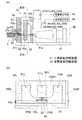
図3は、駆動部ハウジング4a内の工具回転用駆動機構4bおよび姿勢変更用駆動機構4cを示す。工具回転用駆動機構4bは、工具回転用駆動源41を備える。工具回転用駆動源41は、例えば電動モータであり、その出力軸41aが前記回転軸22の基端に結合させてある。なお、回転軸22は、後記レバー43bUに形成された開口44を貫通させてある。 FIG. 3 shows a tool
姿勢変更用駆動機構4cは、各姿勢操作部材31(31U,31L,31R)にそれぞれ対応する3個の姿勢変更用駆動源42(42U,42L,42R)を備える。姿勢変更用駆動源42は、例えば電動リニアアクチュエータであり、図3(A)の左右方向に移動する出力ロッド42aの動きが、増力伝達機構43を介して前記姿勢操作部材31に伝達される。増力伝達機構43は、支軸43a回りに回動自在なレバー43b(43bU,43bL,43bR)を有し、このレバー43bにおける支軸43aからの距離が長い作用点P1に出力ロッド42aの力が作用し、支軸43aからの距離が短い力点P2で姿勢操作部材31に力を与える構成であり、姿勢変更用駆動源42の出力が増力して姿勢操作部材31に伝達される。増力伝達機構43を設けると、小さな出力のリニアアクチュエータでも姿勢操作部材31に大きな力を与えることができるので、リニアアクチュエータの小型化が可能になる。姿勢変更用駆動源42は、回転モータであってもよい。また、リニアアクチュエータ等を設ける代わりに、手動により先端部材2の姿勢を遠隔操作してもよい。 The posture
姿勢変更用駆動機構4cには、各姿勢変更用駆動源42(42U,42L,42R)の動作量をそれぞれ個別に検出する動作量検出器45(45U,45L,45R)が設けられている。これら動作量検出器45の検出値は、姿勢検出手段46に出力される。姿勢検出手段46は、動作量検出器45の出力により、先端部材2のX軸およびY軸(図2)回りの傾動姿勢を検出する。姿勢検出手段46は、上記傾動姿勢と動作量検出器45の出力信号との関係を演算式またはテーブル等により設定した関係設定手段(図示せず)を有し、入力された出力信号から前記関係設定手段を用いて傾動姿勢を検出する。この姿勢検出手段46は、コントローラ5に設けられたものであっても、あるいは外部の制御装置に設けられたものであってもよい。 The posture
また、姿勢変更用駆動機構4cには、電動アクチュエータである各姿勢変更用駆動源42(42U,42L,42R)に供給される電力量をそれぞれ個別に検出する供給電力計47(47U,47L,47R)が設けられている。これら供給電力計47の検出値は、荷重検出手段48に出力される。荷重検出手段48は、供給電力計47の出力により、先端部材2に作用する荷重を検出する。荷重検出手段48は、上記荷重と供給電力計47の出力信号との関係を演算式またはテーブル等により設定した関係設定手段(図示せず)を有し、入力された出力信号から前記関係設定手段を用いて荷重を検出する。この荷重検出手段48は、コントローラ5に設けられたものであっても、あるいは外部の制御装置に設けられたものであってもよい。 In addition, the posture changing
コントローラ5は、前記姿勢検出手段46および荷重検出手段48の検出値に基づき、工具回転用駆動源41および姿勢変更用駆動源42を制御する。 The
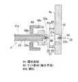
図4は、スピンドルガイド部3と駆動部ハウジング4aの結合部の構造を示す。なお、同図は、スピンドルガイド部3と駆動部ハウジング4aが分離された状態を表している。スピンドルガイド部3の基端にフランジ部50が一体に設けられ、このフランジ部50を結合手段である複数本のボルト51により駆動部ハウジング4aに結合させてある。詳しくは、フランジ部50は、基端面の中央部に凸部50aを有し、この凸部50aを駆動部ハウジング4aの凹部52に嵌合させて結合される。凹部52の底部から反対側に貫通して、回転軸22が挿通される中心貫通孔53と、各姿勢操作部材31がそれぞれ挿通される偏心貫通孔54とが設けられている。複数本のボルト51は円周方向に分散して配置されており、その頭部51aをフランジ部50の駆動部ハウジング4aと反対側の側面に当接させ、軸部51bをフランジ部50のボルト挿通孔55に挿通させて、駆動部ハウジング4aのボルト孔56に螺合させてある。この図の例では、フランジ部50は、スピンドルガイド部3の外郭パイプ25と別部材であるが、外郭パイプ25に一体に形成されたものであってもよい。 FIG. 4 shows the structure of the connecting portion between the
また、スピンドルガイド部3と駆動部ハウジング4aの結合部には、両者の回転軸22の軸心回りの位相を合わせる位相合わせ手段57が設けられている。この位相合わせ手段57は、フランジ部50の駆動部ハウジング4aに対向する面の少なくとも1箇所に位相合わせピン58を突出させて設け、この位相合わせピン58の先端を、駆動部ハウジング4aの位相合わせ孔59に挿入させるものである。 Further, a phase matching means 57 is provided at the coupling portion between the
回転軸22は、スピンドルガイド部3内のガイド部内部分22aと、駆動部ハウジング4a内のハウジング内部分22bとでなり、これらガイド部内部分22aとハウジング内部分22bとが、カップリング60により、軸心方向に分離可能かつ軸心回りに回転伝達可能に連結される。図5に示すように、カップリング60は、回転軸22のガイド部内部分22aの軸端に固定状態で嵌合したガイド部側カップリング体60aと、回転軸22のハウジング内部分22bの軸端に固定状態で嵌合したハウジング側カップリング体60bとでなる。ガイド部内部分22aとガイド部側カップリング体60aの固定、およびハウジング内部分22bとハウジング側カップリング体60bの固定は、例えば圧入により行われる。ガイド部側カップリング体60aの対向側端には係合溝61が形成され、ハウジング側カップリング体60bの対向側端には係合凸部62が形成され、スピンドルガイド部3と駆動部ハウジング4aとが結合した状態において、係合溝61に係合凸部62が係合することにより、ハウジング側カップリング体60bからガイド部側カップリング体60aへ回転伝達が可能になる。 The
この遠隔操作型アクチュエータの動作を説明する。
工具回転用駆動源41を駆動すると、その回転力が回転軸22を介してスピンドル13に伝達されて、スピンドル13と共に工具1が回転する。工具1を回転させて骨等を切削加工する際に先端部材2に作用する荷重は、供給電力計47の検出値から、荷重検出手段48によって検出される。このように検出される荷重の値に応じて遠隔操作型アクチュエータ全体の送り量や後記先端部材2の姿勢変更を制御することにより、先端部材2に作用する荷重を適正に保った状態で骨の切削加工を行える。The operation of this remote control type actuator will be described.
When the tool rotation drive
使用時には、3つの姿勢変更用駆動源42(42U,42L,42R)を駆動し、各姿勢操作部材31(31U,31L,31R)を互いに連係させて進退させることで、先端部材2の姿勢変更を遠隔操作で行う。
例えば、図2における上側の1つの姿勢操作部材31Uを先端側へ進出させ、かつ他の2つの姿勢操作部材31L,31Rを後退させると、上側の姿勢操作部材31Uによって先端部材2のハウジング11が押されることにより、先端部材2は図2(A)において先端側が下向きとなる側へ案内面F1,F2に沿って姿勢変更する。このとき、各姿勢操作部材31の進退量が適正になるよう、各姿勢変更用駆動源42が制御される。各姿勢操作部材31を逆に進退させると、左右の姿勢操作部材31L,31Rによって先端部材2のハウジング11が押されることにより、先端部材2は図2(A)において先端側が上向きとなる側へ案内面F1,F2に沿って姿勢変更する。
また、上側の姿勢操作部材31Uは静止させた状態で、左側の姿勢操作部材31Lを先端側へ進出させ、かつ右側の姿勢操作部材31Rを後退させると、左側の姿勢操作部材31Lによって先端部材2のハウジング11が押されることにより、先端部材2は右向き、すなわち図2(A)において紙面の裏側向きとなる側へ案内面F1,F2に沿って姿勢変更する。左右の姿勢操作部材31L,31Rを逆に進退させると、右の姿勢操作部材31Rによって先端部材2のハウジング11が押されることにより、先端部材2は左向きとなる側へ案内面F1,F2に沿って姿勢変更する。
このように姿勢操作部材31を円周方向の3箇所に設けることにより、先端部材2を上下左右の2軸(X軸、Y軸)の方向に姿勢変更することができる。その際、先端部材連結部15には、3つの姿勢操作部材31の圧力、および抜け止め部材21からの反力が作用しており、これらの作用力の釣り合いにより先端部材2の姿勢が決定される。この構成では、3つの姿勢操作部材31で先端部材2のハウジング11に加圧されるため、先端部材2の姿勢安定性が高い。At the time of use, the posture change of the
For example, when the upper one
Further, when the left
Thus, by providing the
先端部材2のハウジング11の基端面11bが外径側ほどスピンドルガイド部3側に近い傾斜面とされているため、姿勢操作部材31がハウジング11の基端面11bを押したときに、姿勢操作部材31に対してハウジング11の基端面11bが滑りやすく、ハウジング11の円滑な姿勢変更ができる。 Since the proximal end surface 11b of the
姿勢操作部材31はガイドパイプ30のガイド孔30aに挿通されているため、姿勢操作部材31が長手方向と交差する方向に位置ずれすることがなく、常に先端部材2に対し適正に作用することができ、先端部材2の姿勢変更動作が正確に行われる。また、姿勢操作部材31はワイヤからなり可撓性であるため、スピンドルガイド部3が湾曲した状態でも先端部材2の姿勢変更動作が確実に行われる。さらに、スピンドル13と回転軸22との連結箇所の中心が案内面F1,F2の曲率中心Oと同位置であるため、先端部材2の姿勢変更によって回転軸22に対して押し引きする力がかからず、先端部材2が円滑に姿勢変更できる。 Since the
この遠隔操作型アクチュエータは、例えば人工関節置換手術において骨の髄腔部を削るのに使用されるものであり、施術時には、先端部材2の全部または一部が患者の体内に挿入して使用される。このため、上記のように先端部材2の姿勢を遠隔操作で変更できれば、常に工具1を適正な姿勢に保持した状態で骨の加工をすることができ、人工関節挿入用穴を精度良く仕上げることができる。 This remote control type actuator is used, for example, for cutting the medullary cavity of bone in artificial joint replacement surgery. During the operation, all or part of the
細長形状であるスピンドルガイド部3は、外郭パイプ25の中心部に回転軸22を設け、この回転軸22との周囲に、姿勢操作部材31を収容したガイドパイプ30を互いに120度の位相をなす周方向位置に配置したことにより、回転軸22およびガイドパイプ30をバランス良く設けることができる。外郭パイプ25の溝状部24b以外の箇所の肉厚が厚いため、スピンドルガイド部3の剛性(断面2次モーメント)が高い。そのため、先端部材2の位置決め精度が向上させられるとともに、切削性を向上させられる。また、溝状部24bにガイドパイプ30を配置したことにより、ガイドパイプ30の円周方向の位置決めを容易に行え、組立性が良好である。 The elongated
回転軸22を支持する転がり軸受26の外径面を、ガイドパイプ30で支持させたため、余分な部材を用いずに転がり軸受26の外径面を支持できる。また、ばね要素27A,27Bにより転がり軸受26に予圧がかけられているため、ワイヤからなる回転軸22を高速回転させることができる。そのため、スピンドル13を高速回転させて加工することができ、加工の仕上がりが良く、工具1に作用する切削抵抗を低減させられる。ばね要素27A,27Bは隣合う転がり軸受26間に設けられているので、スピンドルガイド部3の径を大きくせずにばね要素27A,27Bを設けることができる。 Since the outer diameter surface of the rolling
結合手段であるボルト51で駆動部ハウジング4aに対しスピンドルガイド部3を着脱自在に結合したため、図1(A),(B)のように、1つの駆動部ハウジング4aに対して、被切削物の形状に合わせた様々な形状のスピンドルガイド部3を選択的に取付けることができる。また、駆動部ハウジング4aからスピンドルガイド部3を容易に外すことができるため、例えば人工関節置換手術のような手術器具をして使用する場合、患者の体内に接触するスピンドルガイド部3のみを滅菌処理することが可能である。患者の体内に接触しない駆動部ハウジング4aについては、手術時にカバー等を覆うことで対応できる。これらのことから、遠隔操作型アクチュエータの装置全体の部品点数の削減とコスト低減ができる。 Since the
特に、この実施形態では、スピンドルガイド部3の基端にフランジ部50を設けたことにより、スピンドルガイド部3と駆動部ハウジング4aの着脱が容易になり、着脱操作性の向上が図られている。また、結合手段をボルト51としたことで、着脱操作性が良好であり、しかも簡単で安価な構造が実現されている。 In particular, in this embodiment, since the
スピンドルガイド部3としては、直線状のものの他、曲がり具合が異なる複数のものを用意しておくのが望ましい。スピンドルガイド部3は、全体がほぼ同一曲率の湾曲状であっても、部分的に曲率が異なる形状であってもよい。また、一部分のみが湾曲形状であってもよい。スピンドルガイド部3を湾曲形状とする場合、外郭パイプ25、ガイドパイプ30、および補強シャフト34(例えば、図9)を湾曲形状とする必要がある。また、回転軸22は変形しやすい材質を用いるのが良く、例えば形状記憶合金が適する。 As the
図6は、スピンドルガイド部3と駆動部ハウジング4aの結合部の異なる構造を示す。同図は、スピンドルガイド部3と駆動部ハウジング4aが分離された状態を表している。この結合部の構造も、前記同様、スピンドルガイド部3の基端にフランジ部50が一体に設けられ、このフランジ50の凸部50aを駆動部ハウジング4aの凹部52に嵌合させる。駆動部ハウジング4aのスピンドルガイド部3との対向面に環状突部65が設けられており、この環状突部65の内周にフランジ部50を嵌合させ、環状突部65の外周面に形成されたねじ部65aに結合手段であるナット部材66の内周ねじ部66aを螺合させることにより、フランジ部50を駆動部ハウジング4aに結合する。ナット部材66は袋状で、底部に開口66bを有し、この開口66bにスピンドルガイド部3が挿通され、開口66bの周囲の袋側の底面がフランジ部50の駆動部ハウジング4aと反対側の側面に当接することで、フランジ部50を駆動部ハウジング4aとナット部材66とで両側から挟み付けて固定する。この結合部の構造も、駆動部ハウジング4aに対するスピンドルガイド部3の着脱操作性が良好であり、しかも簡単で安価な構造が実現されている。 FIG. 6 shows a different structure of the connecting portion between the
この遠隔操作型アクチュエータは、スピンドルガイド部3が中空状であることを利用して、工具1等を冷却する冷却手段70を図7のように設けることができる。すなわち、冷却手段70は、遠隔操作型アクチュエータの外部に設けた冷却液供給装置71と、この冷却液供給装置71から供給される冷却液をスピンドルガイド部3、および先端部材2の内部を通して先端側に導く冷却液供給管72とでなり、先端部材2の先端から工具1に向けて軸方向に冷却液を吐出させる。冷却液供給管72は、冷却液供給装置71からスピンドルガイド部3までの外部分72aと、スピンドルガイド部3および先端部材2の内部を通る内部分72bとでなり、内部分72bでは、スピンドルガイド部3の外郭パイプ25(図2)および先端部材2のハウジング11(図2)が冷却液供給管72になっている。 This remote control type actuator can be provided with a cooling means 70 for cooling the
冷却液がスピンドルガイド部3および先端部材2の内部を通過する際に、回転軸22、転がり軸受26,29、およびスピンドル13を冷却する。これらの回転する部分は、回転摩擦により発熱する。また、先端部材2から吐出される冷却液により、工具1および被加工物が冷却される。このように、スピンドルガイド部3および先端部材2の内部に冷却液を通したことにより、冷却液供給用の管を外部に設けなくて済み、スピンドルガイド部3および先端部材2を簡素化ならびに小径化できる。外郭パイプ25内に通過させる冷却液の流量が少ない場合は、さらに外部から冷却液を供給し、工具1や被加工物を冷却してもよい。なお、前記冷却液を転がり軸受26,29の潤滑に兼用させてもよい。そうすれば、軸受に一般的に使用されているグリス等を使用しなくてもよく、しかも別に潤滑装置を設けなくて済む。 When the coolant passes through the inside of the
上記冷却液は、水もしくは生理食塩水であるのが望ましい。冷却液が水もしくは生理食塩水であれば、先端部材2を生体内に挿入して加工を行う場合に冷却液が生体に悪影響を与えないからである。冷却液を水もしくは生理食塩水とする場合、冷却液と接する部品の材質は、耐腐食性に優れたステンレスであるのが望ましい。この遠隔操作型アクチュエータを構成する他の部品も、ステンレス製であってもよい。 The cooling liquid is preferably water or physiological saline. This is because if the coolant is water or physiological saline, the coolant does not adversely affect the living body when the
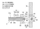
上記冷却手段70を設ける場合、スピンドルガイド部3と駆動部ハウジング4aの結合部をこの発明の実施形態に係る図8の構造とすることができる。すなわち、図4の結合部の構造において、フランジ部50の薄肉部50bに、スピンドルガイド部3内と外部とを連通する冷却液注入孔73を設け、この冷却液注入孔73の外部側端に管継手74を介して冷却液供給管72の外部分72aを結合してある。
駆動部ハウジング4aの凹部52にフランジ部50の凸部50aを嵌合させた状態において、凹部52には凸部50aに占められていない空間75、換言すればスピンドルガイド部3と駆動部ハウジング4aの間の空間75が形成されている。この空間75に高圧空気を注入するための高圧空気注入孔76が設けられている。回転軸22のガイド部内部分22aが挿通されるフランジ部50の孔、および回転軸22のハウジング内部分22bが挿通される中心貫通孔53は、シール部材77により密封する。シール部材77は、例えば回転軸22のガイド部内部分22aおよびハウジング内部分22bをそれぞれ支持する滑り軸受とする。また、フランジ部50の凸部50aの根元部分と駆動部ハウジング4aの凹部52の出口部分との間には、Oリング78を介在させる。そして、ポンプ等により外部から高圧空気注入孔76を介して空間75に高圧空気を注入することで、空間75をスピンドルガイド部3および駆動部ハウジング4a内の空間よりも高圧である高圧領域に生成する。In the case where the cooling means 70 is provided, the connecting portion between the
In a state where the
このように、スピンドルガイド部3と駆動部ハウジング4aの間に高圧領域を生成することにより、スピンドルガイド部3で使用する冷却液が駆動部ハウジング4a内に侵入することを防止できる。スピンドルガイド部3の基端を駆動部ハウジング4aに結合したときに生じる空間75を高圧領域にすれば、別に高圧領域用の空間を設けなくて済み、構造を簡素にできる。 Thus, by generating a high pressure region between the
図9は異なる実施形態を示す。この遠隔操作型アクチュエータは、スピンドルガイド部3の外郭パイプ25を、前記実施形態の図2に示す形状のパイプに代えて、肉厚が均一のパイプにしてある。外郭パイプ25内には、互いに120度の位相をなす周方向位置に3本のガイドパイプ30が設けられ、各ガイドパイプ30の内径孔であるガイド孔30a内に姿勢操作部材31が進退自在に挿通してある。また、ガイドパイプ30と同一ピッチ円C上に、ガイドパイプ30と交互に補強シャフト34が配置されている。補強シャフト34は中実のシャフトで、スピンドルガイド部3の剛性を確保するためのものである。補強シャフト34は、ガイドパイプ30と共に、外郭パイプ25の内径面におよび転がり軸受26の外径面に接し、転がり軸受26の外径面を支持している。他は、前記実施形態と同じ構成である。 FIG. 9 shows a different embodiment. In this remote control type actuator, the
図10はさらに異なる実施形態を示す。この遠隔操作型アクチュエータは、スピンドルガイド部3の外郭パイプ25の内径面と回転軸22の間にガイドパイプ30が1本だけ設けられ、このガイドパイプ30の内径孔であるガイド孔30a内に姿勢操作部材31が進退自在に挿通してある。また、ガイドパイプ30と同一ピッチ円C上に、前記同様の補強シャフト34が複数本配置されている。姿勢操作部材31が位置する周方向位置に対し180度の位相の位置には、先端部材2のハウジング11の基端面とスピンドルガイド部3の外郭パイプ25の先端面との間に、例えば圧縮コイルばねからなる復元用弾性部材32が設けられている。この復元用弾性部材32は、先端部材2を所定姿勢側へ付勢する作用をする。案内面F1,F2は、曲率中心が点Oである球面、または点Oを通るX軸を軸心とする円筒面である。他は、前記実施形態と同じ構成である。 FIG. 10 shows a further different embodiment. In this remote control type actuator, only one
図11は、この遠隔操作型アクチュエータの工具回転用駆動機構4bおよび姿勢変更用駆動機構4cを示す。姿勢変更用駆動機構4cは、姿勢変更用駆動源42が1個だけ設けられ、増力伝達機構43が1本の姿勢操作部材31に対応した形態とされている。工具回転用駆動機構4bは、図3のものと同じ構成である。 FIG. 11 shows a tool
先端部材2の姿勢変更は、以下のように行う。例えば、姿勢変更用駆動源42により姿勢操作部材31を先端側へ進出させると、姿勢操作部材31によって先端部材2のハウジング11が押されて、先端部材2は図10(A)において先端側が下向きとなる側へ案内面F1,F2に沿って姿勢変更する。逆に、姿勢変更用駆動源42により姿勢操作部材31を後退させると、復元用弾性部材32の弾性反発力によって先端部材2のハウジング11が押し戻され、先端部材2は図10(A)において先端側が上向きとなる側へ案内面F1,F2に沿って姿勢変更する。その際、先端部材連結部15には、姿勢操作部材31の圧力、復元用弾性部材32の弾性反発力、および抜け止め部材21からの反力が作用しており、これらの作用力の釣り合いにより先端部材2の姿勢が決定される。先端部材2の姿勢は、動作量検出器45の検出値から、姿勢検出手段46によって検出される。そのため、遠隔操作で先端部材2の姿勢を適正に制御できる。 The posture of the
図12はさらに異なる実施形態を示す。この遠隔操作型アクチュエータは、外郭パイプ25内の互いに180度の位相にある周方向位置に2本のガイドパイプ30を設け、そのガイドパイプ30の内径孔であるガイド孔30a内に姿勢操作部材31が進退自在に挿通してある。2本のガイドパイプ30間には、ガイドパイプ30と同一ピッチ円C上に複数本の補強シャフト34が配置されている。復元用弾性部材32は設けられていない。案内面F1,F2は、曲率中心が点Oである球面、または点Oを通るX軸を軸心とする円筒面である。 FIG. 12 shows a further different embodiment. In this remote operation type actuator, two
駆動部4(図示せず)には、2つの姿勢操作部材31をそれぞれ個別に進退操作させる2つの姿勢変更用駆動源42(図示せず)が設けられており、これら2つの姿勢変更用駆動源42を互いに逆向きに駆動することで先端部材2の姿勢変更を行う。例えば、図12における上側の姿勢操作部材31を先端側へ進出させ、かつ下側の姿勢操作部材31を後退させると、上側の姿勢操作部材31によって先端部材2のハウジング11が押されることにより、先端部材2は図12(A)において先端側が下向きとなる側へ案内面F1,F2に沿って姿勢変更する。逆に、両姿勢操作部材31を逆に進退させると、下側の姿勢操作部材31によって先端部材2のハウジング11が押されることにより、先端部材2は図12(A)において先端側が上向きとなる側へ案内面F1,F2に沿って姿勢変更する。その際、先端部材連結部15には、上下2つの姿勢操作部材31の圧力、および抜け止め部材21からの反力が作用しており、これらの作用力の釣り合いにより先端部材2の姿勢が決定される。この構成では、2つの姿勢操作部材31で先端部材2のハウジング11に加圧されるため、1つの姿勢操作部材31だけで加圧される前記実施形態に比べ、先端部材2の姿勢安定性を高めることができる。 The drive unit 4 (not shown) is provided with two posture change drive sources 42 (not shown) for individually moving the two
図13に示す遠隔操作型アクチュエータは、先端部材2のハウジング11の基端面11b(同図(C))に径方向の溝部11cを形成し、この溝部11cの底面に、姿勢操作部材31の球面状をした先端を当接させている。溝部11cおよび姿勢操作部材31は回転防止機構37を構成し、溝部11cに挿入された姿勢操作部材31の先端部が溝部11cの側面に当たることで、先端部材2がスピンドルガイド部3に対してスピンドル13の中心線CL回りに回転するのを防止している。 In the remote operation type actuator shown in FIG. 13, a
このような回転防止機構37を設けることにより、姿勢操作部材31の進退を制御する姿勢操作用駆動機構4c(図11)やその制御装置の故障等により工具1を保持する先端部材2が制御不能となった場合でも、先端部材2が中心線CL回りに回転して加工箇所の周りを傷付けたり、先端部材2自体が破損したりすることを防止できる。なお、図13は姿勢操作部材31が1本である場合の例を示しているが、姿勢操作部材31が複数本である場合にも同様のことが言える。 By providing such an
上記各実施形態は、先端部材2のハウジング11の基端面11bにおける姿勢操作部材31が接する箇所が、外径側ほどスピンドルガイド部3側に近い傾斜面とされ、その傾斜面は断面直線状とされているが、図14に示すように、断面曲線状、例えば円弧状としてもよい。場合によっては、先端部材2のハウジング11の基端面11bを傾斜面とせずに、姿勢操作部材31の進退方向と垂直な面としてもよい。なお、図14は姿勢操作部材31が1本である場合の例を示しているが、姿勢操作部材31が複数本である場合にも同様のことが言える。 In each of the above embodiments, the position where the
また、上記各実施形態は、姿勢操作部材31がワイヤ31aとその両端の柱状ピン31bとでなるが、柱状ピン31bを省いてワイヤ31aだけで姿勢操作部材31を構成してもよい。また、ワイヤ31aに代えて、比較的長手方向に短い柱状体や球体(図示せず)を複数並べて、姿勢操作部材31を構成してもよい。 In each of the above-described embodiments, the
以上、医療用の遠隔操作型アクチュエータについて説明したが、この発明はそれ以外の用途の遠隔操作型アクチュエータにも適用できる。例えば、機械加工用とした場合、湾曲状をした孔のドリル加工や、溝内部の奥まった箇所の切削加工が可能になる。 The medical remote control actuator has been described above, but the present invention can be applied to remote control actuators for other purposes. For example, in the case of machining, drilling of a curved hole or cutting of a deep part inside the groove is possible.
1…工具
2…先端部材
3…スピンドルガイド部
4a…駆動部ハウジング
5…コントローラ
13…スピンドル
15…先端部材連結部
22…回転軸
22a…ガイド部内部分
22b…ハウジング内部分
26,29…転がり軸受
30…ガイドパイプ
30a…ガイド孔
31…姿勢操作部材
41…工具回転用駆動源
42…姿勢変更用駆動源
50…フランジ部
51…ボルト(結合手段)
57…位相合わせ手段
60…カップリング
65…環状突部
66…ナット部材
66b…開口
70…冷却手段
75…空間DESCRIPTION OF
57 ... Phase matching means 60 ... Coupling 65 ...
Claims (10)
Translated fromJapanese前記先端部材は、工具を保持するスピンドルを回転自在に支持し、前記スピンドルガイド部は、前記駆動部ハウジング内に設けられた工具回転用駆動源の回転を前記スピンドルに伝達する回転軸と、両端に貫通したガイド孔とを内部に有し、先端が前記先端部材に接して進退動作することにより前記先端部材を姿勢変更させる姿勢操作部材を前記ガイド孔内に進退自在に挿通し、前記姿勢操作部材を進退させる姿勢変更用駆動源を前記駆動部ハウジング内に設け、
結合手段により前記駆動部ハウジングに対し前記スピンドルガイド部を着脱自在に結合し、前記スピンドルガイド部と前記駆動部ハウジングの間に空間を設け、その空間に高圧空気を注入することにより前記スピンドルガイド部および前記駆動部ハウジング内の空間よりも高圧である高圧領域を生成したことを特徴とする遠隔操作型アクチュエータ。An elongated spindle guide part, a tip member attached to the tip of the spindle guide part via a tip member connecting part so that the posture can be freely changed, and a drive part housing to which the base end of the spindle guide part is coupled. ,
The tip member rotatably supports a spindle that holds a tool, and the spindle guide portion includes a rotating shaft that transmits rotation of a driving source for tool rotation provided in the driving portion housing to the spindle, and both ends. A guide hole penetrating into the guide hole, and a posture operation member for changing the posture of the tip member by advancing and retreating with the tip contacting the tip member is inserted into the guide hole so as to be able to advance and retract. A posture changing drive source for moving the member forward and backward is provided in the drive unit housing,
The spindle guide unit is detachably coupledto the drive unit housing by coupling means, a space is provided between the spindle guide unit and the drive unit housing, and high pressure air is injected into the space, thereby the spindle guide unit. And a high-pressure region that is higher in pressure than the space in the drive unit housing .
Priority Applications (5)
| Application Number | Priority Date | Filing Date | Title |
|---|---|---|---|
| JP2009098715AJP5464892B2 (en) | 2009-04-15 | 2009-04-15 | Remote control type actuator |
| EP10764382.7AEP2420194B1 (en) | 2009-04-15 | 2010-04-07 | Remotely operated actuator |
| PCT/JP2010/056304WO2010119798A1 (en) | 2009-04-15 | 2010-04-07 | Remotely operated actuator |
| US13/200,942US8573090B2 (en) | 2009-04-15 | 2011-10-05 | Remote-controlled actuator |
| US14/045,387US8794100B2 (en) | 2009-04-15 | 2013-10-03 | Remote-controlled actuator |
Applications Claiming Priority (1)
| Application Number | Priority Date | Filing Date | Title |
|---|---|---|---|
| JP2009098715AJP5464892B2 (en) | 2009-04-15 | 2009-04-15 | Remote control type actuator |
Publications (2)
| Publication Number | Publication Date |
|---|---|
| JP2010246701A JP2010246701A (en) | 2010-11-04 |
| JP5464892B2true JP5464892B2 (en) | 2014-04-09 |
Family
ID=42982460
Family Applications (1)
| Application Number | Title | Priority Date | Filing Date |
|---|---|---|---|
| JP2009098715AExpired - Fee RelatedJP5464892B2 (en) | 2009-04-15 | 2009-04-15 | Remote control type actuator |
Country Status (4)
| Country | Link |
|---|---|
| US (2) | US8573090B2 (en) |
| EP (1) | EP2420194B1 (en) |
| JP (1) | JP5464892B2 (en) |
| WO (1) | WO2010119798A1 (en) |
Families Citing this family (11)
| Publication number | Priority date | Publication date | Assignee | Title |
|---|---|---|---|---|
| WO2010101086A1 (en)* | 2009-03-06 | 2010-09-10 | Ntn株式会社 | Navigation system for remotely operated actuator |
| JP5538795B2 (en)* | 2009-09-28 | 2014-07-02 | Ntn株式会社 | Remote control type actuator |
| JP5528207B2 (en)* | 2010-05-19 | 2014-06-25 | Ntn株式会社 | Link actuator |
| CA2902238A1 (en) | 2013-03-15 | 2014-09-18 | Stryker Corporation | End effector of a surgical robotic manipulator |
| US9314254B2 (en)* | 2013-03-15 | 2016-04-19 | DePuy Synthes Products, Inc. | Methods and devices for removing a spinal disc |
| US20140352483A1 (en)* | 2013-06-04 | 2014-12-04 | General Electric Company | Remote alignment tool |
| CN106108973A (en)* | 2016-08-08 | 2016-11-16 | 苏州益诺斯医疗科技有限公司 | A kind of medical dynamical system main frame |
| TWI642401B (en)* | 2017-03-03 | 2018-12-01 | 財團法人工業技術研究院 | Minimally invasive surgical device |
| WO2019100588A1 (en)* | 2017-11-21 | 2019-05-31 | 青岛理工大学 | Neurosurgical ultrasound focus assist three-stage atomization cooling and postoperative wound film forming device |
| KR101901424B1 (en) | 2018-06-20 | 2018-09-21 | 조현진 | medical chisel |
| US11471947B2 (en)* | 2019-06-06 | 2022-10-18 | Raytheon Technologies Corporation | Apparatus and methods for improvement of surface geometries of internal channels of additively manufactured components |
Family Cites Families (29)
| Publication number | Priority date | Publication date | Assignee | Title |
|---|---|---|---|---|
| US550783A (en)* | 1895-12-03 | Drill for boring curved holes | ||
| US3617143A (en)* | 1969-04-29 | 1971-11-02 | Custom Alloy Corp | Arcuate hole-cutting tool |
| DE2914455A1 (en) | 1979-04-10 | 1980-10-23 | Maschf Augsburg Nuernberg Ag | DEVICE FOR PRODUCING A COLLECTION IN A BONE |
| US4265231A (en) | 1979-04-30 | 1981-05-05 | Scheller Jr Arnold D | Curved drill attachment for bone drilling uses |
| US5356064A (en)* | 1991-10-18 | 1994-10-18 | United States Surgical Corporation | Apparatus and method for applying surgical staples to attach an object to body tissue |
| US5509918A (en)* | 1993-05-11 | 1996-04-23 | David Romano | Method and apparatus for drilling a curved bore in an object |
| AT400665B (en)* | 1993-06-28 | 1996-02-26 | Buermoos Dentalwerk | SURGICAL HANDPIECE |
| US5569254A (en)* | 1995-04-12 | 1996-10-29 | Midas Rex Pneumatic Tools, Inc. | Surgical resection tool having an irrigation, lighting, suction and vision attachment |
| US5814038A (en)* | 1995-06-07 | 1998-09-29 | Sri International | Surgical manipulator for a telerobotic system |
| US5649956A (en)* | 1995-06-07 | 1997-07-22 | Sri International | System and method for releasably holding a surgical instrument |
| JPH09135837A (en)* | 1995-11-13 | 1997-05-27 | Yasumasa Onuki | Ligating and suturing device |
| US6083228A (en)* | 1998-06-09 | 2000-07-04 | Michelson; Gary K. | Device and method for preparing a space between adjacent vertebrae to receive an insert |
| JP2001017446A (en)* | 1999-07-05 | 2001-01-23 | Nakanishi:Kk | Hand piece for medical purpose |
| US6920960B2 (en)* | 2001-06-28 | 2005-07-26 | Medtronic, Inc. | Lubrication cartridge for a pneumatically powered surgical instrument |
| JP4722340B2 (en)* | 2001-08-08 | 2011-07-13 | Thk株式会社 | Dynamic pressure sealing device and rotary joint device using the same |
| JP4384498B2 (en)* | 2002-02-08 | 2009-12-16 | チャナ,ガーシャラン,シン | Improved surgical device and method of use |
| WO2003101308A1 (en)* | 2002-06-04 | 2003-12-11 | Office Of Technology Licensing Stanford University | Device and method for rapid aspiration and collection of body tissue from within an enclosed body space |
| US7559927B2 (en)* | 2002-12-20 | 2009-07-14 | Medtronic Xomed, Inc. | Surgical instrument with telescoping attachment |
| US7549992B2 (en)* | 2002-12-20 | 2009-06-23 | Medtronic, Inc. | Surgical instrument with angled attachment |
| US7585300B2 (en)* | 2003-12-19 | 2009-09-08 | Spinascope, Inc. | Dissecting high speed burr for spinal surgery |
| US20060229624A1 (en)* | 2005-03-31 | 2006-10-12 | Zimmer Technology, Inc. | Orthopaedic cutting instrument and method |
| JP2007068636A (en)* | 2005-09-05 | 2007-03-22 | Olympus Corp | Cell collection apparatus |
| JP5096930B2 (en)* | 2006-01-13 | 2012-12-12 | ナブテスコ株式会社 | Driving apparatus for substrate transfer robot having cooling circulation passage |
| JP3868474B1 (en)* | 2006-05-08 | 2007-01-17 | 司工機株式会社 | Machining tools |
| JP4105200B2 (en) | 2006-05-11 | 2008-06-25 | 株式会社ナカニシ | Medical handpiece |
| US7648519B2 (en)* | 2006-09-13 | 2010-01-19 | Cambridge Endoscopic Devices, Inc. | Surgical instrument |
| US8161838B2 (en)* | 2008-12-22 | 2012-04-24 | Intuitive Surgical Operations, Inc. | Method and apparatus for reducing at least one friction force opposing an axial force exerted through an actuator element |
| EP2498668A4 (en)* | 2009-11-13 | 2013-08-07 | Hologic Inc | Access system with removable outflow channel |
| US8568417B2 (en)* | 2009-12-18 | 2013-10-29 | Charles River Engineering Solutions And Technologies, Llc | Articulating tool and methods of using |
- 2009
- 2009-04-15JPJP2009098715Apatent/JP5464892B2/ennot_activeExpired - Fee Related
- 2010
- 2010-04-07WOPCT/JP2010/056304patent/WO2010119798A1/enactiveApplication Filing
- 2010-04-07EPEP10764382.7Apatent/EP2420194B1/ennot_activeNot-in-force
- 2011
- 2011-10-05USUS13/200,942patent/US8573090B2/ennot_activeExpired - Fee Related
- 2013
- 2013-10-03USUS14/045,387patent/US8794100B2/ennot_activeExpired - Fee Related
Also Published As
| Publication number | Publication date |
|---|---|
| EP2420194A4 (en) | 2013-10-30 |
| US20140026704A1 (en) | 2014-01-30 |
| US20120031219A1 (en) | 2012-02-09 |
| JP2010246701A (en) | 2010-11-04 |
| WO2010119798A1 (en) | 2010-10-21 |
| EP2420194A1 (en) | 2012-02-22 |
| US8794100B2 (en) | 2014-08-05 |
| EP2420194B1 (en) | 2017-01-25 |
| US8573090B2 (en) | 2013-11-05 |
Similar Documents
| Publication | Publication Date | Title |
|---|---|---|
| JP5464892B2 (en) | Remote control type actuator | |
| EP2340772B1 (en) | Remote-controlled actuator | |
| WO2010041397A1 (en) | Remotely operated actuator | |
| WO2010061567A1 (en) | Remote control actuator | |
| JP5289470B2 (en) | Flexible cable | |
| WO2010137603A1 (en) | Remotely operated actuator | |
| JP5500890B2 (en) | Remote control type actuator | |
| JP5258495B2 (en) | Remote control type actuator | |
| WO2011037131A1 (en) | Remote operation actuator and plastic forming method for attitude operation member | |
| JP5557522B2 (en) | Remote control type actuator | |
| JP2010051439A (en) | Remote-controlled actuator | |
| JP5213735B2 (en) | Remote control type actuator | |
| JP5388702B2 (en) | Remote control type actuator | |
| JP5500891B2 (en) | Remote control type actuator | |
| JP5197293B2 (en) | Remote control type actuator | |
| JP5388701B2 (en) | Remote control type actuator | |
| JP2010046764A (en) | Remote operation type actuator | |
| JP2010088812A (en) | Remote control type actuator | |
| JP5213666B2 (en) | Remote control type actuator | |
| JP2010046197A (en) | Remote control type actuator | |
| JP5258594B2 (en) | Remote control type actuator | |
| JP5213654B2 (en) | Remote control type actuator |
Legal Events
| Date | Code | Title | Description |
|---|---|---|---|
| A621 | Written request for application examination | Free format text:JAPANESE INTERMEDIATE CODE: A621 Effective date:20120326 | |
| A131 | Notification of reasons for refusal | Free format text:JAPANESE INTERMEDIATE CODE: A131 Effective date:20130702 | |
| A521 | Request for written amendment filed | Free format text:JAPANESE INTERMEDIATE CODE: A523 Effective date:20130830 | |
| TRDD | Decision of grant or rejection written | ||
| A01 | Written decision to grant a patent or to grant a registration (utility model) | Free format text:JAPANESE INTERMEDIATE CODE: A01 Effective date:20140107 | |
| A61 | First payment of annual fees (during grant procedure) | Free format text:JAPANESE INTERMEDIATE CODE: A61 Effective date:20140121 | |
| R150 | Certificate of patent or registration of utility model | Free format text:JAPANESE INTERMEDIATE CODE: R150 Ref document number:5464892 Country of ref document:JP Free format text:JAPANESE INTERMEDIATE CODE: R150 | |
| R250 | Receipt of annual fees | Free format text:JAPANESE INTERMEDIATE CODE: R250 | |
| R250 | Receipt of annual fees | Free format text:JAPANESE INTERMEDIATE CODE: R250 | |
| R250 | Receipt of annual fees | Free format text:JAPANESE INTERMEDIATE CODE: R250 | |
| R250 | Receipt of annual fees | Free format text:JAPANESE INTERMEDIATE CODE: R250 | |
| R250 | Receipt of annual fees | Free format text:JAPANESE INTERMEDIATE CODE: R250 | |
| LAPS | Cancellation because of no payment of annual fees |