JP5462548B2 - Nucleic acid analyzer and nucleic acid analyzer using the same - Google Patents
Nucleic acid analyzer and nucleic acid analyzer using the sameDownload PDFInfo
- Publication number
- JP5462548B2 JP5462548B2JP2009187435AJP2009187435AJP5462548B2JP 5462548 B2JP5462548 B2JP 5462548B2JP 2009187435 AJP2009187435 AJP 2009187435AJP 2009187435 AJP2009187435 AJP 2009187435AJP 5462548 B2JP5462548 B2JP 5462548B2
- Authority
- JP
- Japan
- Prior art keywords
- nucleic acid
- light
- scatterer
- apex
- enzyme
- Prior art date
- Legal status (The legal status is an assumption and is not a legal conclusion. Google has not performed a legal analysis and makes no representation as to the accuracy of the status listed.)
- Expired - Fee Related
Links
Images


Landscapes
- Investigating, Analyzing Materials By Fluorescence Or Luminescence (AREA)
- Investigating Or Analysing Materials By The Use Of Chemical Reactions (AREA)
- Apparatus Associated With Microorganisms And Enzymes (AREA)
Description
Translated fromJapanese本発明は、核酸分析素子及びそれを用いた核酸分析装置に関する。 The present invention relates to a nucleic acid analysis element and a nucleic acid analysis apparatus using the same.
医療現場などにおいて、DNAやRNAなどの核酸の塩基配列を高速に調べる装置が要求されている。
従来、塩基配列を調べるために用いられている電気泳動を利用した方法では、検査対象のDNA又はRNA試料から逆転写反応を行い、終端が特定の塩基となった相補的DNA(cDNA)断片試料を調製する。この断片試料を、電気泳動により分子量ごとに分離することで、DNAやRNAの塩基配列を決定する。In the medical field etc., an apparatus for examining the base sequence of a nucleic acid such as DNA or RNA at high speed is required.
In the conventional method using electrophoresis, which is used for examining a base sequence, a reverse transcription reaction is performed from a DNA or RNA sample to be examined, and a complementary DNA (cDNA) fragment sample having a specific base at the end. To prepare. The fragment sample is separated for each molecular weight by electrophoresis to determine the base sequence of DNA or RNA.
核酸分析の所要時間を短くするために、核酸を基板上に2次元的に配列し、各核酸の塩基伸長反応を並列的に検出する方法が開発されている。この方法では、検出対象の核酸のテンプレート(1本鎖となった核酸)を、塩基伸長酵素と共に、基板上に2次元的に配列する。それを色素が結合したヌクレオチド(核酸の構成要素)が含まれた溶液中に浸す。検出対象の核酸にヌクレオチドが取り込まれる際、ヌクレオチドに結合していた色素が発する蛍光をCCDにより検出する。ヌクレオチドの種類ごとに異なる色素を結合させておけば、蛍光の波長を識別することにより、取り込まれるヌクレオチドの種類を同定し、核酸の塩基配列を同定することが出来る。この方法において、蛍光の検出感度を上げるためには、PCR(Polymerase chain reaction)法等のDNA断片増幅法を用いることにより、一つの核酸断片からそのコピーを合成し、同じ種類の核酸の塊(クラスタ)を形成する。このクラスタを観測することにより、蛍光強度を強くする。以上のように、検出対象の核酸を高密度に配列することにより、50万以上の並列処理が可能になり、スループット向上と試薬使用量低減が可能になる。 In order to shorten the time required for nucleic acid analysis, a method has been developed in which nucleic acids are two-dimensionally arranged on a substrate and base extension reactions of the nucleic acids are detected in parallel. In this method, a template of a nucleic acid to be detected (single-stranded nucleic acid) is two-dimensionally arranged on a substrate together with a base extension enzyme. It is immersed in a solution containing nucleotides (nucleic acid constituents) to which the dye is bound. When the nucleotide is incorporated into the nucleic acid to be detected, the fluorescence emitted from the dye that has been bound to the nucleotide is detected by the CCD. If different dyes are bound for each type of nucleotide, the type of nucleotide to be incorporated can be identified by identifying the wavelength of fluorescence, and the nucleotide sequence of the nucleic acid can be identified. In this method, in order to increase the fluorescence detection sensitivity, a DNA fragment amplification method such as a PCR (Polymerase chain reaction) method is used to synthesize a copy from one nucleic acid fragment, and the same type of nucleic acid mass ( Cluster). By observing this cluster, the fluorescence intensity is increased. As described above, by arranging the nucleic acids to be detected at high density, it becomes possible to perform parallel processing of 500,000 or more, thereby improving throughput and reducing reagent usage.
近年、核酸をコピーせずに、単分子の状態で、塩基伸長反応を観察する方法も開発されている(John Eid et al., Science Vol.323, p133 (2009))。この方法では、基板表面に微小開口を2次元的に形成し、各々の微小開口中に塩基伸長酵素を一つ固定する。検出対象の核酸は塩基伸長酵素に捕捉させる。色素が結合したヌクレオチドが含まれた溶液に浸けると、塩基伸長酵素により、ヌクレオチドが核酸に取り込まれる。このとき、微小開口を通過した励起光により、色素が励起され、蛍光が発生する。この蛍光を検出することにより、核酸に順次取り込まれるヌクレオチドの種類をリアルタイムに検出することが出来る。従来のクラスタを観測する方法では、クラスタを構成する各核酸の塩基伸長反応が、各々同じスピードで進むように、反応を人為的に制御する必要がある。例えば、取り込ませるヌクレオチドにターミネータ分子をつけておき、核酸に取り込まれた後、塩基伸長反応が一旦止まるようにする。その後紫外光照射によりターミネータの働きを止め、各分子一斉に次の反応が進むようにする。これに対し、単分子を測定する方法では、測定対象が1分子であるため、このような反応制御は不要で、高速な測定が可能になる。また、クラスタを用いた方法では、ばらつきの存在により、塩基伸長反応が進むにつれて、クラスタを構成する各分子の反応に不揃いが生じる。その結果、一つのサンプルで読み取ることが出来る塩基数(Read長)には限界がある。これに対し、単分子を測定する方法では、ばらつぎの影響がないため、Read長を大きくすることが出来る。 In recent years, a method of observing a base extension reaction in a single molecule state without copying nucleic acid has been developed (John Eid et al., Science Vol.323, p133 (2009)). In this method, a microscopic opening is formed two-dimensionally on the substrate surface, and one base elongation enzyme is immobilized in each microscopic opening. The nucleic acid to be detected is captured by a base extension enzyme. When immersed in a solution containing nucleotides to which a dye is bound, nucleotides are incorporated into nucleic acids by the base extension enzyme. At this time, the dye is excited by the excitation light that has passed through the minute aperture, and fluorescence is generated. By detecting this fluorescence, it is possible to detect in real time the type of nucleotide sequentially incorporated into the nucleic acid. In the conventional method of observing a cluster, it is necessary to artificially control the reaction so that the base extension reaction of each nucleic acid constituting the cluster proceeds at the same speed. For example, a terminator molecule is attached to the nucleotide to be incorporated so that the base extension reaction is temporarily stopped after incorporation into the nucleic acid. After that, the terminator is stopped by irradiation with ultraviolet light so that the next reaction proceeds at the same time. On the other hand, in the method of measuring a single molecule, since the measurement object is one molecule, such reaction control is unnecessary and high-speed measurement is possible. In addition, in the method using clusters, due to the presence of variations, the reactions of the molecules constituting the clusters become uneven as the base extension reaction proceeds. As a result, the number of bases (Read length) that can be read by one sample is limited. On the other hand, in the method of measuring a single molecule, since there is no effect of discontinuity, the Read length can be increased.
単分子核酸の塩基配列を読み取る装置において、ヌクレオチドが単分子核酸に取り込まれたとき発生する色素からの蛍光は微弱である。そのため、検出信号はノイズの影響を受けやすく、読み取り結果にエラーが生じる可能性がある。エラー率を小さくするためには、単分子核酸に結合した色素から発生する蛍光強度を増強することにより検出信号強度を大きくすることが好ましい。 In an apparatus for reading the base sequence of a unimolecular nucleic acid, the fluorescence from the dye generated when nucleotides are incorporated into the unimolecular nucleic acid is weak. Therefore, the detection signal is easily affected by noise, and an error may occur in the reading result. In order to reduce the error rate, it is preferable to increase the detection signal intensity by enhancing the fluorescence intensity generated from the dye bound to the monomolecular nucleic acid.
本発明は、読み取り結果のエラー率を小さくするために、単分子核酸に結合した色素から発生する蛍光強度を増強するものである。 The present invention enhances the fluorescence intensity generated from a dye bound to a single molecule nucleic acid in order to reduce the error rate of the reading result.
光透過性を有する基板上に、三角形の形状をした、導電性を有する散乱体を形成する。この散乱体に光を導入すると、散乱体中にはプラズモン共鳴が発生し、頂点部には強い近接場光が発生する。三角形の頂点部の材質と、それ以外の表面部の材質は異なるようにし、頂点部の材質は、塩基伸長反応を促進するための酵素(塩基伸長酵素)を固定させるのに必要な官能基が形成可能な材質とし、それ以外の表面部の材質は、塩基伸長酵素を固定させるのに必要な官能基が形成されない材料とする。散乱体が形成された基板を、塩基伸長酵素を固定させるのに必要な官能基を形成させるための溶液に浸すと、官能基が頂点部に選択的に形成される。さらに、塩基伸長酵素を含む溶液に浸すと、頂点部に塩基伸長酵素が固定される。頂点部の材質が異なった部分の幅は、いずれも塩基伸長酵素の幅の2倍よりも小さくなるようにする。このようにすれば、頂点部に塩基伸長酵素が2個以上つくことは出来ないため、頂点部に塩基伸長酵素1分子を選択的に固定させることが出来る。 A conductive scatterer having a triangular shape is formed over a light-transmitting substrate. When light is introduced into the scatterer, plasmon resonance occurs in the scatterer, and strong near-field light is generated at the apex. The material of the apex part of the triangle is different from the material of the other surface part, and the material of the apex part has a functional group necessary for immobilizing an enzyme (base extension enzyme) for promoting the base extension reaction. A material that can be formed is used, and the other surface material is a material that does not form a functional group necessary for immobilizing the base elongation enzyme. When the substrate on which the scatterer is formed is immersed in a solution for forming a functional group necessary for immobilizing the base extension enzyme, the functional group is selectively formed at the apex. Furthermore, when immersed in a solution containing a base elongation enzyme, the base elongation enzyme is fixed to the apex. The widths of the different parts of the apex material are all made smaller than twice the width of the base elongation enzyme. In this way, since two or more base elongation enzymes cannot be attached to the apex, one base elongase molecule can be selectively fixed to the apex.
頂点部に塩基伸長酵素が形成された散乱体を、検出対象の核酸(1本鎖となったDNAもしくはRNA)が含まれる溶液に浸すと、検出対象の核酸は、塩基伸長酵素に捕捉される。溶液中にヌクレオチドを導入すると、ヌクレオチドは、塩基伸長酵素により核酸に取り込まれる。このとき、あらかじめヌクレオチドに蛍光色素を結合させておくと、塩基伸長酵素近傍には近接場光が発生しているため、その近接場光により、取り込まれたヌクレオチドに結合した蛍光色素が励起され、蛍光が発生する。ヌクレオチドに結合した蛍光色素の発光波長は、ヌクレオチドの種類ごとに、異なるようにする。核酸分子に取り込まれた時に発生する蛍光波長を識別することにより、取り込まれたヌクレオチドの種類を同定することが出来る。 When a scatterer having a base extending enzyme formed at the apex is immersed in a solution containing nucleic acid to be detected (single-stranded DNA or RNA), the nucleic acid to be detected is captured by the base extending enzyme. . When nucleotides are introduced into the solution, the nucleotides are incorporated into the nucleic acid by a base extension enzyme. At this time, if the fluorescent dye is bound to the nucleotide in advance, near-field light is generated in the vicinity of the base extension enzyme, so that the fluorescent dye bound to the incorporated nucleotide is excited by the near-field light, Fluorescence is generated. The emission wavelength of the fluorescent dye bound to the nucleotide is different for each type of nucleotide. By identifying the fluorescence wavelength generated when incorporated into a nucleic acid molecule, the type of incorporated nucleotide can be identified.
上記方法において、三角形の頂点部には、プラズモン共鳴により、強い近接場光が発生し、その強度(パワー密度)は、入射光強度よりも強くなる。したがって、ヌクレオチドが核酸に取り込まれた際発生する蛍光強度は、導電性を有する散乱体を用いずに光照射した場合に比べ強くなる。その結果、信号強度を大きくすることが可能になり、読み取り結果におけるエラー率を小さくすることが出来る。 In the above method, strong near-field light is generated at the apex of the triangle due to plasmon resonance, and its intensity (power density) is higher than the incident light intensity. Therefore, the intensity of fluorescence generated when nucleotides are incorporated into nucleic acids is stronger than when light is irradiated without using a conductive scatterer. As a result, the signal intensity can be increased, and the error rate in the read result can be reduced.
上記の材質が異なる頂点部は、頂点部以外の表面に対して、散乱体の面に垂直な方向に突き出しているとした。このようにした場合、散乱体中の電荷は、突き出していないときに比べ、より小さな領域に集中するので電荷密度が上がり、近接場光強度を強くすることが出来る。また、このような構造にすることにより、頂点部の材質が異なった構造を容易に作製することが可能になる。すなわち、複数の層からなる三角形の形状をした金属プレートが基板表面に埋め込まれたものを、電子線リソグラフィ及びドライエッチングにより作製した後、表面をイオンミリングでエッチングすることにより、頂点部の材質が異なった構造を容易に作製することが出来る。 It is assumed that the apex portions having different materials protrude from the surface other than the apex portion in a direction perpendicular to the surface of the scatterer. In this case, the charges in the scatterer are concentrated in a smaller region than when they are not protruding, so that the charge density is increased and the near-field light intensity can be increased. In addition, with such a structure, it is possible to easily produce a structure in which the material of the apex portion is different. That is, after a metal plate having a triangular shape composed of a plurality of layers embedded in the substrate surface is manufactured by electron beam lithography and dry etching, the surface is etched by ion milling, so that the material of the apex portion is changed. Different structures can be easily produced.
上記説明では、散乱体の形状を三角形としたが、近接場光が発生する先鋭化された頂点部を有するものであれば、他の形状でも良く、例えば頂点部が棒状になった三角形や、楕円、長方形などであっても良い。 In the above description, the shape of the scatterer is a triangle, but any other shape may be used as long as it has a sharpened vertex that generates near-field light, for example, a triangle whose vertex is a rod, An ellipse, a rectangle, etc. may be sufficient.
散乱体は、頂点部、頂点部以外の散乱体表面、散乱体の内部それぞれにおいて材質が異なるようにしても良いし、頂点部以外の散乱体表面と散乱体内部の材質を同じにする、もしくは頂点部と散乱体内部の材質を同じにしても良い。また、散乱体内部を複数の材質の層で構成しても良い。 The material of the scatterer may be different from each other in the vertex part, the scatterer surface other than the vertex part, and the inside of the scatterer, or the scatterer surface other than the vertex part and the material inside the scatterer may be the same, or The material of the vertex and the scatterer may be the same. Moreover, you may comprise the inside of a scatterer in the layer of a some material.
上記散乱体は、基板表面に形成した凹部に配置されるように形成すると良い。このようにすることにより、散乱体側面への塩基伸長酵素の付着を抑制することが可能になり、散乱体の頂点部のみに塩基伸長酵素を固定することが出来る。 The scatterer may be formed so as to be disposed in a recess formed on the substrate surface. By doing in this way, it becomes possible to suppress attachment of the base extension enzyme to the side surface of the scatterer, and the base extension enzyme can be fixed only to the apex part of the scatterer.
塩基伸長酵素を散乱体の頂点部に固定することに代えて、他の物質を介して、検出対象である核酸を頂点部に固定しても良い。検出対象である核酸を頂点部に固定後、塩基伸長酵素及びヌクレオチドを溶液中に供給すると、塩基伸長反応が起こり、溶液中のヌクレオチドが、核酸に取り込まれる。取り込まれる際発生する蛍光を観察することにより、塩基配列を知ることが出来る。 Instead of fixing the base extension enzyme to the apex of the scatterer, the nucleic acid to be detected may be fixed to the apex via another substance. When a base extension enzyme and a nucleotide are supplied into the solution after fixing the nucleic acid to be detected at the apex, a base extension reaction occurs, and the nucleotide in the solution is taken into the nucleic acid. By observing the fluorescence generated upon incorporation, the base sequence can be known.
散乱体頂点部に塩基伸長酵素を固定する場合、塩基伸長酵素と頂点部は、半導体微粒子を介して結合させても良い。このように半導体微粒子を用いた場合、半導体微粒子に吸収された励起光のエネルギが色素に移動することで、ヌクレオチドに固定された色素が励起され、蛍光が発生する。したがって、励起光の波長が、蛍光色素の吸収波長と異なるようにすることが出来る。散乱体に入射しなかった光は、溶液中に進入し、溶液中に浮遊するヌクレオチドに固定された色素からの発光を誘発する。その発光は、バックグランドとして検出器により検出され、信号の信号/ノイズ比の低下を招く。これに対し、半導体微粒子を用いることにより色素の吸収波長と異なる波長の光を照射することにより、検出対象である色素を励起することが出来れば、溶液中に浮遊する色素からの蛍光を抑えることが可能になり、バックグランドの検出を抑制することが可能になる。 In the case where the base elongation enzyme is immobilized on the scatterer apex, the base elongation enzyme and the apex may be bound via semiconductor fine particles. When semiconductor fine particles are used in this way, the energy of excitation light absorbed by the semiconductor fine particles moves to the dye, whereby the dye fixed to the nucleotide is excited and fluorescence is generated. Therefore, the wavelength of the excitation light can be made different from the absorption wavelength of the fluorescent dye. Light that is not incident on the scatterer enters the solution and induces light emission from the dye fixed to the nucleotide floating in the solution. The emitted light is detected as a background by a detector, resulting in a decrease in the signal / noise ratio of the signal. In contrast, by using semiconductor fine particles and irradiating light with a wavelength different from the absorption wavelength of the dye, if the dye to be detected can be excited, fluorescence from the dye floating in the solution can be suppressed. It becomes possible to suppress the detection of the background.
散乱体周辺には、光を反射もしくは吸収する遮光膜を形成しても良い。遮光膜を設けることにより、散乱体に入射しなかった光が溶液中に進入することを抑制することが出来る。その結果、溶液中に浮遊するヌクレオチドに固定された色素からの発光を抑制することが出来、バックグランド光の検出を抑制することが出来る(信号の信号/ノイズ比を上げることが出来る)。また、遮光膜が導電性のある材料で出来ている場合、遮光膜の端に集中した電荷と、散乱体の頂点部に集中した電荷が互いに引き合うように相互作用する結果、散乱体頂点近傍に発生する近接場光強度が強くなる。 A light shielding film that reflects or absorbs light may be formed around the scatterer. By providing the light shielding film, it is possible to prevent light that has not entered the scatterer from entering the solution. As a result, light emission from the dye fixed to the nucleotide floating in the solution can be suppressed, and detection of background light can be suppressed (signal / noise ratio of the signal can be increased). In addition, when the light shielding film is made of a conductive material, the electric charge concentrated on the edge of the light shielding film and the electric charge concentrated on the apex of the scatterer interact so as to attract each other. The generated near-field light intensity is increased.
導電性を有する遮光膜が形成された構造において、遮光膜から頂点部までの基板に水平な方向の距離は、短い方が、頂点部に集中した電荷と遮光膜の端に集中した電荷が、より強く相互作用するため、強い近接場光を発生させることが出来る。この近接場光の増強効果を得るためには、遮光膜から頂点部までの距離は、40nm以下にするのが好ましい。 In the structure in which the light shielding film having conductivity is formed, the shorter the distance in the horizontal direction from the light shielding film to the top of the substrate, the more concentrated the charges at the top and the end of the light shielding film. Because it interacts more strongly, strong near-field light can be generated. In order to obtain this near-field light enhancement effect, the distance from the light shielding film to the apex is preferably 40 nm or less.
遮光膜から頂点部までの、散乱体の面に対して垂直な方向の距離は、頂点部に固定する塩基伸長酵素の寸法(もしくは頂点部に固定する核酸の寸法)以下にするのが好ましい。遮光膜が形成された構造において、遮光膜の端にも電荷が集まるため、遮光膜の端にも強い近接場光が発生する。塩基伸長酵素の近傍において強い近接場光を発生させるためには、遮光膜の端(基板側の角)の近傍に塩基伸長酵素が存在するようにすると良い。遮光膜から頂点部までの距離(基板に垂直な方向の距離)が、実施的に、塩基伸長酵素の寸法(もしくは頂点部に固定する核酸の寸法)以下になるようにすると、遮光膜の端に塩基伸長酵素(もしくは頂点部に固定する核酸)が位置するようにすることが出来るので、塩基伸長酵素の近傍において強い近接場光を発生させることが出来る。 The distance in the direction perpendicular to the surface of the scatterer from the light-shielding film to the apex is preferably less than or equal to the size of the base extension enzyme immobilized on the apex (or the size of the nucleic acid immobilized on the apex). In the structure in which the light shielding film is formed, charges are also collected at the edge of the light shielding film, so that strong near-field light is also generated at the edge of the light shielding film. In order to generate strong near-field light in the vicinity of the base extension enzyme, the base extension enzyme is preferably present in the vicinity of the end of the light-shielding film (corner on the substrate side). If the distance from the light-shielding film to the apex (distance in the direction perpendicular to the substrate) is practically less than the size of the base extension enzyme (or the size of the nucleic acid immobilized on the apex), the end of the light-shielding film Since the base extension enzyme (or the nucleic acid immobilized at the apex) can be positioned on the base, strong near-field light can be generated in the vicinity of the base extension enzyme.
遮光膜の材質は、遮光性を有するものであれば任意で、金属にしても良いし、誘電体多層膜にしても良い。ただし、散乱体頂点部に発生する近接場光を増強するためには、散乱体の材質は、金属などの導電性を有する材料にするのが好ましい。また、遮光膜の材質が、塩基伸長酵素(もしくは頂点部に固定する核酸)が結合可能な材質である場合、散乱体周辺の開口部において、遮光膜の側面(開口部の側面)に塩基伸長酵素(もしくは頂点部に固定する核酸)が複数固定される可能性がある。これを防ぐためには、遮光膜の材質を、散乱体表面層と同様に、塩基伸長酵素(もしくは頂点部に固定する核酸)が結合しにくい材質にするのが好ましい。 The material of the light shielding film is arbitrary as long as it has light shielding properties, and may be a metal or a dielectric multilayer film. However, in order to enhance near-field light generated at the apex of the scatterer, the scatterer is preferably made of a conductive material such as metal. In addition, when the material of the light-shielding film is a material that can bind to the base elongation enzyme (or nucleic acid immobilized on the apex), the base is extended to the side of the light-shielding film (side of the opening) at the opening around the scatterer. There is a possibility that a plurality of enzymes (or nucleic acids to be immobilized at the apex) are immobilized. In order to prevent this, it is preferable that the material of the light-shielding film is made of a material that is difficult for the base elongation enzyme (or the nucleic acid immobilized on the apex portion) to bind to, similarly to the scatterer surface layer.
散乱体周辺に形成する膜は、長方形や三角形などの形状を持つ導電性を有する膜であっても良い。散乱体の近接場光が発生する頂点近傍に、このような膜を形成することにより、頂点部に発生する近接場光を増強させることが出来る。 The film formed around the scatterer may be a conductive film having a shape such as a rectangle or a triangle. By forming such a film in the vicinity of the vertex where the near-field light of the scatterer is generated, the near-field light generated at the vertex can be enhanced.
本発明により、単分子核酸の塩基配列を読み取る装置において、ヌクレオチドが単分子核酸に取り込まれたとき発生する色素からの蛍光強度を強くすることが出来る。その結果、検出信号の信号強度を大きくすることが可能になり、読み取り結果におけるエラー率を小さくすることが出来る。 According to the present invention, in an apparatus for reading the base sequence of a unimolecular nucleic acid, the fluorescence intensity from a dye generated when nucleotides are incorporated into the unimolecular nucleic acid can be increased. As a result, the signal strength of the detection signal can be increased, and the error rate in the read result can be reduced.
以下、図面を参照して本発明の実施の形態を説明する。
図1は、本発明による核酸検出素子の構成例を示す図である。図1(a)は上面図、図1(b)は側断面図である。光透過性を有する基板4表面に設けた微小な凹部の中に、三角形の形状をした、導電性を有する散乱体32を形成する。特開2001−255254号公報や特開2004−151046号公報に示されるように、このような散乱体に、図中x方向に偏光した光を入射させると、散乱体中の電荷が三角形の頂点部に集中する。その結果、頂点近傍には局在した電磁場(近接場光)が発生する。特に、散乱体中の電荷振動の共鳴周波数(プラズモン共鳴周波数)と入射光の振動数を一致させると、入射光のエネルギは、電荷振動のエネルギに効率良く変換され、頂点部に非常に強い近接場光が発生する。Embodiments of the present invention will be described below with reference to the drawings.
FIG. 1 is a diagram showing a configuration example of a nucleic acid detection element according to the present invention. 1A is a top view, and FIG. 1B is a side sectional view. A
本発明の構造において、この導電性を有する三角形の散乱体の頂点部1の材質と、それ以外の表面部2の材質は異なるようにする。そして、頂点部1の材質は、塩基伸長反応を促進するための酵素(塩基伸長酵素)5を固定させるのに必要な官能基が形成可能な材質とし、それ以外の表面部2の材質は、塩基伸長酵素5を固定させるのに必要な官能基を形成できない材料とする。基板表面に散乱体を形成後、その基板を、塩基伸長酵素を固定させるのに必要な官能基を形成させるための溶液に浸すと、塩基伸長酵素を固定させるのに必要な官能基が頂点部1に選択的に形成される。次に、塩基伸長酵素を含む溶液に浸すと、頂点部1に塩基伸長酵素が固定される。頂点部1のx方向の幅(L5)及びy方向の幅(L50)は、いずれも塩基伸長酵素の幅の2倍よりも小さくなるようにする。このようにすれば、頂点部に塩基伸長酵素が2個以上つくことは出来ないため、頂点部1に塩基伸長酵素1分子を選択的に固定させることが出来る。In the structure of the present invention, the material of the
頂点部に塩基伸長酵素が形成された散乱体を、検出対象の核酸20(1本鎖となったDNAもしくはRNA)が含まれる溶液に浸すと、検出対象の核酸20は、塩基伸長酵素5に捕捉される。溶液中にヌクレオチド9を導入すると、ヌクレオチド9は、塩基伸長酵素5により核酸20に取り込まれる。このとき、あらかじめヌクレオチド9に蛍光色素を結合させておくと、塩基伸長酵素近傍には近接場光が発生しているため、その近接場光により、取り込まれたヌクレオチドに結合した蛍光色素が励起され、蛍光が発生する。ヌクレオチドに結合した色素の発光波長は、ヌクレオチドの種類ごとに、異なるようにする。核酸分子20に取り込まれた時に発生する蛍光波長を識別することにより、取り込まれたヌクレオチドの種類を同定することが出来る。上記素子において、三角形の頂点部には、プラズモン共鳴により、強い近接場光が発生し、その強度(パワー密度)は、入射光強度よりも強くなる。したがって、ヌクレオチドが核酸に取り込まれた際発生する蛍光強度は、導電性を有する散乱体を用いずに光照射した場合に比べ強くなる。その結果、信号強度を大きくするこが可能になり、読み取り結果におけるエラー率を小さくすることが出来る。なお、蛍光は、塩基伸長酵素5の近傍にある色素から発生するが、塩基伸長酵素は近接場光が発生する先端部1に固定されているため、塩基対が伸びても、色素に照射される近接場光の強度は一定となる。したがって、発生する蛍光強度は一定となる。 When a scatterer having a base extension enzyme formed at the apex is immersed in a solution containing the
本実施例において、基板4の材質は石英とし、色素を励起するための光6は基板4の裏側から入射させた。励起光6の波長は532nmとした。導電性を有する散乱体は、頂点部1、表面層2及び散乱体の本体3の3つの部分から構成されるようにし、頂点部1の材質はAu、表面層2の材質はTi、散乱体内部3の材質はAlとした。頂点部1の厚さ(d1)は3nm、表面層2の厚さ(d2)は7nm、散乱体内部3の厚さ(d3)は10nmとした。基板表面から頂点部1までの距離(d4)は、5nmとした。三角形の頂点部の曲率半径は5nm、頂点の頂角は60度とした。プラズモン共鳴周波数は散乱体の材質及び長さL1に依存する。本実施例の構成では、長さL1は90nmとした。塩基伸長酵素としては、デオキシリボ核酸ポリメラーゼを用いた。頂点部のAuの部分の表面に、有機硫黄化合物と反応させることにより、頂点部のAu部表面のみにチオール基を導入した。チオール基には、ビオチンを結合させ、デオキシリボ核酸ポリメラーゼには、アビジンを結合させた。そしてビオチンとアビジンを結合させることにより、デオキシリボ核酸ポリメラーゼと頂点部1をつないだ。デオキシリボ核酸ポリメラーゼの1分子の大きさは約10nmである。したがって、頂点部1に塩基伸長酵素を一分子固定するためには、頂点部1の材質が異なった部分のx方向の幅(L5)及びy方向の幅(L50)は、その一分子の大きさの2倍である20nmよりも小さくする必要がある。本実施例では、L5=10nm、L50=18nmとした。In this embodiment, the material of the
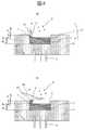
図1の実施例において、頂点部1は、頂点部以外の表面2に対してz方向に突き出している構造とした。このようにした場合、散乱体中の電荷は、突き出していないときに比べより小さな領域に集中するので(xy方向だけではなく、z方向に対しても幅が狭まっている)電荷密度が上がり、近接場光強度を強くすることが出来る。また、このような構造にすれば、図2に示すような作製方法により、頂点部1の材質が異なった構造を容易に作製することが可能になる。すなわち、まず図2(a)のように、基板4の上にレジスト37を塗布し、電子線を照射することにより、三角形の開口部を持つレジストパターンを形成する。次に、図2(b)のように、レジストの開口部における基板表面をReactive Ion Etching装置によりエッチングすることにより、基板4に溝38を形成する。次に、図2(c)のように、散乱体内部となる層3、散乱体の表面層となる層2、及び頂点部1の材質の層34、の3つの層を蒸着装置により成膜する。次に、図2(d)のように、レジストを除去することにより、溝周辺に形成された膜を除去する。最後に、図2(e)のように、頂点部1の材質の層34をイオンミリング装置によりエッチングする。このとき、イオンビーム35を斜めに当てると、頂点部は周囲の影になるため、エッチングされずに残る。これにより、頂点部の材質が異なった構造を容易に作製することが出来る。 In the embodiment of FIG. 1, the
上記実施例において、散乱体32は、基板4表面に埋め込まれるように加工した。もし埋め込まれていない場合、散乱体の頂点部1の側面及び散乱体の内部3の側面にも、塩基伸長酵素が付いてしまう。その結果、複数の塩基伸長酵素が存在するため、単分子測定が困難となる。これに対し、散乱体32を基板4に埋め込めば、側面に塩基伸長酵素が付くことがなく、散乱体の頂点部1表面にのみ塩基伸長酵素を固定することが出来る。 In the above embodiment, the
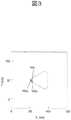
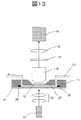
図3に、本実施例の構造により発生する近接場光強度分布の計算結果を示す。観測面は、頂点部から2nm離れた面とした。この図に示すように、頂点近傍に強い近接場光が発生し、そのスポット径は10nm以下となる。頂点部の強度は入射光強度の150倍となるため、その分蛍光強度を強くすることが可能である。 FIG. 3 shows the calculation result of the near-field light intensity distribution generated by the structure of this embodiment. The observation surface was a
上記実施例では、基板4として石英基板を用いたが、光透過性を有するものであれば他の材料でも良く、例えばAl2O3基板を用いても良い。In the above embodiment, a quartz substrate is used as the
上記実施例において、散乱体内部3の材質はAlとしたが、他の材質にしても良く、例えば、Cu,Au,Pt,Tiもしくはそれらの合金などにしても良い。特に、AuやPtなど化学的に安定な材質を用いれば、溶液中に素子を浸けたとき素子が腐食することを防ぐことが出来る。本実施例では、腐食が問題となる溶液に対しては、例えば散乱体内部3の材質としてPtを用いた。このとき、散乱体の長さ(L1)は100nmとし、厚さ(d3)は50nmとした。なお、プラズモン共鳴波長は散乱体の長さ(L1)に依存し、最適な長さは材質ごとに異なる。また厚さ(d3)に関しても、最適な厚さは材質ごとに異なる。したがって、材料ごとに長さや厚さを調整するのが好ましい。In the above embodiment, the material inside the
上記実施例では、塩基伸長酵素5を固定させるための官能基としてチオール基を用いたが、他の官能基を用いても良い。例えばアミノ基、カルボキシル基、ヒドロキシル基、アルデヒド基、ケトン基、NHS−エステル基、イミドエステル基、スルフィジル基、エポキシ基、ヒドラジド基などの官能基を用いても良い。また官能基と塩基伸長酵素をアビジン、ビオチン、デンドロン、クラウンエーテルなどの化合物を介して結合させても良い。このような化合物を用いることにより、塩基伸長酵素の固定化率を上げることが出来る。 In the said Example, although the thiol group was used as a functional group for immobilizing the
上記実施例では、頂点部1及び表面部2の材質は、それぞれAu,Tiとしたが、塩基伸長酵素を固定するのに必要な官能基を頂点部に選択的につけることが出来る組み合わせであれば良く、例えばつぎのような組み合わせにしても良い。 In the above embodiment, the material of the
(1) 頂点部1の材質をAu,Ag,In,Pd,Ru,Zn又はそれらの合金にし、表面部2の材質をAlやCu,Cr又はそれらの合金又はSiO2,TiO2,Al2O3,Cr2O3,ITOなどの誘電体にする。この場合、有機硫黄化合物、有機セレン化合物、又は有機テルル化合物などを反応させることで、塩基伸長酵素を固定するための官能基を、頂点部1に付けることが出来る。(1) The material of the apex 1 is Au, Ag, In, Pd, Ru, Zn or an alloy thereof, and the material of the
(2) 頂点部1の材質をTi,Ni,Cr,Fe,Co,Cd,Al,Ga,In,Nb,Zr,Ta,Hf又はそれらの合金とし、表面部2の材質をAu,Ag,Pt又はそれらの合金にする。この場合、カルボン酸、ホスホン酸、リン酸エステル、有機シラン化合物を反応させることで、塩基伸長酵素を固定するための官能基を、頂点部1に付けることが出来る。(2) The material of the apex 1 is Ti, Ni, Cr, Fe, Co, Cd, Al, Ga, In, Nb, Zr, Ta, Hf or an alloy thereof, and the material of the
なお、散乱体表面層2の材質をTiやCrなどの金属にする場合、その金属層の表面にはTiO2やCr2O3などの酸化膜層が形成されても問題ない。例えば、散乱体表面層2の表面が外気に触れた際、表面には酸化膜が形成される可能性があるが、問題はない。When the material of the
上記実施例では、塩基伸長酵素としてデオキシリボ核酸ポリメラーゼを用いたが、他の酵素を用いても良い。また、塩基伸長酵素を頂点部1に固定することに代えて、図4(a)に示すように、他の物質を介して、検出対象である核酸20を頂点部1に固定しても良い。例えば、検出対象とは異なるDNA、RNA、PNAなどの核酸、又はタンパク質、又は染色体、核様体、細胞膜、細胞壁、ウイルス、抗原、抗体、レクチン、ハプテン、レセプター、ペプチド、スフィンゴ糖、スフィンゴ脂質などを介して、測定対象である核酸を頂点部1に固定させても良い。このような構造を用いる場合、検出対象である核酸20を頂点部1に固定後、塩基伸長酵素5及びヌクレオチド9を溶液中に供給すると、塩基伸長反応が起こり、溶液中のヌクレオチドが、核酸に取り込まれる。取り込まれる際発生する蛍光を観察することにより、塩基配列を知ることが出来る。 In the above embodiment, deoxyribonucleic acid polymerase is used as the base extension enzyme, but other enzymes may be used. Further, instead of fixing the base elongation enzyme to the apex 1, the
図4(b)に示すように、散乱体の頂点部1に半導体微粒子39を配置し、その半導体微粒子39上に塩基伸長酵素5を固定しても良い。この場合、近接場光のエネルギは、まず半導体微粒子39に吸収される。この半導体微粒子39中のエネルギが、双極子相互作用により、ヌクレオチドに固定された色素へ移動し、色素から蛍光が発生する。半導体微粒子を用いない場合、散乱体32に入射しなかった光は、溶液中に進入し、溶液中に浮遊するヌクレオチド9に固定された色素からの発光を誘発する。その発光は、バックグランドとして検出器により検出され、信号の信号/ノイズ比の低下を招く。これに対し、半導体微粒子を用いた場合、入射光の波長は、半導体微粒子の吸収波長に一致させる必要があるが、半導体微粒子の吸収波長と、色素の吸収波長は異なるので、入射光により色素は直接励起されない。したがって、溶液中に浮遊するヌクレオチド9に固定された色素からの発光は生じなく、バックグランド光を低減させる、すなわち信号の信号/ノイズ比を向上させることが出来る。 As shown in FIG. 4 (b),
本実施例では、半導体微粒子として、CdSe微粒子の表面をZnSで覆い、さらにその表面をストレプトアビジンで修飾したもの(インビトロジェン社製品名「Qdot(R)ストレプトアビジン標識」)を用いた。塩基伸長酵素としてデオキシリボ核酸ポリメラーゼを用い、そこにビオチンを付加した。リンカータンパクであるストレプトアビジンにビオチンを結合させることで、塩基伸長酵素と半導体微粒子を結合させた。先端部1の材質はTiとし、そこに上記半導体微粒子を結合させた。 In this example, the surface of the CdSe fine particle was covered with ZnS and the surface was further modified with streptavidin (Invitrogen product name “Qdot (R) streptavidin label”) as the semiconductor fine particle. Deoxyribonucleic acid polymerase was used as a base extension enzyme, and biotin was added thereto. By binding biotin to the linker protein streptavidin, the base extension enzyme and the semiconductor fine particles were bound. The material of the
上記実施例では、散乱体の形状を三角形としたが、近接場光が発生する先鋭化された頂点部を有するものであれば、他の形状でも良く、例えば図5に示すように他の形状にしても良い。図5(a)は、三角形の頂点部が棒状になった形状の実施例を示す。散乱体を構成する膜構成は、図1の実施例と同じとし、散乱体のx方向の長さ(L8)は、100nmとした。棒状になった部分のx方向の長さ(L9)は20nmとし、y方向の幅(L12)は10nmとした。頂点部1の材質が異なった部分のx方向の幅(L5)は10nmとした。入射光の偏光方向はx方向とした。図5(b)の実施例では、散乱体の形状は長軸と短軸の比が3:1の楕円とし、長軸の長さ(L10)は90nmとした。頂点部1の材質が異なった部分のx方向の幅(L5)は10nmとした。図5(c)の実施例では、散乱体の形状は長方形とした。散乱体のx方向の長さ(L11)は30nm、y方向の長さ(L12)は10nmとし、頂点部1の材質が異なった部分のx方向の幅(L5)は10nmとした。In the above embodiment, the shape of the scatterer is a triangle, but other shapes may be used as long as they have a sharp apex that generates near-field light. For example, as shown in FIG. Anyway. Fig.5 (a) shows the Example of the shape where the vertex part of the triangle became rod shape. The film configuration constituting the scatterer was the same as that of the example of FIG. 1, and the length (L8 ) in the x direction of the scatterer was 100 nm. The length (L9 ) in the x direction of the rod-shaped portion was 20 nm, and the width (L12 ) in the y direction was 10 nm. The width (L5 ) in the x direction of the portion where the material of the
上記実施例では、散乱体は、3層より構成するとしたが、2層もしくは4層以上より構成しても良い。図6(a)の実施例では、散乱体表面層2の材質を散乱体内部の層3と同じとすることで2層構造とした。頂点部1の層の材質はAuとし、散乱体内部の層3の材質はTiとした。頂点部1の層の厚さ(d1)は3nm、散乱体内部の層3の厚さ(d3)は50nmとした。図6(b)の実施例では、頂点部1の材質を散乱体内部の層3と同じとすることで2層構造とした。頂点部1の層及び散乱体内部の層3の材質はAuとし、散乱体表面層2の材質はTiとした。頂点部から散乱体内部の層3の上面までの厚さ(d5)は10nmとし、散乱体表面層2の厚さ(d2)は7nmとした。図6(c)の実施例では、散乱体内部の層3を2層に分けることで4層構造とした。頂点部1の層の材質はAu、散乱体表面層2の材質をTi、散乱体内部の層3をPt、その下に設けられた別の材質の層31の材質をAlとした。頂点部1の層の厚さ(d1)は3nm、散乱体表面層2の厚さ(d2)は7nm、散乱体内部の層3の厚さ(d3)は10nm、その下の層31の厚さ(d6)は20nmとした。In the above embodiment, the scatterer is composed of three layers, but may be composed of two layers or four or more layers. In the example of FIG. 6A, the material of the
図1の実施例のように散乱体内部の層3の材質をAlとしたとき、ヌクレオチドを含む溶液によりAlが腐食する可能性がある。これは、散乱体内部の層3は散乱体表面層2により覆われているが、散乱体表面層2が薄い場合、部分的に存在する隙間をとおして溶液が進入する可能性があるためである。これに対し、図6(c)の実施例のように、Alの層の上にPt層を設けることにより、溶液がAlの層へ進入することを防ぐことが出来る。 When the material of the
次に、散乱体周辺に遮光膜が形成された場合について説明する。
図7の実施例では、三角形の散乱体周辺に光を反射又は吸収する遮光用の膜7を形成した。図7(a)は上面図、図7(b)は側断面図である。遮光膜7がない場合、散乱体に入射しなかった光は、溶液中に進入し、溶液中に浮遊するヌクレオチド9に固定された色素からの発光を誘発する。その結果、バックグランド光が多く検出されて、信号の信号/ノイズ比が低下する。これに対し、本実施例のように散乱体周辺に遮光膜7を形成すると、散乱体に入射しなかった光が溶液中に進入することを防ぐことが出来、溶液中に浮遊するヌクレオチド9に固定された色素からの発光を抑制することが出来る。本実施例では、遮光膜7の材質をTi、遮光膜7の開口部の形状を散乱体3と同じ形状とした。遮光膜7の厚さは30nmとした。遮光膜7の開口部の幅(L2)は113nmとし、頂点部1と遮光膜のx方向の距離(L3)は3nm、三角形の底辺部と遮光膜の距離(L4)は10nmとした。散乱体の頂点部1と遮光膜のz方向の距離(d4)は5nmとした。Next, a case where a light shielding film is formed around the scatterer will be described.
In the embodiment of FIG. 7, a
図8に、上記のように遮光膜を形成したとき、頂点部1近傍に発生する近接場光の強度分布を示す。この分布は、頂点部1からz方向に2nm離れた面内における強度分布を示す。この図に示すように、頂点部1近傍に発生する近接場光強度は、入射光強度の約400倍となり、遮光膜を配置することにより、頂点部1に発生する近接場光強度は強くなる。遮光膜が導電性を有する材質で出来ている場合、遮光膜の端には、金属プレート頂点に集まる電荷と逆の極性を持つ電荷が集まる。遮光膜が金属プレート頂点に近づくと、金属プレート頂点の電荷と、遮光膜の端の電荷はお互いに引き合うように相互作用する結果、遮光膜と金属プレート頂点の間に強い近接場光が発生すると考えられる。 FIG. 8 shows the intensity distribution of near-field light generated in the vicinity of the apex 1 when the light shielding film is formed as described above. This distribution shows an intensity distribution in a
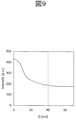
上記導電性を有する遮光膜が形成された構造において、頂点部1と遮光膜7の間の距離D(={(d4)2+(L3)2}1/2)は短い方が、頂点部1に集中した電荷と遮光膜7の端に集中した電荷が、より強く相互作用するため、強い近接場光を発生させることが出来る。図9は、頂点部1と遮光膜7の間の距離Dと近接場光強度の関係を示す。この図に示すように、距離Dが40nm以下になると、遮光膜の存在による近接場光強度の増大が起こる。したがって、距離Dは40nm以下にするのが好ましい。なお、遮光膜を単にバックグランド光の除去を目的に設置する場合は、距離Dは40nm以下でなくても良い。In the structure in which the light shielding film having conductivity is formed, the shorter the distance D (= {(d4 )2 + (L3 )2 }1/2 ) between the
上記導電性を有する遮光膜が形成された構造において、遮光膜の端にも電荷が集まるため、遮光膜の端にも強い近接場光が発生する。塩基伸長酵素5の近傍もしくは頂点部1に固定する核酸の近傍において強い近接場光を発生させるためには、遮光膜7の端(基板側の角)の近傍に塩基伸長酵素もしくは頂点部1に固定する核酸が存在するようにすると良い。そのためには、遮光膜7と頂点部1のz方向の距離d4が、塩基伸長酵素5の寸法もしくは頂点部1に固定する核酸の寸法以下になるようにするのが好ましい。本実施例では、塩基伸長酵素5として、寸法がおよそ10nmのデオキシリボ核酸ポリメラーゼを用いた。したがって、この場合は、距離d4は10nm以下にすることが好ましく、本実施例では、d4=5nmとした。頂点部1と遮光膜7の間の水平方向の距離L3は5nmとした。In the structure in which the light-shielding film having conductivity is formed, charges are collected also at the end of the light-shielding film, so that strong near-field light is also generated at the end of the light-shielding film. In order to generate strong near-field light in the vicinity of the
上記導電性を有する遮光膜が形成された構造において、散乱体の頂点部と反対側のエッジ(三角形の底辺部)33における散乱体と遮光膜の距離(L4)が小さすぎると、散乱体の頂点部と反対側のエッジ33に集中した電荷と遮光膜のエッジに集中した電荷が相互作用する結果、散乱体の頂点部の反対側のエッジ33と遮光膜のエッジの間に、局在した電磁場が発生してしまう。強度は、頂点部に発生する近接場光ほど強くはないが、溶液中に浮遊するヌクレオチド9に固定された色素がこの光により励起され、バックグランド光が発生してしまう可能性がある。この影響を小さくするためには、散乱体の頂点部と反対側(三角形の底辺部)における遮光膜との距離(L4)は、頂点部1と遮光膜7の間のx方向の距離(L3)よりも大きくするのが好ましい。In the structure in which the light-shielding film having conductivity is formed, if the distance (L4 ) between the scatterer and the light-shielding film at the edge (triangle base) 33 opposite to the vertex of the scatterer is too small, the scatterer As a result of the interaction between the charges concentrated on the edge 33 on the side opposite to the apex of the scatterer and the charges concentrated on the edge of the light shielding film, there is a localization between the edge 33 on the opposite side of the vertex of the scatterer and the edge of the light shielding film. Generated electromagnetic field. Although the intensity is not as strong as the near-field light generated at the apex, the dye fixed to the
上記遮光膜の材質は、遮光性を有するものであれば任意であり、Cr,Au,Ptなどの金属にしても良い。また、遮光膜7を金属の膜にすることに換えて、反射率が透過率よりも大きくなるように設計された誘電体多層膜(例えば、Al2O3とSiO2の多層膜)にしても良い。ただし、散乱体頂点部に発生する近接場光を増強するためには、散乱体の材質は、金属などの導電性を有する材料にするのが好ましい。また、遮光膜7の材質が、塩基伸長酵素(もしくは頂点部に固定する核酸)が結合可能な材質である場合、散乱体周辺の開口部において、遮光膜7の側面(開口部の側面)に塩基伸長酵素(もしくは頂点部に固定する核酸)が複数固定される可能性がある。これを防ぐためには、遮光膜7の材質を、散乱体表面層2と同様に、塩基伸長酵素(もしくは頂点部に固定する核酸)が結合しにくい材質にするのが好ましい。The material of the light shielding film is arbitrary as long as it has light shielding properties, and may be a metal such as Cr, Au, or Pt. Further, in place of the
上記実施例では、散乱体の周辺に、遮光を目的に、膜を全面に形成したが、頂点部1に発生する近接場光の強度を強くすることを目的に、頂点部1近傍にのみ導電性を有する膜を形成しても良い。図10は、頂点部1近傍に、長方形の膜8を形成した実施例を示す。図10(a)は上面図、図10(b)は側断面図である。頂点近傍に形成された膜8の材質はTiとし、x方向の幅(L20)を300nm、y方向の幅(L21)を500nm、厚さを30nmとした。散乱体の頂点部1と遮光膜のz方向の距離(d4)は5nmとした。散乱体の形状、材質、寸法は、図1の実施例と同じとした。頂点近傍に形成された膜8のx方向及びy方向の幅は他の値にしても良く、例えば、x方向の幅(L20)を100nm、y方向の幅(L21)を300nm、としても良い。また、実際には、上記散乱体はマトリックス状に配置するため、頂点近傍に形成された膜8もマトリックス状に配置することになるが、y方向の幅(L21)を長くすることにより、頂点近傍に形成された膜8が互いに接合するようにしても良い(例えば、散乱体を1μm間隔で基板上に並べるとき、y方向の幅(L21)を1μm以上とする)。In the above embodiment, the film is formed on the entire surface around the scatterer for the purpose of shielding light. However, in order to increase the intensity of near-field light generated at the apex 1, the film is conductive only near the
上記実施例では、散乱体頂点近傍に形成する膜8の形状は長方形としたが、他の形状にしても良い。例えば、図11に示すように、膜8の形状を三角形にしても良い。この場合、膜8のx方向の長さ(L7)を適当な値にすると、膜8中にもプラズモンが励起され、その頂点部21に強い電荷の集中が起こる。そして、頂点部21に集中した電荷と、散乱体の頂点部1に集中した電荷の相互作用により、2つの頂点の間により強い近接場光を発生させることが出来る。本実施例では、膜8の材質はTi、x方向の長さ(L7)は90nm、厚さは30nmとした。散乱体の形状、材質、寸法は、図1の実施例と同じとした。In the above embodiment, the shape of the
以下、核酸分析装置の実施例について記載する。
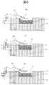
図12は、核酸分析装置の構成図を示す。本実施例では、基板4上に図1に示されるような三角形の形状をした散乱体を、図12(b)に示すように、マトリックス状に配置した。散乱体は、x方向に4000個、y方向に3000個並べた。x方向のピッチ(px)は1μm、y方向のピッチ(py)も1μmとした。散乱体の総数は1200万個で、散乱体が存在する領域のx方向の幅W10=4mm、y方向の幅W11=3mmである。散乱体が形成された基板4の上には、薬液を供給するための反応チャンバ11をかぶせた。図13に示すように、反応チャンバ11には、薬液を流すための溝27及び検出窓12を形成した。反応チャンバ11と基板4の間から薬液が漏れないように、溝27の周辺にはOリング36を配置した。核酸、反応酵素、バッファー、ヌクレオチド等の溶液は薬液タンク25内に保存し、そこから薬液供給用配管13を通して、反応チャンバ11内に形成された溝27に注入した。薬液タンク25の温度は、温度制御器により制御した。薬液供給用配管13内を流れる液体の流量は、バルブ24により制御した。廃液は、薬液排出用配管23を通して、廃液タンク26内に回収した。薬液を流すための溝27のx,y方向の幅は8mm×8mmとし、散乱体すべての表面が薬液に浸されるようにした。反応チャンバの材質は、PDMS(Polydimethylsiloxane)等の樹脂とした。検出窓12の材質はガラスとし、厚さは0.17mmとした。Hereinafter, examples of the nucleic acid analyzer will be described.
FIG. 12 shows a configuration diagram of the nucleic acid analyzer. In this embodiment, the scatterers having a triangular shape as shown in FIG. 1 are arranged on the
図13に示すように、色素を励起するための光は、基板4の裏側から垂直に入射させた。光源14としては、YAGレーザ(波長532nm、出力20mW)を用い、その光のスポット径をレンズ15により調整し、レーザ光が散乱体全面に照射されるようにした。ヌクレオチドが核酸に取り込まれた際発生する蛍光は、検出窓12を通して検出した。蛍光は、対物レンズ16により平行光にした後、結像レンズ18により集光し、CCDカメラ19等の撮像装置により検出した。対物レンズ16と結像レンズ18の間には、発生する蛍光波長のみ透過するフィルタ17を配置することで、励起光がCCDカメラ19に入射することを防いだ。各散乱体から発生する蛍光は、CCDカメラ19によりリアルタイムに検出した。蛍光色素の種類は、CCDに映された蛍光色の違いにより識別した。 As shown in FIG. 13, the light for exciting the dye was vertically incident from the back side of the
上記実施例では、入射光は基板4に対し垂直に入射させたが、斜めに入射させても良い。図14は、プリズムを利用して入射光を斜めに入射させた場合の実施例を示す。この実施例では、光源14としては、YAGレーザ(波長532nm、出力20mW)を用い、レーザ14からの出射光をレンズ15により平行光にし、プリズム29に入射させた。プリズム29の上には、核酸検出素子が形成された基板10を配置し、基板10の表面で入射光が全反射するようにした。蛍光の検出は、図13の実施例と同様に、基板10の反対側に設置された対物レンズ16及びCCDカメラ19を用いて行った。図13のように、基板に垂直に光を入射させる場合、近接場光に変換されなかった光は、溶液中に進み、溶液中の色素からの蛍光(バックグランド光)を発生させてしまう。これに対し、プリズム29を用いる場合、入射光はプリズム表面で全反射するため、溶液中に進入する入射光の量は小さくなる。その結果、バックグランド光の検出を抑えることが出来る。 In the above embodiment, the incident light is incident on the
1 頂点部
2 散乱体表面層
3 散乱体内部
4 基板
5 塩基伸長酵素
6 入射光
7 遮光膜
8 頂点近傍に形成された金属膜
9 色素が結合したヌクレオチド
10 核酸検出素子が形成された基板
11 反応チャンバ
12 検出窓
13 薬液供給用配管
14 レーザ
15 レンズ
16 対物レンズ
17 フィルタ
18 結像レンズ
19 CCDカメラ
20 核酸
21 頂点部
22 マトリックス状に並べられた核酸検出素子
23 薬液排出用配管
24 バルブ
25 薬液タンク
26 廃液タンク
27 薬液を流すための溝
29 プリズム
31 散乱体内部に設けられた別の材質の層
32 導電性を有する散乱体
33 頂点と反対側のエッジ
34 頂点部と同じ材質の層
35 イオンビーム
36 Oリング
37 レジスト
38 溝
39 半導体微粒子DESCRIPTION OF
Claims (10)
Translated fromJapanese前記頂点部に固定された塩基伸長反応を促進するための酵素もしくは核酸と、を備え、
前記頂点部は前記導電性散乱体の表面から突出しており、
前記頂点部は前記酵素もしくは前記核酸を固定させるのに必要な官能基が形成可能な材料からなり、前記導電性散乱体の前記頂点部以外は前記官能基を形成出来ない材料からなり、
前記平面状の導電性散乱体に垂直な方向から光を入射することによってプラズモンを発生させ、前記頂点部に近接場光が発生するように構成されていることを特徴とする核酸分析素子。Aplanar triangular conductive scatterer having a vertex that generates near-field light;
An enzyme or a nucleic acid for promoting a base extension reaction fixed to the apex part,
The apex part protrudes from the surface of the conductive scatterer,
The apex part is made of a material capable of forming a functional group necessary for immobilizing the enzyme or the nucleic acid, and is made of a material that cannot form the functional group other than the apex part of the conductive scatterer,
A nucleic acid analyzing elementconfigured to generate plasmons by entering light from a direction perpendicular to the planar conductive scatterer and to generate near-field light at the apex .
前記核酸分析素子を光照射する光源と、
前記核酸分析素子から発生された蛍光を撮像する撮像装置と、
蛍光色素が結合したヌクレオチドを含む溶液を前記核酸分析素子の表面に供給する手段と、を備え
前記核酸分析素子は、表面に凹部が形成された透明基板と、前記凹部の中に配置された近接場光を発生する頂点部を有する平面状の三角形の導電性散乱体と、前記頂点部に固定された塩基伸長反応を促進するための酵素もしくは核酸とを有し、前記頂点部は前記導電性散乱体の表面から突出しており、前記頂点部は前記酵素もしくは前記核酸を固定させるのに必要な官能基が形成可能な材料からなり、前記導電性散乱体の前記頂点部以外は前記官能基を形成出来ない材料からなり、前記平面状の導電性散乱体に垂直な方向から光を入射することによってプラズモンを発生させ、前記頂点部に近接場光が発生するように構成されていることを特徴とする核酸分析装置。A nucleic acid analysis element;
A light source for irradiating the nucleic acid analysis element;
An imaging device for imaging fluorescence generated from the nucleic acid analysis element;
Means for supplying a solution containing nucleotides to which a fluorescent dye is bound to the surface of the nucleic acid analysis element, the nucleic acid analysis element comprising a transparent substrate having a recess formed on the surface, and a proximity disposed in the recess a conductive scattererplanar triangle with an apex for generating a field light,possess an enzyme or nucleic acids to facilitate a fixed base extension reaction to said apexportion, said apex portion is the conductive It protrudes from the surface of the scatterer, and the apex part is made of a material capable of forming a functional group necessary for immobilizing the enzyme or the nucleic acid, and the functional group other than the apex part of the conductive scatterer has the functional group. It is made of a material that cannot be formed, and is configured to generate plasmons when light enters from a direction perpendicular to the planar conductive scatterer, and to generate near-field light at the apex portion. A nucleic acid analyzer.
Priority Applications (1)
| Application Number | Priority Date | Filing Date | Title |
|---|---|---|---|
| JP2009187435AJP5462548B2 (en) | 2009-08-12 | 2009-08-12 | Nucleic acid analyzer and nucleic acid analyzer using the same |
Applications Claiming Priority (1)
| Application Number | Priority Date | Filing Date | Title |
|---|---|---|---|
| JP2009187435AJP5462548B2 (en) | 2009-08-12 | 2009-08-12 | Nucleic acid analyzer and nucleic acid analyzer using the same |
Publications (2)
| Publication Number | Publication Date |
|---|---|
| JP2011038932A JP2011038932A (en) | 2011-02-24 |
| JP5462548B2true JP5462548B2 (en) | 2014-04-02 |
Family
ID=43766857
Family Applications (1)
| Application Number | Title | Priority Date | Filing Date |
|---|---|---|---|
| JP2009187435AExpired - Fee RelatedJP5462548B2 (en) | 2009-08-12 | 2009-08-12 | Nucleic acid analyzer and nucleic acid analyzer using the same |
Country Status (1)
| Country | Link |
|---|---|
| JP (1) | JP5462548B2 (en) |
Families Citing this family (2)
| Publication number | Priority date | Publication date | Assignee | Title |
|---|---|---|---|---|
| CA2930836A1 (en) | 2013-11-17 | 2015-05-21 | Quantum-Si Incorporated | Active-source-pixel, integrated device for rapid analysis of biological and chemical specimens |
| US12078596B2 (en) | 2017-07-24 | 2024-09-03 | Quantum-Si Incorporated | Hand-held, massively-parallel, bio-optoelectronic instrument |
Family Cites Families (4)
| Publication number | Priority date | Publication date | Assignee | Title |
|---|---|---|---|---|
| JP3882456B2 (en)* | 2000-03-13 | 2007-02-14 | 株式会社日立製作所 | Near-field optical probe, near-field optical microscope and optical recording / reproducing apparatus using the same |
| EP2027442A2 (en)* | 2006-05-16 | 2009-02-25 | Applied Biosystems, Inc. | Systems, methods, and apparatus for single molecule sequencing |
| JP5222599B2 (en)* | 2007-07-20 | 2013-06-26 | 株式会社日立ハイテクノロジーズ | Nucleic acid analysis device and nucleic acid analysis apparatus using the same |
| JP2009080011A (en)* | 2007-09-26 | 2009-04-16 | Fujifilm Corp | Fluorescence detection method |
- 2009
- 2009-08-12JPJP2009187435Apatent/JP5462548B2/ennot_activeExpired - Fee Related
Also Published As
| Publication number | Publication date |
|---|---|
| JP2011038932A (en) | 2011-02-24 |
Similar Documents
| Publication | Publication Date | Title |
|---|---|---|
| US8835185B2 (en) | Target substance-detecting element | |
| CN101393123B (en) | Apparatus and method for detecting target substance, or device used for these apparatus and method | |
| JP5222599B2 (en) | Nucleic acid analysis device and nucleic acid analysis apparatus using the same | |
| JP3897703B2 (en) | Sensor device and inspection method using the same | |
| JP5820929B2 (en) | SPR sensor device with nanostructure | |
| JP5152917B2 (en) | Detection method, detection sample cell and detection kit | |
| JP5143668B2 (en) | Detection method, detection sample cell and detection kit | |
| JP4974870B2 (en) | Optical element, sensor device and sensing method | |
| JP2011503536A (en) | Microelectronic sensor | |
| JP5328915B2 (en) | High sensitivity fluorescence detection device | |
| US20200256794A1 (en) | Nanoplasmonic devices and applications thereof | |
| CN102798615A (en) | Periodic nanostructure-based biosensor and preparation method thereof | |
| US8865403B2 (en) | Nucleic acid analyzing device and nucleic acid analyzer | |
| JP2005345402A (en) | Measuring device using surface plasmon resonance and analyzer using the same | |
| CN103018167A (en) | Surface plasma resonance sample table and preparation method thereof | |
| JP5462548B2 (en) | Nucleic acid analyzer and nucleic acid analyzer using the same | |
| CN1971267A (en) | Waveguide-Coupled Surface Plasmon Resonance Biosensors | |
| WO2015146036A1 (en) | Enhanced raman spectroscopy device | |
| US20110195516A1 (en) | Wire grid substrate structure and method for manufacturing such a substrate | |
| JP5831230B2 (en) | Surface plasmon enhanced fluorescence measurement device | |
| WO2014007134A1 (en) | Sensor chip | |
| Urbancova et al. | IP-Dip-Based SPR Structure for Refractive Index Sensing of Liquid Analytes. Nanomaterials 2021, 11, 1163 | |
| Ding | Compact Sensing Platforms Based on Localized Surface Plasmon Resonance | |
| JP2008232721A (en) | Optical element, sensor device, and optical element manufacturing method | |
| JP2012251863A (en) | Surface plasmon excitation enhanced fluorescence measuring device and sensor structure to be used for the same |
Legal Events
| Date | Code | Title | Description |
|---|---|---|---|
| A621 | Written request for application examination | Free format text:JAPANESE INTERMEDIATE CODE: A621 Effective date:20120210 | |
| A977 | Report on retrieval | Free format text:JAPANESE INTERMEDIATE CODE: A971007 Effective date:20130531 | |
| A131 | Notification of reasons for refusal | Free format text:JAPANESE INTERMEDIATE CODE: A131 Effective date:20130604 | |
| A521 | Written amendment | Free format text:JAPANESE INTERMEDIATE CODE: A523 Effective date:20130730 | |
| TRDD | Decision of grant or rejection written | ||
| A01 | Written decision to grant a patent or to grant a registration (utility model) | Free format text:JAPANESE INTERMEDIATE CODE: A01 Effective date:20140107 | |
| A61 | First payment of annual fees (during grant procedure) | Free format text:JAPANESE INTERMEDIATE CODE: A61 Effective date:20140117 | |
| R150 | Certificate of patent or registration of utility model | Ref document number:5462548 Country of ref document:JP Free format text:JAPANESE INTERMEDIATE CODE: R150 Free format text:JAPANESE INTERMEDIATE CODE: R150 | |
| S531 | Written request for registration of change of domicile | Free format text:JAPANESE INTERMEDIATE CODE: R313531 | |
| S533 | Written request for registration of change of name | Free format text:JAPANESE INTERMEDIATE CODE: R313533 | |
| R350 | Written notification of registration of transfer | Free format text:JAPANESE INTERMEDIATE CODE: R350 | |
| LAPS | Cancellation because of no payment of annual fees |