JP5460211B2 - Multifocal intraocular lens - Google Patents
Multifocal intraocular lensDownload PDFInfo
- Publication number
- JP5460211B2 JP5460211B2JP2009224114AJP2009224114AJP5460211B2JP 5460211 B2JP5460211 B2JP 5460211B2JP 2009224114 AJP2009224114 AJP 2009224114AJP 2009224114 AJP2009224114 AJP 2009224114AJP 5460211 B2JP5460211 B2JP 5460211B2
- Authority
- JP
- Japan
- Prior art keywords
- intraocular lens
- diffraction
- optical unit
- multifocal intraocular
- focus
- Prior art date
- Legal status (The legal status is an assumption and is not a legal conclusion. Google has not performed a legal analysis and makes no representation as to the accuracy of the status listed.)
- Expired - Fee Related
Links
- 230000003287optical effectEffects0.000claimsdescription61
- 210000001747pupilAnatomy0.000claimsdescription19
- 230000004438eyesightEffects0.000description26
- 208000001491myopiaDiseases0.000description17
- 239000000463materialSubstances0.000description6
- 230000002093peripheral effectEffects0.000description6
- 238000004364calculation methodMethods0.000description5
- 229920003229poly(methyl methacrylate)Polymers0.000description4
- 239000004926polymethyl methacrylateSubstances0.000description4
- 238000004088simulationMethods0.000description4
- 206010027646MiosisDiseases0.000description3
- 238000000034methodMethods0.000description3
- 208000006550MydriasisDiseases0.000description2
- -1acrylic esterChemical class0.000description2
- 238000010586diagramMethods0.000description2
- 230000003547miosisEffects0.000description2
- JHPBZFOKBAGZBL-UHFFFAOYSA-N(3-hydroxy-2,2,4-trimethylpentyl) 2-methylprop-2-enoateChemical compoundCC(C)C(O)C(C)(C)COC(=O)C(C)=CJHPBZFOKBAGZBL-UHFFFAOYSA-N0.000description1
- 208000002177CataractDiseases0.000description1
- 208000010415Low VisionDiseases0.000description1
- 239000004642PolyimideSubstances0.000description1
- 239000004743PolypropyleneSubstances0.000description1
- 101150105133RRAD geneProteins0.000description1
- 239000002131composite materialSubstances0.000description1
- 230000004301light adaptationEffects0.000description1
- 230000004048modificationEffects0.000description1
- 238000012986modificationMethods0.000description1
- 238000000465mouldingMethods0.000description1
- 229920001721polyimidePolymers0.000description1
- 229920001155polypropylenePolymers0.000description1
- 229920001296polysiloxanePolymers0.000description1
- 239000011347resinSubstances0.000description1
- 229920005989resinPolymers0.000description1
- 230000002207retinal effectEffects0.000description1
- 239000000126substanceSubstances0.000description1
- 238000001356surgical procedureMethods0.000description1
- 230000004304visual acuityEffects0.000description1
- 230000000007visual effectEffects0.000description1
- XLYOFNOQVPJJNP-UHFFFAOYSA-NwaterSubstancesOXLYOFNOQVPJJNP-UHFFFAOYSA-N0.000description1
Images


Landscapes
- Prostheses (AREA)
Description
Translated fromJapanese本発明は、患者眼の眼内に設置する眼内レンズに複数の焦点を持たせた多焦点眼内レンズに関する。The present invention relates tomultifocal intraocular lenses which gave multiple focus intraocular lens placed in the eye of the patient's eye.
白内障の手術で摘出された水晶体の代わりに眼内に挿入される眼内レンズとしては、光学部への入射光を単一の焦点に集光させる単焦点眼内レンズが知られている。また、近年光学部への入射光を複数の焦点に振り分けて集光させ、被検者眼に擬似的な調節力を与えることができる多焦点眼内レンズが知られている。このような多焦点眼内レンズとしては、光学部のベースカーブ上に形成された回折領域によって入射光を異なる複数の焦点に振り分ける回折型の多焦点眼内レンズが知られている(例えば、特許文献1参照)。 As an intraocular lens that is inserted into the eye instead of the lens that has been removed by cataract surgery, a single-focus intraocular lens that collects light incident on the optical unit at a single focal point is known. In recent years, multifocal intraocular lenses have been known that can divide and collect light incident on an optical unit into a plurality of focal points to give a pseudo adjustment force to a subject's eye. As such a multifocal intraocular lens, a diffractive multifocal intraocular lens that distributes incident light to a plurality of different focal points by a diffractive region formed on a base curve of an optical unit is known (for example, a patent) Reference 1).
ところで、一般的な生活環境においては、近くのものを見る場合(近方視)よりも遠くのものを見ている場合(遠方視)が多い。また、眼の瞳孔は近くを見るときは小さくなり、遠くを見るときは大きくなる傾向が知られている。そのため、従来の回折型の多焦点眼内レンズは、光学部の中心付近(光軸の周辺)に形成された回折領域によって近方視を行わせ、光学部の周縁には回折領域を設けずに遠方視を重視させる設計がされている場合が多い。 By the way, in a general living environment, there are more cases of looking at a far object (far vision) than when viewing a near object (near vision). In addition, it is known that the pupil of the eye tends to be small when looking near and large when looking far. Therefore, the conventional diffractive multifocal intraocular lens performs near vision by a diffraction region formed near the center of the optical unit (around the optical axis), and does not provide a diffraction region at the periphery of the optical unit. Are often designed to emphasize distance vision.
しかしながら、眼の瞳孔径の大きさには個人差があり、瞳孔径が小さい被検者にとっては、このような構成の多焦点眼内レンズでは効果的に遠方視が行い難い場合がある。また、同一の被検者でも周囲の明るさ等の変化によって瞳孔の大きさは変わるので、遠方視が行い難くなる状況が発生する。日常生活で重視される遠方視が行い難くなることは被検者にとって不便である。 However, there are individual differences in the size of the pupil diameter of the eye, and it may be difficult for a subject with a small pupil diameter to effectively perform far vision with a multifocal intraocular lens having such a configuration. In addition, even in the same subject, the size of the pupil changes due to changes in ambient brightness and the like, so that it becomes difficult to perform far vision. It is inconvenient for the subject that it is difficult to perform distant vision that is important in daily life.
本発明は、上記従来技術の問題点に鑑み、瞳孔径の大きさに関わらず遠方視に適した多焦点眼内レンズを提供することを技術課題とする。In view of the above problems of the prior art, it is an object of the present invention to provide amultifocal intraocular lens suitable for far vision regardless of the size of the pupil diameter.
上記課題を解決するために、本発明は以下のような構成を備えることを特徴とする。 In order to solve the above problems, the present invention is characterized by having the following configuration.
(1) 入射光の一部を屈折力により所定の遠用焦点に集光させるためのベースカーブを持つ光学部と、前記光学部の前記ベースカーブを形成するレンズ面に同心円状に形成される複数の回折格子によりなり前記光学部に所定の加入度を与えるための回折領域であって、位相差により各ステップ高さが決定される前記複数の回折格子の回折によって入射光の一部を所定の近用焦点に集光させるための回折領域と、を備える多焦点眼内レンズであって、前記回折領域に形成される全ての回析格子の各ステップ高さは、前記位相差を0.2以上0.45以下として全て一定の高さで形成され、前記回折領域は被検者眼の瞳孔径によらず前記入射光を一定の比率で前記近用焦点よりも前記遠用焦点に多く配分させるように構成されている、ことを特徴とする。
(1) An optical part having a base curve for condensing a part of incident light to a predetermined distance focus by refractive power and alens surface forming the base curve of the optical part are formed concentrically. A diffraction region composed of a plurality of diffraction gratings for giving a predetermined addition to the optical unit, wherein a part of incident light is predetermined by diffraction of the plurality of diffraction gratings, each step height being determined by a phase difference A multifocal intraocular lens having a diffractive region for condensing at a near focal point of each of the diffractive regions. 2 and 0.45 or less, all of which are formed at a constant height, and the diffractive region has a greater proportion of the incident light at the far focus than the near focus at a constant ratio regardless of the pupil diameter of the subject's eye. Characterizedby being configured to distribute And
瞳孔径の大きさに関わらず遠方視に適した回折型の多焦点眼内レンズを提供できる。 It is possible to provide a diffractive multifocal intraocular lens suitable for far vision regardless of the size of the pupil diameter.
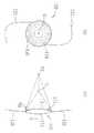
以下、本発明の実施の形態を図面に基づいて説明する。図1は本実施形態で用いる眼内レンズ(多焦点眼内レンズ)の概略図であり、図1(a)は正面図、図1(b)は側面図である。眼内レンズ100は所定の屈折力を有し、眼内に置いたときに角膜側となる前面111と、網膜側となる後面112を供える光学部110と、光学部110を患者眼の眼内にて固定支持するための一対の支持部120とからなる。なお、図1では、前面111と後面112の両面が凸面で形成されているが、前面111と後面112は凸面、凹面又は平面の組合せで構成する事が出来る。
光学部110は、PMMA(ポリメチルメタクリレート)等の硬い材料や、シリコーン等の単体、又は、アクリル酸エステルとメタクリル酸エステルの複合材料からなる折り曲げ可能な材料から形成される。Hereinafter, embodiments of the present invention will be described with reference to the drawings. FIG. 1 is a schematic view of an intraocular lens (multifocal intraocular lens) used in this embodiment, FIG. 1 (a) is a front view, and FIG. 1 (b) is a side view. The
The
光学部110の前面111には、光学部110と回折領域150が形成されている。本実施形態では、回折領域150は前面111の全域に形成するものとしている。なお、回折領域150と光学部110とは、金型などにより一体的に成形したり、切削加工により形成することができる。詳細は後述するが、光学部110が持つ屈折率と曲率とによって得られる屈折度数に、回折領域150により発生する加入度が加えられることによって、眼内レンズ100に複数の焦点が与えられる。本実施形態では、遠くを見るための遠用焦点(遠用度数)と近くを見るための近用焦点(近用度数)とが与えられる。 An
回折領域150は、光軸Oを中心として同心円状に形成された複数の輪体151により構成されている。ここでは、各輪体151は鋸歯状の断面形状を有しており、隣合う輪体151の境界には回折格子152が形成されている(図3参照)。回折格子152は光学部110に入射する入射光の一部を回折させることにより、近方視のための近方焦点を得る役割を有する。なお、回折領域150は好ましくは光学部110の前面111に形成されるが、後面112、又は前面111と後面112の両面に形成されても良い。 The
支持部120はその一端(基端)が光学部側110に接合され、他端(先端)を自由端としたループ形状を有している。支持部120は、PMMA(ポリメチルメタクリレート)、ポリプロピレン、ポリイミド等の樹脂にて形成される。支持部120は、図1(b)に示すように、光学部110の前面111に対し所定の角度(例えば、0〜10度程度)を持つように接合されている。これにより光学部110の後面112が嚢内で押し付けられた状態で好適に配置されるようになる。 The
なお、図1では、光学部110と支持部120とが別々に形成された後に一体化されるスリーピースタイプの眼内レンズを例に挙げているが、これ以外にも本発明は、同一素材の光学部110と支持部120とが切削加工、モールディング加工により一体的に形成されるワンピース型の眼内レンズにも適用することができる。 In FIG. 1, a three-piece type intraocular lens that is integrated after the
以上のような構成を備える眼内レンズ100の最外径(最大全長)は、嚢内に眼内レンズ100が設置された際に支持部120の外側から内側に向かって好適な応力がかかる程度の大きさとされ、好ましくは9mm以上15mm以下である。光学部110の直径は、瞳孔の大きさに基づいて設定され、好ましくは4.25mm以上7mm以下とされる。支持部120はこれらの条件を満足するように長さ及び形状が設定される。 The outermost diameter (maximum total length) of the
次に、眼内レンズ100に所定の遠用度数及び近用度数を与えるための設計方法を説明する。はじめに、光学部110の屈折力(屈折度数)により遠用度数が決定される。例えば、光学部110の屈折度数(ディオプター)は1D〜30Dの範囲において必要とされる屈折度数が設定される。なお、光学部110の屈折力は、光学部110を構成する材料の屈折率、及び前後面のカーブ(曲率)によって決定される。 Next, a design method for giving the intraocular lens 100 a predetermined distance power and near power will be described. First, the distance power is determined by the refractive power (refractive power) of the
次に、回折領域150の設計により光学部110に与えられる加入度が決定される。例えば、回折領域150による加入度は2D〜4Dの範囲において必要とされる加入度となるように設計される。例えば、遠用度数として1D〜30Dが設定されていれば、眼内レンズ100に3D〜34Dの近用度数が設定されることとなる。 Next, the addition given to the
以下に、回折領域150により所定の加入度を得るための設計方法を説明する。図2は光学部110を側面から見たときの前面111付近を模式的に示している。ここでは、z軸は光学部110の光軸Oに、y軸は光学部110の径方向に一致している。光学部110のベースカーブとなる曲面C上に同心円状に配置される回折格子152の光軸Oからの距離ri(i=0、1、2、3、…n)は次式で求められる。 Hereinafter, a design method for obtaining a predetermined addition power by the

ここで、iは光軸Oからの回折格子152の数、λは設計波長(光学設計の基準となる
色の波長)、fは近方視のために加算される屈折度数を焦点距離にて示している。例えば、設計波長λは明順応においける視覚応答の中心に位置する555nm(緑色)、加入度を4Dとするならば焦点距離fは250mmに設定される。Here, i is the number of
式1によって設定した加入度を得るために必要とされる曲面C上に配置される回折格子152の光軸Oからの距離r0、r1、r2、・・・rnが決定され、これにより曲面C上の回折格子の位置p0、p1、p2、p3、・・・pnが決定される。 The distances r0, r1, r2,... Rn from the optical axis O of the diffraction grating 152 arranged on the curved surface C required to obtain the addition set by the
また、遠方視と近方視に寄与する光量の配分は、回折格子152の高さ(ステップ高さ)で決定される。回折格子152の高さhは次式で求められる。 Further, the distribution of the amount of light that contributes to far vision and near vision is determined by the height (step height) of the diffraction grating 152. The height h of the diffraction grating 152 is obtained by the following equation.
ここでは、設計波長λは555nm、光学部110の材料の屈折率n2は1.52、周辺媒質(水)の屈折率n1は1.336である。位相差Pは入射光の光量を遠方視と近方視とに振り分けるためのパラメータであり、位相差Pにより回折格子152の高さが決定される。本実施形態において位相差Pは、回折格子152による回折により近用焦点よりも遠用焦点に集光される光量の配分(回折効率)が高くなるような値に設定される。回折効率の演算の詳細な説明は後述する。 Here, the design wavelength λ is 555 nm, the refractive index n2 of the material of the
回折格子152の位置pn(n=0、1、2、3、・・・n)と位相差Pに基づく高さhが決定したら、隣合う回折格子152の上端と下端とを繋ぐことで輪体151の外形形状が形作られる。なお高さhはベースカーブとされる曲面Cを中間位置として上下方向に均等に配分される。また、本実施形態では輪体151の外形形状とされる面は、光学部110の光軸上に中心座標を持つ所定の曲率をもった曲面としている。 When the position pn (n = 0, 1, 2, 3,... N) of the
図3は輪体151を設計するための説明図である。ここで、一つの輪体151の開始位置Pa,終了位置Pbとすると、光軸O上に設定される輪体151の曲面C2の中心座標Zradは次式により求められる。 FIG. 3 is an explanatory diagram for designing the
ここで、raは輪体151の開始位置Paでの半径、rbは終了位置Pbでの半径、zaは輪体151の開始位置Paのz座標、zbは終了位置Pbのz座標である。輪体151の曲面C2の中心座標Zradが決定されたら、輪体151の曲面C2の曲率半径Rradは次式で求められる。 Here, ra is the radius at the start position Pa of the
これにより、回折領域150に形成される輪体151の形状が決定される。なお、ここでは、開始位置Paと終了位置Pbとが曲面C2で接続される場合を示したが、これ以外にも、開始位置Paと終了位置Pbとを階段状の形状又は直線で接続されることで輪体151が形作られるようにしても良い。 As a result, the shape of the
ところで、入射光を遠方視と近方視とに振り分けるための比率である回折効率ηmは次式で求められる。 By the way, the diffraction efficiency ηm, which is a ratio for distributing incident light into far vision and near vision, is obtained by the following equation.
ここで、位相差Pは前述と同様である。回折次数mは回折格子152により回折された光の方向を示し、遠方視の場合は回折をせずに通過するのみであるので0次(m=0)、近方視の場合は1次(m=1)である。レベル数Nは輪体151の曲面C2の滑らかさを示し、曲面C2が滑らかで有るほどレベル数Nの値は大きくなる。例えば、曲面の場合のレベル数Nは1E+20(1020)に設定される。Here, the phase difference P is the same as described above. The diffraction order m indicates the direction of the light diffracted by the
図4は上式を用いて、設計波長と使用波長が同一の場合において、位相差P毎に遠方視の回折効率η0と近方視の回折効率η1を求めた演算結果である。図4から、位相差Pを0.5よりも小さくすると、近方焦点に対する回折効率η1に比べて、遠方焦点への回折効率η0がより大きくなり、光量の配分が多くなることが分かる。 FIG. 4 shows the calculation results of obtaining the far vision diffraction efficiency η0 and the near vision diffraction efficiency η1 for each phase difference P when the design wavelength and the use wavelength are the same. From FIG. 4, it can be seen that when the phase difference P is smaller than 0.5, the diffraction efficiency η0 to the far focus is larger than the diffraction efficiency η1 to the near focus, and the light quantity distribution is increased.
したがって、位相差Pは0.2〜0.45に設定されれば良い。より好ましくは、位相差Pは0.3〜0.45に設定される。なお、位相差Pが0.2よりも小さいと近方焦点に集光される光量が少なくなり近方視がされにくくなる。一方、位相差Pが0.5よりも大きくなると遠方焦点よりも近方焦点への光量の配分が多くなり、遠方視がし辛くなる。 Therefore, the phase difference P may be set to 0.2 to 0.45. More preferably, the phase difference P is set to 0.3 to 0.45. If the phase difference P is smaller than 0.2, the amount of light collected at the near focus is reduced, and near vision is difficult to be achieved. On the other hand, when the phase difference P is larger than 0.5, the amount of light is more distributed to the near focus than the far focus, making it difficult to view far.
以上のように設計された回折領域150の回折格子152に入射光が当たると、位相差Pの設定に応じて入射光の一部が回折されて近用焦点f1へと集光される。一方、入射光の他の一部は光学部110の屈折力により屈折されて遠用焦点f2へと集光される(図1(b)参照)。これにより、被検者は近方視と遠方視の両方が得られる。 When the incident light hits the
また、ここでは、回折格子152の高さhは、回折格子152の位置pi(i=0、1
、2、3、…、n)に関わらず一定の高さに設定されている。そのため、遠用焦点と近用焦点とに振り分けられる入射光の配分も光学部110の中央部と周辺部とで一定となる。その為、被検者眼の散瞳又は縮瞳により瞳孔径が変わったとしても常に一定の見易さでの遠方視が出来るようになる。また、瞳孔径の大きさの個人差に関わらず遠方視がし易い状態が保たれる。Further, here, the height h of the
2, 3,..., N) is set to a constant height. For this reason, the distribution of incident light distributed to the far focus and the near focus is also constant between the central portion and the peripheral portion of the
以上のように、近用焦点に比べて遠用焦点に集光される入射光の配分が大きくなるように位相差Pが決定されることで、回折格子152による入射光の回折により、被検者眼の瞳孔径の状態(縮瞳、散瞳、瞳孔のサイズの個人差)に関わらずより明瞭な遠方視力を与えることができるようになる。 As described above, the phase difference P is determined so that the distribution of the incident light condensed on the far focus is larger than that on the near focus. Regardless of the pupil diameter state (miosis, mydriasis, and individual differences in pupil size) of the human eye, clearer visual acuity can be given.
ところで、上記の説明では、光学部110の前面111の全体に回折領域150が配置される場合を説明したが、回折領域150は前面111の光軸Oから所定の範囲内で形成されるようにしても良い。遠方視では瞳孔が開いた状態になるため、光学部110の外周部に回折領域150を配置せず、外周部を単焦点レンズとして機能させても、瞳孔径の大きさに関わらず常に快適な遠方視を行う事ができるようになる。 By the way, in the above description, the case where the
図5に光学部110の変容例を示す。図5(a)は正面図、図5(b)は側面図である。ここでは、光学部110の外周端面から所定の範囲(外周部)dで回折領域150を取り除いている。なお、この場合も(式2)によって決定される各回折格子152の高さhは、位相差Pにより入射光がより遠用焦点により集光されるような高さに設定されている。 FIG. 5 shows a modification example of the
<実施例1>
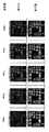
図6に瞳孔径の変化に伴う有効レンズ径毎に行った遠方視と近方視の見え方のシミュレーション結果を示す。ここでは、遠用度数が20D、加入度が4D(これによる近用度数が24D)に設計された眼内レンズ100を想定してシミュレーションを行った。上段は遠方視、下段は近方視の見え方のシミュレーション結果である。左側からそれぞれレンズ径の大きさを2mm、3mm、・・・6mmに設定した場合の結果を示しており、レンズ径(瞳孔径)の大きさの違いによる見え方の変化を比較している。<Example 1>
FIG. 6 shows a simulation result of how far vision and near vision are seen for each effective lens diameter accompanying the change in pupil diameter. Here, the simulation was performed on the assumption that the
光学部110の演算条件は、光学材料の屈折率n2=1.52、前面111の曲率18.2mm、後面112の曲率18.2mm、レンズ径が6.0mmである。回折領域150の演算条件は光学材料の屈折率n2=1.52、周辺媒質の屈折率n1=1.336、設計波長λ=555nm、使用波長λ=555nm、近方視の焦点距離f=250mm、位相差P=0.4であり、これにより回折格子152の位置と高さが設定される。なお、この場合、光学部110上に高さ1.21mmの回折格子152が32個配置されることになる。 The calculation conditions of the
シミュレーション結果から、瞳孔径の大きさが変わっても常に一定の遠方視がしやすい状態が保たれることが分かる。つまり、遠方視が重視された眼内レンズ100を使用することで、被検者眼の瞳孔径の個人差又は周囲の明るさの変化にかかわらず常に遠方視がされ易くなる。また、結果から、遠方視と近方視の比率はレンズ径に関わらず一定に保たれていることが分かる。これにより、本実施形態の多焦点眼内レンズの設計方法を用いれば、瞳孔径によらずに遠方視が重視された均一な遠近像が得られることが分かる。 From the simulation results, it can be seen that a constant distance vision is always maintained even when the pupil diameter changes. That is, by using the
110 光学部
120 支持部
150 回折領域
151 輪体
152 回折格子DESCRIPTION OF
Claims (3)
Translated fromJapanese前記光学部の前記ベースカーブを形成するレンズ面に同心円状に形成される複数の回折格子によりなり前記光学部に所定の加入度を与えるための回折領域であって、
位相差により各ステップ高さが決定される前記複数の回折格子の回折によって入射光の一部を所定の近用焦点に集光させるための回折領域と、
を備える多焦点眼内レンズであって、
前記回折領域に形成される全ての回析格子の各ステップ高さは、前記位相差を0.2以上0.45以下として全て一定の高さで形成され、前記回折領域は被検者眼の瞳孔径によらず前記入射光を一定の比率で前記近用焦点よりも前記遠用焦点に多く配分させるように構成されている、
ことを特徴とする多焦点眼内レンズ。An optical part having a base curve for condensing a part of incident light to a predetermined distance focus by refractive power;
A diffraction region comprising a plurality of diffraction gratings formed concentrically on alens surface forming the base curve of the optical unit, and for giving a predetermined addition to the optical unit,
A diffraction region for condensing a part of incident light to a predetermined near focus by diffraction of the plurality of diffraction gratings, each step height being determined by a phase difference;
A multifocal intraocular lens comprising:
Each step height of all diffraction gratings formed in the diffraction region is formed at aconstant height with the phase difference being 0.2 or more and 0.45 or less, and the diffraction region is formed by the eye of the subject. The incident light is configured to be distributed more to the far focus than the near focus at a constant ratio regardless of the pupil diameter.
A multifocal intraocular lens characterized by that.
前記位相差は0.3以上0.45以下とすることを特徴とする多焦点眼内レンズ。The multifocal intraocular lens of claim 1,
The multifocal intraocular lens, wherein the phase difference is 0.3 to 0.45.
前記回折領域は前記光学部の前面側に形成されることを特徴とする多焦点眼内レンズ。The multifocal intraocular lens of claim 2,
The multifocal intraocular lens, wherein the diffraction region is formed on a front side of the optical unit.
Priority Applications (1)
| Application Number | Priority Date | Filing Date | Title |
|---|---|---|---|
| JP2009224114AJP5460211B2 (en) | 2009-09-29 | 2009-09-29 | Multifocal intraocular lens |
Applications Claiming Priority (1)
| Application Number | Priority Date | Filing Date | Title |
|---|---|---|---|
| JP2009224114AJP5460211B2 (en) | 2009-09-29 | 2009-09-29 | Multifocal intraocular lens |
Publications (3)
| Publication Number | Publication Date |
|---|---|
| JP2011072348A JP2011072348A (en) | 2011-04-14 |
| JP2011072348A5 JP2011072348A5 (en) | 2012-11-15 |
| JP5460211B2true JP5460211B2 (en) | 2014-04-02 |
Family
ID=44017021
Family Applications (1)
| Application Number | Title | Priority Date | Filing Date |
|---|---|---|---|
| JP2009224114AExpired - Fee RelatedJP5460211B2 (en) | 2009-09-29 | 2009-09-29 | Multifocal intraocular lens |
Country Status (1)
| Country | Link |
|---|---|
| JP (1) | JP5460211B2 (en) |
Families Citing this family (1)
| Publication number | Priority date | Publication date | Assignee | Title |
|---|---|---|---|---|
| US9335564B2 (en)* | 2014-05-15 | 2016-05-10 | Novartis Ag | Multifocal diffractive ophthalmic lens using suppressed diffractive order |
Family Cites Families (7)
| Publication number | Priority date | Publication date | Assignee | Title |
|---|---|---|---|---|
| US5699142A (en)* | 1994-09-01 | 1997-12-16 | Alcon Laboratories, Inc. | Diffractive multifocal ophthalmic lens |
| US20070171362A1 (en)* | 2004-12-01 | 2007-07-26 | Simpson Michael J | Truncated diffractive intraocular lenses |
| DE102005023480B4 (en)* | 2005-03-24 | 2009-02-26 | *Acri.Tec AG Gesellschaft für ophthalmologische Produkte | intraocular lens |
| US7441894B2 (en)* | 2006-02-09 | 2008-10-28 | Alcon Manufacturing, Ltd. | Pseudo-accommodative IOL having diffractive zones with varying areas |
| US7572007B2 (en)* | 2006-08-02 | 2009-08-11 | Alcon, Inc. | Apodized diffractive IOL with frustrated diffractive region |
| US20080300679A1 (en)* | 2007-06-01 | 2008-12-04 | Altmann Griffith E | Diffractive Intraocular Lens |
| US8231219B2 (en)* | 2008-04-24 | 2012-07-31 | Amo Groningen B.V. | Diffractive lens exhibiting enhanced optical performance |
- 2009
- 2009-09-29JPJP2009224114Apatent/JP5460211B2/ennot_activeExpired - Fee Related
Also Published As
| Publication number | Publication date |
|---|---|
| JP2011072348A (en) | 2011-04-14 |
Similar Documents
| Publication | Publication Date | Title |
|---|---|---|
| JP6955001B2 (en) | Intraocular lens with extended depth of focus | |
| JP4847544B2 (en) | Pseudo-tuning IOL with multiple diffraction patterns | |
| KR101248488B1 (en) | Apodized aspheric diffractive lenses | |
| JP5429842B2 (en) | Apodized diffractive IOL with frustrated diffractive region | |
| JP5480980B2 (en) | Intraocular lens | |
| JP5824000B2 (en) | Pseudo-tuning IOL with diffraction zones with various areas | |
| KR101378718B1 (en) | Zonal difractive multifocal intraocular lenses | |
| JP5462154B2 (en) | Diffractive intraocular lens | |
| RU2650034C2 (en) | Method and system of intraocular lenses with improved depth of field of view | |
| KR20080018146A (en) | Cut Diffraction Eye Lens | |
| CN108013952A (en) | Polycyclic crystalline lens, system and method for extended focal depth | |
| TW201026296A (en) | Diffractive multifocal intraocular lens with modified central distance zone | |
| JP5460211B2 (en) | Multifocal intraocular lens | |
| KR20070116141A (en) | Intraocular lens |
Legal Events
| Date | Code | Title | Description |
|---|---|---|---|
| A521 | Request for written amendment filed | Free format text:JAPANESE INTERMEDIATE CODE: A523 Effective date:20120927 | |
| A621 | Written request for application examination | Free format text:JAPANESE INTERMEDIATE CODE: A621 Effective date:20120927 | |
| A977 | Report on retrieval | Free format text:JAPANESE INTERMEDIATE CODE: A971007 Effective date:20130930 | |
| A131 | Notification of reasons for refusal | Free format text:JAPANESE INTERMEDIATE CODE: A131 Effective date:20131001 | |
| A977 | Report on retrieval | Free format text:JAPANESE INTERMEDIATE CODE: A971007 Effective date:20131028 | |
| A521 | Request for written amendment filed | Free format text:JAPANESE INTERMEDIATE CODE: A523 Effective date:20131202 | |
| TRDD | Decision of grant or rejection written | ||
| A01 | Written decision to grant a patent or to grant a registration (utility model) | Free format text:JAPANESE INTERMEDIATE CODE: A01 Effective date:20131218 | |
| A61 | First payment of annual fees (during grant procedure) | Free format text:JAPANESE INTERMEDIATE CODE: A61 Effective date:20140114 | |
| R150 | Certificate of patent or registration of utility model | Ref document number:5460211 Country of ref document:JP Free format text:JAPANESE INTERMEDIATE CODE: R150 Free format text:JAPANESE INTERMEDIATE CODE: R150 | |
| R250 | Receipt of annual fees | Free format text:JAPANESE INTERMEDIATE CODE: R250 | |
| R250 | Receipt of annual fees | Free format text:JAPANESE INTERMEDIATE CODE: R250 | |
| R250 | Receipt of annual fees | Free format text:JAPANESE INTERMEDIATE CODE: R250 | |
| R250 | Receipt of annual fees | Free format text:JAPANESE INTERMEDIATE CODE: R250 | |
| R250 | Receipt of annual fees | Free format text:JAPANESE INTERMEDIATE CODE: R250 | |
| R250 | Receipt of annual fees | Free format text:JAPANESE INTERMEDIATE CODE: R250 | |
| LAPS | Cancellation because of no payment of annual fees |