JP5455417B2 - Variable compression surgical fastener cartridge - Google Patents
Variable compression surgical fastener cartridgeDownload PDFInfo
- Publication number
- JP5455417B2 JP5455417B2JP2009097516AJP2009097516AJP5455417B2JP 5455417 B2JP5455417 B2JP 5455417B2JP 2009097516 AJP2009097516 AJP 2009097516AJP 2009097516 AJP2009097516 AJP 2009097516AJP 5455417 B2JP5455417 B2JP 5455417B2
- Authority
- JP
- Japan
- Prior art keywords
- surgical
- surgical fastener
- backspan
- fastener
- fasteners
- Prior art date
- Legal status (The legal status is an assumption and is not a legal conclusion. Google has not performed a legal analysis and makes no representation as to the accuracy of the status listed.)
- Expired - Fee Related
Links
- 230000006835compressionEffects0.000titleclaimsdescription91
- 238000007906compressionMethods0.000titleclaimsdescription91
- 230000015572biosynthetic processEffects0.000claimsdescription40
- 230000000149penetrating effectEffects0.000claimsdescription40
- 230000017531blood circulationEffects0.000description30
- 230000023597hemostasisEffects0.000description12
- 230000003872anastomosisEffects0.000description10
- 238000000034methodMethods0.000description8
- 238000001356surgical procedureMethods0.000description7
- 238000010304firingMethods0.000description6
- 239000008280bloodSubstances0.000description5
- 210000004369bloodAnatomy0.000description5
- 230000017074necrotic cell deathEffects0.000description4
- 230000002496gastric effectEffects0.000description3
- 230000014759maintenance of locationEffects0.000description3
- 230000007246mechanismEffects0.000description3
- 230000035876healingEffects0.000description2
- 238000012986modificationMethods0.000description2
- 230000004048modificationEffects0.000description2
- 231100000241scarToxicity0.000description2
- 230000003874surgical anastomosisEffects0.000description2
- 230000001154acute effectEffects0.000description1
- 230000000712assemblyEffects0.000description1
- 238000000429assemblyMethods0.000description1
- 230000008901benefitEffects0.000description1
- 230000000740bleeding effectEffects0.000description1
- 238000010276constructionMethods0.000description1
- 238000007796conventional methodMethods0.000description1
- 238000005516engineering processMethods0.000description1
- 239000012530fluidSubstances0.000description1
- 230000002439hemostatic effectEffects0.000description1
- 238000002347injectionMethods0.000description1
- 239000007924injectionSubstances0.000description1
- 238000012830laparoscopic surgical procedureMethods0.000description1
- 238000003825pressingMethods0.000description1
- 238000011084recoveryMethods0.000description1
- 230000009467reductionEffects0.000description1
- 230000000717retained effectEffects0.000description1
Images


Classifications
- A—HUMAN NECESSITIES
- A61—MEDICAL OR VETERINARY SCIENCE; HYGIENE
- A61B—DIAGNOSIS; SURGERY; IDENTIFICATION
- A61B17/00—Surgical instruments, devices or methods
- A61B17/068—Surgical staplers, e.g. containing multiple staples or clamps
- A61B17/072—Surgical staplers, e.g. containing multiple staples or clamps for applying a row of staples in a single action, e.g. the staples being applied simultaneously
- A61B17/07207—Surgical staplers, e.g. containing multiple staples or clamps for applying a row of staples in a single action, e.g. the staples being applied simultaneously the staples being applied sequentially
- A—HUMAN NECESSITIES
- A61—MEDICAL OR VETERINARY SCIENCE; HYGIENE
- A61B—DIAGNOSIS; SURGERY; IDENTIFICATION
- A61B17/00—Surgical instruments, devices or methods
- A61B17/064—Surgical staples, i.e. penetrating the tissue
- A61B17/0644—Surgical staples, i.e. penetrating the tissue penetrating the tissue, deformable to closed position
- A—HUMAN NECESSITIES
- A61—MEDICAL OR VETERINARY SCIENCE; HYGIENE
- A61B—DIAGNOSIS; SURGERY; IDENTIFICATION
- A61B17/00—Surgical instruments, devices or methods
- A61B17/068—Surgical staplers, e.g. containing multiple staples or clamps
- A—HUMAN NECESSITIES
- A61—MEDICAL OR VETERINARY SCIENCE; HYGIENE
- A61B—DIAGNOSIS; SURGERY; IDENTIFICATION
- A61B17/00—Surgical instruments, devices or methods
- A61B17/10—Surgical instruments, devices or methods for applying or removing wound clamps, e.g. containing only one clamp or staple; Wound clamp magazines
- A61B17/105—Wound clamp magazines
- A—HUMAN NECESSITIES
- A61—MEDICAL OR VETERINARY SCIENCE; HYGIENE
- A61B—DIAGNOSIS; SURGERY; IDENTIFICATION
- A61B17/00—Surgical instruments, devices or methods
- A61B17/11—Surgical instruments, devices or methods for performing anastomosis; Buttons for anastomosis
- A61B17/115—Staplers for performing anastomosis, e.g. in a single operation
- A61B17/1155—Circular staplers comprising a plurality of staples
- A—HUMAN NECESSITIES
- A61—MEDICAL OR VETERINARY SCIENCE; HYGIENE
- A61B—DIAGNOSIS; SURGERY; IDENTIFICATION
- A61B17/00—Surgical instruments, devices or methods
- A61B17/11—Surgical instruments, devices or methods for performing anastomosis; Buttons for anastomosis
- A61B17/115—Staplers for performing anastomosis, e.g. in a single operation
- A—HUMAN NECESSITIES
- A61—MEDICAL OR VETERINARY SCIENCE; HYGIENE
- A61B—DIAGNOSIS; SURGERY; IDENTIFICATION
- A61B17/00—Surgical instruments, devices or methods
- A61B17/068—Surgical staplers, e.g. containing multiple staples or clamps
- A61B17/072—Surgical staplers, e.g. containing multiple staples or clamps for applying a row of staples in a single action, e.g. the staples being applied simultaneously
- A61B2017/07214—Stapler heads
- A61B2017/07228—Arrangement of the staples
- A—HUMAN NECESSITIES
- A61—MEDICAL OR VETERINARY SCIENCE; HYGIENE
- A61B—DIAGNOSIS; SURGERY; IDENTIFICATION
- A61B17/00—Surgical instruments, devices or methods
- A61B17/068—Surgical staplers, e.g. containing multiple staples or clamps
- A61B17/072—Surgical staplers, e.g. containing multiple staples or clamps for applying a row of staples in a single action, e.g. the staples being applied simultaneously
- A61B2017/07214—Stapler heads
- A61B2017/07235—Stapler heads containing different staples, e.g. staples of different shapes, sizes or materials
- A—HUMAN NECESSITIES
- A61—MEDICAL OR VETERINARY SCIENCE; HYGIENE
- A61B—DIAGNOSIS; SURGERY; IDENTIFICATION
- A61B17/00—Surgical instruments, devices or methods
- A61B17/068—Surgical staplers, e.g. containing multiple staples or clamps
- A61B17/072—Surgical staplers, e.g. containing multiple staples or clamps for applying a row of staples in a single action, e.g. the staples being applied simultaneously
- A61B2017/07214—Stapler heads
- A61B2017/07242—Stapler heads achieving different staple heights during the same shot, e.g. using an anvil anvil having different heights or staples of different sizes
- A—HUMAN NECESSITIES
- A61—MEDICAL OR VETERINARY SCIENCE; HYGIENE
- A61B—DIAGNOSIS; SURGERY; IDENTIFICATION
- A61B17/00—Surgical instruments, devices or methods
- A61B17/32—Surgical cutting instruments
- A61B2017/320052—Guides for cutting instruments
- Y—GENERAL TAGGING OF NEW TECHNOLOGICAL DEVELOPMENTS; GENERAL TAGGING OF CROSS-SECTIONAL TECHNOLOGIES SPANNING OVER SEVERAL SECTIONS OF THE IPC; TECHNICAL SUBJECTS COVERED BY FORMER USPC CROSS-REFERENCE ART COLLECTIONS [XRACs] AND DIGESTS
- Y10—TECHNICAL SUBJECTS COVERED BY FORMER USPC
- Y10S—TECHNICAL SUBJECTS COVERED BY FORMER USPC CROSS-REFERENCE ART COLLECTIONS [XRACs] AND DIGESTS
- Y10S227/00—Elongated-member-driving apparatus
- Y10S227/901—Surgical clip appliers
- Y—GENERAL TAGGING OF NEW TECHNOLOGICAL DEVELOPMENTS; GENERAL TAGGING OF CROSS-SECTIONAL TECHNOLOGIES SPANNING OVER SEVERAL SECTIONS OF THE IPC; TECHNICAL SUBJECTS COVERED BY FORMER USPC CROSS-REFERENCE ART COLLECTIONS [XRACs] AND DIGESTS
- Y10—TECHNICAL SUBJECTS COVERED BY FORMER USPC
- Y10S—TECHNICAL SUBJECTS COVERED BY FORMER USPC CROSS-REFERENCE ART COLLECTIONS [XRACs] AND DIGESTS
- Y10S227/00—Elongated-member-driving apparatus
- Y10S227/902—Surgical clips or staples
Landscapes
- Health & Medical Sciences (AREA)
- Life Sciences & Earth Sciences (AREA)
- Surgery (AREA)
- Heart & Thoracic Surgery (AREA)
- Engineering & Computer Science (AREA)
- Biomedical Technology (AREA)
- Nuclear Medicine, Radiotherapy & Molecular Imaging (AREA)
- Medical Informatics (AREA)
- Molecular Biology (AREA)
- Animal Behavior & Ethology (AREA)
- General Health & Medical Sciences (AREA)
- Public Health (AREA)
- Veterinary Medicine (AREA)
- Surgical Instruments (AREA)
Description
Translated fromJapanese (関連出願の引用)
本出願は、米国仮特許出願第61/044,656号(2008年4月14日出願)、米国仮特許出願第61/044,696号(2008年4月14日出願)の優先権の利益を主張し、これらの米国仮出願の全内容は、参照により本明細書中に援用される。(Citation of related application)
This application is a priority benefit of US Provisional Patent Application No. 61 / 044,656 (filed April 14, 2008), US Provisional Patent Application No. 61 / 044,696 (filed April 14, 2008). The entire contents of these US provisional applications are hereby incorporated by reference.
(技術分野)
本開示は、手術ファスナー適用装置に関する。より詳細には、本開示は、可変圧迫力を組織内に適用するように構成された手術ファスナーを含む手術ファスナー適用装置に関する。(Technical field)
The present disclosure relates to a surgical fastener applying apparatus. More particularly, the present disclosure relates to a surgical fastener applying apparatus that includes a surgical fastener configured to apply a variable compression force in tissue.
(関連技術の背景)
従来技術において、多くの様々な手術ファスナー適用装置が公知であり、それらの一部は、端々吻合、環状端々吻合、開胃腸吻合、内視鏡胃腸吻合、横断吻合を含むがそれらには限定されない、様々な処置において使用されるように特別に適合される。これらの一連の処置の間に用いられ得る装置の適切な例は、特許文献1、特許文献2、特許文献3、特許文献4に見られ得る。(Background of related technology)
In the prior art, many different surgical fastener applying devices are known, some of which include but are not limited to end-to-end anastomosis, annular end-to-end anastomosis, open gastrointestinal anastomosis, endoscopic gastrointestinal anastomosis, transverse anastomosis Specially adapted for use in various procedures. Suitable examples of devices that can be used during these series of procedures can be found in US Pat.
一般に、手術ファスナー適用装置は、使用中に手術ファスナーカートリッジに対して接近させられるアンビル、または、アンビルに対して接近させられるファスナーカートリッジを含む。アンビルは、手術ファスナーカートリッジに画定されたスロットと整列および/または位置合わせされる窪みを含み、この窪みを介して、ファスナーが現れ得る。形成のために、ファスナーは、手術ファスナーカートリッジから現れ、アンビルに抗して駆動される。手術ファスナーカートリッジは、典型的には、チャネルまたはナイフスロットの横方向外側に配置されたファスナーの1つ以上の列を有し、チャネルまたはナイフスロットは、組織が切断および互いに接合されることが同時に行われ得るように、ナイフまたはその他の切断要素を収容するように構成される。特定の手術ファスナー適用装置に応じて、ファスナーの列は、直線状、非直線状、例えば環状、半環状、アーチ状等の構成で配置され得る。 Generally, a surgical fastener applying apparatus includes an anvil that is approximated to a surgical fastener cartridge or a fastener cartridge that is approximated to an anvil during use. The anvil includes a recess that is aligned and / or aligned with a slot defined in the surgical fastener cartridge, through which the fastener can appear. For formation, the fastener emerges from the surgical fastener cartridge and is driven against the anvil. Surgical fastener cartridges typically have one or more rows of fasteners disposed laterally outside the channel or knife slot, the channel or knife slot simultaneously cutting tissue and being joined together. As may be done, it is configured to accommodate a knife or other cutting element. Depending on the particular surgical fastener application device, the fastener rows can be arranged in a linear, non-linear, eg, annular, semi-annular, arched, etc. configuration.
ユニタリファスナーおよび2部分ファスナーを含むがそれらには限定されない、様々なタイプの手術ファスナーが、従来技術において公知である。ユニタリファスナーは、概して、一対のレグを含み、該一対のレグは、組織を貫通し、バックスパン(そこから該一対のレグが延びる)によって連結される。使用中、形成の後に、特定のタイプのユニタリファスナーは、「B」形状の構成を有する。典型的に、2部分ファスナーは、バックスパンによって連結されたとげのあるレグを含む。レグは、通常アンビル内に配置される個別の保持器部分と係合され、その中にロックされる。使用中、2部分ファスナーは、組織の中へと圧迫され、その結果、とげが組織を貫通し、その他の側から現れ、該その他の側において、とげが保持器部分の中にロックされる。 Various types of surgical fasteners are known in the prior art, including but not limited to unitary fasteners and two-part fasteners. A unitary fastener generally includes a pair of legs that penetrate the tissue and are connected by a backspan (from which the pair of legs extend). In use, after formation, certain types of unitary fasteners have a “B” shaped configuration. Typically, two-part fasteners include barbed legs connected by a backspan. The legs are engaged with and locked into individual retainer portions that are typically located within the anvil. In use, the two-part fastener is squeezed into the tissue so that the barbs penetrate the tissue and emerge from the other side, on which the barbs are locked into the retainer part.
上述の手術処置の各々の間に、組織は最初に、カートリッジとアンビルとの間で把持またはクランプされ、その結果、個々のファスナーがスロットを介してカートリッジから射出され、把持された組織を介するように強制される。その後、ファスナーは、それらをアンビル上に形成された窪みの中へと駆動することによって、形成される。 During each of the above surgical procedures, the tissue is first grasped or clamped between the cartridge and the anvil so that individual fasteners are ejected from the cartridge through the slots and through the grasped tissue. To be forced into. The fasteners are then formed by driving them into the recesses formed on the anvil.
上述の処置の各々における一般的な関心は、止血、すなわち、標的組織の出血が止められる速度である。創傷に適用される圧力の量を増加させることによって、血流速度が制限され、その結果、止血を実現するのに必要な時間が減少することは、周知である。この目的のために、従来の手術ファスナー適用装置は、概して、切断線のまわりにファスナーの2つ以上の列を適用することにより、周囲の組織を圧迫し、切断された組織を互いに接合させる。ファスナーの各々は、概して、止血を実現するために十分な圧迫力を組織に適用し得る。しかしながら、過度の圧力を適用することは、結果的に、切断線を包囲する組織に対する血流を不必要なまでに減少させ、その結果、壊死のレベルを高めたり、治癒を遅くしたり、かつ/または回復期間を長くしたりする。 A common concern in each of the above procedures is the hemostasis, i.e. the rate at which the bleeding of the target tissue is stopped. It is well known that by increasing the amount of pressure applied to the wound, the blood flow rate is limited and, as a result, the time required to achieve hemostasis is reduced. For this purpose, conventional surgical fastener applying devices generally compress two or more rows of fasteners around a cutting line to compress the surrounding tissue and join the cut tissue together. Each of the fasteners can generally apply sufficient compression force to the tissue to achieve hemostasis. However, applying excessive pressure results in unnecessary reduction of blood flow to the tissue surrounding the cutting line, resulting in increased levels of necrosis, slower healing, and / Or lengthen the recovery period.
それゆえ、切断線に直接隣接する組織において、血流を制限することが可能な手術ファスナー適用装置を提供し、周囲の組織においては血流を最大化しながら止血および創傷の閉鎖を行い、治癒を容易にすることが有利であり得る。 Therefore, a surgical fastener applying apparatus capable of restricting blood flow in a tissue immediately adjacent to a cutting line is provided, and hemostasis and wound closure are performed while maximizing blood flow in the surrounding tissue, and healing is performed. It can be advantageous to facilitate.
加えて、組織がアンビルと手術ファスナーカートリッジとの間でクランプまたは圧縮されるときに、組織液の一部は圧搾されるので、組織は外側縁よりもカートリッジとアンビルとの中央部においてさらに圧迫され、その結果、厚みのある組織を縁に残す。したがって、これらの結果的に生じる異なる組織の厚みをより良く適応し得る手術ファスナーを提供することが有利であり得る。 In addition, when the tissue is clamped or compressed between the anvil and the surgical fastener cartridge, a portion of the tissue fluid is squeezed so that the tissue is further compressed at the center of the cartridge and anvil than the outer edge, As a result, a thick tissue is left at the edge. Thus, it may be advantageous to provide a surgical fastener that can better accommodate these resulting different tissue thicknesses.
(概要)
本開示の一実施形態において、第1および第2のジョーを有する手術ファスナー適用装置が開示される。第1のジョーは、複数の手術ファスナーが配置されたカートリッジ本体を含む。複数の手術ファスナーは、第1の構成の第1のバックスパンを有する複数の第1の手術ファスナーと、第2の異なる構成の第2のバックスパンを有する複数の第2の手術ファスナーとを含み、複数の第1の手術ファスナーは、形成の際に第1の圧迫力を組織に適用し、複数の第2の手術ファスナーは、形成の際に第2の異なる圧迫力を組織に適用する。(Overview)
In one embodiment of the present disclosure, a surgical fastener applying apparatus having first and second jaws is disclosed. The first jaw includes a cartridge body in which a plurality of surgical fasteners are disposed. The plurality of surgical fasteners includes a plurality of first surgical fasteners having a first backspan having a first configuration and a plurality of second surgical fasteners having a second backspan having a second different configuration. The plurality of first surgical fasteners applies a first compression force to the tissue during formation, and the plurality of second surgical fasteners applies a second different compression force to the tissue during formation.
一実施形態において、複数の第1の手術ファスナーは、第1の列に配置され、
複数の第2の手術ファスナーは、第1の列から横方向外側に第2の列に配置され、
第1および第2のバックスパンは、第1の圧迫力が上記第2の圧迫力よりも大きくなるように、構成され、寸法が決められており、それにより、形成後に複数の第1の手術ファスナーを包囲する組織を介する血流は、形成後に複数の第2の手術ファスナーを包囲する組織介する血流よりも少なくなる。In one embodiment, the plurality of first surgical fasteners are arranged in a first row,
The plurality of second surgical fasteners are arranged in the second row laterally outward from the first row,
The first and second backspans are configured and dimensioned such that the first compression force is greater than the second compression force, thereby providing a plurality of first operations after formation. The blood flow through the tissue surrounding the fastener is less than the blood flow through the tissue surrounding the plurality of second surgical fasteners after formation.
一部の実施形態において、複数の手術ファスナーにおける各手術ファスナーは、組織内に形成されたときに、実質的に等しい全高さを画定する。 In some embodiments, each surgical fastener in the plurality of surgical fasteners defines a substantially equal overall height when formed in tissue.
一実施形態において、上記複数の第1の手術ファスナーの上記バックスパンは、第1の高さを画定する捩れた構成を有し、上記複数の第2の手術ファスナーの上記バックスパンは、第2の高さを画定する捩れた構成を有し、第2の高さは、第1の高さよりも小さい。 In one embodiment, the backspan of the plurality of first surgical fasteners has a twisted configuration defining a first height, and the backspan of the plurality of second surgical fasteners is second. And the second height is less than the first height.
上記カートリッジ本体は、上記組織内の切断線の形成のための切断部材を収容するように構成されたチャネルを含み得る。複数の手術ファスナーがカートリッジ本体内に配置されたときに、複数の第1の手術ファスナーは、チャネルの横方向外側に配置された一対の第1の列を画定するように配置され得、複数の第2の手術ファスナーは、第1の列の横方向外側に配置された一対の第2の列を画定するように配置され得る。 The cartridge body can include a channel configured to receive a cutting member for forming a cutting line in the tissue. When the plurality of surgical fasteners are disposed within the cartridge body, the plurality of first surgical fasteners can be disposed to define a pair of first rows disposed laterally outward of the channel, The second surgical fastener may be disposed to define a pair of second rows disposed laterally outward of the first row.
一部の実施形態において、カートリッジ本体の中に搭載された複数の手術ファスナーは、複数の第3の手術ファスナーをさらに含み得、複数の第3の手術ファスナーの各々は、第1および第2のバックスパンのそれぞれのうちの少なくとも1つ、好適には両方と異なる、第3の構成を有する第3のバックスパンを有する。第3のファスナーは、一対の第2の列の横方向外側の第3の列に配置され得る。 In some embodiments, the plurality of surgical fasteners mounted in the cartridge body can further include a plurality of third surgical fasteners, each of the plurality of third surgical fasteners comprising the first and second Having a third backspan having a third configuration that is different from at least one of each of the backspans, preferably both. The third fastener may be arranged in a third row laterally outside the pair of second rows.
第3のファスナーは、複数の第1の手術ファスナーと複数の第2の手術ファスナーとの形成の際に、第1および第2のバックスパンによって、組織に適用される第1および第2の圧迫力のそれぞれのうちの少なくとも1つ、好適には両方と異なる第3の圧迫力を、第3の手術ファスナーの形成の際に組織に適用するように、構成され、寸法が決められている。好適には、第1の圧迫力は、第3の圧迫力よりも大きく、それにより、形成後に複数の第1の手術ファスナーを包囲する組織を介する血流は、形成後に複数の第3の手術ファスナーを包囲する組織を介する血流よりも少なくなる。好適には、第3のバックスパンは、第2の圧迫力が第3の圧迫力よりも大きくなるように構成され、寸法が決められており、それにより、形成後に複数の第2の手術ファスナーを包囲する組織を介する血流は、形成後に第3の手術ファスナーを包囲する組織を介する血流よりも少なくなる。 The third fastener is a first and second compression applied to the tissue by the first and second backspan during formation of the plurality of first surgical fasteners and the plurality of second surgical fasteners. A third compression force, different from at least one of each of the forces, preferably both, is configured and dimensioned to apply to the tissue during formation of the third surgical fastener. Preferably, the first compression force is greater than the third compression force so that the blood flow through the tissue surrounding the plurality of first surgical fasteners after formation is greater than the number of third operations. Less blood flow through the tissue surrounding the fastener. Preferably, the third backspan is configured and dimensioned such that the second compression force is greater than the third compression force, thereby providing a plurality of second surgical fasteners after formation. The blood flow through the tissue surrounding the tissue is less than the blood flow through the tissue surrounding the third surgical fastener after formation.
一実施形態において、第3の手術ファスナーの第3のバックスパンは、実質的に直線状の構成であり得る。代替的に、第3のバックスパンは、第2のファスナーの捩れたバックスパンに好適には類似する捩れた構成であり得るが、第3の高さが複数の第2の手術ファスナーによって画定される第2の高さよりも小さい第3の高さを画定するという点、あるいは、第2の高さよりも小さい第3の高さを画定する内側に湾曲した曲線を有するという点が異なる。 In one embodiment, the third backspan of the third surgical fastener may be a substantially linear configuration. Alternatively, the third backspan can be a twisted configuration, preferably similar to the twisted backspan of the second fastener, but the third height is defined by a plurality of second surgical fasteners. It differs in that it defines a third height that is less than the second height, or has an inwardly curved curve that defines a third height that is less than the second height.
代替的な実施形態において、複数の第1の手術ファスナーは、第1のバックスパンから延びており貫通端で終端する第1のレグと、第1のバックスパンに形成された少なくとも1つの曲線とを有し、少なくとも1つの曲線は、貫通端に向けて延びており、第1の高さを画定するように寸法が決められている。加えてまたは代替的に、複数の第2の手術ファスナーは、第2のバックスパンから延びており貫通端で終端している第2のレグと、第2のバックスパンに形成された少なくとも1つの曲線とを有し得、少なくとも1つの曲線は、貫通端に向けて延びており、第1の高さよりも小さい第2の高さを画定するように寸法が決められている。 In an alternative embodiment, the plurality of first surgical fasteners includes a first leg extending from the first backspan and terminating at the penetrating end, and at least one curve formed in the first backspan. And at least one curve extends toward the penetrating end and is dimensioned to define a first height. In addition or alternatively, the plurality of second surgical fasteners may include a second leg extending from the second backspan and terminating at the penetrating end, and at least one formed in the second backspan. And at least one curve extends toward the penetrating end and is sized to define a second height that is less than the first height.
本開示の別の実施形態において、手術ファスナーカートリッジが提供され、該手術ファスナーカートリッジには、複数の手術ファスナーが配置される。複数の手術ファスナーは、第1の列に配置され第1の構成の第1のバックスパンを有する複数の第1の手術ファスナーと、第2の列に配置され第2の構成の第2のバックスパンを有する複数の第2の手術ファスナーとを含む。第1のバックスパンは、第1の高さを有し、第2のバックスパンは、第2の高さを有し、第1の高さは、第2の高さよりも小さい。 In another embodiment of the present disclosure, a surgical fastener cartridge is provided in which a plurality of surgical fasteners are disposed. The plurality of surgical fasteners are arranged in a first row and have a first backspan having a first configuration and a second back in a second row and arranged in a second row. A plurality of second surgical fasteners having a span. The first backspan has a first height, the second backspan has a second height, and the first height is less than the second height.
一実施形態において、第1および第2のバックスパンは、捩れた構成を有し、第1のファスナーは、形成の際に組織に第1の圧迫力を適用し、第2の手術ファスナーは、形成の際に組織に第2の圧迫力を適用する。 In one embodiment, the first and second backspan have a twisted configuration, the first fastener applies a first compression force to the tissue as it is formed, and the second surgical fastener is A second compression force is applied to the tissue during formation.
一実施形態において、第1の手術ファスナーは、第1のバックスパンから延びており貫通端で終端している第1のレグを含み、第2の手術ファスナーは、第2のバックスパンから延びており貫通端で終端している第2のレグを含み、第1のバックスパンは、第1のレグの貫通端に向けて内側に湾曲して、こぶの構成を形成し、第1の高さを画定している、少なくとも1つの部分を含み、第2のバックスパンは、第2のレグの貫通端に向けて内側に湾曲して、こぶの構成を形成し、第1の高さとは異なる第2の高さを画定している、少なくとも1つの部分を含む。 In one embodiment, the first surgical fastener includes a first leg that extends from the first backspan and terminates at a penetrating end, and the second surgical fastener extends from the second backspan. A second leg that terminates at a penetrating end of the cage, wherein the first backspan is curved inwardly toward the penetrating end of the first leg to form a hump configuration and a first height Wherein the second backspan is curved inwardly toward the penetrating end of the second leg to form a hump configuration and is different from the first height. It includes at least one portion defining a second height.
好適な実施形態において、複数の第1の手術ファスナーは、一対の第1の列を画定し、複数の第2の手術ファスナーは、一対の第1の列よりもカートリッジの中央の長手軸から遠くに配置された一対の第2の列を画定する。 In a preferred embodiment, the plurality of first surgical fasteners define a pair of first rows and the plurality of second surgical fasteners are further from the central longitudinal axis of the cartridge than the pair of first rows. Defines a pair of second rows arranged in the.
カートリッジは、第3の構成の第3のバックスパンを有する複数の第3の手術ファスナーをさらに含み得、該複数の第3の手術ファスナーは、形成の際に上記第1の手術ファスナーと上記第2の手術ファスナーとによって組織にそれぞれ適用される上記第1の圧迫力と上記第2の圧迫力とのうちの少なくとも1つとは異なる第3の圧迫力を、形成の際に組織に適用する。第3のファスナーは、一対の第1の列よりも中央の長手軸から遠くに配置されている。 The cartridge may further include a plurality of third surgical fasteners having a third backspan of a third configuration, wherein the plurality of third surgical fasteners are formed with the first surgical fastener and the first surgical fastener. A third compression force different from at least one of the first compression force and the second compression force respectively applied to the tissue by the two surgical fasteners is applied to the tissue during formation. The third fastener is disposed farther from the central longitudinal axis than the pair of first rows.
本明細書中に開示されている手術ファスナー適用装置、手術ファスナーカートリッジ、および手術ファスナーのこれらの特徴およびその他の特徴は、以下に続く本開示の様々な実施形態に関する詳細な説明を参照することにより、当業者によってより明確に理解され得る。 These and other features of the surgical fastener applying apparatus, surgical fastener cartridge, and surgical fastener disclosed herein will be described by reference to the following detailed description of various embodiments of the present disclosure. Can be more clearly understood by those skilled in the art.
本発明は、さらに以下の手段を提供する。
(項目1)
第1および第2のジョーを含む手術ファスナー適用装置であって、
該第1のジョーには、複数の手術ファスナーが配置されたカートリッジ本体を含み、
該複数の手術ファスナーは、第1の構成の第1のバックスパンを有する複数の第1の手術ファスナーと、第2の構成の第2のバックスパンを有する複数の第2の手術ファスナーとを含み、
該第1の構成は、該第2の構成とは異なり、該複数の第1の手術ファスナーは、形成の際に第1の圧迫力を組織に適用し、
該複数の第2の手術ファスナーは、形成の際に第2の異なる圧迫力を組織に適用する、手術ファスナー適用装置。
(項目2)
上記複数の第1の手術ファスナーは、第1の列に配置され、
上記複数の第2の手術ファスナーは、該第1の列から横方向外側に第2の列に配置され、
該第1および第2の手術ファスナーの上記第1および第2のバックスパンは、上記第1の圧迫力が上記第2の圧迫力よりも大きくなるように、構成され、寸法が決められている、項目1に記載の手術ファスナー適用装置。
(項目3)
上記複数の第1の手術ファスナーの上記バックスパンは、第1の高さを画定する捩れた構成を有し、
上記複数の第2の手術ファスナーの上記バックスパンは、第2の高さを画定する実質的に直線状の構成または捩れた構成を有し、
該第1の高さは、該第2の高さよりも高い、項目1または2に記載の手術ファスナー適用装置。
(項目4)
第2の列に配置された上記複数の第2の手術ファスナーの横方向外側の第3の列に配置された複数の第3のファスナーをさらに含み、
該第3のファスナーは、上記第1および第2のバックスパンの上記第1および第2の構成のそれぞれとは異なる第3の構成を有する第3のバックスパンを有し、
該第3のファスナーは、形成の際に第3の圧迫力を組織に適用し、
該第3の圧迫力は、上記第1の圧迫力よりも小さく、上記第2の圧迫力よりも小さい、項目1〜3のいずれか一項に記載の手術ファスナー適用装置。
(項目5)
上記バックスパンは、複数の捩れを含み、
レグの間の該バックスパンのうちの少なくとも2つの部分は、該レグ貫通端に向けて延びている、項目1〜4のいずれか一項に記載の手術ファスナー適用装置。
(項目6)
上記複数の第3の手術ファスナーの第3のバックスパンは、実質的に直線状の構成または捩れた構成を有する、項目4に記載の手術ファスナー適用装置。
(項目7)
上記第1の手術ファスナーと上記第2の手術ファスナーとは、形成されたときに実質的に等しい全高さを画定する、項目1〜6のいずれか一項に記載の手術ファスナー適用装置。
(項目8)
上記第1の手術ファスナーは、上記第1のバックスパンから延びており貫通端で終端しているレグを含み、
該第1のバックスパンは、該貫通端に向けて延びており第1の高さを画定するように寸法が決められている少なくとも1つの第1の曲線を含み、あるいは、
該第1の手術ファスナーと上記第2の手術ファスナーとの両方は、上記第2のバックスパンから延びており貫通端で終端しているレグを含み、
該第2のバックスパンは、該貫通端に向けて延びており該第1の高さよりも小さい第2の高さを画定するように寸法が決められている少なくとも1つの曲線を含む、項目1、2、3または4に記載の手術ファスナー適用装置。
(項目9)
上記第1のバックスパンは、上記ファスナーの形成された状態において、上記レグの各々の曲線に向かい合って配置された曲線を有する、項目8に記載の手術ファスナー適用装置。
(項目10)
上記第1および第2の列は、実質的に直線状または実質的に環状であり、
上記第1および第2のジョーは、該第ジョーの間で組織をクランプするために、旋回可能なように取り付けられているか、または、該第1および第2のジョーのうちの少なくとも1つは、実質的に直線状の方向に動くことができ、該ジョーを接近位置に動かす、項目1〜9のいずれか一項に記載の手術ファスナー適用装置。
(項目11)
カートリッジ本体を含む手術ファスナーカートリッジであって、該カートリッジ本体には、複数の手術ファスナーが配置されており、
該複数の手術ファスナーは、第1の列に配置された第1の構成の第1のバックスパンを有する複数の第1の手術ファスナーと、第2の列に配置された第2の構成の第2のバックスパンを有する複数の第2の手術ファスナーとを含み、
該第1のバックスパンは、第1の高さを有し、
該第2のバックスパンは、第2の高さを有し、
該第1の高さは、該第2の高さよりも小さい、カートリッジ。
(項目12)
上記カートリッジは、中央の長手軸を含み、
上記第2のファスナーは、上記第1のファスナーよりも該中央の軸から遠くに配置されており、
上記第1のバックスパンは、捩れた構成を有し、
上記第2のバックスパンは、実質的に直線状の構成または捩れた構成を有し、
該第1の手術ファスナーは、形成の際に第1の圧迫力を組織に適用し、
該第2の手術ファスナーは、形成の際に第2のより小さい圧迫力を組織に適用する、項目11に記載のカートリッジ。
(項目13)
上記カートリッジは、中央の長手軸を含み、
上記第2のファスナーは、上記第1のファスナーよりも該中央の軸から遠くに配置されており、
該第1の手術ファスナーは、該第1のバックスパンから延びており貫通端で終端している第1のレグを含み、
該第2の手術ファスナーは、該第2のバックスパンから延びており貫通願で終端している第2のレグを含み、
該第1のバックスパンは、該第1のレグの該貫通端に向けて内側に湾曲して、こぶの構成を形成し、上記第1の高さを画定する、少なくとも1つの部分を含み、
該第2のバックスパンは、実質的に直線状であるか、または、該第2のレグの該貫通端に向けて内側に湾曲して、こぶの構成を形成し、上記第2の高さを画定する、少なくとも1つの部分を含む、項目11に記載のカートリッジ。
(項目14)
第3の構成の第3のバックスパンを有する複数の第3の手術ファスナーをさらに含み、該複数の第3の手術ファスナーは、形成の際に上記第1の手術ファスナーと上記第2の手術ファスナーとによって組織に適用される上記第1の圧迫力と上記第2の圧迫力とのうちの少なくとも1つとは異なる第3の圧迫力を、形成の際に組織に適用し、
該第3のファスナーは、上記第2のファスナーよりも上記中央の長手軸から遠くに配置されている、項目12または13に記載のカートリッジ。
(項目15)
上記第1の手術ファスナーの上記第1のバックスパンと、上記第2の手術ファスナーの上記第2のバックスパンとは、上記第1の圧迫力が上記第2の圧迫力よりも大きくなるように寸法が決められている、項目11に記載のカートリッジ。
(項目1A)
第1および第2のジョーを含む手術ファスナー適用装置であって、
該第1のジョーには、複数の手術ファスナーが配置されたカートリッジ本体を含み、
該複数の手術ファスナーは、第1の構成の第1のバックスパンを有する複数の第1の手術ファスナーと、第2の構成の第2のバックスパンを有する複数の第2の手術ファスナーとを含み、
該第1の構成は、該第2の構成とは異なり、該複数の第1の手術ファスナーは、形成の際に第1の圧迫力を組織に適用し、
該複数の第2の手術ファスナーは、形成の際に第2の異なる圧迫力を組織に適用する、手術ファスナー適用装置。
(項目2A)
上記複数の第1の手術ファスナーは、第1の列に配置され、
上記複数の第2の手術ファスナーは、該第1の列から横方向外側に第2の列に配置され、
該第1および第2の手術ファスナーの上記第1および第2のバックスパンは、上記第1の圧迫力が上記第2の圧迫力よりも大きくなるように、構成され、寸法が決められている、項目1Aに記載の手術ファスナー適用装置。
(項目3A)
上記複数の第1の手術ファスナーの上記バックスパンは、第1の高さを画定する捩れた構成を有し、
上記複数の第2の手術ファスナーの上記バックスパンは、第2の高さを画定する捩れた構成を有し、
該第1の高さは、該第2の高さよりも高い、項目2Aに記載の手術ファスナー適用装置。
(項目4A)
上記カートリッジ本体は、上記組織内の切断線の形成のための切断部材を収容するように構成されたチャネルを含む、項目1Aに記載の手術ファスナー適用装置。
(項目5A)
第2の列に配置された上記複数の第2の手術ファスナーの横方向外側の第3の列に配置された複数の第3のファスナーをさらに含み、
該第3のファスナーは、上記第1および第2のバックスパンの上記第1および第2の構成のそれぞれとは異なる第3の構成を有する第3のバックスパンを有する、項目2Aに記載の手術ファスナー適用装置。
(項目6A)
上記第3の構成は、上記第1および第2のバックスパンのそれぞれの上記第1および第2の構成の両方とは異なり、
上記第3のファスナーは、形成の際に第3の圧迫力を組織に適用し、
該第3の圧迫力は、上記第1の圧迫力よりも小さく、上記第2の圧迫力よりも小さい、項目5Aに記載の手術ファスナー適用装置。
(項目7A)
上記複数の第3のファスナーは、上記第1のバックスパンの第1の高さよりも小さな第3の高さを画定する捩れた構成を有する第3のバックスパンを有する、項目5Aに記載の手術ファスナー適用装置。
(項目8A)
上記バックスパンは、複数の捩れを含み、
該バックスパンのうちの少なくとも2つの部分は、レグの貫通端に向けて延びている、項目3Aに記載の手術ファスナー適用装置。
(項目9A)
上記複数の第3の手術ファスナーの第3のバックスパンは、実質的に直線状の構成または捩れた構成を有する、項目5Aに記載の手術ファスナー適用装置。
(項目10A)
上記第1の手術ファスナーと上記第2の手術ファスナーとは、形成されたときに実質的に等しい全高さを画定する、項目1Aに記載の手術ファスナー適用装置。
(項目11A)
上記第1の手術ファスナーは、上記第1のバックスパンから延びており貫通端で終端しているレグを含み、
該第1のバックスパンは、該貫通端に向けて延びており第1の高さを画定するように寸法が決められている少なくとも1つの第1の曲線を含む、項目2Aに記載の手術ファスナー適用装置。
(項目12A)
上記第2の手術ファスナーは、上記第2のバックスパンから延びており貫通端で終端しているレグを含み、
該第2のバックスパンは、該貫通端に向けて延びており第1の高さよりも小さい第2の高さ画定するように寸法が決められている少なくとも1つの第1の曲線を含む、項目11Aに記載の手術ファスナー適用装置。
(項目13A)
第3のバックスパンから延びており貫通端で終端している複数の第3の手術ファスナーをさらに含み、
該第3のバックスパンは、第3の高さを画定するように寸法が決められており、
該第3の高さは、上記第2の高さよりも小さい、項目12Aに記載の手術ファスナー適用装置。
(項目14A)
上記第1のバックスパンと上記第2のバックスパンとは、上記ファスナーの形成された状態において、上記レグの各々の曲線に向かい合って配置された曲線を有する、項目12Aに記載の手術ファスナー適用装置。
(項目15A)
上記第1および第2の列は、実質的に直線状である、項目2Aに記載の手術ファスナー適用装置。
(項目16A)
上記第1および第2の列は、実質的に環状である、項目2Aに記載の手術ファスナー適用装置。
(項目17A)
上記第1および第2のジョーは、旋回可能なように取り付けられている、項目1Aに記載の手術ファスナー適用装置。
(項目18A)
上記第1および第2のジョーのうちの少なくとも1つは、実質的に直線状の方向に動くことができ、該ジョーを接近位置に動かし、該ジョーの間で組織をクランプする、項目1Aに記載の手術ファスナー適用装置。
(項目19A)
カートリッジ本体を含む手術ファスナーカートリッジであって、該カートリッジ本体には、複数の手術ファスナーが配置されており、
該複数の手術ファスナーは、第1の列に配置された第1の構成の第1のバックスパンを有する複数の第1の手術ファスナーと、第2の列に配置された第2の構成の第2のバックスパンを有する複数の第2の手術ファスナーとを含み、
該第1のバックスパンは、第1の高さを有し、
該第2のバックスパンは、第2の高さを有し、
該第1の高さは、該第2の高さよりも小さい、カートリッジ。
(項目20A)
上記第1および第2のバックスパンは、捩れた構成を有し、
上記第1の手術ファスナーは、形成の際に第1の圧迫力を組織に適用し、
上記第2の手術ファスナーは、形成の際に第2のより小さい圧迫力を組織に適用する、項目19Aに記載のカートリッジ。
(項目21A)
上記第1の手術ファスナーは、該第1のバックスパンから延びており貫通端で終端している第1のレグを含み、
上記第2の手術ファスナーは、該第2のバックスパンから延びており貫通端で終端している第2のレグを含み、
該第1のバックスパンは、該第1のレグの該貫通端に向けて内側に湾曲して、こぶの構成を形成し、上記第1の高さを画定する、少なくとも1つの部分を含み、
該第2のバックスパンは、該第2のレグの該貫通端に向けて内側に湾曲して、こぶの構成を形成し、上記第2の高さを画定する、少なくとも1つの部分を含む、項目19Aに記載のカートリッジ。
(項目22A)
上記カートリッジは、中央の長手軸を含み、
上記第2のファスナーの列は、上記第1のファスナーよりも該中央の長手軸から遠くに配置されている、項目20Aに記載のカートリッジ。
(項目23A)
第3の構成の第3のバックスパンを有する複数の第3の手術ファスナーをさらに含み、該複数の第3の手術ファスナーは、形成の際に上記第1の手術ファスナーと上記第2の手術ファスナーとによって組織にそれぞれ適用される上記第1の圧迫力と上記第2の圧迫力とのうちの少なくとも1つとは異なる第3の圧迫力を、形成の際に組織に適用し、
該第3のファスナーは、上記第2のファスナーよりも上記中央の長手軸から遠くに配置されている、項目22Aに記載のカートリッジ。
(項目24A)
上記第1の手術ファスナーの上記第1のバックスパンと、上記第2の手術ファスナーの上記第2のバックスパンとは、上記第1の圧迫力が上記第2の圧迫力よりも大きくなるように寸法が決められている、項目19Aに記載のカートリッジ。The present invention further provides the following means.
(Item 1)
A surgical fastener applying apparatus including first and second jaws,
The first jaw includes a cartridge body in which a plurality of surgical fasteners are disposed,
The plurality of surgical fasteners includes a plurality of first surgical fasteners having a first backspan having a first configuration and a plurality of second surgical fasteners having a second backspan having a second configuration. ,
The first configuration differs from the second configuration in that the plurality of first surgical fasteners apply a first compression force to the tissue during formation;
The plurality of second surgical fasteners is a surgical fastener applying device that applies a second different compression force to a tissue during formation.
(Item 2)
The plurality of first surgical fasteners are arranged in a first row,
The plurality of second surgical fasteners are arranged in a second row laterally outward from the first row,
The first and second backspans of the first and second surgical fasteners are configured and dimensioned such that the first compression force is greater than the second compression force. The surgical fastener applying apparatus according to
(Item 3)
The backspan of the plurality of first surgical fasteners has a twisted configuration defining a first height;
The backspan of the plurality of second surgical fasteners has a substantially linear configuration or a twisted configuration defining a second height;
The surgical fastener applying apparatus according to
(Item 4)
A plurality of third fasteners arranged in a third row laterally outside the plurality of second surgical fasteners arranged in a second row;
The third fastener has a third backspan having a third configuration different from each of the first and second configurations of the first and second backspans;
The third fastener applies a third compression force to the tissue during formation,
The surgical fastener applying apparatus according to any one of
(Item 5)
The backspan includes a plurality of twists,
The surgical fastener applying apparatus according to any one of
(Item 6)
The surgical fastener applying apparatus according to item 4, wherein the third backspan of the plurality of third surgical fasteners has a substantially linear configuration or a twisted configuration.
(Item 7)
The surgical fastener applying apparatus according to any one of
(Item 8)
The first surgical fastener includes a leg extending from the first backspan and terminating at a penetrating end;
The first backspan includes at least one first curve extending toward the penetrating end and dimensioned to define a first height; or
Both the first surgical fastener and the second surgical fastener include a leg extending from the second backspan and terminating at a penetrating end;
The second backspan includes at least one curve extending toward the penetrating end and dimensioned to define a second height that is less than the first height. The surgical fastener applying apparatus according to 2, 3, or 4.
(Item 9)
Item 9. The surgical fastener applying apparatus according to
(Item 10)
The first and second rows are substantially straight or substantially annular;
The first and second jaws are pivotally mounted to clamp tissue between the first jaws, or at least one of the first and second jaws is 10. The surgical fastener applying apparatus of any one of items 1-9, wherein the surgical fastener applying apparatus is capable of moving in a substantially linear direction and moving the jaws to an approach position.
(Item 11)
A surgical fastener cartridge comprising a cartridge body, wherein the cartridge body has a plurality of surgical fasteners disposed thereon;
The plurality of surgical fasteners includes a plurality of first surgical fasteners having a first backspan of a first configuration disposed in a first row and a second configuration of a second configuration disposed in a second row. A plurality of second surgical fasteners having two backspans;
The first backspan has a first height;
The second backspan has a second height;
The cartridge wherein the first height is less than the second height.
(Item 12)
The cartridge includes a central longitudinal axis;
The second fastener is disposed farther from the central axis than the first fastener,
The first backspan has a twisted configuration;
The second backspan has a substantially linear configuration or a twisted configuration;
The first surgical fastener applies a first compression force to the tissue during formation;
(Item 13)
The cartridge includes a central longitudinal axis;
The second fastener is disposed farther from the central axis than the first fastener,
The first surgical fastener includes a first leg extending from the first backspan and terminating at a penetrating end;
The second surgical fastener includes a second leg extending from the second backspan and terminating in a penetrating request;
The first backspan includes at least one portion that curves inwardly toward the penetrating end of the first leg to form a hump configuration and defines the first height;
The second backspan is substantially straight or curved inwardly toward the penetrating end of the second leg to form a hump configuration, the
(Item 14)
And further comprising a plurality of third surgical fasteners having a third backspan having a third configuration, wherein the plurality of third surgical fasteners are formed when the first surgical fastener and the second surgical fastener are formed. Applying a third compression force different from at least one of the first compression force and the second compression force applied to the tissue by the tissue during formation;
14. The cartridge according to
(Item 15)
The first backspan of the first surgical fastener and the second backspan of the second surgical fastener are such that the first compression force is greater than the second compression force.
(Item 1A)
A surgical fastener applying apparatus including first and second jaws,
The first jaw includes a cartridge body in which a plurality of surgical fasteners are disposed,
The plurality of surgical fasteners includes a plurality of first surgical fasteners having a first backspan having a first configuration and a plurality of second surgical fasteners having a second backspan having a second configuration. ,
The first configuration differs from the second configuration in that the plurality of first surgical fasteners apply a first compression force to the tissue during formation;
The plurality of second surgical fasteners is a surgical fastener applying device that applies a second different compression force to a tissue during formation.
(Item 2A)
The plurality of first surgical fasteners are arranged in a first row,
The plurality of second surgical fasteners are arranged in a second row laterally outward from the first row,
The first and second backspans of the first and second surgical fasteners are configured and dimensioned such that the first compression force is greater than the second compression force. The surgical fastener applying apparatus according to Item 1A.
(Item 3A)
The backspan of the plurality of first surgical fasteners has a twisted configuration defining a first height;
The backspan of the plurality of second surgical fasteners has a twisted configuration defining a second height;
The surgical fastener applying apparatus according to Item 2A, wherein the first height is higher than the second height.
(Item 4A)
The surgical fastener applying apparatus of item 1A, wherein the cartridge body includes a channel configured to receive a cutting member for forming a cutting line in the tissue.
(Item 5A)
A plurality of third fasteners arranged in a third row laterally outside the plurality of second surgical fasteners arranged in a second row;
The surgery of item 2A, wherein the third fastener has a third backspan having a third configuration different from each of the first and second configurations of the first and second backspans. Fastener application device.
(Item 6A)
The third configuration is different from both the first and second configurations of each of the first and second backspans,
The third fastener applies a third compression force to the tissue during formation,
The surgical fastener applying apparatus according to Item 5A, wherein the third compression force is smaller than the first compression force and smaller than the second compression force.
(Item 7A)
The surgical procedure of item 5A, wherein the plurality of third fasteners has a third backspan having a twisted configuration defining a third height that is less than a first height of the first backspan. Fastener application device.
(Item 8A)
The backspan includes a plurality of twists,
The surgical fastener applying apparatus of item 3A, wherein at least two portions of the backspan extend toward the penetrating end of the leg.
(Item 9A)
The surgical fastener applying apparatus according to Item 5A, wherein the third backspan of the plurality of third surgical fasteners has a substantially linear configuration or a twisted configuration.
(Item 10A)
The surgical fastener applying apparatus of item 1A, wherein the first surgical fastener and the second surgical fastener define a substantially equal overall height when formed.
(Item 11A)
The first surgical fastener includes a leg extending from the first backspan and terminating at a penetrating end;
The surgical fastener of item 2A, wherein the first backspan includes at least one first curve extending toward the penetrating end and dimensioned to define a first height. Applicable equipment.
(Item 12A)
The second surgical fastener includes a leg extending from the second backspan and terminating at a penetrating end;
The second backspan includes at least one first curve extending toward the penetrating end and dimensioned to define a second height that is less than the first height. The surgical fastener applying apparatus according to 11A.
(Item 13A)
A plurality of third surgical fasteners extending from the third backspan and terminating at the penetrating end;
The third backspan is dimensioned to define a third height;
The surgical fastener applying apparatus according to Item 12A, wherein the third height is smaller than the second height.
(Item 14A)
The surgical fastener applying apparatus according to item 12A, wherein the first backspan and the second backspan have curves arranged to face the curves of the legs in a state where the fastener is formed. .
(Item 15A)
The surgical fastener applying apparatus according to Item 2A, wherein the first and second rows are substantially straight.
(Item 16A)
The surgical fastener applying apparatus according to Item 2A, wherein the first and second rows are substantially annular.
(Item 17A)
The surgical fastener applying apparatus according to Item 1A, wherein the first and second jaws are pivotally attached.
(Item 18A)
At least one of the first and second jaws can move in a substantially linear direction, move the jaws to an approximate position, and clamp tissue between the jaws. The surgical fastener applying apparatus as described.
(Item 19A)
A surgical fastener cartridge comprising a cartridge body, wherein the cartridge body has a plurality of surgical fasteners disposed thereon;
The plurality of surgical fasteners includes a plurality of first surgical fasteners having a first backspan of a first configuration disposed in a first row and a second configuration of a second configuration disposed in a second row. A plurality of second surgical fasteners having two backspans;
The first backspan has a first height;
The second backspan has a second height;
The cartridge wherein the first height is less than the second height.
(Item 20A)
The first and second backspans have a twisted configuration;
The first surgical fastener applies a first compression force to the tissue during formation,
The cartridge of item 19A, wherein the second surgical fastener applies a second, smaller compression force to the tissue during formation.
(Item 21A)
The first surgical fastener includes a first leg extending from the first backspan and terminating at a penetrating end;
The second surgical fastener includes a second leg extending from the second backspan and terminating at a penetrating end;
The first backspan includes at least one portion that curves inwardly toward the penetrating end of the first leg to form a hump configuration and defines the first height;
The second backspan includes at least one portion that curves inwardly toward the penetrating end of the second leg to form a hump configuration and defines the second height; The cartridge according to item 19A.
(Item 22A)
The cartridge includes a central longitudinal axis;
The cartridge of item 20A, wherein the second row of fasteners is disposed farther from the central longitudinal axis than the first fastener.
(Item 23A)
And further comprising a plurality of third surgical fasteners having a third backspan having a third configuration, wherein the plurality of third surgical fasteners are formed when the first surgical fastener and the second surgical fastener are formed. Applying a third compression force different from at least one of the first compression force and the second compression force applied to the tissue, respectively, to the tissue during formation;
The cartridge according to item 22A, wherein the third fastener is disposed farther from the central longitudinal axis than the second fastener.
(Item 24A)
The first backspan of the first surgical fastener and the second backspan of the second surgical fastener are such that the first compression force is greater than the second compression force. The cartridge of item 19A, wherein the dimensions are determined.
(摘要)
手術ファスナー適用装置は、第1のジョーと第2のジョーとを有する。第1のジョーは、複数の手術ファスナーが配置されたカートリッジ本体を含む。複数の手術ファスナーは、第1の構成の第1のバックスパンを有する複数の第1の手術ファスナーと、異なる第2の構成の第2のバックスパンを有する複数の第2の手術ファスナーとを含み、形成の際に複数の第1の手術ファスナーが第1の圧迫力を組織に適用し、複数の第2の手術ファスナーが第2の異なる圧迫力を組織に適用する。(Summary)
The surgical fastener applying apparatus has a first jaw and a second jaw. The first jaw includes a cartridge body in which a plurality of surgical fasteners are disposed. The plurality of surgical fasteners includes a plurality of first surgical fasteners having a first backspan having a first configuration and a plurality of second surgical fasteners having a second backspan having a different second configuration. The plurality of first surgical fasteners apply a first compression force to the tissue during formation, and the plurality of second surgical fasteners apply a second different compression force to the tissue during formation.
本開示の様々な実施形態が、図面を参照しながら、本明細書中に記載される。 Various embodiments of the present disclosure are described herein with reference to the drawings.
(例示的な実施形態の詳細な説明)
ここで、本開示の手術ファスナー適用装置、手術ファスナーカートリッジ、および手術ファスナーの様々な実施形態が、図面を参照しながら詳細に記載され、同様の参照文字は、同様または同一の要素を示す。伝統的および従来的な技術における通りに、図中および以下の記載中では、用語「近位」は、使用中の臨床医に近い手術ファスナー適用装置の端部を意味し、その一方で、用語「遠位」は、臨床医から遠い端部を意味する。加えて、用語「手術ファスナー」は、任意の実質的にリジッドな構造であって、組織を互いに接合する意図された目的に適した構造を含むとして理解されるべきであり、手術ステープル、クリップ等を含むが、それらには限定されない。Detailed Description of Exemplary Embodiments
Various embodiments of the presently disclosed surgical fastener applying apparatus, surgical fastener cartridge, and surgical fastener will now be described in detail with reference to the drawings, wherein like reference characters indicate like or identical elements. As in traditional and conventional techniques, in the figures and in the following description, the term “proximal” means the end of the surgical fastener applying device close to the clinician in use, while the term “Distal” means the end remote from the clinician. In addition, the term “surgical fastener” is to be understood as including any substantially rigid structure that is suitable for the intended purpose of joining tissues together, such as surgical staples, clips, etc. Including, but not limited to.
図1は、本開示の原理にしたがう、手術ファスナーカートリッジ100を含む例示的な手術ファスナー適用装置1000の遠位端部分を示している。手術ファスナーカートリッジ100は、長手軸「A」に沿って延びており、一対の側壁114、116、底壁118および上壁120を有するカートリッジ本体112を含む。上壁120は、ナイフスロットまたはチャネル122を含み、これは、ナイフ部材123(図16)またはその他の切断要素の長手方向の動きを収容し、組織が切断線に沿って切断されるように構成されている。上壁120は、切断される組織の位置を維持する組織係合表面124と、手術ファスナーカートリッジ100の長さ(長手軸)に沿って複数の列128に配置された複数のファスナースロット126とをさらに含む。図1に示されているように、ファスナー保持スロット126は、チャネルまたはナイフスロット122の両側で、チャネルまたはナイフスロット122から横方向外側に間隔が空けられている、一対の第1の(内側の)列128Aと、チャネルまたはナイフスロット122の両側で、一対の第1の列128Aから横方向外側に間隔が空けられている、一対の第2の(外側の)列128Bとに配置される。以下に議論されるように、手術ファスナーカートリッジ100は、それぞれ、第1の列128Aおよび第2の列128Bの対を含むとして示されているが、ファスナー保持スロット126(およびファスナー)のさらなる列が、手術ファスナーカートリッジの代替的な実施形態に含まれ得る。本開示の様々な実施形態において、手術ファスナーカートリッジ100は、除去可能、または、別の装填された手術ファスナーカートリッジによって置換可能であり得る。FIG. 1 illustrates a distal end portion of an exemplary surgical
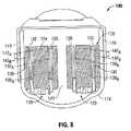
ファスナー保持スロット126の各々は、複数の手術ファスナー(例えば、手術ファスナーおよびプッシャ129(図8))のうちの1つを受容し、その結果、手術ファスナー適用処置の間に、手術ファスナーが、組織に形成される切断線の両側で、列(例えば、図1に示されている実施形態における内側および外側の列)に配置されるように構成されている。 Each of the
ファスナーカートリッジ100のさらなる詳細は、米国特許第7,070,083号を参照することで得られ、この米国特許の全体の内容は、参照により本明細書中に援用される。 Further details of the
また、ここで図2および図3を参照すると、手術ファスナーカートリッジ100は、1つ以上の種類のファスナーが装填され、そのうちの1つは、手術ファスナー130であり得る。手術ファスナー130は、2つのレグ132(その間のバックスパン134から延びている)を含む。バックスパン134およびレグ132の厚さは、手術ファスナー130が、任意の厚さの隣接する組織セグメント「T1」および「T2」を綴じるように、用いられ得る。2 and 3, the
レグ132およびバックスパン134は、長方形、楕円、四角形、三角形、台形等を含むがそれらには限定されない、任意の適切な幾何学的構成を有する断面を画定し得る。レグ132およびバックスパン134は、図2、3に示されているように手術ファスナー130の断面構成が実質的に均一であるように同じ幾何学的構成を示す。または、レグ132およびバックスパン134は、異なる構成を示す。例えば、レグ132は、長方形の断面構成を示し得、バックスパン134は、楕円の断面構成を示し得る。
手術ファスナー130の形成前に、レグ132は、実質的に平行であるように、バックスパン134から延びている。あるいは、レグ132は、バックスパンと鋭角または鈍角をなすように、バックスパンから収束または発散され得る。レグ132の各々は、貫通端136において終端し、貫通端部136は、組織(例えば、組織セグメント「T1」、「T2」(図3))を貫通するように構成されている。レグ132の貫通端部136は、組織セグメント「T1」、「T2」を貫通することを容易にするように、テーパ状であったり、あるいは、貫通端部は、テーパを含まなかったりし得る。同時係属中の米国出願第11/444,761号(2003年4月13日出願)(当該米国出願の全体の内容は、参照により本明細書中に援用される)に記載されているように、手術ファスナー130の様々な実施形態において、貫通端部136は、代替的に円錐状または平坦表面のいずれかを画定し得るようにも構想される。共有に係る米国出願第7,398,907号(当該米国出願の全体の内容は、参照により本明細書に援用される)に記載されているように、手術ファスナー130はまた、ある方向にバイアスされたステープルとして構成され得る。Prior to the formation of the
図2、3に示されている手術ファスナー130の実施形態において、バックスパン134は、実質的に直線状の構成である。組織内に形成されるとき、例えば、組織セグメント「T1」、「T2」(図3)内に形成されるときに、手術ファスナー130のレグ132は、バックスパン134と協働し、隣接する組織セグメント「T1」、「T2」を近づけて維持し、そこに圧迫力「F」を適用する。圧迫力「F」は、組織セグメント「T1」、「T2」に対して圧力を適用し、それにより、手術ファスナー130を包囲する組織を介する血流を制限し、止血を容易にする。バックスパン134の直線状の構成は、組織セグメント「T1」、「T2」に適用され得る圧力の量を制限するが、組織を介する血流の量は完全には制限されない。形成されるときに、手術ファスナー130は、実質的に「B」形状の構成を形成し、バックスパン134から形成されたレグ132の最も外側の曲線まで測定される全高さ「HF」を画定する。In the embodiment of the
図4〜7は、概して参照文字130A(図4、5)および130B(図6、7)によって識別され得る、図2に示される手術ファスナー130の代替的な構成を示している。手術ファスナー130Aは、1つ以上の突出部138Aを画定する非直線状の捩れたバックスパン134Aを含み、手術ファスナー130Bは、1つ以上の突出部138Bを画定する非直線状の捩れたバックスパン134Bを含み、その結果、バックスパン134A、134Bは、実質的に非直線状の構成になる。以下により詳細に記載されるように、手術ファスナーのバックスパン134A、134Bは、それらが異なる高さを有しているという点において、異なる構成である。形成されたとき、手術ファスナー130の実質的に直線状のバックスパン134(図2)と比較したときに、捩れたバックスパン134A、134Bの実質的に非直線状の構成は、形成の際に、手術ファスナー134A、134Bを包囲する組織を介した血流をさらに制限する。4-7 illustrate alternative configurations of the
ここで特に図4、5を参照すると、手術ファスナー130Aのバックスパン134Aは、その捩れた構成によって画定された、2つの突出物138Aを含む。バックスパンは、2つの突出物138Aを画定する捩れを有するが、さらなる突出物138Aを画定するために、さらなる捩れが提供され得るということもまた、構想される。突出物138Aは、レグ132Aの貫通端部136Aに向けてバックスパン134Aから外側に延びており、突出物138Aの上部からバックスパン134Aの最も外側の曲線まで測定される第1の高さ「H1」を画定する。手術ファスナー130Aが組織セグメント「T1」、「T2」に形成されるときに、突出物138Aは、手術ファスナー130Aのレグ132Aと協働し、組織セグメントに圧迫力「FA」を適用する。手術ファスナー130の形成の際に組織セグメント「T1」、「T2」によって占有される圧迫空間140(図3)と比較したときに、手術ファスナー130Aにおいて、バックスパン134Aとレグ132Aとの間に画定され、組織セグメント「T1」、「T2」によって占有される圧迫空間140Aは小さいので、手術ファスナー130Aによって適用される圧迫力「FA」は、手術ファスナー130によって適用される圧迫力「F」(図3)よりも大きい。したがって、手術ファスナー130と比較したときに、手術ファスナー130Aは、より大きな圧力を組織セグメント「T1」、「T2」に適用する。その結果、形成の際に手術ファスナー130Aを包囲する組織を介する血流は、形成の際に手術ファスナー130を包囲する組織を介する血流と比較したときに、より制限され得、その結果、さらなる止血を容易にする。突出物138Aおよび組織セグメント「T1」、「T2」によって占有される圧迫空間140Aの寸法は、血流が完全には制限されないが、それによって組織のどのような不必要な壊死をも防ぐようなものである。形成されるときに、手術ファスナー130Aは、手術ファスナー130によって画定される全高さ(図3)に実質的に等しい、全高さ「HF」(バックスパン134Aから形成されたレグ132Aの最も外側の曲線まで測定される)を画定する。Referring now particularly to FIG. 4 and 5, the
ここで図6、7を参照すると、手術ファスナー130Bのバックスパン134Bは、捩れた構成によって画定された2つの突出物138Bを含む。バックスパン134Bは、2つの突出物138Bを画定する捩れを有しているが、さらなる突出物138Bを画定するためにさらなる捩れが提供され得るということもまた構想される。突出物138Bは、バックスパン134Bからレグ132Bの貫通端部136Bに向けて外側に延びており、図4、5に示されている手術ファスナー130Aのバックスパン134Aから外側に向けて延びている突出物134Aの高さ「H1」よりも高い第2の高さ「H2」を画定する。したがって、手術ファスナー130Bが組織セグメント「T1」、「T2」(図7)内に形成されるとき、手術ファスナー130Bの形成の際に組織セグメント「T1」、「T2」によって占有される圧縮空間140B(図7)は、手術ファスナー130、130Aの形成の際に組織セグメント「T1」、「T2」によってそれぞれ占有される圧縮空間140(図3)および140A(図5)よりも小さいので、突出物138Bは、手術ファスナー130Bのレグ132Bと協働し、圧迫力「F」(図3)、「FA」(図5)(それぞれ、手術ファスナー130、130Aによって適用される)よりも大きな圧迫力「FB」を、組織セグメントに適用する。したがって、手術ファスナー130、130Aと比較して、手術ファスナー130Bは、より大きな圧力を組織セグメント「T1」、「T2」に適用する。その結果、形成の際に手術ファスナー130Bを包囲する組織を介する血流は、形成の際に手術ファスナー130、130Aを囲む組織を介する血流と比較したときに、より制限され得る。突出物138Bおよび組織セグメント「T1」、「T2」によって占有される圧迫空間140Bの寸法は、血流が完全にではないがかなり制限され、それにより、止血をさらに容易にし、止血を行うようなものである。形成されるときに、手術ファスナー130Bは、手術ファスナー130(図3)、130A(図5)によって画定される全高さに実質的に等しい、全高さ「HF」を画定する。6 and 7, the
図4〜図7に示されている手術ファスナー130A、130Bは、実質的に類似しているが、それぞれのバックスパン134A、134Bに形成されている1つ以上の突出物138A、138Bの寸法が異なる。それぞれの手術ファスナー130A、130Bが形成されるときに、突出物138A、138Bのそれぞれの高さ「H1」、「H2」、ならびに、組織セグメント「T1」、「T2」によって占有される圧迫空間140A、140Bの寸法は、異なる実施形態においては変化または変動し得、組織の属性(例えば、組織の厚さまたは瘢痕組織の存在)に応じて、任意の所望のレベルの止血および組織セグメント「T1」、「T2」における血流をもたらす。4-7 surgical fasteners130 A, 130 shown inB is substantially although similar, one or
図8〜図10は、図1に示されるカートリッジ本体112内に装填される手術ファスナー130、130Aを示す。手術ファスナー130、130Aは、カートリッジ本体112内に配置され、一対の第1の(内側の)列142Aと、一対の第2の(外側の)列142Bとを画定し、これらは、上壁120(図1)に形成されるファスナー保持スロット126の内側の列128Aおよび外側の列128Bに対応する。したがって、一対の内側の列142Aは、ナイフスロット122からその両側において横方向に間隔が空けられており、一対の外側の列142Bは、ナイフスロット122の両側において一対の内側の列142Aから横方向に間隔が空けられている(カートリッジの中央の長手軸からさらに遠くに)。したがって、手術ファスナー130、130Aは、綴じる際に、組織に形成される切断線(図示されず)の両側に配置される。すなわち、突出物138Aと形成されたレグ132の曲線との間の距離はより短いので、上述の突出物138A(図4、5)を含む手術ファスナー130Aは、より大きな圧迫力を組織に提供し、切断線により近い内側の列142Aに提供される。形成の際にレグ132の曲線とバックスパン134との間のより大きな距離を画定するファスナー130は、外側の列142Bに提供され、外側の列においては、手術ファスナー適用装置1000(図1)のジョーをクランプした結果として組織はより厚くなり得る。8 to 10 show a
切断線に近い組織のより大きな圧迫を提供するファスナー(すなわち、図8〜10に示されている手術ファスナーカートリッジ100の実施形態における手術ファスナー130A)を配置することにより、単一のカートリッジによって、より大きな範囲の組織の厚さが効率的にシールされ得る。しかしながら、本開示はまた、本開示の範囲から逸れることなしに、その他の方法で手術ファスナーが配置され得ることを構想していることもまた理解されるべきである。また、内側の列142Aおよび外側の列142Bは、それぞれ手術ファスナー130A、130を含むものとして示されているが、本開示は、本明細書中に開示されている手術ファスナー130(図2、3)、130A(図4、5)、130B(図6、7)のうちの任意のものの、排他的使用(単一のタイプの手術ファスナー(例えば、手術ファスナー130)のみが特定の列に存在する)、または、組み合わせ的使用(様々な手術ファスナー(例えば、手術ファスナー130、130Aが列に存在する)を構想している。By placing a fastener that provides greater compression of tissue near the cutting line (ie,
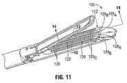
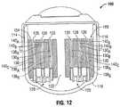
図11〜14に見ることができるように、一実施形態において、開示された手術ファスナーカートリッジ100は、ナイフスロット122から横方向外側に間隔が空けられている一対の第1の(内側の)列128A、一対の内側の列128Aから横方向外側に間隔が空けられている一対の第2の(中間の)列128B、および一対の中間の列128Bから横方向外側に間隔が空けられている一対の第3の(外側の)列128Cに配置されている、複数のファスナー保持スロット126を有する上壁120を含み、これらの列の各々は、ナイフスロット122の両側において間隔が空けられている。この実施形態において、ファスナー、例えば手術ファスナー130(図2、3)、130A(図4、5)、130B(図6、7)のそれぞれは、カートリッジ本体112内に配置され、一対の第1の(内側の)列142A、一対の第2の(中間の)列142B、一対の第3の(外側の)列142Cを画定し、これらはそれぞれ、手術ファスナーカートリッジ100の上壁120に形成されたファスナー保持スロット126の内側の列128A、中間の列128B、外側の列128Cに対応する。図1および図8〜10に示されている手術ファスナーカートリッジ100の実施形態と同様に、内側の列142A、中間の列142B、外側の列142Cのそれぞれは、本明細書中に開示されている手術ファスナー130、130A、130Bのうちの任意のものを、排他的(単一の手術ファスナー、例えば、手術ファスナー130のみが、特定の列に存在する)に含み得るか、または組み合わせで(様々な手術ファスナー、例えば、手術ファスナー130、130A、130Bが列に存在する)含み得る。As can be seen in FIGS. 11-14, in one embodiment, the disclosed
図12〜14に示されているように、1つの特定の実施形態において、外側の列142C、中間の列142B、内側の列142Aは、それぞれ手術ファスナー130、130A、130Bだけを含んでおり、その結果、切断線を直接包囲する組織を介する血流は、手術ファスナー130Bの内側の列142Aによってより多く制限され、その一方で、中間の列142Bおよび外側の列142Cのそれぞれを包囲する組織を介する血流は、手術ファスナー130A、130によってより少なく制限される。したがって、血流は、切断線に直接隣接する組織を介する場合最小化され得、切断線からの横方向の距離に伴って、だんだんと増加し得る。また、この配置によると、最大の突出物を有する手術ファスナー(例えば、手術ファスナー130B)は、切断線の最も近くに配置され得(一般に、組織がより多く圧迫される)、より少ない圧迫を提供する手術ファスナー(例えば、実質的に直線状のバックスパン134を有する手術ファスナー130)は、切断線からより遠くに配置され得る(一般に、組織がより少なく圧迫される)。直線状のバックスパンを有するファスナー130の列の代わりに、他の捩じられたバックスパンファスナーよりも小さな高さを有する、捩れたバックスパンを有するファスナーの列が、外側の列に利用され得ることも構想される。As shown in FIGS. 12-14, in one particular embodiment, outer row 142C , middle row 142B , and inner row 142A are only
ここで図1、15、16を参照して、手術ファスナー適用装置1000が議論される。手術ファスナー適用装置1000は、再利用可能または使い捨てのいずれかであり得、可動ハンドル1003Aおよび静止ハンドル1003Bを有するハンドルアセンブリ1002を含んでおり、このハンドルアセンブリは、遠位に延びている細長い軸または内視鏡部分1006を介してツールアセンブリ1004に動作可能なように連結されている。様々な実施形態において、ハンドルアセンブリ1002は、手動動作され得、追加的にまたは代替的に、モータ式、水圧式、ラチェット式等の機構を含み得る。一般に、ツールアセンブリ1004は、互いをクランプしたり、綴じたり、切断線に沿って隣接する組織セグメントを切断するように適合される。With reference now to FIGS. 1, 15, and 16, a surgical
ツールアセンブリ1004は、第1のジョー1010に対して旋回可能なように連結された第2のジョー1008を含み、その接近を容易にする。ツールアセンブリ1004の第2のジョー1008は、アンビル1100を含み、第1のジョー1010は、上述の手術ファスナーカートリッジ100(図1)を組み込む手術ファスナーカートリッジアセンブリ1200を含み、この手術ファスナーカートリッジには、複数の手術ファスナー、例えば手術ファスナー130(図2、3)、手術ファスナー130A(図4、5)、および/または手術ファスナー130B(図6、7)、(図2、3)が、装填されている。静止ハンドル1003Bに向けて可動ハンドル1003Aを旋回させることは(図1)、第2のジョー1008と第1のジョー1010とを接近させる。ジョー1008、1010が閉じてその間で組織をクランプするように整列動作した後、可動ハンドル1003Aの継続的な旋回は、手術ファスナーカートリッジ100から複数の手術ファスナー100(図3)を射出させ、その結果、手術ファスナー130、130A、130Bが、アンビル1100の中に駆動され、それにより、形成される手術ファスナーへと形成される。ツールアセンブリ1004および/または手術ファスナーカートリッジアセンブリ1200は、手術ファスナー適用装置1000のための、除去可能および置換可能な装填ユニットを含み得る。Tool assembly 1004 includes a second jaw 1008 that is pivotally connected to first jaw 1010 to facilitate its access. The second jaw 1008 of the tool assembly 1004 includes an
上述のように、手術ファスナー適用装置1000は、ナイフ部材123を含む。現在の譲受人がTyco Healthcare Group LPである同一出願人の米国特許第7,398,908号(その全体の内容は、参照により本明細書中に援用される)に記載されているように、図16に見られるようにナイフ部材123は、駆動梁1012に動作可能なように連結されている。ナイフ部材123は、アンビル部材1100と第1のジョー1010によって画定された空洞1202との両方と同時に係合するように構成され得、寸法が決められ得る。 As described above, the surgical
使用中、ツールアセンブリ1004(図15)は、最初に、可動ハンドル1003Aを操作することによって組織をクランプし、制御ロッド(図示されず)を遠位に前進させるように作動される。制御ロッドの遠位の前進の結果、ナイフ部材123(図16)の対応する前進が起こり、アンビル部材1100と手術ファスナーカートリッジアセンブリ1200との接近をもたらす。アンビル部材1100と手術ファスナーカートリッジアセンブリ1200との間で組織がクランプされると、ファスナー、例えば、手術ファスナー130(図2、3)、手術ファスナー130A(図4、5)、および/または手術ファスナー130B(図6、7)は、手術ファスナー適用装置1000(図1)から組織の中に発射される。その後、可動ハンドル1003Aは、再びナイフ部材123(図16)をさらに前進させるように動作する。In use, the tool assembly 1004 (FIG. 15) is initially actuated to clamp tissue by manipulating the movable handle 1003A and advance a control rod (not shown) distally. As a result of the distal advancement of the control rod, a corresponding advancement of the knife member 123 (FIG. 16) occurs, resulting in the access between the
ここで図1〜16を参照して、ファスナー適用装置1000(図1)を用いて組織を閉じる方法が記載される。使用中、手術ファスナー適用装置1000は、現在の譲受人がTyco Healthcare Group LPである、同一出願人の米国特許第5,865,361号(その全体の内容は、参照により本明細書中に援用される)に開示されているようなその他の公知の手術ファスナー適用装置と同様に、そしてその他の公知の手術ファスナー適用装置にしたがって、接近および発射される。 With reference now to FIGS. 1-16, a method of closing tissue using a fastener applying apparatus 1000 (FIG. 1) will be described. In use, surgical
可動ハンドル1003A(図15)は、作動軸に動作可能なように連結されており、この作動軸は、可動ハンドル1003Aの操作が作動軸の直線的な前進をもたらし、それが制御ロッドの対応する直線的な前進を引き起こすように、制御ロッドの近位端を受容する。制御ロッドと係合可能な軸方向駆動アセンブリもまた提供される。より詳細には、軸方向駆動アセンブリは、ナイフ部材123を支持する遠位端を含む細長い駆動梁1012(図16)と、制御ロッドと契合するように構成され寸法が決められた駆動部材とを含む。図16に示されているように、ナイフ部材123は、スレッド(sled)1204の背後で平行移動するように配置されている。Movable handle 1003A (FIG. 15) is operably connected to an actuation shaft that operates upon movement of movable handle 1003A resulting in a linear advance of the actuation shaft. Receiving the proximal end of the control rod to cause a corresponding linear advance. An axial drive assembly engageable with the control rod is also provided. More particularly, the axial drive assembly includes an elongated drive beam 1012 (FIG. 16) that includes a distal end that supports a
手術ファスナー適用装置1000(図15)が、ツールアセンブリ1004の開いたジョー1008、1010の間で標的組織を配置するように操作された後に、ジョー1008、1010は、ハンドルアセンブリ1002を用いて、その間に標的組織をクランプして、標的組織に圧迫力を加えるように接近させられる。詳細には、可動ハンドル1003Aの操作は、作動軸を前進させ、制御ロッドの対応する前進をもたらす。制御ロッドは、その遠位端において、上述の駆動梁1012(図16)を含む駆動アセンブリに連結されているので、制御ロッドの遠位の動きは、駆動梁1012の対応する動きを引き起こし、その結果、アンビル1100を手術ファスナーカートリッジアセンブリ1200に向けて強制する。After the surgical fastener applying device 1000 (FIG. 15) has been manipulated to place the target tissue between the open jaws 1008, 1010 of the tool assembly 1004, the jaws 1008, 1010 can be The target tissue is clamped and brought into close proximity to apply a compression force to the target tissue. Specifically, operation of the movable handle 1003A advances the actuation axis, resulting in a corresponding advance of the control rod. Because the control rod is coupled at its distal end to a drive assembly that includes the
組織がジョー1008、1010(図1)の間でしっかりとクランプされるとき、手術ファスナー適用装置1000は、手術ファスナー、例えば手術ファスナー130(図2、3)、手術ファスナー130A(図4、5)、および/または手術ファスナー130B(図6、7)を射出するように発射される。手術ファスナー適用装置1000(図15)を発射させるために、可動ハンドル1003Aが、駆動アセンブリの前進を引き起こすように再び操作され、この前進は、スレッド1204(図16)にカートリッジ本体1202を横断させ、手術ファスナーカートリッジ100(図1)から、複数の手術ファスナー130、130A、130Bを射出させる。より詳細には、スレッド1204が遠位に動くときに、このスレッドは、プッシャ129(図8、12、16)と係合し、それにより、手術ファスナー130、130A、130Bを上方向に(すなわち、手術ファスナーカートリッジ100の上壁120(図1)に向けて)駆動させる。手術ファスナー130、130A、130Bが上方向に向けて駆動されるとき、ファスナー保持スロット126は、その相対的な位置を維持する。When the tissue is securely clamped between the jaws 1008, 1010 (FIG. 1), the surgical
ファスナー保持スロット126を通過した後に、手術ファスナー130、130A、130Bは組織を通過し、アンビル1100の組織接触表面1104に形成されたポケット1102と係合させられ、それにより、例えば、図3、5および7のそれぞれに見られる形成された構成を達成する。上述のように、組織内に形成された際、手術ファスナー130、130A、130Bは、切断線に直接隣接して包囲する組織を介する血流を制限し、それにより止血をもたらし、その一方で、切断線から横方向外側に間隔が空けられた組織を介してより多くの血流が流れることを可能にすることによって組織の壊死を最小化する。After passing through the
組織を手術吻合で綴じることを実行するために腹腔鏡処置に用いられるように適合された、手術ファスナー適用装置1000に関連して、ツールカートリッジが議論されてきたが、カートリッジは、複数の手術ファスナー(例えば、手術ファスナー130、130A、130B)を組織の断面に適用する意図された目的のために適した、任意の手術器具と共に用いるように適合され得る。Although a tool cartridge has been discussed in connection with the surgical
例えば、ツールアセンブリ1004(図1)は、例えば、現在の譲受人がTyco Healthcare Group LPである同一出願人の米国特許第7,455,676号(その内容は、参照により本明細書中に援用される)に開示されているような、端々吻合装置2000(図17)との使用に適合され得る。装置2000は、実質的に管状の列に複数の手術ファスナーを同時に配置するように用いられる。ナイフは、ファスナーの発射と共に前進させられる。装置200は、一対の作動ハンドル部材2004を有するハンドルアセンブリ2002と、手術ファスナーを含むカートリッジ2012に向けてアンビル2016を動かす(引っ込める)ための接近ノブ(蝶ナット)とを含む。カートリッジ2012は、ハンドルアセンブリ2002から延びている管状の本体部分2008の遠位端部にある。アンビル軸2014は、アンビル2016をハンドルアセンブリ2002に動作可能なように連結し、その結果、アンビル2016は、アンビルが閉じた際にファスナーカートリッジ2012と密接に協働整列した位置から、アンビルがファスナーステープルカートリッジ2012から離れている位置へと、位置変えすることが可能である。 For example, the tool assembly 1004 (FIG. 1) is, for example, commonly assigned US Pat. No. 7,455,676, whose current assignee is Tyco Healthcare Group LP, the contents of which are incorporated herein by reference. Can be adapted for use with the end-to-end anastomosis device 2000 (FIG. 17). The device 2000 is used to simultaneously place a plurality of surgical fasteners in a substantially tubular row. The knife is advanced with the firing of the fastener. The
ツールアセンブリ2010は、ファスナーカートリッジ2012内に配置されたファスナー射出部材を含む。ファスナー射出部材は、周囲に間隔を置いて配置されたステープルプッシャの同心円状リングを画定する遠位部分を含み、このステープルプッシャは、それぞれのステープル保持スロット内に受容され、ファスナーカートリッジ2012から手術ファスナーを射出する。ファスナー射出部材は、駆動チューブの遠位端によって接触されるように構成され、寸法が決められ、この駆動チューブは、本体部分2008を介してハンドル部材2004に動作可能なように連結され、その結果として操作が駆動チューブの前進をもたらし、ステープルプッシャをファスナーカートリッジ2012内に保持される複数の手術ファスナーと係合させ、組織を介したファスナーの射出を引き起こさせ、ステープルプッシャをアンビル2016のアンビルポケットと接触させ、ファスナーの構成は可変的なので、組織に可変圧迫力を提供する。
ツールアセンブリ1004(図1)はまた、例えば同一出願人の米国特許第7,334,717号(その全体の内容は、参照により本明細書中に援用される)に開示されているような、手術ステープル装置3000(図18)と共に用いるようにも適合され得る。手術ステープル装置3000は、実質的に直線状の複数の列に配置された複数の手術ファスナーを収容するカートリッジ受容半分セクション3002と、対応する列に配置された複数のアンビルポケットを含むアンビル半分セクション3004とを含む。半分セクション3002、3004は、使用中の接近のために、ハンドル3006、3008を介して、旋回可能なように連結される。 Tool assembly 1004 (FIG. 1) is also disclosed, for example, in commonly assigned US Pat. No. 7,334,717, the entire contents of which are incorporated herein by reference, It may also be adapted for use with the surgical stapling device 3000 (FIG. 18). Surgical stapling device 3000 includes a cartridge receiving
組織をその間にクランプするための半分セクション3002、3004の接近の後、手術ファスナー適用装置3000は、発射ノブ3012の前進によって発射機構3010を遠位に前進させることにより、発射される。発射機構3010の遠位の動きは、複数のカムバーを複数のプッシャと相互作用するカム作用面と係合させ、組織を介して複数の手術ファスナーをカートリッジ受容半分セクション3002から排出させ、アンビル部分3004のアンビルポケットと接触させ、ファスナーの構成が可変的であることにより、組織に可変圧迫力を提供する。手術ファスナーは、長手方向の動きの間にその動きによって切断線に沿って組織を切断するナイフをガイドするトラックの両側に配置される。 After access of
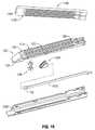
ツールアセンブリ1004(図1)はまた、共有の米国特許第5,964,394号、7,070,083号(これらの全体の内容は、参照により本明細書中に援用される)に開示されているような、横断吻合ファスナー器具4000(図19)と共に用いることに適合され得る。手術ファスナー適用装置4000は、接近レバー4001と、可動ハンドル4002と、ハンドル4002から遠位に延びている細長い部分4004とを含む。器具の長手軸と横断する実質的に直線状の列に配置された複数のファスナーを含むカートリッジ200は、フレーム4006のカートリッジ受容部分4014内で支持される。 Tool assembly 1004 (FIG. 1) is also disclosed in co-owned US Pat. Nos. 5,964,394, 7,070,083, the entire contents of which are incorporated herein by reference. Can be adapted for use with the transverse anastomosis fastener device 4000 (FIG. 19). Surgical fastener applying apparatus 4000 includes an access lever 4001, a
手術ファスナー適用装置4000の発射の前に、接近レバー4001が作動され、手術ファスナーカートリッジ200に動作可能なように連結された駆動部材を遠位に前進させ、手術ファスナーカートリッジ200を静止したままのアンビル4012に向けて動かし、その間で組織を捕捉する。その後、ハンドル4002は、細長い部分4004を介してプッシャバーを遠位に前進させるように動かされ、プッシャバーの遠位端に含まれるヘッド部分の対応する動きを引き起こす。ヘッド部分は、そこから遠位に延びている複数のフィンガーを含み、それらは、カートリッジアセンブリと係合することにより、その中に保持された複数の手術ファスナーを、組織を介して射出し、形成のためにアンビル4012のアンビルポケットと接触させるように構成され、寸法が決められ、直径が可変的であることにより、組織に可変圧迫力を提供する。ナイフは、装置内に提供され得る。 Prior to firing of surgical fastener applicator 4000, access lever 4001 is actuated to advance a drive member operably coupled to
ツールアセンブリ1006(図1)はまた、共有の米国特許第6,045,560号、5,964,394号、5,894,979号、5,878,937号、5,915,616号、5,836,503号、5,865,361号、5,862,972号、5,817,109号、5,797,538号および5,782,396号(これらの全体の内容は、参照により本明細書中に援用される)において議論されているような、その他の手術ファスナー適用装置のうちの任意のものと用いるように適合され得る。 Tool assembly 1006 (FIG. 1) is also described in commonly owned US Pat. Nos. 6,045,560, 5,964,394, 5,894,979, 5,878,937, 5,915,616, 5,836,503, 5,865,361, 5,862,972, 5,817,109, 5,797,538 and 5,782,396 (the entire contents of these are referred to) May be adapted for use with any of the other surgical fastener applying devices, such as those discussed in US Pat.
本開示のさらなる実施形態において、手術ファスナー適用装置は、手術ファスナーを配置するためにプッシャと相互作用する複数のカムバーを含み得る。例えば、米国特許第5,318,221号(その全体は参照により本明細書中に援用される)に開示されている手術ファスナー適用装置は、複数のカムバーおよびナイフを保持するバーアダプタを有する。チャネルが装置のハンドルの動作を介して前進させられ、これは、カムバーおよびナイフを前方に駆動する。アンビルの近位端を包囲するカムチューブは、アンビルとカートリッジとを共にクランプするように、前進させられる。別の実施形態において、米国特許第5,782,396号(その開示内容は、参照により本明細書中に援用される)に開示されている手術ファスナー適用装置は、作動スレッドを有する。細長い駆動梁は、装置のハンドルの動作を介して遠位に前進させられ、作動スレッドを前方に駆動する。駆動梁の遠位端は、駆動梁が遠位に移動するときに、アンビルとカートリッジを支持するチャネルとに係合し、ステープルを配置し、アンビルとカートリッジとを共にクランプする。 In further embodiments of the present disclosure, the surgical fastener applying apparatus may include a plurality of cam bars that interact with the pusher to position the surgical fastener. For example, a surgical fastener applying apparatus disclosed in US Pat. No. 5,318,221 (incorporated herein by reference in its entirety) has a bar adapter that holds a plurality of cam bars and knives. The channel is advanced through movement of the device handle, which drives the cam bar and knife forward. A cam tube surrounding the proximal end of the anvil is advanced so as to clamp the anvil and the cartridge together. In another embodiment, the surgical fastener applying apparatus disclosed in US Pat. No. 5,782,396, the disclosure of which is incorporated herein by reference, has an actuation sled. The elongate drive beam is advanced distally through movement of the device handle to drive the actuation sled forward. The distal end of the drive beam engages the anvil and the channel that supports the cartridge as the drive beam moves distally to place the staple and clamp the anvil and the cartridge together.
ここで図20を参照すると、手術ファスナーカートリッジの代替的な実施形態が、議論され、手術ファスナーカートリッジは、概して、参照文字200によって識別される。手術ファスナーカートリッジ200は、上で議論された手術ファスナーカートリッジ100と実質的に類似しており、したがって、それらの違いに関してのみ議論される。 Referring now to FIG. 20, an alternative embodiment of a surgical fastener cartridge is discussed, and the surgical fastener cartridge is generally identified by
手術ファスナーカートリッジ200は、上述の手術ファスナー100の場合と同様に、1つ以上の列に配置された複数の手術ファスナーが装填される。しかしながら、手術ファスナーカートリッジ100とは対照的に、手術ファスナーカートリッジ200は、ナイフまたはその他の切断要素の収容のためのナイフスロットを含まない。しかしながら、ナイフスロットを含む代替的な実施形態は、本開示の範囲内にあり得る。手術ファスナーカートリッジ200は、カートリッジ本体212の上壁220の上に、複数のファスナー保持スロット226を含み、これらのスロットは、複数の列228に配置される。保持スロット226の列228は、カートリッジ本体212によって画定される長手軸「A−A」に沿って伸びている中心線252から横方向外側に間隔が空けられており、側壁214、216から等距離に配置され得る。示されているように、複数の列228は、中心線252の両側に等距離に配置されている一対の第1の(内側の)列228Aと、一対の内側の列228Aから横方向外側に配置されている一対の第2の(外側の)列228Bとを含み、第2の列はカートリッジの長手軸からさらに離れており、これらもまた中心線252の両側に配置されている。ファスナー保持スロット226の各々は、複数の手術ファスナー、例えば、手術ファスナー130(図2、3)、130A(図4、5)または130B(図6、7)のうちの1つとプッシャ129(図8)とをその中に受容し、それにより、手術ファスナーが、中心線252の両側で、複数の列(例えば、図20に示されている手術ファスナーカートリッジ200の実施形態における内側および外側の列)に配置されるように、構成され、寸法が決められている。As with the
手術ファスナーカートリッジ200は、一対の第1の列228Aおよび一対の第2の列228Bのそれぞれを含むように示されているが、手術ファスナーカートリッジ100に関して上で議論されたように、手術ファスナーカートリッジ200の代替的な実施形態においては、さらなる列のファスナー保持スロット226が、そしてさらなる列の手術ファスナーが含まれ得る。また、例えば手術ファスナーカートリッジ100に関して上で議論された様々な例示的な構成のうちの任意の構成で、ファスナーが、手術ファスナーカートリッジ200内に配置され得ることが構想される。
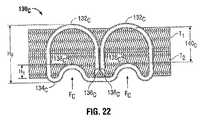
ここで図21〜24に対する参照がなされ、これらの図は、図2に示される手術ファスナー130の代替的な構成を示しており、これらの構成は、概して参照文字130C(図21、22)および130D(図23、24)によって識別され、これらの手術ファスナーは、例えば図1、8に示されている手術ファスナーカートリッジ100の中に装填され得、本明細書中に記載されている様々な装置と共に用いられる。手術ファスナー130Cは、非直線状のバックスパン134Cを含み、該バックスパン内に1つ以上の凹所138Cが形成されている。凹所138Cは、バックスパン134Cから内側へと(すなわち、形成されていない状態において、貫通端部136Cに向けて)アーチ状に延びている湾曲部分を形成し、第1の高さ「H1」を有する1つ以上のこぶを画定し、このこぶは、手術ファスナー130Cを包囲する組織を介する血流を制限するように機能する。示されているように、ファスナーの形成された状態において、バックスパンは、好適には、レグのうちの一つの曲線と対向する第1の湾曲部分と、他のファスナーレグの曲線と対向する第2の湾曲部分とを有する。Reference is now made to FIGS. 21-24, which show alternative configurations of the
例えば図22に見られるように、手術ファスナー130Cが組織セグメント「T1」、「T2」内に形成されるとき、曲線(こぶ)138Cは、手術ファスナー130Cのレグ132と協働し、圧迫力「FC」を組織セグメントに適用する。手術ファスナー130における組織セグメント「T1」、「T2」によって占有される圧迫空間140(図3)と比較したときに、手術ファスナー130Cにおいては、バックスパン134Cとレグ132Cとの間に画定され、組織セグメント「T1」、「T2」によって占有される圧迫空間140Cは小さいので、手術ファスナー130Cによって適用される圧迫力「FC」は、手術ファスナー130(図3)によって適用される圧迫力「F」よりも大きい。したがって、より大きな圧力が、手術ファスナー130Cによって、組織セグメント「T1」、「T2」に適用される。結果的に、手術ファスナー130Cを包囲する組織を介する血流は、手術ファスナー130(図3)を包囲する組織を介する血流と比較したときに、より制限され、その結果、さらなる止血を容易にする。凹所/曲線138Cと組織セグメント「T1」、「T2」によって占有される圧迫空間140Cとの寸法は、血流が完全には制限されないが、それによって組織のどのような不必要な壊死をも防ぐようなものである。形成されるときに、手術ファスナー130Cは、手術ファスナー130によって画定される全高さ(図3)と実質的に等しい、全高さ「HF」(バックスパン134Cから、形成されたレグ132Cの最も外側の湾曲まで測定される)を画定する。For example, as seen in FIG. 22, the
図23、24を特に参照すると、参照文字130Dによって概して識別されている、手術ファスナーの代替的な実施形態が、形成された状態で示されている。手術ファスナー130Dは、一対のこぶまたは曲線を画定するバックスパン134Dに形成された一対の凹所/曲線138Dを含んでいるという点で、図21および22に関連して上で議論された手術ファスナー130Cと類似している。しかしながら、手術ファスナー130Dのバックスパン134Dに形成された凹所/窪み138Dは、図21および22に示されている手術ファスナー130Cのバックスパン134Cに形成されたこぶまたは凹所138Cの高さ「H1」よりも大きい高さ「H2」を画定する。したがって、手術ファスナー130Dが、組織セグメント「T1」、「T2」内に形成されるときに、凹所/曲線138Dは、手術ファスナー130Dのレグ132Dと協働し、組織セグメントに圧迫力「FD」を適用する。手術ファスナー130、132Cにおいて組織セグメント「T1」、「T2」によってそれぞれが占有される圧迫空間140(図3)、140C(図22)と比較したときに、手術ファスナー130Dにおいては、組織セグメント「T1」、「T2」によって占有される圧迫空間140Dは小さいので、手術ファスナー130Dによって適用される圧迫力「FD」は、手術ファスナー130(図2、3)、130C(図21、22)のそれぞれによって適用される圧迫力「F」、「FC」よりも大きい。したがって、より大きな圧力が、手術ファスナー130Dによって、組織セグメント「T1」、「T2」に適用される。結果的に、手術ファスナー130Dを包囲する組織を介する血流は、手術ファスナー130(図3)、130C(図21、22)を包囲する組織を介する血流と比較したときに、より制限される。凹所/曲線138Dと組織セグメント「T1」、「T2」によって占有される圧迫空間140Dとの寸法は、血流が完全には制限されないが、かなり制限され、それによって止血をさらに容易にしたり、止血をもたらしたりするような寸法である。形成されるとき、手術ファスナー130Dは、手術ファスナー130(図3)、130C(図22)によって画定される全高さ(図3)と実質的に等しい、全高さ「HF」を画定する。With particular reference to FIG. 23 and 24,
手術ファスナー130C(図21、22)、130D(図23、24)は、実質的に類似した構成であるが、バックスパン134C、134Dに形成された凹所138C、138Dによって形成される(少なくとも1つの)こぶ(曲線)の寸法が異なる。それぞれの手術ファスナー130C、130Dが形成された状態のときに、凹所/曲線138C、138Dのそれぞれの高さ「H1」、「H2」、ならびに、組織セグメント「T1」、「T2」によって占有される圧迫空間140C、140Dの寸法は、異なる実施形態においては変化または変動し得、組織の属性(例えば、組織の厚さまたは瘢痕組織の存在)に応じて、任意の所望のレベルの止血および組織セグメント「T1」、「T2」における血流をもたらす。Surgical fasteners 130C (FIGS. 21, 22), 130D (FIGS. 23, 24) are substantially similar in construction, but with
図25および図26は、図1に見られるカートリッジ本体100内に装填される手術ファスナー130(図3)および130C(図21、22)を示している。手術ファスナー130C、130は、カートリッジ本体112内に配置され、上壁120(図1)に形成されたファスナー保持スロット126の内側の列128Aおよび外側の列128Bのそれぞれに対応する、一対の第1の(内側の)列142Aと、一対の第2の(外側の)列142Bとを画定する。したがって、一対の内側の列142Aは、ナイフスロット122の両側で、ナイフスロット122から横方向外側に間隔が空けられており、一対の外側の列142Bは、ナイフスロット122の両側で、一対の内側の列142Aから横方向外側に間隔が空けられており、かつ、カートリッジの中央の長手軸からさらに離れている。したがって、手術ファスナー130、130Cは、綴じる際に、組織に形成される切断線(図示されず)の両側に配置され得る。すなわち、上述の突出物または曲線138C(図20、21)を含む手術ファスナー130Cは、突出物138Cと形成されたレグ132の曲線との間の距離はより短いので、より大きな圧迫力を組織に提供し、したがって、切断線により近い内側の列142Aに提供される。形成の際にレグ132の曲線とバックスパン134との間のより大きな距離を画定するファスナー130は、外側の列142Bに提供され、外側の列においては、装置(例えば、手術ファスナー適用装置1000(図1))のジョーをクランプした結果として、組織はより厚くなり得る。25 and 26 show surgical fasteners 130 (FIG. 3) and 130C (FIGS. 21 and 22) loaded into the
切断線に近い組織のより大きな圧迫を提供するファスナー(すなわち、図24および図25に示されている手術ファスナーカートリッジ100の実施形態における手術ファスナー130C)を配置することにより、単一の手術ファスナーカートリッジによって、より大きな範囲の組織の厚さが効率的にシールされ得る。しかしながら、本開示はまた、本開示の範囲から逸脱することなしに、その他の方法で手術ファスナーが配置され得ることを構想していることもまた理解されるべきである。また、内側の列142Aおよび外側の列142Bは、それぞれ手術ファスナー130C、130を含むものとして示されているが、本開示は、本明細書中に上で開示されている手術ファスナー130(図2、3)、130A(図4、5)、130B(図6、7)、130C(図20、21)、130C(図22、23)のうちの任意のものの、排他的使用(単一のタイプの手術ファスナー、例えば、手術ファスナー130のみが特定の列に存在する)、または、組み合わせ的使用(様々な手術ファスナー、例えば、手術ファスナー130および130Cが存在する)を構想している。By placing a fastener (ie,
図27および図28は、図1に示されているカートリッジ本体112に手術ファスナー130(図3)、130C(図21、22)、130D(図23、24)が装填され得る、本開示の別の実施形態を示している。この実施形態においては、図1および図11〜14に見られ、上述された実施形態と同様に、開示されている手術ファスナーカートリッジ100は、複数のファスナー保持スロット126を有する上壁120を含み、複数のファスナー保持スロットは、ナイフスロット122から横方向に間隔が空けられている、一対の第1の(内側の)列と、内側の列から横方向に間隔が空けられている、一対の第2の(中間の)列と、一対の中間の列から横方向外側に間隔が空けられている、一対の第3の(外側の)列とに配置され、これらの各々は、ナイフスロット122の両側で間隔を空けて配置されている。したがって、ファスナー(例えば、手術ファスナー130、130C、130D)は、カートリッジ本体112内に配置され、一対の第1の(内側の)列142Aと、一対の第2の(中間の)列142Bと、一対の第3の(外側の)列142Cとを画定し、これらはそれぞれ、手術ファスナーカートリッジ100の上壁120に形成されたファスナー保持スロット126の内側の列128A、中間の列128B、外側の列128Cに対応している。この実施形態においては、図1および図11〜14の実施形態と同様に、内側の列142A、中間の列142B、外側の列142Cの各々は、本明細書中に開示されている手術ファスナー130、130C、130Dのうちの任意のものを、排他的(単一のタイプの手術ファスナー、例えば、手術ファスナー130のみが特定の列に存在する)に含み得るか、または組み合わせで(様々な手術ファスナー、例えば、手術ファスナー130、130C、130Dが存在する)含み得る。しかしながら、図27および図28に示されている特定の実施形態においては、外側の列142C、中間の列142B、内側の列142Aは、それぞれ手術ファスナー130、130C、130Dだけを含んでおり、その結果、切断線を直接包囲する組織を介する血流は、手術ファスナー130Dの内側の列142Aによってより多く制限され、その一方で、中間の列142Bおよび外側の列142Cのそれぞれを包囲する組織を介する血流は、それぞれ手術ファスナー130C、130によってより少なく制限される。したがって、血流は、切断線に直接隣接する組織を介して最小化され得、切断線からの横方向の距離に伴って、だんだんと増加し得る。また、この配置によると、最大の湾曲部分/凹所を有する手術ファスナー(例えば、手術ファスナー130D)は、切断線の最も近くに配置され得(一般に、組織がより多く圧迫される)、より少ない圧迫を提供する手術ファスナー(例えば、実質的に直線状のバックスパン134を含む手術ファスナー130)は、上述のように、切断線からより遠くに配置され得る(一般に、組織がより少なく圧迫される)。FIGS. 27 and 28 illustrate the present disclosure in which the
上記の記載、開示、および図面は、限定として見なされるべきではなく、特定の実施形態の単なる例示として見なされるべきである。したがって、本開示は、記載されているそのままの実施形態に限定されず、当業者により、様々なその他の変更および改変が、本開示の範囲および精神から逸脱することなしに、なされ得ることが理解されるべきである。したがって、当業者は、一実施形態に関連して図示または記載されている要素および特徴が互いに組み合わされ得ること、および、改変および変形もまた、本開示の範囲内に含まれるということを理解し得る。 The above description, disclosure, and drawings should not be construed as limiting, but merely as exemplifications of particular embodiments. Accordingly, the present disclosure is not limited to the exact embodiments described, and it is understood that various other changes and modifications can be made by those skilled in the art without departing from the scope and spirit of the present disclosure. It should be. Accordingly, those skilled in the art will appreciate that the elements and features illustrated or described in connection with one embodiment can be combined with each other, and that modifications and variations are also included within the scope of this disclosure. obtain.
100 手術ファスナーカートリッジ
114、116 側壁
118 底壁
120 上壁
122 ナイフスロット
123 ナイフ部材
126 ファスナースロット
128 列100
Claims (8)
Translated fromJapanese該第1のジョーには、複数の手術ファスナーが配置されたカートリッジ本体を含み、
該複数の手術ファスナーは、第1の構成の第1のバックスパンを有する複数の第1の手術ファスナーと、第2の構成の第2のバックスパンを有する複数の第2の手術ファスナーとを含み、
該第1の構成は、該第2の構成とは異なり、該複数の第1の手術ファスナーは、形成の際に第1の圧迫力を組織に適用し、
該複数の第2の手術ファスナーは、形成の際に第2の異なる圧迫力を組織に適用し、
該複数の第1の手術ファスナーは、第1の列に配置され、
該複数の第2の手術ファスナーは、該第1の列から横方向外側に第2の列に配置され、
該第1および第2の手術ファスナーの該第1および第2のバックスパンは、該第1の圧迫力が該第2の圧迫力よりも大きくなるように、構成され、寸法が決められており、
該複数の第1の手術ファスナーの該バックスパンは、該第1のバックスパンの長さ方向の周りを該第1のバックスパンの長さ方向に沿って回転されることにより、第1の高さを画定する捩れた構成を形成し、
該複数の第2の手術ファスナーの該バックスパンは、実質的に直線状の構成を有するか、または、該第2のバックスパンの長さ方向の周りを該第2のバックスパンの長さ方向に沿って回転されることにより、第2の高さを画定する捩れた構成を形成し、
該第1の高さは、該第2の高さよりも高い、手術ファスナー適用装置。A surgical fastener applying apparatus including first and second jaws,
The first jaw includes a cartridge body in which a plurality of surgical fasteners are disposed,
The plurality of surgical fasteners includes a plurality of first surgical fasteners having a first backspan having a first configuration and a plurality of second surgical fasteners having a second backspan having a second configuration. ,
The first configuration differs from the second configuration in that the plurality of first surgical fasteners apply a first compression force to the tissue during formation;
The plurality of second surgical fasteners apply a second different compression force to the tissue during formation;
The plurality of first surgical fasteners are arranged in a first row;
The plurality of second surgical fasteners are disposed in a second row laterally outward from the first row;
The first and second backspans of the first and second surgical fasteners are configured and dimensioned such that the first compression force is greater than the second compression force. ,
The backspan of the plurality of first surgical fasteners is rotated about the length of the first backspan along the length of the first backspan, thereby providing a first height Forming a twisted configuration defining the thickness,
The backspan of the plurality of second surgical fasteners has a substantially linear configuration, or the lengthwise direction of the second backspan about the length of the second backspan To form a twisted configuration that defines a second height,
The surgical fastener applying apparatus, wherein the first height is higher than the second height .
該第3のファスナーは、前記第1および第2のバックスパンの前記第1および第2の構成のそれぞれとは異なる第3の構成を有する第3のバックスパンを有し、
該第3のファスナーは、形成の際に第3の圧迫力を組織に適用し、
該第3の圧迫力は、前記第1の圧迫力よりも小さく、前記第2の圧迫力よりも小さい、請求項1に記載の手術ファスナー適用装置。A plurality of third fasteners arranged in a third row laterally outside the plurality of second surgical fasteners arranged in a second row;
The third fastener has a third backspan having a third configuration different from each of the first and second configurations of the first and second backspans;
The third fastener applies a third compression force to the tissue during formation,
The surgical fastener applying apparatus according to claim1 , wherein the third compression force is smaller than the first compression force and smaller than the second compression force.
レグの間の該バックスパンのうちの少なくとも2つの部分は、該レグ貫通端に向けて延びている、請求項1〜2のいずれか一項に記載の手術ファスナー適用装置。The backspan includes a plurality of twists;
The surgical fastener applying apparatus according to any one of claims 1 to2 , wherein at least two portions of the backspan between the legs extend toward the leg penetrating ends.
該第1のバックスパンは、該貫通端に向けて延びており第1の高さを画定するように寸法が決められている少なくとも1つの第1の曲線を含み、あるいは、
該第1の手術ファスナーと前記第2の手術ファスナーとの両方は、前記第2のバックスパンから延びており貫通端で終端しているレグを含み、
該第2のバックスパンは、該貫通端に向けて延びており該第1の高さよりも小さい第2の高さを画定するように寸法が決められている少なくとも1つの曲線を含む、請求項1に記載の手術ファスナー適用装置。The first surgical fastener includes a leg extending from the first backspan and terminating at a penetrating end;
The first backspan includes at least one first curve extending toward the penetrating end and dimensioned to define a first height; or
Both the first surgical fastener and the second surgical fastener include a leg extending from the second backspan and terminating at a penetrating end;
The second backspan includes at least one curve extending toward the penetrating end and dimensioned to define a second height that is less than the first height. surgical fastener applying apparatus according to1.
前記第1および第2のジョーは、旋回可能なように取り付けられているか、または、該第1および第2のジョーのうちの少なくとも1つは、該ジョーの間で組織をクランプするために、実質的に直線状の方向に動くことができ、該ジョーを接近位置に動かす、請求項1〜7のいずれか一項に記載の手術ファスナー適用装置。The first and second rows are substantially linear or substantially annular;
It said first and second jawsare either mounted so as to be pivotable, or at least one of first and second jawsto clamp the tissue between the said jaws, The surgical fastener applying apparatus according to any one of claims 1 to7 , wherein the surgical fastener applying apparatus is movable in a substantially linear direction and moves the jaw to an approach position.
Applications Claiming Priority (6)
| Application Number | Priority Date | Filing Date | Title |
|---|---|---|---|
| US4469608P | 2008-04-14 | 2008-04-14 | |
| US4465608P | 2008-04-14 | 2008-04-14 | |
| US61/044,696 | 2008-04-14 | ||
| US61/044,656 | 2008-04-14 | ||
| US12/417,685 | 2009-04-03 | ||
| US12/417,685US7926691B2 (en) | 2008-04-14 | 2009-04-03 | Variable compression surgical fastener cartridge |
Publications (2)
| Publication Number | Publication Date |
|---|---|
| JP2009254825A JP2009254825A (en) | 2009-11-05 |
| JP5455417B2true JP5455417B2 (en) | 2014-03-26 |
Family
ID=40908780
Family Applications (1)
| Application Number | Title | Priority Date | Filing Date |
|---|---|---|---|
| JP2009097516AExpired - Fee RelatedJP5455417B2 (en) | 2008-04-14 | 2009-04-13 | Variable compression surgical fastener cartridge |
Country Status (6)
| Country | Link |
|---|---|
| US (5) | US7926691B2 (en) |
| EP (2) | EP3130292B1 (en) |
| JP (1) | JP5455417B2 (en) |
| AU (1) | AU2009201410A1 (en) |
| CA (1) | CA2673187C (en) |
| ES (1) | ES2587389T3 (en) |
Families Citing this family (803)
| Publication number | Priority date | Publication date | Assignee | Title |
|---|---|---|---|---|
| US5865361A (en) | 1997-09-23 | 1999-02-02 | United States Surgical Corporation | Surgical stapling apparatus |
| US20070084897A1 (en) | 2003-05-20 | 2007-04-19 | Shelton Frederick E Iv | Articulating surgical stapling instrument incorporating a two-piece e-beam firing mechanism |
| US9060770B2 (en) | 2003-05-20 | 2015-06-23 | Ethicon Endo-Surgery, Inc. | Robotically-driven surgical instrument with E-beam driver |
| US8905977B2 (en) | 2004-07-28 | 2014-12-09 | Ethicon Endo-Surgery, Inc. | Surgical stapling instrument having an electroactive polymer actuated medical substance dispenser |
| US9072535B2 (en) | 2011-05-27 | 2015-07-07 | Ethicon Endo-Surgery, Inc. | Surgical stapling instruments with rotatable staple deployment arrangements |
| US11998198B2 (en) | 2004-07-28 | 2024-06-04 | Cilag Gmbh International | Surgical stapling instrument incorporating a two-piece E-beam firing mechanism |
| US11890012B2 (en) | 2004-07-28 | 2024-02-06 | Cilag Gmbh International | Staple cartridge comprising cartridge body and attached support |
| US8215531B2 (en) | 2004-07-28 | 2012-07-10 | Ethicon Endo-Surgery, Inc. | Surgical stapling instrument having a medical substance dispenser |
| US10159482B2 (en) | 2005-08-31 | 2018-12-25 | Ethicon Llc | Fastener cartridge assembly comprising a fixed anvil and different staple heights |
| US7673781B2 (en) | 2005-08-31 | 2010-03-09 | Ethicon Endo-Surgery, Inc. | Surgical stapling device with staple driver that supports multiple wire diameter staples |
| US11484312B2 (en) | 2005-08-31 | 2022-11-01 | Cilag Gmbh International | Staple cartridge comprising a staple driver arrangement |
| US8800838B2 (en) | 2005-08-31 | 2014-08-12 | Ethicon Endo-Surgery, Inc. | Robotically-controlled cable-based surgical end effectors |
| US11246590B2 (en) | 2005-08-31 | 2022-02-15 | Cilag Gmbh International | Staple cartridge including staple drivers having different unfired heights |
| US9237891B2 (en) | 2005-08-31 | 2016-01-19 | Ethicon Endo-Surgery, Inc. | Robotically-controlled surgical stapling devices that produce formed staples having different lengths |
| US7669746B2 (en) | 2005-08-31 | 2010-03-02 | Ethicon Endo-Surgery, Inc. | Staple cartridges for forming staples having differing formed staple heights |
| US7934630B2 (en) | 2005-08-31 | 2011-05-03 | Ethicon Endo-Surgery, Inc. | Staple cartridges for forming staples having differing formed staple heights |
| US7799039B2 (en) | 2005-11-09 | 2010-09-21 | Ethicon Endo-Surgery, Inc. | Surgical instrument having a hydraulically actuated end effector |
| US20070106317A1 (en) | 2005-11-09 | 2007-05-10 | Shelton Frederick E Iv | Hydraulically and electrically actuated articulation joints for surgical instruments |
| US8161977B2 (en) | 2006-01-31 | 2012-04-24 | Ethicon Endo-Surgery, Inc. | Accessing data stored in a memory of a surgical instrument |
| US20110024477A1 (en) | 2009-02-06 | 2011-02-03 | Hall Steven G | Driven Surgical Stapler Improvements |
| US11224427B2 (en) | 2006-01-31 | 2022-01-18 | Cilag Gmbh International | Surgical stapling system including a console and retraction assembly |
| US7845537B2 (en) | 2006-01-31 | 2010-12-07 | Ethicon Endo-Surgery, Inc. | Surgical instrument having recording capabilities |
| US11278279B2 (en) | 2006-01-31 | 2022-03-22 | Cilag Gmbh International | Surgical instrument assembly |
| US7753904B2 (en) | 2006-01-31 | 2010-07-13 | Ethicon Endo-Surgery, Inc. | Endoscopic surgical instrument with a handle that can articulate with respect to the shaft |
| US9861359B2 (en) | 2006-01-31 | 2018-01-09 | Ethicon Llc | Powered surgical instruments with firing system lockout arrangements |
| US20110295295A1 (en) | 2006-01-31 | 2011-12-01 | Ethicon Endo-Surgery, Inc. | Robotically-controlled surgical instrument having recording capabilities |
| US11793518B2 (en) | 2006-01-31 | 2023-10-24 | Cilag Gmbh International | Powered surgical instruments with firing system lockout arrangements |
| US20120292367A1 (en) | 2006-01-31 | 2012-11-22 | Ethicon Endo-Surgery, Inc. | Robotically-controlled end effector |
| US8708213B2 (en) | 2006-01-31 | 2014-04-29 | Ethicon Endo-Surgery, Inc. | Surgical instrument having a feedback system |
| US7766210B2 (en) | 2006-01-31 | 2010-08-03 | Ethicon Endo-Surgery, Inc. | Motor-driven surgical cutting and fastening instrument with user feedback system |
| US8820603B2 (en) | 2006-01-31 | 2014-09-02 | Ethicon Endo-Surgery, Inc. | Accessing data stored in a memory of a surgical instrument |
| US8763879B2 (en) | 2006-01-31 | 2014-07-01 | Ethicon Endo-Surgery, Inc. | Accessing data stored in a memory of surgical instrument |
| US7770775B2 (en) | 2006-01-31 | 2010-08-10 | Ethicon Endo-Surgery, Inc. | Motor-driven surgical cutting and fastening instrument with adaptive user feedback |
| US8186555B2 (en) | 2006-01-31 | 2012-05-29 | Ethicon Endo-Surgery, Inc. | Motor-driven surgical cutting and fastening instrument with mechanical closure system |
| US8992422B2 (en) | 2006-03-23 | 2015-03-31 | Ethicon Endo-Surgery, Inc. | Robotically-controlled endoscopic accessory channel |
| US8236010B2 (en) | 2006-03-23 | 2012-08-07 | Ethicon Endo-Surgery, Inc. | Surgical fastener and cutter with mimicking end effector |
| WO2007124020A2 (en) | 2006-04-21 | 2007-11-01 | Sick, Inc. | Image quality analysis with test pattern |
| EP2015681B1 (en) | 2006-05-03 | 2018-03-28 | Datascope Corp. | Tissue closure device |
| US8322455B2 (en) | 2006-06-27 | 2012-12-04 | Ethicon Endo-Surgery, Inc. | Manually driven surgical cutting and fastening instrument |
| US7740159B2 (en) | 2006-08-02 | 2010-06-22 | Ethicon Endo-Surgery, Inc. | Pneumatically powered surgical cutting and fastening instrument with a variable control of the actuating rate of firing with mechanical power assist |
| US7506791B2 (en) | 2006-09-29 | 2009-03-24 | Ethicon Endo-Surgery, Inc. | Surgical stapling instrument with mechanical mechanism for limiting maximum tissue compression |
| US10130359B2 (en) | 2006-09-29 | 2018-11-20 | Ethicon Llc | Method for forming a staple |
| US10568652B2 (en) | 2006-09-29 | 2020-02-25 | Ethicon Llc | Surgical staples having attached drivers of different heights and stapling instruments for deploying the same |
| US20110087276A1 (en) | 2009-10-09 | 2011-04-14 | Ethicon Endo-Surgery, Inc. | Method for forming a staple |
| US11980366B2 (en) | 2006-10-03 | 2024-05-14 | Cilag Gmbh International | Surgical instrument |
| US8584921B2 (en) | 2006-10-06 | 2013-11-19 | Covidien Lp | Surgical instrument with articulating tool assembly |
| US7721931B2 (en) | 2007-01-10 | 2010-05-25 | Ethicon Endo-Surgery, Inc. | Prevention of cartridge reuse in a surgical instrument |
| US7900805B2 (en) | 2007-01-10 | 2011-03-08 | Ethicon Endo-Surgery, Inc. | Surgical instrument with enhanced battery performance |
| US8459520B2 (en) | 2007-01-10 | 2013-06-11 | Ethicon Endo-Surgery, Inc. | Surgical instrument with wireless communication between control unit and remote sensor |
| US7721936B2 (en) | 2007-01-10 | 2010-05-25 | Ethicon Endo-Surgery, Inc. | Interlock and surgical instrument including same |
| US7738971B2 (en) | 2007-01-10 | 2010-06-15 | Ethicon Endo-Surgery, Inc. | Post-sterilization programming of surgical instruments |
| US8684253B2 (en) | 2007-01-10 | 2014-04-01 | Ethicon Endo-Surgery, Inc. | Surgical instrument with wireless communication between a control unit of a robotic system and remote sensor |
| US8632535B2 (en) | 2007-01-10 | 2014-01-21 | Ethicon Endo-Surgery, Inc. | Interlock and surgical instrument including same |
| US11291441B2 (en) | 2007-01-10 | 2022-04-05 | Cilag Gmbh International | Surgical instrument with wireless communication between control unit and remote sensor |
| US8652120B2 (en) | 2007-01-10 | 2014-02-18 | Ethicon Endo-Surgery, Inc. | Surgical instrument with wireless communication between control unit and sensor transponders |
| US7954682B2 (en) | 2007-01-10 | 2011-06-07 | Ethicon Endo-Surgery, Inc. | Surgical instrument with elements to communicate between control unit and end effector |
| US11039836B2 (en) | 2007-01-11 | 2021-06-22 | Cilag Gmbh International | Staple cartridge for use with a surgical stapling instrument |
| US20080169333A1 (en) | 2007-01-11 | 2008-07-17 | Shelton Frederick E | Surgical stapler end effector with tapered distal end |
| US7673782B2 (en) | 2007-03-15 | 2010-03-09 | Ethicon Endo-Surgery, Inc. | Surgical stapling instrument having a releasable buttress material |
| US8056787B2 (en) | 2007-03-28 | 2011-11-15 | Ethicon Endo-Surgery, Inc. | Surgical stapling and cutting instrument with travel-indicating retraction member |
| US8893946B2 (en) | 2007-03-28 | 2014-11-25 | Ethicon Endo-Surgery, Inc. | Laparoscopic tissue thickness and clamp load measuring devices |
| US7798386B2 (en)* | 2007-05-30 | 2010-09-21 | Ethicon Endo-Surgery, Inc. | Surgical instrument articulation joint cover |
| US7810693B2 (en)* | 2007-05-30 | 2010-10-12 | Ethicon Endo-Surgery, Inc. | Surgical stapling and cutting instrument with articulatable end effector |
| US8157145B2 (en) | 2007-05-31 | 2012-04-17 | Ethicon Endo-Surgery, Inc. | Pneumatically powered surgical cutting and fastening instrument with electrical feedback |
| US8931682B2 (en) | 2007-06-04 | 2015-01-13 | Ethicon Endo-Surgery, Inc. | Robotically-controlled shaft based rotary drive systems for surgical instruments |
| US7819299B2 (en) | 2007-06-04 | 2010-10-26 | Ethicon Endo-Surgery, Inc. | Surgical instrument having a common trigger for actuating an end effector closing system and a staple firing system |
| US7832408B2 (en) | 2007-06-04 | 2010-11-16 | Ethicon Endo-Surgery, Inc. | Surgical instrument having a directional switching mechanism |
| US7905380B2 (en) | 2007-06-04 | 2011-03-15 | Ethicon Endo-Surgery, Inc. | Surgical instrument having a multiple rate directional switching mechanism |
| US11564682B2 (en) | 2007-06-04 | 2023-01-31 | Cilag Gmbh International | Surgical stapler device |
| US8534528B2 (en) | 2007-06-04 | 2013-09-17 | Ethicon Endo-Surgery, Inc. | Surgical instrument having a multiple rate directional switching mechanism |
| US7753245B2 (en) | 2007-06-22 | 2010-07-13 | Ethicon Endo-Surgery, Inc. | Surgical stapling instruments |
| US8408439B2 (en) | 2007-06-22 | 2013-04-02 | Ethicon Endo-Surgery, Inc. | Surgical stapling instrument with an articulatable end effector |
| US11849941B2 (en) | 2007-06-29 | 2023-12-26 | Cilag Gmbh International | Staple cartridge having staple cavities extending at a transverse angle relative to a longitudinal cartridge axis |
| US8061576B2 (en) | 2007-08-31 | 2011-11-22 | Tyco Healthcare Group Lp | Surgical instrument |
| US7766209B2 (en) | 2008-02-13 | 2010-08-03 | Ethicon Endo-Surgery, Inc. | Surgical stapling instrument with improved firing trigger arrangement |
| US8540133B2 (en)* | 2008-09-19 | 2013-09-24 | Ethicon Endo-Surgery, Inc. | Staple cartridge |
| US8561870B2 (en) | 2008-02-13 | 2013-10-22 | Ethicon Endo-Surgery, Inc. | Surgical stapling instrument |
| US8453908B2 (en) | 2008-02-13 | 2013-06-04 | Ethicon Endo-Surgery, Inc. | Surgical stapling instrument with improved firing trigger arrangement |
| US7861906B2 (en) | 2008-02-14 | 2011-01-04 | Ethicon Endo-Surgery, Inc. | Surgical stapling apparatus with articulatable components |
| US7819298B2 (en) | 2008-02-14 | 2010-10-26 | Ethicon Endo-Surgery, Inc. | Surgical stapling apparatus with control features operable with one hand |
| US7913891B2 (en) | 2008-02-14 | 2011-03-29 | Ethicon Endo-Surgery, Inc. | Disposable loading unit with user feedback features and surgical instrument for use therewith |
| US7819296B2 (en) | 2008-02-14 | 2010-10-26 | Ethicon Endo-Surgery, Inc. | Surgical stapling apparatus with retractable firing systems |
| US8657174B2 (en) | 2008-02-14 | 2014-02-25 | Ethicon Endo-Surgery, Inc. | Motorized surgical cutting and fastening instrument having handle based power source |
| US7793812B2 (en) | 2008-02-14 | 2010-09-14 | Ethicon Endo-Surgery, Inc. | Disposable motor-driven loading unit for use with a surgical cutting and stapling apparatus |
| US11986183B2 (en) | 2008-02-14 | 2024-05-21 | Cilag Gmbh International | Surgical cutting and fastening instrument comprising a plurality of sensors to measure an electrical parameter |
| US7857185B2 (en) | 2008-02-14 | 2010-12-28 | Ethicon Endo-Surgery, Inc. | Disposable loading unit for surgical stapling apparatus |
| US7866527B2 (en) | 2008-02-14 | 2011-01-11 | Ethicon Endo-Surgery, Inc. | Surgical stapling apparatus with interlockable firing system |
| US8459525B2 (en) | 2008-02-14 | 2013-06-11 | Ethicon Endo-Sugery, Inc. | Motorized surgical cutting and fastening instrument having a magnetic drive train torque limiting device |
| US8573465B2 (en) | 2008-02-14 | 2013-11-05 | Ethicon Endo-Surgery, Inc. | Robotically-controlled surgical end effector system with rotary actuated closure systems |
| US8622274B2 (en) | 2008-02-14 | 2014-01-07 | Ethicon Endo-Surgery, Inc. | Motorized cutting and fastening instrument having control circuit for optimizing battery usage |
| US8758391B2 (en) | 2008-02-14 | 2014-06-24 | Ethicon Endo-Surgery, Inc. | Interchangeable tools for surgical instruments |
| US7819297B2 (en) | 2008-02-14 | 2010-10-26 | Ethicon Endo-Surgery, Inc. | Surgical stapling apparatus with reprocessible handle assembly |
| US8636736B2 (en) | 2008-02-14 | 2014-01-28 | Ethicon Endo-Surgery, Inc. | Motorized surgical cutting and fastening instrument |
| JP5410110B2 (en) | 2008-02-14 | 2014-02-05 | エシコン・エンド−サージェリィ・インコーポレイテッド | Surgical cutting / fixing instrument with RF electrode |
| US9179912B2 (en) | 2008-02-14 | 2015-11-10 | Ethicon Endo-Surgery, Inc. | Robotically-controlled motorized surgical cutting and fastening instrument |
| US7810692B2 (en) | 2008-02-14 | 2010-10-12 | Ethicon Endo-Surgery, Inc. | Disposable loading unit with firing indicator |
| US8752749B2 (en) | 2008-02-14 | 2014-06-17 | Ethicon Endo-Surgery, Inc. | Robotically-controlled disposable motor-driven loading unit |
| US8584919B2 (en) | 2008-02-14 | 2013-11-19 | Ethicon Endo-Sugery, Inc. | Surgical stapling apparatus with load-sensitive firing mechanism |
| US11272927B2 (en) | 2008-02-15 | 2022-03-15 | Cilag Gmbh International | Layer arrangements for surgical staple cartridges |
| US9585657B2 (en) | 2008-02-15 | 2017-03-07 | Ethicon Endo-Surgery, Llc | Actuator for releasing a layer of material from a surgical end effector |
| US20090206141A1 (en) | 2008-02-15 | 2009-08-20 | Ethicon Endo-Surgery, Inc. | Buttress material having an activatable adhesive |
| US20090206131A1 (en) | 2008-02-15 | 2009-08-20 | Ethicon Endo-Surgery, Inc. | End effector coupling arrangements for a surgical cutting and stapling instrument |
| US7959051B2 (en) | 2008-02-15 | 2011-06-14 | Ethicon Endo-Surgery, Inc. | Closure systems for a surgical cutting and stapling instrument |
| US7980443B2 (en) | 2008-02-15 | 2011-07-19 | Ethicon Endo-Surgery, Inc. | End effectors for a surgical cutting and stapling instrument |
| US8231041B2 (en)* | 2008-04-14 | 2012-07-31 | Tyco Healthcare Group Lp | Variable compression surgical fastener cartridge |
| US7926691B2 (en)* | 2008-04-14 | 2011-04-19 | Tyco Healthcare Group, L.P. | Variable compression surgical fastener cartridge |
| US8231040B2 (en)* | 2008-04-14 | 2012-07-31 | Tyco Healthcare Group Lp | Variable compression surgical fastener cartridge |
| US8186556B2 (en) | 2008-05-09 | 2012-05-29 | Tyco Healthcare Group Lp | Variable compression surgical fastener apparatus |
| US8464922B2 (en) | 2008-05-09 | 2013-06-18 | Covidien Lp | Variable compression surgical fastener cartridge |
| US8967446B2 (en)* | 2008-05-09 | 2015-03-03 | Covidien Lp | Variable compression surgical fastener cartridge |
| US7922061B2 (en) | 2008-05-21 | 2011-04-12 | Ethicon Endo-Surgery, Inc. | Surgical instrument with automatically reconfigurable articulating end effector |
| US7837080B2 (en) | 2008-09-18 | 2010-11-23 | Ethicon Endo-Surgery, Inc. | Surgical stapling instrument with device for indicating when the instrument has cut through tissue |
| US8083120B2 (en) | 2008-09-18 | 2011-12-27 | Ethicon Endo-Surgery, Inc. | End effector for use with a surgical cutting and stapling instrument |
| PL3476312T3 (en) | 2008-09-19 | 2024-03-11 | Ethicon Llc | Surgical stapler with apparatus for adjusting staple height |
| US7954686B2 (en) | 2008-09-19 | 2011-06-07 | Ethicon Endo-Surgery, Inc. | Surgical stapler with apparatus for adjusting staple height |
| US9005230B2 (en) | 2008-09-23 | 2015-04-14 | Ethicon Endo-Surgery, Inc. | Motorized surgical instrument |
| US8210411B2 (en) | 2008-09-23 | 2012-07-03 | Ethicon Endo-Surgery, Inc. | Motor-driven surgical cutting instrument |
| US7988028B2 (en) | 2008-09-23 | 2011-08-02 | Tyco Healthcare Group Lp | Surgical instrument having an asymmetric dynamic clamping member |
| US7896214B2 (en) | 2008-09-23 | 2011-03-01 | Tyco Healthcare Group Lp | Tissue stop for surgical instrument |
| US9386983B2 (en) | 2008-09-23 | 2016-07-12 | Ethicon Endo-Surgery, Llc | Robotically-controlled motorized surgical instrument |
| US11648005B2 (en) | 2008-09-23 | 2023-05-16 | Cilag Gmbh International | Robotically-controlled motorized surgical instrument with an end effector |
| US8628544B2 (en) | 2008-09-23 | 2014-01-14 | Covidien Lp | Knife bar for surgical instrument |
| US9050083B2 (en) | 2008-09-23 | 2015-06-09 | Ethicon Endo-Surgery, Inc. | Motorized surgical instrument |
| US8608045B2 (en) | 2008-10-10 | 2013-12-17 | Ethicon Endo-Sugery, Inc. | Powered surgical cutting and stapling apparatus with manually retractable firing system |
| US8020743B2 (en) | 2008-10-15 | 2011-09-20 | Ethicon Endo-Surgery, Inc. | Powered articulatable surgical cutting and fastening instrument with flexible drive member |
| US8517239B2 (en) | 2009-02-05 | 2013-08-27 | Ethicon Endo-Surgery, Inc. | Surgical stapling instrument comprising a magnetic element driver |
| US8485413B2 (en) | 2009-02-05 | 2013-07-16 | Ethicon Endo-Surgery, Inc. | Surgical stapling instrument comprising an articulation joint |
| US8397971B2 (en) | 2009-02-05 | 2013-03-19 | Ethicon Endo-Surgery, Inc. | Sterilizable surgical instrument |
| US8414577B2 (en) | 2009-02-05 | 2013-04-09 | Ethicon Endo-Surgery, Inc. | Surgical instruments and components for use in sterile environments |
| US8453907B2 (en) | 2009-02-06 | 2013-06-04 | Ethicon Endo-Surgery, Inc. | Motor driven surgical fastener device with cutting member reversing mechanism |
| RU2525225C2 (en) | 2009-02-06 | 2014-08-10 | Этикон Эндо-Серджери, Инк. | Improvement of drive surgical suturing instrument |
| US8444036B2 (en) | 2009-02-06 | 2013-05-21 | Ethicon Endo-Surgery, Inc. | Motor driven surgical fastener device with mechanisms for adjusting a tissue gap within the end effector |
| US8292154B2 (en) | 2009-04-16 | 2012-10-23 | Tyco Healthcare Group Lp | Surgical apparatus for applying tissue fasteners |
| US9265500B2 (en) | 2009-08-19 | 2016-02-23 | Covidien Lp | Surgical staple |
| US20110114697A1 (en) | 2009-11-19 | 2011-05-19 | Ethicon Endo-Surgery, Inc. | Circular stapler introducer with multi-lumen sheath |
| US8136712B2 (en) | 2009-12-10 | 2012-03-20 | Ethicon Endo-Surgery, Inc. | Surgical stapler with discrete staple height adjustment and tactile feedback |
| US8851354B2 (en) | 2009-12-24 | 2014-10-07 | Ethicon Endo-Surgery, Inc. | Surgical cutting instrument that analyzes tissue thickness |
| US8220688B2 (en) | 2009-12-24 | 2012-07-17 | Ethicon Endo-Surgery, Inc. | Motor-driven surgical cutting instrument with electric actuator directional control assembly |
| US8267300B2 (en) | 2009-12-30 | 2012-09-18 | Ethicon Endo-Surgery, Inc. | Dampening device for endoscopic surgical stapler |
| US8608046B2 (en) | 2010-01-07 | 2013-12-17 | Ethicon Endo-Surgery, Inc. | Test device for a surgical tool |
| US8783543B2 (en) | 2010-07-30 | 2014-07-22 | Ethicon Endo-Surgery, Inc. | Tissue acquisition arrangements and methods for surgical stapling devices |
| US8789740B2 (en) | 2010-07-30 | 2014-07-29 | Ethicon Endo-Surgery, Inc. | Linear cutting and stapling device with selectively disengageable cutting member |
| US8801734B2 (en) | 2010-07-30 | 2014-08-12 | Ethicon Endo-Surgery, Inc. | Circular stapling instruments with secondary cutting arrangements and methods of using same |
| US8360296B2 (en) | 2010-09-09 | 2013-01-29 | Ethicon Endo-Surgery, Inc. | Surgical stapling head assembly with firing lockout for a surgical stapler |
| US9289212B2 (en) | 2010-09-17 | 2016-03-22 | Ethicon Endo-Surgery, Inc. | Surgical instruments and batteries for surgical instruments |
| US8632525B2 (en) | 2010-09-17 | 2014-01-21 | Ethicon Endo-Surgery, Inc. | Power control arrangements for surgical instruments and batteries |
| US20120078244A1 (en) | 2010-09-24 | 2012-03-29 | Worrell Barry C | Control features for articulating surgical device |
| US8733613B2 (en) | 2010-09-29 | 2014-05-27 | Ethicon Endo-Surgery, Inc. | Staple cartridge |
| US12213666B2 (en) | 2010-09-30 | 2025-02-04 | Cilag Gmbh International | Tissue thickness compensator comprising layers |
| US12364466B2 (en) | 2010-09-30 | 2025-07-22 | Cilag Gmbh International | Implantable layer comprising a plurality of layers |
| US11925354B2 (en) | 2010-09-30 | 2024-03-12 | Cilag Gmbh International | Staple cartridge comprising staples positioned within a compressible portion thereof |
| US9788834B2 (en) | 2010-09-30 | 2017-10-17 | Ethicon Llc | Layer comprising deployable attachment members |
| US8893949B2 (en) | 2010-09-30 | 2014-11-25 | Ethicon Endo-Surgery, Inc. | Surgical stapler with floating anvil |
| US9386988B2 (en) | 2010-09-30 | 2016-07-12 | Ethicon End-Surgery, LLC | Retainer assembly including a tissue thickness compensator |
| US9055941B2 (en) | 2011-09-23 | 2015-06-16 | Ethicon Endo-Surgery, Inc. | Staple cartridge including collapsible deck |
| US9307989B2 (en) | 2012-03-28 | 2016-04-12 | Ethicon Endo-Surgery, Llc | Tissue stapler having a thickness compensator incorportating a hydrophobic agent |
| US9332974B2 (en) | 2010-09-30 | 2016-05-10 | Ethicon Endo-Surgery, Llc | Layered tissue thickness compensator |
| US9277919B2 (en) | 2010-09-30 | 2016-03-08 | Ethicon Endo-Surgery, Llc | Tissue thickness compensator comprising fibers to produce a resilient load |
| US9301752B2 (en) | 2010-09-30 | 2016-04-05 | Ethicon Endo-Surgery, Llc | Tissue thickness compensator comprising a plurality of capsules |
| US10945731B2 (en) | 2010-09-30 | 2021-03-16 | Ethicon Llc | Tissue thickness compensator comprising controlled release and expansion |
| US9629814B2 (en) | 2010-09-30 | 2017-04-25 | Ethicon Endo-Surgery, Llc | Tissue thickness compensator configured to redistribute compressive forces |
| US9220501B2 (en) | 2010-09-30 | 2015-12-29 | Ethicon Endo-Surgery, Inc. | Tissue thickness compensators |
| US9314246B2 (en) | 2010-09-30 | 2016-04-19 | Ethicon Endo-Surgery, Llc | Tissue stapler having a thickness compensator incorporating an anti-inflammatory agent |
| US9113862B2 (en) | 2010-09-30 | 2015-08-25 | Ethicon Endo-Surgery, Inc. | Surgical stapling instrument with a variable staple forming system |
| US9301753B2 (en) | 2010-09-30 | 2016-04-05 | Ethicon Endo-Surgery, Llc | Expandable tissue thickness compensator |
| US11812965B2 (en) | 2010-09-30 | 2023-11-14 | Cilag Gmbh International | Layer of material for a surgical end effector |
| US9351730B2 (en) | 2011-04-29 | 2016-05-31 | Ethicon Endo-Surgery, Llc | Tissue thickness compensator comprising channels |
| US9016542B2 (en) | 2010-09-30 | 2015-04-28 | Ethicon Endo-Surgery, Inc. | Staple cartridge comprising compressible distortion resistant components |
| US9232941B2 (en) | 2010-09-30 | 2016-01-12 | Ethicon Endo-Surgery, Inc. | Tissue thickness compensator comprising a reservoir |
| RU2013119928A (en) | 2010-09-30 | 2014-11-10 | Этикон Эндо-Серджери, Инк. | A STAPLING SYSTEM CONTAINING A RETAINING MATRIX AND A LEVELING MATRIX |
| US11298125B2 (en) | 2010-09-30 | 2022-04-12 | Cilag Gmbh International | Tissue stapler having a thickness compensator |
| US9364233B2 (en) | 2010-09-30 | 2016-06-14 | Ethicon Endo-Surgery, Llc | Tissue thickness compensators for circular surgical staplers |
| US8695866B2 (en) | 2010-10-01 | 2014-04-15 | Ethicon Endo-Surgery, Inc. | Surgical instrument having a power control circuit |
| US8998061B2 (en) | 2010-10-01 | 2015-04-07 | Covidien Lp | Surgical fastener applying apparatus |
| US9750502B2 (en) | 2010-10-01 | 2017-09-05 | Covidien Lp | Surgical stapling device for performing circular anastomosis and surgical staples for use therewith |
| US8899461B2 (en) | 2010-10-01 | 2014-12-02 | Covidien Lp | Tissue stop for surgical instrument |
| US9211122B2 (en) | 2011-03-14 | 2015-12-15 | Ethicon Endo-Surgery, Inc. | Surgical access devices with anvil introduction and specimen retrieval structures |
| US8800841B2 (en) | 2011-03-15 | 2014-08-12 | Ethicon Endo-Surgery, Inc. | Surgical staple cartridges |
| AU2012250197B2 (en) | 2011-04-29 | 2017-08-10 | Ethicon Endo-Surgery, Inc. | Staple cartridge comprising staples positioned within a compressible portion thereof |
| US11207064B2 (en) | 2011-05-27 | 2021-12-28 | Cilag Gmbh International | Automated end effector component reloading system for use with a robotic system |
| US9451959B2 (en) | 2011-06-09 | 2016-09-27 | Covidien Lp | Surgical fastener applying apparatus |
| US9289209B2 (en) | 2011-06-09 | 2016-03-22 | Covidien Lp | Surgical fastener applying apparatus |
| US9271728B2 (en) | 2011-06-09 | 2016-03-01 | Covidien Lp | Surgical fastener applying apparatus |
| WO2012171423A1 (en)* | 2011-06-14 | 2012-12-20 | 常州市康迪医用吻合器有限公司 | Kidney-shaped surgical stapler nail and shaping groove therefor |
| US8763876B2 (en) | 2011-06-30 | 2014-07-01 | Covidien Lp | Surgical instrument and cartridge for use therewith |
| US20130012958A1 (en) | 2011-07-08 | 2013-01-10 | Stanislaw Marczyk | Surgical Device with Articulation and Wrist Rotation |
| US10512459B2 (en)* | 2011-07-27 | 2019-12-24 | William Casey Fox | Bone staple, instrument and method of use and manufacturing |
| US9155537B2 (en) | 2011-08-08 | 2015-10-13 | Covidien Lp | Surgical fastener applying apparatus |
| US9539007B2 (en) | 2011-08-08 | 2017-01-10 | Covidien Lp | Surgical fastener applying aparatus |
| US9724095B2 (en) | 2011-08-08 | 2017-08-08 | Covidien Lp | Surgical fastener applying apparatus |
| US8833632B2 (en) | 2011-09-06 | 2014-09-16 | Ethicon Endo-Surgery, Inc. | Firing member displacement system for a stapling instrument |
| US9050084B2 (en) | 2011-09-23 | 2015-06-09 | Ethicon Endo-Surgery, Inc. | Staple cartridge including collapsible deck arrangement |
| US9016539B2 (en) | 2011-10-25 | 2015-04-28 | Covidien Lp | Multi-use loading unit |
| US8740036B2 (en) | 2011-12-01 | 2014-06-03 | Covidien Lp | Surgical instrument with actuator spring arm |
| US10299815B2 (en) | 2012-01-19 | 2019-05-28 | Covidien Lp | Surgical instrument with clam releases mechanism |
| US8864010B2 (en) | 2012-01-20 | 2014-10-21 | Covidien Lp | Curved guide member for articulating instruments |
| US9044230B2 (en) | 2012-02-13 | 2015-06-02 | Ethicon Endo-Surgery, Inc. | Surgical cutting and fastening instrument with apparatus for determining cartridge and firing motion status |
| US8979827B2 (en) | 2012-03-14 | 2015-03-17 | Covidien Lp | Surgical instrument with articulation mechanism |
| US9078653B2 (en) | 2012-03-26 | 2015-07-14 | Ethicon Endo-Surgery, Inc. | Surgical stapling device with lockout system for preventing actuation in the absence of an installed staple cartridge |
| US9198662B2 (en) | 2012-03-28 | 2015-12-01 | Ethicon Endo-Surgery, Inc. | Tissue thickness compensator having improved visibility |
| MX358135B (en) | 2012-03-28 | 2018-08-06 | Ethicon Endo Surgery Inc | Tissue thickness compensator comprising a plurality of layers. |
| BR112014024098B1 (en) | 2012-03-28 | 2021-05-25 | Ethicon Endo-Surgery, Inc. | staple cartridge |
| JP6224070B2 (en) | 2012-03-28 | 2017-11-01 | エシコン・エンド−サージェリィ・インコーポレイテッドEthicon Endo−Surgery,Inc. | Retainer assembly including tissue thickness compensator |
| CA2809613C (en)* | 2012-04-09 | 2019-11-12 | Covidien Lp | Surgical fastener applying apparatus |
| US9526497B2 (en) | 2012-05-07 | 2016-12-27 | Covidien Lp | Surgical instrument with articulation mechanism |
| US9101358B2 (en) | 2012-06-15 | 2015-08-11 | Ethicon Endo-Surgery, Inc. | Articulatable surgical instrument comprising a firing drive |
| US9408606B2 (en) | 2012-06-28 | 2016-08-09 | Ethicon Endo-Surgery, Llc | Robotically powered surgical device with manually-actuatable reversing system |
| US9028494B2 (en) | 2012-06-28 | 2015-05-12 | Ethicon Endo-Surgery, Inc. | Interchangeable end effector coupling arrangement |
| US9125662B2 (en) | 2012-06-28 | 2015-09-08 | Ethicon Endo-Surgery, Inc. | Multi-axis articulating and rotating surgical tools |
| US8747238B2 (en) | 2012-06-28 | 2014-06-10 | Ethicon Endo-Surgery, Inc. | Rotary drive shaft assemblies for surgical instruments with articulatable end effectors |
| US9119657B2 (en) | 2012-06-28 | 2015-09-01 | Ethicon Endo-Surgery, Inc. | Rotary actuatable closure arrangement for surgical end effector |
| US12383267B2 (en) | 2012-06-28 | 2025-08-12 | Cilag Gmbh International | Robotically powered surgical device with manually-actuatable reversing system |
| US9072536B2 (en) | 2012-06-28 | 2015-07-07 | Ethicon Endo-Surgery, Inc. | Differential locking arrangements for rotary powered surgical instruments |
| US20140001231A1 (en) | 2012-06-28 | 2014-01-02 | Ethicon Endo-Surgery, Inc. | Firing system lockout arrangements for surgical instruments |
| US20140005718A1 (en) | 2012-06-28 | 2014-01-02 | Ethicon Endo-Surgery, Inc. | Multi-functional powered surgical device with external dissection features |
| US9101385B2 (en) | 2012-06-28 | 2015-08-11 | Ethicon Endo-Surgery, Inc. | Electrode connections for rotary driven surgical tools |
| US9282974B2 (en) | 2012-06-28 | 2016-03-15 | Ethicon Endo-Surgery, Llc | Empty clip cartridge lockout |
| JP6290201B2 (en) | 2012-06-28 | 2018-03-07 | エシコン・エンド−サージェリィ・インコーポレイテッドEthicon Endo−Surgery,Inc. | Lockout for empty clip cartridge |
| US11278284B2 (en) | 2012-06-28 | 2022-03-22 | Cilag Gmbh International | Rotary drive arrangements for surgical instruments |
| BR112014032776B1 (en) | 2012-06-28 | 2021-09-08 | Ethicon Endo-Surgery, Inc | SURGICAL INSTRUMENT SYSTEM AND SURGICAL KIT FOR USE WITH A SURGICAL INSTRUMENT SYSTEM |
| US9289256B2 (en) | 2012-06-28 | 2016-03-22 | Ethicon Endo-Surgery, Llc | Surgical end effectors having angled tissue-contacting surfaces |
| US9561038B2 (en) | 2012-06-28 | 2017-02-07 | Ethicon Endo-Surgery, Llc | Interchangeable clip applier |
| US9232944B2 (en) | 2012-06-29 | 2016-01-12 | Covidien Lp | Surgical instrument and bushing |
| US9386985B2 (en) | 2012-10-15 | 2016-07-12 | Ethicon Endo-Surgery, Llc | Surgical cutting instrument |
| US9364217B2 (en) | 2012-10-16 | 2016-06-14 | Covidien Lp | In-situ loaded stapler |
| US9289207B2 (en) | 2012-11-29 | 2016-03-22 | Ethicon Endo-Surgery, Llc | Surgical staple with integral pledget for tip deflection |
| US9345480B2 (en) | 2013-01-18 | 2016-05-24 | Covidien Lp | Surgical instrument and cartridge members for use therewith |
| US9386984B2 (en) | 2013-02-08 | 2016-07-12 | Ethicon Endo-Surgery, Llc | Staple cartridge comprising a releasable cover |
| US10092292B2 (en) | 2013-02-28 | 2018-10-09 | Ethicon Llc | Staple forming features for surgical stapling instrument |
| RU2672520C2 (en) | 2013-03-01 | 2018-11-15 | Этикон Эндо-Серджери, Инк. | Hingedly turnable surgical instruments with conducting ways for signal transfer |
| US9468438B2 (en) | 2013-03-01 | 2016-10-18 | Eticon Endo-Surgery, LLC | Sensor straightened end effector during removal through trocar |
| BR112015021082B1 (en) | 2013-03-01 | 2022-05-10 | Ethicon Endo-Surgery, Inc | surgical instrument |
| US10561432B2 (en) | 2013-03-05 | 2020-02-18 | Covidien Lp | Pivoting screw for use with a pair of jaw members of a surgical instrument |
| US12161322B2 (en) | 2013-03-13 | 2024-12-10 | Covidien Lp | Surgical stapling apparatus |
| US9629628B2 (en) | 2013-03-13 | 2017-04-25 | Covidien Lp | Surgical stapling apparatus |
| US9717498B2 (en) | 2013-03-13 | 2017-08-01 | Covidien Lp | Surgical stapling apparatus |
| US9345481B2 (en) | 2013-03-13 | 2016-05-24 | Ethicon Endo-Surgery, Llc | Staple cartridge tissue thickness sensor system |
| US9668729B2 (en) | 2013-03-13 | 2017-06-06 | Covidien Lp | Surgical stapling apparatus |
| US9814463B2 (en) | 2013-03-13 | 2017-11-14 | Covidien Lp | Surgical stapling apparatus |
| US9808244B2 (en) | 2013-03-14 | 2017-11-07 | Ethicon Llc | Sensor arrangements for absolute positioning system for surgical instruments |
| US9629629B2 (en) | 2013-03-14 | 2017-04-25 | Ethicon Endo-Surgey, LLC | Control systems for surgical instruments |
| US9510827B2 (en) | 2013-03-25 | 2016-12-06 | Covidien Lp | Micro surgical instrument and loading unit for use therewith |
| US9332984B2 (en) | 2013-03-27 | 2016-05-10 | Ethicon Endo-Surgery, Llc | Fastener cartridge assemblies |
| US9572577B2 (en) | 2013-03-27 | 2017-02-21 | Ethicon Endo-Surgery, Llc | Fastener cartridge comprising a tissue thickness compensator including openings therein |
| US9795384B2 (en) | 2013-03-27 | 2017-10-24 | Ethicon Llc | Fastener cartridge comprising a tissue thickness compensator and a gap setting element |
| US9826976B2 (en) | 2013-04-16 | 2017-11-28 | Ethicon Llc | Motor driven surgical instruments with lockable dual drive shafts |
| BR112015026109B1 (en) | 2013-04-16 | 2022-02-22 | Ethicon Endo-Surgery, Inc | surgical instrument |
| US9574644B2 (en) | 2013-05-30 | 2017-02-21 | Ethicon Endo-Surgery, Llc | Power module for use with a surgical instrument |
| US9445810B2 (en) | 2013-06-12 | 2016-09-20 | Covidien Lp | Stapling device with grasping jaw mechanism |
| MX369362B (en) | 2013-08-23 | 2019-11-06 | Ethicon Endo Surgery Llc | Firing member retraction devices for powered surgical instruments. |
| US9775609B2 (en) | 2013-08-23 | 2017-10-03 | Ethicon Llc | Tamper proof circuit for surgical instrument battery pack |
| US9662108B2 (en) | 2013-08-30 | 2017-05-30 | Covidien Lp | Surgical stapling apparatus |
| US20140171986A1 (en) | 2013-09-13 | 2014-06-19 | Ethicon Endo-Surgery, Inc. | Surgical Clip Having Comliant Portion |
| JP6366708B2 (en) | 2013-11-04 | 2018-08-01 | コヴィディエン リミテッド パートナーシップ | Surgical fastener application device |
| CN105682568B (en) | 2013-11-04 | 2018-10-23 | 柯惠Lp公司 | Surgical fasteners bringing device |
| CN105682567B (en) | 2013-11-04 | 2021-09-10 | 柯惠Lp公司 | Surgical fastener applying apparatus |
| WO2015077356A1 (en) | 2013-11-19 | 2015-05-28 | Wheeler William K | Fastener applicator with interlock |
| US9867613B2 (en) | 2013-12-19 | 2018-01-16 | Covidien Lp | Surgical staples and end effectors for deploying the same |
| US9839428B2 (en) | 2013-12-23 | 2017-12-12 | Ethicon Llc | Surgical cutting and stapling instruments with independent jaw control features |
| US20150173756A1 (en) | 2013-12-23 | 2015-06-25 | Ethicon Endo-Surgery, Inc. | Surgical cutting and stapling methods |
| US9642620B2 (en) | 2013-12-23 | 2017-05-09 | Ethicon Endo-Surgery, Llc | Surgical cutting and stapling instruments with articulatable end effectors |
| US20150173749A1 (en) | 2013-12-23 | 2015-06-25 | Ethicon Endo-Surgery, Inc. | Surgical staples and staple cartridges |
| US9681870B2 (en) | 2013-12-23 | 2017-06-20 | Ethicon Llc | Articulatable surgical instruments with separate and distinct closing and firing systems |
| US9724092B2 (en) | 2013-12-23 | 2017-08-08 | Ethicon Llc | Modular surgical instruments |
| US9962161B2 (en) | 2014-02-12 | 2018-05-08 | Ethicon Llc | Deliverable surgical instrument |
| US9848874B2 (en) | 2014-02-14 | 2017-12-26 | Covidien Lp | Small diameter endoscopic stapler |
| US20140166724A1 (en) | 2014-02-24 | 2014-06-19 | Ethicon Endo-Surgery, Inc. | Staple cartridge including a barbed staple |
| JP6462004B2 (en) | 2014-02-24 | 2019-01-30 | エシコン エルエルシー | Fastening system with launcher lockout |
| US10004497B2 (en) | 2014-03-26 | 2018-06-26 | Ethicon Llc | Interface systems for use with surgical instruments |
| BR112016021943B1 (en) | 2014-03-26 | 2022-06-14 | Ethicon Endo-Surgery, Llc | SURGICAL INSTRUMENT FOR USE BY AN OPERATOR IN A SURGICAL PROCEDURE |
| US20150272580A1 (en) | 2014-03-26 | 2015-10-01 | Ethicon Endo-Surgery, Inc. | Verification of number of battery exchanges/procedure count |
| US9913642B2 (en) | 2014-03-26 | 2018-03-13 | Ethicon Llc | Surgical instrument comprising a sensor system |
| US10013049B2 (en) | 2014-03-26 | 2018-07-03 | Ethicon Llc | Power management through sleep options of segmented circuit and wake up control |
| US12232723B2 (en) | 2014-03-26 | 2025-02-25 | Cilag Gmbh International | Systems and methods for controlling a segmented circuit |
| US9757126B2 (en) | 2014-03-31 | 2017-09-12 | Covidien Lp | Surgical stapling apparatus with firing lockout mechanism |
| US20150297225A1 (en) | 2014-04-16 | 2015-10-22 | Ethicon Endo-Surgery, Inc. | Fastener cartridges including extensions having different configurations |
| US10327764B2 (en) | 2014-09-26 | 2019-06-25 | Ethicon Llc | Method for creating a flexible staple line |
| CN106456176B (en) | 2014-04-16 | 2019-06-28 | 伊西康内外科有限责任公司 | Fastener Cartridge Including Extensions With Different Configurations |
| BR112016023825B1 (en) | 2014-04-16 | 2022-08-02 | Ethicon Endo-Surgery, Llc | STAPLE CARTRIDGE FOR USE WITH A SURGICAL STAPLER AND STAPLE CARTRIDGE FOR USE WITH A SURGICAL INSTRUMENT |
| US10470768B2 (en) | 2014-04-16 | 2019-11-12 | Ethicon Llc | Fastener cartridge including a layer attached thereto |
| CN106456159B (en) | 2014-04-16 | 2019-03-08 | 伊西康内外科有限责任公司 | Fastener Cartridge Assembly and Nail Retainer Cover Arrangement |
| US9668733B2 (en) | 2014-04-21 | 2017-06-06 | Covidien Lp | Stapling device with features to prevent inadvertent firing of staples |
| US9861366B2 (en) | 2014-05-06 | 2018-01-09 | Covidien Lp | Ejecting assembly for a surgical stapler |
| EP3142569B1 (en) | 2014-05-15 | 2023-12-27 | Covidien LP | Surgical fastener applying apparatus |
| US10045781B2 (en) | 2014-06-13 | 2018-08-14 | Ethicon Llc | Closure lockout systems for surgical instruments |
| US11311294B2 (en) | 2014-09-05 | 2022-04-26 | Cilag Gmbh International | Powered medical device including measurement of closure state of jaws |
| BR112017004361B1 (en) | 2014-09-05 | 2023-04-11 | Ethicon Llc | ELECTRONIC SYSTEM FOR A SURGICAL INSTRUMENT |
| US10135242B2 (en) | 2014-09-05 | 2018-11-20 | Ethicon Llc | Smart cartridge wake up operation and data retention |
| US10105142B2 (en) | 2014-09-18 | 2018-10-23 | Ethicon Llc | Surgical stapler with plurality of cutting elements |
| US11523821B2 (en) | 2014-09-26 | 2022-12-13 | Cilag Gmbh International | Method for creating a flexible staple line |
| CN107427300B (en) | 2014-09-26 | 2020-12-04 | 伊西康有限责任公司 | Surgical suture buttresses and auxiliary materials |
| US10076325B2 (en) | 2014-10-13 | 2018-09-18 | Ethicon Llc | Surgical stapling apparatus comprising a tissue stop |
| US9924944B2 (en) | 2014-10-16 | 2018-03-27 | Ethicon Llc | Staple cartridge comprising an adjunct material |
| US11141153B2 (en) | 2014-10-29 | 2021-10-12 | Cilag Gmbh International | Staple cartridges comprising driver arrangements |
| US10517594B2 (en) | 2014-10-29 | 2019-12-31 | Ethicon Llc | Cartridge assemblies for surgical staplers |
| US9844376B2 (en) | 2014-11-06 | 2017-12-19 | Ethicon Llc | Staple cartridge comprising a releasable adjunct material |
| US10736636B2 (en) | 2014-12-10 | 2020-08-11 | Ethicon Llc | Articulatable surgical instrument system |
| US10085748B2 (en) | 2014-12-18 | 2018-10-02 | Ethicon Llc | Locking arrangements for detachable shaft assemblies with articulatable surgical end effectors |
| US9844374B2 (en) | 2014-12-18 | 2017-12-19 | Ethicon Llc | Surgical instrument systems comprising an articulatable end effector and means for adjusting the firing stroke of a firing member |
| US10188385B2 (en) | 2014-12-18 | 2019-01-29 | Ethicon Llc | Surgical instrument system comprising lockable systems |
| MX389118B (en) | 2014-12-18 | 2025-03-20 | Ethicon Llc | SURGICAL INSTRUMENT WITH AN ANVIL THAT CAN BE SELECTIVELY MOVED ON A DISCRETE, NON-MOBILE AXIS RELATIVE TO A STAPLE CARTRIDGE. |
| US10117649B2 (en) | 2014-12-18 | 2018-11-06 | Ethicon Llc | Surgical instrument assembly comprising a lockable articulation system |
| US9987000B2 (en) | 2014-12-18 | 2018-06-05 | Ethicon Llc | Surgical instrument assembly comprising a flexible articulation system |
| US9943309B2 (en) | 2014-12-18 | 2018-04-17 | Ethicon Llc | Surgical instruments with articulatable end effectors and movable firing beam support arrangements |
| US9844375B2 (en) | 2014-12-18 | 2017-12-19 | Ethicon Llc | Drive arrangements for articulatable surgical instruments |
| US10039545B2 (en) | 2015-02-23 | 2018-08-07 | Covidien Lp | Double fire stapling |
| US10085749B2 (en) | 2015-02-26 | 2018-10-02 | Covidien Lp | Surgical apparatus with conductor strain relief |
| US10285698B2 (en) | 2015-02-26 | 2019-05-14 | Covidien Lp | Surgical apparatus |
| US10159483B2 (en) | 2015-02-27 | 2018-12-25 | Ethicon Llc | Surgical apparatus configured to track an end-of-life parameter |
| US11154301B2 (en) | 2015-02-27 | 2021-10-26 | Cilag Gmbh International | Modular stapling assembly |
| US9993258B2 (en) | 2015-02-27 | 2018-06-12 | Ethicon Llc | Adaptable surgical instrument handle |
| US10180463B2 (en) | 2015-02-27 | 2019-01-15 | Ethicon Llc | Surgical apparatus configured to assess whether a performance parameter of the surgical apparatus is within an acceptable performance band |
| US9901342B2 (en) | 2015-03-06 | 2018-02-27 | Ethicon Endo-Surgery, Llc | Signal and power communication system positioned on a rotatable shaft |
| US9924961B2 (en) | 2015-03-06 | 2018-03-27 | Ethicon Endo-Surgery, Llc | Interactive feedback system for powered surgical instruments |
| JP2020121162A (en) | 2015-03-06 | 2020-08-13 | エシコン エルエルシーEthicon LLC | Time dependent evaluation of sensor data to determine stability element, creep element and viscoelastic element of measurement |
| US9808246B2 (en) | 2015-03-06 | 2017-11-07 | Ethicon Endo-Surgery, Llc | Method of operating a powered surgical instrument |
| US10617412B2 (en) | 2015-03-06 | 2020-04-14 | Ethicon Llc | System for detecting the mis-insertion of a staple cartridge into a surgical stapler |
| US9895148B2 (en) | 2015-03-06 | 2018-02-20 | Ethicon Endo-Surgery, Llc | Monitoring speed control and precision incrementing of motor for powered surgical instruments |
| US10245033B2 (en) | 2015-03-06 | 2019-04-02 | Ethicon Llc | Surgical instrument comprising a lockable battery housing |
| US10441279B2 (en) | 2015-03-06 | 2019-10-15 | Ethicon Llc | Multiple level thresholds to modify operation of powered surgical instruments |
| US10045776B2 (en) | 2015-03-06 | 2018-08-14 | Ethicon Llc | Control techniques and sub-processor contained within modular shaft with select control processing from handle |
| US10548504B2 (en) | 2015-03-06 | 2020-02-04 | Ethicon Llc | Overlaid multi sensor radio frequency (RF) electrode system to measure tissue compression |
| US9993248B2 (en) | 2015-03-06 | 2018-06-12 | Ethicon Endo-Surgery, Llc | Smart sensors with local signal processing |
| US10687806B2 (en) | 2015-03-06 | 2020-06-23 | Ethicon Llc | Adaptive tissue compression techniques to adjust closure rates for multiple tissue types |
| US9918717B2 (en) | 2015-03-18 | 2018-03-20 | Covidien Lp | Pivot mechanism for surgical device |
| US10433844B2 (en) | 2015-03-31 | 2019-10-08 | Ethicon Llc | Surgical instrument with selectively disengageable threaded drive systems |
| US10463368B2 (en) | 2015-04-10 | 2019-11-05 | Covidien Lp | Endoscopic stapler |
| US10299789B2 (en) | 2015-05-05 | 2019-05-28 | Covidie LP | Adapter assembly for surgical stapling devices |
| US10117650B2 (en) | 2015-05-05 | 2018-11-06 | Covidien Lp | Adapter assembly and loading units for surgical stapling devices |
| US10039532B2 (en) | 2015-05-06 | 2018-08-07 | Covidien Lp | Surgical instrument with articulation assembly |
| EP4245227A3 (en) | 2015-05-08 | 2024-01-17 | Bolder Surgical, LLC | Surgical stapler |
| CN107635481B (en) | 2015-05-25 | 2021-01-05 | 柯惠有限合伙公司 | Minor diameter surgical suturing device |
| US10172615B2 (en) | 2015-05-27 | 2019-01-08 | Covidien Lp | Multi-fire push rod stapling device |
| US10349941B2 (en) | 2015-05-27 | 2019-07-16 | Covidien Lp | Multi-fire lead screw stapling device |
| US10154841B2 (en) | 2015-06-18 | 2018-12-18 | Ethicon Llc | Surgical stapling instruments with lockout arrangements for preventing firing system actuation when a cartridge is spent or missing |
| US10548599B2 (en) | 2015-07-20 | 2020-02-04 | Covidien Lp | Endoscopic stapler and staple |
| US9987012B2 (en) | 2015-07-21 | 2018-06-05 | Covidien Lp | Small diameter cartridge design for a surgical stapling instrument |
| US10064622B2 (en) | 2015-07-29 | 2018-09-04 | Covidien Lp | Surgical stapling loading unit with stroke counter and lockout |
| US10045782B2 (en) | 2015-07-30 | 2018-08-14 | Covidien Lp | Surgical stapling loading unit with stroke counter and lockout |
| PL236354B1 (en)* | 2015-07-31 | 2021-01-11 | Grena Ltd | System of the circular stapler indicator and the circular stapler |
| PL236353B1 (en)* | 2015-07-31 | 2021-01-11 | Grena Ltd | System of automatic handle of a circular stapler and the circular stapler |
| US10835249B2 (en) | 2015-08-17 | 2020-11-17 | Ethicon Llc | Implantable layers for a surgical instrument |
| RU2725081C2 (en) | 2015-08-26 | 2020-06-29 | ЭТИКОН ЭлЭлСи | Strips with surgical staples allowing the presence of staples with variable properties and providing simple loading of the cartridge |
| MX2022009705A (en) | 2015-08-26 | 2022-11-07 | Ethicon Llc | Surgical staples comprising hardness variations for improved fastening of tissue. |
| MX2018002392A (en) | 2015-08-26 | 2018-08-01 | Ethicon Llc | Staple cartridge assembly comprising various tissue compression gaps and staple forming gaps. |
| US10980538B2 (en) | 2015-08-26 | 2021-04-20 | Ethicon Llc | Surgical stapling configurations for curved and circular stapling instruments |
| US10238390B2 (en)* | 2015-09-02 | 2019-03-26 | Ethicon Llc | Surgical staple cartridges with driver arrangements for establishing herringbone staple patterns |
| MX2022006189A (en) | 2015-09-02 | 2022-06-16 | Ethicon Llc | Surgical staple configurations with camming surfaces located between portions supporting surgical staples. |
| US10105139B2 (en) | 2015-09-23 | 2018-10-23 | Ethicon Llc | Surgical stapler having downstream current-based motor control |
| US10076326B2 (en) | 2015-09-23 | 2018-09-18 | Ethicon Llc | Surgical stapler having current mirror-based motor control |
| US10363036B2 (en) | 2015-09-23 | 2019-07-30 | Ethicon Llc | Surgical stapler having force-based motor control |
| US10085751B2 (en) | 2015-09-23 | 2018-10-02 | Ethicon Llc | Surgical stapler having temperature-based motor control |
| US10327769B2 (en) | 2015-09-23 | 2019-06-25 | Ethicon Llc | Surgical stapler having motor control based on a drive system component |
| US10238386B2 (en) | 2015-09-23 | 2019-03-26 | Ethicon Llc | Surgical stapler having motor control based on an electrical parameter related to a motor current |
| US10299878B2 (en) | 2015-09-25 | 2019-05-28 | Ethicon Llc | Implantable adjunct systems for determining adjunct skew |
| US10433846B2 (en) | 2015-09-30 | 2019-10-08 | Ethicon Llc | Compressible adjunct with crossing spacer fibers |
| US10980539B2 (en) | 2015-09-30 | 2021-04-20 | Ethicon Llc | Implantable adjunct comprising bonded layers |
| US10478188B2 (en) | 2015-09-30 | 2019-11-19 | Ethicon Llc | Implantable layer comprising a constricted configuration |
| US11890015B2 (en) | 2015-09-30 | 2024-02-06 | Cilag Gmbh International | Compressible adjunct with crossing spacer fibers |
| US10213204B2 (en) | 2015-10-02 | 2019-02-26 | Covidien Lp | Micro surgical instrument and loading unit for use therewith |
| US10772632B2 (en) | 2015-10-28 | 2020-09-15 | Covidien Lp | Surgical stapling device with triple leg staples |
| US10595864B2 (en) | 2015-11-24 | 2020-03-24 | Covidien Lp | Adapter assembly for interconnecting electromechanical surgical devices and surgical loading units, and surgical systems thereof |
| US10111660B2 (en) | 2015-12-03 | 2018-10-30 | Covidien Lp | Surgical stapler flexible distal tip |
| US10265068B2 (en) | 2015-12-30 | 2019-04-23 | Ethicon Llc | Surgical instruments with separable motors and motor control circuits |
| US10368865B2 (en) | 2015-12-30 | 2019-08-06 | Ethicon Llc | Mechanisms for compensating for drivetrain failure in powered surgical instruments |
| US10292704B2 (en) | 2015-12-30 | 2019-05-21 | Ethicon Llc | Mechanisms for compensating for battery pack failure in powered surgical instruments |
| US10966717B2 (en) | 2016-01-07 | 2021-04-06 | Covidien Lp | Surgical fastener apparatus |
| US10206679B2 (en)* | 2016-01-13 | 2019-02-19 | Covidien Lp | Curvilinear surgical staples |
| US10660623B2 (en) | 2016-01-15 | 2020-05-26 | Covidien Lp | Centering mechanism for articulation joint |
| US10413291B2 (en) | 2016-02-09 | 2019-09-17 | Ethicon Llc | Surgical instrument articulation mechanism with slotted secondary constraint |
| US11213293B2 (en) | 2016-02-09 | 2022-01-04 | Cilag Gmbh International | Articulatable surgical instruments with single articulation link arrangements |
| BR112018016098B1 (en) | 2016-02-09 | 2023-02-23 | Ethicon Llc | SURGICAL INSTRUMENT |
| US10349937B2 (en) | 2016-02-10 | 2019-07-16 | Covidien Lp | Surgical stapler with articulation locking mechanism |
| US10420559B2 (en) | 2016-02-11 | 2019-09-24 | Covidien Lp | Surgical stapler with small diameter endoscopic portion |
| US10258331B2 (en) | 2016-02-12 | 2019-04-16 | Ethicon Llc | Mechanisms for compensating for drivetrain failure in powered surgical instruments |
| US11224426B2 (en) | 2016-02-12 | 2022-01-18 | Cilag Gmbh International | Mechanisms for compensating for drivetrain failure in powered surgical instruments |
| US10448948B2 (en) | 2016-02-12 | 2019-10-22 | Ethicon Llc | Mechanisms for compensating for drivetrain failure in powered surgical instruments |
| US10617413B2 (en) | 2016-04-01 | 2020-04-14 | Ethicon Llc | Closure system arrangements for surgical cutting and stapling devices with separate and distinct firing shafts |
| US10413297B2 (en) | 2016-04-01 | 2019-09-17 | Ethicon Llc | Surgical stapling system configured to apply annular rows of staples having different heights |
| US11284890B2 (en) | 2016-04-01 | 2022-03-29 | Cilag Gmbh International | Circular stapling system comprising an incisable tissue support |
| US10531874B2 (en) | 2016-04-01 | 2020-01-14 | Ethicon Llc | Surgical cutting and stapling end effector with anvil concentric drive member |
| JP7010838B2 (en) | 2016-04-01 | 2022-01-26 | エシコン エルエルシー | Surgical staple fasteners |
| US10420552B2 (en) | 2016-04-01 | 2019-09-24 | Ethicon Llc | Surgical stapling system configured to provide selective cutting of tissue |
| US10426467B2 (en) | 2016-04-15 | 2019-10-01 | Ethicon Llc | Surgical instrument with detection sensors |
| US10456137B2 (en) | 2016-04-15 | 2019-10-29 | Ethicon Llc | Staple formation detection mechanisms |
| US10828028B2 (en) | 2016-04-15 | 2020-11-10 | Ethicon Llc | Surgical instrument with multiple program responses during a firing motion |
| US10492783B2 (en) | 2016-04-15 | 2019-12-03 | Ethicon, Llc | Surgical instrument with improved stop/start control during a firing motion |
| US10335145B2 (en) | 2016-04-15 | 2019-07-02 | Ethicon Llc | Modular surgical instrument with configurable operating mode |
| US11607239B2 (en) | 2016-04-15 | 2023-03-21 | Cilag Gmbh International | Systems and methods for controlling a surgical stapling and cutting instrument |
| US11179150B2 (en) | 2016-04-15 | 2021-11-23 | Cilag Gmbh International | Systems and methods for controlling a surgical stapling and cutting instrument |
| US10357247B2 (en) | 2016-04-15 | 2019-07-23 | Ethicon Llc | Surgical instrument with multiple program responses during a firing motion |
| US10405859B2 (en) | 2016-04-15 | 2019-09-10 | Ethicon Llc | Surgical instrument with adjustable stop/start control during a firing motion |
| US20170296173A1 (en) | 2016-04-18 | 2017-10-19 | Ethicon Endo-Surgery, Llc | Method for operating a surgical instrument |
| US11317917B2 (en) | 2016-04-18 | 2022-05-03 | Cilag Gmbh International | Surgical stapling system comprising a lockable firing assembly |
| US10363037B2 (en) | 2016-04-18 | 2019-07-30 | Ethicon Llc | Surgical instrument system comprising a magnetic lockout |
| US10561419B2 (en) | 2016-05-04 | 2020-02-18 | Covidien Lp | Powered end effector assembly with pivotable channel |
| US11065022B2 (en) | 2016-05-17 | 2021-07-20 | Covidien Lp | Cutting member for a surgical instrument |
| US10251645B2 (en)* | 2016-06-14 | 2019-04-09 | Covidien Lp | Surgical fastening with W-shaped surgical fasteners |
| USD826405S1 (en) | 2016-06-24 | 2018-08-21 | Ethicon Llc | Surgical fastener |
| JP6957532B2 (en) | 2016-06-24 | 2021-11-02 | エシコン エルエルシーEthicon LLC | Staple cartridges including wire staples and punched staples |
| USD822206S1 (en) | 2016-06-24 | 2018-07-03 | Ethicon Llc | Surgical fastener |
| JP6980705B2 (en) | 2016-06-24 | 2021-12-15 | エシコン エルエルシーEthicon LLC | Stapling system for use with wire staples and punched staples |
| US10893863B2 (en) | 2016-06-24 | 2021-01-19 | Ethicon Llc | Staple cartridge comprising offset longitudinal staple rows |
| USD847989S1 (en) | 2016-06-24 | 2019-05-07 | Ethicon Llc | Surgical fastener cartridge |
| USD850617S1 (en) | 2016-06-24 | 2019-06-04 | Ethicon Llc | Surgical fastener cartridge |
| US10500000B2 (en) | 2016-08-16 | 2019-12-10 | Ethicon Llc | Surgical tool with manual control of end effector jaws |
| US11642126B2 (en) | 2016-11-04 | 2023-05-09 | Covidien Lp | Surgical stapling apparatus with tissue pockets |
| US10631857B2 (en) | 2016-11-04 | 2020-04-28 | Covidien Lp | Loading unit for surgical instruments with low profile pushers |
| US10492784B2 (en) | 2016-11-08 | 2019-12-03 | Covidien Lp | Surgical tool assembly with compact firing assembly |
| US10463371B2 (en) | 2016-11-29 | 2019-11-05 | Covidien Lp | Reload assembly with spent reload indicator |
| MX2019007295A (en) | 2016-12-21 | 2019-10-15 | Ethicon Llc | Surgical instrument system comprising an end effector lockout and a firing assembly lockout. |
| US10582928B2 (en) | 2016-12-21 | 2020-03-10 | Ethicon Llc | Articulation lock arrangements for locking an end effector in an articulated position in response to actuation of a jaw closure system |
| US20180168625A1 (en) | 2016-12-21 | 2018-06-21 | Ethicon Endo-Surgery, Llc | Surgical stapling instruments with smart staple cartridges |
| US10426471B2 (en) | 2016-12-21 | 2019-10-01 | Ethicon Llc | Surgical instrument with multiple failure response modes |
| US10568625B2 (en) | 2016-12-21 | 2020-02-25 | Ethicon Llc | Staple cartridges and arrangements of staples and staple cavities therein |
| US10813638B2 (en) | 2016-12-21 | 2020-10-27 | Ethicon Llc | Surgical end effectors with expandable tissue stop arrangements |
| US11419606B2 (en) | 2016-12-21 | 2022-08-23 | Cilag Gmbh International | Shaft assembly comprising a clutch configured to adapt the output of a rotary firing member to two different systems |
| US11090048B2 (en) | 2016-12-21 | 2021-08-17 | Cilag Gmbh International | Method for resetting a fuse of a surgical instrument shaft |
| US11134942B2 (en) | 2016-12-21 | 2021-10-05 | Cilag Gmbh International | Surgical stapling instruments and staple-forming anvils |
| US10980536B2 (en) | 2016-12-21 | 2021-04-20 | Ethicon Llc | No-cartridge and spent cartridge lockout arrangements for surgical staplers |
| US10485543B2 (en) | 2016-12-21 | 2019-11-26 | Ethicon Llc | Anvil having a knife slot width |
| US10758229B2 (en) | 2016-12-21 | 2020-09-01 | Ethicon Llc | Surgical instrument comprising improved jaw control |
| JP2020501815A (en) | 2016-12-21 | 2020-01-23 | エシコン エルエルシーEthicon LLC | Surgical stapling system |
| JP7010957B2 (en) | 2016-12-21 | 2022-01-26 | エシコン エルエルシー | Shaft assembly with lockout |
| US10695055B2 (en) | 2016-12-21 | 2020-06-30 | Ethicon Llc | Firing assembly comprising a lockout |
| US10945727B2 (en) | 2016-12-21 | 2021-03-16 | Ethicon Llc | Staple cartridge with deformable driver retention features |
| US10973516B2 (en) | 2016-12-21 | 2021-04-13 | Ethicon Llc | Surgical end effectors and adaptable firing members therefor |
| US10542982B2 (en) | 2016-12-21 | 2020-01-28 | Ethicon Llc | Shaft assembly comprising first and second articulation lockouts |
| US20180168615A1 (en) | 2016-12-21 | 2018-06-21 | Ethicon Endo-Surgery, Llc | Method of deforming staples from two different types of staple cartridges with the same surgical stapling instrument |
| US10993715B2 (en) | 2016-12-21 | 2021-05-04 | Ethicon Llc | Staple cartridge comprising staples with different clamping breadths |
| US20180168648A1 (en) | 2016-12-21 | 2018-06-21 | Ethicon Endo-Surgery, Llc | Durability features for end effectors and firing assemblies of surgical stapling instruments |
| US10687810B2 (en) | 2016-12-21 | 2020-06-23 | Ethicon Llc | Stepped staple cartridge with tissue retention and gap setting features |
| US11684367B2 (en) | 2016-12-21 | 2023-06-27 | Cilag Gmbh International | Stepped assembly having and end-of-life indicator |
| US10898186B2 (en) | 2016-12-21 | 2021-01-26 | Ethicon Llc | Staple forming pocket arrangements comprising primary sidewalls and pocket sidewalls |
| JP6983893B2 (en) | 2016-12-21 | 2021-12-17 | エシコン エルエルシーEthicon LLC | Lockout configuration for surgical end effectors and replaceable tool assemblies |
| CN110087565A (en) | 2016-12-21 | 2019-08-02 | 爱惜康有限责任公司 | Surgical stapling system |
| JP7010956B2 (en) | 2016-12-21 | 2022-01-26 | エシコン エルエルシー | How to staple tissue |
| US10709901B2 (en) | 2017-01-05 | 2020-07-14 | Covidien Lp | Implantable fasteners, applicators, and methods for brachytherapy |
| US10952767B2 (en) | 2017-02-06 | 2021-03-23 | Covidien Lp | Connector clip for securing an introducer to a surgical fastener applying apparatus |
| US10716564B2 (en) | 2017-02-17 | 2020-07-21 | Ethicon Llc | Stapling adjunct attachment |
| US10478280B2 (en)* | 2017-02-17 | 2019-11-19 | Ethicon Llc | Methods and devices for delivering and securing adjunct materials to a treatment site |
| US20180235618A1 (en) | 2017-02-22 | 2018-08-23 | Covidien Lp | Loading unit for surgical instruments with low profile pushers |
| US10849621B2 (en) | 2017-02-23 | 2020-12-01 | Covidien Lp | Surgical stapler with small diameter endoscopic portion |
| US11350915B2 (en) | 2017-02-23 | 2022-06-07 | Covidien Lp | Surgical stapler with small diameter endoscopic portion |
| US10299790B2 (en) | 2017-03-03 | 2019-05-28 | Covidien Lp | Adapter with centering mechanism for articulation joint |
| US10660641B2 (en) | 2017-03-16 | 2020-05-26 | Covidien Lp | Adapter with centering mechanism for articulation joint |
| US10603035B2 (en) | 2017-05-02 | 2020-03-31 | Covidien Lp | Surgical loading unit including an articulating end effector |
| US11324502B2 (en) | 2017-05-02 | 2022-05-10 | Covidien Lp | Surgical loading unit including an articulating end effector |
| US10524784B2 (en) | 2017-05-05 | 2020-01-07 | Covidien Lp | Surgical staples with expandable backspan |
| US10390826B2 (en) | 2017-05-08 | 2019-08-27 | Covidien Lp | Surgical stapling device with elongated tool assembly and methods of use |
| US10420551B2 (en) | 2017-05-30 | 2019-09-24 | Covidien Lp | Authentication and information system for reusable surgical instruments |
| US10478185B2 (en) | 2017-06-02 | 2019-11-19 | Covidien Lp | Tool assembly with minimal dead space |
| USD879809S1 (en) | 2017-06-20 | 2020-03-31 | Ethicon Llc | Display panel with changeable graphical user interface |
| US10888321B2 (en) | 2017-06-20 | 2021-01-12 | Ethicon Llc | Systems and methods for controlling velocity of a displacement member of a surgical stapling and cutting instrument |
| US10368864B2 (en) | 2017-06-20 | 2019-08-06 | Ethicon Llc | Systems and methods for controlling displaying motor velocity for a surgical instrument |
| US11090046B2 (en) | 2017-06-20 | 2021-08-17 | Cilag Gmbh International | Systems and methods for controlling displacement member motion of a surgical stapling and cutting instrument |
| US10646220B2 (en) | 2017-06-20 | 2020-05-12 | Ethicon Llc | Systems and methods for controlling displacement member velocity for a surgical instrument |
| US11382638B2 (en) | 2017-06-20 | 2022-07-12 | Cilag Gmbh International | Closed loop feedback control of motor velocity of a surgical stapling and cutting instrument based on measured time over a specified displacement distance |
| US10881396B2 (en) | 2017-06-20 | 2021-01-05 | Ethicon Llc | Surgical instrument with variable duration trigger arrangement |
| US11653914B2 (en) | 2017-06-20 | 2023-05-23 | Cilag Gmbh International | Systems and methods for controlling motor velocity of a surgical stapling and cutting instrument according to articulation angle of end effector |
| US10881399B2 (en) | 2017-06-20 | 2021-01-05 | Ethicon Llc | Techniques for adaptive control of motor velocity of a surgical stapling and cutting instrument |
| US10980537B2 (en) | 2017-06-20 | 2021-04-20 | Ethicon Llc | Closed loop feedback control of motor velocity of a surgical stapling and cutting instrument based on measured time over a specified number of shaft rotations |
| US10390841B2 (en) | 2017-06-20 | 2019-08-27 | Ethicon Llc | Control of motor velocity of a surgical stapling and cutting instrument based on angle of articulation |
| US10624633B2 (en) | 2017-06-20 | 2020-04-21 | Ethicon Llc | Systems and methods for controlling motor velocity of a surgical stapling and cutting instrument |
| USD890784S1 (en) | 2017-06-20 | 2020-07-21 | Ethicon Llc | Display panel with changeable graphical user interface |
| USD879808S1 (en) | 2017-06-20 | 2020-03-31 | Ethicon Llc | Display panel with graphical user interface |
| US10779820B2 (en) | 2017-06-20 | 2020-09-22 | Ethicon Llc | Systems and methods for controlling motor speed according to user input for a surgical instrument |
| US11071554B2 (en) | 2017-06-20 | 2021-07-27 | Cilag Gmbh International | Closed loop feedback control of motor velocity of a surgical stapling and cutting instrument based on magnitude of velocity error measurements |
| US10307170B2 (en) | 2017-06-20 | 2019-06-04 | Ethicon Llc | Method for closed loop control of motor velocity of a surgical stapling and cutting instrument |
| US11517325B2 (en) | 2017-06-20 | 2022-12-06 | Cilag Gmbh International | Closed loop feedback control of motor velocity of a surgical stapling and cutting instrument based on measured displacement distance traveled over a specified time interval |
| US10327767B2 (en) | 2017-06-20 | 2019-06-25 | Ethicon Llc | Control of motor velocity of a surgical stapling and cutting instrument based on angle of articulation |
| US10813639B2 (en) | 2017-06-20 | 2020-10-27 | Ethicon Llc | Closed loop feedback control of motor velocity of a surgical stapling and cutting instrument based on system conditions |
| US11090049B2 (en) | 2017-06-27 | 2021-08-17 | Cilag Gmbh International | Staple forming pocket arrangements |
| US10993716B2 (en) | 2017-06-27 | 2021-05-04 | Ethicon Llc | Surgical anvil arrangements |
| US11266405B2 (en) | 2017-06-27 | 2022-03-08 | Cilag Gmbh International | Surgical anvil manufacturing methods |
| US10856869B2 (en) | 2017-06-27 | 2020-12-08 | Ethicon Llc | Surgical anvil arrangements |
| US11324503B2 (en) | 2017-06-27 | 2022-05-10 | Cilag Gmbh International | Surgical firing member arrangements |
| US10772629B2 (en) | 2017-06-27 | 2020-09-15 | Ethicon Llc | Surgical anvil arrangements |
| US10211586B2 (en) | 2017-06-28 | 2019-02-19 | Ethicon Llc | Surgical shaft assemblies with watertight housings |
| US10758232B2 (en) | 2017-06-28 | 2020-09-01 | Ethicon Llc | Surgical instrument with positive jaw opening features |
| USD869655S1 (en) | 2017-06-28 | 2019-12-10 | Ethicon Llc | Surgical fastener cartridge |
| US10903685B2 (en) | 2017-06-28 | 2021-01-26 | Ethicon Llc | Surgical shaft assemblies with slip ring assemblies forming capacitive channels |
| USD906355S1 (en) | 2017-06-28 | 2020-12-29 | Ethicon Llc | Display screen or portion thereof with a graphical user interface for a surgical instrument |
| US10716614B2 (en) | 2017-06-28 | 2020-07-21 | Ethicon Llc | Surgical shaft assemblies with slip ring assemblies with increased contact pressure |
| US10765427B2 (en) | 2017-06-28 | 2020-09-08 | Ethicon Llc | Method for articulating a surgical instrument |
| EP3420947B1 (en) | 2017-06-28 | 2022-05-25 | Cilag GmbH International | Surgical instrument comprising selectively actuatable rotatable couplers |
| US11564686B2 (en) | 2017-06-28 | 2023-01-31 | Cilag Gmbh International | Surgical shaft assemblies with flexible interfaces |
| USD851762S1 (en) | 2017-06-28 | 2019-06-18 | Ethicon Llc | Anvil |
| US11246592B2 (en) | 2017-06-28 | 2022-02-15 | Cilag Gmbh International | Surgical instrument comprising an articulation system lockable to a frame |
| US11484310B2 (en) | 2017-06-28 | 2022-11-01 | Cilag Gmbh International | Surgical instrument comprising a shaft including a closure tube profile |
| US11298128B2 (en) | 2017-06-28 | 2022-04-12 | Cilag Gmbh International | Surgical system couplable with staple cartridge and radio frequency cartridge, and method of using same |
| USD854151S1 (en) | 2017-06-28 | 2019-07-16 | Ethicon Llc | Surgical instrument shaft |
| US11259805B2 (en) | 2017-06-28 | 2022-03-01 | Cilag Gmbh International | Surgical instrument comprising firing member supports |
| US10932772B2 (en) | 2017-06-29 | 2021-03-02 | Ethicon Llc | Methods for closed loop velocity control for robotic surgical instrument |
| US10398434B2 (en) | 2017-06-29 | 2019-09-03 | Ethicon Llc | Closed loop velocity control of closure member for robotic surgical instrument |
| US10258418B2 (en) | 2017-06-29 | 2019-04-16 | Ethicon Llc | System for controlling articulation forces |
| US10898183B2 (en) | 2017-06-29 | 2021-01-26 | Ethicon Llc | Robotic surgical instrument with closed loop feedback techniques for advancement of closure member during firing |
| US11007022B2 (en) | 2017-06-29 | 2021-05-18 | Ethicon Llc | Closed loop velocity control techniques based on sensed tissue parameters for robotic surgical instrument |
| US11974742B2 (en) | 2017-08-03 | 2024-05-07 | Cilag Gmbh International | Surgical system comprising an articulation bailout |
| US11304695B2 (en) | 2017-08-03 | 2022-04-19 | Cilag Gmbh International | Surgical system shaft interconnection |
| US11944300B2 (en) | 2017-08-03 | 2024-04-02 | Cilag Gmbh International | Method for operating a surgical system bailout |
| US11471155B2 (en) | 2017-08-03 | 2022-10-18 | Cilag Gmbh International | Surgical system bailout |
| US10624636B2 (en) | 2017-08-23 | 2020-04-21 | Covidien Lp | Surgical stapling device with floating staple cartridge |
| US10806452B2 (en) | 2017-08-24 | 2020-10-20 | Covidien Lp | Loading unit for a surgical stapling instrument |
| USD907648S1 (en) | 2017-09-29 | 2021-01-12 | Ethicon Llc | Display screen or portion thereof with animated graphical user interface |
| US10743872B2 (en) | 2017-09-29 | 2020-08-18 | Ethicon Llc | System and methods for controlling a display of a surgical instrument |
| US10765429B2 (en) | 2017-09-29 | 2020-09-08 | Ethicon Llc | Systems and methods for providing alerts according to the operational state of a surgical instrument |
| USD917500S1 (en) | 2017-09-29 | 2021-04-27 | Ethicon Llc | Display screen or portion thereof with graphical user interface |
| US11399829B2 (en) | 2017-09-29 | 2022-08-02 | Cilag Gmbh International | Systems and methods of initiating a power shutdown mode for a surgical instrument |
| USD907647S1 (en) | 2017-09-29 | 2021-01-12 | Ethicon Llc | Display screen or portion thereof with animated graphical user interface |
| US10729501B2 (en) | 2017-09-29 | 2020-08-04 | Ethicon Llc | Systems and methods for language selection of a surgical instrument |
| US10796471B2 (en) | 2017-09-29 | 2020-10-06 | Ethicon Llc | Systems and methods of displaying a knife position for a surgical instrument |
| US11090075B2 (en) | 2017-10-30 | 2021-08-17 | Cilag Gmbh International | Articulation features for surgical end effector |
| US11134944B2 (en) | 2017-10-30 | 2021-10-05 | Cilag Gmbh International | Surgical stapler knife motion controls |
| US10779903B2 (en) | 2017-10-31 | 2020-09-22 | Ethicon Llc | Positive shaft rotation lock activated by jaw closure |
| US10842490B2 (en) | 2017-10-31 | 2020-11-24 | Ethicon Llc | Cartridge body design with force reduction based on firing completion |
| US10925603B2 (en) | 2017-11-14 | 2021-02-23 | Covidien Lp | Reload with articulation stabilization system |
| US10863987B2 (en) | 2017-11-16 | 2020-12-15 | Covidien Lp | Surgical instrument with imaging device |
| US10779826B2 (en) | 2017-12-15 | 2020-09-22 | Ethicon Llc | Methods of operating surgical end effectors |
| US10743874B2 (en) | 2017-12-15 | 2020-08-18 | Ethicon Llc | Sealed adapters for use with electromechanical surgical instruments |
| US11033267B2 (en) | 2017-12-15 | 2021-06-15 | Ethicon Llc | Systems and methods of controlling a clamping member firing rate of a surgical instrument |
| US11197670B2 (en) | 2017-12-15 | 2021-12-14 | Cilag Gmbh International | Surgical end effectors with pivotal jaws configured to touch at their respective distal ends when fully closed |
| US11071543B2 (en) | 2017-12-15 | 2021-07-27 | Cilag Gmbh International | Surgical end effectors with clamping assemblies configured to increase jaw aperture ranges |
| US10687813B2 (en) | 2017-12-15 | 2020-06-23 | Ethicon Llc | Adapters with firing stroke sensing arrangements for use in connection with electromechanical surgical instruments |
| US10966718B2 (en) | 2017-12-15 | 2021-04-06 | Ethicon Llc | Dynamic clamping assemblies with improved wear characteristics for use in connection with electromechanical surgical instruments |
| US10869666B2 (en) | 2017-12-15 | 2020-12-22 | Ethicon Llc | Adapters with control systems for controlling multiple motors of an electromechanical surgical instrument |
| US10828033B2 (en) | 2017-12-15 | 2020-11-10 | Ethicon Llc | Handheld electromechanical surgical instruments with improved motor control arrangements for positioning components of an adapter coupled thereto |
| US10743875B2 (en) | 2017-12-15 | 2020-08-18 | Ethicon Llc | Surgical end effectors with jaw stiffener arrangements configured to permit monitoring of firing member |
| US11006955B2 (en) | 2017-12-15 | 2021-05-18 | Ethicon Llc | End effectors with positive jaw opening features for use with adapters for electromechanical surgical instruments |
| US10779825B2 (en) | 2017-12-15 | 2020-09-22 | Ethicon Llc | Adapters with end effector position sensing and control arrangements for use in connection with electromechanical surgical instruments |
| USD910847S1 (en) | 2017-12-19 | 2021-02-16 | Ethicon Llc | Surgical instrument assembly |
| US10835330B2 (en) | 2017-12-19 | 2020-11-17 | Ethicon Llc | Method for determining the position of a rotatable jaw of a surgical instrument attachment assembly |
| US10716565B2 (en) | 2017-12-19 | 2020-07-21 | Ethicon Llc | Surgical instruments with dual articulation drivers |
| US11020112B2 (en) | 2017-12-19 | 2021-06-01 | Ethicon Llc | Surgical tools configured for interchangeable use with different controller interfaces |
| US10729509B2 (en) | 2017-12-19 | 2020-08-04 | Ethicon Llc | Surgical instrument comprising closure and firing locking mechanism |
| US11045270B2 (en) | 2017-12-19 | 2021-06-29 | Cilag Gmbh International | Robotic attachment comprising exterior drive actuator |
| US11076853B2 (en) | 2017-12-21 | 2021-08-03 | Cilag Gmbh International | Systems and methods of displaying a knife position during transection for a surgical instrument |
| US11179151B2 (en) | 2017-12-21 | 2021-11-23 | Cilag Gmbh International | Surgical instrument comprising a display |
| US11311290B2 (en) | 2017-12-21 | 2022-04-26 | Cilag Gmbh International | Surgical instrument comprising an end effector dampener |
| US11129680B2 (en) | 2017-12-21 | 2021-09-28 | Cilag Gmbh International | Surgical instrument comprising a projector |
| US12336705B2 (en) | 2017-12-21 | 2025-06-24 | Cilag Gmbh International | Continuous use self-propelled stapling instrument |
| US10945732B2 (en) | 2018-01-17 | 2021-03-16 | Covidien Lp | Surgical stapler with self-returning assembly |
| CA3090020A1 (en) | 2018-03-02 | 2019-09-06 | Covidien Lp | Surgical stapling instrument |
| JP7348199B2 (en) | 2018-03-28 | 2023-09-20 | データスコープ コーポレイション | Device for atrial appendage exclusion |
| US10849622B2 (en) | 2018-06-21 | 2020-12-01 | Covidien Lp | Articulated stapling with fire lock |
| US10736631B2 (en) | 2018-08-07 | 2020-08-11 | Covidien Lp | End effector with staple cartridge ejector |
| US10856870B2 (en) | 2018-08-20 | 2020-12-08 | Ethicon Llc | Switching arrangements for motor powered articulatable surgical instruments |
| US11291440B2 (en) | 2018-08-20 | 2022-04-05 | Cilag Gmbh International | Method for operating a powered articulatable surgical instrument |
| US10842492B2 (en) | 2018-08-20 | 2020-11-24 | Ethicon Llc | Powered articulatable surgical instruments with clutching and locking arrangements for linking an articulation drive system to a firing drive system |
| USD914878S1 (en) | 2018-08-20 | 2021-03-30 | Ethicon Llc | Surgical instrument anvil |
| US11039834B2 (en) | 2018-08-20 | 2021-06-22 | Cilag Gmbh International | Surgical stapler anvils with staple directing protrusions and tissue stability features |
| US11045192B2 (en) | 2018-08-20 | 2021-06-29 | Cilag Gmbh International | Fabricating techniques for surgical stapler anvils |
| US20200054321A1 (en) | 2018-08-20 | 2020-02-20 | Ethicon Llc | Surgical instruments with progressive jaw closure arrangements |
| US11207065B2 (en) | 2018-08-20 | 2021-12-28 | Cilag Gmbh International | Method for fabricating surgical stapler anvils |
| US11253256B2 (en) | 2018-08-20 | 2022-02-22 | Cilag Gmbh International | Articulatable motor powered surgical instruments with dedicated articulation motor arrangements |
| US10779821B2 (en) | 2018-08-20 | 2020-09-22 | Ethicon Llc | Surgical stapler anvils with tissue stop features configured to avoid tissue pinch |
| US11324501B2 (en) | 2018-08-20 | 2022-05-10 | Cilag Gmbh International | Surgical stapling devices with improved closure members |
| US10912559B2 (en) | 2018-08-20 | 2021-02-09 | Ethicon Llc | Reinforced deformable anvil tip for surgical stapler anvil |
| US11083458B2 (en) | 2018-08-20 | 2021-08-10 | Cilag Gmbh International | Powered surgical instruments with clutching arrangements to convert linear drive motions to rotary drive motions |
| US10849620B2 (en) | 2018-09-14 | 2020-12-01 | Covidien Lp | Connector mechanisms for surgical stapling instruments |
| US11510669B2 (en) | 2020-09-29 | 2022-11-29 | Covidien Lp | Hand-held surgical instruments |
| US11090051B2 (en) | 2018-10-23 | 2021-08-17 | Covidien Lp | Surgical stapling device with floating staple cartridge |
| US11197673B2 (en) | 2018-10-30 | 2021-12-14 | Covidien Lp | Surgical stapling instruments and end effector assemblies thereof |
| US10912563B2 (en) | 2019-01-02 | 2021-02-09 | Covidien Lp | Stapling device including tool assembly stabilizing member |
| US11344297B2 (en) | 2019-02-28 | 2022-05-31 | Covidien Lp | Surgical stapling device with independently movable jaws |
| US11259808B2 (en) | 2019-03-13 | 2022-03-01 | Covidien Lp | Tool assemblies with a gap locking member |
| US11376000B2 (en)* | 2019-03-13 | 2022-07-05 | Covidien Lp | Surgical stapler anvil with directionally biased staple pockets |
| US11147551B2 (en) | 2019-03-25 | 2021-10-19 | Cilag Gmbh International | Firing drive arrangements for surgical systems |
| US11147553B2 (en) | 2019-03-25 | 2021-10-19 | Cilag Gmbh International | Firing drive arrangements for surgical systems |
| US11172929B2 (en) | 2019-03-25 | 2021-11-16 | Cilag Gmbh International | Articulation drive arrangements for surgical systems |
| US11696761B2 (en) | 2019-03-25 | 2023-07-11 | Cilag Gmbh International | Firing drive arrangements for surgical systems |
| US11284892B2 (en) | 2019-04-02 | 2022-03-29 | Covidien Lp | Loading unit and adapter with modified coupling assembly |
| US11284893B2 (en) | 2019-04-02 | 2022-03-29 | Covidien Lp | Stapling device with articulating tool assembly |
| US11241228B2 (en) | 2019-04-05 | 2022-02-08 | Covidien Lp | Surgical instrument including an adapter assembly and an articulating surgical loading unit |
| US11253254B2 (en) | 2019-04-30 | 2022-02-22 | Cilag Gmbh International | Shaft rotation actuator on a surgical instrument |
| US11432816B2 (en) | 2019-04-30 | 2022-09-06 | Cilag Gmbh International | Articulation pin for a surgical instrument |
| US11426251B2 (en) | 2019-04-30 | 2022-08-30 | Cilag Gmbh International | Articulation directional lights on a surgical instrument |
| US11903581B2 (en) | 2019-04-30 | 2024-02-20 | Cilag Gmbh International | Methods for stapling tissue using a surgical instrument |
| US11648009B2 (en) | 2019-04-30 | 2023-05-16 | Cilag Gmbh International | Rotatable jaw tip for a surgical instrument |
| US11471157B2 (en) | 2019-04-30 | 2022-10-18 | Cilag Gmbh International | Articulation control mapping for a surgical instrument |
| US11452528B2 (en) | 2019-04-30 | 2022-09-27 | Cilag Gmbh International | Articulation actuators for a surgical instrument |
| US11051807B2 (en) | 2019-06-28 | 2021-07-06 | Cilag Gmbh International | Packaging assembly including a particulate trap |
| US11399837B2 (en) | 2019-06-28 | 2022-08-02 | Cilag Gmbh International | Mechanisms for motor control adjustments of a motorized surgical instrument |
| US11771419B2 (en) | 2019-06-28 | 2023-10-03 | Cilag Gmbh International | Packaging for a replaceable component of a surgical stapling system |
| US11291451B2 (en) | 2019-06-28 | 2022-04-05 | Cilag Gmbh International | Surgical instrument with battery compatibility verification functionality |
| US11298132B2 (en) | 2019-06-28 | 2022-04-12 | Cilag GmbH Inlernational | Staple cartridge including a honeycomb extension |
| US12004740B2 (en) | 2019-06-28 | 2024-06-11 | Cilag Gmbh International | Surgical stapling system having an information decryption protocol |
| US11684434B2 (en) | 2019-06-28 | 2023-06-27 | Cilag Gmbh International | Surgical RFID assemblies for instrument operational setting control |
| US11219455B2 (en) | 2019-06-28 | 2022-01-11 | Cilag Gmbh International | Surgical instrument including a lockout key |
| US11246678B2 (en) | 2019-06-28 | 2022-02-15 | Cilag Gmbh International | Surgical stapling system having a frangible RFID tag |
| US11259803B2 (en) | 2019-06-28 | 2022-03-01 | Cilag Gmbh International | Surgical stapling system having an information encryption protocol |
| US11523822B2 (en) | 2019-06-28 | 2022-12-13 | Cilag Gmbh International | Battery pack including a circuit interrupter |
| US11553971B2 (en) | 2019-06-28 | 2023-01-17 | Cilag Gmbh International | Surgical RFID assemblies for display and communication |
| US11376098B2 (en) | 2019-06-28 | 2022-07-05 | Cilag Gmbh International | Surgical instrument system comprising an RFID system |
| US11224497B2 (en) | 2019-06-28 | 2022-01-18 | Cilag Gmbh International | Surgical systems with multiple RFID tags |
| US11464601B2 (en) | 2019-06-28 | 2022-10-11 | Cilag Gmbh International | Surgical instrument comprising an RFID system for tracking a movable component |
| US11241235B2 (en) | 2019-06-28 | 2022-02-08 | Cilag Gmbh International | Method of using multiple RFID chips with a surgical assembly |
| US11627959B2 (en) | 2019-06-28 | 2023-04-18 | Cilag Gmbh International | Surgical instruments including manual and powered system lockouts |
| US11298127B2 (en) | 2019-06-28 | 2022-04-12 | Cilag GmbH Interational | Surgical stapling system having a lockout mechanism for an incompatible cartridge |
| US11660163B2 (en) | 2019-06-28 | 2023-05-30 | Cilag Gmbh International | Surgical system with RFID tags for updating motor assembly parameters |
| US11426167B2 (en) | 2019-06-28 | 2022-08-30 | Cilag Gmbh International | Mechanisms for proper anvil attachment surgical stapling head assembly |
| US11478241B2 (en) | 2019-06-28 | 2022-10-25 | Cilag Gmbh International | Staple cartridge including projections |
| US11497492B2 (en) | 2019-06-28 | 2022-11-15 | Cilag Gmbh International | Surgical instrument including an articulation lock |
| US11638587B2 (en) | 2019-06-28 | 2023-05-02 | Cilag Gmbh International | RFID identification systems for surgical instruments |
| US11224424B2 (en) | 2019-08-02 | 2022-01-18 | Covidien Lp | Linear stapling device with vertically movable knife |
| US11406385B2 (en) | 2019-10-11 | 2022-08-09 | Covidien Lp | Stapling device with a gap locking member |
| US11123068B2 (en) | 2019-11-08 | 2021-09-21 | Covidien Lp | Surgical staple cartridge |
| US11534163B2 (en) | 2019-11-21 | 2022-12-27 | Covidien Lp | Surgical stapling instruments |
| US11974743B2 (en) | 2019-12-02 | 2024-05-07 | Covidien Lp | Linear stapling device with a gap locking member |
| US11707274B2 (en) | 2019-12-06 | 2023-07-25 | Covidien Lp | Articulating mechanism for surgical instrument |
| US11109862B2 (en) | 2019-12-12 | 2021-09-07 | Covidien Lp | Surgical stapling device with flexible shaft |
| US12290258B2 (en) | 2019-12-13 | 2025-05-06 | Dinesh Vyas | Stapler apparatus and methods for use |
| US12383260B2 (en) | 2019-12-13 | 2025-08-12 | Covidien Lp | Surgical stapler with universal tip reload |
| US11925347B2 (en) | 2019-12-13 | 2024-03-12 | Dinesh Vyas | Stapler apparatus and methods for use |
| US20230056943A1 (en)* | 2019-12-13 | 2023-02-23 | Dinesh Vyas | Stapler apparatus and methods for use |
| US11737747B2 (en) | 2019-12-17 | 2023-08-29 | Covidien Lp | Hand-held surgical instruments |
| US11504122B2 (en) | 2019-12-19 | 2022-11-22 | Cilag Gmbh International | Surgical instrument comprising a nested firing member |
| US11931033B2 (en) | 2019-12-19 | 2024-03-19 | Cilag Gmbh International | Staple cartridge comprising a latch lockout |
| US11291447B2 (en) | 2019-12-19 | 2022-04-05 | Cilag Gmbh International | Stapling instrument comprising independent jaw closing and staple firing systems |
| US11529137B2 (en) | 2019-12-19 | 2022-12-20 | Cilag Gmbh International | Staple cartridge comprising driver retention members |
| US11529139B2 (en) | 2019-12-19 | 2022-12-20 | Cilag Gmbh International | Motor driven surgical instrument |
| US11559304B2 (en) | 2019-12-19 | 2023-01-24 | Cilag Gmbh International | Surgical instrument comprising a rapid closure mechanism |
| US11844520B2 (en) | 2019-12-19 | 2023-12-19 | Cilag Gmbh International | Staple cartridge comprising driver retention members |
| US11304696B2 (en) | 2019-12-19 | 2022-04-19 | Cilag Gmbh International | Surgical instrument comprising a powered articulation system |
| US11701111B2 (en) | 2019-12-19 | 2023-07-18 | Cilag Gmbh International | Method for operating a surgical stapling instrument |
| US11911032B2 (en) | 2019-12-19 | 2024-02-27 | Cilag Gmbh International | Staple cartridge comprising a seating cam |
| US11446029B2 (en) | 2019-12-19 | 2022-09-20 | Cilag Gmbh International | Staple cartridge comprising projections extending from a curved deck surface |
| US11464512B2 (en) | 2019-12-19 | 2022-10-11 | Cilag Gmbh International | Staple cartridge comprising a curved deck surface |
| US11576672B2 (en) | 2019-12-19 | 2023-02-14 | Cilag Gmbh International | Surgical instrument comprising a closure system including a closure member and an opening member driven by a drive screw |
| US11234698B2 (en) | 2019-12-19 | 2022-02-01 | Cilag Gmbh International | Stapling system comprising a clamp lockout and a firing lockout |
| US12035913B2 (en) | 2019-12-19 | 2024-07-16 | Cilag Gmbh International | Staple cartridge comprising a deployable knife |
| US11607219B2 (en) | 2019-12-19 | 2023-03-21 | Cilag Gmbh International | Staple cartridge comprising a detachable tissue cutting knife |
| US11452524B2 (en) | 2020-01-31 | 2022-09-27 | Covidien Lp | Surgical stapling device with lockout |
| US11278282B2 (en) | 2020-01-31 | 2022-03-22 | Covidien Lp | Stapling device with selective cutting |
| US12156651B2 (en) | 2020-02-03 | 2024-12-03 | Covidien Lp | Surgical stapling device |
| CN115103642A (en) | 2020-02-14 | 2022-09-23 | 柯惠有限合伙公司 | surgical stapler |
| JP2023523507A (en) | 2020-02-14 | 2023-06-06 | コヴィディエン リミテッド パートナーシップ | A cartridge holder for surgical staples and having ridges on the peripheral wall for gripping tissue |
| US11344301B2 (en) | 2020-03-02 | 2022-05-31 | Covidien Lp | Surgical stapling device with replaceable reload assembly |
| US11344302B2 (en) | 2020-03-05 | 2022-05-31 | Covidien Lp | Articulation mechanism for surgical stapling device |
| US11707278B2 (en) | 2020-03-06 | 2023-07-25 | Covidien Lp | Surgical stapler tool assembly to minimize bleeding |
| US11246593B2 (en) | 2020-03-06 | 2022-02-15 | Covidien Lp | Staple cartridge |
| US11317911B2 (en) | 2020-03-10 | 2022-05-03 | Covidien Lp | Tool assembly with replaceable cartridge assembly |
| US11357505B2 (en) | 2020-03-10 | 2022-06-14 | Covidien Lp | Surgical stapling apparatus with firing lockout mechanism |
| US11406383B2 (en) | 2020-03-17 | 2022-08-09 | Covidien Lp | Fire assisted powered EGIA handle |
| US12108953B2 (en) | 2020-03-24 | 2024-10-08 | Covidien Lp | Surgical stapling device with replaceable staple cartridge |
| US11331098B2 (en) | 2020-04-01 | 2022-05-17 | Covidien Lp | Sled detection device |
| US11426159B2 (en) | 2020-04-01 | 2022-08-30 | Covidien Lp | Sled detection device |
| US11504117B2 (en) | 2020-04-02 | 2022-11-22 | Covidien Lp | Hand-held surgical instruments |
| US11937794B2 (en) | 2020-05-11 | 2024-03-26 | Covidien Lp | Powered handle assembly for surgical devices |
| US11406387B2 (en) | 2020-05-12 | 2022-08-09 | Covidien Lp | Surgical stapling device with replaceable staple cartridge |
| US11191537B1 (en) | 2020-05-12 | 2021-12-07 | Covidien Lp | Stapling device with continuously parallel jaws |
| US11534167B2 (en) | 2020-05-28 | 2022-12-27 | Covidien Lp | Electrotaxis-conducive stapling |
| USD975278S1 (en) | 2020-06-02 | 2023-01-10 | Cilag Gmbh International | Staple cartridge |
| USD967421S1 (en) | 2020-06-02 | 2022-10-18 | Cilag Gmbh International | Staple cartridge |
| USD966512S1 (en) | 2020-06-02 | 2022-10-11 | Cilag Gmbh International | Staple cartridge |
| USD975850S1 (en) | 2020-06-02 | 2023-01-17 | Cilag Gmbh International | Staple cartridge |
| USD975851S1 (en) | 2020-06-02 | 2023-01-17 | Cilag Gmbh International | Staple cartridge |
| USD974560S1 (en) | 2020-06-02 | 2023-01-03 | Cilag Gmbh International | Staple cartridge |
| USD976401S1 (en) | 2020-06-02 | 2023-01-24 | Cilag Gmbh International | Staple cartridge |
| US11191538B1 (en) | 2020-06-08 | 2021-12-07 | Covidien Lp | Surgical stapling device with parallel jaw closure |
| US11844517B2 (en) | 2020-06-25 | 2023-12-19 | Covidien Lp | Linear stapling device with continuously parallel jaws |
| US11324500B2 (en) | 2020-06-30 | 2022-05-10 | Covidien Lp | Surgical stapling device |
| US12023027B2 (en) | 2020-07-02 | 2024-07-02 | Covidien Lp | Surgical stapling device with compressible staple cartridge |
| US11517305B2 (en) | 2020-07-09 | 2022-12-06 | Covidien Lp | Contoured staple pusher |
| US11446028B2 (en) | 2020-07-09 | 2022-09-20 | Covidien Lp | Tool assembly with pivotable clamping beam |
| US12349902B2 (en) | 2020-07-09 | 2025-07-08 | Covidien Lp | Powered handle assembly for surgical devices |
| EP4185215A4 (en) | 2020-07-21 | 2024-04-03 | Covidien LP | Shipping cover for staple cartridge |
| US11871925B2 (en) | 2020-07-28 | 2024-01-16 | Cilag Gmbh International | Surgical instruments with dual spherical articulation joint arrangements |
| US11266402B2 (en) | 2020-07-30 | 2022-03-08 | Covidien Lp | Sensing curved tip for surgical stapling instruments |
| US11439392B2 (en) | 2020-08-03 | 2022-09-13 | Covidien Lp | Surgical stapling device and fastener for pathological exam |
| US11395654B2 (en) | 2020-08-07 | 2022-07-26 | Covidien Lp | Surgical stapling device with articulation braking assembly |
| US11602342B2 (en) | 2020-08-27 | 2023-03-14 | Covidien Lp | Surgical stapling device with laser probe |
| US11678878B2 (en) | 2020-09-16 | 2023-06-20 | Covidien Lp | Articulation mechanism for surgical stapling device |
| US11660092B2 (en) | 2020-09-29 | 2023-05-30 | Covidien Lp | Adapter for securing loading units to handle assemblies of surgical stapling instruments |
| US11406384B2 (en) | 2020-10-05 | 2022-08-09 | Covidien Lp | Stapling device with drive assembly stop member |
| US11576674B2 (en) | 2020-10-06 | 2023-02-14 | Covidien Lp | Surgical stapling device with articulation lock assembly |
| US11617577B2 (en) | 2020-10-29 | 2023-04-04 | Cilag Gmbh International | Surgical instrument comprising a sensor configured to sense whether an articulation drive of the surgical instrument is actuatable |
| US11534259B2 (en) | 2020-10-29 | 2022-12-27 | Cilag Gmbh International | Surgical instrument comprising an articulation indicator |
| USD1013170S1 (en) | 2020-10-29 | 2024-01-30 | Cilag Gmbh International | Surgical instrument assembly |
| US11517390B2 (en) | 2020-10-29 | 2022-12-06 | Cilag Gmbh International | Surgical instrument comprising a limited travel switch |
| US11896217B2 (en) | 2020-10-29 | 2024-02-13 | Cilag Gmbh International | Surgical instrument comprising an articulation lock |
| US11452526B2 (en) | 2020-10-29 | 2022-09-27 | Cilag Gmbh International | Surgical instrument comprising a staged voltage regulation start-up system |
| US11717289B2 (en) | 2020-10-29 | 2023-08-08 | Cilag Gmbh International | Surgical instrument comprising an indicator which indicates that an articulation drive is actuatable |
| US12053175B2 (en) | 2020-10-29 | 2024-08-06 | Cilag Gmbh International | Surgical instrument comprising a stowed closure actuator stop |
| USD980425S1 (en) | 2020-10-29 | 2023-03-07 | Cilag Gmbh International | Surgical instrument assembly |
| US11779330B2 (en) | 2020-10-29 | 2023-10-10 | Cilag Gmbh International | Surgical instrument comprising a jaw alignment system |
| US11844518B2 (en) | 2020-10-29 | 2023-12-19 | Cilag Gmbh International | Method for operating a surgical instrument |
| US11931025B2 (en) | 2020-10-29 | 2024-03-19 | Cilag Gmbh International | Surgical instrument comprising a releasable closure drive lock |
| US11890007B2 (en) | 2020-11-18 | 2024-02-06 | Covidien Lp | Stapling device with flex cable and tensioning mechanism |
| US11849943B2 (en) | 2020-12-02 | 2023-12-26 | Cilag Gmbh International | Surgical instrument with cartridge release mechanisms |
| US11653920B2 (en) | 2020-12-02 | 2023-05-23 | Cilag Gmbh International | Powered surgical instruments with communication interfaces through sterile barrier |
| US11737751B2 (en) | 2020-12-02 | 2023-08-29 | Cilag Gmbh International | Devices and methods of managing energy dissipated within sterile barriers of surgical instrument housings |
| US11678882B2 (en) | 2020-12-02 | 2023-06-20 | Cilag Gmbh International | Surgical instruments with interactive features to remedy incidental sled movements |
| US11653915B2 (en) | 2020-12-02 | 2023-05-23 | Cilag Gmbh International | Surgical instruments with sled location detection and adjustment features |
| US11744581B2 (en) | 2020-12-02 | 2023-09-05 | Cilag Gmbh International | Powered surgical instruments with multi-phase tissue treatment |
| US11627960B2 (en) | 2020-12-02 | 2023-04-18 | Cilag Gmbh International | Powered surgical instruments with smart reload with separately attachable exteriorly mounted wiring connections |
| US11890010B2 (en) | 2020-12-02 | 2024-02-06 | Cllag GmbH International | Dual-sided reinforced reload for surgical instruments |
| US11944296B2 (en) | 2020-12-02 | 2024-04-02 | Cilag Gmbh International | Powered surgical instruments with external connectors |
| US11737774B2 (en) | 2020-12-04 | 2023-08-29 | Covidien Lp | Surgical instrument with articulation assembly |
| US11819200B2 (en) | 2020-12-15 | 2023-11-21 | Covidien Lp | Surgical instrument with articulation assembly |
| US11553914B2 (en) | 2020-12-22 | 2023-01-17 | Covidien Lp | Surgical stapling device with parallel jaw closure |
| WO2022140080A1 (en) | 2020-12-23 | 2022-06-30 | Covidien Lp | Surgical instrument including a decoupling mechanism |
| US11744582B2 (en) | 2021-01-05 | 2023-09-05 | Covidien Lp | Surgical stapling device with firing lockout mechanism |
| US11759206B2 (en) | 2021-01-05 | 2023-09-19 | Covidien Lp | Surgical stapling device with firing lockout mechanism |
| US11759207B2 (en) | 2021-01-27 | 2023-09-19 | Covidien Lp | Surgical stapling apparatus with adjustable height clamping member |
| US11517313B2 (en) | 2021-01-27 | 2022-12-06 | Covidien Lp | Surgical stapling device with laminated drive member |
| US11925349B2 (en) | 2021-02-26 | 2024-03-12 | Cilag Gmbh International | Adjustment to transfer parameters to improve available power |
| US11744583B2 (en) | 2021-02-26 | 2023-09-05 | Cilag Gmbh International | Distal communication array to tune frequency of RF systems |
| US12324580B2 (en) | 2021-02-26 | 2025-06-10 | Cilag Gmbh International | Method of powering and communicating with a staple cartridge |
| US11730473B2 (en) | 2021-02-26 | 2023-08-22 | Cilag Gmbh International | Monitoring of manufacturing life-cycle |
| US11701113B2 (en) | 2021-02-26 | 2023-07-18 | Cilag Gmbh International | Stapling instrument comprising a separate power antenna and a data transfer antenna |
| US11723657B2 (en) | 2021-02-26 | 2023-08-15 | Cilag Gmbh International | Adjustable communication based on available bandwidth and power capacity |
| US11980362B2 (en) | 2021-02-26 | 2024-05-14 | Cilag Gmbh International | Surgical instrument system comprising a power transfer coil |
| US11950777B2 (en) | 2021-02-26 | 2024-04-09 | Cilag Gmbh International | Staple cartridge comprising an information access control system |
| US11696757B2 (en) | 2021-02-26 | 2023-07-11 | Cilag Gmbh International | Monitoring of internal systems to detect and track cartridge motion status |
| US11749877B2 (en) | 2021-02-26 | 2023-09-05 | Cilag Gmbh International | Stapling instrument comprising a signal antenna |
| US11812964B2 (en) | 2021-02-26 | 2023-11-14 | Cilag Gmbh International | Staple cartridge comprising a power management circuit |
| US11751869B2 (en) | 2021-02-26 | 2023-09-12 | Cilag Gmbh International | Monitoring of multiple sensors over time to detect moving characteristics of tissue |
| US11950779B2 (en) | 2021-02-26 | 2024-04-09 | Cilag Gmbh International | Method of powering and communicating with a staple cartridge |
| US12108951B2 (en) | 2021-02-26 | 2024-10-08 | Cilag Gmbh International | Staple cartridge comprising a sensing array and a temperature control system |
| US11793514B2 (en) | 2021-02-26 | 2023-10-24 | Cilag Gmbh International | Staple cartridge comprising sensor array which may be embedded in cartridge body |
| US11717300B2 (en) | 2021-03-11 | 2023-08-08 | Covidien Lp | Surgical stapling apparatus with integrated visualization |
| US11737749B2 (en) | 2021-03-22 | 2023-08-29 | Cilag Gmbh International | Surgical stapling instrument comprising a retraction system |
| US11826012B2 (en) | 2021-03-22 | 2023-11-28 | Cilag Gmbh International | Stapling instrument comprising a pulsed motor-driven firing rack |
| US11717291B2 (en)* | 2021-03-22 | 2023-08-08 | Cilag Gmbh International | Staple cartridge comprising staples configured to apply different tissue compression |
| US11759202B2 (en) | 2021-03-22 | 2023-09-19 | Cilag Gmbh International | Staple cartridge comprising an implantable layer |
| US11723658B2 (en) | 2021-03-22 | 2023-08-15 | Cilag Gmbh International | Staple cartridge comprising a firing lockout |
| US11826042B2 (en) | 2021-03-22 | 2023-11-28 | Cilag Gmbh International | Surgical instrument comprising a firing drive including a selectable leverage mechanism |
| US11806011B2 (en) | 2021-03-22 | 2023-11-07 | Cilag Gmbh International | Stapling instrument comprising tissue compression systems |
| US11786243B2 (en) | 2021-03-24 | 2023-10-17 | Cilag Gmbh International | Firing members having flexible portions for adapting to a load during a surgical firing stroke |
| US11857183B2 (en) | 2021-03-24 | 2024-01-02 | Cilag Gmbh International | Stapling assembly components having metal substrates and plastic bodies |
| US11944336B2 (en) | 2021-03-24 | 2024-04-02 | Cilag Gmbh International | Joint arrangements for multi-planar alignment and support of operational drive shafts in articulatable surgical instruments |
| US11849944B2 (en) | 2021-03-24 | 2023-12-26 | Cilag Gmbh International | Drivers for fastener cartridge assemblies having rotary drive screws |
| US11744603B2 (en) | 2021-03-24 | 2023-09-05 | Cilag Gmbh International | Multi-axis pivot joints for surgical instruments and methods for manufacturing same |
| US11896219B2 (en) | 2021-03-24 | 2024-02-13 | Cilag Gmbh International | Mating features between drivers and underside of a cartridge deck |
| US11786239B2 (en) | 2021-03-24 | 2023-10-17 | Cilag Gmbh International | Surgical instrument articulation joint arrangements comprising multiple moving linkage features |
| US11832816B2 (en) | 2021-03-24 | 2023-12-05 | Cilag Gmbh International | Surgical stapling assembly comprising nonplanar staples and planar staples |
| US12102323B2 (en) | 2021-03-24 | 2024-10-01 | Cilag Gmbh International | Rotary-driven surgical stapling assembly comprising a floatable component |
| US11903582B2 (en) | 2021-03-24 | 2024-02-20 | Cilag Gmbh International | Leveraging surfaces for cartridge installation |
| US11849945B2 (en) | 2021-03-24 | 2023-12-26 | Cilag Gmbh International | Rotary-driven surgical stapling assembly comprising eccentrically driven firing member |
| US11896218B2 (en) | 2021-03-24 | 2024-02-13 | Cilag Gmbh International | Method of using a powered stapling device |
| US11793516B2 (en) | 2021-03-24 | 2023-10-24 | Cilag Gmbh International | Surgical staple cartridge comprising longitudinal support beam |
| US11974750B2 (en) | 2021-03-26 | 2024-05-07 | Covidien Lp | Surgical staple cartridge |
| US11497495B2 (en) | 2021-03-31 | 2022-11-15 | Covidien Lp | Continuous stapler strip for use with a surgical stapling device |
| US11666330B2 (en) | 2021-04-05 | 2023-06-06 | Covidien Lp | Surgical stapling device with lockout mechanism |
| US12232796B2 (en) | 2021-04-30 | 2025-02-25 | Cilag Gmbh International | Electrosurgical techniques for sealing, short circuit detection, and system determination of power level |
| US20220346787A1 (en) | 2021-04-30 | 2022-11-03 | Cilag Gmbh International | Interchangeable end effector reloads |
| US20220346781A1 (en) | 2021-04-30 | 2022-11-03 | Cilag Gmbh International | Staple cartridge comprising staple drivers and stability supports |
| US20220346861A1 (en) | 2021-04-30 | 2022-11-03 | Cilag Gmbh International | Surgical systems configured to cooperatively control end effector function and application of therapeutic energy |
| US20220346860A1 (en) | 2021-04-30 | 2022-11-03 | Cilag Gmbh International | Surgical systems configured to control therapeutic energy application to tissue based on cartridge and tissue parameters |
| US20220346773A1 (en) | 2021-04-30 | 2022-11-03 | Cilag Gmbh International | Surgical staple for use with combination electrosurgical instruments |
| US11944295B2 (en) | 2021-04-30 | 2024-04-02 | Cilag Gmbh International | Surgical instrument comprising end effector with longitudinal sealing step |
| US20220346785A1 (en) | 2021-04-30 | 2022-11-03 | Cilag Gmbh International | Surgical instrument comprising end effector with energy sensitive resistance elements |
| US11857184B2 (en) | 2021-04-30 | 2024-01-02 | Cilag Gmbh International | Surgical instrument comprising a rotation-driven and translation-driven tissue cutting knife |
| US11918275B2 (en) | 2021-04-30 | 2024-03-05 | Cilag Gmbh International | Electrosurgical adaptation techniques of energy modality for combination electrosurgical instruments based on shorting or tissue impedance irregularity |
| US20220346784A1 (en) | 2021-04-30 | 2022-11-03 | Cilag Gmbh International | Surgical instrument comprising a closure bar and a firing bar |
| US11931035B2 (en) | 2021-04-30 | 2024-03-19 | Cilag Gmbh International | Articulation system for surgical instrument |
| US20220346859A1 (en) | 2021-04-30 | 2022-11-03 | Cilag Gmbh International | Surgical instrument comprising independently activatable segmented electrodes |
| US11826043B2 (en) | 2021-04-30 | 2023-11-28 | Cilag Gmbh International | Staple cartridge comprising formation support features |
| US20220346786A1 (en) | 2021-04-30 | 2022-11-03 | Cilag Gmbh International | Shaft system for surgical instrument |
| US11576670B2 (en) | 2021-05-06 | 2023-02-14 | Covidien Lp | Surgical stapling device with optimized drive assembly |
| US11812956B2 (en) | 2021-05-18 | 2023-11-14 | Covidien Lp | Dual firing radial stapling device |
| US11696755B2 (en) | 2021-05-19 | 2023-07-11 | Covidien Lp | Surgical stapling device with reload assembly removal lockout |
| CN117337154A (en) | 2021-05-21 | 2024-01-02 | 柯惠有限合伙公司 | Articulated assemblies for surgical devices |
| US11771423B2 (en) | 2021-05-25 | 2023-10-03 | Covidien Lp | Powered stapling device with manual retraction |
| US11510673B1 (en) | 2021-05-25 | 2022-11-29 | Covidien Lp | Powered stapling device with manual retraction |
| US11701119B2 (en) | 2021-05-26 | 2023-07-18 | Covidien Lp | Powered stapling device with rack release |
| US11826047B2 (en) | 2021-05-28 | 2023-11-28 | Cilag Gmbh International | Stapling instrument comprising jaw mounts |
| US11576675B2 (en) | 2021-06-07 | 2023-02-14 | Covidien Lp | Staple cartridge with knife |
| CN113317838B (en)* | 2021-06-28 | 2022-03-25 | 苏州法兰克曼医疗器械有限公司 | Anastomat capable of performing anastomosis on lesion tissues with different thicknesses and anastomosis nail |
| US11707275B2 (en) | 2021-06-29 | 2023-07-25 | Covidien Lp | Asymmetrical surgical stapling device |
| US11617579B2 (en) | 2021-06-29 | 2023-04-04 | Covidien Lp | Ultra low profile surgical stapling instrument for tissue resections |
| US11602344B2 (en) | 2021-06-30 | 2023-03-14 | Covidien Lp | Surgical stapling apparatus with firing lockout assembly |
| US11540831B1 (en) | 2021-08-12 | 2023-01-03 | Covidien Lp | Staple cartridge with actuation sled detection |
| US12201301B2 (en) | 2021-08-13 | 2025-01-21 | Cilag Gmbh International | Circular surgical stapler end effector having staple line alignment feature |
| US11911039B2 (en) | 2021-08-13 | 2024-02-27 | Cilag Gmbh International | Circular surgical stapler having staples with expandable crowns |
| US12256934B2 (en) | 2021-08-13 | 2025-03-25 | Cilag Gmbh International | Methods of forming an anastomosis between organs with an expandable pattern |
| US11998209B2 (en) | 2021-08-13 | 2024-06-04 | Cilag Gmbh International | Staple forming features for circular surgical stapler |
| US11944310B2 (en) | 2021-08-13 | 2024-04-02 | Cilag Gmbh International | Non-circular end effector features for surgical stapler |
| US11653926B2 (en) | 2021-08-13 | 2023-05-23 | Cilag Gmbh International | Circular surgical stapler for forming pattern of non-tangential staples |
| US11666339B2 (en) | 2021-08-13 | 2023-06-06 | Cilag Gmbh International | Circular surgical stapler for forming cross-pattern of staples |
| US11779334B2 (en) | 2021-08-19 | 2023-10-10 | Covidien Lp | Surgical stapling device including a manual retraction assembly |
| US11576671B1 (en) | 2021-08-20 | 2023-02-14 | Covidien Lp | Small diameter linear surgical stapling apparatus |
| US11707277B2 (en) | 2021-08-20 | 2023-07-25 | Covidien Lp | Articulating surgical stapling apparatus with pivotable knife bar guide assembly |
| US12023028B2 (en) | 2021-08-20 | 2024-07-02 | Covidien Lp | Articulating surgical stapling apparatus with pivotable knife bar guide assembly |
| US11864761B2 (en) | 2021-09-14 | 2024-01-09 | Covidien Lp | Surgical instrument with illumination mechanism |
| US12004744B2 (en)* | 2021-09-27 | 2024-06-11 | Cilag Gmbh International | Staple and staple-forming pocket arrangements for surgical staplers |
| US11660094B2 (en) | 2021-09-29 | 2023-05-30 | Covidien Lp | Surgical fastening instrument with two-part surgical fasteners |
| US11653922B2 (en) | 2021-09-29 | 2023-05-23 | Covidien Lp | Surgical stapling device with firing lockout mechanism |
| US11849949B2 (en) | 2021-09-30 | 2023-12-26 | Covidien Lp | Surgical stapling device with firing lockout member |
| US12035909B2 (en) | 2021-10-13 | 2024-07-16 | Covidien Lp | Surgical stapling device with firing lockout mechanism |
| US12279845B2 (en) | 2021-10-18 | 2025-04-22 | Cilag Gmbh International | Cable-driven actuation system for robotic surgical tool attachment |
| US11957337B2 (en) | 2021-10-18 | 2024-04-16 | Cilag Gmbh International | Surgical stapling assembly with offset ramped drive surfaces |
| US11980363B2 (en) | 2021-10-18 | 2024-05-14 | Cilag Gmbh International | Row-to-row staple array variations |
| US11877745B2 (en) | 2021-10-18 | 2024-01-23 | Cilag Gmbh International | Surgical stapling assembly having longitudinally-repeating staple leg clusters |
| US12239317B2 (en) | 2021-10-18 | 2025-03-04 | Cilag Gmbh International | Anvil comprising an arrangement of forming pockets proximal to tissue stop |
| US12251105B2 (en) | 2021-10-20 | 2025-03-18 | Cilag Gmbh International | Lockout arrangements for surgical instruments |
| US12432790B2 (en) | 2021-10-28 | 2025-09-30 | Cilag Gmbh International | Method and device for transmitting UART communications over a security short range wireless communication |
| US12089841B2 (en) | 2021-10-28 | 2024-09-17 | Cilag CmbH International | Staple cartridge identification systems |
| US11937816B2 (en) | 2021-10-28 | 2024-03-26 | Cilag Gmbh International | Electrical lead arrangements for surgical instruments |
| US12268389B2 (en) | 2021-11-12 | 2025-04-08 | Covidien Lp | Surgical stapling device with firing lockout |
| US12137905B2 (en) | 2022-05-16 | 2024-11-12 | Covidien Lp | Gas-powered continuous feed surgical fastening device |
| US12193666B2 (en) | 2022-05-27 | 2025-01-14 | Covidien Lp | Replaceable staple cartridge with retractable knife |
Family Cites Families (188)
| Publication number | Priority date | Publication date | Assignee | Title |
|---|---|---|---|---|
| US506861A (en)* | 1893-10-17 | Island | ||
| US1756670A (en)* | 1928-08-06 | 1930-04-29 | Lester A Treat | Vulva clamp |
| US3079606A (en)* | 1960-01-04 | 1963-03-05 | Bobrov Boris Sergeevich | Instrument for placing lateral gastrointestinal anastomoses |
| US3258012A (en)* | 1961-06-30 | 1966-06-28 | Risaburo Aoki | Method for blood vessel connection |
| US3744495A (en)* | 1970-01-02 | 1973-07-10 | M Johnson | Method of securing prolapsed vagina in cattle |
| SU405234A1 (en) | 1970-09-02 | 1975-09-05 | Всесоюзный Научно-Исследовательский Институт Хирургической Аппаратуры И Инструментов | Matrix for suturing surgical apparatus |
| US3837555A (en) | 1970-12-14 | 1974-09-24 | Surgical Corp | Powering instrument for stapling skin and fascia |
| US3771526A (en) | 1972-02-07 | 1973-11-13 | P Rudie | Anastomosis clamp |
| US3800653A (en)* | 1972-02-29 | 1974-04-02 | Illinois Tool Works | Metal penetrating staple |
| US4014492A (en)* | 1975-06-11 | 1977-03-29 | Senco Products, Inc. | Surgical staple |
| US4256251A (en) | 1978-04-24 | 1981-03-17 | Lawrence M. Smith | Surgical staplers and staple |
| CH635505A5 (en) | 1978-08-28 | 1983-04-15 | Vnii Ispytatel Med Tech | Surgical suturing device for suturing organs with metal clips |
| US4209791A (en) | 1978-10-05 | 1980-06-24 | Anaren Microwave, Incorporated | Antenna apparatus for bearing angle determination |
| US4340331A (en)* | 1979-03-26 | 1982-07-20 | Savino Dominick J | Staple and anviless stapling apparatus therefor |
| US4261244A (en) | 1979-05-14 | 1981-04-14 | Senco Products, Inc. | Surgical staple |
| US4278091A (en)* | 1980-02-01 | 1981-07-14 | Howmedica, Inc. | Soft tissue retainer for use with bone implants, especially bone staples |
| US4319576A (en) | 1980-02-26 | 1982-03-16 | Senco Products, Inc. | Intralumenal anastomosis surgical stapling instrument |
| US4475679A (en) | 1981-08-07 | 1984-10-09 | Fleury Jr George J | Multi-staple cartridge for surgical staplers |
| US4809695A (en) | 1981-10-21 | 1989-03-07 | Owen M. Gwathmey | Suturing assembly and method |
| US4442964A (en)* | 1981-12-07 | 1984-04-17 | Senco Products, Inc. | Pressure sensitive and working-gap controlled surgical stapling instrument |
| US4570623A (en)* | 1983-06-02 | 1986-02-18 | Pfizer Hospital Products Group Inc. | Arched bridge staple |
| US4532927A (en)* | 1983-06-20 | 1985-08-06 | Ethicon, Inc. | Two-piece tissue fastener with non-reentry bent leg staple and retaining receiver |
| GR81919B (en) | 1983-06-20 | 1984-12-12 | Ethicon Inc | |
| US4531522A (en)* | 1983-06-20 | 1985-07-30 | Ethicon, Inc. | Two-piece tissue fastener with locking top and method for applying same |
| US4627437A (en) | 1983-06-20 | 1986-12-09 | Ethicon, Inc. | Method of applying a fastener to tissue with a pair of hollow needles |
| US4548202A (en) | 1983-06-20 | 1985-10-22 | Ethicon, Inc. | Mesh tissue fasteners |
| US4573469A (en)* | 1983-06-20 | 1986-03-04 | Ethicon, Inc. | Two-piece tissue fastener with coinable leg staple and retaining receiver and method and instrument for applying same |
| US4527437A (en)* | 1983-07-06 | 1985-07-09 | Wescor, Inc. | Pipette controller |
| US4610383A (en) | 1983-10-14 | 1986-09-09 | Senmed, Inc. | Disposable linear surgical stapler |
| IN165375B (en) | 1984-07-16 | 1989-10-07 | Ethicon Inc | |
| US4741336A (en) | 1984-07-16 | 1988-05-03 | Ethicon, Inc. | Shaped staples and slotted receivers (case VII) |
| US4605001A (en) | 1984-10-19 | 1986-08-12 | Senmed, Inc. | Surgical stapling instrument with dual staple height mechanism |
| US4608981A (en) | 1984-10-19 | 1986-09-02 | Senmed, Inc. | Surgical stapling instrument with staple height adjusting mechanism |
| US4767044A (en) | 1984-10-19 | 1988-08-30 | United States Surgical Corporation | Surgical fastener applying apparatus |
| SU1333319A2 (en) | 1985-12-10 | 1987-08-30 | Петрозаводский государственный университет им.О.В.Куусинена | Suture appliance for hollow organs |
| SU1459659A1 (en) | 1986-09-29 | 1989-02-23 | Всесоюзный научно-исследовательский и испытательный институт медицинской техники | Surgical suturing apparatus for applying line sutures |
| SU1442191A1 (en) | 1987-01-19 | 1988-12-07 | Петрозаводский государственный университет им.О.В.Куусинена | Surgical suturing apparatus |
| US4941623A (en) | 1987-05-12 | 1990-07-17 | United States Surgical Corporation | Stapling process and device for use on the mesentery of the abdomen |
| US4930503A (en) | 1987-06-11 | 1990-06-05 | Pruitt J Crayton | Stapling process and device for use on the mesenteries of the abdomen |
| US4848637A (en) | 1987-06-11 | 1989-07-18 | Pruitt J Crayton | Staple device for use on the mesenteries of the abdomen |
| US5027834A (en) | 1987-06-11 | 1991-07-02 | United States Surgical Corporation | Stapling process for use on the mesenteries of the abdomen |
| AU4633589A (en) | 1988-11-18 | 1990-06-12 | Immuno Sweden Ab | Instrument for anastomosis |
| US4881545A (en) | 1988-12-08 | 1989-11-21 | United States Surgical Corporation | Surgical fastener cartridge with improved body tissue cutting knife assembly |
| US5318221A (en) | 1989-05-26 | 1994-06-07 | United States Surgical Corporation | Apparatus and method for placing staples in laparoscopic or endoscopic procedures |
| US4978049A (en) | 1989-05-26 | 1990-12-18 | United States Surgical Corporation | Three staple drive member |
| GB8924806D0 (en)* | 1989-11-03 | 1989-12-20 | Neoligaments Ltd | Prosthectic ligament system |
| US5108422A (en) | 1990-10-22 | 1992-04-28 | United States Surgical Corporation | Skin fastener |
| CA2055985A1 (en) | 1990-12-20 | 1992-06-21 | Daniel Shichman | Fascia clip |
| US5425489A (en)* | 1990-12-20 | 1995-06-20 | United States Surgical Corporation | Fascia clip and instrument |
| US5571285A (en) | 1991-02-19 | 1996-11-05 | Ethicon, Inc. | Surgical staple for insertion into tissue |
| US5470010A (en) | 1991-04-04 | 1995-11-28 | Ethicon, Inc. | Multiple fire endoscopic stapling mechanism |
| US5257713A (en) | 1991-05-07 | 1993-11-02 | United States Surgical Corporation | Surgical fastening device |
| US5282829A (en) | 1991-08-15 | 1994-02-01 | United States Surgical Corporation | Hollow body implants |
| US5201746A (en) | 1991-10-16 | 1993-04-13 | United States Surgical Corporation | Surgical hemostatic clip |
| US5497933A (en)* | 1991-10-18 | 1996-03-12 | United States Surgical Corporation | Apparatus and method for applying surgical staples to attach an object to body tissue |
| US5289963A (en) | 1991-10-18 | 1994-03-01 | United States Surgical Corporation | Apparatus and method for applying surgical staples to attach an object to body tissue |
| US5443198A (en) | 1991-10-18 | 1995-08-22 | United States Surgical Corporation | Surgical fastener applying apparatus |
| AU660712B2 (en) | 1991-10-18 | 1995-07-06 | United States Surgical Corporation | Apparatus for applying surgical fasteners |
| US5350400A (en) | 1991-10-30 | 1994-09-27 | American Cyanamid Company | Malleable, bioabsorbable, plastic staple; and method and apparatus for deforming such staple |
| US5240163A (en) | 1991-10-30 | 1993-08-31 | American Cyanamid Company | Linear surgical stapling instrument |
| US5180092A (en) | 1992-02-05 | 1993-01-19 | Lawrence Crainich | Linear surgical stapling instrument |
| US5219353A (en) | 1992-02-28 | 1993-06-15 | Garvey Iii Thomas Q | Surgical endoclip |
| US5484095A (en) | 1992-03-31 | 1996-01-16 | United States Surgical Corporation | Apparatus for endoscopically applying staples individually to body tissue |
| JPH0675830B2 (en) | 1992-08-24 | 1994-09-28 | 丸善株式会社 | Stepper |
| US5342396A (en) | 1993-03-02 | 1994-08-30 | Cook Melvin S | Staples |
| CA2120828C (en) | 1993-04-16 | 1999-11-02 | Paul J. Phillips | Surgical hemostatic clip |
| US5415334A (en) | 1993-05-05 | 1995-05-16 | Ethicon Endo-Surgery | Surgical stapler and staple cartridge |
| US5352229A (en) | 1993-05-12 | 1994-10-04 | Marlowe Goble E | Arbor press staple and washer and method for its use |
| ES2185651T3 (en) | 1993-06-04 | 2003-05-01 | Smith & Nephew Inc | SURGICAL SCREW AND WASHER. |
| GR940100335A (en) | 1993-07-22 | 1996-05-22 | Ethicon Inc. | Electrosurgical device for placing staples. |
| US5709680A (en) | 1993-07-22 | 1998-01-20 | Ethicon Endo-Surgery, Inc. | Electrosurgical hemostatic device |
| US5441193A (en) | 1993-09-23 | 1995-08-15 | United States Surgical Corporation | Surgical fastener applying apparatus with resilient film |
| US5542594A (en) | 1993-10-06 | 1996-08-06 | United States Surgical Corporation | Surgical stapling apparatus with biocompatible surgical fabric |
| CA2117744A1 (en) | 1993-10-14 | 1995-04-15 | David T. Green | Gas powered apparatus for applying surgical fasteners to body tissue |
| JP3414455B2 (en)* | 1993-11-02 | 2003-06-09 | オリンパス光学工業株式会社 | Suture device |
| US5452837A (en) | 1994-01-21 | 1995-09-26 | Ethicon Endo-Surgery, Inc. | Surgical stapler with tissue gripping ridge |
| US5452836A (en) | 1994-02-07 | 1995-09-26 | Ethicon Endo-Surgery, Inc. | Surgical stapling instrument with improved jaw closure and staple firing actuator mechanism |
| WO1995023557A1 (en) | 1994-03-01 | 1995-09-08 | United States Surgical Corporation | Surgical stapler with anvil sensor and lockout |
| FR2719211B1 (en) | 1994-04-27 | 1996-07-19 | Mortier Jean Pierre | Equipment for correcting foot deformities. |
| US5501693A (en) | 1994-07-06 | 1996-03-26 | United States Surgical Corporation | Surgical hemostatic clip |
| US5571116A (en) | 1994-10-02 | 1996-11-05 | United States Surgical Corporation | Non-invasive treatment of gastroesophageal reflux disease |
| US5797538A (en) | 1994-10-05 | 1998-08-25 | United States Surgical Corporation | Articulating apparatus for applying surgical fasteners to body tissue |
| US5584856A (en) | 1994-12-21 | 1996-12-17 | Jameel; Irfan M. | Removable surgical staple |
| US5620452A (en)* | 1994-12-22 | 1997-04-15 | Yoon; Inbae | Surgical clip with ductile tissue penetrating members |
| DE19509966A1 (en) | 1995-03-18 | 1996-09-19 | Frank Ullrich Schuetz | Stapler and nail for surgery |
| US5634926A (en) | 1995-04-25 | 1997-06-03 | Jobe; Richard P. | Surgical bone fixation apparatus |
| US5630540A (en)* | 1995-05-24 | 1997-05-20 | United States Surgical Corporation | Surgical staple and staple drive member |
| US5782396A (en) | 1995-08-28 | 1998-07-21 | United States Surgical Corporation | Surgical stapler |
| US5667526A (en) | 1995-09-07 | 1997-09-16 | Levin; John M. | Tissue retaining clamp |
| US5697542A (en) | 1995-10-19 | 1997-12-16 | Ethicon Endo-Surgery, Inc. | Endoscopic surgical stapler with compact profile |
| US5941442A (en) | 1995-10-27 | 1999-08-24 | United States Surgical | Surgical stapler |
| US6402780B2 (en)* | 1996-02-23 | 2002-06-11 | Cardiovascular Technologies, L.L.C. | Means and method of replacing a heart valve in a minimally invasive manner |
| US5810240A (en) | 1996-03-15 | 1998-09-22 | United States Surgical Corporation | Surgical fastener applying device |
| IL117607A0 (en) | 1996-03-21 | 1996-07-23 | Dev Of Advanced Medical Produc | Surgical stapler and method of surgical fastening |
| US5836503A (en) | 1996-04-22 | 1998-11-17 | United States Surgical Corporation | Insertion device for surgical apparatus |
| US5879371A (en)* | 1997-01-09 | 1999-03-09 | Elective Vascular Interventions, Inc. | Ferruled loop surgical fasteners, instruments, and methods for minimally invasive vascular and endoscopic surgery |
| USH2037H1 (en) | 1997-05-14 | 2002-07-02 | David C. Yates | Electrosurgical hemostatic device including an anvil |
| US5865361A (en) | 1997-09-23 | 1999-02-02 | United States Surgical Corporation | Surgical stapling apparatus |
| US5976290A (en)* | 1997-10-14 | 1999-11-02 | Orcon Corporation | Apparatus and method for seaming carpets |
| US6083242A (en) | 1999-02-17 | 2000-07-04 | Holobeam, Inc. | Surgical staples with deformation zones of non-uniform cross section |
| US6059787A (en) | 1999-04-26 | 2000-05-09 | Allen; Drew | Compression bone staple apparatus and method |
| US8025199B2 (en) | 2004-02-23 | 2011-09-27 | Tyco Healthcare Group Lp | Surgical cutting and stapling device |
| US6325810B1 (en) | 1999-06-30 | 2001-12-04 | Ethicon, Inc. | Foam buttress for stapling apparatus |
| CA2322061A1 (en) | 1999-10-05 | 2001-04-05 | Anil K. Nalagatla | Stapling instrument having two staple forming surfaces |
| US6682540B1 (en)* | 1999-11-05 | 2004-01-27 | Onux Medical, Inc. | Apparatus and method for placing multiple sutures |
| IT1306690B1 (en)* | 1999-11-18 | 2001-10-02 | Gianfranco Bidoia | COMPRESSION SUTURE DEVICE. |
| US6273897B1 (en) | 2000-02-29 | 2001-08-14 | Ethicon, Inc. | Surgical bettress and surgical stapling apparatus |
| EP1330189B1 (en)* | 2000-06-23 | 2007-12-19 | Viacor Incorporated | Automated annular plication for mitral valve repair |
| US7001411B1 (en)* | 2000-09-25 | 2006-02-21 | Dean John C | Soft tissue cleat |
| US6817508B1 (en) | 2000-10-13 | 2004-11-16 | Tyco Healthcare Group, Lp | Surgical stapling device |
| US7407076B2 (en) | 2000-10-13 | 2008-08-05 | Tyco Healthcare Group Lp | Surgical stapling device |
| US7334717B2 (en) | 2001-10-05 | 2008-02-26 | Tyco Healthcare Group Lp | Surgical fastener applying apparatus |
| US20040267310A1 (en) | 2000-10-20 | 2004-12-30 | Racenet David C | Directionally biased staple and anvil assembly for forming the staple |
| JP2002159500A (en) | 2000-11-28 | 2002-06-04 | Koseki Ika Kk | Ligament fixing system |
| EP2397080B1 (en) | 2001-04-03 | 2018-08-01 | Covidien LP | Surgical stapling device |
| US6485493B1 (en) | 2001-05-24 | 2002-11-26 | Paul W. Bremer | Skull closure |
| IES20010547A2 (en) | 2001-06-07 | 2002-12-11 | Christy Cummins | Surgical Staple |
| DE10158246C1 (en) | 2001-11-28 | 2003-08-21 | Ethicon Endo Surgery Europe | Surgical stapling instrument |
| US6957756B2 (en)* | 2002-04-10 | 2005-10-25 | Illinois Tool Works Inc. | Tool with nosepiece for bending fastener upon installation and fastener therefor |
| US7070083B2 (en) | 2002-04-11 | 2006-07-04 | Tyco Healthcare Group Lp | Surgical stapling apparatus including an anvil and cartridge each having cooperating mating surfaces |
| CA2479765C (en)* | 2002-04-15 | 2009-01-27 | Cook Biotech Incorporated | Apparatus and method for producing a reinforced surgical staple line |
| FR2838952A1 (en) | 2002-04-26 | 2003-10-31 | Franck Marie Houe Zinzindohoue | Anvil device for setting of clips used as mechanical sutures in surgical applications includes a level structure on which are grooves for setting of the clips |
| JP4316491B2 (en) | 2002-05-10 | 2009-08-19 | タイコ ヘルスケア グループ エルピー | Wound closure material applicator and stapler |
| AU2003234551A1 (en)* | 2002-05-13 | 2003-11-11 | Tyco Healthcare Group, Lp | Surgical stapler and disposable loading unit having different size staples |
| US20040047713A1 (en)* | 2002-09-09 | 2004-03-11 | Jung Young Jae | Screwed nail |
| JP4422027B2 (en) | 2002-10-04 | 2010-02-24 | タイコ ヘルスケア グループ エルピー | Surgical stapling device |
| AU2003277294A1 (en)* | 2002-10-04 | 2004-05-04 | Tyco Healthcare Group, Lp | Angled surgical fastener apparatus |
| US20040138705A1 (en)* | 2003-01-09 | 2004-07-15 | Harri Heino | Surgical staple for tissue treatment |
| US7309342B2 (en) | 2003-01-16 | 2007-12-18 | Mark Genovesi | Heatless blood vessel harvesting device |
| US7380695B2 (en) | 2003-05-20 | 2008-06-03 | Ethicon Endo-Surgery, Inc. | Surgical stapling instrument having a single lockout mechanism for prevention of firing |
| US7380696B2 (en) | 2003-05-20 | 2008-06-03 | Ethicon Endo-Surgery, Inc. | Articulating surgical stapling instrument incorporating a two-piece E-beam firing mechanism |
| US7143923B2 (en) | 2003-05-20 | 2006-12-05 | Ethicon Endo-Surgery, Inc. | Surgical stapling instrument having a firing lockout for an unclosed anvil |
| US20070010838A1 (en) | 2003-05-20 | 2007-01-11 | Shelton Frederick E Iv | Surgical stapling instrument having a firing lockout for an unclosed anvil |
| US6978921B2 (en) | 2003-05-20 | 2005-12-27 | Ethicon Endo-Surgery, Inc. | Surgical stapling instrument incorporating an E-beam firing mechanism |
| US6988649B2 (en) | 2003-05-20 | 2006-01-24 | Ethicon Endo-Surgery, Inc. | Surgical stapling instrument having a spent cartridge lockout |
| US7140528B2 (en) | 2003-05-20 | 2006-11-28 | Ethicon Endo-Surgery, Inc. | Surgical stapling instrument having an electroactive polymer actuated single lockout mechanism for prevention of firing |
| US7044352B2 (en) | 2003-05-20 | 2006-05-16 | Ethicon Endo-Surgery, Inc. | Surgical stapling instrument having a single lockout mechanism for prevention of firing |
| US20040247415A1 (en) | 2003-06-04 | 2004-12-09 | Mangone Peter G. | Slotted fastener and fastening method |
| US6964363B2 (en) | 2003-07-09 | 2005-11-15 | Ethicon Endo-Surgery, Inc. | Surgical stapling instrument having articulation joint support plates for supporting a firing bar |
| US7055731B2 (en) | 2003-07-09 | 2006-06-06 | Ethicon Endo-Surgery Inc. | Surgical stapling instrument incorporating a tapered firing bar for increased flexibility around the articulation joint |
| US7111769B2 (en) | 2003-07-09 | 2006-09-26 | Ethicon Endo-Surgery, Inc. | Surgical instrument incorporating an articulation mechanism having rotation about the longitudinal axis |
| US6981628B2 (en) | 2003-07-09 | 2006-01-03 | Ethicon Endo-Surgery, Inc. | Surgical instrument with a lateral-moving articulation control |
| US6786382B1 (en) | 2003-07-09 | 2004-09-07 | Ethicon Endo-Surgery, Inc. | Surgical stapling instrument incorporating an articulation joint for a firing bar track |
| US7547312B2 (en)* | 2003-09-17 | 2009-06-16 | Gore Enterprise Holdings, Inc. | Circular stapler buttress |
| US6905057B2 (en) | 2003-09-29 | 2005-06-14 | Ethicon Endo-Surgery, Inc. | Surgical stapling instrument incorporating a firing mechanism having a linked rack transmission |
| US7000819B2 (en) | 2003-09-29 | 2006-02-21 | Ethicon Endo-Surgery, Inc. | Surgical stapling instrument having multistroke firing incorporating a traction-biased ratcheting mechanism |
| US7434715B2 (en) | 2003-09-29 | 2008-10-14 | Ethicon Endo-Surgery, Inc. | Surgical stapling instrument having multistroke firing with opening lockout |
| US7364061B2 (en) | 2003-09-29 | 2008-04-29 | Ethicon Endo-Surgery, Inc. | Surgical stapling instrument incorporating a multistroke firing position indicator and retraction mechanism |
| US7083075B2 (en) | 2003-09-29 | 2006-08-01 | Ethicon Endo-Surgery, Inc. | Multi-stroke mechanism with automatic end of stroke retraction |
| US7303108B2 (en) | 2003-09-29 | 2007-12-04 | Ethicon Endo-Surgery, Inc. | Surgical stapling instrument incorporating a multi-stroke firing mechanism with a flexible rack |
| US6959852B2 (en) | 2003-09-29 | 2005-11-01 | Ethicon Endo-Surgery, Inc. | Surgical stapling instrument with multistroke firing incorporating an anti-backup mechanism |
| US7147140B2 (en)* | 2003-12-30 | 2006-12-12 | Ethicon Endo - Surgery, Inc. | Cartridge retainer for a curved cutter stapler |
| US20050283190A1 (en) | 2004-06-16 | 2005-12-22 | Huitema Thomas W | Surgical fastener |
| US7059508B2 (en) | 2004-06-30 | 2006-06-13 | Ethicon Endo-Surgery, Inc. | Surgical stapling instrument incorporating an uneven multistroke firing mechanism having a rotary transmission |
| US7367485B2 (en) | 2004-06-30 | 2008-05-06 | Ethicon Endo-Surgery, Inc. | Surgical stapling instrument incorporating a multistroke firing mechanism having a rotary transmission |
| US20060015144A1 (en) | 2004-07-19 | 2006-01-19 | Vascular Control Systems, Inc. | Uterine artery occlusion staple |
| US8905977B2 (en) | 2004-07-28 | 2014-12-09 | Ethicon Endo-Surgery, Inc. | Surgical stapling instrument having an electroactive polymer actuated medical substance dispenser |
| US20060025812A1 (en) | 2004-07-28 | 2006-02-02 | Ethicon Endo-Surgery, Inc. | Surgical instrument incorporating an electrically actuated pivoting articulation mechanism |
| US7857183B2 (en) | 2004-07-28 | 2010-12-28 | Ethicon Endo-Surgery, Inc. | Surgical instrument incorporating an electrically actuated articulation mechanism |
| US8057508B2 (en) | 2004-07-28 | 2011-11-15 | Ethicon Endo-Surgery, Inc. | Surgical instrument incorporating an electrically actuated articulation locking mechanism |
| US7147138B2 (en) | 2004-07-28 | 2006-12-12 | Ethicon Endo-Surgery, Inc. | Surgical stapling instrument having an electroactive polymer actuated buttress deployment mechanism |
| US7143925B2 (en) | 2004-07-28 | 2006-12-05 | Ethicon Endo-Surgery, Inc. | Surgical instrument incorporating EAP blocking lockout mechanism |
| US7487899B2 (en) | 2004-07-28 | 2009-02-10 | Ethicon Endo-Surgery, Inc. | Surgical instrument incorporating EAP complete firing system lockout mechanism |
| US7407077B2 (en) | 2004-07-28 | 2008-08-05 | Ethicon Endo-Surgery, Inc. | Electroactive polymer-based actuation mechanism for linear surgical stapler |
| US20060039779A1 (en) | 2004-07-28 | 2006-02-23 | Ringl Edward A | Snap staples |
| US7506790B2 (en) | 2004-07-28 | 2009-03-24 | Ethicon Endo-Surgery, Inc. | Surgical instrument incorporating an electrically actuated articulation mechanism |
| US7128254B2 (en) | 2004-09-07 | 2006-10-31 | Ethicon Endo-Surgery, Inc. | Surgical stapling instrument incorporating a multistroke firing mechanism having a rotary slip-clutch transmission |
| US8372094B2 (en)* | 2004-10-15 | 2013-02-12 | Covidien Lp | Seal element for anastomosis |
| US7654431B2 (en) | 2005-02-18 | 2010-02-02 | Ethicon Endo-Surgery, Inc. | Surgical instrument with guided laterally moving articulation member |
| US20060291981A1 (en) | 2005-06-02 | 2006-12-28 | Viola Frank J | Expandable backspan staple |
| US8679154B2 (en) | 2007-01-12 | 2014-03-25 | Ethicon Endo-Surgery, Inc. | Adjustable compression staple and method for stapling with adjustable compression |
| US7401721B2 (en)* | 2005-08-15 | 2008-07-22 | Tyco Healthcare Group Lp | Surgical stapling instruments including a cartridge having multiple staple sizes |
| US7398908B2 (en) | 2005-08-15 | 2008-07-15 | Tyco Healthcare Group Lp | Surgical stapling instruments including a cartridge having multiple staple sizes |
| US7407075B2 (en) | 2005-08-15 | 2008-08-05 | Tyco Healthcare Group Lp | Staple cartridge having multiple staple sizes for a surgical stapling instrument |
| US7934630B2 (en) | 2005-08-31 | 2011-05-03 | Ethicon Endo-Surgery, Inc. | Staple cartridges for forming staples having differing formed staple heights |
| US7500979B2 (en)* | 2005-08-31 | 2009-03-10 | Ethicon Endo-Surgery, Inc. | Surgical stapling device with multiple stacked actuator wedge cams for driving staple drivers |
| US7669746B2 (en)* | 2005-08-31 | 2010-03-02 | Ethicon Endo-Surgery, Inc. | Staple cartridges for forming staples having differing formed staple heights |
| US7467740B2 (en)* | 2005-09-21 | 2008-12-23 | Ethicon Endo-Surgery, Inc. | Surgical stapling instruments having flexible channel and anvil features for adjustable staple heights |
| US7641091B2 (en)* | 2005-10-04 | 2010-01-05 | Tyco Healthcare Group Lp | Staple drive assembly |
| US7799039B2 (en) | 2005-11-09 | 2010-09-21 | Ethicon Endo-Surgery, Inc. | Surgical instrument having a hydraulically actuated end effector |
| US7813091B2 (en)* | 2006-02-03 | 2010-10-12 | Leviton Manufacturing Company, Inc. | Leakage current detector interrupter with continuous duty relay |
| AU2007275882B2 (en)* | 2006-03-25 | 2011-08-04 | United States Endoscopy Group, Inc. | Self closing tissue fastener |
| DE602006017990D1 (en) | 2006-07-07 | 2010-12-16 | Ethicon Endo Surgery Inc | Surgical stapling applicator and stapling cartridge and staple for such a device |
| EP2043529A4 (en) | 2006-07-12 | 2016-10-05 | Niti Surgical Solutions Ltd | Compression assemblies and applicators for use therewith |
| US7506791B2 (en)* | 2006-09-29 | 2009-03-24 | Ethicon Endo-Surgery, Inc. | Surgical stapling instrument with mechanical mechanism for limiting maximum tissue compression |
| US7673782B2 (en) | 2007-03-15 | 2010-03-09 | Ethicon Endo-Surgery, Inc. | Surgical stapling instrument having a releasable buttress material |
| US7926691B2 (en)* | 2008-04-14 | 2011-04-19 | Tyco Healthcare Group, L.P. | Variable compression surgical fastener cartridge |
| US8231040B2 (en) | 2008-04-14 | 2012-07-31 | Tyco Healthcare Group Lp | Variable compression surgical fastener cartridge |
- 2009
- 2009-04-03USUS12/417,685patent/US7926691B2/ennot_activeExpired - Fee Related
- 2009-04-09EPEP16178266.9Apatent/EP3130292B1/ennot_activeNot-in-force
- 2009-04-09EPEP09251070.0Apatent/EP2110085B1/ennot_activeNot-in-force
- 2009-04-09AUAU2009201410Apatent/AU2009201410A1/ennot_activeAbandoned
- 2009-04-09CACA2673187Apatent/CA2673187C/ennot_activeExpired - Fee Related
- 2009-04-09ESES09251070.0Tpatent/ES2587389T3/enactiveActive
- 2009-04-13JPJP2009097516Apatent/JP5455417B2/ennot_activeExpired - Fee Related
- 2011
- 2011-03-23USUS13/069,602patent/US8424735B2/ennot_activeExpired - Fee Related
- 2012
- 2012-08-09USUS13/571,311patent/US8448832B2/ennot_activeExpired - Fee Related
- 2013
- 2013-04-26USUS13/871,048patent/US9463017B2/ennot_activeExpired - Fee Related
- 2016
- 2016-09-13USUS15/263,897patent/US20160374680A1/ennot_activeAbandoned
Also Published As
| Publication number | Publication date |
|---|---|
| EP3130292A1 (en) | 2017-02-15 |
| AU2009201410A1 (en) | 2009-10-29 |
| US20130233909A1 (en) | 2013-09-12 |
| US20090255978A1 (en) | 2009-10-15 |
| US9463017B2 (en) | 2016-10-11 |
| CA2673187A1 (en) | 2009-10-14 |
| EP3130292B1 (en) | 2018-08-29 |
| CA2673187C (en) | 2016-11-15 |
| US20160374680A1 (en) | 2016-12-29 |
| EP2110085B1 (en) | 2016-07-20 |
| ES2587389T3 (en) | 2016-10-24 |
| US8424735B2 (en) | 2013-04-23 |
| US8448832B2 (en) | 2013-05-28 |
| EP2110085A2 (en) | 2009-10-21 |
| US20120298723A1 (en) | 2012-11-29 |
| JP2009254825A (en) | 2009-11-05 |
| US20110168760A1 (en) | 2011-07-14 |
| US7926691B2 (en) | 2011-04-19 |
| EP2110085A3 (en) | 2011-04-20 |
Similar Documents
| Publication | Publication Date | Title |
|---|---|---|
| JP5455417B2 (en) | Variable compression surgical fastener cartridge | |
| JP5646821B2 (en) | Variable tissue compression using take-up components | |
| JP5394815B2 (en) | Various tissue compression using anvil structure | |
| US9636113B2 (en) | Surgical stapler | |
| JP5431015B2 (en) | Variable compression surgical fastener device | |
| AU2014202403B2 (en) | Varying tissue compression with an anvil configuration |
Legal Events
| Date | Code | Title | Description |
|---|---|---|---|
| A621 | Written request for application examination | Free format text:JAPANESE INTERMEDIATE CODE: A621 Effective date:20120203 | |
| A521 | Written amendment | Free format text:JAPANESE INTERMEDIATE CODE: A523 Effective date:20130117 | |
| A977 | Report on retrieval | Free format text:JAPANESE INTERMEDIATE CODE: A971007 Effective date:20130418 | |
| A131 | Notification of reasons for refusal | Free format text:JAPANESE INTERMEDIATE CODE: A131 Effective date:20130423 | |
| A521 | Written amendment | Free format text:JAPANESE INTERMEDIATE CODE: A523 Effective date:20130722 | |
| TRDD | Decision of grant or rejection written | ||
| A01 | Written decision to grant a patent or to grant a registration (utility model) | Free format text:JAPANESE INTERMEDIATE CODE: A01 Effective date:20131225 | |
| A61 | First payment of annual fees (during grant procedure) | Free format text:JAPANESE INTERMEDIATE CODE: A61 Effective date:20140107 | |
| R150 | Certificate of patent or registration of utility model | Free format text:JAPANESE INTERMEDIATE CODE: R150 | |
| R250 | Receipt of annual fees | Free format text:JAPANESE INTERMEDIATE CODE: R250 | |
| LAPS | Cancellation because of no payment of annual fees |