JP5454523B2 - Vehicle light distribution control device - Google Patents
Vehicle light distribution control deviceDownload PDFInfo
- Publication number
- JP5454523B2 JP5454523B2JP2011154913AJP2011154913AJP5454523B2JP 5454523 B2JP5454523 B2JP 5454523B2JP 2011154913 AJP2011154913 AJP 2011154913AJP 2011154913 AJP2011154913 AJP 2011154913AJP 5454523 B2JP5454523 B2JP 5454523B2
- Authority
- JP
- Japan
- Prior art keywords
- vehicle
- beam pattern
- light distribution
- control
- control device
- Prior art date
- Legal status (The legal status is an assumption and is not a legal conclusion. Google has not performed a legal analysis and makes no representation as to the accuracy of the status listed.)
- Active
Links
Images


Classifications
- B—PERFORMING OPERATIONS; TRANSPORTING
- B60—VEHICLES IN GENERAL
- B60Q—ARRANGEMENT OF SIGNALLING OR LIGHTING DEVICES, THE MOUNTING OR SUPPORTING THEREOF OR CIRCUITS THEREFOR, FOR VEHICLES IN GENERAL
- B60Q1/00—Arrangement of optical signalling or lighting devices, the mounting or supporting thereof or circuits therefor
- B60Q1/02—Arrangement of optical signalling or lighting devices, the mounting or supporting thereof or circuits therefor the devices being primarily intended to illuminate the way ahead or to illuminate other areas of way or environments
- B60Q1/04—Arrangement of optical signalling or lighting devices, the mounting or supporting thereof or circuits therefor the devices being primarily intended to illuminate the way ahead or to illuminate other areas of way or environments the devices being headlights
- B60Q1/14—Arrangement of optical signalling or lighting devices, the mounting or supporting thereof or circuits therefor the devices being primarily intended to illuminate the way ahead or to illuminate other areas of way or environments the devices being headlights having dimming means
- B60Q1/1415—Dimming circuits
- B60Q1/1423—Automatic dimming circuits, i.e. switching between high beam and low beam due to change of ambient light or light level in road traffic
- B—PERFORMING OPERATIONS; TRANSPORTING
- B60—VEHICLES IN GENERAL
- B60Q—ARRANGEMENT OF SIGNALLING OR LIGHTING DEVICES, THE MOUNTING OR SUPPORTING THEREOF OR CIRCUITS THEREFOR, FOR VEHICLES IN GENERAL
- B60Q1/00—Arrangement of optical signalling or lighting devices, the mounting or supporting thereof or circuits therefor
- B60Q1/02—Arrangement of optical signalling or lighting devices, the mounting or supporting thereof or circuits therefor the devices being primarily intended to illuminate the way ahead or to illuminate other areas of way or environments
- B60Q1/04—Arrangement of optical signalling or lighting devices, the mounting or supporting thereof or circuits therefor the devices being primarily intended to illuminate the way ahead or to illuminate other areas of way or environments the devices being headlights
- B60Q1/06—Arrangement of optical signalling or lighting devices, the mounting or supporting thereof or circuits therefor the devices being primarily intended to illuminate the way ahead or to illuminate other areas of way or environments the devices being headlights adjustable, e.g. remotely-controlled from inside vehicle
- B60Q1/08—Arrangement of optical signalling or lighting devices, the mounting or supporting thereof or circuits therefor the devices being primarily intended to illuminate the way ahead or to illuminate other areas of way or environments the devices being headlights adjustable, e.g. remotely-controlled from inside vehicle automatically
- B60Q1/085—Arrangement of optical signalling or lighting devices, the mounting or supporting thereof or circuits therefor the devices being primarily intended to illuminate the way ahead or to illuminate other areas of way or environments the devices being headlights adjustable, e.g. remotely-controlled from inside vehicle automatically due to special conditions, e.g. adverse weather, type of road, badly illuminated road signs or potential dangers
- B—PERFORMING OPERATIONS; TRANSPORTING
- B60—VEHICLES IN GENERAL
- B60Q—ARRANGEMENT OF SIGNALLING OR LIGHTING DEVICES, THE MOUNTING OR SUPPORTING THEREOF OR CIRCUITS THEREFOR, FOR VEHICLES IN GENERAL
- B60Q1/00—Arrangement of optical signalling or lighting devices, the mounting or supporting thereof or circuits therefor
- B60Q1/0017—Devices integrating an element dedicated to another function
- B60Q1/0023—Devices integrating an element dedicated to another function the element being a sensor, e.g. distance sensor, camera
- F—MECHANICAL ENGINEERING; LIGHTING; HEATING; WEAPONS; BLASTING
- F21—LIGHTING
- F21S—NON-PORTABLE LIGHTING DEVICES; SYSTEMS THEREOF; VEHICLE LIGHTING DEVICES SPECIALLY ADAPTED FOR VEHICLE EXTERIORS
- F21S41/00—Illuminating devices specially adapted for vehicle exteriors, e.g. headlamps
- F21S41/60—Illuminating devices specially adapted for vehicle exteriors, e.g. headlamps characterised by a variable light distribution
- F21S41/68—Illuminating devices specially adapted for vehicle exteriors, e.g. headlamps characterised by a variable light distribution by acting on screens
- F21S41/683—Illuminating devices specially adapted for vehicle exteriors, e.g. headlamps characterised by a variable light distribution by acting on screens by moving screens
- F21S41/686—Blades, i.e. screens moving in a vertical plane
- B—PERFORMING OPERATIONS; TRANSPORTING
- B60—VEHICLES IN GENERAL
- B60Q—ARRANGEMENT OF SIGNALLING OR LIGHTING DEVICES, THE MOUNTING OR SUPPORTING THEREOF OR CIRCUITS THEREFOR, FOR VEHICLES IN GENERAL
- B60Q2300/00—Indexing codes for automatically adjustable headlamps or automatically dimmable headlamps
- B60Q2300/05—Special features for controlling or switching of the light beam
- B60Q2300/052—Switching delay, i.e. the beam is not switched or changed instantaneously upon occurrence of a condition change
- B—PERFORMING OPERATIONS; TRANSPORTING
- B60—VEHICLES IN GENERAL
- B60Q—ARRANGEMENT OF SIGNALLING OR LIGHTING DEVICES, THE MOUNTING OR SUPPORTING THEREOF OR CIRCUITS THEREFOR, FOR VEHICLES IN GENERAL
- B60Q2300/00—Indexing codes for automatically adjustable headlamps or automatically dimmable headlamps
- B60Q2300/05—Special features for controlling or switching of the light beam
- B60Q2300/056—Special anti-blinding beams, e.g. a standard beam is chopped or moved in order not to blind
- B—PERFORMING OPERATIONS; TRANSPORTING
- B60—VEHICLES IN GENERAL
- B60Q—ARRANGEMENT OF SIGNALLING OR LIGHTING DEVICES, THE MOUNTING OR SUPPORTING THEREOF OR CIRCUITS THEREFOR, FOR VEHICLES IN GENERAL
- B60Q2300/00—Indexing codes for automatically adjustable headlamps or automatically dimmable headlamps
- B60Q2300/40—Indexing codes relating to other road users or special conditions
- B60Q2300/41—Indexing codes relating to other road users or special conditions preceding vehicle
- B—PERFORMING OPERATIONS; TRANSPORTING
- B60—VEHICLES IN GENERAL
- B60Q—ARRANGEMENT OF SIGNALLING OR LIGHTING DEVICES, THE MOUNTING OR SUPPORTING THEREOF OR CIRCUITS THEREFOR, FOR VEHICLES IN GENERAL
- B60Q2300/00—Indexing codes for automatically adjustable headlamps or automatically dimmable headlamps
- B60Q2300/40—Indexing codes relating to other road users or special conditions
- B60Q2300/42—Indexing codes relating to other road users or special conditions oncoming vehicle
Landscapes
- Engineering & Computer Science (AREA)
- Mechanical Engineering (AREA)
- General Engineering & Computer Science (AREA)
- Lighting Device Outwards From Vehicle And Optical Signal (AREA)
Description
Translated fromJapanese本発明は、車両配光制御装置に関する。 The present invention relates to a vehicle light distribution control device.
従来から、先行車や対向車のような前方車両の運転者等に対してグレアを与えないように、カメラによる前方車両の検出結果に基づいて、車両前方を照明するための照明光の配光を制御する車両配光制御装置において、ハイビームパターンにおける一部領域がカットオフラインを境界にして遮蔽されたスプリットビームパターンを使用する技術が知られている(例えば、特許文献1、2参照)。 Conventionally, the distribution of illumination light for illuminating the front of the vehicle based on the detection result of the front vehicle by a camera so as not to give glare to the driver of the preceding vehicle such as the preceding vehicle or the oncoming vehicle In a vehicle light distribution control device that controls the above, a technique is known that uses a split beam pattern in which a part of a high beam pattern is shielded with a cutoff line as a boundary (see, for example, Patent Documents 1 and 2).
ところで、上述のようなスプリットビームパターンを使用する車両配光制御装置においては、検出していた前方車両が検出不能となった場合(即ち消失した場合)に、スプリットビームパターンからハイビームパターンへと戻す動作が必要となる。この際、検出していた前方車両が検出不能となった場合に直ちにスプリットビームパターンからハイビームパターンへと戻す構成では、瞬間的な前方車両の消失であってその後に再度検出される場合のように、消失と再検出を繰り返すことによるチャタリングが問題となる。 By the way, in the vehicle light distribution control device using the split beam pattern as described above, when the detected preceding vehicle becomes undetectable (that is, disappears), the split beam pattern is returned to the high beam pattern. Action is required. In this case, when the detected forward vehicle becomes undetectable, the configuration immediately returns from the split beam pattern to the high beam pattern, as in the case where the instantaneous forward vehicle disappears and is detected again thereafter. Chattering due to repeated disappearance and redetection becomes a problem.
これに対して、検出していた前方車両が検出不能となった場合に、一定時間経過するまで、その時点の配光パターンを維持し、当該一定時間経過後に依然として前方車両が検出不能である場合に、スプリットビームパターンからハイビームパターンへと戻す構成も考えられる。 On the other hand, when the detected forward vehicle becomes undetectable, the light distribution pattern at that time is maintained until a predetermined time elapses, and the forward vehicle is still undetectable after the predetermined time elapses In addition, a configuration for returning from the split beam pattern to the high beam pattern is also conceivable.
しかしながら、かかる構成では、運転者から見ると、前方車両が見えなくなったにも拘わらず、一定時間経過するまでスプリットビームパターンが維持されることになるので、運転者に違和感を与える虞があり、また、視認低下にも繋がりうる。 However, in such a configuration, when viewed from the driver, the split beam pattern is maintained until a certain time elapses even though the vehicle ahead is not visible, so there is a risk of giving the driver a sense of incongruity, Moreover, it can also lead to a visual fall.
そこで、本発明は、検出していた前方車両が検出不能となった場合に、運転者への違和感が低減される態様で、スプリットビームパターンからハイビームパターンへと戻すことができる車両配光制御装置の提供を目的とする。 Therefore, the present invention provides a vehicle light distribution control device capable of returning from a split beam pattern to a high beam pattern in a manner in which a sense of discomfort to the driver is reduced when the detected forward vehicle becomes undetectable. The purpose is to provide.
上記目的を達成するため、本発明の一局面によれば、車両前方に照明光を照射する照明装置であって、ハイビームパターンと、ロービームパターンと、前記ハイビームパターンにおける一部領域がカットオフラインを境界にして遮蔽されたスプリットビームパターンとの間で配光パターンが切り替わるように制御されると共に、光軸方向が略水平方向で変化するように制御される照明装置と、
前記照明装置を制御する制御装置とを備え、
前記制御装置は、前方車両を検出した場合に、照明装置による配光パターンを前記スプリットビームパターンに切り替えると共に、前記前方車両が前記照明光により照射されないようにスプリットビームパターンのカットオフラインの位置を制御し、
前記制御装置は、前記前方車両を検出しなくなった場合に、前記スプリットビームパターンの遮蔽領域が徐々に小さくなる態様で前記スプリットビームパターンのカットオフラインの位置を制御しつつ前記スプリットビームパターンを維持し、前記遮蔽領域が所定基準以下まで小さくなった段階で、前記スプリットビームパターンから前記ハイビームパターンへと切り替えることを特徴とする、車両配光制御装置が提供される。In order to achieve the above object, according to one aspect of the present invention, there is provided an illumination device that irradiates illumination light ahead of a vehicle, wherein a high beam pattern, a low beam pattern, and a partial region of the high beam pattern are bounded by a cutoff line. And an illumination device that is controlled so that the light distribution pattern is switched between the shielded split beam pattern and the optical axis direction is changed in a substantially horizontal direction,
A control device for controlling the lighting device,
When the front vehicle is detected, the control device switches the light distribution pattern by the lighting device to the split beam pattern and controls the position of the cut-off line of the split beam pattern so that the front vehicle is not irradiated with the illumination light. And
The control device maintains the split beam pattern while controlling the position of the cut-off line of the split beam pattern in such a manner that the shielding area of the split beam pattern gradually decreases when the vehicle ahead is no longer detected. A vehicle light distribution control device is provided that switches from the split beam pattern to the high beam pattern when the shielding area becomes smaller than a predetermined reference.
本発明によれば、検出していた前方車両が検出不能となった場合に、運転者への違和感が低減される態様で、スプリットビームパターンからハイビームパターンへと戻すことができる車両配光制御装置が得られる。 ADVANTAGE OF THE INVENTION According to this invention, the vehicle light distribution control apparatus which can return from a split beam pattern to a high beam pattern in the aspect by which the uncomfortable feeling to a driver | operator is reduced when the front vehicle which has been detected becomes undetectable. Is obtained.
以下、図面を参照して、本発明を実施するための最良の形態の説明を行う。 The best mode for carrying out the present invention will be described below with reference to the drawings.
図1は、本発明の一実施例による車両配光制御装置1を示す要部構成図である。車両配光制御装置1は、画像センサ10と、制御切替スイッチ20と、車両情報取得部30と、制御ECU(Electronic Control Unit)40と、左右のヘッドランプ(灯具)50とを含む。 FIG. 1 is a main part configuration diagram showing a vehicle light distribution control device 1 according to an embodiment of the present invention. The vehicle light distribution control device 1 includes an image sensor 10, a control changeover switch 20, a vehicle information acquisition unit 30, a control ECU (Electronic Control Unit) 40, and left and right headlamps (lamps) 50.
画像センサ10は、カメラで構成され、CCD(charge‐coupled device)やCMOS(complementary metal oxide semiconductor)等の撮像素子により、車両前方の風景の画像(前方環境画像)を捕捉する。画像センサ10は、車両前方の風景を撮像できるような態様で車両に搭載される。例えば、画像センサ10は、例えばルームミラーの裏側(車両前側の面)に取り付けられる。画像センサ10は、車両走行中にリアルタイムに前方環境画像を取得し、例えば所定のフレーム周期のストリーム形式で制御ECU40に供給するものであってよい。尚、画像センサ10は、以下で説明する車両配光制御用の専用のセンサであってもよいし、他の用途(例えば前方監視カメラ、レーンキープアシスト用カメラ等)と兼用であってもよい。また、画像センサ10は、カラー又はモノクロ画像のいずれを取得するカメラであってもよい。 The image sensor 10 includes a camera, and captures an image of a landscape in front of the vehicle (a front environment image) with an image sensor such as a charge-coupled device (CCD) or a complementary metal oxide semiconductor (CMOS). The image sensor 10 is mounted on the vehicle in such a manner that it can capture a landscape in front of the vehicle. For example, the image sensor 10 is attached to, for example, the rear side (front surface of the vehicle) of a room mirror. The image sensor 10 may acquire a front environment image in real time while the vehicle is running and supply the image to the
制御切替スイッチ20は、ヘッドランプ50のON/OFFや、ヘッドランプ50の配光制御ON/OFFなどのヘッドランプ作動関係のスイッチを含む。制御切替スイッチ20は、例えばステアリングコラム等のような車室内の適切な位置に配置されてよい。尚、ヘッドランプ50の配光制御は、ヘッドランプ50のON時に自動的に実行されてもよいし、ハイビームが使用される時に自動的に実行されてもよい。尚、ヘッドランプ50の配光制御は、前方車両の検出結果に応じた配光制御と、車両(自車)の進行方向に応じた配光制御とがある。以下では、前方車両の検出結果に応じた配光制御については、「ハイビーム配光可変制御」と称し、車両進行方向に応じた配光制御については、「AFS(Adaptive Front‐Lighting System)制御」と称する。 The control changeover switch 20 includes headlamp operation related switches such as ON / OFF of the
制御ECU40は、図示しないバスを介して互いに接続されたCPU、ROM、及びRAM等からなるマイクロコンピュータとして構成されている。制御ECU40は、主なる機能として、点消灯制御部44と、ハイビーム配光可変制御部46と、AFS制御部48とを含む。これらの各部44,46,48は、ソフトウェア、ハードウェア若しくはそれらの組み合わせで構成されてもよい。例えば、各部44,46,48は、CPUがROM等の記憶装置に記憶されたプログラムを実行することで実現されてもよい。また、これらの各部44,46,48は、必ずしも同一のECUユニット内に組み込まれる必要はなく、複数のECUにより協動して実現されてもよい。 The control ECU 40 is configured as a microcomputer including a CPU, a ROM, a RAM, and the like connected to each other via a bus (not shown). The
ヘッドランプ50は、車両の前部左右にそれぞれ設けられる。尚、以下で、特に左右のヘッドランプ50を区別する際には、左側のヘッドランプ及びその構成要素については符号の後尾に“L”を付し、右側のヘッドランプ及びその構成要素については符号の後尾に“R”を付す。ヘッドランプ50は、車両前方領域に向けて可視光を照射するロービーム及びハイビームを含む。ロービーム及びハイビームは、それぞれ専用のランプにより構成されてもよいし、単一のランプを用いて配光切替シェードの位置を可変することにより実現されてもよい(図2参照)。ヘッドランプ50は、スイブルモータ52と、配光切替シェード70とを含む。 The
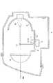
図2は、ヘッドランプ50の一例を概略的に示す断面図である。 FIG. 2 is a cross-sectional view schematically showing an example of the
図2に示す例では、ヘッドランプ50は、プロジェクタ型のヘッドランプであり、主に、光源51を構成するバルブ80と、投影レンズ82と、リフレクタ84と、これらを保持するホルダ86とを含む。リフレクタ84と投影レンズ82との間には配光切替シェード70が設けられる。ヘッドランプ50は、バルブ80から出射した光をリフレクタ84に反射させ、リフレクタ84から前方に向かう光の一部を配光切替シェード70で遮蔽して、車両前方に配光パターンを投影する。バルブ80は、白熱球やハロゲンランプ、放電球、LED等であってよい。リフレクタ84は、車両前後方向に延びる光軸を中心軸とする略楕円球面状の反射面を有している。投影レンズ82は、前方側表面が凸面で後方側表面が平面の平凸非球面レンズであり、光軸上に配置されている。 In the example shown in FIG. 2, the
ヘッドランプ50は、ヘッドランプ50の光軸の向きを略水平面内で変化させるスイブルモータ52を備える。スイブルモータ52は、ホルダ86の下底部に取り付けられ、軸52aのまわりにホルダ86を回動可能に支持している。ホルダ86がスイブルモータ52により回転駆動(スイブル)されることで、ヘッドランプ50の光軸の向きを略水平面内で変化される。 The
ヘッドランプ50は、バルブ80から発せられる光の一部を遮蔽した配光パターンを形成する配光切替シェード70を備える。配光切替シェード70は、2つのサブシェードから構成されている(図3参照)。配光切替シェード70は、その開閉状態がシェード駆動用アクチュエータ71により駆動制御される。図示の例では、配光切替シェード70は、回転軸74a,76b(図3参照)のまわりに回動可能に支持され、シェード駆動用アクチュエータ71により回転駆動される。配光切替シェード70は、シェード駆動用アクチュエータ71により回転駆動されることで、ハイビームパターンと、ロービームパターンと、スプリットビームパターンの少なくとも3種類のパターン(図5参照)を選択的に生成するように構成される。シェードの構造および作用(各パターン)の一例については、図3等を参照して詳述する。 The
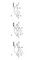
図3は、配光切替シェード70の一例を概略的に示す図であり、光軸方向に視た図である。図3には、概略的に、配光切替シェード70との関係でヘッドランプ50の照射部分の範囲が示される。尚、照射部分は、投影レンズ82により反転される。図3において、(A)は、ハイビームパターンを形成する際の配光切替シェード70の状態を示し、(B)は、スプリットビームパターンを形成する際の配光切替シェード70の状態を示し、(C)は、ロービームパターンを形成する際の配光切替シェード70の状態を示す。 FIG. 3 is a diagram schematically illustrating an example of the light
図3に示す配光切替シェード70は、2つのサブシェードとして、片側ハイビーム用シェード74と、ロービーム用シェード76とを備える。片側ハイビーム用シェード74は、ヘッドランプ50の照射部分の下半分の水平方向の片側のみを遮蔽するような長さを有する。片側ハイビーム用シェード74は、左右のヘッドランプ50L,50Rにおいて、車両中心側が遮蔽されるように左右逆側に設けられる。他方、ロービーム用シェード76は、ヘッドランプ50の照射部分の下半分の水平方向の全体を遮蔽するような長さを有する。片側ハイビーム用シェード74は、回転軸74aまわりに略鉛直面(光軸に垂直な面)内で回転可能に支持され、ロービーム用シェード76は、回転軸76aまわりに略鉛直面内で回転可能に支持される。片側ハイビーム用シェード74及びロービーム用シェード76は、それぞれに対して設けられるシェード駆動用アクチュエータ71によりそれぞれ回転駆動される。これにより、片側ハイビーム用シェード74及びロービーム用シェード76は、それぞれ退避位置と遮蔽位置との間で独立して切替可能となる。尚、片側ハイビーム用シェード74及びロービーム用シェード76は、他の態様で駆動されてもよい。片側ハイビーム用シェード74及びロービーム用シェード76は、例えばソレノイドにより駆動されてもよいし、併進駆動されてもよい。 The light
図4は、配光切替シェード70により実現される配光パターンの代表的な例を概略的に示す図である。 FIG. 4 is a diagram schematically showing a typical example of a light distribution pattern realized by the light
図4(A)は、ヘッドランプ50により生成されるハイビームパターンの一例を示す。このハイビームパターンは、左右のヘッドランプ50L,50Rの双方の片側ハイビーム用シェード74及びロービーム用シェード76を退避位置(図3(A)参照)に保持することにより形成される。 FIG. 4A shows an example of a high beam pattern generated by the
図4(B)は、ヘッドランプ50により生成されるスプリットビームパターンの一例を示す。図4(B)には、片側ハイビーム用シェード74の縁部74b(図3(B)参照)により境界付けられるカットオフラインCL,CRが示されている。このスプリットビームパターンは、左右のヘッドランプ50L,50Rの片側ハイビーム用シェード74を遮蔽位置に保持すると共に、左右のヘッドランプ50L,50Rのロービーム用シェード76を退避位置(図3(B)参照)に保持することにより形成される。スプリットビームパターンは、ハイビームパターンにおける一部領域がカットオフラインCL,CRを境界にして遮蔽されたパターンである。図4(B)に示す例では、スプリットビームパターンは、ハイビームパターンにおける車幅方向の車両中心側(光軸側)の領域が遮蔽されている。カットオフラインCL,CR間の距離L(即ち水平方向の遮蔽幅L)は、左右のヘッドランプ50L,50Rのスイブル角(即ち光軸の向き)を制御することで可変(伸縮)することができる。 FIG. 4B shows an example of a split beam pattern generated by the
図4(C)は、ヘッドランプ50により生成されるロービームパターンの一例を示す。このロービームパターンは、左右のヘッドランプ50L,50Rの片側ハイビーム用シェード74を退避位置に保持すると共に、左右のヘッドランプ50L,50Rのロービーム用シェード76を遮蔽位置(図3(C)参照)に保持することにより形成される。 FIG. 4C shows an example of a low beam pattern generated by the
図5は、本実施例の制御ECU40の主要な機能の一例を示すブロック図である。制御ECU40は、上述の如く、主なる機能として、点消灯制御部44と、ハイビーム配光可変制御部46と、AFS制御部48とを含む。 FIG. 5 is a block diagram illustrating an example of main functions of the
点消灯制御部44は、制御切替スイッチ20の状態に基づいて、ヘッドランプ50のON/OFFの切り替え制御を行う。なお、点消灯制御部44は、日照センサの出力信号等に基づいて、周囲が暗くなったときに自動的にヘッドランプ50をオンする制御を実行してもよい。 The on / off
ハイビーム配光可変制御部46は、制御切替スイッチ20の状態に基づいて、ハイビーム配光可変制御がオンであるとき、所定条件下(図6を参照して後述)でハイビーム配光可変制御を実行する。ハイビーム配光可変制御は、前方車両の検出結果に基づいて、車両前方を照明するための照明光の配光を制御して、前方車両の運転者等に対するグレアの低減を図る制御である。 The high beam distribution
ハイビーム配光可変制御部46は、図5に示すように、画像認識部46aと、ランプシェード制御部46bと、スイブル制御部46cとを含む。 As shown in FIG. 5, the high beam light distribution
画像認識部46aは、画像センサ10から得られる前方環境画像を画像処理して、車両前方に存在しうる前方車両(先行車や対向車)を検出する。画像中の前方車両を検出する方法は、多種多様であり、任意の方法が採用されてもよい。典型的には、前方車両は、移動体であり、ブレーキランプ(又はテールランプ)やヘッドランプから光を発すると共に、後方から受けた光を反射する反射部(リフレクタ)を車両後部に備える。従って、かかる光の特徴に基づいて、画像中の前方車両を検出してもよい。例えば、画像中の光(高輝度点)の特徴が所定の条件(明るさ、色、大きさ、エッジ形状のパターン、動き等)を満たす場合に、当該光に関する像が、前方車両として検出されてもよい。より具体的には、前方車両検出方法の一例として、画像センサ10から得られる前方環境画像を画像処理して、画像中の光(所定輝度以上の画素)を検出し、検出した光の中から、明るさ・光の動き(例えば光の物体の速度、進行方向等)・色(例えば、ブレーキランプの発光色や反射部の反射光の色等)の要素に基づいて、当該光が前方車両によるものか或いは前方車両以外の外乱光(道路標識の反射板等による反射光)なのかを判断するものであってよい。画像認識部46aは、前方車両の存在を検出すると、当該前方車両の位置や方位等を算出してもよい。 The
ランプシェード制御部46bは、シェード駆動用アクチュエータ71を介して配光パターンを制御する。具体的には、ランプシェード制御部46bは、画像認識部46aの前方車両の検出状況に基づいて、シェード駆動用アクチュエータ71により配光切替シェード70を制御して、ヘッドランプ50の配光パターンを制御する。基本的には、ランプシェード制御部46bは、画像認識部46aにより検出された前方車両の位置及び方向等に基づいて、当該前方車両がハイビームにより照射されないように片側ハイビーム用シェード74及びロービーム用シェード76の開閉状態を制御する。尚、ハイビーム配光可変制御部46のランプシェード制御部46bによる制御方法の詳細は後述する。 The lamp
スイブル制御部46cは、スイブルモータ52を介して配光パターンの照射方向(ヘッドランプ50のスイブル角)を制御する。具体的には、スイブル制御部46cは、画像認識部46aの前方車両の検出状況に基づいて、スイブルモータ52によりヘッドランプ50の光軸方向を制御する。基本的には、スイブル制御部46cは、画像認識部46aにより検出された前方車両の位置及び方向等に基づいて、当該前方車両がハイビームにより照射されないようにヘッドランプ50の光軸の向きを制御する。尚、ハイビーム配光可変制御部46のスイブル制御部46cによる制御方法の詳細は後述する。 The swivel control unit 46 c controls the irradiation direction of the light distribution pattern (the swivel angle of the headlamp 50) via the
AFS制御部48は、制御切替スイッチ20の状態に基づいて、AFS制御がオンであるとき、所定条件下(図6を参照して後述)でAFS制御を実行する。AFS制御は、コーナリング時等において、ステアリングの舵角や車速に応じて、ステアリング操舵方向(車両進行方向)にヘッドランプ50の光軸を向けて運転者の視認性向上を図る制御である。AFS制御部48は、AFS制御中、ステアリングの舵角や車速に応じて、目標スイブル角(以下、AFS制御位置という)を決定し、決定したAFS制御位置が実現されるようにスイブルモータ52(ヘッドランプ50の光軸の向き)を制御する。尚、AFS制御位置の決定方法は、任意であってよい。例えば、AFS制御位置は、舵角及び車速の検出結果に基づいて予測した所定時間後(例えば3秒後)の車両の進行方向に適合するように、決定されてもよい。また、AFS制御位置は、舵角及び車速に加えて若しくはそれに代えて、ナビゲーション装置からの情報(車両位置や車両前方のカーブの曲率半径等)に基づいて予測した所定時間後の車両の進行方向に適合するように、決定されてもよい。尚、左右のヘッドランプ50L,50RのAFS制御位置は、左右で異なる値であってもよい。 Based on the state of the control changeover switch 20, the
図6は、本実施例の制御ECU40により実現される主要処理の一例を示すフローチャートである。図6に示す処理は、車両の走行中に所定周期で繰り返し実行されてもよい。図7は、図6に示す処理に関連した説明図であり、前方車両の位置(θ)に応じた配光パターンの変化例を示す図である。 FIG. 6 is a flowchart illustrating an example of main processing realized by the
ステップ602では、制御切替スイッチ20の状態に基づいて、ヘッドランプ50がオンしているか否かが判定される。ヘッドランプ50がオンしている場合は、ステップ604に進み、それ以外の場合は、そのまま終了し、次の処理周期でステップ602からの処理を行う。 In
ステップ603では、制御切替スイッチ20の状態に基づいて、AFS制御がオンしているか否かが判定される。AFS制御がオンしている場合は、ステップ604に進み、それ以外の場合は、そのまま終了し、次の処理周期でステップ602からの処理を行う。 In
ステップ604では、制御切替スイッチ20の状態に基づいて、ハイビーム配光可変制御がオンしているか否かが判定される。ハイビーム配光可変制御がオンしている場合は、ステップ605に進み、それ以外の場合は、そのまま終了し、次の処理周期でステップ602からの処理を行う。尚、本例では、AFS制御がオンしている場合に限り、ハイビーム配光可変制御が実行可能とされている。 In
ステップ605では、ハイビーム配光可変制御部46の画像認識部46aは、画像センサ10からリアルタイムで提供される前方環境画像を画像処理して、車両前方に存在しうる前方車両(ハイビーム配光可変制御の制御対象となる先行車や対向車)を検出したか否かを判定する。前方車両を検出しない場合は、ステップ615に進む。他方、前方車両を検出した場合には、前方車両の横位置(方位)θを算出し、前方車両の横位置θに応じて、ステップ606又はステップ613に進む。ここで、前方車両の横位置θは、車両の進行方向(前後軸)を中心(ゼロ度)として規定された扇形領域内の前方車両の左右方向の位置を表してよい。例えば、前方車両の横位置θの絶対値が所定角度θ1より小さい場合は、ステップ606に進み、前方車両の横位置θの絶対値が所定角度θ1より大きい場合は、ステップ613に進む。In step 605, the
ステップ606では、スプリットビーム条件が成立したと判断して、ステップ607に進む。尚、この際、スプリットビーム条件が成立したことを表すフラグがセットされてもよい。 In
ステップ607では、AFS制御部48は、AFS制御を停止する又はAFS制御の停止状態を維持する。 In step 607, the
ステップ608では、ハイビーム配光可変制御部46は、ハイビーム配光可変制御を実行する。具体的には、上述の如く、ランプシェード制御部46bは、画像認識部46aにより検出された前方車両の位置及び方向等に基づいて、当該前方車両がハイビームにより照射されないように、左右のヘッドランプ50L,50Rのそれぞれにおける片側ハイビーム用シェード74及びロービーム用シェード76の開閉状態(退避位置と遮蔽位置の間の位置)を制御する。また、スイブル制御部46cは、画像認識部46aにより検出された前方車両の位置及び方向等に基づいて、当該前方車両がハイビームにより照射されないように左右のヘッドランプ50L,50Rの光軸の向き(カットオフラインCL,CRの位置)をそれぞれ制御する。例えば、図7(A)に示す例は、前方車両の横位置θが小さい(車両と同一の車線上に位置する)状況であり、かかる状況下では、ランプシェード制御部46bは、左右のヘッドランプ50L,50Rが共にスプリットビームパターンを形成するように、左右のヘッドランプ50L,50Rのシェード駆動用アクチュエータ71を制御する。また、スイブル制御部46cは、左側のヘッドランプ50LのカットオフラインCLが前方車両の左側端部から所定距離離間した位置に来、且つ、右側のヘッドランプ50RのカットオフラインCRが前方車両の右側端部から所定距離離間した位置に来るように、左右のヘッドランプ50L,50Rのスイブルモータ52を制御する。また、図7(B)に示す例は、前方車両の横位置θが所定角度θ1より小さいが比較的大きい(左隣の車線上に位置する)状況であり、かかる状況下では、ランプシェード制御部46bは、右のヘッドランプ50Rがスプリットビームパターンを形成し、且つ、左のヘッドランプ50Lがロービームパターンを形成するように、シェード駆動用アクチュエータ71を制御する。また、スイブル制御部46cは、右側のヘッドランプ50RのカットオフラインCRが前方車両の右側端部から所定距離離間した位置に来るように、右のヘッドランプ50Rのスイブルモータ52を制御する。尚、この際、左のヘッドランプ50Lのスイブル角は、任意であってよく、中立角で固定されてもよいし、右側のヘッドランプ50Rのスイブル角に応じて可変されてもよい。 In
ステップ609では、ハイビーム配光可変制御部46の画像認識部46aは、画像センサ10からリアルタイムで提供される前方環境画像を画像処理して、既に検出している前方車両を依然として検出しているか否かを判定する。前方車両を消失した場合、即ち前方車両が検出できなくなった場合は、ステップ610に進む。他方、前方車両を依然として検出している場合には、前方車両の横位置(方位)θを算出し、上記ステップ605と同様、前方車両の横位置θに応じて、ステップ608又はステップ613に進む。このようにして、一旦、前方車両が検出されると、その後、前方車両が検出されなくなるまで、ハイビーム配光可変制御が実行され(ステップ608)又はロービームパターンが形成される(ステップ614)。 In
ステップ610では、ハイビーム配光可変制御部46のスイブル制御部46cは、スプリットビームパターンによる遮蔽部分が段階的に閉じていく態様でスプリットビームパターンのカットオフラインCL、CRの位置を制御する。即ち、スイブル制御部46cは、左右のヘッドランプ50L,50Rが形成するスプリットビームパターンの全体としての遮蔽領域が徐々に小さくなる態様でスプリットビームパターンのカットオフラインCL、CRの位置を制御する。図4に示した配光パターンの例では、スイブル制御部46cは、カットオフラインCL、CRによる水平方向の遮蔽幅Lが徐々に小さくなるように、左右のヘッドランプ50L,50Rのスイブルモータ52を制御する。 In step 610, the swivel control unit 46c of the high beam variable light
この際、スイブル制御部46cは、好ましくは、AFS制御位置に向けて左右のヘッドランプ50L,50Rのスイブルモータ52を制御する。これにより、スプリットビームパターンによる遮蔽部分がAFS制御位置に向けて段階的に閉じていく態様で遮蔽部分を無くしていくことができる。尚、この目的のため、AFS制御位置は、上記ステップ607のAFS制御停止中もバックグランドで算出されていてもよいし、或いは、ステップ609の否定判定時に算出されていてもよい。 At this time, the swivel control unit 46c preferably controls the
尚、スプリットビームパターンによる遮蔽部分を段階的に閉じるのにかける時間は、瞬時ではなく、比較的長い時間(秒単位のオーダであり、例えば、2−7秒の間)である。この時間は、前方車両の消失を確定的に判定するのに要する時間に対応してもよく、AFS制御への遷移までの時間短縮(応答性)と前方車両消失判定の信頼性の両立の観点から適合されてもよい。 It should be noted that the time taken to close the shielded portion by the split beam pattern in stages is not instantaneous, but is a relatively long time (in the order of seconds, for example, 2-7 seconds). This time may correspond to the time required to determine the disappearance of the preceding vehicle deterministically. From the viewpoint of both shortening the time until the transition to the AFS control (responsiveness) and the reliability of determining the disappearance of the preceding vehicle. May be adapted from
ステップ611では、ランプシェード制御部46bは、左右のヘッドランプ50L,50Rの配光パターンをハイビームパターンに切り替える。この際、ランプシェード制御部46bは、上記ステップ610で段階的に閉じていくスプリットビームパターンによる遮蔽部分が所定基準以下まで小さくなった段階で、左右のヘッドランプ50L,50Rの配光パターンをハイビームパターンに切り替えてもよい。この場合、所定基準は、遮蔽幅Lの最小値又はゼロに対応してもよいし、AFS制御位置での遮蔽幅Lに対応してもよい。即ち、後者の場合、ランプシェード制御部46bは、AFS制御位置が実現された段階で、左右のヘッドランプ50L,50Rの配光パターンをハイビームパターンに切り替えることとなる。 In step 611, the
ステップ612では、上記ステップ607で停止したAFS制御が再開可能とされる。尚、ハイビーム配光可変制御が上記ステップ611にてAFS制御位置に向けてスイブル角を制御しつつ終了される場合には、AFS制御部48は、AFS制御を速やかに再開することが可能である。即ち、AFS制御は、ハイビーム配光可変制御の終了時から実質的に移行期間無しで再開することができる。本ステップ612の処理が終了すると、次の処理周期でステップ602からの処理を行う。尚、次周期でロービーム条件又はハイビーム条件が成立すると(ステップ613,ステップ615)、AFS制御が実際に再開されることになる。 In
ステップ613では、ロービーム条件が成立したと判断して、ステップ614に進む。尚、この際、ロービーム条件が成立したことを表すフラグがセットされてもよい。 In step 613, it is determined that the low beam condition is satisfied, and the process proceeds to step 614. At this time, a flag indicating that the low beam condition is established may be set.
ステップ614では、ランプシェード制御部46bは、左右のヘッドランプ50L,50Rの配光パターンをロービームパターンに切り替える又はロービームパターンで維持する(図7(C)参照)。この際、AFS制御部48は、ロービームパターンが形成される状態で、AFS制御を実行してもよい。 In step 614, the
ステップ615では、ハイビーム条件が成立したと判断して、ステップ616に進む。尚、この際、ハイビーム条件が成立したことを表すフラグがセットされてもよい。 In
ステップ616では、ランプシェード制御部46bは、その時点でロービームパターンが形成されている場合は、当該ロービームパターンを一定時間維持した後、ステップ617に進む。他方、既にハイビームパターンが形成されている場合は、そのままステップ617に進む。 In
ステップ617では、ランプシェード制御部46bは、左右のヘッドランプ50L,50Rの配光パターンをハイビームパターンに切り替える又はハイビームパターンで維持する。この際、AFS制御部48は、ハイビームパターンが形成される状態で、AFS制御を実行してもよい。 In step 617, the lamp
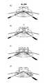
図8は、図6に示す処理に関連した説明図であり、前方車両消失時の配光パターンの変化態様の一例を示す図である。 FIG. 8 is an explanatory diagram related to the process shown in FIG. 6, and is a diagram illustrating an example of a change pattern of the light distribution pattern when the front vehicle disappears.
図8(A)に示すような前方車両が検出されている状況下では、前方車両がハイビームにより照射されないようにスプリットビームパターンが形成されると共に、スプリットビームパターンのカットオフラインCL、CRの位置が制御される(図6のステップ608)。その後、図8(B)に示すように、検出していた前方車両が検出されなくなると(図6のステップ609の否定判定)、左右のヘッドランプ50L,50Rが形成するスプリットビームパターンの全体としての遮蔽領域X1が、運転者にとって違和感となり、且つ、視認性の低下を招くことになる。このため、図8(C)に示すように、遮蔽領域X1が段階的に閉じられていき(図6のステップ610)、図8に示す例では、最終的には、遮蔽領域X1が無くなり、図8(D)に示すように、ハイビームパターンへと切り替わる(図6のステップ611)。 In a situation where a front vehicle as shown in FIG. 8A is detected, a split beam pattern is formed so that the front vehicle is not irradiated with a high beam, and the positions of the cut-off lines CL and CR of the split beam pattern are It is controlled (
このように図6に示す処理によれば、検出していた前方車両が検出不能となった場合に、スプリットビームパターンの遮蔽領域X1が段階的に減少されるので、運転者の違和感や視認性の低下を防止することができる。また、仮に瞬間的な前方車両の消失(車間距離の変化や、遮蔽物や検出精度等に起因した消失)であってその後に再度検出される場合のように、消失と再検出を繰り返す場合でも、それに応じてカットオフラインCL、CRの位置が僅かに動くだけであるので、スプリットビームパターンとハイビームパターンとが瞬間的に交互に入れ替わる場合に比べて、チャタリングによる違和感を低減することができる。尚、前方車両が検出不能となる事象は、上述のように前方車両との車間距離の変化や相対的な方位の変化や、前方車両との間の遮蔽物の存在等に起因して生じる事象であり、システム故障(例えば画像センサ10の故障等)に起因して前方車両が検出されない事象は除かれる。 As described above, according to the processing shown in FIG. 6, when the detected preceding vehicle becomes undetectable, the shielding region X1 of the split beam pattern is decreased step by step. Can be prevented. Even if the vehicle disappears and re-detects repeatedly, as in the case of a momentary disappearance of the preceding vehicle (change due to inter-vehicle distance, disappearance due to shielding, detection accuracy, etc.) Accordingly, since the positions of the cut-off lines CL and CR are slightly moved in response to this, it is possible to reduce a sense of incongruity due to chattering as compared with the case where the split beam pattern and the high beam pattern are alternately switched instantaneously. In addition, the event that the preceding vehicle cannot be detected is an event that occurs due to a change in the inter-vehicle distance from the preceding vehicle, a change in relative orientation, or the presence of a shield with the preceding vehicle, as described above. Thus, an event in which the vehicle ahead is not detected due to a system failure (for example, a failure of the image sensor 10 or the like) is excluded.
更に、スプリットビームパターンの遮蔽領域X1をAFS制御位置に向けて段階的に閉じる場合には、ハイビーム配光可変制御からAFS制御の移行をシームレスに実現することができる。即ち、ハイビームパターンに切り替わった後でAFS制御を実施する際、スイブルモータ52をAFS制御位置に移動させる必要がないことにより配光変化の違和感が無くなると共に、遅延無く速やかにAFS制御に遷移することができる。 Furthermore, when the shield region X1 of the split beam pattern is closed stepwise toward the AFS control position, the transition from the high beam light distribution variable control to the AFS control can be realized seamlessly. That is, when the AFS control is performed after switching to the high beam pattern, it is not necessary to move the
但し、AFS制御位置等に依存して、AFS制御位置おいて遮蔽領域X1が完全に無くならない場合がありうる。しかしながら、この場合も、ハイビームパターンに切り替わった後でAFS制御を実施する際、スイブルモータ52をAFS制御位置に移動させる量が低減することにより配光変化の違和感が低減すると共に、比較的速やかにAFS制御に遷移することができる。また、この場合、遮蔽領域X1が完全に無くなるスイブル角(AFS制御位置とは無関係な角又はAFS制御位置に対して所定の関係を有する角)までスイブルさせた後、スプリットビームパターンからハイビームパターンへ切り替え、その後、AFS制御位置へとスイブルさせてAFS制御に遷移することとしてもよい。 However, depending on the AFS control position or the like, the shielding region X1 may not be completely eliminated at the AFS control position. However, in this case as well, when the AFS control is performed after switching to the high beam pattern, the amount of movement of the
図9は、図6に示す処理に関連した説明図であり、コーナリング中における前方車両消失時のAFS制御位置と遮蔽領域X1との関係の例を上面視で示す図である。図9においては、スプリットビームパターンの全体としての照射領域が符号Sにより指示されている。図9(A)は、前方車両消失時のAFS制御位置がスプリットビームパターンの遮蔽領域X1内に存在する場合を示す。この場合、前方車両消失時には、図6のステップ610の処理により、図9(A)にて矢印で模式的に示すように、カットオフラインCL、CRがそれぞれに対して近接する方向に閉じられていく。図9(B)は、前方車両消失時のAFS制御位置がスプリットビームパターンの遮蔽領域X1外に存在する場合を示す。この場合、前方車両消失時には、図6のステップ610の処理により、図9(A)にて矢印で模式的に示すように、カットオフラインCL、CRが左方向(カーブの曲率中心側から離反する方向)に移動しつつ閉じられていく。 FIG. 9 is an explanatory diagram related to the processing shown in FIG. 6, and is a diagram showing an example of the relationship between the AFS control position and the shielding area X1 when the front vehicle disappears during cornering in a top view. In FIG. 9, an irradiation region as a whole of the split beam pattern is indicated by a symbol S. FIG. 9A shows a case where the AFS control position when the front vehicle disappears exists in the shielded region X1 of the split beam pattern. In this case, when the vehicle ahead disappears, the processing in step 610 in FIG. 6 causes the cut-off lines CL and CR to be closed in directions approaching each other, as schematically shown by arrows in FIG. 9A. Go. FIG. 9B shows a case where the AFS control position when the vehicle ahead disappears exists outside the shielding region X1 of the split beam pattern. In this case, when the preceding vehicle disappears, the cut-off lines CL and CR are separated from the left side (curvature center side of the curve) by the processing of step 610 in FIG. 6 as schematically shown by the arrows in FIG. The direction is closed while moving.
以上、本発明の好ましい実施例について詳説したが、本発明は、上述した実施例に制限されることはなく、本発明の範囲を逸脱することなく、上述した実施例に種々の変形及び置換を加えることができる。 The preferred embodiments of the present invention have been described in detail above. However, the present invention is not limited to the above-described embodiments, and various modifications and substitutions can be made to the above-described embodiments without departing from the scope of the present invention. Can be added.
例えば、上述した実施例では、カットオフラインCL、CRの位置がスイブル角により可変される構成の配光切替シェード70が使用されている。この場合、図6のステップ610の処理中、配光切替シェード70の開閉状態(退避位置と遮蔽位置の間の位置)は維持されたままとなる。しかしながら、配光切替シェード70の構成は、多種多様であり(例えば、特開2009−227088号や特開2010−000957号等)、任意の構成が採用されてもよい。また、配光切替シェードは、左右にスライド可能に構成されてもよい。この場合は、配光切替シェードのスライド動作により図6のステップ610の処理が実現されてもよい。また、配光切替シェードは、図10に示すように、上下方向で遮蔽領域を変化させるように構成されてもよい。図10には、横方向のカットオフラインCHの上下方向の位置が変化する態様が点線にて示されている。 For example, in the above-described embodiment, the light
また、図11に示すように、ハイビーム照射エリアを複数に分割し(図示の例では、8×4)、それぞれのエリアを点消灯(例えばLED光源により)することによって、ハイビーム配光可変制御を実行することも可能である。この場合、図11(A)に示すように、前方車両Z1,Z2に対応する各エリアA1,A2が遮蔽範囲として消灯される。そして、図11(B)に示すように、前方車両Z2が検出されなくなった際には、前方車両Z2に対応するエリアA2の配光をPWM制御等により段階的に消灯状態から点灯状態(図11(C))に遷移させることとしてよい。これにより、視認性の違和感を低減することができる。尚、図11に示す例では、スイブルモータ52を用いて遮蔽領域を制御しないので、前方車両消失時のAFS制御位置へのスイブル動作が不要である。 In addition, as shown in FIG. 11, the high beam irradiation variable control is performed by dividing the high beam irradiation area into a plurality of parts (8 × 4 in the illustrated example) and turning on and off each area (for example, by an LED light source). It is also possible to execute. In this case, as shown in FIG. 11A, the areas A1 and A2 corresponding to the preceding vehicles Z1 and Z2 are turned off as the shielding range. Then, as shown in FIG. 11B, when the forward vehicle Z2 is no longer detected, the light distribution in the area A2 corresponding to the forward vehicle Z2 is gradually turned on from the off state by PWM control or the like (FIG. 11B). 11 (C)). Thereby, the uncomfortable feeling of visibility can be reduced. In the example shown in FIG. 11, since the shielding area is not controlled using the
1 車両配光制御装置
10 画像センサ
20 制御切替スイッチ
40 制御ECU
44 点消灯制御部
46 ハイビーム配光可変制御部
46a 画像認識部
46b ランプシェード制御部
46c スイブル制御部
48 AFS制御部
50(50L,50R) ヘッドランプ
52 スイブルモータ
70 配光切替シェード
71 シェード駆動用アクチュエータ
74 片側ハイビーム用シェード
76 ロービーム用シェード
80 バルブ
82 投影レンズ
84 リフレクタ
86 ホルダDESCRIPTION OF SYMBOLS 1 Vehicle light distribution control apparatus 10 Image sensor 20
44
Claims (3)
Translated fromJapanese前記照明装置を制御する制御装置とを備え、
前記制御装置は、前方車両を検出した場合に、照明装置による配光パターンを前記スプリットビームパターンに切り替えると共に、前記前方車両が前記照明光により照射されないようにスプリットビームパターンのカットオフラインの位置を制御し、
前記制御装置は、前記前方車両を検出しなくなった場合に、前記スプリットビームパターンの遮蔽領域が徐々に小さくなる態様で前記スプリットビームパターンのカットオフラインの位置を制御しつつ前記スプリットビームパターンを維持し、前記遮蔽領域が所定基準以下まで小さくなった段階で、前記スプリットビームパターンから前記ハイビームパターンへと切り替えることを特徴とする、車両配光制御装置。An illumination device that irradiates illumination light in front of a vehicle, wherein a light distribution pattern is formed between a high beam pattern, a low beam pattern, and a split beam pattern in which a part of the high beam pattern is shielded with a cutoff line as a boundary. An illuminating device that is controlled so as to be switched and controlled so that the optical axis direction changes in a substantially horizontal direction;
A control device for controlling the lighting device,
When the front vehicle is detected, the control device switches the light distribution pattern by the lighting device to the split beam pattern and controls the position of the cut-off line of the split beam pattern so that the front vehicle is not irradiated with the illumination light. And
The control device maintains the split beam pattern while controlling the position of the cut-off line of the split beam pattern in such a manner that the shielding area of the split beam pattern gradually decreases when the vehicle ahead is no longer detected. The vehicle light distribution control device, wherein the split beam pattern is switched to the high beam pattern when the shielding area becomes smaller than a predetermined reference.
Priority Applications (5)
| Application Number | Priority Date | Filing Date | Title |
|---|---|---|---|
| JP2011154913AJP5454523B2 (en) | 2011-07-13 | 2011-07-13 | Vehicle light distribution control device |
| PCT/IB2012/001365WO2013008085A1 (en) | 2011-07-13 | 2012-07-11 | Vehicle light distribution control device and vehicle light distribution control method |
| EP12743222.7AEP2731825B1 (en) | 2011-07-13 | 2012-07-11 | Vehicle light distribution control device and vehicle light distribution control method |
| CN201280033982.3ACN103648843B (en) | 2011-07-13 | 2012-07-11 | Vehicle light distribution control device and vehicle light distribution control method |
| US14/131,596US9193297B2 (en) | 2011-07-13 | 2012-07-11 | Vehicle light distribution control device and vehicle light distribution control method |
Applications Claiming Priority (1)
| Application Number | Priority Date | Filing Date | Title |
|---|---|---|---|
| JP2011154913AJP5454523B2 (en) | 2011-07-13 | 2011-07-13 | Vehicle light distribution control device |
Publications (2)
| Publication Number | Publication Date |
|---|---|
| JP2013018433A JP2013018433A (en) | 2013-01-31 |
| JP5454523B2true JP5454523B2 (en) | 2014-03-26 |
Family
ID=46604382
Family Applications (1)
| Application Number | Title | Priority Date | Filing Date |
|---|---|---|---|
| JP2011154913AActiveJP5454523B2 (en) | 2011-07-13 | 2011-07-13 | Vehicle light distribution control device |
Country Status (5)
| Country | Link |
|---|---|
| US (1) | US9193297B2 (en) |
| EP (1) | EP2731825B1 (en) |
| JP (1) | JP5454523B2 (en) |
| CN (1) | CN103648843B (en) |
| WO (1) | WO2013008085A1 (en) |
Cited By (1)
| Publication number | Priority date | Publication date | Assignee | Title |
|---|---|---|---|---|
| EP3932739A1 (en) | 2020-07-01 | 2022-01-05 | Mazda Motor Corporation | Headlight control system |
Families Citing this family (11)
| Publication number | Priority date | Publication date | Assignee | Title |
|---|---|---|---|---|
| DE102014210069A1 (en)* | 2014-05-27 | 2015-12-03 | Continental Automotive Gmbh | Sensorless BEMF measurement for current-controlled brushless motors |
| DE102014019344A1 (en)* | 2014-12-22 | 2016-06-23 | GM Global Technology Operations LLC (n. d. Ges. d. Staates Delaware) | Motor vehicle headlight, vehicle headlight system, motor vehicle and method for operating a motor vehicle |
| FR3046835B1 (en)* | 2016-01-20 | 2020-02-14 | Aml Systems | PROJECTOR FOR MOTOR VEHICLE WITH REDUCED MOBILE CUT - OFF SURFACE. |
| EP3591576A3 (en)* | 2017-01-20 | 2020-01-15 | Koito Manufacturing Co., Ltd. | Vehicle lamp system, vehicle lamp control apparatus, and vehicle lamp control method |
| KR101908423B1 (en)* | 2017-04-10 | 2018-10-16 | 엘지전자 주식회사 | Vehicle control device mounted on vehicle and vheicle control method thereof |
| CN109131041A (en)* | 2017-06-19 | 2019-01-04 | 深圳市绎立锐光科技开发有限公司 | A kind of vehicle self-adapting illumination device and lighting system |
| JP7020105B2 (en)* | 2017-12-25 | 2022-02-16 | コニカミノルタ株式会社 | Image forming apparatus, image forming system, and processing method |
| JP7184539B2 (en)* | 2018-05-24 | 2022-12-06 | スタンレー電気株式会社 | LIGHTING CONTROL DEVICE, VEHICLE LAMP, AND LIGHTING CONTROL METHOD |
| KR102602225B1 (en)* | 2018-11-27 | 2023-11-14 | 현대자동차주식회사 | Vehicle headlamp control system and control method capable of improving armaments |
| JP7653621B2 (en)* | 2021-11-11 | 2025-03-31 | パナソニックIpマネジメント株式会社 | Light source unit and vehicle |
| EP4560186A1 (en)* | 2023-11-27 | 2025-05-28 | ZKW Group GmbH | Illumination device for vehicle headlamps |
Family Cites Families (14)
| Publication number | Priority date | Publication date | Assignee | Title |
|---|---|---|---|---|
| JPH01289727A (en) | 1988-05-16 | 1989-11-21 | Nissan Motor Co Ltd | Headlamp device for vehicle |
| US6861809B2 (en) | 1998-09-18 | 2005-03-01 | Gentex Corporation | Headlamp control to prevent glare |
| US20040240224A1 (en)* | 2003-05-26 | 2004-12-02 | Tai-An Chiang | [power adjustableg headlight system] |
| JP4402909B2 (en)* | 2003-06-25 | 2010-01-20 | 日立オートモティブシステムズ株式会社 | Auto light device |
| US8007146B2 (en)* | 2007-09-14 | 2011-08-30 | Koito Manufacturing Co., Ltd. | Vehicle lamp |
| FR2923428B1 (en)* | 2007-11-13 | 2010-01-15 | Valeo Vision | METHOD FOR AUTOMATIC ADAPTATION TO ROAD TRAFFIC OF A LIGHT BEAM OF A PROJECTOR DEVICE. |
| DE102007056382A1 (en)* | 2007-11-22 | 2009-05-28 | Hella Kgaa Hueck & Co. | Projection headlight assembly for vehicles |
| JP5260098B2 (en) | 2008-03-21 | 2013-08-14 | 株式会社小糸製作所 | Vehicle headlamp device |
| JP2010000957A (en)* | 2008-06-20 | 2010-01-07 | Koito Mfg Co Ltd | Headlight device for vehicle |
| JP5362460B2 (en) | 2009-06-26 | 2013-12-11 | 株式会社小糸製作所 | Vehicle headlamp device |
| JP5438405B2 (en) | 2009-07-10 | 2014-03-12 | 株式会社小糸製作所 | Vehicle headlamp device |
| JP5398443B2 (en) | 2009-09-15 | 2014-01-29 | 株式会社小糸製作所 | Vehicle headlamp device |
| JP6001238B2 (en)* | 2011-02-14 | 2016-10-05 | 株式会社小糸製作所 | Light distribution control device for vehicle headlamp |
| JP5333539B2 (en)* | 2011-07-28 | 2013-11-06 | 株式会社デンソー | Headlamp light distribution control device |
- 2011
- 2011-07-13JPJP2011154913Apatent/JP5454523B2/enactiveActive
- 2012
- 2012-07-11WOPCT/IB2012/001365patent/WO2013008085A1/enactiveApplication Filing
- 2012-07-11CNCN201280033982.3Apatent/CN103648843B/enactiveActive
- 2012-07-11USUS14/131,596patent/US9193297B2/enactiveActive
- 2012-07-11EPEP12743222.7Apatent/EP2731825B1/enactiveActive
Cited By (1)
| Publication number | Priority date | Publication date | Assignee | Title |
|---|---|---|---|---|
| EP3932739A1 (en) | 2020-07-01 | 2022-01-05 | Mazda Motor Corporation | Headlight control system |
Also Published As
| Publication number | Publication date |
|---|---|
| WO2013008085A1 (en) | 2013-01-17 |
| EP2731825A1 (en) | 2014-05-21 |
| EP2731825B1 (en) | 2019-06-05 |
| JP2013018433A (en) | 2013-01-31 |
| US9193297B2 (en) | 2015-11-24 |
| CN103648843A (en) | 2014-03-19 |
| US20140145612A1 (en) | 2014-05-29 |
| CN103648843B (en) | 2016-03-23 |
Similar Documents
| Publication | Publication Date | Title |
|---|---|---|
| JP5454523B2 (en) | Vehicle light distribution control device | |
| JP5293893B2 (en) | VEHICLE LIGHTING DEVICE AND VEHICLE HEADLAMP CONTROL METHOD | |
| JP5719620B2 (en) | Light distribution control device for vehicle headlamp | |
| JP5438405B2 (en) | Vehicle headlamp device | |
| JP5454526B2 (en) | Vehicle light distribution control device and method | |
| CN102635823B (en) | Vehicle headlamp light distribution controller | |
| JP5362460B2 (en) | Vehicle headlamp device | |
| JP5546326B2 (en) | Control device, vehicle lamp system, vehicle lamp | |
| JP5398443B2 (en) | Vehicle headlamp device | |
| JP5666348B2 (en) | Light distribution control device for vehicle headlamp | |
| JP5372616B2 (en) | Light distribution control system for vehicle headlamps | |
| CN104411541A (en) | Headlamp light distribution control device for vehicle | |
| JP5430282B2 (en) | Light distribution control system for vehicle headlamps | |
| JP2011255825A (en) | Vehicular lighting fixture system, control device and vehicular lighting fixture | |
| JP2012218532A (en) | Lighting device for vehicle and method | |
| EP2384933B1 (en) | Vehicle headlamp system, control device and vehicle headlamp | |
| JP5636483B2 (en) | Light distribution control system for vehicle headlamps | |
| JP2014015170A (en) | Control device, headlight system for vehicle | |
| JP5557611B2 (en) | VEHICLE LIGHT SYSTEM, CONTROL DEVICE, AND VEHICLE LIGHT | |
| JP2012218587A (en) | Irradiation direction control device and irradiation direction control system | |
| JP2011238378A (en) | Lamp fixture system for vehicle, control device, and lamp fixture for vehicle | |
| JP2013145720A (en) | Vehicle headlamp and vehicle headlamp system | |
| JP5392226B2 (en) | Headlight control device | |
| JP2012218601A (en) | Device and system for controlling irradiation direction |
Legal Events
| Date | Code | Title | Description |
|---|---|---|---|
| A977 | Report on retrieval | Free format text:JAPANESE INTERMEDIATE CODE: A971007 Effective date:20130422 | |
| A131 | Notification of reasons for refusal | Free format text:JAPANESE INTERMEDIATE CODE: A131 Effective date:20130514 | |
| TRDD | Decision of grant or rejection written | ||
| A01 | Written decision to grant a patent or to grant a registration (utility model) | Free format text:JAPANESE INTERMEDIATE CODE: A01 Effective date:20131210 | |
| A61 | First payment of annual fees (during grant procedure) | Free format text:JAPANESE INTERMEDIATE CODE: A61 Effective date:20131223 | |
| R151 | Written notification of patent or utility model registration | Ref document number:5454523 Country of ref document:JP Free format text:JAPANESE INTERMEDIATE CODE: R151 |