JP5454255B2 - Acoustic signal processing apparatus and acoustic signal processing system - Google Patents
Acoustic signal processing apparatus and acoustic signal processing systemDownload PDFInfo
- Publication number
- JP5454255B2 JP5454255B2JP2010059464AJP2010059464AJP5454255B2JP 5454255 B2JP5454255 B2JP 5454255B2JP 2010059464 AJP2010059464 AJP 2010059464AJP 2010059464 AJP2010059464 AJP 2010059464AJP 5454255 B2JP5454255 B2JP 5454255B2
- Authority
- JP
- Japan
- Prior art keywords
- network
- frame
- acoustic signal
- transmission
- master
- Prior art date
- Legal status (The legal status is an assumption and is not a legal conclusion. Google has not performed a legal analysis and makes no representation as to the accuracy of the status listed.)
- Active
Links
- 238000012545processingMethods0.000titleclaimsdescription100
- 230000005540biological transmissionEffects0.000claimsdescription223
- 238000005070samplingMethods0.000claimsdescription30
- 230000001360synchronised effectEffects0.000claimsdescription12
- 238000000034methodMethods0.000description62
- 230000008569processEffects0.000description51
- 238000012546transferMethods0.000description49
- 230000008054signal transmissionEffects0.000description46
- 230000004044responseEffects0.000description14
- 230000006870functionEffects0.000description12
- 238000004891communicationMethods0.000description10
- 230000005236sound signalEffects0.000description10
- 238000012790confirmationMethods0.000description9
- 230000008859changeEffects0.000description7
- 230000006399behaviorEffects0.000description4
- 238000012986modificationMethods0.000description3
- 230000004048modificationEffects0.000description3
- 230000003111delayed effectEffects0.000description2
- 238000010586diagramMethods0.000description2
- 230000000644propagated effectEffects0.000description2
- 238000006243chemical reactionMethods0.000description1
- 230000001934delayEffects0.000description1
- 238000001514detection methodMethods0.000description1
- 239000012636effectorSubstances0.000description1
- 230000000694effectsEffects0.000description1
- 238000009432framingMethods0.000description1
- 239000004973liquid crystal related substanceSubstances0.000description1
- 238000004519manufacturing processMethods0.000description1
- 230000000737periodic effectEffects0.000description1
Images


Classifications
- H—ELECTRICITY
- H04—ELECTRIC COMMUNICATION TECHNIQUE
- H04L—TRANSMISSION OF DIGITAL INFORMATION, e.g. TELEGRAPHIC COMMUNICATION
- H04L12/00—Data switching networks
- H04L12/28—Data switching networks characterised by path configuration, e.g. LAN [Local Area Networks] or WAN [Wide Area Networks]
- H04L12/46—Interconnection of networks
- H04L12/4604—LAN interconnection over a backbone network, e.g. Internet, Frame Relay
- H04L12/462—LAN interconnection over a bridge based backbone
- H04L12/4625—Single bridge functionality, e.g. connection of two networks over a single bridge
- H—ELECTRICITY
- H04—ELECTRIC COMMUNICATION TECHNIQUE
- H04J—MULTIPLEX COMMUNICATION
- H04J3/00—Time-division multiplex systems
- H04J3/02—Details
- H04J3/06—Synchronising arrangements
- H04J3/0635—Clock or time synchronisation in a network
- H04J3/0685—Clock or time synchronisation in a node; Intranode synchronisation
- H04J3/0691—Synchronisation in a TDM node
- H—ELECTRICITY
- H04—ELECTRIC COMMUNICATION TECHNIQUE
- H04L—TRANSMISSION OF DIGITAL INFORMATION, e.g. TELEGRAPHIC COMMUNICATION
- H04L12/00—Data switching networks
- H04L12/28—Data switching networks characterised by path configuration, e.g. LAN [Local Area Networks] or WAN [Wide Area Networks]
- H04L12/40—Bus networks
- H04L12/40006—Architecture of a communication node
- H04L12/40013—Details regarding a bus controller
- H—ELECTRICITY
- H04—ELECTRIC COMMUNICATION TECHNIQUE
- H04L—TRANSMISSION OF DIGITAL INFORMATION, e.g. TELEGRAPHIC COMMUNICATION
- H04L12/00—Data switching networks
- H04L12/66—Arrangements for connecting between networks having differing types of switching systems, e.g. gateways
- H—ELECTRICITY
- H04—ELECTRIC COMMUNICATION TECHNIQUE
- H04L—TRANSMISSION OF DIGITAL INFORMATION, e.g. TELEGRAPHIC COMMUNICATION
- H04L65/00—Network arrangements, protocols or services for supporting real-time applications in data packet communication
- H04L65/60—Network streaming of media packets
- H04L65/70—Media network packetisation
- H—ELECTRICITY
- H04—ELECTRIC COMMUNICATION TECHNIQUE
- H04L—TRANSMISSION OF DIGITAL INFORMATION, e.g. TELEGRAPHIC COMMUNICATION
- H04L69/00—Network arrangements, protocols or services independent of the application payload and not provided for in the other groups of this subclass
- H04L69/28—Timers or timing mechanisms used in protocols
- H—ELECTRICITY
- H04—ELECTRIC COMMUNICATION TECHNIQUE
- H04L—TRANSMISSION OF DIGITAL INFORMATION, e.g. TELEGRAPHIC COMMUNICATION
- H04L12/00—Data switching networks
- H04L12/28—Data switching networks characterised by path configuration, e.g. LAN [Local Area Networks] or WAN [Wide Area Networks]
- H04L12/42—Loop networks
- H04L12/427—Loop networks with decentralised control
- H04L12/43—Loop networks with decentralised control with synchronous transmission, e.g. time division multiplex [TDM], slotted rings
- H—ELECTRICITY
- H04—ELECTRIC COMMUNICATION TECHNIQUE
- H04L—TRANSMISSION OF DIGITAL INFORMATION, e.g. TELEGRAPHIC COMMUNICATION
- H04L12/00—Data switching networks
- H04L12/28—Data switching networks characterised by path configuration, e.g. LAN [Local Area Networks] or WAN [Wide Area Networks]
- H04L12/2803—Home automation networks
- H04L2012/2847—Home automation networks characterised by the type of home appliance used
- H04L2012/2849—Audio/video appliances
Landscapes
- Engineering & Computer Science (AREA)
- Computer Networks & Wireless Communication (AREA)
- Signal Processing (AREA)
- Multimedia (AREA)
- Computer Security & Cryptography (AREA)
- Circuit For Audible Band Transducer (AREA)
- Small-Scale Networks (AREA)
- Synchronisation In Digital Transmission Systems (AREA)
Description
Translated fromJapaneseこの発明は、音響信号を伝送するネットワークに接続可能な音響信号処理装置と、このような音響信号処理装置を含む音響信号処理システムに関する。 The present invention relates to an acoustic signal processing device connectable to a network for transmitting an acoustic signal and an acoustic signal processing system including such an acoustic signal processing device.
従来から、複数のデバイス間でデータの伝送を行うための種々のネットワークシステムが知られている。
例えば、複数のノード間で音響信号の伝送を行うためのオーディオネットワークシステムが知られており、コンサート、演劇、音楽製作、構内放送等において用いられている。このようなオーディオネットワークシステムの例としては、以下の非特許文献1,2に記載のような、CobraNet(商標),EtherSound(商標)が知られている。Conventionally, various network systems for transmitting data between a plurality of devices are known.
For example, an audio network system for transmitting an acoustic signal between a plurality of nodes is known, and is used in concerts, plays, music production, private broadcasting, and the like. As examples of such an audio network system, CobraNet (trademark) and EtherSound (trademark) as described in Non-Patent
また、これら以外に、特許文献1に記載のネットワークシステムも提案されている。
この特許文献1に記載のネットワークシステムにおいては、システムを構成する各デバイスにより形成されるリング状の伝送路にフレームを定期的に循環させ、各デバイスがそのフレームに対して必要な情報を読み書きすることにより、システムを構成する任意のデバイスから任意のデバイスへ、音響信号だけでなくイーサネット(登録商標)フレーム等の制御信号も、安定して伝送することができる。In addition to these, a network system described in
In the network system described in
また、特許文献2には、このようにフレームを定期的に循環させるネットワークシステムにおいて、マスタノードがワードクロック(サンプリングクロック)を生成し、そのクロックに従ったタイミングでフレームを送信する一方、他のノードは、定期的なフレームの受信タイミングを基準に、これを適切な時間だけ遅延させてワードクロックを生成することが記載されている。このようにすることにより、各ノードにおいてマスタノードと同じ周期かつ同じ位相のワードクロックを生成することができる。すなわち、フレームの伝送により、同時にワードクロックも伝送することができる。 Further, in
ところで、上述した特許文献1及び2に記載のネットワークシステムにおいては、各デバイスで信号伝送用のフレームに対してデータの読み書きを行いつつ、所定の周期内にフレームに伝送路を1周させることが必要であった。
従って、システムに組み込むことのできるデバイスの数や、伝送路の物理的な長さ(主にデバイス間を接続するケーブルの長さに依存する)に制約があるという問題があった。By the way, in the network systems described in
Therefore, there is a problem that there are restrictions on the number of devices that can be incorporated into the system and the physical length of the transmission path (mainly depending on the length of the cable connecting the devices).
このような問題に対処するためには、ネットワークシステムに複数の伝送路に接続可能なブリッジデバイスを設け、そのブリッジデバイスにより複数の伝送路を接続した構成とすることが考えられる。
ここで、複数の伝送路を接続した構成を採る場合、システム全体を同じワードクロックに基づいて動作させようとすると、システム全体のワードクロック源となるデバイスが属する伝送路から、他の伝送路にワードクロックを適切に伝送する必要がある。In order to cope with such a problem, it is conceivable that a bridge device that can be connected to a plurality of transmission paths is provided in the network system, and the plurality of transmission paths are connected by the bridge device.
Here, when adopting a configuration in which a plurality of transmission paths are connected, if the entire system is operated based on the same word clock, the transmission path to which the device that is the word clock source of the entire system belongs is transferred to another transmission path. It is necessary to transmit the word clock appropriately.
また、ワードクロック源が別のデバイスに変更された場合には、変更前のワードクロック源がワードクロックの供給を停止してから、新たなワードクロック源からのワードクロックに基づくフレームの伝送が開始されるまでに、信号伝送が不能になる期間が生じてしまう。そして、ワードクロック源を、それまでと異なる伝送路に属するデバイスに変更する場合には、新たなワードクロック源からシステム全体にワードクロックを伝送する状態にシステムを移行させるために時間がかかり、信号伝送が不能になる期間長くなってしまうことが考えられる。 If the word clock source is changed to another device, the frame clock based on the word clock from the new word clock source starts after the word clock source before the change stops supplying the word clock. By the time, a period in which signal transmission is disabled occurs. And when changing the word clock source to a device belonging to a different transmission path, it takes time to shift the system to a state where the word clock is transmitted from the new word clock source to the entire system. It can be considered that the period during which transmission is disabled becomes longer.
この発明は、このような事情に鑑みてなされたものであり、システムを構成するデバイス間を循環させるフレームによりサンプリングクロックのタイミングを伝達する場合において、システムを複数の伝送路を接続した構成とする場合でも、クロック源を異なる伝送路のデバイスに変更したことに伴って生じる各伝送路における伝送不能時間を短縮することを目的とする。 The present invention has been made in view of such circumstances, and in a case where the timing of the sampling clock is transmitted by a frame that circulates between devices constituting the system, the system is configured by connecting a plurality of transmission paths. Even in such a case, an object is to shorten the transmission impossible time in each transmission line caused by changing the clock source to a device of a different transmission line.
上記の目的を達成するため、この発明の音響信号処理装置は、ネットワークを構成するデバイスの1つがマスタとして、その他のデバイスがスレーブとして動作し、マスタが所定のサンプリング周期毎に音声伝送フレームを生成して送出し、その音声伝送フレームがそのネットワークを構成する全てのデバイスを通過して上記マスタに戻り、そのネットワークを構成する各デバイスが、上記音声伝送フレームへ音響信号の書き込み及び/又は読み出しを行うことにより、その各デバイスのうち任意のデバイス間で音響信号の伝送が行われるネットワークに接続するためのインタフェースとして、それぞれ異なるネットワークに接続可能な第1インタフェース及び第2インタフェースを備える音響信号処理装置であって、上記第1インタフェースにより接続する第1ネットワークにおいてスレーブとして動作し、上記第2インタフェースにより接続する第2ネットワークにおいてマスタとして動作している状態において、上記第1ネットワークにおいて音声伝送フレームを継続的に受信している間は、その音声伝送フレームの受信タイミングに基づいてサンプリングクロックを生成し、その音声伝送フレームの受信が途絶えたら、独自のタイミングでサンプリングクロックを生成して、そのサンプリングクロックの周期毎に上記第2のネットワークにおいて上記音声伝送フレームを生成して送出し、上記第2ネットワークがリセットされた場合、その第2ネットワークにおいてスレーブとしての動作を開始し、その後、その第2ネットワークにおいて他のデバイスがマスタとして動作して送出した音声伝送フレームの継続的な受信を開始した場合に、上記第1ネットワークをリセットし、その第1ネットワークにおいてマスタとしての動作を開始するようにしたものである。 In order to achieve the above object, the acoustic signal processing apparatus according to the present invention operates such that one of the devices constituting the network operates as a master and the other devices operate as slaves, and the master generates an audio transmission frame at a predetermined sampling period. The audio transmission frame passes through all devices constituting the network and returns to the master, and each device constituting the network writes and / or reads an acoustic signal to the audio transmission frame. An acoustic signal processing apparatus including a first interface and a second interface that can be connected to different networks as interfaces for connecting to networks in which acoustic signals are transmitted between arbitrary devices among the devices. And the first interface While operating as a slave in the first network connected by the second network and operating as a master in the second network connected by the second interface, while the voice transmission frame is continuously received in the first network, Then, a sampling clock is generated based on the reception timing of the audio transmission frame. When reception of the audio transmission frame is interrupted, a sampling clock is generated at a unique timing, and the second network is generated every period of the sampling clock. When the second network is reset, the voice transmission frame is generated and transmitted at the start of the operation as a slave in the second network, and then another device operates as the master in the second network. If you start the continuous reception of the audio transport frame transmitted Te, it resets the first network, in which so as to start an operation as a master in its first network.
このような音響信号処理装置において、上記第1ネットワークにおける音声伝送フレームの送受信と上記第2ネットワークにおける音声伝送フレームの送受信とが同期していることを条件に、上記第1ネットワークにおける音声伝送フレームから読み出した音響信号を上記第2ネットワークにおける音声伝送フレームに書き込む第1伝送動作と、上記第2ネットワークにおける音声伝送フレームから読み出した音響信号を上記第1ネットワークにおける音声伝送フレームに書き込む第2伝送動作との少なくとも一方を行うようにするとよい。 In such an acoustic signal processing apparatus, on the condition that the transmission / reception of the audio transmission frame in the first network and the transmission / reception of the audio transmission frame in the second network are synchronized, the audio transmission frame in the first network A first transmission operation for writing the read acoustic signal in the voice transmission frame in the second network, and a second transmission operation for writing the acoustic signal read from the voice transmission frame in the second network in the voice transmission frame in the first network; It is good to perform at least one of these.
また、この発明の音響信号処理システムは、ブリッジデバイスで接続された第1ネットワークと第2ネットワークとを含む音響信号処理システムであって、上記第1ネットワークは、1以上の第1のデバイスと上記ブリッジデバイスとを接続して構成し、1つのデバイスがマスタとして、その他のデバイスがスレーブとして動作するものであり、上記第2ネットワークは、1以上の第2のデバイスと上記ブリッジデバイスとを接続して構成し、1つのデバイスがマスタとして、その他のデバイスがスレーブとして動作するものであり、上記第1ネットワークにおいては、上記第1のデバイスの1つがマスタとして動作して、所定のサンプリング周期毎に音声伝送フレームを生成して送出し、その音声伝送フレームはその第1ネットワークを構成する全てのデバイスを通過して上記マスタに戻り、上記第1ネットワークを構成する各デバイスが、上記音声伝送フレームへ音響信号の書き込み及び/又は読み出しを行うことにより、その各デバイスのうち任意のデバイス間で音響信号の伝送が行われ、上記ブリッジデバイスは、上記第1ネットワークにおいて音声伝送フレームを継続的に受信している間は、その音声伝送フレームの受信タイミングに基づいてサンプリングクロックを生成し、その音声伝送フレームの受信が途絶えたら、独自のタイミングでサンプリングクロックを生成するクロック発生部を備え、上記第2ネットワークにおいては、上記ブリッジデバイスがマスタとして動作して、上記クロック発生部が生成するサンプリングクロックの周期毎に音声伝送フレームを生成して送出し、その音声伝送フレームはその第2ネットワークを構成する全てのデバイスを通過して上記ブリッジデバイスに戻り、上記第2ネットワークを構成する各デバイスが、上記音声伝送フレームへ音響信号の書き込み及び/又は読み出しを行うことにより、その各デバイスのうち任意のデバイス間で音響信号の伝送が行われ、さらに、上記ブリッジデバイスは、上記第2ネットワークがリセットされた場合、その第2ネットワークにおいてスレーブとしての動作を開始し、その後、その第2ネットワークにおいて他のデバイスがマスタとして動作して送出した音声伝送フレームの継続的な受信を開始した場合に、上記第1ネットワークをリセットし、その第1ネットワークにおいてマスタとしての動作を開始するようにしたものである。 The acoustic signal processing system of the present invention is an acoustic signal processing system including a first network and a second network connected by a bridge device, wherein the first network includes one or more first devices and the above-described first device. A bridge device is connected and one device operates as a master and the other devices operate as slaves. The second network connects one or more second devices and the bridge device. One device operates as a master and the other devices operate as slaves. In the first network, one of the first devices operates as a master at every predetermined sampling period. An audio transmission frame is generated and transmitted, and the audio transmission frame configures the first network. The device returns to the master after passing through all the devices, and each device constituting the first network writes and / or reads an acoustic signal to and from the audio transmission frame, so that any device among the devices While the sound signal is transmitted between them, the bridge device generates a sampling clock based on the reception timing of the audio transmission frame while continuously receiving the audio transmission frame in the first network, When the reception of the voice transmission frame is interrupted, a clock generator that generates a sampling clock at a unique timing is provided. In the second network, the bridge device operates as a master, and the sampling generated by the clock generator Audio transmission frames are generated every clock cycle. The voice transmission frame passes through all devices constituting the second network and returns to the bridge device, and each device constituting the second network writes an acoustic signal to the voice transmission frame. And / or by reading out, an acoustic signal is transmitted between any of the devices, and the bridge device is a slave in the second network when the second network is reset. Then, when the second network starts continuous reception of the voice transmission frame transmitted by other devices operating as a master, the first network is reset and the first network is reset. Starts operation as a master in the network .
以上のようなこの発明の音響信号処理装置及び音響信号処理システムによれば、システムを構成するデバイス間を循環させるフレームによりサンプリングクロックのタイミングを伝達する場合において、システムを複数の伝送路を接続した構成とする場合でも、クロック源を異なる伝送路のデバイスに変更したことに伴って生じる各伝送路における伝送不能時間を短縮することができる。 According to the acoustic signal processing apparatus and the acoustic signal processing system of the present invention as described above, when the timing of the sampling clock is transmitted by a frame that circulates between devices constituting the system, the system is connected to a plurality of transmission paths. Even in the case of the configuration, it is possible to reduce the transmission impossible time in each transmission path caused by changing the clock source to a device of a different transmission path.
以下、この発明を実施するための形態を図面に基づいて具体的に説明する。
1. この発明の実施形態のオーディオネットワークシステムの概要
1.1 全体構成
まず図1に、この発明のネットワークシステムの実施形態であるオーディオネットワークシステムの概略構成を示す。
この図に示すように、オーディオネットワークシステムSは、第1部分ネットワークS1と第2部分ネットワークS2とを、ブリッジデバイスである第3入出力装置IO3により接続した構成となっている。Hereinafter, embodiments for carrying out the present invention will be specifically described with reference to the drawings.
1. 1. Outline of Audio Network System of Embodiment of Present Invention 1.1 Overall Configuration FIG. 1 shows a schematic configuration of an audio network system as an embodiment of the network system of the present invention.
As shown in this figure, the audio network system S has a configuration in which a first partial network S1 and a second partial network S2 are connected by a third input / output device IO3 that is a bridge device.
そして、第1部分ネットワークS1は、コンソールC1、第4入出力装置IO4及び第3入出力装置IO3を、実線で示す通信ケーブルCBによりカスケード状に接続するか、又は破線で示すケーブルも含めてループ状に接続したものである。
第2部分ネットワークS2は、第3入出力装置IO3、第2入出力装置IO2、第1入出力装置IO1及びミキサエンジンE1を、同様にカスケード状又はループ状に接続したものである。The first partial network S1 is a loop that includes the console C1, the fourth input / output device IO4, and the third input / output device IO3 connected in a cascade manner by the communication cable CB indicated by the solid line, or including the cable indicated by the broken line. Are connected in a shape.
The second partial network S2 is formed by similarly connecting the third input / output device IO3, the second input / output device IO2, the first input / output device IO1, and the mixer engine E1 in a cascade or loop form.
第3入出力装置IO3は、第1部分ネットワークS1に接続するためのネットワークI/F(インタフェース)と、第2部分ネットワークS2に接続するためのネットワークI/Fとを別々に持っている。そして、各部分ネットワークにおいて、その部分ネットワークに属するデバイスとして、その部分ネットワークに属する他のデバイスとの間でデータの送受信を行うと共に、一方の部分ネットワークに入力したデータを他方の部分ネットワークに伝達することもできる。そしてこのことにより、2つの部分ネットワークを接続するブリッジデバイスとして機能することができる。 The third input / output device IO3 has a network I / F (interface) for connecting to the first partial network S1 and a network I / F for connecting to the second partial network S2. In each partial network, as a device belonging to the partial network, data is transmitted to and received from other devices belonging to the partial network, and data input to one partial network is transmitted to the other partial network. You can also. This makes it possible to function as a bridge device that connects two partial networks.
また、第1〜第4入出力装置IO1〜IO4はそれぞれ、オーディオネットワークシステムSに対して外部から複数の音響信号を入力する複数の入力ポート及び/又は外部へ複数の音響信号を出力する複数の出力ポートを有する装置である。アナログ入出力を行う場合には、A/D変換器及びD/A変換器を備え、オーディオネットワークシステムSで扱うデジタル音響信号と、端子から入出力するアナログ音響信号との間の変換を行う。装置毎に入力あるいは出力のポート数やその他の機能が異なっていても構わない。
コンソールC1は、オーディオネットワークシステムSを構成する各デバイスに対する操作を受け付けるためのデバイスであり、多数の操作子や表示器を備えた操作パネルを有する。Further, the first to fourth input / output devices IO1 to IO4 each have a plurality of input ports for inputting a plurality of sound signals from the outside to the audio network system S and / or a plurality of sound signals for outputting a plurality of sound signals to the outside. A device having an output port. When analog input / output is performed, an A / D converter and a D / A converter are provided, and conversion between a digital acoustic signal handled by the audio network system S and an analog acoustic signal input / output from a terminal is performed. The number of input or output ports and other functions may be different for each device.
The console C1 is a device for accepting operations on each device constituting the audio network system S, and has an operation panel including a number of operators and displays.
ミキサエンジンE1は、各入出力装置から入力され、オーディオネットワークシステムS内を伝送される複数chの音響信号のうちの所望の音響信号を取り込んでミキシングするデバイスである。ミキサエンジンE1に取り込まれた複数の音響信号(波形データ)は、まず、複数の各入力chにて、コンプレッサ、イコライザ等の信号処理が施された後、レベル制御され複数通りにミキシングされる。 The mixer engine E1 is a device that takes in and mixes desired acoustic signals among a plurality of channels of acoustic signals that are input from each input / output device and transmitted through the audio network system S. A plurality of acoustic signals (waveform data) taken into the mixer engine E1 are first subjected to signal processing such as a compressor and an equalizer at a plurality of input channels, and then mixed in a plurality of ways with level control.
そしてミキシングにより得られた複数の音響信号は、さらに、出力chにて、コンプレッサ、イコライザ等の信号処理が施され、レベル制御されて、オーディオネットワークシステムSを介して各入出力装置に伝送され外部へ出力される。
また、ミキサエンジンE1自身も、ローカルの入力ポートや出力ポートを備えており、その入力ポートからの音響信号をミキシングの対象とすることができ、ミキシング結果の音響信号をその出力ポートに出力することができる。The plurality of acoustic signals obtained by mixing are further subjected to signal processing such as a compressor and an equalizer at the output channel, level-controlled, and transmitted to each input / output device via the audio network system S to be externally transmitted. Is output.
Also, the mixer engine E1 itself has a local input port and output port, and the acoustic signal from the input port can be the target of mixing, and the acoustic signal resulting from the mixing is output to the output port. Can do.
1.2 部分ネットワークの構成
次に、図2に、部分ネットワークの概略構成を示す。
図2(a),(b)に示すように、この部分ネットワークPは、それぞれ単方向の通信を行う受信手段である受信インタフェース(I/F)と送信手段である送信I/Fの組を2組備えたノードを、通信ケーブルCBで順次接続することにより構成したものである。これらの各ノードが、図1におけるコンソールC1、入出力装置IO1〜IO4及びミキサエンジンE1に当たる。ここではA〜Cの3つのノードにより構成した例を示しているが、ノードの数は2以上の任意でよい。1.2 Configuration of Partial Network Next, FIG. 2 shows a schematic configuration of the partial network.
As shown in FIGS. 2 (a) and 2 (b), this partial network P includes a set of a reception interface (I / F) which is a reception means for performing unidirectional communication and a transmission I / F which is a transmission means. Two nodes are configured by sequentially connecting the nodes with a communication cable CB. Each of these nodes corresponds to the console C1, the input / output devices IO1 to IO4 and the mixer engine E1 in FIG. Here, an example of three nodes A to C is shown, but the number of nodes may be two or more.
ノードAにおいては、受信I/F_AR1と送信I/F_AT1が一組のI/Fで、受信I/F_AR2と送信I/F_AT2がもう一組のI/Fである。ノードB及びCについても、符号の先頭の文字「A」を「B」あるいは「C」に置き換えたI/Fが、同様な関係に当たる。 In the node A, the reception I / F_AR1 and the transmission I / F_AT1 are a set of I / Fs, and the reception I / F_AR2 and the transmission I / F_AT2 are another set of I / Fs. For nodes B and C, the I / F in which the first character “A” of the code is replaced with “B” or “C” has the same relationship.
そして、ノード間の接続は、1組の受信I/F及び送信I/Fを、別のノードの1組の送信I/F及び受信I/Fとそれぞれ通信ケーブルCBで接続することにより行っている。例えば、ノードAとノードBとの間では、受信I/F_AR2と送信I/F_BT1とを接続すると共に、送信I/F_AT2と受信I/F_BR1とを接続している。また、ノードBとノードCとの間では、ノードBのもう1組のI/Fと、ノードCの1組のI/Fとを接続している。 The connection between the nodes is performed by connecting one set of reception I / F and transmission I / F to one set of transmission I / F and reception I / F of another node through a communication cable CB. Yes. For example, between the node A and the node B, the reception I / F_AR2 and the transmission I / F_BT1 are connected, and the transmission I / F_AT2 and the reception I / F_BR1 are connected. Further, between the node B and the node C, another set of I / F of the node B and one set of I / F of the node C are connected.
ここで、(a)に示すように、各ノードを、端部を有する1本のラインのように接続した状態を、「カスケード接続」と呼ぶことにする。そしてこの場合、各ノード間を結ぶケーブルCBにより、破線で示すように1つのリング状のデータ伝送路を形成することがでる。そして各ノードは、この伝送路にフレームを一定周期で循環させるように伝送し、そのフレームに対して必要な情報を読み書きすることにより、伝送路上の任意のノードとの間でデータの送受信を行うことができる。 Here, as shown in (a), a state in which each node is connected like a single line having an end is referred to as “cascade connection”. In this case, one ring-shaped data transmission path can be formed by the cable CB connecting the nodes as shown by a broken line. Each node transmits and receives data to and from any node on the transmission path by transmitting the frame so that it circulates through the transmission path at a certain period and reading / writing necessary information for the frame. be able to.
そして、部分ネットワークP内において、1つのノードがマスタノード(このような部分ネットワーク単位のマスタは、「部分マスタ」と呼ぶことにする)となり、音響信号を伝送するための音声伝送フレームを生成し、定期的に伝送路を循環させたり、ネットワークの管理を行ったりする。この部分マスタが生成する音声伝送フレームを、「TLフレーム」と呼ぶことにする。 In the partial network P, one node becomes a master node (a master in such a partial network unit is referred to as a “partial master”), and generates an audio transmission frame for transmitting an acoustic signal. Periodically circulate the transmission path and manage the network. The audio transmission frame generated by this partial master is called a “TL frame”.
また、(a)に示したカスケード接続に加え、両端のノードで使用していないI/F同士も通信ケーブルCBで接続すると、(b)に示すように、リング状のデータ伝送路を2つ形成することができる。そして、各ノードは、これらの経路でそれぞれフレームを伝送し、その各フレームに対して必要な情報を読み書きすることにより、経路上の任意のノードとの間でデータの送受信を行うことができる。このようなノード間の接続状態を、「ループ接続」と呼ぶことにする。 Further, in addition to the cascade connection shown in (a), when the I / Fs not used in the nodes at both ends are also connected by the communication cable CB, two ring-shaped data transmission paths are provided as shown in (b). Can be formed. Each node can transmit / receive data to / from any node on the path by transmitting a frame through these paths and reading / writing necessary information for each frame. Such a connection state between nodes is referred to as “loop connection”.
このループ接続の状態で、一方の伝送路を循環させるTLフレームのみで伝送可能な情報量の通信を行っている場合、1カ所で断線が発生したとしても、その断線箇所の両側でTLフレームの伝送を折り返すことにより、断線箇所の両側をカスケード接続の両端と見て、速やかに(a)に示したようなカスケード接続のシステムに組み換え、0〜2フレーム程度の損失でTLフレームの伝送を継続することができる(特開2007−259347号公報参照)。 In this loop connection state, when communication is performed with an amount of information that can be transmitted using only a TL frame that circulates through one transmission path, even if a disconnection occurs at one location, the TL frame is transmitted on both sides of the disconnection location. By turning back the transmission, both sides of the disconnection point are viewed as both ends of the cascade connection, and the system is quickly converted to the cascade connection system as shown in (a), and TL frame transmission is continued with a loss of about 0 to 2 frames. (See JP 2007-259347 A).
なお、図2ではケーブルを2本示しているが、1組の受信I/Fと送信I/Fとを近接してあるいは一体として設ければ、2本を束ねて1本にしたケーブルにより、1組のI/F同士の接続を行うことも可能である。
また、図1における第3入出力装置IO3のように、2つ以上の部分ネットワークに接続する装置は、接続する部分ネットワーク1つにつき、その部分ネットワークで用いる2組の送受信I/Fを有する。従って、第3入出力装置IO3は、4組の送受信I/Fを有する。
また、各ノードには、必要なI/Fを設ければ、外部機器を接続し、その外部機器から受信したデータをTLフレームに書き込んで他のノードに送信したり、TLフレームから読み出したデータをその外部機器に送信したりすることもできる。Although two cables are shown in FIG. 2, if a pair of reception I / F and transmission I / F are provided close to each other or integrally, a cable obtained by bundling the two together into one, It is also possible to connect a pair of I / Fs.
Further, like the third input / output device IO3 in FIG. 1, a device connected to two or more partial networks has two sets of transmission / reception I / Fs used in the partial network for each partial network to be connected. Accordingly, the third input / output device IO3 has four sets of transmission / reception I / Fs.
If each node is provided with a necessary I / F, an external device is connected, and data received from the external device is written in a TL frame and transmitted to other nodes, or data read from the TL frame Can be transmitted to the external device.
このような外部機器としては、例えば外付けのコンソールが考えられる。そして、コンソールがユーザから受け付けた操作に応じたコマンドを接続先のノードに送信し、そのノードがこれをTLフレームに書き込んで他のノードに送信したり、他のノードがTLフレームに書き込んで送信してきた応答やレベルデータ等を接続先のノードが読み出してコンソールに送信し、コンソールにおける操作子状態の表示やレベル表示に使用するといった動作を行わせることが考えられる。 An example of such an external device is an external console. Then, the console transmits a command corresponding to the operation received from the user to the connection destination node, and the node writes this in the TL frame and transmits it to another node, or the other node writes in the TL frame and transmits it. It is conceivable that the connected node reads out the received response, level data, and the like and transmits it to the console to perform operations such as displaying the operation state on the console and displaying the level.
1.3 TLフレームの構成
次に、図3に、上述した部分ネットワークPの伝送路で伝送されるTLフレームの構成例を示す。なお、この図に示した各領域の幅は必ずしもデータ量と対応しない。
図3に示すように、このTLフレーム100は、サイズが1282バイトであり、先頭から順に、プリアンブル101,管理データ102,波形データ(オーディオデータ)領域103,制御データ領域104,FCS(Frame Check Sequence)105の各領域からなる。各領域のサイズは、その領域に記載するデータ量に関わらずそれぞれ一定である。また、ここで示すFCS105以外の各領域のサイズは一例であり、適宜変更してよい。1.3 Configuration of TL Frame Next, FIG. 3 shows a configuration example of the TL frame transmitted through the transmission path of the partial network P described above. Note that the width of each region shown in this figure does not necessarily correspond to the data amount.
As shown in FIG. 3, the TL frame 100 has a size of 1282 bytes, and in order from the top, the
そして、プリアンブル101は、計8バイトのデータであり、IEEE(Institute of Electrical and Electronic Engineers)802.3で規定されるプリアンブルとSFD(Start Frame Delimiter)とを記載する。
管理データ102は、8バイトのデータであり、部分ネットワークP内の各ノードがTLフレームに含まれるデータの管理に利用するデータとして、システム内のどの伝送路を循環させるフレームかを示すリングID、フレーム通し番号であるフレームID、波形データ領域103中の波形データのch数等を記載する。The
The
また、波形データ領域103としては1024バイトを確保しており、音響信号のデータである1サンプル32ビットの波形データを256ch分記載できる。すなわち、本システムでは、1つのTLフレーム100を循環させることにより、256ch分の音響信号を伝送することができる。なお、256ch中の伝送に使われていないch(空きch)の領域については、そこに何が記載されているか気にしなくて良い。なお、波形データのビット数に応じて各chの領域のサイズを変更するようにしてもよい。その場合、16ビットの波形データは512ch分伝送可能であり、24ビットであれば340ch分伝送可能になる。 In addition, 1024 bytes are secured as the
また、波形データ領域103においては、予め部分ネットワークPを構成する各ノードにchを割り当てておき、各ノードは、自身に割り当てられたchの位置に、出力波形データの書き込みを行う。この割り当ては、部分ネットワークP毎に、部分マスタが各ノードからの要求に基づいて行う。 In the
一方、制御データ領域104としては238バイトを確保し、ここには、イーサネットフレーム領域106、ITLフレーム領域107、および管理データ領域108設けている。
このうちイーサネットフレーム領域106には、IP(Internet Protocol)に基づくノード間通信用のパケットであるIPパケットをさらにフレーム化したIEEE(Institute of Electrical and Electronic Engineers)802.3形式のフレーム(イーサネットフレーム)を記載する。On the other hand, 238 bytes are secured as the
The
また、記載すべきイーサネットフレームが用意したサイズ(ここでは178バイト)に収まらない場合には、フレームの送信側で必要な数のブロックに分割し、TLフレーム1つにつき、そのブロック1つを記載する。そして、フレームの受信側で複数のTLフレーム100からデータを取り出して結合し、分割前のフレームを復元することにより、通常のイーサネット(登録商標)での伝送と同様にイーサネットフレームをノード間で伝送することができる。 Also, if the Ethernet frame to be described does not fit in the prepared size (here 178 bytes), it is divided into the required number of blocks on the frame transmission side, and one block is described for each TL frame. To do. Then, on the frame receiving side, data is extracted from a plurality of TL frames 100 and combined, and the frame before division is restored, so that Ethernet frames are transmitted between nodes in the same manner as normal Ethernet (registered trademark) transmission. can do.
また、ITLフレーム領域107には、隣接ノード間でのコマンド及びコマンドに対する応答の伝送に使用するフレームであるITLフレームのデータを記載する。このITLフレームは、詳細な説明は省略するが、システム内でフレーム伝送路を形成する際の情報伝達や、システム形成後の情報伝達に使用する。 In the
管理データ領域108は、システム内の各ノードがTLフレーム100に含まれるデータの管理に利用するデータを記載する領域である。ここに記載するデータとしては、例えば、レベル表示に使用するメータデータ、TLフレーム100が伝送中に切断されたことを示す切断検出フラグ、TLフレーム100の伝送にエラーが生じたことを示すエラーフラグ等が挙げられる。
また、FCS105は、IEEE802.3で規定される、フレームのエラーを検出するためのフィールドである。The
The
部分ネットワークPにおいては、以上のようなTLフレームに各ノード間を巡回させることにより、オーディオ信号のリアルタイム伝送とイーサネットフレームの伝送とを同時に行うことができる。そして、イーサネットフレーム領域106を用いたイーサネットフレームの伝送により、部分ネットワークPを構成する各ノードは、1つのイーサネット(商標)で接続されているのと等価な環境にある。 In the partial network P, by circulating between the nodes in the TL frame as described above, the audio signal can be transmitted in real time and the Ethernet frame can be transmitted simultaneously. Then, by transmitting an Ethernet frame using the
また、後述するように、ブリッジデバイスが一方の部分ネットワークのTLフレームからデータを読み出し、他方の部分ネットワークのTLフレームにそのデータを書き込むことにより、波形データについてもイーサネットフレームについても、ブリッジデバイスを跨いだ転送が可能である。従って、オーディオネットワークシステムSを構成する各デバイスについても、1つのイーサネット(商標)で接続されているのと等価な環境にあると言える。 As will be described later, the bridge device reads data from the TL frame of one partial network and writes the data to the TL frame of the other partial network, so that both the waveform data and the Ethernet frame cross the bridge device. Transfer is possible. Therefore, it can be said that each device constituting the audio network system S is in an environment equivalent to being connected by one Ethernet (trademark).
1.4 TLフレームの伝送方式
次に、図4に、図3に示したTLフレーム100の伝送タイミングを示す。
この図に示すように、部分ネットワークPにおいては、TLフレーム100を、96kHz(キロヘルツ)のサンプリング周期1周期である10.4μsec(マイクロ秒)毎に1つ、ノード間を循環させ、各ノードはTLフレームの所望のchへの音響信号の書き込みないし所望のchからの音響信号の読み出しを行うようになっている。従って、各サンプリング周期に、256の信号伝送chについて、それぞれ1サンプル分の波形データを、各ノード間で伝送できる。
1Gbps(ギガビット・パー・セカンド)のイーサネット(登録商標)方式のデータ転送を採用すれば、TLフレーム100の時間長は、1ナノ秒×8ビット×1282バイト=10.26μsecであり、1サンプリング周期内に伝送が完了する。1.4 Transmission Method of TL Frame Next, FIG. 4 shows the transmission timing of the TL frame 100 shown in FIG.
As shown in this figure, in the partial network P, the TL frame 100 is circulated between nodes every 10.4 μsec (microseconds) which is one sampling period of 96 kHz (kilohertz). The acoustic signal is written to the desired channel of the TL frame or the acoustic signal is read from the desired channel. Therefore, one sample of waveform data can be transmitted between nodes for each of 256 signal transmission channels in each sampling period.
If data transfer of Ethernet (registered trademark) system of 1 Gbps (Gigabit per second) is adopted, the time length of the TL frame 100 is 1 nanosecond × 8 bits × 1282 bytes = 10.26 μsec, and 1 sampling period The transmission is completed within.
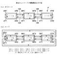
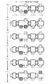
次に、図5に、部分ネットワーク上での音響信号の伝送時における、図3に示したTLフレームの伝送状況を示す。
ここでは、ノードAからノードDまでの4つのノードをカスケード接続した部分ネットワークを考える。そして、この部分ネットワーク内の各ノードにTLフレーム100を循環させる場合、いずれか1つのノードを部分マスタと定め、そのノードのみが新たなサンプリング周期のTLフレーム(通し番号の異なるTLフレーム)の生成を行い、サンプリング周期毎に生成されたTLフレームを次のノードへ送信する。部分マスタ以外のノードはスレーブノードであり、それぞれ前のノードからTLフレームを受信し、次のノードへ送信する転送処理を行う。Next, FIG. 5 shows a transmission state of the TL frame shown in FIG. 3 at the time of transmission of the acoustic signal on the partial network.
Here, consider a partial network in which four nodes from node A to node D are cascade-connected. When the TL frame 100 is circulated to each node in the partial network, any one node is determined as a partial master, and only that node generates a TL frame (TL frame having a different serial number) with a new sampling period. And transmit the TL frame generated every sampling period to the next node. Nodes other than the partial master are slave nodes, each of which performs a transfer process of receiving a TL frame from the previous node and transmitting it to the next node.
そして、部分マスタであるノードBが最初に図で右向きに、ワードクロックのタイミングに合わせて、ノードCに向かってTLフレームを送信すると、そのTLフレームは、破線で示すように、ノードB→C→D→C→B→A→Bの順で伝送され、ノードBに戻ってくる。この伝送の際、各ノードは、TLフレームを受信してから送信するまでに、他のノードから受信すべき波形データや制御データをTLフレームから読み取り、また他のノードに送信すべき波形データや制御データをTLフレームに書き込む。 Then, when the node B which is the partial master first transmits a TL frame toward the node C in the right direction in the drawing in accordance with the timing of the word clock, the TL frame is represented by a node B → C as indicated by a broken line. The data is transmitted in the order of D → C → B → A → B and returns to the node B. During this transmission, each node reads the waveform data and control data to be received from other nodes from the TL frame and receives the waveform data to be transmitted to the other nodes until it is transmitted after receiving the TL frame. Write control data to the TL frame.
そして、部分マスタは、TLフレームが伝送路を1周して戻ってくると、そのTLフレームの管理データを書き換えて後のサンプル周期のTLフレームを生成し、適当なサンプル周期での送信に供する。またこのとき、部分マスタも他のノードと同様にTLフレームに対してデータの読み書きを行う。 Then, when the TL frame returns around the transmission line once, the partial master rewrites the management data of the TL frame to generate a TL frame having a later sample period, and uses it for transmission at an appropriate sample period. . At this time, the partial master also reads / writes data from / to the TL frame in the same manner as other nodes.
以上を繰り返すことにより、1サンプリング周期につき1つのTLフレームに、(a)から(e)に時系列的に示すように、各ノードを循環させることができる。これらの図において、黒塗りの矢印はTLフレームの先頭を、黒丸はTLフレームの末端を示す。線の矢印は、TLフレームの切れ目を分かり易くするために記載したものである。 By repeating the above, each node can be circulated in one TL frame per sampling period as shown in time series from (a) to (e). In these drawings, the black arrow indicates the beginning of the TL frame, and the black circle indicates the end of the TL frame. Line arrows are described for easy understanding of TL frame breaks.
なお、ループ接続を行い、部分ネットワーク内に伝送路を2本形成する場合には、図2からわかるように、部分マスタであるノードBが生成して図で右向きに送信したTLフレームを、ノードB→C→D→A→Bの順で伝送する伝送路と、ノードBが生成して図で左向きに送信したTLフレームを、ノードB→A→D→C→Bの順で伝送する伝送路とができることになる。そしてこの場合、TLフレームが伝送路を1周する間に全てのノードを1回ずつ通過することになるため、各ノードは、その通過の際にデータの読み書きを行う。 In addition, when loop connection is performed and two transmission lines are formed in the partial network, as can be seen from FIG. 2, the TL frame generated by the node B as the partial master and transmitted to the right in the figure is Transmission path for transmitting in the order of B → C → D → A → B, and transmission for transmitting the TL frame generated by the node B and transmitted leftward in the figure in the order of the node B → A → D → C → B You can make a road. In this case, since the TL frame passes through all the nodes once while making one round of the transmission path, each node reads and writes data during the passage.
1.5 システムを構成する各装置のハードウェア構成及び基本動作
次に、以上説明してきたようなTLフレームの伝送を行うためのハードウェア及びその動作について説明する。
図6に、上述のオーディオネットワークシステムSを構成する各ノードとなる音響信号処理装置のハードウェア構成を示す。1.5 Hardware Configuration and Basic Operation of Each Device Constituting System Next, hardware for transmitting a TL frame as described above and its operation will be described.
FIG. 6 shows a hardware configuration of an acoustic signal processing device that is each node constituting the audio network system S described above.
図6に示すように、この音響信号処理装置10は、CPU201,フラッシュメモリ202,RAM203,外部機器I/F(インタフェース)204,表示器205,操作子206を備え、これらがシステムバス207により接続されている。また、外部機器I/F204とシステムバス207とに接続するカードI/O(入出力部)210も備えている。 As shown in FIG. 6, the acoustic
そして、CPU201は、この音響信号処理装置10の動作を統括制御する制御手段であり、フラッシュメモリ202に記憶された所要の制御プログラムを実行することにより、表示器205における表示を制御したり、操作子206の操作を検出してその操作に従ってパラメータの値の設定/変更や各部の動作を制御したり、コマンドをカードI/O210を介して他の音響信号処理装置に送信したり、カードI/O210を介して他の音響信号処理装置から受信したコマンドに従った処理を行ったりする。 The
フラッシュメモリ202は、CPU201が実行する制御プログラムを始め、電源を切っても残しておくべきデータを記憶する書き換え可能な不揮発性記憶手段である。
RAM203は、一時的に記憶すべきデータを記憶したり、CPU201のワークメモリとして使用したりする記憶手段である。The
The RAM 203 is a storage unit that stores data to be temporarily stored or used as a work memory for the
外部機器I/F204は、種々の外部機器を接続し入出力を行うためのインタフェースであり、例えば外部のディスプレイ、マウス、文字入力用のキーボード、操作パネル、PC等を接続するためのインタフェースが用意される。PCは、CPU、メモリ、ハードディスク、ディスプレイ、キーボード、マウス、各種インタフェース、等を備え、Windows(商標)等のオペレーティングシステム(OS)が走る、通常のパーソナルコンピュータである。ユーザは、そのOSの元で、所望のアプリケーションソフトを起動して、PCを使用する。 The external device I /
外部機器I/F204は、カードI/O210のオーディオバス217にも接続しており、オーディオバス217を流れる波形データを外部装置に送信したり、外部装置から受信した波形データをオーディオバス217に入力したりすることができる。この外部機器I/F204は、イーサネット、USB、IEEE1394等のいずれのインタフェースであってもよい。 The external device I /
表示器205は、CPU201による制御に従って種々の情報を表示する表示手段であり、例えば、液晶ディスプレイ(LCD)や発光ダイオード(LED)によって構成することができる。
操作子206は、音響信号処理装置10に対する操作を受け付けるためのものであり、種々のキー、ボタン、ダイヤル、スライダ等によって構成することができる。The
The
これらの表示器205及び操作子206は、例えば音響信号処理装置10をコンソールとして構成する場合には、多数のchについて信号処理パラメータやパッチの設定を受け付けるための大型のディスプレイや多数のボタン、スイッチ、電動フェーダ等を設け、入出力装置として構成する場合には電源及びモード設定のための簡単なランプやボタンを設ける等、装置の機能に応じて大きく構成が異なるものである。 For example, when the acoustic
また、カードI/O210は、オーディオバス217と制御バス218を備え、これらのバスに種々のカードモジュールを装着することにより、音響信号処理装置10に対する音響信号及び制御信号の入出力及びその処理を行うことができるようにするためのインタフェースである。ここに装着される各カードモジュールは、オーディオバス217を介して相互に波形データを送受信すると共に、制御バス218を介してCPU201との間で制御信号を送受信し、CPU201の制御を受ける。 The card I / O 210 includes an
オーディオバス217は、任意のカードから任意のカードへ、複数チャンネルの波形データをサンプリング周期に基づくタイミングで各1サンプルずつ時分割伝送する音響信号伝送用ローカルバスである。接続された複数カードの何れか1つがマスタとなり、当該カードが生成し供給するワードクロックに基づいてオーディオバス217の時分割伝送の基準タイミングを制御する。その他の各カードはスレーブとなり、その基準タイミングに基づいて各カードのワードクロックを生成する。 The
図6には、カードI/O210にDSP(デジタル・シグナル・プロセッサ)カード211,212,アナログ入力カード213,アナログ出力カード214,ネットワークI/Fカード215を装着した例を示している。
カードI/O210に装着される各種カードは、そのカードの機能に応じた処理、すなわち、波形データの外部からの入力、波形データの外部への出力、波形データの信号処理、波形データの部分ネットワークへの送受信等を、それぞれ、ワードクロック(波形データのサンプリング周期)に同期したタイミングで実行する。FIG. 6 shows an example in which DSP (digital signal processor)
Various cards attached to the card I / O 210 perform processing according to the function of the card, that is, input of waveform data from the outside, output of waveform data to the outside, signal processing of waveform data, partial network of waveform data Transmission / reception, etc. are executed at timing synchronized with the word clock (waveform data sampling cycle).
また、これらのカードのうちネットワークI/Fカード215が、送信I/Fと受信I/Fを2組備え、図2乃至図4を用いて説明した部分ネットワークPにおけるTLフレーム100の伝送と、TLフレーム100に対する波形データや制御データ等の読み書きとを行う機能を有する。これらの機能を実現するために必要なネットワークI/Fカード215の構成の詳細については、特開2009−94589号公報を参照されたい。 Of these cards, the network I /
そして、ネットワークI/Fカード215以外のカードは、音響信号処理、アナログ信号の入出力などの機能を担うものであるが、音響信号処理装置10に持たせたい機能に応じて任意に選択して装着することができる。さらに、ここで挙げたもの以外でも、その他カード216として、デジタル入出力、音源、レコーダ、エフェクタ等の、種々のカードモジュールを装着可能とすることが考えられる。 Cards other than the network I /
2 オーディオネットワークシステムにおける伝送路の形成手順
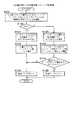
次に、図7乃至図9に、オーディオネットワークシステムS及びそのシステムに属するデバイスを通るTLフレームの伝送路を形成する際の、ユーザによる作業及びそれに応じた各デバイスの動作手順を示す。これらの図に示すのは、各デバイスが物理的に接続されていない状態から伝送路を形成する場合の手順である。2 Procedure for forming transmission path in audio network system Next, FIG. 7 to FIG. 9 show the work performed by the user when forming the transmission path of the TL frame passing through the audio network system S and the devices belonging to the system, and correspondingly. The operation procedure of each device is shown. These figures show the procedure for forming a transmission line from a state in which each device is not physically connected.
図1に示したオーディオネットワークシステムSを形成する場合、ユーザはまず、第1部分ネットワークS1を形成させる2以上のデバイスを、カスケード状又はループ状に接続する(S11)。このとき、デバイスの中の少なくとも1つは、ブリッジデバイスになるデバイスである必要がある。また、ここでいう「接続」には、既に電源が入っているデバイスを通信ケーブルで繋ぐことと、既に通信ケーブルで繋がれているデバイスの電源を入れることと、どちらもなされていないデバイスを通信ケーブルで繋いだ上で電源を入れることとのいずれも含む。 When the audio network system S shown in FIG. 1 is formed, the user first connects two or more devices forming the first partial network S1 in a cascade or loop (S11). At this time, at least one of the devices needs to be a device that becomes a bridge device. In addition, “connection” here refers to connecting a device that is already turned on with a communication cable, turning on a device that is already connected with a communication cable, and communicating with a device that is neither connected. This includes both turning on the power after connecting with a cable.
そして、この接続がなされると、接続されたデバイスは、自動的に互いのデバイスの存在及びその接続のトポロジー(カスケードかループか、及び各デバイスの接続順)を確認した上で、そのトポロジーに応じて、接続されたデバイスの間を循環する、図2に示したようなTLフレームの伝送路を形成し、その伝送路に沿ったTLフレームの伝送を開始する(S21)。 When this connection is made, the connected devices automatically check the existence of each other's devices and the topology of the connection (cascade or loop, and the connection order of each device), and then change to that topology. In response, a TL frame transmission path as shown in FIG. 2 that circulates between the connected devices is formed, and transmission of the TL frame along the transmission path is started (S21).
ただし、この段階ではまだTLフレームに対する音響信号の読み書きは行わず、TLフレーム100のうちITLフレーム領域107や制御データ領域104を用いて、デバイス間で制御データの伝送を行うモード(TTLモード)で動作する。また、TLフレームを生成するノードとなる仮の部分マスタは、デバイス間でネゴシエーションして適当なアルゴリズムで定める。
この際の伝送路の形成手順については、例えば特開2009−94589号公報に記載のものを採用することができる。However, at this stage, the acoustic signal is not yet read from or written into the TL frame, and the control data is transmitted between the devices using the
As a procedure for forming the transmission line at this time, for example, the one described in JP 2009-94589 A can be adopted.
また、ユーザは、ステップS11の後、第1部分ネットワークS1における部分マスタを指定する(S12)。この部分マスタとなったデバイスは、オーディオネットワークシステムS全体のワードクロック源となる。また、この指定は、ステップS21の完了後に行うことが好ましいが、これは必須ではない。 Further, after step S11, the user designates a partial master in the first partial network S1 (S12). The device serving as the partial master serves as a word clock source for the entire audio network system S. In addition, this designation is preferably performed after step S21 is completed, but this is not essential.
そして、ステップS12の指定がなされると、TTLモードで動作中の各デバイスは、ステップS12で指定されたデバイスを部分マスタとして、ステップS11で接続された各デバイスの間を循環するTLフレームの伝送路を再構築し、今度はTLフレームに対する音響信号の読み書きが可能なモード(RTLモード)でTLフレームの伝送を開始し、第1部分ネットワークS1としての動作を開始する(S31)。 When the designation in step S12 is made, each device operating in the TTL mode transmits a TL frame that circulates between the devices connected in step S11 using the device designated in step S12 as a partial master. The road is reconstructed, and this time, transmission of the TL frame is started in a mode (RTL mode) in which an acoustic signal can be read from and written to the TL frame, and the operation as the first partial network S1 is started (S31).
その後、第1部分ネットワークS1の各デバイスは、自身が要求する信号伝送ch数をステップS12で指定された部分マスタ(自身が属する部分ネットワークの部分マスタ)に通知する(S32)。ここで通知するch数は、デバイスがTLフレーム100に対して何chの音響信号を書き込むかを示すものである。また、デバイスが要求する信号伝送ch数は、予め、ユーザにより各デバイス毎に設定されている。 Thereafter, each device of the first partial network S1 notifies the number of signal transmission channels requested by itself to the partial master designated in step S12 (the partial master of the partial network to which it belongs) (S32). The number of channels notified here indicates how many sound signals are written to the TL frame 100 by the device. Further, the number of signal transmission channels requested by the device is set in advance for each device by the user.
なお、ステップS32の通知は、TLフレーム100の制御データ領域104に記載する部分マスタ宛てのイーサネットフレームにより行ったり、ITLフレーム領域107に記載するITLフレームを、隣接ノードに順次中継させながら部分マスタまで届けることにより行ったりすることができる。以降に述べる、部分マスタと各デバイスの間の通信についても同様である。 Note that the notification in step S32 is performed by an Ethernet frame addressed to the partial master described in the
一方、部分マスタは、ステップS32の通知を受けると、その通知に応じて通知元のデバイスにTLフレーム100における信号伝送chを割り当て、割り当てを受けたデバイスは、その割り当てられた信号伝送chを確保する(S33)。どのデバイスにどのchを割り当てても問題ないため、割り当てには、先着順で先頭から割り当てる等、任意のアルゴリズムを採用可能である。 On the other hand, upon receiving the notification in step S32, the partial master allocates the signal transmission channel in the TL frame 100 to the notification source device in response to the notification, and the allocated device secures the allocated signal transmission channel. (S33). Since any channel can be assigned to any device, any algorithm can be used for assignment, such as assignment from the top in the order of arrival.
また、部分マスタは、ステップS33で複数の各デバイスにどの信号伝送chを割り当てたかを示す割り当て情報を、第1部分ネットワークS1(自身が部分マスタを務める部分ネットワーク)の各デバイスに通知する(S34)。各デバイスは、その割り当て情報を参照してどの信号伝送chに音響信号を書き込むかを決定するため、この割り当て情報の通知は、新たな割り当てを行う度に、すなわち信号伝送chの割り当てを変更する度に行うことが好ましい。
そして、各デバイスは、ステップS34での通知を受けると、受信した割り当て情報と、設定されているパッチの情報とに基づいて、TLフレームへの音響信号の書き込み及び読み出しを開始する(S35)。以上で、第1部分ネットワークS1において、ノードとなる各デバイスの間で音響信号及び制御信号の送受信が可能な状態となる。In addition, the partial master notifies each device of the first partial network S1 (the partial network in which the partial master serves as the partial master) of allocation information indicating which signal transmission channel is allocated to each of the plurality of devices in step S33 (S34). ). Each device refers to the allocation information to determine which signal transmission channel to write the acoustic signal to. Therefore, the notification of the allocation information changes the allocation of the signal transmission channel every time a new allocation is performed. It is preferable to carry out every time.
Upon receiving the notification in step S34, each device starts writing and reading of the acoustic signal to and from the TL frame based on the received allocation information and the set patch information (S35). As described above, in the first partial network S1, the acoustic signal and the control signal can be transmitted and received between the devices serving as the nodes.
ここでパッチとは、音響信号の送り手(source)から受け手(sink)までの結線のことであり、ユーザはコンソールを操作することにより、所望の送り手から所望の受け手の間のパッチを設定することができる。
例えば、入出力装置またはミキサエンジンの入力ポート(送り手)からミキサエンジンの入力チャンネル(受け手)へのパッチを設定したり、ミキサエンジンの出力チャンネル(送り手)から入出力装置またはミキサエンジンの出力ポート(受け手)へのパッチを設定することができる。さらに、入出力装置の入力ポートから、別の入出力装置の出力ポートにパッチできるようにしてもよい。
1つの結線は、1つの送り手と受け手とを結ぶものであり、パッチの設定は、1又は複数の結線の設定を含む。Here, the patch is a connection from the source to the sink of the acoustic signal, and the user sets a patch between the desired sender and the desired receiver by operating the console. can do.
For example, you can set a patch from the input port of the input / output device or mixer engine (sender) to the input channel (receiver) of the mixer engine, or output the input / output device or mixer engine from the output channel (sender) of the mixer engine You can set a patch to a port (recipient). Further, the input port of the input / output device may be patched to the output port of another input / output device.
One connection connects one sender and receiver, and the patch setting includes one or a plurality of connection settings.
上述したステップS34では、例えば、パッチ設定情報で、第1のデバイスの送り手と第2のデバイスの受け手とが結線されている場合、第1のデバイスは、その第1のデバイスが結線に係る送り手の音響信号をTLフレームの何れの信号伝送chの領域にも書き込んでいなければ、第1のデバイスが確保しておりかつ未使用の信号伝送chの一つをその結線に割り当て、送り手の音響信号を、結線を割り当てた信号伝送chで送信することを自己設定する。
これにより、第1のデバイスは、結線に係る送り手が出力する音響信号(波形データ)を、TLフレームのその結線に割り当てた信号伝送chの領域に書き込むとともに、その音響信号をその信号伝送chで送信していること示す音響信号送信情報を、部分ネットワークの全デバイスに通知する。In step S34 described above, for example, when the sender of the first device and the receiver of the second device are connected in the patch setting information, the first device is related to the connection of the first device. If the sender's acoustic signal is not written in any signal transmission channel area of the TL frame, one of the unused signal transmission channels secured by the first device is assigned to the connection and sent. Self-setting to transmit the hand acoustic signal by the signal transmission channel to which the connection is assigned.
As a result, the first device writes the acoustic signal (waveform data) output by the sender related to the connection in the area of the signal transmission channel assigned to the connection of the TL frame, and writes the acoustic signal to the signal transmission channel. The sound signal transmission information indicating that it is transmitting is notified to all devices in the partial network.
また、上記第2のデバイスの送り手と上記第1のデバイスの受け手とが結線されている場合は、その第2のデバイスから受け取った一連の音響信号送信情報に基づいて、第2のデバイスの送り手の音響信号が書き込まれているTLフレームの信号伝送chを見つけ出し、その信号伝送chの音響信号を受信して結線に係る受け手へ入力することを自己設定する。これにより、第1のデバイスは、TLフレームの音響信号送信情報が示す信号伝送chの領域から音響信号を読み出して、結線に係る受け手に供給する。」 In addition, when the sender of the second device and the receiver of the first device are connected, based on the series of acoustic signal transmission information received from the second device, the second device It finds a signal transmission channel of the TL frame in which the acoustic signal of the sender is written, and receives the acoustic signal of the signal transmission channel and inputs it to the receiver related to the connection. As a result, the first device reads the acoustic signal from the area of the signal transmission channel indicated by the acoustic signal transmission information of the TL frame and supplies the acoustic signal to the receiver related to the connection. "
次に、手順は図8に示す部分に進み、ユーザは、第2部分ネットワークS2を形成させるデバイスを、第1部分ネットワークS1のブリッジデバイスとカスケード状又はループ状に接続する(S13)。この際には、ブリッジデバイスの、ステップS11での接続には用いていないネットワークI/Fカードに対して接続を行う。
そして、この接続がなされると、接続されたデバイスは、ステップS21の場合と同様に、接続されたデバイスの間を循環するTLフレームの伝送路を形成し、TTLモードでその伝送路に沿ったTLフレームの伝送を開始する(S41)。Next, the procedure proceeds to the part shown in FIG. 8, and the user connects the device that forms the second partial network S2 with the bridge device of the first partial network S1 in a cascade or loop form (S13). At this time, the bridge device is connected to the network I / F card that is not used for the connection in step S11.
When this connection is made, the connected device forms a TL frame transmission path that circulates between the connected devices in the TTL mode, as in step S21. Transmission of the TL frame is started (S41).
また、ユーザは、ステップS13の後、第2部分ネットワークS2における部分マスタを、ブリッジデバイスに設定する(S14)。この設定は、ブリッジデバイスを第2部分ネットワークS2のワードクロック源に設定することを意味する。また、ステップS41の後、ブリッジデバイスが自動的に部分マスタとしての機能を開始するようにしてもよい。 Further, after step S13, the user sets the partial master in the second partial network S2 as a bridge device (S14). This setting means that the bridge device is set as the word clock source of the second partial network S2. Further, after step S41, the bridge device may automatically start a function as a partial master.
そして、ステップS14の指定がなされると、TTLモードで動作中の、ステップS13で接続された各デバイスは、ステップS14で指定されたブリッジデバイスを部分マスタとして、各デバイスの間を循環するTLフレームの伝送路を再構築し、今度はRTLモードでTLフレームの伝送を開始し、第2部分ネットワークS2としての動作を開始する(S51)。 Then, when the designation in step S14 is made, each device connected in step S13 that is operating in the TTL mode circulates between the devices using the bridge device designated in step S14 as a partial master. This time, the transmission path of the second partial network S2 is started by starting the transmission of the TL frame in the RTL mode (S51).
以下、ステップS32〜S35の場合と同様に、部分マスタが信号伝送chの割り当てや通知を行い、各デバイスは、信号伝送chの割り当て及びパッチの設定内容に従って、TLフレームへの音響信号の書き込み及び読み出しを開始する(S52〜55)。以上で、第2部分ネットワークS2において、ノードとなる各デバイスの間で音響信号及び制御信号の送受信が可能な状態となる。 Thereafter, as in the case of steps S32 to S35, the partial master performs assignment and notification of the signal transmission channel, and each device writes the acoustic signal to the TL frame according to the assignment of the signal transmission channel and the setting contents of the patch. Reading is started (S52 to 55). With the above, in the second partial network S2, the acoustic signal and the control signal can be transmitted and received between the devices serving as the nodes.
次に、手順は図9に示す部分に進み、ユーザは、ブリッジデバイスに対し、そのブリッジデバイスを跨いでの2つの部分ネットワーク間の音響信号の転送を設定する(S15)。すなわち、第1部分ネットワークS1のTLフレームに書き込まれている複数の音響信号(波形データ)の中から1または複数の音響信号を選択し、選択された音響信号の第1部分ネットワークS1から第2部分ネットワークS2への転送を設定したり、逆に、第2部分ネットワークS2のTLフレームに書き込まれている複数の音響信号の中から1または複数の音響信号を選択し、選択された音響信号の第2部分ネットワークS2から第1部分ネットワークへS1の転送を設定する。
ここで、各部分ネットワークのTLフレームに書き込まれている音響信号は、その部分ネットワークの各デバイスから受信する音響信号送信情報により特定される。ユーザは、その特定されコンソールの表示器に表示された音響信号の中から、転送する音響信号を選択する。Next, the procedure proceeds to the portion shown in FIG. 9, and the user sets the transfer of the acoustic signal between the two partial networks across the bridge device to the bridge device (S15). That is, one or a plurality of acoustic signals are selected from a plurality of acoustic signals (waveform data) written in the TL frame of the first partial network S1, and the second acoustic network is selected from the first partial network S1 to the second of the selected acoustic signals. Setting transfer to the partial network S2, or conversely, selecting one or a plurality of acoustic signals from the plurality of acoustic signals written in the TL frame of the second partial network S2, and selecting the selected acoustic signal The transfer of S1 is set from the second partial network S2 to the first partial network.
Here, the acoustic signal written in the TL frame of each partial network is specified by acoustic signal transmission information received from each device of the partial network. The user selects an acoustic signal to be transferred from among the acoustic signals identified and displayed on the display of the console.
そしてこの設定がなされると、設定のあったブリッジデバイスは、設定された転送の各々について、転送先となる部分ネットワークのTLフレームの、そのブリッジデバイスが確保しておりかつ未使用の信号伝送chの1つをその転送に割り当てる(S61)。その後、転送に係る音響信号を、音響信号送信情報により特定される、送信元の部分ネットワークのTLフレームの1の信号伝送chの領域から読み出し、送信先の部分ネットワークのTLフレームの、転送に割り当てた信号伝送chの領域に書き込む転送動作を開始する(S62)。 Then, when this setting is made, the bridge device that has been set, for each of the set transfers, has secured and unused signal transmission channels of the TL frame of the partial network that is the transfer destination for that bridge device. Is assigned to the transfer (S61). Thereafter, the acoustic signal related to the transfer is read from the area of one signal transmission channel of the TL frame of the transmission source partial network specified by the acoustic signal transmission information, and assigned to the transfer of the TL frame of the transmission destination partial network. The transfer operation for writing to the signal transmission channel area is started (S62).
ここで、TLフレームからの音響信号の読み出しは、ブリッジデバイスの2つのネットワークI/Fカードのうちの、転送元の部分ネットワークに属するネットワークI/Fカードが行い、読み出された音響信号は、オーディオバス217を介して他方のネットワークI/Fカードに供給される。そして、TLフレームへの音響信号の書き込みは、転送先の部分ネットワークに属する他方のネットワークI/Fカードにより行われる。 Here, the readout of the acoustic signal from the TL frame is performed by the network I / F card belonging to the transfer source partial network out of the two network I / F cards of the bridge device, and the readout acoustic signal is It is supplied to the other network I / F card via the
そして、転送に係る複数の音響信号について、それらの音響信号を複数の信号伝送chで送信していることを示す音響信号送信情報を、転送先の部分ネットワークの各デバイスに送信する(S63)。送信される音響信号送信情報は、転送される音響信号が、どの部分ネットワークのどのデバイスのどの送り手から出力された音響信号であるかを示す。
これにより、転送先の部分ネットワークの各デバイスは、音響信号送信情報に基づいて、転送元の部分ネットワークの送り手を、先述したパッチの設定における、送り手の候補の1つとしてユーザに提示するようになる。And about the some acoustic signal which concerns on transfer, the acoustic signal transmission information which shows transmitting those acoustic signals by several signal transmission ch is transmitted to each device of the partial network of a transfer destination (S63). The transmitted acoustic signal transmission information indicates that the transmitted acoustic signal is an acoustic signal output from which sender of which device of which partial network.
Thereby, each device of the transfer destination partial network presents the sender of the transfer source partial network to the user as one of the candidates of the sender in the above-described patch setting based on the acoustic signal transmission information. It becomes like this.
転送先の部分ネットワークにおいて、ユーザが、他の部分ネットワークの送り手とその転送先の部分ネットワークの受け手の間のパッチを設定すると、その受け手が所属するデバイスは、転送を行っているブリッジデバイスからの音響信号送信情報に基づいて、自身が所属する転送先の部分ネットワークのTLフレームから、送り手からの音響信号が書き込まれている信号伝送chを見つけ出し、その信号伝送chを受信して受け手へ入力することを自己設定する。これにより、受け手が所属するデバイスは、TLフレームの音響信号送信情報が示す信号伝送chの領域から音響信号を読み出して、受け手に供給する。 When a user sets a patch between a sender of another partial network and a receiver of the partial network of the transfer destination in the transfer destination partial network, the device to which the receiver belongs is transferred from the bridge device performing the transfer. The signal transmission channel in which the acoustic signal from the sender is written is found from the TL frame of the transfer destination partial network to which the user belongs, and the signal transmission channel is received and received by the receiver based on the acoustic signal transmission information. Self-configuring to enter. Thereby, the device to which the receiver belongs reads out the acoustic signal from the area of the signal transmission channel indicated by the acoustic signal transmission information of the TL frame and supplies it to the receiver.
その後、ブリッジデバイスの各ネットワークI/Fが各サンプリング周期においてステップS62で開始した読み出しと書き込みを行うことにより、送信元部分ネットワーク内で伝送していた音響信号を、送信先部分ネットワークに転送し、送信先部分ネットワークに属するデバイスが任意に読み出せる状態にすることができる。
この伝送は、第1部分ネットワークS1から第2部分ネットワークS2に向かう方向と、第2部分ネットワークS2から第1部分ネットワークS1へ向かう方向との双方について任意に設定可能であり、これらの一方のみを行うことも、両方を並行して行うことも可能である。After that, each network I / F of the bridge device performs reading and writing started in step S62 in each sampling period, thereby transferring the acoustic signal transmitted in the transmission source partial network to the transmission destination partial network, A device belonging to the transmission destination partial network can be arbitrarily read.
This transmission can be arbitrarily set for both the direction from the first partial network S1 to the second partial network S2 and the direction from the second partial network S2 to the first partial network S1, and only one of these can be set. Both can be done in parallel.
そして、図示は省略したが、ステップS63の後、ユーザが各デバイスに対し、ブリッジデバイスを跨いで転送されてきた所望の1又は複数の音響信号をTLフレームから読み出して、該デバイスの適当な入力chあるいは出力端子に供給するパッチの設定を行うことにより、実際に送信先部分ネットワークに属するデバイスにその音響信号を読み出させることができる。 Although not shown, after step S63, the user reads out one or more desired acoustic signals transferred across the bridge device to each device from the TL frame, and appropriately inputs the device. By setting the patch to be supplied to the channel or output terminal, it is possible to cause the device actually belonging to the transmission destination partial network to read out the acoustic signal.
3.ワードクロックの伝達制御
ところで、以上説明してきたオーディオネットワークシステムSにおいて、特徴的な点は、あるデバイスをシステム全体のワードクロック源にしてシステムが動作している時に、システム全体のワードクロック源が別のデバイスに変更された場合でも、速やかに変更後のデバイスからシステム内の全デバイスにワードクロックのタイミングを供給できるようにするための、各デバイスの、特にブリッジデバイスの動作である。
そこで、以下この点について説明する。3. By the way, in the audio network system S described above, the characteristic point is that when the system is operating with a certain device as the word clock source for the entire system, the word clock source for the entire system is different. This is the operation of each device, particularly the bridge device, in order to be able to quickly supply word clock timing to all devices in the system from the device after the change even when the device is changed.
Therefore, this point will be described below.
3.1 ワードクロックの生成
まず、オーディオネットワークシステムSを構成する各デバイスにおいてワードクロックがどのように供給されるかについて説明する。
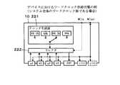
図10に示すのは、システム全体のワードクロック源となる音響信号処理装置10におけるワードクロックの供給状態を模式的に示す図である。3.1 Generation of Word Clock First, how the word clock is supplied in each device constituting the audio network system S will be described.
FIG. 10 is a diagram schematically showing a supply state of the word clock in the acoustic
この図において、クロック生成部221は、所定の発振器の出力信号をPLL(位相ロックループ)回路により分周する等して所望の周波数のクロック信号を生成するクロック生成手段である。ここでは、44.1キロヘルツ、48キロヘルツ、88.2キロヘルツ、96キロヘルツの4つの周波数のクロック信号を生成可能であり、そのいずれかを選択して出力することができる。 In this figure, a
また、WCinは、オーディオネットワークシステムSの外部のクロック供給装置からクロック信号を入力する端子である。WCoutは、オーディオネットワークシステムSの外部の装置に対してクロック信号を出力する端子である。
また、a1〜a4は、カードI/O210に接続されるカードによるデジタルまたはアナログの音声入力端子(入力ポート)または音声出力端子(出力ポート)を示す。DSPは、カードI/O210に接続されるDSPカードを示す。i/o1,i/o2は、同じくネットワークI/Fカードを示す。音響信号処理装置10がブリッジデバイスである場合はネットワークI/Fカードは2枚装着されるが、ブリッジデバイス以外のデバイスであれば1枚のみであり、破線で示したi/o2は存在しない。WCin is a terminal for inputting a clock signal from a clock supply device external to the audio network system S. WCout is a terminal that outputs a clock signal to a device external to the audio network system S.
Further, a1 to a4 indicate digital or analog audio input terminals (input ports) or audio output terminals (output ports) by a card connected to the card I / O 210. DSP indicates a DSP card connected to the card I / O 210. i / o1 and i / o2 indicate network I / F cards. When the acoustic
そして、破線で示す矢印が、ワードクロックの供給源の候補例である。すなわち、候補としては例えば、内部のクロック生成部221により生成したクロック、外部のクロック供給装置から供給されるクロック、あるいはデジタル入力端子に供給されるデジタル音響信号の伝送クロックが挙げられる。いずれも、オーディオネットワークシステムSを構成する他のデバイスの動作に影響されない、独自タイミングのクロックを供給する手段である。 An arrow indicated by a broken line is a candidate example of a word clock supply source. That is, examples of the candidates include a clock generated by the internal
セレクタ222は、これらの候補のいずれかを選択するためのものであり、セレクタ222が選択したクロックが、オーディオネットワークシステムSを構成する各デバイスの動作タイミングの基準となるワードクロックとして用いられ、実線で示すように音響信号処理装置10の各部にも供給される。特に、ネットワークI/Fカードにおいては、ワードクロックのタイミングに同期してTLフレームの送信を行う。
ただし、実線の経路であっても、選択されたワードクロックの供給元への供給は、そのワードクロックを使う目的がないので無意味である。また、同様に、スレーブ動作しているネットワークI/Fカードへの供給も、無意味である。これらの供給を行っても、ワードクロックは何の作用もしない。The
However, even if it is a path | route of a continuous line, supply to the supply source of the selected word clock does not have the purpose which uses the word clock, and is meaningless. Similarly, the supply to the network I / F card operating as a slave is meaningless. Even with these supplies, the word clock has no effect.
なお、このワードクロックの位相をずらして音響信号処理装置10の各部に供給してもよい。例えば、特開2008−72363号公報に記載のように、DSPカードにおいては、ネットワークI/FカードでのTLフレームの送信タイミングの決定に用いる伝送用ワードクロックよりも所定の目標遅延Dtだけ遅延させた信号処理用ワードクロックを用いることが好ましい。 The phase of the word clock may be shifted and supplied to each unit of the acoustic
また、音響信号処理装置10が、図10に示す各部を全て備えている必要はなく、少なくとも、ネットワークI/Fカードに加え、独自タイミングによるワードクロックの供給源(図示したもの以外でもよい)を1つ備えてれば、システム全体のワードクロック源(あるいはブリッジデバイスにおける後述する臨時のワードクロック源)としての機能を果たせる。 Further, the acoustic
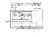
次に、図11に、システム全体のワードクロック源以外のデバイスとなる音響信号処理装置10におけるワードクロックの供給状態を、図10と同様に示す。
この図からわかるように、システム全体のワードクロック源以外のデバイスでは、ワードクロックの供給源は、ネットワークI/Fカードである。すなわち。ネットワークI/FカードにおけるTLフレームの受信タイミングを基準にワードクロックを生成する。Next, FIG. 11 shows the supply state of the word clock in the acoustic
As can be seen from this figure, in a device other than the word clock source of the entire system, the source of the word clock is a network I / F card. That is. A word clock is generated based on the reception timing of the TL frame in the network I / F card.
ワードクロック源のデバイスが送信するTLフレームは、常にほぼ同じ速さで伝送路を循環するから、伝送路上の各デバイスは、ワードクロック源のデバイスにおけるワードクロックと同じ周期でTLフレームを受信する。従って、この受信タイミングをPLL等に入力して周期を整えれば、ワードクロック源のデバイスにおけるものと同じ周期のワードクロックを生成することができる。
つまり、部分ネットワークの各デバイスへは、その部分ネットワークを介して、システム全体のワードクロック源からのワードクロックが伝達されているのである。Since the TL frame transmitted by the word clock source device always circulates in the transmission path at almost the same speed, each device on the transmission path receives the TL frame at the same cycle as the word clock in the word clock source device. Therefore, if this reception timing is input to a PLL or the like to adjust the period, a word clock having the same period as that in the word clock source device can be generated.
That is, the word clock from the word clock source of the entire system is transmitted to each device of the partial network through the partial network.
また、特開2008−72363号公報に記載のように、部分マスタにおけるTLフレームの送受信タイミングや、各デバイスにおけるTLフレームの受信タイミング等に基づいて、部分マスタがTLフレームを送信してから各デバイスがそのTLフレームを受信するまでの時間を求め、その時間を加味して、TLフレームの受信タイミングに基づくワードクロックを適当な時間だけ遅延させることにより、ワードクロック源のデバイスにおける信号処理用ワードクロックと同じ位相の信号処理用ワードクロックを得ることができる。 Further, as described in Japanese Patent Application Laid-Open No. 2008-72363, each device after the partial master transmits the TL frame based on the transmission / reception timing of the TL frame in the partial master, the reception timing of the TL frame in each device, and the like. By obtaining the time until the TL frame is received and taking the time into account, the word clock based on the reception timing of the TL frame is delayed by an appropriate time, whereby the word clock for signal processing in the word clock source device A signal processing word clock having the same phase as the above can be obtained.
また、ブリッジデバイスが、音響信号をブリッジするデバイス(音響信号ブリッジ)としての動作、すなわちそのブリッジデバイスを跨ぐ音響信号の転送を行うためには、自身が接続される2つの部分ネットワークの少なくとも一方では、部分マスタとして動作しなければならない。そして、図11に示すように他方の部分ネットワークでスレーブとして動作している場合、その部分ネットワークにおけるTLフレームの受信タイミングを基準にワードクロックを生成し、その生成したワードクロックに基づき、部分マスタを務める部分ネットワークにおけるTLフレームの送信タイミングを決定する。
このようにして、システム全体のワードクロック源から一方の部分ネットワークを介して伝達されてきたワードクロックが、ブリッジデバイスを跨いで他方の部分ネットワークへ伝達される。In addition, in order for the bridge device to operate as a device that bridges an acoustic signal (acoustic signal bridge), that is, to transfer an acoustic signal across the bridge device, at least one of the two partial networks to which the bridge device is connected is used. Must act as a partial master. Then, when operating as a slave in the other partial network as shown in FIG. 11, a word clock is generated based on the reception timing of the TL frame in the partial network, and the partial master is determined based on the generated word clock. The transmission timing of the TL frame in the serving partial network is determined.
In this way, the word clock transmitted from the word clock source of the entire system via one partial network is transmitted across the bridge device to the other partial network.
なお、この場合、ブリッジデバイスは、TLフレームの受信タイミングを基準に生成したワードクロックを、上記の信号処理用ワードクロックの場合と同様に適当な時間だけ遅延させ、ワードクロック源のデバイスにおける信号伝送用ワードクロックと同じ位相の信号伝送用ワードクロックを生成し、TLフレームの送信タイミングの基準に用いるようにするとよい。
このようにすれば、システム全体のワードクロック源と異なる部分ネットワークに属するデバイスにおいても、システム全体のワードクロック源と同じ部分ネットワークに属するデバイスと同じ手法で、システム全体のワードクロック源のデバイスにおける信号処理用ワードクロックと同じ位相の信号処理用ワードクロックを得ることができる。In this case, the bridge device delays the word clock generated based on the reception timing of the TL frame by an appropriate time as in the case of the signal processing word clock, and transmits the signal in the word clock source device. A signal transmission word clock having the same phase as that of the word clock may be generated and used as a reference for the transmission timing of the TL frame.
In this way, even in a device that belongs to a partial network different from the word clock source of the entire system, the signal in the device of the word clock source of the entire system is used in the same manner as a device that belongs to the same partial network as the word clock source of the entire system. A signal processing word clock having the same phase as the processing word clock can be obtained.
なお、ブリッジデバイスは、自身が接続される2つの部分ネットワークの双方で部分マスタとなっている場合も、音響信号ブリッジとしての動作を行うことができる。この場合には、図10に示したように、セレクタ222が選択した同じワードクロックに基づいて双方の部分ネットワークにおけるTLフレームの送信タイミングを制御することにより、双方の部分ネットワークに同じワードクロックタイミングを伝達することができる。
何れにせよ、2つの部分ネットワークのTLフレームの周期が一致することが、ブリッジデバイスが音響信号ブリッジとして動作するための必要条件である。The bridge device can operate as an acoustic signal bridge even when it is a partial master in both of the two partial networks to which it is connected. In this case, as shown in FIG. 10, by controlling the transmission timing of the TL frame in both partial networks based on the same word clock selected by the
In any case, matching the TL frame periods of the two partial networks is a necessary condition for the bridge device to operate as an acoustic signal bridge.
3.2 部分マスタの設定に応じた動作
次に、部分マスタの設定が行われた場合の処理について説明する。この処理は、図7のステップS12でシステム全体のワードクロック源の設定として行われた場合も、図8のステップS14で部分ネットワークのワードクロック源の設定として行われた場合も、オーディオネットワークシステムSが動作を開始した後で、システム全体のワードクロック源を別のデバイスに変更する設定として行われた場合も、同じものでよい。また、部分ネットワークのワードクロック源を自動的に設定する場合も、同じ処理でよい。3.2 Operation according to Partial Master Setting Next, processing when partial master setting is performed will be described. This processing is performed as the setting of the word clock source of the entire system in step S12 of FIG. 7 or the setting of the word clock source of the partial network in step S14 of FIG. The same can be applied to the case where the setting is made to change the word clock source of the entire system to another device after the operation starts. Further, the same processing may be performed when the word clock source of the partial network is automatically set.
本実施形態においては、部分マスタを設定するためのコマンドとして、動作モード切替(OM)コマンドを用意しており、このコマンドを受け取ったネットワークI/Fカードが、該カードの装着されたデバイスを部分ネットワークにおける部分マスタに設定すると共に、マスタとしての動作を開始する。そして、そのデバイスが独自のタイミングでワードクロックを生成している場合、そのデバイスは同時にシステム全体のワードクロック源ともなる。 In the present embodiment, an operation mode switching (OM) command is prepared as a command for setting a partial master, and the network I / F card that has received this command sets the device with the card attached to the partial master. Set as a partial master in the network and start operation as a master. When the device generates a word clock at a unique timing, the device simultaneously becomes a word clock source for the entire system.
このOMコマンドは、ユーザによる部分マスタの設定操作があった場合に、その設定操作を受け付けたデバイスが生成し、部分マスタに設定された装置の、マスタとしての動作を実行させたいネットワークI/Fカードに宛てて、ITLフレームとして送信する。ネットワークシステムSを構成する装置が自動で生成して送信する場合もある。
いずれにせよ、ITLフレームであるので、コマンドの宛先に関わらず、送信は隣接のデバイスに対してしか行えない。そして、TLフレームの伝送路を形成する際に接続したデバイスの接続トポロジーの情報に基づき、ネットワークI/Fカード215が備える2つの送信I/Fのうち、宛先のデバイスが存在する側の送信I/Fから送信すればよい。This OM command is generated by a device that accepts a setting operation of a partial master by the user, and is a network I / F that is to be operated as a master of a device set as the partial master. It is sent to the card as an ITL frame. In some cases, the devices constituting the network system S automatically generate and transmit.
In any case, since it is an ITL frame, transmission can be performed only to an adjacent device regardless of the destination of the command. Then, based on the connection topology information of the devices connected when forming the transmission path of the TL frame, the transmission I on the side where the destination device exists out of the two transmission I / Fs included in the network I /
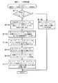
ここで、図12に、各音響信号処理装置10のネットワークI/Fカード215がOMコマンドを受信した場合に、そのネットワークI/Fカード215のCPUが実行する処理のフローチャートを示す。なお、この処理は、ブリッジデバイスのように複数のネットワークI/Fカードを有するデバイスにおいては、ネットワークI/Fカード毎に行う。すなわち、以下の説明における「ネットワークI/Fカード215」とは、OMコマンドを受信したネットワークI/Fカードのことである。 Here, FIG. 12 shows a flowchart of processing executed by the CPU of the network I /
図12の処理において、ネットワークI/Fカード215のCPUはまず、受信したOMコマンドがネットワークI/Fカード215宛てか否か判断する(S111)。そして、自身宛てでなければ、受信したOMコマンドのITLフレームを、そのまま受信した側と反対側に送信して(S118)処理を終了する。OMコマンドが宛先のネットワークI/Fカードに届くまでは、途中の各デバイスのネットワークI/Fカードがこのように順次ITLフレームの伝送を仲介する。 In the processing of FIG. 12, the CPU of the network I /
なお、この仲介が必要なのは、1つの部分ネットワーク内では、TLフレームの巡回が未だ始まっていない場合であって、TLフレームの巡回が始まった後(RTL又はTTL動作中)は、OMコマンドをTLフレームのイーサネット領域で送信することにより、その部分ネットワークの全デバイスに伝達することができるので、同じ部分ネットワーク内での仲介は必要なくなる。また、デバイスがブリッジデバイスである場合は、TLフレームが巡回しているか否かに関わらず、一方の部分ネットワークで受信したOMコマンドを、他方の部分ネットワークに転送する。 Note that this mediation is necessary when TL frame circulation has not yet started in one partial network. After TL frame circulation has started (during RTL or TTL operation), an OM command is sent to the TL command. By transmitting in the Ethernet area of the frame, it can be transmitted to all devices in the partial network, so no intermediary is required in the same partial network. If the device is a bridge device, the OM command received by one partial network is transferred to the other partial network regardless of whether or not the TL frame is circulating.
一方、ステップS111でネットワークI/Fカード215宛てであれば、OMコマンドに対する応答であるOM応答のITLフレームを、OMコマンドを初めに送信した送信元装置を宛先として、その装置が存在する側に対して送信する(S112)。そして、ネットワークI/Fカード215をリセットして、両側でTLフレームの伝送経路を折り返す初期動作モードに戻す(S113)。このことにより、ネットワークI/Fカード215はTTLモード又はRTLモードの伝送経路から一旦離脱することになる。 On the other hand, if it is addressed to the network I /
その後、ネットワークI/Fカード215に、OMコマンドを受信した部分ネットワークにおけるマスタ動作を開始させる(S114)。これは、ネットワークI/Fカード215が装着された音響信号処理装置10がその部分ネットワークにおける部分マスタになったことを意味する。 Thereafter, the network I /
そして、ネットワークI/Fカード215にRTLモードの動作を開始させる(S115)と共に、両側のデバイスに対してリセット指示コマンドのITLフレームを送信する(S116)。さらに、ネットワークI/Fカード215のリセットを行った旨及びネットワークI/Fカード215にマスタ動作を開始させた旨を、データリンク層に当たるネットワークI/Fカード215よりも上位層の処理を行うCPU201に通知して(S117)、処理を終了する。 Then, the network I /
次に、図13に、各音響信号処理装置のネットワークI/Fカード215が図12のステップS116で送信されるSリセット指示コマンドを受信した場合に、そのネットワークI/Fカード215のCPUが実行する処理のフローチャートを示す。この処理も、図12の場合と同様、ネットワークI/Fカード毎に行うものである。
図13の処理において、CPUはまず、図12のステップS113の場合と同様にネットワークI/Fカード215をリセットする(S121)。そして、リセット指示コマンドの送信元に対し、そのコマンドへの応答であるリセット応答のITLフレームを送信する(S122)。Next, in FIG. 13, when the network I /
In the process of FIG. 13, the CPU first resets the network I /
その後、リセット指示コマンドを受信した側と反対側の送信I/Fからリセット指示コマンドのITLフレームを送信する(S123)と共に、ネットワークI/Fカード215のリセットを行った旨を上位層の処理を行うCPU201に通知して(S124)、処理を終了する。
また、ステップS123の処理で送信されたリセット指示コマンドを受信した隣接デバイスのネットワークI/Fカード215においても、そのCPUが同じく図13の処理を行う。そしてこの連鎖は、部分ネットワークの全てのネットワークI/Fカード215がリセットされるまで続く。Thereafter, the ITL frame of the reset instruction command is transmitted from the transmission I / F on the opposite side to the side receiving the reset instruction command (S123), and the upper layer processing is performed to indicate that the network I /
In the network I /
従って、図12の処理を行ったネットワークI/Fカード215が接続される部分ネットワークにおいては、他の全てのデバイスのネットワークI/Fカードが順次リセットされることになる。このことを、部分ネットワークの「リセット」と呼ぶことにする。
そしてその後、又はリセットの連鎖と並行して、図12の処理を行ったネットワークI/Fカード215が装着された音響信号処理装置10を部分マスタとして、RTLモードのTLフレームの伝送経路が再構築され、図7のステップS31乃至S35と同様な手順を経て、再び部分ネットワークを構成する各デバイスの間で音響信号及び制御信号の送受信が可能な状態となる。Accordingly, in the partial network to which the network I /
Then, or in parallel with the reset chain, the transmission path of the TL frame in the RTL mode is reconstructed with the acoustic
なお、一旦オーディオネットワークシステムSが動作を開始した後で図12の処理を実行した場合には、リセットの際も信号伝送chの割り当てやパッチ、およびブリッジデバイスを跨いだ1又は複数の音響信号の転送の設定内容を保持しておき、伝送経路の再構築後に、各デバイスがリセット前と同じ設定内容に従って動作できるようにしてもよい。 Note that when the processing of FIG. 12 is executed after the audio network system S starts operating, the signal transmission channel assignments and patches, and one or a plurality of acoustic signals straddling the bridge device are also reset. The transfer setting contents may be held so that after the transmission path is reconfigured, each device can operate according to the same setting contents as before the reset.
3.3 ブリッジデバイスの動作
次に、上述のOMコマンドによりシステム全体のワードクロック源が別のデバイスに変更された場合でも、速やかに変更後のデバイスからシステム内の各デバイスにワードクロックのタイミングを供給できるようにするために、ブリッジデバイスが実行する処理について説明する。
上述したように、ブリッジデバイスは、自身がブリッジする2つの部分ネットワークのうち一方でスレーブ、他方でマスタとして動作する場合と、2つの部分ネットワークのうち双方でマスタとして動作する場合と、2つのネットワークI/Fの一方のみにより1つの部分ネットワークに接続され、そこでマスタ動作又はスレーブ動作を行う場合とがある。3.3 Operation of Bridge Device Next, even when the word clock source of the entire system is changed to another device by the above OM command, the word clock timing is promptly transmitted from the changed device to each device in the system. A process executed by the bridge device to enable the supply will be described.
As described above, the bridge device operates as a slave in one of the two partial networks that it bridges, and as a master in the other of the two partial networks, and in two networks of the two partial networks. There is a case where only one of the I / Fs is connected to one partial network and performs a master operation or a slave operation there.
これらのいずれの場合についても、各ネットワークI/Fがスレーブとして動作しているかマスタとして動作しているかに応じて、CPU201は、ネットワークI/Fカード215によるTLフレームの伝送の上位層に当たる処理として、図14及び図15のフローチャートに示す処理を、定期的に行う。 In any of these cases, depending on whether each network I / F is operating as a slave or as a master, the
図14に示す処理は、部分ネットワークにおいてスレーブとして動作するネットワークI/Fカードについて行う処理であり、図15に示す処理は、同じくマスタとして動作するネットワークI/Fカードについて行う処理である。どちらの動作もしていない(他のデバイスと接続されておらず、部分ネットワークに属してもいない)ネットワークI/Fカードについては、処理を行う必要はない。 The process shown in FIG. 14 is a process performed on a network I / F card that operates as a slave in a partial network, and the process shown in FIG. 15 is a process performed on a network I / F card that also operates as a master. For network I / F cards that do not perform either operation (not connected to other devices and do not belong to a partial network), there is no need to perform processing.
まず、図14に示す処理において、CPU201は、注目しているスレーブ動作中のネットワークI/Fカード(Xとする。どちらのネットワークI/FカードがXとなるかは、処理の開始時に判断する。図15及び図17においても同じ。)において、TLフレームを継続的に受信できているか否かを確認する(S131)。これは、主に部分ネットワークにリセットがかかっていないことを確認するための処理である。従って、ループ接続の部分ネットワークのうち1箇所の接続が切れてネットワークをカスケード接続に組み換える場合のように、数サンプリング周期程度の受信中断であれば、「継続的に受信」と扱って差し支えない。 First, in the processing shown in FIG. 14, the
そして、継続的に受信できていれば(S132のYES)、ネットワークI/FカードXに関する伝送確認フラグRF(X)に、そのネットワークI/FカードにおけるTLフレームの伝送が正常に行われていることを示す「1」を設定する(S133)。また、ネットワークI/FカードXにおけるTLフレームの受信タイミングを、ブリッジデバイスにおけるワードクロック源として選択する(S134)。既にこの選択がなされていれば、その選択を維持する。
このことにより、マスタ動作をする他方のネットワークI/Fカード(Yとする)が、ブリッジデバイスがスレーブとして動作する部分ネットワークにおけるワードクロックと同期したタイミングでTLフレームを送信し、そのワードクロックのタイミングを、ブリッジデバイスがマスタとして動作する部分ネットワークに伝達することができる。If it is continuously received (YES in S132), transmission of the TL frame in the network I / F card is normally performed in the transmission confirmation flag RF (X) regarding the network I / F card X. “1” indicating this is set (S133). Also, the reception timing of the TL frame in the network I / F card X is selected as the word clock source in the bridge device (S134). If this selection has already been made, the selection is maintained.
As a result, the other network I / F card (Y) performing the master operation transmits a TL frame at a timing synchronized with the word clock in the partial network in which the bridge device operates as a slave, and the timing of the word clock. Can be transmitted to a partial network in which the bridge device operates as a master.
また、CPU201はさらに、他方のネットワークI/FカードYがマスタ動作中であり、かつそのカードYについての伝送確認フラグRF(Y)の値が「1」か否か判断する(S135)。なお、該当のカードから図12のステップS117でなされる通知があり、その後そのカードがリセットされた旨の通知がない場合に、そのカードがマスタ動作中であると判断できる。 Further, the
そして、ステップS135でYESであれば、ステップS132の判断と合わせて、ブリッジデバイスが接続される2つの部分ネットワークの双方において、TLフレームが正常に伝送されており、また上記のワードクロックタイミングの伝達も正しく行われていることがわかる。従って、2つの部分ネットワークにおけるTLフレームの伝送が同期しており、ブリッジデバイスを跨ぐ音響信号の転送を行ってよいと判断できるので、転送フラグBEに、ブリッジデバイスを跨ぐ音響信号の転送を行うことを示す「1」を設定して(S136)、処理を終了する。 If YES in step S135, in conjunction with the determination in step S132, the TL frame is normally transmitted in both of the two partial networks to which the bridge device is connected, and the word clock timing is transmitted. You can see that it is done correctly. Therefore, since it can be determined that the transmission of the TL frame in the two partial networks is synchronized and the acoustic signal across the bridge device may be transferred, the acoustic signal across the bridge device is transferred to the transfer flag BE. Is set to “1” (S136), and the process ends.
一方、ステップS135でNOの場合、2つの部分ネットワークにおけるTLフレームの伝送が同期していないことがわかるので、ブリッジデバイスを跨ぐ音響信号の転送を正常に行えないと判断し、転送フラグBEに、ブリッジデバイスを跨ぐ音響信号の転送を行わないことを示す「0」を設定して(S139)、処理を終了する。 On the other hand, in the case of NO in step S135, it can be seen that the transmission of the TL frame in the two partial networks is not synchronized, so it is determined that the transfer of the acoustic signal across the bridge device cannot be performed normally, and the transfer flag BE is set to “0” indicating that the transfer of the acoustic signal across the bridge device is not performed is set (S139), and the process ends.
また、ステップS102でNOであれば、CPU201は、伝送確認フラグRF(X)に、TLフレームの伝送が正常に行われていないことを示す「0」を設定する(S137)。また、この場合にはもはやネットワークI/FカードXにおけるTLフレームの受信タイミングをワードクロック源として使用できないため、内部クロック(ネットワークI/FカードXにおけるTLフレームの受信タイミング以外の供給元)を、ブリッジデバイスにおけるワードクロック源として選択する(S138)。既にこの選択がなされていれば、その選択を維持する。
そしてこの場合も、2つの部分ネットワークにおけるTLフレームの伝送が同期していない(ネットワークI/FカードXにおいてTLフレームの伝送が行われていないため)ことがわかるので、転送フラグBEに、部分ネットワークを音声伝送を行わないことを示す「0」を設定して(S136)、処理を終了する。If NO in step S102, the
Also in this case, it can be seen that the transmission of the TL frame in the two partial networks is not synchronized (because the transmission of the TL frame is not performed in the network I / F card X). Is set to “0” indicating that voice transmission is not performed (S136), and the process ends.
また、図15に示す処理において、CPU201は、注目しているスレーブ動作中のネットワークI/Fカード(Xとする)において、図14のステップS131の場合と同様、TLフレームを継続的に受信できているか否かを確認する(S151)。
そして、継続的に受信できていれば(S152のYES)、ネットワークI/FカードXに関する伝送確認フラグRF(X)に、TLフレームの伝送が正常に行われていることを示す「1」を設定する(S153)。Further, in the processing shown in FIG. 15, the
If it is continuously received (YES in S152), the transmission confirmation flag RF (X) related to the network I / F card X is set to “1” indicating that the TL frame is normally transmitted. Setting is made (S153).
また、CPU201はさらに、他方のネットワークI/FカードYについての伝送確認フラグRF(Y)の値が「1」か否か判断する(S154)。これがYESであれば、ステップS152の判断と合わせて、ブリッジデバイスが接続される2つの部分ネットワークの双方において、TLフレームが正常に伝送されており、また上記のワードクロックタイミングの伝送も正しく行われていることがわかる(この条件下では図14のステップS135の判断はYESになる)。従って、2つの部分ネットワークにおけるTLフレームの伝送が同期しており、ブリッジデバイスを跨ぐ音響信号の転送を行ってよいと判断できるので、転送フラグBEに「1」を設定して(S155)、処理を終了する。 The
一方、ステップS154でNOの場合、2つの部分ネットワークにおけるTLフレームの伝送が同期していないことがわかるので、ブリッジデバイスを跨ぐ音響信号の転送を正常に行えないと判断し、転送フラグBEに「0」を設定して(S157)、処理を終了する。
また、ステップS152でNOであれば、CPU201は、伝送確認フラグRF(X)に、TLフレームの伝送が正常に行われていないことを示す「0」を設定する(S156)。そしてこの場合も、2つの部分ネットワークにおけるTLフレームの伝送が同期していない(ネットワークI/FカードXにおいてTLフレームの伝送が行われていないため)ことがわかるので、転送フラグBEに「0」を設定して(S157)、処理を終了する。On the other hand, if NO in step S154, it can be seen that the transmission of the TL frame in the two partial networks is not synchronized. Therefore, it is determined that the transfer of the acoustic signal across the bridge device cannot be performed normally, and the transfer flag BE is set to “ “0” is set (S157), and the process is terminated.
If NO in step S152, the
なお、ブリッジデバイスにおけるワードクロック源は、内部クロックあるいは、スレーブ動作するネットワークI/FカードにおけるTLフレームの受信タイミングであるので、マスタ動作するネットワークI/FカードにおけるTLフレームの受信がなくなっても、ワードクロック源に特に影響はない。従って、図15の処理には、ワードクロック源を選択する処理は含まれていない。
以上の図14及び図15の処理により、CPU201は、各ネットワークI/Fが属する部分ネットワークの状況に応じて、ネットワークI/F毎の伝送確認フラグRF及び、転送フラグBEの値を設定することができる。Since the word clock source in the bridge device is the internal clock or the reception timing of the TL frame in the network I / F card that operates as a slave, even if the reception of the TL frame in the network I / F card that operates as a master is stopped, The word clock source is not particularly affected. Therefore, the process of FIG. 15 does not include the process of selecting the word clock source.
14 and 15, the
次に、図16に、ブリッジデバイスのCPU201が定期的に実行する、ブリッジデバイスを跨ぐ音響信号の転送の制御に関する処理のフローチャートを示す。
この処理において、CPU201は、転送フラグBEの値を参照し(S161)、これが「1」であればブリッジデバイスを跨ぐ音響信号の転送動作の実行を2つのネットワークI/Fカードに指示し(S162)、「0」であればブリッジデバイスを跨ぐ音響信号の転送動作の停止を2つのネットワークI/Fカードに指示する(S163)。Next, FIG. 16 shows a flowchart of processing relating to control of transfer of acoustic signals across the bridge device, which is periodically executed by the
In this process, the
なお、ステップS162での開始の指示に応じて、2つのネットワークI/Fカードは、上述したような転送処理を開始する。また、ステップS163での停止の指示に応じて、各ネットワークI/Fカードは、設定されている転送のうちの、そのネットワークカードI/Fカードの所属する部分ネットワークが転送先となる転送に関して、TLフレームの信号伝送chへの音響信号の書き込みを停止するとともに、その音響信号のその信号伝送chでの送信が停止されたことを示す音響信号送信情報を、所属する部分ネットワークの全デバイスに通知する。送信が停止された信号伝送chの音響信号を受信しているデバイスがあった場合、そのデバイスは、通知された音響信号送信情報に応じて、送信が停止された信号伝送chの音響信号の受信を停止する。
以上の処理により、2つの部分ネットワークにおけるTLフレームの伝送が同期していることを条件に、ブリッジデバイスを跨ぐ音響信号の転送を行うことができる。In response to the start instruction in step S162, the two network I / F cards start the transfer process as described above. Further, in response to the stop instruction in step S163, each network I / F card is related to the transfer in which the partial network to which the network card I / F card belongs is the transfer destination among the set transfers. The writing of the acoustic signal to the signal transmission channel of the TL frame is stopped, and the acoustic signal transmission information indicating that the transmission of the acoustic signal on the signal transmission channel is stopped is notified to all the devices in the subnetwork to which it belongs. To do. When there is a device that has received the acoustic signal of the signal transmission channel whose transmission has been stopped, the device receives the acoustic signal of the signal transmission channel whose transmission has been stopped according to the notified acoustic signal transmission information. To stop.
With the above processing, it is possible to transfer the acoustic signal across the bridge device on condition that the transmission of the TL frame in the two partial networks is synchronized.
次に、図17に、ブリッジデバイスのCPU201がネットワークI/Fカードからリセットの通知を受けた場合に実行する処理のフローチャートを示す。
CPU201は、いずれかのネットワークI/Fカード(Xとする)から、図12のステップS117又は図13のステップS124の処理によるネットワークI/Fカードのリセットを行った旨の通知を受けると、図17に示す処理を開始する。Next, FIG. 17 shows a flowchart of processing executed when the
When the
この処理において、CPU201はまず、Xでない方のネットワークI/Fカード(Yとする)が他の機器と接続されているか、すなわち部分ネットワークに属しているか否か判断する(S171)。ここでNOであれば、ブリッジデバイスを跨ぐワードクロックタイミングの伝達について考慮する必要がないため、そのまま処理を終了する。 In this process, the
しかし、YESであれば、ワードクロックタイミングの伝達について考慮すべく、X,Y双方のネットワークI/Fについて、伝送確認フラグRFが「1」になるまで待機する(S172)。ネットワークI/FカードXがリセットされた場合、そのカードXがスレーブ動作中であったかマスタ動作中であったかに応じて図14のステップS137又は図15のステップS156で伝送確認フラグRF(X)が「0」になっているはずである。そこで、リセット後に部分ネットワークにおけるTLフレームの伝送路が再構築されてTLフレームの伝送が再開され、RF(X)が「1」になるのを待つのである。両方のネットワークI/Fカードがほぼ同時にリセットされることもあり得るが、この場合には双方の部分ネットワークにおけるTLフレームの伝送が再開されるのを待つことになる。 However, if YES, in order to consider the transmission of the word clock timing, it waits until the transmission confirmation flag RF becomes “1” for both the X and Y network I / Fs (S172). When the network I / F card X is reset, the transmission confirmation flag RF (X) is set to “in step S137 of FIG. 14 or step S156 of FIG. 15 according to whether the card X is in slave operation or master operation. It should be “0”. Therefore, after resetting, the transmission path of the TL frame in the partial network is reconstructed, the transmission of the TL frame is resumed, and the process waits until RF (X) becomes “1”. It is possible that both network I / F cards are reset almost simultaneously, but in this case, the transmission of TL frames in both partial networks is waited for to resume.
そして、CPU201は、TLフレームの伝送が再開された状態で、ネットワークI/FカードX,Yの少なくとも一方がマスタ動作を行っていれば(S173のYES)、ワードクロックタイミングの伝達が正常に行われていると判断し、そのまま処理を終了する。
ネットワークI/FカードXがスレーブ動作を行っている場合、すなわちカードXの属する部分ネットワークにシステム全体のワードクロック源がある場合、定常状態であれば、他方のネットワークI/FカードYはマスタ動作を続けているはずである。従って、カードXがリセットされた後、スレーブ動作とマスタ動作のいずれを行うことになったとしても、ステップS173の判断はYESとなる。そしてこの場合、ワードクロックのタイミングの伝達は、リセット発生前と同じように継続される。If at least one of the network I / F cards X and Y is performing the master operation in the state where the transmission of the TL frame is resumed (YES in S173), the
When the network I / F card X performs a slave operation, that is, when the word clock source of the entire system is in the partial network to which the card X belongs, the other network I / F card Y operates as a master in the steady state. Should continue. Accordingly, whether the slave operation or the master operation is performed after the card X is reset, the determination in step S173 is YES. In this case, the transmission of the timing of the word clock is continued as before the occurrence of the reset.
しかし、ステップS173でネットワークI/FカードX,Yの双方がスレーブ動作であった場合には、このままではブリッジデバイスを跨ぐワードクロックタイミングの伝達が行えない。そこで、ネットワークI/FカードYを、該カードYが接続された部分ネットワークにおける部分マスタとして指定するOMコマンドを発生させ(S174)、処理を終了する。 However, if both the network I / F cards X and Y are in slave operation in step S173, the word clock timing across the bridge device cannot be transmitted as it is. Therefore, an OM command for designating the network I / F card Y as a partial master in the partial network to which the card Y is connected is generated (S174), and the process ends.
このような状況は、ネットワークI/FカードXのみがマスタ動作を行い、ネットワークI/FカードYがスレーブ動作を行っている状態で、カードXが属する部分ネットワークの他のデバイスが部分マスタとなった場合に起こる。この場合、カードXは、部分マスタが送出するTLフレームの継続的な受信を開始するとスレーブ動作を開始するので、ネットワークI/FカードX,Yの双方がスレーブ動作をすることになるためである。 In such a situation, only the network I / F card X performs a master operation, and the network I / F card Y performs a slave operation, and another device in the partial network to which the card X belongs becomes a partial master. Happens when. In this case, since the card X starts the slave operation when it starts to continuously receive the TL frame transmitted from the partial master, both the network I / F cards X and Y perform the slave operation. .
そしてこの場合、それまでスレーブ動作を行っていたネットワークI/FカードYはこのOMコマンドに応じて図12の処理を実行し、接続されていた部分ネットワークをリセットしてマスタ動作を開始することになる。そしてその後、ネットワークI/FカードXが属する部分ネットワークからネットワークI/FカードYが属する部分ネットワークへ、ワードクロックのタイミングを伝達できるようになる。 In this case, the network I / F card Y that has been performing the slave operation until then executes the process of FIG. 12 in response to the OM command, resets the connected partial network, and starts the master operation. Become. After that, the timing of the word clock can be transmitted from the partial network to which the network I / F card X belongs to the partial network to which the network I / F card Y belongs.
なおこの場合、ワードクロックの伝達方向は、ネットワークI/FカードXのリセット発生前とは逆向きとなる。
また、図12の処理にもリセットが含まれているため、CPU201は、そのリセットに応じて、再度図17の処理を、今度は前回の処理でネットワークI/FカードYであったカードをネットワークI/FカードXとして実行することになる。そしてこの処理においては、ステップS173の判断はYESとなり、それ以上のOMコマンドは発生しない。In this case, the transmission direction of the word clock is opposite to that before the network I / F card X is reset.
Also, since the process of FIG. 12 includes a reset, the
以上の処理により、ブリッジデバイスは、ワードクロック源となるデバイスが、自身の属する一方の部分ネットワークから他方の部分ネットワークへ移った場合でも、それに応じてブリッジデバイスを跨ぐワードクロックタイミングの伝達方向を適切に変更し、伝達を継続することができる。 As a result of the above processing, even when the device that becomes the word clock source moves from one partial network to which the bridge device belongs to the other partial network, the transmission direction of the word clock timing across the bridge device is appropriately set accordingly. And can continue to communicate.
3.4 ワードクロック源変更時の動作の具体例
次に、オーディオネットワークシステムにおいてシステム全体のワードクロック源が変更された場合の、以上説明してきた処理によるブリッジデバイス及びシステム全体の挙動について、図18及び図19を用いて説明する。
なお、ここでの説明には、図1に示したものよりも複雑な、4つの部分ネットワーク(ここではリング1〜4と称する)からなるオーディオネットワークシステムを例にとって説明する。3.4 Specific Example of Operation when Word Clock Source is Changed Next, the behavior of the bridge device and the entire system by the processing described above when the word clock source of the entire system is changed in the audio network system will be described with reference to FIG. And it demonstrates using FIG.
In the description here, an audio network system composed of four partial networks (herein referred to as
図18(a)に示すように、このオーディオネットワークシステムは、「1−1」〜「4−1」の10台のデバイスを接続して構成したものであり、これらのうち、2つのリングに接続されている「1−1」、「1−3」及び「2−1」のデバイスが、ブリッジデバイスである。そして、このブリッジデバイスのボックスに示した矢印は、ワードクロックタイミングの伝達方向を示す。矢印の根本側のリングが伝達元、先端側のリングが伝達先である。 As shown in FIG. 18 (a), this audio network system is configured by connecting 10 devices "1-1" to "4-1". The connected devices “1-1”, “1-3”, and “2-1” are bridge devices. An arrow shown in the box of the bridge device indicates a transmission direction of the word clock timing. The ring on the base side of the arrow is the transmission source, and the ring on the tip side is the transmission destination.
また、太線で示すデバイスが、各リングの部分マスタである。ハッチングを付したデバイスが、システム全体のワードクロック源となっているデバイスである。太字で示すリングは、TLフレームの定期的な伝送が行われているリング、細線で示すリングは、リセット後、TLフレームの伝送経路を再構築中のリングである。 A device indicated by a bold line is a partial master of each ring. Hatched devices are devices that are word clock sources for the entire system. A ring indicated by a bold letter is a ring in which a TL frame is regularly transmitted, and a ring indicated by a thin line is a ring for which a TL frame transmission path is being reconstructed after resetting.
図18(a)に示す状態では、デバイス1−4がシステム全体のワードクロック源であり、リング1で部分マスタとして動作している。そして、ブリッジデバイス1−3はリング1でスレーブ、リング3でマスタとして動作し、ワードクロックのタイミングをリング1からリング3へ伝達する。また、ブリッジデバイス2−1はリング3でスレーブ、リング2でマスタとして動作し、ワードクロックのタイミングをリング3からリング2へ伝達する。ブリッジデバイス1−1はリング1でスレーブ、リング4でマスタとして動作し、ワードクロックのタイミングをリング1からリング4へ伝達する。
そして、以上の各ブリッジデバイスにより、デバイス1−4が内部クロックにより生成するワードクロックのタイミングが、全てのリングに伝達される。この状態では、全てのリングのワードクロックが同期しており、ブリッジデバイス1−1,1−3,2−1は、それぞれ、ブリッジデバイスを跨ぐ音響信号の転送を実行する。In the state shown in FIG. 18A, the device 1-4 is a word clock source for the entire system, and operates as a partial master in the
Each bridge device transmits the timing of the word clock generated by the device 1-4 using the internal clock to all the rings. In this state, the word clocks of all the rings are synchronized, and the bridge devices 1-1, 1-3 and 2-1 execute transfer of acoustic signals across the bridge devices, respectively.
この状態で、(b)に示すように、デバイス1−4と同じリングのデバイス1−5を新たなシステム全体のワードクロック源に設定した場合のシステムの挙動を考える。
この場合、まずデバイス1−5がOMコマンドを検出し、図12のステップS112以下の処理を行って、ネットワークI/Fカードをリセットする。この時点では、デバイス1−4はまだリセットされていないので、ワードクロック源としての動作を継続している。しかし、デバイス1−5が両隣のデバイス1−4及びデバイス1−1にリセットコマンドを送信し、図13の処理によりリセットコマンドが順次リング1全体に伝播するので、(c)に示すように、リング1に属する全てのデバイス(ブリッジデバイスについてはリング1に接続されたネットワークI/Fカードのみ)がリセットされ、リング1は一旦解体される。In this state, as shown in (b), consider the behavior of the system when the device 1-5 in the same ring as the device 1-4 is set as a new word clock source for the entire system.
In this case, first, the device 1-5 detects the OM command, performs the processing in step S112 and subsequent steps in FIG. 12, and resets the network I / F card. At this time, since the device 1-4 has not been reset yet, the operation as the word clock source is continued. However, since the device 1-5 transmits a reset command to the adjacent devices 1-4 and 1-1, and the reset command is sequentially propagated to the
この状態では、ブリッジデバイス1−1,1−3においては、スレーブ動作中のネットワークI/FカードにおいてTLフレームの受信が停止するため、図14のステップS132の判断がNOとなるので、ワードクロック源を内部クロックに切り替えて、マスタとして動作するリングにおけるTLフレームの送信タイミングを決定する。また、図16の処理により、ブリッジデバイス1−1,1−3は、ブリッジデバイスを跨ぐ音響信号の転送を停止する。
このとき、ワードクロック源の切り替えに応じて若干ワードクロックが乱れることも考えられるが、リセットされていないリングにおけるTLフレームの伝送は、基本的に問題なく継続される。In this state, in the bridge devices 1-1 and 1-3, since the reception of the TL frame is stopped in the network I / F card that is operating as a slave, the determination in step S132 in FIG. The source is switched to the internal clock, and the transmission timing of the TL frame in the ring operating as the master is determined. Further, the bridge devices 1-1 and 1-3 stop the transfer of the acoustic signal across the bridge device by the processing of FIG.
At this time, the word clock may be slightly disturbed according to the switching of the word clock source, but the transmission of the TL frame in the ring that has not been reset is basically continued without any problem.
その後、(d)に示すようにデバイス1−5を部分マスタとしてリング1におけるTLフレームの伝送が再開されると、ブリッジデバイス1−1,1−3において、スレーブ動作中のネットワークI/FカードにおいてTLフレームの受信が正常にできる状態に戻る。従って、図14のステップS132の判断がYESとなり、再度、リング1に接続されたネットワークI/FカードにおけるTLフレームの受信タイミングをワードクロック源とする。
その結果、リング1のワードクロックのタイミングがリング4及び3に伝送される状態に戻る。また、ブリッジデバイス1−1及び1−3はそれぞれ、図16の処理により、ブリッジデバイスを跨ぐ音声信号の転送を再開する。Thereafter, as shown in (d), when the transmission of the TL frame in the
As a result, the timing of the word clock of
なお、ブリッジデバイス1−1及び1−3はそれぞれ、リセットされたことに応じて図17の処理を実行し、リング1におけるTLフレームの受信が復旧した時点でステップS173に進むが、リング4又はリング3に接続されるネットワークI/Fカードがマスタ動作中であるので、そのまま処理を終了する。
また、以上の(a)〜(d)の間、リング3におけるTLフレームの伝送状況に特に変化がないため、デバイス2−1は、リング1が一旦解体されて再構築されたことすら、別途情報の伝達がなければ認識しない。Each of the bridge devices 1-1 and 1-3 executes the process of FIG. 17 in response to the resetting, and proceeds to step S173 when the reception of the TL frame in the
Further, since there is no particular change in the transmission status of the TL frame in the
次に、(e)に示すように、デバイス1−5と異なるリングのデバイス2−2がシステム全体のワードクロック源に設定された場合のシステムの挙動を考える。
この場合、まずデバイス2−2がOMコマンドを検出し、図12のステップS112以下の処理を行って、自身をリセットする。この時点では、同じリングのブリッジデバイス2−1はまだリセットされていないので、部分マスタとしての動作を継続している。しかし、デバイス2−2が両隣のデバイスにリセットコマンドを送信し、図13の処理によりリセットコマンドがリング2全体に伝播するので、(f)に示すように、リング2に属する全てのデバイス(ブリッジデバイスについてはリング2に接続されたネットワークI/Fカードのみ)がリセットされ、リング2は一旦解体される。Next, as shown in (e), consider the behavior of the system when a device 2-2 in a ring different from the device 1-5 is set as the word clock source of the entire system.
In this case, first, the device 2-2 detects the OM command, performs the processing in step S112 and subsequent steps in FIG. 12, and resets itself. At this time, since the bridge device 2-1 of the same ring has not been reset yet, the operation as the partial master is continued. However, since the device 2-2 transmits a reset command to both adjacent devices, and the reset command is propagated to the
この状態では、ブリッジデバイス2−1においては、マスタ動作中のネットワークI/FカードにおいてTLフレームの受信が停止するため、図15のステップS152の判断がNOとなる。しかし、スレーブとなっているリング3における動作には、特に影響はない。ただし、デバイス2−1は、図16の処理により、ブリッジデバイスを跨ぐ音響信号の転送を停止する。
また、(d)の時点でシステム全体のワードクロック源となっていたデバイス1−5の動作は、この時点ではまだ何も変わらない。In this state, since the bridge device 2-1 stops receiving the TL frame in the network I / F card that is operating as a master, the determination in step S152 of FIG. 15 is NO. However, there is no particular influence on the operation in the
In addition, the operation of the device 1-5, which has been the word clock source of the entire system at the time point (d), has not changed at this point.
次に図19(g)に示すように、デバイス2−2を部分マスタとしてリング2におけるTLフレームの伝送が再開されると、ブリッジデバイス2−1は、リング2に接続されているネットワークI/FカードにおいてTLフレームの受信が正常にできる状態に戻る。ただし、リセット前はマスタ動作をしていた、リング2に接続されるネットワークI/Fカードが、スレーブ動作になっている。
このため、ブリッジデバイス2−1はリング2とリング3の双方でスレーブとして動作することになり、リセットに伴う図17の処理において、ステップS173での判断がNOとなる。従って、リング3に接続されているネットワークI/Fカードをリング3の部分マスタに設定するOMコマンドを発生させる。Next, as shown in FIG. 19G, when the transmission of the TL frame in the
For this reason, the bridge device 2-1 operates as a slave in both the
これに応じて、(h)に示すように、ブリッジデバイス2−1はリング3を解体し、リング3の部分マスタとしての動作を開始する。
そして、(i)に示すように、リング3におけるTLフレームの伝送経路が再構築されると、ブリッジデバイス2−1は、図16の処理により、ブリッジデバイスを跨ぐ音響信号の転送を再開する。この時点で、ブリッジデバイス2−1は、ワードクロックのタイミングをリング2からリング3へ、リセット前とは逆方向に伝達する状態となる。In response to this, as shown in (h), the bridge device 2-1 disassembles the
And as shown to (i), when the transmission path | route of the TL frame in the
また、(i)の時点では、ブリッジデバイス1−3がリング3とリング1の双方でスレーブとして動作することになり、リセットに伴う図17の処理において、ブリッジデバイス2−1の場合と同様に、リング1に接続されているネットワークI/Fカードをリング1の部分マスタに設定するOMコマンドを発生させる。
これに応じて、リング1でも、(j)に示すリングの解体と、(k)に示すブリッジデバイス1−3を部分マスタとするリングの再構築がなされる。この時点で、ブリッジデバイス1−3は、ワードクロックのタイミングをリング3からリング1へ、リセット前とは逆方向に伝達する状態となる。また、ブリッジデバイス1−3は、(h)でリング3に接続するネットワークI/Fカードがリセットされてから、(k)でリング1が再構築できるまでの間、ブリッジデバイスを跨ぐ音響信号の転送を一時的に停止する。At the time of (i), the bridge device 1-3 operates as a slave in both the
In response to this, in the
なお、(j)において、ブリッジデバイス1−1の、リング1に接続するネットワークI/Fカードがリセットされる。しかし、ブリッジデバイス1−1は、リング4において部分マスタとして動作し続けるため、このリセットに伴う図17の処理では、ステップS173の判断はYESとなる。従って、これ以上のOMコマンドは発生せず、システムの状態は(k)で安定することになる。また、ブリッジデバイス1−1は、(j)でリング1が解体されてから、(k)でリング1が再構築できるまでの間、ブリッジデバイスを跨ぐ音響信号の転送を一時的に停止する。 In (j), the network I / F card connected to the
以上により、システム全体のワードクロック源を、それまでと全く違うリングに位置するデバイス2−2に変更したとしても、それに応じてブリッジデバイスを跨ぐワードクロックタイミングの伝達方向を適切に変更し、システム内の全てのデバイスに適切にワードクロックタイミングを伝達すると共に、リング内の音響信号の伝送も、ブリッジデバイスを跨ぐ音響信号の転送も、ワードクロック源の変更前と同様に継続することができる。もちろん、各デバイスにおけるワードクロックに従った信号処理も、同様に継続することができる。 As described above, even if the word clock source of the entire system is changed to the device 2-2 located in a ring different from the previous one, the transmission direction of the word clock timing across the bridge device is appropriately changed accordingly, and the system The word clock timing is appropriately transmitted to all the devices in the device, and the transmission of the acoustic signal in the ring and the transmission of the acoustic signal across the bridge device can be continued as before the change of the word clock source. Of course, the signal processing according to the word clock in each device can be similarly continued.
4.変形例
以上で実施形態の説明を終了するが、装置の構成、システムの接続トポロジー、ユーザによる操作の手順、具体的な処理内容等が上述の実施形態で説明したものに限られないことはもちろんである。
例えば、オーディオネットワークシステムにおける部分ネットワークの接続は、図18及び図19に示したような直列的なものに限られず、1つの部分ネットワークに、3台以上のブリッジデバイスが存在し、該部分ネットワークから3方向以上に広がるような接続であってもよい。4). Modification The description of the embodiment is finished as described above, but it is needless to say that the configuration of the apparatus, the system connection topology, the user operation procedure, the specific processing content, and the like are not limited to those described in the above embodiment. It is.
For example, the connection of the partial networks in the audio network system is not limited to the serial connection as shown in FIGS. 18 and 19, and there are three or more bridge devices in one partial network, A connection that extends in three or more directions may be used.
また、本出願人の先願、特願2009−223613で提案したように、1つのオーディオネットワークシステムの中に、複数の音響処理システムを形成してもよい。先願には、図20に示すようにデバイスを接続して構成し、図21に示すように各デバイスが各リングのTLフレームに対して音響信号の読み書きを行う(部分ネットワーク毎に示した帯が、その部分ネットワークにおいて各デバイスが確保している信号伝送chを示す)オーディオネットワークシステム上に、コンソールCa1により制御される第1ミキサシステムMSa(図22)と、コンソールCb1により制御される第2ミキサシステムMSb(図23)とを形成する例が示されている。 Further, as proposed in the prior application of the present applicant, Japanese Patent Application No. 2009-223613, a plurality of sound processing systems may be formed in one audio network system. The prior application is configured by connecting devices as shown in FIG. 20, and each device reads and writes acoustic signals to and from the TL frame of each ring as shown in FIG. 21 (the band shown for each partial network). Shows a signal transmission channel secured by each device in the partial network) on a first mixer system MSa (FIG. 22) controlled by the console Ca1 and a second controlled by the console Cb1. An example of forming a mixer system MSb (FIG. 23) is shown.
第1ミキサシステムMSaのコンソールCa1が制御する範囲は、同じ部分ネットワークに属するコンソールCa1、入出力装置IOa1、及びエンジンEa1であるが、エンジンEa1は、コンソールCa1、入出力装置IOa1、エンジンEa1に入力する音響信号だけでなく、ブリッジデバイスである入出力装置IOa1を介して供給されるコンソールCb1、入出力装置IOb1、IOb2、IOb3からの(一部の)音響信号も、ミキシング処理への入力とすることができる。 The range controlled by the console Ca1 of the first mixer system MSa is the console Ca1, the input / output device IOa1, and the engine Ea1 belonging to the same partial network, but the engine Ea1 is input to the console Ca1, the input / output device IOa1, and the engine Ea1. In addition to the acoustic signals to be transmitted, the (partial) acoustic signals from the console Cb1, the input / output devices IOb1, IOb2, and IOb3 supplied via the input / output device IOa1 that is a bridge device are also input to the mixing process. be able to.
同様に、第2ミキサシステムMSbのコンソールCb1が制御する範囲は、同じ部分ネットワークに属するコンソールCb1、入出力装置IOb1、IOb2、IOb3、及びエンジンEb1であるが、エンジンEb1は、コンソールCb1、入出力装置IOb1、IOb2、IOb3、エンジンEb1に入力する音響信号だけでなく、ブリッジデバイスである入出力装置IOb3を介して供給されるエンジンEa1からの(一部の)音響信号も、ミキシング処理への入力とすることができる。
ここで、「一部の」と断っているのは、入出力装置IOa1、IOb3が転送する音響信号が、部分ネットワークSa、Sbの全音響信号ではなく、転送を設定された一部の音響信号だからである。Similarly, the range controlled by the console Cb1 of the second mixer system MSb is the console Cb1, the input / output devices IOb1, IOb2, IOb3, and the engine Eb1 that belong to the same partial network, but the engine Eb1 Not only acoustic signals input to the devices IOb1, IOb2, IOb3, and the engine Eb1, but also (partial) acoustic signals from the engine Ea1 supplied via the input / output device IOb3, which is a bridge device, are input to the mixing process. It can be.
Here, “partial” is rejected because the acoustic signals transferred by the input / output devices IOa1 and IOb3 are not all acoustic signals of the partial networks Sa and Sb, but some acoustic signals that are set to be transferred. That's why.
そして、この図20乃至図23に示す例と同様に、例えば、図18に示した接続トポロジーを有するシステムにおいて、リング1に属する5台のデバイス1−1〜1−5で第1の音響信号処理システムを構築し、リング2に属する3台のデバイス2−1〜2−3で第2の音響信号処理システムを構築することができる。この場合、第1の音響信号処理システムでは、自システムに直接入力する音響信号だけでなく、ブリッジデバイス1−1を介して供給されるデバイス4−1の(一部の)音響信号や、ブリッジデバイス1−3を介して供給されるデバイス2−1〜2−3、3−1の(一部の)音響信号も処理することができる。また、第2の音響信号処理システムでは、自システムに直接入力する音響信号だけでなく、ブリッジデバイス2−1を介して供給されるデバイス1−1〜1−5、3−1、4−1の(一部の)音響信号も処理することができる。 20 to FIG. 23, for example, in the system having the connection topology shown in FIG. 18, the first acoustic signal is received by the five devices 1-1 to 1-5 belonging to the
この状態で、例えば、第1の音響信号処理システムの内部でワードクロック源が変更されたとしても(図18(b))、第2の音響信号処理システムは、ブリッジデバイス1−3を介して音響信号が供給されなくなる点を除いて、この変更の影響を受けることなく、独立した音響信号処理システムとしての音響信号処理を継続することができる。 In this state, for example, even if the word clock source is changed inside the first acoustic signal processing system (FIG. 18B), the second acoustic signal processing system is connected via the bridge device 1-3. The acoustic signal processing as an independent acoustic signal processing system can be continued without being affected by this change except that the acoustic signal is not supplied.
また、実施形態の説明において述べたものも含め、以上において述べた変形は、矛盾しない範囲で任意に組み合わせて適用可能である。また逆に、ネットワークシステムが実施形態の説明において述べた特徴を全て有している必要もない。 In addition, the modifications described above including those described in the description of the embodiments can be applied in any combination within a consistent range. Conversely, the network system need not have all the features described in the description of the embodiment.
以上の説明から明らかなように、この発明の音響信号処理装置及び音響信号処理システムによれば、システムを構成するデバイス間を循環させるフレームによりサンプリングクロックのタイミングを伝達する場合において、システムを複数の伝送路を接続した構成とする場合でも、クロック源を異なる伝送路のデバイスに変更したことに伴って生じる各伝送路における伝送不能時間を短縮することができる。
従って、この発明を適用することにより、音響信号処理システムの利便性を向上させることができる。As is apparent from the above description, according to the acoustic signal processing device and the acoustic signal processing system of the present invention, when the timing of the sampling clock is transmitted by a frame that circulates between the devices constituting the system, Even in the case of a configuration in which transmission paths are connected, it is possible to reduce the transmission impossible time in each transmission path that is caused by changing the clock source to a device of a different transmission path.
Therefore, the convenience of the acoustic signal processing system can be improved by applying the present invention.
S…オーディオネットワークシステム、S1…第1部分ネットワーク、S2…第2部分ネットワーク、10…音響信号処理装置、100…TLフレーム、201…CPU、202…フラッシュメモリ、203…RAM、204…外部機器I/F、205…表示器、206…操作子、207…システムバス、210…カードI/O、211,212…DSPカード、213…アナログ入力カード、214…アナログ出力カード、215…ネットワークI/Fカード、216…その他カード、217…オーディオバス、218…制御バスDESCRIPTION OF SYMBOLS S ... Audio network system, S1 ... 1st partial network, S2 ... 2nd partial network, 10 ... Acoustic signal processing apparatus, 100 ... TL frame, 201 ... CPU, 202 ... Flash memory, 203 ... RAM, 204 ... External apparatus I / F, 205 ... Display, 206 ... Operator, 207 ... System bus, 210 ... Card I / O, 211,212 ... DSP card, 213 ... Analog input card, 214 ... Analog output card, 215 ... Network I / F Card, 216 ... Other cards, 217 ... Audio bus, 218 ... Control bus
Claims (3)
Translated fromJapanese前記第1インタフェースにより接続する第1ネットワークにおいてスレーブとして動作し、前記第2インタフェースにより接続する第2ネットワークにおいてマスタとして動作している状態において、
前記第1ネットワークにおいて音声伝送フレームを継続的に受信している間は、該音声伝送フレームの受信タイミングに基づいてサンプリングクロックを生成し、該音声伝送フレームの受信が途絶えたら、独自のタイミングでサンプリングクロックを生成して、そのサンプリングクロックの周期毎に前記第2のネットワークにおいて前記音声伝送フレームを生成して送出し、
前記第2ネットワークがリセットされた場合、該第2ネットワークにおいてスレーブとしての動作を開始し、その後、該第2ネットワークにおいて他のデバイスがマスタとして動作して送出した音声伝送フレームの継続的な受信を開始した場合に、前記第1ネットワークをリセットし、該第1ネットワークにおいてマスタとしての動作を開始することを特徴とする音響信号処理装置。One of the devices constituting the network operates as a master and the other devices operate as slaves. The master generates and transmits an audio transmission frame at a predetermined sampling period, and all of the audio transmission frames constitute the network. The device passes through the device and returns to the master, and each device constituting the network writes and / or reads an acoustic signal to and from the audio transmission frame, so that an acoustic signal is transmitted between arbitrary devices among the devices. An acoustic signal processing apparatus including a first interface and a second interface that can be connected to different networks as interfaces for connecting to networks in which transmission is performed,
In a state of operating as a slave in the first network connected by the first interface and operating as a master in the second network connected by the second interface,
While the voice transmission frame is continuously received in the first network, a sampling clock is generated based on the reception timing of the voice transmission frame. When reception of the voice transmission frame stops, sampling is performed at a unique timing. Generating a clock, generating and transmitting the audio transmission frame in the second network for each sampling clock period;
When the second network is reset, operation as a slave is started in the second network, and thereafter, continuous reception of voice transmission frames transmitted by other devices operating as masters in the second network is performed. When started, the acoustic signal processing apparatus is characterized by resetting the first network and starting an operation as a master in the first network.
前記第1ネットワークにおける音声伝送フレームの送受信と前記第2ネットワークにおける音声伝送フレームの送受信とが同期していることを条件に、前記第1ネットワークにおける音声伝送フレームから読み出した音響信号を前記第2ネットワークにおける音声伝送フレームに書き込む第1伝送動作と、前記第2ネットワークにおける音声伝送フレームから読み出した音響信号を前記第1ネットワークにおける音声伝送フレームに書き込む第2伝送動作との少なくとも一方を行うことを特徴とする音響信号処理装置。The acoustic signal processing device according to claim 1,
On the condition that the transmission / reception of the voice transmission frame in the first network and the transmission / reception of the voice transmission frame in the second network are synchronized, an acoustic signal read from the voice transmission frame in the first network is transmitted to the second network. Performing at least one of a first transmission operation for writing in a voice transmission frame in the first network and a second transmission operation for writing an acoustic signal read from the voice transmission frame in the second network to the voice transmission frame in the first network. An acoustic signal processing device.
前記第1ネットワークは、1以上の第1のデバイスと前記ブリッジデバイスとを接続して構成し、1つのデバイスがマスタとして、その他のデバイスがスレーブとして動作するものであり、
前記第2ネットワークは、1以上の第2のデバイスと前記ブリッジデバイスとを接続して構成し、1つのデバイスがマスタとして、その他のデバイスがスレーブとして動作するものであり、
前記第1ネットワークにおいては、前記第1のデバイスの1つがマスタとして動作して、所定のサンプリング周期毎に音声伝送フレームを生成して送出し、該音声伝送フレームは該第1ネットワークを構成する全てのデバイスを通過して前記マスタに戻り、前記第1ネットワークを構成する各デバイスが、前記音声伝送フレームへ音響信号の書き込み及び/又は読み出しを行うことにより、該各デバイスのうち任意のデバイス間で音響信号の伝送が行われ、
前記ブリッジデバイスは、前記第1ネットワークにおいて音声伝送フレームを継続的に受信している間は、該音声伝送フレームの受信タイミングに基づいてサンプリングクロックを生成し、該音声伝送フレームの受信が途絶えたら、独自のタイミングでサンプリングクロックを生成するクロック発生部を備え、
前記第2ネットワークにおいては、前記ブリッジデバイスがマスタとして動作して、前記クロック発生部が生成するサンプリングクロックの周期毎に音声伝送フレームを生成して送出し、該音声伝送フレームは該第2ネットワークを構成する全てのデバイスを通過して前記ブリッジデバイスに戻り、前記第2ネットワークを構成する各デバイスが、前記音声伝送フレームへ音響信号の書き込み及び/又は読み出しを行うことにより、該各デバイスのうち任意のデバイス間で音響信号の伝送が行われ、
さらに、前記ブリッジデバイスは、前記第2ネットワークがリセットされた場合、該第2ネットワークにおいてスレーブとしての動作を開始し、その後、該第2ネットワークにおいて他のデバイスがマスタとして動作して送出した音声伝送フレームの継続的な受信を開始した場合に、前記第1ネットワークをリセットし、該第1ネットワークにおいてマスタとしての動作を開始することを特徴とする音響信号処理システム。An acoustic signal processing system including a first network and a second network connected by a bridge device,
The first network is configured by connecting one or more first devices and the bridge device, and one device operates as a master and the other devices operate as slaves.
The second network is configured by connecting one or more second devices and the bridge device, and one device operates as a master and the other devices operate as slaves.
In the first network, one of the first devices operates as a master to generate and transmit an audio transmission frame at a predetermined sampling period, and the audio transmission frame is all included in the first network. Each device passing through the device returns to the master, and each device constituting the first network writes and / or reads an acoustic signal to and from the audio transmission frame, so that any device among the devices can be connected. An acoustic signal is transmitted,
While the bridge device continuously receives the voice transmission frame in the first network, the bridge device generates a sampling clock based on the reception timing of the voice transmission frame, and when reception of the voice transmission frame stops, It has a clock generator that generates a sampling clock at its own timing,
In the second network, the bridge device operates as a master to generate and transmit an audio transmission frame for each sampling clock period generated by the clock generation unit, and the audio transmission frame passes through the second network. The device passes through all the devices to be returned to the bridge device, and each device constituting the second network writes and / or reads an acoustic signal to / from the audio transmission frame, so that any one of the devices can be selected. Acoustic signals are transmitted between these devices,
Further, when the second network is reset, the bridge device starts an operation as a slave in the second network, and thereafter, an audio transmission transmitted by another device operating as a master in the second network. An acoustic signal processing system, wherein when the continuous reception of a frame is started, the first network is reset and an operation as a master is started in the first network.
Priority Applications (3)
| Application Number | Priority Date | Filing Date | Title |
|---|---|---|---|
| JP2010059464AJP5454255B2 (en) | 2010-03-16 | 2010-03-16 | Acoustic signal processing apparatus and acoustic signal processing system |
| EP11157404.2AEP2367323B1 (en) | 2010-03-16 | 2011-03-09 | Audio signal processor and audio signal processing system |
| US13/048,815US8538567B2 (en) | 2010-03-16 | 2011-03-15 | Audio signal processor and audio signal processing system |
Applications Claiming Priority (1)
| Application Number | Priority Date | Filing Date | Title |
|---|---|---|---|
| JP2010059464AJP5454255B2 (en) | 2010-03-16 | 2010-03-16 | Acoustic signal processing apparatus and acoustic signal processing system |
Publications (2)
| Publication Number | Publication Date |
|---|---|
| JP2011193359A JP2011193359A (en) | 2011-09-29 |
| JP5454255B2true JP5454255B2 (en) | 2014-03-26 |
Family
ID=44133382
Family Applications (1)
| Application Number | Title | Priority Date | Filing Date |
|---|---|---|---|
| JP2010059464AActiveJP5454255B2 (en) | 2010-03-16 | 2010-03-16 | Acoustic signal processing apparatus and acoustic signal processing system |
Country Status (3)
| Country | Link |
|---|---|
| US (1) | US8538567B2 (en) |
| EP (1) | EP2367323B1 (en) |
| JP (1) | JP5454255B2 (en) |
Families Citing this family (5)
| Publication number | Priority date | Publication date | Assignee | Title |
|---|---|---|---|---|
| JP2011223567A (en)* | 2010-03-24 | 2011-11-04 | Yamaha Corp | Audio network system and display method |
| JP2011227834A (en)* | 2010-04-22 | 2011-11-10 | Sony Corp | Signal control device and signal control method |
| CN103840948A (en)* | 2014-03-14 | 2014-06-04 | 北京超感时空科技有限公司 | Network terminal and configuration method thereof |
| CN114258125A (en)* | 2020-09-25 | 2022-03-29 | 华为技术有限公司 | Method, device and system for handling time synchronization failure |
| CN116506480B (en)* | 2023-05-11 | 2023-12-26 | 广州市埃威姆电子科技有限公司 | Immersive performance logic linkage show control system |
Family Cites Families (13)
| Publication number | Priority date | Publication date | Assignee | Title |
|---|---|---|---|---|
| US5420852A (en)* | 1988-09-29 | 1995-05-30 | American Tel-A-Systems, Inc. | Digital switching system connecting buses with incompatible protocols and telephone answering system and private automatic branch exchange with integrated voice and textual message recording |
| JP5141169B2 (en) | 2007-10-03 | 2013-02-13 | ヤマハ株式会社 | Acoustic signal processing apparatus and network system |
| US20030189940A1 (en)* | 2001-07-02 | 2003-10-09 | Globespan Virata Incorporated | Communications system using rings architecture |
| JP3564480B2 (en)* | 2002-02-18 | 2004-09-08 | 独立行政法人情報通信研究機構 | Wireless communication method and system for performing communication between a plurality of wireless communication terminals |
| US7532114B2 (en)* | 2003-02-03 | 2009-05-12 | Ingrid, Inc. | Fixed part-portable part communications network for a security network |
| US7558217B2 (en)* | 2003-08-15 | 2009-07-07 | Hewlett-Packard Development Company, L.P. | Method and system for initializing host location information across smart bridge topology changes |
| US7684415B2 (en)* | 2006-03-22 | 2010-03-23 | Yamaha Corporation | Audio network system |
| JP4899568B2 (en) | 2006-03-24 | 2012-03-21 | ヤマハ株式会社 | Network system and acoustic signal processing apparatus |
| EP2408150B1 (en)* | 2006-03-28 | 2013-03-06 | Yamaha Corporation | Audio network system having lag correction function of audio samples |
| JP5076413B2 (en) | 2006-09-13 | 2012-11-21 | ヤマハ株式会社 | Network system and acoustic signal processing apparatus |
| US8009695B2 (en)* | 2008-03-04 | 2011-08-30 | Broadcom Corporation | System and method for dynamically swapping master and slave PHYs to allow asymmetry in energy efficient ethernet |
| JP5206041B2 (en) | 2008-03-17 | 2013-06-12 | セイコーエプソン株式会社 | Document editing device for tape printer, tape printer, and document editing method for tape printer |
| US20090262667A1 (en)* | 2008-04-21 | 2009-10-22 | Stmicroelectronics, Inc. | System and method for enabling topology mapping and communication between devices in a network |
- 2010
- 2010-03-16JPJP2010059464Apatent/JP5454255B2/enactiveActive
- 2011
- 2011-03-09EPEP11157404.2Apatent/EP2367323B1/enactiveActive
- 2011-03-15USUS13/048,815patent/US8538567B2/enactiveActive
Also Published As
| Publication number | Publication date |
|---|---|
| EP2367323B1 (en) | 2013-05-01 |
| EP2367323A1 (en) | 2011-09-21 |
| US8538567B2 (en) | 2013-09-17 |
| JP2011193359A (en) | 2011-09-29 |
| US20110230989A1 (en) | 2011-09-22 |
Similar Documents
| Publication | Publication Date | Title |
|---|---|---|
| JP5076413B2 (en) | Network system and acoustic signal processing apparatus | |
| JP5454255B2 (en) | Acoustic signal processing apparatus and acoustic signal processing system | |
| JP4187028B2 (en) | Network system and acoustic signal processing apparatus | |
| JP4673712B2 (en) | Network configuration apparatus and network configuration method | |
| JP5589727B2 (en) | Network system | |
| JP2008099265A (en) | Network system | |
| JP2012204864A (en) | Audio mixing system | |
| JP5476889B2 (en) | Network system | |
| US8682461B2 (en) | Audio signal processing system | |
| JP2008099264A (en) | Network system and audio signal processor | |
| JP5088078B2 (en) | Network system and communication device | |
| JP5141169B2 (en) | Acoustic signal processing apparatus and network system | |
| JP5402725B2 (en) | Remote control system | |
| JP5045728B2 (en) | Communication node | |
| JP2007259182A (en) | Logic connection automatic setting device and program | |
| JP5665164B2 (en) | Acoustic system and apparatus | |
| JP5665163B2 (en) | SOUND SYSTEM ROUTE SETTING METHOD AND ROUTE SETTING DEVICE | |
| JP5414916B2 (en) | Engineering tools and programmable controllers | |
| JP5402724B2 (en) | Remote control system | |
| JP5326720B2 (en) | Acoustic system | |
| JP5655889B2 (en) | Route setting method and acoustic device | |
| WO2011118702A1 (en) | Audio network system and display method | |
| JP2010226537A (en) | Audio system | |
| JP2010098476A (en) | Network system and audio signal processor | |
| CN104253732A (en) | Method for running communication device |
Legal Events
| Date | Code | Title | Description |
|---|---|---|---|
| A621 | Written request for application examination | Free format text:JAPANESE INTERMEDIATE CODE: A621 Effective date:20130121 | |
| A977 | Report on retrieval | Free format text:JAPANESE INTERMEDIATE CODE: A971007 Effective date:20131128 | |
| TRDD | Decision of grant or rejection written | ||
| A01 | Written decision to grant a patent or to grant a registration (utility model) | Free format text:JAPANESE INTERMEDIATE CODE: A01 Effective date:20131210 | |
| A61 | First payment of annual fees (during grant procedure) | Free format text:JAPANESE INTERMEDIATE CODE: A61 Effective date:20131223 | |
| R150 | Certificate of patent or registration of utility model | Ref document number:5454255 Country of ref document:JP Free format text:JAPANESE INTERMEDIATE CODE: R150 Free format text:JAPANESE INTERMEDIATE CODE: R150 | |
| S531 | Written request for registration of change of domicile | Free format text:JAPANESE INTERMEDIATE CODE: R313532 | |
| R350 | Written notification of registration of transfer | Free format text:JAPANESE INTERMEDIATE CODE: R350 |