JP5452570B2 - Rotating electric machine and method of manufacturing stator coil connection unit - Google Patents
Rotating electric machine and method of manufacturing stator coil connection unitDownload PDFInfo
- Publication number
- JP5452570B2 JP5452570B2JP2011245274AJP2011245274AJP5452570B2JP 5452570 B2JP5452570 B2JP 5452570B2JP 2011245274 AJP2011245274 AJP 2011245274AJP 2011245274 AJP2011245274 AJP 2011245274AJP 5452570 B2JP5452570 B2JP 5452570B2
- Authority
- JP
- Japan
- Prior art keywords
- coil
- bus bar
- base
- terminals
- stator
- Prior art date
- Legal status (The legal status is an assumption and is not a legal conclusion. Google has not performed a legal analysis and makes no representation as to the accuracy of the status listed.)
- Expired - Fee Related
Links
Images


Classifications
- H—ELECTRICITY
- H02—GENERATION; CONVERSION OR DISTRIBUTION OF ELECTRIC POWER
- H02K—DYNAMO-ELECTRIC MACHINES
- H02K3/00—Details of windings
- H02K3/46—Fastening of windings on the stator or rotor structure
- H02K3/52—Fastening salient pole windings or connections thereto
- H02K3/521—Fastening salient pole windings or connections thereto applicable to stators only
- H02K3/522—Fastening salient pole windings or connections thereto applicable to stators only for generally annular cores with salient poles
- H—ELECTRICITY
- H02—GENERATION; CONVERSION OR DISTRIBUTION OF ELECTRIC POWER
- H02K—DYNAMO-ELECTRIC MACHINES
- H02K2203/00—Specific aspects not provided for in the other groups of this subclass relating to the windings
- H02K2203/09—Machines characterised by wiring elements other than wires, e.g. bus rings, for connecting the winding terminations
- Y—GENERAL TAGGING OF NEW TECHNOLOGICAL DEVELOPMENTS; GENERAL TAGGING OF CROSS-SECTIONAL TECHNOLOGIES SPANNING OVER SEVERAL SECTIONS OF THE IPC; TECHNICAL SUBJECTS COVERED BY FORMER USPC CROSS-REFERENCE ART COLLECTIONS [XRACs] AND DIGESTS
- Y10—TECHNICAL SUBJECTS COVERED BY FORMER USPC
- Y10T—TECHNICAL SUBJECTS COVERED BY FORMER US CLASSIFICATION
- Y10T29/00—Metal working
- Y10T29/49—Method of mechanical manufacture
- Y10T29/49002—Electrical device making
- Y10T29/49009—Dynamoelectric machine
- Y10T29/49012—Rotor
- Y—GENERAL TAGGING OF NEW TECHNOLOGICAL DEVELOPMENTS; GENERAL TAGGING OF CROSS-SECTIONAL TECHNOLOGIES SPANNING OVER SEVERAL SECTIONS OF THE IPC; TECHNICAL SUBJECTS COVERED BY FORMER USPC CROSS-REFERENCE ART COLLECTIONS [XRACs] AND DIGESTS
- Y10—TECHNICAL SUBJECTS COVERED BY FORMER USPC
- Y10T—TECHNICAL SUBJECTS COVERED BY FORMER US CLASSIFICATION
- Y10T29/00—Metal working
- Y10T29/49—Method of mechanical manufacture
- Y10T29/49002—Electrical device making
- Y10T29/49117—Conductor or circuit manufacturing
- Y10T29/49204—Contact or terminal manufacturing
- Y10T29/49208—Contact or terminal manufacturing by assembling plural parts
- Y10T29/4922—Contact or terminal manufacturing by assembling plural parts with molding of insulation
Landscapes
- Engineering & Computer Science (AREA)
- Power Engineering (AREA)
- Insulation, Fastening Of Motor, Generator Windings (AREA)
- Manufacture Of Motors, Generators (AREA)
Description
Translated fromJapaneseこの発明は、例えば車両用モータに適用される回転電機およびそのステータコイルの結線ユニットの製造方法に関するものである。 The present invention relates to a rotating electrical machine applied to, for example, a vehicle motor and a method of manufacturing a stator coil connection unit.
従来のモータの集中配電部材は、バッテリに接続される端子部およびステータの巻線に接続されるタブを有するとともにモータの各相に対応して設けられる複数の略円環状のバスバーと、集中配電部材の径方向に積層配置される略円環状のバスバー同士を所定の間隔を隔てて保持する保持溝を有する絶縁ホルダと、インサート成形によって形成され、各バスバーおよび絶縁ホルダを被覆する樹脂絶縁層と、を備え、端子部が略円環状のバスバーのそれぞれから径方向外側に延出され、タブが略円環状のバスバーのそれぞれから径方向内側に延出されている(例えば、特許文献1参照)。 A conventional concentrated power distribution member of a motor has a terminal portion connected to a battery and a tab connected to a winding of a stator, and a plurality of substantially annular bus bars provided corresponding to each phase of the motor, and a concentrated power distribution An insulating holder having a holding groove that holds the substantially annular bus bars stacked in the radial direction of the member at a predetermined interval; and a resin insulating layer formed by insert molding and covering each bus bar and the insulating holder; The terminal portion extends radially outward from each of the substantially annular bus bars, and the tab extends radially inward from each of the substantially annular bus bars (see, for example, Patent Document 1). .
この従来のモータの集中配電部材の製造方法は、端子部を絶縁ホルダの外側に曲げる第1の曲げ工程と、バスバーをその厚さ方向に湾曲させて略円環状にする第2の曲げ工程と、複数の保持溝に対して略円環状のバスバーを絶縁ホルダの外周側に位置するものから順に挿入する工程と、各バスバーの挿入完了後にタブを絶縁ホルダの内側に向ける第3の曲げ工程と、各曲げ工程の完了後にインサート成形を行う工程と、を備えていた。 In this conventional method of manufacturing a concentrated power distribution member for a motor, a first bending step of bending the terminal portion to the outside of the insulating holder, and a second bending step of bending the bus bar in the thickness direction to make a substantially annular shape, Inserting a substantially annular bus bar into the plurality of holding grooves in order from the one positioned on the outer peripheral side of the insulating holder, and a third bending step of directing the tab to the inside of the insulating holder after the insertion of each bus bar; And a step of performing insert molding after completion of each bending step.
従来のモータの集中配電部材は、端子部とタブが略円環状のバスバーのそれぞれから径方向の逆方向に延出している構成となっているので、略円環状のバスバーを絶縁ホルダの保持溝に挿入する前工程で、端子部とタブの両者を折り曲げてしまうと、バスバーを絶縁ホルダの保持溝に挿入する際に、先に保持溝に挿入されているバスバーと干渉し、保持溝に挿入できなくなる。 The conventional power distribution member of the motor has a configuration in which the terminal portion and the tab extend in the opposite radial direction from each of the substantially annular bus bars. If both the terminal part and the tab are bent in the previous process, the bus bar is inserted into the holding groove of the insulation holder and then inserted into the holding groove. become unable.
そこで、従来のモータの集中配電部材の製造方法では、略円環状のバスバーを絶縁ホルダの保持溝に挿入する前工程では、端子部のみを折り曲げておき、複数のバスバーを複数の保持溝に挿入完了後、タブを端子部と逆方向に折り曲げていた。しかしながら、複数のバスバーが絶縁ホルダの各保持溝に挿入された状態でのタブの曲げ加工は煩雑な曲げ加工となり、集中配電部材の組立性が低下するとともに、高コスト化をもたらすという課題があった。 Therefore, in the conventional method of manufacturing a centralized power distribution member for a motor, in the previous step of inserting a substantially annular bus bar into the holding groove of the insulating holder, only the terminal portion is bent and a plurality of bus bars are inserted into the plurality of holding grooves. After completion, the tab was bent in the opposite direction to the terminal portion. However, the bending of the tab in a state where a plurality of bus bars are inserted into the holding grooves of the insulating holder is a complicated bending process, and there is a problem that the assembling property of the concentrated power distribution member is lowered and the cost is increased. It was.
この発明は、上記課題を解決するためになされたもので、円弧の一部が欠落した不完全円環状の基部、基部の周方向の端部の幅方向一側から径方向一側に延出する外部給電端子、および、それぞれ、基部の幅方向一側から径方向他側に延出して、周方向に複数配列されたコイル接続端子により構成され、ステータコイルの各相に対応して設けられるバスバーを、絶縁ホルダの径方向他側に位置するバスバーの外部給電端子が、絶縁ホルダの径方向一側に位置するバスバーの基部の欠落部上を通って径方向一側に延出するように絶縁ホルダに装着し、バスバーの絶縁ホルダへの装着完了後の外部給電端子あるいはコイル接続端子の曲げ工程を不要として、組立性を向上でき、かつ低コスト化を図ることができる回転電機およびそのステータコイルの結線ユニットの製造方法を得ることを目的とする。 The present invention has been made to solve the above-mentioned problems, and extends from one side in the width direction to one side in the radial direction from the incomplete annular base portion in which a part of the arc is missing and the circumferential end portion of the base portion. And a plurality of coil connection terminals arranged in the circumferential direction extending from one side in the width direction of the base to the other side in the radial direction, and provided corresponding to each phase of the stator coil. An external power supply terminal of the bus bar located on the other radial side of the insulating holder extends so that the bus bar passes over the missing part of the base of the bus bar located on the radial one side of the insulating holder. A rotating electric machine and its stator coil that can be mounted on an insulating holder and can improve assembly performance and reduce costs by eliminating the need to bend the external power supply terminal or coil connection terminal after mounting the bus bar to the insulating holder. And to obtain a manufacturing method of the wiring unit.
この発明に係る回転電機は、円筒状フレーム、および該円筒状フレームの軸方向両端に配設された一対のブラケットを有するハウジングと、シャフトを上記一対のブラケットに回転可能に支持されて上記ハウジング内に配設されたロータと、複数のティースが、それぞれ円環状のコアバックの内周壁面から径方向内方に突設されて、周方向に所定のピッチで配列されたステータコア、および該ティースのそれぞれに巻装された複数の集中巻コイルからなるステータコイルを有し、上記ロータを囲繞するように上記円筒状フレームに保持されたステータと、上記ステータの軸方向一端側に配設され、上記複数の集中巻コイルの所定の結線を行う結線ユニットと、を備えている。上記結線ユニットは、それぞれ、帯状平板を厚み方向に曲げられて、円弧の一部が欠落した不完全円環状に形成された断面矩形の基部、該基部の周方向の端部の幅方向一側から厚み方向に曲げられて径方向一側に延出する断面矩形の外部給電端子、およびそれぞれ該基部の幅方向一側から厚み方向に曲げられて径方向他側に延出し、該基部の周方向に所定の間隔で配列され、上記集中巻コイルのコイル端末に接続される断面矩形の複数のコイル接続端子を有し、上記ステータコイルの各相に対応して設けられる複数のバスバーと、複数のバスバー収納溝が同心円状に凹設され、上記基部を該複数のバスバー収納溝のそれぞれに収納して上記複数のバスバーを保持する円環状の絶縁ホルダと、を備えている。そして、上記複数のバスバーは、上記外部給電端子が、上記絶縁ホルダの径方向一側に位置する上記バスバーの基部の欠落部上を通って径方向一側に延出するように該絶縁ホルダに保持されている。さらに、上記結線ユニットは、上記絶縁ホルダおよび上記複数のバスバーの上記基部を埋設する外装モールド部材を備え、上記外装モールド部材から延出する上記複数のコイル接続端子および上記外部給電端子の断面矩形の長辺により構成される両平面がそれぞれ面一となっている。A rotating electrical machine according to the present invention includes a cylindrical frame, a housing having a pair of brackets disposed at both axial ends of the cylindrical frame, and a shaft rotatably supported by the pair of brackets. A stator core disposed in a radial direction from the inner peripheral wall surface of the annular core back and arranged at a predetermined pitch in the circumferential direction, and the teeth of the teeth A stator coil comprising a plurality of concentrated winding coils wound around each of the stator coils, the stator held by the cylindrical frame so as to surround the rotor, and disposed on one axial end side of the stator, And a connection unit for performing predetermined connection of a plurality of concentrated winding coils. Each of the connection units includes a base portion having a rectangular cross section formed in an incomplete annular shape in which a strip-shaped flat plate is bent in a thickness direction and a part of an arc is missing, and one side in a width direction of a circumferential end portion of the base portion The external power supply terminal having a rectangular cross-section that is bent in the thickness direction from one side in the radial direction, and is bent in the thickness direction from one side in the width direction to the other side in the radial direction. A plurality of bus connecting bars arranged in a direction at predetermined intervals and having a plurality of rectangular coil connection terminals connected to the coil terminals of the concentrated winding coil, and provided corresponding to each phase of the stator coil; And an annular insulating holder that holds the plurality of bus bars by storing the base portion in each of the plurality of bus bar storage grooves. The plurality of bus bars are connected to the insulating holder such that the external power supply terminal extends to the radial direction side through the missing portion of the base portion of the bus bar located on the radial direction side of the insulating holder. Is retained.Further, the connection unit includes an exterior mold member that embeds the base of the insulation holder and the plurality of bus bars, and has a rectangular cross section of the plurality of coil connection terminals and the external power supply terminal extending from the exterior mold member. Both planes constituted by the long sides are flush with each other.
この発明によれば、複数のバスバーは、外部給電端子が、絶縁ホルダの径方向一側に位置するバスバーの基部の欠落部上を通って径方向一側に延出するように絶縁ホルダに保持されているので、外部給電端子およびコイル接続端子が基部から径方向の逆方向に延出するように曲げられた複数のバスバーを互いに干渉することなく絶縁ホルダに装着することができる。そこで、バスバーを絶縁ホルダに装着した後、外部給電端子やコイル接続端子を曲げる煩雑な曲げ工程が不要となり、ステータコイルの結線ユニットの組立性を向上でき、かつ低コスト化を図ることができる。 According to the present invention, the plurality of bus bars are held in the insulating holder such that the external power feeding terminals extend to the radial side through the missing portion of the base portion of the bus bar located on the radial side of the insulating holder. Therefore, the plurality of bus bars bent so that the external power supply terminal and the coil connection terminal extend from the base in the opposite radial direction can be mounted on the insulating holder without interfering with each other. Therefore, after the bus bar is mounted on the insulating holder, a complicated bending process of bending the external power supply terminal and the coil connection terminal is not required, so that the assembly of the stator coil connection unit can be improved and the cost can be reduced.
以下、本発明の回転電機およびそのステータコイルの結線ユニットの製造方法の好適な実施の形態につき図面を用いて説明する。 Hereinafter, preferred embodiments of a rotating electrical machine and a method of manufacturing a stator coil connection unit according to the present invention will be described with reference to the drawings.
実施の形態1.
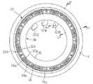
図1はこの発明の実施の形態1に係る回転電機を示す断面図、図2はこの発明の実施の形態1に係る回転電機のステータの結線ユニット装着状態を示す端面図、図3はこの発明の実施の形態1に係る回転電機のステータを示す端面図、図4は図2のIV−IV矢視断面図、図5は図2のV−V矢視断面図、図6および図7はそれぞれこの発明の実施の形態1に係る回転電機のステータのカバー装着状態を示す要部断面図、図8はこの発明の実施の形態1に係る回転電機のステータのコアユニットを示す斜視図、図9はこの発明の実施の形態1に係る回転電機のステータコイルの結線図、図10はこの発明の実施の形態1に係る回転電機のステータコイルの結線ユニットのインサートモールド成形前の状態を示す端面図、図11はこの発明の実施の形態1に係る回転電機のステータコイルの結線ユニットに適用されるバスバーを示す端面図、図12はこの発明の実施の形態1に係る回転電機のステータコイルの結線ユニットに適用されるバスバーの成形方法を説明する工程図、図13はこの発明の実施の形態1に係る回転電機におけるステータへの結線ユニットの組立方法を説明する要部端面図、図14はこの発明の実施の形態1に係る回転電機におけるステータへの結線ユニットの組立方法を説明する要部断面図、図15はこの発明の実施の形態1に係る回転電機のステータコイルの結線ユニットに適用される中性点結線用バスバーの実施態様を示す端面図である。なお、図6および図7は、それぞれ、図4および図5に示される要部断面図のカバー装着状態を示している。
1 is a cross-sectional view showing a rotating electrical machine according to
図1において、回転電機100は、ハウジング1と、ハウジング1内に回転可能に配設されるロータ6と、ロータ6を囲繞するようにハウジング1内に保持されるステータ20と、ステータ20の軸方向一端に配設される結線ユニット30と、を備える。 In FIG. 1, a rotating
ハウジング1は、第1および第2ブラケット2,3と、第1および第2ブラケット2,3に軸方向両側から挟持され、第1および第2ブラケット2,3を締着するボルト5の締着力により第1および第2ブラケット2,3に保持される金属製の円筒状フレーム4と、を備える。 The
ロータ6は、例えば、8極のマグネット8が外周面に接着などにより固着されたロータコア7と、ロータコア7の軸心位置に挿通、固定されるシャフト9と、ロータコア7の軸方向両端面に固着された冷却ファン10と、を備える。そして、ロータ6は、第1および第2ブラケット2,3に設けられた第1および第2ベアリング11,12にシャフト9を回転可能に支持されて、ハウジング1内に回転可能に配設される。 The
ステータ20は、円環状のステータコア21と、ステータコア21に巻装されたステータコイル23と、を備えている。ステータコイル23は、後述するように、12本の集中巻コイル24からなり、12本の集中巻コイル24がステータ20の軸端に配設された結線ユニット30により結線されて、図9に示されるように、それぞれ4本の集中巻コイル24が並列接続されたU相巻線、V相巻線およびW相巻線をY結線してなる3相交流巻線に構成されている。 The
つぎに、ステータ20の構成について具体的に説明する。 Next, the configuration of the
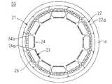
ステータコア21は、図3および図8に示されるように、断面円弧状のコアバック部22aとコアバック部22aの内周面の周方向中央部から径方向内方に突設されたティース22bとからなる断面T字状のコアブロック22を、周方向に12個配列して、円環状に構成されている。 As shown in FIGS. 3 and 8, the
コイルボビン26は、ナイロンなどの絶縁性樹脂の樹脂成型体であり、コアブロック22の軸方向両端に配設される。集中巻コイル24は、図8に示されるように、絶縁被覆された導体線を、コアブロック22のティース22bおよびコイルボビン26周りに所定回巻回して作製される。 The
ステータ20は、集中巻コイル24が巻回された12個のコアブロック22を、コアバック部22aの周方向側面同士を突き合わせて周方向に配列して円筒状フレーム4内に挿入し、焼きばめなどにより固定されて作製される。このように構成されたステータ20では、2本のコイル端末24a,24bが集中巻コイル24のそれぞれから軸方向一側に延出している。そして、コアバック部22aが周方向に連なって配列され、ステータコア21の円環状のコアバックを構成する。 The
つぎに、結線ユニット30の構成について図4、図5、図10および図11を用いて説明する。Next, the configuration of the
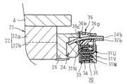
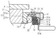
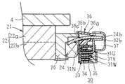
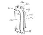
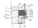
結線ユニット30は、図4、図5および図10に示されるように、集中巻コイル24の所定の結線を行う複数のバスバー31N、31U、31V、31Wと、複数のバスバー31N、31U、31V、31Wを収納保持する絶縁ホルダ33と、インサートモールド成形によりバスバー31N、31U、31V、31Wが収納保持された絶縁ホルダ33を埋設するように形成された外装モールド部材35と、を備える。 As shown in FIGS. 4, 5, and 10, the
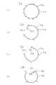
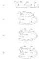
バスバー31Nは、中性点結線用のバスバーであり、図11の(a)に示されるように、帯状平板を厚み方向に曲げて形成された円環状の基部31aと、それぞれ基部31aの幅方向一側から厚み方向に曲げられて径方向外方に延出して、周方向に等角ピッチで12本配列されたコイル接続端子32aと、を備えている。 The
バスバー31Uは、U相結線用のバスバーであり、図11の(b)に示されるように、帯状平板を厚み方向に曲げられて形成され、円弧の一部が欠落した欠落部32cを有する、バスバー31Nの基部31aより小径の不完全円環状の基部31bと、それぞれ基部31bの幅方向一側から厚み方向に曲げられて径方向外方に延出し、周方向に等角ピッチで4本配列されたコイル接続端子32bと、基部31bの周方向一端の幅方向一側から厚み方向に曲げられて径方向内方に延出している外部給電端子32Uと、を備えている。 The
バスバー31Vは、V相結線用のバスバーであり、図11の(c)に示されるように、帯状平板を厚み方向に曲げて形成され、円弧の一部が欠落した欠落部32cを有する、バスバー31Uの基部31bより小径の不完全円環状の基部31bと、それぞれ基部31bの幅方向一側から厚み方向に曲げられて径方向外方に延出し、周方向に等角ピッチで4本配列されたコイル接続端子32bと、基部31bの周方向一端の幅方向一側から厚み方向に曲げられて径方向内方に延出している外部給電端子32Vと、を備えている。 The
バスバー31Wは、W相結線用のバスバーであり、図11の(d)に示されるように、帯状平板を厚み方向に曲げられて形成され、円弧の一部が欠落した欠落部32cを有する、バスバー31Vの基部31bより小径の不完全円環状の基部31bと、それぞれ基部31bの幅方向一側から厚み方向に曲げられて径方向外方に延出し、周方向に等角ピッチで4本配列されたコイル接続端子32bと、基部31bの周方向一端の幅方向一側から厚み方向に曲げられて径方向内方に延出している外部給電端子32Wと、を備えている。 The
なお、基部31a,31bの周方向とは、帯状平板の長さ方向に相当し、基部31a,31bの厚み方向および幅方向とは、帯状平板の長さ方向と直交する矩形断面における短辺および長辺に沿った方向に相当する。
また、集中巻コイル24のコイル端末24aがコイル接続端子32aに接続され、コイル端末24bがコイル接続端子32bに接続される。The circumferential direction of the
Further, the coil terminal 24a of the concentrated winding
ここで、プレス成形機(図示せず)を用いたバスバー31Uの製造方法について図12を参照しつつ説明する。 Here, a manufacturing method of the
まず、図12の(a)に示されるように、板厚1mm程度の銅板などからなる帯状導電部材から、コイル接続端子32bおよび外部給電端子32Uが幅方向の一側に延出する所定長さの帯状平板の基部31bを打ち抜く。ついで、図12の(b)に示されるように、基部31bを厚み方向に曲げて、円弧の一部が欠落した不完全円環状に形成する。ついで、図12の(c)に示されるように、コイル接続端子32bのそれぞれを厚み方向に直角に折り曲げて径方向外方に延出させ、外部給電端子32Uを厚み方向に直角に折り曲げて径方向内方に延出させる。さらに、図12の(d)に示されるように、コイル接続端子32b及び外部給電端子32Uのそれぞれの先端側を厚み方向に直角に折り曲げ、バスバー31Uが得られる。なお、基部31b、コイル接続端子32bおよび外部給電端子32Uは断面矩形(断面長方形)となっている。 First, as shown in FIG. 12A, a predetermined length by which the
なお、説明の便宜上、バスバー31Uの製造工程を複数の工程に分けて説明しているが、基部31bの曲げ工程と、コイル接続端子32および外部給電端子32Uの曲げ工程とを同時に行うようにしてもよい。
また、バスバー31N,31V,31Wもプレス成形機を用いて同様に作製されるので、ここではその説明を省略する。For convenience of explanation, the manufacturing process of the
In addition, the bus bars 31N, 31V, 31W are similarly manufactured using a press molding machine, and thus the description thereof is omitted here.
絶縁ホルダ33は、図4、図5および図10に示されるように、ナイロンなどの絶縁性樹脂を用いて円環状に作製され、4つの円環状のバスバー収納溝34が同心円状に凹設されている。4つのバスバー収納溝34は、それぞれ、バスバー31N,31U,31V,31Wの基部31a,31bを収納可能に絶縁ホルダ33に形成されている。 As shown in FIGS. 4, 5, and 10, the insulating
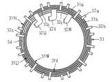
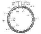
そして、バスバー31Nがその基部31aを最外周に位置するバスバー収納溝34内に挿入して、絶縁ホルダ33に装着される。ついで、バスバー31Uが、その基部31bを外周側から2番目のバスバー収納溝34内に挿入して、絶縁ホルダ33に装着される。ついで、バスバー31Vが、外部給電端子32Uを基部31bの欠落部32c内に入れるように、その基部31bを外周側から3番目のバスバー収納溝34内に挿入して、絶縁ホルダ33に装着される。さらに、バスバー31Wが、外部給電端子32U,32Vを基部31bの欠落部32c内に入れるように、その基部31bを外周側から4番目のバスバー収納溝34内に挿入して、絶縁ホルダ33に装着される。 The
これにより、図10に示されるように、バスバー31N,31U,31V,31Wが絶縁ホルダ33に組み付けられる。そして、絶縁ホルダ33から径方向外方に延出するコイル接続端子32a,32bの対が、等角ピッチで12対配列されている。外部給電端子32Uがバスバー31V,31Wの基部31bの欠落部32c上を通って絶縁ホルダ33から径方向内方に延出し、外部給電端子32Vがバスバー31Wの基部31bの欠落部32c上を通って絶縁ホルダ33から径方向内方に延出している。 As a result, as shown in FIG. 10, the bus bars 31N, 31U, 31V, and 31W are assembled to the insulating
ついで、バスバー31N,31U,31V,31Wが組み付けられた絶縁ホルダ33は、型割り方向を絶縁ホルダ33の軸方向とするモールド型内に挿入される。そして、コイル接続端子32a,32bおよび外部給電端子32U,32V,32Wの断面矩形の長辺で構成される両平面がモールド型の合わせ面で押えられ、ナイロンなどの絶縁性樹脂によりインサートモールド成形され、結線ユニット30が作製される。これにより、絶縁ホルダ33、基部31a,31b、コイル接続端子32a,32bの根元側および外部給電端子32U,32V,32Wの根元側が円環状の外装モールド部材35に埋設され、コイル接続端子32a,32bが外装モールド部材35の外周壁面から径方向外側に延出し、外部給電端子32U,32V,32Wが外装モールド部材35の内周壁面から径方向内方に延出している。さらに、外装モールド部材35から延出するコイル接続端子32a,32bおよび外部給電端子32U,32V,32Wの断面矩形の長辺で構成される両平面が、それぞれ面一となっている。 Next, the insulating
コイル端末ガイド部材36は、ナイロンなどの絶縁性樹脂の樹脂成型体であり、図5および図13の(b)に示されるように、コイル端末24a,24bに対応するように、周方向に24個配列され、それぞれ、口開き状のガイド穴36bを有するガイド部36aと、ガイド部36aを連結して一体に保持する円環状の連結部36cと、を備える。また、ガイド部36aは、そのガイド穴36bの先細り側の開口が結線ユニット30の周方向に配列されているコイル接続端子32a,32bの延出端の外径側近傍に位置するように、連結部36cに保持されている。
カバー37は、ナイロンなどの絶縁性樹脂を用いて、コイル端末24a,24bとコイル接続端子32a,32bとの接合部を覆う円環状に作製されている。The coil
The
このように構成された結線ユニット30を用いてステータ20の集中巻コイル24を結線する手順について図13および図14を参照しつつ説明する。 A procedure for connecting the concentrated winding
まず、ステータ20が、組み立てられる。そして、ステータ20の要部の端面が図13の(a)に示され、要部の断面が図14の(a)に示される。
ついで、コイル端末ガイド部材36を、ガイド穴36bの口開き側をステータ20に向けて、軸方向からステータ20の軸方向一端面に近づける。これにより、コイル端末24a,24bが、図13の(b)および図14の(b)に示されるように、ガイド穴36b内を通ってガイド部36aから延出する。First, the
Next, the coil
ついで、結線ユニット30を、コイル接続端子32a,32bがガイド部36aから延出するコイル端末24a,24bと相対するように周方向の位置決めがなされて、軸方向からステータ20の軸方向一端面に近づける。これにより、結線ユニット30が、図13の(c)および図14の(c)に示されるように、集中巻コイル24に接して集中巻コイル24の軸方向外側、かつコイル端末ガイド部材36の内径側に配設される。このとき、結線ユニット30は、ステータコア21のコアバック、すなわちコアブロック22のコアバック部22aに対して、内径側に位置している。 Next, the
ついで、コイル端末24a,24bとコイル接続端子32a,32bとを溶接などにより接合し、結線ユニット30が、図2に示されるように、ステータ20の軸方向一端に組み付けられる。これにより、12本の集中巻コイル24は結線ユニット30により結線され、図9に示されるように、それぞれ4本の集中巻コイル24が並列接続されたU相巻線、V相巻線およびW相巻線をY結線してなる3相交流巻線に構成される。 Next, the
さらに、カバー37が、図13の(d)および図14の(d)に示されるように、軸方向から結線ユニット30に装着される。これにより、結線ユニット30およびコイル接続端子32a,32bとコイル端末24a,24bとの接合部が、図6および図7に示されるように、カバー37により覆われる。 Further, as shown in FIG. 13D and FIG. 14D, the
このように構成された回転電機100は、交流電力が外部電源より外部給電端子32U,32V,32Wを介してステータコイル23に給電され、ロータ6が回転駆動される。この回転電機100は、磁極数8、スロット数12のインナーロータ型の3相モータとして動作する。In the rotating
この実施の形態1によれば、バスバー31Nが、円環状の基部31aと、それぞれ基部31aの幅方向一側から径方向外方に延出して、周方向に等角ピッチで12本配列されたコイル接続端子32aと、を備えている。バスバー31U、31V,31Wが、欠落部32cを有する不完全円環状の基部31bと、それぞれ基部31bの幅方向一側から径方向外方に延出し、周方向に等角ピッチで4本配列されたコイル接続端子32bと、基部31bの周方向一端の幅方向一側から径方向内方に延出している外部給電端子32U、32V,32Wと、を備えている。 According to the first embodiment, the bus bars 31N are arranged in an
そして、基部31aを絶縁ホルダ33の最外周のバスバー収納溝34に挿入してバスバー31Nを絶縁ホルダ33に装着し、ついで基部31bを外周側から2番目のバスバー収納溝34に挿入してバスバー31Uを絶縁ホルダ33に装着する。ついで、すでに装着されているバスバー31Uの外部給電端子32Uを基部31bの欠落部32c内に入れるように、基部31bを外周側から3番目のバスバー収納溝34に挿入してバスバー31Vを絶縁ホルダ33に装着する。さらに、すでに装着されているバスバー31U,31Vの外部給電端子32U,32Vを基部31bの欠落部32c内に入れるように、基部31bを外周側から4番目のバスバー収納溝34に挿入してバスバー31Wを絶縁ホルダ33に装着している。 Then, the
この組み立て手順によれば、コイル接続端子32a,32bが径方向外方に曲げられ、外部給電端子32U,32V,32Wが径方向内方に曲げられたバスバー31N,31U,31V,31Wを互いに干渉することなく絶縁ホルダ33に装着できる。そこで、バスバー31N,31U,31V,31Wを絶縁ホルダ33に装着した後、コイル接続端子32a,32bあるいは外部給電端子32U,32V,32Wを曲げる煩雑な曲げ工程および曲げ工程で用いられる治具などが不要となり、結線ユニット30の組立性が向上し、低コスト化が図られる。
バスバー31N,31U,31V,31Wを絶縁ホルダ33に装着する前に、コイル接続端子32a,32bおよび外部給電端子32U,32V,32Wを曲げているので、曲げ加工部の寸法精度が高められる。According to this assembly procedure, the
Since the
コイル接続端子32a,32bおよび外部給電端子32U,32V,32Wが基部31a,31bの厚み方向に直角に曲げられている。そこで、モールド型の型割り方向を円環状の絶縁ホルダ33の軸方向とし、コイル接続端子32a,32bおよび外部給電端子32U,32V,32Wの断面矩形の長辺で構成される両平面をモールド型の合わせ面で押えてインサートモールド成形することができる。このように、コイル接続端子32a,32bおよび外部給電端子32U,32V,32Wの断面矩形の長辺で構成される両平面をシール面としてインサートモールド成形できるので、インサートモールド成形時のシールが簡易となる。 The
結線ユニット30が周方向に環状に配列されている集中巻コイル24の軸方向外側に配設されている。そこで、コイル端末24a,24bとコイル接続端子32a,32bとの接合部が、結線作業スペースの広い集中巻コイル24の外径側に位置し、接合時の作業効率が向上する。さらに、結線ユニット30の径方向幅を内径側に広げ、バスバー31N,31U,31V,31Wの板厚を厚くすることが可能となるので、回転電機100の大型化をまねくことなく、給電電流の大電流化に簡易に対応することができる。 The
コイル接続端子32a,32bと外部給電端子32U,32V,32Wとが径方向の逆方向に延出しているので、コイル接続端子32a,32bの接続用治具と、外部給電端子32U,32V,32Wの接続用治具との干渉がなく、接合時の作業効率が向上する。
コイル端末24a,24bが口開き状のガイド穴36bに口開き側から挿通されるようにコイル端末ガイド部材36を装着しているので、コイル端末24a,24bは口開き状のガイド穴36bに案内されてガイド部36aから延出する。そこで、コイル端末24a,24bの先端がコイル接続端子32a,32bの先端に沿うように周方向に配列され、コイル端末24a,24bとコイル接続端子32a,32bとの接合作業が簡易となる。
カバー37がコイル端末24a,24bとコイル接続端子32a,32bとの接合部を覆うように結線ユニット30に装着されているので、絶縁性が向上される。Since the
Since the coil
Since the
なお、上記実施の形態1では、バスバー31Nが円環状に作製されているものとしているが、バスバー31Nは、図15の(a)に示されるように、欠落部を有する不完全円環状であってよい。さらには、バスバー31Nは、図15の(b)に示されるように、3つのコイル接続端子32aを有する円弧状の基部31cを、周方向に4つ配列して構成されてもよい。 In the first embodiment, the
実施の形態2.
図16はこの発明の実施の形態2に係る回転電機のステータの結線ユニット装着状態を示す端面図、図17は図16のXVII−XVII矢視断面図、図18はこの発明の実施の形態2に係る回転電機のステータコイルの結線ユニットのインサートモールド成形前の状態を示す端面図、図19はこの発明の実施の形態2に係る回転電機のステータコイルの結線ユニットに適用されるバスバーを示す端面図である。
FIG. 16 is an end view showing a stator connection unit mounted state of a rotary electric machine according to
図16乃至図18において、結線ユニット40は、集中巻コイル24の所定の結線を行う複数のバスバー41N、41U、41V、41Wと、複数のバスバー41N、41U、41V、41Wを収納保持する絶縁ホルダ33と、インサートモールド成形によりバスバー41N、41U、41V、41Wが収納保持された絶縁ホルダ33を埋設するように形成された外装モールド部材35と、を備える。 16 to 18, the
バスバー41Uは、U相結線用のバスバーであり、図19の(a)に示されるように、帯状平板を厚み方向に曲げられて形成され、円弧の一部が欠落した欠落部42cを有する不完全円環状の基部41bと、それぞれ基部41bの幅方向一側から厚み方向に曲げられて径方向内方に延出し、周方向に等角ピッチで4本配列されたコイル接続端子42bと、基部41bの周方向一端の幅方向一側から厚み方向に曲げられて径方向外方に延出している外部給電端子42Uと、を備えている。 The
バスバー41Vは、V相結線用のバスバーであり、図19の(b)に示されるように、帯状平板を厚み方向に曲げて形成され、円弧の一部が欠落した欠落部42cを有する、バスバー41Uの基部41bより小径の不完全円環状の基部41bと、それぞれ基部41bの幅方向一側から厚み方向に曲げられて径方向内方に延出し、周方向に等角ピッチで4本配列されたコイル接続端子42bと、基部41bの周方向一端の幅方向一側から厚み方向に曲げられて径方向外方に延出している外部給電端子42Vと、を備えている。 The
バスバー41Wは、W相結線用のバスバーであり、図19の(c)に示されるように、帯状平板を厚み方向に曲げられて形成され、円弧の一部が欠落した欠落部42cを有する、バスバー41Vの基部41bより小径の不完全円環状の基部41bと、それぞれ基部41bの幅方向一側から厚み方向に曲げられて径方向内方に延出し、周方向に等角ピッチで4本配列されたコイル接続端子42bと、基部41bの周方向他端の幅方向一側から厚み方向に曲げられて径方向外方に延出している外部給電端子42Wと、を備えている。 The
バスバー41Nは、中性点結線用のバスバーであり、図19の(d)に示されるように、帯状平板を厚み方向に曲げて形成された、バスバー41Wの基部41bより小径の円環状の基部41aと、それぞれ基部41aの幅方向一側から厚み方向に曲げられて径方向内方に延出して、周方向に等角ピッチで12本配列されたコイル接続端子42aと、を備えている。 The
なお、集中巻コイル24のコイル端末24aがコイル接続端子42aに接続され、コイル端末24bがコイル接続端子42bに接続される。 In addition, the coil terminal 24a of the concentrated winding
つぎに、結線ユニット40の製造方法について説明する。 Next, a method for manufacturing the
まず、バスバー41U,41V,41W,41Nが、バスバー31U,31V,31W,31Nと同様に、板厚1mm程度の銅板などからなる帯状導電部材から、プレス成形機を用いて、作製される。
そして、バスバー41Nがその基部41aを最内周に位置するバスバー収納溝34内に挿入して、絶縁ホルダ33に装着される。ついで、バスバー41Wが、その基部41bを内周側から2番目のバスバー収納溝34内に挿入して、絶縁ホルダ33に装着される。ついで、バスバー41Vが、外部給電端子42Wを基部41bの欠落部42c内に入れるように、その基部41bを内周側から3番目のバスバー収納溝34内に挿入して、絶縁ホルダ33に装着される。さらに、バスバー41Uが、外部給電端子42V,42Wを基部41bの欠落部42c内に入れるように、その基部41bを内周側から4番目、すなわち最外周のバスバー収納溝34内に挿入して、絶縁ホルダ33に装着される。First, the bus bars 41U, 41V, 41W, and 41N are manufactured from a strip-shaped conductive member made of a copper plate having a thickness of about 1 mm using a press molding machine, like the bus bars 31U, 31V, 31W, and 31N.
Then, the
これにより、図18に示されるように、バスバー41N,41U,41V,41Wが絶縁ホルダ33に組み付けられる。そして、絶縁ホルダ33から径方向内方に延出するコイル接続端子42a,42bの対が、等角ピッチで12対配列されている。外部給電端子42Wがバスバー41U,41Vの基部41bの欠落部42c上を通って絶縁ホルダ33から径方向外方に延出し、外部給電端子42Vがバスバー41Uの基部41bの欠落部42c上を通って絶縁ホルダ33から径方向外方に延出している。 As a result, as shown in FIG. 18, the bus bars 41N, 41U, 41V, 41W are assembled to the insulating
ついで、バスバー41N,41U,41V,41Wが組み付けられた絶縁ホルダ33は、型割り方向を絶縁ホルダ33の軸方向とするモールド型内に挿入される。そして、コイル接続端子42a,42bおよび外部給電端子42U,42V,42Wの断面矩形の長辺で構成される両平面がモールド型の合わせ面で押えられ、ナイロンなどの絶縁性樹脂によりインサートモールド成形され、結線ユニット40が作製される。これにより、絶縁ホルダ33、基部41a,41b、コイル接続端子42a,42bの根元側および外部給電端子42U,42V,42Wの根元側が円環状の外装モールド部材35に埋設され、コイル接続端子42a,42bが外装モールド部材35の内周壁面から径方向内側に延出し、外部給電端子42U,42V,42Wが外装モールド部材35の外周壁面から径方向外方に延出している。さらに、外装モールド部材35から延出するコイル接続端子42a,42bおよび外部給電端子42U,42V,42Wの断面矩形の長辺で構成される両平面が、それぞれ面一となっている。 Next, the insulating
このように構成された結線ユニット40を用いてステータ20の集中巻コイル24を結線する手順について説明する。 A procedure for connecting the concentrated winding
まず、結線ユニット40を、コイル接続端子42a,42bがコイル端末24a,24bと相対するように周方向の位置決めがなされて、軸方向からステータ20の軸方向一端面に近づける。これにより、結線ユニット40が、図16および図17に示されるように、コアバック部22aに接してステータコア21の軸方向外側、かつ集中巻コイル24の外径側に配設される。このとき、結線ユニット40は、ステータコア21のティース22bに対して、外径側に位置している。First, the
ついで、コイル端末24a,24bとコイル接続端子42a,42bとを溶接などにより接合し、結線ユニット40がステータ20の軸方向一端に組み付けられる。これにより、12本の集中巻コイル24は結線ユニット40により結線され、実施の形態1と同様に、それぞれ4本の集中巻コイル24が並列接続されたU相巻線、V相巻線およびW相巻線をY結線してなる3相交流巻線に構成される。 Next, the
なお、コイル端末ガイド部材36およびカバー37は用いられていないが、コイル端末ガイド部材36およびカバー37を用いてもよいことは言うまでもないことである。 In addition, although the coil
この実施の形態2では、基部41aを絶縁ホルダ33の最外内のバスバー収納溝34に挿入してバスバー41Nを絶縁ホルダ33に装着し、ついで基部41bを内周側から2番目のバスバー収納溝34に挿入してバスバー41Wを絶縁ホルダ33に装着する。ついで、すでに装着されているバスバー41Wの外部給電端子42Wを基部41bの欠落部42c内に入れるように、基部41bを内周側から3番目のバスバー収納溝34に挿入してバスバー41Vを絶縁ホルダ33に装着する。さらに、すでに装着されているバスバー41V,41Wの外部給電端子42V,42Wを基部41bの欠落部42c内に入れるように、基部41bを内周側から4番目のバスバー収納溝34に挿入してバスバー41Uを絶縁ホルダ33に装着している。 In the second embodiment, the base portion 41a is inserted into the outermost bus
この組み立て手順においても、コイル接続端子42a,42bが径方向内方に曲げられ、外部給電端子42U,42V,42Wが径方向外方に曲げられたバスバー41N,41U,41V,41Wを互いに干渉することなく絶縁ホルダ33に装着できる。そこで、バスバー41N,41U,41V,41Wを絶縁ホルダ33に装着した後、コイル接続端子42a,42bあるいは外部給電端子42U,42V,42Wを曲げる煩雑な曲げ工程および曲げ工程で用いられる治具などが不要となり、結線ユニット40の組立性が向上し、低コスト化が図られる。
バスバー41N,41U,41V,41Wを絶縁ホルダ33に装着する前に、コイル接続端子42a,42bおよび外部給電端子42U,42V,42Wを曲げているので、曲げ加工部の寸法精度が高められる。Also in this assembly procedure, the
Since the
コイル接続端子42a,42bおよび外部給電端子42U,42V,42Wが基部41a,41bの厚み方向に直角に曲げられている。そこで、モールド型の型割り方向を円環状の絶縁ホルダ33の軸方向とし、コイル接続端子42a,42bおよび外部給電端子42U,42V,42Wの断面矩形の長辺で構成される両平面をモールド型の合わせ面で押えてインサートモールド成形することができる。このように、コイル接続端子42a,42bおよび外部給電端子42U,42V,42Wの断面矩形の長辺で構成される両平面をシール面としてインサートモールド成形できるので、インサートモールド成形時のシールが簡易となる。 The
結線ユニット40が周方向に環状に配列されている集中巻コイル24の径方向外側に配設されているので、基部41bから径方向外方に折り曲げられた外部給電端子42U,42V,42Wをそのまま円筒状フレーム4の外部に延出させて、外部電源(図示せず)と直接接続させることができる。そこで、回転電機の軸方向寸法を縮小することができるとともに、外部電源と外部給電端子42U,42V,42Wとの間の接続配線などが不要となり、部品点数を削減できる。 Since the
なお、上記各実施の形態では、回転電機における磁極数とスロット数との比が8:12、即ち極スロット比が2:3であるが、極スロット比は2:3に限定されるものではなく、例えば4:3でもよい。In each of the above embodiments, the ratio of the number of magnetic poles to the number of slots in the rotatingelectrical machine is 8:12, that is, the pole slot ratio is 2: 3, but the pole slot ratio is not limited to 2: 3. For example, it may be 4: 3.
1 ハウジング、2 第1ブラケット、3 第2ブラケット、4 円筒状フレーム、6 ロータ、9 シャフト、20 ステータ、21 ステータコア、22a コアバック部、22b ティース、23 ステータコイル、24 集中巻コイル、24b コイル端末、30,40 結線ユニット、31U,31V,31W,41U,41V,41W バスバー、31b、41b 基部、32b、42b コイル接続端子、32c、42c 欠落部、32U,32V,32W、41U,41V,41W 外部給電端子、33 絶縁ホルダ、34 バスバー収納溝、35 外装モールド部材、36 コイル端末ガイド部材、36a ガイド部、36b ガイド穴、36c 連結部、37 カバー。 DESCRIPTION OF
Claims (6)
Translated fromJapaneseシャフトを上記一対のブラケットに回転可能に支持されて上記ハウジング内に配設されたロータと、
複数のティースが、それぞれ円環状のコアバックの内周壁面から径方向内方に突設されて、周方向に所定のピッチで配列されたステータコア、および該ティースのそれぞれに巻装された複数の集中巻コイルからなるステータコイルを有し、上記ロータを囲繞するように上記円筒状フレームに保持されたステータと、
上記ステータの軸方向一端側に配設され、上記複数の集中巻コイルの所定の結線を行う結線ユニットと、を備えた回転電機において、
上記結線ユニットは、
それぞれ、帯状平板を厚み方向に曲げられて、円弧の一部が欠落した不完全円環状に形成された断面矩形の基部、該基部の周方向の端部の幅方向一側から厚み方向に曲げられて径方向一側に延出する断面矩形の外部給電端子、およびそれぞれ該基部の幅方向一側から厚み方向に曲げられて径方向他側に延出し、該基部の周方向に所定の間隔で配列され、上記集中巻コイルのコイル端末に接続される断面矩形の複数のコイル接続端子を有し、上記ステータコイルの各相に対応して設けられる複数のバスバーと、
複数のバスバー収納溝が同心円状に凹設され、上記基部を該複数のバスバー収納溝のそれぞれに収納して上記複数のバスバーを保持する円環状の絶縁ホルダと、
を備え、
上記複数のバスバーは、上記外部給電端子が、上記絶縁ホルダの径方向一側に位置する上記バスバーの基部の欠落部上を通って径方向一側に延出するように該絶縁ホルダに保持され、
上記結線ユニットは、上記絶縁ホルダおよび上記複数のバスバーの上記基部を埋設する外装モールド部材をさらに備え、
上記外装モールド部材から延出する上記複数のコイル接続端子および上記外部給電端子の断面矩形の長辺により構成される両平面がそれぞれ面一となっていることを特徴とする回転電機。A housing having a cylindrical frame and a pair of brackets disposed at both axial ends of the cylindrical frame;
A rotor rotatably supported by the pair of brackets and disposed in the housing;
A plurality of teeth project radially inward from the inner circumferential wall surface of the annular core back, and are arranged at a predetermined pitch in the circumferential direction, and a plurality of teeth wound around each of the teeth. A stator coil having a concentrated winding coil and held by the cylindrical frame so as to surround the rotor;
A rotating electrical machine including a connection unit disposed on one end side in the axial direction of the stator and performing predetermined connection of the plurality of concentrated winding coils;
The above wiring unit is
Each of the strip-shaped flat plates is bent in the thickness direction, and is bent in the thickness direction from one side in the width direction of the base portion of the rectangular cross section formed in an incomplete annular shape with a part of the arc missing and the circumferential end of the base portion. External feeding terminal having a rectangular cross section extending to one side in the radial direction, and bent in the thickness direction from one side in the width direction of the base and extending to the other side in the radial direction, with a predetermined interval in the circumferential direction of the base A plurality of bus connection terminals arranged in correspondence with each phase of the stator coil, the coil connection terminals having a rectangular cross section connected to the coil terminal of the concentrated winding coil,
A plurality of bus bar storage grooves are concentrically recessed, and an annular insulating holder that holds the plurality of bus bars by storing the base in each of the plurality of bus bar storage grooves,
With
The plurality of bus bars are held by the insulating holder so that the external power supply terminals extend to the one side in the radial direction through the missing portion of the base portion of the bus bar located on the one side in the radial direction of the insulating holder.And
The connection unit further includes an exterior mold member that embeds the base of the insulating holder and the plurality of bus bars,
A rotating electric machine characterized in thatboth planes formed by long sides of a rectangular cross section of the plurality of coil connection terminals and the external power supply terminal extending from the exterior mold member are flush with each other .
上記結線ユニットは、上記集中巻コイルの軸方向外側に配設され、上記複数のコイル接続端子がそれぞれ対応する上記集中巻コイルのコイル端末に接合されていることを特徴とする請求項1記載の回転電機。In the plurality of bus bars, theexternal power supply terminals extend radially inward from the exterior mold member, and the plurality of coil connection terminals extend radially outwardfrom the exterior mold member .
The said connection unit is arrange | positioned in the axial direction outer side of the said concentrated winding coil, The said some coil connection terminal is joined to the coil terminal of the said concentrated winding coil to respectively correspond. Rotating electric machine.
上記結線ユニットは、上記ステータコアのコアバックの軸方向外側に配設され、上記複数のコイル接続端子がそれぞれ対応する上記集中巻コイルのコイル端末に接合されていることを特徴とする請求項1記載の回転電機。In the plurality of bus bars, theexternal power supply terminal extends radially outward from the exterior mold member, and the plurality of coil connection terminals extend radially inwardfrom the exterior mold member .
2. The wiring unit according to claim 1, wherein the wiring unit is disposed on an axially outer side of a core back of the stator core, and the plurality of coil connection terminals are respectively joined to coil terminals of the corresponding concentrated winding coils. Rotating electric machine.
複数のバスバー収納溝が同心円状に凹設され、上記基部を該複数のバスバー収納溝のそれぞれに収納して上記複数のバスバーを保持する円環状の絶縁ホルダと、
を備えた回転電機のステータコイルの結線ユニットの製造方法において、
上記複数のバスバーを形成する工程と、
上記複数のバスバーの基部を、上記絶縁ホルダの径方向他側に位置するバスバーから順に、かつ径方向他側の上記バスバー収納溝に収納されているバスバーの基部から径方向一側に延出している上記外部給電端子を基部の欠落部内に入れるように、該バスバー収納溝に収納させて、該複数のバスバーを該絶縁ホルダに装着する工程と、
モールド型の型割り方向を上記絶縁ホルダの軸方向とし、上記絶縁ホルダから径方向に延出する上記複数のコイル接続端子および上記外部給電端子の断面矩形の長辺により構成される両平面を該モールド型の合わせ面で押えて、上記複数のバスバーが装着された上記絶縁ホルダをインサートモールド成形する工程と、
を有することを特徴とする回転電機のステータコイルの結線ユニットの製造方法。Each of the strip-shaped flat plates is bent in the thickness direction, and is bent in the thickness direction from one side in the width direction of the base portion of the rectangular cross section formed in an incomplete annular shape with a part of the arc missing and the circumferential end of the base portion. External feeding terminal having a rectangular cross section extending to one side in the radial direction, and bent in the thickness direction from one side in the width direction of the base and extending to the other side in the radial direction, with a predetermined interval in the circumferential direction of the base And a plurality of bus bars provided corresponding to each phase of the stator coil, having a plurality of rectangular coil connection terminals connected to the coil terminals of the concentrated winding coil constituting the stator coil, and
A plurality of bus bar storage grooves are concentrically recessed, and an annular insulating holder that holds the plurality of bus bars by storing the base in each of the plurality of bus bar storage grooves,
In a method for manufacturing a stator coil connection unit of a rotating electrical machine comprising:
Forming the plurality of bus bars;
The bases of the plurality of bus bars are extended in order from the bus bar located on the other radial side of the insulating holder and from the base of the bus bar housed in the bus bar housing groove on the other radial side to one side in the radial direction. A step of accommodating the plurality of bus bars in the insulating holder so that the external power feeding terminal is placed in the bus bar housing groove so as to be put in the missing portion of the base; and
Both planes formed by the long sides of the cross-sectional rectangles of the plurality of coil connection terminals and the external power supply terminals extending in the radial direction from the insulation holder, with the mold dividing direction of the mold as the axial direction of the insulation holder, A step of insert-molding the insulating holder on which the plurality of bus bars are mounted by pressing the mating surfaces of the molds;
A method of manufacturing a stator coil connection unit for a rotating electrical machine.
Priority Applications (4)
| Application Number | Priority Date | Filing Date | Title |
|---|---|---|---|
| JP2011245274AJP5452570B2 (en) | 2011-11-09 | 2011-11-09 | Rotating electric machine and method of manufacturing stator coil connection unit |
| US13/450,098US8878407B2 (en) | 2011-11-09 | 2012-04-18 | Rotary electric machine and method for manufacturing a stator coil connecting unit therefor |
| CN201210211055.8ACN103107625B (en) | 2011-11-09 | 2012-06-25 | Rotary electric machine and method for manufacturing a stator coil connecting unit |
| DE102012212096ADE102012212096A1 (en) | 2011-11-09 | 2012-07-11 | A rotary electric machine and method of manufacturing a stator coil connection unit therefor |
Applications Claiming Priority (1)
| Application Number | Priority Date | Filing Date | Title |
|---|---|---|---|
| JP2011245274AJP5452570B2 (en) | 2011-11-09 | 2011-11-09 | Rotating electric machine and method of manufacturing stator coil connection unit |
Publications (2)
| Publication Number | Publication Date |
|---|---|
| JP2013102633A JP2013102633A (en) | 2013-05-23 |
| JP5452570B2true JP5452570B2 (en) | 2014-03-26 |
Family
ID=48145333
Family Applications (1)
| Application Number | Title | Priority Date | Filing Date |
|---|---|---|---|
| JP2011245274AExpired - Fee RelatedJP5452570B2 (en) | 2011-11-09 | 2011-11-09 | Rotating electric machine and method of manufacturing stator coil connection unit |
Country Status (4)
| Country | Link |
|---|---|
| US (1) | US8878407B2 (en) |
| JP (1) | JP5452570B2 (en) |
| CN (1) | CN103107625B (en) |
| DE (1) | DE102012212096A1 (en) |
Cited By (1)
| Publication number | Priority date | Publication date | Assignee | Title |
|---|---|---|---|---|
| US11967873B2 (en) | 2019-09-23 | 2024-04-23 | Canoo Technologies Inc. | Fractional slot electric motors with coil elements having rectangular cross-sections |
Families Citing this family (45)
| Publication number | Priority date | Publication date | Assignee | Title |
|---|---|---|---|---|
| JP6073702B2 (en)* | 2013-02-22 | 2017-02-01 | 住友電装株式会社 | Centralized power distribution member of motor |
| JP6073703B2 (en)* | 2013-02-22 | 2017-02-01 | 住友電装株式会社 | Centralized power distribution member of motor |
| CN105164899B (en)* | 2013-04-19 | 2017-11-28 | 三菱电机株式会社 | rotating electrical machine |
| JP5958767B2 (en)* | 2013-06-03 | 2016-08-02 | 住友電装株式会社 | Manufacturing method of bus burring |
| KR102051599B1 (en)* | 2013-09-16 | 2020-01-08 | 엘지이노텍 주식회사 | Busbar, insulator and motor including the same |
| CN105099036A (en)* | 2014-05-12 | 2015-11-25 | 舍弗勒技术股份两合公司 | Motor, manufacturing method thereof and vehicle driving device |
| EP3154159B1 (en)* | 2014-06-09 | 2020-05-06 | Nissan Motor Co., Ltd | Flat-wire stator coil manufacturing method |
| DE102015225088A1 (en) | 2014-12-26 | 2016-06-30 | Nidec Corporation | Engine and method of making same |
| KR102301927B1 (en)* | 2014-12-29 | 2021-09-14 | 엘지이노텍 주식회사 | Stator assembly, Motor having the same and Method for manufacturing of the same |
| DE112015006399T5 (en)* | 2015-03-31 | 2017-12-14 | Mitsubishi Electric Corporation | ELECTRICAL ROTATION MACHINE |
| CN107431406B (en) | 2015-04-06 | 2019-06-18 | 三菱电机株式会社 | Rotating electric machine |
| DE102015212821A1 (en)* | 2015-07-09 | 2017-01-12 | Brose Fahrzeugteile GmbH & Co. Kommanditgesellschaft, Würzburg | Stator assembly, rotary electric machine and method of manufacturing a stator assembly |
| JP6439622B2 (en)* | 2015-07-31 | 2018-12-19 | 株式会社デンソー | Rotating electric machine stator |
| US10862363B2 (en)* | 2015-08-10 | 2020-12-08 | Nidec Corporation | Motor |
| JP5963928B1 (en)* | 2015-08-28 | 2016-08-03 | 三菱電機株式会社 | Rotating machine wiring unit |
| JP6139723B1 (en)* | 2016-02-25 | 2017-05-31 | 三菱電機株式会社 | Rotating electric machine and manufacturing method thereof |
| CN107134873B (en)* | 2016-02-26 | 2021-02-09 | 博世汽车部件(长沙)有限公司 | Support module and motor |
| EP3425776B1 (en) | 2016-03-02 | 2021-05-05 | LG Innotek Co., Ltd. | Busbar assembly and motor comprising same |
| EP3249662B1 (en)* | 2016-05-27 | 2020-05-13 | Hanning Elektro-Werke GmbH & Co. KG | Electric pump motor |
| KR102604381B1 (en)* | 2016-07-07 | 2023-11-21 | 엘지이노텍 주식회사 | Stator Unit, Stator and Motor having the same |
| EP3496238B1 (en)* | 2016-08-05 | 2022-02-23 | Nidec Corporation | Motor |
| JP6756546B2 (en)* | 2016-08-30 | 2020-09-16 | 日産自動車株式会社 | Busbar unit |
| US11152828B2 (en)* | 2016-11-16 | 2021-10-19 | Mitsubishi Electric Corporation | Rotating electric machine |
| TWI606676B (en) | 2017-01-06 | 2017-11-21 | 群光電能科技股份有限公司 | Fixing device for junction wires of stator of motor |
| EP3580832A4 (en)* | 2017-02-13 | 2021-03-03 | Milwaukee Electric Tool Corporation | Brushless direct current motor for power tools |
| JP6628756B2 (en)* | 2017-03-23 | 2020-01-15 | 本田技研工業株式会社 | Power supply for rotating electric machine |
| KR102343086B1 (en) | 2017-04-26 | 2021-12-24 | 엘지이노텍 주식회사 | Motor |
| JP6877242B2 (en)* | 2017-05-29 | 2021-05-26 | 三菱電機株式会社 | Stator of rotary electric machine and its manufacturing method |
| CN109104018B (en)* | 2017-06-21 | 2023-08-01 | 上海海立电器有限公司 | Insulating bracket for motor and winding method thereof |
| CN111434010A (en)* | 2017-11-24 | 2020-07-17 | 日本电产株式会社 | Motor with a stator having a stator core |
| JP6538238B1 (en)* | 2018-05-11 | 2019-07-03 | シナノケンシ株式会社 | Electric pump |
| JP7047682B2 (en)* | 2018-09-13 | 2022-04-05 | 株式会社デンソー | Rotating machine, its stator, and manufacturing method of rotating machine |
| JP7181781B2 (en)* | 2018-12-10 | 2022-12-01 | 株式会社Soken | Rotating electric machine, power converter, and manufacturing method of rotating electric machine |
| EP3985845A4 (en)* | 2019-08-20 | 2022-09-07 | Anhui Welling Auto Parts Co., Ltd. | BUSBAR, MAIN BODY OF A BUSBAR, ENGINE, ELECTRIC POWER STEERING SYSTEM AND VEHICLE |
| TWI699075B (en) | 2019-10-14 | 2020-07-11 | 群光電能科技股份有限公司 | Wire bonding device of stator of motor |
| KR102340953B1 (en)* | 2020-04-24 | 2021-12-17 | 현대트랜시스 주식회사 | Terminal assembly for drive motor |
| KR102351783B1 (en) | 2020-04-24 | 2022-01-17 | (주)타마스 | Hollow Shaft Motor |
| KR102327229B1 (en)* | 2020-05-12 | 2021-11-16 | 현대트랜시스 주식회사 | Terminal assembly for drive motor |
| JP7655756B2 (en)* | 2021-03-29 | 2025-04-02 | ニデック株式会社 | Motor |
| KR102634721B1 (en) | 2021-08-13 | 2024-02-08 | 주식회사 비엠씨 | Hollow Shaft Motor |
| US20240388160A1 (en)* | 2021-11-18 | 2024-11-21 | Lg Innotek Co., Ltd. | Motor |
| EP4481995A1 (en)* | 2022-02-16 | 2024-12-25 | Zhuhai Enpower Electric Co., Ltd. | Stator assembly, electric motor, powertrain and vehicle |
| EP4254742A1 (en) | 2022-03-29 | 2023-10-04 | MAHLE International GmbH | Electric machine |
| IT202200018480A1 (en)* | 2022-09-12 | 2024-03-12 | Ferrari Spa | THREE-PHASE STATOR WINDING OF A ROTATING ELECTRIC MACHINE |
| CN119812878B (en)* | 2025-01-07 | 2025-08-26 | 东莞市达旺精密模具有限公司 | A high-speed data cable housing integrated molding production line |
Family Cites Families (8)
| Publication number | Priority date | Publication date | Assignee | Title |
|---|---|---|---|---|
| DE19920127C2 (en)* | 1999-05-03 | 2001-05-31 | Mannesmann Sachs Ag | Stator for an electrical machine and method for producing a stator |
| JP2003134759A (en)* | 2001-10-26 | 2003-05-09 | Sumitomo Wiring Syst Ltd | Method of manufacturing centralized power distribution member of thin brushless motor for vehicle |
| JP3733312B2 (en)* | 2001-10-26 | 2006-01-11 | 住友電装株式会社 | Manufacturing method of bus bar used for concentrated power distribution member of thin brushless motor for vehicle |
| JP3613262B2 (en) | 2002-04-26 | 2005-01-26 | 三菱電機株式会社 | Rotating electric machine and manufacturing method thereof |
| JP4789676B2 (en)* | 2006-03-29 | 2011-10-12 | トヨタ自動車株式会社 | Terminal module for rotating electric machine and rotating electric machine |
| JP5001723B2 (en)* | 2007-06-12 | 2012-08-15 | 富士重工業株式会社 | Electric motor |
| JP2009033848A (en)* | 2007-07-26 | 2009-02-12 | Keihin Corp | Brushless motor |
| JP4465395B2 (en)* | 2008-04-15 | 2010-05-19 | 本田技研工業株式会社 | Rotating electrical power collection and distribution ring |
- 2011
- 2011-11-09JPJP2011245274Apatent/JP5452570B2/ennot_activeExpired - Fee Related
- 2012
- 2012-04-18USUS13/450,098patent/US8878407B2/ennot_activeExpired - Fee Related
- 2012-06-25CNCN201210211055.8Apatent/CN103107625B/ennot_activeExpired - Fee Related
- 2012-07-11DEDE102012212096Apatent/DE102012212096A1/ennot_activeWithdrawn
Cited By (1)
| Publication number | Priority date | Publication date | Assignee | Title |
|---|---|---|---|---|
| US11967873B2 (en) | 2019-09-23 | 2024-04-23 | Canoo Technologies Inc. | Fractional slot electric motors with coil elements having rectangular cross-sections |
Also Published As
| Publication number | Publication date |
|---|---|
| CN103107625A (en) | 2013-05-15 |
| DE102012212096A1 (en) | 2013-05-16 |
| CN103107625B (en) | 2015-06-17 |
| JP2013102633A (en) | 2013-05-23 |
| US8878407B2 (en) | 2014-11-04 |
| US20130113313A1 (en) | 2013-05-09 |
Similar Documents
| Publication | Publication Date | Title |
|---|---|---|
| JP5452570B2 (en) | Rotating electric machine and method of manufacturing stator coil connection unit | |
| US8922080B2 (en) | Bus bar, motor, and process for producing these | |
| JP5703604B2 (en) | Bus bar unit and motor | |
| US10892658B2 (en) | Motor with bus-bar assembly | |
| US7936116B2 (en) | Motor stator with improved end surface insulating plate, motor including the motor stator, pump including the motor stator, and manufacturing the motor stator | |
| JP5740930B2 (en) | Stator and motor | |
| JP5377702B2 (en) | Rotating electric machine and manufacturing method thereof | |
| JP4688910B2 (en) | Electric power steering motor | |
| US20110018376A1 (en) | Busbar terminal, busbar unit, and motor | |
| JP2009261082A (en) | Electric power collection/distribution ring of rotary electric machine | |
| JP6444930B2 (en) | Electric motor provided with a wiring board configured by crimping and connecting windings | |
| CN107846099A (en) | Stator and the method for manufacturing stator | |
| JP2009261094A (en) | Power collection/distribution structure of rotary electric machine | |
| US20100236059A1 (en) | Stator manufacturing apparatus | |
| CN113454880B (en) | Stator of rotating electric machine, rotating electric machine, method for manufacturing stator of rotating electric machine, and method for manufacturing rotating electric machine | |
| WO2019142289A1 (en) | Electric motor and air conditioner | |
| JP4915241B2 (en) | Stator lead wire mounting structure for rotating electrical machines | |
| CN118826344A (en) | Electric machine, stator for an electric machine and method for producing such a stator | |
| JP5111887B2 (en) | Rotating electric machine stator | |
| JP2010183660A (en) | Stator, brushless motor, method of manufacturing the stator, and method of manufacturing the brushless motor | |
| JP4465396B2 (en) | Distribution connection structure for rotating electrical machine and method for manufacturing distribution connection structure for rotating electrical machine | |
| JP5688981B2 (en) | Positioning device and electric motor | |
| JP5563876B2 (en) | Coil manufacturing method and motor | |
| JP7631634B2 (en) | Stator, motor, and method for manufacturing a stator | |
| JP4549813B2 (en) | Stator and brushless motor |
Legal Events
| Date | Code | Title | Description |
|---|---|---|---|
| A131 | Notification of reasons for refusal | Free format text:JAPANESE INTERMEDIATE CODE: A131 Effective date:20130820 | |
| A521 | Written amendment | Free format text:JAPANESE INTERMEDIATE CODE: A523 Effective date:20131011 | |
| TRDD | Decision of grant or rejection written | ||
| A01 | Written decision to grant a patent or to grant a registration (utility model) | Free format text:JAPANESE INTERMEDIATE CODE: A01 Effective date:20131203 | |
| A61 | First payment of annual fees (during grant procedure) | Free format text:JAPANESE INTERMEDIATE CODE: A61 Effective date:20131227 | |
| R150 | Certificate of patent or registration of utility model | Ref document number:5452570 Country of ref document:JP Free format text:JAPANESE INTERMEDIATE CODE: R150 Free format text:JAPANESE INTERMEDIATE CODE: R150 | |
| R250 | Receipt of annual fees | Free format text:JAPANESE INTERMEDIATE CODE: R250 | |
| R250 | Receipt of annual fees | Free format text:JAPANESE INTERMEDIATE CODE: R250 | |
| R250 | Receipt of annual fees | Free format text:JAPANESE INTERMEDIATE CODE: R250 | |
| R250 | Receipt of annual fees | Free format text:JAPANESE INTERMEDIATE CODE: R250 | |
| LAPS | Cancellation because of no payment of annual fees |