JP5451538B2 - Coordinate input device - Google Patents
Coordinate input deviceDownload PDFInfo
- Publication number
- JP5451538B2 JP5451538B2JP2010136650AJP2010136650AJP5451538B2JP 5451538 B2JP5451538 B2JP 5451538B2JP 2010136650 AJP2010136650 AJP 2010136650AJP 2010136650 AJP2010136650 AJP 2010136650AJP 5451538 B2JP5451538 B2JP 5451538B2
- Authority
- JP
- Japan
- Prior art keywords
- light
- retroreflective
- unit
- members
- retroreflective member
- Prior art date
- Legal status (The legal status is an assumption and is not a legal conclusion. Google has not performed a legal analysis and makes no representation as to the accuracy of the status listed.)
- Expired - Fee Related
Links
Images


Classifications
- G—PHYSICS
- G06—COMPUTING OR CALCULATING; COUNTING
- G06F—ELECTRIC DIGITAL DATA PROCESSING
- G06F3/00—Input arrangements for transferring data to be processed into a form capable of being handled by the computer; Output arrangements for transferring data from processing unit to output unit, e.g. interface arrangements
- G06F3/01—Input arrangements or combined input and output arrangements for interaction between user and computer
- G06F3/03—Arrangements for converting the position or the displacement of a member into a coded form
- G06F3/041—Digitisers, e.g. for touch screens or touch pads, characterised by the transducing means
- G06F3/042—Digitisers, e.g. for touch screens or touch pads, characterised by the transducing means by opto-electronic means
- G06F3/0428—Digitisers, e.g. for touch screens or touch pads, characterised by the transducing means by opto-electronic means by sensing at the edges of the touch surface the interruption of optical paths, e.g. an illumination plane, parallel to the touch surface which may be virtual
- G—PHYSICS
- G06—COMPUTING OR CALCULATING; COUNTING
- G06F—ELECTRIC DIGITAL DATA PROCESSING
- G06F2203/00—Indexing scheme relating to G06F3/00 - G06F3/048
- G06F2203/041—Indexing scheme relating to G06F3/041 - G06F3/045
- G06F2203/04101—2.5D-digitiser, i.e. digitiser detecting the X/Y position of the input means, finger or stylus, also when it does not touch, but is proximate to the digitiser's interaction surface and also measures the distance of the input means within a short range in the Z direction, possibly with a separate measurement setup
Landscapes
- Engineering & Computer Science (AREA)
- General Engineering & Computer Science (AREA)
- Theoretical Computer Science (AREA)
- Human Computer Interaction (AREA)
- Physics & Mathematics (AREA)
- General Physics & Mathematics (AREA)
- Length Measuring Devices By Optical Means (AREA)
- Position Input By Displaying (AREA)
Description
Translated fromJapanese本発明は、指示具の座標を光学的に検出する座標入力装置に関する。 The present invention relates to a coordinate input device that optically detects the coordinates of a pointing tool.
指示具に光を遮られたことを検出して、指示具の座標を取得する、光学式の座標入力装置が以前から知られている。光学式の座標入力装置の一例を、図9(A)に示す。図9(A)の座標入力装置は、投光部及び受光部を備えるセンサユニット901と、入射してきた光を元の方向に再帰的に反射する再帰反射部材903とを有する。投光部から指示具907の方向に投射され、再帰反射部材903によって反射されて受光部に達する光は、入力領域902上に存在する指示具907によって遮られる。これにより、指示具907の位置が検出される。 2. Description of the Related Art An optical coordinate input device that detects the blocking of light by an indicator and acquires the coordinates of the indicator has been known for some time. An example of an optical coordinate input device is shown in FIG. The coordinate input device in FIG. 9A includes a
特許文献1には、再帰反射部材の後方にセンサユニットが配置された座標入力装置が開示されている。より詳細には、再帰反射部材と入力領域との間隙から投光部は光を投光し、同じ間隙を通って光が受光部に入射する。特許文献1に係る構成により、再帰反射部材が配置されている位置に、センサユニットを配置することが可能となる。 Patent Document 1 discloses a coordinate input device in which a sensor unit is disposed behind a retroreflective member. More specifically, the light projecting unit projects light from the gap between the retroreflective member and the input region, and the light enters the light receiving unit through the same gap. With the configuration according to Patent Document 1, the sensor unit can be disposed at a position where the retroreflective member is disposed.
しかしながら特許文献1に係る座標入力装置には、センサユニットの近傍では、入力領域に指示具を接触させないと、指示具の位置を検出できないことがあった。図9(B)を用いて詳しく説明する。特許文献1の構成においては、センサユニット901の投光部から出た光が再帰反射部材903で反射され、センサユニット901の受光部に到達する。図示されているように、指示具907がセンサユニット901の近傍に存在し、入力領域902に接触していない場合、光は指示具907によって遮られない。従って、指示具907は検出されない。 However, in the coordinate input device according to Patent Document 1, the position of the pointing tool cannot be detected unless the pointing tool is brought into contact with the input area in the vicinity of the sensor unit. This will be described in detail with reference to FIG. In the configuration of Patent Document 1, light emitted from the light projecting unit of the
本発明は、光学式の座標入力装置において、再帰反射部材が存在する位置に投光部及び受光部を設ける場合に、投光部及び受光部近傍での位置検出能力を低下させないことを目的とする。 An object of the present invention is to prevent a decrease in position detection capability in the vicinity of a light projecting unit and a light receiving unit when a light projecting unit and a light receiving unit are provided at a position where a retroreflective member is present in an optical coordinate input device. To do.
本発明の目的を達成するために、例えば、本発明の座標入力装置は以下の構成を備える。すなわち、
入力領域上に位置する物体の位置を算出する座標入力装置であって、
前記入力領域に向けて光を発射する投光部と、
前記入力領域を含む矩形領域の対向する二辺に沿って配置され、前記投光部が発射した光を反射する反射面を有する、再帰反射部材と、
前記投光部から発射されて前記再帰反射部材の反射面で反射した光を受光し、当該受光した光の強度を測定する受光部と、
前記受光部の測定結果から、前記物体の位置を求める計算手段と、を備え、
前記入力領域の面に対して垂直な方向に前記再帰反射部材を挟むように、前記再帰反射部材に隣接して配置された前記投光部と前記受光部とのセットが、前記対向する二辺に配置された前記再帰反射部材のそれぞれの少なくとも2か所に位置する
ことを特徴とする、座標入力装置。In order to achieve the object of the present invention, for example, the coordinate input device of the present invention comprises the following arrangement. That is,
A coordinate input device for calculating the position of an object located on an input area,
A light projecting unit that emits light toward the input area;
A retroreflective member that is disposed along two opposing sides of a rectangular region including the input region and has a reflecting surface that reflects the light emitted by the light projecting unit;
A light receiving unit that receives the light emitted from the light projecting unit and reflected by the reflecting surface of the retroreflective member, and measures the intensity of the received light;
Calculating means for obtaining the position of the object from the measurement result of the light receiving unit,
A set of the light projecting unit and the light receiving unit disposed adjacent to the retroreflective member so as to sandwich the retroreflective member in a direction perpendicular to the surface of the input region is the two opposite sides The coordinate input device is located at at least two positions of each of the retroreflective members disposed on the surface.
光学式の座標入力装置において、再帰反射部材が存在する位置に投光部及び受光部を設ける場合に、投光部及び受光部近傍での位置検出能力の低下を防ぐことができる。 In the optical coordinate input device, when the light projecting unit and the light receiving unit are provided at a position where the retroreflective member is present, it is possible to prevent a decrease in position detection capability near the light projecting unit and the light receiving unit.
以下、添付の図面を参照して、本発明をその好適な実施例に基づいて詳細に説明する。なお、以下の実施例において示す構成は一例に過ぎず、本発明は図示された構成に限定されるものではない。
[実施例1]
本実施例に係る座標入力装置の概略を図2を用いて説明する。図中1A〜1Dは投光部および受光部を有するセンサユニットである。センサユニットは互いに所定の距離離れて設置され、制御及び演算を行なう制御ユニット2A又は2Bに接続される。センサユニットは制御信号を制御ユニットから受け取り、検出した信号を制御ユニットに送信する。Hereinafter, the present invention will be described in detail based on preferred embodiments with reference to the accompanying drawings. The configurations shown in the following embodiments are merely examples, and the present invention is not limited to the illustrated configurations.
[Example 1]
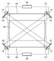
An outline of the coordinate input device according to the present embodiment will be described with reference to FIG. In the figure,
3A、3B、及び5A〜5Dは、再帰反射部材である。再帰反射部材は、入射光を到来方向に反射する再帰反射面を有することにより、それぞれのセンサユニットから投光された光を、センサユニットに向けて再帰的に反射する。再帰反射部材は、例えば入射した光を散乱する部材であってもよく、この場合にも入射した光は到来方向へと反射される。集光光学系及びラインCCD等によって構成されたセンサユニットの受光部によって、反射された光は1次元的に検出される。そして、検出された光量分布は制御ユニットに送られる。入力領域4Aは、座標を入力する入力領域であり、この入力領域上に位置する物体がセンサユニット1A〜1Dにより検出される。 3A, 3B, and 5A to 5D are retroreflective members. The retroreflective member has a retroreflective surface that reflects incident light in the direction of arrival, thereby recursively reflecting the light projected from each sensor unit toward the sensor unit. The retroreflective member may be a member that scatters incident light, for example, and in this case also, the incident light is reflected in the arrival direction. The reflected light is detected one-dimensionally by the light-receiving unit of the sensor unit that includes a condensing optical system and a line CCD. The detected light quantity distribution is sent to the control unit. The
本実施例において再帰反射部材は、入力領域を含む矩形領域の対向する二辺に配置される。一辺の再帰反射部材は、3A、5A、及び5Dに分割されて配置される。再帰反射部材5A,5Dは、一辺の再帰反射部材の両端部を構成し、再帰反射部材3Aは、再帰反射部材5A,5Dの間にある。対向する辺の再帰反射部材も同様に、3B、5B、及び5Cに分割されて配置される。再帰反射部材の分割部7A〜7Dにおいては、対向するセンサユニットから見て隙間が存在しないように、再帰反射部材が重なって配置される。例えば、センサユニット1B又は1Cから分割部7Aに対して光を投射する場合にも再帰反射光が帰ってくるように、分割部7Aにおいて再帰反射部材5A及び3Aは重なり合っている。 In the present embodiment, the retroreflective members are arranged on two opposite sides of a rectangular area including the input area. One side of the retroreflective member is divided into 3A, 5A, and 5D. The
再帰反射部材3A,3B(第2の部材)は不図示の筐体に取り付けられている。また、再帰反射部材5A〜5D(第1の部材)はそれぞれ、センサユニット1A〜1Dに搭載されている。再帰反射部材5A〜5Dは、反射面が入力領域の中心を向くように、再帰反射部材3A,3Bに対して傾けて配置されている。センサユニット1A及び1Dは、一方の辺に配置された再帰反射部材3B、5B、及び5Cに対して光を発射(投光)し、そして反射された光を受光する。同様にセンサユニット1B及び1Cは、他方の辺に配置された再帰反射部材3A、5A、及び5Dに対して投光し、そして反射された光を受光する。 The
本実施例においては、入力領域4Aは1面で構成される。そして、センサユニット1A〜1Dは、図2に示すように、入力領域4Aの外側に配置される。入力領域4AをPDPやリアプロジェクタ、LCDパネルなどの表示装置の表示画面としたり、又は入力領域4A上にフロントプロジェクタで画像を投影したりすることにより、入力領域4Aはインタラクティブな入力装置として利用可能となる。例えば入力領域4Aに指で触れるなど、物が入力領域4Aの直上に位置すると、センサユニット1A〜1Dの投光部から投光された光が遮られる。すると反射光がセンサユニット1A〜1Dの受光部に到達しなくなる。受光部は、光が入ってくる方向に対する光の強度分布を測定する。反射光が入ってこない角度を検出することにより、光を遮る物の位置、すなわち入力位置を判定することができる。 In this embodiment, the
制御ユニット2A及び2Bは、センサユニット1A〜1Dと双方向通信することが可能である。制御ユニット2A及び2Bは、センサユニット1A〜1Dの受光部による測定結果を用いて、入力位置の方向を特定する。そして制御ユニット2A及び2Bは協調して、特定された入力位置の方向およびセンサユニット1A〜1D間の距離等から、入力領域4Aにおける入力位置の座標位置を算出する(計算手段)。さらに制御ユニット2A及び2Bは、座標入力装置に接続されているPCなどに、USBなどのインタフェースを経由して座標位置を出力する。このようにして、指などで入力領域4Aに触れる、又は入力領域4Aの直上を動かすことによって、画面上に線を描画する、アイコンを選択するなど、PCを操作することなどが可能になる。 The
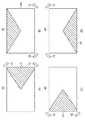
図11は、各センサユニット1A〜1Dが検出する入力位置の一例を示す。図11のように、センサユニット1C及び1Dを用いて、図11(A)の範囲91内への入力を検出するのがよい。また、センサユニット1B及び1Cを用いて、図11(B)範囲92内への入力を検出するのがよい。同様に、センサユニット1A及び1Bを用いて図11(C)の範囲93内への入力を、センサユニット1A及び1Dを用いて図11(D)の範囲94内への入力を、検出するのがよい。 FIG. 11 shows an example of input positions detected by the
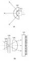
図3は、本実施例のセンサユニット1A〜1Dの投光部および受光部の一例を示す。図3(A)は、センサユニット1A〜1Dの投光部を示している。センサユニット1A〜1D中の投光部は、赤外LED101と、投光レンズ102とを備える。図3(A)において、101は、赤外光を発する赤外LEDであり、投光レンズ102によって、再帰反射部材3,5に向けて所定範囲に光を投光する。センサユニットの赤外LED101からの光束は、投光レンズ102により、入力領域に略平行となるように制限される。そしてこの制限された光束が、再帰反射部材3,5に対して投光される。 FIG. 3 shows an example of the light projecting section and the light receiving section of the
図3(B)は、センサユニット1A〜1Dの受光部を示している。センサユニット1A〜1Dの受光部は、1次元のラインCCD103と、集光光学系としての受光用レンズ104と、入射光の入射方向を概略制限する絞り105と、可視光等の余分な光(外乱光)の入射を防止する赤外フィルター106とを備える。 FIG. 3B shows the light receiving portions of the
投光部より投光された赤外光は、再帰反射部材3,5により到来方向に再帰的に反射される。そして、センサユニット1A〜1D中の受光部が、反射された光を検出する。より詳細には、再帰反射部材3,5によって反射された光は、赤外フィルター106、絞り105を通り、受光用レンズ104によってラインCCD103の検出素子面上に集光される。ラインCCD103は、反射光の入射角に応じた光量分布を示す信号を出力する。ラインCCD103を構成する各画素を、特定の角度から入射する反射光に対応させることにより、ラインCCD103から入射角に応じた光量分布を出力することができる。 The infrared light projected from the light projecting unit is recursively reflected in the arrival direction by the
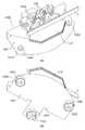
図1は、本実施例のセンサユニット1A〜1Dの詳細を示す。図1(A)は図2のセンサユニットの詳細な斜視図である。また、図1(B)は図1(A)に示されるF-Fの断面図である。図1において、図3と同一の部品は同一の符号が付されている。図1において、107は上フード部材、108は下フード部材である。上フード部材107と下フード部材108により、赤外フィルター106及び受光用レンズ104の位置が決定される。また、上フード部材107と下フード部材108とによって形成される隙間に、光束が入射する。 FIG. 1 shows details of the
本実施例において、投光部と受光部とが、入力領域4Aの面に対して垂直な方向に重ねられている。再帰反射部材5は、投光部と受光部との間に配置され、上フード部材107に取り付けられている。すなわち、投光部と受光部とのセットが、再帰反射部材を挟むように配置されている。係る構成により、再帰反射部材5が、投光部から投射される光を遮ることを防ぐことができる。 In the present embodiment, the light projecting unit and the light receiving unit are overlapped in a direction perpendicular to the surface of the
例えば、入力領域4A上に再帰反射部材5を配置する場合、再帰反射部材5と投光部との間に介在する部品の公差により、投射される光を遮る可能性がある。同様に、再帰反射部材5と受光部との間に介在する部品の公差により、反射された光を遮る可能性がある。したがって、入力領域4A上に再帰反射部材5を配置する場合には、再帰反射部材5の幅を縮小するか、又は、投光部と再帰反射部材5との間及び受光部と再帰反射部材5との間に隙間をあけることが好ましい。 For example, when the
しかしながら、再帰反射部材5の幅を縮小すると、反射面が小さくなり、受光部に入射する光量が減少する。また、投光部と再帰反射部材5との間、及び受光部と再帰反射部材5との間に隙間をあけると、投射された光線と受光する光線とのなす角度が大きくなるために、受光部に入射する光量が減少する。 However, when the width of the
本実施例の構成によれば、再帰反射部材5は上フード部材107に取り付けてられているので、投光部及び受光部と再帰反射部材5との間の位置の誤差(取り付け誤差)を最小とすることができる。したがって、再帰反射部材5の幅hを大きくすることができるし、投光部と受光部との間の距離Lをできるだけ小さくすることもできる。 According to the configuration of the present embodiment, since the
図10は、センサユニット1A〜1Dの構造と、入力検出性能との関係を示す。図10には、入力領域902と、再帰反射部材903と、センサユニットの投光部905と、センサユニットの受光部906と、入力領域に対して入力を行うペン又は指などの指示具907とが示されている。図10(A)〜(C)を通じて、指示具907と入力領域902との距離は一定である。指示具907が、投光部905から受光部906へ向かう光を遮光したときに、入力が検出される。 FIG. 10 shows the relationship between the structure of the
図10(C)は、本実施例に係るセンサユニット1A〜1Dの構造の一例を示す。本実施例においては、図10(C)で示されるように、投光部905と受光部906との間に再帰反射部材903が配置される。この場合、右側の投光部905aから受光部906aに向かう光が指示具907によって遮られる。また、左側の投光部905bから受光部906bに向かう光も指示具907によって遮られる。つまり、本実施例においては、受光部906aと受光部906bとの双方が指示具907の存在を検出することができるために、指示具907による入力位置を検出できる。 FIG. 10C illustrates an example of the structure of the
一方で、図10(A)のように再帰反射部材903の上部に投光部905及び受光部906が配置された場合、位置検出能力が低下する。すなわち図10(A)においては、左側の投光部905−2から受光部906−2へと向かう光は指示具907によって遮光されるが、右側の投光部905−1から受光部906−1へと向かう光は遮光されない。つまり図10(A)の構成においては、左側のセンサユニットは指示具907による入力位置を検出できるが、右側のセンサユニットは指示具907による入力位置を検出できない。すなわち、図10(A)の構成においては、指示具907が一方のセンサユニットに近接している場合、他方のセンサユニットの位置検出能力が低下する。 On the other hand, when the
また、図10(B)のように入力領域902と再帰反射部材903との間に投光部905及び受光部906を配置する場合にも、位置検出能力が低下する。すなわち図10(B)においては、右側の投光部905−1から受光部906−1へと向かう光は指示具907によって遮光されるが、左側の投光部905−2から受光部906−2へと向かう光は遮光されない。つまり図10(B)の構成においては、左側のセンサユニットは指示具907による入力位置を検出できるが、右側のセンサユニットは指示具907による入力位置を検出できない。すなわち、図10(B)の構成においても、指示具907が一方のセンサユニットに近接している場合、他方のセンサユニットの位置検出能力が低下する。以上のように、図10(A)及び(B)に示した構成においては、指示具907が入力領域902から離れている場合に、位置を検出する能力が低下してしまう。 Further, when the
以上のように本実施例においては、再帰反射部材5が存在する位置に、投光部及び受光部を備えるセンサユニットを配置するにもかかわらず、センサユニット近傍での位置検出能力が低下しない。本実施例では入力領域4Aに近い側から受光部、再帰反射部材5、投光部を順番に配置した。しかしながら、投光部と受光部との配置を逆にすることもできる。本実施例においては再帰反射部材3A,3Bと再帰反射部材5A〜5Dとが分割されて配置されたが、再帰反射部材は分割されていなくてもよい。センサユニットは、対向する二辺に沿って配置された再帰反射部材のそれぞれについて、少なくとも2カ所に配置されていればよい。 As described above, in the present embodiment, the position detection capability in the vicinity of the sensor unit does not deteriorate even though the sensor unit including the light projecting unit and the light receiving unit is disposed at the position where the
[実施例2]
実施例1において、センサユニット1は、投光部と、受光部と、再帰反射部材5とによって構成され、再帰反射部材は投光部と受光部との間に配置された。本実施例のセンサユニット1は、さらなる再帰反射部材8又は9を備える。本実施例のセンサユニット1の一例が、図4及び図5に示される。図4及び図5において、実施例1と同様の構成部品は、実施例1と同じ参照番号で示されている。[Example 2]
In Example 1, the sensor unit 1 includes a light projecting unit, a light receiving unit, and a
図4に示すセンサユニット1には、実施例1のセンサユニット1と比べて、再帰反射部材5と同様の再帰反射部材8が追加されている。図4において、投光部101〜102から出る光の光路は再帰反射部材5と再帰反射部材8とで挟まれている。また、図5に示すセンサユニット1には、実施例1のセンサユニット1と比べて、再帰反射部材5と同様の再帰反射部材9が追加されている。図5において、受光部103〜106に入る光の光路は再帰反射部材5と再帰反射部材8とで挟まれている。 In the sensor unit 1 shown in FIG. 4, a
本実施例のように、さらなる再帰反射部材8又は9を備えることにより、再帰反射面の面積を増やすことができる。したがって本実施例においては、投光部と受光部との間に位置する再帰反射部材5の幅を実施例1と比べて半分にしても、再帰反射面と同じ幅を持つ再帰反射部材8又は9を用いることにより、全体の反射面の面積を実施例1と同程度とすることができる。 By providing the further
例えば図4において、再帰反射部材8は幅h/2を有し、上フード部材107のリブ部材1071、1702に取り付けられている。また再帰反射部材8は、投光部よりも入力領域4Aから遠い位置に位置するように、前記センサユニットに一体的に搭載されている。再帰反射部材5も同様に幅h/2を有する。この構成により、再帰反射部材5が幅hを有する実施例1の構成と、同程度の反射面積を有することができる。一方で図4の構成においては、再帰反射部材5の幅が小さくなるために、投光部と受光部との間の距離Lを短くすることができる。したがって、投光部から発せられ、再帰反射部材で反射された光を、受光部が検出することが、実施例1よりも容易となる。 For example, in FIG. 4, the
図5においては、再帰反射部材9は下フード部材108に取り付けられている。また再帰反射部材9は、投光部よりも入力領域4Aに近い位置に位置するように、前記センサユニットに一体的に搭載されている。この構成においても同様に、再帰反射部材5及び再帰反射部材8の幅はh/2でもよく、光の検出も実施例1より容易となる。本実施例では、再帰反射部材5と、再帰反射部材8又は9の幅の比を、0.5:0.5として説明した。しかしながら、この比率は適宜変更することができる。 In FIG. 5, the retroreflective member 9 is attached to the
[実施例3]
実施例1では、4つのセンサユニットを用いる座標入力装置を説明した。本実施例では、より多くのセンサユニットを用いることにより、実施例1と比べて広い入力領域を有する座標入力装置について説明する。図6は、本実施例に係る構成の一例を示す図である。図6において、実施例1と同様の構成部品は、実施例1と同じ参照番号で示されている。[Example 3]
In the first embodiment, a coordinate input device using four sensor units has been described. In the present embodiment, a coordinate input device having a wider input area than that of the first embodiment by using more sensor units will be described. FIG. 6 is a diagram illustrating an example of a configuration according to the present embodiment. In FIG. 6, the same components as those of the first embodiment are denoted by the same reference numerals as those of the first embodiment.
1A〜1Dおよび1E〜1Hは投光部および受光部を有するセンサユニットである。それぞれのセンサユニット1A〜1Hは、実施例1と同様の動作を行う制御ユニット2A〜2Dに接続されている。本実施例の座標入力装置は、隣接する入力領域4A及び4Bを備える。本実施例の座標入力装置は、4つのセンサユニット1A〜1Dを用いて入力領域4Aへの入力を検知し、4つのセンサユニット1E〜1Hを用いて入力領域4Bへの入力を検知する。図6において、センサユニット1A〜1Hは、入力領域4A,4Bの外側に配置されている。 1A to 1D and 1E to 1H are sensor units having a light projecting unit and a light receiving unit. Each of the
301A〜306A、301B〜302B、および5A〜5Dは、実施例1と同様の再帰反射部材である。以降では、再帰反射部材5A〜5Dを第1の再帰反射部材と呼ぶ。また、再帰反射部材301A〜306A及び301B〜302Bを第2の再帰反射部材と呼ぶ。本実施例において、第1の再帰反射部材はセンサユニット1A〜1Dに搭載されている。また、第2の再帰反射部材は座標入力装置の筐体(不図示)に取り付けられている。
本実施例において、第1及び第2の再帰反射部材は、入力領域4A,4Bの対向する二辺に配置されている。すなわち、第1の再帰反射部材5A,5D,5E,5H及び第2の再帰反射部材301A〜306Aが一辺に位置し、第1の再帰反射部材5B,5C,5F,5G及び第2の再帰反射部材301B〜306Bが他方の辺に位置する。 In the present embodiment, the first and second retroreflective members are arranged on two opposite sides of the
一辺に位置する第1及び第2の再帰反射部材は、他方の辺に位置するセンサユニットから見て、隙間が存在しないように配置されていることが好ましい。例えば、一辺に位置するセンサユニットが、他辺に向けて光を照射する場合に、常に再帰反射部材からの反射光が帰ってくることが好ましい。このために本実施例において、再帰反射部材5C及び5Dは、再帰反射部材5E及び5Fよりも長くなっている。しかしながら、再帰反射部材5E及び5Fの長さが、再帰反射部材5C及び5Dの長さよりも長くてもよい。 The first and second retroreflective members located on one side are preferably arranged so that there is no gap when viewed from the sensor unit located on the other side. For example, when the sensor unit located on one side irradiates light toward the other side, it is preferable that reflected light from the retroreflective member always returns. Therefore, in this embodiment, the
本実施例において、センサユニット1A及び1Dは、第1の再帰反射部材5B、5C、及び5F、並びに第2の再帰反射部材301B〜304Bに対して光を投光し、反射された光を受光する。センサユニット1B及び1Cは、第1の再帰反射部材5A、5D、及び5E、並びに第2の再帰反射部材301A〜304Aに対して光を投光し、反射された光を受光する。 In the present embodiment, the
同様にセンサユニット1E及び1Hは、第1の再帰反射部材5C、5F、及び5G、並びに第2の再帰反射部材303B〜306Bに対して光を投光し、反射された光を受光する。またセンサユニット1F及び1Gは、第1の再帰反射部材5D、5E、及び5H、並びに第2の再帰反射部材303A〜306Aに対して光を投光し、反射された光を受光する。 Similarly, the
本実施例を応用することにより、さらに広い入力領域を備える座標入力装置を構成することもできる。例えば、センサユニット1C〜1F、第1の再帰反射部材5C〜5F、並びに第2の再帰反射部材302A〜304A及び302B〜304Bを含む構造を繰り返し配置すればよい。以上の本実施例に係る構成によれば、実施例1のような4つのセンサユニットを備える座標入力装置よりも広い入力領域を備える、大型の座標入力装置を実現することができる。 By applying this embodiment, a coordinate input device having a wider input area can be configured. For example, a structure including the
[実施例4]
本実施例では、実施例3において隣接するセンサユニット間(第1の再帰反射部材間)に、さらなる第2の反射部材を追加する。図12は、本実施例に係る構成の一例を示す図である。図12において、実施例3と同様の構成部品は、実施例3と同じ参照番号で示されている。図12の座標入力装置は、座標入力装置の筐体(不図示)に取り付けられた第2の再帰反射部材6A及び6Bを備える。第2の再帰反射部材6Aは、第1の再帰反射部材5Dと第1の再帰反射部材5Eとの間に配置されている。また第2の再帰反射部材6Bは、第1の再帰反射部材5Dと第1の再帰反射部材5Eとの間に配置されている。[Example 4]
In the present embodiment, a further second reflecting member is added between the adjacent sensor units in the third embodiment (between the first retroreflective members). FIG. 12 is a diagram illustrating an example of a configuration according to the present embodiment. In FIG. 12, the same components as those of the third embodiment are denoted by the same reference numerals as those of the third embodiment. The coordinate input device of FIG. 12 includes second
本実施例においても、対向する辺に位置するセンサユニット1B,1C,1F,1Gから見て、第1の再帰反射部材5Dと、第1の再帰反射部材5Eと、第2の再帰反射部材6Aとは、隙間を生じないように重なっている。同様に、対向する辺に位置するセンサユニット1A,1D,1E,1Hから見て、第1の再帰反射部材5Cと、第1の再帰反射部材5Fと、第2の再帰反射部材6Bとは、隙間を生じないように重なり合っている。本実施例によれば、センサユニット間に配置された第2の再帰反射部材6A及び6Bを用いることにより、センサユニットに搭載された第1の再帰反射部材の長さを、実施例3よりも短くすることができる。 Also in the present embodiment, the first
[実施例5]
実施例1では、センサユニット1を座標入力装置に固定したが、本実施例では、センサユニット1の姿勢を調整可能とする。センサユニット1を座標入力装置に取り付ける際に取り付け誤差が生じた場合、受光部に入る光量が少なくなる。取り付け誤差を小さくするためには部品公差を厳しくする必要があり、これは高いコストにつながり、量産を難しくする。センサユニットの姿勢を調整可能とすることにより、受光部に入る光量が多くなるように調整を行うことができる。[Example 5]
In the first embodiment, the sensor unit 1 is fixed to the coordinate input device, but in this embodiment, the posture of the sensor unit 1 can be adjusted. If an attachment error occurs when the sensor unit 1 is attached to the coordinate input device, the amount of light entering the light receiving portion is reduced. In order to reduce the mounting error, it is necessary to tighten part tolerances, which leads to high costs and makes mass production difficult. By making the posture of the sensor unit adjustable, adjustment can be performed so that the amount of light entering the light receiving unit increases.
図7は、本実施例に係る姿勢調整ユニット1000の一例を示す。実施例1と同様の構成部品は、同じ参照番号で示されている。姿勢調整ユニット1000は、座標入力装置の筐体(不図示)に取り付けられている。実施例1でも述べたように、第1の再帰反射部材5は、センサユニットの上フード部材107に取り付けられている。 FIG. 7 shows an example of the
取り付け部材1001は、コの字状の板金である。姿勢調整ネジ1002,1003,1004は、取り付け部材1001の貫通穴(不図示)を通して、座標入力装置の筐体のネジ穴(不図示)に螺合される。圧縮バネ1005,1006,1007は、取り付け部材1001と座標入力装置の筐体(不図示)とに挟まれている。 The
姿勢調整ネジ1002,1003,1004を調整することにより、圧縮バネ1005,1006,1007を介した、取り付け部材1001と座標入力装置の筐体(不図示)との間の距離を調整することができる。したがって、取り付け部材1001を介して、座標入力装置の筐体(不図示)に対する、センサユニット1の姿勢を調整することができる。 By adjusting the
図8(A)〜(C)は本実施例に係るセンサユニットの断面図である。また図8(D)〜(F)は、再帰反射部材5を座標入力装置の筐体(不図示)に固定した場合の、センサユニットの断面図である。図8(A)及び(D)はセンサユニットの姿勢を調整していない場合を示す。一方、図8(B)及び(E)は、矢印の方向にセンサユニットの姿勢を調整した場合を示す。本実施例においては、センサユニット1に再帰反射部材5を搭載しているため、第1の再帰反射部材5はセンサユニットと一体的に動く。従って図8(B)に示されるように、センサユニットの姿勢を調整した後でも、再帰反射部材5は投光部からの光を遮らない。一方で図8(E)の構成では、センサユニットの姿勢を調整すると、投光部からの光は再帰反射部材5によって遮られる。 8A to 8C are cross-sectional views of the sensor unit according to the present embodiment. 8D to 8F are cross-sectional views of the sensor unit when the
図8(C)及び(E)も同様に、矢印の方向にセンサユニットの姿勢を調整した場合を示す。この場合にも、図8(C)に示される本実施例の構成によれば、受光部に入る光は再帰反射部材5によって遮られない。一方で図8(F)の構成では、センサユニットの姿勢を調整すると、受光部への光は再帰反射部材5によって遮られる。以上のように、再帰反射部材5を投光部及び受光部と一体的に構成することによって、センサユニットの位置を調整しても、再帰反射部材5は光を遮らない。 Similarly, FIGS. 8C and 8E show a case where the posture of the sensor unit is adjusted in the direction of the arrow. Also in this case, according to the configuration of the present embodiment shown in FIG. 8C, the light entering the light receiving unit is not blocked by the
[実施例6]
以上の各実施例の座標入力装置において、第1の再帰反射部材5の幅を大きくすると、投光部と受光部との間隔が大きくなる。したがって投光部からの光線と受光部への光線とのなす角度が大きくなるため、受光光量が減少する。一方で、第1の再帰反射部材5の幅を小さくすると、第1の再帰反射部材5によって反射される光の光量は少なくなる。したがって、最適な第1の再帰反射部材5の幅が存在する。しかしながら、最適な再帰反射部材5の幅は、通常は第2の再帰反射部材3Aよりも細くなる。[Example 6]
In the coordinate input device of each of the embodiments described above, when the width of the first
したがって、第1の再帰反射部材によって反射される光の光量は、第2の再帰反射部材3Aによって反射される光の光量よりも小さくなる。第1の再帰反射部材5によって反射される光の光量を増やすために、本実施例においては、第1の再帰反射部材5として高反射率の再帰反射部材を使用する。これによって、第1の再帰反射部材5によって反射される光の光量を増やすことができる。 Therefore, the amount of light reflected by the first retroreflective member is smaller than the amount of light reflected by the
[実施例7]
実施例1のセンサユニット1は、入力領域4Aに近い側から受光部、再帰反射部材5、投光部が順番に位置するように構成されていた。本実施例のセンサユニット1は、さらなる投光部を備える。本実施例に係るセンサユニットの一例を、図13に示す。実施例1と同様の構成部品は、同じ参照番号で示されている。[Example 7]
The sensor unit 1 of Example 1 is configured such that the light receiving unit, the
図13のセンサユニット1は、入力領域4Aに近い側から、赤外LED101Aと投光レンズ102Aとを備える投光部、受光部、再帰反射部材5、赤外LED101Bと投光レンズ102Bとを備える投光部、を順番に備える。本実施例のセンサユニット1は2つの投光部を有するために、実施例1と比べて投光量を2倍にすることができる。この結果、実施例1と比べて受光光量を増やすことができる。 The sensor unit 1 of FIG. 13 includes a light projecting unit including an
[実施例8]
図14は、本実施例に係る座標入力装置の構成の一例を示す図である。本実施例に係る座標入力装置は、実施例1と比較して、図2に示される再帰反射部材3A、3Bの配置が変更されている。本実施例に係る座標入力装置は、複数台を結合することが可能である。複数台の座標入力装置を結合することにより、より広い入力領域を実現することができる。一例として図15には、本実施例に係る座標入力装置を2台結合させた様子が表されている。図14において、実施例1と同様の構成部品は、実施例1と同じ参照番号で示されている。[Example 8]
FIG. 14 is a diagram illustrating an example of the configuration of the coordinate input device according to the present embodiment. In the coordinate input device according to the present embodiment, the arrangement of the
図14の座標入力装置は、座標入力装置の筐体(不図示)に取り付けられた再帰反射部材3K及び3Lを、センサユニット1A及び1Dと、センサユニット1B及び1Cと、のそれぞれの外側に備える。図15に示すように、本実施例の座標入力装置を2つ並べたときに、一方の座標入力装置の再帰反射部材3Kは、他方の座標入力装置の再帰反射部材5A又は5Dの裏側にまで達する。ここで裏側とは、入力領域から離れた側を指す。また、本実施例の座標入力装置を2つ並べたときに、一方の座標入力装置の再帰反射部材3Lは、他方の座標入力装置の再帰反射部材5B又は5Cの裏側にまで達する。 The coordinate input device of FIG. 14 includes
本実施例において、対向する辺に位置するセンサユニット1B,1Cから見て、再帰反射部材5Aと、再帰反射部材5Dと、再帰反射部材3Kとは、隙間を生じないように重なっている。同様に、対向する辺に位置するセンサユニット1A,1Dから見て、再帰反射部材5Bと、第1の再帰反射部材5Cと、再帰反射部材3Lとは、隙間を生じないように重なり合っている。この結果、本実施例の座標入力装置を2つ並べることによって、入力領域に隙間が生じないマルチ座標入力装置を構成することができる。 In the present embodiment, the
実施例1〜7に係る座標入力装置は、入力領域を含む矩形領域の対向する二辺に再帰反射部材を持てばよい。したがって、再帰反射部材が隙間なく連続するように座標入力装置を連結することにより、実施例8に示したように大きな入力領域を実現することができる。 The coordinate input devices according to Examples 1 to 7 may have retroreflective members on two opposite sides of a rectangular area including the input area. Therefore, by connecting the coordinate input device so that the retroreflective members are continuous without a gap, a large input area can be realized as shown in the eighth embodiment.
1A〜1D センサユニット
3A,3B,3K,3L,5A〜5D 再帰反射部材
4A 入力領域
101 赤外LED
102 投光レンズ
103 ラインCCD
104 受光用レンズ
105 絞り
106 赤外フィルター
107 上フード部材
108 下フード部材1A to
102
104 Light-receiving
Claims (3)
Translated fromJapanese前記入力領域に向けて光を発射する投光部と、
前記入力領域を含む矩形領域の対向する二辺に沿って配置され、前記投光部が発射した光を反射する反射面を有する、再帰反射部材と、
前記投光部から発射されて前記再帰反射部材の反射面で反射した光を受光し、当該受光した光の強度を測定する受光部と、
前記受光部の測定結果から、前記物体の位置を求める計算手段と、を備え、
前記入力領域の面に対して垂直な方向に前記再帰反射部材を挟むように、前記再帰反射部材に隣接して配置された前記投光部と前記受光部とのセットが、前記対向する二辺に配置された前記再帰反射部材のそれぞれの少なくとも2か所に位置する
ことを特徴とする、座標入力装置。A coordinate input device for calculating the position of an object located on an input area,
A light projecting unit that emits light toward the input area;
A retroreflective member that is disposed along two opposing sides of a rectangular region including the input region and has a reflecting surface that reflects the light emitted by the light projecting unit;
A light receiving unit that receives the light emitted from the light projecting unit and reflected by the reflecting surface of the retroreflective member, and measures the intensity of the received light;
Calculating means for obtaining the position of the object from the measurement result of the light receiving unit,
A set of the light projecting unit and the light receiving unit arranged adjacent to the retroreflective member so as to sandwich the retroreflective member in a direction perpendicular to the surface of the input region is the two opposite sides The coordinate input device is located at at least two positions of each of the retroreflective members disposed on the surface.
前記2つの第1の部材のそれぞれには、前記投光部と前記受光部とのセットが位置しており、
前記2つの第1の部材のそれぞれが有する反射面が前記入力領域の中心を向くように、前記2つの第1の部材のそれぞれは配置されていることを特徴とする、請求項1に記載の座標入力装置。Each of the retroreflective members disposed along the two opposing sides includes two first members constituting both ends, and a second member between the two first members,
Each of the two first members has a set of the light projecting unit and the light receiving unit,
2. Each of the two first members is arranged such that a reflection surface of each of the two first members faces the center of the input region. Coordinate input device.
前記第1の部材が有する反射面の反射率は、前記第2の部材が有する反射面の反射率よりも高いことを特徴とする、請求項2に記載の座標入力装置。The reflective surface of the first member is shorter in the direction perpendicular to the surface of the input region than the reflective surface of the second member,
The coordinate input device according to claim 2, wherein the reflectance of the reflecting surface of the first member is higher than the reflectance of the reflecting surface of the second member.
Priority Applications (2)
| Application Number | Priority Date | Filing Date | Title |
|---|---|---|---|
| JP2010136650AJP5451538B2 (en) | 2010-06-15 | 2010-06-15 | Coordinate input device |
| US13/155,372US9063618B2 (en) | 2010-06-15 | 2011-06-07 | Coordinate input apparatus |
Applications Claiming Priority (1)
| Application Number | Priority Date | Filing Date | Title |
|---|---|---|---|
| JP2010136650AJP5451538B2 (en) | 2010-06-15 | 2010-06-15 | Coordinate input device |
Publications (2)
| Publication Number | Publication Date |
|---|---|
| JP2012003434A JP2012003434A (en) | 2012-01-05 |
| JP5451538B2true JP5451538B2 (en) | 2014-03-26 |
Family
ID=45095837
Family Applications (1)
| Application Number | Title | Priority Date | Filing Date |
|---|---|---|---|
| JP2010136650AExpired - Fee RelatedJP5451538B2 (en) | 2010-06-15 | 2010-06-15 | Coordinate input device |
Country Status (2)
| Country | Link |
|---|---|
| US (1) | US9063618B2 (en) |
| JP (1) | JP5451538B2 (en) |
Families Citing this family (9)
| Publication number | Priority date | Publication date | Assignee | Title |
|---|---|---|---|---|
| JP5591069B2 (en)* | 2010-11-04 | 2014-09-17 | キヤノン株式会社 | Coordinate input device, control method therefor, and program |
| JP5973849B2 (en) | 2012-03-08 | 2016-08-23 | キヤノン株式会社 | Coordinate input device and sensor bar used for coordinate input device |
| JP5875445B2 (en) | 2012-03-30 | 2016-03-02 | キヤノン株式会社 | Coordinate input device |
| US9507462B2 (en)* | 2012-06-13 | 2016-11-29 | Hong Kong Applied Science and Technology Research Institute Company Limited | Multi-dimensional image detection apparatus |
| JP6031293B2 (en)* | 2012-08-03 | 2016-11-24 | キヤノン株式会社 | Coordinate input device, control method therefor, and program |
| JP6021531B2 (en) | 2012-08-31 | 2016-11-09 | キヤノン株式会社 | Coordinate input device, control method therefor, and program |
| JP6241198B2 (en) | 2012-12-07 | 2017-12-06 | 株式会社リコー | Coordinate detection device and electronic information board system |
| US9189081B2 (en)* | 2012-12-17 | 2015-11-17 | Eminent Electronic Technology Corp. Ltd. | Optical sensing apparatus and method for detecting object near optical sensing apparatus |
| JP6273775B2 (en) | 2013-10-31 | 2018-02-07 | セイコーエプソン株式会社 | Light emitting device and image display system |
Family Cites Families (10)
| Publication number | Priority date | Publication date | Assignee | Title |
|---|---|---|---|---|
| JPH04118664A (en) | 1990-09-10 | 1992-04-20 | Seiko Epson Corp | Production of magnetic toner |
| US5764223A (en)* | 1995-06-07 | 1998-06-09 | International Business Machines Corporation | Touch-screen input device using the monitor as a light source operating at an intermediate frequency |
| US6480187B1 (en)* | 1997-08-07 | 2002-11-12 | Fujitsu Limited | Optical scanning-type touch panel |
| US6335724B1 (en)* | 1999-01-29 | 2002-01-01 | Ricoh Company, Ltd. | Method and device for inputting coordinate-position and a display board system |
| JP4083941B2 (en)* | 1999-09-03 | 2008-04-30 | 株式会社リコー | Coordinate input device |
| JP4118664B2 (en)* | 2002-12-06 | 2008-07-16 | リコーエレメックス株式会社 | Coordinate detection device |
| US7232986B2 (en)* | 2004-02-17 | 2007-06-19 | Smart Technologies Inc. | Apparatus for detecting a pointer within a region of interest |
| US20090309853A1 (en)* | 2008-06-13 | 2009-12-17 | Polyvision Corporation | Electronic whiteboard system and assembly with optical detection elements |
| TWI420357B (en)* | 2009-08-28 | 2013-12-21 | Pixart Imaging Inc | Touch system and pointer coordinate detecting method therefor |
| US20110128218A1 (en)* | 2009-12-01 | 2011-06-02 | Smart Technologies Ulc | Interactive input system and bezel therefor |
- 2010
- 2010-06-15JPJP2010136650Apatent/JP5451538B2/ennot_activeExpired - Fee Related
- 2011
- 2011-06-07USUS13/155,372patent/US9063618B2/ennot_activeExpired - Fee Related
Also Published As
| Publication number | Publication date |
|---|---|
| US20110304535A1 (en) | 2011-12-15 |
| JP2012003434A (en) | 2012-01-05 |
| US9063618B2 (en) | 2015-06-23 |
Similar Documents
| Publication | Publication Date | Title |
|---|---|---|
| JP5451538B2 (en) | Coordinate input device | |
| EP1331594B1 (en) | Optical scanning touch panel | |
| US7689381B2 (en) | Sensing system | |
| JP3830121B2 (en) | Optical unit for object detection and position coordinate input device using the same | |
| KR20080044017A (en) | touch screen | |
| JP5725774B2 (en) | Coordinate input device and coordinate input method | |
| US20110019204A1 (en) | Optical and Illumination Techniques for Position Sensing Systems | |
| US8922526B2 (en) | Touch detection apparatus and touch point detection method | |
| EP1574939A1 (en) | Coordinate input apparatus, its control method, and program | |
| KR20120112466A (en) | Apparatus and method for receiving a touch input | |
| JP2001265516A (en) | Coordinate input device | |
| JP2022063376A (en) | Aerial display device | |
| JP2012173138A (en) | Optical position detection device | |
| JP4034328B2 (en) | Luminescence detection device and coordinate detection device | |
| JP4531081B2 (en) | Optical scanning touch panel | |
| US8232511B2 (en) | Sensing system adapted to sense a pointer and calculate a location of the pointer | |
| JP2002007051A (en) | Optical digitizer | |
| CN117837138A (en) | Space suspension image information display system and three-dimensional sensing device used by same | |
| TWI471785B (en) | Optical touch module | |
| JP2004139288A (en) | Optical coordinate input device | |
| US9189106B2 (en) | Optical touch panel system and positioning method thereof | |
| JP2004157708A (en) | Coordinate input device | |
| JP4183327B2 (en) | Optical scanning touch panel | |
| JP2007280433A (en) | Optical scanning touch panel | |
| WO2024079832A1 (en) | Interface device |
Legal Events
| Date | Code | Title | Description |
|---|---|---|---|
| A621 | Written request for application examination | Free format text:JAPANESE INTERMEDIATE CODE: A621 Effective date:20130611 | |
| TRDD | Decision of grant or rejection written | ||
| A977 | Report on retrieval | Free format text:JAPANESE INTERMEDIATE CODE: A971007 Effective date:20131127 | |
| A01 | Written decision to grant a patent or to grant a registration (utility model) | Free format text:JAPANESE INTERMEDIATE CODE: A01 Effective date:20131202 | |
| A61 | First payment of annual fees (during grant procedure) | Free format text:JAPANESE INTERMEDIATE CODE: A61 Effective date:20131226 | |
| R151 | Written notification of patent or utility model registration | Ref document number:5451538 Country of ref document:JP Free format text:JAPANESE INTERMEDIATE CODE: R151 | |
| LAPS | Cancellation because of no payment of annual fees |