JP5450128B2 - Power supply device and vehicle equipped with the same - Google Patents
Power supply device and vehicle equipped with the sameDownload PDFInfo
- Publication number
- JP5450128B2 JP5450128B2JP2010017492AJP2010017492AJP5450128B2JP 5450128 B2JP5450128 B2JP 5450128B2JP 2010017492 AJP2010017492 AJP 2010017492AJP 2010017492 AJP2010017492 AJP 2010017492AJP 5450128 B2JP5450128 B2JP 5450128B2
- Authority
- JP
- Japan
- Prior art keywords
- power supply
- battery
- supply device
- temperature equalizing
- equalizing plate
- Prior art date
- Legal status (The legal status is an assumption and is not a legal conclusion. Google has not performed a legal analysis and makes no representation as to the accuracy of the status listed.)
- Active
Links
- 239000000112cooling gasSubstances0.000claimsdescription80
- 238000001816coolingMethods0.000claimsdescription79
- 238000003780insertionMethods0.000claimsdescription53
- 230000037431insertionEffects0.000claimsdescription53
- 238000007664blowingMethods0.000claimsdescription23
- 210000000078clawAnatomy0.000claimsdescription20
- 229910052751metalInorganic materials0.000claimsdescription17
- 239000002184metalSubstances0.000claimsdescription17
- 239000000463materialSubstances0.000claimsdescription14
- 230000007423decreaseEffects0.000claimsdescription5
- 238000005452bendingMethods0.000claimsdescription2
- 238000010030laminatingMethods0.000claims1
- 230000007246mechanismEffects0.000description9
- 230000008901benefitEffects0.000description8
- 230000000903blocking effectEffects0.000description7
- 230000006866deteriorationEffects0.000description5
- 230000000694effectsEffects0.000description5
- 238000000034methodMethods0.000description5
- 238000004519manufacturing processMethods0.000description4
- 230000008859changeEffects0.000description3
- 230000004048modificationEffects0.000description3
- 238000012986modificationMethods0.000description3
- 238000000465mouldingMethods0.000description3
- 238000003466weldingMethods0.000description3
- 238000010586diagramMethods0.000description2
- 238000007599dischargingMethods0.000description2
- 239000011810insulating materialSubstances0.000description2
- 230000000149penetrating effectEffects0.000description2
- 239000003507refrigerantSubstances0.000description2
- 230000003014reinforcing effectEffects0.000description2
- 239000011347resinSubstances0.000description2
- 229920005989resinPolymers0.000description2
- 238000002791soakingMethods0.000description2
- 125000006850spacer groupChemical group0.000description2
- 230000035882stressEffects0.000description2
- HBBGRARXTFLTSG-UHFFFAOYSA-NLithium ionChemical group[Li+]HBBGRARXTFLTSG-UHFFFAOYSA-N0.000description1
- 230000001133accelerationEffects0.000description1
- 230000032683agingEffects0.000description1
- 229910052782aluminiumInorganic materials0.000description1
- XAGFODPZIPBFFR-UHFFFAOYSA-NaluminiumChemical compound[Al]XAGFODPZIPBFFR-UHFFFAOYSA-N0.000description1
- OJIJEKBXJYRIBZ-UHFFFAOYSA-Ncadmium nickelChemical compound[Ni].[Cd]OJIJEKBXJYRIBZ-UHFFFAOYSA-N0.000description1
- 239000000470constituentSubstances0.000description1
- 239000007789gasSubstances0.000description1
- 229920006015heat resistant resinPolymers0.000description1
- 238000009413insulationMethods0.000description1
- 238000003475laminationMethods0.000description1
- 229910001416lithium ionInorganic materials0.000description1
- 230000013011matingEffects0.000description1
- 229910052987metal hydrideInorganic materials0.000description1
- 229910052759nickelInorganic materials0.000description1
- PXHVJJICTQNCMI-UHFFFAOYSA-NnickelSubstances[Ni]PXHVJJICTQNCMI-UHFFFAOYSA-N0.000description1
- -1nickel metal hydrideChemical class0.000description1
- 230000008569processEffects0.000description1
- 230000009467reductionEffects0.000description1
- 230000001172regenerating effectEffects0.000description1
- 238000004904shorteningMethods0.000description1
Images


Classifications
- H—ELECTRICITY
- H01—ELECTRIC ELEMENTS
- H01M—PROCESSES OR MEANS, e.g. BATTERIES, FOR THE DIRECT CONVERSION OF CHEMICAL ENERGY INTO ELECTRICAL ENERGY
- H01M10/00—Secondary cells; Manufacture thereof
- H01M10/60—Heating or cooling; Temperature control
- H01M10/61—Types of temperature control
- H01M10/617—Types of temperature control for achieving uniformity or desired distribution of temperature
- B—PERFORMING OPERATIONS; TRANSPORTING
- B60—VEHICLES IN GENERAL
- B60L—PROPULSION OF ELECTRICALLY-PROPELLED VEHICLES; SUPPLYING ELECTRIC POWER FOR AUXILIARY EQUIPMENT OF ELECTRICALLY-PROPELLED VEHICLES; ELECTRODYNAMIC BRAKE SYSTEMS FOR VEHICLES IN GENERAL; MAGNETIC SUSPENSION OR LEVITATION FOR VEHICLES; MONITORING OPERATING VARIABLES OF ELECTRICALLY-PROPELLED VEHICLES; ELECTRIC SAFETY DEVICES FOR ELECTRICALLY-PROPELLED VEHICLES
- B60L3/00—Electric devices on electrically-propelled vehicles for safety purposes; Monitoring operating variables, e.g. speed, deceleration or energy consumption
- B60L3/0023—Detecting, eliminating, remedying or compensating for drive train abnormalities, e.g. failures within the drive train
- B60L3/0046—Detecting, eliminating, remedying or compensating for drive train abnormalities, e.g. failures within the drive train relating to electric energy storage systems, e.g. batteries or capacitors
- B—PERFORMING OPERATIONS; TRANSPORTING
- B60—VEHICLES IN GENERAL
- B60L—PROPULSION OF ELECTRICALLY-PROPELLED VEHICLES; SUPPLYING ELECTRIC POWER FOR AUXILIARY EQUIPMENT OF ELECTRICALLY-PROPELLED VEHICLES; ELECTRODYNAMIC BRAKE SYSTEMS FOR VEHICLES IN GENERAL; MAGNETIC SUSPENSION OR LEVITATION FOR VEHICLES; MONITORING OPERATING VARIABLES OF ELECTRICALLY-PROPELLED VEHICLES; ELECTRIC SAFETY DEVICES FOR ELECTRICALLY-PROPELLED VEHICLES
- B60L50/00—Electric propulsion with power supplied within the vehicle
- B60L50/50—Electric propulsion with power supplied within the vehicle using propulsion power supplied by batteries or fuel cells
- B60L50/60—Electric propulsion with power supplied within the vehicle using propulsion power supplied by batteries or fuel cells using power supplied by batteries
- B60L50/64—Constructional details of batteries specially adapted for electric vehicles
- B—PERFORMING OPERATIONS; TRANSPORTING
- B60—VEHICLES IN GENERAL
- B60L—PROPULSION OF ELECTRICALLY-PROPELLED VEHICLES; SUPPLYING ELECTRIC POWER FOR AUXILIARY EQUIPMENT OF ELECTRICALLY-PROPELLED VEHICLES; ELECTRODYNAMIC BRAKE SYSTEMS FOR VEHICLES IN GENERAL; MAGNETIC SUSPENSION OR LEVITATION FOR VEHICLES; MONITORING OPERATING VARIABLES OF ELECTRICALLY-PROPELLED VEHICLES; ELECTRIC SAFETY DEVICES FOR ELECTRICALLY-PROPELLED VEHICLES
- B60L58/00—Methods or circuit arrangements for monitoring or controlling batteries or fuel cells, specially adapted for electric vehicles
- B60L58/10—Methods or circuit arrangements for monitoring or controlling batteries or fuel cells, specially adapted for electric vehicles for monitoring or controlling batteries
- B60L58/18—Methods or circuit arrangements for monitoring or controlling batteries or fuel cells, specially adapted for electric vehicles for monitoring or controlling batteries of two or more battery modules
- B—PERFORMING OPERATIONS; TRANSPORTING
- B60—VEHICLES IN GENERAL
- B60L—PROPULSION OF ELECTRICALLY-PROPELLED VEHICLES; SUPPLYING ELECTRIC POWER FOR AUXILIARY EQUIPMENT OF ELECTRICALLY-PROPELLED VEHICLES; ELECTRODYNAMIC BRAKE SYSTEMS FOR VEHICLES IN GENERAL; MAGNETIC SUSPENSION OR LEVITATION FOR VEHICLES; MONITORING OPERATING VARIABLES OF ELECTRICALLY-PROPELLED VEHICLES; ELECTRIC SAFETY DEVICES FOR ELECTRICALLY-PROPELLED VEHICLES
- B60L58/00—Methods or circuit arrangements for monitoring or controlling batteries or fuel cells, specially adapted for electric vehicles
- B60L58/10—Methods or circuit arrangements for monitoring or controlling batteries or fuel cells, specially adapted for electric vehicles for monitoring or controlling batteries
- B60L58/24—Methods or circuit arrangements for monitoring or controlling batteries or fuel cells, specially adapted for electric vehicles for monitoring or controlling batteries for controlling the temperature of batteries
- B60L58/26—Methods or circuit arrangements for monitoring or controlling batteries or fuel cells, specially adapted for electric vehicles for monitoring or controlling batteries for controlling the temperature of batteries by cooling
- H—ELECTRICITY
- H01—ELECTRIC ELEMENTS
- H01M—PROCESSES OR MEANS, e.g. BATTERIES, FOR THE DIRECT CONVERSION OF CHEMICAL ENERGY INTO ELECTRICAL ENERGY
- H01M10/00—Secondary cells; Manufacture thereof
- H01M10/60—Heating or cooling; Temperature control
- H01M10/62—Heating or cooling; Temperature control specially adapted for specific applications
- H01M10/625—Vehicles
- H—ELECTRICITY
- H01—ELECTRIC ELEMENTS
- H01M—PROCESSES OR MEANS, e.g. BATTERIES, FOR THE DIRECT CONVERSION OF CHEMICAL ENERGY INTO ELECTRICAL ENERGY
- H01M10/00—Secondary cells; Manufacture thereof
- H01M10/60—Heating or cooling; Temperature control
- H01M10/64—Heating or cooling; Temperature control characterised by the shape of the cells
- H01M10/647—Prismatic or flat cells, e.g. pouch cells
- H—ELECTRICITY
- H01—ELECTRIC ELEMENTS
- H01M—PROCESSES OR MEANS, e.g. BATTERIES, FOR THE DIRECT CONVERSION OF CHEMICAL ENERGY INTO ELECTRICAL ENERGY
- H01M10/00—Secondary cells; Manufacture thereof
- H01M10/60—Heating or cooling; Temperature control
- H01M10/65—Means for temperature control structurally associated with the cells
- H01M10/656—Means for temperature control structurally associated with the cells characterised by the type of heat-exchange fluid
- H01M10/6561—Gases
- H01M10/6563—Gases with forced flow, e.g. by blowers
- H—ELECTRICITY
- H01—ELECTRIC ELEMENTS
- H01M—PROCESSES OR MEANS, e.g. BATTERIES, FOR THE DIRECT CONVERSION OF CHEMICAL ENERGY INTO ELECTRICAL ENERGY
- H01M10/00—Secondary cells; Manufacture thereof
- H01M10/60—Heating or cooling; Temperature control
- H01M10/65—Means for temperature control structurally associated with the cells
- H01M10/656—Means for temperature control structurally associated with the cells characterised by the type of heat-exchange fluid
- H01M10/6561—Gases
- H01M10/6566—Means within the gas flow to guide the flow around one or more cells, e.g. manifolds, baffles or other barriers
- H—ELECTRICITY
- H01—ELECTRIC ELEMENTS
- H01M—PROCESSES OR MEANS, e.g. BATTERIES, FOR THE DIRECT CONVERSION OF CHEMICAL ENERGY INTO ELECTRICAL ENERGY
- H01M50/00—Constructional details or processes of manufacture of the non-active parts of electrochemical cells other than fuel cells, e.g. hybrid cells
- H01M50/20—Mountings; Secondary casings or frames; Racks, modules or packs; Suspension devices; Shock absorbers; Transport or carrying devices; Holders
- H01M50/204—Racks, modules or packs for multiple batteries or multiple cells
- H01M50/207—Racks, modules or packs for multiple batteries or multiple cells characterised by their shape
- H01M50/209—Racks, modules or packs for multiple batteries or multiple cells characterised by their shape adapted for prismatic or rectangular cells
- H—ELECTRICITY
- H01—ELECTRIC ELEMENTS
- H01M—PROCESSES OR MEANS, e.g. BATTERIES, FOR THE DIRECT CONVERSION OF CHEMICAL ENERGY INTO ELECTRICAL ENERGY
- H01M10/00—Secondary cells; Manufacture thereof
- H01M10/60—Heating or cooling; Temperature control
- H01M10/65—Means for temperature control structurally associated with the cells
- H01M10/655—Solid structures for heat exchange or heat conduction
- H01M10/6554—Rods or plates
- H—ELECTRICITY
- H01—ELECTRIC ELEMENTS
- H01M—PROCESSES OR MEANS, e.g. BATTERIES, FOR THE DIRECT CONVERSION OF CHEMICAL ENERGY INTO ELECTRICAL ENERGY
- H01M50/00—Constructional details or processes of manufacture of the non-active parts of electrochemical cells other than fuel cells, e.g. hybrid cells
- H01M50/20—Mountings; Secondary casings or frames; Racks, modules or packs; Suspension devices; Shock absorbers; Transport or carrying devices; Holders
- H01M50/218—Mountings; Secondary casings or frames; Racks, modules or packs; Suspension devices; Shock absorbers; Transport or carrying devices; Holders characterised by the material
- H01M50/22—Mountings; Secondary casings or frames; Racks, modules or packs; Suspension devices; Shock absorbers; Transport or carrying devices; Holders characterised by the material of the casings or racks
- H01M50/227—Organic material
- H—ELECTRICITY
- H01—ELECTRIC ELEMENTS
- H01M—PROCESSES OR MEANS, e.g. BATTERIES, FOR THE DIRECT CONVERSION OF CHEMICAL ENERGY INTO ELECTRICAL ENERGY
- H01M50/00—Constructional details or processes of manufacture of the non-active parts of electrochemical cells other than fuel cells, e.g. hybrid cells
- H01M50/20—Mountings; Secondary casings or frames; Racks, modules or packs; Suspension devices; Shock absorbers; Transport or carrying devices; Holders
- H01M50/271—Lids or covers for the racks or secondary casings
- Y—GENERAL TAGGING OF NEW TECHNOLOGICAL DEVELOPMENTS; GENERAL TAGGING OF CROSS-SECTIONAL TECHNOLOGIES SPANNING OVER SEVERAL SECTIONS OF THE IPC; TECHNICAL SUBJECTS COVERED BY FORMER USPC CROSS-REFERENCE ART COLLECTIONS [XRACs] AND DIGESTS
- Y02—TECHNOLOGIES OR APPLICATIONS FOR MITIGATION OR ADAPTATION AGAINST CLIMATE CHANGE
- Y02E—REDUCTION OF GREENHOUSE GAS [GHG] EMISSIONS, RELATED TO ENERGY GENERATION, TRANSMISSION OR DISTRIBUTION
- Y02E60/00—Enabling technologies; Technologies with a potential or indirect contribution to GHG emissions mitigation
- Y02E60/10—Energy storage using batteries
- Y—GENERAL TAGGING OF NEW TECHNOLOGICAL DEVELOPMENTS; GENERAL TAGGING OF CROSS-SECTIONAL TECHNOLOGIES SPANNING OVER SEVERAL SECTIONS OF THE IPC; TECHNICAL SUBJECTS COVERED BY FORMER USPC CROSS-REFERENCE ART COLLECTIONS [XRACs] AND DIGESTS
- Y02—TECHNOLOGIES OR APPLICATIONS FOR MITIGATION OR ADAPTATION AGAINST CLIMATE CHANGE
- Y02T—CLIMATE CHANGE MITIGATION TECHNOLOGIES RELATED TO TRANSPORTATION
- Y02T10/00—Road transport of goods or passengers
- Y02T10/60—Other road transportation technologies with climate change mitigation effect
- Y02T10/70—Energy storage systems for electromobility, e.g. batteries
Landscapes
- Engineering & Computer Science (AREA)
- Chemical & Material Sciences (AREA)
- Chemical Kinetics & Catalysis (AREA)
- Electrochemistry (AREA)
- General Chemical & Material Sciences (AREA)
- Manufacturing & Machinery (AREA)
- Power Engineering (AREA)
- Sustainable Energy (AREA)
- Sustainable Development (AREA)
- Life Sciences & Earth Sciences (AREA)
- Transportation (AREA)
- Mechanical Engineering (AREA)
- Secondary Cells (AREA)
- Battery Mounting, Suspending (AREA)
- Arrangement Or Mounting Of Propulsion Units For Vehicles (AREA)
- Electric Propulsion And Braking For Vehicles (AREA)
- Cooling, Air Intake And Gas Exhaust, And Fuel Tank Arrangements In Propulsion Units (AREA)
Description
Translated fromJapanese本発明は、複数の電池セルをセパレータを介して積層している電源装置及びこれを用いた車両に関する。 The present invention relates to a power supply device in which a plurality of battery cells are stacked via a separator and a vehicle using the same.
多数の電池セルを積層して、電池セルの間の冷却隙間に強制送風する電源装置又はバッテリシステムは、ハイブリッドカーや電気自動車などの車両用に利用されている。このような電源装置では、多数の電池セルを使用している関係上、各々の電池セルに温度差ができる。特に、積層する電池セルの個数が増加すると、すべての電池セルを均一な温度として、すなわち温度差を小さくしながら冷却するのが難しくなる。多数の電池セルを積層する車両用のバッテリシステムは、電池セルの温度差をできる限り小さくすることが極めて大切である。それは、電池セルの温度差が各々の電池セルの残容量を不均一として、特定の電池セルの寿命を短くするからである。電池は温度によって充放電の効率が変化するので、温度差ができると各々の電池を同じ電流で充放電しても残容量に差ができる。残容量に差ができると、残容量が大きくなる電池は過充電されやすく、また残容量が小さくなる電池は過放電されやすくなり、過充電や過放電によって特定の電池セルの劣化を加速して、車両用のバッテリシステムとしての寿命を短くする原因となる。とくに、車両用のバッテリシステムは、ハイブリッドカーやプラグインハイブリッドカー、あるいは電気自動車のように、多数の電池を積層して、大電流で充放電する用途に使用されることから、製造コストが極めて高価になるので、いかにして寿命を長くするかが大切である。とくに、多数の電池を使用する車両用のバッテリシステムになるほど製造コストが高くなるので、寿命を長くすることが要求される。ところが、多数の電池を積層するほど、車両用のバッテリシステムは温度差が大きくなって寿命が短くなる特性がある。 A power supply device or a battery system that stacks a large number of battery cells and forcibly blows air into cooling gaps between the battery cells is used for vehicles such as hybrid cars and electric vehicles. In such a power supply device, since a large number of battery cells are used, there is a temperature difference between the battery cells. In particular, when the number of battery cells to be stacked increases, it becomes difficult to cool all the battery cells at a uniform temperature, that is, while reducing the temperature difference. In a vehicle battery system in which a large number of battery cells are stacked, it is extremely important to make the temperature difference between the battery cells as small as possible. This is because the temperature difference between the battery cells makes the remaining capacity of each battery cell non-uniform and shortens the life of a specific battery cell. Since the charging / discharging efficiency of the battery varies depending on the temperature, if the temperature difference is generated, the remaining capacity can be varied even if each battery is charged / discharged with the same current. If there is a difference in remaining capacity, batteries with a large remaining capacity are likely to be overcharged, and batteries with a small remaining capacity are likely to be overdischarged, accelerating the deterioration of specific battery cells due to overcharge and overdischarge. This is a cause of shortening the life of the battery system for the vehicle. In particular, battery systems for vehicles are extremely expensive to manufacture because they are used in applications where a large number of batteries are stacked and charged and discharged with a large current, such as hybrid cars, plug-in hybrid cars, or electric cars. Since it becomes expensive, how to extend the life is important. In particular, since the manufacturing cost increases as the vehicle battery system uses a large number of batteries, it is required to extend the life. However, as the number of batteries is increased, the vehicle battery system has a characteristic that the temperature difference increases and the life is shortened.
複数の電池セルを積層して、電池セルの間に冷却気体を強制送風して冷却する構造の車両用のバッテリシステムは開発されている(特許文献1参照)。特許文献1の車両用のバッテリシステムは、図27の断面図に示すように、電池ブロック110の電池セル101の間に冷却隙間103を設けて、電池ブロック110の両側に供給ダクト106と排出ダクト107とを設けている。この車両用のバッテリシステムは、供給ダクト106から冷却隙間103に冷却気体を強制送風して、排出ダクト107から排出して、電池セル101を冷却する。 A battery system for a vehicle having a structure in which a plurality of battery cells are stacked and a cooling gas is forcedly blown between the battery cells to cool the battery cells has been developed (see Patent Document 1). As shown in the cross-sectional view of FIG. 27, the vehicle battery system of
しかしながら、冷却気体で電池セルを順次冷却する方式では、供給ダクトに近い位置にある電池セルには、供給されたばかりの冷たい冷却気体によってよく冷却されるものの、冷却気体が送風されて電池セルと熱交換を繰り返していく結果、徐々に冷却気体が加熱される。このため、冷却ダクトの長さ方向に沿って並べられた電池セルの温度が、位置によって差が生じるという問題があった。このような電池セルの温度差によって、電池セルの特性劣化や寿命に差を生じることとなる。特に最低温度の電池によって、バッテリシステムの出力が制限されるため、バッテリシステムの性能を最大限まで引き出すためには、電池最高温度と最低温度の差分であるΔTをゼロに近付けることが理想的である。 However, in the method of sequentially cooling the battery cells with the cooling gas, the battery cells near the supply duct are well cooled by the cold cooling gas just supplied, but the cooling gas is blown to heat the battery cells and heat. As a result of repeating the exchange, the cooling gas is gradually heated. For this reason, there existed a problem that the temperature of the battery cell arranged along the length direction of the cooling duct produced a difference depending on the position. Due to such a temperature difference between the battery cells, there is a difference in characteristic deterioration and life of the battery cells. In particular, since the battery system output is limited by the battery at the lowest temperature, it is ideal to set ΔT, which is the difference between the highest and lowest battery temperatures, to zero in order to maximize the performance of the battery system. is there.
本出願人は、このような問題を解決するために、図28や図29に示す電源装置を開発した。図28の電源装置は、電池ブロック283を構成する電池セル1を締結するバインドバー2811に、温度均等化プレート2815を固定している。また図29の電源装置は、電池ブロック293を構成する電池セル1を締結するバインドバー2911に、温度均等化プレートを一体化している。温度均等化プレートは電池ブロック283、293の側面で、電池セル1間の冷却隙間284、294を部分的に閉塞しており、特に冷却気体が送風される風上側で冷却隙間284、294が狭くなるように、開口面積を徐々に変化させている。この電池ブロック283、29は、温度均等化プレートで冷却気体の風量を電池セル1毎に調整することにより、各々の電池セル1の温度差を少なくすることができる。 In order to solve such a problem, the present applicant has developed a power supply device shown in FIGS. In the power supply device of FIG. 28, a
しかしながらこの構成では、バインドバーを温度均等化プレートとしているため、電池セルの大きさや積層数に応じてバインドバーの形状、大きさが異なることから、電池ブロック毎に専用のバインドバーを設計し直す必要がありコスト高となる問題があった。 However, in this configuration, since the bind bar is a temperature equalizing plate, the shape and size of the bind bar differ depending on the size of the battery cell and the number of stacked layers, so the dedicated bind bar is redesigned for each battery block. There was a problem of necessity and high cost.
そこで本出願人は、さらにこの問題を解決するために、図30に示す電源装置を開発した。この電源装置は、電池ブロック303の側面に別部材の温度均等化プレート3015を固定している。温度均等化プレート3015はプラスチック製で可撓性を有し、電池ブロック303端面のエンドプレート310に固定している。また温度均等化プレート3015の形状は、風上側の電池セル1の冷却がより制限されるよう、冷却気体を阻害するよう冷却隙間304を閉塞するよう配置され、その閉塞量が冷却気体の進行方向に沿って小さくなるように構成している。この電池ブロック303は、温度均等化プレート3015を邪魔板として機能させて冷却気体の風量を規制し、各々の電池セル1の温度差を少なくすることができる。 Therefore, the present applicant has developed a power supply device shown in FIG. 30 in order to further solve this problem. In this power supply device, a
しかしながら、温度均等化プレートは強制的に送風される冷却気体に常時晒されるため、送風によって先端がばたつき、騒音の原因になるという問題があった。また温度均等化プレートの経年劣化に加え、このようなばたつきによって樹脂製の温度均等化プレートの強度が低下するおそれもあり、劣化によってさらにばたつきが促進される。特に車載用の電源装置においては振動に晒されることから、劣化の進行が早くなる。またこのような温度均等化プレートのばたつきによって冷却隙間の閉塞が不十分となって、均熱化の機能を十分に発揮できなくなるおそれも生じる。 However, since the temperature equalizing plate is always exposed to the cooling gas forcedly blown, there is a problem that the tip flutters by blowing and causes noise. Further, in addition to the aging deterioration of the temperature equalizing plate, there is a possibility that the strength of the resin temperature equalizing plate may decrease due to such fluttering, and the fluttering is further promoted by the deterioration. In particular, in-vehicle power supply devices are exposed to vibration, so that the progress of deterioration is accelerated. Further, the fluttering of the temperature equalizing plate may cause the cooling gap to be insufficiently closed, so that the function of soaking may not be sufficiently exhibited.
本発明は、さらにこのような問題点に鑑みてなされたものである。本発明の主な目的は、電池セルの温度差を低減する機構を維持しつつ、騒音の発生を抑制した電源装置及びこれを備える車両を提供することにある。 The present invention has been made in view of such problems. A main object of the present invention is to provide a power supply device that suppresses generation of noise while maintaining a mechanism that reduces a temperature difference between battery cells, and a vehicle including the same.
上記の目的を達成するために、本発明の第1の側面に係る電源装置によれば、複数の電池セル1を、間に冷却気体を流すための冷却隙間4を設けて積層してなる電池ブロック3と、前記複数の電池セル1を積層状態に締結するため、電池セル1の積層方向に延長された連結材11と、前記電池ブロック3の側面で、前記冷却隙間4の流入側で、該冷却隙間4の開口部を部分的に遮るように配置された温度均等化プレート15とを備え、前記電池ブロック3の側面から、前記冷却隙間4に冷却気体を送風することで前記電池セル1を冷却するよう構成すると共に、前記冷却隙間4に流入される冷却気体の量が、冷却気体の風上側に位置する電池セル程少なくなるように、前記温度均等化プレート15が前記電池ブロック3の側面を覆う形状を変化させてなる電源装置であって、前記温度均等化プレート15は、冷却気体の風上側を前記電池ブロック3と固定すると共に、冷却気体の風下側に位置する側に突出させた固定突起37を備えており、前記連結材11は、前記固定突起37と対応する位置に、該固定突起37を挿入する突起挿入部39を、前記電池ブロック3の側面に設けており、前記温度均等化プレート15の固定突起37を、前記連結材11の突起挿入部39に挿入して、前記温度均等化プレート15を前記連結材11に装着することができる。これにより、温度均等化プレートの先端が冷却気体や振動でばたつくことを抑制し、騒音の発生を抑制できる。また、電池ブロックの側面から突起挿入部を突出させることで、複数の電池ブロックを側面同士が面するように平行に並べる際には、隣接する電池ブロック同士が突起挿入部で互いに当接するため、この部分で電池ブロックを側面から保持し、電池ブロックを固定する機械的強度や安定性を増す効果も得られる。 In order to achieve the above object, according to the power supply device of the first aspect of the present invention, a battery in which a plurality of
また、第2の側面に係る電源装置によれば、前記温度均等化プレート15が、前記電池ブロック3に面する側に凹面を形成してなり、前記凹面に弾性体41を配置することができる。これにより、温度均等化プレートを弾性体を介して電池ブロックに接触させることで、温度均等化プレートが電池ブロックに接触して発生する振動音を抑制でき、静音性を確保できる。 Moreover, according to the power supply device which concerns on a 2nd side surface, the said
さらに、第3の側面に係る電源装置によれば、前記弾性体41の面積が、前記電池ブロック3を構成する電池セル1の積層方向に沿って、徐々に狭くするように構成することができる。これにより、温度均等化プレートと相俟って弾性体の面積も変化させて、電池セル間の温度差ΔTを一層低減できる効果が得られる。 Furthermore, according to the power supply device which concerns on a 3rd side surface, the area of the said
さらにまた、第4の側面に係る電源装置によれば、前記温度均等化プレート15を前記電池ブロック3側に近付く方向に湾曲することができる。これにより、温度均等化プレートを電池ブロック側に極力密着させて、冷却隙間を部分的に遮る効果を高めることができる。 Furthermore, according to the power supply device which concerns on a 4th side surface, the said
さらにまた、第5の側面に係る電源装置によれば、前記温度均等化プレート15の形状を、等脚台形状に形成させることができる。これにより、温度均等化プレートは冷却隙間の開口面積を連続的に変化させることができる。 Furthermore, according to the power supply device which concerns on a 5th side surface, the shape of the said
さらにまた、第6の側面に係る電源装置によれば、前記温度均等化プレート15を、電池ブロック3の側面の内、冷却気体の流入側にのみ固定することができる。これにより、冷却気体を流入側で効果的に抑制することができ、温度均等化プレートの枚数を少なくしても均熱化を図ることができる。 Furthermore, according to the power supply device according to the sixth aspect, the
さらにまた、第7の側面に係る電源装置によれば、前記連結材11が、前記電池セル1の積層方向に延長された一定幅の金属製のバインドバー11Xであって、前記固定突起37が、前記バインドバー11Xの延長方向に沿って突出され、かつ前記バインドバー11Xの幅と等しいかこれよりも狭い幅に形成することができる。これにより、固定突起がバインドバーと重なる状態で温度均等化プレートをバインドバーに固定でき、冷却隙間の開口面積が固定突起によって殆ど影響を受けないため、温度均等化プレートの機能を阻害することなくこれを電池ブロックに固定できる。 Furthermore, according to the power supply device of the seventh aspect, the connecting
さらにまた、第8の側面に係る電源装置によれば、前記突起挿入部39を、前記バインドバー11Xの幅方向に突出された一対の金属片を、それぞれ断面視U字状に折曲して形成することができる。これにより、突起挿入部を容易に形成できる。 Furthermore, according to the power supply device according to the eighth aspect, the
さらにまた、第9の側面に係る電源装置によれば、前記温度均等化プレート15はさらに、温度均等化プレート15と前記固定突起37とを接続する突出部38を備えており、前記突出部38は、前記温度均等化プレート15を前記電池ブロック3の側面に固定した状態で、前記電池ブロック3を構成するいずれかの電池セル1と重なる位置に配置することができる。これにより、突出部を、電池セルと重なる位置に、いいかえると冷却隙間を閉塞しない位置に配置して、冷却隙間への冷却気体が突出部で抑制される事態を回避でき、温度均等化プレートの本来の機能を発揮させることが可能となる。 Furthermore, according to the power supply device of the ninth aspect, the
さらにまた、第10の側面に係る電源装置によれば、前記連結材11は、その延長方向において、前記突起挿入部39を設けた位置と対称な位置に、前記突起挿入部39と同じ形状の第二突起挿入部39Bを設けることができる。これにより、連結材は2つの突起挿入部を左右対称な位置に有しているため、連結材を逆向きにしても温度均等化プレートを固定することができ、電源装置の組み立て時においては連結材の向きを考慮する必要が無くなり、組間違いを無くして組み立て作業の効率化を図ることができる。加えて、上述の通り複数の電池ブロックを平行に並べて配置する際には、2つの突起挿入部で隣接する電池ブロック同士を当接させることができ、当接の応力を2つの突起挿入部で分散できるので、より強固な狭持も図られ、信頼性の面でも好ましい。 Furthermore, according to the power supply device according to the tenth aspect, the connecting
さらにまた、第11の側面に係る電源装置によれば、さらに前記電池ブロック3の両端面から、前記電池セル1の積層体を狭持するエンドプレート10を備えており、前記温度均等化プレート15が、前記固定突起37を設けた側と反対側に係止爪33を設けており、前記エンドプレート10に、前記係止爪33を係止する係止孔34を設けており、前記係止爪33を前記係止孔34に係止して、前記温度均等化プレート15の、冷却気体の風上側を前記電池ブロック3に固定することができる。これにより、温度均等化プレートの両端をスナップ機構で簡単且つ確実に電池ブロックに固定できる利点が得られる。 Furthermore, according to the power supply device according to the eleventh aspect, the
さらにまた、第12の側面に係る電源装置によれば、さらに、前記電池ブロック3に前記冷却隙間4を設けるために、電池セル1間に挿入される絶縁性のセパレータ2を設けることができる。これにより、電池セル間を絶縁するセパレータを、冷却隙間を形成するためのスペーサとして利用できる。 Furthermore, according to the power supply device according to the twelfth aspect, in order to provide the
さらにまた、第13の側面に係る電源装置によれば、前記電池セル1を角形電池とできる。これにより、角形電池セルを積層した電池ブロックの均一な冷却を図ることができる。 Furthermore, according to the power supply device according to the thirteenth aspect, the
さらにまた、第14の側面に係る電源装置を備える車両によれば、上記の電源装置を備えることができる。 Furthermore, according to the vehicle provided with the power supply device which concerns on a 14th side surface, said power supply device can be provided.
以下、本発明の実施の形態を図面に基づいて説明する。ただし、以下に示す実施の形態は、本発明の技術思想を具体化するための電源装置及びこれを備える車両を例示するものであって、本発明は電源装置及びこれを備える車両を以下のものに特定しない。さらに、この明細書は、特許請求の範囲を理解しやすいように、実施の形態に示される部材に対応する番号を、「特許請求の範囲」および「課題を解決するための手段の欄」に示される部材に付記している。ただ、特許請求の範囲に示される部材を、実施例の部材に特定するものでは決してない。特に実施の形態に記載されている構成部材の寸法、材質、形状、その相対的配置等は特に特定的な記載がない限りは、本発明の範囲をそれのみに限定する趣旨ではなく、単なる説明例にすぎない。なお、各図面が示す部材の大きさや位置関係等は、説明を明確にするため誇張していることがある。さらに以下の説明において、同一の名称、符号については同一もしくは同質の部材を示しており、詳細説明を適宜省略する。さらに、本発明を構成する各要素は、複数の要素を同一の部材で構成して一の部材で複数の要素を兼用する態様としてもよいし、逆に一の部材の機能を複数の部材で分担して実現することもできる。また、一部の実施例、実施形態において説明された内容は、他の実施例、実施形態等に利用可能なものもある。 Hereinafter, embodiments of the present invention will be described with reference to the drawings. However, the embodiment described below exemplifies a power supply device for embodying the technical idea of the present invention and a vehicle including the power supply device, and the present invention includes the following power supply device and a vehicle including the power supply device. Not specified. Further, in this specification, in order to facilitate understanding of the scope of claims, numbers corresponding to the members shown in the embodiments are indicated in “Claims” and “Means for Solving the Problems”. It is appended to the members shown. However, the members shown in the claims are not limited to the members in the embodiments. In particular, the dimensions, materials, shapes, relative arrangements, and the like of the constituent members described in the embodiments are not intended to limit the scope of the present invention only to the description unless otherwise specified. It is just an example. Note that the size, positional relationship, and the like of the members shown in each drawing may be exaggerated for clarity of explanation. Furthermore, in the following description, the same name and symbol indicate the same or the same members, and detailed description thereof will be omitted as appropriate. Furthermore, each element constituting the present invention may be configured such that a plurality of elements are constituted by the same member and the plurality of elements are shared by one member, and conversely, the function of one member is constituted by a plurality of members. It can also be realized by sharing. In addition, the contents described in some examples and embodiments may be used in other examples and embodiments.
図1〜図9に基づいて、実施例に係る電源装置として、車載用の電源装置に適用した例を説明する。これらの図において、図1〜図7は、本発明の実施例1に係る電源装置100を示し、図8は実施例2に係る電源装置200を示し、図9は実施例3に係る電源装置300を、それぞれ示す。これらの実施例に示す電源装置は、主として、エンジンとモータの両方で走行するハイブリッドカーや、モータのみで走行する電気自動車などの電動車両の電源に最適である。ただ、本発明はハイブリッドカーや電気自動車以外の車両に使用し、また、電動車両以外の大出力が要求される用途にも使用できる。 Based on FIGS. 1-9, the example applied to the vehicle-mounted power supply device is demonstrated as a power supply device which concerns on an Example. 1 to 7 show a
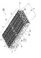
これらの図に示す電源装置は、複数の角形電池からなる電池セル1を冷却隙間4ができる状態で積層している電池ブロック3と、この電池ブロック3の電池セル1に冷却気体を強制送風して冷却する強制送風機構9とを備える。電池ブロック3は、積層している電池セル1の間にセパレータ2を挟着している。このセパレータ2は、図7に示すように、電池セル1との間に冷却隙間4ができる形状としている。さらに、図のセパレータ2は、両面に電池セル1を嵌着構造で連結している。電池セル1に嵌着構造で連結されるセパレータ2を介して、隣接する電池セル1の位置ずれを阻止して積層している。 The power supply device shown in these drawings includes a
角形電池の電池セル1は、リチウムイオン二次電池である。ただし、電池セルは、ニッケル水素電池やニッケルカドミウム電池等の二次電池とすることもできる。図7の電池セル1は、所定の厚さを有する四角形で、上面の両端部には正負の電極端子13を突出して設けており、上面の中央部には安全弁の開口部1Aを設けている。積層される電池セル1は、隣接する電極端子13を連結具(図示せず)で連結して、互いに直列に接続される。電源装置は、隣接する電池セル1の正負の電極端子13を積層状態で連結して、互いに直列に接続している。電池セル1は、正負の電極端子13をバスバー(図示せず)で連結して互いに直列に接続することができる。隣接する電池セル1を互いに直列に接続する電源装置は、出力電圧を高くして出力を大きくできる。ただし、電源装置は、隣接する電池セルを並列に接続することもできる。電池セル1は、金属製の外装缶で製作している。この電池セル1は、隣接する電池セル1の外装缶のショートを防止するために絶縁材のセパレータ2を挟着している。電池セルは、外装缶をプラスチックなどの絶縁材で製作することもできる。この電池セルは、外装缶を絶縁して積層する必要がないので、セパレータを金属製とすることもできる。 The
セパレータ2は、プラスチック等の絶縁材で製作して、隣接する電池セル1を絶縁している。セパレータ2は、図7の斜視図に示すように、電池セル1間に挿入されてこれらを絶縁すると共に、電池セル1同士の間に冷却隙間4を形成するためのスペーサとして機能する。この結果セパレータ2を介在させて電池セル1を積層した電池ブロック3は、図4の側面図に示すように、電池セル1との間に、電池セル1を冷却するための冷却気体を通過させる冷却隙間4を設けている。冷却気体には、空気や冷媒で熱交換した空気、或いは冷媒等が利用できる。図7のセパレータ2は、電池セル1との対向面に、両側縁まで延びる溝2Aを設けて、電池セル1との間に冷却隙間4を設けている。図のセパレータ2は、複数の溝2Aを、互いに平行に所定の間隔で設けている。図7のセパレータ2は、両面に溝2Aを設けており、互いに隣接する電池セル1とセパレータ2との間に冷却隙間4を構成する。この構造は、セパレータ2の両側に形成される冷却隙間4で、両側の電池セル1を効果的に冷却できる特長がある。ただ、セパレータは、片面にのみ溝を設けて、電池セルとセパレータとの間に冷却隙間を設けることもできる。図の冷却隙間4は、電池ブロック3の左右に開口するように水平方向に設けられている。さらに、図7のセパレータ2は、両側に切欠部2Bを設けている。このセパレータ2は、両側に設けた切欠部2Bにおいて、隣接する電池セル1の対向面の間隔を広くして、冷却気体の通過抵抗を少なくできる。このため、冷却気体を切欠部2Bからセパレータ2と電池セル1との間の冷却隙間4にスムーズに送風して、電池セル1を効果的に冷却できる。以上のように、冷却隙間4に強制送風される空気は、電池セル1の外装缶を直接に効率よく冷却する。この構造は、電池セル1の熱暴走を有効に阻止しながら、電池セル1を効率よく冷却できる特徴がある。
(エンドプレート10)The
(End plate 10)
電池ブロック3は、図4等に示すように、両端にエンドプレート10を設けて、一対のエンドプレート10を連結材11で連結して、積層している電池セル1とセパレータ2とを挟着する状態に固定している。エンドプレート10は、電池セル1の外形にほぼ等しい外形の四角形としている。連結材11は、図6に示すように、両端を内側に折曲して折曲片11dをエンドプレート10に止ネジ12で固定している。図示しないが、連結材の折曲部分を延長して、エンドプレートの全幅を囲むようにして止ネジで固定することもできる。あるいは、エンドプレートの側面に雌ねじ孔を設けて、連結材を貫通する止ネジをねじ込んで固定してもよい。このようにエンドプレートの外側面に固定される連結材は折曲片を設けることなく、直線状としてエンドプレートに固定される。 As shown in FIG. 4 and the like, the
図6のエンドプレート10は、外側に補強リブ10Aを一体的に成形して設けて補強している金属製である。金属製のエンドプレート10は十分な強度を有し、止ネジ12の締結トルクにも耐性を有する。さらに、エンドプレート10の外側の表面に、連結材11の折曲片11dを連結する連結孔10aを設けている。図6のエンドプレート10は、外側表面の四隅部に4個の連結孔10aを設けている。連結孔10aは雌ネジ穴である。このエンドプレート10は、連結材11を貫通する止ネジ12を雌ネジ穴にねじ込んで連結材11を固定することができる。ただエンドプレートは金属製に限られず、成型しやすさや絶縁性等で有利な樹脂製としてもよい。
(連結材11)The
(Connecting material 11)
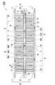
連結材11は、所定の上下幅を有するバインドバー11Xである。バインドバー11Xの連結材11は、所定の幅を有する金属板である。エンドプレート10の四隅部に両端を固定している連結材11であるバインドバー11Xは、電池セル1の両側であって、その上下に配設される。両側の上下にバインドバー11Xを配置している電池ブロック3は、図4に示すように、電池セル1の間に設けている冷却隙間4の上下の一部をバインドバー11Xで閉塞することになる。すなわち、バインドバー11Xで閉塞される冷却隙間4は、開口部14から冷却気体が流入されない。したがって、電池セル1の両側に開口している冷却隙間4の開口部14は、このバインドバー11Xで閉塞される上下に位置する閉塞部14Aと、バインドバー11Xで開口部14が閉塞されない露出部14Bとに区画される。露出部14Bは、上下の閉塞部14Aの間にあって送風ダクト5に連通される。この露出部14Bは、供給ダクト6に連通されて、供給ダクト6から冷却気体が強制送風される。電池ブロック3は、その両側面の上下にバインドバー11Xを配置しているので、両側に開口する冷却隙間4は、バインドバー11Xによって上下の閉塞部14Aと、露出部14Bとに区画される。一方の露出部14Bは供給ダクト6に連通され、他方の露出部14Bは排出ダクト7に連通されて、冷却気体に送風される冷却気体で電池セル1は冷却される。 The connecting
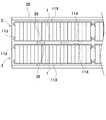
以上の電池ブロック3は、図2、図3及び図5に示すように、2列に分離して配列されて、2列の電池ブロック3同士の間と、その外側に送風ダクト5が設けられる。具体的には、2列の電池ブロック3同士の間に、各々の冷却隙間4に連通する供給ダクト6を設けている。さらに、2列に分離された電池ブロック3の外側には排出ダクト7を設けており、排出ダクト7と供給ダクト6との間に複数の冷却隙間4を並列に連通している。この電源装置は、図1と図3の矢印で示すように、強制送風機構9でもって供給ダクト6から排出ダクト7に向けて冷却気体を強制送風して電池セル1を冷却する。供給ダクト6から排出ダクト7に強制送風される冷却気体は、供給ダクト6から分岐されて、各々の冷却隙間4に送風されて電池セル1を冷却する。電池セル1を冷却した冷却気体は、排出ダクト7に集められて排気される。
(実施例2)The battery blocks 3 described above are arranged in two rows as shown in FIGS. 2, 3 and 5, and the
(Example 2)
なお以上の電源装置は、複数平行に並べた電池ブロック同士の間に供給ダクトを設けて、外側に排出ダクトを設け、内側から外側に向かって冷却気体を送出する形態としているが、冷却気体を電池ブロックに送出する形態はこの構成に限られない。例えば、供給ダクトと排出ダクトとを逆に配置して、外側から内側に向かって冷却気体を送出して冷却することもできる。このような例を実施例2として、図8に示す。図8に示す実施例2に係る電源装置200は、2列の電池ブロック3の外側に供給ダクト56を設けて、2列の電池ブロック3の間に、各々の冷却隙間4に連通する排出ダクト57を設けている。この電源装置200は、図8の矢印で示すように、強制送風機構9でもって、外側の供給ダクト56から中間の排出ダクト57に向けて冷却気体を強制送風して電池セル1を冷却する。外側の供給ダクト56から強制送風される冷却気体は、各々の冷却隙間4に送風されて電池セル1を冷却する。電池セル1を冷却した冷却気体は、中間の排出ダクト57に集めて排気される。 The above power supply device has a configuration in which a supply duct is provided between a plurality of battery blocks arranged in parallel, a discharge duct is provided on the outside, and cooling gas is sent from the inside to the outside. The form sent out to the battery block is not limited to this configuration. For example, the supply duct and the discharge duct may be arranged in reverse, and the cooling gas may be sent from the outside toward the inside for cooling. Such an example is shown in FIG. The
以上の図1〜図3及び図8の電源装置は、4組の電池ブロック3からなり、これら4個の電池ブロック3を、2行2列に配列している。各行を構成する2個の電池ブロック3は、2列に平行に並べて、中間と外側に送風ダクト5、55を設けている。さらに、図に示す電源装置は、互いに平行に並べた2個ずつの電池ブロック3を2行に分離して配置している。すなわち、図5に示すように、互いに隣接する行を構成する2個ずつの電池ブロック3の間に中間遮断壁19を配置して、各行の電池ブロック3の中間と外側に設けられる送風ダクト5、55同士を遮断している。したがって、この電源装置は、図3と図8に示すように、各行の電池ブロック3に、別々の供給ダクト6、56から冷却気体を供給し、冷却隙間4に強制送風した冷却気体を別々の排出ダクト7、57から排出している。図の電源装置は、供給ダクト6、56と排出ダクト7、57に、冷却気体を逆方向に強制送風して、電池セル1を冷却している。 The power supply apparatus shown in FIGS. 1 to 3 and FIG. 8 includes four
以上の電源装置は、2列に並列に配置してなる2個の電池ブロック3を、2行に分離して、全体で2行2列に配置している。ただ電源装置は、2列に並列に配置してなる2個の電池ブロックのみで構成すること、すなわち1行2列に配置することもできる。この電源装置は、供給ダクトと排出ダクトに、冷却気体を逆方向に強制送風して電池セルを冷却することも、同じ方向に強制送風して電池セルを冷却することもできる。さらに、2行2列に配置される4個の電池ブロックは、各行の電池ブロックの間と送風ダクトの間に中間遮断壁を配置することなく、列方向に隣接する2個の電池ブロックを直線状に連結すると共に、これらの電池ブロックを2列平行に並べて、中間と外側に送風ダクトを設けることもできる。この電源装置は、2行2列に配置される電池ブロックの中間に設ける送風ダクトと外側に設ける送風ダクトのいずれか一方を供給ダクトとして他方を排出ダクトとし、供給ダクトから供給される冷却気体を冷却隙間に強制送風して排出ダクトから排出する。この電源装置も、供給ダクトと排出ダクトに、冷却気体を逆方向に強制送風して電池セルを冷却することも、同じ方向に強制送風して電池セルを冷却することもできる。 In the above power supply apparatus, two
互いに平行に配列される2列の電池ブロック3の間に設けられる送風ダクト5の面積は、2列の電池ブロック3の外側に設けられる送風ダクト5の面積の2倍とする。それは、図1〜図3に示す電源装置においては、2個の電池ブロック3の中間に設けた供給ダクト6に強制送風される冷却気体を2分岐して、両側に設けた排出ダクト7に送風して排気し、図8に示す電源装置においては、両側に設けた2つの供給ダクト56に強制送風される冷却気体を、中間に設けた排出ダクト57に送風して排気するからである。すなわち、図1〜図3に示す電源装置において、供給ダクト6は、両側の排出ダクト7の2倍の冷却気体を送風するので、その断面積を2倍として圧力損失を小さくする。図3の電源装置は、中間の送風ダクト5である供給ダクト6の断面積を大きくするために、供給ダクト6の横幅を排出ダクト7の横幅の2倍としている。また、図8に示す電源装置において、中間の排出供給ダクト57は、両側の供給ダクト56の2倍の冷却気体を送風するので、その断面積を2倍として圧力損失を小さくする。さらに中間の送風ダクト55である排出ダクト57の断面積を大きくするために、排出ダクト57の横幅を供給ダクト56の横幅の2倍としている。
(実施例3)The area of the
(Example 3)
以上の電源装置は、電池ブロック3を互いに平行に2列に配列しており、2列に配列される電池ブロック3の中間と外側に送風ダクト5、55を設けている。ただ、電源装置は、1列の電池ブロックで構成することもできる。図9に示す実施例3に係る電源装置300は、1列の電池ブロック3の両側に送風ダクト75を設けており、一方の送風ダクト75を供給ダクト76として、他方の送風ダクト75を排出ダクト77としている。この電源装置300は、図9の矢印で示すように、強制送風機構9でもって、供給ダクト76から排出ダクト77に向けて冷却気体を強制送風して電池セル1を冷却する。供給ダクト76から強制送風される冷却気体は、各々の冷却隙間4に送風されて電池セル1を冷却する。電池セル1を冷却した冷却気体は、排出ダクト77に集合して排気される。この電源装置300は、供給ダクト76と排出ダクト77に送風される冷却気体の流量が等しくなるので、電池ブロック3の両側に設けられる供給ダクト76と排出ダクト77の断面積を等しく、すなわち、供給ダクト76の横幅と排出ダクト77の横幅とを等しくしている。
(温度均等化プレート15)In the above power supply device, the battery blocks 3 are arranged in two rows in parallel to each other, and the
(Temperature equalization plate 15)
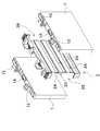
この電源装置100、200、300は、電池ブロック3の側面に、温度均等化プレート15を固定することができる。温度均等化プレート15は、風上側の電池セル1の冷却がより制限されるように、冷却隙間4を部分的に閉塞するように配置される。これにより冷却気体の流入を阻害し、流量が規制される。このとき、冷却隙間4の閉塞量が、冷却気体の進行方向に沿って小さくなるように構成することで、各々の電池セル1の温度差を少なくすることができる。図4〜図6に示す電池ブロック3は、その高さ方向の幅が電池ブロック3の端縁、すなわち風上側に向かうほど幅広に形成した温度均等化プレート15を固定している。 In the
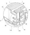
以下、図10〜図24に基づいて温度均等化プレート15及びその固定構造を説明する。これらの図において、図10は温度均等化プレート15を電池ブロック3に固定する状態を示す斜視図、図11は図10の分解斜視図、図12は図11の温度均等化プレート15の斜視図、図13は図12の温度均等化プレート15を背面から見た斜視図、図14は図12の温度均等化プレート15のXIV−XIV線における横断面図、図15は図12の温度均等化プレート15のXV−XV線における縦断面図、図16は図10のXVI−XVI線における水平断面斜視図、図17は図10のXVII−XVII線における水平垂直断面図、図18は変形例に係る温度均等化プレート15Bを背面から見た斜視図、図19は図18の温度均等化プレート15Bに弾性体41を固定した状態を示す斜視図、図20はバインドバー11Xの斜視図、図21は図20のバインドバー11Xの突起挿入部39を示す拡大斜視図、図22は変形例に係るバインドバー11Yの斜視図、図23は図22のバインドバー11Yの突起挿入部39を示す拡大斜視図、図24は電池ブロック3を平行に配置した状態でバインドバー11Xの突起挿入部39同士を当接させる状態を示す平面図を、それぞれ示している。 Hereinafter, the
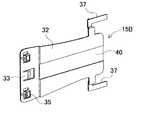
温度均等化プレート15は冷却気体の風路上に配置され、その流れを阻害する邪魔板として機能する。温度均等化プレート15は、図12、図13の斜視図に示すように、プレート本体32を等脚台形状に形成される。またプレート本体32の幅広側の中央には係止爪33が、幅狭側の両側には固定突起37が、それぞれ設けられる。この温度均等化プレート15を図10、図11に示すように電池ブロック3の側面に装着することで、各電池セル1の冷却隙間4の開口面積を、電池セル1積層方向に従って連続的に変化させることができる。 The
また温度均等化プレート15は風上側に固定される。これにより、風上側に位置する電池セルが冷却気体で冷却され過ぎて温度が低下する結果、他の電池セルとの温度差が大きくなる事態を、温度均等化プレート15で冷却隙間4を部分的に塞ぐことにより風量を制限して抑制する。なお温度均等化プレート15は電池ブロックの側面ですべての電池セルを被覆する必要はなく、各電池セルの温度差を低減できれば足りる。このため、図10等に示すように、風上側の幾つかの電池セル1を被覆できる大きさに構成されている。
(係止爪33)The
(Locking claw 33)
図10の例では、温度均等化プレート15はエンドプレート10に固定されている。温度均等化プレート15をエンドプレート10に固定するため、プレート本体32の風上側に面した幅広の端面には係止爪33が設けられている。係止爪33は図13の斜視図、図14の断面図に示すように、幅方向のほぼ中央で、電池ブロック3側に爪を突出させた鉤爪状に形成される。またこれに対応してエンドプレート10には、図11に示すように、係止爪33を係止する係止孔34を形成している。 In the example of FIG. 10, the
さらに温度均等化プレート15の係止爪33の上下には、エンドプレート10に当接、挿入するボス35を突出させている。またこれに応じてエンドプレート10側には、ボス35を挿入するボス穴36を形成している。この係止爪33を係止孔34に係止し、さらにボス35をボス穴36に挿入して、温度均等化プレート15はエンドプレート10に固定される。 Further, on the upper and lower sides of the locking
このような温度均等化プレート15は、耐熱性のある樹脂や金属板で構成される。この例では、絶縁性に優れたプラスチック製としている。好ましくは、係止爪33やボス35、固定突起37を一体に成型することで、安価に温度均等化プレート15を構成できる。安価に製造可能な温度均等化プレート15は、様々な電源装置に柔軟に利用できる利点が得られる。すなわち、図28のようにバインドバー2811に温度均等化プレート2815を固定したり、図29のようにバインドバー2911自体を温度均等化プレートに兼用する構成では、要求される電圧に応じて電池ブロックを構成する電池セル数が変化するなどして、電池ブロックの形状が変更されると、新たに設計し直す必要があり、コストが高くなる。これに対して、温度均等化プレートを別部材とすることでバインドバーの設計を簡素化し、電池ブロックの形状の変更を簡単かつ低コストで行える上、温度均等化プレートの固定構造及び固定作業も容易化でき、製造コストの低減に有利となる。 Such a
図3、図8の平面図に示す例では、電池ブロック3の側面の内で片側のみ、冷却気体の流入側に固定されている。このように流入側のみに温度均等化プレート15を固定することで、両側に温度均等化プレートを設けなくとも十分に冷却気体を抑制でき、温度均等化プレートの枚数を少なくして構造の簡素化とコスト削減を図ることができる。
(固定突起37)In the examples shown in the plan views of FIGS. 3 and 8, only one side of the side surface of the
(Fixing protrusion 37)
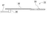
また温度均等化プレート15の風下側は、バインドバー11Xに固定されている。このため温度均等化プレート15のプレート本体32には、係止爪33を設けた側と反対側、すなわち冷却気体の風下側に固定突起37が設けられる。具体的には温度均等化プレート15は、プレート本体32の側面から横方向に突出する突出部38と、この突出部38からプレート本体32の延長方向に折曲された姿勢で突出する固定突起37を備えている。このようにして固定突起37は、バインドバー11Xの延長方向に沿う姿勢に設けられている。 Further, the leeward side of the
このように固定突起37を突起挿入部39に挿入し、さらに係止爪33を係止孔34に係止して、温度均等化プレート15を電池ブロック3に固定する構成によって、ねじ止めなどの作業を無くし、組み立て工程における固定の作業を簡素化できる利点が得られる。 In this way, the fixing
さらに固定突起37を設けた突出部38は、図12及び図13の斜視図並びに図17の断面図に示すように、プレート本体32の平面から離間するよう段差状に折曲されている。プレート本体32と固定突起37の離間距離すなわち突出部38の段差の高低差は、バインドバー11Xと電池ブロック3の側面の高低差に応じて設計される。これにより、固定突起37をバインドバー11Xの突起挿入部39(詳細は後述)に挿入した状態で、プレート本体32が電池ブロック3の側面に接するように配置できる。またプレート本体32は、図17及び図15の断面図に示すように、側面視を凹状に湾曲させている。これにより、プレート本体32を電池ブロック3の側面と確実に密着させることができ、冷却隙間4を確実に閉塞できる。
(弾性体41)Further, the protruding
(Elastic body 41)
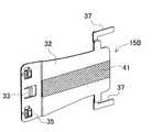
さらに好ましくは、温度均等化プレート15と電池ブロック3との間に弾性体41を介在させる。図18の斜視図に示す例では、温度均等化プレート15Bのプレート本体32の長さ方向に沿って中央には凹部40が形成されており、ここに図19に示すように弾性体41を固定する。弾性体41はゴム製シートが好適に利用できる。このように弾性体41を介在させることで、温度均等化プレート15Bと電池ブロック3とを一層密着させ、冷却隙間4の閉塞を確実ならしめると共に、温度均等化プレート15Bが冷却気体にあおられてばたついたり振動する事態を回避し、振動音の発生も抑制できる利点が得られる。弾性体41は、プレート本体32の凹部40に接着して固定する他、温度均等化プレートにインサート成型で固定することもできる。あるいは、温度均等化プレート自体を弾性体で構成してもよい。 More preferably, an
また弾性体41の面積は、電池ブロック3を構成する電池セル1の積層方向に沿って、徐々に狭くするように構成してもよい。これにより、プレート本体32の面積を変化させると共に弾性体41の面積も変化させて、電池セル間の温度差ΔTを一層低減できる。
(突起挿入部39)Further, the area of the
(Projection insertion part 39)
一方で、バインドバー11Xは、図20及び図21の斜視図に示すように、固定突起37を挿入する突起挿入部39を設けている。突起挿入部39は、バインドバー11Xの延長方向と直交する方向に、固定突起37を挿入できる内径に開口している。また固定突起37は、バインドバー11Xの幅とほぼ同じか、これよりも狭い幅に形成することが好ましい。このように構成することで、固定突起37を突起挿入部39に挿入すると、固定突起37がバインドバー11Xと重なる状態となって、余分な広がりを抑制できる。この結果、温度均等化プレート15で冷却隙間4を閉塞する面積を極力変更することなく、温度均等化プレート15をバインドバー11Xに固定できる。いいかえると、温度均等化プレート15のプレート本体32の大きさは、冷却隙間の閉塞量を電池セル毎に変更するように設計されているので、電池ブロック3側面への余計な突出や変形は極力少なくすることが好ましいといえる。上記のように突起挿入部39をバインドバー11Xと重なるように配置して固定することで、電池ブロック3側面への突出量を、プレート本体32と固定突起37とを繋ぐ突出部38のみに抑えて必要最小限に止め、冷却隙間への影響を抑制できる。 On the other hand, as shown in the perspective views of FIGS. 20 and 21, the
さらに好ましくは、図10に示すように突出部38が、電池セル1と重なるように、いいかえると冷却隙間4を閉塞しない位置となるように、突出部38をプレート本体32に設ける位置が設定される。これによって、突出部38で冷却隙間を閉塞する事態を回避し、温度均等化プレート15の本体の機能である、冷却気体の流れに沿って電池セル毎に冷却隙間の閉塞量を徐々に小さくして冷却気体の風量を大きくすることが可能となる。 More preferably, the position where the
加えて、固定突起37をバインドバー11Xの長さ方向と一致させることで、固定突起37を長くできる利点も得られる。すなわち、図30に示すように固定突起37をバインドバー11Xと交差させる姿勢とすると、固定突起37の長さを短くする必要があり、突起挿入部39との当接面積が小さくなる結果、保持力も相対的に低くなる。これに対して、固定突起37をバインドバー11Xと重なる位置に配置することで、固定突起37の長さを十分に長くできるので、突起挿入部39も長くして接触抵抗を増し、長期に渡って安定的に温度均等化プレート15を保持して信頼性も向上できる。 In addition, by making the fixing
突起挿入部39の長さは、固定突起37の長さに応じて設計され、好ましくは固定突起37の半分以上を挿入できる深さとする。図20及び図21の例では、スリップ状の金属片を両端で断面視U字状に折曲して、断面視C字状の突起挿入部39を形成している。この突起挿入部39は、中心をスリット状に開口しており、変形しやすくして突起挿入部39の内径を調整できる。 The length of the
なお図21の例では、バインドバー11Xとは別個の金属片を溶接などにより固定して突起挿入部39を形成しているが、バインドバーと一体的に突起挿入部を形成してもよい。例えば、バインドバーとして中間部分で上下に突出させた金属板を使用し、この突出部分を折曲して突起挿入部を形成できる。 In the example of FIG. 21, the
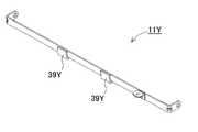
このバインドバー11Xはアルミニウム等の金属製とし、一定幅の金属板の両端を折曲して、エンドプレート10の固定部分を形成する。また突起挿入部39は、上記の例に限られず、固定突起37を挿入できる他の形態が適宜利用できる。例えば図22及び図23に示す変形例に係るバインドバー11Yでは、一体成型した折曲片を片側に一枚のみ突出させて、これを折曲して先端部分を溶接し、突起挿入部39Yを形成している。この突起挿入部39Yはバインドバーと別部材を使用しないで形成できるため、安価に製造できるメリットがある。 The
さらに好ましくは、バインドバーを対称な形状とする。図20等の例では、バインドバー11Xの長さ方向の中心に対して対称な位置に突起挿入部39を2つ設けている。このバインドバー11Xは、一方の突起挿入部39(図20において左側)を使用して、他方の突起挿入部39(図20において右側の第二突起挿入部39B)は使用しない。このようにしてバインドバー11Xを上下左右対称とすることで、逆向きにしても使用でき、電源装置の組み立て時において組間違いを無くし、作業効率を向上できる。 More preferably, the bind bar has a symmetrical shape. In the example of FIG. 20 and the like, two
加えて、複数の電池ブロック3を平行に並べて配置する際には、2つの突起挿入部39で隣接する電池ブロック3同士を当接させることができ、当接の応力を2つの突起挿入部39で分散できるので、より強固な狭持も図られ、信頼性の面でも好ましい。具体的には、図24の平面図に示すように、電池ブロック3を外装ケース20内に平行に配置した状態でブラケットなどにより固定する際、バインドバー11Xの突起挿入部39同士が当接するため、金属部材同士の接触によって強固に固定できる。また、突起挿入部39同士が押し当てられて若干変形すると、その内径が狭くなるため、ここに挿入された固定突起37がより確実に固定されて温度均等化プレート15の抜け落ちが阻止されるという副次的な利点も得られる。 In addition, when the plurality of
以上の例では、温度均等化プレート15は嵌合構造で電池ブロック3に固定している。嵌合構造はねじ止めや溶接などの作業が不要で、スナップ式に装着でき、作業性に優れる。ただ、本発明は嵌合構造に限定するものでなく、要求される強度や信頼性に応じて、ネジ止めや接着、溶接などの方法で温度均等化プレートをバインドバー11Xの表面に固定することもできる。また嵌合構造も上記構成に限られず、既存の嵌合の機構を適宜利用できる。
(温度均等化壁8、58)In the above example, the
(
さらに供給ダクト6、56、76には温度均等化壁8、58を配置して、電池セル1の温度差を少なくしている。温度均等化壁8、58は、冷却気体の送風方向の全長を横幅よりも大きくしている細長い形状であって、風上側の端部を先端に向かって次第に細くしている。図4〜図5の温度均等化壁8、58は、風下側の端部も先端に向かって次第に細くして、風下側における冷却気体の乱流を少なくしてスムーズに送風できるようにしている。供給ダクト6、56、76内における乱流は、圧力損失を増加させる原因となる。したがって、温度均等化壁8、58の風上側と風下側の両方を先端に向かって次第に細くする構造は、乱流による圧力損失を少なくできる。 Further,
さらに、図の温度均等化壁8、58は、風上側と風下側の端部を、先端に向かって上下幅を狭くするように傾斜する形状として、全体の形状を中央部を高くする山形としている。図5の電源装置は、供給ダクト6、56、76の上下の対向位置に温度均等化壁8、58を配設しているので、供給ダクト6、56、76の下側に配設される温度均等化壁8、58は、先端に向かって下り勾配に傾斜する形状とし、上側に配設される温度均等化壁8、58は、先端に向かって登り勾配に傾斜する形状として、全体を山形にしている。供給ダクト6、56、76の上下に温度均等化壁8、58を配置する構造は、温度均等化壁8、58を低くして、すなわち上下幅の狭い温度均等化壁を設けて電池セルの温度差を少なくできるので、圧力損失をより少なくしながら、電池セルの温度差も少なくできる。ただし、本発明の電源装置は、必ずしも供給ダクトの上下に温度均等化壁を配置する必要はなく、たとえば、図示しないが、供給ダクトの上側のみに、あるいは下側のみに温度均等化壁を配置することもできる。 Furthermore, the
さらに、温度均等化壁8、58は、頂上縁に向かって次第に横幅を狭くするテーパ部8A、58Aを設けて、電池ブロック3の対向面との間隔を頂上縁に向かって次第に広くしている。下側の温度均等化壁8、58のテーパ部8A、58Aは、上方に向かって横幅を次第に狭くして、電池ブロック3の対向面との間隔を次第に広くしている。上側の温度均等化壁8、58のテーパ部8A、58Aは、下側に向かって横幅を次第に狭くして、電池ブロック3の対向面との間隔を次第に広くしている。図5の温度均等化壁8、58は、全体をテーパ部8A、58Aとすることなく、上下方向に分けてテーパ部8A、58Aと幅広部8B、58Bとを設けている。下側の温度均等化壁8、58は幅広部8B、58Bを下に、テーパ部8A、58Aを上に設けており、上側の温度均等化壁8、58は幅広部8B、58Bを上に、テーパ部8A、58Aを下に設けている。幅広部8B、58Bは、横幅を変化させない形状とし、あるいは上下方向に横幅を変化させる割合をテーパ部8A、58Aよりも少なくして両側面を垂直面ないし垂直面に近い状態としている。 Further, the
図4〜図5の電源装置は、2列の電池ブロック3の間に供給ダクト6を設けて、ここに温度均等化壁8を配置しているので、温度均等化壁8のテーパ部8Aは、両面の傾斜角(α)を同じ角度として、両面に配設している電池ブロック3の対向面との間隔を同じにしている。両側の電池ブロック3の電池セル1を均一に冷却するためである。また、電源装置は、2列の電池ブロック3の外側に供給ダクト56を設けて、ここに温度均等化壁58を配置しているので、温度均等化壁58のテーパ部58Aは、電池ブロック3との対向面である内側面を傾斜面として、外側面を垂直面としている。2列の電池ブロック3の両外側に設けられる供給ダクト56に対向して配置される温度均等化壁58は、傾斜角(α)を同じ角度として、電池ブロック3の対向面との間隔を左右対称にしている。2列の電池ブロック3の電池セル1を均一に冷却するためである。 4 to 5 is provided with the
テーパ部8A、58Aの水平面に対する傾斜角(α)は、幅広部8B、58Bの横幅とテーパ部8A、58Aの高さから特定される。テーパ部は、傾斜角(α)を大きく、かつ幅広部の横幅を広くしてテーパ部を高く、傾斜角(α)を小さく、幅広部の横幅を狭くしてテーパ部を低くする。 The inclination angle (α) of the tapered
以上の温度均等化壁8、58は、テーパ部8A、58Aの送風方向の長さと高さとを、電池セル1の温度差が最低となる値に設定する。図3、図8に示す電源装置は、送風方向において風下側に配置している電池セルの温度が風上側の電池セルよりも高くなる。図3、図8の電源装置は、風下側の電池セルの温度を低くして、電池セルの温度差を少なくするために、供給ダクト6、56、76の風下側に温度均等化壁8、58を配置している。この温度均等化壁8、58は、風下側の半分に配置している電池セルの温度差をさらに少なくするように、送風方向の長さと、テーパ部8A、58Aの高さを特定している。 The above
温度均等化壁を設けない電源装置は、電池ブロックの風上側に配置している全体の1/2の電池セル、すなわち9個の電池セルと、風下側に配置している1/2の電池セルである9個の電池セルに温度差ができる。とくに、風下側に配置している9個の電池セルは温度が高くなって、温度差も大きくなる。供給ダクト6、56、76の流入側と排出側に配置される電池セル1は、両側のエンドプレート10から冷却されて温度が低くなる。また、流入側から冷却された気体が流入されることから、風下側に配置している電池セルの温度が最も高くなる。風下側に配置している9個の電池セルは、その中央に配置している14個目の電池セルの温度が最も高くなる。風下側の中央に配置している電池セルよりも風上側や風下側になるしたがって、電池セルの温度は低くなる。たとえば、風下側の中央に配置している電池セルの温度が約34℃に上昇するとき、風下側の両端部に配置している電池セル、すなわち10番目と18番目の電池セルの温度は30℃以下となる。この状態で、風上側の最も低温の電池セルの温度は約23℃となる。 The power supply device without the temperature equalizing wall is a half battery cell arranged on the windward side of the battery block, that is, nine battery cells, and a half battery arranged on the leeward side. There is a temperature difference between the nine battery cells. In particular, nine battery cells arranged on the leeward side have a high temperature and a large temperature difference. The
図の電源装置は、供給ダクト6、56、76の風下側に配置している電池セル1をより効率よく冷却するために、供給ダクト6、56、76の風下側に温度均等化壁8、58を配置している。この温度均等化壁8、58は、風下側に配置している各々の電池セル1の温度を低くすると共に、温度差を少なくするように、送風方向の長さと、テーパ部8A、58Aの高さを特定している。温度均等化壁8、58は、供給ダクト6、56、76内にあって、強制送風される冷却気体をより効率よく冷却隙間4に流入して、温度が高くなる電池セル1の温度を低下させる。 In the illustrated power supply apparatus, in order to more efficiently cool the
図4ないし図5の電源装置は、温度均等化壁8、58の幅広部8B、58Bを、電池ブロック3のバインドバー11Xと対向する位置に配置して、温度均等化壁8、58のテーパ部8A、58Aを電池ブロック3の露出部14Bと対向する位置に配置している。すなわち、幅広部8B、58Bは、電池ブロック3の閉塞部14Aの外側に配置され、テーパ部8A、58Aを露出部14Bの外側に配置している。電源装置は、温度均等化壁8の幅広部8Bを、2列に配置している電池ブロック3のバインドバー11Xの間に配置して、温度均等化壁8のテーパ部8Bを2列の電池ブロック3の露出部14Bの間に配置している。 4 to 5, the
ここで、閉塞部14Aは、バインドバー11Xで開口部14を閉塞しているので、仮に閉塞部14Aの外側に冷却気体を送風するとしても、冷却気体が冷却隙間4に流入することはない。図8の断面図に示す電源装置は、その風下側に配設している温度均等化壁8、58の幅広部8B、58Bを、連結材11のバインドバー11Xとの間に隙間ができないように、あるいは、バインドバーに接近して配置する。この構造の電源装置は、電池ブロック3の風下側において、バインドバー11Xで閉塞される閉塞部14Aの外側には冷却気体を送風せず、送風される全ての冷却気体を電池ブロック3の露出部14Bに送風し、露出部14Bからスムーズに効率よく冷却隙間4に流入して電池セル1を効率よく冷却する。 Here, since the closing
さらに、テーパ部8A、58Aは、露出部14Bに突出して、電池温度が高くなる領域で上下幅を広くして、露出部14Bとの対向面にテーパ部8A、58Aを配置している。したがって、供給ダクト6、56、76に送風される冷却気体は、テーパ部8A、58Aと露出部14Bとの間を流動し、テーパ部8A、58Aでもって流速が速くなり、また、テーパ部8A、58Aによってスムーズに冷却隙間4に流入されて、電池セル1を効率よく冷却する。したがって、温度均等化壁8、58は、電池セル1の温度が最も高くなる領域に、テーパ部8A、58Aの最も上下幅の広い領域を配置することで、温度が高くなる電池セルを他の電池セルよりも効率よく冷却して、電池温度を低くできる。したがって、温度均等化壁8、58は、テーパ部8A、58Aの上下幅で高温になる電池セルの冷却効率を特定し、テーパ部8A、58Aの送風方向の長さで温度を低下させる電池セルを特定できる。図3ないし図5、図8の電源装置は、風下側の電池セルをより効率よく冷却するために、供給ダクト6、56、76の風下側に温度均等化壁8、58を配置し、さらに風下側にあって温度が高くなる電池セルの領域でテーパ部8A、58Aを高くしている。以上のように、温度均等化壁8、58は、その長さで冷却する電池セルの個数をコントロールでき、または上下幅で高温になる電池セルの冷却効率を特定できるので、温度均等化壁8、58を設けない状態で、温度が高くなる電池セルの領域に設けられ、さらに最も高温になる電池セルの最高温度を低下させる温度でテーパ部8A、58Aの高さを特定して、電源装置の温度差を最も少なくできる。 Furthermore, the
なお、以上の例では温度均等化プレート15と温度均等化壁とを用いて電池セルの均熱化を図っているが、本発明において温度均等化壁は必須でない。すなわち、温度均等化壁を省略することも可能である。 In the above example, the
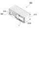
以上の電源装置は、電池ブロック3を外装ケース20に固定して定位置に配置している。図1と図2に示す電源装置は、外装ケース20を下ケース20Aと上ケース20Bとで構成する。上ケース20Bと下ケース20Aは、外側に突出する鍔部21を有し、この鍔部21をボルト24とナット25で固定している。図の外装ケース20は、鍔部21を電池ブロック3の側面に配置している。ただ、鍔部は、電池ブロックの上部や下部、あるいはその中間に配置することもできる。この外装ケース20は、エンドプレート10を下ケース20Aに止ネジ(図示せず)で固定して、電池ブロック3を固定している。止ネジは、下ケース20Aを貫通してエンドプレート10のネジ孔(図示せず)にねじ込まれて、電池ブロック3を外装ケース20に固定する。止ネジは、頭部を下ケース20Aから突出させている。さらに、図1と図2の外装ケース20は、内部に電池ブロック3を固定して、電池ブロック3の外側面と外装ケース20の側壁22の内面との間に送風ダクト5を設けている。 In the above power supply device, the
さらに、外装ケース20は、両端に端面プレート30を連結している。端面プレート30は、電池ブロック3に連結される状態で、供給ダクト6と排出ダクト7からなる送風ダクト5に連結される連結ダクト31を、プラスチックなどで一体的に成形して外側に突出するように設けている。この連結ダクト31は、強制送風機構9に連結され、あるいは電源装置から冷却気体を排気する外部排気ダクト(図示せず)に連結される。この端面プレートは、図示しないが、係止構造で電池ブロックのエンドプレートに連結している。ただ、端面プレートは、係止構造以外の連結構造で電池ブロックに連結し、あるいは、外装ケースに固定することもできる。 Further, the
以上の電源装置は、車載用のバッテリシステムとして利用できる。電源装置を搭載する車両としては、エンジンとモータの両方で走行するハイブリッドカーやプラグインハイブリッドカー、あるいはモータのみで走行する電気自動車などの電動車両が利用でき、これらの車両の電源として使用される。 The power supply device described above can be used as an in-vehicle battery system. As a vehicle equipped with a power supply device, an electric vehicle such as a hybrid car or a plug-in hybrid car that runs with both an engine and a motor, or an electric car that runs only with a motor can be used, and it is used as a power source for these vehicles. .
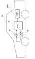
図25に、エンジンとモータの両方で走行するハイブリッドカーに電源装置を搭載する例を示す。この図に示す電源装置を搭載した車両HVは、車両HVを走行させるエンジン96及び走行用のモータ93と、モータ93に電力を供給するバッテリシステム100Bと、バッテリシステム100Bの電池を充電する発電機94とを備えている。バッテリシステム100Bは、DC/ACインバータ95を介してモータ93と発電機94に接続している。車両HVは、バッテリシステム100Bの電池を充放電しながらモータ93とエンジン96の両方で走行する。モータ93は、エンジン効率の悪い領域、例えば加速時や低速走行時に駆動されて車両を走行させる。モータ93は、バッテリシステム100Bから電力が供給されて駆動する。発電機94は、エンジン96で駆動され、あるいは車両にブレーキをかけるときの回生制動で駆動されて、バッテリシステム100Bの電池を充電する。 FIG. 25 shows an example in which a power supply device is mounted on a hybrid car that travels with both an engine and a motor. A vehicle HV equipped with the power supply device shown in this figure includes an
また図26に、モータのみで走行する電気自動車に電源装置を搭載する例を示す。この図に示す電源装置を搭載した車両EVは、車両EVを走行させる走行用のモータ93と、このモータ93に電力を供給するバッテリシステム100Cと、このバッテリシステム100Cの電池を充電する発電機94とを備えている。モータ93は、バッテリシステム100Cから電力が供給されて駆動する。発電機94は、車両EVを回生制動する時のエネルギーで駆動されて、バッテリシステム100Cの電池を充電する。 FIG. 26 shows an example in which a power supply device is mounted on an electric vehicle that runs only with a motor. A vehicle EV equipped with the power supply device shown in this figure includes a traveling
本発明に係る車両用電源装置及びこれを備える車両並びに車両用電源装置の容量均等化方法は、EV走行モードとHEV走行モードとを切り替え可能なプラグイン式ハイブリッド電気自動車やハイブリッド式電気自動車、電気自動車などの容量均等化方法として好適に利用できる。 A vehicle power supply device, a vehicle including the vehicle power supply device, and a vehicle power supply device capacity equalization method according to the present invention include a plug-in hybrid electric vehicle, a hybrid electric vehicle, and an electric vehicle that can switch between an EV travel mode and an HEV travel mode. It can be suitably used as a capacity equalization method for automobiles and the like.
100、200、300…電源装置
100B、100C…バッテリシステム
1…電池セル;1A…安全弁開口部
2…セパレータ;2A…溝;2B…切欠部
3、283、293、303…電池ブロック
4、284、294、304…冷却隙間
5…送風ダクト
6…供給ダクト
7…排出ダクト
8、58…温度均等化壁;8A、58A…テーパ部
8B、58B…幅広部
9…強制送風機構
10、310…エンドプレート;10A…補強リブ;10a…連結孔
11…連結材;11d…折曲片
11X、11Y、2811、2911…バインドバー
12…止ネジ
13…電極端子
14…開口部;14A…閉塞部;14B…露出部
15、15B、2815、3015…温度均等化プレート
19…中間遮断壁
20…外装ケース;20A…下ケース;20B…上ケース
21…鍔部
22…側壁
24…ボルト
25…ナット
30…端面プレート
31…連結ダクト
32…プレート本体
33…係止爪
34…係止孔
35…ボス
36…ボス穴
37…固定突起
38…突出部
39、39Y…突起挿入部
39B…第二突起挿入部
40…凹部
41…弾性体
55…送風ダクト
56…供給ダクト
57…排出ダクト
75…送風ダクト
76…供給ダクト
77…排出ダクト
93…モータ
94…発電機
95…DC/ACインバータ
96…エンジン
101…電池セル
103…冷却隙間
106…供給ダクト
107…排出ダクト
110…電池ブロック
EV、HV…車両DESCRIPTION OF
Claims (14)
Translated fromJapanese前記複数の電池セル(1)を積層状態に締結するため、電池セル(1)の積層方向に延長された連結材(11)と、
前記電池ブロック(3)の側面で、前記冷却隙間(4)の流入側で、該冷却隙間(4)の開口部を部分的に遮るように配置された温度均等化プレート(15)と、
を備え、
前記電池ブロック(3)の側面から、前記冷却隙間(4)に冷却気体を送風することで前記電池セル(1)を冷却するよう構成すると共に、
前記冷却隙間(4)に流入される冷却気体の量が、冷却気体の風上側に位置する電池セル程少なくなるように、前記温度均等化プレート(15)が前記電池ブロック(3)の側面を覆う形状を変化させてなる電源装置であって、
前記温度均等化プレート(15)は、冷却気体の風上側を前記電池ブロック(3)と固定すると共に、冷却気体の風下側に位置する側に突出させた固定突起(37)を備えており、
前記連結材(11)は、前記固定突起(37)と対応する位置に、該固定突起(37)を挿入する突起挿入部(39)を、前記電池ブロック(3)の側面に設けており、
前記温度均等化プレート(15)の固定突起(37)を、前記連結材(11)の突起挿入部(39)に挿入して、前記温度均等化プレート(15)を前記連結材(11)に装着してなることを特徴とする電源装置。A battery block (3) formed by laminating a plurality of battery cells (1) with a cooling gap (4) for flowing cooling gas between them,
In order to fasten the plurality of battery cells (1) in a stacked state, the connecting material (11) extended in the stacking direction of the battery cells (1),
On the side of the battery block (3), on the inflow side of the cooling gap (4), a temperature equalizing plate (15) arranged to partially block the opening of the cooling gap (4),
With
From the side of the battery block (3), configured to cool the battery cell (1) by blowing cooling gas to the cooling gap (4), and
The temperature equalizing plate (15) is disposed on the side surface of the battery block (3) so that the amount of cooling gas flowing into the cooling gap (4) decreases as the battery cell is located on the windward side of the cooling gas. A power supply device in which a covering shape is changed,
The temperature equalizing plate (15) fixes the leeward side of the cooling gas to the battery block (3), and includes a fixing projection (37) protruding to the side located on the leeward side of the cooling gas,
The connecting member (11) is provided with a protrusion insertion portion (39) for inserting the fixing protrusion (37) on a side surface of the battery block (3) at a position corresponding to the fixing protrusion (37).
The fixing protrusion (37) of the temperature equalizing plate (15) is inserted into the protrusion insertion part (39) of the connecting member (11), and the temperature equalizing plate (15) is attached to the connecting member (11). A power supply device that is mounted.
前記温度均等化プレート(15)が、前記電池ブロック(3)に面する側に凹面を形成してなり、
前記凹面に弾性体(41)を配置してなることを特徴とする電源装置。The power supply device according to claim 1,
The temperature equalizing plate (15) is formed with a concave surface on the side facing the battery block (3),
A power supply device comprising an elastic body (41) disposed on the concave surface.
前記弾性体(41)の面積が、前記電池ブロック(3)を構成する電池セル(1)の積層方向に沿って、徐々に狭くするように構成してなることを特徴とする電源装置。The power supply device according to claim 2,
The power supply device, wherein the elastic body (41) is configured such that an area of the elastic body (41) is gradually reduced along a stacking direction of the battery cells (1) constituting the battery block (3).
前記温度均等化プレート(15)が前記電池ブロック(3)側に近付く方向に湾曲されてなることを特徴とする電源装置。The power supply device according to any one of claims 1 to 3,
The power supply device, wherein the temperature equalizing plate (15) is curved in a direction approaching the battery block (3) side.
前記温度均等化プレート(15)の形状が、等脚台形状に形成されてなることを特徴とする電源装置。The power supply device according to any one of claims 1 to 4,
The power supply device, wherein the temperature equalizing plate (15) is formed in an isosceles trapezoidal shape.
前記温度均等化プレート(15)が、電池ブロック(3)の側面の内、冷却気体の流入側にのみ固定されてなることを特徴とする電源装置。The power supply device according to any one of claims 1 to 5,
The power supply device, wherein the temperature equalizing plate (15) is fixed only to a cooling gas inflow side in a side surface of the battery block (3).
前記連結材(11)が、前記電池セル(1)の積層方向に延長された一定幅の金属製のバインドバー(11X)であって、
前記固定突起(37)が、前記バインドバー(11X)の延長方向に沿って突出され、かつ前記バインドバー(11X)の幅と等しいかこれよりも狭い幅に形成されてなることを特徴とする電源装置。The power supply device according to any one of claims 1 to 6,
The connecting material (11) is a metal bind bar (11X) having a constant width extended in the stacking direction of the battery cell (1),
The fixing protrusion (37) protrudes along the extending direction of the bind bar (11X) and is formed to have a width equal to or smaller than the width of the bind bar (11X). Power supply.
前記突起挿入部(39)が、前記バインドバー(11X)の幅方向に突出された一対の金属片を、それぞれ断面視U字状に折曲して形成されてなることを特徴とする電源装置。The power supply device according to claim 7,
The power supply device, wherein the protrusion insertion portion (39) is formed by bending a pair of metal pieces projecting in the width direction of the bind bar (11X) into a U-shape in sectional view. .
前記温度均等化プレート(15)はさらに、温度均等化プレート(15)と前記固定突起(37)とを接続する突出部(38)を備えており、
前記突出部(38)は、前記温度均等化プレート(15)を前記電池ブロック(3)の側面に固定した状態で、前記電池ブロック(3)を構成するいずれかの電池セル(1)と重なる位置に配置されてなることを特徴とする電源装置。The power supply device according to any one of claims 1 to 8,
The temperature equalizing plate (15) further includes a protrusion (38) connecting the temperature equalizing plate (15) and the fixing protrusion (37),
The protruding portion (38) overlaps any battery cell (1) constituting the battery block (3) in a state where the temperature equalizing plate (15) is fixed to the side surface of the battery block (3). A power supply device characterized by being arranged at a position.
前記連結材(11)は、その延長方向において、前記突起挿入部(39)を設けた位置と対称な位置に、前記突起挿入部(39)と同じ形状の第二突起挿入部(39B)を設けてなることを特徴とする電源装置。The power supply device according to any one of claims 1 to 9,
The connecting member (11) has a second protrusion insertion portion (39B) having the same shape as the protrusion insertion portion (39) at a position symmetrical to the position where the protrusion insertion portion (39) is provided in the extending direction. A power supply device characterized by being provided.
前記電池ブロック(3)の両端面から、前記電池セル(1)の積層体を狭持するエンドプレート(10)を備えており、
前記温度均等化プレート(15)が、前記固定突起(37)を設けた側と反対側に係止爪(33)を設けており、
前記エンドプレート(10)に、前記係止爪(33)を係止する係止孔(34)を設けており、
前記係止爪(33)を前記係止孔(34)に係止して、前記温度均等化プレート(15)の、冷却気体の風上側を前記電池ブロック(3)に固定してなることを特徴とする電源装置。The power supply device according to any one of claims 1 to 10, further comprising:
From both end faces of the battery block (3), it is provided with an end plate (10) for sandwiching the stacked body of the battery cells (1),
The temperature equalizing plate (15) is provided with a locking claw (33) on the side opposite to the side on which the fixing protrusion (37) is provided,
The end plate (10) is provided with a locking hole (34) for locking the locking claw (33),
The locking claw (33) is locked to the locking hole (34), and the airflow side of the cooling gas of the temperature equalizing plate (15) is fixed to the battery block (3). A featured power supply.
前記電池ブロック(3)に前記冷却隙間(4)を設けるために、電池セル(1)間に挿入される絶縁性のセパレータ(2)を設けてなることを特徴とする電源装置。The power supply device according to any one of claims 1 to 11, further comprising:
In order to provide the cooling gap (4) in the battery block (3), an insulating separator (2) inserted between the battery cells (1) is provided.
前記電池セル(1)が角形電池であることを特徴とする電源装置。The power supply device according to any one of claims 1 to 12,
The power supply device, wherein the battery cell (1) is a square battery.
Priority Applications (4)
| Application Number | Priority Date | Filing Date | Title |
|---|---|---|---|
| JP2010017492AJP5450128B2 (en) | 2010-01-28 | 2010-01-28 | Power supply device and vehicle equipped with the same |
| EP20110000625EP2362462A1 (en) | 2010-01-28 | 2011-01-26 | Power supply device with battery cell cooling mechanism and vehicle including the same |
| US13/015,947US8329330B2 (en) | 2010-01-28 | 2011-01-28 | Power supply device with battery cell cooling mechanism and vehicle including the same |
| CN2011100350478ACN102142588A (en) | 2010-01-28 | 2011-01-28 | Power supply device and vehicle including the same |
Applications Claiming Priority (1)
| Application Number | Priority Date | Filing Date | Title |
|---|---|---|---|
| JP2010017492AJP5450128B2 (en) | 2010-01-28 | 2010-01-28 | Power supply device and vehicle equipped with the same |
Publications (2)
| Publication Number | Publication Date |
|---|---|
| JP2011154985A JP2011154985A (en) | 2011-08-11 |
| JP5450128B2true JP5450128B2 (en) | 2014-03-26 |
Family
ID=43902822
Family Applications (1)
| Application Number | Title | Priority Date | Filing Date |
|---|---|---|---|
| JP2010017492AActiveJP5450128B2 (en) | 2010-01-28 | 2010-01-28 | Power supply device and vehicle equipped with the same |
Country Status (4)
| Country | Link |
|---|---|
| US (1) | US8329330B2 (en) |
| EP (1) | EP2362462A1 (en) |
| JP (1) | JP5450128B2 (en) |
| CN (1) | CN102142588A (en) |
Cited By (1)
| Publication number | Priority date | Publication date | Assignee | Title |
|---|---|---|---|---|
| US10615468B2 (en) | 2015-05-27 | 2020-04-07 | Mitsubishi Electric Corporation | Power storage device |
Families Citing this family (33)
| Publication number | Priority date | Publication date | Assignee | Title |
|---|---|---|---|---|
| US20120223113A1 (en)* | 2009-11-18 | 2012-09-06 | Benteler Aluminium Systems France SNC | Battery Tray for Vehicle and Method for Producing the Battery Tray |
| WO2011128949A1 (en)* | 2010-04-16 | 2011-10-20 | トヨタ自動車株式会社 | Electric storage device |
| JP5639835B2 (en) | 2010-09-30 | 2014-12-10 | 株式会社リチウムエナジージャパン | Battery pack and electric vehicle equipped with the same |
| JP5595871B2 (en)* | 2010-10-28 | 2014-09-24 | 三洋電機株式会社 | Power supply |
| JP5672202B2 (en)* | 2011-09-08 | 2015-02-18 | トヨタ自動車株式会社 | Battery stack temperature control structure and guide member |
| JP5756530B2 (en)* | 2011-12-28 | 2015-07-29 | 日立オートモティブシステムズ株式会社 | Battery module, battery block, and battery pack |
| US20130228387A1 (en)* | 2012-01-24 | 2013-09-05 | Ford Global Technologies, Llc | Drive Battery Arrangement and Motor Vehicle Having a Drive Battery Arrangement |
| US10355329B2 (en)* | 2012-03-27 | 2019-07-16 | Murata Manufacturing Co., Ltd. | Battery unit, battery module, power storage system, electronic device, power system, and electric vehicle |
| JP6091783B2 (en)* | 2012-07-17 | 2017-03-08 | 株式会社東芝 | Battery pack |
| KR101814735B1 (en)* | 2013-05-29 | 2018-01-03 | 삼성에스디아이 주식회사 | Battery module |
| US9067486B2 (en)* | 2013-08-30 | 2015-06-30 | Ford Global Technologies, Llc | Air cooling system for high voltage battery cell arrays |
| JP6172037B2 (en)* | 2014-04-23 | 2017-08-02 | トヨタ自動車株式会社 | Power storage device |
| DE102014216407A1 (en)* | 2014-08-19 | 2016-02-25 | Robert Bosch Gmbh | Receptacle for a battery module and battery module having such a receptacle |
| US9911951B2 (en) | 2014-09-30 | 2018-03-06 | Johnson Controls Technology Company | Battery module compressed cell assembly |
| DE102014223047A1 (en)* | 2014-11-12 | 2016-05-12 | Robert Bosch Gmbh | Receptacle for a battery module and battery module having such a receptacle |
| KR102344362B1 (en)* | 2015-03-11 | 2021-12-28 | 삼성에스디아이 주식회사 | Battery Module |
| DE102015108611A1 (en) | 2015-06-01 | 2016-12-01 | Dr. Ing. H.C. F. Porsche Aktiengesellschaft | vehicle component |
| US9985325B2 (en) | 2015-09-22 | 2018-05-29 | Ford Global Technologies, Llc | Battery pack flow control method |
| US9979056B2 (en) | 2015-09-22 | 2018-05-22 | Ford Global Technologies, Llc | Battery pack flow control system with fan assembly |
| KR102453383B1 (en) | 2015-10-19 | 2022-10-07 | 삼성에스디아이 주식회사 | Rechargeable battery module |
| KR102104383B1 (en)* | 2016-04-25 | 2020-04-24 | 주식회사 엘지화학 | Energy storage apparatus and method for cooling the energy storage apparatus |
| CA3047021A1 (en)* | 2016-12-19 | 2018-06-28 | Dana Canada Corporation | Battery cooler support architecture |
| US10446893B2 (en)* | 2017-01-23 | 2019-10-15 | Ford Global Technologies, Llc | Electrified vehicle battery packs with battery attachment features |
| JP7039584B6 (en) | 2017-06-22 | 2022-04-01 | 三洋電機株式会社 | Power supply device, vehicle equipped with it, and power storage device |
| CN109962186B (en)* | 2017-12-14 | 2022-03-25 | 林建廷 | Frame, frame assembly and battery module |
| KR20210149054A (en) | 2019-03-14 | 2021-12-08 | 제너렉 파워 시스템즈, 아이앤씨. | Battery module thermal management |
| EP3951908A4 (en) | 2019-03-29 | 2022-05-25 | SANYO Electric Co., Ltd. | Power supply device and electric vehicle and power storage device using same, fastening member for power supply device, production method for power supply device, and production method for fastening member for power supply device |
| US11850970B2 (en)* | 2019-08-18 | 2023-12-26 | Board Of Regents, The University Of Texas System | J-type air-cooled battery thermal management system and method |
| GB2588590B (en)* | 2019-10-18 | 2022-02-23 | Dyson Technology Ltd | Battery pack and battery module |
| CN111883706B (en)* | 2020-07-31 | 2022-06-10 | 山东劳动职业技术学院(山东劳动技师学院) | New energy automobile battery box system |
| JP7484679B2 (en)* | 2020-11-30 | 2024-05-16 | トヨタ自動車株式会社 | Battery pack |
| JP7589077B2 (en)* | 2021-03-15 | 2024-11-25 | 株式会社東芝 | Container device for power storage device and container-type power storage system |
| US20240332670A1 (en)* | 2023-03-28 | 2024-10-03 | EV Battery Technology Inc. | Electric Vehicle Battery Pack Cooling System |
Family Cites Families (12)
| Publication number | Priority date | Publication date | Assignee | Title |
|---|---|---|---|---|
| US7989104B2 (en)* | 2004-10-28 | 2011-08-02 | Samsung Sdi Co., Ltd. | Battery module |
| KR100669414B1 (en)* | 2004-11-30 | 2007-01-15 | 삼성에스디아이 주식회사 | Battery Modules and Battery Modules |
| US7625665B2 (en)* | 2004-11-30 | 2009-12-01 | Samsung Sdi Co., Ltd. | Secondary battery module and end-plate used in the same |
| KR100612239B1 (en)* | 2005-04-26 | 2006-08-11 | 삼성에스디아이 주식회사 | Secondary battery partition wall forming the secondary battery module and the secondary battery module |
| KR100669468B1 (en)* | 2005-11-30 | 2007-01-16 | 삼성에스디아이 주식회사 | Partition wall of the secondary battery module and the secondary battery module |
| JP4961876B2 (en) | 2006-02-15 | 2012-06-27 | トヨタ自動車株式会社 | Battery cooling structure |
| CN101627490B (en)* | 2006-12-14 | 2012-10-03 | 江森自控帅福得先进能源动力系统有限责任公司 | Battery module |
| JP2008166191A (en)* | 2006-12-28 | 2008-07-17 | Sanyo Electric Co Ltd | Battery pack |
| JP5121395B2 (en)* | 2007-10-31 | 2013-01-16 | 三洋電機株式会社 | Battery pack and battery pack separator |
| JP5644086B2 (en)* | 2009-10-29 | 2014-12-24 | 三洋電機株式会社 | Battery module, power supply device, and vehicle including the same |
| JP5496604B2 (en)* | 2009-10-30 | 2014-05-21 | 三洋電機株式会社 | Power supply device and vehicle equipped with the same |
| JP5477571B2 (en)* | 2009-12-24 | 2014-04-23 | 三菱自動車工業株式会社 | Battery pack cooling structure |
- 2010
- 2010-01-28JPJP2010017492Apatent/JP5450128B2/enactiveActive
- 2011
- 2011-01-26EPEP20110000625patent/EP2362462A1/ennot_activeWithdrawn
- 2011-01-28USUS13/015,947patent/US8329330B2/enactiveActive
- 2011-01-28CNCN2011100350478Apatent/CN102142588A/enactivePending
Cited By (2)
| Publication number | Priority date | Publication date | Assignee | Title |
|---|---|---|---|---|
| US10615468B2 (en) | 2015-05-27 | 2020-04-07 | Mitsubishi Electric Corporation | Power storage device |
| DE112015006567B4 (en) | 2015-05-27 | 2023-05-25 | Mitsubishi Electric Corporation | energy storage device |
Also Published As
| Publication number | Publication date |
|---|---|
| JP2011154985A (en) | 2011-08-11 |
| US20110183179A1 (en) | 2011-07-28 |
| CN102142588A (en) | 2011-08-03 |
| US8329330B2 (en) | 2012-12-11 |
| EP2362462A1 (en) | 2011-08-31 |
Similar Documents
| Publication | Publication Date | Title |
|---|---|---|
| JP5450128B2 (en) | Power supply device and vehicle equipped with the same | |
| JP5496604B2 (en) | Power supply device and vehicle equipped with the same | |
| JP5436924B2 (en) | Battery system | |
| JP7051862B2 (en) | Battery system and vehicles equipped with this battery system | |
| JP5456371B2 (en) | Battery system for vehicle and vehicle equipped with this battery system | |
| KR101218751B1 (en) | Middle or Large-sized Battery Pack of Improved Cooling Efficiency | |
| JP5518384B2 (en) | Battery pack and vehicle equipped with the same | |
| EP2863451B1 (en) | Middle or large-sized battery pack of novel air cooling structure | |
| US8679669B2 (en) | Battery module with excellent cooling efficiency and compact structure and middle or large-sized battery pack | |
| KR101535800B1 (en) | Battery Pack of Novel Air Cooling Structure | |
| JP5644086B2 (en) | Battery module, power supply device, and vehicle including the same | |
| JP5384635B2 (en) | Medium or large battery pack case with excellent cooling efficiency | |
| EP2642586B1 (en) | Battery pack having improved cooling efficiency | |
| JP5535520B2 (en) | Battery system for vehicle | |
| JP2010272251A (en) | Battery system | |
| EP2320493A1 (en) | Vehicle power supply device and method for producing vehicle power supply device | |
| JP2011023179A (en) | Battery pack, vehicle equipped therewith, and bus bar for battery pack | |
| WO2011040130A1 (en) | Electrical storage module | |
| JP5518386B2 (en) | Battery system | |
| EP2631985A2 (en) | Battery pack having excellent cooling efficiency | |
| WO2018207607A1 (en) | Power supply device, vehicle equipped with same, power storage device and separator for power supply device | |
| KR20120138648A (en) | Battery pack providing improved distribution uniformity in coolant | |
| JP2017531286A (en) | Battery pack case with efficient cooling structure | |
| KR20130035192A (en) | Battery pack having novel cooling structure | |
| KR20130091040A (en) | Battery pack of novel air cooling structure |
Legal Events
| Date | Code | Title | Description |
|---|---|---|---|
| A621 | Written request for application examination | Free format text:JAPANESE INTERMEDIATE CODE: A621 Effective date:20130108 | |
| TRDD | Decision of grant or rejection written | ||
| A01 | Written decision to grant a patent or to grant a registration (utility model) | Free format text:JAPANESE INTERMEDIATE CODE: A01 Effective date:20131126 | |
| A61 | First payment of annual fees (during grant procedure) | Free format text:JAPANESE INTERMEDIATE CODE: A61 Effective date:20131225 | |
| R150 | Certificate of patent or registration of utility model | Ref document number:5450128 Country of ref document:JP Free format text:JAPANESE INTERMEDIATE CODE: R150 Free format text:JAPANESE INTERMEDIATE CODE: R150 |