JP5449641B2 - Display device - Google Patents
Display deviceDownload PDFInfo
- Publication number
- JP5449641B2 JP5449641B2JP2006113367AJP2006113367AJP5449641B2JP 5449641 B2JP5449641 B2JP 5449641B2JP 2006113367 AJP2006113367 AJP 2006113367AJP 2006113367 AJP2006113367 AJP 2006113367AJP 5449641 B2JP5449641 B2JP 5449641B2
- Authority
- JP
- Japan
- Prior art keywords
- self
- display
- measurement
- display device
- light
- Prior art date
- Legal status (The legal status is an assumption and is not a legal conclusion. Google has not performed a legal analysis and makes no representation as to the accuracy of the status listed.)
- Active
Links
- 238000005259measurementMethods0.000claimsdescription66
- 230000006866deteriorationEffects0.000claimsdescription17
- 239000003086colorantSubstances0.000claimsdescription9
- 239000011159matrix materialSubstances0.000claimsdescription8
- 238000000034methodMethods0.000claimsdescription8
- 238000001514detection methodMethods0.000claimsdescription7
- 238000005401electroluminescenceMethods0.000description49
- 230000035945sensitivityEffects0.000description5
- 230000007423decreaseEffects0.000description4
- 239000003990capacitorSubstances0.000description3
- 230000003247decreasing effectEffects0.000description3
- 238000010586diagramMethods0.000description3
- 230000015556catabolic processEffects0.000description2
- 238000006243chemical reactionMethods0.000description2
- 238000006731degradation reactionMethods0.000description2
- 238000004519manufacturing processMethods0.000description2
- 230000003287optical effectEffects0.000description2
- 229910021420polycrystalline siliconInorganic materials0.000description2
- 229920005591polysiliconPolymers0.000description2
- 238000003860storageMethods0.000description2
- 238000009826distributionMethods0.000description1
- 230000000694effectsEffects0.000description1
- 239000011521glassSubstances0.000description1
- 239000000758substrateSubstances0.000description1
- 239000010409thin filmSubstances0.000description1
Images


Classifications
- G—PHYSICS
- G09—EDUCATION; CRYPTOGRAPHY; DISPLAY; ADVERTISING; SEALS
- G09G—ARRANGEMENTS OR CIRCUITS FOR CONTROL OF INDICATING DEVICES USING STATIC MEANS TO PRESENT VARIABLE INFORMATION
- G09G3/00—Control arrangements or circuits, of interest only in connection with visual indicators other than cathode-ray tubes
- G09G3/20—Control arrangements or circuits, of interest only in connection with visual indicators other than cathode-ray tubes for presentation of an assembly of a number of characters, e.g. a page, by composing the assembly by combination of individual elements arranged in a matrix no fixed position being assigned to or needed to be assigned to the individual characters or partial characters
- G09G3/22—Control arrangements or circuits, of interest only in connection with visual indicators other than cathode-ray tubes for presentation of an assembly of a number of characters, e.g. a page, by composing the assembly by combination of individual elements arranged in a matrix no fixed position being assigned to or needed to be assigned to the individual characters or partial characters using controlled light sources
- G09G3/30—Control arrangements or circuits, of interest only in connection with visual indicators other than cathode-ray tubes for presentation of an assembly of a number of characters, e.g. a page, by composing the assembly by combination of individual elements arranged in a matrix no fixed position being assigned to or needed to be assigned to the individual characters or partial characters using controlled light sources using electroluminescent panels
- G09G3/32—Control arrangements or circuits, of interest only in connection with visual indicators other than cathode-ray tubes for presentation of an assembly of a number of characters, e.g. a page, by composing the assembly by combination of individual elements arranged in a matrix no fixed position being assigned to or needed to be assigned to the individual characters or partial characters using controlled light sources using electroluminescent panels semiconductive, e.g. using light-emitting diodes [LED]
- G09G3/3208—Control arrangements or circuits, of interest only in connection with visual indicators other than cathode-ray tubes for presentation of an assembly of a number of characters, e.g. a page, by composing the assembly by combination of individual elements arranged in a matrix no fixed position being assigned to or needed to be assigned to the individual characters or partial characters using controlled light sources using electroluminescent panels semiconductive, e.g. using light-emitting diodes [LED] organic, e.g. using organic light-emitting diodes [OLED]
- G09G3/3225—Control arrangements or circuits, of interest only in connection with visual indicators other than cathode-ray tubes for presentation of an assembly of a number of characters, e.g. a page, by composing the assembly by combination of individual elements arranged in a matrix no fixed position being assigned to or needed to be assigned to the individual characters or partial characters using controlled light sources using electroluminescent panels semiconductive, e.g. using light-emitting diodes [LED] organic, e.g. using organic light-emitting diodes [OLED] using an active matrix
- G09G3/3258—Control arrangements or circuits, of interest only in connection with visual indicators other than cathode-ray tubes for presentation of an assembly of a number of characters, e.g. a page, by composing the assembly by combination of individual elements arranged in a matrix no fixed position being assigned to or needed to be assigned to the individual characters or partial characters using controlled light sources using electroluminescent panels semiconductive, e.g. using light-emitting diodes [LED] organic, e.g. using organic light-emitting diodes [OLED] using an active matrix with pixel circuitry controlling the voltage across the light-emitting element
- G—PHYSICS
- G09—EDUCATION; CRYPTOGRAPHY; DISPLAY; ADVERTISING; SEALS
- G09G—ARRANGEMENTS OR CIRCUITS FOR CONTROL OF INDICATING DEVICES USING STATIC MEANS TO PRESENT VARIABLE INFORMATION
- G09G3/00—Control arrangements or circuits, of interest only in connection with visual indicators other than cathode-ray tubes
- G09G3/20—Control arrangements or circuits, of interest only in connection with visual indicators other than cathode-ray tubes for presentation of an assembly of a number of characters, e.g. a page, by composing the assembly by combination of individual elements arranged in a matrix no fixed position being assigned to or needed to be assigned to the individual characters or partial characters
- G09G3/22—Control arrangements or circuits, of interest only in connection with visual indicators other than cathode-ray tubes for presentation of an assembly of a number of characters, e.g. a page, by composing the assembly by combination of individual elements arranged in a matrix no fixed position being assigned to or needed to be assigned to the individual characters or partial characters using controlled light sources
- G09G3/30—Control arrangements or circuits, of interest only in connection with visual indicators other than cathode-ray tubes for presentation of an assembly of a number of characters, e.g. a page, by composing the assembly by combination of individual elements arranged in a matrix no fixed position being assigned to or needed to be assigned to the individual characters or partial characters using controlled light sources using electroluminescent panels
- G09G3/32—Control arrangements or circuits, of interest only in connection with visual indicators other than cathode-ray tubes for presentation of an assembly of a number of characters, e.g. a page, by composing the assembly by combination of individual elements arranged in a matrix no fixed position being assigned to or needed to be assigned to the individual characters or partial characters using controlled light sources using electroluminescent panels semiconductive, e.g. using light-emitting diodes [LED]
- G09G3/3208—Control arrangements or circuits, of interest only in connection with visual indicators other than cathode-ray tubes for presentation of an assembly of a number of characters, e.g. a page, by composing the assembly by combination of individual elements arranged in a matrix no fixed position being assigned to or needed to be assigned to the individual characters or partial characters using controlled light sources using electroluminescent panels semiconductive, e.g. using light-emitting diodes [LED] organic, e.g. using organic light-emitting diodes [OLED]
- G09G3/3225—Control arrangements or circuits, of interest only in connection with visual indicators other than cathode-ray tubes for presentation of an assembly of a number of characters, e.g. a page, by composing the assembly by combination of individual elements arranged in a matrix no fixed position being assigned to or needed to be assigned to the individual characters or partial characters using controlled light sources using electroluminescent panels semiconductive, e.g. using light-emitting diodes [LED] organic, e.g. using organic light-emitting diodes [OLED] using an active matrix
- G09G3/3233—Control arrangements or circuits, of interest only in connection with visual indicators other than cathode-ray tubes for presentation of an assembly of a number of characters, e.g. a page, by composing the assembly by combination of individual elements arranged in a matrix no fixed position being assigned to or needed to be assigned to the individual characters or partial characters using controlled light sources using electroluminescent panels semiconductive, e.g. using light-emitting diodes [LED] organic, e.g. using organic light-emitting diodes [OLED] using an active matrix with pixel circuitry controlling the current through the light-emitting element
- G—PHYSICS
- G09—EDUCATION; CRYPTOGRAPHY; DISPLAY; ADVERTISING; SEALS
- G09G—ARRANGEMENTS OR CIRCUITS FOR CONTROL OF INDICATING DEVICES USING STATIC MEANS TO PRESENT VARIABLE INFORMATION
- G09G2300/00—Aspects of the constitution of display devices
- G09G2300/08—Active matrix structure, i.e. with use of active elements, inclusive of non-linear two terminal elements, in the pixels together with light emitting or modulating elements
- G09G2300/0809—Several active elements per pixel in active matrix panels
- G09G2300/0842—Several active elements per pixel in active matrix panels forming a memory circuit, e.g. a dynamic memory with one capacitor
- G—PHYSICS
- G09—EDUCATION; CRYPTOGRAPHY; DISPLAY; ADVERTISING; SEALS
- G09G—ARRANGEMENTS OR CIRCUITS FOR CONTROL OF INDICATING DEVICES USING STATIC MEANS TO PRESENT VARIABLE INFORMATION
- G09G2320/00—Control of display operating conditions
- G09G2320/02—Improving the quality of display appearance
- G09G2320/029—Improving the quality of display appearance by monitoring one or more pixels in the display panel, e.g. by monitoring a fixed reference pixel
- G—PHYSICS
- G09—EDUCATION; CRYPTOGRAPHY; DISPLAY; ADVERTISING; SEALS
- G09G—ARRANGEMENTS OR CIRCUITS FOR CONTROL OF INDICATING DEVICES USING STATIC MEANS TO PRESENT VARIABLE INFORMATION
- G09G2320/00—Control of display operating conditions
- G09G2320/04—Maintaining the quality of display appearance
- G09G2320/041—Temperature compensation
- G—PHYSICS
- G09—EDUCATION; CRYPTOGRAPHY; DISPLAY; ADVERTISING; SEALS
- G09G—ARRANGEMENTS OR CIRCUITS FOR CONTROL OF INDICATING DEVICES USING STATIC MEANS TO PRESENT VARIABLE INFORMATION
- G09G2320/00—Control of display operating conditions
- G09G2320/04—Maintaining the quality of display appearance
- G09G2320/043—Preventing or counteracting the effects of ageing
- G—PHYSICS
- G09—EDUCATION; CRYPTOGRAPHY; DISPLAY; ADVERTISING; SEALS
- G09G—ARRANGEMENTS OR CIRCUITS FOR CONTROL OF INDICATING DEVICES USING STATIC MEANS TO PRESENT VARIABLE INFORMATION
- G09G2320/00—Control of display operating conditions
- G09G2320/06—Adjustment of display parameters
- G09G2320/0666—Adjustment of display parameters for control of colour parameters, e.g. colour temperature
- G—PHYSICS
- G09—EDUCATION; CRYPTOGRAPHY; DISPLAY; ADVERTISING; SEALS
- G09G—ARRANGEMENTS OR CIRCUITS FOR CONTROL OF INDICATING DEVICES USING STATIC MEANS TO PRESENT VARIABLE INFORMATION
- G09G2360/00—Aspects of the architecture of display systems
- G09G2360/14—Detecting light within display terminals, e.g. using a single or a plurality of photosensors
- G09G2360/145—Detecting light within display terminals, e.g. using a single or a plurality of photosensors the light originating from the display screen
Landscapes
- Engineering & Computer Science (AREA)
- Physics & Mathematics (AREA)
- Computer Hardware Design (AREA)
- General Physics & Mathematics (AREA)
- Theoretical Computer Science (AREA)
- Electroluminescent Light Sources (AREA)
- Control Of Indicators Other Than Cathode Ray Tubes (AREA)
- Control Of El Displays (AREA)
Description
Translated fromJapanese本発明は、駆動電流に応じて発光する自発光素子を表示領域にマトリクス状に配置した表示装置に関する。 The present invention relates to a display device in which self-luminous elements that emit light according to a drive current are arranged in a matrix in a display area.
有機EL(Electro Luminescence)ディスプレイは、自発光型で、応答が速く、明るく、高視野角であることから、次世代のディスプレイとして注目されている。中でも、アクティブマトリクス型有機ELディスプレイは高精細化が可能であるため、携帯端末から大型TVなどの用途に適用でき、大きな期待が寄せられている。 An organic EL (Electro Luminescence) display has been attracting attention as a next-generation display because it is self-luminous, has a quick response, is bright, and has a high viewing angle. In particular, since active matrix organic EL displays can be made high definition, they can be applied to applications such as portable terminals to large-sized TVs, and are highly expected.
画素を形成する有機EL素子は、発光を制御するため、有機EL素子に流す電流を制御する駆動素子が必要となる。駆動素子として例えばTFT(Thin Film Transistor)が用いられているが、特に低温ポリシリコンTFTは、移動度が比較的高く、高速動作が可能、また比較的長時間安定していることから、有機ELを駆動する駆動素子として適していると考えられている。 Since the organic EL element forming the pixel controls light emission, a driving element for controlling the current flowing through the organic EL element is required. For example, a TFT (Thin Film Transistor) is used as a driving element. In particular, a low-temperature polysilicon TFT has a relatively high mobility, can operate at high speed, and is stable for a relatively long time. It is considered to be suitable as a drive element for driving
このように、低温ポリシリコンTFTは安定かつ高移動度であるが、飽和領域で用いた場合、特性が均一でないために、輝度ムラが生じやすい。ここで、TFTをスイッチとして用い、有機EL素子に電圧を印加するか否かで階調を生成するデジタル駆動を用いれば均一性を改善できる。 As described above, the low-temperature polysilicon TFT has a stable and high mobility, but when used in the saturation region, the characteristics are not uniform, and thus uneven brightness tends to occur. Here, the uniformity can be improved by using a TFT as a switch and using digital driving for generating a gradation depending on whether or not a voltage is applied to the organic EL element.
しかし、この場合、有機EL素子は、電圧が印加されるか否かで制御されるため、長時間動作に伴う有機EL素子の劣化、すなわち高抵抗化することにより、焼き付きとなって表示に現れやすいといった欠点がある。 However, in this case, since the organic EL element is controlled by whether or not a voltage is applied, deterioration of the organic EL element due to long-time operation, that is, high resistance, causes burn-in and appears in the display. There is a drawback that it is easy.
また、有機EL素子は、周囲の温度が変化すると有機EL素子の電流電圧特性が変化するため、例えば温度上昇時には同じ電圧を印加した場合でも多くの電流が流れる。これがフルカラー表示の場合、赤(R)、緑(G)、青(B)でそれぞれ異なれば、ホワイトバランスが崩れ、本来の色を表現できなくなるという問題がある。 Further, since the current-voltage characteristics of the organic EL element change when the ambient temperature changes, a large amount of current flows even when the same voltage is applied when the temperature rises. In the case of a full color display, if red (R), green (G), and blue (B) are different, there is a problem that the white balance is lost and the original color cannot be expressed.
本発明は、駆動電流に応じて発光する自発光素子を表示領域にマトリクス状に配置した表示装置であって、表示領域と異なる測定用画素内に形成され、表示領域に形成した有機EL素子と同じ工程で形成される測定用自発光素子と、前記測定用画素内に形成され、前記測定用自発光素子に流れる駆動電流をオンオフにより制御する駆動トランジスタと、前記駆動トランジスタのゲートに駆動電圧を供給する駆動電圧供給手段と、前記駆動電圧供給手段により駆動電圧が供給されたときにおける測定用自発光素子の駆動状態を検出する駆動状態検出手段とを有し、前記表示領域の自発光素子および測定用自発光素子は、赤(R)、緑(G)、青(B)の3色を有すると共に、前記駆動状態検出手段は、RGB各色の測定用自発光素子に共通して1系統備えられ、RGBの測定タイミングをずらして時分割でRGB各色の測定用自発光素子と接続することで駆動状態を検出し、前記表示領域の自発光素子および測定用自発光素子に印加する電圧VDD−VSSにおいて、電源電圧VDDを固定値とし、電源電圧VSSに初期値を設定することで、前記駆動状態検出手段におけるRGB各色の測定用自発光素子の駆動状態から、所定のホワイトポイントで出力できるRGB各色の最大輝度を求め、得られた最大輝度の値が設定値に対し所定範囲内に収まっているかを判定し、収まっていれば前記ホワイトポイントを与える最大階調をRGB表示用画素の最大階調に設定し、RGB表示用画素の表示データを設定し、前記最大輝度の値が設定値に対し所定範囲内に収まっていなければ、前記電源電圧VSSを輝度に応じて変更するようにして設定し直し、前記最大輝度の値が設定値に対し所定範囲内に収まるまで前記電源電圧VSSの設定し直す動作を繰り返すことで、所定のホワイトポイントを所定の輝度で実現する表示データ設定手段を有することを特徴とする。The present invention is a display device in which self-luminous elements that emit light according to a drive current are arranged in a matrix in a display area, and is formed in a measurement pixel different from the display area, and an organic EL element formed in the display area; A measurement light-emitting element formed in the same process, a drive transistor that is formed in the measurement pixel and that controls the drive current flowing through the measurement light-emitting element by on / off, and a drive voltage is applied to the gate of the drive transistor Drive voltage supply means for supplying, and drive state detection means for detecting the drive state of the light-emitting element for measurement when the drive voltage is supplied by the drive voltage supply means, measuring the self-light emitting element, red (R), green (G), and which has three colors of blue (B),said driving state detecting means, common to RGB colors for measuring self-luminous element A voltage provided to the system for detecting the driving state by shifting the RGB measurement timing and connecting to the RGB light-emitting elements for each color in a time division manner, and applying the voltage to the light-emitting elements and the light-emitting elements for measurement in the display area In VDD-VSS, by setting the power supply voltage VDD to a fixed value and setting an initial value to the power supply voltage VSS , output at a predetermined white point from the driving state of the RGB light-color measuring light-emitting elements in the driving state detecting means. The maximum luminance of each RGB color that can be obtained is obtained, it is determined whether the obtained maximum luminance value is within a predetermined range with respect to the set value, and if so, the maximum gradation that gives the white point is determined for the RGB display pixel. set to the maximum gray level,setting the display data RGB displaypixel, unless within a predetermined range value of the maximum luminance relative to the set value, the The source voltage VSS is reset so as to change according to the luminance, and the operation of resetting the power supply voltage VSS is repeated until the maximum luminance value falls within a predetermined range with respect to the setting value, thereby repeating predetermined white It has a display data setting means forrealizing a point with a predetermined luminance .
本発明によれば、測定用有機EL素子を有しており、この測定用有機EL素子の駆動状態を検出することで、表示領域における有機EL素子の駆動電流を推定することができる。そこで、温度変化や素子の経時的劣化を補償して適切な表示を維持することができる。 According to the present invention, the organic EL element for measurement is provided, and the drive current of the organic EL element in the display region can be estimated by detecting the driving state of the organic EL element for measurement. Therefore, it is possible to maintain an appropriate display by compensating for the temperature change and the deterioration of the element over time.
以下、本発明の実施形態について、図面に基づいて説明する。 Hereinafter, embodiments of the present invention will be described with reference to the drawings.
図1は、本発明の一実施形態に係る表示装置の全体構成図である。表示パネル6は、有機EL素子を有する表示用画素4をマトリクス状に配置したアクティブマトリクス型表示アレイ(表示部)1を有している。また、表示パネル6には、各表示用画素4に表示用データを供給するためのデータドライバ2、各表示用画素4における表示用データの取り込みを制御するためのゲートドライバ3が設けられると共に、表示用画素4とは別に測定用画素5が設けられている。なお、この表示パネルは、例えば1つのガラス基板上に形成される。また、表示用画素4、測定用画素5はフルカラー表示の場合RGBの3つの表示ドットからなっている。 FIG. 1 is an overall configuration diagram of a display device according to an embodiment of the present invention. The display panel 6 has an active matrix display array (display unit) 1 in which display
この例において、データドライバ2からは、表示用画素4の各列(この例では表示ドットの各列)に沿ってデータライン8が伸びており、またゲートドライバ3からは、表示用画素4の各行に沿ってゲートライン9が伸びている。そして、表示用画素4はゲートドライバ3よりゲートライン9を介して選択され、データドライバ2より供給される表示データがデータライン8を介して書き込まれる。 In this example, a
また、表示パネル6とは別にコントローラ7が設けられ、このコントローラ7は外部からの信号を、表示パネルの動作に適した信号に変換してデータドライバ2、ゲートドライバ3へ供給するほか、測定用画素5へ制御信号を、制御ライン12を介して供給する。 In addition to the display panel 6, a
また、測定用画素5に流れる電流は、電流ライン13を経由してコントローラ7へ導かれ、コントローラ7においてその電流値が読み取られる。 The current flowing through the
図2(a)は表示用画素4、図2(b)は測定用画素5のRGBいずれかある色の表示ドットの等価回路図である。 FIG. 2A is an equivalent circuit diagram of the
表示用画素4は、データライン8にソースまたはドレインが接続され、ゲートがゲートライン9に接続されたnチャネルの選択トランジスタ16と、この選択トランジスタ16のドレインまたはソースに一端が接続され、他端が電源ラインVDDに接続された保持容量17と、選択トランジスタ16のドレインまたはソースおよび保持容量17の一端にゲートが接続され、ソースが電源ラインVDDに接続されたpチャネルの駆動トランジスタ15と、この駆動トランジスタ15のドレインにアノードが接続され、カソードが電源ラインVSSに接続された有機EL素子14からなっている。 The
測定用画素5は、ソースが電源ラインVDDに接続され、ゲートに制御ライン12が接続された駆動トランジスタ19と、駆動トランジスタ19のドレインにアノードが接続された有機EL素子18と、有機EL素子18のカソードを電源ラインVSSまたは電流ライン13のいずれかに切換接続するスイッチ20とからなっている。このスイッチ20はTFTで作製するとよいが他のものでもよい。 The
表示用画素4内の有機EL素子14と、測定用画素5内の有機EL素子18は、発光面積は必ずしも同じである必要はないが、同じ有機EL製造工程で形成された素子であり、電流電圧特性や色特性など様々な特性が互いに等しい。 The
表示用有機EL素子14へ流れる電流は、駆動トランジスタ15がオンオフすることによって制御される。選択トランジスタ16はデータライン8に供給された表示データを保持容量17へ導くが、この表示データが駆動トランジスタ15をオンするのに十分な電圧レベルであれば、有機EL素子14へ電流が流れ、オフするのに十分な電圧レベルであれば、有機EL素子14には電流が流れない。発光の強度はこのオンオフの期間で制御され、オン期間の場合有機EL素子14には定電圧による電流が流れ続ける。 The current flowing to the display
一方、測定用有機EL素子18は、制御ライン12に供給される電圧により、同様な原理で発光強度が制御される。また、スイッチ20が有機EL素子18のカソードを電源ラインVSSまたは電流ライン13に接続する。 On the other hand, the emission intensity of the measurement organic EL element 18 is controlled by the same principle by the voltage supplied to the
また、電源ラインVDDとVSSはそれぞれ表示用画素4と測定用画素5とで共通であり、それぞれの駆動トランジスタ15及び19がオンの場合には、表示用有機EL14、測定用有機EL18ともにVDD−VSSの電圧が印加されることになる。 The power supply lines VDD and VSS are common to the
次に、デジタル駆動で動作する表示用画素4及び測定用画素5の動作について説明する。デジタル駆動方法による発光強度の制御方法に関しては例えば特許文献2に開示されている方法が適用できる。 Next, operations of the
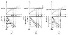
この場合、表示用画素4には各サブフレームに対応するデータ(駆動トランジスタ15がオンする電圧とオフする電圧)が書き込まれる。発光している際には有機EL素子14にはVDD−VSSの定電圧が印加されているため、例えば温度が上昇すると、有機EL素子14が同じ電圧でより電流を流すようになり、画面全体が明るくなる。その逆の場合では暗くなるため、所望の表示ができない。図3には、その様子が示されている。 In this case, data corresponding to each subframe (a voltage at which the
RGBの有機EL素子14及び18が、温度T0で図3(a)のような電圧電流特性を示したとすると、RGBの有機EL素子は、それぞれ電流Ir0、Ig0、Ib0を示す。したがって画素RGBそれぞれはIr0、Ig0、Ib0が最大電流となり、デジタル駆動ではこの範囲内で発光期間を制御することで多階調化を実現することになる。一般に有機EL素子は作製上の問題から、色、発光効率などの特性がある範囲で変動するため、この最大電流値を最大階調として与えると適切なホワイトバランスが維持できない。図3(a)はホワイトバランスを維持するため、最大電流を本来Ir0、Ig0、Ib0であるところを、Ir0’、Ig0’、Ib0’に制限し、それに対応するデータを最大階調データRmax0、Gmax0、Bmax0に割り当て直した例である。デジタル駆動が例えば8ビット以上の十分な階調を生成できれば、変換後も十分な階調を生成できるので、有機EL素子の特性が変動しても、ホワイトバランスを常に維持することができる。あらかじめ有機EL素子の特性変動量が明らかである場合には、RGB各色の発光面積をできる限り異ならせて、十分な階調表示を維持しつつ、ホワイトバランスを調整できることが望ましい。 If the RGB
ここで、例えば温度が上昇して温度T(>T0)となったとすると、RGB各色の有機EL素子はそれぞれ固有の特性に応じて電流が変化する。図3(b)は、有機EL素子に印加する電圧VDD−VSSを温度T0と同じにした場合の例であるが、それぞれの電流をIr、Ig、Ibとすると、この値が温度TでのRGB各色の最大電流となる。温度T(>T0)になった場合でも温度T0の場合と同じ表示データを入力し続ければ、ホワイトバランスが維持できず、色味や明るさの異なった映像となってしまう。そこで、図3(b)は、温度T0と同じホワイトバランスを生成する制限最大電流値Ir0’、Ig0’、Ib0’を維持し、制限最大階調を温度T0のときと異なるRmax、Gmax、Bmaxに変換している。図3(b)の場合には温度上昇に伴う電流上昇を、表示データを減少させることにより調整しているが、表示データが小さくなると階調再現範囲が狭くなる。そこで、図3(c)のように有機EL素子に印加する電圧VDD−VSSを小さくして表示データを調整すると制限最大階調Rmax、Gmax、Bmaxを本来の最大値へ近づけることができるため、ホワイトバランスを維持しつつも階調再現範囲を大きくすることができるため効果的である。 Here, for example, assuming that the temperature rises to a temperature T (> T0), the currents of the RGB organic EL elements change according to their specific characteristics. FIG. 3B shows an example in which the voltage VDD-VSS applied to the organic EL element is the same as the temperature T0. If the respective currents are Ir, Ig, and Ib, this value is obtained at the temperature T. It becomes the maximum current of each color of RGB. Even when the temperature T (> T0) is reached, if the same display data as in the case of the temperature T0 is continuously input, the white balance cannot be maintained, and an image having a different color and brightness is generated. Therefore, FIG. 3B shows that the maximum current values Ir0 ′, Ig0 ′, and Ib0 ′ that generate the same white balance as the temperature T0 are maintained, and the maximum maximum gradations that are different from those at the temperature T0 are Rmax, Gmax, and Bmax. Has been converted. In the case of FIG. 3B, the current increase due to the temperature increase is adjusted by decreasing the display data. However, when the display data becomes smaller, the gradation reproduction range becomes narrower. Therefore, if the display data is adjusted by reducing the voltage VDD-VSS applied to the organic EL element as shown in FIG. 3C, the limited maximum gradations Rmax, Gmax, Bmax can be brought close to the original maximum values. This is effective because the gradation reproduction range can be enlarged while maintaining the white balance.
また、図3(c)の方法は有機EL素子の発光効率及び電流の経時劣化による輝度の低下を補正する目的でも適用することが可能である。 Also, the method of FIG. 3C can be applied for the purpose of correcting the decrease in luminance due to the light emission efficiency of the organic EL element and the deterioration of current over time.
図4(a)に示されるように、有機EL素子の電圧電流特性は電流を流し続けていると時間とともにその特性が劣化し、同じ印加電圧に対して時刻tにおける電流Iは時刻t=0における電流I0より減少する。図4(b)に示されるようにより印加電圧を高くし、劣化した有機ELにより多くの電流が流れるように制御することができれば電流劣化を補正することができる。ただし、通常の映像を表示する限り、常時点灯する画素やほとんど点灯しない画素が同じパネル上に存在し、画素毎に劣化の進行が異なるため、図4(b)のように印加電圧を高くすると劣化の進行していない画素は所定以上の電流が流れることになる。しかし、これは劣化の進行の遅い画素に、より高い電流を流し、劣化を加速させる作用があるため、劣化が均一化されることが期待できる。 As shown in FIG. 4A, the voltage-current characteristic of the organic EL element deteriorates with time as current continues to flow, and the current I at time t is equal to time t = 0 for the same applied voltage. It decreases from the current I0 at. If the applied voltage is increased as shown in FIG. 4B and control can be performed so that more current flows through the deteriorated organic EL, the current deterioration can be corrected. However, as long as a normal image is displayed, pixels that are always lit or pixels that are hardly lit exist on the same panel, and the progress of deterioration differs for each pixel. Therefore, if the applied voltage is increased as shown in FIG. A current exceeding a predetermined value flows through a pixel in which deterioration has not progressed. However, this has the effect of causing a higher current to flow through the slow-degrading pixels and accelerating the degradation, so it can be expected that the degradation is made uniform.
次に、ホワイトバランスを維持し、また有機EL素子の電流劣化を補正する制御方法について説明する。 Next, a control method for maintaining white balance and correcting current deterioration of the organic EL element will be described.
まず、測定用画素5の動作について説明する。通常の表示時には、表示部1で映像が表示され、各画素の有機EL素子14には表示データに応じたパルス電流が流れている。また、測定用画素5にも表示部1の代表的なパルス電流を常に流しておく。なお、スイッチ20により、有機EL素子18のカソードを電源ラインVSSに接続しておく。 First, the operation of the
ここで、パルス電流とはVDD−VSSの電圧がある期間与えられた場合、この与えられた電圧でオンオフする電流を意味し、決められた電流がオンオフする電流ではない。代表的なパルス電流としては全画素データの平均値から算出したパルス電流を与えてもよいが、各画素の表示データを順にサンプルしてフレーム毎に異なる値を与えても良い。例えば、第nフレームでは第l行m列の画素のデータ、第n+1フレームでは第l行m+1列の画素データというように各フレームで異なる位置の画素データに対応するパルス電流を与えてもよい。 Here, when the voltage of VDD-VSS is given for a certain period, the pulse current means a current that turns on and off at the given voltage, and the determined current is not a current that turns on and off. As a typical pulse current, a pulse current calculated from an average value of all pixel data may be given. Alternatively, display data of each pixel may be sampled in order and a different value may be given for each frame. For example, pulse currents corresponding to pixel data at different positions in each frame may be applied, such as pixel data in the 1st row and m column in the nth frame and pixel data in the 1st row and m + 1 column in the n + 1th frame.
測定時には、別の測定用のパルス電流が測定用画素5に与えられ、RGBの測定用画素に流れる電流をコントローラ7で計測する。測定用画素5の制御は、表示用画素4と同様に、制御ライン12へパルス電圧を入力することで測定用有機EL素子18に本発明で意味するパルス電流を与えることができる。測定用有機EL素子18のカソードは、上述のように表示の際にはスイッチ20によりVSSへ接続するが、測定の際には電流ライン13へ接続する。測定用画素5は、RGB3色必要であるため、電流ライン13を3系統用意すれば一度にRGBの電流を測定できるが、RGBの測定タイミングをずらして例えばRGBの順番で、時分割でカソードを1系統の電流ライン13へ接続するようにすれば、電流ライン13やコントローラ7に内蔵する測定回路を1系統にできる。 At the time of measurement, another measurement pulse current is applied to the
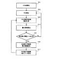
また、電源電圧VDDを固定値とし、VSSを変更できるものとすると制御フローは、図5のようになる。まず、ディスプレイが立ち上げられた際、VSSの初期化が行われ(S11)、VSSに初期値が設定される(S12)。この初期VSSで測定用画素の電流を測定する(S13)。この測定値とあらかじめ測定しておいた色座標と発光効率から所定のホワイトポイントで出力できる最大輝度を計算する(S14)。得られた最大輝度の計算値が設定しておいた輝度に対しプラスマイナス10%以内に収まっているかを判定し(S15)、収まっていれば前記ホワイトポイントを与える最大階調をRGB表示用画素の最大階調に設定し(S16)、RGB表示用画素の表示データを設定する(S17)。 Further, assuming that the power supply voltage VDD is a fixed value and VSS can be changed, the control flow is as shown in FIG. First, when the display is started up, VSS is initialized (S11), and an initial value is set in VSS (S12). The current of the pixel for measurement is measured with this initial VSS (S13). The maximum luminance that can be output at a predetermined white point is calculated from the measured value, the color coordinates measured in advance and the luminous efficiency (S14). It is determined whether or not the calculated value of the maximum luminance is within ± 10% of the set luminance (S15), and if it is, the maximum gradation that gives the white point is determined as an RGB display pixel. Is set to the maximum gradation (S16), and the display data of the RGB display pixels is set (S17).
S15の判定において、設定輝度に対しプラスマイナス10%から外れる場合には、S12に戻り再度VSSを設定し直す。例えば、輝度が足りない場合にはVSSをさらに下げてVDD−VSSを大きくし、明るい場合にはVSSを上げてVDD−VSSを小さくする。この動作を測定値が設定範囲内に収まるまで繰り返すことで所定のホワイトポイントを所定の輝度で実現する。 If it is determined in S15 that the set luminance deviates from ± 10%, the process returns to S12 and VSS is set again. For example, when the brightness is insufficient, VSS is further decreased to increase VDD-VSS, and when bright, VSS is increased to decrease VDD-VSS. By repeating this operation until the measured value falls within the set range, a predetermined white point is realized with a predetermined luminance.
図5のS15においては、目標達成範囲を10%以内としたが、この値は10%に限定されるものではなく、任意の値を設定できることはいうまでもない。 In S15 of FIG. 5, the target achievement range is set to be within 10%, but this value is not limited to 10%, and it goes without saying that an arbitrary value can be set.
表示データが設定された後も、測定用画素は測定をある周期で繰り返すことが好適である。例えば、周辺の温度が大きく上昇した場合、測定値は設定範囲を逸脱したデータを示し、この場合にVSSを上げて電流を減少させることができる。 Even after the display data is set, it is preferable that the measurement pixel repeats the measurement at a certain cycle. For example, when the ambient temperature rises greatly, the measured value indicates data that deviates from the set range, and in this case, the current can be decreased by increasing VSS.
さらに、測定用画素5には、表示部の代表的なパルス電流が与えられており、表示部1の平均的な画素劣化が反映されているはずである。そこで、測定用画素5について測定された駆動電流はこの劣化による影響も含まれている。したがって、図5による制御は、温度と経時劣化による電流変化を同時に補正していることになる。 Further, a representative pulse current of the display unit is given to the
さらに、測定用画素5に光センサーを備え、駆動電流に対する発光量を計測することで、発光効率の劣化を検出し、これを補正することもできる。そもそも測定用画素5の発光は表示に用いることが無いため不要であり、この発光領域に光センサーを配置して発光を遮断しても問題はない。むしろ、RGBの使用頻度の違い、劣化特性の違いなどによる色の変化を補正できるため有効である。 Furthermore, the
光センサーとしてはRGBに感度を有するフォトダイオードで形成された光(カラー)センサーを用いるとよい。図6A、図6Bに、光センサー22をセットに組み込んだ様子を示す。通常、表示部1はセットの筐体21から露出しており、表示パネル6のそれ以外の部分は筐体21に隠れて組み込まれる。ここで、図6AはRGB測定用画素にそれぞれ光(カラー)センサー22を配置した例である。この図6Aの光(カラー)センサー22はRGBの感度を有するものを用いても良いが、Rの測定用画素にはRに感度を有する光(カラー)センサーを、同様にGとBの測定用画素にはそれぞれG、Bに感度を有する光(カラー)センサーを用いてもよい。 As the light sensor, a light (color) sensor formed of a photodiode having sensitivity to RGB may be used. 6A and 6B show a state in which the
また、RGBに感度を有する光(カラー)センサー22を用い、図6Bのように測定用画素を表示用画素4と同様にRGBのマトリクス型配置として測定画素領域を少スペース化してもよい。この場合、測定用画素5の駆動トランジスタ19は、図6Bのように分割された測定用画素すべてに配置し、駆動トランジスタ19のゲート端子を共通の制御ライン12へ接続するか、駆動トランジスタ19を共有して、有機EL素子18をマトリクス型に分割する形態としてよい。 Alternatively, the light (color)
さらに、光(カラー)センサー22を用いて各色の輝度を測定できると、必ずしも電流を計測する必要はない。つまり、図7に示すように、図5の制御フローにおけるS13の電流計測を光(カラー)センサー22による各色の輝度計測(S23)に置き換える。このようにすると、光(カラー)センサー22の出力と輝度の関係は既知であるため、S14にて最大輝度を算出する際に電流から輝度への変換を行う必要がなくなり、補正を簡略化することができる。 Furthermore, if the luminance of each color can be measured using the light (color)
また、経時的な発光効率の劣化による輝度の低下も測定用画素に反映されているため、RGBの発光効率の異なる劣化に起因する色ずれを補正することも可能となる。 In addition, since a decrease in luminance due to deterioration in light emission efficiency over time is also reflected in the measurement pixels, it is possible to correct a color shift caused by different deterioration in RGB light emission efficiency.
本実施形態では、測定用有機EL素子18としてRGB各色用の1セットを設けたが、2セット以上を備えてもよい。複数の測定用画素5のセットをパネルの異なる位置に配置し、発光する期間をできる限り小さくして測定すれば、測定用画素5における発光を目立たせることもなく、表示パネル6の温度分布が把握できるであろう。つまり、測定用画素5と表示部1の温度の違いを推測することができ、より正確な補正が可能となる。 In the present embodiment, one set for each color of RGB is provided as the measurement organic EL element 18, but two or more sets may be provided. If a plurality of sets of
また、複数の測定用画素5のセットを用意すれば、例えば1つのセットには前述した表示部1の画素の平均的な動作を、別のセットには表示部1の画素のうち最も電流が流れている画素の動作をさせることによって、複数の劣化モデルを形成することができる。このため、劣化の程度の範囲を推測することができる。このようにすると、補正の程度をいくつか選択でき、ワーストケースで補正するか、平均的に補正するか、またその間とするなどを用途により選択できる。 If a set of a plurality of
1 表示部、2 データドライバ、3 ゲートドライバ、4 表示用画素、5 測定用画素、6 表示パネル、7 コントローラ、8 データライン、9 ゲートライン、12 制御ライン、13 電流ライン、14,18 有機EL素子、15,19 駆動トランジスタ、16 選択トランジスタ、17 保持容量、20 スイッチ、21 筐体、22 光(カラー)センサー。 DESCRIPTION OF
Claims (8)
Translated fromJapanese表示領域と異なる測定用画素内に形成され、表示領域に形成した有機EL素子と同じ工程で形成される測定用自発光素子と、
前記測定用画素内に形成され、前記測定用自発光素子に流れる駆動電流をオンオフにより制御する駆動トランジスタと、
前記駆動トランジスタのゲートに駆動電圧を供給する駆動電圧供給手段と、
前記駆動電圧供給手段により駆動電圧が供給されたときにおける測定用自発光素子の駆動状態を検出する駆動状態検出手段と、
を有し、
前記表示領域の自発光素子および測定用自発光素子は、赤(R)、緑(G)、青(B)の3色を有すると共に、
前記駆動状態検出手段は、RGB各色の測定用自発光素子に共通して1系統備えられ、RGBの測定タイミングをずらして時分割でRGB各色の測定用自発光素子と接続することで駆動状態を検出し、
前記表示領域の自発光素子および測定用自発光素子に印加する電圧VDD−VSSにおいて、電源電圧VDDを固定値とし、電源電圧VSSに初期値を設定することで、前記駆動状態検出手段におけるRGB各色の測定用自発光素子の駆動状態から、所定のホワイトポイントで出力できるRGB各色の最大輝度を求め、得られた最大輝度の値が設定値に対し所定範囲内に収まっているかを判定し、収まっていれば前記ホワイトポイントを与える最大階調をRGB表示用画素の最大階調に設定し、RGB表示用画素の表示データを設定し、前記最大輝度の値が設定値に対し所定範囲内に収まっていなければ、前記電源電圧VSSを輝度に応じて変更するようにして設定し直し、前記最大輝度の値が設定値に対し所定範囲内に収まるまで前記電源電圧VSSの設定し直す動作を繰り返すことで、所定のホワイトポイントを所定の輝度で実現する表示データ設定手段を有することを特徴とする表示装置。A display device in which self-luminous elements that emit light according to a driving current are arranged in a matrix in a display region,
A self-light emitting element for measurement formed in the same process as the organic EL element formed in the pixel for measurement different from the display area;
A drive transistor that is formed in the measurement pixel and controls a drive current flowing in the measurement light-emitting element by on / off; and
Drive voltage supply means for supplying a drive voltage to the gate of the drive transistor;
Drive state detection means for detecting the drive state of the light-emitting element for measurement when the drive voltage is supplied by the drive voltage supply means;
Have
The self-light-emitting element and the measurement self-light-emitting element in the display area have three colors of red (R), green (G), and blue (B),
The driving state detection means is provided in common with the measuring light-emitting elements for RGB colors, and is connected to the measuring light-emitting elements for RGB colors in a time division manner by shifting the RGB measurement timing. Detect
In the voltage VDD-VSS applied to the self-light-emitting element and the measurement self-light-emitting element in the display region, the power supply voltage VDD is set to a fixed value, and an initial value is set to the power supply voltage VSS, whereby each of the RGB colors in the drive state detection means The maximum luminance of each RGB color that can be output at a predetermined white point is obtained from the driving state of the measurement self-luminous element, and it is determined whether the obtained maximum luminance value is within a predetermined range with respect to the set value. If so, the maximum gradation that gives the white point is set to the maximum gradation of the RGB display pixel, the display data of the RGB display pixel is set,and the maximum luminance value falls within a predetermined range with respect to the set value. If not, the power supply voltage VSS is reset so as to change in accordance with the luminance, and the power supply voltage VSS is set until the maximum luminance value falls within a predetermined range with respect to a set value. By repeating the operation for resetting the pressure VSS, display device characterized by comprising a display data setting meansfor realizing a predetermined white point with a predetermined luminance.
前記駆動状態検出手段は、測定用自発光素子に流れる駆動電流を検出することを特徴とする表示装置。The display device according to claim 1,
The display device characterized in that the driving state detecting means detects a driving current flowing in the measuring self-luminous element.
前記駆動状態検出手段は、測定用自発光素子の発光量を検出することを特徴とする表示装置。The display device according to claim 1,
The display device characterized in that the driving state detection means detects the light emission amount of the light-emitting element for measurement.
さらに、
前記駆動状態検出手段において検出した駆動状態に基づいて、表示領域の各自発光素子に印加される電圧を補正する補正手段を有することを特徴とする表示装置。The display device according to any one of claims 1 to 3,
further,
A display device comprising correction means for correcting a voltage applied to each self-luminous element in the display area based on the drive state detected by the drive state detection means.
前記表示領域の自発光素子に供給する駆動電流は予め定められた電流であって、その供給時間が制御可能なデジタル駆動であり、
前記補正手段は、表示領域の自発光素子の正側または負側の電源電圧を変更することを特徴とする表示装置。The display device according to claim 4,
The driving current supplied to the self-luminous element in the display area is a predetermined current, and the driving time can be controlled by digital driving,
The display device according to claim 1, wherein the correction unit changes a power supply voltage on a positive side or a negative side of the self-luminous element in the display area.
前記駆動電圧供給手段は、表示領域の自発光素子に供給される駆動電流を代表する駆動電流を前記測定用自発光素子に供給するようにすることを特徴とする表示装置。In the display device according to any one of claims 1 to 5,
The display device characterized in that the drive voltage supply means supplies a drive current, which is representative of a drive current supplied to the self-light-emitting element in the display region, to the measurement self-light-emitting element.
前記駆動電圧供給手段は、測定用自発光素子に、前記表示領域の自発光素子と同様の駆動電圧を継続的に供給することで、前記駆動状態検出手段の検出値により表示領域の自発光素子の経時劣化を検出することを特徴とする表示装置。In the display device according to any one of claims 1 to 6,
The driving voltage supply means continuously supplies a driving voltage similar to that of the self-luminous element in the display area to the measuring self-luminous element, so that the self-luminous element in the display area is detected based on the detection value of the driving state detecting means. A display device characterized by detecting deterioration over time.
前記表示領域の自発光素子および測定用自発光素子は、有機EL素子であることを特徴とする表示装置。In the display device according to any one of claims 1 to 7,
The display device according to claim 1, wherein the self-luminous element and the measuring self-luminous element in the display region are organic EL elements.
Priority Applications (2)
| Application Number | Priority Date | Filing Date | Title |
|---|---|---|---|
| JP2006113367AJP5449641B2 (en) | 2006-04-17 | 2006-04-17 | Display device |
| US11/696,304US7817118B2 (en) | 2006-04-17 | 2007-04-04 | Display device |
Applications Claiming Priority (1)
| Application Number | Priority Date | Filing Date | Title |
|---|---|---|---|
| JP2006113367AJP5449641B2 (en) | 2006-04-17 | 2006-04-17 | Display device |
Publications (2)
| Publication Number | Publication Date |
|---|---|
| JP2007286341A JP2007286341A (en) | 2007-11-01 |
| JP5449641B2true JP5449641B2 (en) | 2014-03-19 |
Family
ID=38604379
Family Applications (1)
| Application Number | Title | Priority Date | Filing Date |
|---|---|---|---|
| JP2006113367AActiveJP5449641B2 (en) | 2006-04-17 | 2006-04-17 | Display device |
Country Status (2)
| Country | Link |
|---|---|
| US (1) | US7817118B2 (en) |
| JP (1) | JP5449641B2 (en) |
Families Citing this family (17)
| Publication number | Priority date | Publication date | Assignee | Title |
|---|---|---|---|---|
| KR100884791B1 (en)* | 2007-04-06 | 2009-02-23 | 삼성모바일디스플레이주식회사 | Organic light emitting display device and driving method thereof |
| JP4450012B2 (en)* | 2007-05-11 | 2010-04-14 | ソニー株式会社 | Display correction circuit for organic EL panel |
| JP2009109641A (en)* | 2007-10-29 | 2009-05-21 | Canon Inc | Drive circuit and active matrix display device |
| KR20090084444A (en)* | 2008-02-01 | 2009-08-05 | 삼성모바일디스플레이주식회사 | Organic light emitting display device and driving method thereof |
| KR101509118B1 (en) | 2008-10-27 | 2015-04-08 | 삼성디스플레이 주식회사 | OLED display, apparatus and method for generating correction information thereof |
| US8487844B2 (en)* | 2010-09-08 | 2013-07-16 | Semiconductor Energy Laboratory Co., Ltd. | EL display device and electronic device including the same |
| JP5733077B2 (en)* | 2011-07-26 | 2015-06-10 | セイコーエプソン株式会社 | ELECTRO-OPTICAL DEVICE, ELECTRO-OPTICAL DEVICE POWER SUPPLY METHOD, AND ELECTRONIC DEVICE |
| JP6131662B2 (en) | 2013-03-22 | 2017-05-24 | セイコーエプソン株式会社 | Display device and electronic device |
| KR20140122362A (en)* | 2013-04-09 | 2014-10-20 | 삼성디스플레이 주식회사 | Display device and driving method thereof |
| CN104732954B (en)* | 2013-12-20 | 2017-11-28 | 昆山国显光电有限公司 | The method of adjustment and adjustment system of AMOLED white balances |
| US10276095B2 (en) | 2014-08-21 | 2019-04-30 | Joled Inc. | Display device and method of driving display device |
| TWI543616B (en)* | 2015-07-21 | 2016-07-21 | 原相科技股份有限公司 | Method and apparatus for reducing fixed pattern noise of image sensor in digital domain |
| CN105304025B (en)* | 2015-12-08 | 2018-01-16 | 昆山工研院新型平板显示技术中心有限公司 | Organic Light Emitting Diode drive control method and system |
| US10930188B2 (en)* | 2017-11-23 | 2021-02-23 | Facebook Technologies, Llc | Feedback circuit for calibrating a current mode display |
| US10861380B2 (en) | 2018-05-14 | 2020-12-08 | Facebook Technologies, Llc | Display systems with hybrid emitter circuits |
| US10971061B2 (en) | 2019-01-11 | 2021-04-06 | Facebook Technologies, Llc | Control scheme for a scanning display |
| KR20240094643A (en)* | 2022-12-16 | 2024-06-25 | 엘지디스플레이 주식회사 | Display Device and Driving Method of the same |
Family Cites Families (14)
| Publication number | Priority date | Publication date | Assignee | Title |
|---|---|---|---|---|
| US6518962B2 (en)* | 1997-03-12 | 2003-02-11 | Seiko Epson Corporation | Pixel circuit display apparatus and electronic apparatus equipped with current driving type light-emitting device |
| TW480727B (en)* | 2000-01-11 | 2002-03-21 | Semiconductor Energy Laboratro | Semiconductor display device |
| JP2002304155A (en)* | 2001-01-29 | 2002-10-18 | Semiconductor Energy Lab Co Ltd | Light-emitting device |
| JP2002258792A (en)* | 2001-02-28 | 2002-09-11 | Matsushita Electric Ind Co Ltd | Display device |
| JP2002351403A (en)* | 2001-05-30 | 2002-12-06 | Toshiba Corp | Image display device |
| US6677958B2 (en)* | 2001-06-22 | 2004-01-13 | Eastman Kodak Company | Method for calibrating, characterizing and driving a color flat panel display |
| JP2003317944A (en)* | 2002-04-26 | 2003-11-07 | Seiko Epson Corp | Electro-optical devices and electronic equipment |
| JP4027284B2 (en)* | 2002-07-26 | 2007-12-26 | キヤノン株式会社 | Manufacturing method of image display device |
| JP3749993B2 (en)* | 2002-08-14 | 2006-03-01 | ローム株式会社 | Organic EL drive circuit and organic EL display device using the same |
| JP2004272244A (en)* | 2003-02-24 | 2004-09-30 | Barco Nv | Fixed format emissive display, its design using a computing device, and a computer program product |
| JP2004258489A (en)* | 2003-02-27 | 2004-09-16 | Seiko Epson Corp | Electro-optical devices and electronic equipment |
| JP2005331891A (en) | 2004-05-21 | 2005-12-02 | Eastman Kodak Co | Display apparatus |
| JP4958392B2 (en) | 2004-08-11 | 2012-06-20 | グローバル・オーエルイーディー・テクノロジー・リミテッド・ライアビリティ・カンパニー | Display device |
| JP2007240802A (en)* | 2006-03-08 | 2007-09-20 | Sony Corp | Spontaneous light emission display device, white balance adjusting device, and program |
- 2006
- 2006-04-17JPJP2006113367Apatent/JP5449641B2/enactiveActive
- 2007
- 2007-04-04USUS11/696,304patent/US7817118B2/enactiveActive
Also Published As
| Publication number | Publication date |
|---|---|
| US20070242002A1 (en) | 2007-10-18 |
| JP2007286341A (en) | 2007-11-01 |
| US7817118B2 (en) | 2010-10-19 |
Similar Documents
| Publication | Publication Date | Title |
|---|---|---|
| JP5449641B2 (en) | Display device | |
| US7696965B2 (en) | Method and apparatus for compensating aging of OLED display | |
| JP4036142B2 (en) | Electro-optical device, driving method of electro-optical device, and electronic apparatus | |
| US7605792B2 (en) | Driving method and circuit for automatic voltage output of active matrix organic light emitting device and data drive circuit using the same | |
| JP5761776B2 (en) | Organic light emitting display device and driving method thereof | |
| US7321350B2 (en) | Image display | |
| US11594187B2 (en) | Display device and method of driving the same | |
| JP5384844B2 (en) | Optical sensor and flat panel display using the same | |
| US11222597B2 (en) | Display device and method for controlling same | |
| JP5015714B2 (en) | Pixel circuit | |
| US20080246701A1 (en) | Organic light emitting display and its driving method | |
| US20080231557A1 (en) | Emission control in aged active matrix oled display using voltage ratio or current ratio | |
| JP2008122516A (en) | Display device and video signal processing system | |
| US20070290947A1 (en) | Method and apparatus for compensating aging of an electroluminescent display | |
| KR100707637B1 (en) | Light emitting display device and control method thereof | |
| US10796629B2 (en) | Display panel voltage drop correction | |
| KR100741977B1 (en) | Organic electroluminescent display and driving method thereof | |
| US9001099B2 (en) | Image display and image display method | |
| KR101142281B1 (en) | Organic electro luminescent display and driving method of the same | |
| US20080231566A1 (en) | Minimizing dark current in oled display using modified gamma network | |
| CN104464591A (en) | Image signal processing circuit, image signal processing method, and display device | |
| US20080252567A1 (en) | Active Matrix Display Device | |
| US12205544B2 (en) | Display device | |
| KR100667079B1 (en) | Auto Brightness Organic Electroluminescent Display | |
| JP2007233401A (en) | Electro-optical device, driving method of electro-optical device, and electronic apparatus |
Legal Events
| Date | Code | Title | Description |
|---|---|---|---|
| A621 | Written request for application examination | Free format text:JAPANESE INTERMEDIATE CODE: A621 Effective date:20090122 | |
| RD03 | Notification of appointment of power of attorney | Free format text:JAPANESE INTERMEDIATE CODE: A7423 Effective date:20100319 | |
| A711 | Notification of change in applicant | Free format text:JAPANESE INTERMEDIATE CODE: A711 Effective date:20100520 | |
| A977 | Report on retrieval | Free format text:JAPANESE INTERMEDIATE CODE: A971007 Effective date:20110920 | |
| A131 | Notification of reasons for refusal | Free format text:JAPANESE INTERMEDIATE CODE: A131 Effective date:20110927 | |
| A521 | Request for written amendment filed | Free format text:JAPANESE INTERMEDIATE CODE: A523 Effective date:20111208 | |
| A131 | Notification of reasons for refusal | Free format text:JAPANESE INTERMEDIATE CODE: A131 Effective date:20120124 | |
| A521 | Request for written amendment filed | Free format text:JAPANESE INTERMEDIATE CODE: A523 Effective date:20120319 | |
| A02 | Decision of refusal | Free format text:JAPANESE INTERMEDIATE CODE: A02 Effective date:20120529 | |
| A521 | Request for written amendment filed | Free format text:JAPANESE INTERMEDIATE CODE: A523 Effective date:20120822 | |
| A911 | Transfer to examiner for re-examination before appeal (zenchi) | Free format text:JAPANESE INTERMEDIATE CODE: A911 Effective date:20120829 | |
| A912 | Re-examination (zenchi) completed and case transferred to appeal board | Free format text:JAPANESE INTERMEDIATE CODE: A912 Effective date:20121207 | |
| A61 | First payment of annual fees (during grant procedure) | Free format text:JAPANESE INTERMEDIATE CODE: A61 Effective date:20131225 | |
| R150 | Certificate of patent or registration of utility model | Ref document number:5449641 Country of ref document:JP Free format text:JAPANESE INTERMEDIATE CODE: R150 Free format text:JAPANESE INTERMEDIATE CODE: R150 | |
| R250 | Receipt of annual fees | Free format text:JAPANESE INTERMEDIATE CODE: R250 | |
| R250 | Receipt of annual fees | Free format text:JAPANESE INTERMEDIATE CODE: R250 | |
| R250 | Receipt of annual fees | Free format text:JAPANESE INTERMEDIATE CODE: R250 | |
| R250 | Receipt of annual fees | Free format text:JAPANESE INTERMEDIATE CODE: R250 | |
| R250 | Receipt of annual fees | Free format text:JAPANESE INTERMEDIATE CODE: R250 | |
| R250 | Receipt of annual fees | Free format text:JAPANESE INTERMEDIATE CODE: R250 | |
| R250 | Receipt of annual fees | Free format text:JAPANESE INTERMEDIATE CODE: R250 | |
| R250 | Receipt of annual fees | Free format text:JAPANESE INTERMEDIATE CODE: R250 | |
| R250 | Receipt of annual fees | Free format text:JAPANESE INTERMEDIATE CODE: R250 |