JP5449301B2 - Apparatus, system, and method for providing tactile sensation - Google Patents
Apparatus, system, and method for providing tactile sensationDownload PDFInfo
- Publication number
- JP5449301B2 JP5449301B2JP2011267054AJP2011267054AJP5449301B2JP 5449301 B2JP5449301 B2JP 5449301B2JP 2011267054 AJP2011267054 AJP 2011267054AJP 2011267054 AJP2011267054 AJP 2011267054AJP 5449301 B2JP5449301 B2JP 5449301B2
- Authority
- JP
- Japan
- Prior art keywords
- vibrotactile
- user
- virtual
- mass
- unit
- Prior art date
- Legal status (The legal status is an assumption and is not a legal conclusion. Google has not performed a legal analysis and makes no representation as to the accuracy of the status listed.)
- Expired - Lifetime
Links
Images


Classifications
- G—PHYSICS
- G06—COMPUTING OR CALCULATING; COUNTING
- G06F—ELECTRIC DIGITAL DATA PROCESSING
- G06F3/00—Input arrangements for transferring data to be processed into a form capable of being handled by the computer; Output arrangements for transferring data from processing unit to output unit, e.g. interface arrangements
- G06F3/01—Input arrangements or combined input and output arrangements for interaction between user and computer
- G06F3/016—Input arrangements with force or tactile feedback as computer generated output to the user
- G—PHYSICS
- G06—COMPUTING OR CALCULATING; COUNTING
- G06F—ELECTRIC DIGITAL DATA PROCESSING
- G06F3/00—Input arrangements for transferring data to be processed into a form capable of being handled by the computer; Output arrangements for transferring data from processing unit to output unit, e.g. interface arrangements
- G06F3/01—Input arrangements or combined input and output arrangements for interaction between user and computer
- G06F3/011—Arrangements for interaction with the human body, e.g. for user immersion in virtual reality
- G06F3/014—Hand-worn input/output arrangements, e.g. data gloves
- G—PHYSICS
- G06—COMPUTING OR CALCULATING; COUNTING
- G06F—ELECTRIC DIGITAL DATA PROCESSING
- G06F3/00—Input arrangements for transferring data to be processed into a form capable of being handled by the computer; Output arrangements for transferring data from processing unit to output unit, e.g. interface arrangements
- G06F3/01—Input arrangements or combined input and output arrangements for interaction between user and computer
- G06F3/048—Interaction techniques based on graphical user interfaces [GUI]
- G06F3/0484—Interaction techniques based on graphical user interfaces [GUI] for the control of specific functions or operations, e.g. selecting or manipulating an object, an image or a displayed text element, setting a parameter value or selecting a range
- G—PHYSICS
- G10—MUSICAL INSTRUMENTS; ACOUSTICS
- G10H—ELECTROPHONIC MUSICAL INSTRUMENTS; INSTRUMENTS IN WHICH THE TONES ARE GENERATED BY ELECTROMECHANICAL MEANS OR ELECTRONIC GENERATORS, OR IN WHICH THE TONES ARE SYNTHESISED FROM A DATA STORE
- G10H1/00—Details of electrophonic musical instruments
- G10H1/32—Constructional details
- G10H1/34—Switch arrangements, e.g. keyboards or mechanical switches specially adapted for electrophonic musical instruments
- G—PHYSICS
- G10—MUSICAL INSTRUMENTS; ACOUSTICS
- G10L—SPEECH ANALYSIS TECHNIQUES OR SPEECH SYNTHESIS; SPEECH RECOGNITION; SPEECH OR VOICE PROCESSING TECHNIQUES; SPEECH OR AUDIO CODING OR DECODING
- G10L15/00—Speech recognition
- G10L15/22—Procedures used during a speech recognition process, e.g. man-machine dialogue
- G—PHYSICS
- G10—MUSICAL INSTRUMENTS; ACOUSTICS
- G10H—ELECTROPHONIC MUSICAL INSTRUMENTS; INSTRUMENTS IN WHICH THE TONES ARE GENERATED BY ELECTROMECHANICAL MEANS OR ELECTRONIC GENERATORS, OR IN WHICH THE TONES ARE SYNTHESISED FROM A DATA STORE
- G10H2220/00—Input/output interfacing specifically adapted for electrophonic musical tools or instruments
- G10H2220/155—User input interfaces for electrophonic musical instruments
- G10H2220/321—Garment sensors, i.e. musical control means with trigger surfaces or joint angle sensors, worn as a garment by the player, e.g. bracelet, intelligent clothing
- G—PHYSICS
- G10—MUSICAL INSTRUMENTS; ACOUSTICS
- G10L—SPEECH ANALYSIS TECHNIQUES OR SPEECH SYNTHESIS; SPEECH RECOGNITION; SPEECH OR VOICE PROCESSING TECHNIQUES; SPEECH OR AUDIO CODING OR DECODING
- G10L15/00—Speech recognition
- G10L15/22—Procedures used during a speech recognition process, e.g. man-machine dialogue
- G10L2015/225—Feedback of the input speech
Landscapes
- Engineering & Computer Science (AREA)
- General Engineering & Computer Science (AREA)
- Theoretical Computer Science (AREA)
- Physics & Mathematics (AREA)
- Human Computer Interaction (AREA)
- General Physics & Mathematics (AREA)
- Acoustics & Sound (AREA)
- Multimedia (AREA)
- Health & Medical Sciences (AREA)
- Audiology, Speech & Language Pathology (AREA)
- Computational Linguistics (AREA)
- User Interface Of Digital Computer (AREA)
- Position Input By Displaying (AREA)
- Manipulator (AREA)
Description
Translated fromJapanese 米国特許文献
第4,414,948号 11/1983 ツァルディアンスキー(Zarudiansky)
第5,184,319号 02/1990 クラマー(Kramer)
他の刊行物
C. J. Hasser,「力を反映する擬人化ハンドマスター("Force-reflecting Anthropomorphic Hand masters")」,Interim Report, Air ForceMaterial Command, Wright-Patterson Air Force Base, July 1995.
K. Kaczmarek and P/Bach-y-rita,「触覚装置("Tacti1e Displays")」, in Advanced Interface Design and Virtual Environment; W. Barfieldand T. Furness III Editors, Oxford University Press,1993.
D. A. Kontarinis and R. D. Howe,「遠隔オペレータへの高周波触覚情報の表示("Display ofHigh-frequency Tati1e Information to Teleoperators")」, Proceedings of the SPIE- The International Society for Optical Engineering, 1993, Vol.2057, pp.40-50.
N. J. M. Patric, T. B. Sheridan, M. J. Massimino and B. A. Marcus,「遠隔環境との相互作用のための非反応性指先触覚ディスプレイの設計および試験("Design and Testing of a Non-reactive Fingertip Tacti1eDisplay for Interaction with Remote Environments")」, Proceedings of the SPIE- The International Society for Optical Engineering, 1991,Vol. 1387,pp.215-222.U.S. Pat.No. 4,414,948 11/1983 Zarudiansky
No.5,184,319 02/1990 Kramer
Other publications
CJ Hasser, “Force-reflecting Anthropomorphic Hand masters”, Interim Report, Air ForceMaterial Command, Wright-Patterson Air Force Base, July 1995.
K. Kaczmarek and P / Bach-y-rita, "Tacti1e Displays", in Advanced Interface Design and Virtual Environment; W. Barfieldand T. Furness III Editors, Oxford University Press, 1993.
DA Kontarinis and RD Howe, "Display of High-frequency Tati1e Information to Teleoperators", Proceedings of the SPIE- The International Society for Optical Engineering, 1993, Vol. 2057, pp. 40-50.
NJM Patric, TB Sheridan, MJ Massimino and BA Marcus, “Design and Testing of a Non-reactive Fingertip Tacti1eDisplay for Interaction with Remote Environments” ) ", Proceedings of the SPIE- The International Society for Optical Engineering, 1991, Vol. 1387, pp.215-222.
本発明は人間−機械インターフェースに関し、特に、使用者に対して触感を提供するインターフェースに関する。 The present invention relates to a human-machine interface, and more particularly to an interface that provides tactile sensation to a user.
仮想現実(バーチャルリアリティー;VR)は、コンピュータによって創造された、使用者がリアルタイムで多感覚的に相互作用する没入環境である。典型的には、これらの相互作用には視覚的フィードバック、音、力および触覚のフィードバック(即ち反射)、臭い、更には味覚を介する人間の感覚の幾つかまたは全てが含まれる。没入的現実の鍵は、彼または彼女の手が仮想物体を相互作用的に操作する能力である。残念ながら、現存の商業的バーチャルリアリティー装置の殆どは手で感知する装置を用いているが、これは触覚的なフィードバックを与えない。にもかかわらず、力および触覚の情報を使用者の手に与えるための手段を提供する幾つかの努力が行われてきた。力の情報とは、手の選択された部分(例えば指に対して)、一組の力を適用することを意味する。触覚情報とは、手の選択された部分(例えば指先パッド)に対して、剌激(例えば振動)を与えることを意味する。この剌激は、例えば接触時における表面の手触りまたは動的状態をシミュレートできるであろう。力を反映する現存の数少ない装置の例は、EXOS SAFiRETM(登録商標)、ルッツガー(Rutgers)大学におけるマスターIIハンドマスター装置、PERCRO力反映ハンドマスター、およびサルコス(Sarcos)T0PS力反映ハンドマスターである。既に開発された幾つかの触覚フィードバック装置には、PERCRO位置検知および触覚フィードバックハンドマスター、およびEXOSTouchMasterTM(登録商標)が含まれる。Virtual reality (VR) is an immersive environment created by computers where users interact multi-sensory in real time. Typically, these interactions include some or all of human feedback via visual feedback, sound, force and haptic feedback (ie, reflex), odor, and even taste. The key to immersive reality is the ability of his or her hands to manipulate virtual objects interactively. Unfortunately, most existing commercial virtual reality devices use hand-sensing devices that do not provide tactile feedback. Nevertheless, several efforts have been made to provide means for providing force and tactile information to the user's hand. Force information means applying a set of forces to a selected part of the hand (eg, against a finger). The tactile information means giving a stimulus (for example, vibration) to a selected part (for example, a fingertip pad) of the hand. This excitement could, for example, simulate the surface feel or dynamic state upon contact. Examples of the few existing devices that reflect force are the EXOS SAFiRE™ , the Master II hand master device at the University of Rutgers, the PERCRO force reflecting hand master, and the Sarcos T0PS force reflecting hand master . Some haptic feedback devices already developed include PERCRO position sensing and haptic feedback handmaster, and EXOSTouchMaster™ .
バーチャルリアリティーは、使用者/操作者の人間に対して力および触覚情報をフィードバックすることが望まれている唯一の分野ではない。もう一つの通常の領域は、遠隔ロボット工学(telerobotics)である。上記で述べた装置の幾つかは、遠隔ロボット工学のインターフェースとして用いられることも多い。文献中に記載された、遠隔ロボット工学用に特別に設計されたフィードバック装置の幾つかの例には、コンタリニス等(Kontariniset al)が開発した触覚形状の検知および表示システム、パトリック等(Patricket al)が使用した音声コイルに基づく触覚フィードバック装置、およびカクズマレク(Kaczmarek)およびバッハ-y-リタ(Nach-y-rita)によって開発されたピンをベースとする触覚表示アレイが含まれる。本発明の振動触覚ユニットにおける他の応用には、ジェスチャー認識、音楽発生、娯楽および医療の応用が含まれるが、これらに限定されるものではない。 Virtual reality is not the only field where it is desired to feed back force and haptic information to the user / operator's human. Another common area is telebotics. Some of the devices described above are often used as remote robotics interfaces. Some examples of feedback devices specifically designed for remote robotics described in the literature include haptic shape detection and display systems developed by Kontariniset al, Patrick et al. Includes a tactile feedback device based on the voice coil used by and the pin-based tactile display array developed by Kaczmarek and Nach-y-rita. Other applications in the vibrotactile unit of the present invention include, but are not limited to, gesture recognition, music generation, entertainment and medical applications.
理想的な場合は、完全な力および触覚のフィードバックを使用者に与えて、バーチャルリアリティーまたは遠隔ロボット光学を可能な限り現実的にするのが望ましい。残念ながら、力をフィードバックする殆どの装置は、複雑で重く、高価で、しかも設置および除去が困難である。多くの触覚フィードバックの解決策もまた、面倒かつ複雑で、もろいものである。加えて、皮膚に直接接触して装着された小さい音声コイルのような、文献に記載されている幾つかの触覚フィードバック装置は、わずか数秒の動作で皮膚を麻痺させ、フィードバック装置としての効果が無くなる傾向がある。 In the ideal case, it is desirable to give the user full force and tactile feedback to make the virtual reality or remote robot optics as realistic as possible. Unfortunately, most devices that provide force feedback are complex, heavy, expensive, and difficult to install and remove. Many tactile feedback solutions are also cumbersome, complex and fragile. In addition, some haptic feedback devices described in the literature, such as a small voice coil mounted in direct contact with the skin, numb the skin in just a few seconds and become ineffective as a feedback device Tend.
本発明の目的は、相互作用コンピュータアプリケーション、遠隔ロボット工学、ジェスチャー認識、音楽発生、娯楽、医療的応用などのような領域に用いることができる、人間/機械インターフェースである。本発明の他の目的は、使用者が感じることができる振動を発生する「マス運動アクチュエータ(mass-moving actuator」によって動かされるマスである。本発明の更に別の目的は、駆動信号を発生させて、使用者の仮想状態または物理的状態の結果として、または環境条件の結果として振動を発生させることである。本発明の更にもう一つの目的は、皮膚の物理的刺激受容体と同様に、検知する身体部分の骨格構造を振動させてフィードバックを与えることである。本発明の更に別の目的は、振動装置を複雑に駆動させることである。 The object of the present invention is a human / machine interface that can be used in areas such as interactive computer applications, remote robotics, gesture recognition, music generation, entertainment, medical applications and the like. Another object of the present invention is a mass that is moved by a “mass-moving actuator” that generates vibrations that can be felt by the user, yet another object of the present invention is to generate a drive signal. Another object of the present invention is to generate vibrations as a result of the user's virtual or physical state or as a result of environmental conditions. It is to provide feedback by vibrating the skeletal structure of the body part to be detected, and yet another object of the present invention is to drive the vibration device in a complicated manner.
使用者が感じる触覚感覚は、固定手段によって使用者の検知する身体部分の上に装着され、または機能的にこれと関連して装着された振動触覚ユニットによって発生される。一実施例において、振動触覚装置は、マス運動アクチュエータのシャフトに偏心して接続されたマス(即ち、マスの中心は回転軸から外れている)を具備している。マスアクチュエータに電圧を与えるとシャフトが回転し、これによって偏心マスが回転する。この回転するマスは、これに対応した回転する力ベクトルを生じる。遅く回転する力ベクトルは、一連の個々の刺激のように感じられる。少数の迅速な回転については、回転する力ベクトルは単一の衝撃のように感じられる。我々は、力ベクトルの変化(即ち、方向または大きさ)を言うために、「振動」の用語を用いる。振動の例には、単一の衝撃、サイン曲線の力の大きさ、および他の関数の力ベクターが含まれるが、これらに限定されない。使用者の検知する身体部分が振動触覚ユニットによって誘起される振動を受けるときに、使用者が受け取る感じを言うために、我々は「触覚感覚」の用語を用いる。 The tactile sensation felt by the user is generated by a vibrotactile unit mounted on or functionally associated with a body part sensed by the user by a fixing means. In one embodiment, the vibrotactile device comprises a mass that is eccentrically connected to the shaft of the mass motion actuator (ie, the center of the mass is off the axis of rotation). When a voltage is applied to the mass actuator, the shaft rotates, whereby the eccentric mass rotates. The rotating mass generates a corresponding rotating force vector. Slowly rotating force vectors feel like a series of individual stimuli. For a few quick turns, the rotating force vector feels like a single impact. We use the term “vibration” to refer to the change (ie, direction or magnitude) of the force vector. Examples of vibrations include, but are not limited to, single impacts, sine curve force magnitudes, and other function force vectors. We use the term “tactile sensation” to refer to the feeling a user receives when the body part that the user senses is subjected to vibration induced by the vibrotactile unit.
信号処理装置は状態信号を解釈して、マス運動アクチュエータを駆動するための駆動信号を発生する。状態信号の可変成分は、物理的なもの(例えば測定されたもの)でもよく、または仮想のもの(例えばシミュレートされたまたは内部で作成された)でもよく、これらは時間と共に変化するものでもよく(例えば状態変数はプロセスを表してもよい)、それらは整数値でもよく(例えば、二元性のまたは不連続な)、または実数(例えば連続的)であってもよい。信号処理装置は、状態信号を解釈し更に加工するコンピュータを具備してもよく、または具備しなくてもよい。この信号処理装置は信号ドライバを具備し、該ドライバは振動触覚ユニットにエネルギーを供給する駆動信号、または該ユニットが消費するエネルギーを制御する駆動信号を生じる。エネルギー源は電気的、空気圧式、水圧式、および燃焼式のものでよいが、これらに限定されない。ドライバは、閉ループ制御のための電流アンプおよびセンサを有する電気モータコントローラ、加圧液体またはガスの量を制御する流量弁、燃焼エンジンへの燃料の量を制御する流量弁などであり得るが、これらに限定されない。このような信号処理装置およびマス運動アクチュエータの詳細は、当業者の常識である。 The signal processor interprets the status signal and generates a drive signal for driving the mass motion actuator. The variable component of the state signal may be physical (eg, measured) or virtual (eg, simulated or created internally), and these may vary over time. (Eg, state variables may represent processes), they may be integer values (eg, binary or discontinuous), or real numbers (eg, continuous). The signal processing device may or may not include a computer that interprets and further processes the status signal. The signal processing device includes a signal driver that generates a drive signal that supplies energy to the vibrotactile unit or that controls the energy consumed by the unit. The energy source may be, but is not limited to, electrical, pneumatic, hydraulic, and combustion. The driver can be an electric motor controller with a current amplifier and sensor for closed-loop control, a flow valve that controls the amount of pressurized liquid or gas, a flow valve that controls the amount of fuel to the combustion engine, etc. It is not limited to. Details of such signal processing devices and mass motion actuators are common knowledge of those skilled in the art.
状態信号は、種々の条件に応答して発生され得る。一つの実施例では、使用者の物理的条件および/または使用者の環境を測定する1以上のセンサ類が、物理的状態信号の1以上の成分を発生し得る。他の実施例では、コンピュータシミュレーションが、シミュレートされた(例えば仮想の)状態または条件から、仮想状態信号の1以上の成分を決定し得る。仮想状態は、物理的状態によって任意に影響され得る。仮想状態にはコンピュータシステムまたはタイミングシステムが作成できる如何なるものも含まれ、これには以前の事象からの固定された時間、シミュレーションにおける1以上の仮想物体の位置、速度、加速(または他のダイナミック量)、シミュレーションにおける二つの仮想物体の衝突、コンピュータのジョブまたは処理の開始または終了、他の処理またはシミュレーションによるフラッグの設定、状態の組合せなどが含まれるが、これらに限定されるものではない。仮想状態信号は、仮想状態変数の機械読み取り可能な測定である。 The status signal can be generated in response to various conditions. In one embodiment, one or more sensors that measure the user's physical conditions and / or the user's environment may generate one or more components of the physical state signal. In other examples, a computer simulation may determine one or more components of the virtual state signal from a simulated (eg, virtual) state or condition. The virtual state can be arbitrarily affected by the physical state. Virtual states include anything that a computer system or timing system can create, including a fixed time from a previous event, the position, velocity, acceleration (or other dynamic amount) of one or more virtual objects in the simulation. ), The collision of two virtual objects in a simulation, the start or end of a computer job or process, the setting of flags by other processes or simulations, a combination of states, etc., but is not limited thereto. A virtual state signal is a machine-readable measurement of a virtual state variable.
物理状態信号は、物理状態変数から測定される。これらの変数は、使用者の身体部分の物理的状態または使用者の物理的環境に関連している。物理状態変数には、環境における何れかの測定可能なパラメータ、または使用者の身体部分に関連した何れかの測定可能なパラメータが含まれる。環境における測定可能な物理的パラメータの幾つかの例には、身体部分の状態、環境における物体の位置、環境における物体に付与されるエネルギーの量、環境における物体の存在、物体の化学的状態、および環境における温度等が含まれるが、これらに限定されるものではない。身体部分の状態には、他の身体部分または環境中の点に対する当該身体部分の物理的位置、速度または加速が含まれる。また、身体部分の状態は如何なる身体機能をも含み得るが、ここでの測定された状態信号には脳波計(EEC)、心電図(ECG)、筋電計(EMG)、エレクトロオプティグラフまたは凝視センサ(eye-gaze sensor)、並びに関節角度、心拍速度、皮膚または皮下の温度、血圧、血中酸素(または何れかの測定可能な血液化学成分)の濃度、消化作用、ストレスレベル、音声活動または音声認識などを測定するセンサ類からの出力が含まれる。使用者の音声は、測定された物理的状態変数を構成することができ、ここでは使用者が話した言葉が検知および/または認識されて、対応する駆動信号を発生する。物理的状態信号は、物理的状態変数の機械読み取り可能な測定値である。 The physical state signal is measured from the physical state variable. These variables relate to the physical state of the user's body part or the user's physical environment. The physical state variable includes any measurable parameter in the environment or any measurable parameter associated with the user's body part. Some examples of measurable physical parameters in the environment include the state of the body part, the position of the object in the environment, the amount of energy imparted to the object in the environment, the presence of the object in the environment, the chemical state of the object, And the temperature in the environment are included, but are not limited thereto. The state of the body part includes the physical position, velocity or acceleration of the body part relative to other body parts or points in the environment. In addition, the state of the body part can include any body function, but the measured state signal here includes an electroencephalograph (EEC), an electrocardiogram (ECG), an electromyograph (EMG), an electrooptigraph or a gaze sensor. (eye-gaze sensor), as well as joint angle, heart rate, skin or subcutaneous temperature, blood pressure, blood oxygen (or any measurable blood chemistry) concentration, digestion, stress level, voice activity or voice Includes outputs from sensors that measure recognition and the like. The user's voice can constitute a measured physical state variable, where words spoken by the user are detected and / or recognized to generate a corresponding drive signal. A physical state signal is a machine-readable measurement of a physical state variable.
状態信号が信号処理装置に与えられ、該処理装置は状態を解釈して、振動触覚ユニットを如何にして駆動するか、また何時駆動するかを決定する。信号処理装置は、状態信号から解釈される事象に応答し得る駆動信号を発生する。事象の例には、接触、ジェスチャー、話された言葉、パニックまたは気絶の発作などが含まれる。状態信号の解釈は二値的なもの、即ち、二つの値の間での状態の単純な変化あってもよく、そうでなくてもよい。二値的事象の一例は、二つの仮想物体または現実の物体の間の接触vs.非接触である。解釈のプロセスは、状態変数成分の何等かの一般的関数を含み得る。解釈関数は、整数または実数値の出力制御値を生じ得る。非二元値の解釈出力は、典型的には、非二元的駆動信号を生じるような信号処理装置に関連している。 A status signal is provided to the signal processor, which interprets the status and determines how and when to drive the vibrotactile unit. The signal processor generates a drive signal that can respond to an event interpreted from the status signal. Examples of events include touches, gestures, spoken words, panic or fainting attacks. The interpretation of the state signal may be binary, i.e. there may or may not be a simple change of state between the two values. An example of a binary event is contact vs. non-contact between two virtual or real objects. The process of interpretation may include any general function of state variable components. Interpretation functions can produce integer or real value output control values. The non-binary interpretation output is typically associated with a signal processor that produces a non-binary drive signal.
駆動信号の関数形態を変化させることにより、振動触覚装置が発生するフィードバックの種類もまた変化し得る。この装置は、単一または複数の振動触覚ユニットからの非二値性信号として定義される、複雑な触覚を発生させることができる。複雑な触覚感覚の例には、(1)振動の振幅を変化させて経時的に均一でないプロファイルをもたせること、(2)振動の周波数を変化させること、(3)衝撃の持続時問を変化させること、(4)振幅および周波数の組合せを変化させること、(5)2以上の振動触覚ユニットを、均一または不均一な振幅プロファイルで振動させること、(6)複数の振動触覚ユニットを異なった振幅または周波数プロファイルでシーケンスすること等が含まれる。 By changing the functional form of the drive signal, the type of feedback generated by the vibrotactile device can also change. This device can generate complex haptics, defined as non-binary signals from single or multiple vibrotactile units. Examples of complex tactile sensations include: (1) changing the amplitude of vibration to have a non-uniform profile over time, (2) changing the frequency of vibration, and (3) changing the duration of impact. (4) changing the combination of amplitude and frequency, (5) vibrating two or more vibrotactile units with a uniform or non-uniform amplitude profile, (6) different vibrotactile units differently This includes sequencing with amplitude or frequency profiles.
振動または衝撃の周波数および振幅は、マス運動アクチュエータに供給される駆動信号を変更することによって変化させることができる。周波数および振幅はまた、マスを増大し、または旋回半径を変化させること(例えばその偏心性を変化させる)によって制御することができる。使用者が感じる周波数の感覚は、可変周波数で振動触覚ユニットに与えられる出力(パワー)を変調することによって、振幅とは独立に変化させることができる。この技術は振幅変調と呼ばれており、当業者の常識である。この周波数および振幅における変化は、複雑な複合形態または他の形態の情報を使用者に伝達するために使用することができる。 The frequency or amplitude of the vibration or shock can be changed by changing the drive signal supplied to the mass motion actuator. The frequency and amplitude can also be controlled by increasing the mass or changing the turning radius (eg, changing its eccentricity). The frequency sensation felt by the user can be varied independently of the amplitude by modulating the output (power) applied to the vibrotactile unit at a variable frequency. This technique is called amplitude modulation and is common knowledge of those skilled in the art. This change in frequency and amplitude can be used to convey complex complex or other forms of information to the user.
センサは、使用者に感得される振動の周波数および振幅を決定するために、振動触覚ユニットまたは検知する身体部分に装着することができる。この情報を用いるフィードバック制御ループを加えることにより、周波数および振幅をより緊密に制御し、または全体の振動装置/身体システムの共鳴周波数において効率的にピークに到達することができる。 The sensor can be worn on the vibrotactile unit or sensing body part to determine the frequency and amplitude of vibration felt by the user. By adding a feedback control loop using this information, the frequency and amplitude can be more tightly controlled, or peaks can be efficiently reached at the resonant frequency of the entire vibratory / body system.
その上に振動触覚ユニットが装着され、または振動触覚ユニットと機能的に関連付けられた検知する身体部分の例には、四肢の先端部分、ファランクスまたは中手骨の背面、手掌、前腕、上腕、下腕、肩、背中、胸部、乳首、腹部、頭部、鼻、顎、鼠踵、性器、大腿、太股、脹ら脛、脛、足、足指などが含まれるが、これらに限定されるものではない。複数の振動触覚ユニットを、異なった検知する身体部分またはその近傍に配置してもよく、また一致させて、または独立に駆動させてもよい。 Examples of sensing body parts on which a vibrotactile unit is mounted or functionally associated with the vibrotactile unit include the extremities of the extremities, the back of the phalanx or metacarpal bone, palms, forearms, upper arms, lower Includes, but is not limited to, arms, shoulders, back, chest, nipples, abdomen, head, nose, chin, heels, genitals, thighs, thighs, inflated shins, shins, feet, toes, etc. is not. Multiple vibrotactile units may be located at or near different sensing body parts and may be matched or driven independently.
夫々の振動触覚ユニットは、固定手段によって身体に固定すればよい。固定手段は、振動触覚ユニットを検知する身体部分に取り付け、振動触覚ユニットによって発生された振動を伝達する(また、おそらくは変更する)手段として定義される。この手段は、布または軟質ポリマーでできたストリップのような可撓性のもの、或いは金属または硬質ポリマーのような剛性のもので、肉、皮膚または毛髪を掴み、または挟むものであってもよい。この固定手段にはまた、皮膚もしくは毛髪に接着またはテーピングし、または糸もしくはロープで四肢に結び付け、或いはべルクロR(登録商標)または同様に機能する手段で衣服に取り付けるものも含まれる。振動触覚ユニットはまた、他の構造体に取り付け、次いで上記で述べたのと同じ手段でこれを身体部分に取り付けてもよい。アクチュエータによって発生した振動は、この構造体(剛性または非剛性)によって、またはリンクトランスミッションまたは液体トランスミッションを介して、検知する身体部分に伝達することができる。Each vibrotactile unit may be fixed to the body by a fixing means. Fixing means is defined as means that attach to the body part that senses the vibrotactile unit and transmit (and possibly modify) the vibrations generated by the vibrotactile unit. This means may be flexible, such as a strip made of cloth or soft polymer, or rigid, such as a metal or hard polymer, to grip or pinch meat, skin or hair. . This also the fixing means, adhered or taped to the skin or hair, or tied to the limb with a thread or a rope, or also include those attached to the garment with base RukuroR (R) or similarly functioning means. The vibrotactile unit may also be attached to other structures and then attached to the body part by the same means as described above. Vibration generated by the actuator can be transmitted to the body part to be sensed by this structure (rigid or non-rigid) or via a link transmission or a liquid transmission.
偏心マスは、モータシャフトに直接装着する必要はない。機械的トランスミッションは、モータシャフトとは異なるシャフト上で当該マスを回転させてもよい。マス運動アクチュエータは、このシャフトを回転させる。空気または液体のような流体もまた、運動をパワー源から回転する偏心マスへと伝えることができる。磁界を変化させることもまた、鉄のマスの振動を誘起するために用いることができる。 The eccentric mass need not be directly attached to the motor shaft. The mechanical transmission may rotate the mass on a shaft different from the motor shaft. The mass motion actuator rotates this shaft. Fluids such as air or liquid can also transfer motion from the power source to the rotating eccentric mass. Changing the magnetic field can also be used to induce vibrations in the iron mass.
先に述べたように、状態信号は物理的状態または仮想状態に関連し得る。状態が物理的条件を表すときは、本発明は状態信号を生じる状態測定センサを含む。この状態測定センサは、検知する身体部分の幾つかの性質を測定することができる。振動触覚の刺激を受けることに関連した身体部分は「検知する身体部分」と称され、また駆動信号の発生に関連した身体部分は「測定される身体部分」と称されることを想起されたい。信号処理装置は、触覚センサ、位置センサ、曲げセンサ、速度センサ、加速センサまたは温度センサのようなセンサ類からの信号を受け取り、駆動信号を発生する。このようにして、使用者は彼の動作または物理状態に基づくフィードバックを受け取ることができる。例えば、振動触覚装置は、ある種の物理的運動をさせるように使用者を訓練するために用いてもよい。この場合、その動作を行う身体部分(これは検知する身体部分でもある)の位置または運動は、状態測定センサによって測定される。訓練される身体部分に対する直接の刺激は、仕事の訓練を高める。異なったレベルの周波数または振幅の関数の形での複雑な駆動によって、彼の動作が正しいか正しくないかを知らせることができ、その正確さのレベルを周波数または振幅のレベルに対応させることができる。 As previously mentioned, the state signal may be related to a physical state or a virtual state. When a state represents a physical condition, the present invention includes a state measurement sensor that produces a state signal. This condition measurement sensor can measure several properties of the body part to be detected. Recall that the body part related to receiving vibrotactile stimulation is called the “detecting body part” and the body part related to generating the drive signal is called the “measured body part”. . The signal processing device receives signals from sensors such as a tactile sensor, a position sensor, a bending sensor, a speed sensor, an acceleration sensor, or a temperature sensor and generates a driving signal. In this way, the user can receive feedback based on his motion or physical state. For example, vibrotactile devices may be used to train a user to perform some kind of physical movement. In this case, the position or movement of the body part performing the action (which is also the body part to be detected) is measured by the state measuring sensor. Direct stimulation of the body part being trained increases work training. Complex driving in the form of functions of different levels of frequency or amplitude can inform him whether his action is right or wrong, and the level of accuracy can correspond to the level of frequency or amplitude .
加えて、検知する身体部分(これはまた測定される身体部分でもある)は使用者に示される図形表現を有することができる。使用者はまた、彼の動作に対して、本発明により与えられる振動触覚的な合図と組み合わせて、視覚的、聴覚的、味覚的、嗅覚的、力および/または温度の合図を与えられてもよい。使用者は、仮想環境に没頭してもよい。使用者は、仮想物体と相互作用する彼/彼女の身体部分の図形的表示を見ることができ、また同時にその相互作用をシミュレートする触覚に対応した感じを得ることができる。例えば、使用者は検知する身体部分および測定される身体部分である彼/彼女の指を有することができる。次いで、使用者は、仮想環境において仮想物体に接触する彼/彼女の仮想の手を見ることができる。次に、使用者は、彼が仮想の指先を用いて仮想物体上への仮想圧力を増大させるときに、増大する振動刺激を彼/彼女の物理的な指先に感じるであろう。 In addition, the sensing body part (which is also the body part to be measured) can have a graphical representation shown to the user. The user may also be given visual, auditory, gustatory, olfactory, force and / or temperature cues for his actions in combination with the vibrotactile cues provided by the present invention. Good. The user may be immersed in a virtual environment. The user can see a graphical representation of his / her body part interacting with the virtual object and at the same time get a tactile sensation that simulates that interaction. For example, the user can have a body part to sense and his / her finger to be measured. The user can then see his / her virtual hand touching the virtual object in the virtual environment. The user will then feel an increasing vibrational stimulus at his / her physical fingertip as he uses the virtual fingertip to increase the virtual pressure on the virtual object.
先に述べたように、本発明の振動触覚装置を用いることにより、使用者は、彼の身体部分の状態に基づく触感を受け取ることができる。先のケースにおいて、当該状態には身体部分の位置、および他のダイナミックな量が含まれていた。ある種の応用において、測定される身体部分は検知する身体部分と同一である(先に列記した可能な検知する身体部分のリストは、測定される身体部分にも適用される)。他の応用において、それらは異なった身体部分である。測定される身体部分が検知する身体部分と異なるとき、本発明は、検知する身体部分と測定される身体部分とを関連付けるカップリング装置として作用する。 As described above, by using the vibrotactile device of the present invention, the user can receive a tactile sensation based on the state of his body part. In the previous case, the condition included the position of the body part and other dynamic quantities. In certain applications, the measured body part is the same as the sensing body part (the list of possible sensing body parts listed above also applies to the measured body part). In other applications, they are different body parts. When the measured body part is different from the sensing body part, the present invention acts as a coupling device that associates the sensing body part with the measured body part.
もう一つの応用において、使用者は、必ずしも使用者の動作または状態とは関連しないコンピュータシミュレートされた環境条件の結果として、触覚フィードバックを受け取ることができる。可変駆動レベルをもった振動触覚ユニットは、種々の接触状態、例えば液体および固体との接触および瞬間的もしくは連続的な接触をシミュレートするために使用することができる。例えば、コンピュータシミュレートされた仮想環境に没頭している使用者は、彼の身体を横切るシミュレートされた流体(空気または水のような)を感じることができる。このようなシミュレーションにおいて、振動触覚ユニットのアレイを、身体の対応部分を刺激する圧力波に対応した配列で振動させることができ、その振動の振幅は、シミュレートされた圧力の異なったレベルに対応するように変化させることができる。使用者はまた、彼の仮想の身体の一部と接触する仮想物体を感じることができる。使用者は、振動触覚ユニットのアレイをシーケンシングすることによって、彼の仮想の腕を這い上がる仮想の虫を感じることができる。使用者が受け取る彼の動作に関連付けられていない触感を伴うために、使用者は、視覚、聴覚、味覚、嗅覚、力、温度および他の形態のフィードバックを与えて、シミュレートされた環境の現実性を高めることができる。 In another application, the user can receive haptic feedback as a result of computer-simulated environmental conditions that are not necessarily related to the user's actions or states. Vibrotactile units with variable drive levels can be used to simulate various contact conditions such as contact with liquids and solids and instantaneous or continuous contact. For example, a user immersed in a computer-simulated virtual environment can feel a simulated fluid (such as air or water) across his body. In such simulations, an array of vibrotactile units can be vibrated in an array corresponding to pressure waves that stimulate corresponding parts of the body, with the amplitude of the vibrations corresponding to different levels of simulated pressure. Can be changed. The user can also feel a virtual object in contact with a part of his virtual body. A user can feel a virtual bug creeping up his virtual arm by sequencing an array of vibrotactile units. To accompany the tactile sensation that is not associated with his movements that the user receives, the user gives visual, auditory, gustatory, olfactory, force, temperature and other forms of feedback to simulate the reality of the environment Can increase the sex.
振動触覚装置の更に別の応用において、一群の使用者が触感を受け取ってもよい。一つの例では、使用者は個々の振動触覚ユニットを着用し、または次のようにして振動触覚ユニットを共有することができる。触感は、他の使用者の検知する身体部分と物理的に接触している一人以上の使用者によって共有され得る。例えば、一人の使用者は、振動触覚ユニットを彼の指の後ろに着用すればよい。振動触覚ユニットを着用していない第二の使用者は、第一の使用者が彼の指の掌側を第二の使用者の検知する身体部分の上に置いたときに、第一の使用者を介して伝達される振動触覚フィードバックを得ることができる。各振動触覚ユニットのための駆動信号は、使用者の動作を介して、またはコンピュータシミュレートされた事象を通してコンピュータ制御され得る。第二の例において、一群の使用者は、個々人が装着した振動触覚ユニットを通して、夫々が同一の触覚フィードバックを得ることができる。この共通の駆動信号は、一人の任意に分離された使用者からの、測定される身体部分に対応していてもよい。また、異なった使用者が、1以上の振動触覚ユニットのための共通の駆動信号を生じる原因であってもよい。例えば、一人の使用者の腕の移動は、夫々の使用者の腕の振動触覚ユニットを制御し、第二の使用者の音声が、夫々の使用者の背中の振動触覚ユニットを制御し、また他の三人の使用者の凝視は、彼等が一致して凝視する振動触覚ユニットを制御してもよい。一人の使用者が使用者の多くの振動触覚感覚を制御する適用の一例は、実施者が音響のための振動感覚を創出する新しい形態の娯楽である。 In yet another application of the vibrotactile device, a group of users may receive a tactile sensation. In one example, the user can wear individual vibrotactile units or share the vibrotactile units as follows. The tactile sensation can be shared by one or more users who are in physical contact with a body part that other users sense. For example, a single user may wear a vibrotactile unit behind his finger. A second user who is not wearing a vibrotactile unit may use the first use when the first user places the palm side of his finger on a body part that the second user senses. Vibro-tactile feedback transmitted through a person can be obtained. The drive signal for each vibrotactile unit can be computer controlled via user action or through computer simulated events. In a second example, a group of users can each get the same haptic feedback through vibrotactile units worn by the individual. This common drive signal may correspond to the body part to be measured from one arbitrarily separated user. Also, different users may be responsible for generating a common drive signal for one or more vibrotactile units. For example, the movement of one user's arm controls the vibrotactile unit of each user's arm, the second user's voice controls the vibrotactile unit of each user's back, and The other three users' gaze may control vibrotactile units that they gaze on in unison. An example of an application where a single user controls the user's many vibrotactile sensations is a new form of entertainment in which the practitioner creates a vibrotactile sense for sound.
好ましい実施例において、振動触覚ユニットは、アメリカ合衆国カリホルニア州パロアルト所在のバーチャルテクノロジーズ社によって製造されたサイバーグラブTM(CyberG1oveTM)(登録商標)のような機器を備えた手袋に固定される。このサイバーグラブは、手の関節の角度を測定するセンサを有している。サイバーグラブの指先は、使用者がこの手袋を着用しながら現実に物理的物体を取り扱えるように、開かれている。開いた指先は、発生された振動触覚の感覚と共に、使用者が現実の物体の感覚を感じることを可能にする。指先は開いている必要はなく、サイバーグラブの22センサモデルのように完全に閉じていてもよい。夫々の振動触覚ユニットのマス運動アクチュエータは、円筒状ハウジング内に収容され、夫々の指、親指および手掌上の手袋に装着される。各マス運動アクチュエータは、小さなDCモータで構成されており、そのモータのシャフトには偏心マスが固着されている。ケーシングは管状のプラスチックでできており、マスの運動を使用者から保護し、また回転するマスから使用者を保護する。ケーシングは、如何なる剛性材料でできていてもよく、この材料には鋼、アルミニウム、青銅、銅、プラスチック、ゴム、木、複合材、ガラス繊維、ガラス、カードボード等が含まれるが、これらに限定されるものではない。ケーシングは、マス運動アクチュエータから固定手段へと振動を伝達することができる固体バリア、ワイヤメッシュ、格子、または柱状支持体を形成してもよい。器具を装着した手袋は、コンピュータに使用者の手および指の位置を知らせる。次いで、信号処理装置の一部であるコンピュータは、手の状態信号(およびアプリケーションがそれを必要とするときは何等かの仮想状態信号)を解釈する。次に、コンピュータは制御信号を発生し、これはドライバによって処理されたときに、アクチュエータを駆動して触覚感覚を創り出す。In a preferred embodiment, the vibrotactile unit is fixed to a glove provided with devices such as United States Calif Palo Alto located Virtual Technologies Cyber glove produced byTM (CyberG1oveTM) (registered trademark). This cyber grab has a sensor that measures the angle of the joint of the hand. The cyber grab fingertips are open so that the user can actually handle physical objects while wearing these gloves. The open fingertip allows the user to feel the sensation of a real object along with the generated vibrotactile sensation. The fingertip does not need to be open, and may be completely closed like the Cybergrab 22-sensor model. The mass motion actuator of each vibrotactile unit is housed in a cylindrical housing and is worn on each finger, thumb and glove on the palm. Each mass motion actuator is composed of a small DC motor, and an eccentric mass is fixed to the shaft of the motor. The casing is made of tubular plastic and protects the mass movement from the user and protects the user from the rotating mass. The casing may be made of any rigid material, including but not limited to steel, aluminum, bronze, copper, plastic, rubber, wood, composites, glass fiber, glass, cardboard, etc. Is not to be done. The casing may form a solid barrier, wire mesh, lattice, or columnar support that can transmit vibrations from the mass motion actuator to the securing means. The glove with the instrument informs the computer of the position of the user's hand and fingers. The computer that is part of the signal processing device then interprets the hand status signal (and any virtual status signal when the application requires it). The computer then generates a control signal that, when processed by the driver, drives the actuator to create a haptic sensation.
偏心マスを用いた上記で説明した本発明の実施例の一つの特徴は、システムに付与されるエネルギーを、電磁気コイル(例えばパトリック等およびEXOSタッチマスター社によって使用されたスピーカー音声コイル)を用いたときに必要とされるエネルギーよりも小さくできることである。エネルギーは回転慣性として偏心マスに蓄えられるのに対して、音声コイルに基づくシステムは、コイルが方向を変える毎に全ての慣性エネルギーを喪失する。 One feature of the embodiment of the present invention described above using an eccentric mass is that the energy imparted to the system is obtained using an electromagnetic coil (eg, a speaker voice coil used by Patrick et al. And EXOS Touchmaster). It can be less than the energy that is sometimes required. Energy is stored in the eccentric mass as rotational inertia, whereas a system based on a voice coil loses all the inertial energy each time the coil changes direction.
本発明のもう一つの特徴は、皮膚の物理的剌激受容体と共に、身体部分の骨構造を振動させることである。これは、神経が容易には過剰刺激されず、また麻痺しない点で、皮膚の機械的剌激受容体(マイスナー、メルケル、ルフィーニおよびパシニアン小体)だけを剌激するよりも優れた利点を有している。加えて、使用者への情報の形態は物理的感覚に近いものであり、筋肉および関節は、完全な力フィードバックによるのと同じように剌激される。その結果、振動触覚ユニットは、敏感な皮膚の物理的剌激受容体を有する身体部分に取り付ける必要はない。例えば、振動触覚ユニットは指の爪または肘に取り付けることができる。 Another feature of the present invention is to vibrate the bone structure of the body part, along with the physical stimulus of the skin. This has the advantage over stimulating only the skin's mechanical stimuli receptors (Meissner, Merkel, Rufini and Passinian bodies) in that the nerve is not easily over-stimulated and not paralyzed. doing. In addition, the form of information to the user is close to physical sensation, and the muscles and joints are intensified just as with full force feedback. As a result, the vibrotactile unit need not be attached to a body part having a sensitive skin physical stimulus receptor. For example, the vibrotactile unit can be attached to a fingernail or elbow.
使用者がコンピュータシミュレートされた環境に没頭している実施例において、振動触覚ユニットの駆動は、完全なカフィードバック装置が行うのと同様に、接触している物理的物体の感覚を近似することができる。振動触覚ユニットによって発生される筋肉および関節における深い衝撃的な感覚は、使用者が仮想物体に触れるときに、固有受容状態における変化をシミュレートする。本発明は、持続性の力フィードバック装置を凌駕する多くの利点を提供する。例えば、その単純性によって、本発明の振動触覚装置はより小さく、より軽く、面倒でなく、より丈夫で且つ安価に製造することができる。 In embodiments where the user is immersed in a computer-simulated environment, driving the vibrotactile unit approximates the sensation of the physical object in contact, just as a full power feedback device does. Can do. Deep shocking sensations in muscles and joints generated by vibrotactile units simulate changes in the proprioceptive state when the user touches a virtual object. The present invention offers many advantages over a persistent force feedback device. For example, by virtue of its simplicity, the vibrotactile device of the present invention can be made smaller, lighter, less cumbersome, more robust and less expensive.
本発明は、米国特許#5,184,319号でクラマーが、米国特許出願#8/373,531号(許可)でクラマーが、米国特許#4,302,138号においてザルジアンスキー(Zarudiansky)が、米国特許#5,354,162号でブルデア(Rrudea)が、また米国特許#5,389,865号でヤコブス(Jacobus)が夫々提供している持続的力フィードバック装置と組み合わせて使用してもよい。これらの特許および特許出願は、ここでの引用により本明細書の一部として本願に組み込まれる。このような組合せは、上記の持続的力フィードバック装置により生じることができる周波数応答よりも高い周波数応答性を与えることができ、および/または、全システムのコストおよび/または寸法を低減することができる。本発明はまた、加熱もしくは冷却装置、袋装置(bladder device)または音声コイルのような他の触覚フィードバック装置と組み合わせて使用してもよい。 The present invention is disclosed in US Pat. No. 5,184,319 by Kramer, US Patent Application No. 8 / 373,531 (permitted) by Kramer, US Pat. No. 4,302,138 by Zarudiansky and US Pat. Rrudea) may also be used in combination with the continuous force feedback device each provided by Jacobus in US Pat. No. 5,389,865. These patents and patent applications are hereby incorporated by reference herein as part of this specification. Such a combination can provide a higher frequency response than can be generated by the above-described sustained force feedback device and / or can reduce the cost and / or size of the overall system. . The present invention may also be used in combination with other tactile feedback devices such as heating or cooling devices, blade devices or voice coils.
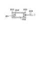
図1Aは、マス運動アクチュエータとして働く小さなd.c.電気モータ(100)のシャフト(102)に、偏心マス(101)を取り付けることにより得られる振動触覚ユニットの一実施例を示している。ここで、該マスはパイの形状を有しているが、重心を回転軸から外して偏心性を与える他の如何なる形状を用いてもよい。この偏心性は、回転の間に向きが変わる力ベクトルを生じさせて、ユニットに振動を誘起する。このマスは、例えば、鋼、アルミニウム、プラスチックまたは容器に収容された液体のような如何なる材料でできていてもよい。 FIG. 1A shows one embodiment of a vibrotactile unit obtained by attaching an eccentric mass (101) to the shaft (102) of a small d.c. electric motor (100) that acts as a mass motion actuator. Here, the mass has a pie shape, but any other shape that gives eccentricity by removing the center of gravity from the rotation axis may be used. This eccentricity creates a force vector that changes direction during rotation and induces vibrations in the unit. The mass may be made of any material such as, for example, steel, aluminum, plastic or a liquid contained in a container.
図1Bは、線形マス運動アクチュエータ(105)のシャフト(105)にマス(103)を取り付けることにより得られる、振動触覚ユニットの他の実施例を示している。該マスはここではディスク状であるが、他の如何なる形状を用いてもよい。この線形アクチュエータは、該マスを前後に移動させ、これを急激に加速または減速することによって、当該ユニットに振動を誘起させる。当該マスは、例えば、鋼、アルミニウム、プラスチックまたは容器に収容した流体のような如何なる材料でできていてもよい。 FIG. 1B shows another embodiment of the vibrotactile unit obtained by attaching the mass (103) to the shaft (105) of the linear mass motion actuator (105). The mass is disc-shaped here, but any other shape may be used. The linear actuator moves the mass back and forth and rapidly accelerates or decelerates it to induce vibration in the unit. The mass may be made of any material such as, for example, steel, aluminum, plastic or a fluid contained in a container.
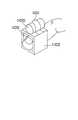
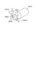
図2Aおよび図2Bは、それぞれ、ケースの中にマス運動アクチュエータ(202)およびマス(201)を収容した一例を示す断面図および斜視図である。ここでも、偏心マス(201)は電気モータのシャフト(204)に取り付けられている。ケースは、運動するマスが使用者によって破壊されるのを防止し、また使用者が該マスに打撃されるのを防止する。このケーシングは剛性の如何なる材料で作製してもよく、アルミニウム、鋼、プラスチック、ガラス、ガラス繊維複合体等のような種々の材料で作製することができる。典型的には、当該装置ができるだけ限り邪魔にならないように、小さく且つ軽量のマス運動アクチュエータ、マス、収容手段および固定手段を有するのが望ましい。本発明のこの実施例は、以下、後続の多くの図面で用いられる振動触覚ユニットのサンプルとしての役割を有することになる。 2A and 2B are a cross-sectional view and a perspective view, respectively, showing an example in which the mass motion actuator (202) and the mass (201) are housed in a case. Again, the eccentric mass (201) is attached to the shaft (204) of the electric motor. The case prevents the moving mass from being destroyed by the user and prevents the user from being hit by the mass. The casing may be made of any rigid material and can be made of various materials such as aluminum, steel, plastic, glass, glass fiber composites, and the like. Typically, it is desirable to have a small and lightweight mass motion actuator, mass, containment means and securing means so that the device is as unobtrusive as possible. This embodiment of the invention will serve as a sample of the vibrotactile unit used in many subsequent figures.
図3は、指先に振動触覚ユニットを取り付けるための一つの固定手段を示している。この例では、振動触覚ユニット(300)が、固定手段(301)を用いて指先の手掌側に直接取り付けられている。この固定手段は、例えば布、ファブリック、テープ、べルクロR(登録商標)または軟質ポリマーのような可撓性材料で作製してもよく、或いは金属、硬質ポリマーまたは木のような剛性材料で作製してもよい。固定手段は指全体を取り囲む必要はなく、クランピングまたはピンチングによって指に把持させればよく、或いはそれを粘着剤またはテープで貼り付けてもよい。また、使用者が手袋を着用するときには、振動触覚ユニットをこの手袋に縫い付け、または結合してもよく、手に直接固定する必要はない。これは、人間の身体に振動触覚ユニットを配置する種々の方法を示した以下の図においても同様である。FIG. 3 shows one fixing means for attaching the vibrotactile unit to the fingertip. In this example, the vibrotactile unit (300) is directly attached to the palm side of the fingertip using the fixing means (301). The fixing means is produced, for example cloth, fabric, tape, base RukuroR may be made of a flexible material, such as(R) or the soft polymer, or a metal, a rigid material such as hard polymer or wood May be. The fixing means does not need to surround the entire finger, and may be held by the finger by clamping or pinching, or may be affixed with an adhesive or tape. Also, when the user wears a glove, the vibrotactile unit may be sewn or coupled to the glove and need not be secured directly to the hand. The same applies to the following figures showing various methods of arranging the vibrotactile unit on the human body.
図4は、振動触覚ユニット(400)を、固定手段(401)を用いて指に装着する別の方法を示している。この場合、当該ユニットは、特有の触感または振動刺激を与えるために、指先の背面側の指爪(検知する身体部分)の上に直接配置される。このユニットは爪、その下の肉および骨を十分な振幅で振動させるので、その感覚は、皮膚で局部的に感じられるのではなく、指全体で感じることができる。 FIG. 4 shows another method of attaching the vibrotactile unit (400) to the finger using the fixing means (401). In this case, the unit is directly placed on the fingernail (the body part to be detected) on the back side of the fingertip in order to give a specific tactile sensation or vibration stimulus. This unit vibrates the nails, the underlying flesh and bones with sufficient amplitude so that the sensation can be felt not only locally on the skin but also on the entire finger.
図5は、振動触覚ユニット(500)を、固定手段(501)を用いて指に装着する別の方法を示している。この場合、当該ユニットは基節骨の背面に配置される。該ユニットは指全体に感覚を与えるから、それが背面に装着されていても、手掌で仮想物体に接触したときには当該部分に感覚が与えられるであろう。掌側での物理的物体の操作と組み合わせて用いると、掌側での振動感覚は高められる。これらの特徴は、基節骨に限定されない。何れの指骨または部分の背面に装着した場合にも同じ効果を生じるであろう。 FIG. 5 shows another method of attaching the vibrotactile unit (500) to the finger using the fixing means (501). In this case, the unit is placed on the back side of the proximal phalanx. Since the unit gives a sensation to the entire finger, even if it is worn on the back, the part will be given a sensation when it touches the virtual object with the palm. When used in combination with the manipulation of a physical object on the palm side, the vibration sensation on the palm side is enhanced. These features are not limited to the proximal phalanx. The same effect will occur when worn on the back of any phalange or part.
図6は、振動触覚ユニット(600)を、固定手段(601)を用いて指に装着する別の方法を示している。この場合、当該ユニットは使用者の手掌に配置される。手袋(器具を備え、または備えていない)を着用するときは、当該ユニットを手袋の内側または外側のポケット状キャビティー内に装着してもよく、明確に手に固定する必要はない。 FIG. 6 shows another method of attaching the vibrotactile unit (600) to the finger using the fixing means (601). In this case, the unit is placed in the palm of the user. When wearing gloves (with or without equipment), the unit may be worn in a pocket-like cavity inside or outside the glove, and does not need to be clearly secured to the hand.
図7は、固定手段(701)を用いて、振動触覚ユニット(700)を使用者に装着する別の方法を示している。この場合、当該ユニットは中手骨の背面または手の裏に配置される。ここでも、手袋(器具を備え、または備えていない)を着用するときは、当該ユニットを手袋の内側または外側のポケット状キャビティー内に装着してもよく、明確に手に固定する必要はない。 FIG. 7 shows another method of attaching the vibrotactile unit (700) to the user using the fixing means (701). In this case, the unit is placed on the back of the metacarpal bone or on the back of the hand. Again, when wearing gloves (with or without equipment), the unit may be placed in a pocket-like cavity inside or outside the glove and does not need to be clearly fixed to the hand .
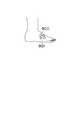
図8は、固定手段(801)を用いて、振動触覚ユニット(800)を使用者に装着する別の方法を示している。この場合、当該ユニットは使用者の足の頂部に配置される。ソックス状の下着(器具を備え、または備えていない)を着用するときは、当該ユニットをこの下着の内側または外側のポケット状キャビティー内に装着してもよく、明確に足に固定する必要はない。 FIG. 8 shows another method of attaching the vibrotactile unit (800) to the user using the fixing means (801). In this case, the unit is placed on the top of the user's foot. When wearing a sock-like undergarment (with or without equipment), the unit may be placed in a pocket-like cavity inside or outside the undergarment and need to be clearly fixed to the foot Absent.
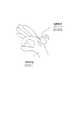
図9は、振動触覚ユニット(900)を使用者に装着する別の方法を示している。この例では、当該ユニットが使用者の頭部に配置される。帽子状の下着(器具を備え、または備えていない)を着用するときは、当該ユニットをこの下着の内側または外側のポケット状キャビティー内に装着してもよく、明確に頭部に固定する必要はない。配置する位置には、側頭部(900)、前頭部(901)、頭頂部(902)、後頭部(903)が含まれるが、これらに限定されない。 FIG. 9 shows another method of attaching the vibrotactile unit (900) to the user. In this example, the unit is placed on the user's head. When wearing a hat-like undergarment (with or without equipment), the unit may be placed in a pocket-like cavity inside or outside the undergarment and must be clearly fixed to the head There is no. Arrangement positions include, but are not limited to, the temporal region (900), the frontal region (901), the crown (902), and the occipital region (903).
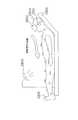
図10Aは、振動触覚ユニット(1000〜1012)を使用者に固定する別の方法を示している。これらの例において、当該ユニットは使用者の身体の正面または背面の全体に亘って配置される。ボディースーツ(器具を備え、または備えていない)を着用するときは、当該ユニットをこのスーツの内側または外側のポケット状キャビティー内に装着してもよく、明確に身体に固定する必要はない。アクチュエータの組み合わせを駆動することにより、局部的な触感を制御することができる。例えば、前腕部(1007)および上腕部(1005)のアクチュエータが等しい強度で駆動すれば、使用者は、この二つの間に生じた一つの感覚源が存在するとの感覚をもつであろう。これは、身体の何れの位置にある振動ユニットの如何なる組合せについても適用され得る。この影響はまた、多くの振動触覚ユニットが連続的に活性化されたときにも明らかである。一つの振動が、駆動している振動触覚ユニットの間を「移動する」という感覚が存在する。図示の振動触覚ユニットは、当該ユニットを取り付ける種々の位置の例を示している。これらの位置の幾つかには、前頭部(1000)、肩(1001)、腕の側部(1003)、上腕部(1005)、胸部(1002)、乳頭部(1004)、腹部(1006)、前腕部(1007)、鼠蹊部(1008)、ヒップ(1009)、大腿部(1010)、膝部(1011)、および頸部(1012)が含まれるが、これらに限定されるものではない。 FIG. 10A shows another method of securing the vibrotactile unit (1000 to 1012) to the user. In these examples, the unit is placed over the entire front or back of the user's body. When wearing a bodysuit (with or without equipment), the unit may be mounted in a pocket-like cavity inside or outside the suit, and does not need to be specifically fixed to the body. By driving the combination of actuators, the local tactile sensation can be controlled. For example, if the forearm (1007) and upper arm (1005) actuators are driven with equal strength, the user will have the sensation that there is a single sensory source between the two. This can be applied to any combination of vibration units at any position on the body. This effect is also evident when many vibrotactile units are activated continuously. There is a sense that one vibration “moves” between the driving vibrotactile units. The illustrated vibrotactile unit shows examples of various positions where the unit is attached. Some of these positions include the forehead (1000), shoulder (1001), arm side (1003), upper arm (1005), chest (1002), papilla (1004), abdomen (1006) , Forearm (1007), buttocks (1008), hip (1009), thigh (1010), knee (1011), and neck (1012), including but not limited to .
図10Bは、振動触覚ユニット(1020〜1028)を使用者に固定する別の方法を示している。これらの例において、振動触覚ユニットは、使用者の身体の背面全体に亘って配置される。ボディースーツ(器具を備え、または備えていない)を着用するときは、当該ユニットをこのスーツの内側または外側のポケット状キャビティー内に装着してもよく、明確に身体に固定する必要はない。図示の振動触覚ユニットは、当該ユニットを取り付ける種々の候補位置の例を示している。これらの位置の幾つかには、後頭部(1020)、首の背面(1021)、肩胛骨の間(1022)、上腕部の裏面(1023)、前腕部の裏面(1025)、背中の下部(1024)、臀部(1026)、大腿部の裏面(1027)、および脹ら脛(101028)が含まれるが、これらに限定されない。図10Bにおける振動触覚ユニットは、図10Aにおけるユニットと組み合わせてもよい。この複数の振動触覚ユニットは、多くの振動触覚ユニットで複雑な触感を発生させ得る一つの方法を示している。 FIG. 10B shows another method of securing the vibrotactile unit (1020 to 1028) to the user. In these examples, the vibrotactile unit is placed across the back of the user's body. When wearing a bodysuit (with or without equipment), the unit may be mounted in a pocket-like cavity inside or outside the suit, and does not need to be specifically fixed to the body. The illustrated vibrotactile unit shows examples of various candidate positions to which the unit is attached. Some of these positions include the back of the head (1020), the back of the neck (1021), between the shoulder ribs (1022), the back of the upper arm (1023), the back of the forearm (1025), the lower back (1024) , Buttocks (1026), thigh back (1027), and calves (101028). The vibrotactile unit in FIG. 10B may be combined with the unit in FIG. 10A. This plurality of vibrotactile units represents one way in which many vibrotactile units can generate complex tactile sensations.
図11Aおよび図11Bは、指の操作を邪魔することなく、指先が刺激され得るように装着された振動触覚ユニットを示している。図11Aは、本発明の斜視図であり、図11Bはその正面図である。その端部が開いていても閉じていてもよい構造体(1002)が、指先を取り囲んでいる。固定手段は三つのパーツ、即ち、指先を当該構造体に固定するパーツ1、振動触覚ユニットを当該構造体に固定するパーツ2、および当該構造体(1102)であるパーツ3を具備している。固定手段(1103)であるパーツ1(これは可撓性部材でも剛性部材でもよい)は、指先の掌側で指を構造体に保持する。このパーツは調節可能であっても、固定であっても、可撓性であっても、または伸長可能であってもよい。パーツ2において、振動触覚ユニット(1100)は、可撓性部材でも剛性部材でもよい手段(1101)を用いて、指の手掌側から離れた構造体の頂部に装着される。この方法において、振動触覚ユニットからの振動は、構造体を介して指の手掌側に直接伝達されて、該手掌側の局部的な神経により大きな刺激を与える。もう一つの実施例では、構造体(1102)および振動触覚ユニットケーシング(1100)を一つのパーツで作製して、固定手段(1101)であるパーツ2を不要にすることができる。 FIG. 11A and FIG. 11B show the vibrotactile unit worn so that the fingertip can be stimulated without disturbing the operation of the finger. FIG. 11A is a perspective view of the present invention, and FIG. 11B is a front view thereof. Surrounding the fingertip is a structure (1002) that may be open or closed at its ends. The fixing means includes three parts, namely, a
図12Aおよび図12Bは、指の操作が当該ユニットに邪魔されることなく、指が剌激され得るように装着された振動触覚ユニットを示している。図12Aは、本発明の斜視図を示しており、図12Bはその側面図を示している。構造体(1202)は、指先の手掌側に取り付けられる。固定手段は三つのパーツ、即ち、指を当該構造体に固定するパーツ1、振動触覚ユニットを当該構造体に固定するパーツ2、および当該構造体(1202)であるパーツ3を具備している。パーツ1(1203)は可撓性部材でも剛性部材でもよい。このパーツは調節可能であっても、固定であっても、可撓性であっても、または伸長可能であってもよい。パーツ2において、振動触覚ユニット(1200)は、可撓性部材でも剛性部材でもよい手段(1201)を用いて、指の手掌側から離れた構造体の頂部に装着される。他の実施例では、構造体(1202)および振動触覚ユニットケーシング(1200)を一つのパーツで作製して、固定手段(1201)であるパーツ2を不要にすることができる。 FIG. 12A and FIG. 12B show the vibrotactile unit mounted so that the finger can be stimulated without being disturbed by the operation of the finger. FIG. 12A shows a perspective view of the present invention, and FIG. 12B shows a side view thereof. The structure (1202) is attached to the palm of the fingertip. The fixing means includes three parts, namely, a
図13は、マス運動アクチュエータ/マスアセンブリーのためのケーシングを必要としない振動触覚ユニットおよび固定手段を示している。小さな剛性または半剛性の構造体(1302)は、偏心マス(1301)がマス運動モータ(1300)のシャフト(1304)の主軸回りで回転するのを指が妨害できないように、振動触覚ユニットを指先の上方に持ち上げている。構造体(1302)は、剛性でも可撓性でもよく且つ当該構造体と一体でも別体でもよいストラップ(1303)を用いて指先に取り付けられる。 FIG. 13 shows a vibrotactile unit and securing means that do not require a casing for the mass motion actuator / mass assembly. A small rigid or semi-rigid structure (1302) moves the vibrotactile unit to the fingertip so that the finger cannot block the eccentric mass (1301) from rotating around the main shaft of the shaft (1304) of the mass motor (1300). Is lifted above. The structure (1302) is attached to the fingertip using a strap (1303) that may be rigid or flexible and may be integral with or separate from the structure.
図14は、マス運動アクチュエータ/マスアセンブリーのためのケーシングを必要としない振動触覚ユニットおよび固定手段を示している。小さな剛性または半剛性の構造体(1404)は、偏心マス(1402)がマス運動モータ(1401)のシャフト(1403)の主軸回りで回転するのを指が妨害できないように、振動触覚ユニットを中央ファランクスの上方に持ち上げている。構造体(1404)は、剛性でも可撓性でもよく且つ当該構造体と一体でも別体でもよいストラップ(1405)を用いて中央ファランクスに取り付けられる。 FIG. 14 shows a vibrotactile unit and securing means that do not require a casing for the mass motion actuator / mass assembly. A small rigid or semi-rigid structure (1404) centers the vibrotactile unit so that the finger cannot block the eccentric mass (1402) from rotating around the main shaft of the mass motion motor (1401) shaft (1403). Lifts above the phalanx. The structure (1404) is attached to the central phalanx using a strap (1405) that may be rigid or flexible and may be integral or separate from the structure.
図15は、振動触覚ユニットが、感得される振動の振幅および周波数を変化させるためにバネ(1501)を介して指先に接続されるような、更に別の振動触覚ユニット(1500)および固定手段を示している。可撓性部材でも剛性部材でもよいストラップ(1502)は、バネを指先に保持する。このバネは、振動触覚ユニットの本来の周波数を変化させる。或いは、この振動触覚ユニット/バネ装置は、指の上ではなく指の下に取り付けることもできる。また、このバネを或る種のアクチュエータで置き換えて、振幅および周波数を制御し、および/または振幅および周波数の範囲を広げてもよい。加えて、バネまたはアクチュエータと組み合わせてダンパーを導入して、感知される振動の振幅および周波数を更に制御および/または拡大してもよい。このダンパーの中に電気的/流体学的な液体を使用して、当該機械的システムにおける制動時間を制御してもよい。 FIG. 15 shows yet another vibrotactile unit (1500) and securing means such that the vibrotactile unit is connected to the fingertip via a spring (1501) to change the amplitude and frequency of the sensed vibration. Is shown. A strap (1502), which may be a flexible member or a rigid member, holds the spring on the fingertip. This spring changes the natural frequency of the vibrotactile unit. Alternatively, the vibrotactile unit / spring device can be attached under the finger rather than over the finger. The spring may also be replaced with some type of actuator to control amplitude and frequency and / or widen the range of amplitude and frequency. In addition, dampers may be introduced in combination with springs or actuators to further control and / or expand the sensed vibration amplitude and frequency. An electrical / rheological liquid may be used in the damper to control the braking time in the mechanical system.
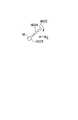
図16A,16B,16Cおよび図16Dは、偏心マスをシャフトに装着する方法の変形例を示している。偏心マスの旋回半径Kは、シャフトの角速度が増大するに伴って増大する。上方の三つの図(図16A,16Bおよび16C)はその原理を示しており(w2>w1>0)、一番下の斜視図(図16D)は実施器具を提供する。図16Dにおいて、構造体(1601)はマス運動アクチュエータ(1600)のシャフト(1602)に取り付けられている。該構造体は、バネ(1604)およびマス(1603)のアセンブリーを具備している。該バネの一端は当該構造体の内側に取り付けられ、また他端はマスに取り付けられている。当該マスは、構造体中のガイドの内側を、シャフトに向って前後に自由に移動する。旋回半径Kは、当該マス(1603)の旋回中心とマス運動アクチュエータシャフト(1602)の主軸との間の距離である。シャフトの角速度が増大するに伴って、当該マスにより感じられる遠心力は増大し、バネを更に伸ばして旋回半径を増大させる。この装置は、高角速度においてより大きな振動を得ることができるように、始動時における装置の初期角度を最小限にして、当該マスの偏心を徐々に増大させる。これによって、シャフトに保持されているベアリングに対するストレスが緩和され、且つ回転を開始させるのに必要な大きな初期トルク(回転を維持するのに必要なトルクに比較して)が低減される。或いは、この受動的なバネを、当該マスの旋回半径を制御または設定する能動的な装置で置き換えてもよい。この能動装置は、形状記憶合金アクチュエータ、または当該マスの位置を制御できる他の何れかの機構を具備することができる。 16A, 16B, 16C and FIG. 16D show a modification of the method of attaching the eccentric mass to the shaft. The turning radius K of the eccentric mass increases as the angular velocity of the shaft increases. The upper three views (FIGS. 16A, 16B and 16C) illustrate the principle (w2> w1> 0), and the bottom perspective view (FIG. 16D) provides the implement. In FIG. 16D, the structure (1601) is attached to the shaft (1602) of the mass motion actuator (1600). The structure comprises a spring (1604) and mass (1603) assembly. One end of the spring is attached to the inside of the structure, and the other end is attached to the mass. The mass is free to move back and forth inside the guide in the structure toward the shaft. The turning radius K is the distance between the turning center of the mass (1603) and the main axis of the mass motion actuator shaft (1602). As the angular velocity of the shaft increases, the centrifugal force felt by the mass increases, further extending the spring and increasing the turning radius. The device gradually increases the mass eccentricity, minimizing the initial angle of the device at start-up so that greater vibrations can be obtained at high angular velocities. This relieves stress on the bearing held on the shaft and reduces the large initial torque (compared to the torque required to maintain rotation) required to initiate rotation. Alternatively, this passive spring may be replaced with an active device that controls or sets the turning radius of the mass. The active device can comprise a shape memory alloy actuator or any other mechanism that can control the position of the mass.
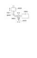
図17は、本発明の好ましい実施例において、電気的および機械的信号が触覚フィードバック制御システムを介して伝達される仕方を示している。図示の実施例では、振動触覚ユニットのマス運動アクチュエータとして、d.c.サーボモータ(1701)を用いている。コンピュータ(1707)または他の信号処理手段が、所望の駆動レベルの制御信号に対応したデジタル値を、デジタル/アナログ変換器D/A(1703)に送信する。次いで、該D/Aのアナログ出力は可変利得増幅器(1704)によって増幅されて、アナログ電圧駆動信号を生じる。この電圧はサーボモータに印加されて、所望の角速度でモータを駆動させる。該電圧信号は、所望のトルクで該モータを駆動させるために、交互に電流駆動信号に変換される。サーボ制御ループの速度減速は、タコメータフィードバック(図示せず)によって行えばよい。コンピュータ(1707)、デジタル/アナログ変換器(1703)、アナログ/デジタル変換器、A/D、(1702)、バス(1702)および可変利得増幅器(1704)は、信号処理装置の素子であってもよい。アナログ関節角度センサ(1705)に由来するA/D(1702)からのデジタル化された値は、物理状態信号として指の位置情報(測定された身体部分)をコンピュータに与える。仮想環境の応用において、物理状態信号は仮想の手に対応した動作を生じることができる。仮想の手の一つの指が仮想物体と交差することが分かったら、コンピュータは、仮想物体の形状および従順性の知識を用いて、仮想指に適用すべき仮想の力を計算する。次いで、コンピュータは使用者の指(検知する身体部分)に装着された振動触覚ユニットに駆動信号を送り、仮想の力に関する触覚情報を伝達する。歪みゲージ、光ファイバー、電位計または他の角度センサを、アナログ関節角度センサ(1705)として使用することができる。歪みゲージ角度センサは、クラマー等(Krameret al.)の米国特許第5、047、952号および第5,280,265号に開示されており、これらの特許は本願明細書の一部をなす参照文献として本願に組み込まれる。 FIG. 17 illustrates how electrical and mechanical signals are transmitted via a haptic feedback control system in a preferred embodiment of the present invention. In the illustrated embodiment, a d.c. servo motor (1701) is used as the mass motion actuator of the vibrotactile unit. A computer (1707) or other signal processing means transmits a digital value corresponding to a control signal of a desired drive level to a digital / analog converter D / A (1703). The analog output of the D / A is then amplified by a variable gain amplifier (1704) to produce an analog voltage drive signal. This voltage is applied to the servo motor to drive the motor at a desired angular velocity. The voltage signal is alternately converted into a current drive signal in order to drive the motor with a desired torque. The speed reduction of the servo control loop may be performed by tachometer feedback (not shown). The computer (1707), the digital / analog converter (1703), the analog / digital converter, the A / D, (1702), the bus (1702), and the variable gain amplifier (1704) may be elements of the signal processing device. Good. The digitized value from the A / D (1702) derived from the analog joint angle sensor (1705) provides finger position information (measured body part) to the computer as a physical state signal. In a virtual environment application, a physical state signal can cause an action corresponding to a virtual hand. Once it is found that one finger of the virtual hand intersects the virtual object, the computer uses the knowledge of the virtual object's shape and compliance to calculate the virtual force to be applied to the virtual finger. Next, the computer sends a drive signal to the vibrotactile unit attached to the user's finger (the body part to be detected) to transmit tactile information related to the virtual force. A strain gauge, optical fiber, electrometer or other angle sensor can be used as the analog joint angle sensor (1705). Strain gauge angle sensors are disclosed in Kramer et al. U.S. Pat. Nos. 5,047,952 and 5,280,265, which are incorporated herein by reference as part of the present specification. Incorporated.
図18Aおよび図18Bは、本発明の好ましい実施例を示している。アメリカ合衆国カリホルニア州パロアルト所在のバーチャルテクノロジー社によって製造されたサイバーグラブTM(登録商標)のような機器を備えた手袋(1820)は、その上に、手(測定される身体部分)の関節角度を測定するセンサ類(1807〜1819)を有している。同図において、使用者が手袋を使用していても物理的物体を手で扱えるように、手袋の指先は開放されている。これによって、使用者は現実の物体の触感を感じることが可能になる。振動触覚ユニット(1801〜1806)は円筒状のハウジング内に収容されて、夫々の指(1801〜1804)、親指(1805)および手掌(1806)に固定されている。ケーシングは円筒状プラスチックでできており、マスの運動を使用者から保護し、且つ使用者を回転するマスから保護する。18A and 18B show a preferred embodiment of the present invention. Gloves (1820) equipped with equipment such as CybergrabTM (registered trademark) manufactured by Virtual Technology, Inc., located in Palo Alto, California, United States, measure joint angles of hands (measured body parts) Sensors (1807 to 1819). In the figure, the fingertip of the glove is opened so that the user can handle the physical object even when the glove is used. As a result, the user can feel the touch of an actual object. The vibrotactile units (1801 to 1806) are housed in a cylindrical housing and are fixed to the respective fingers (1801 to 1804), thumb (1805) and palm (1806). The casing is made of cylindrical plastic and protects the mass movement from the user and protects the user from the rotating mass.
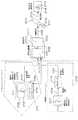
図19Aは、手の形態、並びに手の空間的配置を測定できる検知手袋(1900)を着用した使用者を示している。この検知手袋は、手の指および甲に固定された振動触覚ユニット(1901)を有している。使用者は、コンピュータモニター(1904)上の彼の手の画像表示を通して、視覚的フィードバックを受け取る。コンピュータ(1904)は、手袋に装着されたセンサから、手袋センサインターフェース(1902)を介して状態信号(使用者の手の空間的配置に関する情報)を受け取る。視覚画像の手(1906)がモニター上の仮想物体(1905)に接触(1908)すると、コンピュータは制御信号を振動触覚ユニットドライバ(1903)に送信し、次いで該ドライバは駆動信号を振動触覚ユニット(1901)に送信する。 FIG. 19A shows a user wearing a sensing glove (1900) that can measure hand morphology as well as the spatial arrangement of the hand. This detection glove has a vibrotactile unit (1901) fixed to the fingers and back of the hand. The user receives visual feedback through an image display of his hand on the computer monitor (1904). The computer (1904) receives a status signal (information on the spatial arrangement of the user's hand) from a sensor attached to the glove via the glove sensor interface (1902). When the hand (1906) of the visual image contacts (1908) the virtual object (1905) on the monitor, the computer sends a control signal to the vibrotactile unit driver (1903), which then sends the drive signal to the vibrotactile unit (1903). 1901).
同様の設定において、図19Bは同じ手袋(1900)と、画像ディスプレイの代わりに、ロボット腕(1911)を遠隔制御するコンピュータインターフェースと、を示している。ロボットはその把持器上に、ロボットが物理的物体(1913)に触れた時点を検出する接触センサを有している。使用者は、指(測定される身体部分)の位置読み取りを生じる手袋上のセンサを介してロボット腕を制御するが、その際、この位置の読みは手袋インターフェース装置(1902)に送信され、次いでコンピュータ(1904)に出力され、更にコンピュータは適切な命令をロボットに送信する。ロボットの位置情報および接触情報(1910)は、次いで状態信号としてコンピュータにフィードバックされる。コンピュータはこの信号および装置を解釈し、如何なる種類の振動フィードバックを、振動触覚ユニットドライバ(1903)を介して使用者の振動触覚ユニット(1901)(他の振動触覚ユニットは図示せず)に送信すべきかを決定する。力または圧力センサを、接触センサの代わりに把持器に装着してもよい。次いで、使用者は、物体に対する力または圧力に応じた変化するレベルの振動フィードバックを受け取る。これによって、特に一定の把持力で破壊されるような繊細な物体の取扱いにおいて、より正確且つ安全に仕事を行うための遠隔操作が可能になる。使用者は、接触フィードバックを使用するために、必ずしもロボットまたは接触対象を制御する必要はない。振動触覚装置は、単純に動作して、使用者の動作の結果としての物体との接触の有無を使用者に知らせることができる。 In a similar setting, FIG. 19B shows the same glove (1900) and a computer interface that remotely controls the robot arm (1911) instead of an image display. The robot has, on its gripper, a contact sensor that detects when the robot touches the physical object (1913). The user controls the robot arm via a sensor on the glove that produces a position reading of the finger (the body part to be measured), where the position reading is sent to the glove interface device (1902), and then The data is output to the computer (1904), and the computer transmits an appropriate command to the robot. The robot position information and contact information (1910) are then fed back to the computer as status signals. The computer should interpret this signal and device and send any type of vibration feedback to the user's vibrotactile unit (1901) (other vibrotactile units not shown) via the vibrotactile unit driver (1903). Decide what to do. A force or pressure sensor may be attached to the gripper instead of the contact sensor. The user then receives a varying level of vibration feedback depending on the force or pressure on the object. This makes it possible to perform a remote operation for performing work more accurately and safely, especially when handling a delicate object that is broken with a constant gripping force. The user does not necessarily have to control the robot or the contact object in order to use contact feedback. The vibrotactile device can simply operate to inform the user of contact with an object as a result of the user's movement.
図20は、測定される身体部分(2003)は足であるが、振動触覚ユニット(2001)は検知する身体部分(2004)として動作する指に装着されるような、バーチャルリアリティーにおける実施例を示している。この足は、コンピュータシミュレーションにおける画像(2004)と関連づけられている。この場合、画像は足のように見える。足の動きは、身体センサインターフェース(2006)を介してコンピュータ(2008)に送信され、またコンピュータモニターに映し出される。画像の足(2004)が仮想物体(2010)と接触したことをコンピュータ(2008)が決定したとき、コンピュータはこの状態信号を解釈して、制御信号を振動触覚ユニットドライバー(2007)に送信し、指の上の振動触覚ユニット(2001)を駆動させる。これは、画像の足が仮想物体に接触(2005)するように使用者が彼の足を動かすこと、または仮想物体が使用者の動作とは関係なく画像の足の中へ移動することに起因して起こり得る。使用者は次に、仮想物体の接触と指先の感覚とを関連付ける必要がある。これは足が接触するときに足を振動させるように自然なようには思えないが、これは測定される身体部分から分離された検知する身体部分を例示している。これは、測定される身体部分を検知する身体部分と一致させることができないとき、例えば、測定される身体部分が眼球であったり、または測定される身体部分が別の使用者のものであるときに必要とされる。 FIG. 20 shows an example in virtual reality where the body part to be measured (2003) is a foot, but the vibrotactile unit (2001) is worn on a finger acting as a body part to detect (2004). ing. This foot is associated with an image in computer simulation (2004). In this case, the image looks like a foot. The movement of the foot is transmitted to the computer (2008) via the body sensor interface (2006) and is displayed on the computer monitor. When the computer (2008) determines that the foot of the image (2004) has contacted the virtual object (2010), the computer interprets this status signal and sends a control signal to the vibrotactile unit driver (2007), Drive the vibrotactile unit (2001) on the finger. This is because the user moves his foot so that the foot of the image touches the virtual object (2005), or the virtual object moves into the foot of the image regardless of the user's motion. Can happen. The user then needs to associate the contact of the virtual object with the fingertip sensation. While this does not seem natural to cause the foot to vibrate when the foot contacts, this illustrates the sensing body part separated from the body part being measured. This is when the measured body part cannot be matched with the sensing body part, for example when the measured body part is an eyeball or the measured body part is from another user Is needed to.
図21Aおよび図21Bは、位置センサおよび振動触覚ユニット(2100)の両方を含んだ手袋(2101)を示している。バーチャルテクノロジー社のサイバーグラブTM(登録商標)は、適切な位置センサを備えた手袋の一例である。これらのセンサ類は、手および指の空間的配置を測定する。コンピュータはジエスチャー認識ソフトウエアを用いて、所定の手の形態または運動がジェスチャーで表されたかどうかを決定する。図21Aにおいて、振動触覚ユニットは、特定の静的姿勢が検出されたことを使用者に信号で知らせる。認識された運動する手または腕のダイナミックな運動を含むジェスチャーに応答して、異なった振動触覚感覚を発生させることができる(図21B)。これは、認識すべきジェスチャーのために、ジェスチャー認識ソフトウエアをトレーニングする上でも有用であろう。人間は正確にジェスチャーを繰り返すことができないから、ソフトウエアのトレーニングに際し、使用者は、同じジェスチャーを反復して行って、ある種の平均位置を得なければならない。振動触覚フィードバックを用いれば、使用者のジェスチャーを認識するように認識ソフトウエアをトレーニングすると同時に、使用者は、彼のジェスチャーを更に良好に反復するように訓練され得る。ジェスチャーをより良好に反復することによって、所定の手のジェスチャーについてのセンサ読み取り値の統計的分布は減少し、これにより認識システムの特性を改善することができる。21A and 21B show a glove (2101) that includes both a position sensor and a vibrotactile unit (2100). Virtual Technology's Cybergrab™ is an example of a glove with a suitable position sensor. These sensors measure the spatial arrangement of hands and fingers. The computer uses gesture recognition software to determine whether a given hand form or movement is represented by a gesture. In FIG. 21A, the vibrotactile unit signals the user that a specific static posture has been detected. Different vibrotactile sensations can be generated in response to recognized gestures involving dynamic movement of the moving hand or arm (FIG. 21B). This may also be useful in training gesture recognition software for gestures to be recognized. Since humans cannot repeat gestures accurately, when training software, the user must repeat the same gestures to obtain a certain average position. With vibrotactile feedback, the user can be trained to repeat his gestures better, while at the same time training the recognition software to recognize the user's gestures. By better repeating the gesture, the statistical distribution of sensor readings for a given hand gesture is reduced, which can improve the characteristics of the recognition system.
図22は、音楽的応用における振動触覚ユニットを示している。これらのユニットは、使用者のボディースーツまたは着衣上に直接装着される。振動触覚ユニットのグループ分け(2211)を含む身体上の異なった領域(2200〜2210)は、オーケストラにおける異なった楽器に対応することができ、また音楽的経験を高めるように働くことができる。例えば、チェロによって生み出される音楽は、身体領域に位置する振動触覚ユニットを通して、使用者の大腿(2204)の上に比例した振動を与える。同様に、ドラムは胸部領域(2201)等を刺激するユニットに振動を誘起する。一つのタイプの楽器に対応した複数の振動触覚ユニットを含む身体の部分は、個々の楽器に対応した個々の振動触覚ユニットを有していてもよい。例えば、身体のチェロ部分は、上部大腿の第一席チェロと、下部大腿の第二席チェロとを有するように示されている。使用者は、楽器を「感じる」受動的聴取者であってもよく、或いは、振動感覚をフィードバックとして受け取ることにより、音楽の創作における能動的関与者であることもできる。 FIG. 22 shows a vibrotactile unit in musical applications. These units are mounted directly on the user's bodysuit or clothing. Different areas (2200-2210) on the body, including groupings of vibrotactile units (2211), can accommodate different instruments in the orchestra and can serve to enhance the musical experience. For example, the music produced by the cello provides proportional vibrations on the user's thigh (2204) through vibrotactile units located in the body area. Similarly, the drum induces vibrations in units that stimulate the chest region (2201) and the like. A body part including a plurality of vibrotactile units corresponding to one type of musical instrument may have individual vibrotactile units corresponding to individual musical instruments. For example, the cello part of the body is shown to have a first cello in the upper thigh and a second cello in the lower thigh. The user may be a passive listener who “feels” the instrument, or may be an active participant in the creation of music by receiving vibration sensations as feedback.
図23は、くつろぎへの応用を示している。この場合、振動触覚ユニットのアレイは水の流れまたは風邪をシミュレートする。この例において、使用者はコーチ(2301)に横になり、頭部に装着したディスプレイ(2302)を通して仮想ビーチシーンの中に没入し、ビーチに座る。使用者は頭部に装着したイヤホーン(2301)を通して海の音を聞き、ヒートランプ(2303)を通して日光の暖かさを感じる。次いで、振動触覚ユニットが連続的にパルス駆動されて感覚の「波」を創造するときに、使用者は、該ユニットによって刺激された風を感じる。例えば、頭部(2304)から出発して爪先(2305)で終わるように、振動触覚ユニットを交互にパルス駆動することによって、風は頭部から爪先へと流れることができる。同様に、使用者が仮想の水を通して泳ぐときに、パルス駆動の波(おそらく大きな振幅ではあるが)として水を感じる。このようにして、使用者はくつろぎまたは娯楽を得ることができる。 FIG. 23 shows an application for relaxation. In this case, the array of vibrotactile units simulates water flow or a cold. In this example, the user lies on the coach (2301), immerses in the virtual beach scene through the display (2302) worn on the head, and sits on the beach. The user hears the sound of the sea through the earphone (2301) attached to the head and feels the warmth of sunlight through the heat lamp (2303). Then, when the vibrotactile unit is continuously pulsed to create a “wave” of sensation, the user feels the wind stimulated by the unit. For example, wind can flow from the head to the toes by alternately pulsing the vibrotactile unit so that it starts at the head (2304) and ends at the toes (2305). Similarly, when a user swims through virtual water, they feel the water as a pulse-driven wave (possibly with a large amplitude). In this way, the user can get relaxation or entertainment.
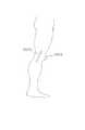
図24Aおよび図24Bは、例えば使用者が膝を負傷している場合の医療的応用を示している。振動触覚ユニット(2401)は、図24Aに示す理学療法の際に、膝に装着された曲げセンサ(2400)と組み合わせて用いられる。振動触覚ユニットユニットは、膝が適切に運動するときに使用者に通知し、膝が医者に処方された安全限界よりも更に曲がったときに使用者に警告して、図24Bに示すように修復を改善する。更に、他のセンサと組み合わせた振動触覚ユニットは、何等かの生体フィードバック適用において使用することができる。 FIGS. 24A and 24B illustrate medical applications where, for example, the user has a knee injury. The vibrotactile unit (2401) is used in combination with a bending sensor (2400) attached to the knee during the physical therapy shown in FIG. 24A. The vibrotactile unit unit notifies the user when the knee moves properly and warns the user when the knee bends further than the safety limits prescribed by the doctor, repairing as shown in FIG. 24B. To improve. Furthermore, vibrotactile units in combination with other sensors can be used in any biofeedback application.
図25A、25Bおよび図25Cは、偏心マスに基づく振動触覚ユニットにより発生した振動の、振幅および周波数成分をデカップリングするためのアプローチを示している。この実施例において、振動触覚ユニットは、ロータリー電気モータ(2501)と、偏心的に装着されたマス(2500)と、シャフト(2502)に装着されて該シャフトの角度位置を決定するセンサ(2503)と、閉ループ制御システムとを具備している。シャフトの単一回転を達成する何れかの他の制御法則も使用できる。一つの例が図25Aに示されている。グラフの縦軸は正規化された電流を表し、横軸は軸の回転をラジアンで表している。これは、以下の非線形制御法則に対応している。
I=1,(δ≧θ>π)
I=−1,(π≧θ≧2π−δ)
I=0,(−δ>θ>δ)FIGS. 25A, 25B and 25C show an approach for decoupling the amplitude and frequency components of vibrations generated by a vibrotactile unit based on an eccentric mass. In this embodiment, the vibrotactile unit comprises a rotary electric motor (2501), an eccentrically mounted mass (2500), and a sensor (2503) mounted on the shaft (2502) to determine the angular position of the shaft. And a closed loop control system. Any other control law that achieves a single rotation of the shaft can also be used. One example is shown in FIG. 25A. The vertical axis of the graph represents the normalized current, and the horizontal axis represents the rotation of the shaft in radians. This corresponds to the following nonlinear control law.
I = 1, (δ ≧ θ> π)
I = -1, (π ≧ θ ≧ 2π−δ)
I = 0, (−δ>θ> δ)
初期条件を、速度がゼロで、マスの回転位置θ(ラジアン)が小さい値δになるように設定すれば(図25B)、このようにしてモータに送られる電流Iは、マスが全回転の1/2だけ加速してθ+δ(図25C)まで行き、他の半回転については減速して、理想的な場合には−δと+δの間で停止するに至る(図25C)。−δおよび+δの実際の位置は、当該システムの制御ループのバンド幅および摩擦および減速に応じて変化させなければならないかもしれない。振動または衝撃の大きさは電流の振幅によって設定され、周波数は上記制御を所望の周波数で繰り返すことにより設定される。単純なフィードバック制御ループ(例えばPID)は、夫々のパルスの前に、初期条件が正しいことを保障する。これの詳細は当業者の常識である。 If the initial conditions are set so that the speed is zero and the mass rotation position θ (radian) is a small value δ (FIG. 25B), the current I sent to the motor in this way is It accelerates by 1/2 to θ + δ (FIG. 25C), decelerates for the other half rotation, and stops in the ideal case between −δ and + δ (FIG. 25C). The actual positions of -δ and + δ may have to be varied depending on the control loop bandwidth and friction and deceleration of the system. The magnitude of vibration or impact is set by the amplitude of the current, and the frequency is set by repeating the above control at a desired frequency. A simple feedback control loop (eg PID) ensures that the initial conditions are correct before each pulse. Details of this are common knowledge of those skilled in the art.
図26Aは、偏心を制御可能な振動触覚ユニットの斜視図であり、図26Bはその側面図である。スリップディスク(2602)のような構造体がシャフト(2601)に装着されていて、シャフトに沿って前後に自由に摺動する。このスリップディスクは、それを偏心マス(2604)に結合するリンク(2605)に取り付けられている。位置決め装置(2603)はシャフト上のスリップディスクの位置を制御し、これはマスの位置、従ってその偏心度に影響する。図26Cは、マスの偏心を制御するために使用できる別の伝達法である。図26Cにおいて、この伝達系は素子(2606)を具備しており、該素子は可撓性部材、またはその一端で偏心マス(2604)に結合され他端で摺動スリップディスク(2602)に結合された中空シャフト(2601)の内側の液体であり得る。ここでも、シャフトに沿ったディスクの位置を位置決め装置(2603)を用いて制御することは、マスの偏心に影響する。素子(2606)は液体でもよく、2604は中空容器でもよい。液体はスリップディスク(2602)、または他の圧力発生手段によって管(2601)に通されるから、容器(2604)は液体で満たされ、液体マスの中心の有効旋回半径を増大させる。どの手段によってであれ、旋回半径を増大させることにより、振動触覚ユニットの振動の振幅および周波数を独立に制御することが可能である。 FIG. 26A is a perspective view of a vibrotactile unit capable of controlling eccentricity, and FIG. 26B is a side view thereof. A structure such as a slip disk (2602) is attached to the shaft (2601), and freely slides back and forth along the shaft. The slip disk is attached to a link (2605) that couples it to an eccentric mass (2604). The positioning device (2603) controls the position of the slip disk on the shaft, which affects the position of the mass and hence its eccentricity. FIG. 26C is another transmission method that can be used to control mass eccentricity. In FIG. 26C, the transmission system includes an element (2606) that is a flexible member or one end coupled to an eccentric mass (2604) and the other end coupled to a sliding slip disk (2602). It may be a liquid inside the formed hollow shaft (2601). Again, controlling the position of the disk along the shaft using the positioning device (2603) affects the eccentricity of the mass. The element (2606) may be a liquid and 2604 may be a hollow container. Since the liquid is passed through the tube (2601) by a slip disk (2602) or other pressure generating means, the container (2604) is filled with liquid and increases the effective turning radius of the center of the liquid mass. By any means, it is possible to independently control the amplitude and frequency of vibration of the vibrotactile unit by increasing the turning radius.
図27は、一つの適用において使用されるときの、振動触覚装置を含む部品およびこれら部品間の機能的関係を示すブロック図を与えている。幾つかの部品は、一方向の矢印で相互に関連付けて示されているが、この矢印は情報の双方向性フローを与えるように双方向性であってもよい。ブロックの間に追加の矢印を加えて、部品間の通信を与えてもよい。適用は、使用者の身体部分に振動感覚を提供することを含むことができる。その場合、この振動感覚は仮想環境シミュレーション(バーチャルシミュレーション)および/または身体の物理的状態のシミュレーション(物理的シミュレーション)と関連しており、その身体は使用者の身体であっても他の人の身体でもよい。1以上のバーチャルシミュレーションは、1以上の物理的シミュレーションと共存してもよく、また更なるタイプのシミュレーションと組み合わせて振動感覚を発生させてもよい。 FIG. 27 provides a block diagram illustrating the components including the vibrotactile device and the functional relationship between these components when used in one application. Some parts are shown associated with each other by a unidirectional arrow, but the arrow may be bidirectional to provide a bidirectional flow of information. Additional arrows may be added between the blocks to provide communication between the parts. Application may include providing a vibration sensation to the user's body part. In this case, this vibration sensation is related to a virtual environment simulation (virtual simulation) and / or a physical physical state simulation (physical simulation). It may be the body. One or more virtual simulations may coexist with one or more physical simulations and may generate vibration sensations in combination with further types of simulations.
図27の例示的なバーチャルシミュレーション(2722)は、コンピュータモニター(2709)を備えたコンピュータ(2706)を具備している。バーチャルシミュレーションを行うために、コンピュータは典型的に、コンピュータシミュレーション(2705)(典型的にはコンピュータソフトウエアプログラムの形態である)を発生し、処理し、実行またはランさせる。この例示的バーチャルシミュレーションにおいて、コンピュータは、仮想の測定された身体部分の図形をモニター上に表示する。ここで、身体部分は仮想の手(2708)の指先(2707)として示されている。バーチャルシミュレーションは、その内部で仮想状態信号(2703)を含む種々の状態変数を用いて内部状態を発生し、これを信号処理装置(2700)に与える。仮想状態変数の例には、仮想の測定される身体部分の内部および表面における種々の部分の位置、速度、加速、マス、従順性、寸法、力またはトルクの適用、組成、温度、湿度、臭い、味覚および他のダイナミックな構造的、物理的、電気的、代謝的、気分的、認識的、生物学的および化学的特性が含まれる。状態変数は、仮想の手における種々の部分の接触のような状態変数の関数を表してもよい。 The example virtual simulation (2722) of FIG. 27 comprises a computer (2706) with a computer monitor (2709). To perform a virtual simulation, a computer typically generates, processes, executes, or runs a computer simulation (2705) (typically in the form of a computer software program). In this exemplary virtual simulation, the computer displays a virtual measured body part graphic on the monitor. Here, the body part is shown as the fingertip (2707) of the virtual hand (2708). In the virtual simulation, an internal state is generated using various state variables including a virtual state signal (2703), and this is given to the signal processing device (2700). Examples of virtual state variables include the location, speed, acceleration, mass, compliance, dimensions, force or torque application, composition, temperature, humidity, odor of various parts within and on the surface of the virtual body being measured. , Taste and other dynamic structural, physical, electrical, metabolic, mood, cognitive, biological and chemical properties. The state variable may represent a function of the state variable, such as contact of various parts in the virtual hand.
図27はまた、状態センサ(2718)および測定された物理的な身体部分(2718)を含む物理的シミュレーション(2723)の例を提供している。この例において、物理的に測定された身体部分は、物理的な手(2716)の指先(2717)として描かれている。状態センサは、物理的に測定された身体部分の物理状態(2719)を測定し、物理的状態信号(2720)を形成して、この信号を処理装置(2700)に与える。物理的状態信号(2720)は任意に、コンピュータ(2706)および/または仮想シミュレーション(2722)のコンピュータシミュレーション(2705)に与えられる。物理的状態変数の例には、物理的に測定された身体部分の内部および表面における種々の部分の位置、速度、加速、マス、従順性、寸法、力またはトルクの適用、組成、温度、湿度、臭い、味覚および他のダイナミックな構造的、物理的、電気的、代謝的、気分的、認識的、生物学的および化学的特性が含まれる。状態変数は、物理的な手の種々の部分の接触のような状態変数の関数を表してもよい。 FIG. 27 also provides an example of a physical simulation (2723) that includes a state sensor (2718) and a measured physical body part (2718). In this example, the physically measured body part is depicted as the fingertip (2717) of the physical hand (2716). The state sensor measures the physical state (2719) of the physically measured body part, forms a physical state signal (2720), and provides this signal to the processing unit (2700). The physical state signal (2720) is optionally provided to a computer simulation (2705) of a computer (2706) and / or a virtual simulation (2722). Examples of physical state variables include the location, speed, acceleration, mass, compliance, dimensions, force or torque application, composition, temperature, humidity of various parts in and on physically measured body parts Odor, taste and other dynamic structural, physical, electrical, metabolic, mood, cognitive, biological and chemical properties. The state variable may represent a function of the state variable, such as touching various parts of the physical hand.
図27に示すように、バーチャルシミュレーションおよび物理的シミュレーションの両者について、信号処理装置(2700)は状態信号を受け取って駆動信号(2704)を発生する。バーチャルシミュレーションの場合、状態信号は仮想状態信号(2703)であり、物理的シミュレーションの場合、状態信号は物理的状態信号(2720)である。適用がバーチャルシミュレーションおよび物理的シミュレーションの両方を含むとき、仮想状態信号および物理的状態信号の両方が信号処理装置に与えられる。 As shown in FIG. 27, for both virtual simulation and physical simulation, the signal processing device (2700) receives the status signal and generates a drive signal (2704). In the case of virtual simulation, the state signal is a virtual state signal (2703), and in the case of physical simulation, the state signal is a physical state signal (2720). When the application includes both virtual and physical simulations, both virtual and physical state signals are provided to the signal processor.
信号処理装置は、デジタルまたはアナログコンピュータ(2701)を用いて、1以上の入力された状態信号(例えば仮想または物理的状態信号)を解釈し、ドライバ(2702)への入力信号となる制御信号(2721)を発生させる。この制御信号を用いて、ドライバは駆動信号(2704)を発生する。コンピュータに信号処理装置が存在しないとき、ドライバは状態信号から駆動信号を決定する。コンピュータが信号処理装置に存在するか否かにかかわらず、駆動信号はマス運動アクチュエータ(2710)に使用される形で与えられる。例えば、ドライバは運動制御モジュール、操作増幅器、トランジスタ、液体バルブ、ポンプ、ガバナー、気化器等を含むことができる。マス運動アクチュエータが電気モータである場合、駆動信号は、モータを回転させるのに十分な電力をもった電圧または電流ドライブであればよい。 The signal processing device interprets one or more input state signals (for example, virtual or physical state signals) using a digital or analog computer (2701) and controls signals (input signals to the driver (2702)). 2721). Using this control signal, the driver generates a drive signal (2704). When there is no signal processing device in the computer, the driver determines the drive signal from the status signal. Regardless of whether a computer is present in the signal processor, the drive signal is provided in the form used for the mass motion actuator (2710). For example, drivers can include motion control modules, operational amplifiers, transistors, liquid valves, pumps, governors, vaporizers, and the like. If the mass motion actuator is an electric motor, the drive signal may be a voltage or current drive with sufficient power to rotate the motor.
図27において、マス運動アクチュエータ(2710)は、シャフト(2712)および偏心マス(2711)を回転する電気モータとして示されている。当該マスが回転すると、全体のアセンブリー(2710)、(2711)および(2712)が回転して、振動(2713)を発生する。図において、検知する身体部分は手(2714)の指先(2715)として例示されている。 In FIG. 27, the mass motion actuator (2710) is shown as an electric motor that rotates the shaft (2712) and the eccentric mass (2711). As the mass rotates, the entire assembly (2710), (2711) and (2712) rotate to generate vibration (2713). In the figure, the body part to be detected is illustrated as the fingertip (2715) of the hand (2714).
バーチャルシミュレーションおよび物理的シミュレーションを含む適用の例は、次のように要約される。 Examples of applications involving virtual simulation and physical simulation are summarized as follows.
物理的な手の指先は、検知する身体部分(2715)および物理的に測定された身体部分(2717)の両者に対応する。任意に関節角度センサおよび空間位置センサを含む機器を備えた手袋は、物理的な指先の位置に対応した物理的状態信号(2720)を発生する。指先の位置は、ワイヤ(例えば電気的または光学的)、コンピュータバス、または他の電気的もしくは光学的接続手段を介して、ソフトウエアにおいてコンピュータシミュレーション(2705)を実行するコンピュータ(2706)へと与えられる。指先の位置は、屡々、典型的には関節角度および/または6つの可能な空間自由度に対応するデジタル値の形で与えられる。また、指先の位置はアナログ電圧の形であってもよい。 The fingertips of the physical hand correspond to both the body part to be sensed (2715) and the physically measured body part (2717). A glove with equipment optionally including a joint angle sensor and a spatial position sensor generates a physical state signal (2720) corresponding to the physical fingertip position. The position of the fingertip is provided to a computer (2706) that performs computer simulation (2705) in software via a wire (eg, electrical or optical), a computer bus, or other electrical or optical connection means It is done. The position of the fingertip is often given in the form of a digital value, typically corresponding to the joint angle and / or the six possible spatial degrees of freedom. Also, the position of the fingertip may be in the form of an analog voltage.
コンピュータシミュレーションは、物理的な指先の位置(2719)に対応する物理的状態信号(2720)を使用して、仮想の手(2708)および指先(2707)の位置および運動をシミュレートする。コンピュータシミュレーションは、仮想の手をコンピュータのモニター(2709)に表示すると共に、第二の仮想物体を表示するが、その挙動はブロック、ボール、カーインテリア、エンジニアリングパーツまたは他の物体のような第二の物理的測定物体に対応する。コンピュータのモニターは、デスクトップモニター、頭部装着型モニター、プロジェクションモニター、ホログラフィーモニター、または他の如何なるコンピュータディスプレイ手段であってもよい。また、第二の物理的測定物体も、使用者または第二の使用者の身体部分であることができる。 The computer simulation uses the physical state signal (2720) corresponding to the physical fingertip position (2719) to simulate the position and movement of the virtual hand (2708) and fingertip (2707). Computer simulation displays a virtual hand on the computer monitor (2709) and displays a second virtual object, but its behavior is the second like a block, ball, car interior, engineering part or other object. Corresponds to the physical measurement object. The computer monitor may be a desktop monitor, a head mounted monitor, a projection monitor, a holographic monitor, or any other computer display means. The second physical measurement object can also be a user or a body part of the second user.
使用者が彼の手を動かすと、仮想の手の動きが創り出され、コンピュータシミュレーションは仮想の指先(2707)と第二の仮想物体との間の仮想接触レベルを検出する。次いで、コンピュータシミュレーションは仮想状態信号(2703)を発生するが、ここで一つの状態変数は、仮想指先の仮想接触レベル(例えば力の量)を示す。この仮想状態信号は、ワイヤ(例えば電気的または光学的)、コンピュータバス、または他の電気的もしくは光学的接続手段を介して、ソフトウエアにおいて信号処理装置(2721)へと送られる。信号処理装置はコンピュータ(2706)の中に存在していてもよく、その場合、仮想状態信号は典型的にはコンピュータバスを介して送られる。信号処理装置がコンピュータとは別の区域(enclosure)に存在するときは、仮想状態信号は、典型的にはワイヤを介して送られる。 As the user moves his hand, a virtual hand movement is created and computer simulation detects the virtual contact level between the virtual fingertip (2707) and the second virtual object. The computer simulation then generates a virtual state signal (2703), where one state variable indicates the virtual contact level (eg, the amount of force) of the virtual fingertip. This virtual state signal is sent in software to the signal processor (2721) via a wire (eg, electrical or optical), a computer bus, or other electrical or optical connection means. The signal processor may reside in the computer (2706), in which case the virtual state signal is typically sent over the computer bus. When the signal processor is in an enclosure separate from the computer, the virtual state signal is typically sent over a wire.
信号処理装置は、デジタル/アナログ変換器に続いてオペアンプを用いることにより、仮想接触の状態変数レベルを、仮想接触のレベルに比例した駆動信号電圧に変化する。この電圧は、典型的にはワイヤ(例えば電気的または光学的)または他の電気的もしくは光学的接続手段によって、マス運動アクチュエータ(2710)に与えられる。マス運動アクチュエータは、そのシャフト(2712)上の偏心マス(2711)を回転させる変速電気モータであることができる。偏心マスを備えたこの電気モータは、指先周囲の機器を備えた手袋の背面部分に固定されるプラスチックのハウジングまたはケーシングの中に収容され、その指先は物理的な測定される身体部分および検知する身体部分に対応する。固定は、典型的にはストラップ、縫い付け、接着等を用いて行われる。偏心マスが回転すると、電気モータ、マス、キャスティングおよび検知する身体部分は全て、典型的には共通の周波数で振動する。理想的には、偏心マスが回転するときに電気モータ、マス、ケーシングおよび検知する身体部分が全て同じ振幅で振動するように、マスと検知する身体部分との間には僅かの振動減衰しか存在しない。 The signal processing device changes the state variable level of the virtual contact to a drive signal voltage proportional to the level of the virtual contact by using an operational amplifier following the digital / analog converter. This voltage is typically applied to the mass motion actuator (2710) by wire (eg, electrical or optical) or other electrical or optical connection means. The mass motion actuator can be a variable speed electric motor that rotates an eccentric mass (2711) on its shaft (2712). This electric motor with an eccentric mass is housed in a plastic housing or casing that is fixed to the back part of the glove with the equipment around the fingertips, which fingertips sense and physically measure the body part Corresponds to the body part. Fixing is typically performed using straps, sewing, bonding, and the like. As the eccentric mass rotates, the electric motor, mass, casting and sensing body part all vibrate typically at a common frequency. Ideally, there is little vibration damping between the mass and the sensing body part so that the electric motor, mass, casing and sensing body part all vibrate with the same amplitude when the eccentric mass rotates. do not do.
説明した通りの適用において、使用者は、彼の指先の運動と彼が感じる振動レベルとの間の因果関係をつかむことができる。従って、仮想物体の位置、従順性、マス、形状およびその他の挙動は、種々の振動触覚応答を誘導する使用者の指先の運動によって、或いは仮想物体の運動によって検出することができる。本発明の振動触覚装置は、あたかも現実の環境における物理的物体と相互作用するかのように使用者が仮想物体と相互作用できる、仮想環境での没頭感覚を促進する。 In the application as described, the user can grasp the causal relationship between his fingertip movement and the vibration level he feels. Thus, the position, compliance, mass, shape and other behavior of the virtual object can be detected by the movement of the user's fingertips that induce various vibrotactile responses or by the movement of the virtual object. The vibrotactile device of the present invention promotes a sense of immersion in a virtual environment that allows the user to interact with the virtual object as if it were interacting with a physical object in the real environment.
本明細書に記載した刊行物または特許は何れも、それがあたかも本明細書に完全に記載されたのと同様に、参照として本願に含められる。 Any publications or patents mentioned in this specification are hereby incorporated by reference as if fully set forth herein.
特定の実施例を参照して本発明を説明してきたが、この説明は本発明の例示であり、本発明を制限するものとして解釈されるべきではない。即ち、当業者は、後述の請求範囲によって定義される本発明の真の精神および範囲を逸脱することなく、種々に変形および拡大できるであろう。 While this invention has been described with reference to specific embodiments, this description is illustrative of the invention and is not to be construed as limiting the invention. That is, one of ordinary skill in the art appreciates that various modifications and expansions can be made without departing from the true spirit and scope of the invention as defined by the following claims.
100…電気モータ、101…偏心マス、102…シャフト、201…偏心マス、202…マス運動アクチュエータ、204…電気モータのシャフト、1801〜1806…振動触覚ユニット、1807〜1819…センサ類、1820…手袋、1900…検知手袋、1901…振動触覚ユニット、1902…手袋センサインターフェース、1903…振動触覚ユニットドライバ、1904…コンピュータモニター、1905…仮想物体、1906…視覚画像の手。 100 ... Electric motor, 101 ... Eccentric mass, 102 ... Shaft, 201 ... Eccentric mass, 202 ... Mass motion actuator, 204 ... Electric motor shaft, 1801-1806 ... Vibrating tactile unit, 1807-1819 ... Sensors, 1820 ...
Claims (10)
Translated fromJapanese前記複数の使用者に個別に結合された複数の振動触覚ユニットを備え、
前記複数の振動触覚ユニットの各々は、
センサによって検知される前記複数の使用者のうちの一人の動きに応じて共通の駆動信号を発生するプロセッサと、
シャフト、及び、該シャフトに結合された偏心マスを有するアクチュエータであり、前記共通の駆動信号に応答して該偏心マスを該シャフトの周りで回転させるよう構成された、該アクチュエータと、
を有する、
システム。A system that provides tactile sensation to multiple users,
Comprising a plurality of vibrotactile units individually coupled to the plurality of users;
Each of the plurality of vibrotactile units is
A processor that generates a common drive signalin response to movement of one of the plurality of users detected by a sensor;
An actuator having a shaft and an eccentric mass coupled to the shaft, the actuator configured to rotate the eccentric mass about the shaft in response to the common drive signal;
Having
system.
前記センサに結合されたホストコンピュータであり、前記センサからの信号に基づいて状態信号を、前記複数の振動触覚ユニットの各々の前記プロセッサに出力する、該ホストコンピュータと、
を更に備え、
前記複数の振動触覚ユニットの各々の前記プロセッサは、前記状態信号を受信したことに応じて、前記共通の駆動信号を発生する、
請求項1に記載のシステム。The sensor;
A host computer coupled to the sensor, wherein the host computer outputs a status signal to the processor of each of the plurality of vibrotactile units based on a signal from the sensor;
Further comprising
The processor of each of the plurality of vibrotactile units generates the common drive signal in response to receiving the status signal;
The system of claim 1.
前記複数の振動触覚ユニットの各々の前記プロセッサは、前記仮想状態信号を受信したことに応じて、前記共通の駆動信号を発生する、
請求項1に記載のシステム。A host computer that outputs a virtual state signal to the processor of each of the plurality of vibrotactile units based on the simulated virtual state;
The processor of each of the plurality of vibrotactile units generates the common drive signal in response to receiving the virtual state signal.
The system of claim 1.
前記複数の使用者に個別に結合された複数の振動触覚ユニットを備え、 Comprising a plurality of vibrotactile units individually coupled to the plurality of users;
前記複数の振動触覚ユニットの各々は、 Each of the plurality of vibrotactile units is
仮想状態に応じて共通の駆動信号を発生するプロセッサと、 A processor that generates a common drive signal according to a virtual state;
シャフト、及び、該シャフトに結合された偏心マスを有するアクチュエータであり、前記共通の駆動信号に応答して該偏心マスを該シャフトの周りで回転させるよう構成された、該アクチュエータと、 An actuator having a shaft and an eccentric mass coupled to the shaft, the actuator configured to rotate the eccentric mass about the shaft in response to the common drive signal;
を有する、 Having
システム。system.
前記複数の振動触覚ユニットの各々の前記プロセッサは、前記仮想状態信号を受信したことに応じて、前記共通の駆動信号を発生する、 The processor of each of the plurality of vibrotactile units generates the common drive signal in response to receiving the virtual state signal.
請求項9に記載のシステム。The system according to claim 9.
Applications Claiming Priority (2)
| Application Number | Priority Date | Filing Date | Title |
|---|---|---|---|
| US56510295A | 1995-11-30 | 1995-11-30 | |
| US08/565,102 | 1995-11-30 |
Related Parent Applications (1)
| Application Number | Title | Priority Date | Filing Date |
|---|---|---|---|
| JP2010018916ADivisionJP4938870B2 (en) | 1995-11-30 | 2010-01-29 | Apparatus, system, and method for providing tactile sensation |
Publications (2)
| Publication Number | Publication Date |
|---|---|
| JP2012074075A JP2012074075A (en) | 2012-04-12 |
| JP5449301B2true JP5449301B2 (en) | 2014-03-19 |
Family
ID=24257222
Family Applications (7)
| Application Number | Title | Priority Date | Filing Date |
|---|---|---|---|
| JP9520741APendingJP2000501033A (en) | 1995-11-30 | 1996-12-02 | Human / machine interface with tactile feedback |
| JP2007333078APendingJP2008176779A (en) | 1995-11-30 | 2007-12-25 | Tactile feedback man-machine interface device |
| JP2009187992AExpired - LifetimeJP4782859B2 (en) | 1995-11-30 | 2009-08-14 | Apparatus, system, and method for providing tactile sensation |
| JP2010018916AExpired - LifetimeJP4938870B2 (en) | 1995-11-30 | 2010-01-29 | Apparatus, system, and method for providing tactile sensation |
| JP2011114707AExpired - LifetimeJP4808285B2 (en) | 1995-11-30 | 2011-05-23 | Apparatus, system, and method for providing tactile sensation |
| JP2011267055AExpired - LifetimeJP5616317B2 (en) | 1995-11-30 | 2011-12-06 | Apparatus, system, and method for providing tactile sensation |
| JP2011267054AExpired - LifetimeJP5449301B2 (en) | 1995-11-30 | 2011-12-06 | Apparatus, system, and method for providing tactile sensation |
Family Applications Before (6)
| Application Number | Title | Priority Date | Filing Date |
|---|---|---|---|
| JP9520741APendingJP2000501033A (en) | 1995-11-30 | 1996-12-02 | Human / machine interface with tactile feedback |
| JP2007333078APendingJP2008176779A (en) | 1995-11-30 | 2007-12-25 | Tactile feedback man-machine interface device |
| JP2009187992AExpired - LifetimeJP4782859B2 (en) | 1995-11-30 | 2009-08-14 | Apparatus, system, and method for providing tactile sensation |
| JP2010018916AExpired - LifetimeJP4938870B2 (en) | 1995-11-30 | 2010-01-29 | Apparatus, system, and method for providing tactile sensation |
| JP2011114707AExpired - LifetimeJP4808285B2 (en) | 1995-11-30 | 2011-05-23 | Apparatus, system, and method for providing tactile sensation |
| JP2011267055AExpired - LifetimeJP5616317B2 (en) | 1995-11-30 | 2011-12-06 | Apparatus, system, and method for providing tactile sensation |
Country Status (5)
| Country | Link |
|---|---|
| US (9) | US6088017A (en) |
| EP (1) | EP0864145A4 (en) |
| JP (7) | JP2000501033A (en) |
| AU (1) | AU1328597A (en) |
| WO (1) | WO1997020305A1 (en) |
Cited By (1)
| Publication number | Priority date | Publication date | Assignee | Title |
|---|---|---|---|---|
| KR101801128B1 (en) | 2016-07-07 | 2017-11-24 | 인하대학교 산학협력단 | Holistic tactile realizing system |
Families Citing this family (584)
| Publication number | Priority date | Publication date | Assignee | Title |
|---|---|---|---|---|
| US5631861A (en)* | 1990-02-02 | 1997-05-20 | Virtual Technologies, Inc. | Force feedback and texture simulating interface device |
| US5889670A (en) | 1991-10-24 | 1999-03-30 | Immersion Corporation | Method and apparatus for tactilely responsive user interface |
| US6222525B1 (en) | 1992-03-05 | 2001-04-24 | Brad A. Armstrong | Image controllers with sheet connected sensors |
| US6906700B1 (en) | 1992-03-05 | 2005-06-14 | Anascape | 3D controller with vibration |
| US7345672B2 (en)* | 1992-12-02 | 2008-03-18 | Immersion Corporation | Force feedback system and actuator power management |
| US6801008B1 (en) | 1992-12-02 | 2004-10-05 | Immersion Corporation | Force feedback system and actuator power management |
| US5805140A (en) | 1993-07-16 | 1998-09-08 | Immersion Corporation | High bandwidth force feedback interface using voice coils and flexures |
| US6437771B1 (en) | 1995-01-18 | 2002-08-20 | Immersion Corporation | Force feedback device including flexure member between actuator and user object |
| US5734373A (en)* | 1993-07-16 | 1998-03-31 | Immersion Human Interface Corporation | Method and apparatus for controlling force feedback interface systems utilizing a host computer |
| US20030040361A1 (en) | 1994-09-21 | 2003-02-27 | Craig Thorner | Method and apparatus for generating tactile feedback via relatively low-burden and/or zero burden telemetry |
| US5691898A (en) | 1995-09-27 | 1997-11-25 | Immersion Human Interface Corp. | Safe and low cost computer peripherals with force feedback for consumer applications |
| US7113166B1 (en) | 1995-06-09 | 2006-09-26 | Immersion Corporation | Force feedback devices using fluid braking |
| US5959613A (en) | 1995-12-01 | 1999-09-28 | Immersion Corporation | Method and apparatus for shaping force signals for a force feedback device |
| US5754023A (en) | 1995-10-26 | 1998-05-19 | Cybernet Systems Corporation | Gyro-stabilized platforms for force-feedback applications |
| US5825308A (en) | 1996-11-26 | 1998-10-20 | Immersion Human Interface Corporation | Force feedback interface having isotonic and isometric functionality |
| US6639581B1 (en) | 1995-11-17 | 2003-10-28 | Immersion Corporation | Flexure mechanism for interface device |
| US6704001B1 (en) | 1995-11-17 | 2004-03-09 | Immersion Corporation | Force feedback device including actuator with moving magnet |
| EP0864145A4 (en)* | 1995-11-30 | 1998-12-16 | Virtual Technologies Inc | Tactile feedback man-machine interface device |
| US6219032B1 (en) | 1995-12-01 | 2001-04-17 | Immersion Corporation | Method for providing force feedback to a user of an interface device based on interactions of a controlled cursor with graphical elements in a graphical user interface |
| US6028593A (en) | 1995-12-01 | 2000-02-22 | Immersion Corporation | Method and apparatus for providing simulated physical interactions within computer generated environments |
| US8508469B1 (en) | 1995-12-01 | 2013-08-13 | Immersion Corporation | Networked applications including haptic feedback |
| US6161126A (en) | 1995-12-13 | 2000-12-12 | Immersion Corporation | Implementing force feedback over the World Wide Web and other computer networks |
| US6859819B1 (en) | 1995-12-13 | 2005-02-22 | Immersion Corporation | Force feedback enabled over a computer network |
| US6078308A (en) | 1995-12-13 | 2000-06-20 | Immersion Corporation | Graphical click surfaces for force feedback applications to provide user selection using cursor interaction with a trigger position within a boundary of a graphical object |
| US6300936B1 (en) | 1997-11-14 | 2001-10-09 | Immersion Corporation | Force feedback system including multi-tasking graphical host environment and interface device |
| SE519661C2 (en) | 1996-02-23 | 2003-03-25 | Immersion Corp | Pointing devices and method for marking graphic details on a display with sensory feedback upon finding said detail |
| US8016598B2 (en)* | 1996-05-08 | 2011-09-13 | Gaumard Scientific Company, Inc. | Interactive education system for teaching patient care |
| US7976312B2 (en)* | 1996-05-08 | 2011-07-12 | Gaumard Scientific Company, Inc. | Interactive education system for teaching patient care |
| US8696362B2 (en)* | 1996-05-08 | 2014-04-15 | Gaumard Scientific Company, Inc. | Interactive education system for teaching patient care |
| US7811090B2 (en)* | 1996-05-08 | 2010-10-12 | Gaumard Scientific Company, Inc. | Interactive education system for teaching patient care |
| US20090148822A1 (en) | 2007-12-07 | 2009-06-11 | Gaumard Scientific Company, Inc. | Interactive Education System for Teaching Patient Care |
| US6374255B1 (en)* | 1996-05-21 | 2002-04-16 | Immersion Corporation | Haptic authoring |
| US8674932B2 (en) | 1996-07-05 | 2014-03-18 | Anascape, Ltd. | Image controller |
| US6411276B1 (en) | 1996-11-13 | 2002-06-25 | Immersion Corporation | Hybrid control of haptic feedback for host computer and interface device |
| US7489309B2 (en) | 1996-11-26 | 2009-02-10 | Immersion Corporation | Control knob with multiple degrees of freedom and force feedback |
| US6686911B1 (en) | 1996-11-26 | 2004-02-03 | Immersion Corporation | Control knob with control modes and force feedback |
| US6956558B1 (en) | 1998-03-26 | 2005-10-18 | Immersion Corporation | Rotary force feedback wheels for remote control devices |
| US6020876A (en) | 1997-04-14 | 2000-02-01 | Immersion Corporation | Force feedback interface with selective disturbance filter |
| US6050962A (en)* | 1997-04-21 | 2000-04-18 | Virtual Technologies, Inc. | Goniometer-based body-tracking device and method |
| US6292170B1 (en) | 1997-04-25 | 2001-09-18 | Immersion Corporation | Designing compound force sensations for computer applications |
| US6285351B1 (en) | 1997-04-25 | 2001-09-04 | Immersion Corporation | Designing force sensations for computer applications including sounds |
| US7472047B2 (en)* | 1997-05-12 | 2008-12-30 | Immersion Corporation | System and method for constraining a graphical hand from penetrating simulated graphical objects |
| US6448977B1 (en) | 1997-11-14 | 2002-09-10 | Immersion Corporation | Textures and other spatial sensations for a relative haptic interface device |
| US6252583B1 (en) | 1997-11-14 | 2001-06-26 | Immersion Corporation | Memory and force output management for a force feedback system |
| US6243078B1 (en) | 1998-06-23 | 2001-06-05 | Immersion Corporation | Pointing device with forced feedback button |
| WO1999025245A1 (en)* | 1997-11-14 | 1999-05-27 | Scientific Learning Corporation | A computerized device for improving motor control in an individual by sensory training |
| US6211861B1 (en) | 1998-06-23 | 2001-04-03 | Immersion Corporation | Tactile mouse device |
| US6256011B1 (en) | 1997-12-03 | 2001-07-03 | Immersion Corporation | Multi-function control device with force feedback |
| IL123073A0 (en) | 1998-01-26 | 1998-09-24 | Simbionix Ltd | Endoscopic tutorial system |
| AU2297799A (en)* | 1998-02-03 | 1999-08-23 | Invibro Ltd. | System and method for vibro generations |
| USH2017H1 (en)* | 1998-04-02 | 2002-04-02 | The United States Of America As Represented By The Secretary Of The Air Force | Virtual reality force emulation |
| KR100261883B1 (en)* | 1998-04-03 | 2000-07-15 | 정명세 | A method and an apparatus for reproducing texture |
| US6184868B1 (en) | 1998-09-17 | 2001-02-06 | Immersion Corp. | Haptic feedback control devices |
| US6707443B2 (en) | 1998-06-23 | 2004-03-16 | Immersion Corporation | Haptic trackball device |
| US6717573B1 (en) | 1998-06-23 | 2004-04-06 | Immersion Corporation | Low-cost haptic mouse implementations |
| US6429846B2 (en) | 1998-06-23 | 2002-08-06 | Immersion Corporation | Haptic feedback for touchpads and other touch controls |
| US6697043B1 (en) | 1999-12-21 | 2004-02-24 | Immersion Corporation | Haptic interface device and actuator assembly providing linear haptic sensations |
| US7036094B1 (en) | 1998-08-10 | 2006-04-25 | Cybernet Systems Corporation | Behavior recognition system |
| US20010008561A1 (en)* | 1999-08-10 | 2001-07-19 | Paul George V. | Real-time object tracking system |
| FR2782813B1 (en)* | 1998-08-26 | 2000-10-13 | Francois Louis Edmond Minon | AN INTERFACE DEVICE BETWEEN A MACHINE AND AN OPERATOR USING THE MODIFICATIONS OF THE CHARACTERISTICS OF A FORCE EXERCISED BY THE MACHINE ON THE OPERATOR |
| US6243622B1 (en)* | 1998-10-16 | 2001-06-05 | Xerox Corporation | Touchable user interface using self movable robotic modules |
| US6233503B1 (en)* | 1998-10-16 | 2001-05-15 | Xerox Corporation | Space filling robotic polyhedra modules |
| US6233502B1 (en)* | 1998-10-16 | 2001-05-15 | Xerox Corporation | Fault tolerant connection system for transiently connectable modular elements |
| FR2786899B1 (en)* | 1998-12-03 | 2006-09-29 | Jean Bonnard | MOVEMENT INDICATOR FOR SOFTWARE |
| US6483484B1 (en)* | 1998-12-18 | 2002-11-19 | Semiconductor Energy Laboratory Co., Ltd. | Goggle type display system |
| US6415188B1 (en)* | 1998-12-23 | 2002-07-02 | Dennis Sunga Fernandez | Method and apparatus for multi-sensor processing |
| GB2345628A (en)* | 1999-01-12 | 2000-07-19 | British Aerospace | Device for indicating relative location to a user |
| US7749089B1 (en) | 1999-02-26 | 2010-07-06 | Creative Kingdoms, Llc | Multi-media interactive play system |
| EP1035463A1 (en)* | 1999-03-11 | 2000-09-13 | British Aerospace Public Limited Company | Device for indicating relative location to a user |
| US6243624B1 (en)* | 1999-03-19 | 2001-06-05 | Northwestern University | Non-Linear muscle-like compliant controller |
| US6424356B2 (en) | 1999-05-05 | 2002-07-23 | Immersion Corporation | Command of force sensations in a forceback system using force effect suites |
| US6903721B2 (en)* | 1999-05-11 | 2005-06-07 | Immersion Corporation | Method and apparatus for compensating for position slip in interface devices |
| AUPQ047899A0 (en)* | 1999-05-21 | 1999-06-10 | Cooke, Michael | A device for use with computer games |
| JP2000343037A (en)* | 1999-06-04 | 2000-12-12 | Alps Electric Co Ltd | Vibration generator and input device for game equipment using the same |
| US7561142B2 (en)* | 1999-07-01 | 2009-07-14 | Immersion Corporation | Vibrotactile haptic feedback devices |
| US6693622B1 (en)* | 1999-07-01 | 2004-02-17 | Immersion Corporation | Vibrotactile haptic feedback devices |
| DE20022244U1 (en)* | 1999-07-01 | 2001-11-08 | Immersion Corp | Control of vibrotactile sensations for haptic feedback devices |
| US8169402B2 (en)* | 1999-07-01 | 2012-05-01 | Immersion Corporation | Vibrotactile haptic feedback devices |
| US7050606B2 (en)* | 1999-08-10 | 2006-05-23 | Cybernet Systems Corporation | Tracking and gesture recognition system particularly suited to vehicular control applications |
| WO2001013354A1 (en)* | 1999-08-18 | 2001-02-22 | Immersion Corporation | Vibrotactile haptic feedback devices |
| US20030031993A1 (en)* | 1999-08-30 | 2003-02-13 | Carla Pugh | Medical examination teaching and measurement system |
| AU1251101A (en)* | 1999-09-09 | 2001-04-10 | Rutgers, The State Of University Of New Jersey | Remote mechanical mirroring using controlled stiffness and actuators (memica) |
| DE20080209U1 (en) | 1999-09-28 | 2001-08-09 | Immersion Corp | Control of haptic sensations for interface devices with vibrotactile feedback |
| US6680729B1 (en) | 1999-09-30 | 2004-01-20 | Immersion Corporation | Increasing force transmissibility for tactile feedback interface devices |
| US7663648B1 (en)* | 1999-11-12 | 2010-02-16 | My Virtual Model Inc. | System and method for displaying selected garments on a computer-simulated mannequin |
| US6743104B1 (en) | 1999-11-18 | 2004-06-01 | Nintendo Co., Ltd. | Portable game machine |
| US6693626B1 (en)* | 1999-12-07 | 2004-02-17 | Immersion Corporation | Haptic feedback using a keyboard device |
| US6976215B1 (en)* | 1999-12-20 | 2005-12-13 | Vulcan Patents Llc | Pushbutton user interface with functionality preview |
| US6822635B2 (en) | 2000-01-19 | 2004-11-23 | Immersion Corporation | Haptic interface for laptop computers and other portable devices |
| US7878905B2 (en) | 2000-02-22 | 2011-02-01 | Creative Kingdoms, Llc | Multi-layered interactive play experience |
| US6761637B2 (en) | 2000-02-22 | 2004-07-13 | Creative Kingdoms, Llc | Method of game play using RFID tracking device |
| US7445550B2 (en) | 2000-02-22 | 2008-11-04 | Creative Kingdoms, Llc | Magical wand and interactive play experience |
| US20030098774A1 (en)* | 2000-03-21 | 2003-05-29 | Chornenky Todd E. | Security apparatus |
| US6943665B2 (en) | 2000-03-21 | 2005-09-13 | T. Eric Chornenky | Human machine interface |
| JP2001282140A (en)* | 2000-03-31 | 2001-10-12 | Sony Corp | Information receiving display device |
| US6557853B2 (en)* | 2000-04-09 | 2003-05-06 | John D. Huettlinger | Strap device for use with a video game |
| US6924787B2 (en)* | 2000-04-17 | 2005-08-02 | Immersion Corporation | Interface for controlling a graphical image |
| JP3409160B2 (en)* | 2000-04-26 | 2003-05-26 | 独立行政法人産業技術総合研究所 | Grasping data input device |
| CN100342422C (en)* | 2000-05-24 | 2007-10-10 | 英默森公司 | Haptic devices using electroactive polymers |
| US7109970B1 (en)* | 2000-07-01 | 2006-09-19 | Miller Stephen S | Apparatus for remotely controlling computers and other electronic appliances/devices using a combination of voice commands and finger movements |
| US7269573B1 (en)* | 2000-07-13 | 2007-09-11 | Symbol Technologies, Inc. | Virtual-product presentation system |
| US6906697B2 (en) | 2000-08-11 | 2005-06-14 | Immersion Corporation | Haptic sensations for tactile feedback interface devices |
| US7976313B2 (en)* | 2000-08-17 | 2011-07-12 | Gaumard Scientific Company, Inc. | Interactive education system for teaching patient care |
| US7117136B1 (en)* | 2000-08-18 | 2006-10-03 | Linden Research, Inc. | Input and feedback system |
| US7084854B1 (en) | 2000-09-28 | 2006-08-01 | Immersion Corporation | Actuator for providing tactile sensations and device for directional tactile sensations |
| US7182691B1 (en) | 2000-09-28 | 2007-02-27 | Immersion Corporation | Directional inertial tactile feedback using rotating masses |
| US6864877B2 (en) | 2000-09-28 | 2005-03-08 | Immersion Corporation | Directional tactile feedback for haptic feedback interface devices |
| US6995744B1 (en) | 2000-09-28 | 2006-02-07 | Immersion Corporation | Device and assembly for providing linear tactile sensations |
| US7066781B2 (en) | 2000-10-20 | 2006-06-27 | Denise Chapman Weston | Children's toy with wireless tag/transponder |
| US9625905B2 (en)* | 2001-03-30 | 2017-04-18 | Immersion Corporation | Haptic remote control for toys |
| KR20020076816A (en)* | 2001-03-30 | 2002-10-11 | 주식회사 에이전텍 | The method for game using low frequency and thereof device |
| US7202851B2 (en) | 2001-05-04 | 2007-04-10 | Immersion Medical Inc. | Haptic interface for palpation simulation |
| IL143255A (en) | 2001-05-20 | 2015-09-24 | Simbionix Ltd | Endoscopic ultrasonography simulation |
| JP4613449B2 (en)* | 2001-06-01 | 2011-01-19 | セイコーエプソン株式会社 | Output service providing system, virtual object management terminal, moving object, virtual object management terminal program, moving object program, and output service providing method |
| US20020191011A1 (en)* | 2001-06-04 | 2002-12-19 | Firooz Rasouli | Virtual remote touch system |
| JP2003006175A (en)* | 2001-06-26 | 2003-01-10 | Hitachi Ltd | Process scheduling method based on program operation characteristics during process execution, and program and data processing device using the same |
| US6937033B2 (en) | 2001-06-27 | 2005-08-30 | Immersion Corporation | Position sensor with resistive element |
| US20030001874A1 (en)* | 2001-06-27 | 2003-01-02 | International Business Machines Corporation | Method and apparatus for computer input using the skin as sensory feedback |
| US7056123B2 (en) | 2001-07-16 | 2006-06-06 | Immersion Corporation | Interface apparatus with cable-driven force feedback and grounded actuators |
| KR20030024358A (en)* | 2001-09-18 | 2003-03-26 | 장창익 | A system for feeling virtual reality |
| US7623114B2 (en) | 2001-10-09 | 2009-11-24 | Immersion Corporation | Haptic feedback sensations based on audio output from computer devices |
| US6703550B2 (en)* | 2001-10-10 | 2004-03-09 | Immersion Corporation | Sound data output and manipulation using haptic feedback |
| AU2002364712A1 (en)* | 2001-11-30 | 2003-06-17 | Second Sight, Llc | Floating gate digital-to-analog converter |
| US20030184574A1 (en)* | 2002-02-12 | 2003-10-02 | Phillips James V. | Touch screen interface with haptic feedback device |
| US20070066396A1 (en) | 2002-04-05 | 2007-03-22 | Denise Chapman Weston | Retail methods for providing an interactive product to a consumer |
| US6967566B2 (en) | 2002-04-05 | 2005-11-22 | Creative Kingdoms, Llc | Live-action interactive adventure game |
| US7161580B2 (en)* | 2002-04-25 | 2007-01-09 | Immersion Corporation | Haptic feedback using rotary harmonic moving mass |
| US7369115B2 (en)* | 2002-04-25 | 2008-05-06 | Immersion Corporation | Haptic devices having multiple operational modes including at least one resonant mode |
| EP1505484B1 (en)* | 2002-05-16 | 2012-08-15 | Sony Corporation | Inputting method and inputting apparatus |
| AU2002336480A1 (en)* | 2002-06-07 | 2003-12-22 | Anthrotronix, Inc. | Wearable interface control unit |
| US8316298B2 (en)* | 2002-06-18 | 2012-11-20 | Aaron Conti | Method and apparatus for providing entertainment through an interactive device |
| US7161579B2 (en)* | 2002-07-18 | 2007-01-09 | Sony Computer Entertainment Inc. | Hand-held computer interactive device |
| US7646372B2 (en) | 2003-09-15 | 2010-01-12 | Sony Computer Entertainment Inc. | Methods and systems for enabling direction detection when interfacing with a computer program |
| US7102615B2 (en) | 2002-07-27 | 2006-09-05 | Sony Computer Entertainment Inc. | Man-machine interface using a deformable device |
| US7883415B2 (en) | 2003-09-15 | 2011-02-08 | Sony Computer Entertainment Inc. | Method and apparatus for adjusting a view of a scene being displayed according to tracked head motion |
| US8797260B2 (en) | 2002-07-27 | 2014-08-05 | Sony Computer Entertainment Inc. | Inertially trackable hand-held controller |
| US7623115B2 (en) | 2002-07-27 | 2009-11-24 | Sony Computer Entertainment Inc. | Method and apparatus for light input device |
| US7760248B2 (en) | 2002-07-27 | 2010-07-20 | Sony Computer Entertainment Inc. | Selective sound source listening in conjunction with computer interactive processing |
| US8313380B2 (en) | 2002-07-27 | 2012-11-20 | Sony Computer Entertainment America Llc | Scheme for translating movements of a hand-held controller into inputs for a system |
| US8570378B2 (en) | 2002-07-27 | 2013-10-29 | Sony Computer Entertainment Inc. | Method and apparatus for tracking three-dimensional movements of an object using a depth sensing camera |
| US7627139B2 (en)* | 2002-07-27 | 2009-12-01 | Sony Computer Entertainment Inc. | Computer image and audio processing of intensity and input devices for interfacing with a computer program |
| US9393487B2 (en) | 2002-07-27 | 2016-07-19 | Sony Interactive Entertainment Inc. | Method for mapping movements of a hand-held controller to game commands |
| US8686939B2 (en) | 2002-07-27 | 2014-04-01 | Sony Computer Entertainment Inc. | System, method, and apparatus for three-dimensional input control |
| US9474968B2 (en) | 2002-07-27 | 2016-10-25 | Sony Interactive Entertainment America Llc | Method and system for applying gearing effects to visual tracking |
| US9682319B2 (en) | 2002-07-31 | 2017-06-20 | Sony Interactive Entertainment Inc. | Combiner method for altering game gearing |
| US7674184B2 (en) | 2002-08-01 | 2010-03-09 | Creative Kingdoms, Llc | Interactive water attraction and quest game |
| US7082570B1 (en)* | 2002-08-29 | 2006-07-25 | Massachusetts Institute Of Technology | Distributed haptic interface system and method |
| US20070135943A1 (en)* | 2002-09-18 | 2007-06-14 | Seiko Epson Corporation | Output service providing system that updates information based on positional information, terminal and method of providing output service |
| EP1555963A4 (en) | 2002-10-23 | 2008-12-31 | Mako Surgical Corp | Modular femoral component for a total knee joint replacement for minimally invasive implantation |
| WO2004051451A2 (en)* | 2002-12-04 | 2004-06-17 | Koninklijke Philips Electronics N.V. | Graphic user interface having touch detectability |
| AU2003298038A1 (en) | 2002-12-08 | 2004-06-30 | Immersion Corporation | Using haptic effects to enhance information content in communications |
| US20060136631A1 (en) | 2002-12-08 | 2006-06-22 | Immersion Corporation, A Delaware Corporation | Methods and systems for providing haptic messaging to handheld communication devices |
| US8059088B2 (en) | 2002-12-08 | 2011-11-15 | Immersion Corporation | Methods and systems for providing haptic messaging to handheld communication devices |
| US20060136630A1 (en) | 2002-12-08 | 2006-06-22 | Immersion Corporation, A Delaware Corporation | Methods and systems for providing haptic messaging to handheld communication devices |
| US8830161B2 (en) | 2002-12-08 | 2014-09-09 | Immersion Corporation | Methods and systems for providing a virtual touch haptic effect to handheld communication devices |
| KR100537503B1 (en)* | 2002-12-31 | 2005-12-19 | 삼성전자주식회사 | Method for configuring 3D information input device, method for reconfiguring 3D information input device, method for recognizing wearable information input device, and the apparatus therefor |
| US9177387B2 (en) | 2003-02-11 | 2015-11-03 | Sony Computer Entertainment Inc. | Method and apparatus for real time motion capture |
| US9063633B2 (en)* | 2006-03-30 | 2015-06-23 | Arjuna Indraeswaran Rajasingham | Virtual navigation system for virtual and real spaces |
| US9446319B2 (en) | 2003-03-25 | 2016-09-20 | Mq Gaming, Llc | Interactive gaming toy |
| FR2853983A1 (en)* | 2003-04-17 | 2004-10-22 | Philippe Bellanger | INTERACTION PROCESS AND DEVICE FOR ASSISTANCE TO THE "BUSINESS-MATTER" GESTURE |
| CA2468481A1 (en)* | 2003-05-26 | 2004-11-26 | John T. Forbis | Multi-position rail for a barrier |
| US8072470B2 (en) | 2003-05-29 | 2011-12-06 | Sony Computer Entertainment Inc. | System and method for providing a real-time three-dimensional interactive environment |
| US7046151B2 (en)* | 2003-07-14 | 2006-05-16 | Michael J. Dundon | Interactive body suit and interactive limb covers |
| US7850456B2 (en) | 2003-07-15 | 2010-12-14 | Simbionix Ltd. | Surgical simulation device, system and method |
| US9573056B2 (en) | 2005-10-26 | 2017-02-21 | Sony Interactive Entertainment Inc. | Expandable control device via hardware attachment |
| US8287373B2 (en) | 2008-12-05 | 2012-10-16 | Sony Computer Entertainment Inc. | Control device for communicating visual information |
| US10279254B2 (en) | 2005-10-26 | 2019-05-07 | Sony Interactive Entertainment Inc. | Controller having visually trackable object for interfacing with a gaming system |
| US8323106B2 (en) | 2008-05-30 | 2012-12-04 | Sony Computer Entertainment America Llc | Determination of controller three-dimensional location using image analysis and ultrasonic communication |
| US7874917B2 (en) | 2003-09-15 | 2011-01-25 | Sony Computer Entertainment Inc. | Methods and systems for enabling depth and direction detection when interfacing with a computer program |
| US8276091B2 (en)* | 2003-09-16 | 2012-09-25 | Ram Consulting | Haptic response system and method of use |
| US20050080366A1 (en)* | 2003-10-09 | 2005-04-14 | Cushman William B. | Pneumatic stimulator array |
| EP1524586A1 (en)* | 2003-10-17 | 2005-04-20 | Sony International (Europe) GmbH | Transmitting information to a user's body |
| KR100581060B1 (en)* | 2003-11-12 | 2006-05-22 | 한국전자통신연구원 | Apparatus and method for synchronizing five senses data, and a system and method for providing multimedia data using the same |
| JP2005151043A (en)* | 2003-11-13 | 2005-06-09 | Pioneer Electronic Corp | Data collection system and data transfer method |
| JP4111278B2 (en)* | 2003-11-20 | 2008-07-02 | 独立行政法人産業技術総合研究所 | Haptic information presentation system |
| US10936074B2 (en)* | 2003-11-20 | 2021-03-02 | National Institute Of Advanced Industrial Science And Technology | Haptic information presentation system and method |
| US10416767B2 (en) | 2003-11-20 | 2019-09-17 | National Institute Of Advanced Industrial Science And Technology | Haptic information presentation system and method |
| CA2648286A1 (en)* | 2003-11-26 | 2005-06-09 | Wicab, Inc. | Systems and methods for altering vestibular biology |
| US10589087B2 (en) | 2003-11-26 | 2020-03-17 | Wicab, Inc. | Systems and methods for altering brain and body functions and for treating conditions and diseases of the same |
| US9948885B2 (en)* | 2003-12-12 | 2018-04-17 | Kurzweil Technologies, Inc. | Virtual encounters |
| US8600550B2 (en)* | 2003-12-12 | 2013-12-03 | Kurzweil Technologies, Inc. | Virtual encounters |
| US7438724B2 (en)* | 2003-12-12 | 2008-10-21 | Motion Control, Inc. | System and method for force feedback |
| US20050130108A1 (en)* | 2003-12-12 | 2005-06-16 | Kurzweil Raymond C. | Virtual encounters |
| US9971398B2 (en)* | 2003-12-12 | 2018-05-15 | Beyond Imagination Inc. | Virtual encounters |
| US9841809B2 (en)* | 2003-12-12 | 2017-12-12 | Kurzweil Technologies, Inc. | Virtual encounters |
| US7742036B2 (en) | 2003-12-22 | 2010-06-22 | Immersion Corporation | System and method for controlling haptic devices having multiple operational modes |
| US7112737B2 (en)* | 2003-12-31 | 2006-09-26 | Immersion Corporation | System and method for providing a haptic effect to a musical instrument |
| US7283120B2 (en) | 2004-01-16 | 2007-10-16 | Immersion Corporation | Method and apparatus for providing haptic feedback having a position-based component and a predetermined time-based component |
| US7663689B2 (en) | 2004-01-16 | 2010-02-16 | Sony Computer Entertainment Inc. | Method and apparatus for optimizing capture device settings through depth information |
| US7289106B2 (en)* | 2004-04-01 | 2007-10-30 | Immersion Medical, Inc. | Methods and apparatus for palpation simulation |
| KR20050102803A (en)* | 2004-04-23 | 2005-10-27 | 삼성전자주식회사 | Apparatus, system and method for virtual user interface |
| US8059089B2 (en)* | 2004-05-25 | 2011-11-15 | Sony Computer Entertainment Inc. | Input device and method, and character input method |
| US20050285854A1 (en)* | 2004-06-29 | 2005-12-29 | Ge Medical Systems Information Technologies, Inc. | 3D display system and method |
| US20050285844A1 (en)* | 2004-06-29 | 2005-12-29 | Ge Medical Systems Information Technologies, Inc. | 3D display system and method |
| US7376903B2 (en)* | 2004-06-29 | 2008-05-20 | Ge Medical Systems Information Technologies | 3D display system and method |
| US20050285853A1 (en)* | 2004-06-29 | 2005-12-29 | Ge Medical Systems Information Technologies, Inc. | 3D display system and method |
| US20060017691A1 (en) | 2004-07-23 | 2006-01-26 | Juan Manuel Cruz-Hernandez | System and method for controlling audio output associated with haptic effects |
| US20060025690A1 (en)* | 2004-07-27 | 2006-02-02 | Guigne Jacques Y | Acoustic body examination |
| CA2578653A1 (en) | 2004-07-29 | 2006-02-09 | Kevin Ferguson | A human movement measurement system |
| WO2006017612A2 (en)* | 2004-08-06 | 2006-02-16 | Sensable Technologies, Inc. | Virtual musical interface in a haptic virtual environment |
| US8547401B2 (en) | 2004-08-19 | 2013-10-01 | Sony Computer Entertainment Inc. | Portable augmented reality device and method |
| KR100594117B1 (en)* | 2004-09-20 | 2006-06-28 | 삼성전자주식회사 | Apparatus and method for inputting key using biosignal in HMD information terminal |
| US8232969B2 (en) | 2004-10-08 | 2012-07-31 | Immersion Corporation | Haptic feedback for button and scrolling action simulation in touch input devices |
| ITPI20040084A1 (en)* | 2004-11-18 | 2005-02-18 | Massimo Bergamasco | PORTABLE APTIC INTERFACE |
| WO2006074184A2 (en)* | 2005-01-04 | 2006-07-13 | Coactive Drive Corporation | Vibration device |
| US20060195361A1 (en)* | 2005-10-01 | 2006-08-31 | Outland Research | Location-based demographic profiling system and method of use |
| US20060229058A1 (en)* | 2005-10-29 | 2006-10-12 | Outland Research | Real-time person-to-person communication using geospatial addressing |
| US7489979B2 (en) | 2005-01-27 | 2009-02-10 | Outland Research, Llc | System, method and computer program product for rejecting or deferring the playing of a media file retrieved by an automated process |
| US20070189544A1 (en) | 2005-01-15 | 2007-08-16 | Outland Research, Llc | Ambient sound responsive media player |
| US7542816B2 (en) | 2005-01-27 | 2009-06-02 | Outland Research, Llc | System, method and computer program product for automatically selecting, suggesting and playing music media files |
| US7562117B2 (en) | 2005-09-09 | 2009-07-14 | Outland Research, Llc | System, method and computer program product for collaborative broadcast media |
| US20060161621A1 (en)* | 2005-01-15 | 2006-07-20 | Outland Research, Llc | System, method and computer program product for collaboration and synchronization of media content on a plurality of media players |
| US20060179056A1 (en)* | 2005-10-12 | 2006-08-10 | Outland Research | Enhanced storage and retrieval of spatially associated information |
| US20060173828A1 (en)* | 2005-02-01 | 2006-08-03 | Outland Research, Llc | Methods and apparatus for using personal background data to improve the organization of documents retrieved in response to a search query |
| US20060179044A1 (en)* | 2005-02-04 | 2006-08-10 | Outland Research, Llc | Methods and apparatus for using life-context of a user to improve the organization of documents retrieved in response to a search query from that user |
| US20060253210A1 (en)* | 2005-03-26 | 2006-11-09 | Outland Research, Llc | Intelligent Pace-Setting Portable Media Player |
| US20060223637A1 (en)* | 2005-03-31 | 2006-10-05 | Outland Research, Llc | Video game system combining gaming simulation with remote robot control and remote robot feedback |
| US20060223635A1 (en)* | 2005-04-04 | 2006-10-05 | Outland Research | method and apparatus for an on-screen/off-screen first person gaming experience |
| WO2006114711A2 (en)* | 2005-04-21 | 2006-11-02 | Zuniga Zabala Maria Fernanda | System for the perception of images through touch |
| US20060241864A1 (en)* | 2005-04-22 | 2006-10-26 | Outland Research, Llc | Method and apparatus for point-and-send data transfer within an ubiquitous computing environment |
| JP2008539976A (en)* | 2005-05-12 | 2008-11-20 | スティムトレイナー、インコーポレイテッド | Frequency stimulator |
| US20060256007A1 (en)* | 2005-05-13 | 2006-11-16 | Outland Research, Llc | Triangulation method and apparatus for targeting and accessing spatially associated information |
| US20060271286A1 (en)* | 2005-05-27 | 2006-11-30 | Outland Research, Llc | Image-enhanced vehicle navigation systems and methods |
| KR100703701B1 (en)* | 2005-06-14 | 2007-04-06 | 삼성전자주식회사 | Method and apparatus for efficiently providing tactile information |
| US20060186197A1 (en)* | 2005-06-16 | 2006-08-24 | Outland Research | Method and apparatus for wireless customer interaction with the attendants working in a restaurant |
| EP2380640A3 (en) | 2005-06-27 | 2011-12-28 | Coactive Drive Corporation | Synchronized vibration device for haptic feedback |
| US11203041B2 (en) | 2005-06-27 | 2021-12-21 | General Vibration Corporation | Haptic game controller with dual linear vibration actuators |
| US9802225B2 (en) | 2005-06-27 | 2017-10-31 | General Vibration Corporation | Differential haptic guidance for personal navigation |
| US9764357B2 (en) | 2005-06-27 | 2017-09-19 | General Vibration Corporation | Synchronized array of vibration actuators in an integrated module |
| US9459632B2 (en) | 2005-06-27 | 2016-10-04 | Coactive Drive Corporation | Synchronized array of vibration actuators in a network topology |
| US7519537B2 (en) | 2005-07-19 | 2009-04-14 | Outland Research, Llc | Method and apparatus for a verbo-manual gesture interface |
| US8139803B2 (en)* | 2005-08-15 | 2012-03-20 | Immerz, Inc. | Systems and methods for haptic sound |
| US8313379B2 (en) | 2005-08-22 | 2012-11-20 | Nintendo Co., Ltd. | Video game system with wireless modular handheld controller |
| US7927216B2 (en) | 2005-09-15 | 2011-04-19 | Nintendo Co., Ltd. | Video game system with wireless modular handheld controller |
| US7942745B2 (en) | 2005-08-22 | 2011-05-17 | Nintendo Co., Ltd. | Game operating device |
| JP4805633B2 (en) | 2005-08-22 | 2011-11-02 | 任天堂株式会社 | Game operation device |
| JP4262726B2 (en) | 2005-08-24 | 2009-05-13 | 任天堂株式会社 | Game controller and game system |
| US8870655B2 (en) | 2005-08-24 | 2014-10-28 | Nintendo Co., Ltd. | Wireless game controllers |
| US8308563B2 (en) | 2005-08-30 | 2012-11-13 | Nintendo Co., Ltd. | Game system and storage medium having game program stored thereon |
| WO2007030603A2 (en) | 2005-09-08 | 2007-03-15 | Wms Gaming Inc. | Gaming machine having display with sensory feedback |
| US8157651B2 (en) | 2005-09-12 | 2012-04-17 | Nintendo Co., Ltd. | Information processing program |
| US7917148B2 (en)* | 2005-09-23 | 2011-03-29 | Outland Research, Llc | Social musical media rating system and method for localized establishments |
| US8176101B2 (en) | 2006-02-07 | 2012-05-08 | Google Inc. | Collaborative rejection of media for physical establishments |
| US7577522B2 (en)* | 2005-12-05 | 2009-08-18 | Outland Research, Llc | Spatially associated personal reminder system and method |
| US20070083323A1 (en)* | 2005-10-07 | 2007-04-12 | Outland Research | Personal cuing for spatially associated information |
| US7586032B2 (en) | 2005-10-07 | 2009-09-08 | Outland Research, Llc | Shake responsive portable media player |
| US20070178966A1 (en)* | 2005-11-03 | 2007-08-02 | Kip Pohlman | Video game controller with expansion panel |
| US20070123390A1 (en)* | 2005-11-29 | 2007-05-31 | Mathis Christopher E | Exercise equipment with interactive gaming component |
| US20070132722A1 (en)* | 2005-12-08 | 2007-06-14 | Electronics And Telecommunications Research Institute | Hand interface glove using miniaturized absolute position sensors and hand interface system using the same |
| US20070145680A1 (en)* | 2005-12-15 | 2007-06-28 | Outland Research, Llc | Shake Responsive Portable Computing Device for Simulating a Randomization Object Used In a Game Of Chance |
| US7811239B2 (en)* | 2005-12-29 | 2010-10-12 | Intrapartum, Llc | Cervical dilation measurement apparatus |
| US7978081B2 (en)* | 2006-01-09 | 2011-07-12 | Applied Technology Holdings, Inc. | Apparatus, systems, and methods for communicating biometric and biomechanical information |
| JP4151982B2 (en) | 2006-03-10 | 2008-09-17 | 任天堂株式会社 | Motion discrimination device and motion discrimination program |
| JP4684147B2 (en) | 2006-03-28 | 2011-05-18 | 任天堂株式会社 | Inclination calculation device, inclination calculation program, game device, and game program |
| US8210942B2 (en)* | 2006-03-31 | 2012-07-03 | Wms Gaming Inc. | Portable wagering game with vibrational cues and feedback mechanism |
| US7843455B2 (en)* | 2006-05-09 | 2010-11-30 | Disney Enterprises, Inc. | Interactive animation |
| JP2007331066A (en)* | 2006-06-15 | 2007-12-27 | Canon Inc | Contact presentation apparatus and method |
| WO2007148266A1 (en)* | 2006-06-19 | 2007-12-27 | Ambx Uk Limited | Game enhancer |
| US20110044501A1 (en)* | 2006-07-14 | 2011-02-24 | Ailive, Inc. | Systems and methods for personalized motion control |
| US8781151B2 (en) | 2006-09-28 | 2014-07-15 | Sony Computer Entertainment Inc. | Object detection using video input combined with tilt angle information |
| US8310656B2 (en) | 2006-09-28 | 2012-11-13 | Sony Computer Entertainment America Llc | Mapping movements of a hand-held controller to the two-dimensional image plane of a display screen |
| USRE48417E1 (en) | 2006-09-28 | 2021-02-02 | Sony Interactive Entertainment Inc. | Object direction using video input combined with tilt angle information |
| JP4926799B2 (en)* | 2006-10-23 | 2012-05-09 | キヤノン株式会社 | Information processing apparatus and information processing method |
| JP4921113B2 (en)* | 2006-10-25 | 2012-04-25 | キヤノン株式会社 | Contact presentation apparatus and method |
| TWI434718B (en)* | 2006-12-07 | 2014-04-21 | Cel Kom Llc | Tactile wearable gaming device |
| WO2008087629A2 (en) | 2007-01-16 | 2008-07-24 | Simbionix Ltd. | Preoperative surgical simulation |
| US8543338B2 (en) | 2007-01-16 | 2013-09-24 | Simbionix Ltd. | System and method for performing computerized simulations for image-guided procedures using a patient specific model |
| JP5127242B2 (en) | 2007-01-19 | 2013-01-23 | 任天堂株式会社 | Acceleration data processing program and game program |
| KR100860412B1 (en)* | 2007-02-02 | 2008-09-26 | 한국전자통신연구원 | Tactile experience service method and system |
| USD563988S1 (en)* | 2007-03-13 | 2008-03-11 | Tokyo Electron Limited | Computer generated image for a image panel or screen |
| USD563987S1 (en)* | 2007-03-13 | 2008-03-11 | Tokyo Electron Limited | Computer generated image for a display panel or screen |
| US7830361B2 (en)* | 2007-03-30 | 2010-11-09 | Sony Corporation | Haptic interface system for video systems |
| USD593127S1 (en)* | 2007-04-02 | 2009-05-26 | Tokyo Electron Limited | Computer generated image for a display panel or screen |
| US8203530B2 (en)* | 2007-04-24 | 2012-06-19 | Kuo-Ching Chiang | Method of controlling virtual object by user's figure or finger motion for electronic device |
| US8621348B2 (en)* | 2007-05-25 | 2013-12-31 | Immersion Corporation | Customizing haptic effects on an end user device |
| US9285878B2 (en)* | 2007-07-30 | 2016-03-15 | University Of Utah Research Foundation | Shear tactile display system for communicating direction and other tactile cues |
| US9268401B2 (en) | 2007-07-30 | 2016-02-23 | University Of Utah Research Foundation | Multidirectional controller with shear feedback |
| US7850537B2 (en)* | 2007-08-21 | 2010-12-14 | Stern Ben D | Vibration-based training device and method |
| JP4989383B2 (en)* | 2007-09-10 | 2012-08-01 | キヤノン株式会社 | Information processing apparatus and information processing method |
| WO2009035100A1 (en)* | 2007-09-14 | 2009-03-19 | National Institute Of Advanced Industrial Science And Technology | Virtual reality environment creating device, and controller device |
| EP2790088B1 (en) | 2007-09-18 | 2019-05-01 | Senseg Oy | Method and apparatus for sensory stimulation |
| FI20085475A0 (en)* | 2008-05-19 | 2008-05-19 | Senseg Oy | Touch Device Interface |
| KR101366077B1 (en)* | 2007-12-06 | 2014-02-21 | 삼성전자주식회사 | Module for measuring character linked to exercise, system for analyzing character linked to exercise with the module, and method for applying the module |
| US8542907B2 (en) | 2007-12-17 | 2013-09-24 | Sony Computer Entertainment America Llc | Dynamic three-dimensional object mapping for user-defined control device |
| KR100941638B1 (en)* | 2007-12-18 | 2010-02-11 | 한국전자통신연구원 | Contact Behavior Recognition System and Method |
| US20110155044A1 (en)* | 2007-12-21 | 2011-06-30 | David Burch | Kinesthetically concordant optical, haptic image sensing device |
| US8123660B2 (en) | 2007-12-28 | 2012-02-28 | Immersion Corporation | Method and apparatus for providing communications with haptic cues |
| US9423875B2 (en) | 2008-01-04 | 2016-08-23 | Tactus Technology, Inc. | Dynamic tactile interface with exhibiting optical dispersion characteristics |
| US9274612B2 (en) | 2008-01-04 | 2016-03-01 | Tactus Technology, Inc. | User interface system |
| US8704790B2 (en) | 2010-10-20 | 2014-04-22 | Tactus Technology, Inc. | User interface system |
| US8570295B2 (en) | 2008-01-04 | 2013-10-29 | Tactus Technology, Inc. | User interface system |
| US9430074B2 (en) | 2008-01-04 | 2016-08-30 | Tactus Technology, Inc. | Dynamic tactile interface |
| US9052790B2 (en) | 2008-01-04 | 2015-06-09 | Tactus Technology, Inc. | User interface and methods |
| US9720501B2 (en) | 2008-01-04 | 2017-08-01 | Tactus Technology, Inc. | Dynamic tactile interface |
| US8947383B2 (en) | 2008-01-04 | 2015-02-03 | Tactus Technology, Inc. | User interface system and method |
| US9298261B2 (en) | 2008-01-04 | 2016-03-29 | Tactus Technology, Inc. | Method for actuating a tactile interface layer |
| US9552065B2 (en) | 2008-01-04 | 2017-01-24 | Tactus Technology, Inc. | Dynamic tactile interface |
| US8154527B2 (en) | 2008-01-04 | 2012-04-10 | Tactus Technology | User interface system |
| US8553005B2 (en) | 2008-01-04 | 2013-10-08 | Tactus Technology, Inc. | User interface system |
| US9063627B2 (en) | 2008-01-04 | 2015-06-23 | Tactus Technology, Inc. | User interface and methods |
| US9588683B2 (en) | 2008-01-04 | 2017-03-07 | Tactus Technology, Inc. | Dynamic tactile interface |
| US8456438B2 (en) | 2008-01-04 | 2013-06-04 | Tactus Technology, Inc. | User interface system |
| US9557915B2 (en) | 2008-01-04 | 2017-01-31 | Tactus Technology, Inc. | Dynamic tactile interface |
| US8547339B2 (en) | 2008-01-04 | 2013-10-01 | Tactus Technology, Inc. | System and methods for raised touch screens |
| US20160187981A1 (en) | 2008-01-04 | 2016-06-30 | Tactus Technology, Inc. | Manual fluid actuator |
| US9612659B2 (en) | 2008-01-04 | 2017-04-04 | Tactus Technology, Inc. | User interface system |
| US8922510B2 (en) | 2008-01-04 | 2014-12-30 | Tactus Technology, Inc. | User interface system |
| US8243038B2 (en) | 2009-07-03 | 2012-08-14 | Tactus Technologies | Method for adjusting the user interface of a device |
| KR100927009B1 (en)* | 2008-02-04 | 2009-11-16 | 광주과학기술원 | Haptic interaction method and system in augmented reality |
| CN102016877B (en) | 2008-02-27 | 2014-12-10 | 索尼计算机娱乐美国有限责任公司 | Method for capturing depth data of a scene and applying computer actions |
| US8326462B1 (en)* | 2008-03-12 | 2012-12-04 | University Of Utah Research Foundation | Tactile contact and impact displays and associated methods |
| US8350843B2 (en)* | 2008-03-13 | 2013-01-08 | International Business Machines Corporation | Virtual hand: a new 3-D haptic interface and system for virtual environments |
| US8203529B2 (en)* | 2008-03-13 | 2012-06-19 | International Business Machines Corporation | Tactile input/output device and system to represent and manipulate computer-generated surfaces |
| US8368753B2 (en) | 2008-03-17 | 2013-02-05 | Sony Computer Entertainment America Llc | Controller with an integrated depth camera |
| US20110032090A1 (en)* | 2008-04-15 | 2011-02-10 | Provancher William R | Active Handrest For Haptic Guidance and Ergonomic Support |
| EP2112576B1 (en) | 2008-04-24 | 2011-02-23 | Research In Motion Limited | System and method for generating a feedback signal in response to an input signal provided to an electronic device |
| US9274601B2 (en)* | 2008-04-24 | 2016-03-01 | Blackberry Limited | System and method for generating a feedback signal in response to an input signal provided to an electronic device |
| US8880156B2 (en) | 2008-05-08 | 2014-11-04 | Koninklijke Philips N.V. | Method and system for determining a physiological condition using a two-dimensional representation of R-R intervals |
| JP4645678B2 (en)* | 2008-05-08 | 2011-03-09 | ソニー株式会社 | Information input / output device, information input / output method, and computer program |
| CN102016759A (en)* | 2008-05-09 | 2011-04-13 | 皇家飞利浦电子股份有限公司 | Method and system for conveying an emotion |
| US20100013613A1 (en)* | 2008-07-08 | 2010-01-21 | Jonathan Samuel Weston | Haptic feedback projection system |
| US8380561B1 (en)* | 2008-07-30 | 2013-02-19 | Immersion Corporation | Method and apparatus for scoring haptic devices |
| US10532466B2 (en)* | 2008-08-22 | 2020-01-14 | Titan Medical Inc. | Robotic hand controller |
| US8332072B1 (en) | 2008-08-22 | 2012-12-11 | Titan Medical Inc. | Robotic hand controller |
| JP4793422B2 (en)* | 2008-10-10 | 2011-10-12 | ソニー株式会社 | Information processing apparatus, information processing method, information processing system, and information processing program |
| CN102227694A (en)* | 2008-10-10 | 2011-10-26 | 因特网服务有限责任公司 | Haptic output device for tactilely encoded media |
| KR101557025B1 (en)* | 2008-11-14 | 2015-10-05 | 삼성전자주식회사 | 3 3d interface apparatus and interface method using the same |
| US8961313B2 (en) | 2009-05-29 | 2015-02-24 | Sony Computer Entertainment America Llc | Multi-positional three-dimensional controller |
| US20100146395A1 (en)* | 2008-12-08 | 2010-06-10 | Gustavo De Los Reyes | Method and System for Exploiting Interactions Via A Virtual Environment |
| US8362882B2 (en)* | 2008-12-10 | 2013-01-29 | Immersion Corporation | Method and apparatus for providing Haptic feedback from Haptic textile |
| US7843277B2 (en) | 2008-12-16 | 2010-11-30 | Immersion Corporation | Haptic feedback generation based on resonant frequency |
| CN102257455B (en) | 2008-12-19 | 2014-05-28 | 皇家飞利浦电子股份有限公司 | Apparatus and method for providing user interface to information processing system |
| US20100167820A1 (en)* | 2008-12-29 | 2010-07-01 | Houssam Barakat | Human interface device |
| US9588684B2 (en) | 2009-01-05 | 2017-03-07 | Tactus Technology, Inc. | Tactile interface for a computing device |
| KR20100088094A (en)* | 2009-01-29 | 2010-08-06 | 삼성전자주식회사 | Device for object manipulation with multi-input sources |
| US8610548B1 (en) | 2009-02-03 | 2013-12-17 | University Of Utah Research Foundation | Compact shear tactile feedback device and related methods |
| EP2396711A2 (en)* | 2009-02-13 | 2011-12-21 | Movea S.A | Device and process interpreting musical gestures |
| US9696803B2 (en) | 2009-03-12 | 2017-07-04 | Immersion Corporation | Systems and methods for friction displays and additional haptic effects |
| US10007340B2 (en) | 2009-03-12 | 2018-06-26 | Immersion Corporation | Systems and methods for interfaces featuring surface-based haptic effects |
| US9746923B2 (en) | 2009-03-12 | 2017-08-29 | Immersion Corporation | Systems and methods for providing features in a friction display wherein a haptic effect is configured to vary the coefficient of friction |
| US8527657B2 (en) | 2009-03-20 | 2013-09-03 | Sony Computer Entertainment America Llc | Methods and systems for dynamically adjusting update rates in multi-player network gaming |
| US8698736B2 (en)* | 2009-03-24 | 2014-04-15 | Immersion Corporation | Handheld computer interface with haptic feedback |
| US20100262047A1 (en)* | 2009-04-08 | 2010-10-14 | Drexel University | Physical therapy systems and methods |
| US8342963B2 (en) | 2009-04-10 | 2013-01-01 | Sony Computer Entertainment America Inc. | Methods and systems for enabling control of artificial intelligence game characters |
| US8142288B2 (en) | 2009-05-08 | 2012-03-27 | Sony Computer Entertainment America Llc | Base station movement detection and compensation |
| US8393964B2 (en) | 2009-05-08 | 2013-03-12 | Sony Computer Entertainment America Llc | Base station for position location |
| KR101045825B1 (en) | 2009-05-20 | 2011-07-01 | 한국과학기술연구원 | Display system for transmitting the sense of touch and its operation method |
| CN102227696B (en)* | 2009-05-21 | 2014-09-24 | 松下电器产业株式会社 | Touch processing device |
| US20100306825A1 (en)* | 2009-05-27 | 2010-12-02 | Lucid Ventures, Inc. | System and method for facilitating user interaction with a simulated object associated with a physical location |
| WO2011003113A1 (en) | 2009-07-03 | 2011-01-06 | Tactus Technology | User interface enhancement system |
| JP5342354B2 (en)* | 2009-07-17 | 2013-11-13 | 日本放送協会 | Haptic presentation device and haptic presentation program |
| WO2011011546A1 (en)* | 2009-07-22 | 2011-01-27 | Immersion Corporation | System and method for providing complex haptic stimulation during input of control gestures, and relating to control of virtual equipment |
| US9024865B2 (en)* | 2009-07-23 | 2015-05-05 | Qualcomm Incorporated | Method and apparatus for controlling mobile and consumer electronic devices |
| KR101107182B1 (en) | 2009-10-01 | 2012-01-25 | 충남대학교산학협력단 | Full body haptic suit |
| US8902050B2 (en)* | 2009-10-29 | 2014-12-02 | Immersion Corporation | Systems and methods for haptic augmentation of voice-to-text conversion |
| CN102713793B (en)* | 2009-11-17 | 2016-08-31 | 意美森公司 | For increasing the system and method for the haptic bandwidth in electronic equipment |
| GB0920249D0 (en)* | 2009-11-19 | 2010-01-06 | Mactaggart Scott | Actuator |
| US8994665B1 (en) | 2009-11-19 | 2015-03-31 | University Of Utah Research Foundation | Shear tactile display systems for use in vehicular directional applications |
| US8542105B2 (en)* | 2009-11-24 | 2013-09-24 | Immersion Corporation | Handheld computer interface with haptic feedback |
| WO2011066613A1 (en)* | 2009-12-03 | 2011-06-09 | Luigi Barosso | Keyboard musical instrument learning aid |
| US8421634B2 (en)* | 2009-12-04 | 2013-04-16 | Microsoft Corporation | Sensing mechanical energy to appropriate the body for data input |
| WO2011087816A1 (en) | 2009-12-21 | 2011-07-21 | Tactus Technology | User interface system |
| CN102782617B (en) | 2009-12-21 | 2015-10-07 | 泰克图斯科技公司 | User interface system |
| US9298262B2 (en) | 2010-01-05 | 2016-03-29 | Tactus Technology, Inc. | Dynamic tactile interface |
| US9436280B2 (en)* | 2010-01-07 | 2016-09-06 | Qualcomm Incorporated | Simulation of three-dimensional touch sensation using haptics |
| IT1397737B1 (en)* | 2010-01-18 | 2013-01-24 | Giovanni Saggio | EQUIPMENT AND METHOD OF DETECTION, TRAINING AND TRAINING OF MOTOR ACTIVITIES |
| US8619035B2 (en) | 2010-02-10 | 2013-12-31 | Tactus Technology, Inc. | Method for assisting user input to a device |
| US20110243537A1 (en)* | 2010-02-16 | 2011-10-06 | Wilson Robert P | Motion control of impedance-type haptic devices |
| WO2011112984A1 (en) | 2010-03-11 | 2011-09-15 | Tactus Technology | User interface system |
| WO2011113883A1 (en)* | 2010-03-17 | 2011-09-22 | Bayer Materialscience Ag | Statistic analysis of audio signals for generation of discernable feedback |
| US8540571B2 (en)* | 2010-03-31 | 2013-09-24 | Immersion Corporation | System and method for providing haptic stimulus based on position |
| WO2011133605A1 (en) | 2010-04-19 | 2011-10-27 | Tactus Technology | Method of actuating a tactile interface layer |
| WO2011133604A1 (en) | 2010-04-19 | 2011-10-27 | Tactus Technology | User interface system |
| KR20110117534A (en)* | 2010-04-21 | 2011-10-27 | 삼성전자주식회사 | Vibration control device and method |
| US8655461B2 (en)* | 2010-05-25 | 2014-02-18 | Siemens Product Lifecycle Management Software Inc. | Method, system, and non-transitory computer readable storage medium for generating code for a closed-loop controller |
| US20110307268A1 (en)* | 2010-06-11 | 2011-12-15 | Bright Cloud International Corp | Remote Drug Clinical Trials and Safety Monitoring Support System |
| US9132352B1 (en) | 2010-06-24 | 2015-09-15 | Gregory S. Rabin | Interactive system and method for rendering an object |
| US20140085414A1 (en)* | 2010-06-28 | 2014-03-27 | Xiaoming Zhou | Enhancing content viewing experience |
| FR2962566B1 (en) | 2010-07-06 | 2013-05-17 | Commissariat Energie Atomique | SIMULATION SYSTEM FOR CONTACT WITH A SURFACE BY TOUCH STIMULATION |
| CN103124946B (en) | 2010-10-20 | 2016-06-29 | 泰克图斯科技公司 | User interface system and method |
| US8692845B2 (en)* | 2010-10-28 | 2014-04-08 | Eastman Kodak Company | Head-mounted display control with image-content analysis |
| US9335181B2 (en)* | 2010-11-10 | 2016-05-10 | Qualcomm Incorporated | Haptic based personal navigation |
| EP2453428A1 (en)* | 2010-11-12 | 2012-05-16 | EADS Construcciones Aeronauticas, S.A. | Simulation methods and systems for the control panels of complex systems |
| US8606403B2 (en) | 2010-12-14 | 2013-12-10 | Harris Corporation | Haptic interface handle with force-indicating trigger mechanism |
| US8918215B2 (en)* | 2011-01-19 | 2014-12-23 | Harris Corporation | Telematic interface with control signal scaling based on force sensor feedback |
| US8918214B2 (en) | 2011-01-19 | 2014-12-23 | Harris Corporation | Telematic interface with directional translation |
| WO2012102730A1 (en) | 2011-01-28 | 2012-08-02 | Empire Technology Development Llc | Sensor-based movement guidance |
| WO2013039510A1 (en)* | 2011-09-16 | 2013-03-21 | Empire Technology Development Llc | Remote movement guidance |
| KR20140112386A (en) | 2011-03-17 | 2014-09-23 | 코액티브 드라이브 코포레이션 | Asymmetric and general vibration waveforms from multiple synchronized vibration actuators |
| US20140173717A1 (en)* | 2011-03-21 | 2014-06-19 | Assa Abloy Ab | System and method of secure data entry |
| US9205555B2 (en) | 2011-03-22 | 2015-12-08 | Harris Corporation | Manipulator joint-limit handling algorithm |
| CN102156540A (en)* | 2011-03-29 | 2011-08-17 | 南京航空航天大学 | Three-dimensional somatosensory man-machine interactive system with vibrotactile feedback and interactive method thereof |
| US9448713B2 (en)* | 2011-04-22 | 2016-09-20 | Immersion Corporation | Electro-vibrotactile display |
| US8694134B2 (en) | 2011-05-05 | 2014-04-08 | Harris Corporation | Remote control interface |
| US8639386B2 (en) | 2011-05-20 | 2014-01-28 | Harris Corporation | Haptic device for manipulator and vehicle control |
| US20120302323A1 (en) | 2011-05-23 | 2012-11-29 | Wms Gaming Inc. | Haptic gaming chairs and wagering game systems and machines with a haptic gaming chair |
| US9104271B1 (en)* | 2011-06-03 | 2015-08-11 | Richard Adams | Gloved human-machine interface |
| US9142083B2 (en) | 2011-06-13 | 2015-09-22 | Bally Gaming, Inc. | Convertible gaming chairs and wagering game systems and machines with a convertible gaming chair |
| US9026250B2 (en) | 2011-08-17 | 2015-05-05 | Harris Corporation | Haptic manipulation system for wheelchairs |
| WO2013035587A1 (en)* | 2011-09-07 | 2013-03-14 | 日本電気株式会社 | Tactile presentation system |
| US9342108B2 (en) | 2011-09-16 | 2016-05-17 | Apple Inc. | Protecting an electronic device |
| US8994659B2 (en)* | 2011-09-20 | 2015-03-31 | Sony Computer Entertainment Inc. | Methods for shape detection correlated with position detection and systems for processing the same |
| DE102011114535A1 (en)* | 2011-09-29 | 2013-04-04 | Eads Deutschland Gmbh | Data glove with tactile feedback information and procedures |
| JP2013091114A (en)* | 2011-10-05 | 2013-05-16 | Kyokko Denki Kk | Interaction operating system |
| US8996244B2 (en) | 2011-10-06 | 2015-03-31 | Harris Corporation | Improvised explosive device defeat system |
| CN102360248A (en)* | 2011-10-11 | 2012-02-22 | 高长江 | Close fitting calculation and memory device |
| WO2013063499A1 (en)* | 2011-10-26 | 2013-05-02 | Jimmyjane, Inc. | Modular massager system and devices |
| WO2013063394A1 (en)* | 2011-10-26 | 2013-05-02 | Cambridge Research & Development, Llc | Device for providing tactile feedback for robotic apparatus using actuation |
| US9582178B2 (en) | 2011-11-07 | 2017-02-28 | Immersion Corporation | Systems and methods for multi-pressure interaction on touch-sensitive surfaces |
| KR20130092189A (en)* | 2012-02-10 | 2013-08-20 | 삼성전자주식회사 | Apparatus and method for tactitle feedback |
| KR102024006B1 (en) | 2012-02-10 | 2019-09-24 | 삼성전자주식회사 | Apparatus and method for controlling vibration flow between vibration devices |
| US8711118B2 (en)* | 2012-02-15 | 2014-04-29 | Immersion Corporation | Interactivity model for shared feedback on mobile devices |
| US8493354B1 (en) | 2012-08-23 | 2013-07-23 | Immersion Corporation | Interactivity model for shared feedback on mobile devices |
| US9635159B2 (en) | 2012-05-08 | 2017-04-25 | Nokia Technologies Oy | Method and apparatus for providing immersive interaction via everyday devices |
| US9142105B1 (en)* | 2012-06-01 | 2015-09-22 | Jonathan M. Crofford | Haptic device capable of managing distributed force |
| US9858774B1 (en)* | 2012-06-01 | 2018-01-02 | Jonathan M. Crofford | Haptic device capable of managing distributed force |
| ES2435508B2 (en)* | 2012-06-19 | 2014-10-01 | Robomotion S.L. | Mobile robot with teleoperated arm through inertial motion capture system |
| KR101348940B1 (en) | 2012-06-26 | 2014-01-09 | 한국과학기술연구원 | Sensory Reproduction System to transmit physical intercations in whole-body remote control of Robot |
| US20140002336A1 (en)* | 2012-06-27 | 2014-01-02 | Greg D. Kaine | Peripheral device for visual and/or tactile feedback |
| US9019088B2 (en)* | 2012-06-29 | 2015-04-28 | Lenovo (Singapore) Pte. Ltd. | Modulation of haptic feedback |
| US9384639B2 (en) | 2012-07-05 | 2016-07-05 | Michael Joseph White | Rigid fixture for coupling one or more transducers to the upper back of the human body |
| EP2875491A4 (en)* | 2012-07-19 | 2016-06-15 | Gaurav Vats | USER-CONTROLLED 3D SIMULATION PROVIDING REALISTIC AND ENHANCED VISUALIZATION AND INTERACTION EXPERIENCE WITH DIGITAL OBJECT |
| JP5978828B2 (en)* | 2012-07-25 | 2016-08-24 | 富士通株式会社 | Haptic presentation device, haptic presentation method, and haptic presentation system |
| US9245428B2 (en) | 2012-08-02 | 2016-01-26 | Immersion Corporation | Systems and methods for haptic remote control gaming |
| US8819812B1 (en)* | 2012-08-16 | 2014-08-26 | Amazon Technologies, Inc. | Gesture recognition for device input |
| WO2014043263A1 (en) | 2012-09-11 | 2014-03-20 | Shahoian Erik J | Systems and methods for haptic stimulation |
| US9405417B2 (en) | 2012-09-24 | 2016-08-02 | Tactus Technology, Inc. | Dynamic tactile interface and methods |
| WO2014047656A2 (en) | 2012-09-24 | 2014-03-27 | Tactus Technology, Inc. | Dynamic tactile interface and methods |
| US8954195B2 (en) | 2012-11-09 | 2015-02-10 | Harris Corporation | Hybrid gesture control haptic system |
| US9046926B2 (en) | 2012-12-17 | 2015-06-02 | International Business Machines Corporation | System and method of dynamically generating a frequency pattern to realize the sense of touch in a computing device |
| US9323327B2 (en)* | 2012-12-22 | 2016-04-26 | Intel Corporation | System and method for providing tactile feedback |
| US9466187B2 (en)* | 2013-02-04 | 2016-10-11 | Immersion Corporation | Management of multiple wearable haptic devices |
| US8965620B2 (en) | 2013-02-07 | 2015-02-24 | Harris Corporation | Systems and methods for controlling movement of unmanned vehicles |
| US10710118B2 (en) | 2014-02-11 | 2020-07-14 | Vibrant Composites Inc. | Complex mass trajectories for improved haptic effect |
| US10315220B2 (en) | 2014-02-11 | 2019-06-11 | Vibrant Composites Inc. | Complex mass trajectories for improved haptic effect |
| US9432492B2 (en) | 2013-03-11 | 2016-08-30 | Apple Inc. | Drop countermeasures for electronic device |
| US9833697B2 (en)* | 2013-03-11 | 2017-12-05 | Immersion Corporation | Haptic sensations as a function of eye gaze |
| US9505032B2 (en) | 2013-03-14 | 2016-11-29 | Apple Inc. | Dynamic mass reconfiguration |
| US20160034035A1 (en)* | 2013-03-21 | 2016-02-04 | Sony Corporation | Acceleration sense presentation apparatus, acceleration sense presentation method, and acceleration sense presentation system |
| KR102138503B1 (en)* | 2013-04-09 | 2020-07-28 | 엘지전자 주식회사 | Smart watch |
| US10292752B2 (en)* | 2013-04-19 | 2019-05-21 | Anna Brzezinski | Electrocautery tactile feedback systems and methods |
| US20220084430A9 (en)* | 2013-05-03 | 2022-03-17 | John James Daniels | Accelerated Learning, Entertainment and Cognitive Therapy Using Augmented Reality Comprising Combined Haptic, Auditory, and Visual Stimulation |
| KR102171873B1 (en)* | 2013-05-08 | 2020-10-29 | 삼성전자주식회사 | Haptic glove and Surgical robot system |
| LT6113B (en)* | 2013-05-13 | 2015-02-25 | Uždaroji Akcinė Bendrovė "My Research" | A servomechanism with proportionally controlled impact force |
| KR101415739B1 (en)* | 2013-06-21 | 2014-07-04 | 재단법인 실감교류인체감응솔루션연구단 | Apparatus for generating tactile sensation by using magnetic field |
| US9557813B2 (en) | 2013-06-28 | 2017-01-31 | Tactus Technology, Inc. | Method for reducing perceived optical distortion |
| EP3014394B1 (en) | 2013-07-05 | 2022-06-22 | Rubin, Jacob A. | Whole-body human-computer interface |
| US10228242B2 (en) | 2013-07-12 | 2019-03-12 | Magic Leap, Inc. | Method and system for determining user input based on gesture |
| US11229239B2 (en)* | 2013-07-19 | 2022-01-25 | Rai Strategic Holdings, Inc. | Electronic smoking article with haptic feedback |
| JP2015035039A (en)* | 2013-08-08 | 2015-02-19 | ソニー株式会社 | Acceleration sensation presentation device, acceleration sensation presentation method, and acceleration sensation presentation system |
| US9273928B1 (en)* | 2013-09-13 | 2016-03-01 | Steven K. Uhlmann | Device for cyclically operating a firearm trigger |
| US9213408B2 (en) | 2013-10-08 | 2015-12-15 | Immersion Corporation | Generating haptic effects while minimizing cascading |
| US9189022B2 (en)* | 2013-11-13 | 2015-11-17 | Symbol Technologies, Llc | Wearable glove electronic device |
| US9671826B2 (en)* | 2013-11-27 | 2017-06-06 | Immersion Corporation | Method and apparatus of body-mediated digital content transfer and haptic feedback |
| US9198824B2 (en)* | 2013-12-10 | 2015-12-01 | G-Lovin' Enterprisess Llc | Stimulator |
| US9664512B2 (en)* | 2013-12-23 | 2017-05-30 | Tilak SRINIVASAN | Orientation indication device |
| US20150205352A1 (en)* | 2013-12-29 | 2015-07-23 | Immersion Corporation | Distributed control architecture for haptic devices |
| US9128507B2 (en) | 2013-12-30 | 2015-09-08 | Harris Corporation | Compact haptic interface |
| JP6270557B2 (en)* | 2014-03-13 | 2018-01-31 | 臼田総合研究所株式会社 | Information input / output device and information input / output method |
| US10032345B2 (en) | 2014-04-02 | 2018-07-24 | Immersion Corporation | Wearable device with flexibly mounted haptic output device |
| US9715257B2 (en) | 2014-04-18 | 2017-07-25 | Apple Inc. | Active screen protection for electronic device |
| US9579799B2 (en)* | 2014-04-30 | 2017-02-28 | Coleman P. Parker | Robotic control system using virtual reality input |
| US9372095B1 (en)* | 2014-05-08 | 2016-06-21 | Google Inc. | Mobile robots moving on a visual display |
| JP6386781B2 (en)* | 2014-05-12 | 2018-09-05 | 日本放送協会 | Haptic display device |
| US10379614B2 (en)* | 2014-05-19 | 2019-08-13 | Immersion Corporation | Non-collocated haptic cues in immersive environments |
| US9696806B2 (en)* | 2014-07-02 | 2017-07-04 | Immersion Corporation | Systems and methods for multi-output electrostatic haptic effects |
| US9838009B2 (en) | 2014-08-27 | 2017-12-05 | Continental Automotive Systems, Inc. | Switch with user feedback |
| CN106575164B (en)* | 2014-09-10 | 2020-10-09 | 索尼公司 | Detection device, detection method, control device, and control method |
| US9720500B2 (en) | 2014-11-07 | 2017-08-01 | Faurecia Interior Systems, Inc | Haptic touch panel assembly for a vehicle |
| US9910493B2 (en) | 2014-11-07 | 2018-03-06 | Faurecia Interior Systems, Inc. | Suspension component for a haptic touch panel assembly |
| FR3028742B1 (en)* | 2014-11-24 | 2016-12-30 | Inst Nat Sante Rech Med | VIBROTACTILE STIMULATION DEVICE |
| FR3028745B1 (en) | 2014-11-24 | 2021-07-23 | Inst Nat Sante Rech Med | VIBROTACTILE STIMULATION DEVICE |
| JP6341294B2 (en)* | 2014-12-05 | 2018-06-13 | 富士通株式会社 | Tactile sensation providing system and tactile sensation providing apparatus |
| CN105807907B (en)* | 2014-12-30 | 2018-09-25 | 富泰华工业(深圳)有限公司 | Body-sensing symphony performance system and method |
| US9645948B2 (en)* | 2015-01-16 | 2017-05-09 | Hamilton Sundstrand Corporation | Access key generation for computer-readable memory |
| US10065113B1 (en)* | 2015-02-06 | 2018-09-04 | Gary Mostovoy | Virtual reality system with enhanced sensory effects |
| JPWO2016136934A1 (en)* | 2015-02-27 | 2017-12-07 | ソニー株式会社 | Information processing apparatus, information processing method, and information processing system |
| US9600094B2 (en)* | 2015-03-04 | 2017-03-21 | Lenovo (Singapore) Pte. Ltd. | Apparatus, method, and program product for directing motion of a writing device |
| US10684485B2 (en) | 2015-03-06 | 2020-06-16 | Sony Interactive Entertainment Inc. | Tracking system for head mounted display |
| US10466790B2 (en)* | 2015-03-17 | 2019-11-05 | Whirlwind VR, Inc. | System and method for processing an audio and video input in a point of view program for haptic delivery |
| US10768704B2 (en)* | 2015-03-17 | 2020-09-08 | Whirlwind VR, Inc. | System and method for modulating a peripheral device based on an unscripted feed using computer vision |
| US10296086B2 (en)* | 2015-03-20 | 2019-05-21 | Sony Interactive Entertainment Inc. | Dynamic gloves to convey sense of touch and movement for virtual objects in HMD rendered environments |
| US10146310B2 (en)* | 2015-03-26 | 2018-12-04 | Intel Corporation | Haptic user interface control |
| US10613629B2 (en) | 2015-03-27 | 2020-04-07 | Chad Laurendeau | System and method for force feedback interface devices |
| KR101658513B1 (en)* | 2015-04-23 | 2016-09-21 | 한국과학기술연구원 | Tactile transmission device and User interface system having the same |
| US10940079B2 (en) | 2015-05-19 | 2021-03-09 | Sparq Laboratories, Llc | Male and female sexual aid with wireless capabilities |
| WO2016205143A1 (en)* | 2015-06-14 | 2016-12-22 | Sony Interactive Entertainment Inc. | Gloves that include haptic feedback for use with hmd systems |
| GB2556545A (en)* | 2015-06-24 | 2018-05-30 | Baker Hughes A Ge Co Llc | Integration of heads up display with data processing |
| GB201514721D0 (en)* | 2015-08-19 | 2015-09-30 | Morgan Innovation & Technology Ltd | Haptic stimulation apparatus |
| US10109161B2 (en) | 2015-08-21 | 2018-10-23 | Immersion Corporation | Haptic driver with attenuation |
| WO2017033365A1 (en)* | 2015-08-25 | 2017-03-02 | 川崎重工業株式会社 | Remote control robot system |
| US9802314B2 (en)* | 2015-10-01 | 2017-10-31 | Disney Enterprises, Inc. | Soft body robot for physical interaction with humans |
| US10025386B2 (en)* | 2015-11-09 | 2018-07-17 | Oculus Vr, Llc | Providing tactile feedback to a user through actuators moving a portion of the user's skin |
| HUP1500528A1 (en)* | 2015-11-10 | 2017-05-29 | Axs Motionsystem Kft | Evaluating sensor device for digitalization of motions |
| US10055948B2 (en) | 2015-11-30 | 2018-08-21 | Nike, Inc. | Apparel with ultrasonic position sensing and haptic feedback for activities |
| US10025387B2 (en)* | 2015-12-08 | 2018-07-17 | Oculus Vr, Llc | Resisting user movement using actuated tendons |
| JP6809712B2 (en)* | 2015-12-11 | 2021-01-06 | 学校法人慶應義塾 | Tactile presentation system, tactile presentation method, and tactile presentation program |
| TWI583357B (en) | 2015-12-17 | 2017-05-21 | 財團法人工業技術研究院 | System and method for processing muscle vibration signal |
| WO2017118939A1 (en)* | 2016-01-07 | 2017-07-13 | Shrivastava Harshit | Intent based inputs and forced feedback system for a virtual reality system |
| US10031580B2 (en) | 2016-01-13 | 2018-07-24 | Immersion Corporation | Systems and methods for haptically-enabled neural interfaces |
| US10427038B2 (en) | 2016-01-21 | 2019-10-01 | Toccata Gaming International, Llc | Game console incorporating beam-splitter display and real world objects |
| US10509468B2 (en)* | 2016-01-27 | 2019-12-17 | Tactai, Inc. | Providing fingertip tactile feedback from virtual objects |
| JP6038417B1 (en)* | 2016-01-29 | 2016-12-07 | 三菱電機株式会社 | Robot teaching apparatus and robot control program creating method |
| CN105575219A (en)* | 2016-03-07 | 2016-05-11 | 钦赛勇 | Intelligent glove |
| US10317997B2 (en)* | 2016-03-11 | 2019-06-11 | Sony Interactive Entertainment Inc. | Selection of optimally positioned sensors in a glove interface object |
| JP2017182495A (en)* | 2016-03-30 | 2017-10-05 | ソニー株式会社 | Information processing device, information processing method and program |
| DE202016003692U1 (en)* | 2016-06-10 | 2017-09-12 | Kuka Roboter Gmbh | Haptic feedback devices for a manipulator system |
| DE102016111634B4 (en)* | 2016-06-24 | 2019-04-25 | Deutsches Zentrum für Luft- und Raumfahrt e.V. | Apparatus and method for generating a tactile stimulus |
| US10642356B1 (en) | 2016-06-26 | 2020-05-05 | Apple Inc. | Wearable interactive user interface |
| KR20190038648A (en) | 2016-08-17 | 2019-04-08 | 레이싱 옵틱스 아이엔씨. | Mobile device shock protection |
| US10331218B2 (en)* | 2016-09-15 | 2019-06-25 | Real Simple Ideas, Llc | Gyroscope motion feedback device |
| US9940847B1 (en)* | 2016-10-01 | 2018-04-10 | Anton Zavoyskikh | Virtual reality exercise device |
| CN109791740B (en) | 2016-10-11 | 2021-05-07 | 森兰信息科技(上海)有限公司 | Intelligent detection and feedback system for intelligent piano |
| US10427039B2 (en)* | 2016-12-08 | 2019-10-01 | Immersion Corporation | Haptic surround functionality |
| US11559364B2 (en) | 2016-12-15 | 2023-01-24 | Intuitive Surgical Operations, Inc. | Detection of user touch on controller handle |
| US10627909B2 (en)* | 2017-01-10 | 2020-04-21 | Disney Enterprises, Inc. | Simulation experience with physical objects |
| US10055022B2 (en)* | 2017-01-11 | 2018-08-21 | International Business Machines Corporation | Simulating obstruction in a virtual environment |
| JPWO2018143021A1 (en)* | 2017-02-06 | 2019-07-04 | アルプスアルパイン株式会社 | Tactile display device |
| US10123753B2 (en)* | 2017-03-28 | 2018-11-13 | Coleridge Design Associates Llc | Haptic feedback and interface systems for reproducing internal body sounds |
| US10223821B2 (en) | 2017-04-25 | 2019-03-05 | Beyond Imagination Inc. | Multi-user and multi-surrogate virtual encounters |
| US11609655B2 (en)* | 2017-05-24 | 2023-03-21 | Murata Manufacturing Co., Ltd. | Stimulus transmission device |
| US10627906B2 (en) | 2017-06-02 | 2020-04-21 | International Business Machines Corporation | Tactile display using microscale electrostatic accelerators |
| KR101917101B1 (en) | 2017-06-05 | 2018-11-09 | 한국과학기술연구원 | Vibrating apparatus, system and method for generating tactile stimulation |
| US10761605B1 (en) | 2017-06-08 | 2020-09-01 | Apple Inc. | Knit data input glove |
| US10180721B2 (en) | 2017-06-14 | 2019-01-15 | Apple Inc. | Fabric-based devices with force sensing |
| US10945484B1 (en) | 2017-06-28 | 2021-03-16 | Apple Inc. | Haptic output devices |
| KR102670410B1 (en)* | 2017-06-29 | 2024-05-30 | 애플 인크. | Finger-mounted device with sensors and haptics |
| RU2708949C2 (en)* | 2017-07-26 | 2019-12-12 | Фёдор Валентинович Беломоев | Device and method for simulating and transmitting contact exteroceptive sensations |
| US10712931B2 (en) | 2017-08-29 | 2020-07-14 | Apple Inc. | Systems for modifying finger sensations during finger press input events |
| DE102017121991A1 (en)* | 2017-09-22 | 2019-03-28 | Deutsches Zentrum für Luft- und Raumfahrt e.V. | Sensor arrangement for detecting movements of the thumb and input device and method for detecting hand and / or finger movements |
| US10845876B2 (en)* | 2017-09-27 | 2020-11-24 | Contact Control Interfaces, LLC | Hand interface device utilizing haptic force gradient generation via the alignment of fingertip haptic units |
| US10959674B2 (en) | 2017-10-23 | 2021-03-30 | Datafeel Inc. | Communication devices, methods, and systems |
| US10871829B2 (en) | 2017-12-05 | 2020-12-22 | Tactai, Inc. | Touch enabling process, haptic accessory, and core haptic engine to enable creation and delivery of tactile-enabled experiences with virtual objects |
| CN107825393A (en)* | 2017-12-14 | 2018-03-23 | 北京工业大学 | A kind of total joint measurement type data glove |
| EP3732672B1 (en)* | 2017-12-27 | 2024-08-07 | Palmplug, Inc. | Wearable computing apparatus for augmented reality, virtual reality and artificial intelligence interactions, and methods relating thereto |
| US10558267B2 (en)* | 2017-12-28 | 2020-02-11 | Immersion Corporation | Systems and methods for long-range interactions for virtual reality |
| US10809804B2 (en) | 2017-12-29 | 2020-10-20 | Haptx, Inc. | Haptic feedback glove |
| JP6888558B2 (en) | 2018-01-19 | 2021-06-16 | 豊田合成株式会社 | Tactile presentation device |
| US10795438B2 (en) | 2018-04-05 | 2020-10-06 | Apple Inc. | Electronic finger devices with charging and storage systems |
| JP6863927B2 (en)* | 2018-04-25 | 2021-04-21 | ファナック株式会社 | Robot simulation device |
| JP2019189159A (en)* | 2018-04-27 | 2019-10-31 | 日本電産コパル株式会社 | Seat belt vibration unit and seat belt device |
| US10579099B2 (en) | 2018-04-30 | 2020-03-03 | Apple Inc. | Expandable ring device |
| WO2019216947A1 (en) | 2018-05-09 | 2019-11-14 | Apple Inc. | Finger-mounted device with fabric |
| JP6762993B2 (en)* | 2018-07-24 | 2020-09-30 | 株式会社ミツトヨ | Information transmission gloves |
| GB2575820B (en)* | 2018-07-24 | 2022-11-30 | Sony Interactive Entertainment Inc | Robot interaction system and method |
| JP2021192130A (en) | 2018-08-29 | 2021-12-16 | ソニーグループ株式会社 | Tactile presentation device and tactile presentation system |
| US10890974B2 (en) | 2018-11-07 | 2021-01-12 | Microsoft Technology Licensing, Llc | Electromagnetically actuating a haptic feedback system |
| US10529198B1 (en)* | 2018-12-27 | 2020-01-07 | Immersion Corporation | Tunable resonance haptic device |
| CN110011591B (en)* | 2018-12-31 | 2022-07-05 | 瑞声科技(新加坡)有限公司 | Motor drive signal generation method, electronic device, and storage medium |
| US10838486B2 (en) | 2019-02-28 | 2020-11-17 | Microsoft Technology Licensing, Llc | Virtual reality controller |
| US11327557B2 (en)* | 2019-03-08 | 2022-05-10 | Carlos Birlain | Skin interface system |
| US11009959B1 (en)* | 2019-05-09 | 2021-05-18 | Facebook Technologies, Llc | Haptic vibrotactile actuators on inflatable bladders and related systems and methods |
| US11287505B2 (en)* | 2019-05-13 | 2022-03-29 | Cast Group Of Companies Inc. | Electronic tracking device and related system |
| JP2021018546A (en)* | 2019-07-18 | 2021-02-15 | トヨタ自動車株式会社 | Communication device for vehicle and communication system for vehicle |
| US11755107B1 (en) | 2019-09-23 | 2023-09-12 | Apple Inc. | Finger devices with proximity sensors |
| US12229341B2 (en) | 2019-09-23 | 2025-02-18 | Apple Inc. | Finger-mounted input devices |
| CN112584280B (en)* | 2019-09-27 | 2022-11-29 | 百度在线网络技术(北京)有限公司 | Control method, device, equipment and medium for intelligent equipment |
| US11599257B2 (en)* | 2019-11-12 | 2023-03-07 | Cast Group Of Companies Inc. | Electronic tracking device and charging apparatus |
| WO2021102291A1 (en)* | 2019-11-21 | 2021-05-27 | General Vibration Corporation | Systems and methods for producing a pure vibration force from a synchronized dual array of eccentric rotating masses |
| KR102702585B1 (en)* | 2019-12-03 | 2024-09-04 | 삼성전자주식회사 | Electronic apparatus and Method for controlling the display apparatus thereof |
| US11537209B2 (en)* | 2019-12-17 | 2022-12-27 | Activision Publishing, Inc. | Systems and methods for guiding actors using a motion capture reference system |
| US12124627B2 (en) | 2020-01-06 | 2024-10-22 | National University Of Singapore | Glove-based human machine interface |
| US11478606B1 (en) | 2020-01-08 | 2022-10-25 | New Heights Energy, LLC | Wearable devices and methods for providing therapy to a user and/or for measuring physiological parameters of the user |
| JP6890355B1 (en)* | 2020-03-24 | 2021-06-18 | 株式会社エヌアンドエヌ | Information transmission device and information transmission system |
| CN115298646A (en)* | 2020-03-24 | 2022-11-04 | 索尼集团公司 | Information processing apparatus, information processing method, computer program, and augmented reality sensing system |
| US11960651B2 (en)* | 2020-03-30 | 2024-04-16 | Snap Inc. | Gesture-based shared AR session creation |
| US12266170B2 (en)* | 2020-04-17 | 2025-04-01 | Apple Inc. | Computer-generated supplemental content for video |
| US11024135B1 (en)* | 2020-06-17 | 2021-06-01 | Apple Inc. | Portable electronic device having a haptic button assembly |
| WO2022054323A1 (en)* | 2020-09-09 | 2022-03-17 | ソニーグループ株式会社 | Tactile presentation device, tactile presentation system, tactile presentation control method, and program |
| US11709554B1 (en) | 2020-09-14 | 2023-07-25 | Apple Inc. | Finger devices with adjustable housing structures |
| US11287886B1 (en) | 2020-09-15 | 2022-03-29 | Apple Inc. | Systems for calibrating finger devices |
| US11482002B1 (en)* | 2020-10-16 | 2022-10-25 | Splunk Inc. | Codeless anchor detection for detectable features in an environment |
| EP4232886B1 (en) | 2020-10-22 | 2025-09-17 | Haptx, Inc. | Actuator system for force feedback exoskeleton |
| US11934583B2 (en) | 2020-10-30 | 2024-03-19 | Datafeel Inc. | Wearable data communication apparatus, kits, methods, and systems |
| WO2022145258A1 (en)* | 2020-12-28 | 2022-07-07 | 国立研究開発法人科学技術振興機構 | Movement instruction device, movement instruction system, movement instruction method, and program |
| US20230053132A1 (en)* | 2021-08-12 | 2023-02-16 | Triton Systems, Inc. | Arm-mounted hands-free haptic display |
| US20250050236A1 (en)* | 2021-12-03 | 2025-02-13 | Sony Interactive Entertainment Inc. | Communication system |
| US20250044872A1 (en)* | 2021-12-28 | 2025-02-06 | Sony Interactive Entertainment Inc. | Operation device and operation system |
| WO2023172676A2 (en) | 2022-03-10 | 2023-09-14 | New Heights Energy, LLC | Wearable devices, systems, and methods for providing therapy to a user and/or for measuring physiological parameters of the user |
| US12299824B2 (en)* | 2022-05-27 | 2025-05-13 | Giraffe360 Limited | Autoplay sessions for virtual tours |
| CN115206337A (en)* | 2022-06-27 | 2022-10-18 | 瑞声开泰声学科技(上海)有限公司 | A vibration motor control method, device, storage medium and electronic device |
| JP2024126698A (en)* | 2023-03-08 | 2024-09-20 | 株式会社エンターライズ | Gaming Machines |
| WO2024214741A1 (en)* | 2023-04-14 | 2024-10-17 | 株式会社村田製作所 | Illusory force sensation presenting apparatus |
| WO2025104986A1 (en)* | 2023-11-14 | 2025-05-22 | 株式会社村田製作所 | Illusionary tactile force sensation generating device |
Family Cites Families (281)
| Publication number | Priority date | Publication date | Assignee | Title |
|---|---|---|---|---|
| US3397352A (en) | 1965-03-19 | 1968-08-13 | American Standard Inc | Fan speed control means employing a vibrating contact |
| US3623064A (en) | 1968-10-11 | 1971-11-23 | Bell & Howell Co | Paging receiver having cycling eccentric mass |
| US3863098A (en) | 1970-09-04 | 1975-01-28 | Measurement Systems Inc | Two-axis positioning control |
| US3919691A (en) | 1971-05-26 | 1975-11-11 | Bell Telephone Labor Inc | Tactile man-machine communication system |
| US3875488A (en) | 1973-02-15 | 1975-04-01 | Raytheon Co | Inertially stabilized gimbal platform |
| US3902687A (en) | 1973-06-25 | 1975-09-02 | Robert E Hightower | Aircraft indicator system |
| US3911416A (en) | 1974-08-05 | 1975-10-07 | Motorola Inc | Silent call pager |
| US4030208A (en) | 1976-01-15 | 1977-06-21 | The Singer Company | Seat vibration system for simulating aircraft buffeting |
| US4115755A (en) | 1976-06-11 | 1978-09-19 | United Technologies Corporation | Aerodynamic surface load sensing |
| US4052981A (en) | 1976-08-03 | 1977-10-11 | Bachmann Robert J | Massaging method and apparatus |
| US4148014A (en) | 1977-04-06 | 1979-04-03 | Texas Instruments Incorporated | System with joystick to control velocity vector of a display cursor |
| FR2411603A2 (en)* | 1977-12-19 | 1979-07-13 | Zarudiansky Alain | DEVICE AND METHOD FOR RECORDING OF RESTITUTION AND SYNTHESIS OF TACTILE SENSATIONS |
| US4262549A (en) | 1978-05-10 | 1981-04-21 | Schwellenbach Donald D | Variable mechanical vibrator |
| US4444205A (en)* | 1980-05-31 | 1984-04-24 | University Of Strathclyde | Apparatus for assessing joint mobility |
| US4464117A (en) | 1980-08-27 | 1984-08-07 | Dr. Ing. Reiner Foerst Gmbh | Driving simulator apparatus |
| NL8006091A (en) | 1980-11-07 | 1982-06-01 | Fokker Bv | FLIGHTMATTER. |
| US4333070A (en) | 1981-02-06 | 1982-06-01 | Barnes Robert W | Motor vehicle fuel-waste indicator |
| US4436188A (en) | 1981-11-18 | 1984-03-13 | Jones Cecil R | Controlled motion apparatus |
| JPS58502189A (en) | 1981-12-24 | 1983-12-22 | ブロンベルグ ロボテルテクニ−ク ジ−エム ビ− エイチ | assembly robot |
| DE3382431D1 (en) | 1982-01-22 | 1991-11-14 | British Aerospace | CONTROL UNIT. |
| US4560983A (en) | 1982-09-17 | 1985-12-24 | Ampex Corporation | Dynamically interactive responsive control device and system |
| US4477043A (en) | 1982-12-15 | 1984-10-16 | The United States Of America As Represented By The Secretary Of The Air Force | Biodynamic resistant control stick |
| US4655673A (en)* | 1983-05-10 | 1987-04-07 | Graham S. Hawkes | Apparatus providing tactile feedback to operators of remotely controlled manipulators |
| US4604016A (en) | 1983-08-03 | 1986-08-05 | Joyce Stephen A | Multi-dimensional force-torque hand controller having force feedback |
| US4794384A (en) | 1984-09-27 | 1988-12-27 | Xerox Corporation | Optical translator device |
| US4712101A (en) | 1984-12-04 | 1987-12-08 | Cheetah Control, Inc. | Control mechanism for electronic apparatus |
| US4782327A (en) | 1985-01-02 | 1988-11-01 | Victor B. Kley | Computer control |
| US4791416A (en) | 1985-02-05 | 1988-12-13 | Zenith Electronics Corporation | Touch control system for controllable apparatus |
| JPH0537531Y2 (en) | 1985-06-11 | 1993-09-22 | ||
| DE3523188A1 (en) | 1985-06-28 | 1987-01-08 | Zeiss Carl Fa | CONTROL FOR COORDINATE MEASURING DEVICES |
| GB2179775B (en)* | 1985-08-30 | 1989-01-25 | Unisys Corp | Tactile alarm system for gaining the attention of an individual |
| US5103404A (en)* | 1985-12-06 | 1992-04-07 | Tensor Development, Inc. | Feedback for a manipulator |
| JPS62194389A (en) | 1986-02-21 | 1987-08-26 | ミクストン株式会社 | Rotary rising and falling door |
| JPS62194389U (en) | 1986-05-31 | 1987-12-10 | ||
| NL8602624A (en) | 1986-10-20 | 1988-05-16 | Oce Nederland Bv | INPUT DEVICE WITH TAKTILE FEEDBACK. |
| KR880005759A (en)* | 1986-10-22 | 1988-06-30 | 빈센트 죠셉 로너 | Alarm Generation Module for Paging Receiver |
| NL8602697A (en) | 1986-10-27 | 1988-05-16 | Huka Bv Developments | JOYSTICK. |
| US4771344A (en)* | 1986-11-13 | 1988-09-13 | James Fallacaro | System for enhancing audio and/or visual presentation |
| US4795296A (en) | 1986-11-17 | 1989-01-03 | California Institute Of Technology | Hand-held robot end effector controller having movement and force control |
| US4800721A (en) | 1987-02-13 | 1989-01-31 | Caterpillar Inc. | Force feedback lever |
| US4917516A (en)* | 1987-02-18 | 1990-04-17 | Retter Dale J | Combination computer keyboard and mouse data entry system |
| US4988981B1 (en)* | 1987-03-17 | 1999-05-18 | Vpl Newco Inc | Computer data entry and manipulation apparatus and method |
| US5986643A (en) | 1987-03-24 | 1999-11-16 | Sun Microsystems, Inc. | Tactile feedback mechanism for a data processing system |
| US4839838A (en) | 1987-03-30 | 1989-06-13 | Labiche Mitchell | Spatial input apparatus |
| US4961138A (en) | 1987-05-01 | 1990-10-02 | General Datacomm, Inc. | System and apparatus for providing three dimensions of input into a host processor |
| US4868549A (en) | 1987-05-18 | 1989-09-19 | International Business Machines Corporation | Feedback mouse |
| US4874998A (en) | 1987-06-11 | 1989-10-17 | International Business Machines Corporation | Magnetically levitated fine motion robot wrist with programmable compliance |
| US5047942A (en) | 1987-08-06 | 1991-09-10 | The United States Of America As Represented By The Administrator Of The National Aeronautics And Space Administration | Airplane takeoff and landing performance monitoring system |
| JPH0191888A (en)* | 1987-10-02 | 1989-04-11 | Namco Ltd | Game machine for commercial use |
| JPH0191887A (en)* | 1987-10-02 | 1989-04-11 | Namco Ltd | Commercial game equipment |
| US4896554A (en) | 1987-11-03 | 1990-01-30 | Culver Craig F | Multifunction tactile manipulatable control |
| US4823634A (en) | 1987-11-03 | 1989-04-25 | Culver Craig F | Multifunction tactile manipulatable control |
| US4856078A (en) | 1988-03-23 | 1989-08-08 | Zenith Electronics Corporation | DC fan speed control |
| GB2220252A (en) | 1988-05-27 | 1990-01-04 | Creative Devices Res Ltd | Control device for data processing apparatus |
| US4885565A (en) | 1988-06-01 | 1989-12-05 | General Motors Corporation | Touchscreen CRT with tactile feedback |
| NL8801653A (en) | 1988-06-29 | 1990-01-16 | Stork Kwant Bv | OPERATING SYSTEM. |
| US4857881A (en) | 1988-07-08 | 1989-08-15 | Hayes Technology | Joystick with spring disconnect |
| JP2605826B2 (en) | 1988-09-16 | 1997-04-30 | 松下電器産業株式会社 | Simulated fishing equipment |
| FR2638010B1 (en) | 1988-10-13 | 1991-01-18 | Acroe | MODULAR RETROACTIVE KEYBOARD AND FLAT MODULAR ACTUATOR |
| US5047952A (en)* | 1988-10-14 | 1991-09-10 | The Board Of Trustee Of The Leland Stanford Junior University | Communication system for deaf, deaf-blind, or non-vocal individuals using instrumented glove |
| JPH02185278A (en) | 1989-01-12 | 1990-07-19 | Taito Corp | Light beam gun shooting game device |
| US5044956A (en) | 1989-01-12 | 1991-09-03 | Atari Games Corporation | Control device such as a steering wheel for video vehicle simulator with realistic feedback forces |
| US4949119A (en) | 1989-01-12 | 1990-08-14 | Atari Games Corporation | Gearshift for a vehicle simulator using computer controlled realistic real world forces |
| US5186695A (en) | 1989-02-03 | 1993-02-16 | Loredan Biomedical, Inc. | Apparatus for controlled exercise and diagnosis of human performance |
| GB8904955D0 (en) | 1989-03-03 | 1989-04-12 | Atomic Energy Authority Uk | Multi-axis hand controller |
| JP2868274B2 (en) | 1989-04-04 | 1999-03-10 | 旭光学工業株式会社 | Scanning exposure equipment |
| US5184009A (en)* | 1989-04-10 | 1993-02-02 | Wright Scott M | Optical attenuator movement detection system |
| US4983901A (en) | 1989-04-21 | 1991-01-08 | Allergan, Inc. | Digital electronic foot control for medical apparatus and the like |
| JP2751383B2 (en) | 1989-05-09 | 1998-05-18 | オムロン株式会社 | Control device for operating feeling |
| JP2819639B2 (en) | 1989-08-02 | 1998-10-30 | 日本電気株式会社 | Ink pressurization and ink supply stop mechanism |
| US5076517A (en) | 1989-08-14 | 1991-12-31 | United Technologies Corporation | Programmable, linear collective control system for a helicopter |
| JPH0397485A (en) | 1989-09-10 | 1991-04-23 | Jiyareko:Kk | Video game device |
| JP2768771B2 (en)* | 1989-11-30 | 1998-06-25 | 有限会社アルトロン | Video game console |
| US5072361A (en) | 1990-02-01 | 1991-12-10 | Sarcos Group | Force-reflective teleoperation control system |
| US5631861A (en) | 1990-02-02 | 1997-05-20 | Virtual Technologies, Inc. | Force feedback and texture simulating interface device |
| US5184319A (en) | 1990-02-02 | 1993-02-02 | Kramer James F | Force feedback and textures simulating interface device |
| US5255211A (en)* | 1990-02-22 | 1993-10-19 | Redmond Productions, Inc. | Methods and apparatus for generating and processing synthetic and absolute real time environments |
| JPH0685820B2 (en) | 1990-04-25 | 1994-11-02 | 株式会社エポック社 | Experience game machine |
| US5022384A (en) | 1990-05-14 | 1991-06-11 | Capitol Systems | Vibrating/massage chair |
| US5588139A (en)* | 1990-06-07 | 1996-12-24 | Vpl Research, Inc. | Method and system for generating objects for a multi-person virtual world using data flow networks |
| GB9014130D0 (en) | 1990-06-25 | 1990-08-15 | Hewlett Packard Co | User interface |
| US5547382A (en) | 1990-06-28 | 1996-08-20 | Honda Giken Kogyo Kabushiki Kaisha | Riding simulation system for motorcycles |
| US5197003A (en) | 1990-08-01 | 1993-03-23 | Atari Games Corporation | Gearshift for a vehicle simulator having a solenoid for imposing a resistance force |
| JPH0492691A (en) | 1990-08-07 | 1992-03-25 | Taito Corp | Steering operating device |
| US5165897A (en) | 1990-08-10 | 1992-11-24 | Tini Alloy Company | Programmable tactile stimulator array system and method of operation |
| JP3278150B2 (en)* | 1990-08-30 | 2002-04-30 | セイコーエプソン株式会社 | Virtual input device |
| JPH04133858A (en) | 1990-09-22 | 1992-05-07 | Toyoda Gosei Co Ltd | Device for providing counter-steering force |
| WO1992007350A1 (en) | 1990-10-15 | 1992-04-30 | National Biomedical Research Foundation | Three-dimensional cursor control device |
| US5209661A (en) | 1990-10-29 | 1993-05-11 | Systems Control Technology, Inc. | Motor control desired dynamic load of a simulating system and method |
| GB2249410B (en)* | 1990-10-30 | 1994-08-03 | Rank Cintel Ltd | Control system, especially for film and video tape transport |
| US5193963A (en) | 1990-10-31 | 1993-03-16 | The United States Of America As Represented By The Administrator Of The National Aeronautics And Space Administration | Force reflecting hand controller |
| JP3065351B2 (en) | 1990-11-16 | 2000-07-17 | ザ、プロクター、エンド、ギャンブル、カンパニー | Psyllium-containing composition |
| US5059150A (en) | 1990-11-26 | 1991-10-22 | Kuo Tien H | Vibrating and sonic device for toy gun |
| US5288938A (en)* | 1990-12-05 | 1994-02-22 | Yamaha Corporation | Method and apparatus for controlling electronic tone generation in accordance with a detected type of performance gesture |
| NL194053C (en) | 1990-12-05 | 2001-05-03 | Koninkl Philips Electronics Nv | Device with a rotationally symmetrical body. |
| JP3190359B2 (en) | 1990-12-28 | 2001-07-23 | 株式会社ナムコ | Steering reaction force generator and driving method for driving simulator |
| US5223776A (en) | 1990-12-31 | 1993-06-29 | Honeywell Inc. | Six-degree virtual pivot controller |
| US5204600A (en) | 1991-02-06 | 1993-04-20 | Hewlett-Packard Company | Mechanical detent simulating system |
| US5841423A (en) | 1991-02-15 | 1998-11-24 | Carroll, Jr.; George L. | Multifunction space bar for video screen graphics cursor control |
| US5212473A (en) | 1991-02-21 | 1993-05-18 | Typeright Keyboard Corp. | Membrane keyboard and method of using same |
| US5143505A (en) | 1991-02-26 | 1992-09-01 | Rutgers University | Actuator system for providing force feedback to a dextrous master glove |
| US5354162A (en) | 1991-02-26 | 1994-10-11 | Rutgers University | Actuator system for providing force feedback to portable master support |
| JPH04291289A (en) | 1991-03-20 | 1992-10-15 | Nec Corp | Three-dimensional object tactile system |
| US5203563A (en) | 1991-03-21 | 1993-04-20 | Atari Games Corporation | Shaker control device |
| JP3067238B2 (en) | 1991-04-08 | 2000-07-17 | スズキ株式会社 | Motorcycle brake disc cover |
| GB9108497D0 (en) | 1991-04-20 | 1991-06-05 | Ind Limited W | Human/computer interface |
| JPH057239U (en) | 1991-05-03 | 1993-02-02 | カツトラー スタンレイ | Pine surge device |
| GB2255808B (en) | 1991-05-16 | 1995-04-19 | Goodfire Stoves Corp | A compact turbine assembly |
| WO1992021117A1 (en) | 1991-05-23 | 1992-11-26 | Atari Games Corporation | Modular display simulator |
| US5146566A (en) | 1991-05-29 | 1992-09-08 | Ibm Corporation | Input/output system for computer user interface using magnetic levitation |
| US5388992A (en)* | 1991-06-19 | 1995-02-14 | Audiological Engineering Corporation | Method and apparatus for tactile transduction of acoustic signals from television receivers |
| JPH0523095A (en) | 1991-07-17 | 1993-02-02 | Fuji Oil Co Ltd | Method for manufacturing baked confectionery |
| US5185561A (en) | 1991-07-23 | 1993-02-09 | Digital Equipment Corporation | Torque motor as a tactile feedback device in a computer system |
| JP2550201Y2 (en)* | 1991-07-30 | 1997-10-08 | 株式会社セガ・エンタープライゼス | Seat swing system, driving method thereof, and game apparatus having seat swing system |
| US5175459A (en) | 1991-08-19 | 1992-12-29 | Motorola, Inc. | Low profile vibratory alerting device |
| JPH0525470U (en)* | 1991-08-19 | 1993-04-02 | 本田技研工業株式会社 | Riding simulation unit |
| US5186629A (en) | 1991-08-22 | 1993-02-16 | International Business Machines Corporation | Virtual graphics display capable of presenting icons and windows to the blind computer user and method |
| JPH0552085A (en) | 1991-08-22 | 1993-03-02 | Mitsubishi Heavy Ind Ltd | All-casing boring machine |
| JPH0549668A (en) | 1991-08-28 | 1993-03-02 | Nippon Soken Inc | Vehicle seat |
| US5220260A (en) | 1991-10-24 | 1993-06-15 | Lex Computer And Management Corporation | Actuator having electronically controllable tactile responsiveness |
| US5889670A (en) | 1991-10-24 | 1999-03-30 | Immersion Corporation | Method and apparatus for tactilely responsive user interface |
| JPH05122991A (en)* | 1991-10-29 | 1993-05-18 | Matsushita Electric Ind Co Ltd | Motor drive |
| US5228356A (en) | 1991-11-25 | 1993-07-20 | Chuang Keh Shih K | Variable effort joystick |
| US5309140A (en) | 1991-11-26 | 1994-05-03 | The United States Of America As Represented By The Secretary Of The Navy | Feedback system for remotely operated vehicles |
| JPH05192449A (en) | 1992-01-20 | 1993-08-03 | Taito Corp | Video type rifle-shooting battle game machine and its control method |
| JPH05236785A (en)* | 1992-02-18 | 1993-09-10 | Sony Corp | Drive circuit for brushless motor |
| DE4205875A1 (en) | 1992-02-26 | 1993-09-02 | Vdo Schindling | Rotary selector e.g. for manual input of data in to electronic equipment - has movement of rotary input knob controlled by motor and generator with positions defined by load data in memory |
| US5559432A (en) | 1992-02-27 | 1996-09-24 | Logue; Delmar L. | Joystick generating a polar coordinates signal utilizing a rotating magnetic field within a hollow toroid core |
| CA2062147C (en) | 1992-03-02 | 1995-07-25 | Kenji Hara | Multi-axial joy stick device |
| US5589828A (en) | 1992-03-05 | 1996-12-31 | Armstrong; Brad A. | 6 Degrees of freedom controller with capability of tactile feedback |
| JP3258125B2 (en)* | 1992-03-18 | 2002-02-18 | シチズン時計株式会社 | Electronic device with vibration alarm |
| DE69313763T2 (en) | 1992-03-18 | 1998-04-09 | Citizen Watch Co Ltd | ELECTRONIC DEVICE WITH VIBRATION ALARM |
| JP3199130B2 (en) | 1992-03-31 | 2001-08-13 | パイオニア株式会社 | 3D coordinate input device |
| JP2677315B2 (en) | 1992-04-27 | 1997-11-17 | 株式会社トミー | Driving toys |
| US5366376A (en) | 1992-05-22 | 1994-11-22 | Atari Games Corporation | Driver training system and method with performance data feedback |
| US5368484A (en) | 1992-05-22 | 1994-11-29 | Atari Games Corp. | Vehicle simulator with realistic operating feedback |
| JP3170875B2 (en)* | 1992-05-30 | 2001-05-28 | ソニー株式会社 | Input device |
| US5437607A (en) | 1992-06-02 | 1995-08-01 | Hwe, Inc. | Vibrating massage apparatus |
| US5327790A (en) | 1992-06-19 | 1994-07-12 | Massachusetts Institute Of Technology | Reaction sensing torque actuator |
| JPH0618341A (en) | 1992-07-02 | 1994-01-25 | Fuji Electric Co Ltd | Tactile transmission device |
| AU670311B2 (en) | 1992-07-06 | 1996-07-11 | Immersion Corporation | Determination of kinematically constrained multi-articulated structures |
| US5245320A (en) | 1992-07-09 | 1993-09-14 | Thrustmaster, Inc. | Multiport game card with configurable address |
| US5313230A (en) | 1992-07-24 | 1994-05-17 | Apple Computer, Inc. | Three degree of freedom graphic object controller |
| US5296871A (en) | 1992-07-27 | 1994-03-22 | Paley W Bradford | Three-dimensional mouse with tactile feedback |
| JPH0647573A (en) | 1992-07-30 | 1994-02-22 | Hitachi Constr Mach Co Ltd | Laser processing apparatus and method |
| US5283970A (en) | 1992-09-25 | 1994-02-08 | Strombecker Corporation | Toy guns |
| US5264768A (en) | 1992-10-06 | 1993-11-23 | Honeywell, Inc. | Active hand controller feedback loop |
| US5286203A (en) | 1992-10-07 | 1994-02-15 | Aai Microflite Simulation International | Simulating horizontal stabilizer trimming in an aircraft |
| US5666473A (en) | 1992-10-08 | 1997-09-09 | Science & Technology Corporation & Unm | Tactile computer aided sculpting device |
| JPH06131114A (en)* | 1992-10-19 | 1994-05-13 | Res Dev Corp Of Japan | Three-dimensional data input device |
| US5790108A (en) | 1992-10-23 | 1998-08-04 | University Of British Columbia | Controller |
| US5389865A (en) | 1992-12-02 | 1995-02-14 | Cybernet Systems Corporation | Method and system for providing a tactile virtual reality and manipulator defining an interface device therefor |
| US6131097A (en) | 1992-12-02 | 2000-10-10 | Immersion Corporation | Haptic authoring |
| US5629594A (en) | 1992-12-02 | 1997-05-13 | Cybernet Systems Corporation | Force feedback system |
| US5451924A (en)* | 1993-01-14 | 1995-09-19 | Massachusetts Institute Of Technology | Apparatus for providing sensory substitution of force feedback |
| US5355148A (en) | 1993-01-14 | 1994-10-11 | Ast Research, Inc. | Fingerpoint mouse |
| US5389849A (en) | 1993-01-20 | 1995-02-14 | Olympus Optical Co., Ltd. | Tactility providing apparatus and manipulating device using the same |
| EP0607580A1 (en) | 1993-01-21 | 1994-07-27 | International Business Machines Corporation | Tactile feedback mechanism for cursor control |
| FR2701583B1 (en)* | 1993-02-10 | 1995-09-22 | Crde | INFORMATION TRANSMISSION SYSTEM ESPECIALLY APPLICABLE TO PEOPLE WITH REDUCED SENSORY FUNCTIONS. |
| JP3331353B2 (en)* | 1993-02-15 | 2002-10-07 | 株式会社セガ | Simulated steering device |
| JP3362898B2 (en)* | 1993-03-03 | 2003-01-07 | オリンパス光学工業株式会社 | Artificial reality system |
| US5541831A (en) | 1993-04-16 | 1996-07-30 | Oliver Manufacturing Co., Inc. | Computer controlled separator device |
| US5456341A (en) | 1993-04-23 | 1995-10-10 | Moog Inc. | Method and apparatus for actively adjusting and controlling a resonant mass-spring system |
| JP3686686B2 (en)* | 1993-05-11 | 2005-08-24 | 松下電器産業株式会社 | Haptic device, data input device, and data input device device |
| JPH06324622A (en)* | 1993-05-11 | 1994-11-25 | Matsushita Electric Ind Co Ltd | Force display device |
| US5429140A (en) | 1993-06-04 | 1995-07-04 | Greenleaf Medical Systems, Inc. | Integrated virtual reality rehabilitation system |
| US5405152A (en) | 1993-06-08 | 1995-04-11 | The Walt Disney Company | Method and apparatus for an interactive video game with physical feedback |
| US5396266A (en) | 1993-06-08 | 1995-03-07 | Technical Research Associates, Inc. | Kinesthetic feedback apparatus and method |
| US5513100A (en) | 1993-06-10 | 1996-04-30 | The University Of British Columbia | Velocity controller with force feedback stiffness control |
| JP3105131B2 (en)* | 1993-07-02 | 2000-10-30 | 松下電器産業株式会社 | Virtual experience-based virtual experience device |
| JPH0720978A (en)* | 1993-07-05 | 1995-01-24 | Sony Corp | Virtual reality device |
| US5466213A (en) | 1993-07-06 | 1995-11-14 | Massachusetts Institute Of Technology | Interactive robotic therapist |
| US5436622A (en) | 1993-07-06 | 1995-07-25 | Motorola, Inc. | Variable frequency vibratory alert method and structure |
| JP2856036B2 (en) | 1993-07-12 | 1999-02-10 | 株式会社セガ・エンタープライゼス | Gun unit for game machine provided with slide type vibration mechanism and game device |
| US6057828A (en) | 1993-07-16 | 2000-05-02 | Immersion Corporation | Method and apparatus for providing force sensations in virtual environments in accordance with host software |
| US5739811A (en) | 1993-07-16 | 1998-04-14 | Immersion Human Interface Corporation | Method and apparatus for controlling human-computer interface systems providing force feedback |
| US5731804A (en) | 1995-01-18 | 1998-03-24 | Immersion Human Interface Corp. | Method and apparatus for providing high bandwidth, low noise mechanical I/O for computer systems |
| US5721566A (en) | 1995-01-18 | 1998-02-24 | Immersion Human Interface Corp. | Method and apparatus for providing damping force feedback |
| WO1995002801A1 (en) | 1993-07-16 | 1995-01-26 | Immersion Human Interface | Three-dimensional mechanical mouse |
| US5724264A (en) | 1993-07-16 | 1998-03-03 | Immersion Human Interface Corp. | Method and apparatus for tracking the position and orientation of a stylus and for digitizing a 3-D object |
| US5734373A (en) | 1993-07-16 | 1998-03-31 | Immersion Human Interface Corporation | Method and apparatus for controlling force feedback interface systems utilizing a host computer |
| US5805140A (en) | 1993-07-16 | 1998-09-08 | Immersion Corporation | High bandwidth force feedback interface using voice coils and flexures |
| US5767839A (en) | 1995-01-18 | 1998-06-16 | Immersion Human Interface Corporation | Method and apparatus for providing passive force feedback to human-computer interface systems |
| US5421590A (en)* | 1993-07-23 | 1995-06-06 | Commodore Electronics Limited | Multiple linked game controllers |
| US5454043A (en)* | 1993-07-30 | 1995-09-26 | Mitsubishi Electric Research Laboratories, Inc. | Dynamic and static hand gesture recognition through low-level image analysis |
| US5625575A (en)* | 1993-08-03 | 1997-04-29 | Lucent Technologies Inc. | Apparatus for modelling interaction of rigid bodies |
| EP0640902A3 (en) | 1993-08-26 | 1996-11-06 | Faro Technologies | Method for programming multi-axis devices controlled by computer. |
| US5659691A (en)* | 1993-09-23 | 1997-08-19 | Virtual Universe Corporation | Virtual reality network with selective distribution and updating of data to reduce bandwidth requirements |
| US5625576A (en) | 1993-10-01 | 1997-04-29 | Massachusetts Institute Of Technology | Force reflecting haptic interface |
| US5488362A (en) | 1993-10-01 | 1996-01-30 | Anaphase Unlimited, Inc. | Apparatus for controlling a video game |
| IT1264718B1 (it)* | 1993-10-08 | 1996-10-04 | Scuola Superiore Di Studi Universitari E Di Perfezionamento Sant Anna | Dispositivo atto a fornire una retroazione di forza ad un'unita' fisiologica, da utilizzarsi in particolare come interfaccia avanzata |
| JPH07113703A (en)* | 1993-10-14 | 1995-05-02 | Fuji Electric Co Ltd | Tactile transmission device |
| JPH07112071A (en)* | 1993-10-18 | 1995-05-02 | Sega Enterp Ltd | Electronic amusement machine equipped with physical strength difference correction mechanism |
| DE4400790A1 (en) | 1993-11-10 | 1995-05-18 | Johannes Dipl Ing Geisen | GUI computer mouse with force feed back and position data |
| US5473235A (en) | 1993-12-21 | 1995-12-05 | Honeywell Inc. | Moment cell counterbalance for active hand controller |
| US5461711A (en) | 1993-12-22 | 1995-10-24 | Interval Research Corporation | Method and system for spatial accessing of time-based information |
| JP2658851B2 (en)* | 1993-12-27 | 1997-09-30 | 日本電気株式会社 | Input device |
| JP3391071B2 (en) | 1993-12-27 | 2003-03-31 | 株式会社セガ | game machine |
| JPH07204345A (en)* | 1994-01-24 | 1995-08-08 | Sega Enterp Ltd | Video game console |
| US5438529A (en) | 1994-01-26 | 1995-08-01 | Immersion Human Interface Corporation | Percussion input device for personal computer systems |
| WO1995020787A1 (en) | 1994-01-27 | 1995-08-03 | Exos, Inc. | Multimode feedback display technology |
| WO1995020788A1 (en) | 1994-01-27 | 1995-08-03 | Exos, Inc. | Intelligent remote multimode sense and display system utilizing haptic information compression |
| JPH07219704A (en) | 1994-02-02 | 1995-08-18 | Namco Ltd | Virtual world expression device and game machine |
| JP3630712B2 (en)* | 1994-02-03 | 2005-03-23 | キヤノン株式会社 | Gesture input method and apparatus |
| JPH07244558A (en)* | 1994-03-07 | 1995-09-19 | Sharp Corp | Tactile presentation device |
| JPH07248873A (en)* | 1994-03-08 | 1995-09-26 | Sharp Corp | Control device using myoelectric signals |
| US5482051A (en) | 1994-03-10 | 1996-01-09 | The University Of Akron | Electromyographic virtual reality system |
| JP3389314B2 (en)* | 1994-03-28 | 2003-03-24 | オリンパス光学工業株式会社 | Tactile transmission device |
| JPH07281818A (en)* | 1994-04-08 | 1995-10-27 | Canon Inc | 3D virtual instruction input system |
| JP2665313B2 (en) | 1994-04-22 | 1997-10-22 | 国際電業株式会社 | Reaction force generator |
| JPH07289736A (en)* | 1994-04-25 | 1995-11-07 | Namco Ltd | Game system and method of entry into game system |
| JP3406374B2 (en)* | 1994-04-30 | 2003-05-12 | 東京パーツ工業株式会社 | Small vibration motor with eccentric armature core |
| US6004134A (en) | 1994-05-19 | 1999-12-21 | Exos, Inc. | Interactive simulation including force feedback |
| US6160489A (en) | 1994-06-23 | 2000-12-12 | Motorola, Inc. | Wireless communication device adapted to generate a plurality of distinctive tactile alert patterns |
| US5623582A (en) | 1994-07-14 | 1997-04-22 | Immersion Human Interface Corporation | Computer interface or control input device for laparoscopic surgical instrument and other elongated mechanical objects |
| US5821920A (en) | 1994-07-14 | 1998-10-13 | Immersion Human Interface Corporation | Control input device for interfacing an elongated flexible object with a computer system |
| US5575761A (en) | 1994-07-27 | 1996-11-19 | Hajianpour; Mohammed-Ali | Massage device applying variable-frequency vibration in a variable pulse sequence |
| DE69514926T2 (en) | 1994-08-18 | 2000-10-05 | Interval Research Corp | INPUT DEVICE FOR VIDEO WITH TACTILE FEEDBACK DEPENDING ON THE CONTENT OF THE VIDEO |
| JPH09505426A (en) | 1994-09-07 | 1997-05-27 | フィリップス エレクトロニクス ネムローゼ フェンノートシャップ | Virtual workspace with user programmable haptic feedback |
| US5565840A (en) | 1994-09-21 | 1996-10-15 | Thorner; Craig | Tactile sensation generator |
| US5669818A (en) | 1995-03-23 | 1997-09-23 | Thorner; Craig | Seat-based tactile sensation generator |
| US5684722A (en) | 1994-09-21 | 1997-11-04 | Thorner; Craig | Apparatus and method for generating a control signal for a tactile sensation generator |
| US5642469A (en) | 1994-11-03 | 1997-06-24 | University Of Washington | Direct-drive manipulator for pen-based force display |
| US5666138A (en) | 1994-11-22 | 1997-09-09 | Culver; Craig F. | Interface control |
| JP3236180B2 (en) | 1994-12-05 | 2001-12-10 | 日本電気株式会社 | Coordinate pointing device |
| US5930741A (en) | 1995-02-28 | 1999-07-27 | Virtual Technologies, Inc. | Accurate, rapid, reliable position sensing using multiple sensing technologies |
| US5592401A (en) | 1995-02-28 | 1997-01-07 | Virtual Technologies, Inc. | Accurate, rapid, reliable position sensing using multiple sensing technologies |
| US5583478A (en) | 1995-03-01 | 1996-12-10 | Renzi; Ronald | Virtual environment tactile system |
| US5674127A (en)* | 1995-03-07 | 1997-10-07 | Habilas, Inc. | Multisite multiplayer interactive electronic entertainment system having a partially player defined universe |
| JPH10500516A (en) | 1995-03-13 | 1998-01-13 | フィリップス エレクトロニクス ネムローゼ フェンノートシャップ | Enables true 3D input by vertical movement of mouse or trackball |
| US5542672A (en) | 1995-03-17 | 1996-08-06 | Meredith; Chris | Fishing rod and reel electronic game controller |
| US5882206A (en) | 1995-03-29 | 1999-03-16 | Gillio; Robert G. | Virtual surgery system |
| US5601529A (en) | 1995-04-17 | 1997-02-11 | Hwe, Inc. | Finger massage apparatus |
| US5736978A (en) | 1995-05-26 | 1998-04-07 | The United States Of America As Represented By The Secretary Of The Air Force | Tactile graphics display |
| US5691898A (en) | 1995-09-27 | 1997-11-25 | Immersion Human Interface Corp. | Safe and low cost computer peripherals with force feedback for consumer applications |
| US6166723A (en) | 1995-11-17 | 2000-12-26 | Immersion Corporation | Mouse interface device providing force feedback |
| US5589854A (en) | 1995-06-22 | 1996-12-31 | Tsai; Ming-Chang | Touching feedback device |
| DE19528457C2 (en) | 1995-08-03 | 2001-03-08 | Mannesmann Vdo Ag | Control device |
| US6697748B1 (en) | 1995-08-07 | 2004-02-24 | Immersion Corporation | Digitizing system and rotary table for determining 3-D geometry of an object |
| US5999168A (en) | 1995-09-27 | 1999-12-07 | Immersion Corporation | Haptic accelerator for force feedback computer peripherals |
| CN1149465C (en) | 1995-10-09 | 2004-05-12 | 任天堂株式会社 | Stereo image processing system |
| US5754023A (en) | 1995-10-26 | 1998-05-19 | Cybernet Systems Corporation | Gyro-stabilized platforms for force-feedback applications |
| US6100874A (en) | 1995-11-17 | 2000-08-08 | Immersion Corporation | Force feedback mouse interface |
| US6704001B1 (en) | 1995-11-17 | 2004-03-09 | Immersion Corporation | Force feedback device including actuator with moving magnet |
| US6639581B1 (en) | 1995-11-17 | 2003-10-28 | Immersion Corporation | Flexure mechanism for interface device |
| US6061004A (en) | 1995-11-26 | 2000-05-09 | Immersion Corporation | Providing force feedback using an interface device including an indexing function |
| EP0864145A4 (en)* | 1995-11-30 | 1998-12-16 | Virtual Technologies Inc | Tactile feedback man-machine interface device |
| US6028593A (en)* | 1995-12-01 | 2000-02-22 | Immersion Corporation | Method and apparatus for providing simulated physical interactions within computer generated environments |
| US5973670A (en) | 1996-12-31 | 1999-10-26 | International Business Machines Corporation | Tactile feedback controller for computer cursor control device |
| US6211861B1 (en) | 1998-06-23 | 2001-04-03 | Immersion Corporation | Tactile mouse device |
| AU2297799A (en) | 1998-02-03 | 1999-08-23 | Invibro Ltd. | System and method for vibro generations |
| EP0951883B1 (en)* | 1998-03-18 | 2005-07-27 | Nippon Telegraph and Telephone Corporation | Wearable communication device with bone conduction transducer |
| US6198206B1 (en) | 1998-03-20 | 2001-03-06 | Active Control Experts, Inc. | Inertial/audio unit and construction |
| US6184868B1 (en) | 1998-09-17 | 2001-02-06 | Immersion Corp. | Haptic feedback control devices |
| WO2001003105A1 (en) | 1999-07-01 | 2001-01-11 | Immersion Corporation | Controlling vibrotactile sensations for haptic feedback devices |
| WO2001024158A1 (en) | 1999-09-28 | 2001-04-05 | Immersion Corporation | Controlling haptic sensations for vibrotactile feedback interface devices |
| JP2001356849A (en)* | 2000-05-08 | 2001-12-26 | Ken Tamada | Business model for human interface and hardware |
| JP4111013B2 (en) | 2003-03-11 | 2008-07-02 | 住友電気工業株式会社 | Wafer holder for semiconductor manufacturing apparatus and semiconductor manufacturing apparatus equipped with the same |
| JP4092691B2 (en) | 2003-03-28 | 2008-05-28 | 株式会社ダイフク | Transport platform |
| JP3097485U (en) | 2003-04-28 | 2004-01-29 | 花田 弘子 | apron |
| JP4008381B2 (en) | 2003-05-09 | 2007-11-14 | リンナイ株式会社 | Stove top |
| JP4133858B2 (en) | 2004-02-10 | 2008-08-13 | 本田技研工業株式会社 | Bicycle transmission |
| JP4291289B2 (en) | 2005-03-17 | 2009-07-08 | Necシステムテクノロジー株式会社 | Electronic medical record display device, electronic medical record system, electronic medical record display method, and electronic medical record display program |
| JP5052085B2 (en) | 2005-09-29 | 2012-10-17 | 株式会社半導体エネルギー研究所 | Pickup device |
| JP4232829B2 (en) | 2007-02-06 | 2009-03-04 | ヤマハ株式会社 | Electronic keyboard instrument |
| JP5049668B2 (en) | 2007-06-21 | 2012-10-17 | 株式会社ブリヂストン | Molding equipment |
| WO2010009149A2 (en)* | 2008-07-15 | 2010-01-21 | Immersion Corporation | Systems and methods for transmitting haptic messages |
| JP5192449B2 (en) | 2009-06-18 | 2013-05-08 | 中外炉工業株式会社 | Steel strip heating device |
| JP5333171B2 (en) | 2009-11-20 | 2013-11-06 | トヨタ自動車株式会社 | Variable compression ratio engine |
| US9516732B2 (en) | 2011-09-02 | 2016-12-06 | Asml Netherlands B.V. | Radiation source |
| CN111310619B (en)* | 2012-05-18 | 2021-06-04 | 苹果公司 | Device, method and graphical user interface for manipulating a user interface |
| US8842882B2 (en)* | 2012-06-29 | 2014-09-23 | Apple Inc. | Individualizing generic communications |
| US11372536B2 (en)* | 2012-11-20 | 2022-06-28 | Samsung Electronics Company, Ltd. | Transition and interaction model for wearable electronic device |
| US10551928B2 (en)* | 2012-11-20 | 2020-02-04 | Samsung Electronics Company, Ltd. | GUI transitions on wearable electronic device |
| US9117451B2 (en)* | 2013-02-20 | 2015-08-25 | Google Inc. | Methods and systems for sharing of adapted voice profiles |
| US20140282275A1 (en)* | 2013-03-15 | 2014-09-18 | Qualcomm Incorporated | Detection of a zooming gesture |
| JP6131114B2 (en) | 2013-06-13 | 2017-05-17 | ルネサスエレクトロニクス株式会社 | Semiconductor device and manufacturing method thereof |
| US9606721B2 (en)* | 2013-07-22 | 2017-03-28 | Lg Electronics Inc. | Mobile terminal and control method thereof |
| CN105491958B (en) | 2013-08-21 | 2019-06-04 | 皇家飞利浦有限公司 | Monitoring device |
| US20150193102A1 (en)* | 2014-01-08 | 2015-07-09 | Microsoft Corporation | Multi-mode display system |
| US10691332B2 (en)* | 2014-02-28 | 2020-06-23 | Samsung Electronics Company, Ltd. | Text input on an interactive display |
- 1996
- 1996-12-02EPEP96944744Apatent/EP0864145A4/ennot_activeCeased
- 1996-12-02WOPCT/US1996/019209patent/WO1997020305A1/ennot_activeApplication Discontinuation
- 1996-12-02JPJP9520741Apatent/JP2000501033A/enactivePending
- 1996-12-02AUAU13285/97Apatent/AU1328597A/ennot_activeAbandoned
- 1998
- 1998-04-24USUS09/066,608patent/US6088017A/ennot_activeExpired - Lifetime
- 2000
- 2000-05-01USUS09/561,782patent/US6275213B1/ennot_activeExpired - Lifetime
- 2001
- 2001-04-18USUS09/838,052patent/US6424333B1/ennot_activeExpired - Lifetime
- 2002
- 2002-06-27USUS10/186,342patent/US20030016207A1/ennot_activeAbandoned
- 2003
- 2003-06-13USUS10/460,157patent/US7755602B2/ennot_activeExpired - Fee Related
- 2006
- 2006-10-13USUS11/580,452patent/US20070030246A1/ennot_activeAbandoned
- 2007
- 2007-10-30USUS11/981,256patent/US8368641B2/ennot_activeExpired - Fee Related
- 2007-10-30USUS11/981,228patent/US7969416B2/ennot_activeExpired - Fee Related
- 2007-12-25JPJP2007333078Apatent/JP2008176779A/enactivePending
- 2009
- 2009-08-14JPJP2009187992Apatent/JP4782859B2/ennot_activeExpired - Lifetime
- 2010
- 2010-01-29JPJP2010018916Apatent/JP4938870B2/ennot_activeExpired - Lifetime
- 2011
- 2011-05-23JPJP2011114707Apatent/JP4808285B2/ennot_activeExpired - Lifetime
- 2011-12-06JPJP2011267055Apatent/JP5616317B2/ennot_activeExpired - Lifetime
- 2011-12-06JPJP2011267054Apatent/JP5449301B2/ennot_activeExpired - Lifetime
- 2014
- 2014-07-24USUS14/340,185patent/US9690379B2/ennot_activeExpired - Fee Related
Cited By (1)
| Publication number | Priority date | Publication date | Assignee | Title |
|---|---|---|---|---|
| KR101801128B1 (en) | 2016-07-07 | 2017-11-24 | 인하대학교 산학협력단 | Holistic tactile realizing system |
Also Published As
| Publication number | Publication date |
|---|---|
| JP2010003312A (en) | 2010-01-07 |
| US7969416B2 (en) | 2011-06-28 |
| US20140337724A1 (en) | 2014-11-13 |
| JP2012074076A (en) | 2012-04-12 |
| EP0864145A1 (en) | 1998-09-16 |
| JP4938870B2 (en) | 2012-05-23 |
| US7755602B2 (en) | 2010-07-13 |
| US9690379B2 (en) | 2017-06-27 |
| US8368641B2 (en) | 2013-02-05 |
| EP0864145A4 (en) | 1998-12-16 |
| US20070030246A1 (en) | 2007-02-08 |
| JP2011210272A (en) | 2011-10-20 |
| AU1328597A (en) | 1997-06-19 |
| JP2010134955A (en) | 2010-06-17 |
| WO1997020305A1 (en) | 1997-06-05 |
| JP4808285B2 (en) | 2011-11-02 |
| US20040046777A1 (en) | 2004-03-11 |
| JP2012074075A (en) | 2012-04-12 |
| JP5616317B2 (en) | 2014-10-29 |
| US20030016207A1 (en) | 2003-01-23 |
| JP2000501033A (en) | 2000-02-02 |
| US6424333B1 (en) | 2002-07-23 |
| US20080059138A1 (en) | 2008-03-06 |
| US6088017A (en) | 2000-07-11 |
| JP4782859B2 (en) | 2011-09-28 |
| JP2008176779A (en) | 2008-07-31 |
| US6275213B1 (en) | 2001-08-14 |
| US20080055248A1 (en) | 2008-03-06 |
Similar Documents
| Publication | Publication Date | Title |
|---|---|---|
| JP5449301B2 (en) | Apparatus, system, and method for providing tactile sensation | |
| JP2000501033A5 (en) | ||
| JP7169590B2 (en) | Method for inducing illusionary tactile force sense and device for inducing illusionary tactile force sense | |
| Jones | Haptics | |
| Bark et al. | Comparison of skin stretch and vibrotactile stimulation for feedback of proprioceptive information | |
| Ma et al. | Hand rehabilitation learning system with an exoskeleton robotic glove | |
| JP2010540088A (en) | Biological sensing with tactile feedback | |
| JP2018528046A (en) | Tactile stimulator | |
| JP2020528628A (en) | Devices and methods for simulating and transmitting non-contact receptive sensations | |
| Moriyama et al. | Wearable haptic device presenting sensations of fingertips to the forearm | |
| Lindeman et al. | The TactaPack: A wireless sensor/actuator package for physical therapy applications | |
| Ramasamy et al. | Soft actuators-based skill training wearables: a review on the interaction modes, feedback types, VR scenarios, sensors utilization and applications | |
| Jin et al. | VT-ware: A wearable tactile device for upper extremity motion guidance | |
| Merrett et al. | Design and qualitative evaluation of tactile devices for stroke rehabilitation | |
| Shull et al. | Resonant frequency skin stretch for wearable haptics | |
| Harwin et al. | Mechatronic design of a high frequency probe for haptic interaction | |
| Riener et al. | Haptic aspects | |
| Hussain et al. | Wearable sensory motor interfaces for supernumerary robotic fingers | |
| Koike | Rehabilitation training using EMG interface |
Legal Events
| Date | Code | Title | Description |
|---|---|---|---|
| A131 | Notification of reasons for refusal | Free format text:JAPANESE INTERMEDIATE CODE: A131 Effective date:20130205 | |
| A601 | Written request for extension of time | Free format text:JAPANESE INTERMEDIATE CODE: A601 Effective date:20130507 | |
| A602 | Written permission of extension of time | Free format text:JAPANESE INTERMEDIATE CODE: A602 Effective date:20130510 | |
| A601 | Written request for extension of time | Free format text:JAPANESE INTERMEDIATE CODE: A601 Effective date:20130605 | |
| A602 | Written permission of extension of time | Free format text:JAPANESE INTERMEDIATE CODE: A602 Effective date:20130610 | |
| A521 | Request for written amendment filed | Free format text:JAPANESE INTERMEDIATE CODE: A523 Effective date:20130702 | |
| TRDD | Decision of grant or rejection written | ||
| A01 | Written decision to grant a patent or to grant a registration (utility model) | Free format text:JAPANESE INTERMEDIATE CODE: A01 Effective date:20131126 | |
| A61 | First payment of annual fees (during grant procedure) | Free format text:JAPANESE INTERMEDIATE CODE: A61 Effective date:20131224 | |
| R150 | Certificate of patent or registration of utility model | Free format text:JAPANESE INTERMEDIATE CODE: R150 | |
| S531 | Written request for registration of change of domicile | Free format text:JAPANESE INTERMEDIATE CODE: R313531 | |
| R350 | Written notification of registration of transfer | Free format text:JAPANESE INTERMEDIATE CODE: R350 | |
| EXPY | Cancellation because of completion of term |