JP5448637B2 - Insertion path securing device - Google Patents
Insertion path securing deviceDownload PDFInfo
- Publication number
- JP5448637B2 JP5448637B2JP2009189444AJP2009189444AJP5448637B2JP 5448637 B2JP5448637 B2JP 5448637B2JP 2009189444 AJP2009189444 AJP 2009189444AJP 2009189444 AJP2009189444 AJP 2009189444AJP 5448637 B2JP5448637 B2JP 5448637B2
- Authority
- JP
- Japan
- Prior art keywords
- bending
- outer tube
- securing device
- insertion path
- path securing
- Prior art date
- Legal status (The legal status is an assumption and is not a legal conclusion. Google has not performed a legal analysis and makes no representation as to the accuracy of the status listed.)
- Active
Links
Images


Classifications
- A—HUMAN NECESSITIES
- A61—MEDICAL OR VETERINARY SCIENCE; HYGIENE
- A61B—DIAGNOSIS; SURGERY; IDENTIFICATION
- A61B1/00—Instruments for performing medical examinations of the interior of cavities or tubes of the body by visual or photographical inspection, e.g. endoscopes; Illuminating arrangements therefor
- A61B1/00064—Constructional details of the endoscope body
- A61B1/00071—Insertion part of the endoscope body
- A—HUMAN NECESSITIES
- A61—MEDICAL OR VETERINARY SCIENCE; HYGIENE
- A61B—DIAGNOSIS; SURGERY; IDENTIFICATION
- A61B1/00—Instruments for performing medical examinations of the interior of cavities or tubes of the body by visual or photographical inspection, e.g. endoscopes; Illuminating arrangements therefor
- A61B1/00002—Operational features of endoscopes
- A61B1/00039—Operational features of endoscopes provided with input arrangements for the user
- A61B1/00042—Operational features of endoscopes provided with input arrangements for the user for mechanical operation
- A—HUMAN NECESSITIES
- A61—MEDICAL OR VETERINARY SCIENCE; HYGIENE
- A61B—DIAGNOSIS; SURGERY; IDENTIFICATION
- A61B1/00—Instruments for performing medical examinations of the interior of cavities or tubes of the body by visual or photographical inspection, e.g. endoscopes; Illuminating arrangements therefor
- A61B1/00064—Constructional details of the endoscope body
- A61B1/00071—Insertion part of the endoscope body
- A61B1/00078—Insertion part of the endoscope body with stiffening means
- A—HUMAN NECESSITIES
- A61—MEDICAL OR VETERINARY SCIENCE; HYGIENE
- A61B—DIAGNOSIS; SURGERY; IDENTIFICATION
- A61B1/00—Instruments for performing medical examinations of the interior of cavities or tubes of the body by visual or photographical inspection, e.g. endoscopes; Illuminating arrangements therefor
- A61B1/00131—Accessories for endoscopes
- A61B1/00135—Oversleeves mounted on the endoscope prior to insertion
- A—HUMAN NECESSITIES
- A61—MEDICAL OR VETERINARY SCIENCE; HYGIENE
- A61B—DIAGNOSIS; SURGERY; IDENTIFICATION
- A61B1/00—Instruments for performing medical examinations of the interior of cavities or tubes of the body by visual or photographical inspection, e.g. endoscopes; Illuminating arrangements therefor
- A61B1/005—Flexible endoscopes
- A61B1/0051—Flexible endoscopes with controlled bending of insertion part
- A61B1/0055—Constructional details of insertion parts, e.g. vertebral elements
- A—HUMAN NECESSITIES
- A61—MEDICAL OR VETERINARY SCIENCE; HYGIENE
- A61B—DIAGNOSIS; SURGERY; IDENTIFICATION
- A61B1/00—Instruments for performing medical examinations of the interior of cavities or tubes of the body by visual or photographical inspection, e.g. endoscopes; Illuminating arrangements therefor
- A61B1/005—Flexible endoscopes
- A61B1/0051—Flexible endoscopes with controlled bending of insertion part
- A61B1/0057—Constructional details of force transmission elements, e.g. control wires
- A—HUMAN NECESSITIES
- A61—MEDICAL OR VETERINARY SCIENCE; HYGIENE
- A61B—DIAGNOSIS; SURGERY; IDENTIFICATION
- A61B17/00—Surgical instruments, devices or methods
- A61B17/34—Trocars; Puncturing needles
- A61B17/3417—Details of tips or shafts, e.g. grooves, expandable, bendable; Multiple coaxial sliding cannulas, e.g. for dilating
- A61B17/3421—Cannulas
- A61B17/3431—Cannulas being collapsible, e.g. made of thin flexible material
- A—HUMAN NECESSITIES
- A61—MEDICAL OR VETERINARY SCIENCE; HYGIENE
- A61B—DIAGNOSIS; SURGERY; IDENTIFICATION
- A61B1/00—Instruments for performing medical examinations of the interior of cavities or tubes of the body by visual or photographical inspection, e.g. endoscopes; Illuminating arrangements therefor
- A61B1/00142—Instruments for performing medical examinations of the interior of cavities or tubes of the body by visual or photographical inspection, e.g. endoscopes; Illuminating arrangements therefor with means for preventing contamination, e.g. by using a sanitary sheath
- A—HUMAN NECESSITIES
- A61—MEDICAL OR VETERINARY SCIENCE; HYGIENE
- A61B—DIAGNOSIS; SURGERY; IDENTIFICATION
- A61B17/00—Surgical instruments, devices or methods
- A61B17/34—Trocars; Puncturing needles
- A61B17/3415—Trocars; Puncturing needles for introducing tubes or catheters, e.g. gastrostomy tubes, drain catheters
- A—HUMAN NECESSITIES
- A61—MEDICAL OR VETERINARY SCIENCE; HYGIENE
- A61B—DIAGNOSIS; SURGERY; IDENTIFICATION
- A61B17/00—Surgical instruments, devices or methods
- A61B17/34—Trocars; Puncturing needles
- A61B17/3417—Details of tips or shafts, e.g. grooves, expandable, bendable; Multiple coaxial sliding cannulas, e.g. for dilating
- A—HUMAN NECESSITIES
- A61—MEDICAL OR VETERINARY SCIENCE; HYGIENE
- A61B—DIAGNOSIS; SURGERY; IDENTIFICATION
- A61B17/00—Surgical instruments, devices or methods
- A61B17/00234—Surgical instruments, devices or methods for minimally invasive surgery
- A61B2017/00238—Type of minimally invasive operation
- A61B2017/00278—Transorgan operations, e.g. transgastric
- A—HUMAN NECESSITIES
- A61—MEDICAL OR VETERINARY SCIENCE; HYGIENE
- A61B—DIAGNOSIS; SURGERY; IDENTIFICATION
- A61B17/00—Surgical instruments, devices or methods
- A61B17/00234—Surgical instruments, devices or methods for minimally invasive surgery
- A61B2017/00292—Surgical instruments, devices or methods for minimally invasive surgery mounted on or guided by flexible, e.g. catheter-like, means
- A61B2017/003—Steerable
- A61B2017/00305—Constructional details of the flexible means
- A61B2017/00309—Cut-outs or slits
- A—HUMAN NECESSITIES
- A61—MEDICAL OR VETERINARY SCIENCE; HYGIENE
- A61B—DIAGNOSIS; SURGERY; IDENTIFICATION
- A61B17/00—Surgical instruments, devices or methods
- A61B17/00234—Surgical instruments, devices or methods for minimally invasive surgery
- A61B2017/00292—Surgical instruments, devices or methods for minimally invasive surgery mounted on or guided by flexible, e.g. catheter-like, means
- A61B2017/003—Steerable
- A61B2017/00318—Steering mechanisms
- A61B2017/00323—Cables or rods
- A—HUMAN NECESSITIES
- A61—MEDICAL OR VETERINARY SCIENCE; HYGIENE
- A61B—DIAGNOSIS; SURGERY; IDENTIFICATION
- A61B17/00—Surgical instruments, devices or methods
- A61B17/34—Trocars; Puncturing needles
- A61B17/3417—Details of tips or shafts, e.g. grooves, expandable, bendable; Multiple coaxial sliding cannulas, e.g. for dilating
- A61B17/3421—Cannulas
- A61B2017/3445—Cannulas used as instrument channel for multiple instruments
Landscapes
- Health & Medical Sciences (AREA)
- Life Sciences & Earth Sciences (AREA)
- Surgery (AREA)
- Engineering & Computer Science (AREA)
- General Health & Medical Sciences (AREA)
- Veterinary Medicine (AREA)
- Pathology (AREA)
- Public Health (AREA)
- Nuclear Medicine, Radiotherapy & Molecular Imaging (AREA)
- Animal Behavior & Ethology (AREA)
- Biomedical Technology (AREA)
- Heart & Thoracic Surgery (AREA)
- Medical Informatics (AREA)
- Molecular Biology (AREA)
- Biophysics (AREA)
- Physics & Mathematics (AREA)
- Radiology & Medical Imaging (AREA)
- Optics & Photonics (AREA)
- Mechanical Engineering (AREA)
- Endoscopes (AREA)
- Surgical Instruments (AREA)
- Instruments For Viewing The Inside Of Hollow Bodies (AREA)
Description
Translated fromJapanese本発明は、体腔内へ挿入する挿入器具を案内する挿入経路確保装置に関する。The present invention relatesto the insertion path securing apparatus for guiding an insertion instrument to be inserted into a body cavity.
内視鏡等の各種医療器具を用いて体腔内を観察又は治療を行う際に、外套管を体腔内に挿入して各種医療器具の体腔内への挿入経路を確保することが行われている。また、体腔管壁や皮膚の切開により小孔を開け、低侵襲で体腔内の特定部位の治療を行う場合にも外套管が活用されることがある。この種の外套管には、湾曲のためのトルク伝達機能を有し、外部から供給される真空吸引力により湾曲させた形状で固定できるものがあり(例えば特許文献1参照)、柔軟な形状可変な状態と、形状を保ったまま固定化される状態とが選択可能となっている。 When observing or treating a body cavity using various medical instruments such as an endoscope, an outer tube is inserted into the body cavity to secure an insertion path of the various medical instruments into the body cavity. . A mantle tube may also be used when a small hole is made by incision of a body cavity tube wall or skin to treat a specific site in a body cavity with minimal invasiveness. Some of these types of mantle tubes have a torque transmission function for bending, and can be fixed in a curved shape by a vacuum suction force supplied from the outside (see, for example, Patent Document 1). And a state in which the shape is fixed while maintaining the shape can be selected.
また、形状可変状態/固定状態を選択できる2本の外套管を重ね合わせて二重管構造とし、固定状態とされた一方の外套管に対して形状可変状態にされた他方の外套管を相対的に進行させることで、交互に外套管を挿入経路内に進めて体腔内の形状に追従させる外套管も提供されている(特許文献2)。 In addition, a double tube structure is formed by superposing two mantle tubes that can be selected between a variable shape state and a fixed state, and the other mantle tube in a shape variable state is relative to one outer tube that has been fixed. A mantle tube is also provided in which the mantle tube is alternately advanced to alternately advance the mantle tube into the insertion path to follow the shape in the body cavity (Patent Document 2).
上述したような外套管によれば、体腔内の複雑な挿入経路であっても各種医療器具の挿入が容易となるが、挿入経路に複数の湾曲部を形成する場合、各湾曲位置の形状をそれぞれ確実に固定して外套管を挿入することは難しい。つまり、挿入した外套管の最先部位の湾曲形状は追従できるが、最先部位より基端側の既に湾曲させた部位に対しては、一旦追従させた湾曲形状をそのまま維持することができず、挿入操作を続けるうちに湾曲形状が変化する。また、特許文献2の二重管構造を有する外套管では、内側と外側の外套管を交互に固定することを繰り返すと、湾曲形状が徐々に解除されてしまい、当初の湾曲形状を維持できなくなる。 According to the outer tube as described above, it is easy to insert various medical instruments even in a complicated insertion path in the body cavity. However, when forming a plurality of bending portions in the insertion path, the shape of each bending position is changed. It is difficult to insert the mantle tube with each securely fixed. In other words, the curve shape of the earliest part of the inserted mantle tube can follow, but the curved shape once followed cannot be maintained as it is for the already curved part of the proximal end side from the earliest part. As the insertion operation continues, the curved shape changes. Further, in the outer tube having the double tube structure of
本発明は、一旦湾曲させた外套管の形状を確実に保持しつつ、所望の形状の挿入経路を確保できる挿入経路確保装置を提供することを目的とする。An object of the present invention isto provide an insertion path securing devicethat can secure an insertion path having a desired shape while reliably retaining the shape of the outer tube once bent.
(1)長尺管状の挿入部の長手軸に沿って、体腔内に挿入される挿入機器を案内する挿入経路確保装置であって、
前記挿入部の長手軸に沿って進退自在に配置され、遠位側に設けられた第1の湾曲作用部と近位側に設けられた第1の湾曲操作部とを有し、前記第1の湾曲操作部を操作することで前記第1の湾曲作用部を湾曲可能な第1の湾曲部材と、
前記挿入部の長手軸に沿って進退自在に配置され、遠位側に設けられた第2の湾曲作用部と近位側に設けられた第2の湾曲操作部とを有し、前記第2の湾曲操作部を操作することで、前記長手軸上で前記第1の湾曲部材とは異なる位置で前記第2の湾曲作用部を湾曲可能な第2の湾曲部材と、
を備え、
前記挿入部は、該挿入部の長手軸に沿って配置され、遠位側に設けられた硬度可変部と、前記挿入部の近位側に設けられ、前記硬度可変部の硬度を変更する硬度変更操作部とを有し、
前記硬度可変部は、前記第1の湾曲部材又は第2の湾曲部材によって前記挿入部に与えられた湾曲形状が固定される第1の剛性を呈する剛性状態と、前記第1の剛性より柔軟であって前記湾曲形状を変更できる第2の剛性を呈する軟性状態とに変更でき、前記軟性状態において、前記第1の湾曲部材の第1の湾曲作用部を前記硬度可変部の遠位端より遠位側に配置した状態で湾曲させ、湾曲された前記第1の湾曲作用部に沿って前記挿入部を遠位側に進めることで、前記硬度可変部が湾曲され、前記剛性状態において、前記第2の湾曲部材の第2の湾曲作用部が前記硬度可変部に沿って挿通する際に、前記第1の湾曲部材によって付与された前記硬度可変部の湾曲形状が維持される挿入経路確保装置。(1) An insertion path securing device for guiding an insertion device inserted into a body cavityalong the longitudinal axis of a long tubular insertion portion ,
A first bending action portion provided on the distal side and a first bending operation portion provided on the proximal side, which are disposed so as to be movable back and forth along the longitudinal axis of the insertion portion; A first bending member capable of bending the first bending operation unit by operating the bending operation unit;
A second bending action portion provided on the distal side and a second bending operation portion provided on the proximal side, which are disposed so as to be movable back and forth along the longitudinal axis of the insertion portion; A second bending member capable of bending the second bending action portion at a position different from the first bending member on the longitudinal axis,
With
The insertion portion is disposed along the longitudinal axis ofthe insertion portion, and hardness variable portion provided on the distalside, is provided on the proximal sideof the insertionportion,to change the hardness of the variable hardness section hardness A change operation unit,
The hardness varying portion isa rigid state exhibiting a first stiffness in which a curved shape given to the insertion portion by the first curved member or the second curved member is fixed, and is more flexible than the first stiffness. In the soft state, the first bending action portion of the first bending member is farther from the distal end of the hardness variable portion. Bending in a state of being arranged on the distal side, and advancing the insertion portion to the distal side along the curved first bending action portion, the hardness varying portion is curved, and in the rigid state, the first An insertion path securing device that maintains the curved shape of the hardness varying portion provided by the first bending member when the second bending action portion of the second bending member is inserted along the hardness varying portion.
本発明の挿入経路確保装置によれば、一旦湾曲させた外套管の形状を確実に保持しつつ、所望の形状の挿入経路を確実に確保できる。According to the insertion path securing deviceof the present invention,it is possible to reliably secure an insertion path having a desired shape while securely holding the shape of the outer tube once bent.
以下、本発明の実施形態について、図面を参照して詳細に説明する。
図1は本発明の実施形態を説明するための図で、挿入経路確保装置の全体構成図、図2は図1に示す外套管の一部拡大図、図3は図2のA−A断面図である。
図1に示すように、挿入経路確保装置100は、体腔内へ挿入する挿入器具(内視鏡や処置具等の各種医療器具:図示例では内視鏡11の内視鏡挿入部13)を案内するためのものであり、長尺管状の外套管15と、湾曲自在な湾曲部を有して外套管15の長手方向に沿って配置される湾曲シース部17を有する湾曲治具(湾曲部材)19とを備える。Hereinafter, embodiments of the present invention will be described in detail with reference to the drawings.
FIG. 1 is a diagram for explaining an embodiment of the present invention, and is an overall configuration diagram of an insertion path securing device, FIG. 2 is a partially enlarged view of an outer tube shown in FIG. 1, and FIG. FIG.
As illustrated in FIG. 1, the insertion
外套管15は、図2に示すように、長手軸を有する挿入部12と、挿入部12の基端側に設けられた操作部37とを有する。挿入部12は、両端部に開口を有して長手方向に沿って連通した案内孔21を有し、この案内孔21内に挿入器具が挿脱自在に挿通される。また、挿入部12には、湾曲シース部17を挿通する連通孔23が長手方向に沿って形成され、この連通孔23には湾曲シース部17が挿脱自在に挿通される。つまり、挿入部12は複数のルーメンが形成されたマルチルーメン構造となっている。また、挿入部12の少なくとも体腔内挿入側の先端部分は、内視鏡による観察を容易にするため、アクリル樹脂、ポリエチレン樹脂、ポリ塩化ビニル等の可撓性を有する透光性材料で形成することが好ましい。 As shown in FIG. 2, the
外套管15の挿入部12は、図3に示すように、内周面が案内孔21を形成する内側スリーブ27と、内側スリーブ27の外周面との間に中空空間29を介して内側スリーブ27を収容する外側スリーブ31によって構成される。内側スリーブ27の外周面と、内側スリーブ27を収容する外側スリーブ31の内周面には、それぞれ互いに半径方向に対峙して突出する複数の支持突起33,35が形成され、内側スリーブ27の外套管15長手方向に対する両端部は、それぞれ外側スリーブ31の端部と気密に固着されている。 As shown in FIG. 3, the
外套管15の操作部37には、中空空間29に連通する圧力供給管路39が接続されており、圧力供給管路39は、図1に示すフットスイッチ41により、空気圧源43からの負圧が中空空間29に供給可能にされている。 A
上記構成の外套管15は、内側スリーブ27の外周面と外側スリーブ31の内周面との間の中空空間29が略大気圧であるときは、内側スリーブ27の内周面と外側スリーブ31の内周面は離間し、中空空間29が負圧になると、外側スリーブ31に比して薄肉な内側スリーブ27は拡径方向に変形して、外側スリーブ31の内周面に密着する。この密着時には、外側スリーブ31の支持突起33,33の間に内側スリーブ27の支持突起35が入り込み、外套管15の挿入部12の曲げ剛性(硬度ともいう)が増加して、挿入部12全体の形状が固定化される。一方、中空空間29が略大気圧であるときは、外套管15の挿入部12は柔軟で湾曲自在な曲げ剛性を呈する。 When the
つまり、外套管15は、挿入部12の硬度が変更可能な硬度変更部材として機能し、外套管15の操作部37に接続された圧力供給管路39に取り付けた硬度変更操作手段としてのフットスイッチ41の操作によって、柔軟な曲げ剛性を呈する軟性状態と、形状が固定される曲げ剛性を呈する剛性状態との間で挿入部12の曲げ剛性を変更することができる。また、フットスイッチ41は、一旦変更した外套管15の曲げ剛性を再度スイッチ操作するまで、外套管15の曲げ剛性を保持する状態保持手段としても機能する。 That is, the
このような外套管15の曲げ剛性を変更する構成は、例えば、特表平5−503434号公報等に記載されており、この他にも、特開昭57−209032号公報や特表2006−505302号公報等の周知の形状固定機構を適用することも可能である。 Such a configuration for changing the bending rigidity of the
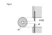
なお、図4に示すように、外套管15の基端部における案内孔21及び連通孔23には、内視鏡11等の挿入器具や湾曲シース部17の挿入時に、管路内外への空気の流出入を防ぐ薄肉ゴム等の弁体45をそれぞれ設けてある。この弁体45により、挿入先の体腔内の気腹圧等の変化が防止される。 As shown in FIG. 4, the
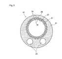
図5は内視鏡を概略的に示す外観構成図である。
内視鏡11は、本体操作部47と、この本体操作部47に連設され体腔内に挿入される内視鏡挿入部13とを備える。本体操作部47に繋がるユニバーサルコード49は、図示しない光源装置と信号処理装置に接続されて照明光や撮像信号等の入出力を行う。FIG. 5 is an external configuration diagram schematically showing the endoscope.
The
内視鏡挿入部13は、表面が樹脂材料で被覆されており、本体操作部47側から順に軟性部51、湾曲部53、及び先端部(内視鏡先端部)55で構成される。湾曲部53は、本体操作部47の湾曲操作部57(アングルノブ57A,57B)を回動することによって遠隔的に湾曲操作される湾曲作用部となる。具体的には、アングルノブ57A,57Bの回転軸にはプーリ59が同軸で設けられ、このプーリ59と内視鏡先端部55との間に、プーリ59に巻き掛けられた操作ワイヤ61が内視鏡挿入部13の内壁に沿って配置されている。この操作ワイヤ61は、内視鏡先端部55に両端が固定されている。これにより、アングルノブ57A,57Bをそれぞれ回動操作することで、操作ワイヤ61を牽引して湾曲部53を湾曲させて、内視鏡先端部55を所望の方向に向けることができる。 The
なお、図示例ではアングルノブ57Aに対応して湾曲部をθ方向に湾曲させる一系統のみ示しているが、アングルノブ57Bに対応して上記とは直交する方向(図5の紙面垂直方向)へ湾曲させる他の系も本体操作部47と内視鏡挿入部13に内蔵されている。つまり、アングルノブ57A,57Bの操作により、内視鏡先端部55を左右方向及びこれと直交する上下方向へ自在に湾曲させることができ、湾曲部53は後述するように湾曲部材として機能する。 In the illustrated example, only one system for bending the bending portion in the θ direction corresponding to the
図6に湾曲治具の外観構成図を示した。
湾曲治具19は、湾曲操作部63と、湾曲操作部63から延出され先端に湾曲自在な湾曲部65を有する中空長尺状の湾曲シース部17と、湾曲シース部17内に挿通され、一端が湾曲シース部17の先端部に固定されると共に、他端が湾曲操作部63の操作ハンドル67に固定された牽引ワイヤ69とを有する。湾曲作用部である湾曲部65は、先端駒71と複数の湾曲駒73とが連設され、各駒同士が対面する端面は、それぞれ斜めに切り欠いた切り欠き部75を有する。これら各駒71,73は、湾曲シース部17の中心軸に対して同じ側方位置でそれぞれ接続されている。また、湾曲シース部17の湾曲操作部63側の基端部には、湾曲シース部17内の牽引ワイヤ69を押し当てて固定する固定ネジ77を設けてある。FIG. 6 shows an external configuration diagram of the bending jig.
The bending
上記構成の湾曲治具19によれば、湾曲操作部63の操作ハンドル67を固定部79に対して離間操作することで、牽引ワイヤ69が湾曲シース部17内から引き出され、先端駒71と湾曲駒73の切り欠き部75の端面同士が当接するまでの間で、湾曲部65が湾曲動作される。湾曲シース部17の湾曲形状は、状態維持手段である固定ネジ77を締めることで牽引ワイヤ69が固定され、その湾曲状態を維持できる。また、固定ネジ77を緩めると湾曲状態を解除できる。 According to the bending
なお、湾曲シース部17の外周面には、長手方向に沿って目盛り79が設けられ、湾曲シース部17の挿入長さ、つまり、外套管15への長手方向挿入位置が判読可能となっている。また、湾曲シース部17は、図3に示す外套管15の連通孔23に挿通されて、外套管15を湾曲するが、この外套管15の案内孔21が外套管15の中心軸から偏心することで、案内孔21の偏心側における外套管15の肉厚が薄くなり、外套管15を湾曲させやすくなっている。 A
次に、上記構成の挿入経路確保装置100を用いて、口、肛門、膣などの人体に備わった自然孔から内視鏡を挿入し、管腔壁に小切開を加え、体腔内に到達して診断・処置を行う手技例を説明する。この手技は、腹壁切開の箇所を低減又は無くすことができる低侵襲手術であり、NOTES(Natural Orifice Translumenal Endoscopic Surgery:経管腔的内視鏡手術)と呼ばれる。 Next, using the insertion
図7A〜図7Fに本挿入経路確保装置100を用いた経膣手技(経膣での胃腫瘍の摘出)の手順の一例を段階的に示した。
まず、患者の腹膜壁を介して腹腔鏡81を挿入し、患者の膣Vaから体表組織切開用のトロカール83を挿入する。トロカール83を後膣円蓋に到達させ、腹腔鏡81により確認しながら切開して一部を体腔内に挿入する(図7A)。FIG. 7A to FIG. 7F show an example of a procedure of a transvaginal procedure (extracting a gastric tumor through the vagina) using the insertion
First, a
トロカール83を患者の膣Vaから抜き取り、図2に示すように、内視鏡(内視鏡挿入部13)が外套管15の案内孔21に挿入された状態の挿入経路確保装置100を患者の膣Vaから挿入する(図7B)。 The
腹腔鏡81により、外套管15、内視鏡先端部55が適切な位置であることを確認後、腹腔鏡81を抜き取る。 After confirming that the
腹腔鏡81を挿入していた腹膜壁のポートから圧排子85を挿入し、挿入経路確保装置100の進路上にある組織を移動して進路を確保する。(図7C)。 The
更に必要に応じて経口により胃S内へ内視鏡87を進入させ、以内の病変位置を確認する(図7D)。 Furthermore, if necessary, the
内視鏡の鉗子口を経由して高周波切開具などを挿入し、胃Sを支持する周辺組織を切開し、胃を移動可能な状態にする。その後、外套管15に挿入された内視鏡を抜き取り、外套管15の空いた案内孔21にステープラー89を挿入し、腹腔鏡81による観察下で、患部を切除する(図7E)。 A high-frequency incision tool or the like is inserted through the forceps opening of the endoscope, and the surrounding tissue supporting the stomach S is incised to make the stomach movable. Thereafter, the endoscope inserted into the
ステープラー89を外套管15から抜き取り、外套管15の空いた案内孔21に再び内視鏡を挿入する。腹腔鏡81による観察下で、内視鏡の鉗子孔に挿入した回収鉗子91により切除患部Scを摘み、体腔外に回収する(図7F)。 The
上記の一例として示した手技を行う際、図8に示すように挿入経路確保装置100の外套管15は、膣Va内での挿入方向に沿って進むと、外套管15の先端が、患者の仙骨SSの特に岬角と呼ばれる突出した部位に接触し、又は圧迫してしまう場合がある。そのため、図中点線で示すように、外套管15を湾曲させて仙骨SSを回避させることが望ましい。その際、目的患部である胃Sの位置は、外套管15の湾曲後の先端が向く方向Daでなく、方向Daとは異なる方向Db上にあるため、図中一点鎖線で示すように、外套管15を更に1回湾曲させる必要がある。 When performing the procedure shown as an example above, as shown in FIG. 8, when the
そこで、本挿入経路確保装置100においては、外套管15を湾曲させる際に、複数の湾曲点が形成される外套管15の湾曲形状を確実に保持するため、各湾曲点に湾曲機能部材をそれぞれ配置することで、外套管15が最終的な湾曲形状に固定されるまでの湾曲形成途中で、各湾曲点における湾曲形状を確実に保持する機能を付与している。 Therefore, in the insertion
以下に、この挿入経路確保装置100による挿入経路確保の手順の例を順次説明する。ここでは、経膣により胃の腫瘍を摘出する場合の挿入経路の確保の様子を示す。
<第1の挿入経路確保手順>
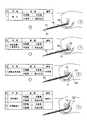
図9及び図10に第1の挿入経路確保手順の説明図を示した。
各図においては、内視鏡(内視鏡挿入部13)、外套管15、湾曲治具(湾曲シース部17)19の曲げ剛性(以下、硬度と称する)の相対関係を各挿入ステップ毎に示している。Hereinafter, an example of a procedure for securing an insertion path by the insertion
<First insertion path securing procedure>
FIGS. 9 and 10 are explanatory diagrams of the first insertion path securing procedure.
In each figure, the relative relationship of the bending rigidity (hereinafter referred to as hardness) of the endoscope (endoscope insertion portion 13),
外套管15の硬度は、柔軟な軟性状態と、形状を固定する剛性状態との間で変更でき、湾曲治具の硬度は、図6に示す湾曲部65を牽引ワイヤ69の牽引により湾曲させた場合と、牽引を解除した通常状態との間で変更される。また、内視鏡の硬度は、図5に示す湾曲部53をフリー状態にした場合と、アングルノブ57を操作して湾曲部53の湾曲角を規定している場合(湾曲角をロックした状態を含む)との間で変更される。 The hardness of the
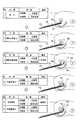
まず、図9に示すSt.1から順に説明する。
(St.1 挿入)
外套管15に内視鏡挿入部13及び湾曲シース部17を挿入した状態で、外套管15を直線形状で剛性状態にして固定する。この直線形状とされた外套管15を患者の膣Vaに挿入し、トロカールにより穿刺された後膣円蓋(図7A参照)から体腔内に先端を進入させる。このときの外套管15の硬度は湾曲シース部17より大きくされ、安定した挿入動作を確保している。なお、外套管15の硬度は、内視鏡挿入部13の曲げ剛性に対して特に規定されず、外套管15を膣Vaに挿入した後に内視鏡挿入部13を外套管15内に挿入してもよい。内視鏡挿入部13を外套管15に挿入した状態で膣Vaに挿入する場合は、外套管15の硬度を湾曲シース部17に近い程度に低下させることも可能である。First, as shown in FIG. The description will be made sequentially from 1.
(St.1 insertion)
In a state where the
(St.2 湾曲治具進入)
外套管15の硬度を湾曲シース部17より小さくして、外套管15の先端から湾曲シース部17を体腔内に進入させる。このときの湾曲シース部17の進入長さは、仙骨SSに到達しない程度に留める。(St.2 Entering bending jig)
The hardness of the
(St.3 湾曲治具湾曲)
直線形状の外套管15の延長上にある仙骨SSが、確保しようとする挿入経路から回避されるように、外套管15から突出させた湾曲シース部17を湾曲させる。この湾曲位置が、確保しようとする挿入経路の一次湾曲点P1となる。(St.3 Bending jig bending)
The
(St.4 外套管進入)
軟性化された外套管15を、先端が湾曲された湾曲シース部17の先端まで、湾曲シース部17に沿って進入させ、外套管15を湾曲シース部17によって湾曲させる。このとき、外套管15は内視鏡挿入部13が挿入されていない領域で湾曲されるので、湾曲操作が容易に行える。(St.4 Mantle tube approach)
The softened
(St.5 形状固定)
外套管15を一次湾曲点P1で湾曲させた状態で、外套管15の硬度を湾曲シース部17より大きくする。(St.5 shape fixed)
In a state where the
(St.6 内視鏡進入)
内視鏡挿入部13を、湾曲された外套管15に沿って進入させ、外套管15の先端から突出させる。なお、内視鏡挿入部13は、湾曲シース部17よりも柔らかい状態であるため、外套管15の硬度を大きくする形状固定ステップSt.5は省略することもできる。(St.6 Endoscope entry)
The
(St.7 内視鏡湾曲)
図10に示すように、確保しようとする挿入経路が胃Sに向かうように内視鏡挿入部13を湾曲させる。この湾曲位置が、確保しようとする挿入経路の二次湾曲点P2となる。(この二次湾曲点P2は、内視鏡挿入部13を外套管15と一緒に進入させた状態で湾曲させても良い)このときの一次湾曲点P1では、湾曲シース部17が湾曲形状を保持し続けている。(St.7 Endoscopic curvature)
As shown in FIG. 10, the
(St.8 外套管進入)
外套管15を、先端が湾曲された内視鏡挿入部13に沿って進入させ、外套管15を内視鏡挿入部13によって湾曲させる。ここで外套管15は、一次湾曲、二次湾曲されたS字状に変形される。外套管15が二次湾曲点P2において湾曲形状を形成する際、一次湾曲点P1では湾曲シース部17が一次湾曲の湾曲形状を保持しているため、外套管15の一次湾曲点P1における湾曲形状は崩れることがない。(St.8 Mantle tube approach)
The
(St.9 外套管進入)
一次湾曲点P1の湾曲形状を湾曲シース部17で保持し、二次湾曲点P2の湾曲形状を内視鏡挿入部13により保持した状態で、外套管15を更に胃Sの近傍位置まで進入させる。(St.9 Mantle tube approach)
With the curved shape of the primary bending point P1 held by the bending
(St.10 形状固定・内視鏡進入)
湾曲シース部17及び内視鏡挿入部13によりS次状に湾曲された外套管15の硬度を大きくして、外套管15の形状を固定する。これにより、膣Vaから胃Sまでの挿入経路が外套管15により確保される。そして、内視鏡挿入部13を更に進入させて、内視鏡先端部を胃Sに接近させる。(St.10 Shape fixing / endoscopy)
The hardness of the
ここで、上記した外套管15の軟性状態とは、湾曲シース部17を外套管15の遠位端より遠位側に配置した状態で湾曲させ、湾曲した湾曲シース部17に沿って外套管15を進めることで、外套管15を湾曲させることが可能な状態であり、剛性状態とは、内視鏡挿入部13を外套管15に沿って挿通する際に湾曲シース部17によって付与された湾曲形状を維持することが可能な状態として表すことができる。 Here, the above-described soft state of the
上記第1の挿入経路確保手順によれば、挿入経路が一次湾曲点P1、二次湾曲点P2の複数の湾曲点を有する場合でも、外套管15を最終的な湾曲形状に形成するまでの間、外套管15内の範囲において、それぞれの湾曲点P1,P2の湾曲形状の規制を常時保持させることができ、外套管15の各湾曲点P1,P2の湾曲形状が湾曲形成途中で崩れることを防止できる。即ち、湾曲点P2の湾曲を規制する際に、湾曲点P1の湾曲の規制が解除されることがなくなり、各湾曲点P1,P2の湾曲形状が正確に保持できる。 According to the first insertion path securing procedure, even when the insertion path has a plurality of bending points of the primary bending point P1 and the secondary bending point P2, the time until the
また、湾曲機能部材として、湾曲治具19(湾曲部65)及び内視鏡11(湾曲部53)等、複数備えることで、それぞれの湾曲機能部材を個別に、しかも異なるタイミングで制御できる。例えば、一旦設定した湾曲機能部材の湾曲形状を、外套管15の湾曲形状の形成途中で更に設定し直すこともできる。これにより、湾曲シース部17による湾曲形状に経時変化が生じた場合でも、この変化を随時是正して所望の湾曲形状を確実に保持できる。また、外套管15の湾曲形状の形成途中で、一旦設定した湾曲曲率を更に小さく、又は大きくする等の湾曲位置毎の細かな調整が簡単に行える。 Further, by providing a plurality of bending function members such as the bending jig 19 (the bending portion 65) and the endoscope 11 (the bending portion 53), each bending function member can be controlled individually and at different timings. For example, the bending shape of the bending function member once set can be further reset during the formation of the bending shape of the
これにより、湾曲治具と内視鏡によって規制した通りの外套管15の湾曲形状が、挿入経路確保後も正確に保持されて、挿入経路周囲の臓器や器官との不要な接触を防止できる。 Thereby, the curved shape of the
また、挿入経路確保後は、湾曲シース部17を外套管15から抜き取ることで、この湾曲シース部17が挿通されていた外套管15の連通孔23(図2参照)が他の用途、例えばカテーテルの挿入等に利用可能となり、マルチルーメン構造を活かして手技範囲を拡げることができる。 Further, after securing the insertion path, the
上記の外套管15の構成では、確保しようとする挿入経路が、一次湾曲点P1と二次湾曲点P2との2箇所であるため、湾曲治具19及び内視鏡の湾曲部53(図5参照)の2つの湾曲機能部材のみ用いていたが、湾曲機能部材の数は、必要な湾曲点の数に応じて増やすことができる。例えば、外套管15の連通孔23(図2参照)の数を2本から任意の複数本に増加させ、各連通孔23のそれぞれに湾曲治具19を挿通させる等、適宜な変更が可能である。 In the above-described configuration of the
また、湾曲機能部材として内視鏡の湾曲部53を用いる場合は、内視鏡で観察しながら湾曲形状を調整でき、手技内容を簡単化してより正確な湾曲形状を形成できる。勿論、内視鏡の湾曲部53を用いずに、複数の湾曲治具19で湾曲形状を形成する場合には、湾曲治具19の操作によって湾曲形状をより細かに調整でき、挿入経路を確保した後は、外套管15から湾曲治具19を抜き取ることができるため、上記のマルチルーメン構造による効果も得られる。 When the bending
なお、上記例は経膣の場合であるが、経胃、経直腸の場合も同様であり、更に、腹腔等の切開により挿入する場合でも同様の作用効果が得られる。 The above example is for the case of transvaginal, but the same applies to the case of transgastric and transrectal, and the same action and effect can be obtained even when inserted through incision of the abdominal cavity or the like.
<第2の挿入経路確保手順>
次に、第2の挿入経路確保手順を説明する。
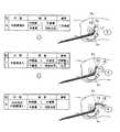
図11及び図12に第2の挿入経路確保手順の説明図を示した。
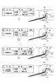
まず、図11に示すSt.1から順に説明する。
(St.1 挿入)
前述同様に、外套管15に内視鏡挿入部13及び湾曲シース部17を挿入した外套管15を直線形状にして患者の膣Vaに挿入し、後膣円蓋から体腔内に外套管15の先端を進入させる。このときの外套管15の硬度は湾曲シース部17より大きくされ、安定した挿入動作を確保している。なお、外套管15の硬度は、内視鏡挿入部13の曲げ剛性に対して特に規定されず、外套管15を膣Vaに挿入した後に外套管15内に挿入してもよい。内視鏡挿入部13を外套管15に挿入した状態で膣Vaに挿入する場合は、外套管15の硬度を湾曲シース部17に近い程度に低下させることも可能である。<Second insertion path securing procedure>
Next, a second insertion path securing procedure will be described.
FIG. 11 and FIG. 12 are explanatory diagrams of the second insertion path securing procedure.
First, as shown in FIG. The description will be made sequentially from 1.
(St.1 insertion)
As described above, the
(St.2 湾曲治具・外套管進入)
外套管15の硬度を湾曲シース部17より小さくして、外套管15と湾曲シース部17とを共に体腔内に進入させる。このとき、内視鏡挿入部13はSt.1の位置に留めておく。(St.2 Curved jig / mantle tube approach)
The hardness of the
(St.3 湾曲治具湾曲)
内視鏡挿入部13の先端から突出された湾曲シース部17を、仙骨SSを回避するように外套管15と共に湾曲させる。この湾曲位置が、確保しようとする挿入経路の一次湾曲点P1となる。(St.3 Bending jig bending)
The bending
(St.4 形状固定)
外套管15を一次湾曲点P1で湾曲させた状態で、外套管15の硬度を湾曲シース部17より大きくする。(St.4 shape fixed)
In a state where the
(St.5 内視鏡挿入)
内視鏡挿入部13を、湾曲された外套管15に沿って進入させ、外套管15の先端から突出させる。なお、内視鏡挿入部13は、湾曲シース部17よりも柔らかい状態であるため、外套管15の硬度を大きくする形状固定ステップSt.5は省略することもできる。(St.5 Endoscope insertion)
The
(St.6 内視鏡湾曲)
図12に示すように、確保しようとする挿入経路が胃Sに向かうように内視鏡挿入部13を湾曲させる。この湾曲位置が、確保しようとする挿入経路の二次湾曲点P2となる。このときの一次湾曲点P1では、湾曲シース部17が湾曲形状を保持し続けている。(St.6 Endoscopic curvature)
As shown in FIG. 12, the
(St.7 外套管進入)
外套管15を、先端が湾曲された内視鏡挿入部13に沿って進入させ、外套管15を内視鏡挿入部13によって湾曲させる。ここで外套管15は、一次湾曲、二次湾曲されたS字状に変形される。外套管15が二次湾曲点P2において湾曲形状を形成する際、一次湾曲点P1では湾曲シース部17が一次湾曲の湾曲形状を保持しているため、外套管15の一次湾曲点P1における湾曲形状は崩れることがない。そして、外套管15を更に胃Sの近傍位置まで進入させる。(この二次湾曲点P2は、内視鏡挿入部13を外套管15と一緒に進入した状態で湾曲させても良い)。(St.7 Mantle tube approach)
The
(St.8 形状固定・内視鏡進入)
一次湾曲点P1の湾曲形状を湾曲シース部17で保持し、二次湾曲点P2の湾曲形状を内視鏡挿入部13により保持した状態で、外套管15の硬度を大きくして外套管15の形状を固定する。これにより、膣Vaから胃Sまでの挿入経路が外套管15により確保される。そして、内視鏡挿入部13を更に進入させて、内視鏡先端部を胃Sに接近させる。(St.8 Shape fixation / endoscopy)
In a state where the curved shape of the primary bending point P1 is held by the bending
ここで、上記した外套管15の軟性状態とは、湾曲シース部17を外套管15の遠位端よりも近位側に配置した状態で、湾曲シース部17を操作することで外套管15を湾曲させることが可能な状態であり、剛性状態とは、内視鏡挿入部13を外套管15に沿って挿通する際に湾曲シース部17によって付与された湾曲形状を維持することが可能な状態として表すことができる。 Here, the soft state of the
上記第2の挿入経路確保手順によれば、一次湾曲点P1における外套管15の湾曲形成時に、湾曲シース部17と外套管15とが一体になって湾曲されるため、外套管15、即ち挿入経路を直接に湾曲させることができ、湾曲形状をより正確に設定することができる。 According to the second insertion path securing procedure, the
<第3の挿入経路確保手順>
次に、第3の挿入経路確保手順を説明する。
図13に第3の挿入経路確保手順の説明図を示した。
(St.1 挿入)
前述同様に、外套管15に内視鏡挿入部13及び湾曲シース部17を挿入した外套管15を直線形状にして患者の膣Vaに挿入し、後膣円蓋から体腔内に外套管15の先端を進入させる。このときの外套管15の硬度は、少なくとも湾曲シース部17より大きくされ、安定した挿入動作を確保している。なお、外套管15の硬度は、内視鏡挿入部13の曲げ剛性に対して特に規定されず、外套管15を膣Vaに挿入した後に内視鏡挿入部13を外套管15内に挿入してもよい。<Third insertion path securing procedure>
Next, a third insertion path securing procedure will be described.
FIG. 13 shows an explanatory diagram of the third insertion path securing procedure.
(St.1 insertion)
As described above, the
(St.2 湾曲治具・内視鏡進入)
外套管15の硬度を内視鏡挿入部13及び湾曲シース部17より小さくして、内視鏡挿入部13と湾曲シース部17とを共に体腔内に進入させる。このとき、外套管15はSt.1の位置に留めておく。(St.2 Bending jig / endoscopy)
The hardness of the
(St.3 湾曲治具湾曲)
外套管15の先端から突出された湾曲シース部17を、仙骨SSを回避するように湾曲させる。この湾曲位置が、確保しようとする挿入経路の一次湾曲点P1となる。このときの湾曲シース部17の湾曲動作は、内視鏡による観察の下で行える。そして、内視鏡挿入部13は、湾曲シース部17の湾曲動作後に、湾曲シース部17と略同じ湾曲状態にする。(St.3 Bending jig bending)
The
(St.4 外套管進入)
軟性化された外套管15を、先端が湾曲された湾曲シース部17及び内視鏡挿入部13の先端まで、湾曲シース部17及び内視鏡挿入部13に沿って進入させ、外套管15を湾曲させる。(St.4 Mantle tube approach)
The softened
(St.5 形状固定)
外套管15を一次湾曲点P1で湾曲させた状態で、外套管15の硬度を内視鏡挿入部13及び湾曲シース部17より大きくする。(St.5 shape fixed)
In a state where the
(St.6 内視鏡進入)
内視鏡挿入部13を進入させ、外套管15の先端から突出させる。なお、内視鏡挿入部13は、湾曲シース部17よりも柔らかい状態であるため、外套管15の硬度を大きくする形状固定ステップSt.5は省略することもできる。(St.6 Endoscope entry)
The
以降のSt.7〜St.10は、第1の挿入経路確保手順と同様であり、図10に示す通りになる。
上記第3の挿入経路確保手順によれば、挿入経路の一次湾曲点P1における湾曲時に、湾曲治具による湾曲状態を内視鏡により観察しながら調整できる。したがって、一次湾曲点P1における湾曲形状を視覚情報に基づいてより正確に設定することができ、手技を簡単化できる。Subsequent St. 7-St. 10 is the same as the first insertion path securing procedure, as shown in FIG.
According to the third insertion path securing procedure, the bending state by the bending jig can be adjusted while observing with the endoscope at the time of bending at the primary bending point P1 of the insertion path. Therefore, the bending shape at the primary bending point P1 can be set more accurately based on the visual information, and the procedure can be simplified.
<第4の挿入経路確保手順>
次に、第4の挿入経路確保手順を説明する。
図14に第4の挿入経路確保手順の説明図を示した。<Fourth insertion path securing procedure>
Next, a fourth insertion path securing procedure will be described.
FIG. 14 shows an explanatory diagram of the fourth insertion path securing procedure.
(St.1 挿入)
前述同様に、外套管15に内視鏡挿入部13及び湾曲シース部17を挿入した外套管15を直線形状で剛性状態にして患者の膣Vaに挿入し、後膣円蓋から体腔内に外套管15の先端を進入させる。このときの外套管15の硬度は少なくとも内視鏡挿入部13より大きくされ、安定した挿入動作を確保している。なお、外套管15の硬度は、湾曲シース部17の曲げ剛性に対して特に規定されず、外套管15を膣Vaに挿入した後に湾曲シース部17を外套管15内に挿入してもよい。(St.1 insertion)
In the same manner as described above, the
(St.2 内視鏡進入)
外套管15の硬度を内視鏡挿入部13より小さくして、内視鏡挿入部13を体腔内に進入させる。このとき、外套管15及び湾曲シース部17はSt.1の位置に留めておく。(St.2 Endoscope entry)
The hardness of the
(St.3 内視鏡湾曲)
外套管15の先端から突出された内視鏡挿入部13の先端を、仙骨SSを回避するように湾曲させる。この湾曲位置が、確保しようとする挿入経路の一次湾曲点P1となる。このときの湾曲動作は、内視鏡により観察しながら行うため、湾曲の調整が容易となる。(St.3 Endoscopic curvature)
The distal end of the
(St.4 外套管・湾曲治具進入)
軟性化された外套管15及び湾曲シース部17を、先端が湾曲された内視鏡挿入部13の先端まで、内視鏡挿入部13に沿って進入させ、外套管15を湾曲させる。(St.4 Mantle tube / bending jig approach)
The softened
(St.5 形状固定)
外套管15を一次湾曲点P1で湾曲させた状態で、外套管15の硬度を内視鏡挿入部13及び湾曲シース部17より大きくする。このとき、湾曲シース部17を、硬化した外套管15の湾曲形状、即ち、内視鏡挿入部13の一次湾曲点P1における湾曲形状を保持させる。(St.5 shape fixed)
In a state where the
(St.6 内視鏡進入)
外套管15の硬度を内視鏡挿入部13及び湾曲シース部17より小さくして、内視鏡挿入部13を進入させ、外套管15の先端から突出させる。このときの湾曲シース部17は一次湾曲点P1における湾曲形状を保持しているので、外套管15を軟性化させても一次湾曲点P1の湾曲形状が崩れることはない。なお、内視鏡挿入部13は、湾曲シース部17より柔らかい状態であるため、外套管15の硬度を大きくする形状固定ステップSt.5は省略することもできる。(St.6 Endoscope entry)
The hardness of the
以降のSt.7〜St.10は、第1の挿入経路確保手順と同様であり、図10に示す通りになる。
上記第4の挿入経路確保手順によれば、内視鏡挿入部13が常に挿入先の先頭となって進入するため、常に観察しながら挿入経路を決定できる。このため、一次湾曲点P1及び二次湾曲点P2の湾曲形状を視覚情報に基づいてより正確に設定でき、手技を簡単化できる。Subsequent St. 7-St. 10 is the same as the first insertion path securing procedure, as shown in FIG.
According to the fourth insertion path securing procedure, the
<第5の挿入経路確保手順>
次に、第5の挿入経路確保手順を説明する。
図15に第5の挿入経路確保手順の説明図を示した。ここでは、図5に示す内視鏡挿入部13をS字型に湾曲可能な内視鏡を用いる。具体的には、例えば湾曲部53を2箇所に設け、湾曲操作部57からの操作によって互いに異なる方向に湾曲する構成にすれば、内視鏡挿入部をS字型に湾曲可能となる。<Fifth insertion path securing procedure>
Next, a fifth insertion path securing procedure will be described.
FIG. 15 shows an explanatory diagram of the fifth insertion path securing procedure. Here, an endoscope capable of bending the
(St.1 挿入)
外套管15に内視鏡挿入部13Aを挿入した外套管15を直線形状で剛性状態にして患者の膣Vaに挿入し、後膣円蓋から体腔内に外套管15の先端を進入させる。このときの外套管15の硬度は、内視鏡挿入部13Aより大きくされ安定した挿入動作を確保している。(St.1 insertion)
The
(St.2 内視鏡進入)
外套管15の硬度を内視鏡挿入部13Aより小さくして、内視鏡挿入部13Aを体腔内に進入させる。このとき、外套管15はSt.1の位置に留めておく。(St.2 Endoscope entry)
The hardness of the
(St.3 内視鏡湾曲)
外套管15の先端から突出された内視鏡挿入部13Aの先端を、仙骨SSを回避するようにS字型に湾曲させる。このときの各湾曲位置が、確保しようとする挿入経路の一次湾曲点P1、二次湾曲点P2となる。なお、この湾曲動作は、内視鏡により観察しながら行うため、湾曲の調整が容易となる。(St.3 Endoscopic curvature)
The distal end of the
(St.4 外套管進入)
軟性化された外套管15を、先端がS字型に湾曲された内視鏡挿入部13Aの先端まで、内視鏡挿入部13Aに沿って進入させ、外套管15をS字型に湾曲させる。(St.4 Mantle tube approach)
The softened
(St.5 形状固定)
外套管15を一次湾曲点P1及び二次湾曲点P2で湾曲させた状態で、外套管15の硬度を内視鏡挿入部13Aより小さくする。このとき、内視鏡挿入部13Aが一次湾曲点P1及び二次湾曲点P2の湾曲形状を保持するため、各湾曲点P1,P2の湾曲形状が崩れることはない。(St.5 shape fixed)
In a state where the
(St.6 内視鏡進入)
内視鏡挿入部13Aを、湾曲部53(図5参照)をフリー状態として体腔内に進入させ、内視鏡先端部を胃Sに接近させる。(St.6 Endoscope entry)
The
上記第5の挿入経路確保手順によれば、内視鏡挿入部13Aが一度に一次湾曲点P1及び二次湾曲点P2の湾曲形状に一致させるので、簡単な手技により外套管15を所望の挿入経路の形状に湾曲させることができる。 According to the fifth insertion path securing procedure, the
以上説明した各挿入経路確保装置による挿入経路の確保手順によれば、外套管15を湾曲させる際に、湾曲点の位置毎に外套管15の湾曲状態を複数の湾曲部材により保持するので、外套管15の湾曲形成が全て完了するまでは、各湾曲点における湾曲形状が確実に保持される。これにより、挿入経路が規定の湾曲形状から変化することを防止できる。 According to the procedure for securing the insertion path by each of the insertion path securing devices described above, when the
次に、挿入経路確保装置100の他の構成例を変形例として説明する。
<変形例1>
図16は外套管の体腔内挿入側の先端部における断面図である。外套管15Aの案内孔21には内視鏡挿入部13が挿通され、外套管15Aの体腔内挿入側から突出した内視鏡挿入部13は、所望の方向へ湾曲される。内視鏡挿入部13の表面は樹脂チューブで覆われており、この樹脂チューブには、内視鏡挿入部13の湾曲により周方向に連続する皺(突条)95が生じる。皺95は、内視鏡挿入部13を案内孔21内で挿抜する際に、案内孔21の体腔内挿入側端部97に当接し、引っ掛かりによる抵抗を生じやすくなる。Next, another configuration example of the insertion
<
FIG. 16 is a cross-sectional view of the distal end portion of the outer tube on the insertion side in the body cavity. The
そこで、この外套管15Aにおいては、案内孔21の体腔内挿入側端部97の内壁に、案内孔21の内径が体腔内挿入側端部97に向けて拡径するテーパ部99Aを設けてある。これにより、湾曲した内視鏡挿入部13を案内孔21内で挿抜する際に、皺95がテーパ部99Aによって容易に乗り越えて、引っ掛かりがなくなる。よって、内視鏡挿入部13の円滑な挿抜が行え、内視鏡の手技の操作感を向上できる。 Therefore, in the
<変形例2>
図17は外套管の体腔内挿入側の先端部における一部断面斜視図である。外套管15Bは、体腔内挿入側の外周面に、案内孔21と連通する複数の開口孔111が穿設されている。開口孔113は、内視鏡挿入部13の先端部の観察窓113及び照明窓115の覗き孔となって、案内孔21から内視鏡挿入部13の先端が突出する手前位置から周囲の観察が可能となる。<
FIG. 17 is a partial cross-sectional perspective view of the distal end portion of the outer tube on the insertion side in the body cavity. In the
この構成によれば、外套管15Bを透光性材料で形成せずとも、案内孔21内からの内視鏡観察が可能となり、外套管15Bの材料選択の自由度が高められる。また、外套管15Bが透光性材料からなる場合は、案内孔21内からの内視鏡観察時に、開口孔111を通して鮮明度の高い周囲画像が得られる。 According to this configuration, it is possible to perform endoscopic observation from the
<変形例3>
図18は外套管の断面図である。外套管は、図3に示す断面形状に限らず図18に示す薄肉の断面形状にできる。即ち、外套管15Cは、連通孔23,23を案内孔21の外周側にそれぞれ個別に配置して、案内孔21の外周を薄肉化した構成としている。この構成によれば、細径化が図れ、体腔内のより狭い孔に進入させることが可能となる。なお、図示例では連通孔23,23を一例として2箇所に設けてあるが、更に他の連通孔を設けてもよい。<
FIG. 18 is a cross-sectional view of the mantle tube. The outer tube is not limited to the cross-sectional shape shown in FIG. 3, but can be a thin cross-sectional shape shown in FIG. That is, the
<変形例4>
図19は湾曲治具の湾曲部材の先端部分を示す斜視図である。この湾曲シース部17Aは、前述の断面円形の湾曲シース部17に代えて、表裏面の断面形状が円弧状の湾曲板状で、長手方向に沿った板厚内に牽引ワイヤ69が挿通された長尺状の部材となっている。<
FIG. 19 is a perspective view showing a tip portion of a bending member of the bending jig. In this
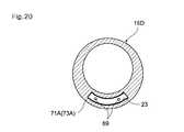
湾曲シース部17Aの先端の湾曲部65は、先端駒71Aと、複数の湾曲駒73Aとが連接されており、各駒同士が対面する端面は、前述と同様の切り欠き部75を有する。この切り欠き部75によって、牽引ワイヤ69を牽引したときに湾曲部65が湾曲動作される。この湾曲シース部17Aは、図20に断面形状を示す外套管15Dの連通孔23に挿入され、外套管15Dを湾曲させる。 The bending
外套管15Dに形成する連通孔23は、図示例のように1つに限らず、複数箇所に設けた構成としてもよい。また、図21に示すように、外套管15の断面形状を、案内孔21の外周を薄肉化させて、外套管15を細く、湾曲させやすくした構成としてもよい。 The number of communication holes 23 formed in the
<変形例5>
図22は湾曲治具の湾曲部材の先端部分を示す斜視図である。この湾曲シース部17Bは、前述の断面円形の湾曲シース部17に代えて、断面円筒形状で図中上下双方に先端部が湾曲可能な長尺状の部材となっている。湾曲シース部17Bの先端の湾曲部65は、先端駒71Bと、複数の湾曲駒73Bとが連設されており、各駒同士は直径方向2箇所(図中手前側の当接点117と図示しない奥側の当接点)の円周位置で互いに当接している。そして、この直径方向に直交する面内で湾曲可能にする一対の切り欠き部75A,75Bが各駒の端部に形成されている。<
FIG. 22 is a perspective view showing a tip portion of a bending member of the bending jig. The
即ち、湾曲部65を図中上方向に湾曲させるときは上側の牽引ワイヤ69Aを牽引し、下方向に湾曲させるときは下側の牽引ワイヤ69Bを牽引する。この湾曲シース部17Bは、図23に断面形状を示す外套管15Fの連通孔119に挿入され、外套管15Fを湾曲させる。 That is, when the bending
なお、外套管は、柔軟な軟性状態と、形状が固定される剛性状態との間で硬度が可変な上記構成例に限らず、外套管に、案内孔(第1のルーメン)や連通孔(第2のルーメン)に加えて第3のルーメンを設け、この第3のルーメン内に、前述の外套管15と同様の原理で硬度が可変な長尺状の硬度可変部材を挿入し、外套管の硬度を変更する構成としてもよい。その場合には、外套管自身に硬度を可変にする機能を付与する必要がなく、外套管の構成を簡略化できる。また、外套管の内側に湾曲部材を設けた構成に限らず、外套管の外側に湾曲部材を配置した構成としてもよい。 The outer tube is not limited to the above configuration example in which the hardness is variable between a soft and flexible state and a rigid state in which the shape is fixed, but the outer tube is provided with a guide hole (first lumen) or a communication hole ( In addition to the second lumen), a third lumen is provided, and a long hardness variable member whose hardness is variable on the same principle as the
本発明は上記の実施形態に限定されるものではなく、明細書の記載、並びに周知の技術に基づいて、当業者が変更、応用することも本発明の予定するところであり、保護を求める範囲に含まれる。 The present invention is not limited to the above-described embodiments, and those skilled in the art can change or apply the present invention based on the description of the specification and well-known techniques. included.
以上の通り、本明細書には次の事項が開示されている。
(1) 長手軸を有する挿入部により、体腔内へ挿入される挿入器具を案内する挿入経路確保装置であって、
前記挿入部の長手軸に沿って進退自在に配置され、遠位側に設けられた第1の湾曲作用部と近位側に設けられた第1の湾曲操作部とを有し、前記第1の湾曲操作部を操作することで前記第1の湾曲作用部を湾曲可能な第1の湾曲部材と、
前記挿入部の長手軸に沿って進退自在に配置され、遠位側に設けられた第2の湾曲作用部と近位側に設けられた第2の湾曲操作部とを有し、前記第2の湾曲操作部を操作することで、前記長手軸上で前記第1の湾曲部材とは異なる位置で前記第2の湾曲作用部を湾曲可能な第2の湾曲部材と、
前記挿入部の長手軸に沿って配置され、遠位側に設けられた硬度可変部と近位側に設けられた硬度変更操作部とを有し、前記硬度可変部は前記硬度変更操作部の操作により前記第1の湾曲部材若しくは第2の湾曲部材によって湾曲可能な柔軟性を前記挿入部に付与する軟性状態と、前記第1の湾曲部材若しくは第2の湾曲部材によって前記挿入部に与えられた湾曲形状を維持する剛性状態と、に硬度を変更することができる硬度変更部材と、
を備えた挿入経路確保装置。
この挿入経路確保装置によれば、第1の湾曲部材と第2の湾曲部材によって長手軸上の挿入部の異なる位置を湾曲させる際に、各湾曲位置における湾曲形状を確実に維持して挿入経路を形成することができる。As described above, the following items are disclosed in this specification.
(1) An insertion path securing device for guiding an insertion instrument to be inserted into a body cavity by an insertion portion having a longitudinal axis,
A first bending action portion provided on the distal side and a first bending operation portion provided on the proximal side, which are disposed so as to be movable back and forth along the longitudinal axis of the insertion portion; A first bending member capable of bending the first bending operation unit by operating the bending operation unit;
A second bending action portion provided on the distal side and a second bending operation portion provided on the proximal side, which are disposed so as to be movable back and forth along the longitudinal axis of the insertion portion; A second bending member capable of bending the second bending action portion at a position different from the first bending member on the longitudinal axis,
A hardness varying portion provided on the distal side and a hardness changing operation portion provided on the proximal side are disposed along the longitudinal axis of the insertion portion, and the hardness varying portion is provided on the hardness changing operation portion. A soft state in which the insertion portion is provided with a flexibility that can be bent by the first bending member or the second bending member by an operation, and the insertion portion is provided to the insertion portion by the first bending member or the second bending member. A rigid state that maintains a curved shape, and a hardness changing member that can change the hardness,
An insertion path securing device comprising:
According to this insertion path securing device, when the different positions of the insertion portion on the longitudinal axis are bent by the first bending member and the second bending member, the insertion path is ensured by maintaining the bending shape at each bending position. Can be formed.
(2) (1)に記載の挿入経路確保装置であって、
前記硬度変更部材の前記軟性状態は、前記第1の湾曲作用部を前記硬度変更部材の遠位端より遠位側に配置した状態で湾曲させ、前記湾曲した前記第1の湾曲作用部に沿って前記硬度変更部材を進めることで、前記硬度変更部材を湾曲させることが可能な状態であり、前記剛性状態は、前記第2の湾曲部材を前記硬度変更部材に沿って挿通する際に前記第1の湾曲部材によって付与された湾曲形状を維持することが可能な状態である挿入路確保装置。
この挿入経路確保装置によれば、軟性状態の硬度変更部材が第1の湾曲作用部に沿って進められて湾曲し、この湾曲後に硬度変更部材を剛性状態にされるため、第2の湾曲部材を硬度変更部材に沿って挿通する場合に、第1の湾曲部材によって硬度変更部材に付与された湾曲形状が維持できる。(2) The insertion path securing device according to (1),
The softness state of the hardness changing member is bent along the curved first bending action portion in a state where the first bending action portion is arranged on the distal side of the distal end of the hardness changing member. The hardness changing member can be bent by advancing the hardness changing member, and the rigidity state is determined when the second bending member is inserted along the hardness changing member. An insertion path securing device that is capable of maintaining the curved shape imparted by one bending member.
According to this insertion path securing device, the hardness changing member in the soft state is advanced along the first bending action portion to bend, and the hardness changing member is made to be in a rigid state after this bending. Can be maintained along the hardness changing member, the curved shape imparted to the hardness changing member by the first bending member can be maintained.
(3) (1)に記載の挿入経路確保装置であって、
前記硬度変更部材の前記軟性状態は、前記第1の湾曲作用部を前記硬度変更部材の遠位端よりも近位側に配置した状態で、前記第1の湾曲操作部を操作することで前記硬度変更部材を湾曲させることが可能な状態であり、前記剛性状態は、前記第2の湾曲部材を前記硬度変更部材に沿って挿通する際に前記第1の湾曲部材によって付与された湾曲形状を維持することが可能な状態である挿入路確保装置。
この挿入経路確保装置によれば、軟性状態の硬度変更部材が第1の湾曲作用部の湾曲操作によって湾曲し、この湾曲後に硬度変更部材を剛性状態にされるため、第2の湾曲部材を硬度変更部材に沿って挿通する場合に、第1の湾曲部材によって硬度変更部材に付与された湾曲形状が維持できる。(3) The insertion path securing device according to (1),
The soft state of the hardness changing member is obtained by operating the first bending operation portion in a state where the first bending action portion is disposed closer to the proximal side than the distal end of the hardness changing member. The hardness changing member can be bent, and the rigidity state is a curved shape provided by the first bending member when the second bending member is inserted along the hardness changing member. An insertion path securing device in a state that can be maintained.
According to this insertion path securing device, the hardness changing member in the soft state is bent by the bending operation of the first bending action portion, and the hardness changing member is set to the rigid state after the bending, so the second bending member is set to the hardness. When passing along the changing member, the curved shape imparted to the hardness changing member by the first bending member can be maintained.
(4) (1)〜(3)のいずれか1項に記載の挿入経路確保装置であって、
前記硬度変更部材は、前記軟性状態若しくは前記剛性状態を維持する状態維持手段を有する挿入経路確保装置。
この挿入経路確保装置によれば、硬度変更部材を軟性状態若しくは剛性状態に維持し続けることができ、挿入経路確保のための操作を簡単にすることができる。(4) The insertion path securing device according to any one of (1) to (3),
The hardness changing member is an insertion path securing device having state maintaining means for maintaining the soft state or the rigid state.
According to this insertion path securing device, the hardness changing member can be kept in the soft state or the rigid state, and the operation for securing the insertion path can be simplified.
(5) (1)〜(4)のいずれか1項に記載の挿入経路確保装置であって、
前記第1の湾曲部材及び前記第2の湾曲部材は、湾曲形状を維持する状態維持手段を有する挿入経路確保装置。
この挿入経路確保装置によれば、第1の湾曲部材及び第2の湾曲部材が、一度設定した湾曲形状を維持し続けることができ、挿入経路確保のための操作を簡単にすることができる。(5) The insertion path securing device according to any one of (1) to (4),
The insertion path securing device having a state maintaining means for maintaining the curved shape of the first bending member and the second bending member.
According to this insertion path securing device, the first bending member and the second bending member can continue to maintain the curved shape once set, and the operation for securing the insertion path can be simplified.
(6) (1)〜(5)のいずれか1項に記載の挿入経路確保装置であって、
前記第1の湾曲部材及び前記第2の湾曲部材が、前記硬度変更部材の内側に設けられている挿入経路確保装置。
この挿入経路確保装置によれば、第1の湾曲部材及び第2の湾曲部材が硬度変更部材の外側に突出することなく、硬度変更部材を細径化できる。(6) The insertion path securing device according to any one of (1) to (5),
The insertion path securing device in which the first bending member and the second bending member are provided inside the hardness changing member.
According to this insertion path securing device, the diameter of the hardness changing member can be reduced without the first bending member and the second bending member protruding outside the hardness changing member.
(7) (1)〜(5)のいずれか1項に記載の挿入経路確保装置であって、
前記第1の湾曲部材及び前記第2の湾曲部材が、前記硬度変更部材の外側に設けられている挿入経路確保装置。
この挿入経路確保装置によれば、第1の湾曲部材及び第2の湾曲部材が硬度変更部材の外側に配置される。(7) The insertion path securing device according to any one of (1) to (5),
The insertion path securing device in which the first bending member and the second bending member are provided outside the hardness changing member.
According to this insertion path securing device, the first bending member and the second bending member are arranged outside the hardness changing member.
(8) (1)〜(7)のいずれか1項に記載の挿入経路確保装置であって、
前記硬度変更部材が前記第1の湾曲部材を着脱自在に挿通可能な第1のルーメン及び前記第2の湾曲部材を着脱自在に挿通可能な第2のルーメンを有する外套管であり、前記第1の湾曲部材若しくは前記第2の湾曲部材の少なくとも1つが観察手段を有する内視鏡である挿入経路確保装置。
この挿入経路確保装置によれば、内視鏡により観察しながら湾曲形状を形成でき、挿入経路を正確かつ確実に確保でき、しかも手技を簡単に行うことができる。(8) The insertion path securing device according to any one of (1) to (7),
The hardness change member is an outer tube having a first lumen in which the first bending member can be detachably inserted and a second lumen in which the second bending member can be inserted detachably. An insertion path securing device in which at least one of the bending member or the second bending member is an endoscope having observation means.
According to this insertion path securing device, a curved shape can be formed while observing with an endoscope, the insertion path can be secured accurately and reliably, and the procedure can be easily performed.
(9) 長手軸を有する挿入部の基端側に操作部が設けられた外套管であって、
遠位側に設けられた第1の湾曲作用部と近位側に設けられた第1の湾曲操作部とを有し、前記第1の湾曲操作部を操作することで前記第1の湾曲作用部を湾曲可能な第1の湾曲部材が配置可能な第1のルーメンと、
遠位側に設けられた第2の湾曲作用部と近位側に設けられた第2の湾曲操作部とを有し、前記第2の湾曲操作部を操作することで、前記長手軸上で前記第1の湾曲部材とは異なる位置で前記第2の湾曲作用部を湾曲可能な第2の湾曲部材が配置可能な第2のルーメンと、
遠位側に設けられた硬度可変部と近位側に設けられた硬度変更操作部とを有し、前記硬度可変部は前記硬度変更操作部の操作により前記第1の湾曲部材若しくは第2の湾曲部材によって湾曲可能な柔軟性を前記挿入部に付与する軟性状態と、前記第1の湾曲部材若しくは第2の湾曲部材によって前記挿入部に与えられた湾曲形状を維持する剛性状態と、に硬度を変更することができる硬度変更部材を配置可能な第3のルーメンと、
を具備する外套管。
この外套管によれば、第1のルーメンに挿入される第1の湾曲部材、及び第2のルーメンに挿入される第2の湾曲部材によって、外套管を長手軸上の異なる位置で個別に湾曲させることができる。また、第3のルーメンに挿入される硬度変更部材により、外套管の形状を固定/固定解除することができ、第1の湾曲部材及び第2の湾曲部材による外套管の各湾曲形状をそれぞれ維持できる。これにより、外套管の各湾曲位置における湾曲形状を崩すことなく正確に形成できる。(9) An outer tube provided with an operating portion on the proximal end side of the insertion portion having a longitudinal axis,
A first bending operation portion provided on the distal side and a first bending operation portion provided on the proximal side; and the first bending operation by operating the first bending operation portion. A first lumen in which a first bending member capable of bending the portion can be disposed;
A second bending operation portion provided on the distal side and a second bending operation portion provided on the proximal side; by operating the second bending operation portion, on the longitudinal axis A second lumen capable of arranging a second bending member capable of bending the second bending action portion at a position different from the first bending member;
A hardness changing portion provided on the distal side and a hardness changing operation portion provided on the proximal side, wherein the hardness changing portion is configured to operate the first bending member or the second bending member by operating the hardness changing operation portion. Hardness in a soft state in which a flexibility that can be bent by a bending member is imparted to the insertion portion and a rigid state in which the bending shape given to the insertion portion by the first bending member or the second bending member is maintained A third lumen capable of arranging a hardness changing member capable of changing
A mantle tube comprising:
According to the outer tube, the outer tube is individually bent at different positions on the longitudinal axis by the first bending member inserted into the first lumen and the second bending member inserted into the second lumen. Can be made. In addition, the shape of the outer tube can be fixed / unfixed by the hardness changing member inserted into the third lumen, and the respective curved shapes of the outer tube are maintained by the first and second bending members, respectively. it can. Thereby, it can form correctly, without destroying the curved shape in each curved position of a mantle tube.
(10) 長手軸を有する挿入部の基端側に操作部が設けられた外套管であって、
遠位側に設けられた第1の湾曲作用部と近位側に設けられた第1の湾曲操作部とを有し、前記第1の湾曲操作部を操作することで前記第1の湾曲作用部を湾曲可能な第1の湾曲部材が挿脱自在に配置可能な第1のルーメンと、
遠位側に設けられた第2の湾曲作用部と近位側に設けられた第2の湾曲操作部とを有し、前記第2の湾曲操作部を操作することで、前記長手軸上で前記第1の湾曲部材とは異なる位置で前記第2の湾曲作用部を湾曲可能な第2の湾曲部材が挿脱自在に配置可能な第2のルーメンと、
を有し、
前記挿入部は、前記操作部の操作により前記第1の湾曲部材若しくは第2の湾曲部材によって湾曲可能な柔軟性を有する軟性状態と、前記第1の湾曲部材若しくは第2の湾曲部材によって前記挿入部に与えられた湾曲形状を維持する剛性状態と、に硬度を変更することができる外套管。
この外套管によれば、第1のルーメンに挿入される第1の湾曲部材、及び第2のルーメンに挿入される第2の湾曲部材によって、軟性状態の外套管を長手軸上の異なる位置で個別に湾曲させることができる。また、外套管の硬度を剛性状態に変更することで、第1の湾曲部材及び第2の湾曲部材による外套管の湾曲形状をそれぞれ維持できる。これにより、外套管の各湾曲位置における湾曲形状を崩すことなく正確に形成できる。(10) An outer tube provided with an operating portion on the proximal end side of the insertion portion having a longitudinal axis,
A first bending operation portion provided on the distal side and a first bending operation portion provided on the proximal side; and the first bending operation by operating the first bending operation portion. A first lumen in which a first bending member capable of bending the portion can be removably disposed;
A second bending operation portion provided on the distal side and a second bending operation portion provided on the proximal side; by operating the second bending operation portion, on the longitudinal axis A second lumen in which a second bending member capable of bending the second bending action portion at a position different from the first bending member can be removably disposed;
Have
The insertion portion is inserted by a flexible state in which the insertion portion can be bent by the first bending member or the second bending member by the operation of the operation portion, and the first bending member or the second bending member. An outer tube in which the hardness can be changed to a rigid state in which the curved shape given to the part is maintained.
According to the mantle tube, the mantle tube in the soft state is placed at different positions on the longitudinal axis by the first bending member inserted into the first lumen and the second bending member inserted into the second lumen. Can be individually curved. Further, by changing the hardness of the outer tube to a rigid state, the curved shape of the outer tube by the first bending member and the second bending member can be maintained. Thereby, it can form correctly, without destroying the curved shape in each curved position of a mantle tube.
<付記>
(A−1) 上記の湾曲機能確保装置であって、
前記外套管の少なくとも体腔内挿入側が、透光性材料で形成された挿入経路確保装置。
この挿入経路確保装置によれば、内視鏡を外套管に挿入した際に、外套管の挿入側先端から内視鏡先端部が突出する手前から体腔内の観察が行える。<Appendix>
(A-1) The above bending function securing device,
An insertion path securing device in which at least a body cavity insertion side of the mantle tube is formed of a translucent material.
According to this insertion path securing device, when the endoscope is inserted into the outer tube, the inside of the body cavity can be observed from before the distal end portion of the endoscope protrudes from the distal end on the insertion side of the outer tube.
(A−2) 上記の湾曲機能確保装置であって、
前記外套管の少なくとも体腔内挿入側の外周面に、前記案内孔と連通する複数の開口孔が穿設された挿入経路確保装置。
この挿入経路確保装置によれば、内視鏡を外套管に挿入した際に、開口孔を通して体腔内の観察が行える。
(A−3) 上記の湾曲機能確保装置であって、
前記案内孔の体腔内挿入側端部の内壁に、前記案内孔の内径が前記体腔内挿入側端部に向けて拡径するテーパ部が形成された挿入経路確保装置。
この挿入経路確保装置によれば、案内孔に挿入された挿入器具を案内孔内で挿抜する際に、案内器具の表面の突起(例えば皺)がテーパ部によって容易に乗り越えて、引っ掛かりがなくなる。よって、挿入器具の円滑な挿抜が行え、手技の操作感を向上できる。
(A−4) 上記の湾曲機能確保装置であって、
前記案内孔又は前記連通孔の少なくともいずれかの体腔内挿入側の端部に、内壁面から孔中心に向けて弾性体が延設された弁体を備えた挿入経路確保装置。
この挿入経路確保装置によれば、各孔の管路内外への空気の流出入が弁体により阻止され、挿入先の体腔内の気腹圧等の変化が防止される。
(B−1) 挿入器具が挿通される案内孔を有し、柔軟な軟性状態、及び形状が固定化される剛性状態の間で曲げ剛性が変更可能な長尺管状の外套管と、
前記外套管の長手方向に沿って挿通自在に配置され、前記外套管を湾曲させるための湾曲自在な湾曲部を有する複数の湾曲機能部材と、を備えた挿入経路確保装置を用いて、体腔内へ挿入される挿入器具を案内する挿入経路確保方法であって、
前記軟性状態とした外套管の挿入側先端から第1の前記湾曲機能部材を突出させて湾曲させるステップと、
前記外套管を前記第1の湾曲機能部材に沿って相対移動させて前進させるステップと、
前記第1の湾曲機能部材の湾曲形状を固定したまま、第2の前記湾曲機能部材を前記外套管に沿って相対移動させて前進させるステップと、
該前進させた第2の湾曲機能部材によって前記外套管を前記第1の湾曲機能部材による湾曲位置とは異なる長手方向位置で湾曲させるステップと、
を少なくとも含む挿入経路確保方法。(A-2) The above bending function securing device,
An insertion path securing device in which a plurality of opening holes communicating with the guide holes are formed at least on an outer peripheral surface of the outer tube on the insertion side in the body cavity.
According to this insertion path securing device, when the endoscope is inserted into the outer tube, the inside of the body cavity can be observed through the opening hole.
(A-3) The above bending function ensuring device,
An insertion path securing device in which an inner wall of an insertion-side end portion of the guide hole in the body cavity is formed with a tapered portion in which the inner diameter of the guide hole is increased toward the end portion on the insertion side in the body cavity.
According to this insertion path securing device, when the insertion instrument inserted into the guide hole is inserted into and removed from the guide hole, the protrusion (for example, the ridge) on the surface of the guide instrument can easily get over by the taper portion, and there is no catch. Therefore, the insertion tool can be smoothly inserted and removed, and the operational feeling of the procedure can be improved.
(A-4) The above bending function securing device,
An insertion path securing device comprising a valve body in which an elastic body is extended from an inner wall surface toward the center of the hole at an end portion of at least one of the guide hole or the communication hole on the body cavity insertion side.
According to this insertion path securing device, the inflow and outflow of air into and out of the pipe line of each hole is blocked by the valve body, and changes such as insufflation pressure in the body cavity at the insertion destination are prevented.
(B-1) a long tubular mantle tube having a guide hole through which the insertion instrument is inserted, and having a flexible soft state and a bending state that can be changed between a rigid state in which the shape is fixed;
Using an insertion path securing device comprising: a plurality of bending function members, which are arranged to be inserted along a longitudinal direction of the outer tube and have a bendable bending portion for bending the outer tube. An insertion path securing method for guiding an insertion instrument to be inserted into
Projecting and bending the first bending function member from the insertion-side tip of the outer tube in the soft state;
Advancing the outer tube by moving it relatively along the first bending function member;
A step of moving the second bending function member forward along the outer tube while fixing the bending shape of the first bending function member;
Bending the mantle tube at a longitudinal position different from the bending position by the first bending function member by the advanced second bending function member;
An insertion path securing method including at least
(B−2) 挿入器具が挿通される案内孔を有し、柔軟な軟性状態、及び形状が固定化される剛性状態の間で曲げ剛性が変更可能な長尺管状の外套管と、
前記外套管の長手方向に沿って挿通自在に配置され、前記外套管を湾曲させるための湾曲自在な湾曲部を有する複数の湾曲機能部材と、を備えた挿入経路確保装置を用いて、体腔内へ挿入される挿入器具を案内する挿入経路確保方法であって、
前記軟性状態とした外套管を第1の前記湾曲機能部材と共に前進させるステップと、
前記外套管を前記第1の湾曲機能部材により湾曲させるステップと、
前記第1の湾曲機能部材の湾曲形状を固定したまま、第2の前記湾曲機能部材を前記外套管に沿って相対移動させて前進させるステップと、
該前進させた第2の前記湾曲機能部材によって前記外套管を前記第1の湾曲機能部材による湾曲位置とは異なる長手方向位置で湾曲させるステップと、
を少なくとも含む挿入経路確保方法。(B-2) a long tubular mantle tube having a guide hole through which the insertion instrument is inserted, and having a flexible soft state and a bending state changeable between a rigid state in which the shape is fixed;
Using an insertion path securing device comprising: a plurality of bending function members, which are arranged to be inserted along a longitudinal direction of the outer tube and have a bendable bending portion for bending the outer tube. An insertion path securing method for guiding an insertion instrument to be inserted into
Advancing the outer tube in the soft state together with the first bending function member;
Bending the outer tube with the first bending function member;
A step of moving the second bending function member forward along the outer tube while fixing the bending shape of the first bending function member;
Bending the outer tube with the advanced second bending function member at a longitudinal position different from the bending position of the first bending function member;
An insertion path securing method including at least
(B−3) 挿入器具が挿通される案内孔を有し、柔軟な軟性状態、及び形状が固定化される剛性状態の間で曲げ剛性が変更可能な長尺管状の外套管と、
前記外套管の長手方向に沿って挿通自在に配置され、前記外套管を湾曲させるための湾曲自在な湾曲部を有する複数の湾曲機能部材と、を備えた挿入経路確保装置を用いて、体腔内へ挿入される挿入器具を案内する挿入経路確保方法であって、
前記軟性状態とした外套管の挿入側先端から第1の前記湾曲機能部材を突出させて湾曲させるステップと、
前記外套管を前記第1の湾曲機能部材に沿って相対移動させて前進させるステップと、
前記第1の湾曲機能部材の湾曲形状を固定したまま、第2の前記湾曲機能部材を前記外套管に沿って前記第1の湾曲機能部材の位置まで相対移動させて前進させるステップと、
前記第2の前記湾曲機能部材によって前記第1の湾曲機能部材による湾曲形状を保持させながら、前記第1の湾曲機能部材を前記第2の湾曲機能部材に対して相対移動させて前進させるステップと、
該前進させた第1の前記湾曲機能部材によって前記外套管を前記第2の湾曲機能部材による湾曲位置とは異なる長手方向位置で湾曲させるステップと、
を少なくとも含む挿入経路確保方法。(B-3) a long tubular mantle tube having a guide hole through which the insertion instrument is inserted, and having a flexural rigidity changeable between a soft flexible state and a rigid state in which the shape is fixed;
Using an insertion path securing device comprising: a plurality of bending function members, which are arranged to be inserted along a longitudinal direction of the outer tube and have a bendable bending portion for bending the outer tube. An insertion path securing method for guiding an insertion instrument to be inserted into
Projecting and bending the first bending function member from the insertion-side tip of the outer tube in the soft state;
Advancing the outer tube by moving it relatively along the first bending function member;
A step of moving the second bending function member relative to the position of the first bending function member along the outer tube while advancing the bending shape of the first bending function member;
Moving the first bending function member forward relative to the second bending function member while holding the bending shape of the first bending function member by the second bending function member; ,
Bending the outer tube at a longitudinal position different from the bending position by the second bending function member by the advanced first bending function member;
An insertion path securing method including at least
(B−4) (B−1)〜(B−3)のいずれかの挿入経路確保方法であって、
更に少なくとも1つの第3の前記湾曲機能部材が、前記外套管に対して該外套管の長手方向に進退自在に配置され、
前記第3の湾曲機能部材が、前記外套管の前記第2の湾曲機能部材による湾曲位置とは異なる長手方向位置を湾曲させるステップを有する挿入経路確保方法。(B-4) An insertion path securing method according to any one of (B-1) to (B-3),
Further, at least one third bending function member is disposed so as to be movable forward and backward in the longitudinal direction of the outer tube with respect to the outer tube,
An insertion path securing method comprising: a step in which the third bending function member curves a longitudinal position different from a bending position of the outer tube by the second bending function member.
(B−5) (B−1)〜(B−4)のいずれかの挿入経路確保方法であって、
前記湾曲機能部材により前記外套管を湾曲させた状態で、該外套管を剛性状態に変更させるステップを有する挿入経路確保方法。(B-5) An insertion path securing method according to any one of (B-1) to (B-4),
An insertion path securing method comprising a step of changing the outer tube to a rigid state in a state where the outer tube is bent by the bending function member.
(B−6) 体腔管壁又は体表面を切開するステップと、
前記切開した小孔から患部に向けて、前記(B−1)〜(B−5)のいずれかの挿入経路確保方法を用いて挿入器具の挿入経路を確保するステップと、
該確保された挿入経路を通じて前記患部の処置を行う手術方法。(B-6) cutting the body cavity wall or body surface;
Securing the insertion path of the insertion tool from the incised small hole toward the affected part using the insertion path securing method of any one of (B-1) to (B-5);
A surgical method for treating the affected area through the secured insertion path.
11 内視鏡
12 挿入部
13,13A 内視鏡挿入部
15,15A,15B,15C 外套管
17,17A,17B 湾曲シース部
19 湾曲治具
21 案内孔
23 連通孔
27 内側スリーブ
29 中空空間
31 外側スリーブ
33 支持突起
35 支持突起
37 操作部
39 圧力供給管路
41 フットスイッチ
43 空気圧源
53 湾曲部
55 先端部
57 湾曲操作部
57A,57B アングルノブ
59 プーリ
61 操作ワイヤ
63 湾曲操作部
65 湾曲部
69,69A,69B 牽引ワイヤ
71,71A,71B 先端駒
73,73A,73B 湾曲駒
75,75A,75B 切り欠き部
97 体腔内挿入側端部
99A テーパ部
100 挿入経路確保装置DESCRIPTION OF
Claims (12)
Translated fromJapanese前記挿入部の長手軸に沿って進退自在に配置され、遠位側に設けられた第1の湾曲作用部と近位側に設けられた第1の湾曲操作部とを有し、前記第1の湾曲操作部を操作することで前記第1の湾曲作用部を湾曲可能な第1の湾曲部材と、
前記挿入部の長手軸に沿って進退自在に配置され、遠位側に設けられた第2の湾曲作用部と近位側に設けられた第2の湾曲操作部とを有し、前記第2の湾曲操作部を操作することで、前記長手軸上で前記第1の湾曲部材とは異なる位置で前記第2の湾曲作用部を湾曲可能な第2の湾曲部材と、
を備え、
前記挿入部は、該挿入部の長手軸に沿って配置され、遠位側に設けられた硬度可変部と、前記挿入部の近位側に設けられ、前記硬度可変部の硬度を変更する硬度変更操作部とを有し、
前記硬度可変部は、前記第1の湾曲部材又は第2の湾曲部材によって前記挿入部に与えられた湾曲形状が固定される第1の剛性を呈する剛性状態と、前記第1の剛性より柔軟であって前記湾曲形状を変更できる第2の剛性を呈する軟性状態とに変更でき、前記軟性状態において、前記第1の湾曲部材の第1の湾曲作用部を前記硬度可変部の遠位端より遠位側に配置した状態で湾曲させ、湾曲された前記第1の湾曲作用部に沿って前記挿入部を遠位側に進めることで、前記硬度可変部が湾曲され、前記剛性状態において、前記第2の湾曲部材の第2の湾曲作用部が前記硬度可変部に沿って挿通する際に、前記第1の湾曲部材によって付与された前記硬度可変部の湾曲形状が維持される挿入経路確保装置。An insertion path securing device for guiding an insertion device inserted into a body cavityalong the longitudinal axis of a long tubular insertion portion ,
A first bending action portion provided on the distal side and a first bending operation portion provided on the proximal side, which are disposed so as to be movable back and forth along the longitudinal axis of the insertion portion; A first bending member capable of bending the first bending operation unit by operating the bending operation unit;
A second bending action portion provided on the distal side and a second bending operation portion provided on the proximal side, which are disposed so as to be movable back and forth along the longitudinal axis of the insertion portion; A second bending member capable of bending the second bending action portion at a position different from the first bending member on the longitudinal axis,
With
The insertion portion is disposed along the longitudinal axis ofthe insertion portion, and hardness variable portion provided on the distalside, is provided on the proximal sideof the insertionportion,to change the hardness of the variable hardness section hardness A change operation unit,
The hardness varying portion isa rigid state exhibiting a first stiffness in which a curved shape given to the insertion portion by the first curved member or the second curved member is fixed, and is more flexible than the first stiffness. In the soft state, the first bending action portion of the first bending member is farther from the distal end of the hardness variable portion. Bending in a state of being arranged on the distal side, and advancing the insertion portion to the distal side along the curved first bending action portion, the hardness varying portion is curved, and in the rigid state, the first An insertion path securing device that maintains the curved shape of the hardness varying portion provided by the first bending member when the second bending action portion of the second bending member is inserted along the hardness varying portion.
前記硬度可変部は、内周面が前記挿入機器を案内する案内孔を形成する内側スリーブと、前記内側スリーブの外周面との間に中空空間を介して前記内側スリーブを収容する外側スリーブと、を有し、前記中空空間が負圧にされることで前記内側スリーブと前記外側スリーブとが密着して前記剛性状態となり、前記中空空間が大気圧にされることで前記剛性状態が解除されて前記軟性状態となる挿入経路確保装置。The hardness varying portion includes an inner sleeve having an inner circumferential surface forming a guide hole for guiding the insertion device, and an outer sleeve accommodating the inner sleeve via a hollow space between the outer circumferential surface of the inner sleeve, And the inner sleeve and the outer sleeve are brought into close contact with each other by the negative pressure in the hollow space, and the rigid state is released by the atmospheric pressure in the hollow space. An insertion path securing device that is in the soft state.
前記内側スリーブの外周面と前記外側スリーブの内周面に、互いに半径方向に対峙して突出する複数の支持突起を有する挿入経路確保装置。An insertion path securing device having a plurality of support protrusions that protrude radially opposite each other on an outer peripheral surface of the inner sleeve and an inner peripheral surface of the outer sleeve.
前記第1の湾曲部材又は前記第2の湾曲部材の少なくともいずれかは、前記湾曲操作部と、前記湾曲操作部から延出され先端側に湾曲部を有する湾曲シース部と、前記湾曲シース部内に挿通され、一端が前記湾曲シース部の先端部に固定され、他端が前記湾曲操作部に固定された牽引ワイヤとを有し、At least one of the first bending member and the second bending member includes the bending operation portion, a bending sheath portion extending from the bending operation portion and having a bending portion on a distal end side, and the bending sheath portion. A pulling wire that is inserted, one end is fixed to the distal end of the bending sheath portion, and the other end is fixed to the bending operation portion;
前記牽引ワイヤを前記湾曲操作部側に牽引することで前記湾曲部が湾曲し、前記牽引ワイヤを固定することで前記湾曲部の湾曲状態が維持される挿入経路確保装置。An insertion path securing device in which the bending portion is bent by pulling the pulling wire toward the bending operation portion, and the bending state of the bending portion is maintained by fixing the pulling wire.
前記湾曲部は、複数の湾曲駒が連設され、前記湾曲駒は、各駒同士が対面する端面が、それぞれ斜めに切り欠いた切り欠き部を有し、前記切り欠き部が前記湾曲シース部の中心軸に対して同じ側方位置に配置されている挿入経路確保装置。The bending portion is provided with a plurality of bending pieces, and the bending piece has a cutout portion in which end faces of the pieces face each other are cut out obliquely, and the cutout portion is the bending sheath portion. The insertion path securing device arranged at the same lateral position with respect to the central axis of the.
前記第1の湾曲部材及び前記第2の湾曲部材は、前記硬度可変部の内側に設けられている挿入経路確保装置。The insertion path securing device, wherein the first bending member and the second bending member are provided inside the hardness varying portion.
前記第1の湾曲部材及び前記第2の湾曲部材は、前記硬度可変部の外側に設けられている挿入経路確保装置。The insertion path securing device, wherein the first bending member and the second bending member are provided outside the hardness varying portion.
前記挿入部は、前記第1の湾曲部材を着脱自在に挿通する第1のルーメン、及び前記第2の湾曲部材を着脱自在に挿通する第2のルーメンが形成され、The insertion portion is formed with a first lumen for removably inserting the first bending member, and a second lumen for removably inserting the second bending member,
前記第1の湾曲部材又は前記第2の湾曲部材の少なくとも1つは、観察手段を有する内視鏡である挿入経路確保装置。The insertion path securing device, wherein at least one of the first bending member or the second bending member is an endoscope having observation means.
前記挿入部は、前記挿入機器を案内する案内孔が形成され、前記案内孔、前記第1のルーメン、前記第2のルーメンの少なくともいずれかの体腔内挿入側の端部における内壁に、内径が前記体腔内挿入側の端部に向けて拡径するテーパ部が形成された挿入経路確保装置。The insertion portion is formed with a guide hole for guiding the insertion device, and an inner diameter is formed on an inner wall at an end of the guide hole, the first lumen, or the second lumen on the insertion side of the body cavity. An insertion path securing device in which a taper portion whose diameter increases toward the end on the insertion side in the body cavity is formed.
前記挿入部は、前記挿入機器を案内する案内孔が形成され、前記案内孔、前記第1のルーメン、前記第2のルーメンの少なくともいずれかの基端側の端部に、内壁面から孔中心に向けて弾性体が延設された弁体を有する挿入経路確保装置。The insertion portion is formed with a guide hole for guiding the insertion device, and at least one of the guide hole, the first lumen, and the second lumen on the proximal end side from the inner wall surface to the center of the hole An insertion path securing device having a valve body with an elastic body extending toward the end.
前記挿入部は、少なくとも体腔内挿入側の先端部分が透光性材料で形成された挿入経路確保装置。The insertion portion is an insertion path securing device in which at least a distal end portion on the insertion side in the body cavity is formed of a light transmissive material.
前記挿入部は、少なくとも体腔内挿入側に、複数の開口孔が穿設された挿入経路確保装置。The insertion path securing device in which the insertion section has a plurality of opening holes at least on the insertion side in the body cavity.
Priority Applications (3)
| Application Number | Priority Date | Filing Date | Title |
|---|---|---|---|
| JP2009189444AJP5448637B2 (en) | 2009-08-18 | 2009-08-18 | Insertion path securing device |
| US12/858,298US20110046442A1 (en) | 2009-08-18 | 2010-08-17 | Insertion path securing apparatus and mantle tube |
| EP10173084AEP2286717A1 (en) | 2009-08-18 | 2010-08-17 | Insertion path securing apparatus and mantle tube |
Applications Claiming Priority (1)
| Application Number | Priority Date | Filing Date | Title |
|---|---|---|---|
| JP2009189444AJP5448637B2 (en) | 2009-08-18 | 2009-08-18 | Insertion path securing device |
Publications (2)
| Publication Number | Publication Date |
|---|---|
| JP2011036601A JP2011036601A (en) | 2011-02-24 |
| JP5448637B2true JP5448637B2 (en) | 2014-03-19 |
Family
ID=42932004
Family Applications (1)
| Application Number | Title | Priority Date | Filing Date |
|---|---|---|---|
| JP2009189444AActiveJP5448637B2 (en) | 2009-08-18 | 2009-08-18 | Insertion path securing device |
Country Status (3)
| Country | Link |
|---|---|
| US (1) | US20110046442A1 (en) |
| EP (1) | EP2286717A1 (en) |
| JP (1) | JP5448637B2 (en) |
Families Citing this family (27)
| Publication number | Priority date | Publication date | Assignee | Title |
|---|---|---|---|---|
| WO2012170480A1 (en)* | 2011-06-07 | 2012-12-13 | Boston Scientific Scimed, Inc. | Disposable sheath |
| JP5788239B2 (en)* | 2011-06-23 | 2015-09-30 | オリンパス株式会社 | Orbit forming device |
| WO2013032881A1 (en) | 2011-08-31 | 2013-03-07 | Boston Scientific Scimed, Inc. | Extendible flexible sheath |
| US9585546B2 (en) | 2011-11-21 | 2017-03-07 | Cook Medical Technologies Llc | Endoscope stabilization system |
| USD718442S1 (en)* | 2012-09-12 | 2014-11-25 | Fujifilm Corporation | Operating grip for endoscope |
| USD718443S1 (en)* | 2012-09-12 | 2014-11-25 | Fujifilm Corporation | Operating grip for endoscope |
| USD718445S1 (en)* | 2012-09-12 | 2014-11-25 | Fujifilm Corporation | Operating grip for endoscope |
| JP6192341B2 (en)* | 2013-04-08 | 2017-09-06 | オリンパス株式会社 | Puncture needle |
| US9308357B2 (en)* | 2013-10-16 | 2016-04-12 | Gary Lovell | Cyst extractor |
| US9962175B2 (en) | 2013-10-16 | 2018-05-08 | Gary Lovell | Methods of use of an anatomic structure extractor |
| KR101563175B1 (en)* | 2014-02-24 | 2015-11-06 | (주) 태웅메디칼 | Overtube for endoscope |
| JP7082052B2 (en) | 2015-09-03 | 2022-06-07 | ネプチューン メディカル インク. | A device for advancing the endoscope in the small intestine |
| JP6169309B1 (en)* | 2015-11-24 | 2017-07-26 | オリンパス株式会社 | Endoscope system |
| WO2017094182A1 (en)* | 2015-12-04 | 2017-06-08 | オリンパス株式会社 | Overtube |
| EP3500151A4 (en) | 2016-08-18 | 2020-03-25 | Neptune Medical Inc. | DEVICE AND METHOD FOR IMPROVED VISUALIZATION OF THE SMALL BOWEL |
| WO2018235242A1 (en) | 2017-06-22 | 2018-12-27 | オリンパス株式会社 | Overtube device |
| WO2019003427A1 (en)* | 2017-06-30 | 2019-01-03 | オリンパス株式会社 | Over-tube device |
| JP7379321B2 (en) | 2017-07-20 | 2023-11-14 | ネプチューン メディカル インク. | Dynamically rigid overtube |
| US12059128B2 (en) | 2018-05-31 | 2024-08-13 | Neptune Medical Inc. | Device and method for enhanced visualization of the small intestine |
| CN112714658A (en) | 2018-07-19 | 2021-04-27 | 海王星医疗公司 | Dynamic rigidized composite medical structure |
| US11793392B2 (en) | 2019-04-17 | 2023-10-24 | Neptune Medical Inc. | External working channels |
| WO2020214221A1 (en) | 2019-04-17 | 2020-10-22 | Neptune Medical Inc. | Dynamically rigidizing composite medical structures |
| CA3178444A1 (en) | 2020-03-30 | 2021-10-07 | Neptune Medical Inc. | Layered walls for rigidizing devices |
| KR20230133374A (en) | 2021-01-29 | 2023-09-19 | 넵튠 메디컬 인코포레이티드 | Device and method for preventing inadvertent movement of a dynamic stiffening device |
| KR20250003955A (en)* | 2022-04-27 | 2025-01-07 | 넵튠 메디컬 인코포레이티드 | Sanitary outer covering for endoscope |
| US12330292B2 (en) | 2023-09-28 | 2025-06-17 | Neptune Medical Inc. | Telescoping robot |
| WO2025187839A1 (en)* | 2024-03-08 | 2025-09-12 | オリンパス株式会社 | Medical manipulator and medical manipulator system |
Family Cites Families (14)
| Publication number | Priority date | Publication date | Assignee | Title |
|---|---|---|---|---|
| US533733A (en)* | 1895-02-05 | Tack-driving machine | ||
| JPS57209032A (en) | 1981-06-17 | 1982-12-22 | Fuji Photo Optical Co Ltd | Endoscope |
| DE3935256C1 (en) | 1989-10-23 | 1991-01-03 | Bauerfeind, Peter, Dr., 8264 Waldkraiburg, De | |
| JP3310068B2 (en)* | 1993-09-20 | 2002-07-29 | テルモ株式会社 | Endoscope insertion guide |
| US7637905B2 (en)* | 2003-01-15 | 2009-12-29 | Usgi Medical, Inc. | Endoluminal tool deployment system |
| US6800056B2 (en)* | 2000-04-03 | 2004-10-05 | Neoguide Systems, Inc. | Endoscope with guiding apparatus |
| US6790173B2 (en)* | 2002-06-13 | 2004-09-14 | Usgi Medical, Inc. | Shape lockable apparatus and method for advancing an instrument through unsupported anatomy |
| JP2007511247A (en)* | 2003-05-19 | 2007-05-10 | ユーエスジーアイ メディカル, インコーポレイテッド | Lumen tool deployment system |
| JP4500017B2 (en)* | 2003-07-31 | 2010-07-14 | オリンパス株式会社 | Endoscope insertion aid |
| JP4500015B2 (en)* | 2003-07-31 | 2010-07-14 | オリンパス株式会社 | Endoscope overtube |
| US8277373B2 (en)* | 2004-04-14 | 2012-10-02 | Usgi Medical, Inc. | Methods and apparaus for off-axis visualization |
| US9962066B2 (en)* | 2005-12-30 | 2018-05-08 | Intuitive Surgical Operations, Inc. | Methods and apparatus to shape flexible entry guides for minimally invasive surgery |
| US7988621B2 (en) | 2006-08-10 | 2011-08-02 | Syntheon, Llc | Torque-transmitting, variably-flexible, corrugated insertion device and method for transmitting torque and variably flexing a corrugated insertion device |
| US8092374B2 (en)* | 2006-03-02 | 2012-01-10 | Kevin Smith | Variably flexible insertion device and method for variably flexing an insertion device |
- 2009
- 2009-08-18JPJP2009189444Apatent/JP5448637B2/enactiveActive
- 2010
- 2010-08-17USUS12/858,298patent/US20110046442A1/ennot_activeAbandoned
- 2010-08-17EPEP10173084Apatent/EP2286717A1/ennot_activeCeased
Also Published As
| Publication number | Publication date |
|---|---|
| EP2286717A1 (en) | 2011-02-23 |
| JP2011036601A (en) | 2011-02-24 |
| US20110046442A1 (en) | 2011-02-24 |
Similar Documents
| Publication | Publication Date | Title |
|---|---|---|
| JP5448637B2 (en) | Insertion path securing device | |
| US8579802B2 (en) | Flexible endoscope with modifiable stiffness | |
| JP5224305B2 (en) | Endoscope overtube | |
| US8337394B2 (en) | Overtube with expandable tip | |
| JP5867746B2 (en) | 3D retractor | |
| JP5498056B2 (en) | Medical device introduction device | |
| JP3192239U (en) | Surgical endoscope | |
| US20070219411A1 (en) | Overtube and endoscopic treatment system | |
| JP5138270B2 (en) | Double-bending sphincterotome | |
| JPH1176403A (en) | Surgical treatment instrument | |
| JP2007296351A (en) | Triple-bending sphincterotome | |
| US7608093B2 (en) | Treatment method | |
| JP2011212316A (en) | Bending-insertion assisting instrument and insertion path securing apparatus | |
| JP5469115B2 (en) | Double overtube | |
| JP4383115B2 (en) | Endoscope system | |
| JP6351122B2 (en) | Endoscope system and endoscope overtube | |
| JP4847175B2 (en) | Endoscope system and endoscope insertion aid | |
| JP2022510446A (en) | Instrument with integrated imaging and irrigation mechanism | |
| JP5912473B2 (en) | Micro Snake Retractor | |
| JP5506724B2 (en) | Endoscope device | |
| US20250318718A1 (en) | Systems, devices, and methods for delivery of medical devices | |
| US20220354515A1 (en) | Endoscopic side snare tools and methods for use | |
| WO2025217106A1 (en) | Systems, devices, and methods for delivery of medical devices | |
| CN115944257A (en) | Endoscopes, Accessories and Endoscopy Systems |
Legal Events
| Date | Code | Title | Description |
|---|---|---|---|
| RD04 | Notification of resignation of power of attorney | Free format text:JAPANESE INTERMEDIATE CODE: A7424 Effective date:20111216 | |
| A621 | Written request for application examination | Free format text:JAPANESE INTERMEDIATE CODE: A621 Effective date:20120215 | |
| RD03 | Notification of appointment of power of attorney | Free format text:JAPANESE INTERMEDIATE CODE: A7423 Effective date:20120914 | |
| RD04 | Notification of resignation of power of attorney | Free format text:JAPANESE INTERMEDIATE CODE: A7424 Effective date:20121004 | |
| A131 | Notification of reasons for refusal | Free format text:JAPANESE INTERMEDIATE CODE: A131 Effective date:20130820 | |
| A521 | Request for written amendment filed | Free format text:JAPANESE INTERMEDIATE CODE: A523 Effective date:20131021 | |
| TRDD | Decision of grant or rejection written | ||
| A01 | Written decision to grant a patent or to grant a registration (utility model) | Free format text:JAPANESE INTERMEDIATE CODE: A01 Effective date:20131126 | |
| A61 | First payment of annual fees (during grant procedure) | Free format text:JAPANESE INTERMEDIATE CODE: A61 Effective date:20131224 | |
| R150 | Certificate of patent or registration of utility model | Ref document number:5448637 Country of ref document:JP Free format text:JAPANESE INTERMEDIATE CODE: R150 Free format text:JAPANESE INTERMEDIATE CODE: R150 | |
| R250 | Receipt of annual fees | Free format text:JAPANESE INTERMEDIATE CODE: R250 | |
| R250 | Receipt of annual fees | Free format text:JAPANESE INTERMEDIATE CODE: R250 | |
| R250 | Receipt of annual fees | Free format text:JAPANESE INTERMEDIATE CODE: R250 | |
| R250 | Receipt of annual fees | Free format text:JAPANESE INTERMEDIATE CODE: R250 | |
| R250 | Receipt of annual fees | Free format text:JAPANESE INTERMEDIATE CODE: R250 | |
| R250 | Receipt of annual fees | Free format text:JAPANESE INTERMEDIATE CODE: R250 | |
| R250 | Receipt of annual fees | Free format text:JAPANESE INTERMEDIATE CODE: R250 | |
| R250 | Receipt of annual fees | Free format text:JAPANESE INTERMEDIATE CODE: R250 | |
| R250 | Receipt of annual fees | Free format text:JAPANESE INTERMEDIATE CODE: R250 |