JP5438515B2 - Flexible filling device - Google Patents
Flexible filling deviceDownload PDFInfo
- Publication number
- JP5438515B2 JP5438515B2JP2009528525AJP2009528525AJP5438515B2JP 5438515 B2JP5438515 B2JP 5438515B2JP 2009528525 AJP2009528525 AJP 2009528525AJP 2009528525 AJP2009528525 AJP 2009528525AJP 5438515 B2JP5438515 B2JP 5438515B2
- Authority
- JP
- Japan
- Prior art keywords
- tissue
- closure device
- filling device
- wound
- tissue puncture
- Prior art date
- Legal status (The legal status is an assumption and is not a legal conclusion. Google has not performed a legal analysis and makes no representation as to the accuracy of the status listed.)
- Active
Links
- 238000007789sealingMethods0.000claimsdescription85
- 238000004804windingMethods0.000claimsdescription12
- 238000005452bendingMethods0.000claimsdescription7
- 230000004044responseEffects0.000claimsdescription4
- 238000006243chemical reactionMethods0.000claimsdescription2
- 230000002452interceptive effectEffects0.000claims1
- 238000003780insertionMethods0.000description34
- 230000037431insertionEffects0.000description34
- 210000001367arteryAnatomy0.000description25
- 102000008186CollagenHuman genes0.000description19
- 108010035532CollagenProteins0.000description19
- 229920001436collagenPolymers0.000description19
- 238000000034methodMethods0.000description19
- 230000007246mechanismEffects0.000description8
- 230000002792vascularEffects0.000description6
- 230000003287optical effectEffects0.000description5
- 208000032843HemorrhageDiseases0.000description4
- 208000034158bleedingDiseases0.000description4
- 230000000740bleeding effectEffects0.000description4
- 210000004204blood vesselAnatomy0.000description4
- 210000001105femoral arteryAnatomy0.000description4
- 239000000463materialSubstances0.000description4
- 230000013011matingEffects0.000description4
- 238000002399angioplastyMethods0.000description3
- 230000008901benefitEffects0.000description3
- 238000010079rubber tappingMethods0.000description3
- 244000208734Pisonia aculeataSpecies0.000description2
- 230000023597hemostasisEffects0.000description2
- 239000004033plasticSubstances0.000description2
- 229920000642polymerPolymers0.000description2
- 238000000926separation methodMethods0.000description2
- 206010003210ArteriosclerosisDiseases0.000description1
- 201000001320AtherosclerosisDiseases0.000description1
- 208000011775arteriosclerosis diseaseDiseases0.000description1
- 230000003143atherosclerotic effectEffects0.000description1
- 230000005540biological transmissionEffects0.000description1
- 238000007664blowingMethods0.000description1
- 230000000747cardiac effectEffects0.000description1
- 230000008859changeEffects0.000description1
- 238000004891communicationMethods0.000description1
- 230000006835compressionEffects0.000description1
- 238000007906compressionMethods0.000description1
- 239000002657fibrous materialSubstances0.000description1
- 239000006260foamSubstances0.000description1
- 210000000232gallbladderAnatomy0.000description1
- 210000002216heartAnatomy0.000description1
- 230000002439hemostatic effectEffects0.000description1
- 230000006872improvementEffects0.000description1
- 238000002347injectionMethods0.000description1
- 239000007924injectionSubstances0.000description1
- 210000004185liverAnatomy0.000description1
- 238000004519manufacturing processMethods0.000description1
- 238000012986modificationMethods0.000description1
- 230000004048modificationEffects0.000description1
- 210000000056organAnatomy0.000description1
- 239000002985plastic filmSubstances0.000description1
- 238000003825pressingMethods0.000description1
- 230000002035prolonged effectEffects0.000description1
- 238000009958sewingMethods0.000description1
- 238000007493shaping processMethods0.000description1
- 238000003860storageMethods0.000description1
- 239000000126substanceSubstances0.000description1
- 238000001356surgical procedureMethods0.000description1
- 208000019553vascular diseaseDiseases0.000description1
- 210000005166vasculatureAnatomy0.000description1
Images


Classifications
- A—HUMAN NECESSITIES
- A61—MEDICAL OR VETERINARY SCIENCE; HYGIENE
- A61B—DIAGNOSIS; SURGERY; IDENTIFICATION
- A61B17/00—Surgical instruments, devices or methods
- A61B17/0057—Implements for plugging an opening in the wall of a hollow or tubular organ, e.g. for sealing a vessel puncture or closing a cardiac septal defect
- A—HUMAN NECESSITIES
- A61—MEDICAL OR VETERINARY SCIENCE; HYGIENE
- A61B—DIAGNOSIS; SURGERY; IDENTIFICATION
- A61B17/00—Surgical instruments, devices or methods
- A61B17/04—Surgical instruments, devices or methods for suturing wounds; Holders or packages for needles or suture materials
- A61B17/06—Needles ; Sutures; Needle-suture combinations; Holders or packages for needles or suture materials
- A61B17/06114—Packages or dispensers for needles or sutures
- A61B17/06119—Packages or dispensers for needles or sutures of cylindrical shape
- A61B17/06123—Flat cylinders, e.g. including an inner reel
- A—HUMAN NECESSITIES
- A61—MEDICAL OR VETERINARY SCIENCE; HYGIENE
- A61B—DIAGNOSIS; SURGERY; IDENTIFICATION
- A61B17/00—Surgical instruments, devices or methods
- A61B17/0057—Implements for plugging an opening in the wall of a hollow or tubular organ, e.g. for sealing a vessel puncture or closing a cardiac septal defect
- A61B2017/00637—Implements for plugging an opening in the wall of a hollow or tubular organ, e.g. for sealing a vessel puncture or closing a cardiac septal defect for sealing trocar wounds through abdominal wall
- A—HUMAN NECESSITIES
- A61—MEDICAL OR VETERINARY SCIENCE; HYGIENE
- A61B—DIAGNOSIS; SURGERY; IDENTIFICATION
- A61B17/00—Surgical instruments, devices or methods
- A61B17/0057—Implements for plugging an opening in the wall of a hollow or tubular organ, e.g. for sealing a vessel puncture or closing a cardiac septal defect
- A61B2017/00646—Type of implements
- A61B2017/00654—Type of implements entirely comprised between the two sides of the opening
- A—HUMAN NECESSITIES
- A61—MEDICAL OR VETERINARY SCIENCE; HYGIENE
- A61B—DIAGNOSIS; SURGERY; IDENTIFICATION
- A61B17/00—Surgical instruments, devices or methods
- A61B17/0057—Implements for plugging an opening in the wall of a hollow or tubular organ, e.g. for sealing a vessel puncture or closing a cardiac septal defect
- A61B2017/00646—Type of implements
- A61B2017/00659—Type of implements located only on one side of the opening
Landscapes
- Health & Medical Sciences (AREA)
- Surgery (AREA)
- Life Sciences & Earth Sciences (AREA)
- Biomedical Technology (AREA)
- Nuclear Medicine, Radiotherapy & Molecular Imaging (AREA)
- Engineering & Computer Science (AREA)
- Cardiology (AREA)
- Heart & Thoracic Surgery (AREA)
- Medical Informatics (AREA)
- Molecular Biology (AREA)
- Animal Behavior & Ethology (AREA)
- General Health & Medical Sciences (AREA)
- Public Health (AREA)
- Veterinary Medicine (AREA)
- Surgical Instruments (AREA)
Description
Translated fromJapanese(関連分野の相互参照)
本特許出願は、2006年9月18日に出願された発明の名称が「可撓性充填装置」である米国特許出願出願番号第11/532,819号の継続出願であり、かかる特許出願は参照によりその全体が本明細書に組み込まれる。(Cross-reference of related fields)
This patent application is a continuation of US patent application Ser. No. 11 / 532,819 filed on Sep. 18, 2006, whose title is “Flexible Filling Device”. Which is incorporated herein by reference in its entirety.
(発明の属する技術分野)
本発明は一般に医療装置に関し、より詳細には内部組織壁の穿孔部または切開部を封鎖するための装置に関する。(Technical field to which the invention belongs)
The present invention relates generally to medical devices, and more particularly to devices for sealing perforations or incisions in internal tissue walls.
血管内または管腔内では、慣例的に様々な外科処置が実行されている。例えば、動脈硬化症等の血管疾患の治療では、動脈に侵入し器具(例えばバルーンまたは他のタイプのカテーテル)を挿入して、動脈内で処置を行なうのが慣例である。そのような処置は、動脈内に挿入シースを配置できるよう、動脈の経皮的穿刺を通常伴う。挿入シースは、血管系内の手術位置への他の器具(例えばカテーテル)の導入を可能にする。血管内および脈管内処置は、処置が終わった後で、かつ器具(およびかかる器具と共に使用された任意の挿入シース)が除去された後の、経皮的穿刺部における止血の問題を不可避に提起する。穿刺部位からの出血は、特に大腿骨穿刺の場合、参照により本明細書に組み込まれる特許文献1〜3に記載されているような血管閉鎖装置の使用により一般に停止される。 Various surgical procedures are routinely performed within a blood vessel or lumen. For example, in the treatment of vascular diseases such as arteriosclerosis, it is customary to enter the artery and insert a device (eg, a balloon or other type of catheter) to perform the treatment within the artery. Such procedures usually involve percutaneous puncture of the artery so that an insertion sheath can be placed within the artery. The insertion sheath allows for the introduction of other instruments (eg, catheters) to a surgical location within the vasculature. Intravascular and intravascular procedures inevitably raise hemostasis problems at the percutaneous puncture site after the procedure is complete and after the instrument (and any insertion sheath used with such an instrument) has been removed. To do. Bleeding from the puncture site is generally stopped by the use of a vascular closure device such as that described in US Pat.
上記特許文献に記載されたような一般的な閉鎖装置は、封鎖プラグを組織穿刺部位に配置する。しかしながら、封鎖プラグの配置を成功させるには、装置シースの内部から手動で封鎖プラグを放出し、充填チューブを使用して組織穿刺部の外部表面へと充填する必要がある。手で把持するために充填チューブが露出されるよう装置シース(充填チューブは装置シールの内部に位置する)が除去されるまで、充填処置を開始することはできない。ある条件下では、封鎖プラグを充填する前にシースを除去すると、封鎖プラグ自体が組織穿刺部から引き戻され、これは後続の封鎖プラグの配置を妨げ、結果として封鎖が部分的となり、それに伴い組織穿刺部から出血が起こる恐れがある。従って、組織穿刺部位に封鎖プラグを配置する機構を改良する必要がある。 A typical closure device as described in the above patent document places a sealing plug at the tissue puncture site. However, for successful placement of the sealing plug, it is necessary to manually release the sealing plug from the inside of the device sheath and use the filling tube to fill the outer surface of the tissue puncture site. The fill procedure cannot begin until the device sheath (the fill tube is located inside the device seal) is removed so that the fill tube is exposed for hand gripping. Under certain conditions, removal of the sheath before filling the sealing plug causes the sealing plug itself to be pulled back from the tissue puncture, which prevents subsequent sealing plug placement, resulting in partial sealing and concomitant tissue tissue. There is a risk of bleeding from the puncture site. Therefore, there is a need to improve the mechanism for placing the sealing plug at the tissue puncture site.
多くの考えられる実施形態の1つでは、本発明は、内部組織壁穿刺部への部分的挿入と該内部組織壁穿刺部の封鎖のための組織穿刺閉鎖装置を提供する。閉鎖装置は、閉鎖装置の第1端部から閉鎖装置の第2端部まで延びるフィラメントと、閉鎖装置の第2端部でフィラメントに取り付けられた組織壁穿刺部を通って挿入されるアンカーと、アンカーに隣接してフィラメントに摺動可能に取り付けられた封鎖プラグと、アンカーに向かって封鎖プラグを進めるための、封鎖プラグに隣接する部分的に巻回された充填装置とを備える。組織穿刺閉鎖装置は、スプールに巻回された充填装置の部分が可撓性でその断面が平坦に
なるべく折り畳まれるように第1端部にスプールを備えてもよく、封鎖プラグに隣接する充填装置の部分は堅く、溝を有する。第1端部に配置されたシェーパは、充填装置がシェーパの中を先端側に進むとスプールに巻回された充填装置の部分を堅い溝形状に折り畳む。別の実施形態によれば、充填装置がシェーパの中を先端側に進むと、シェーパは、スプールに巻回された充填装置の部分を閉じた多角形へと長手方向に折り畳む。In one of many possible embodiments, the present invention provides a tissue puncture closure device for partial insertion into and sealing the internal tissue wall puncture. The closure device includes a filament extending from a first end of the closure device to a second end of the closure device, an anchor inserted through a tissue wall puncture attached to the filament at the second end of the closure device; A sealing plug slidably attached to the filament adjacent to the anchor, and a partially wound filling device adjacent to the sealing plug for advancing the sealing plug toward the anchor. The tissue puncture closure device may comprise a spool at a first end so that a portion of the filling device wound around the spool is flexible and folded so that its cross-section is flat, and is adjacent to the sealing plug The part of is hard and has a groove. The shaper disposed at the first end folds the portion of the filling device wound around the spool into a rigid groove shape as the filling device advances through the shaper toward the tip side. According to another embodiment, when the filling device is advanced distally through the shaper, the shaper folds the portion of the filling device wound around the spool longitudinally into a closed polygon.
本発明のいくつかの態様によれば、充填装置は第1のスプールに少なくとも部分的に巻回された第1の長手方向に延びる部分と、第2のスプールに少なくとも部分的に巻回された第2の長手方向に延びる部分とを有する。その後、シェーパは、第1のスプールに巻回された充填装置の第1の長手方向に延びる部分と、第2のスプールに巻回された充填装置の第2の長手方向に延びる部分とを、堅い略直線部材へと統合する。従って、第1縦断面と第2縦断面の各々の各々の断面は半円からなり得る。 In accordance with some aspects of the present invention, the filling device is at least partially wound on the first spool and at least partially wound on the second spool. And a portion extending in the second longitudinal direction. Thereafter, the shaper includes a portion extending in the first longitudinal direction of the filling device wound around the first spool and a portion extending in the second longitudinal direction of the filling device wound around the second spool. Integrates into a rigid, generally straight member. Accordingly, each of the first longitudinal section and the second longitudinal section may be a semicircle.
本発明のいくつかの態様によれば、充填装置は、充填装置が第1の巻回方向には可撓性であるが第1の巻回方向と反対方向には堅いすなわち固定された、鎖を備えている。例えば、鎖は右回りの方向に巻かれると可撓性であるが、左回りの方向への巻回に対しては堅い。鎖は複数のブロックを備え、該複数のブロックの各々は1つの角において隣接ブロックに可撓的に結合されてもよい。 According to some aspects of the invention, the filling device is a chain in which the filling device is flexible in the first winding direction but rigid or fixed in the opposite direction of the first winding direction. It has. For example, a chain is flexible when wound in a clockwise direction but is stiff for winding in a counterclockwise direction. The chain comprises a plurality of blocks, each of the plurality of blocks may be flexibly coupled to an adjacent block at one corner.
本発明のいくつかの態様によれば、組織からの組織穿刺閉鎖装置の引き戻しに応じて充填装置を解放するための自動解放装置が存在する。自動解放装置は、フィラメントの少なくとも一部が巻回されたスプールと、スプールに噛合するギアとを備え得る。 In accordance with some aspects of the present invention, there is an automatic release device for releasing a filling device in response to withdrawal of a tissue puncture closure device from tissue. The automatic release device may include a spool around which at least a part of the filament is wound, and a gear meshing with the spool.
本発明の別の実施形態は、キャリアチューブと、キャリアチューブの第1端部に取り付けられたハンドルと、キャリアチューブの第1端部とキャリアチューブの第2端部の間に延びるフィラメントと、キャリアチューブの第2端部でフィラメントに取り付けられたアンカーと、アンカーより基端側でフィラメントに取り付けられた封鎖プラグと、フィラメントに沿ってアンカーに向かって先端側に封鎖プラグを駆動するようフィラメントの周囲に配置された充填装置とを備えた医療装置を提供する。この実施形態によれば、充填装置の少なくとも一部がハンドル内で巻回される。さらに、充填装置は、シェーパより基端側の充填装置の部分が曲がった可撓な形状を有すると共にシェーパより先端側の充填装置の部分が直線の堅くて曲がらない形状を有するように、シェーパを通じて延び得る。フィラメントとフィラメント保管スプールとを備えた装置は、アンカーとハンドルの間の分離力に応じて充填装置を第2端部へ向かって進めるための駆動装置を備えてもよい。 Another embodiment of the present invention includes a carrier tube, a handle attached to the first end of the carrier tube, a filament extending between the first end of the carrier tube and the second end of the carrier tube, and a carrier An anchor attached to the filament at the second end of the tube, a sealing plug attached to the filament proximal to the anchor, and the periphery of the filament to drive the sealing plug distally toward the anchor along the filament A medical device comprising a filling device disposed on the surface. According to this embodiment, at least a part of the filling device is wound in the handle. Further, the filling device has a flexible shape in which the portion of the filling device proximal to the shaper is bent and the shape of the filling device on the distal side of the shaper has a straight, rigid and non-bending shape. Can extend. The device with the filament and the filament storage spool may include a drive for advancing the filling device toward the second end in response to the separation force between the anchor and the handle.
別の実施形態によれば、経皮的切開部を通じてアクセス可能な内部組織壁穿刺部への部分的挿入および同内部組織壁穿刺部の封鎖のための組織穿刺閉鎖装置が存在する。閉鎖装置は、組織壁穿刺部の周囲に配置および固定するために先端部のアンカーとアンカーの基端側に配置された封鎖プラグとに接続されたフィラメントを備えている。改良点は、組織壁穿刺部から閉鎖装置を回収すると同時に封鎖プラグをアンカーに向かって先端方向へフィラメントに沿って自動的に駆動する手段と、該自動的駆動手段を可撓な巻回された形状から直線の堅くて曲がらない形状へと折り畳む手段とを備えることである。 According to another embodiment, there is a tissue puncture closure device for partial insertion into and closure of an internal tissue wall puncture accessible through a percutaneous incision. The closure device includes a filament connected to a distal anchor and a sealing plug disposed proximal to the anchor for placement and fixation around the tissue wall puncture. The improvement is that the closure device is withdrawn from the tissue wall puncture and at the same time the sealing plug is automatically driven along the filament in the distal direction towards the anchor and the automatic driving means is flexibly wound And means for folding from a shape into a straight, rigid and unbent shape.
本発明の別の態様は、キャリアチューブを提供し、キャリアチューブの第1端部にハンドルを取り付け、キャリアチューブの第1端部とキャリアチューブの第2端部の間にフィラメントを延在させ、キャリアチューブの第2端部の位置でフィラメントにアンカーを取り付け、アンカーよりも基端側の位置でフィラメントに封鎖プラグを取り付け、フィラメントの周囲に充填装置を配置し、ハンドル内で充填装置の少なくとも一部を巻回することにより内部組織穿刺封鎖装置を製造する方法を提供する。いくつかの実施形態によれば、巻回は、2つの別個のスプールの周囲に充填装置の2つの構成要素を巻回することからな
る。Another aspect of the present invention provides a carrier tube, a handle is attached to the first end of the carrier tube, the filament extends between the first end of the carrier tube and the second end of the carrier tube, An anchor is attached to the filament at the second end of the carrier tube, a sealing plug is attached to the filament at a position proximal to the anchor, a filling device is disposed around the filament, and at least one of the filling devices is disposed in the handle. A method of manufacturing an internal tissue puncture sealing device by winding a part is provided. According to some embodiments, the winding consists of winding the two components of the filling device around two separate spools.
別の態様は、経皮的切開部を通じてアクセス可能な内部組織壁の組織穿刺部を封鎖する方法を提供する。方法は、組織穿刺部から閉鎖装置を引き戻すこと、第1の方向へ閉鎖装置を引き戻すことにより生成された駆動力を第2方向の充填力へと変換することにより、組織穿刺部にて封鎖プラグを充填すべく充填装置を自動的に解放することを含む。自動的に解放することは、シェーパの中に充填装置を通過させること、および、例えば充填装置を堅くするために、充填装置の断面形状を変更すること、を含んでよい。変換は、組織穿刺部から閉鎖装置を引き戻す前に、フィラメントに取り付けられていたアンカーを組織穿刺部の内部に配置することにより、フィラメントスプールからフィラメントを自動的に解放することを含む。 Another aspect provides a method for sealing a tissue puncture in an internal tissue wall accessible through a percutaneous incision. The method includes: sealing the plug at the tissue puncture by converting the driving force generated by pulling the closure device back from the tissue puncture, and pulling the closure device back in the first direction to a filling force in the second direction. Automatically releasing the filling device to fill. The automatic release may include passing the filling device through a shaper and changing the cross-sectional shape of the filling device, eg, to make the filling device stiff. The conversion involves automatically releasing the filament from the filament spool by placing an anchor attached to the filament inside the tissue puncture before pulling the closure device back from the tissue puncture.
添付図面は、本発明の様々な実施形態を例証し、また、明細書の一部である。図に示された実施形態は本発明の単なる例であり、本発明の範囲を限定するものではない。 The accompanying drawings illustrate various embodiments of the invention and are a part of the specification. The embodiments shown in the figures are merely examples of the invention and do not limit the scope of the invention.
図面全体にわたって、同一の参照番号は類似するが必ずしも同一ではない要素を指す。
上述したように、血管の処置は世界中で行なわれており、穿刺部を通じた動脈へのアクセスすなわち接近を必要とする。多くの場合、動脈は大腿動脈である。処置の完了後に穿刺部を閉鎖するために、穿刺部をアンカーと封鎖プラグとの間で挟むために閉鎖装置が何度も使用される。しかしながら、時々、封鎖プラグが動脈切開の外部位置に対して適切に着座しない場合がある。プラグが動脈切開に対して着座しなければ、出血が長引く可能性がある。本発明は、コンパクトな装置を用いて封鎖プラグの移動または置き違いを減少もしくは排除する方法および装置について説明する。以下に図示され説明される血管器具は、挿入シースと穿刺封鎖装置とを備えているが、本明細書で説明する原理の適用は、図示された特定の装置に制限されるわけではなく、本明細書で説明する原理は任意の管閉鎖装置に使用されてもよい。従って、下記の説明は、主として動脈処置と管閉鎖装置の特定の実施形態に向けられているが、かかる方法と装置は添付の特許請求の範囲によってのみ限定される。Throughout the drawings, identical reference numbers designate similar, but not necessarily identical, elements.
As mentioned above, vascular procedures are performed worldwide and require access or access to the artery through the puncture site. Often the artery is the femoral artery. In order to close the puncture after completion of the procedure, the closure device is used many times to pinch the puncture between the anchor and the sealing plug. However, sometimes the sealing plug may not seat properly relative to the external location of the arteriotomy. If the plug is not seated against the arteriotomy, bleeding can be prolonged. The present invention describes a method and apparatus for reducing or eliminating the movement or misplacement of a sealing plug using a compact apparatus. Although the vascular device shown and described below comprises an insertion sheath and a puncture-and-sealing device, the application of the principles described herein is not limited to the particular device shown, The principles described herein may be used with any tube closure device. Accordingly, while the following description is primarily directed to particular embodiments of arterial procedures and vascular closure devices, such methods and devices are limited only by the accompanying claims.
特許請求の範囲と明細書の全体にわたって使用されるように、用語「充填」は、1回または連続する複数回のプッシュ(押すこと)、ブロー(吹くこと)またはタップ(軽く叩くこと)によるが過剰な力にはよらずに押圧または充填する(すなわち詰める)ことを意味するよう広く使用される。用語「効果がある」は、結果を生じ、結果を達成し、または結果をもたらすことを意味する。「巻かれる(巻回)」は、巻き付けにより形成された輪状部材を意味し、部分的な巻き線および弧を含んでいる。「弧」は、円または楕円の切片を含む、曲線または弓状線のような形のものである。「スプール」は、他の何かが少なくとも部分的に巻回される円柱部材または他の装置である。「管腔」は、身体器官内、特に血管内の、任意の解放空間または腔を指す。「シェーパ」は、別の装置の断面形状、曲げモーメントまたは直線性を変更する任意の装置である。用語「備える」「有する」は、明細書および請求項で使用される場合、用語「含む」と同じ意味を有する。 As used throughout the claims and specification, the term “filling” is based on one or several successive pushes (pushing), blowing (tapping) or tapping (tapping). Widely used to mean pressing or filling (ie, stuffing) without excessive force. The term “effective” means producing a result, achieving a result, or producing a result. “Wound” means a ring-shaped member formed by winding and includes partial windings and arcs. An “arc” is of a shape such as a curve or arcuate line, including a circular or elliptical segment. A “spool” is a cylindrical member or other device on which something else is at least partially wound. “Lumen” refers to any open space or cavity within a body organ, particularly a blood vessel. A “shaper” is any device that changes the cross-sectional shape, bending moment or linearity of another device. The terms “comprising” and “having” as used in the specification and claims have the same meaning as the term “comprising”.
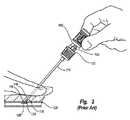
ここで図面、詳しくは図1〜図4を参照すると、先行技術による血管穿刺部閉鎖装置100が示される。血管穿刺閉鎖装置100は、フィラメントまたは縫合糸104がキャリアチューブ102の中を少なくとも部分的に通って延びる、キャリアチューブ102を備えている。閉鎖装置100は第1端部すなわち基端部106と第2端部すなわち先端部107とをさらに備えている。キャリアチューブ102の第2端部すなわち先端部107の外部には、アンカー108が存在する。アンカー108は、中間に針穴109が形成された、長尺で堅くて小断面積の部材である。アンカー108は、通常、生体が吸収性ポリマーで形成されている。 Referring now to the drawings, and more particularly to FIGS. 1-4, a prior art vascular
縫合糸104は、アンカー108を通され、コラーゲンパッド110に戻る。コラーゲンパッド110は、化学的手段によって一つに結合されたランダムに配向させられた繊維材料より構成され得る。縫合糸104が先端方向にキャリアチューブ102の中を通過するように、コラーゲンパッド110は摺動可能に縫合糸104に取り付けられているが、縫合糸104がアンカー108を横断してキャリアチューブ102に再び入るように、縫合糸104はコラーゲンパッド110より基端側でしっかりと引き結ばれ、これにより閉鎖装置100が適切に配置されてアンカー108が配置された場合(図4を参照)のコラーゲンパッド110の締付が促進される。 The
キャリアチューブ102の中には、通常、充填チューブ112が配置されている。充填チューブ112は、縫合糸104の上を摺動可能に装着され、経皮的組織穿刺部を封鎖するのに適した時に、アンカー108に向かってコラーゲンパッド110を充填する、すな
わち詰めるためにオペレータにより使用され得る。A filling
動脈内でのアンカー108の配置に先立って、アンカー108の針穴109は、キャリアチューブ102の先端部107の外側で静止する。アンカー108は、キャリアチューブ102の先端部107の上に配置されたバイパスチューブ114により、キャリアチューブ102と同じ高さ、すなわち面一に一時的に適所に保持され得る。 Prior to placement of the
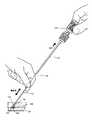
アンカー108およびキャリアチューブ102の面一の配置は、図2〜4に示されるように挿入シース116へのアンカー108の挿入、そして最終的にはアンカー108による動脈穿刺部118の通過を可能にする。図2〜4に示された挿入シース116は、経皮的切開部119を通過し、動脈128へ挿入される。しかしながら、バイパスチューブ114(図1)は、挿入シース116が内部を通過することによりバイパスチューブ114が通過するのを防ぐ、オーバーサイズヘッド120を備えている。従って、穿刺閉鎖装置100が挿入シース116に挿入されるとき、オーバーサイズヘッド120は挿入シース116の表面122に対し圧迫される。穿刺閉鎖装置100をさらに挿入すると、キャリアチューブ102(図1)とバイパスチューブ114との間に摺動が生じ、バイパスチューブ114(図1)からアンカー108が解放される。しかしながら、バイパスチューブ114からの解放後、アンカー108は、挿入シース116によって移動を制限され、図1に示される面一配置のままとなる。 The flush arrangement of
挿入シース116は、自身の第2端部すなわち先端部126に単一折り目124を備えている。単一折り目124はアンカー108にたいする一方向弁として作用する。単一折り目124は、アンカー108が挿入シース116の先端部126を通って押されるときに弾力的に屈曲する挿入シース116の部分の塑性変形である。通常、アンカー108が挿入シース116の先端部126を通過して動脈128に入った後、アンカー108はもはやキャリアチューブ102に対して面一配置に拘束されず、展開し、図2に示される位置へと回転する。 The
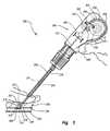
次に、アンカー108が配置されている図3〜4を参照すると、穿刺閉鎖装置100と挿入シース116は共に引き戻され、切開管119にコラーゲンパッド110が配置され、かつ充填チューブ112が露出している。図4に示されるように充填チューブ112が完全に露出された状態で、コラーゲンパッド110は手で詰められ、アンカー108とコラーゲンパッド110は共に締め付けられ、縫合糸104上の自己締付引き結び目によって適所に保持される。従って、組織穿刺部118はアンカー108とコラーゲンパッド110との間に挟まれるので、組織穿刺部118は封鎖される。その後、縫合糸104が切断され、穿刺部119が閉鎖され得る。縫合糸104、アンカー108およびコラーゲンパッド110は、一般に吸収性材料で形成されており、そのため穿刺部118が癒える間は定位置に残っている。 3-4, where the
しかしながら、上述の典型的な組織穿刺閉鎖装置100を使用すると、手で把持できるよう充填チューブ112を露出すべくシース116が除去されるまで、コラーゲンパッド110の充填を開始することができない。ある条件下では、コラーゲンパッド110の充填前にシース116を除去すると、コラーゲンパッド110が組織穿刺部118から引き戻され、コラーゲンパッド110と穿刺部118との間にギャップ120が生じる。図4に示されるように充填後でさえ、ギャップ120が残り、封鎖が部分的のみとなり、組織穿刺部118から出血が生じる場合がある。 However, using the typical tissue
従って、本明細書は、少なくとも部分的に巻かれる充填チューブを備えた組織穿刺閉鎖装置について説明する。かかる装置は、組織穿刺部位から組織穿刺閉鎖装置が引き戻されると、封鎖プラグ(例えばコラーゲンパッド110)を自動的に組織穿刺部に向かって駆
動し得る。組織穿刺閉鎖装置の好ましい実施形態を以下に図示し説明するが、本明細書の原理は任意の多くの組織閉鎖装置に組み込むことが可能である。以下に説明する特定の実施形態はあくまで例示を目的としており、限定的なものではない。The present description thus describes a tissue puncture closure device comprising a filling tube that is at least partially wound. Such a device can automatically drive a sealing plug (eg, collagen pad 110) toward the tissue puncture when the tissue puncture closure device is pulled back from the tissue puncture site. Although a preferred embodiment of a tissue puncture closure device is illustrated and described below, the principles herein can be incorporated into any number of tissue closure devices. The specific embodiments described below are for illustrative purposes only and are not limiting.
上述したように、皮膚の切開部を通じてアクセス可能な内部組織壁における組織穿刺部の封鎖のために使用される組織閉鎖装置の一般構造と機能は、当該技術分野において周知である。本明細書で説明する原理を実施する閉鎖装置を含む、閉鎖装置の用途は、生体の2つの内部部分を分離する組織中の経皮的穿刺部または切開部、例えば血管、導管または管腔、胆嚢、肝臓、心臓等における経皮的穿刺部または切開閉鎖部の閉鎖を包含する。 As noted above, the general structure and function of a tissue closure device used to seal a tissue puncture in an internal tissue wall accessible through a skin incision is well known in the art. Applications of closure devices, including closure devices that implement the principles described herein, include percutaneous punctures or incisions in tissue that separate two internal parts of a living body, such as blood vessels, conduits or lumens, Includes percutaneous puncture or incision closure in the gallbladder, liver, heart, etc.
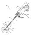
ここで図5を参照すると、本発明の1実施形態により、医療装置、例えば組織穿刺閉鎖装置200が示される。閉鎖装置200は、血管(例えば動脈)穿刺の止血を即時に引き起こすように設計されているため、血管造影法の染料注入、心臓カテーテル法、バルーン血管形成術および他の種類のアテローム性動脈硬化の動脈の再開等に関して使用される場合に、閉鎖装置200は特に有用性を有する。しかしながら、以下の好ましい実施形態の説明は、動脈における経皮的穿刺部を封鎖することに関するが、そのような装置はもっと多くの用途を有し、他の種類の組織壁の穿刺部や切開部を封鎖するのにも使用可能である。従って、ここに示す動脈における経皮的穿刺部の封鎖は、本発明の組織閉鎖装置200の1つの特定の使用方法の例示にすぎない。 Referring now to FIG. 5, a medical device, such as a tissue
組織閉鎖装置200は第1端部すなわち基端部206と、第2端部すなわち先端部207とを備えている。キャリアチューブ202は基端部206から先端部207まで延び、先端部207に出口213を備えている。キャリアチューブ202はプラスチックまたは他の材料から形成されており、シース216の中に挿入されるよう設計されている。シース216は、挿入されて、組織層230の中の経皮切開部219を通過し、管腔232に入るよう設計されている。図5によれば、管腔232は大腿動脈228の内部部分からなる。 The
キャリアチューブ202の先端部207には、アンカー208と封鎖プラグ210が存在する。好ましい実施形態のアンカー208は、穿刺部218に隣接する動脈壁234に接触して動脈228の内部に着座するよう配置された、長尺で堅くて小断面積の部材である。アンカー208は、好ましくは生体吸収性ポリマーから形成される。封鎖プラグ210は、コラーゲン等のやはり非止血性の生体吸収性材料から形成された圧縮可能なスポンジ、発泡体、または繊維状マットから形成され、組織穿刺部218の封鎖を促進するよう任意の形状に構成される。 An
封鎖プラグ210とアンカー208は、さらに生体吸収性フィラメントまたは縫合糸204により互いに接続される。アンカー208、封鎖プラグ210および縫合糸204は、以下、包括的に「閉鎖要素」と称する。図5に示されるように、アンカー208はシース216の先端部207に隣接してその外部に配置され、一方、封鎖プラグ210は初めはキャリアチューブ202の中に配置されえいる。第1の表面236が動脈壁234に接触した状態でアンカー208が示されているが、管腔232への挿入を促進するために、アンカーは最初はキャリアチューブ202に沿って軸方向に配列されていることが理解されるだろう(例えば図1のアンカー108参照)。縫合糸204は、閉鎖装置200の第1端部206からキャリアチューブ202の中を通って先端方向へ延びている。縫合糸204は、封鎖プラグ210中の1または複数の穿孔を通過し、アンカー208における孔を通過し、キャリアチューブ202に向かって封鎖プラグ210へと基端側に戻る。縫合糸204は好ましくは、封鎖プラグ210中の一つの穿孔または一連の複数の穿孔を通って再び縫合される。縫合糸204は、自己締付け引き結び目を形成するために、自身の周囲に糸を通されてもよい。このように縫合糸204は、キャリアチューブ202がアンカ
ー208および封鎖プラグ210から引き離された場合にアンカー208と封鎖プラグ210を一緒に締め付けるようにアンカー208と封鎖プラグ210をプーリーのような配置で接続し、アンカー208とプラグ210を共に挟んで固定し、それにより組織穿刺部218を封鎖する。
キャリアチューブ202はさらに充填装置を収容しており、充填装置は、例えば図5に示される、縫合糸204に沿ってアンカー208に向かって封鎖プラグ210を進めるために部分的に巻回された充填装置212である。充填装置212は、ハンドル252内で部分的に巻回された第1の部分242と、封鎖プラグ210に向かって先端側に延びる第2の部分244とを備えた状態で示されている。第1の部分242はスプールに巻回されるか、ガイド240,241(図12)の間に配置され得る。第1の部分242はシェーパ246よりも基端側の充填装置212の可変長さを有し、第2の部分244は、シェーパ246よりも先端側の充填装置212の可変長さを有する。シェーパ246については図12を参照しながら以下により詳細に示すが、断面積を変更してもよく、および/または、充填装置212のいくつかの実施形態がシェーパ246内を通過する時に該充填装置212の特定の軸に沿った曲げモーメントを増加させてもよい。従って、充填装置212の第1の部分242は一般に可撓性であり、少なくとも1つの方向へ巻くことができるが、第2の部分244は一般に堅くて直線状である。The
充填装置212は、第1の部分242を巻回すると共に第2の部分244を直線状かつ堅くする構成であれば、いかなる数の構成をも含む。第1の部分242は、充填装置212の一定の長さを非線形のコイル状に格納することにより、閉鎖装置200の圧縮を促進する。第2の部分244は、アンカー208の方向への封鎖プラグ210の前進または充填を促進する。充填装置212の異なる構成のいくつかの例については、図6A〜10Bに関して図示し、以下に説明する。 The filling
図6A〜6Bを参照すると、本発明の原理による充填装置212の1実施形態が示される。図6Aは図5のA−A線における充填装置212の断面図であるが、図6Aによれば、充填装置の第1の部分242は概ね開いた平坦な断面を含む。充填装置212の第1の部分242の概ね平坦な断面は、充填装置212のX軸の周囲で一般に低い曲げモーメン
トを有し、従って、X軸の周囲で可撓性を提供する。図6Aに示される充填装置212は、構造を弱める一対の切欠251を有し、かかる切欠251は異なる断面形状へと充填装置を折り畳むすなわち折り曲げるのを促進する。6A-6B, one embodiment of a
図6A〜6Bの実施形態によれば、充填装置212の第1の部分242が静止シェーパ246(図5)を通過すると、第1の部分242は折り畳まれ、図6Bに示されるように異なる断面を形成する。図6Bは、図5のB−B線における充填装置212の断面図を表わしている。従って、図6Bは、充填装置212の第2の部分244の断面を表わしている。図6Bに示されるように、充填装置212は折り畳まれると、溝、略U字形状、または略V字形状を形成する。従って、シェーパ246(図5)は、溝を形成する複数のくさび状の表面を備え得る。充填装置212の第2の部分244に形成された溝形は、第1の部分242の平坦な形状(図6A)と比較して、X軸の周囲ではるかに高い曲げモーメントを有し、従ってはるかに堅く、剛性があり、直線状である。従って、充填装置の第2の部分244は、アンカー208(図5)に向かって封鎖プラグ210(図5)を支持し、充填するのに十分に適している。図6A〜6Bに示されるような可撓な形状と堅くて曲がらない形状との間での充填装置の折り畳みは、十分な長さの充填装置212が閉鎖装置200のハンドル252内で巻かれることによりコンパクトな閉鎖装置200を促進すると共に、封鎖プラグ210(図5)の位置では充填装置212にさらに適切な剛性を提供する。According to the embodiment of FIGS. 6A-6B, when the
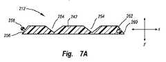
充填装置212の別の実施形態が、図7A〜7Bに断面図で示されている。図6Aに示した形状と同様に、図7Aの実施形態は、充填装置212の第1の部分242の図5のA−A線における断面図を示している。第1の部分242は概ね開いた可撓性で平坦な形状に配置されており、これは第1の部分242が好都合には巻かれることを可能にする。しかしながら、図7A〜7Bの充填装置212は、充填装置212を閉じた多角形の形に折り畳むことを促進する2つ以上の切欠254を有している。さらに、折り畳まれた時に充填装置212にバネ錠の形状を提供するに、充填装置212の第1端256が突出部258を備え、第2端260がそれに対合する穴262を備えてもよい。例えば、図7Bは、図5のB−B線における充填装置212の第2の部分244の断面図であるが、図7Bに示されるように、充填装置212の第2の部分244はシェーパ246(図5)により三角形の形状に折り畳まれてもよい。図6Bの溝の形状のように、図7Bの三角形の形状は図7Aの平坦な形状よりX軸の周囲ではるかに高い曲げモーメントを有しており、従って、その長手方向軸250に交差する方向に関し図7Aの平坦な形状よりはるかに堅い。本開示の恩恵を享受する当業者には、シェーパ246(図5)により、概ね平坦な形状から他の閉じた多角形も形成されるのであって、三角形は単なる例示であることが理解されよう。シェーパ246(図5)は、充填装置212がシェーパ246内を通過したときに充填装置212を任意の望ましい形状に折り畳むよう、種々のくさび状部材または表面を備え得る。Another embodiment of the
他の実施形態も同様に使用され得る。例えば、図8A〜8Bの実施形態は、可撓性配置と剛性配置との間で折り畳み可能な充填装置212のための別の形状を示している。図8Aは、図5の第1の部分242の平面図を示し、概ね平坦であるため巻くことが可能であり、充填装置212を堅くすると共に縁での滑りを防ぐために折り畳まれた時に係合する歯の付いた縁を備えている。シェーパ246(図5)によって折り畳まれた後、歯の付いた縁は係合し、図8Bに示される三角形のような閉じた多角形の断面を形成する。図8Bは図5のB−B線における充填装置212の第2の部分244を示している。 Other embodiments may be used as well. For example, the embodiment of FIGS. 8A-8B shows another shape for a
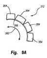
しかしながら、図5に示される充填装置212の断面を変更するシェーパ246を使用する代わりに、充填装置212のいくつかの実施形態は、折り畳まずに、すなわち断面の変更なしで、1つの方向へ巻回すると共に、他の方向へは剛性とし得る。従って、閉鎖装置200のいくつかの実施形態はシェーパ246を備えない場合がある。例えば、図9A〜9Bに示されるように、充填装置は鎖312を備えてもよい。図9A〜9Bは、断面図ではなく側面図で鎖312を示している。鎖312は、図9Aに弧状矢印360で表わされる第1の方向には可撓性であるが、図9Bに第2の弧状矢印362で表わされる第2の方向を含む他の方向には剛性である。 However, instead of using the
図9A〜9Bに示される鎖312は、共に可撓的に結合した複数のブロック364を備えている。各ブロック364は可撓性部材366により1つの角で隣接ブロックに接続される。可撓性部材366はプラスチックシートまたは容易に曲げられる他の材料からなり得る。図9A〜9Bに示されるように、鎖312は、ハンドル252(図5)内で第1の方向360へ巻回されるが、ブロック364は他の方向への巻回を防止するために互いに接触し、干渉し得る。さらに、鎖312は可撓性部材366によって第2の方向へよって偏倚され、その結果、鎖312が解かれると、鎖312は図9Bに示されるように直線で剛性の形状を形成する傾向がある。図9Bの直線で剛性の形は、封鎖プラグ210(図5)を縫合糸204(図5)に沿ってアンカー208(図5)に向かってを進めるための有効な充填装置を提供する。 The
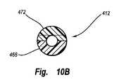
さらに、別の実施形態によれば、充填装置412(図10A〜10B)は多数の構成要素を備えてもよい。図10A〜10Bに示されるように、充填装置412は少なくとも部分的に巻回された第1の長手方向に延びる部分468と、少なくとも部分的に巻回された
第2の長手方向に延びる部分472とを備えている。第1の長手方向に延びる部分468は第1のスプール470上に部分的に巻かれ、第2の長手方向に延びる部分472は第2のスプール474上に部分的に巻かれ得る。しかしながら、第1および第2の長手方向に延びる部分468,472は、図示された巻回された形状へ、第1および第2の外表面476,478により案内されてもよい。図10A〜10Bによれば、第1および第2の長手方向に延びる部分468,472は、図10Bに示されるような略円形の断面を形成するように共に統合または噛合される対合する充填装置412の半分である。いったん噛み合うと、第1および第2の長手方向に延びる部分468,472は、充填装置として十分に機能する略直線の堅いチューブを構成する。第2の長手方向に延びる部分472は主駆動歯車480により前進または後退させられ、第1の長手方向に延びる部分468は主駆動歯車480と好ましくは係合された従駆動歯車482により同時に前進または後退させられる。主駆動歯車480は、図11〜12に関して以下に説明するように縫合糸204(図5)により好ましくは駆動される。Furthermore, according to another embodiment, the filling device 412 (FIGS. 10A-10B) may comprise a number of components. As shown in FIGS. 10A-10B, the filling
ここで、図11を見ると、縫合糸204は充填装置212の第2部分244を通って延びるが、第2部分244に直接接続されない。従って、縫合糸204と充填装置212は互いに自由に摺動して通過する。図11〜12に示した実施形態によれば、縫合糸204がハンドル252内を延びるとともに、縫合糸はハンドル252内に収容された自動解放機構530に取り付けられている。 Referring now to FIG. 11, the
実際には、(上述の閉鎖要素を収容する)閉鎖装置200のキャリアチューブ202が、動脈壁228の中に既に挿入されている挿入シース216に挿入される。閉鎖装置200および関連する閉鎖要素が挿入シース216に挿入されると、アンカー208は、挿入シース216の先端部207を通過し、先端部207から出て、動脈管腔232に挿入される。上述したように、アンカー208は、経皮的切り込み219を介した管腔232内へのアンカー208の挿入を促進すべく、初めはキャリアチューブ202とほぼ平行に配置されている。アンカー208が挿入シース216を通過して挿入シース216の外に出て管腔232の中へ入ると、アンカー208は図11に示される位置に回転する。 In practice, the
図11に示されるように管腔232内でアンカー208が横方向に回転した状態で、閉鎖装置200と挿入シース216は共に引き戻され、その結果アンカー208の表面236が動脈壁234に抗して接触する。閉鎖装置200と挿入シース216をさらに引き戻すと、封鎖プラグ210がキャリアチューブ202の先端部207から引き戻され、それにより切り込みまたは穿刺管219内にプラグ210が配置される。 With the
しかしながら、封鎖プラグ210の配置後に別の手動による充填処置を必要とする以前の閉鎖装置とは異なり、本発明の閉鎖装置200は部分的に巻回された充填装置212を用いて封鎖プラグ210を自動的に充填し得る。 However, unlike previous closure devices that require another manual filling procedure after placement of the
穿刺管219から閉鎖装置200が引き戻されると自動的に、閉鎖装置200は解けて封鎖プラグ210に向かって充填装置212を駆動し、図11に示されるようにアンカー208に向かって封鎖プラグ210を充填する。従って、キャリアチューブ216が大腿動脈228内の穿刺部218に隣接していまだ配置されている間に、封鎖プラグ210は充填され、封鎖プラグ210と動脈壁228の穿刺部218との間に生じ得るギャップが縮小または排除される。 When the
さらに、穿刺管219から離れるように縫合糸204に張力をかけるか縫合糸204を引っ張ることにより、縫合糸204は(引き結び目やそれと同等なもので)アンカー208と封鎖プラグ210を共に締め付けて固定し、アンカー208と封鎖プラグ210の間に動脈壁228を挟む。また、充填装置212によりかけられる力と、フィラメント20
4によるアンカー208と封鎖プラグ210との締め付けにより、封鎖プラグ210は穿刺管219内で径方向外側に向かって変形し、組織穿刺部218の基端側のアンカーとして機能する。Further, by applying tension to the
By tightening the
封鎖プラグ210の方向への充填装置212の自動的解放(および充填装置212の巻回された形によっては成形)と、および/または封鎖プラグ210とアンカー208の締め付けとは、任意の多くの機構によって促進され得る。例えば、図12には、閉鎖装置200のハンドル252に配置され得る自動解放機構530が示されている。図12の実施形態によれば、閉鎖装置200の引き戻しによって、封鎖プラグ210(図11)の充填は自動的に達成される。穿刺部218(図11)から閉鎖装置200を引き戻すのに必要な力の部分は、自動解放機構530によって反対の駆動力に自動的に変換される。 The automatic release of the
図12(および同様に図10A)の自動解放機構530によれば、縫合糸204は縫合糸スプール532(または図10Aの主駆動歯車480)に接続され、縫合糸スプール532の周囲に巻回される。組織穿刺部位(アンカー208(図11)が配置されている場合)から閉鎖装置200(図11)を引き戻すことにより、縫合糸204が縫合スプール532から解ける。縫合糸204が解けると縫合スプール532が回転し、充填装置212への駆動力または解放力に変換され得るねじれの駆動力を提供する。 According to the
図12の実施形態によれば、スプール532によって提供されるねじれの駆動力は、歯車列534により、充填装置212用の駆動力に変換される。歯車列534は、縫合スプール532と同軸に配置された第1の歯車536を備えている。第1の歯車536とスプール532はそれぞれ対合するファン表面538,540を有し得る。対合するファン表面538,540は、所定のレベルを超えるスプール532から第1の歯車536への例外的なねじれ力の伝達を防止するトルクを制限するクラッチを形成する。 According to the embodiment of FIG. 12, the torsional driving force provided by the
第1の歯車536と縫合スプール532の対合するファン表面538,540は、圧縮可能なワッシャ550等の偏倚部材により、回転軸線552の周囲の相互回転を許容しつつファン歯車表面538,540の機械的摩擦係合を引き起こすのに十分な力で、係合状態にされ得る。ねじれ力が所定レベルに達するかそれを超えた場合に限ってファン表面538,540の間の滑りが許容されるように、好ましくは、ファン表面538、540はシヌソイド形に形成される。しかしながら、V字形、正方形、および平面を含むがこれらに限られないその他のファン表面の形状も使用可能である。ファン表面538,540の機械的摩擦係合に打ち勝つのに必要なねじれ力のレベルは、シヌソイド形のファン面の周波数または振幅を調節することにより、ファン表面538,540の間の偏倚力を調節することにより、または他の方法により修正可能である。 The fan surfaces 538 and 540 where the
図12に示されるように、第1の歯車536は第2の歯車542と係合し得る。第1および第2の歯車536,542は、摩擦係合または歯車の歯により互いに係合し得る。第2の歯車542は第2歯車542とローラガイド546との間に配置された充填装置212にも係合すると共に、同充填装置212を解放する。スプール532が回転すると、第2歯車542はシェーパ246によって、初めは巻かれていた充填装置212の第1の部分242を駆動する。しかしながら、シェーパ246は第2歯車542の下流に配置されてもよい。シェーパ246は、充填装置212/312/412の特定の実施形態を新たなより堅くて曲がらない形状に折り畳むか、充填装置212/312/412に直線状にするか、および/または多数の充填装置構成要素が単一片へ噛み合うのを支援する。第2の歯車542はさらに封鎖プラグ210に向かって充填装置212を駆動し(図11)、従って封鎖プラグ210をアンカー208に向かって進める(図11)。本開示の恩恵を享受する当業者には、シェーパ246(図5)が図5では第2歯車542等の歯車の先端側に示されているが、歯車の基端側に位置してもよいことが理解されよう。 As shown in FIG. 12, the
閉鎖装置200が引き戻される直線速度に対して充填装置212の直線速度を増加させることが望ましい場合がある。充填装置212の直線速度の増加は、閉鎖装置200が穿刺部218から引き戻された場合(図11)に、封鎖プラグ210(図11)がアンカー208(図11)に向かって押されるのをよりよく保証する。従って、いくつかの実施形態によれば、歯車列534は1:1より大きい全体の歯数比を有してよく、追加の歯車を有してよい。例えば、歯数比は約2.5:1から6.0:1の間に及んでも良く、いくつかの実施形態によれば歯数比は約5.0:1である。 It may be desirable to increase the linear speed of the
しかしながら、過度の速度は潜在的に封鎖プラグ210(図11)を組織穿刺部218(図11)を通って管腔232(図11)へと押しやる可能性があるため、充填装置の直線速度は閉鎖装置の直線引き戻し速度よりも過度に大きくあるべきではない。同様に、アンカー208(図11)に対する反対方向の力が不十分な場合も潜在的に、管腔232(図11)の内部からアンカー208(図11)が引き出される可能性がある。従って、いくつかの用途によれば、引き戻し力は約1.6kg(約3.5ポンド)を超えるべきではない。 However, since excessive speed can potentially push the sealing plug 210 (FIG. 11) through the tissue puncture 218 (FIG. 11) and into the lumen 232 (FIG. 11), the linear speed of the filling device is Should not be excessively greater than the linear pullback speed of the closure device. Similarly, anchor 208 (FIG. 11) can potentially be pulled out of the interior of lumen 232 (FIG. 11) if the opposing force on anchor 208 (FIG. 11) is insufficient. Thus, according to some applications, the pull back force should not exceed about 1.6 kg (about 3.5 pounds).
本開示の恩恵を享受する当業者には、図10Aおよび12に示される駆動スプール/歯車列の形状が、本質的に例示であって、限定ではないことが理解されよう。自動駆動力を封鎖プラグ210(図11)に提供するために、閉鎖装置200(図11)の引き戻しにより生成された駆動力を伝達する歯車形状であれば、いかなるものが使用されてもよい。さらに、トルクを制限するクラッチは、歯車列534に沿ったどの時点に配置されてもよく、縫合糸スプール532と第1の歯車536との間の係合に限定されない。 Those skilled in the art having the benefit of this disclosure will appreciate that the shape of the drive spool / gear train shown in FIGS. 10A and 12 is exemplary in nature and not limiting. Any gear shape that transmits the driving force generated by the withdrawal of the closure device 200 (FIG. 11) may be used to provide automatic driving force to the sealing plug 210 (FIG. 11). Further, the torque limiting clutch may be located at any point along the
図11〜12の閉鎖装置200の動作は以下の通りである。閉鎖装置200が穿刺管219から引き戻されると、ハンドル252とアンカー208の間の分離力により、アンカー208の中に通されている縫合糸204はスプール532からほどけ、スプール532を回転させる。スプール532は、ファン表面538,540間の噛合係合を介して回転すると、第1の歯車536を駆動する。第1の歯車536が回転すると、第2の歯車542を駆動し、第2の歯車542は充填装置212を駆動する。充填装置212はシェーパ246の中を通過し、そこで堅くて直線状の形状に配置される。充填装置212は、封鎖プラグ210に向かって延び、封鎖プラグ210を充填する。従って、閉鎖装置200が穿刺管219から引き戻されると、封鎖プラグ210が自動駆動機構530によって自動的に充填される。従って、封鎖プラグ210は封鎖プラグ210とアンカー208の間にギャップのない十分な動脈封鎖を形成する。かかるギャップは、そうでない場合、別個の手動による充填処置で生じ得るものである。 The operation of the
上記に図示され、説明された実施形態は、閉鎖器具200の引き戻しに関連する力を封鎖プラグ210にかかる自動充填力へ変換するために使用可能な機械的変換器を示しているが、封鎖プラグ210の自動充填を促すために本発明の原理に従って他の変換器が使用されてもよい。第1の方向の駆動力を別の方向の後続の力へと変換するためなら、任意の手段を使用可能である。例えば、図13を参照すると、閉鎖ツール200を穿刺管から引き戻す際に自動充填力を生成するために、電気スイッチおよび/または光学変換器が使用され得る。従って、電気スイッチおよび/または光学センサ660は、閉鎖装置200の引き戻しを示す信号を、通信インタフェース662に沿って、モータ、サーボ、ソレノイドまたは他の装置664に送信し得る。その後、引き戻し信号を受け取ると、モータ、サーボ、ソレノイドまたは他の装置664は充填力を提供し得る。 Although the embodiment shown and described above shows a mechanical transducer that can be used to convert the force associated with the withdrawal of the
従って、いくつかの実施形態によれば、縫合糸204の基端部は、電子スイッチ660と作用的に接続され、電子スイッチ660はモータ664(または電源)に作用的に接続
される。閉鎖装置200の引き戻しにより電子スイッチ660は作動すると共にモータ664が駆動され、充填装置212をほどき、封鎖プラグ210を充填するために使用される力が生成される。同様に、電子スイッチ660は、組織の穿刺から閉鎖装置200の引き戻しを検知および/または測定し、組織の穿刺から閉鎖装置の引き戻しを示す信号を生成する光学センサであるか、そのような光学センサを備えてもよい。光学信号は電気信号に変換され、電気信号は封鎖プラグ210に対する駆動力または充填力を生成すべくモータ664(または電源)に送信され得る。モータ、サーボ、ソレノイドまたは他の装置664は、(上述に類似の方法で直線の駆動力に変換される)ねじれ力を生成するよう回転式であってよいが、または、モータ、サーボ、ソレノイドまたは他の装置664は、充填装置212に直接または間接的に加えられる力を生成するよう線形であってもよい。Thus, according to some embodiments, the proximal end of
上述の組織閉鎖装置200は、血管形成術またはカテーテル法等の血管内処置の後で特に有用であり得る。従って、かかる処置のために取られ得る一般的な工程を以下に説明するが、かかる工程には組織閉鎖装置200を使用する前にいくつかの方法によって取られ得る多数の工程が続き得る。 The
標準的な血管内処置によれば、血管造影法の針等の器具のカニューレが、皮膚を介して動脈(例えば大腿動脈)内の器具挿入用の位置に挿入される。血管造影法の針は適所に保持され、可撓性ガイドワイヤが、それが所望の深さに達するまで針を通じて動脈内へ長手方向に通過される。一旦ガイドワイヤが適所に配置されると、血管造影法の針はガイドワイヤを適所に残して除去される。処置シースおよび動脈拡張器がガイドワイヤ上に沿って、穿刺部または切開部を通って、動脈内へと通過させられる。ガイドワイヤおよびその後拡張器は、処置シースを適所に残して除去される。その後、カテーテルまたは他の血管内器具が処置シースおよび動脈を通過して所望の血管内位置(例えばアテローム性動脈硬化の閉塞位置)まで挿入される。血管内処置(例えば血管形成術)が終了すると、カテーテルは処置シースを適所に残して除去される。 According to standard endovascular procedures, a cannula of an instrument such as an angiographic needle is inserted through the skin into a position for instrument insertion in an artery (eg, a femoral artery). The angiographic needle is held in place and a flexible guidewire is passed longitudinally through the needle and into the artery until it reaches the desired depth. Once the guidewire is in place, the angiographic needle is removed leaving the guidewire in place. The treatment sheath and arterial dilator are passed over the guidewire, through the puncture or incision and into the artery. The guide wire and then the dilator are removed leaving the treatment sheath in place. A catheter or other intravascular device is then inserted through the treatment sheath and artery to the desired intravascular location (eg, atherosclerotic occlusion location). When the endovascular procedure (eg, angioplasty) is complete, the catheter is removed leaving the treatment sheath in place.
その後、処置シースは閉鎖装置200の導入を促進するために使用され得る。まず、動脈の位置決定を支援するために別のガイドワイヤが使用される。その後、ガイドワイヤを適所に残して処置シースが除去される。その後、挿入シース216および拡張器が、ガイドワイヤに沿って、経皮的切開部および組織穿刺部を通じて、動脈へと挿入される。ガイドワイヤと拡張器は除去され、挿入シース216は適所に残され、上述したように組織閉鎖装置200による組織穿刺へのアクセスのために使用される。 Thereafter, the treatment sheath can be used to facilitate the introduction of the
上記の説明は本発明の例証的実施形態を図示および説明するために提示したにすぎず、網羅的なものではなく、発明を開示した正確な形式に限定することを意図しない。上記の教示に照らして多くの改変および変更が可能なのであって、本発明の範囲は特許請求の範囲によって定義されるものとする。 The foregoing description has been presented only to illustrate and describe illustrative embodiments of the invention and is not exhaustive and is not intended to limit the invention to the precise form disclosed. Many modifications and variations are possible in light of the above teaching, and the scope of the present invention is defined by the appended claims.
Claims (16)
Translated fromJapanese組織の管の中で配置されるよう構成された封鎖プラグ;
少なくとも部分的に巻かれ、組織の管内に封鎖プラグを充填すべく巻回された形状と解かれた形状との間で移動するよう構成された、充填装置;および
シェーパ;を備え、
充填装置は巻回部分と解かれた部分とを備え、解かれた部分は組織の管内に封鎖プラグを充填すべく構成され、解かれた部分は巻回部分とは異なる断面形状を有し、
シェーパより基端側の充填装置の巻回部分の断面はほぼ平坦であり、シェーパは、充填装置がシェーパの中を先端側に進むと充填装置の該巻回部分を堅くて曲がらない形状に折り畳む、組織穿刺閉鎖装置。A tissue puncture closure device,
A sealing plug configured to be placed in a tissue tube;
Partially wound even withoutlow, configured to move betweena tissue tract sealing plug was solved and the wound shape in order to fill the shape, the fillingdevice; and
A shaper;
The filling device comprises a wound portion and an unraveled portion, the unraveled portion is configured to fill a sealing plug into a tissue tube, the unraveled portion having a different cross-sectional shape than the wound portion;
The cross section of the winding portion of the filling device on the proximal side from the shaper is substantially flat, and the shaper folds the winding portion of the filling device into a rigid and non-bending shape as the filling device advances through the shaper to the distal side. , tissue puncture closure device.
組織の管の中で配置されるよう構成された封鎖プラグ;
少なくとも部分的に巻かれ、組織の管内に封鎖プラグを充填すべく巻回された形状と解かれた形状との間で移動するよう構成された、充填装置;および
シェーパ;を備え、
充填装置は巻回部分と解かれた部分とを備え、解かれた部分は組織の管内に封鎖プラグ
を充填すべく構成され、解かれた部分は巻回部分とは異なる断面形状を有し、
充填装置は、少なくとも部分的に巻回された長手方向に延びる第1の部分と、少なくとも部分的に巻回された長手方向に延びる第2の部分とを有し、前記解かれた部分は、前記第1の部分と前記第2の部分とが統合されてなり、
シェーパが、前記第1の部分と、前記第2の部分とを、堅い略直線部材へと統合する、組織穿刺閉鎖装置。A tissue puncture closure device,
A sealing plug configured to be placed in a tissue tube;
Partially wound even withoutlow, configured to move betweena tissue tract sealing plug was solved and the wound shape in order to fill the shape, the filling device;and
A shaper;
The filling device comprises a wound portion and an unraveled portion, the unraveled portion is configured to fill a sealing plug into a tissue tube, the unraveled portion having a different cross-sectional shape than the wound portion;
The filling device has a longitudinally extending first portion that is at least partially wound and a longitudinally extending second portion that is at least partially wound, the unraveled portion comprising: The first part and the second part are integrated,
A tissue puncture closure device, wherein a shaper integrates the first portion and the second portion into a rigid, generally linear member .
組織の管の中で配置されるよう構成された封鎖プラグ;および
少なくとも部分的に巻かれ、組織の管内に封鎖プラグを充填すべく巻回された形状と解かれた形状との間で移動するよう構成された、充填装置;を備え、
充填装置は巻回部分と解かれた部分とを備え、解かれた部分は組織の管内に封鎖プラグを充填すべく構成され、
充填装置は、各々が隣接ブロックに可撓的に結合された複数のブロックを備える鎖をさらに備え、前記鎖は、第1の方向には可撓性を有する一方、前記第1の方向と反対方向には、前記複数のブロックが互いに接触して干渉して該反対方向への巻回が防止されることによる剛性を有する、組織穿刺閉鎖装置。A tissue puncture closure device,
Sealing plug configured to be placed within the tissue of the tube; a wound and at least partially, to move betweenthe wound shape and solved shape in order to fill the sealing plug in the tube of tissue A filling device configured to comprise:
The filling device comprises a wound portion and an unraveled portion, the unraveled portion configured to fill a sealing plug into a tissue tube;
Filling apparatus further comprises a chain comprising a plurality of blocks each of which is flexibly coupled to the adjacent block, said chain, while in the first direction having flexibility, and the first direction In the opposite direction, the tissue puncture closure device has rigidity due to the plurality of blocks coming into contact with each other and interfering with each other to prevent winding in the opposite direction.
フィラメントの少なくとも一部が巻回されたフィラメントスプール;および
フィラメントスプールに噛合する歯車;
をさらに備える請求項1〜10のいずれか一項に記載の組織穿刺閉鎖装置。A filament coupled to the sealing plug, and an automatic release device for releasing the filling device in response to withdrawal of the tissue puncture closure device from the tissue tube, the automatic release device comprising:
A filament spool wound with at least a portion of the filament; and a gear meshing with the filament spool;
The tissue puncture closure device according to any one of claims 1 to10 , further comprising:
キャリアチューブ;および
組織穿刺閉鎖装置の第1端部におけるハンドル;をさらに備え、
充填装置の少なくとも一部が、ハンドル内で巻回されている請求項1〜12のいずれか一項に記載の組織穿刺閉鎖装置。An anchor configured to be positioned adjacent to a hole in the tissue wall;
A carrier tube; and a handle at the first end of the tissue puncture closure device;
The tissue puncture closure device according to any one of claims 1 to12 , wherein at least a part of the filling device is wound in a handle.
請求項1、6、および8のいずれか一項に記載の組織穿刺閉鎖装置。The driving force generated by pulling back thetissue puncture closure device in the first direction is converted into a filling force for the sealing plug, thereby releasing the filling device to fill the sealing plug toward the tissue puncture portion. The tissue puncture closure device according to any one of claims 1 to6 , and8 .
Applications Claiming Priority (3)
| Application Number | Priority Date | Filing Date | Title |
|---|---|---|---|
| US11/532,819 | 2006-09-18 | ||
| US11/532,819US7749248B2 (en) | 2006-09-18 | 2006-09-18 | Flexible tamping device |
| PCT/US2007/078735WO2008036634A1 (en) | 2006-09-18 | 2007-09-18 | Flexible tamping device |
Publications (2)
| Publication Number | Publication Date |
|---|---|
| JP2010503499A JP2010503499A (en) | 2010-02-04 |
| JP5438515B2true JP5438515B2 (en) | 2014-03-12 |
Family
ID=38806228
Family Applications (1)
| Application Number | Title | Priority Date | Filing Date |
|---|---|---|---|
| JP2009528525AActiveJP5438515B2 (en) | 2006-09-18 | 2007-09-18 | Flexible filling device |
Country Status (7)
| Country | Link |
|---|---|
| US (2) | US7749248B2 (en) |
| EP (1) | EP2068720B1 (en) |
| JP (1) | JP5438515B2 (en) |
| AU (1) | AU2007297384B2 (en) |
| CA (1) | CA2662972C (en) |
| CR (1) | CR10731A (en) |
| WO (1) | WO2008036634A1 (en) |
Families Citing this family (52)
| Publication number | Priority date | Publication date | Assignee | Title |
|---|---|---|---|---|
| US8961541B2 (en) | 2007-12-03 | 2015-02-24 | Cardio Vascular Technologies Inc. | Vascular closure devices, systems, and methods of use |
| US20080109030A1 (en) | 2001-04-24 | 2008-05-08 | Houser Russell A | Arteriotomy closure devices and techniques |
| US8992567B1 (en) | 2001-04-24 | 2015-03-31 | Cardiovascular Technologies Inc. | Compressible, deformable, or deflectable tissue closure devices and method of manufacture |
| US7749247B2 (en)* | 2005-08-04 | 2010-07-06 | St. Jude Medical Puerto Rico, Llc | Tissue puncture closure device with coiled automatic tamping system |
| JP5426553B2 (en) | 2007-09-12 | 2014-02-26 | トランスルミナル テクノロジーズ リミテッド ライアビリティー カンパニー | Closure device, placement device, and method of placing a closure device |
| US9456816B2 (en) | 2007-09-12 | 2016-10-04 | Transluminal Technologies, Llc | Closure device, deployment apparatus, and method of deploying a closure device |
| US8876861B2 (en)* | 2007-09-12 | 2014-11-04 | Transluminal Technologies, Inc. | Closure device, deployment apparatus, and method of deploying a closure device |
| US9364206B2 (en) | 2008-04-04 | 2016-06-14 | Access Closure, Inc. | Apparatus and methods for sealing a vascular puncture |
| US8029533B2 (en) | 2008-04-04 | 2011-10-04 | Accessclosure, Inc. | Apparatus and methods for sealing a vascular puncture |
| US9271706B2 (en)* | 2008-08-12 | 2016-03-01 | Covidien Lp | Medical device for wound closure and method of use |
| US9943302B2 (en) | 2008-08-12 | 2018-04-17 | Covidien Lp | Medical device for wound closure and method of use |
| US9314238B2 (en)* | 2008-11-03 | 2016-04-19 | Syntorr, Inc. | T-type suture anchor |
| US8375553B2 (en) | 2009-02-20 | 2013-02-19 | Boston Scientific Scimed, Inc. | Locking element for vascular closure device |
| US9913634B2 (en) | 2009-02-20 | 2018-03-13 | Boston Scientific Scimed, Inc. | Locking element for vascular closure device |
| US8317824B2 (en) | 2009-02-20 | 2012-11-27 | Boston Scientific Scimed, Inc. | Tissue puncture closure device |
| US8052914B2 (en) | 2009-02-20 | 2011-11-08 | Boston Scientific Scimed, Inc. | Modified plug for arteriotomy closure |
| US8529598B2 (en) | 2009-02-20 | 2013-09-10 | Boston Scientific Scimed, Inc. | Tissue puncture closure device |
| US8292918B2 (en) | 2009-02-20 | 2012-10-23 | Boston Scientific Scimed, Inc. | Composite plug for arteriotomy closure and method of use |
| EP2416711A4 (en) | 2009-04-09 | 2017-06-07 | Cardiovascular Technologies, Inc. | Tissue closure devices, device and systems for delivery, kits and methods therefor |
| WO2010129510A2 (en)* | 2009-05-04 | 2010-11-11 | Incept. Llc | Biomaterials for track and puncture closure |
| WO2010129042A1 (en) | 2009-05-05 | 2010-11-11 | St. Jude Medical Puerto Rico Llc | Tissue puncture closure device with actuatable automatic spool driven compaction system |
| EP2533698B1 (en) | 2010-02-11 | 2018-03-28 | Boston Scientific Scimed, Inc. | Automatic vascular closure deployment devices |
| WO2011146729A2 (en)* | 2010-05-19 | 2011-11-24 | Cook Incorporated | Devices and methods useful for sealing bodily openings |
| EP2605707B1 (en)* | 2010-08-20 | 2014-10-08 | St. Jude Medical Puerto Rico LLC | Clutch release mechanism for vascular closure device |
| US8597340B2 (en) | 2010-09-17 | 2013-12-03 | Boston Scientific Scimed, Inc. | Torque mechanism actuated bioabsorbable vascular closure device |
| US9149264B2 (en)* | 2010-10-08 | 2015-10-06 | St. Jude Medical Puerto Rico Llc | Cam driven compaction tube for vascular closure device |
| AU2011326525B2 (en) | 2010-11-09 | 2015-06-18 | Transluminal Technologies, Llc | Specially designed magnesium-aluminum alloys and medical uses thereof in a hemodynamic environment |
| US8758402B2 (en) | 2010-12-17 | 2014-06-24 | Boston Scientific Scimed, Inc. | Tissue puncture closure device |
| US8974476B2 (en) | 2011-03-23 | 2015-03-10 | St. Jude Medical Puerto Rico Llc | Vascular closure device with compaction tube suture cutting port and methods |
| US10485524B2 (en) | 2011-10-25 | 2019-11-26 | Essential Medical, Inc. | Instrument and methods for surgically closing percutaneous punctures |
| WO2013081905A1 (en)* | 2011-11-28 | 2013-06-06 | St. Jude Medical Puerto Rico Llc | Anchor device for large bore vascular closure |
| US9192375B2 (en) | 2012-02-29 | 2015-11-24 | Marker Medical, Llc | Surgical apparatus and method |
| US9757104B2 (en) | 2012-07-19 | 2017-09-12 | Essential Medical, Inc. | Multi-lumen tamper tube |
| US9307966B2 (en) | 2012-08-15 | 2016-04-12 | St. Jude Medical Puerto Rico Llc | Vascular closure device anchor |
| US9743920B2 (en)* | 2012-08-20 | 2017-08-29 | Terumo Puerto Rico, L.L.C. | Flexible tamping member |
| US9468429B2 (en) | 2012-08-21 | 2016-10-18 | St. Jude Medical Puerto Rico Llc | Sealing mechanism for closure devices |
| US9585643B2 (en)* | 2012-08-21 | 2017-03-07 | St. Jude Medical Puerto Rico Llc | Carrier tubes for closure devices |
| US9131932B2 (en)* | 2013-02-01 | 2015-09-15 | St. Jude Medical Puerto Rico Llc | Dual lumen carrier tube with retractable sleeve and methods |
| US9307967B2 (en) | 2013-03-08 | 2016-04-12 | St. Jude Medical Puerto Rico Llc | Linkage driven compaction device |
| US10639019B2 (en) | 2013-03-15 | 2020-05-05 | Arrow International, Inc. | Vascular closure devices and methods of use |
| US10154835B2 (en) | 2013-05-09 | 2018-12-18 | Essential Medical, Inc. | Vascular closure device with conforming plug member |
| EP2832316B1 (en)* | 2013-07-31 | 2017-03-29 | Venus MedTech (HangZhou), Inc. | Handle assembly for implant delivery apparatus comprising a displacement limiter, a force limiter and/or a brake frame assembly |
| EP2832318B1 (en)* | 2013-07-31 | 2017-04-05 | Venus MedTech (HangZhou), Inc. | Handle assembly for implant delivery apparatus comprising a force limiter, a displacement limiter and/or a brake frame assembly |
| EP2832315B1 (en)* | 2013-07-31 | 2017-11-22 | Venus MedTech (HangZhou), Inc. | Handle assembly for implant delivery apparatus comprising a brake frame assembly, a force limiter and/or a displacement limiter |
| EP3858254B1 (en) | 2013-12-23 | 2024-04-24 | Teleflex Life Sciences LLC | Vascular closure device |
| US10555727B2 (en) | 2015-06-26 | 2020-02-11 | Essential Medical, Inc. | Vascular closure device with removable guide member |
| JP7174886B2 (en)* | 2018-05-11 | 2022-11-18 | テレフレックス ライフ サイエンシズ リミテッド | Intraosseous space access device and method for accessing bone marrow |
| CN109247978B (en)* | 2018-11-02 | 2021-06-01 | 深圳市先健畅通医疗有限公司 | In-situ windowing instrument |
| CN110960285A (en)* | 2020-01-15 | 2020-04-07 | 付志刚 | Vascular sheath group with hemostasis function |
| US12390249B2 (en) | 2020-07-31 | 2025-08-19 | Teleflex Life Sciences Llc | Access sheath with valve assembly |
| US12383246B2 (en) | 2020-10-12 | 2025-08-12 | Abbott Cardiovascular Systems, Inc. | Vessel closure device with improved safety and tract hemostasis |
| CN115444484B (en)* | 2022-08-22 | 2025-04-18 | 四川行动医疗科技股份有限公司 | Driving mechanism for intracranial vascular opening plugging equipment |
Family Cites Families (121)
| Publication number | Priority date | Publication date | Assignee | Title |
|---|---|---|---|---|
| US4317445A (en) | 1980-03-31 | 1982-03-02 | Baxter Travenol Laboratories, Inc. | Catheter insertion unit with separate flashback indication for the cannula |
| USRE34866E (en) | 1987-02-17 | 1995-02-21 | Kensey Nash Corporation | Device for sealing percutaneous puncture in a vessel |
| US4852568A (en) | 1987-02-17 | 1989-08-01 | Kensey Nash Corporation | Method and apparatus for sealing an opening in tissue of a living being |
| US4890612A (en) | 1987-02-17 | 1990-01-02 | Kensey Nash Corporation | Device for sealing percutaneous puncture in a vessel |
| NL8901350A (en) | 1989-05-29 | 1990-12-17 | Wouter Matthijs Muijs Van De M | CLOSURE ASSEMBLY. |
| US6190400B1 (en) | 1991-10-22 | 2001-02-20 | Kensey Nash Corporation | Blood vessel sealing device and method of sealing an opening in a blood vessel |
| JP2528602B2 (en) | 1989-12-04 | 1996-08-28 | ケンゼー・ナッシュ・コーポレーション | Plug device for sealing the opening |
| US5061274A (en) | 1989-12-04 | 1991-10-29 | Kensey Nash Corporation | Plug device for sealing openings and method of use |
| US5021059A (en) | 1990-05-07 | 1991-06-04 | Kensey Nash Corporation | Plug device with pulley for sealing punctures in tissue and methods of use |
| US5391183A (en) | 1990-09-21 | 1995-02-21 | Datascope Investment Corp | Device and method sealing puncture wounds |
| US5108421A (en) | 1990-10-01 | 1992-04-28 | Quinton Instrument Company | Insertion assembly and method of inserting a vessel plug into the body of a patient |
| US5290310A (en) | 1991-10-30 | 1994-03-01 | Howmedica, Inc. | Hemostatic implant introducer |
| US5676689A (en) | 1991-11-08 | 1997-10-14 | Kensey Nash Corporation | Hemostatic puncture closure system including vessel location device and method of use |
| US5222974A (en) | 1991-11-08 | 1993-06-29 | Kensey Nash Corporation | Hemostatic puncture closure system and method of use |
| US5411520A (en) | 1991-11-08 | 1995-05-02 | Kensey Nash Corporation | Hemostatic vessel puncture closure system utilizing a plug located within the puncture tract spaced from the vessel, and method of use |
| US5282827A (en) | 1991-11-08 | 1994-02-01 | Kensey Nash Corporation | Hemostatic puncture closure system and method of use |
| US5403328A (en) | 1992-04-22 | 1995-04-04 | United States Surgical Corporation | Surgical apparatus and method for suturing body tissue |
| US6063085A (en) | 1992-04-23 | 2000-05-16 | Scimed Life Systems, Inc. | Apparatus and method for sealing vascular punctures |
| CA2134071C (en) | 1992-04-23 | 1999-04-27 | Sew Wah Tay | Apparatus and method for sealing vascular punctures |
| US5810810A (en) | 1992-04-23 | 1998-09-22 | Scimed Life Systems, Inc. | Apparatus and method for sealing vascular punctures |
| US5368601A (en) | 1992-04-30 | 1994-11-29 | Lasersurge, Inc. | Trocar wound closure device |
| US5326350A (en) | 1992-05-11 | 1994-07-05 | Li Shu Tung | Soft tissue closure systems |
| US5292332A (en) | 1992-07-27 | 1994-03-08 | Lee Benjamin I | Methods and device for percutanceous sealing of arterial puncture sites |
| US5443481A (en) | 1992-07-27 | 1995-08-22 | Lee; Benjamin I. | Methods and device for percutaneous sealing of arterial puncture sites |
| US5342393A (en) | 1992-08-27 | 1994-08-30 | Duke University | Method and device for vascular repair |
| CA2106127A1 (en) | 1992-09-23 | 1994-03-24 | Peter W.J. Hinchliffe | Instrument for closing trocar puncture wounds |
| US5306254A (en) | 1992-10-01 | 1994-04-26 | Kensey Nash Corporation | Vessel position locating device and method of use |
| US5383897A (en) | 1992-10-19 | 1995-01-24 | Shadyside Hospital | Method and apparatus for closing blood vessel punctures |
| US5304184A (en) | 1992-10-19 | 1994-04-19 | Indiana University Foundation | Apparatus and method for positive closure of an internal tissue membrane opening |
| US5417699A (en) | 1992-12-10 | 1995-05-23 | Perclose Incorporated | Device and method for the percutaneous suturing of a vascular puncture site |
| US5320639A (en) | 1993-03-12 | 1994-06-14 | Meadox Medicals, Inc. | Vascular plug delivery system |
| US5312435A (en) | 1993-05-17 | 1994-05-17 | Kensey Nash Corporation | Fail predictable, reinforced anchor for hemostatic puncture closure |
| US6017359A (en) | 1993-05-25 | 2000-01-25 | Vascular Solutions, Inc. | Vascular sealing apparatus |
| US5868778A (en) | 1995-10-27 | 1999-02-09 | Vascular Solutions, Inc. | Vascular sealing apparatus and method |
| WO1994028800A1 (en) | 1993-06-04 | 1994-12-22 | Kensey Nash Corporation | Hemostatic vessel puncture closure with filament lock |
| ATE141481T1 (en) | 1993-06-16 | 1996-09-15 | White Spot Ag | DEVICE FOR INTRODUCING FIBRIN GLUE INTO A STITCH CHANNEL |
| US5725551A (en) | 1993-07-26 | 1998-03-10 | Myers; Gene | Method and apparatus for arteriotomy closure |
| US5486195A (en) | 1993-07-26 | 1996-01-23 | Myers; Gene | Method and apparatus for arteriotomy closure |
| US5462561A (en) | 1993-08-05 | 1995-10-31 | Voda; Jan K. | Suture device |
| US5405354A (en) | 1993-08-06 | 1995-04-11 | Vance Products Inc. | Suture driver |
| US5431639A (en) | 1993-08-12 | 1995-07-11 | Boston Scientific Corporation | Treating wounds caused by medical procedures |
| US5827299A (en) | 1993-08-25 | 1998-10-27 | Inlet Medical, Inc | Insertable suture passing grasping probe and methodology for using same |
| NL9301526A (en) | 1993-09-03 | 1995-04-03 | Cordis Europ | Device for hemostasis treatment after catheter surgery. |
| US5653730A (en) | 1993-09-28 | 1997-08-05 | Hemodynamics, Inc. | Surface opening adhesive sealer |
| US5759194A (en) | 1993-09-28 | 1998-06-02 | Hemodynamics, Inc. | Vascular patch applicator |
| US5843124A (en) | 1993-09-28 | 1998-12-01 | Hemodynamics, Inc. | Surface opening adhesive sealer |
| US5383899A (en) | 1993-09-28 | 1995-01-24 | Hammerslag; Julius G. | Method of using a surface opening adhesive sealer |
| US5527322A (en) | 1993-11-08 | 1996-06-18 | Perclose, Inc. | Device and method for suturing of internal puncture sites |
| US5728122A (en) | 1994-01-18 | 1998-03-17 | Datascope Investment Corp. | Guide wire with releaseable barb anchor |
| US5431666A (en) | 1994-02-24 | 1995-07-11 | Lasersurge, Inc. | Surgical suture instrument |
| WO1995026683A1 (en) | 1994-03-31 | 1995-10-12 | Boston Scientific Corporation | Vascular plug with vessel locator |
| US5545178A (en)* | 1994-04-29 | 1996-08-13 | Kensey Nash Corporation | System for closing a percutaneous puncture formed by a trocar to prevent tissue at the puncture from herniating |
| US5531759A (en) | 1994-04-29 | 1996-07-02 | Kensey Nash Corporation | System for closing a percutaneous puncture formed by a trocar to prevent tissue at the puncture from herniating |
| WO1995032671A1 (en) | 1994-06-01 | 1995-12-07 | Perclose, Inc. | Method and device for providing vascular hemostasis |
| US6033401A (en) | 1997-03-12 | 2000-03-07 | Advanced Closure Systems, Inc. | Vascular sealing device with microwave antenna |
| DE4447557C2 (en) | 1994-08-18 | 1997-10-23 | Harren Ernst Diethelm | Puncture closure |
| US5549633A (en) | 1994-08-24 | 1996-08-27 | Kensey Nash Corporation | Apparatus and methods of use for preventing blood seepage at a percutaneous puncture site |
| US5496332A (en) | 1994-10-20 | 1996-03-05 | Cordis Corporation | Wound closure apparatus and method for its use |
| US5814062A (en)* | 1994-12-22 | 1998-09-29 | Target Therapeutics, Inc. | Implant delivery assembly with expandable coupling/decoupling mechanism |
| US5649959A (en) | 1995-02-10 | 1997-07-22 | Sherwood Medical Company | Assembly for sealing a puncture in a vessel |
| US5755727A (en) | 1995-06-02 | 1998-05-26 | Cardiologics L.L.C. | Method device for locating and sealing a blood vessel |
| US5902311A (en) | 1995-06-15 | 1999-05-11 | Perclose, Inc. | Low profile intraluminal suturing device and method |
| US5792173A (en) | 1995-07-10 | 1998-08-11 | Stuart D. Edwards | Wound closure hemostasis device |
| US5810846A (en) | 1995-08-03 | 1998-09-22 | United States Surgical Corporation | Vascular hole closure |
| WO1997007745A1 (en) | 1995-08-24 | 1997-03-06 | Nobles-Lai Engineering, Inc. | Method and apparatus for suturing |
| US6162192A (en) | 1998-05-01 | 2000-12-19 | Sub Q, Inc. | System and method for facilitating hemostasis of blood vessel punctures with absorbable sponge |
| US6071300A (en) | 1995-09-15 | 2000-06-06 | Sub-Q Inc. | Apparatus and method for percutaneous sealing of blood vessel punctures |
| US5645566A (en) | 1995-09-15 | 1997-07-08 | Sub Q Inc. | Apparatus and method for percutaneous sealing of blood vessel punctures |
| US5674231A (en) | 1995-10-20 | 1997-10-07 | United States Surgical Corporation | Apparatus and method for vascular hole closure |
| US5814065A (en) | 1996-02-09 | 1998-09-29 | Cordis Corporation | Suture delivery tool |
| US5728132A (en) | 1996-04-08 | 1998-03-17 | Tricardia, L.L.C. | Self-sealing vascular access device |
| US5662681A (en) | 1996-04-23 | 1997-09-02 | Kensey Nash Corporation | Self locking closure for sealing percutaneous punctures |
| US5855585A (en) | 1996-06-11 | 1999-01-05 | X-Site, L.L.C. | Device and method for suturing blood vessels and the like |
| US5728133A (en) | 1996-07-09 | 1998-03-17 | Cardiologics, L.L.C. | Anchoring device and method for sealing percutaneous punctures in vessels |
| US5820631A (en) | 1996-08-01 | 1998-10-13 | Nr Medical, Inc. | Device and method for suturing tissue adjacent to a blood vessel |
| US5810884A (en) | 1996-09-09 | 1998-09-22 | Beth Israel Deaconess Medical Center | Apparatus and method for closing a vascular perforation after percutaneous puncture of a blood vessel in a living subject |
| US5728134A (en) | 1996-09-17 | 1998-03-17 | Barak; Shlomo | Method and apparatus for hemostasis |
| US5766183A (en) | 1996-10-21 | 1998-06-16 | Lasersurge, Inc. | Vascular hole closure |
| US6036721A (en) | 1996-11-16 | 2000-03-14 | Cap Incorporated | Puncture closure |
| US5782861A (en) | 1996-12-23 | 1998-07-21 | Sub Q Inc. | Percutaneous hemostasis device |
| US5861005A (en) | 1997-02-11 | 1999-01-19 | X-Site, L.L.C. | Arterial stapling device |
| US5876411A (en) | 1997-03-11 | 1999-03-02 | X-Site L.L.C. | Device and method for locating and sealing a blood vessel |
| US5941897A (en) | 1997-05-09 | 1999-08-24 | Myers; Gene E. | Energy activated fibrin plug |
| US6174322B1 (en) | 1997-08-08 | 2001-01-16 | Cardia, Inc. | Occlusion device for the closure of a physical anomaly such as a vascular aperture or an aperture in a septum |
| US5964782A (en) | 1997-09-18 | 1999-10-12 | Scimed Life Systems, Inc. | Closure device and method |
| US5868762A (en) | 1997-09-25 | 1999-02-09 | Sub-Q, Inc. | Percutaneous hemostatic suturing device and method |
| US6139556A (en) | 1997-10-29 | 2000-10-31 | X-Site, L.L.C. | Device and method for suturing blood vessels and the like |
| US5906631A (en) | 1997-12-05 | 1999-05-25 | Surface Genesis, Inc. | Method and device for sealing vascular puncture wounds |
| US6033427A (en) | 1998-01-07 | 2000-03-07 | Lee; Benjamin I. | Method and device for percutaneous sealing of internal puncture sites |
| US5976161A (en) | 1998-01-07 | 1999-11-02 | University Of New Mexico | Tissue everting apparatus and method |
| US6042601A (en) | 1998-03-18 | 2000-03-28 | United States Surgical Corporation | Apparatus for vascular hole closure |
| US5997555A (en) | 1998-05-01 | 1999-12-07 | X-Site, L.L.C. | Device and method for suturing blood vessels |
| US5980539A (en) | 1998-05-06 | 1999-11-09 | X-Site L.L.C. | Device and method for suturing blood vessels and the like |
| US6077279A (en) | 1998-05-08 | 2000-06-20 | X-Site L.L.C. | Device and method employing adhesive for sealing blood vessels and the like |
| US5919207A (en) | 1998-06-02 | 1999-07-06 | Taheri; Syde A. | Percutaneous arterial closure with staples |
| US5910155A (en) | 1998-06-05 | 1999-06-08 | United States Surgical Corporation | Vascular wound closure system |
| US6048357A (en) | 1998-07-09 | 2000-04-11 | X-Site, L.L.C. | Anchoring device and method for sealing punctures in vessels |
| US6048358A (en) | 1998-07-13 | 2000-04-11 | Barak; Shlomo | Method and apparatus for hemostasis following arterial catheterization |
| US6183496B1 (en) | 1998-11-02 | 2001-02-06 | Datascope Investment Corp. | Collapsible hemostatic plug |
| US6126675A (en) | 1999-01-11 | 2000-10-03 | Ethicon, Inc. | Bioabsorbable device and method for sealing vascular punctures |
| US6120524A (en) | 1999-02-16 | 2000-09-19 | Taheri; Syde A. | Device for closing an arterial puncture and method |
| US6136010A (en) | 1999-03-04 | 2000-10-24 | Perclose, Inc. | Articulating suturing device and method |
| US6632236B2 (en)* | 1999-03-12 | 2003-10-14 | Arteria Medical Science, Inc. | Catheter having radially expandable main body |
| USRE44297E1 (en) | 1999-06-18 | 2013-06-11 | Radi Medical Systems Ab | Tool, a sealing device, a system and a method for closing a wound |
| US6596014B2 (en) | 1999-07-13 | 2003-07-22 | Scion Cardio-Vascular, Inc. | Suture with toggle and method of manufacture therefor |
| US6110184A (en) | 1999-08-04 | 2000-08-29 | Weadock; Kevin S. | Introducer with vascular sealing mechanism |
| US6231561B1 (en) | 1999-09-20 | 2001-05-15 | Appriva Medical, Inc. | Method and apparatus for closing a body lumen |
| US6197042B1 (en) | 2000-01-05 | 2001-03-06 | Medical Technology Group, Inc. | Vascular sheath with puncture site closure apparatus and methods of use |
| US6547806B1 (en) | 2000-02-04 | 2003-04-15 | Ni Ding | Vascular sealing device and method of use |
| US6786915B2 (en) | 2000-04-19 | 2004-09-07 | Radi Medical Systems Ab | Reinforced absorbable medical sealing device |
| US6508828B1 (en) | 2000-11-03 | 2003-01-21 | Radi Medical Systems Ab | Sealing device and wound closure device |
| EP1222896B1 (en) | 2001-01-12 | 2005-08-31 | Radi Medical Systems Ab | Arterial wall sealing device with positioning indicator |
| US6569185B2 (en) | 2001-02-15 | 2003-05-27 | Scimed Life Systems Inc | Continuous infusion technique for arterial sealing |
| JP4267867B2 (en) | 2001-05-03 | 2009-05-27 | ラディ・メディカル・システムズ・アクチェボラーグ | Wound occlusion element guide device |
| EP1269919B1 (en) | 2001-05-09 | 2004-08-04 | Radi Medical Systems Ab | Arthery puncture sealing device |
| JP4159805B2 (en)* | 2001-06-15 | 2008-10-01 | ラディ・メディカル・システムズ・アクチェボラーグ | Pushing mechanism for closing method |
| US6837844B1 (en)* | 2002-05-14 | 2005-01-04 | Med-Tec Iowa, Inc. | Seed cartridge for radiation therapy |
| US7931670B2 (en)* | 2003-10-15 | 2011-04-26 | St. Jude Medical Puerto Rico Llc | Tissue puncture closure device with automatic tamping |
| US7713283B2 (en)* | 2005-04-11 | 2010-05-11 | St. Jude Medical Puerto Rico, Llc | Tissue puncture closure device with magazine fed tamping system |
| US7618436B2 (en)* | 2005-04-12 | 2009-11-17 | St. Jude Medical Puerto Rico Llc | Tissue puncture closure device with scroll gear transmission tamping system |
| US20060271097A1 (en)* | 2005-05-31 | 2006-11-30 | Kamal Ramzipoor | Electrolytically detachable implantable devices |
- 2006
- 2006-09-18USUS11/532,819patent/US7749248B2/enactiveActive
- 2007
- 2007-09-18WOPCT/US2007/078735patent/WO2008036634A1/enactiveApplication Filing
- 2007-09-18EPEP07814896.2Apatent/EP2068720B1/enactiveActive
- 2007-09-18AUAU2007297384Apatent/AU2007297384B2/enactiveActive
- 2007-09-18CACA2662972Apatent/CA2662972C/enactiveActive
- 2007-09-18JPJP2009528525Apatent/JP5438515B2/enactiveActive
- 2009
- 2009-04-20CRCR10731Apatent/CR10731A/ennot_activeApplication Discontinuation
- 2010
- 2010-05-27USUS12/789,284patent/US8465517B2/enactiveActive
Also Published As
| Publication number | Publication date |
|---|---|
| WO2008036634A1 (en) | 2008-03-27 |
| US20080071311A1 (en) | 2008-03-20 |
| CA2662972C (en) | 2015-02-03 |
| JP2010503499A (en) | 2010-02-04 |
| US7749248B2 (en) | 2010-07-06 |
| AU2007297384A1 (en) | 2008-03-27 |
| US8465517B2 (en) | 2013-06-18 |
| AU2007297384B2 (en) | 2012-09-06 |
| EP2068720A1 (en) | 2009-06-17 |
| CA2662972A1 (en) | 2008-03-27 |
| CR10731A (en) | 2009-10-19 |
| US20100234883A1 (en) | 2010-09-16 |
| EP2068720B1 (en) | 2014-05-14 |
Similar Documents
| Publication | Publication Date | Title |
|---|---|---|
| JP5438515B2 (en) | Flexible filling device | |
| JP4704347B2 (en) | Automatic tightening type tissue hole sealer | |
| JP4934128B2 (en) | Tissue puncture closure device with magazine feed tamping system | |
| JP4918540B2 (en) | Tissue puncture closure device with scroll gear transmission tamping system | |
| JP6381617B2 (en) | Tissue puncture closure device that does not require consolidation | |
| US10835223B2 (en) | Vascular closure device with automatic suture cutter | |
| JP5049957B2 (en) | Tissue puncture closure device with automatic torque sensing tamping system | |
| EP2427121B1 (en) | Tissue puncture closure device with actuatable automatic spool driven compaction system | |
| AU2012216379B2 (en) | A method of sealing a tissue puncture |
Legal Events
| Date | Code | Title | Description |
|---|---|---|---|
| A621 | Written request for application examination | Free format text:JAPANESE INTERMEDIATE CODE: A621 Effective date:20100705 | |
| RD04 | Notification of resignation of power of attorney | Free format text:JAPANESE INTERMEDIATE CODE: A7424 Effective date:20120119 | |
| A711 | Notification of change in applicant | Free format text:JAPANESE INTERMEDIATE CODE: A711 Effective date:20120413 | |
| A521 | Request for written amendment filed | Free format text:JAPANESE INTERMEDIATE CODE: A821 Effective date:20120413 | |
| A977 | Report on retrieval | Free format text:JAPANESE INTERMEDIATE CODE: A971007 Effective date:20120607 | |
| A131 | Notification of reasons for refusal | Free format text:JAPANESE INTERMEDIATE CODE: A131 Effective date:20120619 | |
| A521 | Request for written amendment filed | Free format text:JAPANESE INTERMEDIATE CODE: A523 Effective date:20120914 | |
| A131 | Notification of reasons for refusal | Free format text:JAPANESE INTERMEDIATE CODE: A131 Effective date:20130312 | |
| A521 | Request for written amendment filed | Free format text:JAPANESE INTERMEDIATE CODE: A523 Effective date:20130612 | |
| TRDD | Decision of grant or rejection written | ||
| A01 | Written decision to grant a patent or to grant a registration (utility model) | Free format text:JAPANESE INTERMEDIATE CODE: A01 Effective date:20131126 | |
| A61 | First payment of annual fees (during grant procedure) | Free format text:JAPANESE INTERMEDIATE CODE: A61 Effective date:20131213 | |
| R150 | Certificate of patent or registration of utility model | Ref document number:5438515 Country of ref document:JP Free format text:JAPANESE INTERMEDIATE CODE: R150 Free format text:JAPANESE INTERMEDIATE CODE: R150 | |
| R250 | Receipt of annual fees | Free format text:JAPANESE INTERMEDIATE CODE: R250 | |
| S111 | Request for change of ownership or part of ownership | Free format text:JAPANESE INTERMEDIATE CODE: R313113 | |
| S531 | Written request for registration of change of domicile | Free format text:JAPANESE INTERMEDIATE CODE: R313531 | |
| R360 | Written notification for declining of transfer of rights | Free format text:JAPANESE INTERMEDIATE CODE: R360 | |
| R360 | Written notification for declining of transfer of rights | Free format text:JAPANESE INTERMEDIATE CODE: R360 | |
| R371 | Transfer withdrawn | Free format text:JAPANESE INTERMEDIATE CODE: R371 | |
| S111 | Request for change of ownership or part of ownership | Free format text:JAPANESE INTERMEDIATE CODE: R313113 | |
| S531 | Written request for registration of change of domicile | Free format text:JAPANESE INTERMEDIATE CODE: R313531 | |
| S634 | Written request for registration of reclamation of nationality | Free format text:JAPANESE INTERMEDIATE CODE: R313634 | |
| R350 | Written notification of registration of transfer | Free format text:JAPANESE INTERMEDIATE CODE: R350 | |
| R250 | Receipt of annual fees | Free format text:JAPANESE INTERMEDIATE CODE: R250 | |
| R250 | Receipt of annual fees | Free format text:JAPANESE INTERMEDIATE CODE: R250 | |
| R250 | Receipt of annual fees | Free format text:JAPANESE INTERMEDIATE CODE: R250 | |
| R250 | Receipt of annual fees | Free format text:JAPANESE INTERMEDIATE CODE: R250 | |
| R250 | Receipt of annual fees | Free format text:JAPANESE INTERMEDIATE CODE: R250 | |
| R250 | Receipt of annual fees | Free format text:JAPANESE INTERMEDIATE CODE: R250 | |
| R250 | Receipt of annual fees | Free format text:JAPANESE INTERMEDIATE CODE: R250 | |
| R250 | Receipt of annual fees | Free format text:JAPANESE INTERMEDIATE CODE: R250 |