JP5437362B2 - Fuel distributor and method of manufacturing - Google Patents
Fuel distributor and method of manufacturingDownload PDFInfo
- Publication number
- JP5437362B2 JP5437362B2JP2011504035AJP2011504035AJP5437362B2JP 5437362 B2JP5437362 B2JP 5437362B2JP 2011504035 AJP2011504035 AJP 2011504035AJP 2011504035 AJP2011504035 AJP 2011504035AJP 5437362 B2JP5437362 B2JP 5437362B2
- Authority
- JP
- Japan
- Prior art keywords
- distributor
- fuel
- flow path
- conduit
- pilot
- Prior art date
- Legal status (The legal status is an assumption and is not a legal conclusion. Google has not performed a legal analysis and makes no representation as to the accuracy of the status listed.)
- Active
Links
Images


Classifications
- B—PERFORMING OPERATIONS; TRANSPORTING
- B23—MACHINE TOOLS; METAL-WORKING NOT OTHERWISE PROVIDED FOR
- B23P—METAL-WORKING NOT OTHERWISE PROVIDED FOR; COMBINED OPERATIONS; UNIVERSAL MACHINE TOOLS
- B23P6/00—Restoring or reconditioning objects
- B—PERFORMING OPERATIONS; TRANSPORTING
- B23—MACHINE TOOLS; METAL-WORKING NOT OTHERWISE PROVIDED FOR
- B23P—METAL-WORKING NOT OTHERWISE PROVIDED FOR; COMBINED OPERATIONS; UNIVERSAL MACHINE TOOLS
- B23P6/00—Restoring or reconditioning objects
- B23P6/002—Repairing turbine components, e.g. moving or stationary blades, rotors
- B23P6/007—Repairing turbine components, e.g. moving or stationary blades, rotors using only additive methods, e.g. build-up welding
- B—PERFORMING OPERATIONS; TRANSPORTING
- B23—MACHINE TOOLS; METAL-WORKING NOT OTHERWISE PROVIDED FOR
- B23P—METAL-WORKING NOT OTHERWISE PROVIDED FOR; COMBINED OPERATIONS; UNIVERSAL MACHINE TOOLS
- B23P6/00—Restoring or reconditioning objects
- B23P6/002—Repairing turbine components, e.g. moving or stationary blades, rotors
- B23P6/005—Repairing turbine components, e.g. moving or stationary blades, rotors using only replacement pieces of a particular form
- F—MECHANICAL ENGINEERING; LIGHTING; HEATING; WEAPONS; BLASTING
- F02—COMBUSTION ENGINES; HOT-GAS OR COMBUSTION-PRODUCT ENGINE PLANTS
- F02C—GAS-TURBINE PLANTS; AIR INTAKES FOR JET-PROPULSION PLANTS; CONTROLLING FUEL SUPPLY IN AIR-BREATHING JET-PROPULSION PLANTS
- F02C7/00—Features, components parts, details or accessories, not provided for in, or of interest apart form groups F02C1/00 - F02C6/00; Air intakes for jet-propulsion plants
- F02C7/22—Fuel supply systems
- F02C7/222—Fuel flow conduits, e.g. manifolds
- F—MECHANICAL ENGINEERING; LIGHTING; HEATING; WEAPONS; BLASTING
- F23—COMBUSTION APPARATUS; COMBUSTION PROCESSES
- F23C—METHODS OR APPARATUS FOR COMBUSTION USING FLUID FUEL OR SOLID FUEL SUSPENDED IN A CARRIER GAS OR AIR
- F23C7/00—Combustion apparatus characterised by arrangements for air supply
- F23C7/002—Combustion apparatus characterised by arrangements for air supply the air being submitted to a rotary or spinning motion
- F23C7/004—Combustion apparatus characterised by arrangements for air supply the air being submitted to a rotary or spinning motion using vanes
- F—MECHANICAL ENGINEERING; LIGHTING; HEATING; WEAPONS; BLASTING
- F23—COMBUSTION APPARATUS; COMBUSTION PROCESSES
- F23D—BURNERS
- F23D11/00—Burners using a direct spraying action of liquid droplets or vaporised liquid into the combustion space
- F23D11/36—Details
- F23D11/38—Nozzles; Cleaning devices therefor
- F—MECHANICAL ENGINEERING; LIGHTING; HEATING; WEAPONS; BLASTING
- F23—COMBUSTION APPARATUS; COMBUSTION PROCESSES
- F23R—GENERATING COMBUSTION PRODUCTS OF HIGH PRESSURE OR HIGH VELOCITY, e.g. GAS-TURBINE COMBUSTION CHAMBERS
- F23R3/00—Continuous combustion chambers using liquid or gaseous fuel
- F23R3/02—Continuous combustion chambers using liquid or gaseous fuel characterised by the air-flow or gas-flow configuration
- F23R3/04—Air inlet arrangements
- F23R3/10—Air inlet arrangements for primary air
- F23R3/12—Air inlet arrangements for primary air inducing a vortex
- F23R3/14—Air inlet arrangements for primary air inducing a vortex by using swirl vanes
- F—MECHANICAL ENGINEERING; LIGHTING; HEATING; WEAPONS; BLASTING
- F23—COMBUSTION APPARATUS; COMBUSTION PROCESSES
- F23R—GENERATING COMBUSTION PRODUCTS OF HIGH PRESSURE OR HIGH VELOCITY, e.g. GAS-TURBINE COMBUSTION CHAMBERS
- F23R3/00—Continuous combustion chambers using liquid or gaseous fuel
- F23R3/28—Continuous combustion chambers using liquid or gaseous fuel characterised by the fuel supply
- F23R3/283—Attaching or cooling of fuel injecting means including supports for fuel injectors, stems, or lances
- F—MECHANICAL ENGINEERING; LIGHTING; HEATING; WEAPONS; BLASTING
- F23—COMBUSTION APPARATUS; COMBUSTION PROCESSES
- F23R—GENERATING COMBUSTION PRODUCTS OF HIGH PRESSURE OR HIGH VELOCITY, e.g. GAS-TURBINE COMBUSTION CHAMBERS
- F23R3/00—Continuous combustion chambers using liquid or gaseous fuel
- F23R3/28—Continuous combustion chambers using liquid or gaseous fuel characterised by the fuel supply
- F23R3/286—Continuous combustion chambers using liquid or gaseous fuel characterised by the fuel supply having fuel-air premixing devices
- F—MECHANICAL ENGINEERING; LIGHTING; HEATING; WEAPONS; BLASTING
- F23—COMBUSTION APPARATUS; COMBUSTION PROCESSES
- F23R—GENERATING COMBUSTION PRODUCTS OF HIGH PRESSURE OR HIGH VELOCITY, e.g. GAS-TURBINE COMBUSTION CHAMBERS
- F23R3/00—Continuous combustion chambers using liquid or gaseous fuel
- F23R3/28—Continuous combustion chambers using liquid or gaseous fuel characterised by the fuel supply
- F23R3/34—Feeding into different combustion zones
- F23R3/343—Pilot flames, i.e. fuel nozzles or injectors using only a very small proportion of the total fuel to insure continuous combustion
- B—PERFORMING OPERATIONS; TRANSPORTING
- B22—CASTING; POWDER METALLURGY
- B22F—WORKING METALLIC POWDER; MANUFACTURE OF ARTICLES FROM METALLIC POWDER; MAKING METALLIC POWDER; APPARATUS OR DEVICES SPECIALLY ADAPTED FOR METALLIC POWDER
- B22F7/00—Manufacture of composite layers, workpieces, or articles, comprising metallic powder, by sintering the powder, with or without compacting wherein at least one part is obtained by sintering or compression
- B22F7/06—Manufacture of composite layers, workpieces, or articles, comprising metallic powder, by sintering the powder, with or without compacting wherein at least one part is obtained by sintering or compression of composite workpieces or articles from parts, e.g. to form tipped tools
- B22F7/062—Manufacture of composite layers, workpieces, or articles, comprising metallic powder, by sintering the powder, with or without compacting wherein at least one part is obtained by sintering or compression of composite workpieces or articles from parts, e.g. to form tipped tools involving the connection or repairing of preformed parts
- B22F2007/068—Manufacture of composite layers, workpieces, or articles, comprising metallic powder, by sintering the powder, with or without compacting wherein at least one part is obtained by sintering or compression of composite workpieces or articles from parts, e.g. to form tipped tools involving the connection or repairing of preformed parts repairing articles
- B—PERFORMING OPERATIONS; TRANSPORTING
- B23—MACHINE TOOLS; METAL-WORKING NOT OTHERWISE PROVIDED FOR
- B23P—METAL-WORKING NOT OTHERWISE PROVIDED FOR; COMBINED OPERATIONS; UNIVERSAL MACHINE TOOLS
- B23P2700/00—Indexing scheme relating to the articles being treated, e.g. manufactured, repaired, assembled, connected or other operations covered in the subgroups
- B23P2700/13—Parts of turbine combustion chambers
- B—PERFORMING OPERATIONS; TRANSPORTING
- B33—ADDITIVE MANUFACTURING TECHNOLOGY
- B33Y—ADDITIVE MANUFACTURING, i.e. MANUFACTURING OF THREE-DIMENSIONAL [3-D] OBJECTS BY ADDITIVE DEPOSITION, ADDITIVE AGGLOMERATION OR ADDITIVE LAYERING, e.g. BY 3-D PRINTING, STEREOLITHOGRAPHY OR SELECTIVE LASER SINTERING
- B33Y80/00—Products made by additive manufacturing
- F—MECHANICAL ENGINEERING; LIGHTING; HEATING; WEAPONS; BLASTING
- F23—COMBUSTION APPARATUS; COMBUSTION PROCESSES
- F23D—BURNERS
- F23D2213/00—Burner manufacture specifications
- F—MECHANICAL ENGINEERING; LIGHTING; HEATING; WEAPONS; BLASTING
- F23—COMBUSTION APPARATUS; COMBUSTION PROCESSES
- F23D—BURNERS
- F23D2900/00—Special features of, or arrangements for burners using fluid fuels or solid fuels suspended in a carrier gas
- F23D2900/00018—Means for protecting parts of the burner, e.g. ceramic lining outside of the flame tube
- F—MECHANICAL ENGINEERING; LIGHTING; HEATING; WEAPONS; BLASTING
- F23—COMBUSTION APPARATUS; COMBUSTION PROCESSES
- F23D—BURNERS
- F23D2900/00—Special features of, or arrangements for burners using fluid fuels or solid fuels suspended in a carrier gas
- F23D2900/14—Special features of gas burners
- F23D2900/14701—Swirling means inside the mixing tube or chamber to improve premixing
- F—MECHANICAL ENGINEERING; LIGHTING; HEATING; WEAPONS; BLASTING
- F23—COMBUSTION APPARATUS; COMBUSTION PROCESSES
- F23R—GENERATING COMBUSTION PRODUCTS OF HIGH PRESSURE OR HIGH VELOCITY, e.g. GAS-TURBINE COMBUSTION CHAMBERS
- F23R2900/00—Special features of, or arrangements for continuous combustion chambers; Combustion processes therefor
- F23R2900/00018—Manufacturing combustion chamber liners or subparts
- Y—GENERAL TAGGING OF NEW TECHNOLOGICAL DEVELOPMENTS; GENERAL TAGGING OF CROSS-SECTIONAL TECHNOLOGIES SPANNING OVER SEVERAL SECTIONS OF THE IPC; TECHNICAL SUBJECTS COVERED BY FORMER USPC CROSS-REFERENCE ART COLLECTIONS [XRACs] AND DIGESTS
- Y02—TECHNOLOGIES OR APPLICATIONS FOR MITIGATION OR ADAPTATION AGAINST CLIMATE CHANGE
- Y02E—REDUCTION OF GREENHOUSE GAS [GHG] EMISSIONS, RELATED TO ENERGY GENERATION, TRANSMISSION OR DISTRIBUTION
- Y02E30/00—Energy generation of nuclear origin
- Y02E30/30—Nuclear fission reactors
- Y—GENERAL TAGGING OF NEW TECHNOLOGICAL DEVELOPMENTS; GENERAL TAGGING OF CROSS-SECTIONAL TECHNOLOGIES SPANNING OVER SEVERAL SECTIONS OF THE IPC; TECHNICAL SUBJECTS COVERED BY FORMER USPC CROSS-REFERENCE ART COLLECTIONS [XRACs] AND DIGESTS
- Y02—TECHNOLOGIES OR APPLICATIONS FOR MITIGATION OR ADAPTATION AGAINST CLIMATE CHANGE
- Y02P—CLIMATE CHANGE MITIGATION TECHNOLOGIES IN THE PRODUCTION OR PROCESSING OF GOODS
- Y02P10/00—Technologies related to metal processing
- Y02P10/25—Process efficiency
- Y—GENERAL TAGGING OF NEW TECHNOLOGICAL DEVELOPMENTS; GENERAL TAGGING OF CROSS-SECTIONAL TECHNOLOGIES SPANNING OVER SEVERAL SECTIONS OF THE IPC; TECHNICAL SUBJECTS COVERED BY FORMER USPC CROSS-REFERENCE ART COLLECTIONS [XRACs] AND DIGESTS
- Y02—TECHNOLOGIES OR APPLICATIONS FOR MITIGATION OR ADAPTATION AGAINST CLIMATE CHANGE
- Y02T—CLIMATE CHANGE MITIGATION TECHNOLOGIES RELATED TO TRANSPORTATION
- Y02T50/00—Aeronautics or air transport
- Y02T50/60—Efficient propulsion technologies, e.g. for aircraft
- Y—GENERAL TAGGING OF NEW TECHNOLOGICAL DEVELOPMENTS; GENERAL TAGGING OF CROSS-SECTIONAL TECHNOLOGIES SPANNING OVER SEVERAL SECTIONS OF THE IPC; TECHNICAL SUBJECTS COVERED BY FORMER USPC CROSS-REFERENCE ART COLLECTIONS [XRACs] AND DIGESTS
- Y10—TECHNICAL SUBJECTS COVERED BY FORMER USPC
- Y10T—TECHNICAL SUBJECTS COVERED BY FORMER US CLASSIFICATION
- Y10T137/00—Fluid handling
- Y10T137/2496—Self-proportioning or correlating systems
- Y10T137/2559—Self-controlled branched flow systems
- Y10T137/265—Plural outflows
- Y—GENERAL TAGGING OF NEW TECHNOLOGICAL DEVELOPMENTS; GENERAL TAGGING OF CROSS-SECTIONAL TECHNOLOGIES SPANNING OVER SEVERAL SECTIONS OF THE IPC; TECHNICAL SUBJECTS COVERED BY FORMER USPC CROSS-REFERENCE ART COLLECTIONS [XRACs] AND DIGESTS
- Y10—TECHNICAL SUBJECTS COVERED BY FORMER USPC
- Y10T—TECHNICAL SUBJECTS COVERED BY FORMER US CLASSIFICATION
- Y10T29/00—Metal working
- Y10T29/49—Method of mechanical manufacture
- Y10T29/49316—Impeller making
- Y10T29/49318—Repairing or disassembling
- Y—GENERAL TAGGING OF NEW TECHNOLOGICAL DEVELOPMENTS; GENERAL TAGGING OF CROSS-SECTIONAL TECHNOLOGIES SPANNING OVER SEVERAL SECTIONS OF THE IPC; TECHNICAL SUBJECTS COVERED BY FORMER USPC CROSS-REFERENCE ART COLLECTIONS [XRACs] AND DIGESTS
- Y10—TECHNICAL SUBJECTS COVERED BY FORMER USPC
- Y10T—TECHNICAL SUBJECTS COVERED BY FORMER US CLASSIFICATION
- Y10T29/00—Metal working
- Y10T29/49—Method of mechanical manufacture
- Y10T29/49316—Impeller making
- Y10T29/4932—Turbomachine making
- Y—GENERAL TAGGING OF NEW TECHNOLOGICAL DEVELOPMENTS; GENERAL TAGGING OF CROSS-SECTIONAL TECHNOLOGIES SPANNING OVER SEVERAL SECTIONS OF THE IPC; TECHNICAL SUBJECTS COVERED BY FORMER USPC CROSS-REFERENCE ART COLLECTIONS [XRACs] AND DIGESTS
- Y10—TECHNICAL SUBJECTS COVERED BY FORMER USPC
- Y10T—TECHNICAL SUBJECTS COVERED BY FORMER US CLASSIFICATION
- Y10T29/00—Metal working
- Y10T29/49—Method of mechanical manufacture
- Y10T29/49718—Repairing
- Y10T29/49746—Repairing by applying fluent material, e.g., coating, casting
Landscapes
- Engineering & Computer Science (AREA)
- Mechanical Engineering (AREA)
- Chemical & Material Sciences (AREA)
- Combustion & Propulsion (AREA)
- General Engineering & Computer Science (AREA)
- Turbine Rotor Nozzle Sealing (AREA)
- Fuel-Injection Apparatus (AREA)
- Powder Metallurgy (AREA)
- Laser Beam Processing (AREA)
- Jet Pumps And Other Pumps (AREA)
- Rigid Pipes And Flexible Pipes (AREA)
- Measuring Volume Flow (AREA)
- Butt Welding And Welding Of Specific Article (AREA)
- Pipe Accessories (AREA)
- Gas Burners (AREA)
- Application Of Or Painting With Fluid Materials (AREA)
- Welding Or Cutting Using Electron Beams (AREA)
Description
Translated fromJapanese本発明は、一般的に流体ディストリビュータに関し、より詳細には、燃料をガスタービンエンジンで使用する燃料ノズルに輸送するための単体燃料ディストリビュータに関する。 The present invention relates generally to fluid distributors, and more particularly to a unitary fuel distributor for transporting fuel to a fuel nozzle for use in a gas turbine engine.
タービンエンジンには典型的に、燃料をエンジンの燃焼器に供給するための複数の燃料ノズルが含まれる。燃料は、バーナの前端部で燃料ノズルから非常に細かい噴霧の状態で導入される。圧縮空気は燃料ノズルの周りを流れ、燃料と混合され、混合気を生じ、この混合気がバーナにより点火される。使用可能な燃料圧力が限定されており、所要の燃料流量の範囲が広いので、多くの燃料噴射器にはパイロットノズルおよび主ノズルが含まれ、始動中にはパイロットノズルのみが使用され、高出力作動中には両方のノズルが使用される。主ノズルへの流れは、始動中および低出力作動中には減少または停止する。このような噴射器は、特定の燃焼要求に合わせて、燃料流をより正確に制御し、燃料噴射をより正確に導くことができるので、シングルノズルの燃料噴射器より効率的かつ清浄に燃焼できる。パイロットノズルおよび主ノズルは、同じノズルアセンブリ内に収容することができ、または別のノズルアセンブリ内で支持することもできる。また、これらのデュアルノズル燃料噴射器は、デュアル燃焼器のために燃料をさらに制御することを可能にするように構成することができ、さらに高い燃料効率と有害な放出物の削減をもたらす。点火した混合気の温度は3500°F(1920°C)より高く達する可能性がある。したがって、燃料供給導管、流路および分配システムは、実質的に漏れがなく、炎および熱から保護されていることが重要である。 A turbine engine typically includes a plurality of fuel nozzles for supplying fuel to an engine combustor. The fuel is introduced in a very fine spray from the fuel nozzle at the front end of the burner. The compressed air flows around the fuel nozzle and is mixed with the fuel to produce a mixture, which is ignited by the burner. Due to the limited fuel pressure available and the wide range of required fuel flow, many fuel injectors include a pilot nozzle and a main nozzle, and only the pilot nozzle is used during start-up and high power Both nozzles are used during operation. The flow to the main nozzle decreases or stops during start-up and low power operation. Such injectors can burn more efficiently and cleanly than single-nozzle fuel injectors because they can more accurately control fuel flow and more accurately direct fuel injection to meet specific combustion requirements. . The pilot nozzle and the main nozzle can be housed in the same nozzle assembly or can be supported in separate nozzle assemblies. These dual-nozzle fuel injectors can also be configured to allow further control of the fuel for the dual combustor, resulting in higher fuel efficiency and reduced harmful emissions. The temperature of the ignited mixture can reach higher than 3500 ° F. (1920 ° C.). It is therefore important that the fuel supply conduits, flow paths and distribution system are substantially leak free and protected from flame and heat.
長い間継続的にタービンエンジンの作動中の高温に曝露されると、導管および燃料ノズルに熱応力が誘発される場合があり、これは導管および燃料ノズルを損傷するおそれがあり、かつ導管および燃料ノズルの作動に悪影響を与えるおそれがある。たとえば、熱応力は、導管内の燃料流の減少を引き起こす場合があり、タービンエンジン内の過剰燃料の不均等分配につながる場合がある。燃料ノズルの導管およびオリフィスを介して流れる燃料が高温に曝されると、燃料のコークス化につながる場合があり、閉塞および不均一な流れにつながる場合がある。低放出物を実現するために、最新の燃料ノズルは、複数の別々の火炎帯を創出するように、多数の複雑な内部空気および燃料回路を必要とする。燃料回路は、コークス化を防ぐために内部空気からの熱シールドを必要とする場合があり、特定の先端領域が冷却され、燃焼ガスから遮蔽されなければならない場合がある。さらに、長い間継続的に損傷した燃料ノズルで作動すると、タービンの効率性が減少し、タービン構成部品が損傷し、および/またはエンジン排ガス温度マージンが減少することになるおそれがある。 Exposure to high temperatures during long periods of turbine engine operation may induce thermal stresses in the conduit and fuel nozzle, which may damage the conduit and fuel nozzle, and the conduit and fuel. There is a possibility of adversely affecting the operation of the nozzle. For example, thermal stress can cause a reduction in fuel flow in the conduit and can lead to an uneven distribution of excess fuel in the turbine engine. Exposure of fuel flowing through fuel nozzle conduits and orifices to high temperatures can lead to coking of the fuel, which can lead to blockage and uneven flow. In order to achieve low emissions, modern fuel nozzles require a large number of complex internal air and fuel circuits to create multiple separate flame zones. The fuel circuit may require a heat shield from internal air to prevent coking, and certain tip regions may need to be cooled and shielded from combustion gases. In addition, operating with fuel nozzles that have been damaged continuously for a long time may reduce turbine efficiency, damage turbine components, and / or reduce engine exhaust gas temperature margins.
タービンエンジン内に設置した燃料ノズルのライフサイクルを改善すると、タービンエンジンの寿命を延長することができる。知られている燃料ノズルには、送達システムおよび支持システムが含まれる。流体を輸送するための導管を含む送達システムは、燃料をタービンエンジンに送達し、支持システムによって、タービンエンジン内で支持され、遮蔽される。より詳細には、知られている支持システムは送達システムを囲み、したがって、燃料ノズルを介して流れる流体によって冷却される送達システムより高い温度に曝され、高い作動温度を有する。外側および内側の輪郭および厚さを設定することで、導管および燃料ノズルの熱応力を減少させることができる。 Improving the life cycle of the fuel nozzle installed in the turbine engine can extend the life of the turbine engine. Known fuel nozzles include a delivery system and a support system. A delivery system that includes a conduit for transporting fluid delivers fuel to the turbine engine and is supported and shielded within the turbine engine by a support system. More particularly, the known support system surrounds the delivery system and is therefore exposed to higher temperatures and has a higher operating temperature than the delivery system cooled by the fluid flowing through the fuel nozzle. By setting the outer and inner contours and thicknesses, thermal stresses in the conduit and fuel nozzle can be reduced.
たとえば、燃料ノズルならびにその関連した導管および分配システムなどの、従来のガスタービンエンジン構成部品は、一般的に、製作および/または修理するのは高価である。というのは、複雑な導管、および燃料を輸送し分配するための分配回路を有する従来の燃料ノズル設計には、複雑なアセンブリ、および30点を超える構成部品の接合が含まれるので。より詳細には、ろう接継手を使用すると、当該構成部品を製作するのに必要な時間が増加することがあり、また、ろう付け合金の配置を可能にする適正な領域の必要性、不要なろう付け合金が流れるのを最小化する必要性、ろう付け品質を検証するための許容される検査技術の必要性、前のろう接継手を再溶融することを防ぐために使用可能ないくつかのろう付け合金を有する必要性を含めて、いくつかの理由のいずれかのために製作プロセスが複雑になることがある。さらに、多数のろう接継手は、構成部品の母材を脆弱にし得る、いくつかのろう付けの流れ(braze run)をもたらす場合がある。多数のろう接継手が存在することで、構成部品の重量および製造コストを増加する場合があり、好ましくない。 For example, conventional gas turbine engine components, such as fuel nozzles and their associated conduits and distribution systems, are generally expensive to manufacture and / or repair. This is because conventional fuel nozzle designs with complex conduits and distribution circuits for transporting and distributing fuel include complex assemblies and the joining of more than 30 components. More particularly, the use of a brazed joint may increase the time required to produce the component, and the need for a proper area to allow placement of the braze alloy is unnecessary. The need to minimize brazing alloy flow, the need for acceptable inspection techniques to verify brazing quality, and some brazes that can be used to prevent remelting of the previous brazed joint The fabrication process can be complicated for any of several reasons, including the need to have a brazing alloy. In addition, many brazed joints may result in several braze runs that can weaken the matrix of the component. The presence of a large number of brazed joints may increase the weight of components and the manufacturing cost, which is not preferable.
したがって、漏れの可能性および、これまでに述べた熱曝露からの他の望ましくない影響を低減するための単体構造を有する、たとえば、燃料ノズルのための液体燃料などの流体を輸送し、分配するための、複雑な流路回路および導管を有する流体ディストリビュータを有することが望ましいであろう。コストを削減し、組立てが容易なように、ならびに、悪熱環境からの保護を提供するために、単体構造を備えた流路のための複雑な形状を有する流体ディストリビュータを有することが望ましい。たとえば、燃料ノズルの燃料供給および分配システムなどの、流体を輸送するための複雑な3次元形状を有する、単体流体ディストリビュータのための単体構造を提供する製造方法を有することが望ましい。 Therefore, transport and distribute fluids, such as liquid fuel for fuel nozzles, for example, having a unitary structure to reduce the possibility of leakage and other undesirable effects from the previously described thermal exposure It would be desirable to have a fluid distributor with complex flow path circuits and conduits. It would be desirable to have a fluid distributor with a complex shape for a flow path with a unitary structure to reduce costs, ease assembly, and provide protection from bad heat environments. It would be desirable to have a manufacturing method that provides a unitary structure for a unitary fluid distributor that has a complex three-dimensional shape for transporting fluids, such as, for example, a fuel nozzle fuel supply and distribution system.
上記の必要性は、単体ディストリビュータを製作する方法であって、軸を有するディストリビュータリング本体内に位置するアーチ形部を有する少なくとも1つの流路を有する単体ディストリビュータの3次元情報を決定するステップと、各スライスが単体ディストリビュータの断面層を定義する複数のスライスに3次元情報を変換するステップと、レーザエネルギーを使用して金属粉末を溶解することによって単体ディストリビュータの各層を次々に形成するステップとを含む方法を提供する例示的実施形態によって満たすことができる。 The above need is a method of making a single distributor, determining three-dimensional information of a single distributor having at least one flow path having an arched portion located within a distributor ring body having an axis; Converting the three-dimensional information into a plurality of slices, each slice defining a cross-sectional layer of the single distributor, and forming each layer of the single distributor one after another by dissolving the metal powder using laser energy. It can be satisfied by an exemplary embodiment that provides a method.
本発明の別の態様では、ディストリビュータは、ディストリビュータリング本体に位置するアーチ形部を備えた流路を含み、迅速製造プロセスを使用して製造される。 In another aspect of the invention, the distributor includes a flow path with an arcuate portion located in the distributor ring body and is manufactured using a rapid manufacturing process.
本発明の別の態様では、単体燃料ディストリビュータは、燃料導管およびディストリビュータを含み、迅速製造プロセスを使用して製造される。 In another aspect of the invention, the unitary fuel distributor includes a fuel conduit and a distributor and is manufactured using a rapid manufacturing process.
本発明とみなされる主題は、本明細書の結びの部分で特に指摘され、明確に特許請求されている。しかし、本発明は、添付図面と共に以下の記述を参照すれば最もよく理解できる。 The subject matter regarded as the invention is particularly pointed out and distinctly claimed in the concluding portion of the specification. However, the invention can best be understood by referring to the following description in conjunction with the accompanying drawings.
次に、図を通して同じ番号が同じ要素を示す図面を詳細に参照すると、図1は、液体燃料を輸送するための導管、および燃料を燃料噴射器内で分配するディストリビュータの例示的実施形態を内蔵する例示的ガスタービンエンジン10(ハイバイパスタイプ)を略図形式で示す。例示的ガスタービンエンジン10は、参照目的のためにそこを通る軸方向中心線軸12を有する。エンジン10には望ましくは、全体として数字14で識別されるコアガスタービンエンジンおよびそこから上流に配置されるファンセクション16が含まれる。コアエンジン14には典型的に、環状入口20を画定する、全体としてチューブ状の外側ケーシング18が含まれる。外側ケーシング18は、コアエンジン14に入る空気の圧力を第1圧力レベルまで上昇させるために、ブースタ22をさらに囲み、支持する。高圧の多段式軸流圧縮器24は、ブースタ22から圧縮空気を受け、空気の圧力をさらに増加させる。圧縮空気は燃焼器26に流れ、そこで、燃料が圧縮空気の流れに注入され、点火し、圧縮空気の温度およびエネルギーレベルを上昇させる。高エネルギー燃焼生成物は、第1(高圧)ドライブシャフト30を介して高圧圧縮器24を駆動するために、燃焼器26から第1(高圧)タービン28に流れ、次に、第1ドライブシャフト30と同軸である第2(低圧)ドライブシャフト34を介してブースタ22およびファンセクション16を駆動するために第2(低圧)タービン32に流れる。タービン28と32のそれぞれを駆動した後、燃焼生成物は、排気ノズル36を介してコアエンジン14から離れ、エンジン10のジェット推進スラストの少なくとも一部を提供する。 Referring now in detail to the drawings wherein like numerals indicate like elements throughout the drawings, FIG. 1 incorporates an exemplary embodiment of a conduit for transporting liquid fuel and a distributor for distributing fuel within a fuel injector. An exemplary gas turbine engine 10 (high bypass type) is shown in schematic form. The exemplary gas turbine engine 10 has an
ファンセクション16には、環状ファンケーシング40に囲まれた回転可能な軸流ファンロータ38が含まれる。ファンケーシング40が、複数の実質的に半径方向に延びる、周方向で離間された出口ガイドベーン42によって、コアエンジン14から支持されていることが理解されるであろう。このようにして、ファンケーシング40は、ファンロータ38およびファンローターブレード44を囲む。ファンケーシング40の下流セクション46は、コアエンジン14の外側部分の上に延び、追加のジェット推進スラストを提供する2次的、またはバイパス空気流導管48を画定する。 The
流れの観点から、矢印50で表示される初期空気流が、入口52を介しファンケーシング40まで、ガスタービンエンジン10に入ることが理解されるであろう。空気流50はファンブレード44を通過し、導管48を介して移動する第1圧縮空気流(矢印54により表示)と、ブースタ22に入る第2圧縮空気流(矢印56により表示)とに2つに分かれる。 From a flow point of view, it will be appreciated that the initial air flow, indicated by
第2圧縮空気流56の圧力は増加し、矢印58により表示されるように、高圧圧縮器24に入る。燃料と混合し、燃焼器26で燃焼した後、燃焼生成物60は燃焼器26から出て、第1タービン28を介して流れる。次に、燃焼生成物60は、第2タービン32を介して流れ、排気ノズル36から出て、ガスタービンエンジン10のスラストの少なくとも一部を提供する。 The pressure of the second
燃焼器26には、縦軸12、ならびに入口64および出口66と同軸である環状燃焼室62が含まれる。上記のように、燃焼器26は高圧圧縮器排出出口69からの圧縮空気の環状の流れを受ける。この圧縮器排出空気の一部は、混合器(図示せず)内に流入する。燃料は燃料ノズル先端部アセンブリから注入され、空気と混合し、混合気を形成し、この混合気が燃焼のために燃焼室62に送られる。混合気の点火は適正な点火装置により達成され、結果として生じる燃焼ガス60は、環状の、第1段タービンノズル72に向かって軸方向に流れ、その中へ入る。ノズル72は、ガスが角度をなして流れ、第1タービン28の第1段タービンブレードに作用するように、ガスを回転させる複数の半径方向に延びる、周方向で離間されたノズルベーン74を含む、環状流路により画定される。図1に示したように、第1タービン28は望ましくは、第1ドライブシャフト30を介して高圧圧縮器24を回転させる。低圧タービン32は望ましくは、第2ドライブシャフト34を介してブースタ22およびファンロータ38を駆動する。
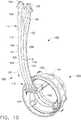
燃焼室62はエンジン外側ケーシング18内に収容される。燃料は、たとえば図11、12、13および14に示した例のように、燃料ノズルによって燃焼室に供給される。液体燃料は、たとえば図2、4、6、および10に示した単体導管105を介するように、導管を介して、燃料ノズルへ輸送される。単体構造を有しない他の導管105が、液体燃料を燃料ノズルへ輸送するのに、代替として使用されてよい。単体導管105などの燃料供給導管は、ステム102内に位置してよく、燃料ディストリビュータ先端部190と結合されてよい。パイロット燃料、および主燃料は、たとえば、図15および20に示したように、燃料ノズル先端部アセンブリにより燃焼器26内に噴射される。タービンエンジンの作動中、当初、パイロット燃料は、始動およびアイドリング運転などの所定のエンジン作動状態の間、パイロット燃料通路153(たとえば、図10参照)を介して供給される。パイロット燃料は、パイロット燃料出口162を介して、燃料ディストリビュータ先端部190から排出される。追加出力が要求されるとき、主燃料が主燃料通路151、152(たとえば、図10参照)を介して供給され、主燃料は主燃料出口161を使用して噴射される。 The
図15〜25は、単体ディストリビュータ300の本発明の例示的実施形態を示す。図2〜14は、導管105および単体ディストリビュータ300を含む燃料ディストリビュータ100の例示的実施形態を示す。用語「単体」は、本明細書に記載のディストリビュータ300などの関連構成部品が、製造中に一体成形として製造されることを意味するために、本出願では使用される。したがって、単体構成部品は、その構成部品にとっての一体式構造を有しており、接合されて単一構成部品を形成する複数の構成部品製の構成部品とは異なる。 FIGS. 15-25 illustrate an exemplary embodiment of the present invention for a
図2は、本発明の例示的実施形態による燃料ディストリビュータ100の等角図を示す。図2に示した例示的燃料ディストリビュータ100には、導管105および単体ディストリビュータ300が含まれる。導管105およびディストリビュータ300は、以降に本明細書に記載の方法を使用して製造される、図2に示した単体構造を有してよい。あるいは、燃料ディストリビュータ100は単体ディストリビュータ300および導管105を個別に製造し、単体ディストリビュータ300が導管105と流れ連通するように、適切な従来の接続手段を使用して結合することにより製作してよい。 FIG. 2 shows an isometric view of a
図2〜10に示したように、導管105は導管本体106内に位置する1つまたは複数の流路108を含む。導管105は入口端部111および出口端部112を有する。流体は入口端部111で導管105に入り、出口端部112に向かって縦方向101に流れ、出口端部112で導管105から出る。図3は、図2に示した例示的単体導管の横軸断面図を示す。図2に示したように、例示的単体導管105は外側輪郭140と、導管本体106内に位置する多数の流路108を有する導管本体106を含む。流路は断面形状120および内側輪郭141を有する。図3に示した例示的実施形態では、4つの通路があり、それぞれが円形断面形状を有する。図2に示したように、流路は異なる寸法を有してよい。たとえば、図2に示した例示的実施形態では、2つの外側に位置する通路155、157はパイロット燃料流路であり、2つの内側の通路151、152は、燃料ディストリビュータ100に使用する主燃料流路である。それぞれの流路108は、たとえば、流路108の内側輪郭141を導管本体106の外側輪郭140から分離する、品目114として示したような、壁を有する。導管本体106内に隣接して位置する流路108は、たとえば、品目116として示したような、分離壁によって相互に分離されている。図2および3に示した例示的実施形態では、主流路151、152はそれぞれ約0.060インチ(約0.152cm)と0.150インチ(約0.381cm)の間の直径を有し、パイロット流路155、157はそれぞれ約0.040インチ(約0.102cm)と0.150インチ(約0.381cm)の間の直径を有する。壁114は、約0.020インチ(約0.051cm)と0.060インチ(約0.152cm)の間の厚さを有する。分離壁116は約0.020インチ(約0.051cm)と0.060インチ(約0.152cm)の間の厚さを有する。 As shown in FIGS. 2-10, the
円形断面は通常、製造上の要件に基づき、流路で選択されてきた。しかし、たとえば熱応力に曝される燃料回路におけるなど、特定の場合には、非円形断面を有する流路118を有することは有利である。流路108の内側部分および導管本体106の外側輪郭140を適正に輪郭を形作ることによって、流路108の応力集中を軽減することができる。流路108は円形(図3参照)であってもよいし、楕円形(図5)であってもよい。円形通路であれば、縦は短いが、幅が広くなるであろう。楕円形通路であれば、幅は狭いが、縦が長くなるであろう。幅が狭くなると、導管105の供給部分でより可撓性をもたらし、導管本体106の熱応力の軽減を促進する。図4は、本発明の代替例示的実施形態による導管105を有する燃料ディストリビュータの等角図であり、そこでは流路118は非円形断面形状121を有する。図5は、図4に示した例示的導管105の横軸断面図を示す。各流路118の内側輪郭141は円形、非円形、または円形と非円形の適正な組合せであるように選択することができる。図5は、円形輪郭を備えた1つの流路と、非円形輪郭141を備えた3つの流路118とを有する導管105の例示的実施形態を示す。各流路118は、その内側輪郭141を導管本体106の外側輪郭140から分離する壁114を有する。導管本体106内に隣接して位置する流路118は、分離壁116により相互に分離される。図5に示した例示的実施形態では、非円形流路118は、約0.004平方インチ(約0.026cm2)と0.018平方インチ(約0.116cm2)の間の断面積を有し、円形パイロット流路は、約0.005平方インチ(約0.0323cm2)の断面積を有する。壁114は、約0.020インチ(約0.051cm)と0.060インチ(約0.152cm)の間の厚さを有する。分離壁116は、約0.020インチ(約0.051cm)と0.060インチ(約0.152cm)の間の厚さを有する。Circular cross-sections have usually been selected in the flow path based on manufacturing requirements. However, in certain cases, such as in a fuel circuit that is exposed to thermal stress, it is advantageous to have a
図2〜5に示した導管105の例示的実施形態では、流路108の断面形状120、121は導管105の入口端部111から出口端部112まで実質的に一定を維持する。同様に、各流路108の断面積は、導管105の入口端部111から出口端部112まで実質的に一定であってよい。あるいは、流路108の断面積は、燃料ノズルのディストリビュータ先端部190内で適正な流量特性を達成するように、導管105の入口端部111から出口端部112まで、望ましくは実質的に一様に変化してもよい。たとえば、入口端部111と出口端部112の間で、望ましくは実質的に一様に流量範囲を減少することにより、導管105内のいくつかの流路108の流体を加速することが可能である。 In the exemplary embodiment of the
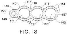
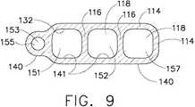
いくつかの用途では、入口端部111と出口端部112の間で、導管105の流路108の内側輪郭141および断面積を変化させることが有利である。図6〜9は、入口端部111近くの第1断面形状131および出口端部112近くの第2断面形状132を有する、4つの流路108を有する導管105の例示的実施形態を示す。断面形状141は、入口端部111近くの第1断面形状131と出口端部112近くの第2断面形状132の間で実質的に一様に変化する。図7〜9は、入口端部111近く、出口端部112のところ、および入口端部111と出口端部112の間の中間位置での、導管105の横軸断面を示す。図7〜9に示すように、第1断面形状131は、4つの通路108のそれぞれが円形である。出口端部112近くの第2断面形状132は、流路のうち3つは非円形であり、第4通路(パイロット通路153)は円形のままである。図8は、中間位置での断面を示し、3つの流路118について円形断面から非円形断面への変化を示す。 In some applications, it is advantageous to vary the
断面形状131、132を変化させるのに加えて、熱応力および重量を減少させるために導管105の壁114および分離壁116の厚さを変化させることが有利である場合がある。たとえば、導管105は、導管105の熱応力を減少させるために、入口端部111近くのバルブろう付け領域からのより厚い部分から、ディストリビュータ先端部190近くに位置する出口端部112近くのより薄い部分へ変化してよい。燃料通路108の壁の厚さ114は、図7に示すように重量を減少させるために、特定の断面で実質的に一定に維持してよい。あるいは、特定の断面では、導管106の外側輪郭140および流路108の壁の厚さ114は、図5に示すように、右端と左端の流路の間で平坦な外側表面を獲得するように輪郭を形作ってよい。断面位置における熱応力プロファイルに基づいて、導管105の異なった断面位置で、上記の手段の組合せを有することが有利である場合もある。導管105の断面および外側輪郭140は、導管本体106(図7〜9参照)の通路の形状に概して適合するように成形してよい、またはそれらは滑らかな外側表面(図3、5参照)を有するように成形してよい。導管105の燃料ノズル用途では、下記のように、パイロット供給導管を介して流れる燃料が、導管本体106および導管本体内に位置する流体通路を冷却し、熱応力の減少を促進するように、1つまたは複数のパイロット供給導管を位置することは可能である。 In addition to changing the
図10は、燃料ノズルの液体燃料を輸送するために使用する例示的単体導管105の部分的断面等角図である。例示的実施形態では、単体導管105には、燃料ノズル内への主燃料通路として役割を果たす導管本体106内に位置する流路108と、導管本体106内で延びるパイロット燃料通路153とが含まれる。パイロット燃料通路153からの燃料は、パイロット供給チューブ154により燃料ノズル内に導かれ、パイロット燃料出口162を介して出る。いくつかの単体導管105では、たとえば図10に示したように、2つ以上のサブ通路109、110に枝分かれする流路108を有することは有利である。単体導管105を燃料ノズルに適用するために図10に示したように、流路108は第1主通路151と第2主通路152に枝分かれする。液体燃料は主通路入口126を介してノズル内に供給され、流路108に入る。次に、燃料流は2つの流れに枝分かれし、一方は第1主通路151を介し、他方は第2主通路152を介して、その後ディストリビュータ先端部190に入る。図10に示したように、主燃料通路108、サブ通路151、152、およびパイロット燃料通路153は、入口端部111と出口端部112の間で、導管本体106で一般的に縦方向101に軸に沿って延びる。 FIG. 10 is a partial cross-sectional isometric view of an exemplary
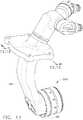
本明細書に記載のように導管105を有し、ガスタービンエンジン燃料ノズルで使用される、例示的燃料ディストリビュータ100が、図11〜13に示してある。例示的実施形態では、単体導管105は、ガスタービンエンジン10に搭載するためのフランジ160を有する、ステム102内に位置する。単体導管105は、ステムの内側と、単体導管105の導管本体106との間に隙間107ができるように、ステム102内に位置する。隙間107は、熱、およびガスタービンエンジンの燃料ノズルを囲む他の悪環境条件から、単体導管105を絶縁する。単体導管105の追加冷却は、隙間107内の循環空気により達成される。単体導管105は、ろう付けなどの従来の接続手段を使用してステム102に接続される。あるいは、単体導管105およびステム102は、たとえば、本明細書に記載の、直接レーザ金属焼結のように、迅速製造方法により製造されてよい。例示的実施形態では、燃料ディストリビュータ先端部190は、主燃料通路(第1主通路151および第2主通路152)ならびにパイロット燃料通路153が、たとえば図13に示したように、燃料ディストリビュータ300と流れ連通して結合するように、単体導管105およびステム102から延びる。詳細には、主燃料通路151、152は、燃料ディストリビュータ300内で画定された主燃料回路に、流れ連通して結合される。同様に、1次パイロット通路155および2次パイロット通路157は、燃料ノズル内に内向きに半径方向に配置された、対応するパイロット噴射器(たとえば、図15に示した品目163、563参照)と流れ連通して結合される。導管105は単体導管(すなわち、単体構造を有する)として本明細書で上述したが、当該技術分野で知られている方法を使用して他の適切な製造構造物を有する導管105を使用することが可能であることは、当業者には明白であろう。 An
ディストリビュータ先端部190およびディストリビュータ300を有する例示的燃料ノズルの等角図が、図14に示してある。図15は、図14に示した例示的燃料ノズルの例示的ディストリビュータ先端部190の軸方向断面図である。例示的ディストリビュータ先端部190は、上記のように、供給導管105から燃料流を受け取り、下記のように主燃料通路およびパイロット燃料通路などの、燃料ノズルの様々な位置に燃料を分配するディストリビュータ300を含む。図15〜20は、燃料を燃料ノズル先端部アセンブリ68で分配する、2つの主流路304、305および2つのパイロット流路402、502を有する、本発明の例示的実施形態を示す。図21〜23は、2つの主流路604、603および単独のパイロット流路602を有する、本発明の別の例示的実施形態を示す。 An isometric view of an exemplary fuel nozzle having a
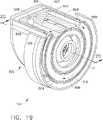
図15〜20に示した例示的ディストリビュータ300は、本明細書に記載の主流路およびパイロット流路を含む、ディストリビュータリング本体301を含む。ディストリビュータ300の主流路302、303は、供給導管105の対応する主流路(たとえば、図3の品目151、152など)と流れ連通している。本明細書に示され、記載された例示的主燃料通路はそれぞれ、供給導管105から、ディストリビュータ軸11の周りに周方向で位置する2つのアーチ形部304、305に燃料流を輸送する入口部307を含む。 The
図16を参照すれば、そこに示した視角では、主流路は左軸部(品目302として示す)および右軸部(品目303として示す)を含む。左軸部302および右軸部303内の流れは、ディストリビュータ軸11に関して、一般的に軸方向にある。主流路左軸部302からの流量は、左円周部304に入る。左主流路円周部304は、ディストリビュータ軸11の周りを一般的に周方向で配向されるアーチ形を有する。同様に、主流路右軸部303からの流量は、右円周部305に入る。右主流路円周部305は、ディストリビュータ軸11の周りを一般的に周方向で配向されるアーチ形を有する。主流路左円周部304および右円周部305は、一般的に同じ軸位置(図15参照)に位置し、2つの周方向経路からの流れが混合するのを防ぐ壁306によって分離される。主流路の流体流れ方向は、左通路302、304には品目317として、右通路303、305には品目318として、図16に示される。燃料は、主通路右円周部305では周方向で時計回り方向に、主通路左円周部304では反時計回り方向に流れる。2つの軸流路302、303および対応する円周通路304、305が、本明細書に記載の実施形態に示してあるが、流路に他の配置を有することは可能であり、単体ディストリビュータ300の他の配向が本発明の範囲内にあることは、当業者には理解されたい。 Referring to FIG. 16, at the viewing angle shown there, the main flow path includes a left axis (shown as item 302) and a right axis (shown as item 303). The flow in the
図16に示すように、主流路304、305からの燃料流は、ディストリビュータリング本体301に位置し、ディストリビュータ軸11の周りに周方向で配列される複数の主流出口通路308により、ディストリビュータ300から周方向外向きに導かれる。図15〜25に示した例示的実施形態では、各主流出口通路308は燃料ポスト310の内側に位置する。燃料ポスト310はディストリビュータリング本体301の一部として形成される。各出口通路308は、主流路304、305と流れ連通する。主流路304、305からの加圧燃料は、出口通路308に入り、燃料噴射309(図16参照)としてディストリビュータ300から噴出される。本明細書に記載の本発明のいくつかの実施形態では、主流路304、305を、通路304、305の断面領域(図16で「P」と印す)が円周方向で一様に変化するようになすことが可能である。断面領域「P」の変化は、ディストリビュータリング本体301のディストリビュータ軸の周りで円周方向に配列される複数の出口通路308内への、通路304、305内の燃料流としての主流路304、305内の一定圧力を維持するように、知られている方法を使用して、寸法決めされる。 As shown in FIG. 16, the fuel flow from the
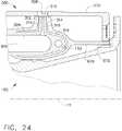
前記のように、ガスタービンエンジンで使用される燃料ノズルなどの、燃料ノズルは高温に曝される。このような高温への曝露は、場合によっては、たとえば、ディストリビュータリング本体301に位置する、出口通路308などの燃料通路で燃料コークス化および閉塞をもたらす。ディストリビュータ300の燃料コークス化および/または閉塞を緩和する1つの方法は、通路308を悪熱環境から保護するために、熱シールドを使用することである。図16および図24に示した本発明の例示的実施形態では、燃料ポスト310は、燃料ポスト310を囲む熱シールドによって保護される。図24に示した例示的実施形態は、熱ポスト310を囲む、前方熱シールド312および後方熱シールド314を含む。図16に示したように、熱シールドは、ディストリビュータ軸11の周りの円周方向に主流路304、305の少なくとも一部も囲んでよい。熱シールド314、312は、燃料通路(たとえば、図16および24で品目308、304、305として表示)の壁と、熱シールド312、314の間に絶縁用隙間316ができるように製造される。絶縁用隙間316は、燃料通路に悪熱環境からのさらなる保護を提供する。熱シールドは、たとえば、一般にガスタービンエンジンで使用されるコバルト基合金およびニッケル基合金などの、高温に耐える能力を備えた任意の適正な材料で製造することができる。たとえば図15〜25に示したような、本発明の例示的実施形態では、ディストリビュータ300は、ディストリビュータリングリング本体301、流路302、303、305、306、燃料ポスト310、熱シールド312、314、および隙間316が、一体式構造を有するように形成される単体構造を有する。このような単体ディストリビュータ300を製造する方法は、以降に本明細書に記載される。 As mentioned above, fuel nozzles, such as fuel nozzles used in gas turbine engines, are exposed to high temperatures. Such exposure to high temperatures may result in fuel coking and blockage in fuel passages such as, for example,
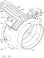
本発明の別の態様では、単体ディストリビュータ300は、ディストリビュータリング本体301を冷却し、流路を悪熱環境から保護するために、パイロット燃料を流すための、たとえば図18に品目402、502として示したような、少なくとも1つの流路を有する。図15〜20は、本明細書では1次パイロット流路402および2次パイロット流路502と呼ぶ、2つのパイロット燃料冷却流路を有する本発明の例示的実施形態を示す。図15を参照すれば、1次パイロット流路402からの燃料は、1次パイロット燃料噴射器163を介して燃料ノズルから出て、2次パイロット燃料流路502からの燃料は、2次パイロット燃料噴射器563を介して燃料ノズルから出る。ディストリビュータ300の1次パイロット流路402は、供給導管105(たとえば、図3参照)の対応するパイロット1次通路155と流れ連通する。同様に、ディストリビュータ300の2次パイロット流路502は、供給導管105(たとえば、図3参照)の対応するパイロット2次通路157と流れ連通する。 In another aspect of the present invention, the
図17を参照すれば、ディストリビュータリング本体301の1次パイロット流路402は、たとえば、供給導管105のパイロット1次通路155からなどの、1次パイロット燃料の受取位置として役目を果たす、1次パイロット入口401を含む。1次パイロット流路402は、1次パイロット流流入路403と、ディストリビュータ軸11に関して円周方向に配向される円周部分404とをさらに含む。図17に示した例示的実施形態では、1次パイロット流流入路は、ディストリビュータ軸11に関して一般的に軸方向を有するものとして示される。他の配向も、1次パイロット流流入路403に使用してよい。流入路403からの1次パイロット燃料流は、1次流路402の円周部分404に入り、図17に品目406として示した流れ方向の矢印で指示したように、円周方向に流れる。1次パイロット流路402のより低い温度のパイロット燃料流は、前記した高温への曝露の悪影響を減少するために、ディストリビュータリング本体301と、ディストリビュータ300内に位置する燃料流路とに冷却をもたらす。図18を参照すれば、円周流路404からの1次パイロット燃料流(品目406参照)は、ディストリビュータ300に位置する1次パイロット流流出路405に入る。図18に示した例示的実施形態では、1次パイロット流流出路405は、ディストリビュータ軸11に関して一般的に軸方向を有するものとして示される。他の配向も、1次パイロット流流出路405に使用してよい。図18に示した例示的実施形態では、ディストリビュータ300は、流出路405と流れ連通する1次パイロット供給チューブ部154を含み、1次パイロット燃料をディストリビュータ軸11の方向に半径方向に内向き、および1次燃料出口162の方向に配向する。第1パイロット燃料は、1次パイロット燃料出口162を介してディストリビュータリング本体301から出て、1次パイロット燃料噴射器163によって燃料ノズルから噴出される。図15に示した例示的実施形態では、第1パイロット流路402の円周部404は、主流路304、305から軸方向前方位置でディストリビュータリング本体301に位置する。代替実施形態では、第1パイロット流路402の円周部404は、主流路304、305から軸方向後方位置に位置する。 Referring to FIG. 17, the primary
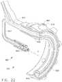
図15および19を参照すれば、本発明の例示的実施形態には、2次パイロット流路502が含まれる。2次パイロット燃料は、図19で流れ方向の矢印506により示されるように、2次パイロット流路502を介して流れる。ディストリビュータリング本体301に位置する2次パイロット流路502は、たとえば、供給導管105のパイロット2次通路157からのように、2次パイロット燃料のための受取位置として役目を果たす2次パイロット入口部507を含む。2次パイロット流路502は、2次パイロット流流入路503と、ディストリビュータ軸11に関して円周方向に配向する円周部504とをさらに含む。図19に示した例示的実施形態では、2次パイロット流流入路503は、ディストリビュータ軸11に関して一般的に軸方向を有するものとして示される。他の配向も、2次パイロット流流入路503に使用してよい。流入路503からの2次パイロット燃料流は、2次流路502の円周部504に入り、図19に品目506として示した流れ方向の矢印によって指示されるように、円周方向に流れる。2次パイロット流路502のより低い温度のパイロット燃料流は、前記した高温への曝露の悪影響を減少するために、ディストリビュータリング本体301と、ディストリビュータ300内に位置する燃料流路とに冷却をもたらす。図19を参照すれば、円周流路504からの2次パイロット燃料流(品目506参照)は、ディストリビュータ300に位置する2次パイロット流流出路505に入る。図19に示した例示的実施形態では、2次パイロット流流出路505は、ディストリビュータ軸11に関して一般的に軸方向を有するものとして示される。他の配向も、2次パイロット流流出路505に使用してよい。図15〜20に示した例示的実施形態では、2次パイロット流路502の円周部504は、主流路304、305から軸方向後位置のディストリビュータリング本体301に位置する。代替実施形態では、2次パイロット流路502の円周部504は、主流路304、305から軸方向前方位置に位置してよい。図17および19を参照すれば、円周方向の1次パイロット燃料の流れ方向406は反時計回りであり、円周方向の2次パイロット燃料の流れ方向506は時計回りである。本発明の代替実施形態では、1次および2次燃料パスの流れ方向は、異なる向きを有しても、同じ向きであってもよい。 With reference to FIGS. 15 and 19, an exemplary embodiment of the present invention includes a secondary
本発明の一態様では、ディストリビュータリング301の1次パイロット流路404および2次パイロット流路504は、たとえば、図15、17および19の品目316のような、絶縁用隙間によって保護される。同様に、たとえば、図15および18の品目516のような、絶縁用隙間は、パイロット噴射器の少なくとも一部の周りに提供される。これらの絶縁用隙間は、燃料流パスにディストリビュータリング本体301が経験する高温から少なくともいくらかの保護を提供し、流れパスおよび噴射器のコークス化および/または閉塞の発生率を減少させるのを助ける。示した例示的実施形態では、絶縁用隙間は約0.015インチ(約0.038cm)と0.025インチ(約0.064cm)の間の幅を有する。本発明の別の態様では、図15〜24の品目316、516および616などの絶縁用隙間は、以降に本明細書に記載の方法を使用して、単体構造を有するディストリビュータリング本体301内に一体的に製造することができる。 In one aspect of the invention, the
単一パイロット噴射器663を有する燃料ノズルのための単一パイロット流路602を有する本発明の例示的実施形態が、図21〜24に示される。燃料ディストリビュータ100の例示的実施形態は、これまでに本明細書に記載のものと同様に、主流路603、604の燃料ポスト610、主燃料出口661、前方熱シールド部612、後方熱シールド部614、および絶縁用隙間616を有するディストリビュータ本体601を含む。前方および後方熱シールド部は、一体成形熱シールド611(図23参照)に結合してよい。パイロット噴射器663は、パイロット燃料流をパイロット供給チューブ654(図22参照)から受け取る。パイロット燃料流パスは、ディストリビュータリング本体601を冷却するパイロット燃料を流すために、これまでに本明細書に記載のような円周部を有する。図21〜24に示した例示的実施形態は、流路を悪熱環境から保護する、たとえば図22に示すような絶縁用隙間616をさらに含む。本発明の一態様では、図21に示したディストリビュータ300の例示的実施形態は、以降に本明細書に記載の方法を使用して単体構造を有する。 Exemplary embodiments of the present invention having a single
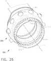
本発明の別の態様では、ディストリビュータ300は、ディストリビュータリング本体301の前方端部に位置し、それと同軸に位置する、環状リング670(図15、21、23参照)を有する。環状リング670は、環状リング壁672を含み、ディストリビュータリング本体301から軸方向に前方に延びる。本発明の一態様では、環状リング670は軸および円周方向に延びるスロット674を有する。軸スロット674は、組立中に燃料ノズルの他の部品と係合し、燃料ノズル内で組立中にディストリビュータ300の正確な配向を確かにするための手段を提供する。本発明の別の態様では、環状リング壁672中に広がる衝突冷却孔680が提供される。燃料ノズル作動中に、冷却用空気(図示せず)が半径方向内側方向に冷却孔680を通過し、燃料ノズルの隣接する部品に衝突し、これらの部品に冷却をもたらす。図25に示した例示的実施形態では、環状リング壁は、0.025インチ(約0.064cm)と0.035インチ(約0.089cm)の間の厚さを有する。2列の冷却孔680が使用され、各列は40から60の孔を有し、各孔は約0.025インチ(約0.064cm)と0.040インチ(約0.102cm)の間の直径を有する。本発明の一態様では、図25に示したディストリビュータ300の例示的実施形態は、以降に本明細書に記載の方法を使用する単体構造を有する。例示的実施形態では、図25に示した単体ディストリビュータ300は、単体構造の間に形成される冷却孔680およびスロット674を有してよい。 In another aspect of the present invention, the
図15〜20に示した単体ディストリビュータ300の例示的実施形態、および図21〜25に示した単体ディストリビュータ300の代替実施形態は、直接金属レーザ焼結(DMLS)、レーザネットシェープ製造(LNSM)、電子ビーム焼結および他の製造で知られているプロセスなどの、迅速製造プロセスを使用して製造できる。DMLSは、本明細書に記載の単体導管105、単体ディストリビュータ300および単体燃料ディストリビュータ100を製造する好ましい方法である。 The exemplary embodiment of the
図26は、本明細書に記載の単体導管105、単体ディストリビュータ300および単体燃料ディストリビュータ100を製作する方法200の例示的実施形態を説明する流れ図である。方法200には、直接金属レーザ焼結(DMLS)を使用して単体ディストリビュータ300(図15〜25に図示)を製作するステップが含まれる。DMLSは、構成部品の3次元情報、たとえば、3次元コンピュータモデルを使用して金属構成部品を製作する、知られている製造プロセスである。3次元情報は複数のスライスに変換され、各スライスは所定の高さのスライスの構成部品の断面を定義する。次に、構成部品は、完了するまで、スライスごとに、または層ごとに、「ビルドアップ」される。構成部品の各層は、レーザを使用して金属粉末を溶解することで形成される。 FIG. 26 is a flow diagram illustrating an exemplary embodiment of a
したがって、方法200には、単体ディストリビュータ300の3次元情報を決定するステップ205と、各スライスが単体ディストリビュータ300の断面層を定義する複数のスライスに3次元情報を変換するステップ210とが含まれる。次に、単体ディストリビュータ300は、DMLSを使用して製作され、またはより詳細には、各層が、レーザエネルギーを使用して金属粉末を溶解することによりステップ215で次々に形成される。各層は約0.0005インチ(約0.0013cm)と約0.001インチ(約0.0025cm)の間の寸法を有する。単体ディストリビュータ300は、任意の適正なレーザ焼結機械を使用して製作してよい。適正なレーザ焼結機械の例には、限定はされないが、ミシガン州NoviのEOS of North America、Inc.から入手可能なEOSINT.RTM.M270DMLSマシン、PHENIX PM250マシン、および/またはEOSINT.RTM.M 250 Xtended DMLSマシンが含まれる。単体ディストリビュータ300を製作するのに使用する金属粉末は、望ましくは、コバルトクロムを含む粉末であるが、限定はされないが、HS188およびINCO625などの、任意の他の適正な金属粉末であってよい。金属粉末は、約10ミクロンと74ミクロンの間の粒径を有することができるが、望ましくは約15ミクロンと約30ミクロンの間である。 Accordingly, the
単体ディストリビュータ300を製造する方法は、好ましい方法としてDMLSを使用すると本明細書には記載されているが、層ごとの構築または追加製作を使用する任意の他の適正な迅速製造方法も使用できることは、当業者には理解されよう。これら代替の迅速製造方法には、限定はされないが、選択的レーザ焼結(SLS)、インクジェットおよびレーサジェットなどによる3D印刷、ステレオリトグラフィ(SLS)、直接選択的レーザ焼結(DSLS)、電子ビーム焼結(EBS)、電子ビーム溶解(EBM)、レーザ技術ネットシェープ法(LENS)、レーザネットシェープ製造(LNSM)および直接金属堆積(DMD)が含まれる。 Although the method of manufacturing the
タービンエンジン(図11〜25参照)の燃料ディストリビュータ100用の単体ディストリビュータ300が含む構成部品および継手は、知られている燃料ノズルより少ない。詳細には、上記単体ディストリビュータ300は、たとえば本明細書に含まれる図15〜23に品目302、304、402、403、404、405、503、505および602として示したような、1つまたは複数の流路を有する一体形ディストリビュータリング本体301を使用するので、必要とする構成部品はより少ない。結果として、記載の燃料ディストリビュータ100は、知られている燃料ディストリビュータに対し、より軽い、よりコストがかからない代替を提供する。さらに、ディストリビュータ300用または燃料ディストリビュータ100用の記載の単体構造は、知られているディストリビュータと比較して、漏れまたは故障の機会が少なくなり、より容易に修理が可能になる。 A
本明細書で使用されるように、単数形で列挙され又は数詞がないステップは、複数を除外することが明確に説明されていない限り、複数の前記要素またはステップを除外しないと理解されるべきである。本明細書に記載および/または例示した単体ベンチュリ500、600の要素/構成部品/ステップなどを導入するとき、数詞がないことや「前記」などの冠詞は、1つまたは複数の要素/構成部品/などがあることを意味することを意図する。用語「comprising(含む)」「including(含む)」および「having(有する)」は包括的であり、列挙した要素/構成部品/など以外に追加の要素/構成部品/などがあり得ることを意味することを意図する。さらに、本発明の「一実施形態」に言及することは、列挙した特徴も組み込む追加の実施形態が存在することを除外すると解釈されることは意図していない。 As used herein, a step recited in the singular or lacking a number should be understood not to exclude a plurality of said elements or steps unless specifically stated to exclude a plurality. It is. When introducing the elements / components / steps, etc. of the single venturi 500, 600 described and / or illustrated herein, articles such as the absence of a numeral or “above” may refer to one or more elements / components. It is intended to mean that there is / etc. The terms “comprising”, “including” and “having” are inclusive and mean that there may be additional elements / components / etc. In addition to the listed elements / components / etc. Intended to be. Furthermore, references to “one embodiment” of the present invention are not intended to be interpreted as excluding the existence of additional embodiments that also incorporate the recited features.
本明細書に記載の方法ならびに導管105、ディストリビュータ300、および燃料ディストリビュータ100などの物品は、液体燃料をタービンエンジンに供給することとの関連で記載されているが、本明細書に記載の導管105、ディストリビュータ300、および燃料ディストリビュータ100ならびにその製造の方法は、燃料ディストリビュータまたはタービンエンジンに限定されないことは理解されたい。本明細書に含まれる図面に描かれた導管105、ディストリビュータ300または燃料ディストリビュータ100の構成部品は、本明細書に記載の特定の実施形態に限定はされず、むしろ、これらは本明細書に記載の他の構成部品と独立して、個別に利用することが可能である。 Although the methods described herein and articles such as
本書は、最良の形態を含み、本発明を開示するために、また当業者が本発明を製造および使用できるようにするために、例示を使用するものである。本発明の特許性のある範囲は、特許請求の範囲により定義され、当業者が気付く他の例示も含まれる場合がある。このような他の例示は、その例示が本特許請求の範囲の文言上の用語と異ならない構造要素を有する場合、またはその例示が本特許請求の範囲の文言上の用語とごくわずかな差異を伴う等価の構造要素を含む場合は、本特許請求の範囲内にあることを意図するものである。 This written description uses the examples to disclose the invention, including the best mode, and also to enable any person skilled in the art to make and use the invention. The patentable scope of the invention is defined by the claims, and may include other examples that occur to those skilled in the art. Such other examples may have structural elements that do not differ from the wording terms of the claims, or the illustrations may differ only slightly from the wording terms of the claims. The accompanying equivalent structural elements are intended to be within the scope of the claims.
10 タービンエンジン
11 ディストリビュータ軸
12 軸方向中心線軸
16 ファンセクション
18 外側ケーシング
20 環状入口
22 ブースタ
24 多段式軸流圧縮器
26 燃焼器
28 タービン
30 ドライブシャフト
32 タービン
34 ドライブシャフト
36 排気ノズル
38 軸流ファンロータ
40 環状ファンケーシング
42 ガイドベーン
44 ファンブレード
46 下流セクション
48 導管
50 空気流
52 入口
54 空気流
56 空気流
58 空気流
60 燃焼生成物/燃焼ガス
62 燃焼室
64 入口
66 出口
68 ノズル先端部アセンブリ
69 出口
72 タービンノズル
74 ノズルベーン
100 ディストリビュータ
101 縦方向
102 ステム
105 導管
106 導管本体
107 隙間
108 流路
109 サブ通路
110 サブ通路
111 入口端部
112 出口端部
114 壁
116 分離壁
118 流路
120 断面形状
121 断面形状
126 主通路入口
131 断面形状
132 断面形状
140 外側輪郭
141 内側輪郭
151 主燃料通路
152 主燃料通路
153 パイロット燃料通路
154 パイロット供給チューブ
155 通路
157 通路
160 フランジ
161 主燃料出口
162 パイロット燃料出口
163 パイロット燃料噴射器
190 燃料ディストリビュータ先端部
300 ディストリビュータ
301 ディストリビュータリング本体
302 主流路
303 主流路
304 主流路
305 主流路
306 壁
307 入口部
308 主流出口通路
309 燃料噴射
310 燃料ポスト
312 熱シールド
314 熱シールド
316 絶縁用隙間
317 流体流れ方向
318 流体流れ方向
401 パイロット入口
402 パイロット流路
403 流入路
404 パイロット流路
405 流出路
406 パイロット燃料の流れ方向
502 パイロット流路
503 流入路
504 パイロット流路
505 パイロット流流出路
506 パイロット燃料の流れ方向
507 パイロット入口部
516 絶縁用隙間
563 パイロット燃料噴射器
601 ディストリビュータリング本体
602 パイロット流路
603 主流路
604 主流路
610 燃料ポスト
611 熱シールド
612 前方熱シールド部
614 後方熱シールド部
616 絶縁用隙間
654 パイロット供給チューブ
661 主燃料出口
663 パイロット噴射器
670 環状リング
672 環状リング壁
674 スロット
680 冷却孔DESCRIPTION OF SYMBOLS 10 Turbine engine 11 Distributor shaft 12 Axial centerline shaft 16 Fan section 18 Outer casing 20 Annular inlet 22 Booster 24 Multistage axial compressor 26 Combustor 28 Turbine 30 Drive shaft 32 Turbine 34 Drive shaft 36 Exhaust nozzle 38 Axial fan rotor 40 annular fan casing 42 guide vane 44 fan blade 46 downstream section 48 conduit 50 air flow 52 inlet 54 air flow 56 air flow 58 air flow 60 combustion product / combustion gas 62 combustion chamber 64 inlet 66 outlet 68 nozzle tip assembly 69 outlet 72 Turbine nozzle 74 Nozzle vane 100 Distributor 101 Longitudinal direction 102 Stem 105 Conduit 106 Conduit body 107 Crevice 108 Channel 109 Sub passage 11 0 Sub-passage 111 Inlet end 112 Outlet end 114 Wall 116 Separating wall 118 Flow path 120 Cross-sectional shape 121 Cross-sectional shape 126 Main passage inlet 131 Cross-sectional shape 132 Cross-sectional shape 140 Outer contour 141 Inner contour 151 Main fuel passage 152 Main fuel passage 153 Pilot fuel passage 154 Pilot supply tube 155 passage 157 passage 160 flange 161 main fuel outlet 162 pilot fuel outlet 163 pilot fuel injector 190 fuel distributor tip 300 distributor 301 distributor ring main body 302 main passage 303 main passage 304 main passage 305 main passage 306 Wall 307 Inlet 308 Main outlet passage 309 Fuel injection 310 Fuel post 312 Heat shield 314 Heat shield 316 Insulation gap 317 Body flow direction 318 Fluid flow direction 401 Pilot inlet 402 Pilot flow path 403 Inflow path 404 Pilot flow path 405 Outflow path 406 Pilot fuel flow direction 502 Pilot flow path 503 Inflow path 504 Pilot flow path 505 Pilot flow outflow path 506 Flow direction 507 Pilot inlet 516 Insulation gap 563 Pilot fuel injector 601 Distributor ring body 602 Pilot flow path 603 Main flow path 604 Main flow path 610 Fuel post 611 Heat shield 612 Front heat shield section 614 Rear heat shield section 616 Insulation gap 654 Pilot supply tube 661 Main fuel outlet 663 Pilot injector 670 Annular ring 672 Annular ring wall 674 Slot 680 Cooling hole
Claims (7)
Translated fromJapanese前記ディストリビュータ(300)が、該ディストリビュータ(300)内に位置する主流路を備え、また、単体構造を有し、
前記主流路が、ディストリビュータ軸(11)の周りで円周方向に配向されるアーチ形部を有し、
前記ディストリビュータ(300)が、
前記主流路のアーチ形部の軸方向前方に位置し且つ前記ディストリビュータ軸(11)の周りで円周方向に配向されるアーチ形部(404)を有する1次パイロット流路(402)と、
前記主流路のアーチ形部の軸方向後方に位置し且つ前記ディストリビュータ軸(11)の周りで円周方向に配向されるアーチ形部(504)を有する2次パイロット流路(502)と
前記ディストリビュータ軸(11)の周りに周方向で配列される前記ディストリビュータリング本体(301)に位置し、それぞれが前記主流路と流れ連通する出口通路(308)を有する複数の燃料ポスト(310)と、
前記複数の燃料ポスト(310)の少なくとも一部を囲む前記ディストリビュータリング本体(301)内に位置する熱シールド(312)と
をさらに含む
ことを特徴とする、ディストリビュータ(300)。A distributor (300) comprising a distributor ring body (301) and a conduit body (106),
The distributor (300) includes a main flow path located in the distributor (300), and has a unitary structure;
The main channel has an arcuate portion oriented circumferentially around the distributor axis (11);
The distributor (300)
A primary pilot flow path (402) having an arcuate portion (404) positioned axially forward of the arcuate portion of the main flow path and oriented circumferentially around the distributor shaft (11);
A secondary pilot channel (502) having an arched portion (504) positioned axially rearward of the arched portion of the main channel and circumferentially oriented around the distributor shaft (11);
A plurality of fuel posts (310) located in the distributor ring body (301) arranged circumferentially around the distributor shaft (11), each having an outlet passage (308) in flow communication with the main flow path; ,
A distributor (300), further comprisinga heat shield (312) positioned within the distributor ring body (301) surrounding at least a portion of the plurality of fuel posts (310 ).
前記ディストリビュータ軸(11)の周りで時計回り方向に流体を輸送することができる第1アーチ形部(305)を有する第1主流路(307)と、
前記ディストリビュータ軸(11)の周りで反時計回り方向に流体を輸送することができる第2アーチ形部(304)を有する第2主流路(308)と
を含む、
請求項1記載のディストリビュータ(300)。The main flow path is
A first main flow path (307) having a first arcuate portion (305) capable of transporting fluid in a clockwise direction around the distributor shaft (11);
A second main channel (308) having a second arcuate portion (304) capable of transporting fluid in a counterclockwise direction around the distributor shaft (11),
The distributor (300) of claim 1.
Applications Claiming Priority (7)
| Application Number | Priority Date | Filing Date | Title |
|---|---|---|---|
| US4411608P | 2008-04-11 | 2008-04-11 | |
| US61/044,116 | 2008-04-11 | ||
| US12/182,526 | 2008-07-30 | ||
| US12/182,526US20090256003A1 (en) | 2008-04-11 | 2008-07-30 | Method of manufacturing a fuel distributor |
| US12/182,500 | 2008-07-30 | ||
| US12/182,500US8336313B2 (en) | 2008-04-11 | 2008-07-30 | Fuel distributor |
| PCT/US2009/037148WO2009148682A2 (en) | 2008-04-11 | 2009-03-13 | Fuel distributor and method of manufacturing |
Publications (3)
| Publication Number | Publication Date |
|---|---|
| JP2011526994A JP2011526994A (en) | 2011-10-20 |
| JP2011526994A5 JP2011526994A5 (en) | 2013-04-25 |
| JP5437362B2true JP5437362B2 (en) | 2014-03-12 |
Family
ID=41162795
Family Applications (7)
| Application Number | Title | Priority Date | Filing Date |
|---|---|---|---|
| JP2011504035AActiveJP5437362B2 (en) | 2008-04-11 | 2009-03-13 | Fuel distributor and method of manufacturing |
| JP2011504034AActiveJP5779499B2 (en) | 2008-04-11 | 2009-03-13 | Unit conduit for transporting fluid and method of manufacturing |
| JP2011504037AActiveJP5419962B2 (en) | 2008-04-11 | 2009-03-16 | Swirler and method of manufacturing |
| JP2011504038APendingJP2011528098A (en) | 2008-04-11 | 2009-03-16 | Venturi and method of manufacture |
| JP2011504087APendingJP2011526976A (en) | 2008-04-11 | 2009-04-03 | Combustor mixer and manufacturing method |
| JP2011504148AWithdrawnJP2011526995A (en) | 2008-04-11 | 2009-04-08 | Repairable fuel nozzle and repair method |
| JP2011504155AWithdrawnJP2011528075A (en) | 2008-04-11 | 2009-04-08 | Method of repairing fuel nozzle components |
Family Applications After (6)
| Application Number | Title | Priority Date | Filing Date |
|---|---|---|---|
| JP2011504034AActiveJP5779499B2 (en) | 2008-04-11 | 2009-03-13 | Unit conduit for transporting fluid and method of manufacturing |
| JP2011504037AActiveJP5419962B2 (en) | 2008-04-11 | 2009-03-16 | Swirler and method of manufacturing |
| JP2011504038APendingJP2011528098A (en) | 2008-04-11 | 2009-03-16 | Venturi and method of manufacture |
| JP2011504087APendingJP2011526976A (en) | 2008-04-11 | 2009-04-03 | Combustor mixer and manufacturing method |
| JP2011504148AWithdrawnJP2011526995A (en) | 2008-04-11 | 2009-04-08 | Repairable fuel nozzle and repair method |
| JP2011504155AWithdrawnJP2011528075A (en) | 2008-04-11 | 2009-04-08 | Method of repairing fuel nozzle components |
Country Status (6)
| Country | Link |
|---|---|
| US (13) | US20090255118A1 (en) |
| JP (7) | JP5437362B2 (en) |
| CA (7) | CA2720253C (en) |
| DE (7) | DE112009000753B4 (en) |
| GB (7) | GB2471233B (en) |
| WO (3) | WO2009148682A2 (en) |
Families Citing this family (204)
| Publication number | Priority date | Publication date | Assignee | Title |
|---|---|---|---|---|
| US7854120B2 (en)* | 2006-03-03 | 2010-12-21 | Pratt & Whitney Canada Corp. | Fuel manifold with reduced losses |
| DE102007050276A1 (en)* | 2007-10-18 | 2009-04-23 | Rolls-Royce Deutschland Ltd & Co Kg | Lean premix burner for a gas turbine engine |
| US20090139236A1 (en)* | 2007-11-29 | 2009-06-04 | General Electric Company | Premixing device for enhanced flameholding and flash back resistance |
| US20090255118A1 (en)* | 2008-04-11 | 2009-10-15 | General Electric Company | Method of manufacturing mixers |
| US20090255256A1 (en)* | 2008-04-11 | 2009-10-15 | General Electric Company | Method of manufacturing combustor components |
| US8806871B2 (en)* | 2008-04-11 | 2014-08-19 | General Electric Company | Fuel nozzle |
| US9188341B2 (en)* | 2008-04-11 | 2015-11-17 | General Electric Company | Fuel nozzle |
| US20090255120A1 (en)* | 2008-04-11 | 2009-10-15 | General Electric Company | Method of assembling a fuel nozzle |
| US8607571B2 (en)* | 2009-09-18 | 2013-12-17 | Delavan Inc | Lean burn injectors having a main fuel circuit and one of multiple pilot fuel circuits with prefiliming air-blast atomizers |
| CA2635410C (en)* | 2008-06-19 | 2010-08-17 | Westport Power Inc. | Dual fuel connector |
| US9464808B2 (en)* | 2008-11-05 | 2016-10-11 | Parker-Hannifin Corporation | Nozzle tip assembly with secondary retention device |
| US8061657B2 (en)* | 2008-12-31 | 2011-11-22 | General Electric Company | Method and apparatus for aircraft anti-icing |
| EP2451988A1 (en)* | 2009-07-07 | 2012-05-16 | Eurocoating S.p.A. | Laser process for producing metallic objects, and object obtained therefrom |
| FR2951245B1 (en)* | 2009-10-13 | 2013-05-17 | Snecma | MULTI-POINT INJECTION DEVICE FOR A TURBOMACHINE COMBUSTION CHAMBER |
| EP2325542B1 (en)* | 2009-11-18 | 2013-03-20 | Siemens Aktiengesellschaft | Swirler vane, swirler and burner assembly |
| US20110247590A1 (en)* | 2010-04-07 | 2011-10-13 | Delavan Inc | Injectors utilizing lattice support structure |
| DE102010019447A1 (en)* | 2010-05-05 | 2011-11-10 | Eos Gmbh Electro Optical Systems | A method for generatively producing a three-dimensional object with reamers and method for creating a corresponding dataset |
| US9175568B2 (en)* | 2010-06-22 | 2015-11-03 | Honeywell International Inc. | Methods for manufacturing turbine components |
| US10054313B2 (en) | 2010-07-08 | 2018-08-21 | Siemens Energy, Inc. | Air biasing system in a gas turbine combustor |
| JP5668352B2 (en)* | 2010-07-30 | 2015-02-12 | 日本電産株式会社 | Axial fan and slide mold |
| US20120137695A1 (en)* | 2010-12-01 | 2012-06-07 | General Electric Company | Fuel nozzle with gas only insert |
| US20120151928A1 (en)* | 2010-12-17 | 2012-06-21 | Nayan Vinodbhai Patel | Cooling flowpath dirt deflector in fuel nozzle |
| US8726668B2 (en)* | 2010-12-17 | 2014-05-20 | General Electric Company | Fuel atomization dual orifice fuel nozzle |
| US8387391B2 (en) | 2010-12-17 | 2013-03-05 | General Electric Company | Aerodynamically enhanced fuel nozzle |
| US9085980B2 (en) | 2011-03-04 | 2015-07-21 | Honeywell International Inc. | Methods for repairing turbine components |
| US20120272660A1 (en)* | 2011-04-29 | 2012-11-01 | Proenergy Services, Llc | Method and assembly for retrofitting a gas turbine combustor end cover |
| US8757087B2 (en)* | 2011-05-24 | 2014-06-24 | Nordson Corporation | Device and method for coating elongate objects |
| JP5772245B2 (en)* | 2011-06-03 | 2015-09-02 | 川崎重工業株式会社 | Fuel injection device |
| US10773863B2 (en) | 2011-06-22 | 2020-09-15 | Sartorius Stedim North America Inc. | Vessel closures and methods for using and manufacturing same |
| US9021675B2 (en) | 2011-08-15 | 2015-05-05 | United Technologies Corporation | Method for repairing fuel nozzle guides for gas turbine engine combustors using cold metal transfer weld technology |
| US8506836B2 (en) | 2011-09-16 | 2013-08-13 | Honeywell International Inc. | Methods for manufacturing components from articles formed by additive-manufacturing processes |
| US9266170B2 (en) | 2012-01-27 | 2016-02-23 | Honeywell International Inc. | Multi-material turbine components |
| US20130192243A1 (en)* | 2012-01-31 | 2013-08-01 | Matthew Patrick Boespflug | Fuel nozzle for a gas turbine engine and method of operating the same |
| US9228498B2 (en)* | 2012-03-01 | 2016-01-05 | Solar Turbines Incorporated | Laser clad fuel injector premix barrel |
| JP5991025B2 (en)* | 2012-05-22 | 2016-09-14 | 株式会社Ihi | Burner and gas turbine combustor |
| US8951303B2 (en) | 2012-06-11 | 2015-02-10 | Ut-Battelle, Llc | Freeform fluidics |
| CA2875800C (en)* | 2012-06-15 | 2017-03-28 | General Electric Company | Fluid conduit |
| US10131010B2 (en) | 2012-06-28 | 2018-11-20 | United Technologies Corporation | Gas turbine fuel nozzle end cover using Au—Ni braze and method producing same |
| US20140003923A1 (en) | 2012-07-02 | 2014-01-02 | Peter Finnigan | Functionally graded composite fan containment case |
| US9120151B2 (en) | 2012-08-01 | 2015-09-01 | Honeywell International Inc. | Methods for manufacturing titanium aluminide components from articles formed by consolidation processes |
| US9289826B2 (en) | 2012-09-17 | 2016-03-22 | Honeywell International Inc. | Turbine stator airfoil assemblies and methods for their manufacture |
| US9400104B2 (en)* | 2012-09-28 | 2016-07-26 | United Technologies Corporation | Flow modifier for combustor fuel nozzle tip |
| DE102012219615A1 (en)* | 2012-10-26 | 2014-04-30 | Röchling Automotive AG & Co. KG | Filler neck with integrated ventilation channel |
| US9322415B2 (en) | 2012-10-29 | 2016-04-26 | United Technologies Corporation | Blast shield for high pressure compressor |
| US9272437B2 (en) | 2012-10-31 | 2016-03-01 | Flow International Corporation | Fluid distribution components of high-pressure fluid jet systems |
| US10072845B2 (en)* | 2012-11-15 | 2018-09-11 | General Electric Company | Fuel nozzle heat shield |
| US10315275B2 (en)* | 2013-01-24 | 2019-06-11 | Wisconsin Alumni Research Foundation | Reducing surface asperities |
| GB201301624D0 (en) | 2013-01-30 | 2013-03-13 | Rolls Royce Plc | A Method Of Manufacturing A Wall |
| US20140216043A1 (en)* | 2013-02-06 | 2014-08-07 | Weidong Cai | Combustor liner for a can-annular gas turbine engine and a method for constructing such a liner |
| US9377201B2 (en) | 2013-02-08 | 2016-06-28 | Solar Turbines Incorporated | Forged fuel injector stem |
| US9267689B2 (en) | 2013-03-04 | 2016-02-23 | Siemens Aktiengesellschaft | Combustor apparatus in a gas turbine engine |
| DE102013203936A1 (en)* | 2013-03-07 | 2014-09-11 | Airbus Operations Gmbh | Generative layer building method for producing a three-dimensional object and three-dimensional object |
| DE102013203938A1 (en)* | 2013-03-07 | 2014-09-25 | Airbus Operations Gmbh | Generative layer building method for producing a three-dimensional object and three-dimensional object |
| US9174312B2 (en) | 2013-03-12 | 2015-11-03 | Honeywell International Inc. | Methods for the repair of gas turbine engine components using additive manufacturing techniques |
| US9267189B2 (en)* | 2013-03-13 | 2016-02-23 | Honeywell International Inc. | Methods for forming dispersion-strengthened aluminum alloys |
| WO2014189602A2 (en) | 2013-03-14 | 2014-11-27 | United Technologies Corporation | Hollow-wall heat shield for fuel injector component |
| US20140367494A1 (en)* | 2013-06-14 | 2014-12-18 | Delavan Inc | Additively manufactured nozzle tip for fuel injector |
| US9310023B2 (en) | 2013-06-20 | 2016-04-12 | The Boeing Company | Methods and systems for distributing inert gas in an aircraft |
| US9322558B2 (en) | 2013-06-27 | 2016-04-26 | Siemens Aktiengesellschaft | Combustor apparatus in a gas turbine engine |
| US9192999B2 (en) | 2013-07-01 | 2015-11-24 | General Electric Company | Methods and systems for electrochemical machining of an additively manufactured component |
| EP2823952A1 (en)* | 2013-07-09 | 2015-01-14 | Siemens Aktiengesellschaft | Adaptation method and production method for components produced by means of SLM |
| EP3052785B1 (en)* | 2013-10-04 | 2020-04-08 | United Technologies Corporation | Swirler for a turbine engine combustor |
| WO2015050987A1 (en) | 2013-10-04 | 2015-04-09 | United Technologies Corporation | Additive manufactured fuel nozzle core for a gas turbine engine |
| WO2015061068A1 (en)* | 2013-10-25 | 2015-04-30 | United Technologies Corporation | System and apparatus for combustion swirler anti-rotation |
| GB201321193D0 (en) | 2013-12-02 | 2014-01-15 | Rolls Royce Plc | A combustion chamber assembly |
| US9995220B2 (en)* | 2013-12-20 | 2018-06-12 | Pratt & Whitney Canada Corp. | Fluid manifold for gas turbine engine and method for delivering fuel to a combustor using same |
| CA2933536C (en)* | 2013-12-23 | 2018-06-26 | General Electric Company | Fuel nozzle structure for air-assisted fuel injection |
| US9884406B2 (en)* | 2014-01-15 | 2018-02-06 | Flow International Corporation | High-pressure waterjet cutting head systems, components and related methods |
| WO2015112384A1 (en) | 2014-01-22 | 2015-07-30 | United Technologies Corporation | Method for additively constructing internal channels |
| EP3097334B1 (en)* | 2014-01-24 | 2018-08-22 | United Technologies Corporation | Fuel fitting |
| US10488047B2 (en) | 2014-01-24 | 2019-11-26 | United Technologies Corporation | Thermally compliant additively manufactured fuel injector |
| EP3102887B1 (en) | 2014-01-24 | 2023-11-15 | RTX Corporation | Axial staged combustor with restricted main fuel injector |
| JP6567537B2 (en) | 2014-02-13 | 2019-08-28 | ゼネラル・エレクトリック・カンパニイ | Anti-coking coating, treatment thereof, and hydrocarbon fluid passage comprising the same |
| US10295186B2 (en)* | 2014-03-28 | 2019-05-21 | Delavan Inc. Of Des Moines Ia | Airblast nozzle with upstream fuel distribution and near-exit swirl |
| US9551490B2 (en) | 2014-04-08 | 2017-01-24 | General Electric Company | System for cooling a fuel injector extending into a combustion gas flow field and method for manufacture |
| US9528705B2 (en) | 2014-04-08 | 2016-12-27 | General Electric Company | Trapped vortex fuel injector and method for manufacture |
| US20150285502A1 (en)* | 2014-04-08 | 2015-10-08 | General Electric Company | Fuel nozzle shroud and method of manufacturing the shroud |
| US9857002B2 (en)* | 2014-05-09 | 2018-01-02 | United Technologies Corporation | Fluid couplings and methods for additive manufacturing thereof |
| US10934890B2 (en)* | 2014-05-09 | 2021-03-02 | Raytheon Technologies Corporation | Shrouded conduit for arranging a fluid flowpath |
| JP5940588B2 (en)* | 2014-06-04 | 2016-06-29 | 三菱日立パワーシステムズ株式会社 | Repair system, repair data providing apparatus, and repair data generation method |
| GB2541575B (en) | 2014-06-04 | 2021-06-09 | Mitsubishi Power Ltd | Additive manufacturing system, modeling-data providing apparatus and providing method |
| US10208673B2 (en)* | 2014-07-03 | 2019-02-19 | United Technologies Corporation | Fuel dispensing apparatus and method of operation |
| US20160003150A1 (en)* | 2014-07-03 | 2016-01-07 | General Electric Company | Igniter tip with cooling passage |
| US20170059163A1 (en)* | 2014-07-11 | 2017-03-02 | United Technologies Corporation | Additively manufactured swirler mount interface for gas turbine engine combustor |
| JP6599862B2 (en)* | 2014-07-11 | 2019-10-30 | 倉敷紡績株式会社 | Bending product |
| JP6301774B2 (en)* | 2014-08-01 | 2018-03-28 | 三菱日立パワーシステムズ株式会社 | Gas turbine combustor |
| FR3025017B1 (en)* | 2014-08-20 | 2016-09-30 | Snecma | CONNECTING DEVICE COMPRISING SEVERAL CONCENTRIC TUBES HANGERS |
| US9528632B2 (en) | 2014-10-14 | 2016-12-27 | General Electric Company | Tortuous path control valve trim |
| US20160304210A1 (en)* | 2014-10-15 | 2016-10-20 | Rosemount Aerospace Inc. | One-piece air data probe |
| US9695542B2 (en) | 2014-11-05 | 2017-07-04 | Haier Us Appliance Solutions, Inc. | Unitary spray nozzle for a washing machine appliance |
| US9869047B2 (en) | 2014-11-05 | 2018-01-16 | Haier Us Appliance Solutions, Inc. | Unitary top panel for a washing machine appliance |
| US9901944B2 (en) | 2015-02-18 | 2018-02-27 | Delavan Inc | Atomizers |
| EP3061557B1 (en) | 2015-02-26 | 2018-04-18 | Rolls-Royce Corporation | Repair of dual walled metallic components using directed energy deposition material addition |
| EP3061556B1 (en) | 2015-02-26 | 2018-08-15 | Rolls-Royce Corporation | Method for repairing a dual walled metallic component using braze material and such component obtained |
| US9939157B2 (en)* | 2015-03-10 | 2018-04-10 | General Electric Company | Hybrid air blast fuel nozzle |
| US10591164B2 (en) | 2015-03-12 | 2020-03-17 | General Electric Company | Fuel nozzle for a gas turbine engine |
| US9927124B2 (en)* | 2015-03-26 | 2018-03-27 | Ansaldo Energia Switzerland AG | Fuel nozzle for axially staged fuel injection |
| EP3076080B1 (en)* | 2015-03-30 | 2020-06-10 | Ansaldo Energia Switzerland AG | Fuel injector device |
| US9874351B2 (en) | 2015-04-14 | 2018-01-23 | General Electric Company | Thermally-coupled fuel manifold |
| GB201508703D0 (en) | 2015-05-21 | 2015-07-01 | Rolls Royce Plc | Additive layer repair of a metallic component |
| US20160362200A1 (en)* | 2015-06-15 | 2016-12-15 | The Procter & Gamble Company | Process and apparatus for making water soluble pouches |
| US10209146B1 (en)* | 2015-06-21 | 2019-02-19 | Florida Turbine Technologies, Inc | Apparatus and process for determining a convective heat transfer coefficient between a moving fluid and a bounding surface |
| US10596717B2 (en) | 2015-07-13 | 2020-03-24 | Flow International Corporation | Methods of cutting fiber reinforced polymer composite workpieces with a pure waterjet |
| US10364751B2 (en)* | 2015-08-03 | 2019-07-30 | Delavan Inc | Fuel staging |
| US10443115B2 (en) | 2015-08-20 | 2019-10-15 | General Electric Company | Apparatus and method for direct writing of single crystal super alloys and metals |
| US10378446B2 (en)* | 2015-11-17 | 2019-08-13 | Delavan Inc | Thermal management for injectors |
| US9879536B2 (en) | 2015-12-21 | 2018-01-30 | General Electric Company | Surface treatment of turbomachinery |
| WO2017117072A1 (en)* | 2015-12-29 | 2017-07-06 | Moen Incorporated | Spray devices and unitarily formed components thereof |
| EP3225915B1 (en)* | 2016-03-31 | 2019-02-06 | Rolls-Royce plc | Fuel injector and method of manufactering the same |
| FR3049982B1 (en)* | 2016-04-12 | 2020-01-17 | Zodiac Aerotechnics | METHOD OF MANUFACTURING A STRAINER, STRAINER, AND EJECTOR COMPRISING SUCH A STRAINER |
| US20170363292A1 (en)* | 2016-06-17 | 2017-12-21 | Pratt & Whitney Canada Corp. | Method of accessing a nozzle tip assembly of a fuel nozzle |
| US11262003B2 (en)* | 2016-06-30 | 2022-03-01 | General Electric Company | Integral fluid conduit |
| US10544683B2 (en) | 2016-08-30 | 2020-01-28 | Rolls-Royce Corporation | Air-film cooled component for a gas turbine engine |
| EP3290804A1 (en)* | 2016-08-31 | 2018-03-07 | Siemens Aktiengesellschaft | A burner with fuel and air supply incorporated in a wall of the burner |
| US20180073390A1 (en) | 2016-09-13 | 2018-03-15 | Rolls-Royce Corporation | Additively deposited gas turbine engine cooling component |
| US10689984B2 (en) | 2016-09-13 | 2020-06-23 | Rolls-Royce Corporation | Cast gas turbine engine cooling components |
| US11192210B2 (en)* | 2016-10-31 | 2021-12-07 | Cummins Inc. | Injector sleeve assembly and method for field repair procedure |
| EP3324120B1 (en)* | 2016-11-18 | 2019-09-18 | Ansaldo Energia Switzerland AG | Additively manufactured gas turbine fuel injector device |
| JP6863718B2 (en)* | 2016-11-21 | 2021-04-21 | 三菱パワー株式会社 | Gas turbine combustor |
| DE102016123323B3 (en) | 2016-12-02 | 2018-03-01 | Eberspächer Climate Control Systems GmbH & Co. KG | vehicle |
| US10220474B2 (en) | 2016-12-02 | 2019-03-05 | General Electricd Company | Method and apparatus for gas turbine combustor inner cap and high frequency acoustic dampers |
| US10228138B2 (en) | 2016-12-02 | 2019-03-12 | General Electric Company | System and apparatus for gas turbine combustor inner cap and resonating tubes |
| US10221769B2 (en) | 2016-12-02 | 2019-03-05 | General Electric Company | System and apparatus for gas turbine combustor inner cap and extended resonating tubes |
| US11149952B2 (en) | 2016-12-07 | 2021-10-19 | Raytheon Technologies Corporation | Main mixer in an axial staged combustor for a gas turbine engine |
| US10801728B2 (en)* | 2016-12-07 | 2020-10-13 | Raytheon Technologies Corporation | Gas turbine engine combustor main mixer with vane supported centerbody |
| EP3361161B1 (en)* | 2017-02-13 | 2023-06-07 | Ansaldo Energia Switzerland AG | Burner assembly for a combustor of a gas turbine power plant and combustor comprising said burner assembly |
| US11274831B2 (en) | 2017-03-13 | 2022-03-15 | Siemens Energy Global GmbH & Co. KG | Fuel injector nozzle for combustion turbine engines including thermal stress-relief vanes |
| GB201704899D0 (en) | 2017-03-28 | 2017-05-10 | Rolls Royce Plc | Fuel injector |
| GB2561190A (en)* | 2017-04-04 | 2018-10-10 | Edwards Ltd | Purge gas feeding means, abatement systems and methods of modifying abatement systems |
| US20180313225A1 (en) | 2017-04-26 | 2018-11-01 | General Electric Company | Methods of cleaning a component within a turbine engine |
| US11407034B2 (en) | 2017-07-06 | 2022-08-09 | OmniTek Technology Ltda. | Selective laser melting system and method of using same |
| US11691866B2 (en) | 2017-11-14 | 2023-07-04 | Sartorius Stedim North America Inc. | System for simultaneous distribution of fluid to multiple vessels and method of using the same |
| JP2021503304A (en) | 2017-11-14 | 2021-02-12 | ザルトリウス ステディム ノース アメリカ インコーポレイテッド | Fluid transfer assembly with junctions with multiple fluid paths |
| US12252391B2 (en) | 2017-11-14 | 2025-03-18 | Sartorius Stedim North America Inc. | System for simultaneous distribution of fluid to multiple vessels and method of using the same |
| US11319201B2 (en) | 2019-07-23 | 2022-05-03 | Sartorius Stedim North America Inc. | System for simultaneous filling of multiple containers |
| US11577953B2 (en) | 2017-11-14 | 2023-02-14 | Sartorius Stedim North America, Inc. | System for simultaneous distribution of fluid to multiple vessels and method of using the same |
| US10557732B2 (en) | 2017-12-07 | 2020-02-11 | Cameron International Corporation | Flowmeters and methods of manufacture |
| US11175045B2 (en)* | 2018-01-04 | 2021-11-16 | General Electric Company | Fuel nozzle for gas turbine engine combustor |
| US10746326B2 (en)* | 2018-01-08 | 2020-08-18 | General Electric Company | Additively manufactured tube array |
| US10808934B2 (en)* | 2018-01-09 | 2020-10-20 | General Electric Company | Jet swirl air blast fuel injector for gas turbine engine |
| GB201802251D0 (en)* | 2018-02-12 | 2018-03-28 | Rolls Royce Plc | An air swirler arrangement for a fuel injector of a combustion chamber |
| CN108312548B (en)* | 2018-02-13 | 2020-05-19 | 上海大学 | Five-axis linkage 3D printing method based on model surface feature hybrid adaptive slicing |
| US10816207B2 (en)* | 2018-02-14 | 2020-10-27 | Pratt & Whitney Canada Corp. | Fuel nozzle with helical fuel passage |
| US10955059B2 (en) | 2018-02-27 | 2021-03-23 | Delta Faucet Company | Faucet including dual water outlets |
| US10823419B2 (en) | 2018-03-01 | 2020-11-03 | General Electric Company | Combustion system with deflector |
| US11338396B2 (en) | 2018-03-08 | 2022-05-24 | Rolls-Royce Corporation | Techniques and assemblies for joining components |
| FR3080437B1 (en)* | 2018-04-24 | 2020-04-17 | Safran Aircraft Engines | INJECTION SYSTEM FOR A TURBOMACHINE ANNULAR COMBUSTION CHAMBER |
| US11149950B2 (en)* | 2018-06-11 | 2021-10-19 | Woodward, Inc. | Pre-swirl pressure atomizing tip |
| FR3084449B1 (en)* | 2018-07-25 | 2020-07-17 | Safran Aircraft Engines | MULTI-POINT FUEL INJECTION DEVICE |
| US11187153B2 (en)* | 2018-09-25 | 2021-11-30 | Woodward, Inc. | Composite spray bars |
| US11707819B2 (en) | 2018-10-15 | 2023-07-25 | General Electric Company | Selectively flexible extension tool |
| US12194620B2 (en) | 2018-10-15 | 2025-01-14 | Oliver Crisipin Robotics Limited | Selectively flexible extension tool |
| US11192207B2 (en) | 2018-10-26 | 2021-12-07 | General Electric Company | Additive manufactured object with passage having varying cross-sectional shape |
| US11090771B2 (en) | 2018-11-05 | 2021-08-17 | Rolls-Royce Corporation | Dual-walled components for a gas turbine engine |
| US11346545B2 (en) | 2018-11-09 | 2022-05-31 | Fisher Controls International Llc | Spray heads for use with desuperheaters and desuperheaters including such spray heads |
| US20200189494A1 (en)* | 2018-12-13 | 2020-06-18 | Safran Landing Systems Canada Inc. | Landing gear structure with harness |
| US10852173B2 (en) | 2018-12-18 | 2020-12-01 | Sensia Llc | Flowmeters and methods of manufacture |
| US10844969B2 (en) | 2018-12-28 | 2020-11-24 | Delta Faucet Company | Faucet including a rotatable spout arm |
| US11186973B2 (en) | 2018-12-28 | 2021-11-30 | Delta Faucet Company | Cantilevered faucet spout |
| US11702955B2 (en) | 2019-01-14 | 2023-07-18 | General Electric Company | Component repair system and method |
| US11305363B2 (en) | 2019-02-11 | 2022-04-19 | Rolls-Royce Corporation | Repair of through-hole damage using braze sintered preform |
| US20200309373A1 (en)* | 2019-03-25 | 2020-10-01 | United Technologies Corporation | Aftermarket repair process for a fuel nozzle guide heat shield of a gas turbine engine |
| US11187110B2 (en) | 2019-06-12 | 2021-11-30 | Pratt & Whitney Canada Corp. | Method of repairing a rod guide assembly of a fuel control unit |
| US11369985B2 (en) | 2019-10-04 | 2022-06-28 | Delavan Inc | Fluid conduits with heat shielding |
| US12405187B2 (en) | 2019-10-04 | 2025-09-02 | General Electric Company | Insertion apparatus for use with rotary machines |
| US11454390B2 (en) | 2019-12-03 | 2022-09-27 | Fisher Controls International Llc | Spray heads for use with desuperheaters and desuperheaters including such spray heads |
| US11752622B2 (en) | 2020-01-23 | 2023-09-12 | General Electric Company | Extension tool having a plurality of links |
| US11692650B2 (en) | 2020-01-23 | 2023-07-04 | General Electric Company | Selectively flexible extension tool |
| US11613003B2 (en) | 2020-01-24 | 2023-03-28 | General Electric Company | Line assembly for an extension tool having a plurality of links |
| FR3107564B1 (en)* | 2020-02-24 | 2022-12-02 | Safran Helicopter Engines | Turbomachine Combustion Assembly |
| US11371437B2 (en) | 2020-03-10 | 2022-06-28 | Oliver Crispin Robotics Limited | Insertion tool |
| US12091981B2 (en) | 2020-06-11 | 2024-09-17 | General Electric Company | Insertion tool and method |
| US11435081B2 (en)* | 2020-08-28 | 2022-09-06 | General Electric Company | Methods of servicing a fuel nozzle tip |
| US11992952B2 (en) | 2020-10-29 | 2024-05-28 | General Electric Company | Systems and methods of servicing equipment |
| US11938907B2 (en) | 2020-10-29 | 2024-03-26 | Oliver Crispin Robotics Limited | Systems and methods of servicing equipment |
| US11874653B2 (en) | 2020-10-29 | 2024-01-16 | Oliver Crispin Robotics Limited | Systems and methods of servicing equipment |
| US11935290B2 (en) | 2020-10-29 | 2024-03-19 | Oliver Crispin Robotics Limited | Systems and methods of servicing equipment |
| US11685051B2 (en) | 2020-10-29 | 2023-06-27 | General Electric Company | Systems and methods of servicing equipment |
| US11915531B2 (en) | 2020-10-29 | 2024-02-27 | General Electric Company | Systems and methods of servicing equipment |
| US12139109B2 (en) | 2020-10-29 | 2024-11-12 | General Electric Company | Systems and methods of servicing equipment |
| US12208925B2 (en) | 2020-10-29 | 2025-01-28 | General Electric Company | Systems and methods of servicing equipment |
| US12416800B2 (en) | 2021-01-08 | 2025-09-16 | General Electric Company | Insertion tool |
| US11654547B2 (en) | 2021-03-31 | 2023-05-23 | General Electric Company | Extension tool |
| US11384937B1 (en) | 2021-05-12 | 2022-07-12 | General Electric Company | Swirler with integrated damper |
| US12228284B2 (en) | 2021-05-17 | 2025-02-18 | Pratt & Whitney Canada Corp. | Nozzle tip with shielded core for a dual combustion systems |
| US11428411B1 (en)* | 2021-05-18 | 2022-08-30 | General Electric Company | Swirler with rifled venturi for dynamics mitigation |
| US12239127B2 (en) | 2021-07-28 | 2025-03-04 | Sartorius Stedim North America Inc. | Thermal capacitors, systems, and methods for rapid freezing or heating of biological materials |
| US12181151B2 (en) | 2021-07-29 | 2024-12-31 | General Electric Company | Mixer vanes having a waveform profile |
| CN113664466B (en)* | 2021-08-16 | 2022-05-31 | 西安远航真空钎焊技术有限公司 | Preparation method of gas turbine swirler |
| US11692446B2 (en) | 2021-09-23 | 2023-07-04 | Rolls-Royce North American Technologies, Inc. | Airfoil with sintered powder components |
| US11774100B2 (en)* | 2022-01-14 | 2023-10-03 | General Electric Company | Combustor fuel nozzle assembly |
| US20230228420A1 (en)* | 2022-01-19 | 2023-07-20 | General Electric Company | Radial-radial-axial swirler assembly |
| US20230265862A1 (en) | 2022-02-21 | 2023-08-24 | General Electric Company | Turbofan engine having angled inlet pre-swirl vanes |
| US11725526B1 (en) | 2022-03-08 | 2023-08-15 | General Electric Company | Turbofan engine having nacelle with non-annular inlet |
| CN115143490B (en)* | 2022-06-15 | 2023-08-01 | 南京航空航天大学 | Combustion chamber with circumferential staggered opposite flushing jet flow and full-ring large-scale rotational flow coupling |
| DE102022207492A1 (en)* | 2022-07-21 | 2024-02-01 | Rolls-Royce Deutschland Ltd & Co Kg | Nozzle device for adding at least one gaseous fuel and one liquid fuel, set, supply system and gas turbine arrangement |
| US12092331B2 (en) | 2022-11-23 | 2024-09-17 | Woodward, Inc. | Tangential pressure atomizing tip without feed chamber |
| CN116871639A (en)* | 2023-08-07 | 2023-10-13 | 国营川西机器厂 | Repairing device for flame tube venturi of aero-engine and construction method |
| US12209557B1 (en) | 2023-11-30 | 2025-01-28 | General Electric Company | Gas turbine engine with forward swept outlet guide vanes |
| US12385430B2 (en) | 2023-11-30 | 2025-08-12 | General Electric Company | Gas turbine engine with forward swept outlet guide vanes |
| US12228037B1 (en) | 2023-12-04 | 2025-02-18 | General Electric Company | Guide vane assembly with fixed and variable pitch inlet guide vanes |
| US12286932B1 (en) | 2024-02-14 | 2025-04-29 | General Electric Company | Turbine engine combustor including a heat shield |
| US12313021B1 (en) | 2024-03-14 | 2025-05-27 | General Electric Company | Outer nacelle with inlet guide vanes and acoustic treatment |
| DE102024202955A1 (en)* | 2024-03-28 | 2025-10-02 | Siemens Energy Global GmbH & Co. KG | Mixing tube and burner with such a |
Family Cites Families (186)
| Publication number | Priority date | Publication date | Assignee | Title |
|---|---|---|---|---|
| US1908066A (en)* | 1929-08-22 | 1933-05-09 | Holzwarth Gas Turbine Co | Nozzle for gas turbines |
| GB837500A (en) | 1957-07-29 | 1960-06-15 | Cleaver Brooks Co | Oil burner purge method and system |
| US3480416A (en)* | 1964-03-12 | 1969-11-25 | Sun Oil Co | Gas preparation process and apparatus |
| US3258838A (en) | 1964-08-27 | 1966-07-05 | Equipment Dev Corp | Method and apparatus for finding centers |
| US3291191A (en)* | 1966-01-28 | 1966-12-13 | Sun Oil Co | Method of making a normally liquid fuel interchangeable with gas |
| US3684186A (en)* | 1970-06-26 | 1972-08-15 | Ex Cell O Corp | Aerating fuel nozzle |
| US4216652A (en)* | 1978-06-08 | 1980-08-12 | General Motors Corporation | Integrated, replaceable combustor swirler and fuel injector |
| DE2838659C2 (en)* | 1978-09-05 | 1981-07-16 | Bio-Melktechnik Swiss Hoefelmayer & Co, Niederteufen, Aargau | Hose arrangement for a quarter milking machine |
| US4327547A (en)* | 1978-11-23 | 1982-05-04 | Rolls-Royce Limited | Fuel injectors |
| EP0019421A3 (en) | 1979-05-17 | 1981-01-14 | John Zink Company | Method of burning a liquid fuel and water mixture as gaseous fuel and apparatus for carrying out said method |
| EP0042454A1 (en) | 1980-06-24 | 1981-12-30 | Franz X. Wittek | Method of operating combustion apparatuses, and combustion engine and heating device in which this method is used |
| US4425755A (en)* | 1980-09-16 | 1984-01-17 | Rolls-Royce Limited | Gas turbine dual fuel burners |
| JPS5841471U (en)* | 1981-09-12 | 1983-03-18 | 株式会社東芝 | refrigerator |
| US4584834A (en)* | 1982-07-06 | 1986-04-29 | General Electric Company | Gas turbine engine carburetor |
| US4674167A (en)* | 1983-12-05 | 1987-06-23 | Sterling Engineered Products Inc. | Method of converting a single chambered conduit to a multi-chambered conduit |
| US4582093A (en)* | 1983-12-05 | 1986-04-15 | Libbey-Owens-Ford Company | Fiber optic duct insert |
| US4610320A (en)* | 1984-09-19 | 1986-09-09 | Directional Enterprises, Inc. | Stabilizer blade |
| US4798330A (en)* | 1986-02-14 | 1989-01-17 | Fuel Systems Textron Inc. | Reduced coking of fuel nozzles |
| JPS62150543U (en)* | 1986-03-18 | 1987-09-24 | ||
| US4722559A (en)* | 1986-07-02 | 1988-02-02 | Heinz Bongartz | Spray hose assembly |
| US4876643A (en)* | 1987-06-24 | 1989-10-24 | Kabushiki Kaisha Toshiba | Parallel searching system having a master processor for controlling plural slave processors for independently processing respective search requests |
| US5057073A (en)* | 1988-04-21 | 1991-10-15 | Vas-Cath Incorporated | Dual lumen catheter |
| GB2227190B (en)* | 1989-01-24 | 1992-12-16 | Refurbished Turbine Components | Turbine blade repair |
| US5038014A (en)* | 1989-02-08 | 1991-08-06 | General Electric Company | Fabrication of components by layered deposition |
| JP2798281B2 (en)* | 1989-10-31 | 1998-09-17 | 龍三 渡辺 | Particle array laser sintering method and apparatus |
| US5117637A (en)* | 1990-08-02 | 1992-06-02 | General Electric Company | Combustor dome assembly |
| US5460758A (en) | 1990-12-21 | 1995-10-24 | Eos Gmbh Electro Optical Systems | Method and apparatus for production of a three-dimensional object |
| US5197191A (en)* | 1991-03-04 | 1993-03-30 | General Electric Company | Repair of airfoil edges |
| IT1251147B (en)* | 1991-08-05 | 1995-05-04 | Ivo Panzani | MULTILUME TUBE FOR CENTRIFUGAL SEPARATOR PARTICULARLY FOR BLOOD |
| US5250136A (en)* | 1992-02-12 | 1993-10-05 | General Motors Corporation | Method of making a core/pattern combination for producing a gas-turbine blade or component |
| US5309709A (en)* | 1992-06-25 | 1994-05-10 | Solar Turbines Incorporated | Low emission combustion system for a gas turbine engine |
| US5519608A (en)* | 1993-06-24 | 1996-05-21 | Xerox Corporation | Method for extracting from a text corpus answers to questions stated in natural language by using linguistic analysis and hypothesis generation |
| JPH0756933A (en)* | 1993-06-24 | 1995-03-03 | Xerox Corp | Method for retrieval of document |
| US5530939A (en)* | 1994-09-29 | 1996-06-25 | Bell Communications Research, Inc. | Method and system for broadcasting and querying a database using a multi-function module |
| US5761907A (en)* | 1995-12-11 | 1998-06-09 | Parker-Hannifin Corporation | Thermal gradient dispersing heatshield assembly |
| US5673552A (en)* | 1996-03-29 | 1997-10-07 | Solar Turbines Incorporated | Fuel injection nozzle |
| US5686676A (en)* | 1996-05-07 | 1997-11-11 | Brush Wellman Inc. | Process for making improved copper/tungsten composites |
| US6032457A (en)* | 1996-06-27 | 2000-03-07 | United Technologies Corporation | Fuel nozzle guide |
| US5824250A (en)* | 1996-06-28 | 1998-10-20 | Alliedsignal Inc. | Gel cast molding with fugitive molds |
| US5916142A (en)* | 1996-10-21 | 1999-06-29 | General Electric Company | Self-aligning swirler with ball joint |
| US5836163A (en)* | 1996-11-13 | 1998-11-17 | Solar Turbines Incorporated | Liquid pilot fuel injection method and apparatus for a gas turbine engine dual fuel injector |
| CN1332340C (en)* | 1997-03-04 | 2007-08-15 | 石仓博 | Language analysis system and method |
| US6076051A (en)* | 1997-03-07 | 2000-06-13 | Microsoft Corporation | Information retrieval utilizing semantic representation of text |
| US5794601A (en)* | 1997-05-16 | 1998-08-18 | Pantone; Paul | Fuel pretreater apparatus and method |
| WO1998055800A1 (en) | 1997-06-02 | 1998-12-10 | Solar Turbines Incorporated | Dual fuel injection method and apparatus |
| US5933822A (en)* | 1997-07-22 | 1999-08-03 | Microsoft Corporation | Apparatus and methods for an information retrieval system that employs natural language processing of search results to improve overall precision |
| US6355086B2 (en) | 1997-08-12 | 2002-03-12 | Rolls-Royce Corporation | Method and apparatus for making components by direct laser processing |
| US6269368B1 (en)* | 1997-10-17 | 2001-07-31 | Textwise Llc | Information retrieval using dynamic evidence combination |
| DE59710788D1 (en)* | 1997-11-13 | 2003-10-30 | Alstom Switzerland Ltd | Burner for operating a heat generator |
| US5988531A (en)* | 1997-11-25 | 1999-11-23 | Solar Turbines | Method of making a fuel injector |
| US6068330A (en)* | 1998-01-22 | 2000-05-30 | Honda Giken Kogyo Kabushiki Kaisha | Framework of an automobile body |
| EP0962873A1 (en)* | 1998-06-02 | 1999-12-08 | International Business Machines Corporation | Processing of textual information and automated apprehension of information |
| US6269540B1 (en)* | 1998-10-05 | 2001-08-07 | National Research Council Of Canada | Process for manufacturing or repairing turbine engine or compressor components |
| US6189002B1 (en)* | 1998-12-14 | 2001-02-13 | Dolphin Search | Process and system for retrieval of documents using context-relevant semantic profiles |
| KR100291953B1 (en)* | 1999-03-15 | 2001-06-01 | 윤덕용 | Variable deposition manufacturing method and apparatus |
| DE69928076T2 (en)* | 1999-03-23 | 2006-07-13 | Gaimont Universal Ltd. B.V.I. | Extruded, multi-tubular device |
| US6711898B2 (en) | 1999-04-01 | 2004-03-30 | Parker-Hannifin Corporation | Fuel manifold block and ring with macrolaminate layers |
| US6321541B1 (en) | 1999-04-01 | 2001-11-27 | Parker-Hannifin Corporation | Multi-circuit multi-injection point atomizer |
| US6715292B1 (en)* | 1999-04-15 | 2004-04-06 | United Technologies Corporation | Coke resistant fuel injector for a low emissions combustor |
| JP3364169B2 (en) | 1999-06-09 | 2003-01-08 | 三菱重工業株式会社 | Gas turbine and its combustor |
| US6901402B1 (en)* | 1999-06-18 | 2005-05-31 | Microsoft Corporation | System for improving the performance of information retrieval-type tasks by identifying the relations of constituents |
| US6391251B1 (en) | 1999-07-07 | 2002-05-21 | Optomec Design Company | Forming structures from CAD solid models |
| US6811744B2 (en) | 1999-07-07 | 2004-11-02 | Optomec Design Company | Forming structures from CAD solid models |
| JP2001041454A (en)* | 1999-07-27 | 2001-02-13 | Ishikawajima Harima Heavy Ind Co Ltd | Non-combined fuel injection nozzle |
| US6419446B1 (en)* | 1999-08-05 | 2002-07-16 | United Technologies Corporation | Apparatus and method for inhibiting radial transfer of core gas flow within a core gas flow path of a gas turbine engine |
| US6547163B1 (en)* | 1999-10-01 | 2003-04-15 | Parker-Hannifin Corporation | Hybrid atomizing fuel nozzle |
| EP1096201A1 (en)* | 1999-10-29 | 2001-05-02 | Siemens Aktiengesellschaft | Burner |
| US6279323B1 (en)* | 1999-11-01 | 2001-08-28 | General Electric Company | Low emissions combustor |
| US6256995B1 (en) | 1999-11-29 | 2001-07-10 | Pratt & Whitney Canada Corp. | Simple low cost fuel nozzle support |
| US6354072B1 (en) | 1999-12-10 | 2002-03-12 | General Electric Company | Methods and apparatus for decreasing combustor emissions |
| US6460340B1 (en)* | 1999-12-17 | 2002-10-08 | General Electric Company | Fuel nozzle for gas turbine engine and method of assembling |
| DE10004159C2 (en) | 2000-02-01 | 2001-12-06 | Bosch Gmbh Robert | Nozzle assembly for gas burners |
| US7120574B2 (en)* | 2000-04-03 | 2006-10-10 | Invention Machine Corporation | Synonym extension of search queries with validation |
| US6968332B1 (en)* | 2000-05-25 | 2005-11-22 | Microsoft Corporation | Facility for highlighting documents accessed through search or browsing |
| AU2001275164A1 (en)* | 2000-06-01 | 2001-12-11 | Board Of Regents, The University Of Texas System | Direct selective laser sintering of metals |
| US7171349B1 (en)* | 2000-08-11 | 2007-01-30 | Attensity Corporation | Relational text index creation and searching |
| US6389815B1 (en) | 2000-09-08 | 2002-05-21 | General Electric Company | Fuel nozzle assembly for reduced exhaust emissions |
| EP1189148A1 (en)* | 2000-09-19 | 2002-03-20 | UMA Information Technology AG | Document search and analysing method and apparatus |
| US6381964B1 (en) | 2000-09-29 | 2002-05-07 | General Electric Company | Multiple annular combustion chamber swirler having atomizing pilot |
| US6367262B1 (en)* | 2000-09-29 | 2002-04-09 | General Electric Company | Multiple annular swirler |
| EP1325430A2 (en)* | 2000-09-29 | 2003-07-09 | Axonwave Software Inc. | A method and system for adapting synonym resources to specific domains |
| US6363726B1 (en)* | 2000-09-29 | 2002-04-02 | General Electric Company | Mixer having multiple swirlers |
| US6474071B1 (en)* | 2000-09-29 | 2002-11-05 | General Electric Company | Multiple injector combustor |
| GB0025765D0 (en)* | 2000-10-20 | 2000-12-06 | Aero & Ind Technology Ltd | Fuel injector |
| US6955023B2 (en)* | 2000-12-13 | 2005-10-18 | Kevin Chaite Rotheroe | Unitary metal structural member with internal reinforcement |
| DE10064267A1 (en)* | 2000-12-22 | 2002-07-04 | Alstom Switzerland Ltd | Process for quickly manufacturing hollow turbine blades for manufacturing development and component testing |
| JP2002230035A (en)* | 2001-01-05 | 2002-08-16 | Internatl Business Mach Corp <Ibm> | Information arranging method, information processor, information processing system, storage medium and program transmitting device |
| US6453660B1 (en) | 2001-01-18 | 2002-09-24 | General Electric Company | Combustor mixer having plasma generating nozzle |
| US6741981B2 (en)* | 2001-03-02 | 2004-05-25 | The United States Of America As Represented By The Administrator Of The National Aeronautics And Space Administration (Nasa) | System, method and apparatus for conducting a phrase search |
| US6688534B2 (en)* | 2001-03-07 | 2004-02-10 | Delavan Inc | Air assist fuel nozzle |
| US6442940B1 (en) | 2001-04-27 | 2002-09-03 | General Electric Company | Gas-turbine air-swirler attached to dome and combustor in single brazing operation |
| US6418726B1 (en) | 2001-05-31 | 2002-07-16 | General Electric Company | Method and apparatus for controlling combustor emissions |
| US6484489B1 (en) | 2001-05-31 | 2002-11-26 | General Electric Company | Method and apparatus for mixing fuel to decrease combustor emissions |
| US8799776B2 (en)* | 2001-07-31 | 2014-08-05 | Invention Machine Corporation | Semantic processor for recognition of whole-part relations in natural language documents |
| US7526425B2 (en)* | 2001-08-14 | 2009-04-28 | Evri Inc. | Method and system for extending keyword searching to syntactically and semantically annotated data |
| US7398201B2 (en)* | 2001-08-14 | 2008-07-08 | Evri Inc. | Method and system for enhanced data searching |
| US6755024B1 (en)* | 2001-08-23 | 2004-06-29 | Delavan Inc. | Multiplex injector |
| CA2401060C (en)* | 2001-09-04 | 2005-04-12 | Honda Giken Kogyo Kabushiki Kaisha | Vehicle body frame hollow member |
| US6523350B1 (en)* | 2001-10-09 | 2003-02-25 | General Electric Company | Fuel injector fuel conduits with multiple laminated fuel strips |
| JP2003129862A (en)* | 2001-10-23 | 2003-05-08 | Toshiba Corp | Turbine blade manufacturing method |
| NO316480B1 (en)* | 2001-11-15 | 2004-01-26 | Forinnova As | Method and system for textual examination and discovery |
| ITMI20012780A1 (en)* | 2001-12-21 | 2003-06-21 | Nuovo Pignone Spa | MAIN INJECTION DEVICE FOR LIQUID FUEL FOR SINGLE COMBUSTION CHAMBER EQUIPPED WITH PRE-MIXING CHAMBER OF A TU |
| US6865889B2 (en) | 2002-02-01 | 2005-03-15 | General Electric Company | Method and apparatus to decrease combustor emissions |
| US6866478B2 (en)* | 2002-05-14 | 2005-03-15 | The Board Of Trustees Of The Leland Stanford Junior University | Miniature gas turbine engine with unitary rotor shaft for power generation |
| US6718770B2 (en) | 2002-06-04 | 2004-04-13 | General Electric Company | Fuel injector laminated fuel strip |
| US6851924B2 (en)* | 2002-09-27 | 2005-02-08 | Siemens Westinghouse Power Corporation | Crack-resistance vane segment member |
| US6834505B2 (en)* | 2002-10-07 | 2004-12-28 | General Electric Company | Hybrid swirler |
| US6986255B2 (en)* | 2002-10-24 | 2006-01-17 | Rolls-Royce Plc | Piloted airblast lean direct fuel injector with modified air splitter |
| CA2409900C (en)* | 2002-10-29 | 2005-02-08 | Global Industries Holdings Ltd. | Flat water hose and hose connectors for flat water hose |
| US20040086635A1 (en)* | 2002-10-30 | 2004-05-06 | Grossklaus Warren Davis | Method of repairing a stationary shroud of a gas turbine engine using laser cladding |
| US6796770B2 (en) | 2002-11-06 | 2004-09-28 | Spx Corporation | Impeller and method using solid free form fabrication |
| US7007864B2 (en)* | 2002-11-08 | 2006-03-07 | United Technologies Corporation | Fuel nozzle design |
| JP2004168610A (en)* | 2002-11-21 | 2004-06-17 | Toyota Motor Corp | Method for producing three-dimensionally shaped sintered body and three-dimensionally shaped sintered body |
| US7004622B2 (en)* | 2002-11-22 | 2006-02-28 | General Electric Company | Systems and methods for determining conditions of articles and methods of making such systems |
| US6839607B2 (en)* | 2003-01-09 | 2005-01-04 | The Boeing Company | System for rapid manufacturing of replacement aerospace parts |
| US6898938B2 (en)* | 2003-04-24 | 2005-05-31 | General Electric Company | Differential pressure induced purging fuel injector with asymmetric cyclone |
| DE10319494A1 (en)* | 2003-04-30 | 2004-11-18 | Mtu Aero Engines Gmbh | Process for repairing and / or modifying components of a gas turbine |
| US7146725B2 (en)* | 2003-05-06 | 2006-12-12 | Siemens Power Generation, Inc. | Repair of combustion turbine components |
| US20040243556A1 (en)* | 2003-05-30 | 2004-12-02 | International Business Machines Corporation | System, method and computer program product for performing unstructured information management and automatic text analysis, and including a document common analysis system (CAS) |
| US20040243554A1 (en)* | 2003-05-30 | 2004-12-02 | International Business Machines Corporation | System, method and computer program product for performing unstructured information management and automatic text analysis |
| US7502779B2 (en)* | 2003-06-05 | 2009-03-10 | International Business Machines Corporation | Semantics-based searching for information in a distributed data processing system |
| DE10326720A1 (en)* | 2003-06-06 | 2004-12-23 | Rolls-Royce Deutschland Ltd & Co Kg | Burner for a gas turbine combustor |
| US20050006047A1 (en)* | 2003-07-10 | 2005-01-13 | General Electric Company | Investment casting method and cores and dies used therein |
| US7121095B2 (en)* | 2003-08-11 | 2006-10-17 | General Electric Company | Combustor dome assembly of a gas turbine engine having improved deflector plates |
| US7062920B2 (en)* | 2003-08-11 | 2006-06-20 | General Electric Company | Combustor dome assembly of a gas turbine engine having a free floating swirler |
| US6976363B2 (en)* | 2003-08-11 | 2005-12-20 | General Electric Company | Combustor dome assembly of a gas turbine engine having a contoured swirler |
| US7104066B2 (en)* | 2003-08-19 | 2006-09-12 | General Electric Company | Combuster swirler assembly |
| US6910864B2 (en)* | 2003-09-03 | 2005-06-28 | General Electric Company | Turbine bucket airfoil cooling hole location, style and configuration |
| USD498825S1 (en)* | 2003-09-08 | 2004-11-23 | Huong Huong Fu | Hose |
| JP3826196B2 (en)* | 2003-09-30 | 2006-09-27 | 独立行政法人 宇宙航空研究開発機構 | Pre-filmer type air blast atomization nozzle |
| US7542903B2 (en)* | 2004-02-18 | 2009-06-02 | Fuji Xerox Co., Ltd. | Systems and methods for determining predictive models of discourse functions |
| US7363940B2 (en)* | 2004-03-18 | 2008-04-29 | Parker-Hannifin Corporation | Flow-rate restrictor insert for orifice expansion device |
| US6951227B1 (en) | 2004-04-20 | 2005-10-04 | Cheng-Wen Su | Hose with multiple holes |
| US7509735B2 (en)* | 2004-04-22 | 2009-03-31 | Siemens Energy, Inc. | In-frame repairing system of gas turbine components |
| US7065972B2 (en)* | 2004-05-21 | 2006-06-27 | Honeywell International, Inc. | Fuel-air mixing apparatus for reducing gas turbine combustor exhaust emissions |
| US7013649B2 (en)* | 2004-05-25 | 2006-03-21 | General Electric Company | Gas turbine engine combustor mixer |
| TWI262992B (en)* | 2004-06-01 | 2006-10-01 | Sunonwealth Electr Mach Ind Co | Housing structure for an axial-blowing heat-dissipating fan |
| US7207775B2 (en)* | 2004-06-03 | 2007-04-24 | General Electric Company | Turbine bucket with optimized cooling circuit |
| US6993916B2 (en)* | 2004-06-08 | 2006-02-07 | General Electric Company | Burner tube and method for mixing air and gas in a gas turbine engine |
| US20060042083A1 (en)* | 2004-08-27 | 2006-03-02 | Baker Martin C | Repair of turbines on wing |
| US7702611B2 (en)* | 2005-01-07 | 2010-04-20 | Xerox Corporation | Method for automatically performing conceptual highlighting in electronic text |
| KR100932318B1 (en)* | 2005-01-18 | 2009-12-16 | 야후! 인크. | Match and rank sponsored search listings combined with web search technology and web content |
| JP5363734B2 (en)* | 2005-01-25 | 2013-12-11 | オームコ コーポレーション | Orthodontic appliance and method for forming a green body for orthodontic appliance |
| US7587387B2 (en)* | 2005-03-31 | 2009-09-08 | Google Inc. | User interface for facts query engine with snippets from information sources that include query terms and answer terms |
| US7779636B2 (en)* | 2005-05-04 | 2010-08-24 | Delavan Inc | Lean direct injection atomizer for gas turbine engines |
| US7739104B2 (en)* | 2005-05-27 | 2010-06-15 | Hakia, Inc. | System and method for natural language processing and using ontological searches |
| US20070028595A1 (en)* | 2005-07-25 | 2007-02-08 | Mongia Hukam C | High pressure gas turbine engine having reduced emissions |
| US7565803B2 (en)* | 2005-07-25 | 2009-07-28 | General Electric Company | Swirler arrangement for mixer assembly of a gas turbine engine combustor having shaped passages |
| US7581396B2 (en) | 2005-07-25 | 2009-09-01 | General Electric Company | Mixer assembly for combustor of a gas turbine engine having a plurality of counter-rotating swirlers |
| US20070028618A1 (en) | 2005-07-25 | 2007-02-08 | General Electric Company | Mixer assembly for combustor of a gas turbine engine having a main mixer with improved fuel penetration |
| US7415826B2 (en)* | 2005-07-25 | 2008-08-26 | General Electric Company | Free floating mixer assembly for combustor of a gas turbine engine |
| US7464553B2 (en)* | 2005-07-25 | 2008-12-16 | General Electric Company | Air-assisted fuel injector for mixer assembly of a gas turbine engine combustor |
| US7540154B2 (en)* | 2005-08-11 | 2009-06-02 | Mitsubishi Heavy Industries, Ltd. | Gas turbine combustor |
| US20070071902A1 (en)* | 2005-09-23 | 2007-03-29 | The Boeing Company | Rapid part fabrication employing integrated components |
| US20070073745A1 (en)* | 2005-09-23 | 2007-03-29 | Applied Linguistics, Llc | Similarity metric for semantic profiling |
| US20070077148A1 (en)* | 2005-10-04 | 2007-04-05 | Siemens Power Generation, Inc. | System for restoring turbine vane attachment systems in a turbine engine |
| US7531123B2 (en) | 2005-10-27 | 2009-05-12 | The Boeing Company | Direct manufactured self-contained parts kit |
| US7559202B2 (en)* | 2005-11-15 | 2009-07-14 | Pratt & Whitney Canada Corp. | Reduced thermal stress fuel nozzle assembly |
| US7788927B2 (en)* | 2005-11-30 | 2010-09-07 | General Electric Company | Turbine engine fuel nozzles and methods of assembling the same |
| US7739279B2 (en)* | 2005-12-12 | 2010-06-15 | Fuji Xerox Co., Ltd. | Systems and methods for determining relevant information based on document structure |
| US20070141375A1 (en) | 2005-12-20 | 2007-06-21 | Budinger David E | Braze cladding for direct metal laser sintered materials |
| FR2896031B1 (en)* | 2006-01-09 | 2008-04-18 | Snecma Sa | MULTIMODE INJECTION DEVICE FOR COMBUSTION CHAMBER, IN PARTICULAR A TURBOREACTOR |
| US20070163114A1 (en) | 2006-01-13 | 2007-07-19 | General Electric Company | Methods for fabricating components |
| US7506510B2 (en) | 2006-01-17 | 2009-03-24 | Delavan Inc | System and method for cooling a staged airblast fuel injector |
| US8629368B2 (en)* | 2006-01-30 | 2014-01-14 | Dm3D Technology, Llc | High-speed, ultra precision manufacturing station that combines direct metal deposition and EDM |
| US7358457B2 (en)* | 2006-02-22 | 2008-04-15 | General Electric Company | Nozzle for laser net shape manufacturing |
| US7762073B2 (en)* | 2006-03-01 | 2010-07-27 | General Electric Company | Pilot mixer for mixer assembly of a gas turbine engine combustor having a primary fuel injector and a plurality of secondary fuel injection ports |
| GB2437977A (en)* | 2006-05-12 | 2007-11-14 | Siemens Ag | A swirler for use in a burner of a gas turbine engine |
| US7951412B2 (en)* | 2006-06-07 | 2011-05-31 | Medicinelodge Inc. | Laser based metal deposition (LBMD) of antimicrobials to implant surfaces |
| US8856145B2 (en)* | 2006-08-04 | 2014-10-07 | Yahoo! Inc. | System and method for determining concepts in a content item using context |
| US7926286B2 (en)* | 2006-09-26 | 2011-04-19 | Pratt & Whitney Canada Corp. | Heat shield for a fuel manifold |
| WO2008041242A2 (en)* | 2006-10-05 | 2008-04-10 | Brainwave Applications Limited | A novel database |
| US7748221B2 (en)* | 2006-11-17 | 2010-07-06 | Pratt & Whitney Canada Corp. | Combustor heat shield with variable cooling |
| US7698259B2 (en)* | 2006-11-22 | 2010-04-13 | Sap Ag | Semantic search in a database |
| US20080172628A1 (en)* | 2007-01-15 | 2008-07-17 | Microsoft Corporation | User Experience for Creating Semantic Relationships |
| US7651772B2 (en)* | 2007-01-31 | 2010-01-26 | Continental Carbon Company | Core-shell carbon black pellets and method of forming same |
| US20080182017A1 (en)* | 2007-01-31 | 2008-07-31 | General Electric Company | Laser net shape manufacturing and repair using a medial axis toolpath deposition method |
| US8691329B2 (en)* | 2007-01-31 | 2014-04-08 | General Electric Company | Laser net shape manufacturing using an adaptive toolpath deposition method |
| US20080314878A1 (en) | 2007-06-22 | 2008-12-25 | General Electric Company | Apparatus and method for controlling a machining system |
| JP4863085B2 (en) | 2007-06-25 | 2012-01-25 | アイシン精機株式会社 | Engine exhaust gas purification device and engine-driven air conditioner |
| US9188341B2 (en)* | 2008-04-11 | 2015-11-17 | General Electric Company | Fuel nozzle |
| US20090255120A1 (en)* | 2008-04-11 | 2009-10-15 | General Electric Company | Method of assembling a fuel nozzle |
| US20090255256A1 (en)* | 2008-04-11 | 2009-10-15 | General Electric Company | Method of manufacturing combustor components |
| US8806871B2 (en) | 2008-04-11 | 2014-08-19 | General Electric Company | Fuel nozzle |
| US20090255118A1 (en)* | 2008-04-11 | 2009-10-15 | General Electric Company | Method of manufacturing mixers |
| SG173932A1 (en)* | 2010-02-25 | 2011-09-29 | United Technologies Corp | Repair of a coating on a turbine component |
- 2008
- 2008-05-15USUS12/120,797patent/US20090255118A1/ennot_activeAbandoned
- 2008-05-15USUS12/120,785patent/US8061142B2/enactiveActive
- 2008-07-30USUS12/182,469patent/US7841368B2/enactiveActive
- 2008-07-30USUS12/182,485patent/US8210211B2/enactiveActive
- 2008-07-30USUS12/182,526patent/US20090256003A1/ennot_activeAbandoned
- 2008-07-30USUS12/182,500patent/US8336313B2/ennot_activeExpired - Fee Related
- 2008-08-29USUS12/200,956patent/US8171734B2/enactiveActive
- 2008-08-29USUS12/200,960patent/US20090255119A1/ennot_activeAbandoned
- 2008-10-31USUS12/262,225patent/US20090255260A1/ennot_activeAbandoned
- 2008-10-31USUS12/262,237patent/US20090255261A1/ennot_activeAbandoned
- 2009
- 2009-03-13CACA2720253Apatent/CA2720253C/enactiveActive
- 2009-03-13CACA2720241Apatent/CA2720241C/enactiveActive
- 2009-03-13JPJP2011504035Apatent/JP5437362B2/enactiveActive
- 2009-03-13DEDE112009000753.8Tpatent/DE112009000753B4/enactiveActive
- 2009-03-13DEDE112009000820.8Tpatent/DE112009000820B4/enactiveActive
- 2009-03-13GBGB1016942.3Apatent/GB2471233B/enactiveActive
- 2009-03-13GBGB1016943.1Apatent/GB2471234B/enactiveActive
- 2009-03-13JPJP2011504034Apatent/JP5779499B2/enactiveActive
- 2009-03-13WOPCT/US2009/037148patent/WO2009148682A2/enactiveApplication Filing
- 2009-03-16GBGB1016940.7Apatent/GB2471231B/enactiveActive
- 2009-03-16CACA2720197Apatent/CA2720197C/enactiveActive
- 2009-03-16CACA2720258Apatent/CA2720258A1/ennot_activeAbandoned
- 2009-03-16JPJP2011504037Apatent/JP5419962B2/enactiveActive
- 2009-03-16WOPCT/US2009/037224patent/WO2009126404A2/enactiveApplication Filing
- 2009-03-16DEDE112009000821Tpatent/DE112009000821T5/ennot_activeWithdrawn
- 2009-03-16DEDE112009000819.4Tpatent/DE112009000819B4/enactiveActive
- 2009-03-16JPJP2011504038Apatent/JP2011528098A/enactivePending
- 2009-03-16GBGB1016941Apatent/GB2471232A/ennot_activeWithdrawn
- 2009-04-03DEDE112009000728Tpatent/DE112009000728T5/ennot_activeWithdrawn
- 2009-04-03JPJP2011504087Apatent/JP2011526976A/enactivePending
- 2009-04-03CACA2720255Apatent/CA2720255A1/ennot_activeAbandoned
- 2009-04-03GBGB1016945Apatent/GB2471235A/ennot_activeWithdrawn
- 2009-04-03WOPCT/US2009/039385patent/WO2010008633A2/enactiveApplication Filing
- 2009-04-06USUS12/418,889patent/US20090255116A1/ennot_activeAbandoned
- 2009-04-06USUS12/418,875patent/US20090256007A1/ennot_activeAbandoned
- 2009-04-06USUS12/418,901patent/US20090255102A1/ennot_activeAbandoned
- 2009-04-08JPJP2011504148Apatent/JP2011526995A/ennot_activeWithdrawn
- 2009-04-08CACA2720200Apatent/CA2720200A1/ennot_activeAbandoned
- 2009-04-08DEDE112009000781Tpatent/DE112009000781T5/ennot_activeWithdrawn
- 2009-04-08GBGB1016947Apatent/GB2471237A/ennot_activeWithdrawn
- 2009-04-08DEDE112009000778Tpatent/DE112009000778T5/ennot_activeWithdrawn
- 2009-04-08CACA2720263Apatent/CA2720263A1/ennot_activeAbandoned
- 2009-04-08GBGB1016946Apatent/GB2471236A/ennot_activeWithdrawn
- 2009-04-08JPJP2011504155Apatent/JP2011528075A/ennot_activeWithdrawn
Also Published As
Similar Documents
| Publication | Publication Date | Title |
|---|---|---|
| JP5437362B2 (en) | Fuel distributor and method of manufacturing | |
| JP5726066B2 (en) | Fuel nozzle | |
| JP2011526975A (en) | How to assemble a fuel nozzle | |
| US10400672B2 (en) | Cooled fuel injector system for a gas turbine engine | |
| WO2009148680A2 (en) | Unitary conduit for transporting fluids and method of manufacturing | |
| JP2011520055A (en) | Combustor parts and manufacturing method | |
| WO2009126403A2 (en) | Swirlers and method of manufacturing | |
| CN108019778B (en) | Fuel nozzle assembly with impingement purge | |
| JP2012140955A (en) | Combustor assembly for use in turbine engine and method of assembling the same |
Legal Events
| Date | Code | Title | Description |
|---|---|---|---|
| A621 | Written request for application examination | Free format text:JAPANESE INTERMEDIATE CODE: A621 Effective date:20120307 | |
| A521 | Request for written amendment filed | Free format text:JAPANESE INTERMEDIATE CODE: A523 Effective date:20130306 | |
| A131 | Notification of reasons for refusal | Free format text:JAPANESE INTERMEDIATE CODE: A131 Effective date:20130402 | |
| A601 | Written request for extension of time | Free format text:JAPANESE INTERMEDIATE CODE: A601 Effective date:20130627 | |
| A602 | Written permission of extension of time | Free format text:JAPANESE INTERMEDIATE CODE: A602 Effective date:20130704 | |
| A521 | Request for written amendment filed | Free format text:JAPANESE INTERMEDIATE CODE: A523 Effective date:20131001 | |
| TRDD | Decision of grant or rejection written | ||
| A01 | Written decision to grant a patent or to grant a registration (utility model) | Free format text:JAPANESE INTERMEDIATE CODE: A01 Effective date:20131112 | |
| A61 | First payment of annual fees (during grant procedure) | Free format text:JAPANESE INTERMEDIATE CODE: A61 Effective date:20131211 | |
| R150 | Certificate of patent or registration of utility model | Ref document number:5437362 Country of ref document:JP Free format text:JAPANESE INTERMEDIATE CODE: R150 Free format text:JAPANESE INTERMEDIATE CODE: R150 | |
| R250 | Receipt of annual fees | Free format text:JAPANESE INTERMEDIATE CODE: R250 | |
| R250 | Receipt of annual fees | Free format text:JAPANESE INTERMEDIATE CODE: R250 | |
| R250 | Receipt of annual fees | Free format text:JAPANESE INTERMEDIATE CODE: R250 | |
| R250 | Receipt of annual fees | Free format text:JAPANESE INTERMEDIATE CODE: R250 | |
| R250 | Receipt of annual fees | Free format text:JAPANESE INTERMEDIATE CODE: R250 | |
| R250 | Receipt of annual fees | Free format text:JAPANESE INTERMEDIATE CODE: R250 | |
| R250 | Receipt of annual fees | Free format text:JAPANESE INTERMEDIATE CODE: R250 | |
| R250 | Receipt of annual fees | Free format text:JAPANESE INTERMEDIATE CODE: R250 | |
| R250 | Receipt of annual fees | Free format text:JAPANESE INTERMEDIATE CODE: R250 |