JP5437310B2 - Radio base station apparatus, mobile terminal apparatus, radio communication method, and radio communication system - Google Patents
Radio base station apparatus, mobile terminal apparatus, radio communication method, and radio communication systemDownload PDFInfo
- Publication number
- JP5437310B2 JP5437310B2JP2011103071AJP2011103071AJP5437310B2JP 5437310 B2JP5437310 B2JP 5437310B2JP 2011103071 AJP2011103071 AJP 2011103071AJP 2011103071 AJP2011103071 AJP 2011103071AJP 5437310 B2JP5437310 B2JP 5437310B2
- Authority
- JP
- Japan
- Prior art keywords
- information
- cell
- mobile terminal
- base station
- demodulation
- Prior art date
- Legal status (The legal status is an assumption and is not a legal conclusion. Google has not performed a legal analysis and makes no representation as to the accuracy of the status listed.)
- Active
Links
Images


Classifications
- H—ELECTRICITY
- H04—ELECTRIC COMMUNICATION TECHNIQUE
- H04L—TRANSMISSION OF DIGITAL INFORMATION, e.g. TELEGRAPHIC COMMUNICATION
- H04L27/00—Modulated-carrier systems
- H04L27/26—Systems using multi-frequency codes
- H04L27/2601—Multicarrier modulation systems
- H04L27/2602—Signal structure
- H04L27/261—Details of reference signals
- H04L27/2613—Structure of the reference signals
- H—ELECTRICITY
- H04—ELECTRIC COMMUNICATION TECHNIQUE
- H04L—TRANSMISSION OF DIGITAL INFORMATION, e.g. TELEGRAPHIC COMMUNICATION
- H04L5/00—Arrangements affording multiple use of the transmission path
- H04L5/003—Arrangements for allocating sub-channels of the transmission path
- H04L5/0032—Distributed allocation, i.e. involving a plurality of allocating devices, each making partial allocation
- H04L5/0035—Resource allocation in a cooperative multipoint environment
- H—ELECTRICITY
- H04—ELECTRIC COMMUNICATION TECHNIQUE
- H04L—TRANSMISSION OF DIGITAL INFORMATION, e.g. TELEGRAPHIC COMMUNICATION
- H04L5/00—Arrangements affording multiple use of the transmission path
- H04L5/0001—Arrangements for dividing the transmission path
- H04L5/0014—Three-dimensional division
- H04L5/0023—Time-frequency-space
- H—ELECTRICITY
- H04—ELECTRIC COMMUNICATION TECHNIQUE
- H04L—TRANSMISSION OF DIGITAL INFORMATION, e.g. TELEGRAPHIC COMMUNICATION
- H04L5/00—Arrangements affording multiple use of the transmission path
- H04L5/003—Arrangements for allocating sub-channels of the transmission path
- H04L5/0048—Allocation of pilot signals, i.e. of signals known to the receiver
- H04L5/005—Allocation of pilot signals, i.e. of signals known to the receiver of common pilots, i.e. pilots destined for multiple users or terminals
- H—ELECTRICITY
- H04—ELECTRIC COMMUNICATION TECHNIQUE
- H04L—TRANSMISSION OF DIGITAL INFORMATION, e.g. TELEGRAPHIC COMMUNICATION
- H04L5/00—Arrangements affording multiple use of the transmission path
- H04L5/003—Arrangements for allocating sub-channels of the transmission path
- H04L5/0053—Allocation of signalling, i.e. of overhead other than pilot signals
- H—ELECTRICITY
- H04—ELECTRIC COMMUNICATION TECHNIQUE
- H04L—TRANSMISSION OF DIGITAL INFORMATION, e.g. TELEGRAPHIC COMMUNICATION
- H04L5/00—Arrangements affording multiple use of the transmission path
- H04L5/0091—Signalling for the administration of the divided path, e.g. signalling of configuration information
- H04L5/0094—Indication of how sub-channels of the path are allocated
- H—ELECTRICITY
- H04—ELECTRIC COMMUNICATION TECHNIQUE
- H04W—WIRELESS COMMUNICATION NETWORKS
- H04W72/00—Local resource management
- H04W72/20—Control channels or signalling for resource management
- H04W72/23—Control channels or signalling for resource management in the downlink direction of a wireless link, i.e. towards a terminal
- H04W72/232—Control channels or signalling for resource management in the downlink direction of a wireless link, i.e. towards a terminal the control data signalling from the physical layer, e.g. DCI signalling
- H—ELECTRICITY
- H04—ELECTRIC COMMUNICATION TECHNIQUE
- H04W—WIRELESS COMMUNICATION NETWORKS
- H04W74/00—Wireless channel access
- H04W74/002—Transmission of channel access control information
- H04W74/006—Transmission of channel access control information in the downlink, i.e. towards the terminal
- H—ELECTRICITY
- H04—ELECTRIC COMMUNICATION TECHNIQUE
- H04L—TRANSMISSION OF DIGITAL INFORMATION, e.g. TELEGRAPHIC COMMUNICATION
- H04L27/00—Modulated-carrier systems
- H04L27/26—Systems using multi-frequency codes
- H04L27/2601—Multicarrier modulation systems
- H04L27/2602—Signal structure
- H04L27/261—Details of reference signals
- H04L27/2613—Structure of the reference signals
- H04L27/26136—Pilot sequence conveying additional information
Landscapes
- Engineering & Computer Science (AREA)
- Signal Processing (AREA)
- Computer Networks & Wireless Communication (AREA)
- Mobile Radio Communication Systems (AREA)
Description
Translated fromJapanese本発明は、無線基地局装置、移動端末装置、無線通信方法及び無線通信システムに関し、特に、協調マルチポイント(CoMP)送受信を行う無線基地局装置、移動端末装置、無線通信方法及び無線通信システムに関する。 The present invention relates to a radio base station apparatus, a mobile terminal apparatus, a radio communication method, and a radio communication system, and more particularly, to a radio base station apparatus, a mobile terminal apparatus, a radio communication method, and a radio communication system that perform coordinated multipoint (CoMP) transmission / reception. .
UMTS(Universal Mobile Telecommunications System)ネットワークにおいては、周波数利用効率の向上、データレートの向上を目的として、HSDPA(High Speed Downlink Packet Access)やHSUPA(High Speed Uplink Packet Access)を採用することにより、W−CDMA(Wideband Code Division Multiple Access)をベースとしたシステムの特徴を最大限に引き出すことが行われている。このUMTSネットワークについては、更なる高速データレート、低遅延などを目的としてロングタームエボリューション(LTE:Long Term Evolution)が検討されている(非特許文献1)。 In a UMTS (Universal Mobile Telecommunications System) network, HSDPA (High Speed Downlink Packet Access) and HSUPA (High Speed Uplink Packet Access) are adopted for the purpose of improving frequency utilization efficiency and data rate. A system based on CDMA (Wideband Code Division Multiple Access) is maximally extracted. For this UMTS network, Long Term Evolution (LTE) has been studied for the purpose of further high data rate and low delay (Non-Patent Document 1).
第3世代のシステムは、概して5MHzの固定帯域を用いて、下り回線で最大2Mbps程度の伝送レートを実現できる。一方、LTE方式のシステムにおいては、1.4MHz〜20MHzの可変帯域を用いて、下り回線で最大300Mbps及び上り回線で75Mbps程度の伝送レートを実現できる。また、UMTSネットワークにおいては、更なる広帯域化及び高速化を目的として、LTEの後継のシステムも検討されている(例えば、LTEアドバンスト(LTE−A))。例えば、LTE−Aにおいては、LTE仕様の最大システム帯域である20MHzを、100MHz程度まで拡張することが予定されている。 The third generation system can realize a transmission rate of about 2 Mbps at the maximum on the downlink using a fixed band of 5 MHz in general. On the other hand, in the LTE system, a maximum transmission rate of about 300 Mbps on the downlink and about 75 Mbps on the uplink can be realized using a variable band of 1.4 MHz to 20 MHz. In addition, in the UMTS network, a successor system of LTE is also being studied for the purpose of further increasing the bandwidth and speed (for example, LTE Advanced (LTE-A)). For example, in LTE-A, it is planned to extend the maximum system band of LTE specifications, 20 MHz, to about 100 MHz.
Rel-8 LTEシステムに対してさらにシステム性能を向上させるための有望な技術の一つとして、セル間直交化がある。Rel-10以降のLTEシステム(LTE−Aシステム)では、上下リンクとも直交マルチアクセスによりセル内の直交化が実現されている。すなわち、下りリンクでは、周波数領域において移動端末装置(User Equipment)間で直交化されている。しかしながら、セル間はW−CDMAと同様、1セル周波数繰り返しによる干渉ランダム化が基本である。3GPP(3rd Generation Partnership Project)では、セル間直交化を実現するための技術として、協調マルチポイント送受信(CoMP)が検討されている。CoMP送受信では、1つあるいは複数の移動端末装置(UE)に対して複数のセルが協調して送受信の信号処理を行う。具体的には、下りリンクでは、ジョイント送信(JT)や、瞬時セル選択(DCS)などが検討されている(Joint Processing(JP)−CoMP)。 One promising technique for further improving the system performance over the Rel-8 LTE system is inter-cell orthogonalization. In an LTE system (LTE-A system) after Rel-10, orthogonalization within a cell is realized by orthogonal multi-access for both the uplink and the downlink. That is, in the downlink, the mobile terminal apparatus (User Equipment) is orthogonalized in the frequency domain. However, as in W-CDMA, inter-cell interference randomization by one-cell frequency repetition is fundamental. In 3GPP (3rd Generation Partnership Project), coordinated multipoint transmission / reception (CoMP) is being studied as a technique for realizing inter-cell orthogonalization. In CoMP transmission / reception, a plurality of cells perform transmission / reception signal processing in cooperation with one or a plurality of mobile terminal apparatuses (UEs). Specifically, joint transmission (JT), instantaneous cell selection (DCS), and the like have been studied in the downlink (Joint Processing (JP) -CoMP).
LTEシステムにおいては、チャネル推定、シンボル同期、CQI(Channel Quality Indicator)測定などに使用するCRS(Cell-specific Reference Signal)が規定されている。CRSの多重位置は、セルIDによって異なるサブキャリア位置のシフトが適用される。すなわち、セルIDにより自動的にシフトが決定され、多重位置が決まる。 In the LTE system, CRS (Cell-specific Reference Signal) used for channel estimation, symbol synchronization, CQI (Channel Quality Indicator) measurement and the like is defined. The shift of the subcarrier position which changes with cell ID is applied to the multiplexing position of CRS. That is, the shift is automatically determined by the cell ID, and the multiplexing position is determined.
また、LTEシステムにおいては、PDSCH(Physical Downlink Shard Channel)信号の受信や、PUSCH(Physical Uplink Shard Channel)信号の送信に必要な情報(割り当て情報など)を通知するためのPDCCH(Physical Downlink Control Channel)が規定されている。このPDCCH信号は、遅延を低減するために、サブフレームの先頭1OFDMシンボルから3OFDMシンボルに多重される。 Further, in the LTE system, a PDCCH (Physical Downlink Control Channel) for notifying information (such as allocation information) required for receiving a PDSCH (Physical Downlink Shard Channel) signal and transmitting a PUSCH (Physical Uplink Shard Channel) signal. Is stipulated. This PDCCH signal is multiplexed from the first OFDM symbol of the subframe to 3 OFDM symbols in order to reduce delay.
このように、CRSは、セル毎に異なるサブキャリア位置に多重されている。また、PDCCHは、サブフレームの先頭1OFDMシンボルから3OFDMシンボルに可変で多重される。このように、CRSやPDCCHは、それぞれセル毎に異なる位置に多重されることがあるので、JP−CoMPを適用するときに、移動端末装置において、正確にデータ信号を復調することができないことが考えられる。 Thus, the CRS is multiplexed at different subcarrier positions for each cell. Also, the PDCCH is variably multiplexed from the first 1 OFDM symbol of the subframe to 3 OFDM symbols. Thus, since CRS and PDCCH may be multiplexed at different positions for each cell, when applying JP-CoMP, the mobile terminal device may not be able to accurately demodulate the data signal. Conceivable.
本発明はかかる点に鑑みてなされたものであり、協調マルチポイント送信(CoMP)、特に、JP−CoMPを適用する場合において、移動端末装置で正確にデータ信号を復調させることができる無線基地局装置、移動端末装置、無線通信方法及び無線通信システムを提供することを目的とする。 The present invention has been made in view of the above points, and a radio base station capable of accurately demodulating a data signal in a mobile terminal apparatus in the case of applying cooperative multipoint transmission (CoMP), particularly JP-CoMP. An object is to provide a device, a mobile terminal device, a wireless communication method, and a wireless communication system.
本発明の無線基地局装置は、協調マルチポイント送信を適用する際に、移動端末装置におけるデータ信号の復調用情報を生成する生成部と、前記復調用情報を協調マルチポイント受信する移動端末装置に送信する送信部と、を具備し、前記送信部は、前記復調用情報として、CoMPセルのセル固有参照信号の多重位置に関する情報と、物理下り共有チャネル信号の多重開始位置の情報とを、下り制御情報(DCI)を用いて通知することを特徴とする。When applying cooperative multipoint transmission, the radio base station apparatus of the present invention provides a generation unit that generates data signal demodulation information in a mobile terminal device, and a mobile terminal device that receives the demodulation information in coordinated multipoint reception. A transmitter for transmitting, and the transmitter transmits, as thedemodulation information, information on the multiplexing position of the cell-specific reference signal of the CoMP cell and information on the multiplexing start position of the physical downlink shared channel signal. Notification is made using control information (DCI) .
本発明の移動端末装置は、協調マルチポイント送信を適用する際に、サービングセルからのデータ信号の復調用情報を受信する受信部と、前記復調用情報を用いて協調マルチポイント受信したデータ信号を復調する復調部と、を具備し、前記受信部は、前記復調用情報として、CoMPセルのセル固有参照信号の多重位置に関する情報と、物理下り共有チャネル信号の多重開始位置の情報とを、下り制御情報(DCI)を介して受信することを特徴とする。The mobile terminal apparatus according to the present invention demodulates a data signal received by cooperative multipoint reception using a receiving unit that receives data signal demodulation information from a serving cell when applying cooperative multipoint transmission. A demodulating unit thatperforms downlink control on the information on the multiplexing position of the cell-specific reference signal of the CoMP cell and the information on the multiplexing start position of the physical downlink shared channel signal as the demodulation information. The information is received via information (DCI) .
本発明の無線通信方法は、協調マルチポイント送信を適用する際に、無線基地局装置が、移動端末装置におけるデータ信号の復調用情報を生成する工程と、前記復調用情報を協調マルチポイント受信する移動端末装置に送信する工程と、前記移動端末装置が、前記データ信号の復調用情報を受信する工程と、前記復調用情報を用いて協調マルチポイント受信したデータ信号を復調する工程と、を具備し、前記無線基地局装置が、前記復調用情報として、CoMPセルのセル固有参照信号の多重位置に関する情報と、物理下り共有チャネル信号の多重開始位置の情報とを、下り制御情報(DCI)を用いて通知することを特徴とする。Wireless communication method of the present invention, when applying thecoordination multipoint transmission,the radio base station apparatus, generating a demodulation information of the data signal in the mobile terminal device, coordinated multipoint receiving the demodulation information and transmitting to the mobile terminal device, said mobile terminaldevice, comprising: receiving demodulation information of the data signal, and a step of demodulating coordinated multipoint received data signal using the demodulation information Theradio base station apparatus includes, as the demodulation information, information on the multiplexing position of the cell-specific reference signal of the CoMP cell and information on the multiplexing start position of the physical downlink shared channel signal, downlink control information (DCI) It is characterizedby notifying using .
本発明の無線通信システムは、協調マルチポイント送信を適用する際に、移動端末装置におけるデータ信号の復調用情報を生成する生成部、及び前記復調用情報を協調マルチポイント受信する移動端末装置に送信する送信部を有する無線基地局装置と、前記データ信号の復調用情報を受信する受信部、及び前記復調用情報を用いて協調マルチポイント受信したデータ信号を復調する復調部を有する移動端末装置と、を具備し、前記送信部は、前記復調用情報として、CoMPセルのセル固有参照信号の多重位置に関する情報と、物理下り共有チャネル信号の多重開始位置の情報とを、下り制御情報(DCI)を用いて通知することを特徴とする。
The wireless communication system according to the present invention, when applying cooperative multipoint transmission, transmits a data signal demodulation information in a mobile terminal apparatus to the mobile terminal apparatus receiving cooperative multipoint reception. A radio base station apparatus having a transmitting section for receiving, a receiving section for receiving demodulation information for the data signal, and a mobile terminal apparatus having a demodulation section for demodulating a data signal received in coordinated multipoint using the demodulation information Thetransmission unit includes, as the demodulation information, information on the multiplexing position of the cell-specific reference signal of the CoMP cell and information on the multiplexing start position of the physical downlink shared channel signal, downlink control information (DCI) It is characterizedby notifying using .
本発明においては、協調マルチポイント送信を適用する際に、移動端末装置におけるデータ信号の復調用情報を協調マルチポイント受信する移動端末装置に送信し、移動端末装置で、復調用情報を用いて協調マルチポイント受信したデータ信号を復調するので、協調マルチポイント送信、特に、JP−CoMPを適用する場合に、移動端末装置で正確にデータ信号を復調させることができる。 In the present invention, when cooperative multipoint transmission is applied, data signal demodulation information in the mobile terminal apparatus is transmitted to the mobile terminal apparatus receiving cooperative multipoint reception, and the mobile terminal apparatus uses the demodulation information to cooperate. Since the multipoint received data signal is demodulated, the mobile terminal apparatus can accurately demodulate the data signal when cooperative multipoint transmission, particularly, JP-CoMP is applied.
まず、下りリンクのCoMP送信について説明する。下りリンクのCoMP送信としては、Coordinated scheduling/Coordinated beamforming(CS/CB)と、Joint processingとがある。Coordinated scheduling/Coordinated beamformingは、1UEに対して1セルからのみ送信する方法であり、他セルからの干渉や他セルへの干渉を考慮して周波数/空間領域における無線リソースの割り当てを行う方法である。一方、Joint processingは、プリコーディングを適用する複数セル同時送信であり、図1Aに示すような、1UEに対して複数のセルから送信するJoint transmissionと、図1Bに示すような、瞬時にセルを選択するDynamic Cell Selectionとがある。 First, downlink CoMP transmission will be described. Downlink CoMP transmission includes coordinated scheduling / coordinated beamforming (CS / CB) and joint processing. Coordinated scheduling / Coordinated beamforming is a method of transmitting to one UE from only one cell, and is a method of assigning radio resources in the frequency / space region in consideration of interference from other cells and interference to other cells. . On the other hand, Joint processing is simultaneous transmission of a plurality of cells to which precoding is applied. As shown in FIG. 1A, a joint transmission that is transmitted from a plurality of cells to one UE and a cell that is instantaneously shown in FIG. 1B. There is Dynamic Cell Selection to select.
CoMP送信を実現する構成としては、無線基地局装置eNBと、この無線基地局装置eNBと光張り出し構成(光ファイバ)で接続された複数の遠隔無線装置(RRE:Remote Radio Equipment)とを含む構成(遠隔無線装置構成に基づく集中制御)がある。他にも、無線基地局装置eNBの構成(独立基地局構成に基づく自律分散制御)がある。本発明においては、上記いずれの構成にも適用することができる。 As a configuration for realizing CoMP transmission, a configuration including a radio base station device eNB and a plurality of remote radio devices (RRE: Remote Radio Equipment) connected to the radio base station device eNB by an optical overhang configuration (optical fiber) (Centralized control based on remote wireless device configuration). In addition, there is a configuration of the radio base station apparatus eNB (autonomous distributed control based on an independent base station configuration). The present invention can be applied to any of the above configurations.
集中制御においては、遠隔無線装置を無線基地局装置eNBで集中的に制御する。RRE構成では、複数のRREのベースバンド信号処理及び制御を行う無線基地局装置eNB(集中基地局)と各セルすなわちRREとの間が光ファイバを用いたベースバンド信号で接続されるため、セル間の無線リソース制御を集中基地局において一括して行うことができる。一方、自律分散制御においては、複数の無線基地局装置eNB(又はRRE)でそれぞれスケジューリングなどの無線リソース割り当て制御を行う。この場合、無線基地局装置間のX2インターフェースを利用することにより、必要に応じてタイミング情報やスケジューリングなどの無線リソース割り当て情報をいずれかの無線基地局装置に送信し、セル間の協調を行う。 In the centralized control, the remote radio apparatus is centrally controlled by the radio base station apparatus eNB. In the RRE configuration, a radio base station apparatus eNB (concentrated base station) that performs baseband signal processing and control of a plurality of RREs and each cell, that is, the RRE are connected by a baseband signal using an optical fiber. Radio resource control between them can be performed collectively in the central base station. On the other hand, in autonomous distributed control, radio resource allocation control such as scheduling is performed in each of a plurality of radio base station apparatuses eNB (or RRE). In this case, by using the X2 interface between the radio base station apparatuses, radio resource allocation information such as timing information and scheduling is transmitted to one of the radio base station apparatuses as necessary, and coordination between cells is performed.
上述したように、CRSやPDCCHは、それぞれセル毎に異なる位置に多重されることがあるので、JP−CoMPを適用するときに、移動端末装置において、正確にデータ信号を復調することができないことが考えられる。 As described above, CRS and PDCCH may be multiplexed at different positions for each cell. Therefore, when JP-CoMP is applied, the mobile terminal device cannot accurately demodulate the data signal. Can be considered.
例えば、CRSについて、図2を用いて説明する。JT−CoMPを適用する場合においては、複数セルから、例えば、図2Aに示すセル#A及び図2Bに示すセル#B(ここでは、セル#Aがサービングセルであり、セル#Bが協調セル(隣接セル)である)から同一の移動端末装置にデータ送信する。このようなJT−CoMPを適用する場合において、図2A、図2Bに示すように、CRSの多重位置がそれぞれ異なるときには、CRSがデータ信号と衝突して移動端末装置においてCRSを正確に受信できなくなる可能性がある。 For example, CRS will be described with reference to FIG. In the case of applying JT-CoMP, for example, from cell #A shown in FIG. 2A and cell #B shown in FIG. 2B (here, cell #A is a serving cell and cell #B is a cooperative cell ( Data is transmitted to the same mobile terminal device. When such JT-CoMP is applied, as shown in FIGS. 2A and 2B, when the CRS multiplexing positions are different, the CRS collides with the data signal and the mobile terminal apparatus cannot receive the CRS accurately. there is a possibility.
このため、JT−CoMPを適用する場合に、移動端末装置でCRSがデータ信号と衝突しないようにするためには、サービングセル以外のセル(隣接セル(協調セルになり得る隣接セル))のCRSの多重位置を移動端末装置に通知する必要がある。そこで、サービングセルの無線基地局装置は、サービングセル以外のセルのCRSの多重位置を復調用情報として移動端末装置に通知する。 For this reason, when JT-CoMP is applied, in order to prevent the CRS from colliding with the data signal in the mobile terminal apparatus, the CRS of a cell other than the serving cell (neighboring cell (neighboring cell that can become a cooperative cell)) It is necessary to notify the mobile terminal apparatus of the multiple positions. Therefore, the radio base station apparatus of the serving cell notifies the mobile terminal apparatus of CRS multiplexing positions of cells other than the serving cell as demodulation information.
図2に示す場合においては、セル#Aの無線基地局装置が移動端末装置に対して、隣接セルであるセル#BのCRSの多重位置の情報を通知する。移動端末装置においては、セル#BのCRSの多重位置には、セル#Aのデータ信号が衝突しないように、データ信号が多重されていない。このため、セル#BのCRSの多重位置は、セル#AのPDSCHのミューティングパターンを意味する。なお、隣接セルのCRSの多重位置は、セルIDよりシフト量を算出し、このシフト量から求めることができる。したがって、本発明における第1の態様においては、移動端末装置でCRSがデータ信号と衝突しないようにするために、サービングセルのPDSCHのミューティングパターンを移動端末装置に通知する。サービングセルがセル#Aである場合には、図2Aに示すPDSCHミューティングのパターン(セル#BのCRSの多重位置)を移動端末装置に通知し、サービングセルがセル#Bである場合には、図2Bに示すPDSCHミューティングのパターン(セル#AのCRSの多重位置)を移動端末装置に通知する。 In the case shown in FIG. 2, the radio base station apparatus of cell #A notifies the mobile terminal apparatus of information on the CRS multiplex position of cell #B, which is an adjacent cell. In the mobile terminal apparatus, the data signal is not multiplexed at the CRS multiplexing position of the cell #B so that the data signal of the cell #A does not collide. For this reason, the CRS multiplexing position of cell #B means the PDSCH muting pattern of cell #A. Note that the CRS multiplexing position of the adjacent cell can be obtained from the shift amount by calculating the shift amount from the cell ID. Therefore, in the first aspect of the present invention, the mobile terminal apparatus notifies the mobile terminal apparatus of the PDSCH muting pattern of the serving cell so that the CRS does not collide with the data signal. When the serving cell is the cell #A, the mobile terminal apparatus is notified of the PDSCH muting pattern (the CRS multiple position of the cell #B) shown in FIG. 2A, and when the serving cell is the cell #B, The mobile terminal apparatus is notified of the PDSCH muting pattern (CRS multiplexing position of cell #A) shown in 2B.
一方、DCS−CoMPを適用する場合には、複数セルのいずれか一つのセルから、例えば、図3Aに示すセル#A及び図3Bに示すセル#Bのいずれかのセルから同一の移動端末装置にデータ送信する。このように、DCS−CoMPを適用する場合には、単一セルからデータ送信される。この場合においては、JT−CoMPのようにPDSCHをミューティング(無送信)する必要はなく(図3A、図3B)、代わりに、移動端末装置に対して、CoMPセル(CoMP送信を適用する可能性のあるセル)のCRS多重位置を通知する必要がある。すなわち、DCS−CoMPを適用する場合には、移動端末装置に対してサービングセル以外のCoMPセルのCRSの多重位置(CRS多重パターン)を通知する必要がある。 On the other hand, when DCS-CoMP is applied, the same mobile terminal apparatus from any one of a plurality of cells, for example, from any one of the cell #A shown in FIG. 3A and the cell #B shown in FIG. 3B Send data to. Thus, when DCS-CoMP is applied, data is transmitted from a single cell. In this case, PDSCH need not be muted (no transmission) as in JT-CoMP (FIGS. 3A and 3B). Instead, a CoMP cell (CoMP transmission can be applied to the mobile terminal device). It is necessary to notify the CRS multiplexing position of the cell having the characteristics. That is, when applying DCS-CoMP, it is necessary to notify the mobile terminal apparatus of the CRS multiplex position (CRS multiplex pattern) of CoMP cells other than the serving cell.
このパターン情報(PDSCHミューティングパターン又はCRS多重パターン)の通知方法については、以下の4つ(第1方法〜第4方法)が挙げられる。 The following four methods (first method to fourth method) can be cited as a method for notifying this pattern information (PDSCH muting pattern or CRS multiple pattern).
(第1方法−1)
この方法は、サブキャリア位置を示すビットマップをミューティングパターンとして通知する方法である。この方法においては、ビットマップ情報をDCI(Downlink Control Information)に含めてダイナミックに通知する。移動端末装置は、図4に示すテーブル(DCIに含まれるビットマップ情報とミューティングパターンとが関連づけられたテーブル)を持っており、DCIで通知されたビットマップ情報からミューティングパターンを認識して、ミューティングパターン以外のリソースを用いてデータ信号を復調する。(First method-1)
This method is a method of notifying a bit map indicating a subcarrier position as a muting pattern. In this method, bitmap information is included in DCI (Downlink Control Information) and dynamically notified. The mobile terminal apparatus has a table shown in FIG. 4 (a table in which bitmap information included in DCI is associated with a muting pattern), and recognizes the muting pattern from the bitmap information notified by DCI. The data signal is demodulated using resources other than the muting pattern.
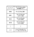
図4に示すテーブルは、DCIに含まれるビットマップ情報とミューティングパターンとが関連づけられたものであり、ビットマップ”00000”が「ミューティングなし」であり、ビットマップ”00001”が「サービングセルのシフト+1のみ」であり、ビットマップ”00010”が「サービングセルのシフト+2のみ」であり、ビットマップ”00100”が「サービングセルのシフト+3のみ」であり、ビットマップ”11111”が「サービングセルのシフト+1/+2/+3/+4/+5」である。このビットマップは、図5に示すサブキャリア位置を示している。図5においては、サービングセルがセルID#0のミューティングパターンを表し、「サービングセルのシフト+1」がセルID#1のミューティングパターンを表し、「サービングセルのシフト+2」がセルID#2のミューティングパターンを表し、「サービングセルのシフト+3」がセルID#3のミューティングパターンを表している。 The table shown in FIG. 4 is obtained by associating the bitmap information included in the DCI with the muting pattern. The bitmap “00000” is “no muting” and the bitmap “00001” is “serving cell. Bitmap “00010” is “Serving cell shift + 2 only”, Bitmap “00100” is “Serving cell shift + 3 only”, and Bitmap “11111” is “Serving cell shift + 1”. / + 2 / + 3 / + 4 / + 5 ". This bitmap shows the subcarrier positions shown in FIG. In FIG. 5, the serving cell represents the muting pattern of
なお、図4に示すテーブルは一例であり、これに限定されない。また、図4及び図5は、1アンテナの場合について示しているが、この方法は2アンテナ以上の場合にも適用することができる。 The table shown in FIG. 4 is an example, and the present invention is not limited to this. 4 and 5 show the case of one antenna, this method can also be applied to the case of two or more antennas.
(第1方法−2)
この方法は、サブキャリア位置を示すビットマップをCRS多重パターンとして通知する方法である。この方法においては、ビットマップ情報をDCI(Downlink Control Information)に含めてダイナミックに通知する。移動端末装置は、図6に示すテーブル(DCIに含まれるビットマップ情報とCRS多重パターンとが関連づけられたテーブル)を持っており、DCIで通知されたビットマップ情報からCRS多重パターンを認識して、CRS多重位置以外のリソースを用いてデータ信号を復調する。(First method-2)
This method is a method of notifying a bit map indicating a subcarrier position as a CRS multiplex pattern. In this method, bitmap information is included in DCI (Downlink Control Information) and dynamically notified. The mobile terminal apparatus has a table shown in FIG. 6 (a table in which bitmap information included in DCI and a CRS multiplexing pattern are associated), and recognizes the CRS multiplexing pattern from the bitmap information notified by DCI. The data signal is demodulated using resources other than the CRS multiplexing position.
図6に示すテーブルは、DCIに含まれるビットマップ情報とCRS多重パターンとが関連づけられたものであり、ビットマップ”00000”が「サービングセルと同一」であり、ビットマップ”00001”が「サービングセルのシフト+1のみ」であり、ビットマップ”00010”が「サービングセルのシフト+2のみ」であり、ビットマップ”00100”が「サービングセルのシフト+3のみ」であり、ビットマップ”11111”が「サービングセルのシフト+1/+2/+3/+4/+5」である。このビットマップは、図7に示すサブキャリア位置を示している。図7においては、サービングセルがセルID#0のCRS多重パターンを表し、「サービングセルのシフト+1」がセルID#1のCRS多重パターンを表し、「サービングセルのシフト+2」がセルID#2のCRS多重パターンを表し、「サービングセルのシフト+3」がセルID#3のCRS多重パターンを表している。 The table shown in FIG. 6 is obtained by associating the bitmap information included in the DCI with the CRS multiplexing pattern. The bitmap “00000” is “same as the serving cell”, and the bitmap “00001” is “the serving cell. Bitmap “00010” is “Serving cell shift + 2 only”, Bitmap “00100” is “Serving cell shift + 3 only”, and Bitmap “11111” is “Serving cell shift + 1”. / + 2 / + 3 / + 4 / + 5 ". This bitmap shows the subcarrier positions shown in FIG. In FIG. 7, the serving cell represents the CRS multiplexing pattern of the
なお、図6に示すテーブルは一例であり、これに限定されない。また、図6及び図7は、1アンテナの場合について示しているが、この方法は2アンテナ以上の場合にも適用することができる。 The table shown in FIG. 6 is an example, and the present invention is not limited to this. 6 and 7 show the case of one antenna, this method can be applied to the case of two or more antennas.
(第2方法−1)
この方法は、ミューティングパターンを示す下り制御情報をミューティングパターンとして通知する方法である。この方法においては、ミューティングパターンを示すビットをDCIに含めてダイナミックに通知する。この場合、下り制御情報とミューティングパターンとが関連づけられている。移動端末装置は、図8に示すテーブル(DCIに含まれるビットとミューティングパターンとが関連づけられたテーブル)を持っており、DCIで通知されたビットからミューティングパターンを認識して、ミューティングパターン以外のリソースを用いてデータ信号を復調する。(Second method-1)
This method is a method of notifying downlink control information indicating a muting pattern as a muting pattern. In this method, a bit indicating a muting pattern is dynamically included in DCI. In this case, the downlink control information and the muting pattern are associated with each other. The mobile terminal apparatus has the table shown in FIG. 8 (a table in which bits included in DCI and muting patterns are associated), recognizes the muting pattern from the bits notified by DCI, and muting pattern. The data signal is demodulated using resources other than.
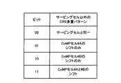
図8に示すテーブルは、DCIに含まれるビットとミューティングパターンとが関連づけられたものであり、ビット”00”が「ミューティングなし」であり、ビット”01”が「サービングセルのシフト+1のみ」であり、ビット”10”が「サービングセルのシフト+2のみ」であり、ビット”11”が「サービングセルのシフト+1/+2」である。例えば、ビット”01”は図2Aのミューティングパターンを表し、ビット”11”は図9のミューティングパターンを表している。なお、図8に示すテーブルは一例であり、これに限定されない。 The table shown in FIG. 8 associates the bit included in the DCI with the muting pattern, the bit “00” is “no muting”, and the bit “01” is “serving cell shift + 1 only”. Bit “10” is “serving cell shift +2 only” and bit “11” is “serving cell shift + 1 / + 2”. For example, bit “01” represents the muting pattern of FIG. 2A, and bit “11” represents the muting pattern of FIG. The table shown in FIG. 8 is an example, and the present invention is not limited to this.
(第2方法−2)
この方法は、CRS多重パターンを示す下り制御情報をCRS多重パターンとして通知する方法である。この方法においては、CRS多重パターンを示すビットをDCIに含めてダイナミックに通知する。この場合、下り制御情報とCRS多重パターンとが関連づけられている。移動端末装置は、図10に示すテーブル(DCIに含まれるビットとCRS多重パターンとが関連づけられたテーブル)を持っており、DCIで通知されたビットからCRS多重パターンを認識して、CRS多重位置以外のリソースを用いてデータ信号を復調する。(Second method-2)
This method is a method of notifying downlink control information indicating a CRS multiplexing pattern as a CRS multiplexing pattern. In this method, bits indicating a CRS multiplexing pattern are included in DCI and dynamically notified. In this case, the downlink control information and the CRS multiplexing pattern are associated with each other. The mobile terminal apparatus has the table shown in FIG. 10 (a table in which bits included in DCI and CRS multiplexing patterns are associated), recognizes the CRS multiplexing pattern from the bits notified by DCI, and determines the CRS multiplexing position. The data signal is demodulated using resources other than.
図10に示すテーブルは、DCIに含まれるビットとCRS多重パターンとが関連づけられたものであり、ビット”000”が「サービングセルと同一」であり、ビット”001”が「サービングセルのシフト+1のみ」であり、ビット”010”が「サービングセルのシフト+2のみ」であり、ビット”011”が「サービングセルのシフト+3のみ」であり、ビット”100”が「サービングセルのシフト+4のみ」であり、ビット”101”が「サービングセルのシフト+5のみ」である。例えば、ビット”001”は図3BのCRS多重パターンを表し、ビット”010”は図11のCRS多重パターンを表している。なお、図10に示すテーブルは一例であり、これに限定されない。 In the table shown in FIG. 10, the bits included in the DCI are associated with the CRS multiplexing pattern, the bit “000” is “same as the serving cell”, and the bit “001” is “serving cell shift + 1 only”. Bit “010” is “serving cell shift +2 only”, bit “011” is “serving cell shift +3 only”, bit “100” is “serving cell shift +4 only”, bit “ 101 "is" serving cell shift +5 only ". For example, the bit “001” represents the CRS multiplexing pattern of FIG. 3B, and the bit “010” represents the CRS multiplexing pattern of FIG. Note that the table shown in FIG. 10 is an example, and the present invention is not limited to this.
(第3方法−1)
この方法は、ハイヤレイヤシグナリングにより送信されるCoMPセルのセル識別情報と、このCoMPセルの情報(ミューティングするセルに関する情報)に対応する下り制御情報とでミューティングパターンを通知する方法である。この場合、下り制御情報とCoMPセルの情報とが関連づけられている。移動端末装置は、図12に示すテーブル(DCIに含まれるビットとCoMPセルの情報とが関連づけられたテーブル)を持っており、DCIで通知されたビットからCoMPセルの情報と、ハイヤレイヤシグナリングで通知されたCoMPセルのセル識別情報(セルID)とからミューティングパターンを求め、ミューティングパターン以外のリソースを用いてデータ信号を復調する。(Third method-1)
This method is a method of notifying a muting pattern by cell identification information of a CoMP cell transmitted by higher layer signaling and downlink control information corresponding to the information of the CoMP cell (information on a cell to be muted). In this case, downlink control information and CoMP cell information are associated with each other. The mobile terminal apparatus has a table shown in FIG. 12 (a table in which bits included in DCI and CoMP cell information are associated), and information on CoMP cells and higher layer signaling are transmitted from bits notified by DCI. A muting pattern is obtained from the notified cell identification information (cell ID) of the CoMP cell, and a data signal is demodulated using resources other than the muting pattern.
この方法においては、無線基地局装置は、ハイヤレイヤシグナリングでCoMPセル(CoMP送信を適用する可能性のあるセル)のセルIDを移動端末装置に通知する。例えば、無線基地局装置は、CoMPセルがセル#A、セル#Bである場合、セル#AのセルID7番とセル#BのセルID8番を移動端末装置に通知する。一方、無線基地局装置は、DCIでCoMPセルの情報を移動端末装置に通知する。例えば、無線基地局装置は、CoMPセルの情報として、「CoMPセル#Bのシフトのみ」を示すDCIのビット”10”を移動端末装置に通知する。移動端末装置においては、セルID番号とCoMPセルの情報とからミューティングパターンを求める。すなわち、セル#BのセルID番号のMod6を計算してシフト量2を算出し(剰余演算)、これによりミューティングパターンを求める(サービングセルのシフト+2)。なお、図12に示すテーブルやセルID番号は一例であり、これに限定されない。 In this method, the radio base station apparatus notifies the mobile terminal apparatus of the cell ID of a CoMP cell (a cell to which CoMP transmission may be applied) by higher layer signaling. For example, when the CoMP cells are cell #A and cell #B, the radio base station apparatus notifies the mobile terminal apparatus of cell ID No. 7 of cell #A and cell ID No. 8 of cell #B. On the other hand, the radio base station apparatus notifies CoMP cell information to the mobile terminal apparatus by DCI. For example, the radio base station apparatus notifies the mobile terminal apparatus of DCI bit “10” indicating “only shift of CoMP cell #B” as CoMP cell information. In the mobile terminal device, a muting pattern is obtained from the cell ID number and the information of the CoMP cell. That is, Mod 6 of the cell ID number of cell #B is calculated to calculate a shift amount 2 (residue calculation), thereby obtaining a muting pattern (serving cell shift + 2). Note that the table and cell ID number shown in FIG. 12 are examples, and the present invention is not limited to this.
(第3方法−2)
この方法は、ハイヤレイヤシグナリングにより送信されるCoMPセルのセル識別情報と、このCoMPセルの情報(CRS多重パターンのセルに関する情報)に対応する下り制御情報とでCRS多重パターンを通知する方法である。この場合、下り制御情報とCoMPセルの情報とが関連づけられている。移動端末装置は、図13に示すテーブル(DCIに含まれるビットとCoMPセルの情報とが関連づけられたテーブル)を持っており、DCIで通知されたビットからCoMPセルの情報と、ハイヤレイヤシグナリングで通知されたCoMPセルのセル識別情報(セルID)とからCRS多重パターンを求め、CRS多重位置以外のリソースを用いてデータ信号を復調する。(Third method-2)
This method is a method of notifying the CRS multiplexing pattern by the cell identification information of the CoMP cell transmitted by higher layer signaling and the downlink control information corresponding to the information of the CoMP cell (information on the cell of the CRS multiplexing pattern). . In this case, downlink control information and CoMP cell information are associated with each other. The mobile terminal apparatus has a table shown in FIG. 13 (a table in which bits included in DCI are associated with CoMP cell information), and information on CoMP cells and higher layer signaling are transmitted from bits notified by DCI. A CRS multiplexing pattern is obtained from the notified cell identification information (cell ID) of the CoMP cell, and a data signal is demodulated using resources other than the CRS multiplexing position.
この方法においては、無線基地局装置は、ハイヤレイヤシグナリングでCoMPセル(CoMP送信を適用する可能性のあるセル)のセルIDを移動端末装置に通知する。例えば、無線基地局装置は、CoMPセルがセル#A、セル#Bである場合、セル#AのセルID7番とセル#BのセルID8番を移動端末装置に通知する。一方、無線基地局装置は、DCIでCoMPセルの情報を移動端末装置に通知する。例えば、無線基地局装置は、CoMPセルの情報として、「CoMPセル#Bのシフトのみ」を示すDCIのビット”10”を移動端末装置に通知する。移動端末装置においては、セルID番号とCoMPセルの情報とからCRS多重パターンを求める。すなわち、セル#BのセルID番号のMod6を計算してシフト量2を算出し(剰余演算)、これによりCRS多重パターンを求める(サービングセルのシフト+2)。なお、図13に示すテーブルやセルID番号は一例であり、これに限定されない。 In this method, the radio base station apparatus notifies the mobile terminal apparatus of the cell ID of a CoMP cell (a cell to which CoMP transmission may be applied) by higher layer signaling. For example, when the CoMP cells are cell #A and cell #B, the radio base station apparatus notifies the mobile terminal apparatus of cell ID No. 7 of cell #A and cell ID No. 8 of cell #B. On the other hand, the radio base station apparatus notifies CoMP cell information to the mobile terminal apparatus by DCI. For example, the radio base station apparatus notifies the mobile terminal apparatus of DCI bit “10” indicating “only shift of CoMP cell #B” as CoMP cell information. In the mobile terminal apparatus, a CRS multiplexing pattern is obtained from the cell ID number and CoMP cell information. That is, Mod 6 of the cell ID number of cell #B is calculated to calculate a shift amount 2 (residue calculation), thereby obtaining a CRS multiplexing pattern (serving cell shift + 2). Note that the table and the cell ID number shown in FIG. 13 are examples, and the present invention is not limited to this.
(第4方法−1)
この方法は、ミューティングパターンをハイヤレイヤシグナリング(例えば、RRCシグナリング)で通知する方法である。この方法においては、ミューティングパターンをセミスタティックに通知する。ハイヤレイヤシグナリングで通知するミューティングパターンは、上記第1方法で使用するビットマップ情報でも良く、上記第2方法で使用するビット情報でも良い。(Fourth Method-1)
This method is a method of notifying the muting pattern by higher layer signaling (for example, RRC signaling). In this method, the muting pattern is notified semi-statically. The muting pattern notified by higher layer signaling may be bitmap information used in the first method or bit information used in the second method.
この方法においては、ミューティングパターンをスタティックにしても良い。ミューティングパターンをスタティックにする場合においては、図15に示すように、PDSCH領域でCRSが多重されるシンボル(X)について、CoMP受信する移動端末装置に対してデータ信号を割り当てない。すなわち、CoMP受信する移動端末装置に対しては、CoMPセルでCRSが多重されるすべてのシンボル(X)のパターンがミューティングパターンとなる。 In this method, the muting pattern may be static. When the muting pattern is static, as shown in FIG. 15, no data signal is assigned to the mobile terminal apparatus that receives CoMP for the symbol (X) in which the CRS is multiplexed in the PDSCH region. That is, for a mobile terminal device that receives CoMP, the pattern of all symbols (X) in which CRS is multiplexed in the CoMP cell is a muting pattern.
(第4方法−2)
この方法は、CRS多重パターンをハイヤレイヤシグナリング(例えば、RRCシグナリング)で通知する方法である。この方法においては、CRS多重パターンをセミスタティックに通知する。ハイヤレイヤシグナリングで通知するCRS多重パターンは、上記第1方法−2で使用するビットマップ情報でも良く、上記第2方法−2で使用するビット情報でも良い。(Fourth method-2)
In this method, the CRS multiplexing pattern is notified by higher layer signaling (for example, RRC signaling). In this method, the CRS multiplexing pattern is notified semi-statically. The CRS multiplexing pattern notified by higher layer signaling may be bitmap information used in the first method-2 or bit information used in the second method-2.
この方法においては、CRS多重パターンをスタティックにしても良い。CRS多重パターンをスタティックにする場合においては、図14に示すように、PDSCH領域でCRSが多重されるシンボル(X)について、CoMP受信する移動端末装置に対してデータ信号を割り当てない。すなわち、CoMP受信する移動端末装置に対しては、CoMPセルでCRSが多重されるすべてのシンボル(X)のパターンがCRS多重パターンとなる。 In this method, the CRS multiple pattern may be static. When the CRS multiplexing pattern is static, as shown in FIG. 14, no data signal is assigned to the mobile terminal apparatus that receives CoMP for the symbol (X) in which the CRS is multiplexed in the PDSCH region. That is, for the mobile terminal apparatus that receives CoMP, the pattern of all symbols (X) in which CRS is multiplexed in the CoMP cell is the CRS multiplexing pattern.
CRSと同様に、PDCCHは、それぞれセル毎に異なる位置に多重されることがあるので、JP−CoMPを適用するときに、移動端末装置において、正確にデータ信号を復調することができないことが考えられる。 Similar to CRS, PDCCH may be multiplexed at different positions for each cell. Therefore, when applying JP-CoMP, it is considered that the data signal cannot be demodulated accurately in the mobile terminal apparatus. It is done.
PDCCH信号は、サブフレームの先頭1OFDMシンボルから3OFDMシンボルに多重されるので、図15に示すように、サービングセル(セル#A:図15A)のPDCCHシンボル長と、隣接セル(セル#B:図15B)のPDCCHシンボル長が異なることが考えられる。この場合において、JP−CoMPを適用すると、PDCCHシンボル長が長いセルに合わせてCoMP受信する移動端末装置にデータ送信を行う必要がある。例えば、JP−CoMPを適用する場合において、図15に示すように、サービングセルのPDCCH長が隣接セルのPDCCH長よりも短い場合には、CoMP受信する移動端末装置に対して、サービングセル以外のセルのPDCCH長を通知する必要がある。このため、サービングセルの無線基地局装置は、サービングセル以外のセルのPDCCH長を復調用情報として移動端末装置に通知する。なお、移動端末装置においては、PDCCH長の情報を受けたときに、PDCCH長+1OFDMシンボルからPDSCHを多重することになるので、PDCCH長の代わりに、PDSCHの多重開始位置を復調用情報としても良い。 Since the PDCCH signal is multiplexed from the first OFDM symbol to 3 OFDM symbols in the subframe, as shown in FIG. 15, the PDCCH symbol length of the serving cell (cell #A: FIG. 15A) and the adjacent cell (cell #B: FIG. 15B). ) May have different PDCCH symbol lengths. In this case, when JP-CoMP is applied, it is necessary to perform data transmission to a mobile terminal apparatus that performs CoMP reception in accordance with a cell having a long PDCCH symbol length. For example, in the case of applying JP-CoMP, as shown in FIG. 15, when the PDCCH length of the serving cell is shorter than the PDCCH length of the neighboring cell, the mobile terminal apparatus that receives CoMP is notified of cells other than the serving cell. It is necessary to notify the PDCCH length. For this reason, the radio base station apparatus of the serving cell notifies the mobile terminal apparatus of the PDCCH length of cells other than the serving cell as demodulation information. In addition, in the mobile terminal apparatus, when receiving the information on the PDCCH length, the PDSCH is multiplexed from the PDCCH length + 1 OFDM symbol. Therefore, the PDSCH multiplexing start position may be used as demodulation information instead of the PDCCH length. .
このPDSCHの多重開始位置の情報の通知方法については、以下の2つ(第5方法、第6方法)が挙げられる。 There are the following two methods (fifth method and sixth method) for reporting the PDSCH multiplexing start position information.
(第5方法)
この方法は、PDSCHの多重開始位置を示す下り制御情報を通知する方法である。この方法においては、PDSCHの多重開始位置を示すビットをDCIに含めてダイナミックに通知する。この場合、下り制御情報とPDSCHの多重開始位置とが関連づけられている。移動端末装置は、図16に示すテーブル(DCIに含まれるビットとPDSCHの多重開始位置とが関連づけられたテーブル)を持っており、DCIで通知されたビットからPDSCHの多重開始位置を認識して、その多重開始位置からデータ信号を復調する。(Fifth method)
This method is a method of notifying downlink control information indicating the multiplexing start position of PDSCH. In this method, a bit indicating the multiplexing start position of PDSCH is included in DCI and dynamically notified. In this case, downlink control information and PDSCH multiplexing start position are associated with each other. The mobile terminal apparatus has the table shown in FIG. 16 (a table in which the bits included in DCI and the multiplexing start position of PDSCH are associated), and recognizes the multiplexing start position of PDSCH from the bits notified by DCI. The data signal is demodulated from the multiplexing start position.
図16に示すテーブルは、DCIに含まれるビットとPDSCHの多重開始位置とが関連づけられたものであり、ビット”00”が「1シンボル目」であり、ビット”01”が「2シンボル目」であり、ビット”10”が「3シンボル目」であり、ビット”11”が「4シンボル目」である。例えば、ビット”10”は図17のPDSCHの多重開始位置(3シンボル目)を表している。なお、図16に示すテーブルは一例であり、これに限定されない。 The table shown in FIG. 16 associates bits included in DCI with the PDSCH multiplexing start position, and bit “00” is “first symbol” and bit “01” is “second symbol”. Bit “10” is the “third symbol”, and bit “11” is the “fourth symbol”. For example, bit “10” represents the multiplexing start position (third symbol) of PDSCH in FIG. Note that the table shown in FIG. 16 is an example, and the present invention is not limited to this.
(第6方法)
この方法は、PDSCHの多重開始位置をハイヤレイヤシグナリング(例えば、RRCシグナリング)で通知する方法である。この方法においては、PDSCHの多重開始位置をセミスタティックに通知する。ハイヤレイヤシグナリングで通知するPDSCHの多重開始位置は、上記第5方法で使用するビット情報でも良い。(Sixth method)
This method is a method of notifying the PDSCH multiplexing start position by higher layer signaling (for example, RRC signaling). In this method, the PDSCH multiplexing start position is notified semi-statically. The PDSCH multiplexing start position notified by higher layer signaling may be bit information used in the fifth method.
この方法においては、PDSCHの多重開始位置をスタティックにしても良い。PDSCHの多重開始位置をスタティックにする場合においては、多重開始位置を常に固定する(例えば、4シンボル目)。 In this method, the PDSCH multiplexing start position may be static. When the PDSCH multiplexing start position is static, the multiplexing start position is always fixed (for example, the fourth symbol).
なお、PDSCHの多重開始位置を通知する場合については、無線基地局装置は、サービングセルのPDCCH長が隣接セルのPDCCH長よりも短いかどうかを判断し、サービングセルのPDCCH長が隣接セルのPDCCH長よりも短いときに、隣接セルのPDCCH長を考慮してPDSCHの多重開始位置を決定して、その多重開始位置を移動端末装置に通知する。例えば、無線基地局装置は、サービングセルのPDCCH長が隣接セルのPDCCH長よりも短いときに、隣接セルのPDCCH長のうち最も長いPDCCH長+1シンボルをPDSCHの多重開始位置とする。したがって、PDCCH長が最大3シンボルの場合には、PDSCHの多重開始位置は最大4シンボルとなる。 In the case of notifying the PDSCH multiplexing start position, the radio base station apparatus determines whether the PDCCH length of the serving cell is shorter than the PDCCH length of the neighboring cell, and the PDCCH length of the serving cell is larger than the PDCCH length of the neighboring cell. Is shorter, the PDSCH multiplexing start position is determined in consideration of the PDCCH length of the adjacent cell, and the multiplexing start position is notified to the mobile terminal apparatus. For example, when the PDCCH length of the serving cell is shorter than the PDCCH length of the neighboring cell, the radio base station apparatus sets the longest PDCCH length + 1 symbol among the PDCCH lengths of the neighboring cell as the PDSCH multiplexing start position. Therefore, when the PDCCH length is a maximum of 3 symbols, the PDSCH multiplexing start position is a maximum of 4 symbols.
上述したように、復調用情報とは、移動端末装置におけるデータ信号の復調をサポートするための情報であり、CRSとデータ信号の衝突回避を目的とする場合には、サービングセル以外のセルのCRSの多重位置に関する情報である。また、PDCCHのシンボル長の違いを許容することを目的とする場合には、復調用情報とは、PDCCHのシンボル長又はPDSCHの多重開始位置に関する情報である。なお、両方を目的とする場合に、復調用情報が、サービングセル以外のセルのCRSの多重位置に関する情報、及びPDCCHのシンボル長又はPDSCHの多重開始位置に関する情報であることはいうまでもない。 As described above, the demodulation information is information for supporting the demodulation of the data signal in the mobile terminal apparatus. For the purpose of avoiding collision between the CRS and the data signal, the CRS of the cells other than the serving cell is used. Information on multiple positions. In addition, when the purpose is to allow a difference in PDCCH symbol length, the demodulation information is information on the PDCCH symbol length or the PDSCH multiplexing start position. Needless to say, for both purposes, the demodulation information is information on CRS multiplexing positions of cells other than the serving cell, and information on the PDCCH symbol length or PDSCH multiplexing start position.
このように、本発明においては、協調マルチポイント送信を適用する際に、移動端末装置におけるデータ信号の復調用情報を協調マルチポイント受信する移動端末装置に送信し、移動端末装置で、復調用情報を用いて協調マルチポイント受信したデータ信号を復調するので、協調マルチポイント送信、特に、JP−CoMPを適用する場合に、移動端末装置で正確にデータ信号を復調させることができる。 Thus, in the present invention, when cooperative multipoint transmission is applied, data signal demodulation information in the mobile terminal apparatus is transmitted to the mobile terminal apparatus that receives cooperative multipoint reception, and the mobile terminal apparatus uses the demodulation information. Is used to demodulate the data signal received by cooperative multipoint, and therefore, when cooperative multipoint transmission, particularly, JP-CoMP is applied, the data signal can be accurately demodulated by the mobile terminal apparatus.
以下、本発明の実施の形態について、添付図面を参照して詳細に説明する。ここでは、LTE−Aシステムに対応する無線基地局装置及び移動端末装置を用いる場合について説明する。 Hereinafter, embodiments of the present invention will be described in detail with reference to the accompanying drawings. Here, a case where a radio base station apparatus and a mobile terminal apparatus corresponding to the LTE-A system are used will be described.
図18を参照しながら、本発明の一実施の形態に係る移動端末装置(UE:User Equipment)10及び無線基地局装置(eNodeB)20を有する無線通信システム1について説明する。図18は、本発明に係る移動端末装置10及び無線基地局装置20を有する無線通信システム1の構成を説明するための図である。なお、図18に示す無線通信システム1は、例えば、LTEシステム又はSUPER 3Gが包含されるシステムである。また、この移動通信システム1は、IMT−Advancedと呼ばれても良いし、4Gと呼ばれても良い。 A
図18に示すように、無線通信システム1は、無線基地局装置20A,20Bと、この無線基地局装置20A,20Bと通信する複数の移動端末装置10A,10Bとを含んで構成されている。無線基地局装置20A,20Bは、それぞれ上位局装置30と接続され、この上位局装置30は、コアネットワーク40と接続される。移動端末装置10A,10Bは、セルC1において無線基地局装置20Aと通信を行っており、セルC2において無線基地局装置20Bと通信を行っている。なお、上位局装置30には、例えば、アクセスゲートウェイ装置、無線ネットワークコントローラ(RNC)、モビリティマネジメントエンティティ(MME)などが含まれるが、これに限定されるものではない。 As shown in FIG. 18, the
各移動端末装置(10A,10B)は、同一の構成、機能、状態を有するので、以下においては、特段の断りがない限り移動端末装置10として説明を進める。また、説明の便宜上、無線基地局装置20A,20Bと無線通信するのは移動端末装置10であるものとして説明するが、より一般的には移動端末装置も固定端末装置も含むユーザ装置(UE)でよい。 Since each mobile terminal device (10A, 10B) has the same configuration, function, and state, the following description will be given as the mobile
無線通信システム1においては、無線アクセス方式として、下りリンクについてはOFDMA(直交周波数分割多元接続)が、上りリンクについてはSC−FDMA(シングルキャリア−周波数分割多元接続)が適用される。OFDMAは、周波数帯域を複数の狭い周波数帯域(サブキャリア)に分割し、各サブキャリアにデータをマッピングして通信を行うマルチキャリア伝送方式である。SC−FDMAは、システム帯域を端末毎に1つ又は連続したリソースブロックからなる帯域に分割し、複数の端末が互いに異なる帯域を用いることで、端末間の干渉を低減するシングルキャリア伝送方式である。 In the
ここで、LTEシステムにおける通信チャネルについて説明する。下りリンクの通信チャネルは、移動端末装置10A,10Bで共有される下りデータチャネルとしてのPDSCHと、下りL1/L2制御チャネル(PDCCH、PCFICH、PHICH)とを有する。PDSCHにより、送信データ及び上位制御情報が伝送される。PDCCHにより、PDSCHおよびPUSCHのスケジューリング情報等が伝送される。PCFICH(Physical Control Format Indicator Channel)により、PDCCHに用いるOFDMシンボル数が伝送される。PHICH(Physical Hybrid-ARQ Indicator Channel)により、PUSCHに対するHARQのACK/NACKが伝送される。 Here, a communication channel in the LTE system will be described. The downlink communication channel includes PDSCH as a downlink data channel shared by the mobile
上りリンクの通信チャネルは、各移動端末装置で共有される上りデータチャネルとしてのPUSCH(Physical Uplink Shared Channel)と、上りリンクの制御チャネルであるPUCCH(Physical Uplink Control Channel)とを有する。このPUSCHにより、送信データや上位制御情報が伝送される。また、PUCCHにより、下りリンクのチャネル品質情報(CQI)、ACK/NACKなどが伝送される。 The uplink communication channel includes a PUSCH (Physical Uplink Shared Channel) as an uplink data channel shared by each mobile terminal apparatus and a PUCCH (Physical Uplink Control Channel) which is an uplink control channel. Transmission data and higher control information are transmitted by this PUSCH. Further, downlink channel quality information (CQI), ACK / NACK, and the like are transmitted by PUCCH.
図19を参照しながら、本実施の形態に係る無線基地局装置の全体構成について説明する。なお、無線基地局装置20A,20Bは、同様な構成であるため、無線基地局装置20として説明する。また、移動端末装置10A,10Bも、同様な構成であるため、移動端末装置10として説明する。無線基地局装置20は、送受信アンテナ201と、アンプ部202と、送受信部(通知部)203と、ベースバンド信号処理部204と、呼処理部205と、伝送路インターフェース206とを備えている。下りリンクにより無線基地局装置20から移動端末装置に送信される送信データは、上位局装置30から伝送路インターフェース206を介してベースバンド信号処理部204に入力される。 The overall configuration of the radio base station apparatus according to the present embodiment will be described with reference to FIG. Note that the radio
ベースバンド信号処理部204において、下りデータチャネルの信号は、PDCPレイヤの処理、送信データの分割・結合、RLC(Radio Link Control)再送制御の送信処理などのRLCレイヤの送信処理、MAC(Medium Access Control)再送制御、例えば、HARQの送信処理、スケジューリング、伝送フォーマット選択、チャネル符号化、逆高速フーリエ変換(IFFT)処理、プリコーディング処理が行われる。また、下りリンク制御チャネルである物理下りリンク制御チャネルの信号に関しても、チャネル符号化や逆高速フーリエ変換などの送信処理が行われる。 In the baseband
また、ベースバンド信号処理部204は、報知チャネルにより、同一セルに接続する移動端末装置10に対して、各移動端末装置10が無線基地局装置20との無線通信するための制御情報を通知する。当該セルにおける通信のための情報には、例えば、上りリンク又は下りリンクにおけるシステム帯域幅や、PRACH(Physical Random Access Channel)におけるランダムアクセスプリアンブルの信号を生成するためのルート系列の識別情報(Root Sequence Index)などが含まれる。 Further, the baseband
送受信部203は、ベースバンド信号処理部204から出力されたベースバンド信号を無線周波数帯に変換する。アンプ部202は周波数変換された無線周波数信号を増幅して送受信アンテナ201へ出力する。なお、送受信部203は、複数セル間の位相差の情報及びPMIを含む上りリンク信号を受信する受信部、及び送信信号を協調マルチポイント送信する送信部を構成する。 The transmission /
一方、上りリンクにより移動端末装置10から無線基地局装置20に送信される信号については、送受信アンテナ201で受信された無線周波数信号がアンプ部202で増幅され、送受信部203で周波数変換されてベースバンド信号に変換され、ベースバンド信号処理部204に入力される。 On the other hand, for a signal transmitted from the mobile
ベースバンド信号処理部204は、上りリンクで受信したベースバンド信号に含まれる送信データに対して、FFT処理、IDFT処理、誤り訂正復号、MAC再送制御の受信処理、RLCレイヤ、PDCPレイヤの受信処理を行う。復号された信号は伝送路インターフェース206を介して上位局装置30に転送される。 The baseband
呼処理部205は、通信チャネルの設定や解放等の呼処理や、無線基地局装置20の状態管理や、無線リソースの管理を行う。 The
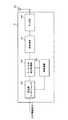
図20を参照して、無線基地局装置20の機能ブロックについて説明する。図20の各機能ブロックは、主にベースバンド処理部の処理内容である。また、図20に示す機能ブロックは、本発明を説明するために簡略化したものであり、ベースバンド処理部において通常備える構成は備えるものとする。 With reference to FIG. 20, the functional blocks of the radio
図20に示すように、無線基地局装置20は、CRS割当部211と、DM−RS割当部212と、CSI−RS割当部213と、復調用情報生成部214と、下り制御信号生成部215と、送受信部203とを有している。この無線基地局装置20は、CoMP送信を適用する際に、移動端末装置におけるデータ信号の復調用情報を生成し、この復調用情報をCoMP受信する移動端末装置に送信する。 As illustrated in FIG. 20, the radio
CRS割当部211は、各サブフレームのリソーブロックにおけるCRS送信用リソースにCRSを配置する。CRSが他の制御信号と重ならないようにCRS配置位置を定めたCRS配置パターンにしたがってリソーブロック上の該当リソースエレメントにCRSが配置される。 The
DM−RS(Demodulation‐Reference Signal)割当部212は、各サブフレームのリソーブロックにおけるDM−RS送信用リソースにDM−RSを配置する。CSI−RS(Channel State Information‐Reference Signal)Demodulation‐Reference Signal)割当部213は、CSI−RS送信周期(例えば、10ms又は8ms)で無線フレーム内の該当サブフレームにCSI−RSを配置する。 A DM-RS (Demodulation-Reference Signal)
復調用情報生成部214は、移動端末装置におけるデータ信号の復調用情報を生成し、その復調用情報を下り制御信号215に出力する。この復調用情報とは、上述したように、PDSCHミューティングパターン、CRS多重パターン、PDSCHの開始位置の情報をいう。復調用情報生成部214は、復調用情報として、PDSCHミューティングパターンやCRS多重パターン(パターン情報)を生成しても良く、PDSCHミューティングパターンやCRS多重パターン(パターン情報)に関するサブキャリア位置を示すビットマップ情報を生成しても良く、PDSCHミューティングパターンやCRS多重パターン(パターン情報)に関するCoMPセルの情報(ミューティングするセル又はCRS多重パターンのセルに関する情報)を生成しても良い。したがって、復調用情報生成部214は、第1方法−1においては、復調用情報としてPDSCHミューティングパターンに関するサブキャリア位置を示すビットマップ情報を生成し、第2方法−1においては、復調用情報としてPDSCHミューティングパターンを生成し、第3方法−1においては、PDSCHミューティングパターンに関するCoMPセルの情報を生成する。また、復調用情報生成部214は、第1方法−2においては、復調用情報としてCRS多重パターンに関するサブキャリア位置を示すビットマップ情報を生成し、第2方法−2においては、復調用情報としてCRS多重パターンを生成し、第3方法−2においては、CRS多重パターンに関するCoMPセルの情報を生成する。また、復調用情報生成部214は、第5方法においては、復調用情報としてPDSCHの多重開始位置情報を生成する。 The demodulation
下り制御信号生成部215は、PDSCHミューティングパターン、CRS多重パターン、PDSCHの開始位置の情報をDCIに含めて下り制御信号を生成する。下り制御信号生成部215は、第1方法−1においては、PDSCHミューティングパターンに関するサブキャリア位置を示すビットマップをDCIに含めて下り制御信号を生成し、第2方法−1においては、PDSCHミューティングパターンに対応するビットをDCIに含めて下り制御信号を生成し、第3方法−1においては、CoMPセルの情報に対応するビットをDCIに含めて下り制御信号を生成する。また、下り制御信号生成部215は、第1方法−2においては、CRS多重パターンに関するサブキャリア位置を示すビットマップをDCIに含めて下り制御信号を生成し、第2方法−2においては、CRS多重パターンに対応するビットをDCIに含めて下り制御信号を生成し、第3方法−2においては、CoMPセルの情報に対応するビットをDCIに含めて下り制御信号を生成する。また、下り制御信号生成部215は、生成した下り制御信号(PDCCH信号)を送受信部203に出力する。また、下り制御信号生成部215は、第5方法においては、PDSCHの多重開始位置をDCIに含めて下り制御信号を生成する。 The downlink control
送受信部203は、CRS、DM−RS、CSI−RS及び下り制御信号をリソースにマッピングして下りリンク信号として移動端末装置10に送信する。なお、下りリンク信号については、上記信号の他に下りリンク信号として通常送信する信号も含まれる。 The transmission /
無線基地局装置20は、ハイヤレイヤシグナリングで復調用情報を移動端末装置10に送信しても良い。無線基地局装置20は、第3方法−1、第3方法−2においては、復調用情報としてCoMPセルのセルIDを移動端末装置10に送信し、第4方法−1においては、復調用情報としてPDSCHミューティングパターンを移動端末装置に送信し、第4方法−2においては、復調用情報としてCRS多重パターンを移動端末装置に送信する。また、無線基地局装置20は、第6方法においては、復調用情報としてPDSCHの多重開始位置を移動端末装置10に送信する。 The radio
次に、図21を参照しながら、本実施の形態に係る移動端末装置の全体構成について説明する。LTE端末もLTE−A端末もハードウエアの主要部構成は同じであるので、区別せずに説明する。移動端末装置10は、送受信アンテナ101と、アンプ部102と、送受信部(受信部)103と、ベースバンド信号処理部104と、アプリケーション部105とを備えている。この移動端末装置は、CoMP送信を適用する際に、サービングセルからのデータ信号の復調用情報を受信し、復調用情報を用いてCoMP受信したデータ信号を復調する。 Next, the overall configuration of the mobile terminal apparatus according to the present embodiment will be described with reference to FIG. Since the main parts of the hardware of the LTE terminal and the LTE-A terminal are the same, they will be described without distinction. The mobile
下りリンクのデータについては、送受信アンテナ101で受信された無線周波数信号がアンプ部102で増幅され、送受信部103で周波数変換されてベースバンド信号に変換される。このベースバンド信号は、ベースバンド信号処理部104でFFT処理や、誤り訂正復号、再送制御の受信処理等がなされる。この下りリンクのデータの内、下りリンクの送信データは、アプリケーション部105に転送される。アプリケーション部105は、物理レイヤやMACレイヤより上位のレイヤに関する処理等を行う。また、下りリンクのデータの内、報知情報も、アプリケーション部105に転送される。 As for downlink data, a radio frequency signal received by the transmission /
一方、上りリンクの送信データは、アプリケーション部105からベースバンド信号処理部104に入力される。ベースバンド信号処理部104においては、マッピング処理、再送制御(HARQ)の送信処理や、チャネル符号化、DFT処理、IFFT処理を行う。送受信部103は、ベースバンド信号処理部104から出力されたベースバンド信号を無線周波数帯に変換する。その後、アンプ部102で増幅されて送受信アンテナ101より送信される。 On the other hand, uplink transmission data is input from the
図22を参照して、移動端末装置10の機能ブロックについて説明する。図22の各機能ブロックは、主にベースバンド処理部の処理内容である。また、図22に示す機能ブロックは、本発明を説明するために簡略化したものであり、ベースバンド処理部において通常備える構成は備えるものとする。 With reference to FIG. 22, the functional block of the mobile
図22に示すように、移動端末装置10は、送受信部103と、取得部111と、測定部112と、ユーザデータ復調部113とを有している。 As illustrated in FIG. 22, the mobile
送受信部103は、無線基地局装置20から送信された下り制御信号(PDCCH信号)などを受信すると共にデータチャネル信号(PDSCH信号:ユーザデータ)を受信する。送受信部103は、下り制御信号及びハイヤレイヤシグナリングされた制御情報を取得部111に出力する。また、送受信部103は、ユーザデータ及びDM−RSをユーザデータ復調部113に出力すると共に、CRS及びCSI−RSを測定部12に出力する。 The transmission /
取得部111は、送受信部103が受信した下り制御信号を解析して復調用情報を取得する。第1方法−1においては、取得部111は図4に示すテーブルを有している。そして、取得部111は、図4に示すテーブルを参照し、下り制御信号のDCIに含まれるPDSCHミューティングパターンに関するサブキャリア位置を示すビットマップからミューティングパターンを求める。第1方法−2においては、取得部111は図6に示すテーブルを有している。そして、取得部111は、図6に示すテーブルを参照し、下り制御信号のDCIに含まれるCRS多重パターンに関するサブキャリア位置を示すビットマップからCRS多重パターンを求める。 The
第2方法−1においては、取得部111は図8に示すテーブルを有している。そして、取得部111は、図8に示すテーブルを参照し、下り制御信号のDCIに含まれるPDSCHミューティングパターンを求める。第2方法−2においては、取得部111は図10に示すテーブルを有している。そして、取得部111は、図10に示すテーブルを参照し、下り制御信号のDCIに含まれるCRS多重パターンを求める。 In the second method-1, the
第3方法−1においては、取得部111は図12に示すテーブルを有している。そして、取得部111は、図12に示すテーブルを参照し、PDSCHミューティングパターンに関するCoMPセルの情報(ミューティングするセルに関する情報)を取得する。一方、取得部111は、ハイヤレイヤシグナリングで送られたCoMPセルID番号を取得しており、CoMPセルの情報とCoMPセルID番号とからCRSのシフト量を算出し、このシフト量に基づいてPDSCHミューティングパターンを求める。したがって、第3方法−1においては、取得部111は、ミューティングパターンを生成するパターン生成部を構成する。第3方法−2においては、取得部111は図13に示すテーブルを有している。そして、取得部111は、図13に示すテーブルを参照し、CRS多重パターンに関するCoMPセルの情報(CRS多重パターンのセルに関する情報)を取得する。一方、取得部111は、ハイヤレイヤシグナリングで送られたCoMPセルID番号を取得しており、CoMPセルの情報とCoMPセルID番号とからCRSのシフト量を算出し、このシフト量に基づいてCRS多重パターンを求める。したがって、第3方法−2においては、取得部111は、CRS多重パターンを生成するパターン生成部を構成する。 In the third method-1, the
第4方法−1においては、取得部111は、ハイヤレイヤシグナリングで送られたPDSCHミューティングパターンを取得する(セミスタティック)。また、スタティックにPDSCHミューティングパターンを通知する場合には、取得部111は、通信開始時等に無線基地局装置から送られた図14に示すようなPDSCHミューティングパターンを取得する。第4方法−2においては、取得部111は、ハイヤレイヤシグナリングで送られたCRS多重パターンを取得する(セミスタティック)。また、スタティックにCRS多重パターンを通知する場合には、取得部111は、通信開始時等に無線基地局装置から送られた図14に示すようなCRS多重パターンを取得する。 In the fourth method-1, the acquiring
第5方法においては、取得部111は図16に示すテーブルを有している。そして、取得部111は、図16に示すテーブルを参照し、下り制御信号のDCIに含まれるPDSCHの多重開始位置を求める。 In the fifth method, the
第6方法においては、取得部111は、ハイヤレイヤシグナリングで送られたPDSCHの多重開始位置を取得する(セミスタティック)。また、スタティックにPDSCHの多重開始位置を通知する場合には、取得部111は、通信開始時等に無線基地局装置から送られたPDSCHの多重開始位置を取得する。 In the sixth method, the
取得部111は、復調用情報であるPDSCHミューティングパターン、CRS多重パターン、PDSCH多重開始位置情報をユーザデータ復調部113に出力する。測定部112は、リソースブロック上でCSI−RSが多重されているCSI−RSリソースを特定し、CSI−RSを用いてチャネル推定する。
ユーザデータ復調部113は、送受信部103を介して受信したユーザデータを復調する。このとき、ユーザデータ復調部113は、ユーザ固有のDM−RSを用いてユーザデータを復調する。ユーザデータ復調部113は、第1方法〜第4方法においては、取得部111からのパターン情報(PDSCHミューティングパターン、CRS多重パターン)を用い、ミューティングリソースやCRS多重位置を復調処理の対象から外してユーザデータを復調する。また、ユーザデータ復調部113は、第5方法、第6方法においては、取得部111からのPDSCHの多重開始位置を用い、その多重開始位置からユーザデータを復調する。 The user
このように、本発明に係る無線通信システムにおいては、CoMP送信を適用する際に、移動端末装置におけるデータ信号の復調用情報をCoMP受信する移動端末装置に送信し、移動端末装置で、復調用情報を用いてCoMP受信したデータ信号を復調するので、特に、JP−CoMPを適用する場合に、移動端末装置で正確にデータ信号を復調させることができる。 As described above, in the wireless communication system according to the present invention, when applying CoMP transmission, data signal demodulation information in the mobile terminal apparatus is transmitted to the mobile terminal apparatus that receives CoMP, and the mobile terminal apparatus performs demodulation. Since the data signal received by CoMP is demodulated using information, especially when JP-CoMP is applied, the data signal can be accurately demodulated by the mobile terminal apparatus.
次に、本発明に係る無線通信方法について説明する。 Next, a wireless communication method according to the present invention will be described.
(第1方法−1)
無線基地局装置において、復調用情報生成部214で、復調用情報としてPDSCHミューティングパターンに関するサブキャリア位置を示すビットマップ情報を生成する。次いで、下り制御信号生成部215で、PDSCHミューティングパターンに関するサブキャリア位置を示すビットマップをDCIに含めて下り制御信号を生成する。無線基地局装置は、この下り制御信号を移動端末装置に送信する。(First method-1)
In the radio base station apparatus, the demodulation
移動端末装置において、取得部111で図4に示すテーブルを参照し、下り制御信号のDCIに含まれるPDSCHミューティングパターンに関するサブキャリア位置を示すビットマップからミューティングパターンを求める。次いで、ユーザデータ復調部113でミューティングパターンを用いてユーザデータを復調する。 In the mobile terminal apparatus, the
(第1方法−2)
無線基地局装置において、復調用情報生成部214で、復調用情報としてCRS多重パターンに関するサブキャリア位置を示すビットマップ情報を生成する。次いで、下り制御信号生成部215で、CRS多重パターンに関するサブキャリア位置を示すビットマップをDCIに含めて下り制御信号を生成する。無線基地局装置は、この下り制御信号を移動端末装置に送信する。(First method-2)
In the radio base station apparatus, demodulation
移動端末装置において、取得部111で図6に示すテーブルを参照し、下り制御信号のDCIに含まれるCRS多重パターンに関するサブキャリア位置を示すビットマップからCRS多重パターンを求める。次いで、ユーザデータ復調部113でCRS多重パターンを用いてユーザデータを復調する。 In the mobile terminal apparatus, the
(第2方法−1)
無線基地局装置において、復調用情報生成部214で、復調用情報としてPDSCHミューティングパターンを生成する。次いで、下り制御信号生成部215で、PDSCHミューティングパターンを示すビットをDCIに含めて下り制御信号を生成する。無線基地局装置は、この下り制御信号を移動端末装置に送信する。(Second method-1)
In the radio base station apparatus, the demodulation
移動端末装置において、取得部111で図8に示すテーブルを参照し、下り制御信号のDCIに含まれるPDSCHミューティングパターンを求める。次いで、ユーザデータ復調部113でミューティングパターンを用いてユーザデータを復調する。 In the mobile terminal apparatus, the
(第2方法−2)
無線基地局装置において、復調用情報生成部214で、復調用情報としてCRS多重パターンを生成する。次いで、下り制御信号生成部215で、CRS多重パターンを示すビットをDCIに含めて下り制御信号を生成する。無線基地局装置は、この下り制御信号を移動端末装置に送信する。(Second method-2)
In the radio base station apparatus, the demodulation
移動端末装置において、取得部111で図10に示すテーブルを参照し、下り制御信号のDCIに含まれるCRS多重パターンを求める。次いで、ユーザデータ復調部113でCRS多重パターンを用いてユーザデータを復調する。 In the mobile terminal apparatus, the
(第3方法−1)
無線基地局装置において、復調用情報生成部214で、復調用情報としてPDSCHミューティングパターンに関するCoMPセルの情報を生成する。次いで、下り制御信号生成部215で、CoMPセルの情報に対応するビットをDCIに含めて下り制御信号を生成する。無線基地局装置は、この下り制御信号を移動端末装置に送信する。また、無線基地局装置は、ハイヤレイヤシグナリングで復調用情報としてCoMPセルのセルIDを移動端末装置に送信する。(Third method-1)
In the radio base station apparatus, demodulation
移動端末装置において、取得部111で図12に示すテーブルを参照し、PDSCHミューティングパターンに関するCoMPセルの情報(ミューティングするセルに関する情報)を取得する。一方、取得部111は、ハイヤレイヤシグナリングで送られたCoMPセルID番号を取得しており、CoMPセルの情報とCoMPセルID番号とからCRSのシフト量を算出し、このシフト量に基づいてPDSCHミューティングパターンを求める。次いで、ユーザデータ復調部113でミューティングパターンを用いてユーザデータを復調する。 In the mobile terminal apparatus, the
(第3方法−2)
無線基地局装置において、復調用情報生成部214で、復調用情報としてCRS多重パターンに関するCoMPセルの情報を生成する。次いで、下り制御信号生成部215で、CoMPセルの情報に対応するビットをDCIに含めて下り制御信号を生成する。無線基地局装置は、この下り制御信号を移動端末装置に送信する。また、無線基地局装置は、ハイヤレイヤシグナリングで復調用情報としてCoMPセルのセルIDを移動端末装置に送信する。(Third method-2)
In the radio base station apparatus, demodulation
移動端末装置において、取得部111で図13に示すテーブルを参照し、CRS多重パターンに関するCoMPセルの情報(CRS多重パターンのセルに関する情報)を取得する。一方、取得部111は、ハイヤレイヤシグナリングで送られたCoMPセルID番号を取得しており、CoMPセルの情報とCoMPセルID番号とからCRSのシフト量を算出し、このシフト量に基づいてCRS多重パターンを求める。次いで、ユーザデータ復調部113でCRS多重パターンを用いてユーザデータを復調する。 In the mobile terminal apparatus, the
(第4方法−1)
無線基地局装置は、ハイヤレイヤシグナリングで復調用情報としてPDSCHミューティングパターンを移動端末装置に送信する(セミスタティック)。また、スタティックにPDSCHミューティングパターンを通知する場合には、無線基地局装置は、通信開始時等に図14に示すようなPDSCHミューティングパターンを移動端末装置に送信する。(Fourth Method-1)
The radio base station apparatus transmits a PDSCH muting pattern to the mobile terminal apparatus as demodulation information by higher layer signaling (semi-static). When the PDSCH muting pattern is notified statically, the radio base station apparatus transmits a PDSCH muting pattern as shown in FIG. 14 to the mobile terminal apparatus at the start of communication or the like.
移動端末装置において、取得部111は、ハイヤレイヤシグナリングで送られたPDSCHミューティングパターンを取得する(セミスタティック)。次いで、ユーザデータ復調部113でミューティングパターンを用いてユーザデータを復調する。また、スタティックにPDSCHミューティングパターンを通知する場合には、取得部111は、通信開始時等に送られた図14に示すようなPDSCHミューティングパターンを用いてユーザデータを復調する。 In the mobile terminal apparatus, the
(第4方法−2)
無線基地局装置は、ハイヤレイヤシグナリングで復調用情報としてCRS多重パターンを移動端末装置に送信する(セミスタティック)。また、スタティックにCRS多重パターンを通知する場合には、無線基地局装置は、通信開始時等に図14に示すようなCRS多重パターンを移動端末装置に送信する。(Fourth method-2)
The radio base station apparatus transmits a CRS multiplexing pattern to the mobile terminal apparatus as demodulation information by higher layer signaling (semi-static). When the CRS multiplex pattern is statically notified, the radio base station apparatus transmits a CRS multiplex pattern as shown in FIG. 14 to the mobile terminal apparatus when communication is started.
移動端末装置において、取得部111は、ハイヤレイヤシグナリングで送られたCRS多重パターンを取得する(セミスタティック)。次いで、ユーザデータ復調部113でCRS多重パターンを用いてユーザデータを復調する。また、スタティックにCRS多重パターンを通知する場合には、取得部111は、通信開始時等に送られた図14に示すようなCRS多重パターンを用いてユーザデータを復調する。 In the mobile terminal apparatus, the
(第5方法)
無線基地局装置において、復調用情報生成部214で、復調用情報として復調用情報としてPDSCHの多重開始位置情報を生成する。次いで、下り制御信号生成部215で、PDSCHの多重開始位置を示すビットをDCIに含めて下り制御信号を生成する。無線基地局装置は、この下り制御信号を移動端末装置に送信する。(Fifth method)
In the radio base station apparatus, the demodulation
移動端末装置において、取得部111で図16に示すテーブルを参照し、下り制御信号のDCIに含まれるPDSCHの多重開始位置を求める。次いで、ユーザデータ復調部113でPDSCHの多重開始位置を用いてユーザデータを復調する。 In the mobile terminal apparatus, the
(第6方法)
無線基地局装置は、ハイヤレイヤシグナリングで復調用情報としてPDSCHの多重開始位置を移動端末装置に送信する(セミスタティック)。また、スタティックにPDSCHの多重開始位置を通知する場合には、無線基地局装置は、通信開始時等にPDSCHの多重開始位置を移動端末装置に送信する。(Sixth method)
The radio base station apparatus transmits the PDSCH multiplexing start position to the mobile terminal apparatus as demodulation information by higher layer signaling (semi-static). When the PDSCH multiplexing start position is reported statically, the radio base station apparatus transmits the PDSCH multiplexing start position to the mobile terminal apparatus when communication is started.
移動端末装置において、取得部111は、ハイヤレイヤシグナリングで送られたPDSCHの多重開始位置を取得する(セミスタティック)。次いで、ユーザデータ復調部113でPDSCHの多重開始位置を用いてユーザデータを復調する。また、スタティックにPDSCHの多重開始位置を通知する場合には、取得部111は、通信開始時等に送られたPDSCHの多重開始位置を用いてユーザデータを復調する。 In the mobile terminal apparatus, the
上記実施の形態においては、復調用情報を下り制御信号のDCIに含める場合について説明しているが、本発明はこれに限定されず、復調用情報を他のチャネル信号に含めて通知する場合にも同様に適用することができる。 In the above embodiment, the case where demodulation information is included in the DCI of the downlink control signal has been described. However, the present invention is not limited to this, and the case where demodulation information is included in other channel signals for notification. Can be applied similarly.
以上、上述の実施形態を用いて本発明について詳細に説明したが、当業者にとっては、本発明が本明細書中に説明した実施形態に限定されるものではないということは明らかである。本発明は、特許請求の範囲の記載により定まる本発明の趣旨及び範囲を逸脱することなく修正及び変更態様として実施することができる。従って、本明細書の記載は、例示説明を目的とするものであり、本発明に対して何ら制限的な意味を有するものではない。 Although the present invention has been described in detail using the above-described embodiments, it is obvious to those skilled in the art that the present invention is not limited to the embodiments described in this specification. The present invention can be implemented as modified and changed modes without departing from the spirit and scope of the present invention defined by the description of the scope of claims. Therefore, the description of the present specification is for illustrative purposes and does not have any limiting meaning to the present invention.
1 無線通信システム
10A,10B 移動端末装置
20A,20B 無線基地局装置
30 上位局装置
40 コアネットワーク
101 送受信アンテナ
102 アンプ部
103 送受信部(受信部)
104 ベースバンド信号処理部
105 アプリケーション部
111 取得部
112 測定部
113 ユーザデータ復調部(復調部)
201 送受信アンテナ
202 アンプ部
203 送受信部(通知部)
204 ベースバンド信号処理部
205 呼処理部
206 伝送路インターフェース
211 CRS割当部
212 DM−RS割当部
213 CSI−RS割当部
214 復調用情報生成部
215 下り制御信号生成部DESCRIPTION OF
104 Baseband
201 Transmission /
204 Baseband
Claims (11)
Translated fromJapanese前記送信部は、前記復調用情報として、CoMPセルのセル固有参照信号の多重位置に関する情報と、物理下り共有チャネル信号の多重開始位置の情報とを、下り制御情報(DCI)を用いて通知することを特徴とする無線基地局装置。In applying Coordinated Multipoint transmission,comprising: a generation unit for generating a demodulation information of the data signal in the mobile terminal device, and a transmission unit that transmits to the mobile terminal device for coordinated multi-point receiving the demodulation information,
The transmitter reports, as the demodulation information, information on the multiplexing position of the cell-specific reference signal of the CoMP cell and information on the multiplexing start position of the physical downlink shared channel signal using downlink control information (DCI). A radio base station apparatus.
前記受信部は、前記復調用情報として、CoMPセルのセル固有参照信号の多重位置に関する情報と、物理下り共有チャネル信号の多重開始位置の情報とを、下り制御情報(DCI)を介して受信することを特徴とする移動端末装置。In applying Coordinated Multipoint transmission,comprising: a receiver for receiving the demodulation information of the data signals from the serving cell, and a demodulator for demodulating Coordinated Multipoint received data signal using the demodulation information,
The receiving unit receives, as the demodulation information, information on the multiplexing position of the cell-specific reference signal of the CoMP cell and information on the multiplexing start position of the physical downlink shared channel signal via downlink control information (DCI). A mobile terminal device.
前記無線基地局装置が、前記復調用情報として、CoMPセルのセル固有参照信号の多重位置に関する情報と、物理下り共有チャネル信号の多重開始位置の情報とを、下り制御情報(DCI)を用いて通知することを特徴とする無線通信方法。In applying thecoordination multipoint transmission,the radio base station apparatus, generating a demodulation information of the data signal in the mobile terminal device, step of transmitting to the mobile terminal device for coordinated multi-point receiving the demodulation information When the mobile terminaldevice,comprising the steps of receiving the demodulation information of the data signal, and a step of demodulating coordinated multipoint received data signal using the demodulationinformation,
The radio base station apparatus uses the downlink control information (DCI) as the demodulation information, using the downlink control information (DCI), the information about the multiplexing position of the cell-specific reference signal of the CoMP cell and the multiplexing start position information of the physical downlink shared channel signal. A wireless communication method characterized bynotifying .
前記送信部は、前記復調用情報として、CoMPセルのセル固有参照信号の多重位置に関する情報と、物理下り共有チャネル信号の多重開始位置の情報とを、下り制御情報(DCI)を用いて通知することを特徴とする無線通信システム。A radio base station having a generation unit that generates data signal demodulation information in a mobile terminal device and a transmission unit that transmits the demodulation information to a mobile terminal device that receives the cooperative multipoint reception when applying cooperative multipoint transmission A mobile terminal device having a device, a receiving unit that receives the demodulation information of the data signal, and a demodulating unit that demodulates the data signal received by cooperative multipoint reception using the demodulation information,
The transmitter reports, as the demodulation information, information on the multiplexing position of the cell-specific reference signal of the CoMP cell and information on the multiplexing start position of the physical downlink shared channel signal using downlink control information (DCI). A wireless communication system.
Priority Applications (8)
| Application Number | Priority Date | Filing Date | Title |
|---|---|---|---|
| JP2011103071AJP5437310B2 (en) | 2011-05-02 | 2011-05-02 | Radio base station apparatus, mobile terminal apparatus, radio communication method, and radio communication system |
| PCT/JP2012/060981WO2012150686A1 (en) | 2011-05-02 | 2012-04-24 | Wireless base station device, mobile terminal device, wireless communication method, and wireless communication system |
| EP12779672.0AEP2706799B1 (en) | 2011-05-02 | 2012-04-24 | Wireless base station device, mobile terminal device, wireless communication method, and wireless communication system |
| KR1020137031192AKR20140040135A (en) | 2011-05-02 | 2012-04-24 | Wireless base station device, mobile terminal device, wireless communicatin method, and wireless communication system |
| CN201280021436.8ACN103503543B (en) | 2011-05-02 | 2012-04-24 | Radio base station apparatus, mobile terminal apparatus, wireless communications method and wireless communication system |
| AU2012251290AAU2012251290B2 (en) | 2011-05-02 | 2012-04-24 | Radio base station apparatus, mobile terminal apparatus, radio communication method and radio communication system |
| US14/114,570US10064216B2 (en) | 2011-05-02 | 2012-04-24 | Radio base station apparatus, mobile terminal apparatus, radio communication method and radio communication system |
| BR112013028121ABR112013028121A2 (en) | 2011-05-02 | 2012-04-24 | base station apparatus, mobile terminal apparatus, radio communication method and radio communication system |
Applications Claiming Priority (1)
| Application Number | Priority Date | Filing Date | Title |
|---|---|---|---|
| JP2011103071AJP5437310B2 (en) | 2011-05-02 | 2011-05-02 | Radio base station apparatus, mobile terminal apparatus, radio communication method, and radio communication system |
Publications (2)
| Publication Number | Publication Date |
|---|---|
| JP2012235341A JP2012235341A (en) | 2012-11-29 |
| JP5437310B2true JP5437310B2 (en) | 2014-03-12 |
Family
ID=47107875
Family Applications (1)
| Application Number | Title | Priority Date | Filing Date |
|---|---|---|---|
| JP2011103071AActiveJP5437310B2 (en) | 2011-05-02 | 2011-05-02 | Radio base station apparatus, mobile terminal apparatus, radio communication method, and radio communication system |
Country Status (8)
| Country | Link |
|---|---|
| US (1) | US10064216B2 (en) |
| EP (1) | EP2706799B1 (en) |
| JP (1) | JP5437310B2 (en) |
| KR (1) | KR20140040135A (en) |
| CN (1) | CN103503543B (en) |
| AU (1) | AU2012251290B2 (en) |
| BR (1) | BR112013028121A2 (en) |
| WO (1) | WO2012150686A1 (en) |
Families Citing this family (24)
| Publication number | Priority date | Publication date | Assignee | Title |
|---|---|---|---|---|
| US8630253B2 (en)* | 2011-05-02 | 2014-01-14 | Futurewei Technologies, Inc. | System and method for mapping data symbols |
| CA2857353C (en)* | 2012-01-27 | 2015-09-29 | Nec Laboratories America, Inc. | Coordinated multiple point transmission and reception |
| US20140022988A1 (en)* | 2012-07-20 | 2014-01-23 | Alexei Davydov | User equipment and method for antenna port quasi co-location signaling in coordinated multi-point operations |
| JP2014143606A (en)* | 2013-01-24 | 2014-08-07 | Ntt Docomo Inc | Radio communication system, radio communication method, radio base station, and user equipment |
| US9521637B2 (en)* | 2013-02-14 | 2016-12-13 | Blackberry Limited | Small cell demodulation reference signal and initial synchronization |
| JP2014165648A (en)* | 2013-02-25 | 2014-09-08 | Kyocera Corp | Radio communication system, control method of radio communication system, base station, and mobile station |
| CN104104420B (en)* | 2013-04-09 | 2018-02-06 | 华为技术有限公司 | The determination method of cooperation transmitting collection and base station |
| US10070446B2 (en) | 2013-10-29 | 2018-09-04 | Kyocera Corporation | Communication control method, base station, and user terminal |
| EP3111576A1 (en)* | 2014-02-25 | 2017-01-04 | Telefonaktiebolaget LM Ericsson (publ) | Technique for measuring reference signal received power |
| US10178574B2 (en) | 2014-05-02 | 2019-01-08 | Lg Electronics Inc. | Method for reporting channel state and device therefor |
| JP2015216449A (en)* | 2014-05-08 | 2015-12-03 | ソニー株式会社 | Device |
| EP4040843A1 (en)* | 2014-10-31 | 2022-08-10 | Mitsubishi Electric Corporation | Radio communication system, base station and communication terminal |
| EP3398258A1 (en) | 2015-12-30 | 2018-11-07 | IDAC Holdings, Inc. | Handling interference in multi-rat wtru |
| KR102198746B1 (en)* | 2016-03-30 | 2021-01-06 | 아이디에이씨 홀딩스, 인크. | NR flexible wireless access with LTE (LONG TERM EVOLUTION) support |
| CN107306177B (en)* | 2016-04-22 | 2023-11-10 | 华为技术有限公司 | Method for transmitting data, user equipment and network equipment |
| EP3499827A4 (en)* | 2016-08-10 | 2020-03-25 | NTT DoCoMo, Inc. | USER TERMINAL AND WIRELESS COMMUNICATION METHOD |
| US10582397B2 (en)* | 2016-11-09 | 2020-03-03 | Qualcomm Incorporated | Beam refinement reference signal transmissions during control symbol |
| KR101971972B1 (en)* | 2017-01-09 | 2019-04-24 | 엘지전자 주식회사 | Method and apparatus for transmitting a reference signal in a wireless communication system |
| CN110476469B (en)* | 2017-02-02 | 2024-01-16 | 株式会社Ntt都科摩 | User terminal and wireless communication method |
| EP3621359B1 (en) | 2017-05-03 | 2022-11-02 | Beijing Xiaomi Mobile Software Co., Ltd. | Downlink control channel receiving and transmitting method and device |
| CN111971921B (en)* | 2017-08-11 | 2023-09-12 | 苹果公司 | User equipment for CRS mitigation based on network |
| WO2020019161A1 (en)* | 2018-07-24 | 2020-01-30 | Zte Corporation | Method and apparatus for muting resource allocation |
| KR102769521B1 (en)* | 2019-01-18 | 2025-02-17 | 지티이 코포레이션 | Reduce interference in wireless networks |
| US11658855B2 (en)* | 2019-11-16 | 2023-05-23 | Qualcomm Incorporated | Positioning reference signal muting patterns |
Family Cites Families (33)
| Publication number | Priority date | Publication date | Assignee | Title |
|---|---|---|---|---|
| JP5069160B2 (en)* | 2008-03-26 | 2012-11-07 | 株式会社エヌ・ティ・ティ・ドコモ | Base station apparatus, user apparatus and method in mobile communication system |
| KR101611272B1 (en)* | 2008-11-07 | 2016-04-11 | 엘지전자 주식회사 | Method for transmitting a reference signal |
| CN103179075B (en)* | 2008-11-20 | 2017-06-27 | 华为技术有限公司 | Method, network device and system for determining resource mapping in coordinated multi-point transmission |
| KR101619446B1 (en)* | 2008-12-02 | 2016-05-10 | 엘지전자 주식회사 | Reference signal transmission method for downlink multiple input multiple output system |
| US8442566B2 (en)* | 2009-01-07 | 2013-05-14 | Samsung Electronics Co., Ltd. | Coordinated multipoint (CoMP) joint transmission using channel information feedback and higher rank dedicated beam-forming |
| US8837396B2 (en)* | 2009-02-10 | 2014-09-16 | Telefonaktiebolaget L M Ericsson (Publ) | Mapping user data onto a time-frequency resource grid in a coordinated multi-point wireless communication sytem |
| US8559354B2 (en)* | 2009-02-26 | 2013-10-15 | Lg Electronics Inc. | Method and apparatus of transmitting data in MBSFN subframe in wireless communication system |
| US8274951B2 (en)* | 2009-03-17 | 2012-09-25 | Samsung Electronics Co., Ltd. | System and method for dynamic cell selection and resource mapping for CoMP joint transmission |
| KR101738162B1 (en)* | 2009-04-10 | 2017-05-22 | 엘지전자 주식회사 | Method and apparatus of transmitting positioning reference signal in wireless communication system |
| JP5302457B2 (en)* | 2009-05-11 | 2013-10-02 | テレフオンアクチーボラゲット エル エム エリクソン(パブル) | Technology to instruct mobile stations communicating with cooperative access nodes |
| KR101237666B1 (en)* | 2009-07-28 | 2013-02-26 | 엘지전자 주식회사 | Method and apparatus of transmitting reference signal for reducing inter-cell interference in multiple input multiple output communication system |
| PL2894795T3 (en)* | 2009-08-14 | 2018-03-30 | Hmd Global Oy | Improvements for coordinated multipoint transmission |
| KR101370917B1 (en)* | 2009-08-14 | 2014-03-24 | 엘지전자 주식회사 | Lighting device |
| KR101615235B1 (en)* | 2009-09-09 | 2016-04-25 | 엘지전자 주식회사 | - The method for transmitting and receiving reference signal in wireless communication system supporting for MU-MIMO scheme and mobile station apparatus and base station apparatus using the same method |
| KR101367570B1 (en)* | 2009-09-27 | 2014-02-26 | 엘지전자 주식회사 | Method and apparatus of transmitting reference signal in wireless communication system |
| WO2011040751A2 (en)* | 2009-09-30 | 2011-04-07 | Lg Electronics Inc. | Apparatus and method for transmitting uplink control information |
| WO2011051914A1 (en)* | 2009-10-30 | 2011-05-05 | Nokia Corporation | Channel feedback to support efficient rank override |
| US8755365B2 (en)* | 2009-11-08 | 2014-06-17 | Lg Electronics Inc. | Method and a base station for transmitting a CSI-RS, and a method and user equipment for receiving the CSI-RS |
| US10111111B2 (en)* | 2009-11-19 | 2018-10-23 | Qualcomm Incorporated | Per-cell timing and/or frequency acquisition and their use on channel estimation in wireless networks |
| KR101053635B1 (en)* | 2010-01-28 | 2011-08-03 | 엘지전자 주식회사 | Method for transmitting control signal to relay node by base station in multi-antenna wireless communication system and apparatus therefor |
| WO2011112017A2 (en)* | 2010-03-11 | 2011-09-15 | Lg Electronics Inc. | Method for processing degradation of radio link quality in a wireless communication system supporting relays |
| WO2011118993A2 (en)* | 2010-03-24 | 2011-09-29 | Lg Electronics Inc. | Method and apparatus for reducing inter-cell interference in radio communication system |
| CN103109471B (en)* | 2010-05-17 | 2015-11-25 | Lg电子株式会社 | Method and device for transmitting and receiving downlink control information of repeater |
| WO2011155763A2 (en)* | 2010-06-08 | 2011-12-15 | 엘지전자 주식회사 | Method and device for transmitting/receiving channel state information in coordinated multipoint communication system |
| US20110319121A1 (en)* | 2010-06-25 | 2011-12-29 | Yu-Chih Jen | Method of Handling Transmit Power Control and Control Signaling and Related Communication Device |
| KR101901927B1 (en)* | 2010-09-28 | 2018-09-27 | 엘지전자 주식회사 | Inter-cell interference coordination in a wireless communication system |
| KR102585652B1 (en)* | 2011-01-07 | 2023-10-05 | 인터디지탈 패튼 홀딩스, 인크 | Communicating channel state information (csi) of multiple transmission points |
| WO2012108806A1 (en)* | 2011-02-09 | 2012-08-16 | Telefonaktiebolaget L M Ericsson (Publ) | Distribution of cell-common downlink signals in a hierarchical heterogeneous cell deployment |
| WO2012141463A2 (en)* | 2011-04-11 | 2012-10-18 | 엘지전자 주식회사 | Method and device for transmitting a signal in a mobile communication system |
| US20140036849A1 (en)* | 2011-04-14 | 2014-02-06 | Nokia Siemens Network Oy | Joint Transmission CoMP with Single Carrier Cell Aggregation |
| US11057924B2 (en)* | 2011-04-30 | 2021-07-06 | Nokia Solutions And Networks Oy | Method and apparatus for decoupling uplink and downlink cell selection |
| CA2857353C (en)* | 2012-01-27 | 2015-09-29 | Nec Laboratories America, Inc. | Coordinated multiple point transmission and reception |
| US9094145B2 (en)* | 2012-07-25 | 2015-07-28 | Nec Laboratories America, Inc. | Coordinated multipoint transmission and reception (CoMP) |
- 2011
- 2011-05-02JPJP2011103071Apatent/JP5437310B2/enactiveActive
- 2012
- 2012-04-24AUAU2012251290Apatent/AU2012251290B2/enactiveActive
- 2012-04-24BRBR112013028121Apatent/BR112013028121A2/ennot_activeIP Right Cessation
- 2012-04-24CNCN201280021436.8Apatent/CN103503543B/enactiveActive
- 2012-04-24EPEP12779672.0Apatent/EP2706799B1/enactiveActive
- 2012-04-24USUS14/114,570patent/US10064216B2/enactiveActive
- 2012-04-24KRKR1020137031192Apatent/KR20140040135A/ennot_activeCeased
- 2012-04-24WOPCT/JP2012/060981patent/WO2012150686A1/enactiveApplication Filing
Also Published As
| Publication number | Publication date |
|---|---|
| JP2012235341A (en) | 2012-11-29 |
| KR20140040135A (en) | 2014-04-02 |
| EP2706799A1 (en) | 2014-03-12 |
| CN103503543A (en) | 2014-01-08 |
| EP2706799A4 (en) | 2014-10-29 |
| US10064216B2 (en) | 2018-08-28 |
| EP2706799B1 (en) | 2018-02-21 |
| BR112013028121A2 (en) | 2016-12-27 |
| CN103503543B (en) | 2017-11-21 |
| US20140112253A1 (en) | 2014-04-24 |
| AU2012251290A1 (en) | 2013-11-14 |
| WO2012150686A1 (en) | 2012-11-08 |
| AU2012251290B2 (en) | 2016-02-25 |
| AU2012251290A8 (en) | 2013-11-28 |
Similar Documents
| Publication | Publication Date | Title |
|---|---|---|
| JP5437310B2 (en) | Radio base station apparatus, mobile terminal apparatus, radio communication method, and radio communication system | |
| US9609641B2 (en) | Radio communication method, radio communication system, radio base station and user terminal | |
| US9634808B2 (en) | Radio communication system, radio communication method, user terminal and radio base station | |
| US9467271B2 (en) | Radio base station apparatus, mobile terminal apparatus and radio communication system | |
| JP4987113B2 (en) | Base station apparatus, mobile terminal apparatus and communication control method | |
| US9497650B2 (en) | Radio communication method, radio base station, user terminal, and radio communication system | |
| KR20130116875A (en) | Base station apparatus, mobile terminal apparatus and communication control method | |
| JP5959830B2 (en) | Radio communication system, radio base station apparatus, user terminal, and radio communication method | |
| JP6081074B2 (en) | Wireless communication system, base station apparatus, and wireless communication method | |
| WO2012153804A1 (en) | Wireless base station device, mobile terminal device, wireless communication method, and wireless communication system | |
| JP6030882B2 (en) | Radio communication system, radio base station apparatus, and retransmission control method | |
| WO2014045755A1 (en) | Wireless communication system, user terminal, wireless base station, and wireless communication method | |
| JP2014140237A (en) | Mobile communication system and base station device |
Legal Events
| Date | Code | Title | Description |
|---|---|---|---|
| A621 | Written request for application examination | Free format text:JAPANESE INTERMEDIATE CODE: A621 Effective date:20120829 | |
| A131 | Notification of reasons for refusal | Free format text:JAPANESE INTERMEDIATE CODE: A131 Effective date:20130820 | |
| A521 | Request for written amendment filed | Free format text:JAPANESE INTERMEDIATE CODE: A523 Effective date:20131018 | |
| TRDD | Decision of grant or rejection written | ||
| A01 | Written decision to grant a patent or to grant a registration (utility model) | Free format text:JAPANESE INTERMEDIATE CODE: A01 Effective date:20131119 | |
| A61 | First payment of annual fees (during grant procedure) | Free format text:JAPANESE INTERMEDIATE CODE: A61 Effective date:20131211 | |
| R150 | Certificate of patent or registration of utility model | Ref document number:5437310 Country of ref document:JP Free format text:JAPANESE INTERMEDIATE CODE: R150 Free format text:JAPANESE INTERMEDIATE CODE: R150 | |
| R250 | Receipt of annual fees | Free format text:JAPANESE INTERMEDIATE CODE: R250 | |
| R250 | Receipt of annual fees | Free format text:JAPANESE INTERMEDIATE CODE: R250 | |
| R250 | Receipt of annual fees | Free format text:JAPANESE INTERMEDIATE CODE: R250 | |
| R250 | Receipt of annual fees | Free format text:JAPANESE INTERMEDIATE CODE: R250 | |
| R250 | Receipt of annual fees | Free format text:JAPANESE INTERMEDIATE CODE: R250 | |
| R250 | Receipt of annual fees | Free format text:JAPANESE INTERMEDIATE CODE: R250 | |
| R250 | Receipt of annual fees | Free format text:JAPANESE INTERMEDIATE CODE: R250 | |
| R250 | Receipt of annual fees | Free format text:JAPANESE INTERMEDIATE CODE: R250 | |
| R250 | Receipt of annual fees | Free format text:JAPANESE INTERMEDIATE CODE: R250 |