JP5436727B2 - Thermoelectric generator - Google Patents
Thermoelectric generatorDownload PDFInfo
- Publication number
- JP5436727B2 JP5436727B2JP2013534103AJP2013534103AJP5436727B2JP 5436727 B2JP5436727 B2JP 5436727B2JP 2013534103 AJP2013534103 AJP 2013534103AJP 2013534103 AJP2013534103 AJP 2013534103AJP 5436727 B2JP5436727 B2JP 5436727B2
- Authority
- JP
- Japan
- Prior art keywords
- heat
- heat storage
- storage body
- additional
- temperature
- Prior art date
- Legal status (The legal status is an assumption and is not a legal conclusion. Google has not performed a legal analysis and makes no representation as to the accuracy of the status listed.)
- Active
Links
Images


Classifications
- H—ELECTRICITY
- H10—SEMICONDUCTOR DEVICES; ELECTRIC SOLID-STATE DEVICES NOT OTHERWISE PROVIDED FOR
- H10N—ELECTRIC SOLID-STATE DEVICES NOT OTHERWISE PROVIDED FOR
- H10N10/00—Thermoelectric devices comprising a junction of dissimilar materials, i.e. devices exhibiting Seebeck or Peltier effects
- H10N10/10—Thermoelectric devices comprising a junction of dissimilar materials, i.e. devices exhibiting Seebeck or Peltier effects operating with only the Peltier or Seebeck effects
- H10N10/13—Thermoelectric devices comprising a junction of dissimilar materials, i.e. devices exhibiting Seebeck or Peltier effects operating with only the Peltier or Seebeck effects characterised by the heat-exchanging means at the junction
- F—MECHANICAL ENGINEERING; LIGHTING; HEATING; WEAPONS; BLASTING
- F28—HEAT EXCHANGE IN GENERAL
- F28D—HEAT-EXCHANGE APPARATUS, NOT PROVIDED FOR IN ANOTHER SUBCLASS, IN WHICH THE HEAT-EXCHANGE MEDIA DO NOT COME INTO DIRECT CONTACT
- F28D20/00—Heat storage plants or apparatus in general; Regenerative heat-exchange apparatus not covered by groups F28D17/00 or F28D19/00
- F28D20/02—Heat storage plants or apparatus in general; Regenerative heat-exchange apparatus not covered by groups F28D17/00 or F28D19/00 using latent heat
- H—ELECTRICITY
- H02—GENERATION; CONVERSION OR DISTRIBUTION OF ELECTRIC POWER
- H02N—ELECTRIC MACHINES NOT OTHERWISE PROVIDED FOR
- H02N11/00—Generators or motors not provided for elsewhere; Alleged perpetua mobilia obtained by electric or magnetic means
- H—ELECTRICITY
- H10—SEMICONDUCTOR DEVICES; ELECTRIC SOLID-STATE DEVICES NOT OTHERWISE PROVIDED FOR
- H10N—ELECTRIC SOLID-STATE DEVICES NOT OTHERWISE PROVIDED FOR
- H10N10/00—Thermoelectric devices comprising a junction of dissimilar materials, i.e. devices exhibiting Seebeck or Peltier effects
- H10N10/10—Thermoelectric devices comprising a junction of dissimilar materials, i.e. devices exhibiting Seebeck or Peltier effects operating with only the Peltier or Seebeck effects
- F—MECHANICAL ENGINEERING; LIGHTING; HEATING; WEAPONS; BLASTING
- F28—HEAT EXCHANGE IN GENERAL
- F28F—DETAILS OF HEAT-EXCHANGE AND HEAT-TRANSFER APPARATUS, OF GENERAL APPLICATION
- F28F13/00—Arrangements for modifying heat-transfer, e.g. increasing, decreasing
- F28F2013/005—Thermal joints
- F28F2013/008—Variable conductance materials; Thermal switches
- Y—GENERAL TAGGING OF NEW TECHNOLOGICAL DEVELOPMENTS; GENERAL TAGGING OF CROSS-SECTIONAL TECHNOLOGIES SPANNING OVER SEVERAL SECTIONS OF THE IPC; TECHNICAL SUBJECTS COVERED BY FORMER USPC CROSS-REFERENCE ART COLLECTIONS [XRACs] AND DIGESTS
- Y02—TECHNOLOGIES OR APPLICATIONS FOR MITIGATION OR ADAPTATION AGAINST CLIMATE CHANGE
- Y02B—CLIMATE CHANGE MITIGATION TECHNOLOGIES RELATED TO BUILDINGS, e.g. HOUSING, HOUSE APPLIANCES OR RELATED END-USER APPLICATIONS
- Y02B10/00—Integration of renewable energy sources in buildings
- Y02B10/20—Solar thermal
- Y—GENERAL TAGGING OF NEW TECHNOLOGICAL DEVELOPMENTS; GENERAL TAGGING OF CROSS-SECTIONAL TECHNOLOGIES SPANNING OVER SEVERAL SECTIONS OF THE IPC; TECHNICAL SUBJECTS COVERED BY FORMER USPC CROSS-REFERENCE ART COLLECTIONS [XRACs] AND DIGESTS
- Y02—TECHNOLOGIES OR APPLICATIONS FOR MITIGATION OR ADAPTATION AGAINST CLIMATE CHANGE
- Y02E—REDUCTION OF GREENHOUSE GAS [GHG] EMISSIONS, RELATED TO ENERGY GENERATION, TRANSMISSION OR DISTRIBUTION
- Y02E60/00—Enabling technologies; Technologies with a potential or indirect contribution to GHG emissions mitigation
- Y02E60/14—Thermal energy storage
Landscapes
- Engineering & Computer Science (AREA)
- Physics & Mathematics (AREA)
- Thermal Sciences (AREA)
- Mechanical Engineering (AREA)
- General Engineering & Computer Science (AREA)
- Electromechanical Clocks (AREA)
- Control Of Temperature (AREA)
- Heat-Pump Type And Storage Water Heaters (AREA)
- Devices For Blowing Cold Air, Devices For Blowing Warm Air, And Means For Preventing Water Condensation In Air Conditioning Units (AREA)
- Central Heating Systems (AREA)
Description
Translated fromJapanese本発明は、外部環境の温度変化を利用し、熱電変換モジュールを用いて熱エネルギーを電気エネルギーに変換することで発電を行う熱電発電装置に関するものである。 The present invention relates to a thermoelectric power generation apparatus that generates electricity by utilizing a temperature change of an external environment and converting thermal energy into electrical energy using a thermoelectric conversion module.
近年、エネルギー・ハーベスティング技術が注目されつつある。エネルギー・ハーベスティング技術は、熱や振動、光、電磁波といった環境エネルギーを電力に変換するものである。
そして、このエネルギー・ハーベスティング技術の1つとして、熱電変換モジュールを用い、熱エネルギーから電力を得るようにした熱電発電装置がこれまでに提案されている(例えば、特許文献1〜3参照)。In recent years, energy harvesting technology has been attracting attention. Energy harvesting technology converts environmental energy such as heat, vibration, light, and electromagnetic waves into electric power.
As one of the energy harvesting techniques, thermoelectric power generation apparatuses that use a thermoelectric conversion module to obtain electric power from thermal energy have been proposed (see, for example,
従来の熱電発電装置によれば、発電を行う際には、熱電変換モジュールの一端側に加熱によって熱を供給する一方、他端側から冷却によって熱を排出し、熱電変換モジュールの両側に一定の大きさの温度差を生じさせる必要があった。すなわち、従来の熱電発電装置においては、近接して存在する加熱源と冷却源との間の温度差を利用して発電するので、熱電発電装置の設置場所が制限されていた。 According to the conventional thermoelectric generator, when generating electricity, heat is supplied to one end side of the thermoelectric conversion module by heating, while heat is discharged from the other end side by cooling, and is fixed on both sides of the thermoelectric conversion module. It was necessary to create a temperature difference of magnitude. That is, in a conventional thermoelectric generator, power generation is performed using a temperature difference between a heating source and a cooling source that are close to each other, so that the installation location of the thermoelectric generator is limited.
一方、ワイヤレスセンサーやリモートモニター等の消費電力が小さい電子機器においては、メンテナンスの関係上、電源として、商用電源や電池ではなく、環境エネルギーを利用することが望ましい。
そのため、熱電発電装置をこれらの電子機器の電源部に組み込むことが考えられるが、上述のように熱電発電装置の設置場所が制限されることから、電子機器を必要な場所に自由に設置することができないという問題があった。On the other hand, in an electronic device with low power consumption such as a wireless sensor or a remote monitor, it is desirable to use environmental energy as a power source instead of a commercial power source or a battery because of maintenance.
Therefore, it is conceivable to incorporate the thermoelectric generator into the power supply unit of these electronic devices. However, as described above, the installation location of the thermoelectric generator is limited, so that the electronic device can be freely installed where necessary. There was a problem that could not.
また、環境エネルギーを利用する技術として、太陽光を電気に変換する太陽電池があるが、日没後は発電できず、昼間においても、日照が天候に左右され、あるいは雲に遮られる等してその発電量は安定せず、そのため、蓄電装置が必要とされ、または他の電源を補助する形での利用に制限されるという問題があった。 In addition, as a technology that uses environmental energy, there is a solar cell that converts sunlight into electricity, but it cannot generate electricity after sunset, and even during the daytime the sunshine is affected by the weather or blocked by clouds. The amount of power generation is not stable, so that there is a problem that a power storage device is required or limited to use in the form of assisting another power source.
したがって、本発明の課題は、熱電発電装置が配置される環境中の熱電変換モジュールを挟んだ両側に温度差を生じさせるべく、熱電変換モジュールの一端側を加熱し、他端側を冷却しなくても、安定的に発電することができる熱電発電装置を提供することにある。 Accordingly, an object of the present invention is to heat one end side of the thermoelectric conversion module and not cool the other end side so as to cause a temperature difference between both sides of the thermoelectric conversion module in the environment where the thermoelectric power generation apparatus is disposed. However, it is providing the thermoelectric power generator which can generate electric power stably.
上記課題を解決するため、第1発明によれば、温度昇降を繰り返す環境中に配置され、前記環境の温度変化を利用して発電を行う熱電発電装置であって、前記環境に接触し、前記環境の温度変化に応じて前記環境と熱交換し得る1つの導熱体と、1つの蓄熱体と、前記導熱体および前記蓄熱体間に配置された少なくとも1つの熱流調節ユニットおよび少なくとも1つの熱電変換ユニットと、を備えた熱電発電装置が提供される。ここで、「温度昇降を繰り返す環境」には、昼夜で周期的に温度変化する屋外の大気中や、屋内に配置され、稼働状態に応じて温度変化する機械設備の近傍および表面上等が含まれる(以下同様)。
そして、前記熱電変換ユニットの一端が前記導熱体に接触する一方、他端が前記蓄熱体に接触している。前記熱流調節ユニットは、熱的に膨張および収縮すること、または熱的に変形することで、前記導熱体および前記蓄熱体に接触して前記導熱体と前記蓄熱体の間で熱移動させる第1の位置と、前記導熱体および前記蓄熱体のうちの少なくとも一方から離間して前記熱移動を停止させる第2の位置とをとる補助導熱ユニットからなっている。前記熱電変換ユニットおよび前記補助導熱ユニットとの接触領域を除く前記蓄熱体の表面が、一定の熱絶縁性を有する被覆層によって覆われている。被覆層は「一定の熱絶縁性」、すなわち一定の熱抵抗を有するが、被覆層の熱抵抗は、導熱体、熱電変換ユニット、熱流調節ユニットおよび蓄熱体から形成される熱経路全体の熱抵抗と比較して十分に(1桁程度)大きければよい(以下同様)。
こうして、前記補助導熱ユニットが、前記導熱体の温度が前記最高温度付近にあるとき、または前記導熱体の温度が前記最低温度付近にあるときに前記第1の位置をとることにより、前記導熱体と前記蓄熱体との間に生じる温度差を利用して、前記熱電変換ユニットから電気エネルギーが取り出される。In order to solve the above-described problem, according to the first invention, the thermoelectric generator is disposed in an environment in which temperature rise and fall is repeatedly performed, and generates power using a temperature change of the environment, and is in contact with the environment, one andheat conductorin which the can environment and heat exchange in response to the temperature changes in the environment, one of theregenerator and the heat-conducting member and said at least oneheat flow conditioning unit disposed between the regenerator and at least onethermoelectric conversionthermoelectric generator comprising aunit,is provided. Here, the “environment in which temperature rises and falls repeatedly” includes the outdoors and the surface of mechanical equipment that is placed indoors and changes temperature according to the operating state, etc. (The same shall apply hereinafter.)
Then, while one end of the thermoelectric conversion unit comes into contact with the heat-conducting body, the other end is in contact with the heat storage body. The heat flow adjusting unit is thermally expanded and contracted, or thermally deformed to contact the heat conducting body and the heat storage body to perform heat transfer between the heat conducting body and the heat storage body. And an auxiliary heat-conducting unit that takes a second position where the heat transfer is stopped by being separated from at least one of the heat conductor and the heat storage body. A surface of the heat storage body excluding a contact region with the thermoelectric conversion unit and the auxiliary heat conducting unit is coveredwith a coating layerhaving a certain thermal insulation property .The coating layer has “constant thermal insulation”, that is, constant thermal resistance, but the thermal resistance of the coating layer is the thermal resistance of the entire heat path formed from the heat conducting body, the thermoelectric conversion unit, the heat flow control unit and the heat storage body. As long as it is sufficiently large (about one digit).
In this way, the auxiliary heat conducting unit takes the first position when the temperature of the heat conducting body is near the maximum temperature or when the temperature of the heat conducting body is near the minimum temperature. Electric energy is taken out from the thermoelectric conversion unit using a temperature difference generated between the thermoelectric conversion unit and the heat storage body.
上記課題を解決するため、また、第2発明によれば、温度昇降を繰り返す環境中に配置され、前記環境の温度変化を利用して発電を行う熱電発電装置であって、前記環境に接触し、前記環境の温度変化に応じて前記環境と熱交換し得る1つの導熱体と、1つの蓄熱体と、前記導熱体および前記蓄熱体間に配置された少なくとも1つの熱流調節ユニットおよび少なくとも1つの熱電変換ユニットと、を備えた熱電発電装置が提供される。
そして、前記熱電変換ユニットの一端が前記導熱体に接触する一方、他端が前記蓄熱体に接触している。前記熱流調節ユニットは、前記導熱体および前記蓄熱体に接触して前記導熱体と前記蓄熱体の間で熱移動させるON状態と、前記導熱体および前記蓄熱体のうちの少なくとも一方から離間して前記熱移動を停止させるOFF状態とをとる熱流スイッチからなっている。前記熱電変換ユニットおよび前記熱流スイッチとの接触領域を除く前記蓄熱体の表面が前記被覆層によって覆われている。前記熱電発電装置は、さらに、前記導熱体の温度を検出する第1の温度センサーと、前記蓄熱体の温度を検出する第2の温度センサーと、前記第1および第2の温度センサーの検出値に基づいて、前記熱流スイッチのON状態とOFF状態を切り替える熱流スイッチ制御部と、を備えている。それによって、前記導熱体と前記蓄熱体との間に生じる温度差を利用して、前記熱電変換ユニットから電気エネルギーが取り出される。In order to solve the above-mentioned problem, according to the second invention, the thermoelectric power generator is disposed in an environment where the temperature rises and falls repeatedly, and generates power using the temperature change of the environment, and is in contact with the environment. one andheat conductorin which the can environment and heat exchange in response to the temperature change of the environment, of one and theregenerator, the heat-conducting body and the disposed between the regenerator at least oneheat flow regulating unit and at least oneAthermoelectric power generation device including athermoelectric conversion unitis provided .
Then, while one end of the thermoelectric conversion unit comes into contact with the heat-conducting body, the other end is in contact with the heat storage body. The heat flow adjusting unit is separated from at least one of the heat conducting body and the heat storage body, and an ON state in which the heat conducting body and the heat storage body are brought into contact with each other and thermally transferred between the heat conducting body and the heat storage body. It consists of a heat flow switch that takes the OFF state to stop the heat transfer. A surface of the heat storage body excluding a contact region with the thermoelectric conversion unit and the heat flow switch is covered with the coating layer. The thermoelectric generator further includes a first temperature sensor that detects a temperature of the heat conductor, a second temperature sensor that detects a temperature of the heat storage body, and detection values of the first and second temperature sensors. And a heat flow switch control section for switching the heat flow switch between an ON state and an OFF state. Thereby, electric energy is taken out from the thermoelectric conversion unit using a temperature difference generated between the heat conducting body and the heat storage body.
上記課題を解決するため、また、第3発明によれば、温度昇降を繰り返す環境中に配置され、前記環境の温度変化を利用して発電を行う熱電発電装置であって、前記環境に接触し、前記環境の温度変化に応じて前記環境と熱交換し得る1つの導熱体と、1つの蓄熱体と、前記導熱体および前記蓄熱体間に配置された少なくとも一対の熱流調節ユニットおよび熱電変換ユニットと、を備えた熱電発電装置が提供される。
そして、前記熱流調節ユニットと対応する前記熱電変換ユニットの一端同士が接触し、前記熱流調節ユニットの他端または対応する前記熱電変換ユニットの他端が前記導熱体に接触する一方、前記熱電変換ユニットの他端または対応する前記熱流調節ユニットの他端が前記蓄熱体に接触している。前記熱電変換ユニットまたは前記熱流調節ユニットとの接触領域を除く前記蓄熱体の表面が、一定の熱絶縁性を有する被覆層によって覆われている。前記熱流調節ユニットは、前記導熱体および前記熱電発電ユニットに接触することで、または前記熱電発電ユニットおよび前記蓄熱体に接触することで前記導熱体と前記蓄熱体の間で熱移動させるON状態と、前記導熱体および前記熱電発電ユニットのうちの少なくとも一方から離間して、または前記熱電発電ユニットおよび前記蓄熱体のうちの少なくとも一方から離間して前記熱移動を停止させるOFF状態とをとる熱流スイッチからなっている。前記熱電発電装置は、さらに、前記導熱体の温度を検出する第1の温度センサーと、前記蓄熱体の温度を検出する第2の温度センサーと、前記第1および第2の温度センサーの検出値に基づいて、前記熱流スイッチのON状態とOFF状態を切り替える熱流スイッチ制御部と、を備えている。それによって、前記導熱体と前記蓄熱体との間に生じる温度差を利用して、前記熱電変換ユニットから電気エネルギーが取り出される。In order to solve the above-mentioned problem, and according to the third invention, the thermoelectric power generator is disposed in an environment where the temperature rises and falls repeatedly, and generates power using the temperature change of the environment, and is in contact with the environment. one andheat conductorin which the can environment and heat exchange in accordance with a change in temperature of the environment, one of theregenerator and the heat-conducting member and at least a pair ofheat flow regulation unit andthe thermoelectric converting unit disposed between said regeneratorIs provided .
And, one end of the thermoelectric conversion unit corresponding to the heat flow adjusting unit is in contact with the other end of the heat flow adjusting unit or the other end of the corresponding thermoelectric conversion unit is in contact with the heat conductor, the thermoelectric conversion unit Or the other end of the corresponding heat flow control unit is in contact with the heat storage body. The surface of the heat storage body excluding the contact area with the thermoelectric conversion unit or the heat flow control unit is coveredwith a coating layerhaving a certain thermal insulation property . The heat flow adjusting unit is in an ON state in which heat is transferred between the heat conducting body and the heat storage body by contacting the heat conducting body and the thermoelectric power generation unit, or by contacting the thermoelectric power generation unit and the heat storage body. A heat flow switch that is separated from at least one of the heat conducting body and the thermoelectric power generation unit, or is separated from at least one of the thermoelectric power generation unit and the heat storage body and takes an OFF state to stop the heat transfer It is made up of. The thermoelectric generator further includes a first temperature sensor that detects a temperature of the heat conductor, a second temperature sensor that detects a temperature of the heat storage body, and detection values of the first and second temperature sensors. And a heat flow switch control section for switching the heat flow switch between an ON state and an OFF state. Thereby, electric energy istaken out from the thermoelectric conversion unit using a temperature difference generated between the heat conducting body and the heat storage body.
上記課題を解決するため、また、第4発明によれば、温度昇降を繰り返す環境中に配置され、前記環境の温度変化を利用して発電を行う熱電発電装置であって、前記環境に接触し、前記環境の温度変化に応じて前記環境と熱交換し得る1つの導熱体と、第1および第2の蓄熱体と、前記第1および第2の蓄熱体間に配置され、一端が前記第1の蓄熱体に接触し、他端が前記第2の蓄熱体に接触する少なくとも1つの熱電変換ユニットと、前記第1および第2の蓄熱体のそれぞれと前記導熱体の間に配置された少なくとも1つの第1および第2の熱流調節ユニットと、を備えた熱電発電装置が提供される。
そして、前記第1の熱流調節ユニットは、前記導熱体および前記第1の蓄熱体間に配置され、前記導熱体および前記第1の蓄熱体に接触して前記導熱体と前記第1の蓄熱体の間で熱移動させるON状態と、前記導熱体および前記第1の蓄熱体のうちの少なくとも一方から離間して当該熱移動を停止させるOFF状態とをとる第1の熱流スイッチからなっている。前記第2の熱流制御ユニットは、前記導熱体および前記第2の蓄熱体間に配置され、前記導熱体および前記第2の蓄熱体に接触して前記導熱体と前記第2の蓄熱体の間で熱移動させるON状態と、前記導熱体および前記第2の蓄熱体のうちの少なくとも一方から離間して当該熱移動を停止させるOFF状態とをとる第2の熱流スイッチからなっている。前記第1の熱流スイッチおよび前記熱電変換ユニットとの接触領域を除く前記第1の蓄熱体の表面と、前記第2の熱流スイッチおよび前記熱電変換ユニットとの接触領域を除く前記第2の蓄熱体の表面が、一定の熱絶縁性を有する被覆層によって覆われている。前記熱電発電装置は、さらに、前記導熱体の温度を検出する第1の温度センサーと、前記第1の蓄熱体の温度を検出する第2の温度センサーと、前記第2の蓄熱体の温度を検出する第3の温度センサーと、前記第1〜第3の温度センサーの検出値に基づいて、前記第1および第2の熱流スイッチの前記ON状態と前記OFF状態を切り替える熱流スイッチ制御部と、を備えている。それによって、前記第1および第2の蓄熱体間に生じる温度差を利用して、前記熱電変換ユニットから電気エネルギーが取り出される。In order to solve the above-mentioned problem, and according to a fourth aspect of the present invention, there is provided a thermoelectric power generation device that is arranged in an environment that repeatedly rises and falls in temperature, and that generates power using a change in temperature of the environment, and that is in contact with the environment. , Oneheatconducting bodycapable of exchanging heat with the environment according to a temperature change of the environment , the first and secondheat storage bodies, and the first and second heat storage bodies, one end of the first heat storage body At least onethermoelectric conversion unit in contact with one heat storage body and the other end in contact with the second heat storage body, and at least disposed between each of the first and second heat storage bodies and theheat conducting body. There is provideda thermoelectric generator including one first and second heat flow control unit.
The first heat flow adjusting unit is disposed between the heat conductor and the first heat storage body, and contacts the heat conductor and the first heat storage body to contact the heat conductor and the first heat storage body. Between the heat conducting body and the first heat storage body, and an OFF state in which the heat movement is stopped after being separated from at least one of the heat conducting body and the first heat storage body. The second heat flow control unit is disposed between the heat conductor and the second heat storage body, and is in contact with the heat conductor and the second heat storage body between the heat conductor and the second heat storage body. And a second heat flow switch that takes an OFF state in which the heat transfer is stopped after being separated from at least one of the heat conducting body and the second heat storage body. The surface of the first heat storage body excluding the contact area between the first heat flow switch and the thermoelectric conversion unit, and the second heat storage body excluding the contact area between the second heat flow switch and the thermoelectric conversion unit. The surface of is coveredwith a coating layerhaving a certain thermal insulation property . The thermoelectric generator further includes a first temperature sensor that detects a temperature of the heat conductor, a second temperature sensor that detects a temperature of the first heat storage body, and a temperature of the second heat storage body. A third temperature sensor to be detected, and a heat flow switch control unit that switches the ON state and the OFF state of the first and second heat flow switches based on detection values of the first to third temperature sensors; It has. Thereby, electric energy is taken out from the thermoelectric conversion unit using a temperature difference generated between the first and second heat storage bodies.
第4発明の構成において、好ましくは、前記熱電発電装置は、前記第1の熱流スイッチおよび前記第1の蓄熱体間に配置され、一端が前記第1の熱流スイッチに接触する一方、他端が前記第1の蓄熱体に接触する第1のペルチェ素子と、前記第2の熱流スイッチおよび前記第2の蓄熱体間に配置され、一端が前記第2の熱流スイッチに接触する一方、他端が前記第2の蓄熱体に接触する第2のペルチェ素子と、を備えている。前記第1の熱流スイッチが前記ON状態にあるとき、前記第1のペルチェ素子が、前記一端において吸熱して、前記他端において発熱し、前記第2の熱流スイッチが前記ON状態にあるとき、前記第2のペルチェ素子が、前記一端において発熱して、前記他端において吸熱するようになっている。
第1〜第4発明の構成において、好ましくは、前記導熱体が前記被覆層の表面の全体を覆っている。また好ましくは、少なくとも1つの前記蓄熱体が、異なる相変化温度を有する複数の潜熱蓄熱材から形成されている。
また好ましくは、前記導熱体、前記熱流調節ユニットおよび前記熱電変換ユニットが、熱電発電装置の本体から取り外し可能とされ、それらのパーツが新しいパーツと交換可能になっている。それによって、装置のメンテナンスが容易となり、また将来的な熱電変換ユニットの改良による性能向上にも迅速に適応し得る。In the configuration of the fourth aspect of the invention, preferably, the thermoelectric generator is disposed between the first heat flow switch and the first heat storage body, and one end contacts the first heat flow switch while the other end is in contact with the first heat flow switch. The first Peltier element that contacts the first heat storage body, the second heat flow switch, and the second heat storage body are disposed between one end and the other heat flow switch. And a second Peltier element in contact with the second heat storage body. When the first heat flow switch is in the ON state, the first Peltier element absorbs heat at the one end and generates heat at the other end, and when the second heat flow switch is in the ON state, The second Peltier element generates heat at the one end and absorbs heat at the other end.
In the configurations of the first to fourth inventions, preferably, the heat conductor covers the entire surface of the coating layer.Preferably, at least one of the heat storage elements is formed of a plurality of latent heat storage materials having different phase change temperatures.
Preferably, the heat conductor, the heat flow adjusting unit, and the thermoelectric conversion unit are removable from the main body of the thermoelectric generator, and these parts can be replaced with new parts. As a result, the maintenance of the apparatus becomes easy, and it is possible to quickly adapt to the performance improvement due to the future improvement of the thermoelectric conversion unit.
第1〜第4発明の構成において、また好ましくは、前記熱電発電装置は、第1の追加の蓄熱体と、第2の追加の蓄熱体と、前記第1および第2の追加の蓄熱体間に配置され、一端が前記第1の追加の蓄熱体に接触し、他端が前記第2の追加の蓄熱体に接触する少なくとも1つの追加の熱電変換ユニットと、前記第1および第2の追加の蓄熱体間に配置され、一端が前記第1の追加の蓄熱体に接触し、他端が前記第2の追加の蓄熱体に接触する少なくとも1つの追加のペルチェ素子と、一定の熱絶縁性を有し、前記追加の熱電変換ユニットおよび前記追加のペルチェ素子との接触領域を除く前記第1および第2の追加の蓄熱体の表面を被覆する追加の被覆層と、を備えている。前記追加の熱電変換ユニットを除く前記熱電変換ユニットが出力する電気エネルギーを前記追加のペルチェ素子によって熱エネルギーに変換することにより、前記第1および第2の追加の蓄熱体間に温度差を生じさせ、前記温度差を利用して前記追加の熱電変換ユニットから電気エネルギーが取り出される。
この場合、前記熱電発電装置から電気の供給を受ける電子機器の動作が間欠的であり、それに対応して、前記熱電発電装置による電気の出力が間欠的でもよい場合には、追加のペルチェ素子を省略するとともに、前記追加の熱電変換ユニットをゼーベック素子から構成し、前記熱電発電装置から電気を出力するときは、前記追加の熱電変換ユニットをゼーベック素子として機能させる一方、前記熱電発電装置から電気を出力しないときは、前記追加の熱電変換ユニットをペルチェ素子として機能させることもできる。In the configurations of the first to fourth inventions, and preferably, the thermoelectric power generation device includes a first additional heat storage body, a second additional heat storage body, and the first and second additional heat storage bodies. At least one additional thermoelectric conversion unit with one end contacting the first additional heat storage body and the other end contacting the second additional heat storage body, and the first and second additions At least one additional Peltier element having one end contacting the first additional heat storage body and the other end contacting the second additional heat storage body, and a constant thermal insulation property And an additional coating layer that covers the surface of the first and second additional heat accumulators excluding the contact area with the additional thermoelectric conversion unit and the additional Peltier element. By converting the electrical energy output from the thermoelectric conversion unit excluding the additional thermoelectric conversion unit into thermal energy by the additional Peltier element, a temperature difference is generated between the first and second additional heat storage bodies. Then, electric energy is extracted from the additional thermoelectric conversion unit using the temperature difference.
In this case ,when the operation of the electronic device that receives the supply of electricity from the thermoelectric generator is intermittent, and correspondingly, the output of electricity by the thermoelectric generator may be intermittent, an additional Peltier element is used. When the additional thermoelectric conversion unit is configured from a Seebeck element and electricity is output from the thermoelectric power generation device, the additional thermoelectric conversion unit functions as a Seebeck element, while electricity is supplied from the thermoelectric power generation device. When not outputting, the additional thermoelectric conversion unit can also function as a Peltier element.
第1〜第4発明の構成において、また好ましくは、前記熱電発電装置は、第1の追加の蓄熱体と、第2の追加の蓄熱体と、前記第1および第2の追加の蓄熱体間に配置され、一端が前記第1の追加の蓄熱体に接触し、他端が前記第2の追加の蓄熱体に接触する少なくとも1つの追加の熱電変換ユニットと、一定の熱絶縁性を有し、前記追加の熱電変換ユニットとの接触領域を除く前記第1および第2の追加の蓄熱体の表面を被覆する追加の被覆層と、前記追加の被覆層の内部において前記第1の追加の蓄熱体に接触して配置されたヒーターと、を備えている。前記追加の熱電変換ユニットを除く前記熱電変換ユニットが出力する電気エネルギーを前記ヒーターによって熱エネルギーに変換することにより、前記第1の追加の蓄熱体を加熱し、前記第1および第2の追加の蓄熱体間に温度差を生じさせ、前記温度差を利用して、前記追加の熱電変換ユニットから電気エネルギーが取り出される。In the configurations of the first to fourth inventions, and preferably, the thermoelectric power generation device includes a first additional heat storage body, a second additional heat storage body, and the first and second additional heat storage bodies. At least one additional thermoelectric conversion unit having one end in contact with the first additional heat storage body and the other end in contact with the second additional heat storage body, and having a certain thermal insulation property An additional coating layer covering the surface of the first and second additional heat storage bodies excluding a contact area with the additional thermoelectric conversion unit, and the first additional heat storage inside the additional coating layer And a heater disposed in contact with the body. By converting the electrical energy output from the thermoelectric conversion unit excluding the additional thermoelectric conversion unit into thermal energy by the heater, the first additional heat storage body is heated, and the first and second additional energy storage units are heated. A temperature difference is generated between the heat storage elements, and electric energy is extracted from the additional thermoelectric conversion unit using the temperature difference.
また好ましくは、前記熱電発電装置は、第1の追加の蓄熱体と、第2の追加の蓄熱体と、前記第1および第2の追加の蓄熱体間に配置され、一端が前記第1の追加の蓄熱体に接触し、他端が前記第2の追加の蓄熱体に接触する少なくとも1つの追加の熱電変換ユニットと、前記第1および第2の追加の蓄熱体間に配置され、一端が前記第1の追加の蓄熱体に接触し、他端が前記第2の追加の蓄熱体に接触する少なくとも1つの追加のペルチェ素子と、を備えている。前記第2の追加の蓄熱体は、前記熱電発電装置が設置される構造物からなっている。前記熱電発電装置は、さらに、一定の熱絶縁性を有し、前記追加の熱電変換ユニットおよび前記追加のペルチェ素子との接触領域を除く前記第1の追加の蓄熱体の表面を被覆する追加の被覆層を備えている。前記追加の熱電変換ユニットを除く前記熱電変換ユニットが出力する電気エネルギーを前記追加のペルチェ素子によって熱エネルギーに変換することにより、前記第1および第2の追加の蓄熱体間に温度差を生じさせ、前記温度差を利用して前記追加の熱電変換ユニットから電気エネルギーが取り出される。
この場合、前記熱電発電装置から電気の供給を受ける電子機器の動作が間欠的であり、それに対応して、前記熱電発電装置による電気の出力が間欠的でもよい場合には、追加のペルチェ素子を省略するとともに、前記追加の熱電変換ユニットをゼーベック素子から構成し、前記熱電発電装置から電気を出力するときは、前記追加の熱電変換ユニットをゼーベック素子として機能させる一方、前記熱電発電装置から電気を出力しないときは、前記追加の熱電変換ユニットをペルチェ素子として機能させることもできる。
また好ましくは、前記熱電発電装置は、第1の追加の蓄熱体と、第2の追加の蓄熱体と、前記第1および第2の蓄熱体間に配置され、一端が前記第1の追加の蓄熱体に接触し、他端が前記第2の追加の蓄熱体に接触する少なくとも1つの追加の熱電変換ユニットと、一定の熱絶縁性を有し、前記追加の熱電変換ユニットとの接触領域を除く前記第1および第2の追加の蓄熱体の表面を被覆する追加の被覆層と、前記追加の被覆層の内部において前記第1の追加の蓄熱体に接触して配置されたヒーターと、を備えている。前記第2の追加の蓄熱体は、前記熱電発電装置が設置される構造物からなっている。前記追加の熱電変換ユニットを除く前記熱電変換ユニットが出力する電気エネルギーを前記ヒーターによって熱エネルギーに変換することによって、前記第1の追加の蓄熱体を加熱し、前記第1の蓄熱体および前記構造物間に温度差を生じさせ、前記温度差を利用して前記追加の熱電変換ユニットから電気エネルギーが取り出される。Preferably, the thermoelectric generatoris disposed between the first additional heat storage body, the second additional heat storage body, and the first and second additional heat storage bodies, and one end thereof is the first additional heat storage body. It is arranged between at least one additional thermoelectric conversion unit that contacts the additional heat storage body and the other end contacts the second additional heat storage body, and the first and second additional heat storage bodies, and has one end At least one additional Peltier element in contact with the first additional heat storage body and the other end in contact with the second additional heat storage body. The second additional heat storage body is composed of a structure in which the thermoelectric generator is installed. The thermoelectric generator further has an additional thermal insulation, and is provided with an additional surface covering the surface of the first additional heat storage body excluding a contact area with the additional thermoelectric conversion unit and the additional Peltier element. A coating layer is provided. By converting the electrical energy output from the thermoelectric conversion unit excluding the additional thermoelectric conversion unit into thermal energy by the additional Peltier element, a temperature difference is generated between the first and second additional heat storage bodies. Then, electric energy is extracted from the additional thermoelectric conversion unit using the temperature difference.
In this case, when the operation of the electronic device that receives the supply of electricity from the thermoelectric generator is intermittent, and correspondingly, the output of electricity by the thermoelectric generator may be intermittent, an additional Peltier element is used. When the additional thermoelectric conversion unit is configured from a Seebeck element and electricity is output from the thermoelectric power generation device, the additional thermoelectric conversion unit functions as a Seebeck element, while electricity is supplied from the thermoelectric power generation device. When not outputting, the additional thermoelectric conversion unit can also function as a Peltier element.
Further preferably, the thermoelectric power generation device is disposed between the first additional heat storage body, the second additional heat storage body, and the first and second heat storage bodies, and one end thereof is the first additional heat storage body. At least one additional thermoelectric conversion unit that contacts the heat storage body and the other end contacts the second additional heat storage body, and has a certain thermal insulation, and has a contact area with the additional thermoelectric conversion unit. An additional coating layer that covers the surface of the first and second additional heat storage members, and a heater that is disposed in contact with the first additional heat storage material inside the additional coating layer. I have. The second additional heat storage body is composed of a structure in which the thermoelectric generator is installed. The first additional heat storage body is heated by converting the electrical energy output from the thermoelectric conversion unit excluding the additional thermoelectric conversion unit into thermal energy by the heater, and the first heat storage body and the structure A temperature difference is generated between the objects, and electric energy is extracted from the additional thermoelectric conversion unit using the temperature difference.
上記課題を解決するため、また、第5発明によれば、温度昇降を繰り返す環境中に配置され、前記環境の温度変化を利用して発電を行う熱電発電装置であって、前記環境に接触し、前記環境の温度変化に応じて前記環境と熱交換し得る1つの導熱体と、第1および第2の蓄熱体を備えた熱電発電装置が提供される。In order to solve the above-mentioned problem, and according to a fifth aspect of the present invention, there is provided a thermoelectric power generation device that is arranged in an environment that repeatedly rises and falls in temperature, and that generates power by using a change in temperature of the environment, and that contacts the environment. There is provided a thermoelectric generator including one heat conductor that can exchange heat with the environment according to a temperature change of the environment, and first and second heat accumulators.
そして、前記第2の蓄熱体は、前記熱電発電装置が設置される構造物からなっている。前記熱電発電装置は、さらに、前記導熱体および前記第1の蓄熱体間に配置され、一端が前記導熱体に接触し、他端が前記第1の蓄熱体に接触する少なくとも1つの前記熱流調節ユニットを備えている。前記熱流調節ユニットは、前記導熱体および前記第1の蓄熱体に接触して前記導熱体と前記第1の蓄熱体の間で熱移動させるON状態と、前記導熱体および前記第1の蓄熱体のうちの少なくとも一方から離間して当該熱移動を停止させるOFF状態とをとる熱流スイッチからなっている。前記熱電発電装置は、さらに、前記第1の蓄熱体および前記構造物間に配置され、一端が前記第1の蓄熱体に接触し、他端が前記構造物に接触する少なくとも1つの熱電変換ユニットを備えている。前記熱流スイッチおよび前記熱電変換ユニットとの接触領域を除く前記第1の蓄熱体の表面が、一定の熱絶縁性を有する被覆層によって覆われている。前記熱電発電装置は、さらに、前記導熱体の温度を検出する第1の温度センサーと、前記第1の蓄熱体の温度を検出する第2の温度センサーと、前記構造物の温度を検出する第3の温度センサーと、前記第1〜第3の温度センサーの検出値に基づいて、前記熱流スイッチの前記ON状態と前記OFF状態を切り替える熱流スイッチ制御部と、を備えている。それによって、前記第1の蓄熱体および前記構造物間に生じる温度差を利用して、前記熱電変換ユニットから電気エネルギーが取り出される。And the said 2nd thermal storage body consists of a structure in which the said thermoelectric generator is installed. The thermoelectric generator is further disposed between the heat conductor and the first heat storage body, and at least one of the heat flow regulators, one end of which contacts the heat conductor and the other end contacts the first heat storage body. It has a unit. The heat flow adjusting unit includes an ON state in which the heat transfer body and the first heat storage body are brought into contact with each other and thermally transferred between the heat transfer body and the first heat storage body, and the heat transfer body and the first heat storage body. It consists of the heat flow switch which takes the OFF state which leaves | separates from at least one of these, and stops the said heat transfer. The thermoelectric generator is further disposed between the first heat storage body and the structure, at least one thermoelectric conversion unit having one end in contact with the first heat storage body and the other end in contact with the structure. It has. The surface of the first heat storage body excluding the contact area with the heat flow switch and the thermoelectric conversion unit is covered with a coating layer having a certain thermal insulation property. The thermoelectric generator further includes a first temperature sensor that detects a temperature of the heat conductor, a second temperature sensor that detects a temperature of the first heat storage body, and a first temperature sensor that detects a temperature of the structure. And a heat flow switch control unit that switches the ON state and the OFF state of the heat flow switch based on detection values of the first to third temperature sensors. Thereby, electric energy is taken out from the thermoelectric conversion unit using a temperature difference generated between the first heat storage body and the structure.
この場合、前記構造物としては、例えば、機械設備、または建造物、または海面上や河川および湖沼の水面上に配置されたブイ等の構造物、または年間を通じてほぼ一定の温度を有する地下熱と熱交換する熱交換機の一部が挙げられる。In this case, the structure includes, for example, a mechanical facility or a structure, or a structure such as a buoy disposed on the surface of the sea or rivers and lakes, or underground heat having a substantially constant temperature throughout the year. A part of the heat exchanger that exchanges heat can be mentioned.
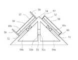
上記課題を解決するため、また、第6発明によれば、温度昇降を繰り返す環境中に配置され、前記環境の温度変化を利用して発電を行う熱電発電装置であって、前記環境が屋外の大気中からなり、前記環境に接触し、前記環境の温度変化に応じて前記環境と熱交換し得る第1および第2の導熱体と、第1および第2の蓄熱体と、前記第1の導熱体および前記第1の蓄熱体間に配置された少なくとも1つの第1の熱流調節ユニットと、前記第2の導熱体および前記第2の蓄熱体間に配置された少なくとも1つの第2の熱流調節ユニットとを備えた熱電発電装置が提供される。
そして、前記第1の熱流調節ユニットは、前記第1の導熱体および前記第1の蓄熱体に接触して前記第1の導熱体と前記第1の蓄熱体の間で熱移動させるON状態と、前記第1の導熱体および前記第1の蓄熱体のうちの少なくとも一方から離間して前記熱移動を停止させるOFF状態とをとる第1の熱流スイッチからなっている。前記第2の熱流調節ユニットは、前記第2の導熱体および前記第2の蓄熱体に接触して前記第2の導熱体と前記第2の蓄熱体の間で熱移動させるON状態と、前記第2の導熱体および前記第2の蓄熱体のうちの少なくとも一方から離間して前記熱移動を停止させるOFF状態とをとる第2の熱流スイッチからなっている。さらに、前記熱電発電装置は、前記第1および第2の蓄熱体間に配置され、一端が前記第1の蓄熱体に接触し、他端が前記第2の蓄熱体に接触する少なくとも1つの熱電変換ユニットを備えている。前記第1および第2の熱流スイッチ、および前記熱電変換ユニットとの接触領域を除く前記第1および第2の蓄熱体の表面が、一定の熱絶縁性を有する被覆層によって覆われている。また、前記第1の導熱体における前記環境との熱交換面に、太陽光スペクトルは透過させるが遠赤外線を透過させないフィルターが、当該熱交換面から間隔をあけて配置されて当該熱交換面の全体を被覆し、前記第2の導熱体における前記環境との熱交換面に、遠赤外線は透過させるが太陽光スペクトルを透過させないフィルターが、当該熱交換面から間隔をあけて配置されて当該熱交換面の全体を被覆している。前記熱電発電装置は、さらに、前記熱電発電装置は、さらに、前記第1の導熱体の温度を検出する第1の温度センサーと、前記第1の蓄熱体の温度を検出する第2の温度センサーと、前記第2の導熱体の温度を検出する第3の温度センサーと、前記第2の蓄熱体の温度を検出する第4の温度センサーと、前記第1〜第4の温度センサーの検出値に基づいて、前記第1および第2の熱流スイッチのON状態とOFF状態を切り替える熱流スイッチ制御部と、を備えている。それによって、前記第1および第2の蓄熱体間に生じる温度差を利用して、前記熱電変換ユニットから電気エネルギーが取り出される。In order to solve the above-mentioned problem, and according to a sixth aspect of the present invention, there is provided a thermoelectric power generation device that is disposed in an environment that repeatedly rises and falls in temperature, and that generates power using the temperature change of the environment, wherein the environment is outdoors. made from the atmosphere,in contact with the environment, and the first and secondheat conductorcapable of the environment and the heat exchanger in accordance with a change in temperature of the environment, and the first and secondregenerator, said first At least one firstheat flow control unit disposed between the heat conductor and the first heat storage body; and at least one secondheat flow disposed between the second heat conductor and the second heat storage body.Athermoelectric generator comprising aconditioning unitis provided .
Then, the first heat flow regulation unit includes a ON state to heat transfer between the first heat-conducting body and the first said contact with the regenerator of the first heat-conducting member and the first regenerator And a first heat flow switch that is in an OFF state in which the heat transfer is stopped by being separated from at least one of the first heat conductor and the first heat storage body. The second heat flow adjustment unit is in an ON state in contact with the second heat conductor and the second heat accumulator to cause heat transfer between the second heat conductor and the second heat accumulator, It consists of the 2nd heat flow switch which takes the OFF state which is spaced apart from at least one of a 2nd heat conducting body and the said 2nd thermal storage body, and stops the said heat transfer. Furthermore, the thermoelectric generator is disposed between the first and second heat storage bodies, and has at least one thermoelectric power source whose one end is in contact with the first heat storage body and whose other end is in contact with the second heat storage body. A conversion unit is provided. The surfaces of the first and second heat storage bodies excluding the contact areas with the first and second heat flow switches and the thermoelectric conversion unit are coveredwith a coating layerhaving a certain thermal insulation property . In addition, a filter that transmits the solar spectrum but does not transmit far-infrared rays is disposed on the heat exchange surface with the environment in the first heat conductor so as to be spaced from the heat exchange surface. A filter that covers the whole and transmits the far-infrared rays but does not transmit the solar spectrum to the heat exchange surface with the environment in the second heat conductor is disposed at a distance from the heat exchange surface. The entire replacement surface is covered. The thermoelectric generator further includes a first temperature sensor that detects a temperature of the first heat conductor, and a second temperature sensor that detects a temperature of the first heat storage body. And a third temperature sensor for detecting the temperature of the second heat conductor, a fourth temperature sensor for detecting the temperature of the second heat storage body, and detection values of the first to fourth temperature sensors. And a heat flow switch control unit that switches between the ON state and the OFF state of the first and second heat flow switches. Thereby, electric energy is taken out from the thermoelectric conversion unit using a temperature difference generated between the first and second heat storage bodies.
本発明によれば、各1つの導熱体および蓄熱体と、導熱体および蓄熱体間に配置された各1つの熱流調節ユニットおよび熱電変換ユニットと、を備え、熱電変換ユニットの一端が導熱体に接触する一方、他端が蓄熱体に接触し、熱電変換ユニットとの接触部を除く蓄熱体の全体が被覆層によって覆われ、被覆層内に熱流調節ユニットとして補助導熱ユニットまたは熱流スイッチが配置される。そして、導熱体の温度が最高温度付近また最低温度付近にあるときに、補助導熱ユニットおよび熱流スイッチを介して導熱体および蓄熱体間に熱移動が生じ、導熱体の温度がそれ以外のときは、補助導熱ユニットおよび熱流スイッチを介した熱移動が生じないように制御がなされる。それによって、導熱体および蓄熱体間に大きな温度差を自動的に生じさせ、この温度差に比例した電圧を熱電変換ユニットから取り出すことができる。According to thepresent invention , each heat conducting body and heat storage body, and each one heat flow adjusting unit and thermoelectric conversion unit disposed between the heat conducting body and the heat storage body, one end of the thermoelectric conversion unit is the heat conducting body. The other end is in contact with the heat storage body, the entire heat storage body excluding the contact portion with the thermoelectric conversion unit is covered with a coating layer, and an auxiliary heat conduction unit or heat flow switchis arranged as a heat flow control unit in the coating layer.The When the temperature of the heat conducting body is near the maximum temperature or near the minimum temperature, heat transfer occurs between the heat conducting body and the heat storage body via the auxiliary heat conducting unit and the heat flow switch, and when the temperature of the heat conducting body is otherwiseControl is performed so that heat transfer does not occur through the auxiliary heat conduction unit and the heat flow switch. Accordingly, a large temperature difference is automatically generated between the heat conductor and the heat storage body, and a voltage proportional to the temperature difference can be taken out from the thermoelectric conversion unit.
本発明によれば、温度差を有する導熱体および蓄熱体間、または蓄熱体間、またはそれらの両方に熱電変換ユニットを配置し、当該温度差に基づき熱電変換ユニットを介して熱エネルギーを熱平衡に向かって移動させ、その熱エネルギーの一部を熱電変換ユニットによって電気エネルギーに変換することで発電を行うが、この場合、蓄熱体には、常に、一定量の熱量が蓄積された状態で、発電に必要な温度差が得られる熱量だけが、蓄熱体に蓄積および放出されるようにすることで、より効率的な発電が実現される(いわゆるエクセルギーの概念)。 According to the present invention, the thermoelectric conversion unit is disposed between the heat conducting body and the heat storage body having a temperature difference, or between the heat storage bodies, or both, and the thermal energy is brought into thermal equilibrium via the thermoelectric conversion unit based on the temperature difference. Power generation is performed by converting a part of the thermal energy into electrical energy by the thermoelectric conversion unit. In this case, the heat storage body always generates power with a certain amount of heat accumulated. More efficient power generation is realized by allowing only the amount of heat that provides the necessary temperature difference to be stored and released in the heat storage body (so-called exergy concept).
こうして、本発明によれば、温度昇降を繰り返す環境中に熱電発電装置を配置するだけで電気エネルギーを取り出すことができ、従来の熱電発電装置のように、熱電発電装置が配置された環境中の熱電変換ユニットを挟んだ両側に温度差を生じさせるべく、熱電変換ユニットの一端側を加熱し、他端側を冷却する必要がない。 Thus, according to the present invention, electric energy can be taken out simply by arranging the thermoelectric generator in an environment where the temperature rise and fall is repeated, and in the environment where the thermoelectric generator is arranged like the conventional thermoelectric generator. There is no need to heat one end side of the thermoelectric conversion unit and cool the other end side so as to cause a temperature difference between both sides of the thermoelectric conversion unit.
以下、添付図面を参照して本発明の好ましい実施例を説明する。
本発明による熱電発電装置は、温度昇降を繰り返す環境中に配置されるようになっている。ここに、「温度昇降を繰り返す環境」には、昼夜で周期的に温度変化する屋外の大気中や、屋内に配置され、稼働状態に応じて温度変化する機械設備の近傍および表面上等が含まれる。Hereinafter, preferred embodiments of the present invention will be described with reference to the accompanying drawings.
The thermoelectric generator according to the present invention is arranged in an environment where temperature rise and fall is repeated. Here, the “environment in which temperature rises and falls repeatedly” includes the outdoors and the surface of mechanical equipment that is placed indoors and changes temperature according to the operating state, etc. It is.
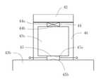
図1は、本発明の1実施例による熱電発電装置の構成を示す縦断面図である。
図1に示された実施例では、本発明による熱電発電装置は、環境に接触し、環境の温度変化に応じて環境と熱交換し得る1つの導熱体1と、1つの蓄熱体2と、導熱体1および蓄熱体2間に配置された少なくとも一対(この実施例では一対)の熱電変換ユニット3および熱流調節ユニット6を備えている。熱流調節ユニット6は、この実施例では、熱抵抗体からなっている。FIG. 1 is a longitudinal sectional view showing the configuration of a thermoelectric generator according to one embodiment of the present invention.
In the embodiment shown in FIG. 1, the thermoelectric generator according to the present invention is in contact with the environment and can exchange heat with the environment according to the temperature change of the environment, one
そして、熱抵抗体6の一端6aと熱電変換ユニット3の一端3aが接触し、熱抵抗体6の他端6bが導熱体1に接触し、熱電変換ユニット3の他端3bが蓄熱体2に接触している。なお、熱電変換ユニット3と熱抵抗体6との位置関係は、この実施例に限定されず、熱電変換ユニッ3と熱抵抗体6が上下に逆転して配置されていてもよい。
また、熱抵抗体6は、この実施例では、熱電変換ユニット3とは別個の構成要素となっているが、熱抵抗体6が熱電変換ユニット3に組み込まれていてもよいし、熱電変換ユニット3自体が、熱抵抗体6の熱抵抗値に相当する熱抵抗値を有していてもよい(この場合には、熱抵抗体6は不要)。Then, one
Further, in this embodiment, the
また、熱電変換ユニット3との接触領域を除く蓄熱体2の表面が、一定の熱絶縁性を有する被覆層4によって覆われている。
ここで、被覆層4は一定の熱絶縁性、すなわち一定の熱抵抗を有するが、被覆層4の熱抵抗は、導熱体1、熱電変換ユニット3、熱抵抗体6および蓄熱体2から形成される熱経路全体の熱抵抗と比較して十分に(1桁程度)大きければよい。
被覆層4は、一定の熱絶縁性を有し、熱電変換ユニット3との接触領域を除く蓄熱体2の表面を被覆するものであればよく、その形成材料や構造に特に制限はない。この実施例では、被覆層4は、熱電変換ユニット3との接触領域を除く蓄熱体2の表面を被覆する公知の適当な断熱材からなっている。Further, the surface of the
Here, the
The
被覆層4に覆われた蓄熱体2は、好ましくは、角がなく全体に丸味を帯び、表面積が出来るだけ小さくなるような形状とされる。
熱電変換ユニット3としては、熱エネルギーを電気エネルギーに変換し得る任意のものが使用可能であるが、この実施例では、ゼーベック効果を利用した熱電変換モジュールが使用される。なお、図1中、5は、熱電変換モジュールの一対の電極である。The
As the
導熱体1は、環境との熱交換(熱吸収および放熱)がより高い効率で行えるような構成を有していることが好ましい。そのため、例えば、熱電発電装置の設置環境が、温度変化する大気中である場合は、できるだけ大きな導熱体1の表面積を確保すべく、導熱体1の表面が凹凸を有し、または粗面に形成されていることが好ましく(伝導、対流の促進)、また、導熱体1の表面が黒色等の濃い色を有していることが好ましい(放射の促進)。また、例えば、熱電発電装置の設置環境が、稼働状態によって温度変化する機械設備の表面である場合は、導熱体1が機械設備の表面に密着すべく、当該表面に適合する形状を有していることが好ましい(伝導の促進)。 It is preferable that the
環境が屋外の大気中である場合には、導熱体1または熱電発電装置本体を動かすことができるような構成とし、導熱体1における環境との熱交換面が太陽に向くように調節可能にすれば、季節を通じたまたは1日を通じた日照角度の変化が生じても、日射を効率良く受けることができるので、より好ましい。
別の好ましい実施例によれば、反射板または集光器(集光レンズ)が導熱体1の前面に配置され、それらを通じて導熱体1が環境から熱を受けるようになっている。それによって、導熱体1の受ける熱量がより増加する。When the environment is in the outdoor atmosphere, the
According to another preferred embodiment, a reflector or a condenser (condenser lens) is arranged in front of the
蓄熱体2は、水等の液体によって満たされた、防水性を有する容器からなっていてもよく、この場合、容器の壁の少なくとも熱電変換ユニットとの接触領域は、熱伝導性を有している。
容器を満たす液体は、腐敗しにくく、凍結しにくいものであれば、どのような液体からなっていてもよく、例えば、純水、または純水に不凍液を混合したもの、または純水に防腐剤を混合したものを使用することができる。なお、液体にはゲル状のものも含まれる。The
The liquid filling the container may be any liquid as long as it is hard to rot and freeze, for example, pure water, pure water mixed with antifreeze, or pure water with a preservative. A mixture of these can be used. The liquid includes a gel.
蓄熱体2は、固体状の金属または非金属からなっていてもよく、この場合、蓄熱体2として、アルミニウム塊またはプラスチック塊またはコンクリート塊を用いることが好ましい。
蓄熱体2は、また、潜熱蓄熱材からなっていてもよく、この場合、潜熱蓄熱材の相変化(相転移)物質は、特に限定されない。潜熱蓄熱材は、酢酸ナトリウム水和物、硫酸ナトリウム水和物または石油精製品のパラフィン等の、相変化温度での融解熱または凝固熱を利用するもので、上述の比熱が一定の液体や固体からなる蓄熱体と比べて、より大きな熱容量の蓄熱体とすることができる。The
The
この場合、蓄熱体は、異なる相変化温度を有する複数の蓄熱材から構成されていることがより好ましい。かかる構成の1例を図5に示した。
図5Aを参照して、この実施例では、蓄熱体2’は、導熱性を有するケーシング47と、ケーシング47内に収容され、蓄熱体2の動作温度範囲内の異なる温度で機能する3つの潜熱蓄熱材48a〜48cとからなっている。この実施例では、潜熱蓄熱材48a〜48cは液体状またはゲル状であり、それぞれ専用の容器内に充填されている。そして、ケーシング47の内部が、導熱性を有する仕切壁によって3つの部屋に仕切られ、部屋毎に異なる潜熱蓄熱材48a〜48cが収容されている。なお、仕切壁は、潜熱蓄熱材48a〜48cの全体が均一に熱交換し得るようにするためのものであり、必要に応じて設けられる。また、潜熱蓄熱材48a〜48cが粒状である場合は、潜熱蓄熱材48a〜48cの混合物がケーシング47内に収容される。In this case, it is more preferable that the heat storage body is composed of a plurality of heat storage materials having different phase change temperatures. An example of such a configuration is shown in FIG.
Referring to FIG. 5A, in this embodiment,
図5Bは、図5Aに示した蓄熱体2’と、比熱が一定の液体または固体からなる通常の蓄熱体の、温度変化に伴う蓄熱量(または放熱量)の変化を比較したグラフである。グラフ中、直線αは通常の蓄熱体を表し、折れ線βは蓄熱体2’を表し、T0〜T1は、蓄熱体の動作温度範囲を表し、T2、T3、T4はそれぞれ第1の潜熱蓄熱材48a、第2の潜熱蓄熱材48bおよび第3の潜熱蓄熱材48cが機能する温度を表している。なお、折れ線βにおいては、各潜熱蓄熱材の熱抵抗および熱容量による影響は考慮されていない。FIG. 5B is a graph comparing changes in the amount of stored heat (or the amount of heat released) accompanying a temperature change between the
今、例えば、蓄熱体がT0=5℃からT1=25℃の範囲内(温度差20℃)で動作し、各潜熱蓄熱材48a〜48cの重さが200gであり、融解熱が200kJ/kgであり、顕熱の比熱が2kJ/(kg・K)であるとし、ケーシング47の比熱等は無視すると、蓄熱体2’に関し、
潜熱の熱量=200(kJ/kg)×0.6(kg)=120(kJ)
顕熱の熱量=2(kJ/(kg・K))×0.6(kg)×20(K)=24(kJ)
潜熱と顕熱の合計熱量=120(kJ)+24(kJ)=144(kJ)
となる。
一方、水(自然界では最大の比熱を有する)0.6kgからなる通常の蓄熱体で20℃の温度変化をさせると、
熱量(顕熱のみ)=4.2(kJ/(kg・K))×0.6(kg)×20(K)
=50.4(kJ)
となる。そして、
144(kJ)/50.4(kJ)=2.86
であり、水の2.86倍の比熱をもつ蓄熱体2’が得られたことになる。それによって、よりコンパクトでかつ発電量の大きい熱電発電装置が実現される。Now, for example, the heat storage body operates within a range of T0 = 5 ° C. to T1 = 25 ° C. (
Heat quantity of latent heat = 200 (kJ / kg) × 0.6 (kg) = 120 (kJ)
Amount of sensible heat = 2 (kJ / (kg · K)) × 0.6 (kg) × 20 (K) = 24 (kJ)
Total heat of latent heat and sensible heat = 120 (kJ) +24 (kJ) = 144 (kJ)
It becomes.
On the other hand, when a normal heat storage body composed of 0.6 kg of water (having the largest specific heat in nature) is used, a temperature change of 20 ° C. is performed.
Amount of heat (sensible heat only) = 4.2 (kJ / (kg · K)) × 0.6 (kg) × 20 (K)
= 50.4 (kJ)
It becomes. And
144 (kJ) /50.4 (kJ) = 2.86
Thus, a
熱抵抗体6は、蓄熱体2の熱容量と、熱電変換ユニット3の発電効率(熱電変換ユニット3による発電に伴う熱移動)を考慮しつつ、蓄熱体2の温度を導熱体1の最高温度と最低温度の中間の温度付近に保つことができる程度の熱抵抗を有しておればよい。
装置設計上、熱抵抗体6の熱抵抗値は、外部環境と導熱体1間の熱抵抗、および導熱体1と熱抵抗体6間の熱抵抗、および熱電変換ユニット3の熱抵抗、および熱抵抗体6と熱電変換ユニット3間の熱抵抗、および熱電変換ユニット3と蓄熱体2間の熱抵抗の総和に、蓄熱体2の熱容量を乗算した値として定まる熱時定数が、熱電発電装置が配置される環境の温度昇降の繰り返し周期(よって、導熱体1の温度昇降の繰り返し周期)と蓄熱体2の温度昇降の繰り返し周期との間に一定程度の遅延を生じさせ、それによって、導熱体1および蓄熱体2間に発電に必要な温度差を生じさせる適当な熱時定数となるように、設定される。
熱抵抗体6としては、例えば、金属製の棒体および板体や、金属ファイバーの集合体や、化学繊維集合体等が使用可能である。The
In the device design, the thermal resistance value of the
As the
また、装置設計上、あるいは構造上、例えば、蓄熱体2の全体が被覆層4によって完全に覆われず、蓄熱体2の一部が外部の環境に接していても、前記の「一定の熱絶縁性」が確保され、上記の熱抵抗の総和と蓄熱体2の熱容量を乗算した値により適当な熱時定数が実現されておればよい。 Further, in terms of device design or structure, for example, even if the entire
次に、本発明による熱電発電装置の動作を説明する。
今、熱電発電装置を屋外の大気中に配置した場合を考える。日本各地の一日の最高気温と最低気温の温度差は、平均すると約10℃であることが知られているので、本発明の熱電発電装置を配置した環境においても、一日の気温差が約10℃であるとする。Next, the operation of the thermoelectric generator according to the present invention will be described.
Consider a case where a thermoelectric generator is placed in the outdoor atmosphere. It is known that the average temperature difference between the highest and lowest temperatures in Japan is about 10 ° C on average, so even in the environment where the thermoelectric generator of the present invention is placed, Suppose that it is about 10 degreeC.
なお、この実施例では、北緯30〜45°に位置し海洋に囲まれた日本での気温を前提とするが、地球上のどの地域においても、昼間は太陽の日射による加熱が生じる一方、夜間は放射冷却による冷却が生じ、昼夜の繰り返しが気温変化を生じさせることに変わりはなく、よって、本発明による熱電発電装置は、地域によらず動作することは言うまでもない。 In this embodiment, it is assumed that the temperature in Japan is 30-45 ° north latitude and surrounded by the ocean. However, in any region on the earth, heating occurs due to solar radiation in the daytime. Cooling by radiant cooling occurs, and the repetition of day and night causes a change in air temperature. Therefore, it goes without saying that the thermoelectric generator according to the present invention operates regardless of the area.
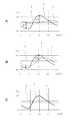
図2は、このような環境中における、本発明の熱電発電装置の導熱体1と蓄熱体2の一日の温度変化を例示したグラフである。図2のグラフ中、縦軸は温度(℃)を、横軸は時刻(時)を表し、曲線Xおよび曲線Yはそれぞれ導熱体1の温度変化および蓄熱体2の温度変化を示し、また直線Zは蓄熱体2の平均温度を示している。
図2A〜Cのグラフの曲線Xに示すように、熱電発電装置の導熱体1の温度は、気温変化にほぼ追従して、約10℃の温度範囲内で昇降する。FIG. 2 is a graph exemplifying a daily temperature change of the
2A to 2C, the temperature of the
また、導熱体1と蓄熱体2との間には熱移動が生じ、それによって蓄熱体2の温度も変化するが、この場合、導熱体1、熱抵抗体6、熱電変換ユニット3および蓄熱体2から形成される熱回路全体の熱抵抗に、蓄熱体2の熱容量を乗算した値として定まる熱時定数に応じて、導熱体1の温度変化よりも遅延する(温度変化の位相がずれる)。 In addition, heat transfer occurs between the
さらには、被覆層4の熱抵抗は有限であるから、被覆層4から熱漏洩が生じ、かつ熱電変換ユニット3の発電に伴う熱移動が生じる。
その結果、蓄熱体2の温度は、導熱体1の最高温度と最低温度の中間温度付近で変化し、導熱体1と蓄熱体2の温度差は、導熱体1の最高温度と最低温度の差(約10℃)の半分の約5℃を最大値として、0℃〜約5℃の範囲内で変動する。Furthermore, since the thermal resistance of the
As a result, the temperature of the
図2Bは、発電に必要な導熱体1および蓄熱体2の温度差が得られるように、導熱体1、熱抵抗体6、熱電変換ユニット3および蓄熱体2から形成される熱回路全体の熱抵抗と、蓄熱体2の熱容量が設定された場合のグラフである。
そして、このグラフにおいては、熱時定数は、一日の気温変化(よって、導熱体1の温度変化)のグラフが24時間の周期をもつ正弦波であるとした場合に、蓄熱体2の温度変化の位相が45度(3時間)ずれるように設定されている。
この場合、熱時定数は、次のように決定される。すなわち、
R=導熱体1、熱抵抗体6、熱電変換ユニット3および蓄熱体2からなる熱回路全体の熱抵抗
C=蓄熱体の熱容量
ω=2πf=角周波数(f:周波数)
として、45度の位相差が生じているので、熱抵抗Rと蓄熱体2の正弦波交流(変化)に対する熱抵抗(インピーダンス)1/ωCの絶対値は等しい。よって、
R=1/ωC
であるから、
熱時定数t=RC=1/2πf=24/2π=3.82(時間)
[周期=24時間であるから、f=1/24]FIG. 2B shows the heat of the entire thermal circuit formed from the
In this graph, the thermal time constant is the temperature of the
In this case, the thermal time constant is determined as follows. That is,
R = thermal resistance of the entire thermal circuit composed of the
As a phase difference of 45 degrees is generated, the absolute values of the thermal resistance R and the thermal resistance (impedance) 1 / ωC with respect to the sinusoidal alternating current (change) of the
R = 1 / ωC
Because
Thermal time constant t = RC = 1 / 2πf = 24 / 2π = 3.82 (hours)
[Frequency = 24 hours, so f = 1/24]
このグラフにおいては、発電による熱移動量の増大に伴って蓄熱体2の温度変化量が導熱体1の温度変化量の1/2(約5℃)を超えても、蓄熱体2の温度変化と導熱体1の温度変化の位相差があるために、蓄熱体2と導熱体1との温度差ΔTは、1/2までも低下せず、80%程度に維持されている。
こうして、1日の気温の変化を通じて、実際に発電に使用可能な、導熱体1と蓄熱体2の温度差約5℃が確保され得る。そして、この温度差ΔTに応じて、導熱体1の昇温時と降温時の2回にわたって発電が行われ、その積分値が一周期(昼夜1サイクル)の発電電力量となる。In this graph, the temperature change of the
Thus, a temperature difference of about 5 ° C. between the
一方、図2Cのグラフに示すように、蓄熱体2がより小さい熱容量を有するように設計され、あるいは、導熱体1および蓄熱体2間の熱抵抗が小さくなるように設計された場合、曲線Yは次第に曲線Xに近づき、その結果、導熱体1と蓄熱体2の温度差は小さくなり、有効な発電はできなくなる。
また、図2Aのグラフに示すように、蓄熱体2がより大きい熱容量を有するように設計され、あるいは、導熱体1および蓄熱体2間の熱抵抗が大きくなるように設計された場合、曲線Yは、曲線Xの最大値と最小値の中間値付近において次第にフラットになり平均温度を示す直線Zに近づく。その結果、導熱体1と蓄熱体2の温度差が大きくなる。これは発電条件としては問題ないが、現実的な設計であるとは言えない。On the other hand, as shown in the graph of FIG. 2C, when the
In addition, as shown in the graph of FIG. 2A, when the
こうして、本発明によれば、一日を通じて有効な発電が実現できるようにするため、熱時定数は、一日の温度変化のグラフが周期24時間の正弦波に一致するとした場合に、当該周期の1/10の2.4時間以上となるように予め設定されている。 Thus, according to the present invention, in order to realize effective power generation throughout the day, the thermal time constant is determined when the graph of the temperature change of the day coincides with a sine wave with a period of 24 hours. Is set in advance to be 1/10 of 2.4 hours or longer.
次に、図2Bのグラフの場合に、実際にどれくらいの電力量が得られるかを見積もることにする。
例えば、蓄熱体2を1000mLの水で満たされた容器から構成した場合には、容器の熱容量を小さいとして無視すると、上記考察に基づき、蓄熱体2の温度変化を2℃として、蓄熱体2の熱容量は、水の比熱が1cal/gであり、1cal=4.2Jであるから、次のようになる。
熱容量=1×1000×2=2000(cal)
=8400(J)=8400(Ws)=2.33(Wh)
熱量2000calを電気エネルギーの単位であるジュール(1J=1Ws)に変換すると、2.33Whであるが、熱エネルギーを熱電変換ユニット3で電気エネルギーに変換する場合、変換効率には限界がある。
仮に、熱電変換ユニット3の発電効率が5%であるとすると、発電で得られる電力量は116.7mWhとなり、昼夜2回の同量の発電が可能であれば、1日当たり233mWhの電力量を得ることができる。
こうして、一定の熱量の熱エネルギーが、一定の発電効率を有する熱電発電装置の働きによって一定の電力量の電気エネルギーに変換される。Next, in the case of the graph of FIG. 2B, it is estimated how much power can actually be obtained.
For example, when the
Heat capacity = 1 × 1000 × 2 = 2000 (cal)
= 8400 (J) = 8400 (Ws) = 2.33 (Wh)
When the amount of heat of 2000 cal is converted to joule (1J = 1 Ws) which is a unit of electric energy, it is 2.33 Wh. However, when the heat energy is converted into electric energy by the
Assuming that the power generation efficiency of the
Thus, the heat energy having a constant heat amount is converted into electric energy having a constant power amount by the action of the thermoelectric power generator having a constant power generation efficiency.
1000mLの水は、一辺が10cmの立方体の容器内に充填可能であるが、使用する水の量を1/10の100mLとして、2.5cm×4cm×10cmの直方体容器内に充填した蓄熱体2の場合、前と同じ発電効率であれば、1日当たり23.3mWhの電力量が得られる。 1000 mL of water can be filled in a cubic container having a side of 10 cm, but the amount of water used is 1/10 of 100 mL, and the
この電力量は、通常の小電力型の電子機器(消費電力が数μW程度)を作動させるのに十分な大きさである。例えば、50μWの電子機器を1日(24時間)動作させるのに必要な電力量は、50×24=1,200μWh=1.2mWhであり、仮に熱電発電装置の発電効率が5%のさらに数分の1であっても十分に供給可能な量である。 This amount of power is large enough to operate a normal low-power electronic device (power consumption is about several μW). For example, the amount of power required to operate a 50 μW electronic device for one day (24 hours) is 50 × 24 = 1,200 μWh = 1.2 mWh, and the power generation efficiency of the thermoelectric generator is 5%. Even if it is a fraction, it is an amount that can be sufficiently supplied.
また、蓄熱体2を体積100mLのアルミニウムから構成した場合には、蓄熱体2の温度変化を2℃として、蓄熱体2の熱容量は、アルミニウムの比熱が0.21cal/gで、比重が2.7であるから、次のようになる。
熱容量=0.21×2.7×100×2=113.4(cal)
=476(J)=476(Ws)=0.132(Wh)
そして、熱電変換ユニット3の発電効率が5%であるとすると、発電で得られる電力量は6.6mWhとなり、昼夜2回の同量の発電が可能であれば、1日当たり13.2mWhの電力量(水の場合の約0.57倍の電力量)を得ることができる。
この場合、アルミニウムは、水よりも高価であるが、加工等の取扱いが容易であり、水を使用した場合と比較して蓄熱体2の構造を簡略化することができる。Further, when the
Heat capacity = 0.21 x 2.7 x 100 x 2 = 113.4 (cal)
= 476 (J) = 476 (Ws) = 0.132 (Wh)
If the power generation efficiency of the
In this case, although aluminum is more expensive than water, it is easy to handle such as processing, and the structure of the
こうして、本発明の熱電発電装置においては、温度昇降を繰り返す環境に熱的に接触する導熱体1と、被覆層4の作用によって該環境から熱的影響を受けにくい蓄熱体2と、一端が熱抵抗体6を介して導熱体1に熱的に接触し、他端が蓄熱体2に熱的に接触する熱電変換ユニット3とを備え、導熱体1の温度を環境の温度変化に従って昇降させる一方、蓄熱体2の温度を導熱体1の最高温度と最低温度の中間付近の温度に保つようにし、導熱体1および蓄熱体2間に自動的に生じた温度差に比例した電圧を熱電変換ユニット3から取り出すことができる。 Thus, in the thermoelectric generator of the present invention, the
すなわち、本発明によれば、熱電発電装置を温度昇降を繰り返す環境中に配置するだけで電気エネルギーを取り出すことができ、従来の熱電発電装置のように、熱電発電装置が配置された環境中の熱電変換ユニットを挟んだ両側に温度差を生じさせるべく、熱電変換ユニットの一端側を加熱し、他端側を冷却する必要がない。
そして、本発明による熱電発電装置をワイヤレスセンサーやリモートモニター等の電子機器の電源として使用した場合には、商用電源から電子機器への電力供給配線や電池の交換作業が不要な独立電源が得られ、これらの電子機器を必要な場所に自由に設置することができる。That is, according to the present invention, it is possible to take out electrical energy simply by placing the thermoelectric generator in an environment where the temperature rises and falls repeatedly, and in the environment where the thermoelectric generator is placed like the conventional thermoelectric generator. There is no need to heat one end side of the thermoelectric conversion unit and cool the other end side so as to cause a temperature difference between both sides of the thermoelectric conversion unit.
When the thermoelectric generator according to the present invention is used as a power source for an electronic device such as a wireless sensor or a remote monitor, an independent power source that does not require power supply wiring or battery replacement work from the commercial power source to the electronic device can be obtained. These electronic devices can be freely installed where necessary.
また、本発明の熱電発電装置を、導熱体1が直射日光や散乱光を受け得る場所に設置するとともに、導熱体1を、日射を受けやすく、しかも夜間には放射冷却されやすいような構造とすることによって、導熱体1の最高温度および最低温度の差をより大きくすれば、発電電力をさらに増大させることができる。 In addition, the thermoelectric generator of the present invention is installed in a place where the
この場合には、導熱体1の表面に凹凸が形成されないようにして、空気との接触面積をできるだけ小さくすることが好ましい。それによって、導熱体1が日射によって空気温度より高温になったときに、空気によって冷却されること、および、導熱体1が放射冷却によって低温になったときに、空気によって暖められることが防止される。
なお、この場合、空気の影響を遮断すべく、ガラス等の透明板を使用し、導熱体1と透明板との間を真空にして断熱してもよい。透明板は、太陽光線や赤外線の透過、反射および吸収の特性を適切に考慮し、適切な材質のものを用いることが好ましい。In this case, it is preferable to make the contact area with the air as small as possible so that the surface of the
In this case, in order to block the influence of air, a transparent plate such as glass may be used, and the
図3には、本発明の別の実施例による熱電発電装置を示した。なお、図3中、図1に示したものと同じ構成要素には同一番号を付し、以下ではそれらの詳細な説明を省略する。
図3Aを参照して、この実施例では、導熱体1’が被覆層4の表面の全体を覆っている。この構成によれば、熱電発電装置全体の体積はさほど増大させずに、導熱体1’の表面積をかなり増大させることができ、それによって、導熱体1’の環境との熱交換の効率をより高めることができる。さらには、導熱体1’を金属等の硬質の材料から形成した場合には、蓄熱体2、熱抵抗体6、熱電変換ユニット3および被覆層4を導熱体1’によって保護することができる。FIG. 3 shows a thermoelectric generator according to another embodiment of the present invention. In FIG. 3, the same components as those shown in FIG. 1 are denoted by the same reference numerals, and detailed description thereof will be omitted below.
With reference to FIG. 3A, in this embodiment, the
また、図3Bを参照して、この実施例では、蓄熱体2が、液体7aで満たされた容器7bから構成されている。この場合、容器7bの内壁面に、複数の熱交換用フィン8を互いに間隔をあけて設ける等の、液体7aの熱伝導や対流を促進する手段を容器7b内に設けることがより好ましい。 Moreover, with reference to FIG. 3B, in this Example, the
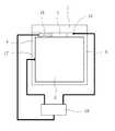
図4は、本発明による熱電発電装置を低消費電力の電子機器の電源部に組み込んだ場合の構成の1例を示した図である。なお、図4中、図1に示したものと同じ構成要素には同一番号を付し、以下では、それらの詳細な説明を省略する。
図4を参照して、本発明の熱電発電装置においては、設置環境の温度昇降によって一対の電極5に交流が発生するので、電源部10は、本発明の熱電変換装置のほかに、熱電発電装置の熱電変換ユニット3の一対の電極5に接続された極性・電圧変換回路11と、極性・電圧変換回路11の後段に接続されたリチウムイオン電池等の二次電池12とを備えている。FIG. 4 is a diagram showing an example of a configuration when the thermoelectric generator according to the present invention is incorporated in a power supply unit of a low power consumption electronic device. In FIG. 4, the same components as those shown in FIG. 1 are denoted by the same reference numerals, and detailed description thereof will be omitted below.
Referring to FIG. 4, in the thermoelectric power generation device of the present invention, an alternating current is generated in the pair of
こうして、本発明の熱電発電装置による発電電力を一旦二次電池12に蓄え、二次電池12から電子機器13に供給することによって、電子機器13の動作のために必要とされるときに、安定して電力を供給することができる。
この実施例では、本発明の熱電発電装置は電子機器13に内蔵され、あるいは電子機器13とは独立に設けられるが、電子機器の一部(例えば筐体)が、熱電発電装置の導熱体の全体あるいは一部を構成するようにしてもよい。
また、電子機器13を、本発明の熱電発電装置の蓄熱体内に配置することもできる。この構成によれば、電子機器13の温度を、外部環境の最高温度と最低温度の中間温度付近に保つことができ、それによって、電子機器13を温度ストレスから保護し、安定的に動作させることができる。Thus, the power generated by the thermoelectric generator of the present invention is temporarily stored in the
In this embodiment, the thermoelectric power generation device of the present invention is built in the
Moreover, the
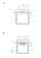
図6は、本発明のさらに別の好ましい実施例による熱電発電装置の主要部を示す拡大縦断面図である。図6の実施例は、熱流調節ユニットとして熱抵抗体6を熱電変換ユニット3に直列に配置する代わりに、補助導熱ユニットを被覆層4の内部に組み込んだ点が、図1の実施例と異なるだけである。よって、図6中、図1に示したものと同じ構成要素には同一番号を付し、以下では、それらの詳細な説明を省略する。 FIG. 6 is an enlarged longitudinal sectional view showing a main part of a thermoelectric generator according to still another preferred embodiment of the present invention. The embodiment of FIG. 6 differs from the embodiment of FIG. 1 in that an auxiliary heat conducting unit is incorporated in the
図6を参照して、この実施例では、熱流調節ユニットとして補助導熱ユニット14が被覆層4内における導熱体1および蓄熱体2間に組み込まれている。なお、この実施例では、単一の補助導熱ユニット14が組み込まれているが、必要に応じて、複数の補助導熱ユニット14が組み込まれ得る。
補助導熱ユニット14は、被覆層4を貫通して導熱体1および蓄熱体2間にのびる開口9内に取付けられ、熱的に膨張および収縮すること、または熱的に変形することで、導熱体1および蓄熱体2に接触して導熱体1と蓄熱体2の間で熱移動させる第1の位置と、導熱体1および蓄熱体2のうちの少なくとも一方から離間して熱移動を停止させる第2の位置をとる。
そして、補助導熱ユニット14は、導熱体1の温度が最高温度付近にあるときまたは導熱体1の温度が最低温度付近にあるときは第1の位置をとる一方、それ以外のときは第2の位置をとるように動作する。With reference to FIG. 6, in this embodiment, an auxiliary
The auxiliary
The auxiliary
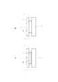
図7および図8は、図6における補助導熱ユニットの取付部の拡大図であり、補助導熱ユニット14を例示したものである。
図7に示した実施例では、補助導熱ユニット14は、バイメタル14aからなっている。バイメタル14aは、アーチ状に形成され、導熱体1側が凸になる配置で、下端部が蓄熱体2に接触状態で固定されている。そして、バイメタル9aは、導熱体1が最高温度付近にあるとき(導熱体1の高温時)または導熱体1が最低温度付近にあるとき(導熱体1の低温時)に大きく変形して、アーチの頂点領域を導熱体1に接触させ、第1の位置をとる(図7B参照)が、それ以外の期間は、導熱体1に接触しない範囲内で変形し、第2の位置をとる(図7A参照)。7 and 8 are enlarged views of the attachment portion of the auxiliary heat conducting unit in FIG. 6, and illustrate the auxiliary
In the embodiment shown in FIG. 7, the auxiliary
図8に示した実施例では、補助導熱ユニット14は、熱収縮材料14bからなっている。熱収縮材料14bとしては、例えば、熱収縮ゴムに熱伝導性を高める金属粉を配合したものが使用できる。熱収縮材料14bは、上面が導熱体1に接触状態で固定されている。そして、熱収縮材料14bは、導熱体1が最高温度付近にあるとき(導熱体1の高温時)に大きく膨張して、下面を蓄熱体2に接触させ、第1の位置をとる(図8B参照)が、それ以外のときは、蓄熱体2に接触しない範囲で膨張・収縮し、第2の位置をとる(図8A参照)。 In the embodiment shown in FIG. 8, the auxiliary
図9は、図6に示した熱電発電装置を屋外の大気中に配置した場合の、導熱体1と蓄熱体2の温度変化の一例を示す図2に類似のグラフであり、グラフ中、曲線Xは導熱体1の温度変化を示し、曲線Yは蓄熱体2の温度変化を示している。また、図9のグラフ中、Shは、補助導熱ユニット14が第1の位置をとっている期間を示している。 FIG. 9 is a graph similar to FIG. 2 showing an example of the temperature change of the
図9のグラフからわかるように、図6の実施例によれば、導熱体1の高温時には、蓄熱体2の温度が導熱体1の温度付近まで上昇し、それによって、導熱体1および蓄熱体2間の、導熱体1の最高温度と最低温度の差に近い温度差ΔTが得られる。その結果、補助導熱ユニット14を備えていない場合と比べて約2倍の温度差となり、この温度差に比例して、熱電変換ユニット3の出力電圧が約2倍になる。 As can be seen from the graph of FIG. 9, according to the embodiment of FIG. 6, when the
この場合、負荷抵抗が一定であれば、得られる電力は電圧の2乗に比例するので、電圧が2倍であれば、熱電発電装置によって得られる電力量は4倍となり、蓄熱体の熱容量が同じであっても、より多くの電力量が得られることになる。 In this case, if the load resistance is constant, the electric power obtained is proportional to the square of the voltage, so if the voltage is double, the amount of electric power obtained by the thermoelectric generator is quadrupled, and the heat capacity of the heat accumulator is increased. Even if they are the same, more electric energy can be obtained.
図6に示した実施例では、熱流調節ユニットとして、導熱体1の温度変化(外部環境の温度変化)に応じて、膨張・収縮または変形することによって受動的に熱移動を制御する補助導熱ユニットを配置したが、その代わりに、能動的に熱移動を制御する熱流スイッチを配置することもできる。 In the embodiment shown in FIG. 6, as the heat flow adjusting unit, an auxiliary heat conducting unit that passively controls heat transfer by expanding, contracting, or deforming according to a temperature change (temperature change in the external environment) of the
図10には、熱流調節ユニットとして熱流スイッチを備えた熱電発電装置の構成を示した。なお、図10中、図6に示したものと同じ構成要素には同一番号を付し、以下では、それらの詳細な説明を省略する。
図10に示した実施例では、被覆層4内における導熱体1および蓄熱体2間に、熱流調節ユニットとして、導熱体1および蓄熱体2に接触して導熱体1と蓄熱体2の間で熱移動させるON状態と、導熱体1および蓄熱体2のうちの少なくとも一方から離間して前記熱移動を停止させるOFF状態とをとる熱流スイッチ15が配置される。なお、この実施例では、単一の熱流スイッチ15が配置されるが、必要に応じて、複数の熱流スイッチ15が配置され得る。FIG. 10 shows a configuration of a thermoelectric generator having a heat flow switch as a heat flow adjusting unit. In FIG. 10, the same components as those shown in FIG. 6 are denoted by the same reference numerals, and detailed description thereof will be omitted below.
In the embodiment shown in FIG. 10, between the
また、導熱体1の温度を検出する第1の温度センサー16と、蓄熱体2の温度を検出する第2の温度センサー17が備えられる。第1および第2の温度センサー16、17は、熱流スイッチ15からできるだけ離れた位置であって、それぞれ、導熱体1および蓄熱体2の中心または平均温度を示す位置に配置されることが好ましい。
さらに、熱流スイッチ制御部18が備えられ、第1および第2の温度センサー16、17の検出値に基づいて、熱流スイッチ15のON状態とOFF状態を切り替えるようになっている。Further, a
Further, a heat flow
熱流スイッチ15の機能は、基本的に補助導熱ユニットと同様である。
例えば、蓄熱体2の温度を導熱体1の高温側にシフトさせる場合は、熱流スイッチ制御部18が、第1および第2の温度センサー16、17の検出値に基づき、導熱体1の温度が蓄熱体2の温度よりも高く、かつその温度差が予め設定された値以上であると判定したとき、熱流スイッチ15をON状態にする一方、導熱体1の温度が蓄熱体2の温度よりも高いが、その温度差が予め設定された値以下であると判定したとき、または、導熱体1の温度が蓄熱体2の温度よりも低いと判定したときは、熱流スイッチ15をOFF状態とする。
なお、熱流スイッチ15の作動は、熱電発電装置が出力する電力の一部を用いてなされる。The function of the
For example, when the temperature of the
The operation of the
もちろん、熱流スイッチ15によって、蓄熱体2の温度を導熱体1の低温側にシフトさせることもでき、この場合には、熱流スイッチ制御部18が、第1および第2の温度センサー16、17の検出値に基づき、導熱体1の温度が蓄熱体の温度よりも低く、かつその温度差が予め設定された温度以上であると判定したときにのみ、熱流スイッチ15をON状態にする。 Of course, the
図11および図12は、図10における熱流スイッチの取付部の拡大図であり、熱流スイッチを例示したものである。
図11に示した実施例では、熱流スイッチ15は、リニアアクチュエータ29aと、リニアアクチュエータ29aの操作ロッドの先端に接続された可動導熱ブロック29bとから構成される。そして、熱流スイッチ15がOFF状態にあるときは、図11Aに示すように、リニアアクチュエータ29aの操作ロッドは引っ込んだ位置にあって、可動導熱ブロック29bは導熱体1および蓄熱体2から離間しているが、例えば、熱流スイッチ制御部18によって、導熱体1の温度が蓄熱体2の温度よりも高くかつその温度差が予め設定された値以上であると判定されたとき、熱流スイッチ15はON状態になり、図11Bに示すように、リニアアクチュエータ29aの操作ロッドが突き出し、可動導熱ブロック29bが導熱体1および蓄熱体2に接触し、それによって、導熱体1から蓄熱体2に熱が移動し、蓄熱体2が加熱され、蓄熱体2の温度が導熱体1の高温側にシフトする。11 and 12 are enlarged views of the mounting portion of the heat flow switch in FIG. 10, and illustrate the heat flow switch.
In the embodiment shown in FIG. 11, the
図12に示した実施例では、熱流スイッチ15は、回転型のアクチュエータ29cと、このアクチュエータ29cによって回転駆動される可動導熱ブロック29dとから構成される。そして、熱流スイッチ15がOFF状態にあるときは、図12Aに示すように、可動導熱ブロック29dは、導熱体1および蓄熱体2から離間した位置にあるが、例えば、熱流スイッチ制御部18によって導熱体1の温度が蓄熱体2の温度よりも高くかつその温度差が予め設定された値以上であると判定されたとき、熱流スイッチ15はON状態になり、図12Bに示すように、可動導熱ブロック29dがアクチュエータ29cによって回転せしめられて導熱体1および蓄熱体2に接触し、それによって、導熱体1から蓄熱体2に熱が移動し、蓄熱体2が加熱され、蓄熱体2の温度が導熱体1の高温側にシフトする。 In the embodiment shown in FIG. 12, the
図示はしないが、上述したアクチュエータは、いずれも、動作時にのみ、ラチェット機構またはウォームギヤまたはブレーキ機構によって電磁気的に駆動され、非動作時は、電気エネルギーを消費しないような構成であることが好ましい。 Although not shown, it is preferable that each of the actuators described above is configured to be electromagnetically driven by a ratchet mechanism, a worm gear, or a brake mechanism only during operation, and not to consume electric energy when not operating.
図11および図12に示した実施例において、熱流スイッチ15の可動導熱ブロック29b、29dは、熱伝導性を向上させるべく、導熱体1および蓄熱体2と間の熱流スイッチ15が接する面が密着しやすい形状を有しかつ弾力性を有していることが好ましく、また、この接触面を除く熱流スイッチ15の表面が、熱漏洩を抑制すべく、断熱材で覆われていることが好ましい。 In the embodiments shown in FIGS. 11 and 12, the movable
図示はしないが、本発明の別の実施例によれば、熱電変換ユニット3が熱流スイッチ15としても使用される。すなわち、熱電発電装置から出力される電力の一部が使用され、熱流スイッチ制御部18による制御のもと、ゼーベック効果による熱電変換ユニットに適当な電圧が印加される。それによって、熱電変換ユニットに、ペルチェ効果による発熱(加熱)および吸熱(冷却)作用を生じさせ、熱流スイッチと同等の機能を生じさせることができる。 Although not shown, according to another embodiment of the present invention, the
この場合、熱流スイッチ15のON状態は、熱電変換ユニット3を、ペルチェ効果によって、導熱体1および蓄熱体2のうちの温度の高い方から低い方に熱移動が生じるように動作させることによって、逆に、OFF状態は、ペルチェ効果によって、温度の低いほうから高い方に熱移動を生じるように動作させることによって実現される。 In this case, the ON state of the
また、図示はしないが、本発明のさらに別の実施例によれば、熱流スイッチ15は、導熱体1と熱電変換ユニット3の一端3aとの間、または蓄熱体2と熱電変換ユニット3の他端3bとの間に配置され、ON状態をとるとき、熱電変換ユニット3を介して導熱体1に接触し、または熱電変換ユニット3を介して蓄熱体2に接触する。 Although not shown, according to still another embodiment of the present invention, the
また、図示はしないが、本発明のさらに別の実施例によれば、熱流スイッチ15は、被覆層4内における導熱体1および蓄熱体2間に配置され、熱伝導性を有する一端面が導熱体に接触し、熱伝導性を有する他端面が蓄熱体に接触する容器と、被覆層4内または被覆層の外面に配置された熱伝導性流体供給源と、熱伝導性流体供給源および容器を接続する管路と、管路の途中に配置され、熱伝導性流体供給源から容器内に伝導性流体を供給し、および容器内に充填された熱伝導性流体を熱伝導性流体供給源に回収するためのポンプと、からなっている。この場合、熱流スイッチ15のON状態は、容器内が熱伝導性流体で満たされることによって、OFF状態は、容器内が空にされることによって実現される。 Although not shown, according to yet another embodiment of the present invention, the
また、図示はしないが、本発明のさらに別の実施例によれば、一定程度の熱時定数を確保できる場合には、蓄熱体における熱電変換ユニットとの接触領域を除く表面が鏡面仕上げされ、蓄熱体の鏡面仕上げされた表面が被覆層を形成する。この場合、蓄熱体表面の鏡面仕上げは、表面を研磨することによって、あるいは表面を金属メッキすることによってなされる。 Although not shown, according to yet another embodiment of the present invention, when a certain thermal time constant can be ensured, the surface of the heat storage body excluding the contact area with the thermoelectric conversion unit is mirror-finished, The mirror-finished surface of the heat storage body forms a coating layer. In this case, the mirror-finishing of the surface of the heat storage body is performed by polishing the surface or plating the surface with metal.
図13は、本発明のさらに別の実施例による熱電発電装置の縦断面図である。図13に示した実施例では、熱電発電装置は、1つの導熱体1と、第1および第2の蓄熱体2a、2bと、第1および第2の蓄熱体2a、2b間に配置され、一端3aが第1の蓄熱体2aに接触し、他端3bが第2の蓄熱体2bに熱的に接触する少なくとも1つ(この実施例では1つ)の熱電変換ユニット3(一対の電極は図示を省略した)を備えている。 FIG. 13 is a longitudinal sectional view of a thermoelectric generator according to still another embodiment of the present invention. In the embodiment shown in FIG. 13, the thermoelectric generator is disposed between one
熱電発電装置は、また、第1および第2の蓄熱体2a、2bのそれぞれと導熱体1との間に配置された少なくとも1つ(この実施例では各1つ)の第1および第2の熱流調節ユニット15a、15bを備えている。
第1の熱流調節ユニット15aは、導熱体1および第1の蓄熱体2aに接触して導熱体1と第1の蓄熱体2aの間で熱移動させるON状態と、導熱体1および第1の蓄熱体2aのうちの少なくとも一方から離間して当該熱移動を停止させるOFF状態とをとる第1の熱流スイッチからなっている。また、第2の熱流調節ユニット15bは、導熱体1および第2の蓄熱体2bに接触して導熱体1と第2の蓄熱体2bの間で熱移動させるON状態と、導熱体1および第2の蓄熱体2bのうちの少なくとも一方から離間して当該熱移動を停止させるOFF状態とをとる第2の熱流スイッチからなっている。The thermoelectric generator is also configured to include at least one (one each in this embodiment) of the first and second
The first heat
また、第1の熱流スイッチ15aおよび熱電変換ユニット3との接触領域を除く第1の蓄熱体2aの表面と、第2の熱流スイッチ15bおよび熱電変換ユニット3との接触領域を除く第2の蓄熱体2bの表面が、一定の熱絶縁性を有する被覆層4によって覆われている。 Moreover, the surface of the 1st
熱電発電装置は、さらに、導熱体1の温度を検出する第1の温度センサー19と、第1の蓄熱体2aの温度を検出する第2の温度センサー20と、第2の蓄熱体2bの温度を検出する第3の温度センサー21と、第1〜第3の温度センサー19〜21の検出値に基づいて、第1および第2の熱流スイッチ15a、15bのON状態とOFF状態を切り替える熱流スイッチ制御部22を備えている。 The thermoelectric generator further includes a
この実施例においては、導熱体1が最高温度付近にあるとき、第1の熱流スイッチ15aがON状態になる一方、第2の熱流スイッチ15bはOFF状態となり、それによって、導熱体1および第1の蓄熱体2a間で熱移動が生じて、第1の蓄熱体2aの温度が当該最高温度付近に保たれ、導熱体1が最低温度付近にあるときは、第1の熱流スイッチ15aがOFF状態になる一方、第2の熱流スイッチ15bはON状態となり、導熱体1および第2の蓄熱体2b間で熱移動が生じて、第2の蓄熱体2bの温度が当該最低温度付近に保たれるようになっている。そして、第1および第2の蓄熱体2a、2b間に生じた温度差を利用して、熱電変換ユニット3によって電気エネルギーが取り出される。 In this embodiment, when the
こうして、24時間(温度変化の全周期)にわたり最高温度と最低温度の差に近い温度差を維持しつつ、当該温度差を利用して安定して大きな発電電力を得ることができる。この場合には、2つの蓄熱体2a、2bに蓄えられた熱エネルギーによって連続した発電が可能であり、単一の蓄熱体を備えた熱電発電装置においては連続的でかつ安定した電力供給を行うのに必要であった二次電池を省略できる。 Thus, while maintaining a temperature difference close to the difference between the maximum temperature and the minimum temperature over 24 hours (entire period of temperature change), large generated power can be stably obtained using the temperature difference. In this case, continuous power generation is possible by the thermal energy stored in the two
図示はしないが、電源供給を受ける負荷装置に対して間欠的に電力供給を行う場合、あるいは軽負荷に対して二次電池を通じて電力供給を行う場合には、熱電変換ユニット3と直列に第3の熱流スイッチを備えることで、発電に伴わない熱電変換ユニットを通じた熱の漏洩を抑制し、蓄えられた熱の有効利用を図ることが好ましい。これは、他の実施例にも当てはまる。 Although not shown, when power is intermittently supplied to a load device that receives power supply, or when power is supplied to a light load through a secondary battery, a third in series with the
図14は、図13に示した熱電発電装置を屋外の大気中に配置した場合の、導熱体1と第1および第2の蓄熱体2a、2bの温度変化の一例を示す図2に類似のグラフである。図14のグラフ中、縦軸は温度(℃)を、横軸は時刻(時)を表し、曲線X、曲線Yおよび曲線Zは、それぞれ、導熱体1、第1の蓄熱体2aおよび第2の蓄熱体2bの温度変化を示している。また、図14のグラフ中、Shは、第1の熱流スイッチ15aがON状態にあり、かつ第2の熱流スイッチ15bがOFF状態にある期間を示し、Siは、第1の熱流スイッチ15aがOFF状態にあり、かつ第2の熱流スイッチ15bがON状態にある期間を示している。 FIG. 14 is similar to FIG. 2 showing an example of the temperature change of the
図14のグラフからわかるように、熱電発電装置の導熱体1の温度は、気温変化にほぼ追従して、約10℃の温度範囲内で昇降する。
一方、被覆層4の熱抵抗が無限大で、かつ、熱電変換ユニット3の発電に伴う熱移動がない、理想的な条件下では、第1の蓄熱体2aの温度は、導熱体1の最高温度付近に保たれ、第2の蓄熱体2bの温度は、導熱体1の最低温度付近に保たれる。As can be seen from the graph of FIG. 14, the temperature of the
On the other hand, under ideal conditions in which the thermal resistance of the
しかしながら、現実には、被覆層4の熱抵抗は有限であるから、被覆層4から熱漏洩が生じ、さらには、熱電変換ユニット3の発電に伴う熱移動が生じるので、第1の蓄熱体2aの温度Yは、導熱体1の最高温度よりも低い温度範囲で変化し、第2の蓄熱体2bの温度Zは、導熱体1の最低温度よりも高い温度範囲で変化する。その結果、第1の蓄熱体2aと第2の蓄熱体2bとの温度差ΔTは、導熱体1の最高温度と最低温度の差(約10℃)よりも小さい温度範囲で変動する。 However, in reality, since the thermal resistance of the
そこで、被覆層4からの熱漏洩、および熱電変換ユニット3の発電に伴う熱移動を考慮し、第1および第2の蓄熱体2a、2bの熱容量を、第1および第2の蓄熱体2a、2bが約2℃の範囲内で温度変化し得る大きさに設定すると、1日の気温変化を通じて実際に発電に使用可能な、第1および第2の蓄熱体2a、2b間の温度差ΔTとして約8℃を連続して確保することができ、この温度差ΔTで発電が行われ、その24時間の積分値が一周期(昼夜1サイクル)の発電電力量となる。 Therefore, in consideration of heat leakage from the
間欠的に発電が行われ、時間とともに発電電圧が変化する単一の蓄熱体を備えた熱電発電装置と比べて、2つの蓄熱体を備えた熱電発電装置は、約2倍の発電電圧を24時間継続的に生じさせることから、約20倍を超える発電電力を発生させることができる。 Compared to a thermoelectric power generation apparatus having a single heat storage body in which power generation is intermittently performed and the power generation voltage changes with time, a thermoelectric power generation apparatus having two heat storage bodies has a power generation voltage that is approximately twice as high as 24. Since it is generated continuously for a period of time, it is possible to generate generated power exceeding about 20 times.
図13に示した熱電発電装置においては、製造直後や、一定温度下に長期間保管されていた場合には、第1および第2の蓄熱体2a、2b間に温度差がなく、熱電発電装置は停止しており、この停止した熱電発電装置の起動法が問題になる。 In the thermoelectric generator shown in FIG. 13, there is no temperature difference between the first and
かかる場合の起動法の1つとして、第1の熱流スイッチ15aとして、初期状態または制御されない状態では常にON状態にある形式のもの(電気回路におけるb接点)を使用し、第2の熱流スイッチ15bとして、初期状態または制御されない状態では常にOFF状態にある形式のもの(電気回路におけるa接点)を使用する方法が挙げられる。
この方法によれば、熱電発電装置が温度変化する環境中に設置された時点から、第1の蓄熱体2aの温度が導熱体1の温度変化に追従する一方、第2の蓄熱体2bの温度は当初の温度付近にとどまる。そして、環境の温度が最高温度に近づくにつれて、第1および第2の蓄熱体2a、2b間に一定の温度差が生じ、それによって、熱電変換ユニット3が電圧を発生し、この電圧が熱流スイッチ制御部22に供給され、熱流スイッチ制御部22が動作を開始する。As one of the starting methods in such a case, as the first
According to this method, the temperature of the first
熱流スイッチ制御部22は、導熱体1の温度が最高温度付近にあるとき、または第1の蓄熱体2aの温度よりも高いときは、第1の熱流スイッチ15aをON状態に制御し、導熱体1の温度が最低温度付近にあるとき、または第2の蓄熱体2bの温度よりも低いときは、第2の熱流スイッチ15bをON状態に制御する。その結果、第1の蓄熱体2aの温度は導熱体1の最高温度に近づく一方、第2の蓄熱体2bの温度は導熱体1の最低温度に近づき、熱電発電装置が自動的に動作を開始する(起動する)。 The heat flow
別の起動法として、導熱体1と第1または第2の蓄熱体2a、2bとの間に第3の熱電変換ユニットを配置し、第1および第2の熱流スイッチ15a、15bは、初期状態または制御されない状態でOFF状態にある形式のもの(電気回路におけるa接点)を使用する方法が挙げられる。
この方法によれば、熱電発電装置が温度変化する環境中に配置された時点から、導熱体1の温度は環境の温度変化に追従する一方、第1および第2の蓄熱体2a、2bは、当初の温度付近にとどまる。こうして、時間の経過につれて、導熱体1と第1および第2の蓄熱体2a、2bとの間の温度差が次第に大きくなる。そして、一定の温度差になると、第3の熱電変換ユニットが電圧を発生し、この電圧が熱流スイッチ制御部22に供給され、熱流スイッチ制御部22が動作を開始する。その後は、上述の第1の起動法の場合と同様の動作過程を経て、熱電発電装置が起動する。As another starting method, a third thermoelectric conversion unit is arranged between the
According to this method, from the time when the thermoelectric generator is disposed in an environment where the temperature changes, the temperature of the
本発明のさらに別の実施例によれば、図13に示した構成において、さらに、第1の熱流スイッチ15aおよび第1の蓄熱体2a間に配置され、一端が第1の熱流スイッチ15aに接触し、他端が第1の蓄熱体2aに接触する第1のペルチェ素子と、第2の熱流スイッチ15bおよび第2の蓄熱体2b間に配置され、一端が第2の熱流スイッチ15bに接触し、他端が第2の蓄熱体2bに接触する第2のペルチェ素子が備えられる。 According to still another embodiment of the present invention, the configuration shown in FIG. 13 is further disposed between the first
この実施例によれば、第1の熱流スイッチ15aがON状態にあるとき、第1のペルチェ素子が、一端において吸熱して、他端において発熱し、第2の熱流スイッチ15bがON状態にあるとき、第2のペルチェ素子が、一端において発熱して、他端において吸熱する。それによって、導熱体1の最高温度付近の温度を有する第1の蓄熱体2aを加熱してその温度をより上昇させ、導熱体1の最低温度付近の温度を有する第2の蓄熱体2bを冷却してその温度をより下降させて、より大きな温度差ΔTを生じさせることができる。 According to this embodiment, when the first
上述の実施例では、熱電変換ユニットとして、現在市場で入手可能なビスマスやテルル等の半導体を成分とするゼーベック効果を用いた熱電変換モジュールが使用されているが、この種の熱電変換モジュールの発電効率は数%〜十数%にとどまる。そのため、上述の実施例では、熱電変換モジュールの発電効率を約5%と仮定した。これに対し、スピンゼーベック効果やラットリング(かご構造)と呼ばれるクラスレート化合物等の新材料のゼーベック効果を用いた熱電変換モジュールでは、大きな熱抵抗をもつ磁性絶縁体や化合物が使用されるので、熱漏洩が少なく、発電効率の各段の向上が期待される。
ゼーベック効果を用いた熱電変換モジュールによれば、1mWh〜数十Whの発電能力をもつ熱電発電装置が実現可能であるが、スピンゼーベック効果を用いた熱電変換モジュールによれば、数十mWh未満から数百Wh超の発電能力をもつ熱電発電装置が実現可能である。In the above-described embodiment, a thermoelectric conversion module using the Seebeck effect including a semiconductor such as bismuth or tellurium currently available on the market is used as the thermoelectric conversion unit. The efficiency is only a few percent to a few dozen percent. Therefore, in the above-described embodiment, the power generation efficiency of the thermoelectric conversion module is assumed to be about 5%. On the other hand, in thermoelectric conversion modules that use the Seebeck effect of new materials such as clathrate compounds called spin Seebeck effect and rattling (cage structure), magnetic insulators and compounds with large thermal resistance are used. There are few heat leaks, and each stage of power generation efficiency is expected to improve.
According to the thermoelectric conversion module using the Seebeck effect, a thermoelectric power generation device having a power generation capability of 1 mWh to several tens of Wh can be realized. However, according to the thermoelectric conversion module using the spin Seebeck effect, the thermoelectric conversion module can start from less than several tens mWh. A thermoelectric generator with a power generation capacity exceeding several hundred Wh can be realized.
図15は、本発明のさらに別の実施例による熱電発電装置の縦断面図である。図15を参照して、この実施例では、熱電発電装置は、1つの導熱体42と、第1および第2の蓄熱体43a、43bを備えている。そして、第2の蓄熱体43bは、熱電発電装置が設置される構造物からなっている。構造物43bとしては、例えば、機械設備または建造物、または海面上や河川および湖沼の水面上に配置されたブイ等の構造物、または年間を通じてほぼ一定の温度を有する地下熱と熱交換する熱交換機の一部が挙げられる。 FIG. 15 is a longitudinal sectional view of a thermoelectric generator according to still another embodiment of the present invention. Referring to FIG. 15, in this embodiment, the thermoelectric generator includes one
熱電発電装置は、また、導熱体42および第1の蓄熱体43a間に配置され、一端44aが導熱体42に接触し、他端44bが第1の蓄熱体43aに接触する少なくとも1つ(この実施例では1つ)の熱流調節ユニット44を備えている。
熱流調節ユニット44は、導熱体42および第1の蓄熱体43aに接触して導熱体42と第1の蓄熱体43aの間で熱移動させるON状態と、導熱体42および第1の蓄熱体43aのうちの少なくとも一方から離間して当該熱移動を停止させるOFF状態とをとる熱流スイッチからなっている。The thermoelectric generator is also disposed between the
The heat
また、第1の蓄熱体43aおよび構造物43b間には、少なくとも1つ(この実施例では1つ)の熱電変換ユニット45が配置され、熱電変換ユニット45は、一端45aが第1の蓄熱体43aに接触し、他端45bが構造物43bに接触している。
そして、熱流スイッチ44および熱電変換ユニット45との接触領域を除く第1の蓄熱体43aの表面が被覆層46によって覆われている。In addition, at least one (one in this embodiment)
And the surface of the 1st
図示はしないが、熱電発電装置は、さらに、導熱体42の温度を検出する第1の温度センサーと、第1の蓄熱体43aの温度を検出する第2の温度センサーと、構造物43bの温度を検出する第3の温度センサーと、第1〜第3の温度センサーの検出値に基づいて、前記熱流スイッチの前記ON状態と前記OFF状態を切り替える熱流スイッチ制御部を備えている。
こうして、第1の蓄熱体43aおよび構造物43b間に生じる温度差を利用して、熱電変換ユニット45から電気エネルギーが取り出される。Although not shown, the thermoelectric generator further includes a first temperature sensor that detects the temperature of the
In this way, electric energy is taken out from the
図16は、本発明のさらに別の実施例による熱電発電装置の斜視図である。この実施例は、図1に示した熱電発電装置を市販の乾電池の形態としている。なお、明瞭にするため、図16中、熱電発電装置の導熱体および蓄熱体以外の構成要素は省略してある。
図16において、23は導熱体であり、24は蓄熱体である。電池の+電極25および−電極26は、熱電変換ユニットの一対の電極(図1参照)であってもよいし、熱電発電装置が二次電池を備えている場合には、二次電池の出力端子であってもよい(図4参照)。−電極26は、導熱体1の一部として構成されていてもよい。+電極25は、絶縁部分27によって導熱体23から電気的に絶縁されている。FIG. 16 is a perspective view of a thermoelectric generator according to still another embodiment of the present invention. In this embodiment, the thermoelectric generator shown in FIG. 1 is in the form of a commercially available dry battery. For the sake of clarity, the components other than the heat conductor and the heat storage body of the thermoelectric power generator are omitted in FIG.
In FIG. 16, 23 is a heat conductor, and 24 is a heat accumulator. The
図17は、本発明のさらに別の実施例による熱電発電装置の縦断面図である。図17を参照して、この実施例では、熱電発電装置は、図1に示した実施例の構成に加えて、第1の追加の蓄熱体30と、第2の追加の蓄熱体31と、第1および第2の追加の蓄熱体30、31間に配置され、一端32aが第1の追加の蓄熱体30に接触し、他端32bが第2の追加の蓄熱体31に接触する追加の熱電変換ユニット32(一対の電極は図示を省略)と、第1および第2の追加の蓄熱体30、31間に配置され、一端33aが第1の追加の蓄熱体30に接触し、他端33bが第2の追加の蓄熱体31に接触する追加のペルチェ素子33と、一定の熱絶縁性を有し、追加の熱電変換ユニット32との接触領域および追加のペルチェ素子33との接触領域を除く第1および第2の追加の蓄熱体30、31の表面を被覆する追加の被覆層4’とを備えている。 FIG. 17 is a longitudinal sectional view of a thermoelectric generator according to still another embodiment of the present invention. Referring to FIG. 17, in this embodiment, the thermoelectric power generator includes a first additional
この場合、第1および第2の追加の蓄熱体30、31、追加の熱電変換ユニット32、追加のペルチェ素子33、および追加の被覆層4’は、図17に示すように、熱電発電装置の残りの部分と一体に形成されてもよいし、熱電発電装置の残りの部分とは独立な部分として形成されてもよい。後者の場合には、2つの部分が互いに電線で接続される。 In this case, the first and second additional
そして、追加の熱電変換ユニット32以外の熱電変換ユニット3が出力する電気エネルギーを、例えば極性・電圧変換回路28を介して、追加のペルチェ素子33に適用し、追加のペルチェ素子33によって第1および第2の追加の蓄熱体30、31の一方を加熱し、他方を冷却する。こうして、第1および第2の追加の蓄熱体30、31間に温度差を生じさせ、この温度差を利用して、追加の熱電変換ユニット32から電気エネルギーを取り出す。 Then, the electrical energy output by the
この実施例によれば、蓄熱体2の温度が環境の温度変化の範囲内でしか変化しないのに対し、第1および第2の追加の蓄熱体30、31の温度変化の範囲についてはこの制限がなくなるので、第1および第2の蓄熱体30、31間により大きな温度差を生じさせてより多くの熱エネルギーを蓄え、追加の熱電変換ユニット32から、必要なときに、より大きな電気エネルギーを取り出すことができる。 According to this embodiment, while the temperature of the
この実施例において、熱電発電装置から電気の供給を受ける電子機器の動作が間欠的であり、それに対応して、熱電発電装置による電気の出力が間欠的でもよい場合には、追加のペルチェ素子33を省略することができる。
この場合、熱電発電装置から電気を出力するときは、ゼーベック素子からなる追加の熱電変換ユニット32がゼーベック素子として機能し、電気エネルギーが取り出される。一方、熱電発電装置から電気を出力しないときは、追加の熱電変換ユニット32以外の熱電変換ユニット3から出力される電気エネルギーが、例えば極性・電圧変換回路28を介して、追加の熱電変換ユニット32に適用され、追加の熱電変換ユニット32がペルチェ素子として機能し、蓄熱が行われる。
また、間欠的に電気を出力すればよい場合には、熱電変換ユニットと直列に熱流スイッチを配置することによって、蓄熱体からの熱電発電に寄与しない無駄な熱移動を抑制することができる。In this embodiment, when the operation of the electronic device that receives the supply of electricity from the thermoelectric generator is intermittent, and the electric output from the thermoelectric generator may be intermittently corresponding thereto, the
In this case, when electricity is output from the thermoelectric generator, the additional
Moreover, when it is sufficient to output electricity intermittently, by disposing a heat flow switch in series with the thermoelectric conversion unit, useless heat transfer that does not contribute to thermoelectric power generation from the heat storage body can be suppressed.
図18は、本発明のさらに別の実施例による熱電発電装置の縦断面図である。図18から容易にわかるように、この実施例は、図17に示した実施例において、ペルチェ素子33を取り除き、その代わりに、ヒーター40を、第1の追加の蓄熱体30に接触して配置したものである。
そして、追加の熱電変換ユニット32以外の熱電変換ユニット3が出力する電気エネルギーを、例えば極性・電圧変換回路28を介してヒーター40に適用し、ヒーター40によって第1の追加の蓄熱体30を加熱する。それによって、第1の追加の蓄熱体30は、追加の被覆層4’を介して、熱電発電装置の残りの部分および環境の温度変化範囲の中間付近の温度よりも高い温度となる一方、第2の追加の蓄熱体31は、追加の被覆層4’を介して、環境および熱電発電装置の残りの部分の温度変化範囲の中間付近の温度に安定する。こうして、第1および第2の追加の蓄熱体30、31間に温度差を生じさせ、この温度差を利用して、追加の熱電変換ユニット32から電気エネルギーを取り出す。FIG. 18 is a longitudinal sectional view of a thermoelectric generator according to still another embodiment of the present invention. As can be easily seen from FIG. 18, this embodiment removes the
Then, the electrical energy output from the
図19は、本発明のさらに別の実施例による熱電発電装置の縦断面図である。図19を参照して、この実施例では、熱電発電装置は、図10に示した実施例の構成に加えて(明瞭のために、図19中、図10の第1〜第3の温度センサーおよび熱流スイッチ制御部は省略してある。)、第1の追加の蓄熱体36と、第2の追加の蓄熱体37と、第1および第2の追加の蓄熱体36、37間に配置され、一端38aが第1の追加の蓄熱体36に接触し、他端38bが第2の追加の蓄熱体37に接触する追加の熱電変換ユニット38(一対の電極は図示を省略)と、第1および第2の追加の蓄熱体36、37間に配置され、一端39aが第1の追加の蓄熱体36に接触し、他端39bが第2の追加の蓄熱体37に接触する追加のペルチェ素子39とを備えている。この場合、第2の追加の蓄熱体37は、熱電発電装置が設置される構造物からなっている。 FIG. 19 is a longitudinal sectional view of a thermoelectric generator according to still another embodiment of the present invention. Referring to FIG. 19, in this embodiment, in addition to the configuration of the embodiment shown in FIG. 10, the thermoelectric power generation apparatus includes the first to third temperature sensors shown in FIG. And the heat flow switch control unit are omitted.), The first additional
熱電発電装置は、さらに、一定の熱抵抗を有し、追加の熱電変換ユニット38との接触領域および追加のペルチェ素子39との接触領域を除く第1の追加の蓄熱体36の表面を被覆する追加の被覆層4’を備えている。この場合、追加の熱電変換ユニット38の他端38bおよび追加のペルチェ素子39の他端39bを保護するために、必要に応じて、追加の熱電変換ユニット38および追加のペルチェ素子39と、第2の追加の蓄熱体37との間に追加の導熱体が配置される。 The thermoelectric generator further has a certain thermal resistance, and covers the surface of the first additional
そして、追加の熱電変換ユニット38を除く熱電変換ユニット3が出力する電気エネルギーを、例えば極性・電圧変換回路34を介して、追加のペルチェ素子39に適用し、追加のペルチェ素子39によって第1および第2の追加の蓄熱体36、37の一方を加熱し、他方を冷却し、第1および第2の追加の蓄熱体36、37間に温度差を生じさせ、この温度差を利用して、追加の熱電変換ユニット38から電気エネルギーを取り出す。
この実施例によっても、図17の実施例と同様の効果が得られる。Then, the electric energy output from the
According to this embodiment, the same effect as that of the embodiment of FIG. 17 can be obtained.
図19に示した実施例において、熱電発電装置から電気の供給を受ける電子機器の動作が間欠的であり、それに対応して、熱電発電装置による電気の出力が間欠的でもよい場合には、追加のペルチェ素子39を省略することができる。
この場合、熱電発電装置から電気を出力するときは、ゼーベック素子からなる追加の熱電変換ユニット38がゼーベック素子として機能し、電気エネルギーが取り出される。一方、熱電発電装置から電気を出力しないときは、追加の熱電変換ユニット38以外の熱電変換ユニット3から出力される電気エネルギーが、例えば極性・電圧変換回路34を介して、追加の熱電変換ユニット38に適用され、追加の熱電変換ユニット38がペルチェ素子として機能し、蓄熱が行われる。In the embodiment shown in FIG. 19, when the operation of the electronic device that receives electricity from the thermoelectric generator is intermittent and correspondingly, the output of electricity from the thermoelectric generator may be intermittent, additional The
In this case, when electricity is output from the thermoelectric generator, the additional
図20は、本発明のさらに別の実施例による熱電発電装置の縦断面図である。図20から容易にわかるように、この実施例は、図18に示した実施例において、ペルチェ素子39を取り除き、その代わりに、ヒーター41を、第1の追加の蓄熱体36に接触して配置したものである。
そして、追加の熱電変換ユニット38以外の熱電変換ユニット3が出力する電気エネルギーを、例えば極性・電圧変換回路34を介してヒーター41に適用し、ヒーター41によって第1の追加の蓄熱体36を加熱する。それによって、第1の追加の蓄熱体36は、追加の被覆層4’を介して、熱電発電装置の残りの部分および環境の温度変化範囲の中間付近の温度よりも高い温度となる一方、第2の追加の蓄熱体37は、熱電発電装置が設置される構造物であって、大きな熱容量を有するから、環境の温度変化範囲の中間付近の温度に安定する。こうして、第1および第2の追加の蓄熱体36、37間に温度差を生じさせ、この温度差を利用して、追加の熱電変換ユニット38から電気エネルギーを取り出す。FIG. 20 is a longitudinal sectional view of a thermoelectric generator according to still another embodiment of the present invention. As can be easily seen from FIG. 20, this embodiment is the same as the embodiment shown in FIG. 18, except that the
The electric energy output from the
本発明のさらに別の実施例によれば、蓄熱体のうちの少なくとも1つが潜熱蓄熱材から形成される。潜熱蓄熱材を使用することで、よりコンパクトに大量の熱を吸収しまたは放出することができ、それによって、よりコンパクトでかつより発電量の大きな熱電発電装置を実現することができる。 According to yet another embodiment of the present invention, at least one of the heat storage elements is formed from a latent heat storage material. By using the latent heat storage material, a large amount of heat can be absorbed or released more compactly, thereby realizing a more compact thermoelectric generator having a larger power generation amount.
図21は、本発明のさらに別の実施例による熱電発電装置の縦断面図である。この熱電発電装置は、屋外の大気中に配置して使用するのに適している。
図21を参照して、熱電発電装置は、第1および第2の導熱体49a、49bと、第1および第2の蓄熱体50a、50bと、第1の導熱体49aおよび第1の蓄熱体50a間に配置された少なくとも1つ(この実施例では1つ)の第1の熱流調節ユニットと、第2の導熱体49bおよび第2の蓄熱体49b間に配置された少なくとも1つ(この実施例では1つ)の第2の熱流調節ユニットを備えている。FIG. 21 is a longitudinal sectional view of a thermoelectric generator according to still another embodiment of the present invention. This thermoelectric generator is suitable for use in the outdoor atmosphere.
Referring to FIG. 21, the thermoelectric generator includes first and
第1の熱流調節ユニットは、第1の導熱体49aおよび第1の蓄熱体50aに接触して第1の導熱体49aと第1の蓄熱体50aの間で熱移動させるON状態と、第1の導熱体49aおよび第1の蓄熱体50aのうちの少なくとも一方から離間して前記熱移動を停止させるOFF状態とをとる第1の熱流スイッチ51からなっている。また、第2の熱流調節ユニットは、第2の導熱体49bおよび第2の蓄熱体50bに接触して第2の導熱体49bと第2の蓄熱体50bの間で熱移動させるON状態と、第2の導熱体49bおよび第2の蓄熱体50bのうちの少なくとも一方から離間して前記熱移動を停止させるOFF状態とをとる第2の熱流スイッチ52からなっている。 The first heat flow adjusting unit is in an ON state in which the first
熱電発電装置は、また、第1および第2の蓄熱体50a、50b間に配置され、一端53aが第1の蓄熱体50aに接触し、他端53bが第2の蓄熱体50bに接触する少なくとも1つ(この実施例では1つ)の熱電変換ユニット53を備えている。そして、第1および第2の熱流スイッチ51、52、および熱電変換ユニット53との接触領域を除く第1および第2の蓄熱体50a、50bの表面が、一定の熱絶縁性を有する被覆層54によって覆われている。 The thermoelectric generator is also disposed between the first and second
さらに、被覆層54には、一定の熱絶縁性を有し、第1の導熱体49aの周囲を取り囲む壁60が立設されている。壁60の上端面は、第1の導熱体49aよりも突出しており、当該上端面には、太陽光スペクトルは透過させるが遠赤外線を透過させないフィルター56が取り付けられている。そして、第1の導熱体49aの表面の全体が、空気の層55を介してフィルター56によって被覆されている。 Further, the
被覆層54には、また、一定の熱絶縁性を有し、第2の導熱体49bの周囲を取り囲む日除け59が立設されている。日除け59は、日中、第2の導熱体49bが太陽光の直射を受けないようにするためのものである。そして、日除け59には、遠赤外線は透過させるが太陽光スペクトルを透過させないフィルター58が、第2の導熱体49bの表面から間隔をあけて取り付けられ、第2の導熱体49bの表面の全体が、空気の層57を介してフィルター58によって被覆されている。 The
さらに、図示はしないが、熱電発電装置は、第1の導熱体49aの温度を検出する第1の温度センサーと、第1の蓄熱体50aの温度を検出する第2の温度センサーと、第2の導熱体49bの温度を検出する第3の温度センサーと、記第2の蓄熱体50bの温度を検出する第4の温度センサーと、第1〜第4の温度センサーの検出値に基づいて、第1および第2の熱流スイッチ51、52のON状態とOFF状態を切り替える熱流スイッチ制御部を備えている。 Further, although not shown, the thermoelectric generator includes a first temperature sensor that detects the temperature of the first
そして、熱電発電装置は、屋外の大気中において、第1の導熱部49aが太陽光の直射を受ける一方、第2の導熱部49bが太陽光の直射を受けないように配置される。それによって、第1の導熱部49aは、日中は効率的に熱吸収するが、夜間は放射冷却されにくくなることによって一日を通じて高温に保たれる一方、第2の導熱部49bは、日中は熱吸収を抑制されるが、日没後に効率的に放射冷却されることによって一日を通じて低温に保たれる。それに応じて、熱流スイッチ制御部による第1および第2の熱流スイッチ51、52の制御がなされる。 The thermoelectric generator is arranged so that the first
この実施例では、熱電発電装置の運転は次のようになされる。
熱電発電装置が屋外に配置された当初は、第1および第2の蓄熱体49a、49bに一定の熱量が蓄積されて両者の間に所定の温度差が生じるまで、複数日にわたって発電は行われない。そして、第1および第2の蓄熱体49a、49bに前記一定の熱量が蓄積された後、第1および第2の蓄熱体49a、49bに新たに取り込まれた熱量によって両者の間に生じる温度差を利用して、熱電変換ユニット53から電気エネルギーが取り出され、発電が行われる。In this embodiment, the operation of the thermoelectric generator is performed as follows.
When the thermoelectric generator is placed outdoors, power generation is performed over a plurality of days until a certain amount of heat is accumulated in the first and
本発明の熱電発電装置は、電子機器の通常の電源に適用できるだけでなく、他の用途にも適用可能である。例えば、本発明の熱電発電装置を大型化し、あるいは多数並べて配置することによって、家庭に必要な電力を賄う太陽熱発電装置として使用することが可能である。また、本発明による熱電発電装置を人工衛星に取り付け、熱電発電装置の導熱体を人工衛星の筐体表面に配置し、被覆層によって被覆された蓄熱体を筐体内部に配置すれば、人工衛星の自転運動に伴って、導熱体は周期的に太陽に晒されたり、太陽の陰に入ったりする。そして、蓄熱体の熱時定数を人工衛星の自転周期よりも長く設定することで、蓄熱体の温度は、導熱体の最高温度と最低温度の中間温度付近に保たれ、それによって発電を安定的に行うことができる。 The thermoelectric generator of the present invention can be applied not only to a normal power source of electronic equipment but also to other uses. For example, the thermoelectric power generation device of the present invention can be used as a solar thermal power generation device that covers power necessary for homes by enlarging or arranging many thermoelectric power generation devices side by side. Further, if the thermoelectric generator according to the present invention is attached to an artificial satellite, the heat conductor of the thermoelectric generator is arranged on the surface of the case of the artificial satellite, and the heat storage body covered with the coating layer is arranged inside the case, the artificial satellite As the body rotates, the heat conductor is periodically exposed to the sun and enters the shade of the sun. By setting the thermal time constant of the heat storage body longer than the rotation period of the artificial satellite, the temperature of the heat storage body is maintained near the intermediate temperature between the maximum temperature and the minimum temperature of the heat transfer body, thereby stabilizing the power generation. Can be done.
また、本発明の熱電発電装置を、機械設備の故障時に高温になる部分に設置し、機械設備の常動作時は待機状態としておき、機械設備の故障時にのみ発電を行い、故障検知センサーに電力を供給して、故障検知センサーを動作させることもできる。この構成においては、熱電発電装置の発電電力を蓄えておく必要がなく、そのため、二次電池は不要となる。
また、本発明の熱電発電装置を体温計の電源として使用し、長時間にわたり室温で保管しておき、必要時に、導熱体を身体に接触させることで発電し、体温計を動作させることもできる。この構成においても、二次電池は不要となる。In addition, the thermoelectric generator of the present invention is installed in a part that becomes hot when a mechanical facility fails, and is kept in a standby state during normal operation of the mechanical facility, and generates power only when the mechanical facility fails, and supplies power to the failure detection sensor. It is also possible to operate the failure detection sensor by supplying In this configuration, it is not necessary to store the generated power of the thermoelectric generator, and therefore a secondary battery is not necessary.
In addition, the thermoelectric generator of the present invention can be used as a thermometer power source, stored at room temperature for a long time, and when necessary, the thermoconductor can be operated by bringing the heat conductor into contact with the body to operate the thermometer. Even in this configuration, the secondary battery is not necessary.
1、1’ 導熱体
2 蓄熱体
3 熱電変換ユニット
3a 一端
3b 他端
4 被覆層
4’ 追加の被覆層
4a 開口
5 電極
6 熱流調節ユニット
6a 一端
6b 他端
7a 液体状の蓄熱体
7b 容器
8 熱交換用フィン
9 開口
10 電源
11 極性・電圧変換回路
12 二次電池
13 電子機器
14 補助導熱ユニット
14a バイメタル
14b 熱収縮性材料
15 熱流スイッチ
15a 第1の熱流スイッチ
15b 第2の熱流スイッチ
16 第1の温度センサー
17 第2の温度センサー
18 熱流スイッチ制御部
19 第1の温度センサー
20 第2の温度センサー
21 第3の温度センサー
22 熱流スイッチ制御部
23 導熱体
24 蓄熱体
25 +電極
26 −電極
27 絶縁部分
28 極性・電圧変換回路
29a リニアアクチュエータ
29b 可動導熱ブロック
29c 回転型アクチュエータ
29d 可動導熱ブロック
30 第1の追加の蓄熱体
31 第2の追加の蓄熱体
32 追加の熱電変換ユニット
32a 一端
32b 他端
33 追加のペルチェ素子
33a 一端
33b 他端
34 極性・電圧変換回路
36 第1の追加の蓄熱体
37 第2の追加の蓄熱体
38 追加の熱電変換ユニット
38a 一端
38b 他端
39 追加のペルチェ素子
39a 一端
39b 他端
40、41 ヒーター
42 導熱体
43a 第1の蓄熱体
43b 第2の蓄熱体
44 熱流スイッチ
44a 一端
44b 他端
45 熱電変換ユニット
45a 一端
45b 他端
46 被覆層
47 容器
48a〜48c 潜熱蓄熱材
49a 第1の導熱体
49b 第2の導熱体
50a 第1の蓄熱体
50b 第2の蓄熱体
51 第1の熱流スイッチ
52 第2の熱流スイッチ
53 熱電変換ユニット
53a 一端
53b 他端
54 被覆層
55 空気の層
56 フィルター
57 空気の層
58 フィルター
59 日除け
60 壁DESCRIPTION OF SYMBOLS 1, 1 'Heat conductor 2 Thermal storage body 3 Thermoelectric conversion unit 3a One end 3b Other end 4 Coating layer 4' Additional coating layer 4a Opening 5 Electrode 6 Heat flow control unit 6a One end 6b Other end 7a Liquid heat storage body 7b Container 8 Heat Replacement fin 9 Opening 10 Power supply 11 Polarity / voltage conversion circuit 12 Secondary battery 13 Electronic device 14 Auxiliary heat conduction unit 14a Bimetal 14b Heat-shrinkable material 15 Heat flow switch 15a First heat flow switch 15b Second heat flow switch 16 First Temperature sensor 17 Second temperature sensor 18 Heat flow switch control unit 19 First temperature sensor 20 Second temperature sensor 21 Third temperature sensor 22 Heat flow switch control unit 23 Heat conduction body 24 Heat storage body 25 + Electrode 26 − Electrode 27 Insulation Part 28 Polarity / voltage conversion circuit 29a Linear actuator 29b Movable heat conduction block 29c 1st additional heat storage body 31 2nd additional heat storage body 32 Additional thermoelectric conversion unit 32a One end 32b Other end 33 Additional Peltier element 33a One end 33b Other end 34 Polarity / voltage conversion circuit 36 1 additional heat storage body 37 2nd additional heat storage body 38 additional thermoelectric conversion unit 38a one end 38b other end 39 additional Peltier element 39a one end 39b other end 40, 41 heater 42 heat conduction body 43a first heat storage body 43b first 2 heat storage body 44 heat flow switch 44a one end 44b other end 45 thermoelectric conversion unit 45a one end 45b other end 46 coating layer 47 containers 48a to 48c latent heat storage material 49a first heat conductor 49b second heat conductor 50a first heat storage body 50b Second heat storage body 51 First heat flow switch 52 Second heat flow switch 53 Thermoelectric conversion unit 53a One end 53b The other end 54 Coating layer 55 Air layer 56 Filter 57 Air layer 58 Filter 59 Awning 60 Wall
Claims (13)
Translated fromJapanese前記環境に接触し、前記環境の温度変化に応じて前記環境と熱交換し得る1つの導熱体と、One heat conductor that is in contact with the environment and is capable of exchanging heat with the environment in response to temperature changes in the environment;
1つの蓄熱体と、One heat storage,
前記導熱体および前記蓄熱体間に配置された少なくとも1つの熱流調節ユニットおよび少なくとも1つの熱電変換ユニットと、を備え、And at least one heat flow control unit and at least one thermoelectric conversion unit disposed between the heat conductor and the heat storage body,
前記熱電変換ユニットの一端が前記導熱体に接触する一方、他端が前記蓄熱体に接触しており、One end of the thermoelectric conversion unit is in contact with the heat conductor, while the other end is in contact with the heat storage body,
前記熱流調節ユニットは、熱的に膨張および収縮すること、または熱的に変形することで、前記導熱体および前記蓄熱体に接触して前記導熱体と前記蓄熱体の間で熱移動させる第1の位置と、前記導熱体および前記蓄熱体のうちの少なくとも一方から離間して前記熱移動を停止させる第2の位置とをとる補助導熱ユニットからなり、The heat flow adjusting unit is thermally expanded and contracted, or thermally deformed to contact the heat conducting body and the heat storage body to perform heat transfer between the heat conducting body and the heat storage body. And an auxiliary heat-conducting unit that takes a second position to stop the heat transfer away from at least one of the heat conductor and the heat storage body,
前記熱電変換ユニットおよび前記補助導熱ユニットとの接触領域を除く前記蓄熱体の表面が、一定の熱絶縁性を有する被覆層によって覆われており、The surface of the heat storage body excluding the contact region with the thermoelectric conversion unit and the auxiliary heat conducting unit is covered with a coating layer having a certain thermal insulation property,
前記補助導熱ユニットが、前記導熱体の温度が前記最高温度付近にあるとき、または前記導熱体の温度が前記最低温度付近にあるときに前記第1の位置をとることにより、前記導熱体と前記蓄熱体との間に生じる温度差を利用して、前記熱電変換ユニットから電気エネルギーを取り出すものであることを特徴とする熱電発電装置。The auxiliary heat conducting unit takes the first position when the temperature of the heat conducting body is near the maximum temperature or when the temperature of the heat conducting body is near the minimum temperature, A thermoelectric power generation apparatus that extracts electrical energy from the thermoelectric conversion unit by utilizing a temperature difference generated between the heat storage body and the heat storage body.
前記環境に接触し、前記環境の温度変化に応じて前記環境と熱交換し得る1つの導熱体と、One heat conductor that is in contact with the environment and is capable of exchanging heat with the environment in response to temperature changes in the environment;
1つの蓄熱体と、One heat storage,
前記導熱体および前記蓄熱体間に配置された少なくとも1つの熱流調節ユニットおよび少なくとも1つの熱電変換ユニットと、を備え、And at least one heat flow control unit and at least one thermoelectric conversion unit disposed between the heat conductor and the heat storage body,
前記熱電変換ユニットの一端が前記導熱体に接触する一方、他端が前記蓄熱体に接触しており、One end of the thermoelectric conversion unit is in contact with the heat conductor, while the other end is in contact with the heat storage body,
前記熱流調節ユニットは、前記導熱体および前記蓄熱体に接触して前記導熱体と前記蓄熱体の間で熱移動させるON状態と、前記導熱体および前記蓄熱体のうちの少なくとも一方から離間して前記熱移動を停止させるOFF状態とをとる熱流スイッチからなり、The heat flow adjusting unit is separated from at least one of the heat conducting body and the heat storage body, and an ON state in which the heat conducting body and the heat storage body are brought into contact with each other and thermally transferred between the heat conducting body and the heat storage body. It consists of a heat flow switch that takes the OFF state to stop the heat transfer,
前記熱電変換ユニットおよび前記熱流スイッチとの接触領域を除く前記蓄熱体の表面が、一定の熱絶縁性を有する被覆層によって覆われており、さらに、The surface of the heat storage body excluding the contact area with the thermoelectric conversion unit and the heat flow switch is covered with a coating layer having a certain thermal insulation property, and
前記導熱体の温度を検出する第1の温度センサーと、A first temperature sensor for detecting the temperature of the heat conductor;
前記蓄熱体の温度を検出する第2の温度センサーと、A second temperature sensor for detecting the temperature of the heat storage body;
前記第1および第2の温度センサーの検出値に基づいて、前記熱流スイッチのON状態とOFF状態を切り替える熱流スイッチ制御部と、を備えたことにより、前記導熱体と前記蓄熱体との間に生じる温度差を利用して、前記熱電変換ユニットから電気エネルギーを取り出すものであることを特徴とする熱電発電装置。A heat flow switch control unit that switches an ON state and an OFF state of the heat flow switch based on detection values of the first and second temperature sensors; A thermoelectric power generation apparatus that extracts electrical energy from the thermoelectric conversion unit by using a temperature difference that occurs.
前記環境に接触し、前記環境の温度変化に応じて前記環境と熱交換し得る1つの導熱体と、One heat conductor that is in contact with the environment and is capable of exchanging heat with the environment in response to temperature changes in the environment;
1つの蓄熱体と、One heat storage,
前記導熱体および前記蓄熱体間に配置された少なくとも一対の熱流調節ユニットおよび熱電変換ユニットと、を備え、Comprising at least a pair of a heat flow adjusting unit and a thermoelectric conversion unit disposed between the heat conducting body and the heat storage body,
前記熱流調節ユニットと対応する前記熱電変換ユニットの一端同士が接触し、前記熱流調節ユニットの他端または対応する前記熱電変換ユニットの他端が前記導熱体に接触する一方、前記熱電変換ユニットの他端または対応する前記熱流調節ユニットの他端が前記蓄熱体に接触し、前記熱電変換ユニットまたは前記熱流調節ユニットとの接触領域を除く前記蓄熱体の表面が、一定の熱絶縁性を有する被覆層によって覆われており、One end of the thermoelectric conversion unit corresponding to the heat flow adjustment unit is in contact with the other end of the heat flow adjustment unit or the other end of the corresponding thermoelectric conversion unit is in contact with the heat conductor, while the other of the thermoelectric conversion unit An end layer or the other end of the corresponding heat flow control unit is in contact with the heat storage body, and the surface of the heat storage body excluding a contact region with the thermoelectric conversion unit or the heat flow control unit has a certain thermal insulation. Covered by
前記熱流調節ユニットは、The heat flow control unit includes:
前記導熱体および前記熱電発電ユニットに接触することで、または前記熱電発電ユニットおよび前記蓄熱体に接触することで前記導熱体と前記蓄熱体の間で熱移動させるON状態と、前記導熱体および前記熱電発電ユニットのうちの少なくとも一方から離間して、または前記熱電発電ユニットおよび前記蓄熱体のうちの少なくとも一方から離間して前記熱移動を停止させるOFF状態とをとる熱流スイッチからなり、さらに、An ON state in which heat is transferred between the heat conducting body and the heat storage body by contacting the heat conducting body and the thermoelectric power generation unit, or by contacting the thermoelectric power generation unit and the heat storage body, and the heat conducting body and the A heat flow switch that is separated from at least one of the thermoelectric generation units, or is separated from at least one of the thermoelectric generation unit and the heat storage body and takes an OFF state to stop the heat transfer; and
前記導熱体の温度を検出する第1の温度センサーと、A first temperature sensor for detecting the temperature of the heat conductor;
前記蓄熱体の温度を検出する第2の温度センサーと、A second temperature sensor for detecting the temperature of the heat storage body;
前記第1および第2の温度センサーの検出値に基づいて、前記熱流スイッチのON状態とOFF状態を切り替える熱流スイッチ制御部と、を備えたことにより、前記導熱体と前記蓄熱体との間に生じる温度差を利用して、前記熱電変換ユニットから電気エネルギーを取り出すものであることを特徴とする熱電発電装置。A heat flow switch control unit that switches an ON state and an OFF state of the heat flow switch based on detection values of the first and second temperature sensors; A thermoelectric power generation apparatus that extracts electrical energy from the thermoelectric conversion unit by using a temperature difference that occurs.
前記環境に接触し、前記環境の温度変化に応じて前記環境と熱交換し得る1つの導熱体と、One heat conductor that is in contact with the environment and is capable of exchanging heat with the environment in response to temperature changes in the environment;
第1および第2の蓄熱体と、First and second heat storage bodies;
前記第1および第2の蓄熱体間に配置され、一端が前記第1の蓄熱体に接触し、他端が前記第2の蓄熱体に接触する少なくとも1つの熱電変換ユニットと、At least one thermoelectric conversion unit disposed between the first and second heat storage bodies, one end contacting the first heat storage body and the other end contacting the second heat storage body;
前記第1および第2の蓄熱体のそれぞれと前記導熱体の間に配置された少なくとも1つの第1および第2の熱流調節ユニットと、を備え、Each of the first and second heat storage bodies and at least one first and second heat flow control unit disposed between the heat conductors,
前記第1の熱流調節ユニットは、前記導熱体および前記第1の蓄熱体間に配置され、前記導熱体および前記第1の蓄熱体に接触して前記導熱体と前記第1の蓄熱体の間で熱移動させるON状態と、前記導熱体および前記第1の蓄熱体のうちの少なくとも一方から離間して当該熱移動を停止させるOFF状態とをとる第1の熱流スイッチからなり、The first heat flow adjusting unit is disposed between the heat conducting body and the first heat storage body, and is in contact with the heat conducting body and the first heat storage body between the heat conducting body and the first heat storage body. A first heat flow switch that takes an ON state in which the heat transfer is performed and an OFF state in which the heat transfer is stopped by being separated from at least one of the heat conducting body and the first heat storage body,
前記第2の熱流制御ユニットは、前記導熱体および前記第2の蓄熱体間に配置され、前記導熱体および前記第2の蓄熱体に接触して前記導熱体と前記第2の蓄熱体の間で熱移動させるON状態と、前記導熱体および前記第2の蓄熱体のうちの少なくとも一方から離間して当該熱移動を停止させるOFF状態とをとる第2の熱流スイッチからなり、The second heat flow control unit is disposed between the heat conductor and the second heat storage body, and is in contact with the heat conductor and the second heat storage body between the heat conductor and the second heat storage body. And a second heat flow switch that takes an ON state in which heat transfer is performed and an OFF state in which the heat transfer is stopped after being separated from at least one of the heat conducting body and the second heat storage body,
前記第1の熱流スイッチおよび前記熱電変換ユニットとの接触領域を除く前記第1の蓄熱体の表面と、前記第2の熱流スイッチおよび前記熱電変換ユニットとの接触領域を除く前記第2の蓄熱体の表面が、一定の熱絶縁性を有する被覆層によって覆われており、The surface of the first heat storage body excluding the contact area between the first heat flow switch and the thermoelectric conversion unit, and the second heat storage body excluding the contact area between the second heat flow switch and the thermoelectric conversion unit. Is covered with a coating layer having a certain thermal insulation property,
前記熱電発電装置は、さらに、The thermoelectric generator further includes:
前記導熱体の温度を検出する第1の温度センサーと、A first temperature sensor for detecting the temperature of the heat conductor;
前記第1の蓄熱体の温度を検出する第2の温度センサーと、A second temperature sensor for detecting the temperature of the first heat storage body;
前記第2の蓄熱体の温度を検出する第3の温度センサーと、A third temperature sensor for detecting the temperature of the second heat storage body;
前記第1〜第3の温度センサーの検出値に基づいて、前記第1および第2の熱流スイッチの前記ON状態と前記OFF状態を切り替える熱流スイッチ制御部と、を備えたことにより、前記第1および第2の蓄熱体間に生じる温度差を利用して、前記熱電変換ユニットから電気エネルギーを取り出すものであることを特徴とする熱電発電装置。A heat flow switch control unit configured to switch the ON state and the OFF state of the first and second heat flow switches based on detection values of the first to third temperature sensors; And a thermoelectric power generator that extracts electrical energy from the thermoelectric conversion unit by utilizing a temperature difference generated between the second heat storage body and the second heat storage body.
前記第2の熱流スイッチおよび前記第2の蓄熱体間に配置され、一端が前記第2の熱流スイッチに接触する一方、他端が前記第2の蓄熱体に接触する第2のペルチェ素子と、を備え、前記第1の熱流スイッチが前記ON状態にあるとき、前記第1のペルチェ素子が、前記一端において吸熱して、前記他端において発熱し、前記第2の熱流スイッチが前記ON状態にあるとき、前記第2のペルチェ素子が、前記一端において発熱して、前記他端において吸熱することを特徴とする請求項4に記載の熱電発電装置。 A second Peltier element disposed between the second heat flow switch and the second heat storage body, one end contacting the second heat flow switch and the other end contacting the second heat storage body; When the first heat flow switch is in the ON state, the first Peltier element absorbs heat at the one end and generates heat at the other end, and the second heat flow switch is in the ON state. 5. The thermoelectric generator according to claim 4, wherein the second Peltier element generates heat at the one end and absorbs heat at the other end.
前記環境に接触し、前記環境の温度変化に応じて前記環境と熱交換し得る1つの導熱体と、One heat conductor that is in contact with the environment and is capable of exchanging heat with the environment in response to temperature changes in the environment;
第1および第2の蓄熱体と、を備え、前記第2の蓄熱体は、前記熱電発電装置が設置される構造物からなっており、さらに、First and second heat storage bodies, wherein the second heat storage body is made of a structure in which the thermoelectric generator is installed,
前記導熱体および前記第1の蓄熱体間に配置され、一端が前記導熱体に接触し、他端が前記第1の蓄熱体に接触する少なくとも1つの熱流調節ユニットを備え、前記熱流調節ユニットは、前記導熱体および前記第1の蓄熱体に接触して前記導熱体と前記第1の蓄熱体の間で熱移動させるON状態と、前記導熱体および前記第1の蓄熱体のうちの少なくとも一方から離間して当該熱移動を停止させるOFF状態とをとる熱流スイッチからなっており、さらに、The heat flow control unit includes at least one heat flow control unit disposed between the heat transfer body and the first heat storage body, one end contacting the heat transfer body and the other end contacting the first heat storage body, At least one of an ON state in which the heat conductor and the first heat storage body are brought into contact with each other and thermally transferred between the heat conductor and the first heat storage body; and the heat conductor and the first heat storage body And a heat flow switch that takes an OFF state to stop the heat transfer away from,
前記第1の蓄熱体および前記構造物間に配置され、一端が前記第1の蓄熱体に接触し、他端が前記構造物に接触する少なくとも1つの熱電変換ユニットを備え、前記熱流スイッチおよび前記熱電変換ユニットとの接触領域を除く前記第1の蓄熱体の表面が、一定の熱絶縁性を有する被覆層によって覆われており、さらに、It is disposed between the first heat storage body and the structure, and includes at least one thermoelectric conversion unit having one end contacting the first heat storage body and the other end contacting the structure, the heat flow switch and the The surface of the first heat storage body excluding the contact area with the thermoelectric conversion unit is covered with a coating layer having a certain thermal insulation property, and
前記導熱体の温度を検出する第1の温度センサーと、A first temperature sensor for detecting the temperature of the heat conductor;
前記第1の蓄熱体の温度を検出する第2の温度センサーと、A second temperature sensor for detecting the temperature of the first heat storage body;
前記構造物の温度を検出する第3の温度センサーと、A third temperature sensor for detecting the temperature of the structure;
前記第1〜第3の温度センサーの検出値に基づいて、前記熱流スイッチの前記ON状態と前記OFF状態を切り替える熱流スイッチ制御部と、を備えたことにより、前記第1の蓄熱体および前記構造物間に生じる温度差を利用して、前記熱電変換ユニットから電気エネルギーを取り出すものであることを特徴とする熱電発電装置。A heat flow switch control unit that switches the ON state and the OFF state of the heat flow switch based on detection values of the first to third temperature sensors, thereby providing the first heat storage body and the structure. A thermoelectric power generation apparatus that extracts electrical energy from the thermoelectric conversion unit by utilizing a temperature difference generated between objects.
第2の追加の蓄熱体と、A second additional heat storage,
前記第1および第2の追加の蓄熱体間に配置され、一端が前記第1の追加の蓄熱体に接触し、他端が前記第2の追加の蓄熱体に接触する少なくとも1つの追加の熱電変換ユニットと、At least one additional thermoelectric element disposed between the first and second additional heat accumulators, one end contacting the first additional heat accumulator and the other end contacting the second additional heat accumulator. A conversion unit;
前記第1および第2の追加の蓄熱体間に配置され、一端が前記第1の追加の蓄熱体に接触し、他端が前記第2の追加の蓄熱体に接触する少なくとも1つの追加のペルチェ素子と、At least one additional Peltier disposed between the first and second additional heat storages, one end contacting the first additional heat storage and the other end contacting the second additional heat storage Elements,
一定の熱絶縁性を有し、前記追加の熱電変換ユニットおよび前記追加のペルチェ素子との接触領域を除く前記第1および第2の追加の蓄熱体の表面を被覆する追加の被覆層と、を備え、前記追加の熱電変換ユニットを除く前記熱電変換ユニットが出力する電気エネルギーを前記追加のペルチェ素子によって熱エネルギーに変換することにより、前記第1および第2の追加の蓄熱体間に温度差を生じさせ、前記温度差を利用して、前記追加の熱電変換ユニットから電気エネルギーを取り出すものであることを特徴とする請求項1〜5のいずれかに記載の熱電発電装置。An additional covering layer that has a certain thermal insulation property and covers the surface of the first and second additional heat accumulators excluding a contact area with the additional thermoelectric conversion unit and the additional Peltier element; And converting the electrical energy output from the thermoelectric conversion unit excluding the additional thermoelectric conversion unit into thermal energy by the additional Peltier element, thereby creating a temperature difference between the first and second additional heat accumulators. The thermoelectric power generator according to any one of claims 1 to 5, wherein the thermoelectric power generator is configured to generate electric energy from the additional thermoelectric conversion unit using the temperature difference.
第2の追加の蓄熱体と、A second additional heat storage,
前記第1および第2の追加の蓄熱体間に配置され、一端が前記第1の追加の蓄熱体に接触し、他端が前記第2の追加の蓄熱体に接触する少なくとも1つの追加の熱電変換ユニットと、At least one additional thermoelectric element disposed between the first and second additional heat accumulators, one end contacting the first additional heat accumulator and the other end contacting the second additional heat accumulator. A conversion unit;
一定の熱絶縁性を有し、前記追加の熱電変換ユニットとの接触領域を除く前記第1および第2の追加の蓄熱体の表面を被覆する追加の被覆層と、An additional coating layer having a certain thermal insulation property and covering a surface of the first and second additional heat storage bodies excluding a contact area with the additional thermoelectric conversion unit;
前記追加の被覆層の内部において前記第1の追加の蓄熱体に接触して配置されたヒーターと、を備え、前記追加の熱電変換ユニットを除く前記熱電変換ユニットが出力する電気エネルギーを前記ヒーターによって熱エネルギーに変換することにより、前記第1の追加の蓄熱体を加熱し、前記第1および第2の追加の蓄熱体間に温度差を生じさせ、前記温度差を利用して、前記追加の熱電変換ユニットから電気エネルギーを取り出すものであることを特徴とする請求項1〜請求項5のいずれかに記載の熱電発電装置。A heater disposed in contact with the first additional heat storage body inside the additional coating layer, and the heater outputs electric energy output by the thermoelectric conversion unit excluding the additional thermoelectric conversion unit. By converting into thermal energy, the first additional heat storage body is heated, a temperature difference is generated between the first and second additional heat storage bodies, and the temperature difference is used to make the additional heat storage body The thermoelectric generator according to any one of claims 1 to 5, wherein electric energy is extracted from the thermoelectric conversion unit.
第2の追加の蓄熱体と、A second additional heat storage,
前記第1および第2の追加の蓄熱体間に配置され、一端が前記第1の追加の蓄熱体に接触し、他端が前記第2の追加の蓄熱体に接触する少なくとも1つの追加の熱電変換ユニットと、At least one additional thermoelectric element disposed between the first and second additional heat accumulators, one end contacting the first additional heat accumulator and the other end contacting the second additional heat accumulator. A conversion unit;
前記第1および第2の追加の蓄熱体間に配置され、一端が前記第1の追加の蓄熱体に接触し、他端が前記第2の追加の蓄熱体に接触する少なくとも1つの追加のペルチェ素子と、を備え、前記第2の追加の蓄熱体は、前記熱電発電装置が設置される構造物からなり、さらに、At least one additional Peltier disposed between the first and second additional heat storages, one end contacting the first additional heat storage and the other end contacting the second additional heat storage And the second additional heat storage body comprises a structure in which the thermoelectric generator is installed, and
一定の熱絶縁性を有し、前記追加の熱電変換ユニットおよび前記追加のペルチェ素子との接触領域を除く前記第1の追加の蓄熱体の表面を被覆する追加の被覆層を備え、前記追加の熱電変換ユニットを除く前記熱電変換ユニットが出力する電気エネルギーを前記追加のペルチェ素子によって熱エネルギーに変換することにより、前記第1および第2の追加の蓄熱体間に温度差を生じさせ、前記温度差を利用して、前記追加の熱電変換ユニットから電気エネルギーを取り出すものであることを特徴とする請求項1〜請求項5のいずれかに記載の熱電発電装置。An additional covering layer having a certain thermal insulation property and covering a surface of the first additional heat storage body excluding a contact area with the additional thermoelectric conversion unit and the additional Peltier element; The electrical energy output from the thermoelectric conversion unit excluding the thermoelectric conversion unit is converted into thermal energy by the additional Peltier element, thereby causing a temperature difference between the first and second additional heat accumulators, and the temperature The thermoelectric power generator according to any one of claims 1 to 5, wherein electric energy is extracted from the additional thermoelectric conversion unit by utilizing the difference.
第2の追加の蓄熱体と、A second additional heat storage,
前記第1および第2の蓄熱体間に配置され、一端が前記第1の追加の蓄熱体に接触し、他端が前記第2の追加の蓄熱体に接触する少なくとも1つの追加の熱電変換ユニットと、At least one additional thermoelectric conversion unit disposed between the first and second heat storage bodies, having one end in contact with the first additional heat storage body and the other end in contact with the second additional heat storage body. When,
一定の熱絶縁性を有し、前記追加の熱電変換ユニットとの接触領域を除く前記第1および第2の追加の蓄熱体の表面を被覆する追加の被覆層と、 An additional coating layer having a certain thermal insulation property and covering a surface of the first and second additional heat storage bodies excluding a contact area with the additional thermoelectric conversion unit;
前記追加の被覆層の内部において前記第1の追加の蓄熱体に接触して配置されたヒーターと、を備え、前記第2の追加の蓄熱体は、前記熱電発電装置が設置される構造物からなり、前記追加の熱電変換ユニットを除く前記熱電変換ユニットが出力する電気エネルギーを前記ヒーターによって熱エネルギーに変換することによって、前記第1の追加の蓄熱体を加熱し、前記第1の蓄熱体および前記構造物間に温度差を生じさせ、前記温度差を利用して、前記追加の熱電変換ユニットから電気エネルギーを取り出すものであることを特徴とする請求項1〜請求項5のいずれかに記載の熱電発電装置。A heater disposed in contact with the first additional heat storage body inside the additional coating layer, and the second additional heat storage body is formed from a structure in which the thermoelectric generator is installed. And converting the electrical energy output from the thermoelectric conversion unit excluding the additional thermoelectric conversion unit into thermal energy by the heater, thereby heating the first additional heat storage body, and the first heat storage body and The temperature difference is produced between the structures, and the electric energy is taken out from the additional thermoelectric conversion unit by using the temperature difference. Thermoelectric generator.
前記環境が屋外の大気中であり、The environment is in the outdoor atmosphere;
前記環境に接触し、前記環境の温度変化に応じて前記環境と熱交換し得る第1および第2の導熱体と、First and second heat conductors in contact with the environment and capable of exchanging heat with the environment in response to temperature changes in the environment;
第1および第2の蓄熱体と、First and second heat storage bodies;
前記第1の導熱体および前記第1の蓄熱体間に配置された少なくとも1つの第1の熱流調節ユニットと、At least one first heat flow control unit disposed between the first heat conductor and the first heat storage body;
前記第2の導熱体および前記第2の蓄熱体間に配置された少なくとも1つの第2の熱流調節ユニットと、を備え、And at least one second heat flow adjustment unit disposed between the second heat conductor and the second heat storage body,
前記第1の熱流調節ユニットは、前記第1の導熱体および前記第1の蓄熱体に接触して前記第1の導熱体と前記第1の蓄熱体の間で熱移動させるON状態と、前記第1の導熱体および前記第1の蓄熱体のうちの少なくとも一方から離間して前記熱移動を停止させるOFF状態とをとる第1の熱流スイッチからなり、前記第2の熱流調節ユニットは、前記第2の導熱体および前記第2の蓄熱体に接触して前記第2の導熱体と前記第2の蓄熱体の間で熱移動させるON状態と、前記第2の導熱体および前記第2の蓄熱体のうちの少なくとも一方から離間して前記熱移動を停止させるOFF状態とをとる第2の熱流スイッチからなっており、さらに、The first heat flow control unit is in an ON state in contact with the first heat conductor and the first heat accumulator to cause heat transfer between the first heat conductor and the first heat accumulator, It comprises a first heat flow switch that takes an OFF state to stop the heat transfer away from at least one of the first heat conducting body and the first heat storage body, and the second heat flow adjusting unit comprises the An ON state in which the second heat conductor and the second heat storage body are brought into contact with each other and thermally transferred between the second heat conductor and the second heat storage body; and the second heat conductor and the second heat conductor It comprises a second heat flow switch that takes an OFF state that is spaced from at least one of the heat storage bodies and stops the heat transfer, and
前記第1および第2の蓄熱体間に配置され、一端が前記第1の蓄熱体に接触し、他端が前記第2の蓄熱体に接触する少なくとも1つの熱電変換ユニットを備え、It is disposed between the first and second heat storage bodies, and includes at least one thermoelectric conversion unit in which one end is in contact with the first heat storage body and the other end is in contact with the second heat storage body,
前記第1および第2の熱流スイッチ、および前記熱電変換ユニットとの接触領域を除く前記第1および第2の蓄熱体の表面が、一定の熱絶縁性を有する被覆層によって覆われており、The first and second heat flow switches, and the surfaces of the first and second heat storage bodies excluding the contact region with the thermoelectric conversion unit are covered with a coating layer having a certain thermal insulation property,
前記第1の導熱体における前記環境との熱交換面に、太陽光スペクトルは透過させるが遠赤外線を遮断するフィルターが、当該熱交換面から間隔をあけて配置されて当該熱交換面を被覆し、前記第2の導熱体における前記環境との熱交換面に、遠赤外線は透過させるが太陽光スペクトルを遮断するフィルターが、当該熱交換面から間隔をあけて配置されて当該熱交換面の全体を被覆しており、さらに、A filter that transmits sunlight spectrum but blocks far-infrared rays on the heat exchange surface with the environment in the first heat conductor covers the heat exchange surface by being arranged at a distance from the heat exchange surface. A filter that transmits far-infrared rays but blocks the sunlight spectrum is disposed at a distance from the heat exchange surface to the heat exchange surface with the environment in the second heat conductor, so that the entire heat exchange surface is disposed. In addition,
前記第1の導熱体の温度を検出する第1の温度センサーと、A first temperature sensor for detecting a temperature of the first heat conductor;
前記第1の蓄熱体の温度を検出する第2の温度センサーと、A second temperature sensor for detecting the temperature of the first heat storage body;
前記第2の導熱体の温度を検出する第3の温度センサーと、A third temperature sensor for detecting the temperature of the second heat conductor;
前記第2の蓄熱体の温度を検出する第4の温度センサーと、A fourth temperature sensor for detecting the temperature of the second heat storage body;
前記第1〜第4の温度センサーの検出値に基づいて、前記第1および第2の熱流スイッチのON状態とOFF状態を切り替える熱流スイッチ制御部と、を備えたことにより、前記第1および第2の蓄熱体間に生じる温度差を利用して、前記熱電変換ユニットから電気エネルギーを取り出すものであることを特徴とする熱電発電装置。And a heat flow switch control unit that switches between the ON state and the OFF state of the first and second heat flow switches based on the detection values of the first to fourth temperature sensors. A thermoelectric power generator that extracts electrical energy from the thermoelectric conversion unit using a temperature difference generated between the two heat storage bodies.
Priority Applications (1)
| Application Number | Priority Date | Filing Date | Title |
|---|---|---|---|
| JP2013534103AJP5436727B2 (en) | 2011-12-26 | 2012-12-26 | Thermoelectric generator |
Applications Claiming Priority (6)
| Application Number | Priority Date | Filing Date | Title |
|---|---|---|---|
| JP2011283769 | 2011-12-26 | ||
| JP2011283769 | 2011-12-26 | ||
| JPPCT/JP2012/064637 | 2012-06-07 | ||
| PCT/JP2012/064637WO2013099321A1 (en) | 2011-12-26 | 2012-06-07 | Thermoelectric generator |
| PCT/JP2012/083650WO2013099943A1 (en) | 2011-12-26 | 2012-12-26 | Thermoelectric generator |
| JP2013534103AJP5436727B2 (en) | 2011-12-26 | 2012-12-26 | Thermoelectric generator |
Related Child Applications (1)
| Application Number | Title | Priority Date | Filing Date |
|---|---|---|---|
| JP2013226924ADivisionJP5619256B2 (en) | 2011-12-26 | 2013-10-31 | Thermoelectric generator |
Publications (2)
| Publication Number | Publication Date |
|---|---|
| JP5436727B2true JP5436727B2 (en) | 2014-03-05 |
| JPWO2013099943A1 JPWO2013099943A1 (en) | 2015-05-11 |
Family
ID=48696843
Family Applications (2)
| Application Number | Title | Priority Date | Filing Date |
|---|---|---|---|
| JP2013534103AActiveJP5436727B2 (en) | 2011-12-26 | 2012-12-26 | Thermoelectric generator |
| JP2013226924AActiveJP5619256B2 (en) | 2011-12-26 | 2013-10-31 | Thermoelectric generator |
Family Applications After (1)
| Application Number | Title | Priority Date | Filing Date |
|---|---|---|---|
| JP2013226924AActiveJP5619256B2 (en) | 2011-12-26 | 2013-10-31 | Thermoelectric generator |
Country Status (7)
| Country | Link |
|---|---|
| US (2) | US10644215B2 (en) |
| EP (2) | EP2800157B1 (en) |
| JP (2) | JP5436727B2 (en) |
| KR (2) | KR101759124B1 (en) |
| CN (2) | CN106340583B (en) |
| AU (1) | AU2012361686B2 (en) |
| WO (2) | WO2013099321A1 (en) |
Cited By (1)
| Publication number | Priority date | Publication date | Assignee | Title |
|---|---|---|---|---|
| KR102195388B1 (en)* | 2018-08-10 | 2020-12-24 | 한양대학교 산학협력단 | Device and method for generating electricity using thermoelectric element and phase change material |
Families Citing this family (43)
| Publication number | Priority date | Publication date | Assignee | Title |
|---|---|---|---|---|
| JP5677519B2 (en)* | 2013-07-01 | 2015-02-25 | 株式会社村田製作所 | Temperature detection device |
| KR101620725B1 (en) | 2014-10-23 | 2016-05-13 | 주식회사 포스코 | Stackted type thermoelectric power generation apparatus |
| DE102014119080A1 (en) | 2014-12-18 | 2016-06-23 | Albrecht Kretzschmar | Heat storage system with thermoelectric generator |
| DE102015201323A1 (en)* | 2015-01-27 | 2016-07-28 | Siemens Aktiengesellschaft | Process for generating energy in a building and buildings |
| WO2016124338A1 (en)* | 2015-02-06 | 2016-08-11 | Mirko Dudas | Solar module arrangement and a method retrofitting a solar module element |
| CN107251248A (en)* | 2015-02-20 | 2017-10-13 | 富士通株式会社 | Thermoelectric conversion module, sensor module and information processing system |
| JP5816769B1 (en)* | 2015-04-03 | 2015-11-18 | 株式会社協同 | Power generation device, power generation device assembly kit, and power generation device assembly method |
| CN110694220B (en)* | 2015-05-28 | 2021-08-24 | 耐克创新有限合伙公司 | Sports monitoring device capable of capturing energy |
| CN105226997A (en)* | 2015-10-03 | 2016-01-06 | 淄博夸克医药技术有限公司 | A kind of renewable new forms of energy are converted into the device of electric energy |
| EP3365626A1 (en)* | 2015-10-21 | 2018-08-29 | Soreq Nuclear Research Center | Ultra-compact cooling systems based on phase change material heat-reservoirs |
| WO2017149764A1 (en)* | 2016-03-04 | 2017-09-08 | 富士通株式会社 | Thermoelectric conversion module, sensor module, and information processing system |
| ES2882064T3 (en)* | 2016-06-14 | 2021-12-01 | Ariel Scient Innovations Ltd | Thermoelectric generator |
| JP6669256B2 (en)* | 2016-07-22 | 2020-03-18 | 富士通株式会社 | Thermoelectric conversion module, sensor module and information processing system |
| TWI642212B (en) | 2016-08-11 | 2018-11-21 | 財團法人工業技術研究院 | A thermal to electricity converter |
| TWI604640B (en)* | 2016-10-17 | 2017-11-01 | 財團法人工業技術研究院 | Thermoelectric sensing device |
| WO2018080028A1 (en) | 2016-10-31 | 2018-05-03 | 주식회사 테그웨이 | Feedback device and method for providing thermal feedback by means of same |
| US10747323B2 (en) | 2016-10-31 | 2020-08-18 | Tegway Co., Ltd. | Feedback device and method for providing thermal feedback by means of same |
| KR102804603B1 (en) | 2016-10-31 | 2025-05-21 | 주식회사 아이피텍 | Feedback device and method for providing thermal using the same |
| KR102369905B1 (en) | 2016-10-31 | 2022-03-03 | 주식회사 테그웨이 | Feedback device and method for providing thermal feedback using the same |
| US10736576B2 (en) | 2016-10-31 | 2020-08-11 | Tegway Co., Ltd. | Feedback device and method for providing thermal feedback using the same |
| ES2610507B1 (en)* | 2017-02-23 | 2018-02-08 | Nabla Thermoelectrics, S.L. | THERMOELECTRIC GENERATOR AND HEATING EQUIPMENT THAT INCLUDES SUCH THERMOELECTRIC GENERATOR |
| JP6634664B2 (en)* | 2017-07-03 | 2020-01-22 | 株式会社エナジーフロント | A mechanism to obtain steady heat flow and stable power from time fluctuation of environmental temperature |
| WO2019045165A1 (en)* | 2017-08-31 | 2019-03-07 | 주식회사 테그웨이 | Feedback device and method for providing thermal feedback using same |
| EP3781884A1 (en) | 2018-04-19 | 2021-02-24 | Ember Technologies, Inc. | Portable cooler with active temperature control |
| EP3588667A1 (en)* | 2018-06-25 | 2020-01-01 | APR Technologies AB | Immersion cooling of battery device |
| KR102108633B1 (en)* | 2018-08-23 | 2020-05-07 | 한양대학교 산학협력단 | Apparatus for controlling temperature using thermoelectric element |
| WO2020142130A2 (en)* | 2018-10-16 | 2020-07-09 | Tham Douglas W | Thermoelectric systems, methods, and devices |
| CN109446623B (en)* | 2018-10-19 | 2022-11-04 | 沈阳工业大学 | A matching design method for solid-state thermal storage heating characteristics based on heat transfer rate balance |
| CA3125017A1 (en) | 2019-01-11 | 2020-07-16 | Ember Technologies, Inc. | Portable cooler with active temperature control |
| JP7222314B2 (en)* | 2019-06-13 | 2023-02-15 | いすゞ自動車株式会社 | heat storage container |
| CN114175287A (en)* | 2019-07-11 | 2022-03-11 | 劲创股份有限公司 | Thermoelectric power generation system |
| JP7589518B2 (en) | 2020-02-21 | 2024-11-26 | 三菱マテリアル株式会社 | Heat flow switching element |
| JP2023521040A (en) | 2020-04-03 | 2023-05-23 | エンバー ライフサイエンシズ, インコーポレイテッド | Portable cooler with active temperature control |
| CN112201742B (en)* | 2020-05-15 | 2021-05-18 | 四川大学 | A thermoelectric conversion system for day and night operation in desert areas |
| CN113606633B (en)* | 2021-06-29 | 2022-07-29 | 国网天津市电力公司电力科学研究院 | Heating system coupled with double-glass double-sided PV/T module and heat pump and its control method |
| JP7083202B1 (en) | 2021-09-16 | 2022-06-10 | 株式会社Gceインスティチュート | Energy harvesting equipment and energy harvesting system |
| CA3231352A1 (en)* | 2021-09-10 | 2023-03-16 | Hiroshi Goto | Energy harvesting device and energy harvesting system |
| EP4194790B1 (en)* | 2021-12-13 | 2025-02-12 | Rowe Holding GmbH | Heat storage system and method for heat storage and removal |
| US11946700B2 (en)* | 2022-02-16 | 2024-04-02 | Rowe Holding Gmbh | Heat storage system and method for storing and extracting heat |
| KR20250018498A (en)* | 2022-06-28 | 2025-02-06 | 하이어 디멘션 머티리얼즈, 인크. | Energy storage systems |
| JP7570739B2 (en) | 2022-11-14 | 2024-10-22 | 陽力熱電株式会社 | Thermoelectric power generation device |
| CN116677015B (en)* | 2023-08-04 | 2023-10-10 | 江苏巨数智能科技有限公司 | Thermoelectric generation formula intelligence well lid with multinomial detection module |
| TWI887728B (en)* | 2023-08-08 | 2025-06-21 | 崑山科技大學 | A louver sun visor having thermopower generating function |
Family Cites Families (20)
| Publication number | Priority date | Publication date | Assignee | Title |
|---|---|---|---|---|
| JP3430669B2 (en) | 1994-05-13 | 2003-07-28 | 東海ゴム工業株式会社 | Rod-shaped vibrator with dynamic damper |
| US5761909A (en)* | 1996-12-16 | 1998-06-09 | The United States Of America As Represented By The Secretary Of The Navy | Breathing gas temperature modification device |
| US5867990A (en)* | 1997-12-10 | 1999-02-09 | International Business Machines Corporation | Thermoelectric cooling with plural dynamic switching to isolate heat transport mechanisms |
| JPH11284235A (en)* | 1998-03-27 | 1999-10-15 | Union Material Kk | Thermoelectric charger and thermoelectric charger integrated secondary battery |
| US20080257395A1 (en)* | 2001-12-12 | 2008-10-23 | Hi-Z Corporation | Miniature quantum well thermoelectric device |
| US7400050B2 (en)* | 2001-12-12 | 2008-07-15 | Hi-Z Technology, Inc. | Quantum well thermoelectric power source |
| JP4175839B2 (en) | 2002-07-10 | 2008-11-05 | 株式会社東芝 | Thermoelectric conversion module for flow pipe |
| JP2005347348A (en)* | 2004-05-31 | 2005-12-15 | Toshiba Corp | Power supply |
| US8267983B2 (en)* | 2007-01-11 | 2012-09-18 | Scion Neurostim, Llc. | Medical devices incorporating thermoelectric transducer and controller |
| DE102007017461B4 (en)* | 2007-04-10 | 2014-04-17 | Micropelt Gmbh | Device with an electrical device and a module for supplying power to the electrical device |
| JP2009247049A (en)* | 2008-03-28 | 2009-10-22 | Toshiba Corp | Thermoelectric power generation system and method |
| JP2010045881A (en) | 2008-08-08 | 2010-02-25 | Stress Chosa Kenkyusho:Kk | Power supplying apparatus utilizing geothermal heat |
| CN101534077A (en)* | 2009-03-31 | 2009-09-16 | 浙江大学 | Solar energy thermo-electric generation device |
| JP2011152018A (en)* | 2010-01-25 | 2011-08-04 | Sony Corp | Wireless power storage system and wireless power supply system |
| DE102010007420A1 (en)* | 2010-02-10 | 2011-08-11 | Minebea Co., Ltd. | Device for converting thermal power into electrical power, has heat exchangers made of highly conductive materials, where reverse energy flow takes place from heat accumulator to heat source to generate electric and/or electric voltage |
| US8400743B2 (en) | 2010-06-30 | 2013-03-19 | Advanced Micro Devices, Inc. | Electrostatic discharge circuit |
| US20120152297A1 (en)* | 2010-12-15 | 2012-06-21 | The Boeing Company | Power generation using a thermoelectric generator and a phase change material |
| US20120192908A1 (en)* | 2011-02-01 | 2012-08-02 | Simmonds Precision Products, Inc. | Sinkless thermoelectric energy generator |
| US8904809B2 (en)* | 2011-03-17 | 2014-12-09 | The Aerospace Corporation | Methods and systems for solid state heat transfer |
| US8581088B2 (en)* | 2011-12-03 | 2013-11-12 | Jeffery J. Bohl | Thermoelectric power generation apparatus and method |
- 2012
- 2012-06-07WOPCT/JP2012/064637patent/WO2013099321A1/enactiveApplication Filing
- 2012-12-26EPEP12862448.3Apatent/EP2800157B1/enactiveActive
- 2012-12-26AUAU2012361686Apatent/AU2012361686B2/enactiveActive
- 2012-12-26CNCN201610803832.6Apatent/CN106340583B/enactiveActive
- 2012-12-26CNCN201280064460.XApatent/CN104025327B/enactiveActive
- 2012-12-26USUS14/364,350patent/US10644215B2/enactiveActive
- 2012-12-26EPEP16175967.5Apatent/EP3093895B1/enactiveActive
- 2012-12-26KRKR1020167020962Apatent/KR101759124B1/enactiveActive
- 2012-12-26KRKR1020147017854Apatent/KR101719482B1/enactiveActive
- 2012-12-26JPJP2013534103Apatent/JP5436727B2/enactiveActive
- 2012-12-26WOPCT/JP2012/083650patent/WO2013099943A1/enactiveApplication Filing
- 2013
- 2013-10-31JPJP2013226924Apatent/JP5619256B2/enactiveActive
- 2020
- 2020-03-31USUS16/835,858patent/US11316090B2/enactiveActive
Cited By (1)
| Publication number | Priority date | Publication date | Assignee | Title |
|---|---|---|---|---|
| KR102195388B1 (en)* | 2018-08-10 | 2020-12-24 | 한양대학교 산학협력단 | Device and method for generating electricity using thermoelectric element and phase change material |
Also Published As
| Publication number | Publication date |
|---|---|
| EP2800157A4 (en) | 2015-10-07 |
| WO2013099943A1 (en) | 2013-07-04 |
| CN104025327A (en) | 2014-09-03 |
| JP5619256B2 (en) | 2014-11-05 |
| WO2013099321A1 (en) | 2013-07-04 |
| US10644215B2 (en) | 2020-05-05 |
| AU2012361686B2 (en) | 2016-01-21 |
| US20200235274A1 (en) | 2020-07-23 |
| US11316090B2 (en) | 2022-04-26 |
| EP2800157B1 (en) | 2020-08-19 |
| JP2014053635A (en) | 2014-03-20 |
| AU2012361686A1 (en) | 2014-07-17 |
| US20140338713A1 (en) | 2014-11-20 |
| KR101719482B1 (en) | 2017-03-24 |
| KR101759124B1 (en) | 2017-07-18 |
| KR20140114347A (en) | 2014-09-26 |
| CN104025327B (en) | 2017-02-22 |
| CN106340583A (en) | 2017-01-18 |
| EP2800157A1 (en) | 2014-11-05 |
| CN106340583B (en) | 2018-10-30 |
| EP3093895B1 (en) | 2017-09-13 |
| KR20160095200A (en) | 2016-08-10 |
| JPWO2013099943A1 (en) | 2015-05-11 |
| EP3093895A1 (en) | 2016-11-16 |
Similar Documents
| Publication | Publication Date | Title |
|---|---|---|
| JP5436727B2 (en) | Thermoelectric generator | |
| Byon et al. | Annual energy harvesting performance of a phase change material-integrated thermoelectric power generation block in building walls | |
| Fleith et al. | In-situ approach for thermal energy storage and thermoelectricity generation on the Moon: Modelling and simulation | |
| GB2493092A (en) | Electricity generation apparatus having a thermal store and thermoelectric heat exchanger | |
| Ko et al. | Design of a thermoelectric generator-assisted energy harvesting block considering melting temperature of phase change materials | |
| KR102195388B1 (en) | Device and method for generating electricity using thermoelectric element and phase change material | |
| Wang et al. | Efficient power conversion using a PV-PCM-TE system based on a long time delay phase change with concentrating heat | |
| RU166483U1 (en) | THERMOELECTRIC GENERATOR | |
| Joung et al. | Impact of external electric resistance on the power generation in the thermoelectric energy harvesting blocks | |
| Wang et al. | Solar-and/or radiative cooling-driven thermoelectric generators: a critical review | |
| JP7625219B2 (en) | Thermoelectric Power Generation System | |
| CA2643888A1 (en) | Solar powered heat storage device | |
| JP6820032B2 (en) | Heat generator and its applications | |
| Mao et al. | Enhancement of power generation of thermoelectric generator using phase change material | |
| Elgendi et al. | Wall panels using thermoelectric generators for sustainable cities and communities: a mini-review | |
| RU2626242C1 (en) | Method of work of thermoelectric generator | |
| US20190049160A1 (en) | Solar cooling system | |
| JP2003092433A (en) | Thermoelectric effect device, direct energy conversion system, energy conversion system | |
| CN205829501U (en) | Thermoelectric generation structure and aerostat based on Seebeck effect | |
| JP7570739B2 (en) | Thermoelectric power generation device | |
| Zainurin et al. | An analysis of phase change material for subterranean cooling of the thermoelectric energy harvesting system at asphalt pavement | |
| RU135450U1 (en) | THERMOELECTRIC GENERATOR | |
| JP2013243303A (en) | Power generator and power generation method | |
| JP2022027050A (en) | buoy | |
| Babu et al. | Cooling Arrangement for Traffic Police Booth |
Legal Events
| Date | Code | Title | Description |
|---|---|---|---|
| TRDD | Decision of grant or rejection written | ||
| A01 | Written decision to grant a patent or to grant a registration (utility model) | Free format text:JAPANESE INTERMEDIATE CODE: A01 Effective date:20131204 | |
| A61 | First payment of annual fees (during grant procedure) | Free format text:JAPANESE INTERMEDIATE CODE: A61 Effective date:20131210 | |
| R150 | Certificate of patent or registration of utility model | Ref document number:5436727 Country of ref document:JP Free format text:JAPANESE INTERMEDIATE CODE: R150 Free format text:JAPANESE INTERMEDIATE CODE: R150 | |
| R250 | Receipt of annual fees | Free format text:JAPANESE INTERMEDIATE CODE: R250 | |
| R250 | Receipt of annual fees | Free format text:JAPANESE INTERMEDIATE CODE: R250 | |
| R250 | Receipt of annual fees | Free format text:JAPANESE INTERMEDIATE CODE: R250 | |
| R250 | Receipt of annual fees | Free format text:JAPANESE INTERMEDIATE CODE: R250 | |
| R250 | Receipt of annual fees | Free format text:JAPANESE INTERMEDIATE CODE: R250 | |
| R250 | Receipt of annual fees | Free format text:JAPANESE INTERMEDIATE CODE: R250 | |
| S111 | Request for change of ownership or part of ownership | Free format text:JAPANESE INTERMEDIATE CODE: R313113 | |
| R350 | Written notification of registration of transfer | Free format text:JAPANESE INTERMEDIATE CODE: R350 | |
| R250 | Receipt of annual fees | Free format text:JAPANESE INTERMEDIATE CODE: R250 | |
| R250 | Receipt of annual fees | Free format text:JAPANESE INTERMEDIATE CODE: R250 | |
| R250 | Receipt of annual fees | Free format text:JAPANESE INTERMEDIATE CODE: R250 |