JP5435766B2 - Compressed air dryer - Google Patents
Compressed air dryerDownload PDFInfo
- Publication number
- JP5435766B2 JP5435766B2JP2008194870AJP2008194870AJP5435766B2JP 5435766 B2JP5435766 B2JP 5435766B2JP 2008194870 AJP2008194870 AJP 2008194870AJP 2008194870 AJP2008194870 AJP 2008194870AJP 5435766 B2JP5435766 B2JP 5435766B2
- Authority
- JP
- Japan
- Prior art keywords
- support base
- compressed air
- purge tank
- drying
- clip
- Prior art date
- Legal status (The legal status is an assumption and is not a legal conclusion. Google has not performed a legal analysis and makes no representation as to the accuracy of the status listed.)
- Active
Links
Images


Landscapes
- Drying Of Gases (AREA)
Description
Translated fromJapanese本発明は、圧縮空気乾燥装置を車両の例えば狭隘な取付け場所に取付た場合に於いて、該圧縮空気乾燥装置に備えた乾燥容器内の乾燥剤を容易に取替えることを可能にする圧縮空気乾燥装置に関する。The present invention provides a compressed air drying system that makes it possible to easily replace the desiccant in a drying container provided in the compressed air drying device when the compressed air drying device is installed in a narrow installation place of a vehicle. aboutthe equipment.
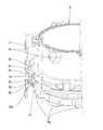
従来、この種の圧縮空気乾燥装置に於ける乾燥容器の取外し機構の技術の一例としては図4に示すWO2007/060882 A1に係る国際公開公報に開示されている。これについて説明すれば、図4は圧縮空気乾燥装置1を示している。圧縮空気乾燥装置1は、例えば大概してコンプレッサの吐出側が接続する入口(図示せず)とメインタンク(図示せず)に接続する出口2と、ガバナー(図示せず)と、ドレンバルブ装置3とを有した例えばアルミニウムやその合金の金属成形品等でなる支持基盤4と、この支持基盤4の例えば上部に、乾燥剤5を充填した乾燥容器6と、この乾燥容器6と、前記アウトレットポート2との間に配置したパージタンク(外側カバー)7とを設けた構成である。該乾燥容器6はその上端周縁に突出部6cを張出し形成している。該突出部6cは所定数個例えば8個周設している。そして該突出部6cの上面に蓋部材6eを取付けボルト6fで固定している。また、該乾燥容器6はその下方に所定数個のパージタンク係止凹陥6dを例えば8個を所定間隔を有して周設している。該パージタンク係止凹陥6dはパージタンク7の下方に所定数例えば8個を所定間隔を有して形成した係止突起7aを係合し該パージタンク7を係止している。Conventionally, an example of a technique for removing a drying container in this type of compressed air drying apparatus is disclosed in International Publication No. WO2007 / 060882 A1 shown in FIG. To explain this, FIG. 4 shows the compressed air drying apparatus 1. The compressed air drying apparatus 1 includes, for example, an inlet (not shown) generally connected to the discharge side of the compressor, an
この圧縮空気乾燥装置1は、コンプレッサから吐出する圧縮空気がインレットポートから流入すると、乾燥容器6を介してパージタンク7からアウトレットポート2へ流れるとき、乾燥容器6の乾燥剤5が圧縮空気内の湿気を吸収する。このとき圧縮空気乾燥装置1はロード運転である。そして圧縮空気乾燥装置1のガバナーは支持基盤4に装着されている。アウトレットポート2に流送する圧縮空気の空気圧がドレンバルブ装置3のドレン弁3aを開弁させる。ドレン弁3aが開弁するとコンプレッサの吐出側を大気に接続するアンロード運転にすると共に乾燥容器6内の圧縮空気を急速に排出し、その後、パージタンク7の圧縮空気により乾燥剤5を再乾燥する。このように、ガバナーの作動から復帰までの間に、圧縮空気乾燥装置1の乾燥動作とアンロード動作を継続する。In this compressed air drying apparatus 1, when the compressed air discharged from the compressor flows in from the inlet port, the
また、圧縮空気乾燥装置1は、例えば支持基盤4が下方に位置させて車両等の車体に取り付けられる。そしてこのインレットポートから供給されるコンプレッサの吐出圧縮空気は、フィルター8を経て孔8aから乾燥容器6内に流入する。このフィルター8により圧縮オイルやダストが除去され乾燥剤5で除湿される。除湿されかつ乾燥した圧縮空気は乾燥容器6の逆止弁6aを開放し通路6bから支持基盤4の部屋4aに貯留され、残部は支持基盤4に備えた逆止弁9からアウトレットポート2を通してメインタンクに貯留する。
図中3bはドレンバルブ装置3のドレン弁3aの開閉を司るピストンである。The compressed air drying device 1 is attached to a vehicle body such as a vehicle with the
In the figure, 3b is a piston for controlling the opening and closing of the
また、ドレン弁3aは乾燥剤5を乾燥処理する時には閉じているが、メインタンク内の圧力が所定値に達するとガバナーからの指令信号によってピストン3bを下げドレン弁3aを開く。水分やオイルを含むドレンはドレン弁3aの開閉に応じて、圧縮空気と一緒に勢いよく外部へ放出される。そのため放出に伴う騒音を低減するため、ドレン弁3aの排出口にはサイレンサ10が設けられている。The
ところで、前記乾燥容器6の最下端部位には支持基盤結合用突起6gを例えば4個を外方に突設しかつ周設してある。一方、前記支持基盤4の上端部位には外側リング部4Aを備え、この外側リング部4Aの内側に前記乾燥容器6を固定するに際して該支持基盤結合用突起6gを上方への移動を停止させるブラケット4bを周設しておりこのブラケット4bの一部に例えば4個の切欠孔4cを周設・形成している。この切欠孔4cは前記乾燥容器6を押込んだときその支持基盤結合用突起6gを挿通し、該乾燥容器6を回動させることにより該支持基盤結合用突起6gがブラケット4bに衝当し該乾燥容器6が上方に離脱することなく、該外側リング部4Aの内側に形成された凹部4dに係合したままとなる。このことにより前記乾燥容器6は支持基盤4に固定される。
尚、図中4Bは支持基盤4の内側リングであり前記乾燥容器6の底部6hを載置・固定する。11はパージタンク7の下端を前記支持基盤4の外側リング部4Aに固定する取付ボルトである。
In the figure, 4B denotes an inner ring of the
従来の技術に於ける前述した圧縮空気乾燥装置に於ける乾燥容器の取外し機構は上述した構成、作用であるので次の問題点が存在した。すなわち、前記乾燥容器6内に充填した乾燥剤5を取替えるときはパージタンク7及び乾燥容器6を支持基盤4から取外す必要がある。一般的に当該圧縮空気乾燥装置1は車両等各種の機器に取付けて使用されるが、例えば車両に搭載したとき、その設置部位が比較的狭隘で例えばパージタンク7の上方に於ける一点鎖線で示すスペース限界高さHが狭く、支持基盤4から取外す手順として該パージタンク7、次に乾燥容器6を取外すことが困難であるという問題点があった。また、支持基盤4から乾燥容器6を取外すためにはパージタンク7及び乾燥容器6を順次取外すこととなり取外すための作業工数が増大するという問題点があった。さらに、パージタンク7及び乾燥容器6を共回りさせることができず簡易かつ迅速に取外しができないという問題点があった。Since the mechanism for removing the drying container in the above-described compressed air drying apparatus in the prior art has the above-described configuration and operation, the following problems exist. That is, when replacing the desiccant 5 filled in the
本発明に係る圧縮空気乾燥装置は叙上の問題点を解決すべく発明したものであり、圧縮空気乾燥装置を狭隘な取付け場所に取付けた場合に於いて、
該圧縮空気乾燥装置に備えた乾燥容器内の乾燥剤を容易に取替えることを目的としたものであって、次の構成、手段から成立する。Compressed air dryingequipment according to the presentinvention has invented to solve the problems in ordination, in the case of mounting the compressed air drying apparatus to narrow mounting location,
The purpose of the present invention is to easily replace the desiccant in the drying container provided in the compressed air drying apparatus.
すなわち、請求項1記載の発明によれば、出口に連なる逆止弁を収容したバルブ収容孔を形成すると共に内側リングでなる中央の縦孔を形成しかつ上面に該内側リングと外側リングとの間に渉って形成されたリング状空間を形成した支持基盤と、前記中央の縦孔に設置したドレンバルブ装置と、前記支持基盤に固定され、底部に乾燥剤を収容し垂直方向の下方又は中間位置に大径の下方突出部を所定数個周設・形成すると共に上部に固定した蓋部材の通路を開閉する逆止弁を備え、該下方突出部の外周面に周設したパージタンク係止凹陥を備えた乾燥容器と、該乾燥容器の下方突出部に係合して固定される係止突起を形成しかつ該乾燥容器の外周を取り囲む円筒状のパージタンクと、を有した圧縮空気乾燥装置に於いて、前記下方突出部の1つないし複数個にクリップ挿入孔を垂直方向に形成し、外方に突出形成しかつ一方、他方が対向した脚部を有したクリップを該クリップ挿入孔に弾圧係入されてなり、前記パージタンクの回転により前記係止突起がクリップの側面に衝当し該パージタンクの回転と共に前記乾燥容器が回転する圧縮空気乾燥装置であって、乾燥処理操作に於いて、乾燥処理すべき圧縮空気が前記支持基盤の側面に設けた入口から入り乾燥剤の中を通過し、蓋部材の通路を開閉する前記逆止弁を開いて前記通路から前記パージタンクの中およびそれに連通すると共に前記支持基盤と該支持基盤の上部に固定された乾燥容器と前記パージタンクとに挟まれた空間に流入し前記支持基盤内の逆止弁から前記出口に排出され、パージ操作に於いて、前記支持基盤と該支持基盤の上部に固定された乾燥容器と前記パージタンクとに挟まれた空間内の圧縮空気は、前記支持基盤と該支持基盤の上部に固定された乾燥容器と前記パージタンクとに挟まれた空間内の内圧力が大気圧よりも高いとき前記乾燥剤を経由して前記ドレンバルブ装置のドレン弁の開動作に応じて外部へ放出されることを特徴とする。That is, according to the first aspect of the present invention, the valve accommodating hole accommodating the check valve connected to the outlet is formed, the central vertical hole formed by the inner ring is formed, and the inner ring and the outer ring are formed on the upper surface. A support base formed with a ring-shaped space formed in between, a drain valve device installed in the central vertical hole, and fixed to the support base, containing a desiccant at the bottom and vertically below or A purge tank unit provided with a check valve that opens and closes a passage of a lid member fixed to the upper portion, and has a predetermined number of large-diameter downward protrusions formed at an intermediate position. Compressed air having a drying container having a concave recess, and a cylindrical purge tank that forms a locking projection that engages and is fixed to a downward projecting portion of the drying container and surrounds the outer periphery of the drying container In the drying apparatus, 1 Or a plurality of clip insertion holes formed in a vertical direction, projecting outwardly, and having a leg portion opposite to the other, the clip insertion hole being elastically engaged with the clip insertion hole, A compressed air drying device in which the locking projections abut against a side surface of the clip by rotation and the drying container rotates with rotation of the purge tank, and in the drying processing operation, the compressed air to be dried is supported by the support The check valve for opening and closing the passage of the lid member is opened through the inlet provided on the side surface of the base, opens and closes the passage of the lid member, and communicates with and into the purge tank from the passage. It is discharged from the check valve in the support base to flow into the space sandwiched between the purge tank and the drying vessel, which is fixed to the upper portion of base to the outlet, in the purging operation,the support base and said supporting Space compressed air in the space sandwiched between the purge tank and the drying vessel which is secured to the top of thebase, which is sandwiched the support baseand the upper which is fixed to the drying vessel of the support base and to said purge tank When the internal pressure is higher than the atmospheric pressure, the internal pressure is discharged to the outside via the desiccant according to the opening operation of the drain valve of the drain valve device.
請求項2記載の発明によれば、請求項1記載の発明に於いて、前記クリップが薄板状の略V字形状であって、一方、他方の脚部で構成されかつ一方、他方の脚部の下端を外方に突出形成したことを特徴とする。According to a second aspect of the present invention, in the first aspect of the present invention, the clip has a thin plate-like substantially V shape, and is composed of one leg and the other leg. It is characterized in that the lower end of the projection protrudes outward.
本発明に係る圧縮空気乾燥装置は上述した構成を有するので次の効果がある。Compressed air dryingequipment according to the present inventionhas the following advantages because it has the above-described configuration.
すなわち、請求項1に記載した本発明によれば、出口に連なる逆止弁を収容したバルブ収容孔を形成すると共に内側リングでなる中央の縦孔を形成しかつ上面に該内側リングと外側リングとの間に渉って形成されたリング状空間を形成した支持基盤と、前記中央の縦孔に設置したドレンバルブ装置と、前記支持基盤に固定され、底部に乾燥剤を収容し垂直方向の下方又は中間位置に大径の下方突出部を所定数個周設・形成すると共に上部に固定した蓋部材の通路を開閉する逆止弁を備え、該下方突出部の外周面に周設したパージタンク係止凹陥を備えた乾燥容器と、該乾燥容器の下方突出部に係合して固定される係止突起を形成しかつ該乾燥容器の外周を取り囲む円筒状のパージタンクと、を有した圧縮空気乾燥装置に於いて、前記下方突出部の1つないし複数個にクリップ挿入孔を垂直方向に形成し、外方に突出形成しかつ一方、他方が対向した脚部を有したクリップを該クリップ挿入孔に弾圧係入されてなり、前記パージタンクの回転により前記係止突起がクリップの側面に衝当し該パージタンクの回転と共に前記乾燥容器が回転する圧縮空気乾燥装置であって、乾燥処理操作に於いて、乾燥処理すべき圧縮空気が前記支持基盤の側面に設けた入口から入り乾燥剤の中を通過し、蓋部材の通路を開閉する前記逆止弁を開いて前記通路から前記パージタンクの中およびそれに連通すると共に前記支持基盤と該支持基盤の上部に固定された乾燥容器と前記パージタンクとに挟まれた空間に流入し前記支持基盤内の逆止弁から前記出口に排出され、パージ操作に於いて、前記支持基盤と該支持基盤の上部に固定された乾燥容器と前記パージタンクとに挟まれた空間内の圧縮空気は、前記支持基盤と該支持基盤の上部に固定された乾燥容器と前記パージタンクとに挟まれた空間内の内圧力が大気圧よりも高いとき前記乾燥剤を経由して前記ドレンバルブ装置のドレン弁の開動作に応じて外部へ放出されることを特徴とする圧縮空気乾燥装置を提供する。
このような構成としたので、当該圧縮空気乾燥装置を例えば車両に搭載したとき、その設置部位が比較的狭隘で例えばパージタンクの上方に於ける空間が狭くても、乾燥容器とパージタンクを共回りさせることができるので乾燥容器とパージタンクを一括して迅速に支持基盤からとりはずることができるという効果があり、支持基盤から乾燥容器を取外すための作業工数を削減することができるという効果がある。That is, according to the first aspect of the present invention, the valve accommodating hole accommodating the check valve connected to the outlet is formed, the central vertical hole formed by the inner ring is formed, and the inner ring and the outer ring are formed on the upper surface. And a support base that forms a ring-shaped space formed between them, a drain valve device installed in the central vertical hole, and is fixed to the support base and accommodates a desiccant at the bottom and has a vertical direction. A purge having a check valve that opens and closes a passage of a lid member fixed to the upper portion and has a predetermined number of large-diameter downward projecting portions formed in a lower or intermediate position. A drying container having a tank locking recess, and a cylindrical purge tank that forms a locking projection that engages and is fixed to a downward projecting portion of the drying container and surrounds the outer periphery of the drying container. In the compressed air drying apparatus, the downward protrusion A clip insertion hole is formed vertically in one or more of the first and second protrusions, and a clip having an outwardly protruding leg and the other side is opposed to the clip insertion hole. A compressed air drying apparatus in which the latching protrusion hits a side surface of a clip by rotation of a purge tank, and the drying container rotates together with rotation of the purge tank. Enters the desiccant through an inlet provided on the side surface of the support base, opens the check valve that opens and closes the passage of the lid member, and communicates with and into the purge tank from the passage. and is discharged to the outlet from the top which is fixed to the drying vessel support base and flows into the sandwiched between the purge tank space check valve in said support base, in the purging operation,the support base The compressed air in the upper which is fixed to the drying vessel support base within said sandwiched between the purge tank spaceis sandwiched the support baseand the upper which is fixed to the drying vessel of the support base and to said purge tank providingcompressed air dryingequipment whose inner pressure, characterized in that it is discharged to the outside in response to the opening operation of the via the desiccant is higher than the atmospheric pressure drain valve of the drain valve device in the space has To do.
With this configuration, when the compressed air drying apparatus is mounted on a vehicle, for example, the drying container and the purge tank are shared even if the installation site is relatively narrow and the space above the purge tank is small, for example. Since it can be rotated, there is an effect that the drying container and the purge tank can be quickly removed from the support base collectively, and the work man-hour for removing the drying container from the support base can be reduced. There is.
請求項2に記載した本発明によれば、前記クリップが薄板状の略V字形状であって、一方、他方の脚部で構成されかつ一方、他方の脚部の下端を外方に突出形成したことを特徴とする請求項1記載の圧縮空気乾燥装置を提供する。
このような構成としたので、請求項1記載の発明の効果に加えて、クリップにより乾燥容器をパージタンクと共回りさせて支持基盤から容易に外すことが可能となり併せて、該クリップがクリップ挿入用孔から離脱しないという効果がある。According to the second aspect of the present invention, the clip has a thin plate-like substantially V shape, and is formed of one leg portion on the other side, and the lower end of the other leg portion is formed to project outward. it was to providea compressed air dryingequipment according to claim 1, wherein.
With this configuration, in addition to the effect of the first aspect of the invention, the clip can be easily removed from the support base by rotating the drying container together with the purge tank, and the clip is inserted into the clip. There is an effect that it does not leave the hole.
以下、本発明に係る圧縮空気乾燥装置に於ける実施の形態について添付図面に基づき詳細に説明する。
図1は本発明に係る圧縮空気乾燥装置の実施の形態の一例を示す垂直断面図である。図2は図1に示す当該圧縮空気乾燥装置の要部を拡大した斜視図である。図3は本発明に係る圧縮空気乾燥装置を構成するクリップを示す図面であって、(a)は正面図、(b)は右側面図である。Hereinafter,the compressed air dryequipment for the form of in embodiment will be described in detail with reference to the accompanying drawings according to the present invention.
Figure 1 is a vertical sectional view showing an example of an embodimentof the compressed air dryingequipment according to the present invention. Figure 2 is an enlarged perspective view of a main portionof the compressed air dryingequipment shown in FIG. Figure 3 is a view showing a clip constitutinga compressed air dryingequipment according to the present invention, (a) is a front view, (b) is a right side view.
圧縮空気乾燥装置1Aの底部には肉厚な支持基盤4がある。支持基盤4は、アルミニウムあるいはその合金などからなる金属成型品である。支持基盤4の一方の側面には空気圧縮機(図示せず)の吐出口に連通される入口(図示せず)があり、他方の側面にはメインタンク(図示せず)に連通される出口2を設けている。これら出口2および入口は、配管接続口となり、例えばねじ孔から構成される。There is a
空気圧縮機(図示せず)の吐出口に連通される入口は、径方向に伸びる入口孔から中央の縦孔4eを通し支持基盤4の上面に連通している。また、出口2は、バルブ収容孔9aを通して支持基盤4の上面に連通している。出口2側のバルブ収容孔9aには、支持基盤4の上面から出口2に向かう位置にバルブ収容孔9aの逆止弁9つまり支持基盤4内の逆止弁9が入っている。The inlet communicated with the discharge port of the air compressor (not shown) communicates with the upper surface of the
支持基盤4は、下面側にハブ状の突起部4fを一体に備えているのに対し、上面側には、内側リング部4Bおよび外側リング部4Aを同心状に備えている。外側リング部4Aは、内側リング部4Bに比べて背が高くしかも肉厚状に構成している。内側リング部4Bと外側リング部4Aとの間にわたって支持基盤4の上面は大きくえぐられ、そこに空間、具体的にはリング状空間、つまり部屋4aが形成されている。この部屋4aは、乾燥処理を終えた圧縮空気を貯える空間として利用される。したがって、前記逆止弁9を収容したバルブ収容孔9aは、部屋4aに開口する。The
圧縮空気乾燥装置1Aは、上述の支持基盤4のほか、支持基盤4の上に位置しかつ固定された乾燥容器6および外側カバーとしてのパージタンク7を備える。乾燥容器6は、内部に粒状の乾燥剤5を収容した容器である。また、パージタンク7は、円筒状であって乾燥容器6の外周を取り囲み、その乾燥容器6との間に圧縮空気を貯える第1の部屋つまりパージタンクの中7bを区画するカバーである。パージタンク7と乾燥容器6は互いに嵌り合う。嵌り合う部分には、密閉するためのシールリング7cを設けている。In addition to the
そして、該乾燥容器6はその上端周縁に突出部6cを張出し形成している。該突出部6cは所定数個例えば8個周設している。そして該突出部6cの上面に蓋部材6eを取付けボルト6fで固定している。また、該乾燥容器6はその垂直方向の下方又は中間位置に形成した大径な下方突出部6iの外周面状に所定数例えば4個のパージタンク係止凹陥6dを周設している。該パージタンク係止凹陥6dはパージタンク7の下方に所定数、例えば4個をプレス加工等で形成した係止突起7aを係合し該パージタンク7を係止している。The drying
乾燥容器6の大径な下方突出部6iは、下面にリング状空間6jを備える。リング状空間6jは、支持基盤4側の内部空間、具体的にはリング状空間、つまり部屋4aと一緒になって、乾燥処理を終えた圧縮空気を貯える第2の部屋つまりリング状部屋6kを区画する。圧縮空気を貯える第2の部屋6kと圧縮空気を貯える第1の部屋つまりパージタンクの中7bとは、複数の連通孔(図示せず)を通して互いに連通する。The large-diameter downward protruding
大径な下方突出部6iのリング状空間6jは、幅が広い部分と幅が狭い部分とが連続した形態である。それに応じ、乾燥容器6の容器内部には、底部に小容積の収容部分があり、その上に大容積の収容部分がある。底部の小容積の収容部分にはフィルタエレメント8が充填され、その上の大容積の収容部分に再生可能な粒状の乾燥剤5が充填されている。容器内部の乾燥剤5およびフィルタエレメント8は、複数の取付けボルト6fをゆるめて乾燥容器6の上部の蓋部材6eを取り外すことによって交換可能である。蓋部材6eには、逆止弁6aが閉じる比較的に大きな通路6bがある。また、蓋部材6eの下には、粒状の乾燥剤5を適度に充填するためのコイルバネ6mを巻装してある。The ring-shaped space 6j of the large-diameter downward protruding
そこで、乾燥処理すべき圧縮空気は、入口から入りまずフィルタエレメント8によってコンプレッサオイルやダストが除去され、ついで乾燥剤5の中を通過することにより除湿される。除湿され乾燥した圧縮空気は、蓋部材6eの通路を開閉する逆止弁6aを開いて通路6bからパージタンク7の圧縮空気を貯える第1の部屋つまりパージタンクの中7b、およびそれに連通する圧縮空気を貯える第2の部屋つまりリング状部屋6kに流入する。流入した圧縮空気は、一部が再生用として圧縮空気を貯える第1の部屋つまりパージタンクの中7bおよび圧縮空気を貯える第2の部屋つまりリング状部屋6k内に貯えられ、残りは支持基盤4内の逆止弁9から出口2を通して外部のメインタンク内に貯えられる。メインタンク内の圧縮空気は、たとえばエアブレーキ系統の各機器の作動に利用される。Therefore, the compressed air to be dried does not enter from the inlet, the compressor oil and dust are removed by the
支持基盤4の中央の縦孔4eの中に、ドレンバルブ装置3が設置されている。ドレンバルブ装置3は、ドレンを排出するためのドレン弁3a及びピストン3bを有している。そして該ドレン弁3aは乾燥剤5の再生サイクル時における外気への開放弁を兼ねている。ドレン弁3aは、乾燥剤5を乾燥処理する時には閉じているが、メインタンク内の圧力が所定値に達すると、プレッシャガバナ(図示せず)からの指令信号によってピストン3bを下げ弁を開く。水分やオイルを含むドレンは、ドレン弁3aの開閉に応じて、圧縮空気と一緒に勢いよく外部へ放出される。そのため、放出に伴う騒音を低減するため、ドレン弁3aの排出口にはサイレンサ10が設けられる。A
圧縮空気乾燥装置1Aでは乾燥容器6とパージタンク7とを取付け及び取外し可能に取付けると共に、乾燥容器6とパージタンク7とを取付けボルト11により支持基盤4に取付け及び取外し可能に取付けるように構成する。In the compressed
次に乾燥容器6内に充填された乾燥剤5が経年変化等により使用不能となった場合、前記パージタンク7及び乾燥容器6を支持基盤4から取外す必要がある。かかる場合パージタンク7及び乾燥容器6を共回りさせて支持基盤4から取外すことができれば作業工数を大幅に削減できる等便利である。そこで該乾燥容器6の取外し機構としてのクリップ12等について説明する。Next, when the
当該クリップ12は図3(a)、(b)に示すように正面形状が略V字形バネ板であって、その板厚が約1(mm)程度の薄板状で構成され、金属材料又は樹脂材料等で成形される。該クリップ12は円弧状頂点部12aと、この円弧状頂点部12aから左・右に延出形成した脚部12b、12bとを備えている。該脚部12b、12bはいずれもその一方、他方の下端12c、12cは外方に突出形成している。すなわち、適宜傾斜を有して張出し形成している。また該円弧状頂点部12aと一方、他方の下端12c、12cとの間の中間位置に略山形状突起12d、12dを形成している。そして該クリップ12は弾性機能を備え、前記一方、他方の下端12c、12cを対向しかつ接近させるように圧縮し、また互いに離反するように拡開する。As shown in FIGS. 3 (a) and 3 (b), the
該クリップ12は側面形状が図3(b)に示すように例えば略矩形状に形成されている。その設定寸法としては例えば縦長が脚部12bの長さであって、約30(mm)、幅長が約10(mm)程度が好適である。As shown in FIG. 3B, the
ここに於いて、図2に基づき前記クリップ12が前記乾燥容器6に装着された状態を説明する。該乾燥容器6は垂直方向の下方又は中間位置に大径な下方突出部6iを所定数個例えば4個を周設・形成している。該下方突出部6iはその外周面に所定数個、例えば4個のパージタンク係止凹陥6dを周設している。このため、該パージタンク係止凹陥6dはそのため上縁6nと下縁6pとその中間に位置する溝6qとで構成される。Here, a state where the
前記乾燥容器6に形成した下方突出部6iの1つないし複数個に前述したクリップ12を装着するためのクリップ挿入用孔6rを垂直方向に形成する。該クリップ挿入用孔6rは下方突出部6iの上面から下面まで貫通形成すると共に該クリップ12をクリップ挿入用孔6rに装着した際前記パージタンク7の係止突起7aが該クリップ12の側面に衝当するように形成する。そして、作業者が図3(a)に示すクリップ12の一方、他方の下端12c、12cを手で互いを閉止するように圧接しその円弧状頂点部12aを前記クリップ挿入用孔6rの下方から上方に向って押込んで該クリップ挿入用孔6rに装着する。挿入された該クリップ12はその性質上円弧状頂点部12aを基点として一方、他方脚部12b、12bが弾発し又は復元作用を呈し、該クリップ12の一方、他方脚部12b、12bはクリップ挿入用孔6rに挿入することによりクリップ挿入用孔6rの両側面に圧着し、該クリップ挿入用孔6rから脱落することがない。特に該クリップ12の一方、他方の下端12c、12cは適宜斜面を形成し外方に張出しているので該クリップ12がクリップ挿入用孔6rの上面から抜出すことがなくクリップ挿入用孔6r内に安定して保持される。A
次に本発明に係る圧縮空気乾燥装置についてその組立手順やパージタンク7及び乾燥容器6の取外し機構の動作等を説明する。
前記乾燥容器6を支持基盤4に取付けるときは、該乾燥容器6の支持基盤結合用突起6gを支持基盤4の切欠孔4cに挿通し該乾燥容器6を回動する。該支持基盤結合用突起6gはブラケット4bの下面に入り込み、該支持基盤結合用突起6gは外側リング部4Aの凹部4dに係合した状態になる。このときフィルタエレメント8を装置した乾燥容器6の底部6hは支持基盤4の内側リング部4Bに嵌着している。Next, the assembly procedure of the compressed air drying apparatus according to the present invention, the operation of the removal mechanism of the
When the drying
そしてパージタンク7の開口下縁7dを支持基盤4の外側リング部4Aの外周に嵌合する。このとき外側リング部4Aに備えたシールリング7cはパージタンク7と支持基盤4を密封する機能を有する。該パージタンク7の開口下縁7dには切欠きを形成しこの切欠きに取付けボルト11を螺合しパージタンク7と支持基盤4を固定する。Then, the
次に、乾燥容器6内に充填された乾燥剤5が経年変化等により使用不能となった場合作業者は前記取付けボルト11をパージタンク7の開口下縁7dから取外し、前記パージタンク7を左方向又は右方向に回転させる。そして図2に示すように該パージタンク7の係止突起7aが予め乾燥容器6に装着しているクリップ12の一方又は他方の側面12eに衝当する。これにより該パージタンク7を強制的に回転させるとこれに合わせて該乾燥容器6が回転する。すなわち、パージタンク7と乾燥容器6は共回りすることとなる。該乾燥容器6の回転に従い支持基盤結合用突起6gがブラケット4bの下面を回転し支持基盤4の切欠孔4cの位置に移動しパージタンク7と乾燥容器6を一緒に引上げることができる。この状態に於けるパージタンク7と乾燥容器6は図1の仮想線で示している。従って上方に引上げたときパージタンク7の頂部が一点鎖線で示すスペース限界高さHを越えることなく乾燥容器6内の乾燥剤5を容易に取替えることが可能となる。Next, when the
1A 圧縮空気乾燥装置
2 出口
3 ドレンバルブ装置
3a ドレン弁
4 支持基盤
4A 外側リング部
4B 内側リング部
4a 部屋(リング状空間)
4b ブラケット
4c 切欠孔
4d 凹部
4e 縦孔
4f 突起部
5 乾燥剤
6 乾燥容器
6a 蓋部材の逆止弁
6b 通路
6c 突出部
6d パージタンク係止凹陥
6e 蓋部材
6f 取付けボルト
6g 支持基盤結合用突起
6h 底部
6i 下方突出部
6j リング状空間
6k 第2の部屋(リング状部屋)
6m コイルバネ
6n 上縁
6p 下縁
6q 溝
6r クリップ挿入用孔
7 パージタンク
7a 係止突起
7b 第1の部屋(パージタンクの中)
7c シールリング
7d 開口下縁
8 フィルタエレメント
9 逆止弁
9a バルブ収容孔9a
11 取付けボルト
12 クリップ
12a 円弧状頂点部
12b 脚部
12c 下端
12d 略山形状突起
12e 側面1A Compressed
6
11 mounting
Claims (2)
Translated fromJapanesePriority Applications (1)
| Application Number | Priority Date | Filing Date | Title |
|---|---|---|---|
| JP2008194870AJP5435766B2 (en) | 2008-07-29 | 2008-07-29 | Compressed air dryer |
Applications Claiming Priority (1)
| Application Number | Priority Date | Filing Date | Title |
|---|---|---|---|
| JP2008194870AJP5435766B2 (en) | 2008-07-29 | 2008-07-29 | Compressed air dryer |
Publications (2)
| Publication Number | Publication Date |
|---|---|
| JP2010029789A JP2010029789A (en) | 2010-02-12 |
| JP5435766B2true JP5435766B2 (en) | 2014-03-05 |
Family
ID=41734932
Family Applications (1)
| Application Number | Title | Priority Date | Filing Date |
|---|---|---|---|
| JP2008194870AActiveJP5435766B2 (en) | 2008-07-29 | 2008-07-29 | Compressed air dryer |
Country Status (1)
| Country | Link |
|---|---|
| JP (1) | JP5435766B2 (en) |
Family Cites Families (2)
| Publication number | Priority date | Publication date | Assignee | Title |
|---|---|---|---|---|
| US5595588A (en)* | 1995-07-24 | 1997-01-21 | Alliedsignal Truck Brake Systems Co. | Air dryer cartridge mounting system |
| JP4953417B2 (en)* | 2005-11-22 | 2012-06-13 | ナブテスコオートモーティブ株式会社 | Air dryer |
- 2008
- 2008-07-29JPJP2008194870Apatent/JP5435766B2/enactiveActive
Also Published As
| Publication number | Publication date |
|---|---|
| JP2010029789A (en) | 2010-02-12 |
Similar Documents
| Publication | Publication Date | Title |
|---|---|---|
| JP6373757B2 (en) | Compressed air dryer | |
| CN102574051B (en) | Structure of the outer cover in the air drying device | |
| US6878194B2 (en) | Remote purge drying unit for compressed gas | |
| US7691163B2 (en) | Vehicle air dryer | |
| WO2014006928A1 (en) | Oil separator | |
| US8852327B1 (en) | Air dryer cartridge with integrated check valve | |
| JP5464687B2 (en) | Compressed air dryer | |
| WO2007060883A1 (en) | Air drier | |
| WO2015105185A1 (en) | Compressed air drying device | |
| JP5435766B2 (en) | Compressed air dryer | |
| JP6144154B2 (en) | Compressed air dryer | |
| WO2015088027A1 (en) | Compressed air-drying device | |
| KR100623585B1 (en) | Vehicle air brake system | |
| JP5435767B2 (en) | Compressed air dryer | |
| WO2015182583A1 (en) | Air drier | |
| US8906144B2 (en) | Compact adsorption dryer | |
| JPH0639782Y2 (en) | Compressed air pressure source device | |
| JPH067777Y2 (en) | Air dryer equipment | |
| JP2021137808A (en) | Oil separator | |
| JP6567871B2 (en) | Oil separator | |
| KR940000928Y1 (en) | Drying apparatus by the compressed air | |
| JPH0751147Y2 (en) | Dehumidifier | |
| JP2014024030A (en) | Compression air dryer | |
| JP2570431Y2 (en) | Dehumidifier | |
| JP2023071800A (en) | oil separator |
Legal Events
| Date | Code | Title | Description |
|---|---|---|---|
| A711 | Notification of change in applicant | Free format text:JAPANESE INTERMEDIATE CODE: A711 Effective date:20100308 | |
| A625 | Written request for application examination (by other person) | Free format text:JAPANESE INTERMEDIATE CODE: A625 Effective date:20110606 | |
| RD02 | Notification of acceptance of power of attorney | Free format text:JAPANESE INTERMEDIATE CODE: A7422 Effective date:20110912 | |
| A977 | Report on retrieval | Free format text:JAPANESE INTERMEDIATE CODE: A971007 Effective date:20121214 | |
| A131 | Notification of reasons for refusal | Free format text:JAPANESE INTERMEDIATE CODE: A131 Effective date:20121220 | |
| A521 | Request for written amendment filed | Free format text:JAPANESE INTERMEDIATE CODE: A523 Effective date:20130214 | |
| A871 | Explanation of circumstances concerning accelerated examination | Free format text:JAPANESE INTERMEDIATE CODE: A871 Effective date:20130612 | |
| A975 | Report on accelerated examination | Free format text:JAPANESE INTERMEDIATE CODE: A971005 Effective date:20130627 | |
| A131 | Notification of reasons for refusal | Free format text:JAPANESE INTERMEDIATE CODE: A131 Effective date:20130702 | |
| A521 | Request for written amendment filed | Free format text:JAPANESE INTERMEDIATE CODE: A523 Effective date:20130821 | |
| A131 | Notification of reasons for refusal | Free format text:JAPANESE INTERMEDIATE CODE: A131 Effective date:20130927 | |
| A521 | Request for written amendment filed | Free format text:JAPANESE INTERMEDIATE CODE: A523 Effective date:20131106 | |
| TRDD | Decision of grant or rejection written | ||
| A01 | Written decision to grant a patent or to grant a registration (utility model) | Free format text:JAPANESE INTERMEDIATE CODE: A01 Effective date:20131206 | |
| A61 | First payment of annual fees (during grant procedure) | Free format text:JAPANESE INTERMEDIATE CODE: A61 Effective date:20131209 | |
| R150 | Certificate of patent or registration of utility model | Ref document number:5435766 Country of ref document:JP Free format text:JAPANESE INTERMEDIATE CODE: R150 Free format text:JAPANESE INTERMEDIATE CODE: R150 | |
| R250 | Receipt of annual fees | Free format text:JAPANESE INTERMEDIATE CODE: R250 | |
| R250 | Receipt of annual fees | Free format text:JAPANESE INTERMEDIATE CODE: R250 | |
| R250 | Receipt of annual fees | Free format text:JAPANESE INTERMEDIATE CODE: R250 | |
| R250 | Receipt of annual fees | Free format text:JAPANESE INTERMEDIATE CODE: R250 | |
| R250 | Receipt of annual fees | Free format text:JAPANESE INTERMEDIATE CODE: R250 | |
| R250 | Receipt of annual fees | Free format text:JAPANESE INTERMEDIATE CODE: R250 | |
| R250 | Receipt of annual fees | Free format text:JAPANESE INTERMEDIATE CODE: R250 | |
| R250 | Receipt of annual fees | Free format text:JAPANESE INTERMEDIATE CODE: R250 | |
| R250 | Receipt of annual fees | Free format text:JAPANESE INTERMEDIATE CODE: R250 |