JP5434929B2 - I/O Bus System - Google Patents
I/O Bus SystemDownload PDFInfo
- Publication number
- JP5434929B2 JP5434929B2JP2010537754AJP2010537754AJP5434929B2JP 5434929 B2JP5434929 B2JP 5434929B2JP 2010537754 AJP2010537754 AJP 2010537754AJP 2010537754 AJP2010537754 AJP 2010537754AJP 5434929 B2JP5434929 B2JP 5434929B2
- Authority
- JP
- Japan
- Prior art keywords
- network
- pci express
- bridge
- host
- packet
- Prior art date
- Legal status (The legal status is an assumption and is not a legal conclusion. Google has not performed a legal analysis and makes no representation as to the accuracy of the status listed.)
- Active
Links
Images


Classifications
- G—PHYSICS
- G06—COMPUTING OR CALCULATING; COUNTING
- G06F—ELECTRIC DIGITAL DATA PROCESSING
- G06F13/00—Interconnection of, or transfer of information or other signals between, memories, input/output devices or central processing units
- G06F13/38—Information transfer, e.g. on bus
- G06F13/40—Bus structure
- G06F13/4004—Coupling between buses
- G06F13/4022—Coupling between buses using switching circuits, e.g. switching matrix, connection or expansion network
- G—PHYSICS
- G06—COMPUTING OR CALCULATING; COUNTING
- G06F—ELECTRIC DIGITAL DATA PROCESSING
- G06F13/00—Interconnection of, or transfer of information or other signals between, memories, input/output devices or central processing units
- G06F13/38—Information transfer, e.g. on bus
- G06F13/40—Bus structure
- G06F13/4004—Coupling between buses
- G06F13/4027—Coupling between buses using bus bridges
- G06F13/404—Coupling between buses using bus bridges with address mapping
Landscapes
- Engineering & Computer Science (AREA)
- General Engineering & Computer Science (AREA)
- Theoretical Computer Science (AREA)
- Physics & Mathematics (AREA)
- Computer Hardware Design (AREA)
- General Physics & Mathematics (AREA)
- Mathematical Physics (AREA)
- Bus Control (AREA)
- Small-Scale Networks (AREA)
- Data Exchanges In Wide-Area Networks (AREA)
Description
Translated fromJapanese本発明はI/Oバスに関し、特にI/Oバスシステム、I/Oバスシステム制御方法、およびI/Oバスシステム制御用プログラム記録媒体に関する。The present invention relates to an I/O bus, and in particular to an I/O bus system, an I/O bus system control method, and a program recording medium for controlling an I/O bus system.
現在広く普及している情報処理装置の多くに、I/Oバス(例えば、PCIバス)が備えられている。I/Oバスにおけるデータ処理の高速化や、扱われるデータの大容量化などに伴って、従来のI/Oバス規格に変わる新たなI/Oバス規格に関する技術が提唱されてきた。例えば、特開2007−219873号公報に記載されているような、その新たなI/Oバス規格に従って設計されたI/Oバスシステムに関する技術が知られている。Many of the information processing devices currently in widespread use are equipped with an I/O bus (e.g., a PCI bus). As data processing speeds on I/O buses increase and the volume of data handled increases, technology related to new I/O bus standards to replace conventional I/O bus standards has been proposed. For example, technology related to an I/O bus system designed in accordance with the new I/O bus standard is known, as described in JP 2007-219873 A.
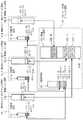
図1は、その特開2007−219873号公報に記載されているI/Oバスシステムの構成を示すブロック図である。そのI/Oバスシステムは、ホスト101と、PCIエクスプレススイッチ105と、I/O103とを含んでいる。Figure 1 is a block diagram showing the configuration of the I/O bus system described in JP 2007-219873 A. The I/O bus system includes a host 101, a
ホスト101は、CPU111と、メモリ113と、ルートコンプレックス112とを含んでいる。ルートコンプレックス112は、CPU111と、メモリ113と、PCIエクスプレススイッチ105とを相互に接続している。I/O103は、ホスト101のいずれかに、その使用権が割り当てられる。また、I/O103のホスト101への割り当ては変更可能である。The host 101 includes a
PCIエクスプレススイッチ105は、上流PCIエクスプレス−ネットワークブリッジ121と、ネットワークスイッチ122と、下流PCIエクスプレス−ネットワークブリッジ125と、システムマネージャ151とを含んでいる。上流PCIエクスプレス−ネットワークブリッジ121は、ホスト101側でPCIエクスプレスバスとネットワークとをブリッジする。ネットワークスイッチ122は、ネットワークパケットを転送する。下流PCIエクスプレス−ネットワークブリッジ125は、I/O103側でネットワークとPCIエクスプレスバスをブリッジする。システムマネージャ151は、上流PCIエクスプレス−ネットワークブリッジ121と下流PCIエクスプレス−ネットワークブリッジ125との接続を制御し、I/O103のホスト101への割り当てを設定する。The
また、上流PCIエクスプレス−ネットワークブリッジ121は、複数の下流PCIエクスプレス−ネットワークブリッジ125に接続されている。そして、上流PCIエクスプレス−ネットワークブリッジ121は、ルートコンプレックス112から、I/O103あてのI/Oパケットを受信し、その受信したI/Oパケットをネットワークパケットにカプセル化してネットワークスイッチ122に転送する。このとき、上流PCIエクスプレス−ネットワークブリッジ121は、そのカプセル化したパケットのあて先に、元のI/Oパケットのあて先であるI/O103に接続されている下流PCIエクスプレス−ネットワークブリッジ125のネットワークアドレスを記載する。The upstream PCI Express-network bridge 121 is also connected to a plurality of downstream PCI Express-
また、上流PCIエクスプレス−ネットワークブリッジ121は、ネットワークスイッチ122から、ホスト101あてのI/Oパケットがカプセル化されたネットワークパケットを受信する。上流PCIエクスプレス−ネットワークブリッジ121は、受信したネットワークパケットをデカプセル化し、ルートコンプレックス112に送信する。In addition, the upstream PCI Express-network bridge 121 receives a network packet in which an I/O packet addressed to the host 101 is encapsulated from the
下流PCIエクスプレス−ネットワークブリッジ125は、1つの上流PCIエクスプレス−ネットワークブリッジ121に接続されている。下流PCIエクスプレス−ネットワークブリッジ125は、I/O103から接続する上流PCIエクスプレス−ネットワークブリッジ121に対応するホスト101あてのI/Oパケットを受信し、受信したI/Oパケットをネットワークパケットにカプセル化し、カプセル化したパケットのあて先に、I/Oパケットのあて先ホスト101が接続する上流PCIエクスプレス−ネットワークブリッジ121のネットワークアドレスを記載し、ネットワークスイッチ122に転送する。また、ネットワークスイッチ122からI/O103あてのI/Oパケットがカプセル化されたネットワークパケットを受信し、I/Oパケットをデカプセル化し、I/O103に送信する。The downstream PCI Express-
図2はホスト101−1のアドレス空間115−1を示す図である。ここではI/O103−1〜I/O103−Mが全てホスト101−1に割り当てられている場合を説明する。ホスト101のアドレス空間115は、バス番号、デバイス番号、ファンクション番号の3つの番号を組とするID番号の空間であるID番号空間1151と、2のべき乗の容量を持つ物理メモリ空間1152とを含む。ホスト101が使用するI/O103のアドレスは、ID番号空間1151と、物理メモリ空間1152とにマップされる。ここでは、I/O103−1〜I/O103−Mが、それぞれID番号空間1151−1のI/O103−1〜I/O103−Mのマップ1511−1〜マップ1511−Mと、物理メモリ空間1152−1のI/O103−1〜I/O103−Mのマップ1521−1〜マップ1521−Mとにマップされている。Figure 2 is a diagram showing address space 115-1 of host 101-1. Here, we explain the case where I/O 103-1 to I/O 103-M are all assigned to host 101-1. Address space 115 of host 101 includes ID number space 1151, which is a space of ID numbers consisting of a set of three numbers: bus number, device number, and function number, and physical memory space 1152, which has a capacity that is a power of 2. The address of I/
このような構成を有する従来のI/Oバスシステムは次のように動作する。システムマネージャ151は、下流PCIエクスプレス−ネットワークブリッジ125がどの上流PCIエクスプレス−ネットワークブリッジ121と接続するか、制御パケットを下流PCIエクスプレス−ネットワークブリッジ125に送信することで制御する。I/O103は、下流PCIエクスプレス−ネットワークブリッジ125が接続する上流PCIエクスプレス−ネットワークブリッジ121と接続したホスト101に割り当てられる。A conventional I/O bus system having such a configuration operates as follows. The system manager 151 controls which upstream PCI Express-network bridge 121 the downstream PCI Express-
上流PCIエクスプレス−ネットワークブリッジ121と下流PCIエクスプレス−ネットワークブリッジ125とは、ホスト101と、ホスト101に割り当てられたI/O103との間で送受信されるI/Oパケットをネットワークパケットにカプセル化し、上流PCIエクスプレス−ネットワークブリッジ121と下流PCIエクスプレス−ネットワークブリッジ125との間をトンネリングする。The upstream PCI Express-network bridge 121 and the downstream PCI Express-
ホスト101は、上流PCIエクスプレス−ネットワークブリッジ121が標準に準拠したPCIエクスプレススイッチ内部の上流PCI−PCIブリッジであり、下流PCIエクスプレス−ネットワークブリッジ125がPCIエクスプレススイッチ内部の下流PCI−PCIブリッジであると認識し、それにより、上流PCIエクスプレス−ネットワークブリッジ25と、下流PCIエクスプレス−ネットワークブリッジ21との間の領域が、標準に準拠したPCIエクスプレススイッチであると認識する。このため、従来のI/Oバスシステムでは、ホスト101に特別なソフトウェアを必要とすることなく、ホスト101に対するI/O103の割り当てを自由に変更できる。The host 101 recognizes that the upstream PCI Express-network bridge 121 is an upstream PCI-PCI bridge inside a standard-compliant PCI Express switch, and the downstream PCI Express-
関連するI/Oバスシステムは、下流PCIエクスプレス−ネットワークブリッジが1つの上流PCIエクスプレス−ネットワークブリッジと接続し、I/Oパケットのトンネリングを行うことを想定して設計されている。また、I/Oリソースが1つのホストに占有されることを想定して設計されている。そのため、I/Oリソースが同時に2つ以上のホストから共有できないことがある。The related I/O bus system is designed on the assumption that a downstream PCI Express-network bridge connects to one upstream PCI Express-network bridge and performs tunneling of I/O packets. It is also designed on the assumption that I/O resources are dedicated to one host. Therefore, I/O resources may not be shared by two or more hosts at the same time.
さらに、関連するI/Oバスシステムは、下流PCIエクスプレス−ネットワークブリッジが同時に2つ以上の上流PCIエクスプレス−ネットワークブリッジと接続してI/Oパケットのトンネリングを行えないことがある。Additionally, the associated I/O bus system may not allow a downstream PCI Express-to-network bridge to simultaneously connect to two or more upstream PCI Express-to-network bridges for tunneling I/O packets.
本発明の目的は、I/Oリソースが同時に2つ以上のホストから共有できるI/Oバスシステムを提供することである。The object of the present invention is to provide an I/O bus system in which I/O resources can be shared by two or more hosts simultaneously.
複数のホストに一対一に接続される複数の上流PCIエクスプレス−ネットワークブリッジと、I/Oリソースに接続される単一の下流PCIエクスプレス−ネットワークブリッジと、前記上流PCIエクスプレス−ネットワークブリッジと前記下流PCIエクスプレス−ネットワークブリッジとの間に配置され、前記複数のホストと前記I/Oリソースとの間を伝送するネットワークパケットに記載されたネットワークアドレスをスワップする接続ブリッジとを具備するI/Oバスシステムを構築する。An I/O bus system is constructed that includes multiple upstream PCI Express-network bridges connected one-to-one to multiple hosts, a single downstream PCI Express-network bridge connected to an I/O resource, and a connection bridge disposed between the upstream PCI Express-network bridge and the downstream PCI Express-network bridge for swapping network addresses written in network packets transmitted between the multiple hosts and the I/O resource.
本願において開示される発明のうち、代表的なものによって得られる効果を簡単に説明すれば、I/Oリソースが同時に2つ以上のホストから共有できるI/Oバスシステムを構成することができる効果がある。To briefly explain the effect obtained by a representative invention among those disclosed in this application, it has the effect of making it possible to configure an I/O bus system in which I/O resources can be shared by two or more hosts simultaneously.
また、本発明は、下流PCIエクスプレス−ネットワークブリッジが同時に2つ以上の上流PCIエクスプレス−ネットワークブリッジと接続してI/Oパケットのトンネリングを行えるI/Oバスシステムを構成することができる。The present invention also makes it possible to configure an I/O bus system in which a downstream PCI Express-network bridge can be simultaneously connected to two or more upstream PCI Express-network bridges to perform tunneling of I/O packets.
本発明の効果を別の表現で述べるなら、その効果は、I/Oリソースが同時に2つ以上のホストから共有できることである。その理由は、I/Oパケットをカプセル化したネットワークパケットのヘッダに記載されたアドレスのスワップを行うことで、1つの下流PCIエクスプレス−ネットワークブリッジが複数の上流PCIエクスプレス−ネットワークブリッジと接続できるようにし、また、I/Oリソースをあらかじめコンフィグレーションし、各ホストのアドレス空間にコンフィグレーションしたI/Oリソースを、ファンクションを単位としてマッピングし、そのマッピング情報を用いてネットワークパケットにカプセル化されたI/Oパケットに記載されたヘッダ情報のスワップを行うことにより、単一のI/Oリソースが保持するファンクションを、それぞれ任意のホストに割り当てるためである。In other words, the effect of the present invention is that an I/O resource can be shared by two or more hosts at the same time. This is because one downstream PCI Express-network bridge can be connected to multiple upstream PCI Express-network bridges by swapping the addresses written in the headers of network packets that encapsulate I/O packets, and the I/O resources are configured in advance, and the configured I/O resources are mapped in units of functions in the address space of each host, and the mapping information is used to swap the header information written in the I/O packets encapsulated in network packets, thereby assigning the functions held by a single I/O resource to any host.
また、本発明の効果は、下流PCIエクスプレス−ネットワークブリッジが同時に2つ以上の上流PCIエクスプレス−ネットワークブリッジと接続してI/Oパケットのトンネリングを行えることである。Another advantage of the present invention is that a downstream PCI Express-network bridge can be simultaneously connected to two or more upstream PCI Express-network bridges to tunnel I/O packets.
上記発明の目的、効果、特徴は、添付される図面と連携して実施の形態の記述から、より明らかになる。The objectives, advantages and features of the above invention will become more apparent from the description of the embodiments in conjunction with the accompanying drawings.
以下、本発明の実施の形態を図面に基づいて説明する。なお、実施の形態を説明するための図において、同一の部材には原則として同一の符号を付し、その繰り返しの説明は省略する。また、以下の実施形態においては、同様の構成を備える複数の要素の各々を区別するなどの場合には、参照符号の後ろに“−1”や“−2”などの枝番号を付加するものとする。Below, an embodiment of the present invention will be described with reference to the drawings. In addition, in the figures for explaining the embodiment, the same components are generally given the same reference numerals, and repeated explanations will be omitted. In addition, in the following embodiments, when it is necessary to distinguish between multiple elements having similar configurations, a subnumber such as "-1" or "-2" will be added after the reference numeral.
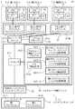
次に、本発明を実施するための最良の形態について図面を参照して詳細に説明する。図3は、本発明の第1実施形態のI/Oバスシステム10の構成を例示するブロック図である。本発明の第1実施形態のI/Oバスシステム10は、複数のホスト1と、PCIエクスプレススイッチ2と、I/Oリソース3とを含んでいる。複数のホスト1の各々は、CPU11と、ルートコンプレックス12と、メモリ13とを含んでいる。Next, the best mode for carrying out the present invention will be described in detail with reference to the drawings. FIG. 3 is a block diagram illustrating the configuration of an I/O bus system 10 according to a first embodiment of the present invention. The I/O bus system 10 according to the first embodiment of the present invention includes
図3を参照すると、そのI/Oリソース3は、複数のファンクション31(第1ファンクション31−1〜第Nファンクション31−N)を含み、ホスト1から同時に共有される。I/Oリソース3は、複数のホスト1の各々に、ファンクション31を個別に提供することで、複数のホスト1によるI/Oリソース3の同時共有を実現する。本実施形態では、第1ファンクション31−1〜第Nファンクション31−Nのそれぞれは、第1ホスト1−1〜第Nホスト1−Nに一対一で割り当てられている。ここで、複数のファンクション31を保持するI/Oリソース3としては、マルチファンクションI/Oや、単一ホスト内でのソフトウェア仮想化に対応したI/O(I/Oバーチャライゼーション対応のI/O)などが例示される。Referring to FIG. 3, the I/
PCIエクスプレススイッチ2は、ホスト1に接続する上流PCIエクスプレスネットワークブリッジ21と、ネットワークスイッチ22と、システムマネージャ23と、マルチルート接続ブリッジ24と、下流PCIエクスプレスネットワークブリッジ25とを含んでいる。マルチルート接続ブリッジ24は、下流PCIエクスプレスネットワークブリッジ25を複数の上流PCIエクスプレスネットワークブリッジ21と接続させることによって、I/Oリソース3を、複数のホスト1の間で同時に共有させる。The
特定の上流PCIエクスプレスネットワークブリッジ21は、他の上流PCIエクスプレスネットワークブリッジ21が存在せず、下流PCIエクスプレスネットワークブリッジ25と一対一で接続していることを想定して動作する。例えば、第1上流PCIエクスプレスネットワークブリッジ21−1は、第2上流PCIエクスプレスネットワークブリッジ21−2〜第N上流PCIエクスプレスネットワークブリッジ21−Nの挙動に依存することなく、独立に動作する。A specific upstream PCI
下流PCIエクスプレスネットワークブリッジ25は、設計上では、1つの上流PCIエクスプレスネットワークブリッジ21と接続することのみ可能である。そのため、本実施形態における下流PCIエクスプレスネットワークブリッジ25は、本来上流PCIエクスプレスネットワークブリッジ21と行う接続を、マルチルート接続ブリッジ24に対して行う。In terms of design, the downstream PCI
システムマネージャ23は、マルチルート接続ブリッジ24に制御パケットを送信し、下流PCIエクスプレスネットワークブリッジ25に接続される複数の上流PCIエクスプレスネットワークブリッジ21を制御し、I/Oリソース3の各ファンクション31を割り当てるホスト1を指定する。The
マルチルート接続ブリッジ24は、パケット転送部241と、I/O構成部242と、I/O情報記憶部243と、下流PCIエクスプレスネットワークブリッジ擬似レジスタ244と、I/Oファンクション擬似レジスタ245とを含んでいる。The multi-root connection bridge 24 includes a
パケット転送部241は、I/Oパケットがカプセル化されたネットワークパケットのネットワークパケットヘッダと、I/Oパケットヘッダをスワップして転送する。I/O構成部242は、I/Oリソース3のコンフィグレーションを行う。The
I/O情報記憶部243は、パケット転送部241がパケットに記載された情報をスワップする際に必要となる情報を保持する。下流PCIエクスプレスネットワークブリッジ擬似レジスタ244は、下流PCIエクスプレスネットワークブリッジ25の擬似レジスタ機能を提供する。I/Oファンクション擬似レジスタ245は、各ファンクション31の、擬似レジスタ機能を提供する。The I/O
本実施形態において、マルチルート接続ブリッジ24は、複数の下流PCIエクスプレスネットワークブリッジ擬似レジスタ244(第1下流PCIエクスプレスネットワークブリッジ擬似レジスタ244−1〜第N下流PCIエクスプレスネットワークブリッジ擬似レジスタ244−N)を含むものとする。また、マルチルート接続ブリッジ24は、複数のI/Oファンクション擬似レジスタ245(第1I/Oファンクション擬似レジスタ245−1〜第NI/Oファンクション擬似レジスタ245−N)を含むものとする。In this embodiment, the multi-root connection bridge 24 includes a plurality of downstream PCI Express network bridge pseudo registers 244 (first downstream PCI Express network bridge pseudo register 244-1 to N-th downstream PCI Express network bridge pseudo register 244-N). The multi-root connection bridge 24 also includes a plurality of I/O function pseudo registers 245 (first I/O function pseudo register 245-1 to N-th I/O function pseudo register 245-N).
第1下流PCIエクスプレスネットワークブリッジ擬似レジスタ244−1〜第N下流PCIエクスプレスネットワークブリッジ擬似レジスタ244−Nと第1I/Oファンクション擬似レジスタ245−1〜第NI/Oファンクション擬似レジスタ245−Nとは、それぞれ第1ホスト1−1〜第Nホスト1−Nからのアクセスを受け付ける。The first downstream PCI Express network bridge pseudo register 244-1 to the Nth downstream PCI Express network bridge pseudo register 244-N and the first I/O function pseudo register 245-1 to the Nth I/O function pseudo register 245-N respectively accept access from the first host 1-1 to the Nth host 1-N.
I/O構成部242は、I/Oリソース3がホスト1から使用される前に下流PCIエクスプレスネットワークブリッジ25とI/Oリソース3とのコンフィグレーションを行う。I/O構成部242は、ネットワークパケットにカプセル化したコンフィグレーションパケットを下流PCIエクスプレスネットワークブリッジ25と、I/Oリソース3に送信し、下流PCIエクスプレスネットワークブリッジ25とI/Oリソース3とのコンフィグレーションを行う。このときネットワークパケットのあて先は下流PCIエクスプレスネットワークブリッジ25に設定されている。また、I/O構成部242は、下流PCIエクスプレスネットワークブリッジ25とI/Oリソース3とのコンフィグレーション情報をI/O情報記憶部243に記録する。The I/
図4は、ホスト1とI/Oリソース3のアドレス空間の関連性を示す図である。I/Oリソース3のI/Oリソースアドレス空間32は、ID番号空間321と、物理メモリ空間322とを含んでいる。ID番号空間321は、「バス番号、デバイス番号、ファンクション番号」の群を含むID番号の空間である。Figure 4 is a diagram showing the relationship between the address spaces of the
図3に戻り、I/O構成部242は、I/Oリソース3のI/Oリソースアドレス空間32をコンフィグレーションする。ID番号空間321において、後でホスト1に割り当てるためのホスト1のホストマップ3211を、また物理メモリ空間322においてホスト1のホストマップ3221をコンフィグレーションする。ホスト1のホストマップ3211−1〜ホストマップ3211−Nとホスト1のホストマップ3221−1〜ホストマップ3221−Nとは、I/Oリソース3の第1ファンクション31−1〜第Nファンクション31−Nに対応する。Returning to FIG. 3, the I/
I/O構成部242は、また、ホスト1が下流PCIエクスプレスネットワークブリッジ25と、I/Oリソース3とに発行したコンフィグレーションパケットをパケット転送部241から受け取り、コンフィグレーションパケットがライトである場合、下流PCIエクスプレスネットワークブリッジ25へのコンフィグレーションは下流PCIエクスプレスネットワークブリッジ擬似レジスタ244に、I/Oリソース3へのコンフィグレーションはI/Oファンクション擬似レジスタ245に記録する。また、コンフィグレーションパケットがリードの場合、パケットが要求する情報を下流PCIエクスプレスネットワークブリッジ擬似レジスタ244か、I/Oファンクション擬似レジスタ245の該当する番地から読み込み、パケット転送部241を介してホスト1に返信する。The I/
I/O情報記憶部243は、I/O構成部242が行った下流PCIエクスプレスネットワークブリッジ25と、I/Oリソース3へのコンフィグレーション情報と、ホスト1が下流PCIエクスプレスネットワークブリッジ擬似レジスタ244と、I/Oファンクション擬似レジスタ245に書き込んだ情報を保持し、パケット転送部241がI/Oパケットがカプセル化されたネットワークパケットにおいて、ネットワークパケットとI/Oパケットのヘッダに記載された情報をスワップする際に必要となる情報を提供する。I/O情報記憶部243は、ターゲットホスト検索テーブル2431と、ホストマッピングテーブル2432とを保持する。The I/O
以下に、ターゲットホスト検索テーブル2431について説明を行う。図5Aは、ターゲットホスト検索テーブル2431の構成を例示するブロック図である。ターゲットホスト検索テーブル2431は、I/Oリソース3の各ファンクション31に対し、ファンクション31が割り当てられているホスト1とそのホスト1が接続する上流PCIエクスプレスネットワークブリッジ21のネットワークアドレス(HA)とを対応させる。第1ファンクション31−1〜第Nファンクション31−Nは、ファンクション番号FI1I〜FINIに対応する。 The target host search table 2431 will be described below. Fig. 5A is a block diagram illustrating an example of the configuration of the target host search table 2431. The target host search table 2431 associates each
以下に、ホストマッピングテーブル2432について説明を行う。図5Bは、ホストマッピングテーブル2432の構成を例示するブロック図である。ホストマッピングテーブル2432は、個別のホスト1毎に用意され、ホスト1が自身のルートコンプレックス12に与えたID番号と、ホスト1が割り当てられたI/Oリソース3のファンクション31に与えたID番号と、メモリ空間下限と上限とを、I/O構成部242がI/Oリソース3をコンフィグレーションした値に対応させる。ホストマッピングテーブル2432は、ID番号であるバス番号、デバイス番号、ファンクション番号をそれぞれB,D,Fで示している。図5Bは、ホストマッピングテーブル2432が保持するホスト1のホスト側アドレス空間14と、I/Oリソース3のI/Oリソースアドレス空間32のマッピング関係を示している。I/Oリソース3のI/Oリソースアドレス空間32において、ID番号空間321と物理メモリ空間322とが、ファンクション31を単位として、ホスト1のホスト側アドレス空間14のID番号空間141と物理メモリ空間142とにマッピングされている。The host mapping table 2432 will be described below. FIG. 5B is a block diagram illustrating the configuration of the host mapping table 2432. The host mapping table 2432 is prepared for each
図3に戻り、下流PCIエクスプレスネットワークブリッジ擬似レジスタ244は、ホスト1が下流PCIエクスプレスネットワークブリッジ25へコンフィグレーションライトで与える情報をホスト1毎に保持する。Returning to Figure 3, the downstream PCI Express network bridge
I/Oファンクション擬似レジスタ245は、ホスト1がI/Oリソース3のファンクション31へ与えるコンフィグレーション情報を保持する。また、ホスト1がファンクション31をコンフィグレーションする場合、ファンクション31に割り当てるメモリ空間の容量を質問するが、I/Oファンクション擬似レジスタ245がこの情報を提供する。この情報は、I/O構成部242がI/Oリソース3のコンフィグレーションを行う際、取得したI/Oリソース3に関する情報をI/O情報記録部243に記録するが、これをI/Oファンクション擬似レジスタ245に反映したものである。The I/O function
パケット転送部241は、ホスト1がI/Oリソース3に発行したコンフィグレーションパケット以外のI/Oパケットがカプセル化されたネットワークパケットをネットワークスイッチ22から受信し、ホスト1を表すネットワークパケットの送信元アドレスを、マルチルート接続ブリッジ24のネットワークアドレスにスワップする。また、送信元ホスト1に対応するホストマッピングテーブル2432を検索し、I/Oパケットの送信元アドレスをホスト1のホスト側アドレス空間14におけるルートコンプレックス12のID番号から、I/Oリソース3のI/Oリソースアドレス空間32におけるルートコンプレックス12のID番号にスワップする。The
また、I/Oバケットのあて先アドレスがID番号で表されている場合、I/Oパケットのあて先アドレスをホスト1のホスト側アドレス空間14におけるファンクション31のID番号から、I/Oリソース3のI/Oリソースアドレス空間32におけるファンクション31のID番号にスワップする。一方、I/Oパケットのあて先アドレスがメモリ空間で表されている場合、I/Oパケットのあて先アドレスを(あて先メモリ−Mem下限IxR+Mem下限IxI)にスワップする。ここでx=1〜Nで表される、I/Oパケットを送信したホスト1に対応する値である。Also, if the destination address of the I/O packet is represented by an ID number, the destination address of the I/O packet is swapped from the ID number of
パケット転送部241はまた、ホスト1が下流PCIエクスプレスネットワークブリッジ25とI/Oリソース3に送信したコンフィグレーションパケットをカプセル化したネットワークパケットをネットワークスイッチ22から受信し、コンフィグレーションパケットをデカプセル化し、I/O構成部242に渡す。パケット転送部241はまた、I/Oリソース3がホスト1に発行したI/Oパケットがカプセル化されたネットワークパケットを受信し、ネットワークパケットのあて先アドレスをマルチルート接続ブリッジ241のネットワークアドレスから、送信元ファンクション31が割り当てられたホスト1が接続する上流PCIエクスプレスネットワークブリッジ21のネットワークアドレスにスワップする。上流PCIエクスプレスネットワークブリッジ21のネットワークアドレスの検索は、I/O情報記憶部243が保持するターゲットホスト検索テーブル2431を用いて、I/Oパケットに記載された送信元ファンクション31をキーとして検索する。The
また、カプセル化されたI/Oパケットのあて先アドレスと送信元アドレスを、あて先ホスト1に対応するホストマッピングテーブル2432を参照してスワップする。スワップするアドレスの対応は、ホスト1がI/Oリソース3にI/Oパケットを送信する場合に行うスワップの参照と逆であり、I/Oリソース3のI/Oリソースアドレス空間32からホスト1のホスト側アドレス空間14にスワップする。パケット転送部241はまた、I/O構成部242からホスト1が下流PCIエクスプレスネットワークブリッジ擬似レジスタ244とI/Oファンクション擬似レジスタ245とに送信したコンフィグレーションパケットの応答を受信し、応答パケットのあて先ホスト1が接続する上流PCIエクスプレスネットワークブリッジ21のネットワークアドレスを用いて応答パケットをカプセル化し、ホスト1に送信する。パケット転送部241はまた、下流PCIエクスプレスネットワークブリッジ25が送信するブロードキャスト制御パケットを受信し、ブロードキャスト制御パケットをホスト1の数だけコピーし、それぞれのホストに送信する。このとき、下流PCIエクスプレスネットワークブリッジ25が送信したブロードキャスト制御パケットは、下流PCIエクスプレスネットワークブリッジ25の接続先として、マルチルート接続ブリッジ24の情報が記載されているが、パケット転送部241は、この接続先情報をホスト1がそれぞれ接続する上流PCIエクスプレス−ネットワークブリッジに書き換えてブロードキャスト制御パケットのコピーを送信する。The destination address and source address of the encapsulated I/O packet are swapped by referring to the host mapping table 2432 corresponding to the
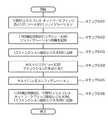
以下に、本発明を実施するための第1の実施の形態の動作について説明を行う。図6は、下流PCIエクスプレスネットワークブリッジ25とI/Oリソース3とをコンフィグレーションする際の動作を例示する図である。The operation of the first embodiment for implementing the present invention will be described below. Figure 6 is a diagram illustrating the operation when configuring the downstream PCI
I/O構成部242は、I/Oリソース3がホスト1から使用される前に、コンフィグレーションパケットを発行し、下流PCIエクスプレスネットワークブリッジ25と、I/Oリソース3とをコンフィグレーションする(ステップS401)。パケット転送部241は、I/O構成部242から渡されたコンフィグレーションパケットを、ネットワークパケットにカプセル化し、下流PCIエクスプレスネットワークブリッジ25との間でトンネリングすることにより、コンフィグレーションパケットを下流PCIエクスプレスネットワークブリッジ25とI/Oリソース3とに送信する。I/O構成部242は、I/Oリソース3に与えたコンフィグレーション情報を、I/O情報記憶部243が保持するホストマッピングテーブル2432に記録する(ステップS402)。I/O情報記憶部243に記録されたI/Oリソース3の各ファンクション31が要求するメモリ空間の容量は、I/Oファンクション擬似レジスタ245に反映される(ステップS403)。Before the I/
次に、システムマネージャ23は、マルチルート接続ブリッジ24に制御パケットを発行し、I/Oリソース3の第1ファンクション31−1〜第Nファンクション31−Nを、それぞれ第1ホスト1−1〜第Nホスト1−Nに割り当てる(ステップS404)。この割り当てにより、I/O情報記憶部243が保持するターゲットホスト検索テーブル2431のホストに関するエントリが記載される。Next, the
次に、各ホスト1はそれぞれのコンフィグレーションサイクルを開始する(ステップS405)。ホスト1が下流PCIエクスプレスネットワークブリッジ25に発行するコンフィグレーションパケットは、ホスト1に割り当てられた下流PCIエクスプレスネットワークブリッジ擬似レジスタ244に、またホスト1に割り当てられたI/Oリソース3が含むファンクション31に発行するコンフィグレーションパケットは、ファンクション31に対応するI/Oファンクション擬似レジスタ245へのアクセスとしてI/O構成部242が処理する。また、I/O情報記憶部243のホストマッピングテーブル2432のエントリを記載するために必要な情報が、ホストのコンフィグレーションアクセスから抽出され、エントリが形成される(ステップS406)。Next, each
図7は、ホスト1がI/Oリソース3にコンフィグレーションパケット以外のI/Oパケットを送信する際の動作を例示する図である。ルートコンプレックス12は、CPU11上で動作するソフトウェアの命令により、ホスト1に割り当てられたI/Oリソース3のファンクション31に対しI/Oパケットを送信する(ステップS501)。上流PCIエクスプレスネットワークブリッジ21は、ルートコンプレックス12が発行したI/Oパケットを受信し、I/Oリソース3が接続する下流PCIエクスプレスネットワークブリッジ25のネットワークアドレスを用いてI/Oパケットをカプセル化し、ネットワークスイッチ22に送信する(ステップS502)。ネットワークスイッチ22は、I/Oパケットがカプセル化されたネットワークパケットをマルチルート接続ブリッジ24に転送する(ステップS503)。7 is a diagram illustrating the operation when the
パケット転送部241は、I/Oパケットがカプセル化されたネットワークパケットを受信し、ホスト1を表すネットワークパケットの送信元アドレスを、マルチルート接続ブリッジ24のネットワークアドレスにスワップする(ステップS504)。また、送信ホストに対応するホストマッピングテーブル2432を検索し、I/Oパケットの送信元アドレスをホスト1のホスト側アドレス空間14におけるルートコンプレックス12のID番号から、I/Oリソース3のI/Oリソースアドレス空間32におけるルートコンプレックス12のID番号にスワップする。また、I/Oバケットのあて先アドレスがID番号で表されている場合、I/Oパケットのあて先アドレスをホスト1のアドレス空間におけるファンクション31のID番号から、I/Oリソース3のI/Oリソースアドレス空間32におけるファンクション31のID番号にスワップする。一方、I/Oパケットのあて先アドレスがメモリ空間で表されている場合、I/Oパケットのあて先アドレスを(あて先メモリ−Mem下限IxR+Mem下限IxI)にスワップする。ここでx=1〜Nで表される、I/Oパケットを送信したホスト1に対応する値である。次にパケット転送部241は、ネットワークパケットを下流PCIエクスプレスネットワークブリッジ25に送信する。The
下流PCIエクスプレスネットワークブリッジ25は、I/Oパケットをデカプセル化し(ステップS505)、I/Oリソース3に送信する。I/Oリソース3のファンクション31は、ファンクション31が割り当てられたホスト1が送信したI/Oパケットを受信する(ステップS506)。The downstream PCI
図8は、I/Oリソース3からホスト1にI/Oパケットを送信する際の動作を例示する図である。I/Oリソース3のファンクション31は、割り当てられたホストにI/Oパケットを送信する(ステップS601)。下流PCIエクスプレスネットワークブリッジ25は、ファンクション31が発行したI/Oパケットを受信し、マルチルート接続ブリッジ24のネットワークアドレスをあて先アドレスとしてI/Oパケットをカプセル化し、マルチルート接続ブリッジ24に送信する(ステップS602)。Figure 8 is a diagram illustrating the operation when an I/O packet is sent from the I/
パケット転送部241は、I/Oパケットがカプセル化されたネットワークパケットを受信し、マルチルート接続ブリッジ24を表すネットワークパケットのあて先アドレスを、I/Oパケットのあて先となるホスト1のネットワークアドレスにスワップする(ステップS603)。あて先となるホスト1のネットワークアドレスは、ターゲットホスト検索テーブル2431において、ネットワークパケットにカプセル化されたI/Oパケットに記載された送信元ファンクション番号をキーとして検索する。また、あて先ホストに対応するホストマッピングテーブル2432を検索し、I/Oパケットの送信元アドレスをI/Oリソース3のI/Oリソースアドレス空間32におけるファンクション31のID番号から、ホスト1のホスト側アドレス空間14におけるファンクション31のID番号にスワップする。また、I/Oバケットのあて先アドレスがID番号で表されている場合、I/Oパケットのあて先アドレスをI/Oリソース3のI/Oリソースアドレス空間32におけるルートコンプレックス12のID番号から、ホスト1のホスト側アドレス空間14におけるルートコンプレックス12のID番号にスワップする。一方、I/Oパケットのあて先アドレスがメモリ空間で表されている場合、I/Oパケットのあて先アドレスを(あて先メモリ−Mem下限IxI+Mem下限IxR)にスワップする。ここでx=1〜Nで表される、I/Oパケットのあて先ホスト1に対応する値である。次に、パケット転送部241はネットワークパケットをネットワークスイッチ22に送信する。The
ネットワークスイッチ22は、I/Oパケットがカプセル化されたネットワークパケットを上流PCIエクスプレスネットワークブリッジ21に転送する(ステップS604)。The network switch 22 forwards the network packet in which the I/O packet is encapsulated to the upstream PCI Express network bridge 21 (step S604).
上流PCIエクスプレスネットワークブリッジ21は、I/Oパケットをデカプセル化し(ステップS605)、ルートコンプレックス12に送信する。ルートコンプレックス12は、ホスト1に割り当てられたファンクション31が発行したI/Oパケットを受信する(ステップS606)。The upstream PCI
ここで本実施の形態では、ネットワークスイッチ22が1つの場合を示したが、上流PCIエクスプレスネットワークブリッジ21とマルチルート接続ブリッジ24との間に接続するネットワークスイッチ22の数に制限はない。また、マルチルート接続ブリッジ24と下流PCIエクスプレスネットワークブリッジ25との間に別のネットワークスイッチ22を接続しても良い。Here, in this embodiment, the case where there is one
また、本実施の形態ではI/Oリソース3が1つの場合を示したが、複数のホスト1から同時に共有されるI/Oリソース3の数に制限はない。ネットワークスイッチ22を用いて複数のI/Oリソース3を接続しても良い。Although the present embodiment shows a case where there is one I/
また、本実施の形態では、I/Oリソースの第1ファンクション31−1〜第Nファンクション31−Nをそれぞれ第1ホスト1−1〜第Nホスト1−Nに割り当てる場合を示したが、ファンクション31のホスト1への割り当て方の組み合わせは自由である。また、複数のファンクション31が割り当てられるホスト1や、ファンクション31が割り当てられないホスト1が存在しても良い。I/Oリソース3が保持するファンクション31の数とホスト1の数は異なっていても良い。Although this embodiment shows a case where the first function 31-1 to the Nth function 31-N of the I/O resource are assigned to the first host 1-1 to the Nth host 1-N, the combination of how the
上述したように、第1の実施の形態では、マルチルート接続ブリッジが本来1つの上流PCIエクスプレス−ネットワークブリッジと接続する下流PCIエクスプレスネットワークブリッジを、複数の上流PCIエクスプレス−ネットワークブリッジに接続させ、I/Oリソースの機能を、ファンクションを単位として各ホストに割り当てる。As described above, in the first embodiment, the multi-root connection bridge connects a downstream PCI Express network bridge that is normally connected to one upstream PCI Express network bridge to multiple upstream PCI Express network bridges, and assigns I/O resource functions to each host on a function basis.
このため、マルチルート接続ブリッジは、各ホストが送信するネットワークパケットは全てマルチルート接続ブリッジから送られているよう擬似し、また下流PCIエクスプレス−ネットワークブリッジが送信したネットワークパケットのあて先アドレスをマルチルート接続ブリッジから各ホストのネットワークアドレスにスワップする。一方、マルチルート接続ブリッジは、I/Oリソースを予めコンフィグレーションし、そのコンフィグレーション情報を各ホストがI/Oリソースに与えるコンフィグレーションに対してマップする。そして、ホストとI/O間で送受信されるI/Oパケットのヘッダに記載されている情報を、マッピング情報を用いてスワップする。これにより、I/O機能を、ファンクションを単位として各ホストに割り当て、複数ホストからI/Oリソースを同時に共有できる。For this reason, the multi-root connection bridge simulates that all network packets sent by each host are sent from the multi-root connection bridge, and swaps the destination address of network packets sent by the downstream PCI Express-network bridge from the multi-root connection bridge to the network address of each host. Meanwhile, the multi-root connection bridge configures I/O resources in advance, and maps that configuration information to the configuration that each host gives to the I/O resources. Then, it swaps the information written in the header of I/O packets sent and received between the host and I/O using the mapping information. This allows I/O functions to be assigned to each host in function units, and I/O resources to be shared simultaneously by multiple hosts.
次に、本発明を実施するための第2の実施の形態について、図面を参照して説明する。図9は、本発明の第2の実施の形態の構成を示すブロック図である。図9を参照すると、本発明の第2の実施の形態に係るI/Oバスシステム10は、図3に示した第1の実施の形態におけるPCIエクスプレススイッチ2が、マルチルート接続ブリッジ41を含む点で異なっている。Next, a second embodiment for carrying out the present invention will be described with reference to the drawings. FIG. 9 is a block diagram showing the configuration of the second embodiment of the present invention. Referring to FIG. 9, the I/O bus system 10 according to the second embodiment of the present invention differs from the first embodiment shown in FIG. 3 in that the
第2実施形態におけるマルチルート接続ブリッジ41は、I/Oパケットがカプセル化されたネットワークパケットの処理を行うプロセッサ411と、パケット処理のプログラムとI/Oバスシステム10のコンフィグレーション情報を保持するメモリ412とを含む。The multi-root connection bridge 41 in the second embodiment includes a
メモリ412は、第1の実施の形態におけるパケット転送部241と、I/O構成部242との機能をプロセッサ411に行わせるマルチルート接続ブリッジプログラム4121と、I/O情報記憶部243と同じ情報を保持するI/O情報記憶部4122と、下流PCIエクスプレスネットワークブリッジ擬似レジスタ244と同じ情報を保持する下流PCIエクスプレス−ネットワークブリッジレジスタ情報記憶部4123と、I/Oファンクション擬似レジスタ245と同じ情報を保持するI/Oファンクションレジスタ情報記憶部4124とを含む。The memory 412 includes a multi-root
マルチルート接続ブリッジプログラム4121は、プロセッサ411に読み込まれ、プロセッサ411に、第1の実施の形態におけるパケット転送部241と、I/O構成部242との機能を行わせる。その際、第1の実施の形態において発生したI/O情報記憶部243と、下流PCIエクスプレスネットワークブリッジ擬似レジスタ244と、I/Oファンクション擬似レジスタ245に対するアクセスは、メモリ412が保持するI/O情報記憶部4122と、下流PCIエクスプレス−ネットワークブリッジレジスタ情報記憶部4123と、I/Oファンクションレジスタ情報記憶部4124とにおいて対応する番地に対して発生する。The multi-root
本発明の第2の実施の形態では、メモリが保持するプログラムを用いてプロセッサに第1の実施の形態におけるマルチルート接続ブリッジと同じ機能を行わせる。よって、特別なハードウェアを開発せず、設計したプログラムを汎用プロセッサで動作させることにより、複数ホストからのI/O同時共有を実現できる。In the second embodiment of the present invention, a program stored in memory is used to cause a processor to perform the same functions as the multi-root connection bridge in the first embodiment. Therefore, it is possible to realize simultaneous sharing of I/O from multiple hosts by running a designed program on a general-purpose processor without developing special hardware.
以上、本願発明の実施の形態を具体的に説明した。本願発明は上述の実施の形態に限定されるものではなく、その要旨を逸脱しない範囲で種々変更可能である。また、本発明は、コンピュータ装置やネットワーク装置、産業用機器やコンシューマ機器において、複数のコンピュータ、あるいはCPUやCPUに類する演算装置を含む情報処理装置の間で、I/Oデバイスを共有するといった用途に適用できる。The above describes the specific embodiments of the present invention. The present invention is not limited to the above-mentioned embodiments, and various modifications are possible without departing from the spirit of the invention. The present invention can also be applied to applications such as sharing an I/O device between multiple computers, or information processing devices including a CPU or a CPU-like arithmetic unit, in computer equipment, network equipment, industrial equipment, and consumer equipment.
上述してきたI/Oバスシステムは、ネットワークパケットに記載されたネットワークアドレスをスワップし、単一の下流PCIエクスプレス−ネットワークブリッジと複数の上流PCIエクスプレス−ネットワークブリッジとを接続することを特徴とする。The I/O bus system described above is characterized by swapping network addresses contained in network packets and connecting a single downstream PCI Express-network bridge to multiple upstream PCI Express-network bridges.
換言すると、上述してきたI/Oバスシステムは、上流PCIエクスプレス−ネットワークブリッジが送信したネットワークパケットの送信元アドレスを、接続を仲介するブリッジのネットワークアドレスにスワップして下流PCIエクスプレス−ネットワークブリッジに送信し、その下流PCIエクスプレス−ネットワークブリッジが送信したネットワークパケットの送信先アドレスを、接続を仲介するブリッジのネットワークアドレスからその上流PCIエクスプレス−ネットワークブリッジのネットワークアドレスにスワップしてその上流PCIエクスプレス−ネットワークブリッジに送信することを特徴とする。In other words, the I/O bus system described above is characterized in that the source address of a network packet sent by the upstream PCI Express-network bridge is swapped to the network address of the bridge mediating the connection and sent to the downstream PCI Express-network bridge, and the destination address of a network packet sent by the downstream PCI Express-network bridge is swapped from the network address of the bridge mediating the connection to the network address of the upstream PCI Express-network bridge and sent to the upstream PCI Express-network bridge.
また、上述してきたI/Oバスシステムは、I/Oリソースをあらかじめコンフィグレーションし、ホストが行うコンフィグレーションに対しI/Oリソースを、ファンクションを単位としてマッピングすることを特徴とする。The I/O bus system described above is also characterized by the fact that I/O resources are configured in advance and the I/O resources are mapped to the configuration performed by the host on a function basis.
なお、そのI/Oバスシステムは、I/Oリソースをあらかじめコンフィグレーションし、ホストがI/Oリソースに与えるコンフィグレーション情報を記憶し、I/Oリソースのコンフィグレーション情報とそのホストがI/Oリソースに与えるコンフィグレーション情報のマッピング情報を記憶し、その記憶したマッピング情報を参照し、ホストとI/Oリソースの間で送受信するI/Oパケットのヘッダに記載されたアドレスをスワップすることを特徴とする。The I/O bus system is characterized by pre-configuring I/O resources, storing configuration information that the host provides to the I/O resources, storing mapping information between the I/O resource configuration information and the configuration information that the host provides to the I/O resources, and by referring to the stored mapping information, swapping the addresses written in the headers of I/O packets sent and received between the host and the I/O resources.
また、上述のI/Oバスシステムを動作させるための手順を示すI/Oバスシステム制御プログラムを、所定の記録媒体に記憶させることも可能である。その場合、I/Oバスシステム制御プログラムを記憶するI/Oバスシステム制御プログラム記録媒体は、複数の上流PCIエクスプレス−ネットワークブリッジと複数のホストとを一対一に接続するステップと、単一の下流PCIエクスプレス−ネットワークブリッジとI/Oリソースとを接続するステップと、その上流PCIエクスプレス−ネットワークブリッジとその下流PCIエクスプレス−ネットワークブリッジとの間で、その複数のホストとそのI/Oリソースとの間を伝送するネットワークパケットに記載されたネットワークアドレスをスワップするステップとを具備する動作を実現するための手順を示すI/Oバスシステム制御プログラムを記憶する。It is also possible to store an I/O bus system control program showing the procedure for operating the above-mentioned I/O bus system in a specified recording medium. In this case, the I/O bus system control program recording medium storing the I/O bus system control program stores an I/O bus system control program showing the procedure for realizing an operation including a step of connecting multiple upstream PCI Express-network bridges to multiple hosts one-to-one, a step of connecting a single downstream PCI Express-network bridge to an I/O resource, and a step of swapping network addresses written in network packets transmitted between the multiple hosts and their I/O resources between the upstream PCI Express-network bridge and the downstream PCI Express-network bridge.
そのI/Oバスシステム制御プログラム記録媒体は、そのスワップするステップが、上流PCIエクスプレス−ネットワークブリッジが送信したネットワークパケットの送信元アドレスを、接続を仲介するブリッジのネットワークアドレスにスワップして下流PCIエクスプレス−ネットワークブリッジに送信するステップと、その下流PCIエクスプレス−ネットワークブリッジが送信したネットワークパケットの送信先アドレスを、接続を仲介するブリッジのネットワークアドレスからその上流PCIエクスプレス−ネットワークブリッジのネットワークアドレスにスワップしてその上流PCIエクスプレス−ネットワークブリッジに送信するステップを含むことを特徴とするI/Oバスシステム制御プログラムを記憶する。The I/O bus system control program recording medium stores an I/O bus system control program characterized in that the swapping step includes a step of swapping the source address of a network packet sent by the upstream PCI Express-network bridge with the network address of a bridge mediating the connection and sending the packet to the downstream PCI Express-network bridge, and a step of swapping the destination address of the network packet sent by the downstream PCI Express-network bridge from the network address of the bridge mediating the connection with the network address of the upstream PCI Express-network bridge and sending the packet to the upstream PCI Express-network bridge.
そのI/Oバスシステム制御プログラム記録媒体は、さらに、I/Oリソースをあらかじめコンフィグレーションし、ホストが行うコンフィグレーションに対し、そのI/Oリソースを、ファンクションを単位としてマッピングするステップを具備する動作を実現するための手順を示すI/Oバスシステム制御プログラムを記憶する。The I/O bus system control program recording medium further stores an I/O bus system control program that indicates procedures for realizing operations that include steps for pre-configuring I/O resources and mapping the I/O resources on a function-by-function basis to the configuration performed by the host.
そのI/Oバスシステム制御プログラム記録媒体は、そのマッピングするステップが、 I/Oリソースをあらかじめコンフィグレーションするステップと、ホストがI/Oリソースに与えるコンフィグレーション情報を記憶するステップと、I/Oリソースのコンフィグレーション情報とそのホストがI/Oリソースに与えるコンフィグレーション情報のマッピング情報を記憶するステップとを備え、そのスワップするステップが、その記憶したマッピング情報を参照し、ホストとI/Oリソースの間で送受信するI/Oパケットのヘッダに記載されたアドレスをスワップするステップを含むI/Oバスシステム制御プログラムを記憶する。The I/O bus system control program recording medium stores an I/O bus system control program in which the mapping step includes a step of configuring I/O resources in advance, a step of storing configuration information that the host provides to the I/O resources, and a step of storing mapping information between the I/O resource configuration information and the configuration information that the host provides to the I/O resources, and the swapping step includes a step of referring to the stored mapping information and swapping addresses written in the headers of I/O packets transmitted and received between the host and the I/O resources.
そのI/Oバスシステム制御プログラム記録媒体は、I/Oリソースのファンクションが割り当てられたホストを記憶するステップを具備する動作を実現するための手順を示すI/Oバスシステム制御プログラムを記憶する。ここにおいて、そのI/Oバスシステム制御プログラム記録媒体は、そのコンフィグレーションするステップが、I/Oリソースと下流PCIエクスプレス−ネットワークブリッジをあらかじめコンフィグレーションし、そのスワップするステップが、その記憶したI/Oリソースのファンクションが割り当てられたホストに関する情報を参照してI/Oパケットをカプセル化したネットワークパケットのネットワークアドレスをスワップし、その記憶したコンフィグレーション情報のマッピング情報を参照してネットワークパケットにカプセル化されたI/Oパケットのアドレスをスワップするステップを含むことを特徴とするI/Oバスシステム制御プログラムを記憶する。The I/O bus system control program recording medium stores an I/O bus system control program showing a procedure for realizing an operation including a step of storing a host to which an I/O resource function is assigned. The I/O bus system control program recording medium stores an I/O bus system control program characterized in that the configuring step pre-configures an I/O resource and a downstream PCI Express-network bridge, and the swapping step includes a step of swapping the network address of a network packet encapsulating an I/O packet by referring to information about a host to which the stored I/O resource function is assigned, and swapping the address of an I/O packet encapsulated in a network packet by referring to mapping information in the stored configuration information.
そのI/Oバスシステム制御プログラム記録媒体は、そのネットワークアドレスのスワップが、上流PCIエクスプレス−ネットワークブリッジが送信したネットワークパケットの送信元アドレスを、接続を仲介するブリッジのネットワークアドレスにスワップし、その下流PCIエクスプレス−ネットワークブリッジが送信したネットワークパケットの送信先アドレスを、その接続を仲介するブリッジのネットワークアドレスからその上流PCIエクスプレス−ネットワークブリッジのネットワークアドレスにスワップすることを特徴とするI/Oバスシステム制御プログラムを記憶する。The I/O bus system control program recording medium stores an I/O bus system control program characterized in that the network address swapping involves swapping the source address of a network packet sent by an upstream PCI Express-network bridge to the network address of a bridge mediating the connection, and swapping the destination address of a network packet sent by the downstream PCI Express-network bridge from the network address of the bridge mediating the connection to the network address of the upstream PCI Express-network bridge.
そのI/Oバスシステム制御プログラム記録媒体は、ホストに割り当てるI/Oリソースのファンクションを、制御パケットにより変更する処理をプロセッサに行わせるステップを具備する動作を実現するための手順を示すI/Oバスシステム制御プログラムを記憶する。The I/O bus system control program recording medium stores an I/O bus system control program indicating procedures for realizing operations including a step of causing a processor to perform processing to change the function of an I/O resource to be assigned to a host using a control packet.
そのI/Oバスシステム制御プログラム記録媒体は、そのI/Oパケットのアドレスのスワップが、I/Oパケットに記載されたメモリ空間とID番号を対象とすることを特徴とするI/Oバスシステム制御プログラムを記憶する。The I/O bus system control program recording medium stores an I/O bus system control program characterized in that the swapping of addresses of the I/O packets targets the memory space and ID number written in the I/O packets.
当業者は上記実施例の様々な変形を容易に実施することができる。したがって、本発明は上記実施例に限定されることはなく、請求項やその均等物によって参酌される最も広い範囲で解釈される。
この出願は、2008年11月13日に出願された日本出願特願2008−290692を基礎とする優先権を主張し、その開示の全てをここに取り込む。 Those skilled in the art can easily implement various modifications of the above-mentioned embodiments, therefore, the present invention is not limited to the above-mentioned embodiments, but is to be interpreted in the broadest scope as defined by the claims and their equivalents.
This application claims priority based on Japanese Patent Application No. 2008-290692, filed November 13, 2008, the disclosure of which is incorporated herein by reference in its entirety.
Claims (10)
Translated fromJapaneseI/Oリソースに接続される単一の下流PCIエクスプレス−ネットワークブリッジと、
前記上流PCIエクスプレス−ネットワークブリッジと前記下流PCIエクスプレス−ネットワークブリッジとの間に配置され、前記複数のホストと前記I/Oリソースとの間を伝送するネットワークパケットに記載されたネットワークアドレスをスワップする接続ブリッジと
を具備し、
前記接続ブリッジは、
前記上流PCIエクスプレス−ネットワークブリッジが送信したネットワークパケットの送信元アドレスを、接続を仲介するブリッジのネットワークアドレスにスワップして下流PCIエクスプレス−ネットワークブリッジに送信し、
前記下流PCIエクスプレス−ネットワークブリッジが送信したネットワークパケットの送信先アドレスを、前記接続を仲介するブリッジのネットワークアドレスから前記上流PCIエクスプレス−ネットワークブリッジにスワップして前記上流PCIエクスプレス−ネットワークブリッジに送信する
I/Oバスシステム。 a plurality of upstream PCI Express-network bridges connected one-to-one to a plurality of hosts;
a single downstream PCI Express to network bridge connected to I/O resources;
a connection bridge disposed between the upstream PCI Express-network bridge and the downstream PCI Express-network bridge, for swapping network addresses written in network packets transmitted between the multiple hosts and the I/O resources;
The connecting bridge is
swapping a source address of a network packet transmitted by the upstream PCI Express-network bridge into a network address of a bridge that mediates the connection and transmitting the packet to the downstream PCI Express-network bridge;
an I/O bus system which swaps a destination address of a network packet transmitted by the downstream PCI Express-network bridge from a network address of a bridge mediating the connection to the upstream PCI Express-network bridge and transmits the packet to the upstream PCI Express-network bridge.
前記接続ブリッジは、
前記I/Oリソースを、あらかじめコンフィグレーションし、前記ホストが行うコンフィグレーションに対し前記I/Oリソースを、ファンクションを単位としてマッピングすることを特徴とする
I/Oバスシステム。2. The I/O bus system according toclaim 1 ,
The connecting bridge is
An I/O bus system, comprising: a first I/O resource configured in advance; and a second I/O resource mapped to the configuration performed by the host in units of functions.
前記接続ブリッジは、
前記I/Oリソースをあらかじめコンフィグレーションするコンフィグレーション手段と、
前記ホストが前記I/Oリソースに与えるコンフィグレーション情報を記憶するコンフィグレーション情報記憶手段と、
前記I/Oリソースのコンフィグレーション情報と、前記ホストが前記I/Oリソースに与えるコンフィグレーション情報とのマッピング情報を記憶するマッピング情報記憶手段と、
前記マッピング情報を参照して前記ホストと前記I/Oリソースの間で送受信するI/Oパケットのヘッダに記載されたアドレスをスワップするスワップ手段と
を備えたことを特徴とする
I/Oバスシステム。3. The I/O bus system according toclaim 2 ,
The connecting bridge is
a configuration means for pre-configuring the I/O resources;
a configuration information storage means for storing configuration information that the host provides to the I/O resource;
a mapping information storage means for storing mapping information between configuration information of the I/O resources and configuration information provided by the host to the I/O resources;
a swapping unit which refers to the mapping information and swaps addresses written in headers of I/O packets transmitted and received between the host and the I/O resource.
前記I/Oリソースのファンクションが割り当てられたホストを記憶するファンクション割り当て記憶手段を備え、
前記上流PCIエクスプレス−ネットワークブリッジは、前記ホストをネットワークに接続し、
前記下流PCIエクスプレス−ネットワークブリッジは、前記I/Oリソースをネットワークに接続し、
前記コンフィグレーション手段は、前記I/Oリソースと前記下流PCIエクスプレス−ネットワークブリッジとをあらかじめコンフィグレーションし、
前記スワップ手段は、
前記ファンクション割り当て記憶手段を参照してI/Oパケットをカプセル化したネットワークパケットのネットワークアドレスをスワップし、
前記I/Oリソースのコンフィグレーション情報と、前記ホストが前記I/Oリソースに与えるコンフィグレーション情報とのマッピング情報を参照してネットワークパケットにカプセル化されたI/Oパケットのアドレスをスワップすることを特徴とする
I/Oバスシステム。4. The I/O bus system according toclaim 3 , further comprising:
a function allocation storage means for storing a host to which a function of the I/O resource is allocated,
the upstream PCI Express-to-network bridge connects the host to a network;
the downstream PCI Express-to-network bridge connects the I/O resources to a network;
The configuration means pre-configures the I/O resources and the downstream PCI Express-network bridge;
The swapping means includes:
swapping the network addresses of the network packets encapsulating the I/O packets by referring to the function allocation storage means;
and swapping addresses of I/O packets encapsulated in network packets by referring to mapping information between configuration information of the I/O resource and configuration information provided by the host to the I/O resource.
前記スワップ手段は、
前記上流PCIエクスプレス−ネットワークブリッジが送信したネットワークパケットの送信元アドレスを、前記スワップ手段のネットワークアドレスにスワップし、
前記下流PCIエクスプレス−ネットワークブリッジが送信したネットワークパケットの送信先アドレスを、前記スワップ手段のネットワークアドレスから前記上流PCIエクスプレス−ネットワークブリッジのネットワークアドレスにスワップすることを特徴とする
I/Oバスシステム。5. The I/O bus system according toclaim 4 ,
The swapping means includes:
Swapping a source address of a network packet transmitted by the upstream PCI Express-network bridge to a network address of the swapping means;
an I/O bus system, characterized in that a destination address of a network packet transmitted by said downstream PCI Express-network bridge is swapped from a network address of said swapping means to a network address of said upstream PCI Express-network bridge.
前記ホストに割り当てる前記I/Oリソースのファンクションは、制御パケットにより変更できることを特徴とする
I/Oバスシステム。6. The I/O bus system according toclaim 5 ,
An I/O bus system, characterized in that a function of the I/O resource assigned to the host can be changed by a control packet.
前記I/Oパケットのアドレスのスワップは、前記I/Oパケットに記載されたメモリ空間とID番号とを対象とすることを特徴とする
I/Oバスシステム。7. The I/O bus system according toclaim 6 ,
2. An I/O bus system according to claim 1, wherein the swapping of the addresses of the I/O packets is performed for memory spaces and ID numbers written in the I/O packets.
I/Oリソースを下流PCIエクスプレス−ネットワークブリッジを用いてネットワークに接続し、
I/Oリソースと前記下流PCIエクスプレス−ネットワークブリッジをあらかじめコンフィグレーションし、
ホストがI/Oリソースに与えるコンフィグレーション情報を記憶し、
I/Oリソースのファンクションが割り当てられたホストを記憶し、
I/Oリソースのコンフィグレーション情報と前記ホストがI/Oリソースに与えるコンフィグレーション情報のマッピング情報を記憶し、
前記記憶したI/Oリソースのファンクションが割り当てられたホストに関する情報を参照してI/Oパケットをカプセル化したネットワークパケットのネットワークアドレスをスワップし、前記記憶したコンフィグレーション情報のマッピング情報を参照してネットワークパケットにカプセル化されたI/Oパケットのアドレスをスワップし、
前記ネットワークアドレスのスワップは、前記上流PCIエクスプレス−ネットワークブリッジが送信したネットワークパケットの送信元アドレスを、接続を仲介するブリッジのネットワークアドレスにスワップし、前記下流PCIエクスプレス−ネットワークブリッジが送信したネットワークパケットの送信先アドレスを、前記接続を仲介するブリッジのネットワークアドレスから前記上流PCIエクスプレス−ネットワークブリッジのネットワークアドレスにスワップすることを特徴とする
I/Oバスシステム制御方法。 Connecting the host to the network using an upstream PCI Express to network bridge;
connecting the I/O resources to a network using a downstream PCI Express-to-network bridge;
pre-configuring I/O resources and the downstream PCI Express-to-network bridge;
storing configuration information that the host provides to the I/O resources;
Remembering the host to which the I/O resource function is assigned;
storing mapping information between configuration information of I/O resources and configuration information provided by the host to the I/O resources;
swapping network addresses of network packets encapsulating I/O packets by referring to information about a host to which a function of the stored I/O resource is assigned, andswapping addresses of the I/O packets encapsulated in network packets by referring to mapping information in the stored configuration information;
said swapping of network addresses comprises swapping a source address of a network packet transmitted by said upstream PCI Express-network bridge to a network address of a bridge that mediates the connection, and swapping a destination address of a network packet transmitted by said downstream PCI Express-network bridge from the network address of the bridge that mediates the connection to the network address of said upstream PCI Express-network bridge.
ホストに割り当てるI/Oリソースのファンクションを、制御パケットにより変更することを特徴とする
I/Oバスシステム制御方法。9. The I/O bus system control method according toclaim 8 ,
An I/O bus system control method, comprising the steps of: changing a function of an I/O resource assigned to a host by a control packet.
前記I/Oパケットのアドレスのスワップは、I/Oパケットに記載されたメモリとID番号を対象とすることを特徴とする
I/Oバスシステム制御方法。10. The I/O bus system control method according toclaim 9 ,
2. The I/O bus system control method, wherein the swapping of the addresses of the I/O packets is performed on the memory and ID number written in the I/O packets.
Priority Applications (1)
| Application Number | Priority Date | Filing Date | Title |
|---|---|---|---|
| JP2010537754AJP5434929B2 (en) | 2008-11-13 | 2009-11-04 | I/O Bus System |
Applications Claiming Priority (4)
| Application Number | Priority Date | Filing Date | Title |
|---|---|---|---|
| JP2008290692 | 2008-11-13 | ||
| JP2008290692 | 2008-11-13 | ||
| PCT/JP2009/068789WO2010055791A1 (en) | 2008-11-13 | 2009-11-04 | I/o bus system |
| JP2010537754AJP5434929B2 (en) | 2008-11-13 | 2009-11-04 | I/O Bus System |
Publications (2)
| Publication Number | Publication Date |
|---|---|
| JPWO2010055791A1 JPWO2010055791A1 (en) | 2012-04-12 |
| JP5434929B2true JP5434929B2 (en) | 2014-03-05 |
Family
ID=42169926
Family Applications (1)
| Application Number | Title | Priority Date | Filing Date |
|---|---|---|---|
| JP2010537754AActiveJP5434929B2 (en) | 2008-11-13 | 2009-11-04 | I/O Bus System |
Country Status (3)
| Country | Link |
|---|---|
| US (1) | US9213662B2 (en) |
| JP (1) | JP5434929B2 (en) |
| WO (1) | WO2010055791A1 (en) |
Families Citing this family (12)
| Publication number | Priority date | Publication date | Assignee | Title |
|---|---|---|---|---|
| JP5467541B2 (en)* | 2010-02-22 | 2014-04-09 | 日本電気株式会社 | Communication control system, switching node, communication control method, and communication control program |
| JP5598148B2 (en)* | 2010-08-05 | 2014-10-01 | 富士通株式会社 | Switching apparatus, information processing apparatus, and switching apparatus control method |
| CN102694712B (en)* | 2011-06-27 | 2014-11-26 | 威盛电子股份有限公司 | Network system and network-to-network bridge |
| JP5903801B2 (en)* | 2011-08-23 | 2016-04-13 | 富士通株式会社 | Communication apparatus and ID setting method |
| US8832331B2 (en) | 2011-08-29 | 2014-09-09 | Ati Technologies Ulc | Data modification for device communication channel packets |
| US9032102B2 (en)* | 2012-03-02 | 2015-05-12 | International Business Machines Corporation | Decode data for fast PCI express multi-function device address decode |
| JP2013196593A (en)* | 2012-03-22 | 2013-09-30 | Ricoh Co Ltd | Data processing apparatus, data processing method and program |
| JP2014002545A (en)* | 2012-06-18 | 2014-01-09 | Ricoh Co Ltd | Data transfer device, and data transfer method |
| US8891542B2 (en) | 2012-12-19 | 2014-11-18 | International Business Machines Corporation | Unified system networking with CEE-PCIe tunneling |
| US8917736B2 (en) | 2012-12-19 | 2014-12-23 | International Business Machines Corporation | Unified system networking with PCIE-CEE tunneling |
| JPWO2017154942A1 (en)* | 2016-03-11 | 2019-01-17 | パナソニックIpマネジメント株式会社 | Information processing device |
| WO2017154943A1 (en)* | 2016-03-11 | 2017-09-14 | パナソニックIpマネジメント株式会社 | Information processing device |
Citations (2)
| Publication number | Priority date | Publication date | Assignee | Title |
|---|---|---|---|---|
| JP2007219873A (en)* | 2006-02-17 | 2007-08-30 | Nec Corp | Switch and network bridge device |
| WO2008018845A1 (en)* | 2006-08-09 | 2008-02-14 | Hasim Eral | Operating method for pneumatic hybrid engine (working with compressed air) |
Family Cites Families (15)
| Publication number | Priority date | Publication date | Assignee | Title |
|---|---|---|---|---|
| JP2001282701A (en) | 2000-03-31 | 2001-10-12 | Aiwa Co Ltd | Device and method for processing information |
| US6934763B2 (en)* | 2000-04-04 | 2005-08-23 | Fujitsu Limited | Communication data relay system and method of controlling connectability between domains |
| US20030093604A1 (en)* | 2001-11-14 | 2003-05-15 | Lee Terry Ping-Chung | Method of error isolation for shared PCI slots |
| US7024510B2 (en)* | 2003-03-17 | 2006-04-04 | Hewlett-Packard Development Company, L.P. | Supporting a host-to-input/output (I/O) bridge |
| US7415551B2 (en)* | 2003-08-18 | 2008-08-19 | Dell Products L.P. | Multi-host virtual bridge input-output resource switch |
| US7200687B2 (en)* | 2003-09-25 | 2007-04-03 | International Business Machines Coporation | Location-based non-uniform allocation of memory resources in memory mapped input/output fabric |
| US20060126612A1 (en)* | 2004-11-23 | 2006-06-15 | Sandy Douglas L | Method of transporting a PCI express packet over an IP packet network |
| US7293129B2 (en)* | 2005-04-22 | 2007-11-06 | Sun Microsystems, Inc. | Flexible routing and addressing |
| US8223745B2 (en)* | 2005-04-22 | 2012-07-17 | Oracle America, Inc. | Adding packet routing information without ECRC recalculation |
| US7478178B2 (en)* | 2005-04-22 | 2009-01-13 | Sun Microsystems, Inc. | Virtualization for device sharing |
| US7395367B2 (en)* | 2005-10-27 | 2008-07-01 | International Business Machines Corporation | Method using a master node to control I/O fabric configuration in a multi-host environment |
| US7484029B2 (en)* | 2006-02-09 | 2009-01-27 | International Business Machines Corporation | Method, apparatus, and computer usable program code for migrating virtual adapters from source physical adapters to destination physical adapters |
| CN101123570B (en)* | 2006-08-09 | 2011-05-18 | 华为技术有限公司 | Data forward method and system between multiple operator Ethernet |
| JP4998469B2 (en)* | 2006-08-09 | 2012-08-15 | 日本電気株式会社 | Interconnection switch and system |
| JP4810349B2 (en)* | 2006-08-11 | 2011-11-09 | 日本電気株式会社 | I/O device and method |
- 2009
- 2009-11-04JPJP2010537754Apatent/JP5434929B2/enactiveActive
- 2009-11-04WOPCT/JP2009/068789patent/WO2010055791A1/enactiveApplication Filing
- 2009-11-04USUS13/121,227patent/US9213662B2/enactiveActive
Patent Citations (2)
| Publication number | Priority date | Publication date | Assignee | Title |
|---|---|---|---|---|
| JP2007219873A (en)* | 2006-02-17 | 2007-08-30 | Nec Corp | Switch and network bridge device |
| WO2008018845A1 (en)* | 2006-08-09 | 2008-02-14 | Hasim Eral | Operating method for pneumatic hybrid engine (working with compressed air) |
Also Published As
| Publication number | Publication date |
|---|---|
| US20110206051A1 (en) | 2011-08-25 |
| JPWO2010055791A1 (en) | 2012-04-12 |
| US9213662B2 (en) | 2015-12-15 |
| WO2010055791A1 (en) | 2010-05-20 |
Similar Documents
| Publication | Publication Date | Title |
|---|---|---|
| JP5434929B2 (en) | I/O Bus System | |
| CN108984465B (en) | A message transmission method and device | |
| US8494833B2 (en) | Emulating a computer run time environment | |
| CN105359124B (en) | Systems and methods for extending peripheral component interconnect high speed fabrics | |
| US8526422B2 (en) | Network on chip with partitions | |
| US8176204B2 (en) | System and method for multi-host sharing of a single-host device | |
| US20090109996A1 (en) | Network on Chip | |
| US20090271172A1 (en) | Emulating A Computer Run Time Environment | |
| US20090245257A1 (en) | Network On Chip | |
| CN101539902B (en) | DMA Equipment and Communication Method for Nodes in Multicomputer System | |
| KR101003102B1 (en) | Memory mapping method for multi-processing unit, and apparatus | |
| US20120183001A1 (en) | Network apparatus, network configuration method and program recording medium which records a network apparatus program | |
| GB2460841A (en) | Identifier mapping in a storage network switch | |
| CN101819564A (en) | Method and device for assisting communication between virtual machines | |
| WO2016065611A1 (en) | File access method, system and host | |
| US20240012684A1 (en) | Memory disaggregation method, computing system implementing the method | |
| JP5469081B2 (en) | Control path I/O virtualization method | |
| US20160217094A1 (en) | Input/output control device, input/output control system, and input/output control method | |
| CN105630727B (en) | Access method, device and system between more SoC nodes | |
| JP2023509712A (en) | PCIe peripheral sharing | |
| US7835373B2 (en) | Method and apparatus for buffer linking in bridged networks | |
| CN1666185A (en) | Configurable multi-port multi-protocol network interface to support packet processing | |
| TWI791134B (en) | Communication device, information processing system and communication method | |
| CN110362523B (en) | Interface based on virtio protocol and data processing method | |
| JP2010140477A (en) | Scaling of small computer peripheral equipment interface input output referrals |
Legal Events
| Date | Code | Title | Description |
|---|---|---|---|
| A621 | Written request for application examination | Free format text:JAPANESE INTERMEDIATE CODE: A621 Effective date:20121009 | |
| A131 | Notification of reasons for refusal | Free format text:JAPANESE INTERMEDIATE CODE: A131 Effective date:20130823 | |
| A521 | Request for written amendment filed | Free format text:JAPANESE INTERMEDIATE CODE: A523 Effective date:20131022 | |
| TRDD | Decision of grant or rejection written | ||
| A01 | Written decision to grant a patent or to grant a registration (utility model) | Free format text:JAPANESE INTERMEDIATE CODE: A01 Effective date:20131112 | |
| A61 | First payment of annual fees (during grant procedure) | Free format text:JAPANESE INTERMEDIATE CODE: A61 Effective date:20131125 | |
| R150 | Certificate of patent or registration of utility model | Ref document number:5434929 Country of ref document:JP Free format text:JAPANESE INTERMEDIATE CODE: R150 Free format text:JAPANESE INTERMEDIATE CODE: R150 |