Movatterモバイル変換


[0]ホーム

URL:


JP5434487B2 - vending machine - Google Patents

vending machine
Download PDF

Info

Publication number
JP5434487B2
JP5434487B2JP2009253350AJP2009253350AJP5434487B2JP 5434487 B2JP5434487 B2JP 5434487B2JP 2009253350 AJP2009253350 AJP 2009253350AJP 2009253350 AJP2009253350 AJP 2009253350AJP 5434487 B2JP5434487 B2JP 5434487B2
Authority
JP
Japan
Prior art keywords
product
opening
vending machine
outer door
disposed
Prior art date
Legal status (The legal status is an assumption and is not a legal conclusion. Google has not performed a legal analysis and makes no representation as to the accuracy of the status listed.)
Expired - Fee Related
Application number
JP2009253350A
Other languages
Japanese (ja)
Other versions
JP2011100216A (en
Inventor
俊紀 勝田
Current Assignee (The listed assignees may be inaccurate. Google has not performed a legal analysis and makes no representation or warranty as to the accuracy of the list.)
Fuji Electric Co Ltd
Original Assignee
Fuji Electric Co Ltd
Priority date (The priority date is an assumption and is not a legal conclusion. Google has not performed a legal analysis and makes no representation as to the accuracy of the date listed.)
Filing date
Publication date
Application filed by Fuji Electric Co LtdfiledCriticalFuji Electric Co Ltd
Priority to JP2009253350ApriorityCriticalpatent/JP5434487B2/en
Publication of JP2011100216ApublicationCriticalpatent/JP2011100216A/en
Application grantedgrantedCritical
Publication of JP5434487B2publicationCriticalpatent/JP5434487B2/en
Expired - Fee Relatedlegal-statusCriticalCurrent
Anticipated expirationlegal-statusCritical

Links

Images

Landscapes

Description

Translated fromJapanese

本発明は、自動販売機に関し、より詳細には、例えば缶入り飲料やペットボトル入り飲料等の商品を販売するものであって、外扉の前面から露出する態様で組み込み配設され、自動販売機本体の内部に収納された商品とは別個の商品を収納して販売する販売ユニットを備えた自動販売機に関するものである。  The present invention relates to a vending machine. More specifically, the present invention sells products such as canned beverages and beverages containing plastic bottles, and is installed and disposed in a manner exposed from the front surface of the outer door. The present invention relates to a vending machine including a sales unit that stores and sells products that are separate from the products stored in the machine body.

従来、例えば缶入り飲料やペットボトル入り飲料等の商品を販売する自動販売機において、内部の商品収納ラックに収納された商品とは別個の商品を販売する販売ユニットを備えたものが知られている。  2. Description of the Related Art Conventionally, vending machines that sell products such as canned beverages and plastic bottled beverages are known that have a sales unit that sells products that are separate from the products stored in the internal product storage rack. Yes.

販売ユニットは、自身の前面が自動販売機の前面である外扉の前面から露出する態様で組み込み配設されており、内部に商品を直積みした状態で上下方向に沿って収納する収納ラックを備えている。  The sales unit is installed and installed in such a manner that its front surface is exposed from the front surface of the outer door, which is the front surface of the vending machine, and a storage rack that stores products in the vertical direction with products directly stacked inside. I have.

このような販売ユニットでは、販売指令が与えられた場合に、該当する商品を収納する収納ラックを下方に向けて移動させ、左右方向に移動する当接部材により該収納ラックの最下位にある商品を当接して払い出し、更に前後方向に移動する押出部材により該商品を押し出して、前面の下方部に設けられた商品取出口より取り出し可能にしている(例えば、特許文献1参照)。  In such a sales unit, when a sales instruction is given, the storage rack that stores the corresponding product is moved downward, and the product at the bottom of the storage rack is moved by the contact member that moves in the left-right direction. The product is pushed out by an extruding member that moves in the front-rear direction, and can be taken out from a product outlet provided in the lower part of the front surface (see, for example, Patent Document 1).

特開2006−99638号公報JP 2006-99638 A

ところで、上述したような自動販売機の販売ユニットは、販売指令が与えられた場合に、該当する商品を収納する収納ラックを下方に向けて移動させ、当接部材が左右方向に沿って移動して該収納ラックの最下位にある商品に当接して払い出し、押出部材が前方に向けて移動して払い出された商品を押し出して、商品取出口より取り出し可能にしているので、販売ユニットの前後方向の寸法を大きくする必要がある。そのため、自動販売機の外扉より前方に突出する販売ユニットの突出長さが大きくなってしまう。また、商品を直積みした状態で収納する収納ラックが外扉に設けてあるために、外扉の開閉動作により収納する商品が落下することを防止する必要があるとともに、収納数の増大を図れることが望ましい。  By the way, the sales unit of the vending machine as described above moves the storage rack for storing the corresponding product downward, and the contact member moves along the left-right direction when a sales instruction is given. The product comes in contact with the product at the lowest position of the storage rack, and the pushing member moves forward to push out the delivered product so that it can be taken out from the product outlet. The direction dimension needs to be increased. Therefore, the protruding length of the sales unit that protrudes forward from the outer door of the vending machine is increased. In addition, since a storage rack for storing products in a directly stacked state is provided on the outer door, it is necessary to prevent the products stored by the opening and closing operation of the outer door from falling and increase the number of storage. It is desirable.

本発明は、上記実情に鑑みて、販売ユニットの前後方向の寸法を低減させて扉体より前方に突出する突出長さを小さくすることができるとともに、商品の収納数の増大化、並びに扉体の開閉動作により収納する商品が落下してしまうことを防止できる自動販売機を提供することを目的とする。  In view of the above circumstances, the present invention can reduce the length of the sales unit in the front-rear direction to reduce the protruding length protruding forward from the door body, increase the number of items stored, and the door body. It is an object of the present invention to provide a vending machine that can prevent a product stored by the opening / closing operation of the product from falling.

上記目的を達成するために、本発明に係る自動販売機は、前面に開口を有した直方状をなし、商品を内部に収納する自動販売機本体と、前記自動販売機本体の前面開口を開閉する扉体と、自身の前面が前記扉体の前面から露出する態様で組み込まれ、前記前面の中央域下部に商品取出口が形成された販売ユニットとを備えた自動販売機において、 前記販売ユニットは、前記自動販売機本体に収納された商品とは別個の商品を直積みした状態で収納する収納手段と、販売指令が与えられた場合に左右方向に沿って移動して前記収納手段により収納された最下位の商品に当接して、該商品を前記商品取出口の後方域にある商品受部に払い出す払出手段とを備え、前記収納手段は、自身の後面に形成され、かつ商品を補充するための補充用開口と、自身の基端部に形成された長孔部に前記後面に配設された段付きネジが挿通することにより、該段付きネジの中心軸回りに自身の先端部が自由端として前記後面の面方向に沿って揺動可能に配設されるものであって、前記基端部の下縁に形成された係合縁部が前記後面に配設された係止部材と係合状態にある場合には揺動が規制されて前記先端部が前記補充用開口の少なくとも一部を閉成する一方、前記係止部材に離隔するよう前記後面の面方向に沿って移動することで前記係合状態が解除された場合には自重により揺動して前記補充用開口を開成するストッパ部材とを備えたことを特徴とする。To achieve the above object, an automatic vending machineaccording to the present invention, without a rectangular shape having an opening on the front, and the vending machine body for accommodating goods therein, closing the front opening of the vending machine body A vending machine comprising a door body and a sales unit in which a front surface of the door body is exposed from a front surface of the door body, and a product outlet is formed in a lower central area of the front surface. Means for storing the product separately from the product stored in the main body of the vending machine in a directly stacked state, and when the sales command is given, moves in the left-right direction and stores by the storing means A delivery means for abutting against the lowest-order product and delivering the product to a product receiving portion in a rear region of the product outlet, wherein the storage means is formed on the rear surface of the product and A replenishment opening for replenishment;By inserting a stepped screw disposed on the rear surface into a long hole formed in thebase end of itself, the front surface of the rear surface is set as a free end around the central axis of the stepped screw. When the engagement edge formed on the lower edge of the base end portion is in engagement with the locking member disposed on the rear surface, and is disposed so as to be swingable along the direction. The front end portion closes at least a part of the replenishment opening and is moved along the surface direction of the rear surface so as to be separated from the locking member. And a stopper memberthat swings due to its own weight and opens the replenishment opening when it is released .

本発明の自動販売機によれば、販売ユニットは、自動販売機本体に収納された商品とは別個の商品を直積みした状態で収納する収納手段と、販売指令が与えられた場合に左右方向に沿って移動して前記収納手段により収納された最下位の商品に当接して、該商品を前記商品取出口の後方域にある商品受部に払い出す払出手段とを備え、収納手段には、自身の後面に形成され、かつ商品を補充するための補充用開口が形成されているとともに、ストッパ部材が自身の端部が後面の係止部材と係合状態にある場合には補充用開口の少なくとも一部を閉成する一方、係合状態が解除された場合には補充用開口の開成を許容するので、補充用開口を通じて商品を補充することができ、商品のローディング作業を容易なものとすることができる。しかも、後面に設けた補充用開口を通じて補充を行うので、収納ラックの高さ寸法を設置個所で許容される最大限の大きさにすることができ、商品の収納数を増大化させることができる。また、ストッパ部材が、係止部材と係合状態にある場合には補充用開口を閉成させるので、扉体の開閉動作により収納する商品が落下してしまう虞れがない。従って、販売ユニットの前後方向の寸法を低減させて扉体より前方に突出する突出長さを小さくすることができるとともに、商品の収納数の増大化、並びに扉体の開閉動作により収納する商品が落下してしまうことを防止できるという効果を奏する。  According to the vending machine of the present invention, the sales unit has a storage means for storing a product separately from the product stored in the vending machine main body in a directly stacked state, and a horizontal direction when a sales instruction is given. And a dispensing means for abutting against the lowest product stored by the storage means and paying out the product to a product receiving part in the rear area of the product outlet. The replenishment opening is formed on the rear surface of the device and is provided with a replenishment opening for replenishing goods, and when the stopper member is engaged with the locking member on the rear surface, the replenishment opening. When the engagement state is released, the opening of the replenishment opening is allowed, so that the product can be replenished through the replenishment opening and the product loading operation is facilitated. It can be. In addition, since replenishment is performed through a replenishment opening provided on the rear surface, the height of the storage rack can be maximized at the installation location, and the number of products stored can be increased. . Further, since the replenishment opening is closed when the stopper member is engaged with the locking member, there is no possibility that the product to be stored is dropped due to the opening / closing operation of the door body. Accordingly, it is possible to reduce the length of the sales unit in the front-rear direction and reduce the protruding length that protrudes forward from the door body, and to increase the number of products stored and to store products by opening and closing the door body. There exists an effect that it can prevent falling.

図1は、本発明の実施の形態である自動販売機を模式的に示す斜視図である。FIG. 1 is a perspective view schematically showing a vending machine according to an embodiment of the present invention.図2は、図1に示した外扉の後方側を示す斜視図である。FIG. 2 is a perspective view showing the rear side of the outer door shown in FIG.図3は、図2に示した収納ラックの内部構造を後方側から示す断面背面図であり、ハッチングを省略している。FIG. 3 is a sectional rear view showing the internal structure of the storage rack shown in FIG. 2 from the rear side, and hatching is omitted.図4は、図3に示した払出機構を示す斜視図である。FIG. 4 is a perspective view showing the payout mechanism shown in FIG.図5は、図2に示した収納ラックの内部構造を後方側から示す断面背面図であり、ハッチングを省略している。FIG. 5 is a sectional rear view showing the internal structure of the storage rack shown in FIG. 2 from the rear side, and hatching is omitted.図6は、図2に示した収納ラックの内部構造を後方側から示す断面背面図であり、ハッチングを省略している。6 is a sectional rear view showing the internal structure of the storage rack shown in FIG. 2 from the rear side, and hatching is omitted.図7は、販売ユニットが取り付けられる以前の外扉の後方側を示す斜視図である。FIG. 7 is a perspective view showing the rear side of the outer door before the sales unit is attached.図8は、図7に示した電装品等を取り外した場合の外扉の後方側を拡大して示す斜視図である。FIG. 8 is an enlarged perspective view showing the rear side of the outer door when the electrical components shown in FIG. 7 are removed.図9は、図8に示した矩形状開口に固定金を取り付けた状態を示す背面図である。FIG. 9 is a rear view showing a state in which a fixed metal is attached to the rectangular opening shown in FIG.図10は、図7に示した電装品を再度取り付けた状態を示す斜視図である。FIG. 10 is a perspective view illustrating a state where the electrical component illustrated in FIG. 7 is attached again.図11は、図10に示した外扉にユニット本体を取り付ける状態を示す斜視図である。FIG. 11 is a perspective view showing a state in which the unit main body is attached to the outer door shown in FIG.図12は、図10に示した外扉に販売ユニットを配設した状態を示す斜視図である。12 is a perspective view showing a state in which a sales unit is arranged on the outer door shown in FIG.図13は、販売ユニットが組み込まれる前の状態と、販売ユニットが組み込まれた状態との自動販売機の内部構造を模式的に示す模式図であり、(a)が販売ユニットが組み込まれる前の状態を示し、(b)が販売ユニットが組み込まれた状態を示している。FIG. 13 is a schematic diagram schematically showing the internal structure of the vending machine in a state before the sales unit is assembled and a state in which the sales unit is incorporated. FIG. 13A shows a state before the sales unit is assembled. The state is shown, and (b) shows the state in which the sales unit is incorporated.図14は、外扉の前面から突出するユニット本体を拡大して示す拡大斜視図である。FIG. 14 is an enlarged perspective view showing the unit main body protruding from the front surface of the outer door in an enlarged manner.図15は、図14に示したユニット本体に化粧枠材を取り付ける場合を示す斜視図である。FIG. 15 is a perspective view showing a case where a decorative frame material is attached to the unit main body shown in FIG.図16は、図14に示したユニット本体に化粧枠材を取り付けた状態を示す拡大正面図である。16 is an enlarged front view showing a state in which a decorative frame material is attached to the unit main body shown in FIG.図17は、外扉に組み込まれて配設された販売ユニットの要部を拡大して示す斜視図である。FIG. 17 is an enlarged perspective view showing a main part of a sales unit that is installed in the outer door.図18は、図17に示した収納ラックを示す斜視図である。FIG. 18 is a perspective view showing the storage rack shown in FIG.図19は、図17に示した収納ラックを示す斜視図である。FIG. 19 is a perspective view showing the storage rack shown in FIG.図20は、図17に示した収納ラックを示す斜視図である。FIG. 20 is a perspective view showing the storage rack shown in FIG.図21は、収納ラックに商品を補充する状態を模式的に示す拡大斜視図である。FIG. 21 is an enlarged perspective view schematically showing a state in which goods are replenished in the storage rack.図22は、各収納ラックから商品が払い出される状態を正面側から模式的に示す断面正面図であり、ハッチングを省略している。FIG. 22 is a cross-sectional front view schematically showing a state in which products are paid out from each storage rack from the front side, and hatching is omitted.図23は、図18〜図20に示した収納ラックの変形例を示す斜視図である。FIG. 23 is a perspective view showing a modified example of the storage rack shown in FIGS.

以下に添付図面を参照して、本発明に係る自動販売機の好適な実施の形態について詳細に説明する。  Exemplary embodiments of a vending machine according to the present invention will be described below in detail with reference to the accompanying drawings.

図1は、本発明の実施の形態である自動販売機を模式的に示す斜視図である。ここで例示する自動販売機は、例えば缶入り飲料やペットボトル入り飲料を主要商品として販売するもので、自動販売機本体である本体キャビネット1を備えている。  FIG. 1 is a perspective view schematically showing a vending machine according to an embodiment of the present invention. The vending machine exemplified here sells, for example, canned beverages and beverages containing plastic bottles as main commodities, and includes amain body cabinet 1 which is the main body of the vending machine.

本体キャビネット1は、前面が開口した直方状の断熱筐体として形成されたものである。この本体キャビネット1の内部には、図には明示しないが、複数の独立した商品収容庫が左右に並設してある。これら商品収容庫は、缶入り飲料やペットボトル入り飲料等の商品を所望の温度に維持した状態で収容するためのものである。各商品収容庫には、それぞれの上方部に商品投入口を通じて投入された商品を横倒し姿勢で収容するための商品収納ラックが配設してある一方、搬出シュータによって区画される下方に熱交換器(図示せず)が配設してあり、該熱交換器の駆動により、商品収納ラックに収納された飲料缶やペットボトルを所望の冷却温度、あるいは加熱温度に維持することが可能である。  Themain body cabinet 1 is formed as a rectangular heat insulating casing having an open front surface. Inside themain body cabinet 1, a plurality of independent commodity storages are arranged side by side, though not explicitly shown in the drawing. These merchandise containers are for accommodating merchandise such as canned drinks and plastic bottled drinks at a desired temperature. Each product storage is provided with a product storage rack for storing the products thrown in through the product insertion port in the upper part of each product storage box, while the heat exchangers are defined below by the carry-out shooter. (Not shown) is provided, and by driving the heat exchanger, it is possible to maintain the beverage can and the plastic bottle stored in the product storage rack at a desired cooling temperature or heating temperature.

尚、本実施の形態においては、自動販売機を正面から見た場合の左方を左側とし、自動販売機を正面から見た場合の右方を右側として説明する。  In the present embodiment, the left side when the vending machine is viewed from the front side is described as the left side, and the right side when the vending machine is viewed from the front side is described as the right side.

上記自動販売機には、本体キャビネット1の一側縁部に内扉(図示せず)及び外扉(扉体)2を開閉可能に設けて構成してある。内扉は、本体キャビネット1に設けた商品収容庫の前面を覆うのに十分な大きさを有したものであり断熱構造を有している。  In the vending machine, an inner door (not shown) and an outer door (door body) 2 are provided at one side edge of themain body cabinet 1 so as to be openable and closable. The inner door has a sufficient size to cover the front surface of the commodity storage provided in themain body cabinet 1 and has a heat insulating structure.

外扉2は、本体キャビネット1の前面開口を覆うのに十分な大きさを有したものである。この外扉2には、その前面側にディスプレイウィンドウ3、商品選択ボタン(図示せず)、硬貨投入口4、紙幣挿入口5、硬貨返却口6、商品取出口7が主に設けてある。  Theouter door 2 has a size sufficient to cover the front opening of themain body cabinet 1. Theouter door 2 is mainly provided with adisplay window 3, a product selection button (not shown), acoin slot 4, abill insertion slot 5, acoin return slot 6, and amerchandise outlet 7 on the front side.

ディスプレイウィンドウ3は、外扉2の左端側にヒンジ結合された片開き式の中扉21(図7参照)に配設されたディスプレイ台に載置される商品見本等を利用者に視認させるための窓である。商品選択ボタンは、利用者が購入商品を選択するための押ボタンスイッチであり、ディスプレイウィンドウ3を通じて視認される商品見本毎に用意してある。硬貨投入口4は、利用者が硬貨を投入するための開口である。紙幣挿入口5は、利用者が紙幣を挿入するための開口である。硬貨返却口6は、釣銭となる硬貨を利用者に返却するための開口である。商品取出口7は、商品収納ラックから払い出された商品を利用者が受け取るための開口である。この商品取出口7は、商品取出扉8により開閉可能となっている。  Thedisplay window 3 is used for allowing a user to visually recognize a product sample placed on a display stand disposed on a single-opening type middle door 21 (see FIG. 7) hinged to the left end side of theouter door 2. The window. The product selection button is a push button switch for the user to select a purchased product, and is prepared for each product sample visually recognized through thedisplay window 3. Thecoin slot 4 is an opening through which a user inserts coins. Thebill insertion slot 5 is an opening for a user to insert a bill. Thecoin return port 6 is an opening for returning coins to be changed to the user. Theproduct outlet 7 is an opening for the user to receive the product paid out from the product storage rack. Theproduct outlet 7 can be opened and closed by aproduct outlet door 8.

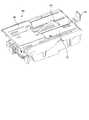
図2は、図1に示した外扉の後方側を示す斜視図である。この図2にも示すように外扉2の左側中央部には販売ユニット10が配設してある。この販売ユニット10は、鋼板を屈曲してなる後面が開口する直方状のユニット本体11を備えている。このユニット本体11の前面が外扉2の前面より前方に突出する態様で配設してある。より詳細に説明すると、販売ユニット10は、自身の前面が外扉2の前面から露出する態様で組み込まれて配設してある。  FIG. 2 is a perspective view showing the rear side of the outer door shown in FIG. As shown in FIG. 2, asales unit 10 is disposed in the left central portion of theouter door 2. Thesales unit 10 includes arectangular unit body 11 having a rear surface opened by bending a steel plate. The front surface of the unitmain body 11 is disposed so as to protrude forward from the front surface of theouter door 2. More specifically, thesales unit 10 is incorporated and arranged in such a manner that its front surface is exposed from the front surface of theouter door 2.

このようなユニット本体11は、正面から見た場合にそれぞれの縁部が屈曲加工されて略矩形状をなしている。かかるユニット本体11の前面には、展示部12、選択ボタン13及び商品取出口14が配設してある。展示部12は、商品見本を展示するための部位である。選択ボタン13は、利用者が購入商品を選択するための押ボタンスイッチであり、展示部12に展示される商品見本毎に用意してある。商品取出口14は、ユニット本体11の前面の中央域下部に形成された開口で、内部から払い出された商品を利用者が受け取るための開口である。尚、この選択ボタン13が押下された場合、その旨の信号は、自動販売機本体に搭載されている後述する制御装置103に与えられることになる。  When viewed from the front, such a unitmain body 11 has a substantially rectangular shape in which each edge is bent. On the front surface of the unitmain body 11, anexhibition section 12, aselection button 13, and aproduct outlet 14 are arranged. Thedisplay unit 12 is a part for displaying product samples. Theselection button 13 is a push button switch for the user to select a purchased product, and is prepared for each product sample displayed in theexhibition unit 12. Theproduct outlet 14 is an opening formed at the lower part of the central area on the front surface of the unitmain body 11, and is an opening for the user to receive the product paid out from the inside. When theselection button 13 is pressed, a signal to that effect is given to a control device 103 (described later) mounted on the vending machine body.

かかるユニット本体11の前面の背面には、商品受部20と、商品受部20を挟んで左右両側に複数(図示の例では3つ)の収納ラック(収納手段)30とが取り付けてある。商品受部20は、商品取出口14の後方域に配設されている。  On the rear surface of the front surface of the unitmain body 11, aproduct receiving unit 20 and a plurality of (three in the illustrated example) storage racks (storage means) 30 are attached to both the left and right sides of theproduct receiving unit 20. Theproduct receiver 20 is disposed in the rear area of theproduct outlet 14.

収納ラック30は、商品受部20よりも上方であって、更に左右側となる個所にそれぞれ配設(図では商品受部20を挟んで右側に上下2段、左側に1段として配設)してある直方状のものである。この収納ラック30は、商品を直積みした状態で上下方向に沿って収納するものであり、上面が開口するとともに、後面31にも該上面開口に連続する態様で下方に向けて舌片状に拡がる開口(舌片状開口)32が形成してある。  Thestorage rack 30 is disposed above theproduct receiving portion 20 and further on the left and right sides (in the figure, the upper and lower two steps are disposed on the right side and the left side is disposed with theproduct receiving portion 20 interposed therebetween). It is a rectangular parallelepiped. Thestorage rack 30 stores products in a vertically stacked state in a state of being directly stacked, and has an upper surface that is open, and arear surface 31 that is continuous with the upper surface and has a tongue-like shape facing downward. An opening (tongue-like opening) 32 that expands is formed.

図3は、図2に示した収納ラック30の内部構造を後方側から示す断面背面図である。尚、ハッチングは省略している。ここで例示する収納ラック30は、商品受部20よりも右側上部域に配設されたものを示している。このような収納ラック30は、最下段に払出機構(払出手段)40が配設してある。払出機構40は、図4に示すように、商品を直積みした状態で載置するための載置台41を備えるとともに、モータの駆動により載置台41の上面を左右方向に沿って進出移動及び退行移動するスライダ42を備えている。ここで、図4中の符号43は、売切検知スイッチである。売切検知スイッチ43は、自身の上に商品が載置される場合には、該商品の自重により載置台41よりも下方に位置してオフ状態となる。その一方、自身の上に商品が載置されない場合には、載置台41よりも上方に位置してオン状態となり、商品が売り切れた旨を後述する制御基板106を通じて上記制御装置103に与えるものである。  FIG. 3 is a cross-sectional rear view showing the internal structure of thestorage rack 30 shown in FIG. 2 from the rear side. Note that hatching is omitted. Thestorage rack 30 illustrated here is the one disposed in the upper right region from theproduct receiving portion 20. Such astorage rack 30 is provided with a payout mechanism (payout means) 40 at the lowest level. As shown in FIG. 4, thepayout mechanism 40 includes a mounting table 41 for mounting products in a directly stacked state, and moves and retreats the upper surface of the mounting table 41 along the left-right direction by driving a motor. A movingslider 42 is provided. Here,reference numeral 43 in FIG. 4 is a sold-out detection switch. When a product is placed on itself, the sold-outdetection switch 43 is positioned below the placement table 41 and is turned off due to the weight of the product. On the other hand, when the product is not placed on itself, it is positioned above the placement table 41 and is turned on to give thecontrol device 103 that the product has been sold through thecontrol board 106 described later. is there.

このような収納ラック30においては、制御装置103から販売指令が与えられた場合に、モータが駆動することにより、図5に示すように、スライダ42が左方向に沿って進出移動し、最下位の商品W1に当接して該商品W1を左方向に押し出す。このとき最下位から2番目の商品W2は、その左端がストッパ片33に当接することにより、最下位の商品W1と同じように左方向に向けて移動することが規制される。  In such astorage rack 30, when a sales command is given from thecontrol device 103, the motor is driven, so that theslider 42 moves forward in the left direction as shown in FIG. The product W1 is pushed leftward in contact with the product W1. At this time, when the left end of the second lowest product W2 comes into contact with thestopper piece 33, the second product W2 is restricted from moving in the left direction in the same manner as the lowest product W1.

また、図中の符号44は、規制部材である。規制部材44は、常態においては載置台41よりも上方に突出した姿勢となり(図3及び図4参照)、載置台41に載置されて収納される商品が払い出されてしまうことを回避しており、販売指令が与えられた場合には、載置台41よりも下方に退避した姿勢となり(図5参照)、スライダ42による商品の払い出しを許容するものである。  Moreover, the code |symbol 44 in a figure is a control member. The restrictingmember 44 normally has a posture projecting upward from the mounting table 41 (see FIGS. 3 and 4), and avoids paying out a product placed on the mounting table 41 and stored. When the sales instruction is given, the posture is retracted downward from the mounting table 41 (see FIG. 5), and the product is allowed to be paid out by theslider 42.

そして、図6に示すようにスライダ42により押し出された商品W1は、商品受部20に払い出され、該商品取出口14を通じて利用者が取り出し可能な状態になる。かかるスライダ42が最下位の商品W1を押し出す場合でも、図6に示すように該スライダ42の上面には最下位から2番目の商品W2が載置しており、スライダ42が右方向に向けて退行移動して初期位置に戻ると、当該商品が載置台41に載置されて最下位の商品として収納されることになる。  Then, as shown in FIG. 6, the product W <b> 1 pushed out by theslider 42 is paid out to theproduct receiving unit 20 and can be taken out by the user through theproduct outlet 14. Even when theslider 42 pushes out the lowest product W1, as shown in FIG. 6, the second product W2 from the lowest is placed on the upper surface of theslider 42, and theslider 42 faces rightward. When retreating and returning to the initial position, the product is placed on the mounting table 41 and stored as the lowest product.

次に、上述した販売ユニット10の取付手順について説明する。  Next, a procedure for attaching thesales unit 10 will be described.

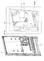
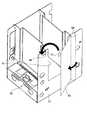
図7は、販売ユニットが取り付けられる以前の外扉の後方側を示す斜視図である。かかる外扉2における左側中央部には、電源装置101、インバータ102、制御装置103、リモコン104が配設してある。尚、図には明示していないが、外扉2の左側中央部の前面にはポスターパネルを表示するポスター部が設けられており、かかるポスター部の背面のスペースに電源装置101、インバータ102、制御装置103、リモコン104が配設してある。つまり、外扉2のかかるポスター部が配設される個所には、予め矩形状の開口2a(図8参照)が形成してあり、この開口2aが透明板で覆われている。そして、ポスターパネルを展示する矩形状の板金からなるポスター展示台100がディスプレイウィンドウ3の背面を形成する中扉21の左下縁に取り付けられ、ポスター展示台100の背面に電源装置101、インバータ102、制御装置103、リモコン104等の電装品が組み付けられている。尚、インバータ102はディスプレイウィンドウ3の照明用光源としての蛍光灯(不図示)に電力を供給して当該蛍光灯を点消灯するものであり、リモコン104は庫内の商品と選択ボタンとの割り付け等の設定を行うものである。  FIG. 7 is a perspective view showing the rear side of the outer door before the sales unit is attached. Apower supply device 101, aninverter 102, acontrol device 103, and aremote controller 104 are disposed at the left central portion of theouter door 2. Although not explicitly shown in the figure, a poster section for displaying a poster panel is provided in front of the left central portion of theouter door 2, and apower supply device 101, aninverter 102, Acontrol device 103 and aremote controller 104 are provided. That is, arectangular opening 2a (see FIG. 8) is formed in advance at a place where the poster portion of theouter door 2 is disposed, and theopening 2a is covered with a transparent plate. A poster display stand 100 made of rectangular sheet metal for displaying the poster panel is attached to the lower left edge of themiddle door 21 forming the back of thedisplay window 3, and apower supply device 101, aninverter 102, Electrical components such as thecontrol device 103 and theremote controller 104 are assembled. Theinverter 102 supplies power to a fluorescent lamp (not shown) as an illumination light source of thedisplay window 3 to turn on / off the fluorescent lamp, and theremote control 104 allocates a product in the warehouse and a selection button. Etc. are set.

電源装置101、インバータ102、制御装置103、リモコン104等の電装品が組み付けられたポスター展示台100及び開口2aを覆う透明板を一旦取り外す、つまり、ポスター部を取り外すことにより、図8に示すように矩形状の開口2aが表出し、図9に示すようにこの矩形状開口2aの開口縁部に固定金50を取り付ける。固定金50を取り付けた後、図10に示すように、一旦取り外したポスター展示台100に組み付けられていた電装品のうちインバータ102を内蔵する筐体105を中扉21の左下縁、すなわち、矩形状開口2aの左側上部の背後となる個所に取り付ける。またインバータ102以外の電装品、電源装置101は外扉2の背面下部、リモコン104及び制御装置103は、外扉2の背面における矩形状開口2aの右側個所に取り付ける。また、販売ユニット10の各構成機器の動作を制御するための制御基板106を電源装置101の右側個所に取り付ける。尚、筐体105はインバータ102を中扉21に取り付けるための取付部材を構成するものであり、筐体に限るものではない。  As shown in FIG. 8, the poster display stand 100 on which electrical components such as thepower supply device 101, theinverter 102, thecontrol device 103, and theremote controller 104 are assembled and the transparent plate covering theopening 2a are temporarily removed, that is, the poster portion is removed. Arectangular opening 2a appears, and a fixedmetal 50 is attached to the opening edge of therectangular opening 2a as shown in FIG. After the fixedmetal 50 is attached, as shown in FIG. 10, among the electrical components that have been assembled to the poster display stand 100 that has been once removed, thecasing 105 containing theinverter 102 is connected to the lower left edge of theinner door 21, that is, rectangular. It is attached to a location behind the upper left part of the shape opening 2a. Further, the electrical components other than theinverter 102, thepower supply device 101 is attached to the lower rear portion of theouter door 2, and theremote controller 104 and thecontrol device 103 are attached to the right side of therectangular opening 2 a on the rear surface of theouter door 2. Further, acontrol board 106 for controlling the operation of each component device of thesales unit 10 is attached to the right side portion of thepower supply device 101. Thehousing 105 constitutes an attachment member for attaching theinverter 102 to theinner door 21, and is not limited to the housing.

図11に示すように、矩形状開口2aの前方側よりユニット本体11を進入させ、ユニット本体11と固定金50とを図示せぬ締結手段により締結させることにより、図12に示すように販売ユニット10が矩形状開口2aを貫通する態様で組み込まれて配設される。  As shown in FIG. 11, the unitmain body 11 is entered from the front side of therectangular opening 2a, and the unitmain body 11 and the fixingmetal 50 are fastened by fastening means (not shown), so that the sales unit as shown in FIG. 10 is incorporated and disposed in such a manner as to penetrate therectangular opening 2a.

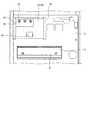
図13は、販売ユニット10が組み込まれる前の状態と、販売ユニット10が組み込まれた状態との自動販売機の内部構造を模式的に示す模式図であり、(a)が販売ユニット10が組み込まれる前の状態を示し、(b)が販売ユニット10が組み込まれた状態を示しており、図13において符号22は、インバータ102とディスプレイウィンドウ3の照明用蛍光灯との間の配線を示している。かかる図13からも明らかなように、販売ユニット10は、自身のユニット本体11が、外扉2のポスター部背後に設けられていたインバータ102を除く電装品を他所へ移動させるとともに外扉2に設けられたポスター部を取り除くことにより表出した矩形状開口2aを貫通する態様で配設されたものである。つまり、ディスプレイウィンドウ3に延在する配線22に対してインバータ102を外扉2の下方領域の空きスペースに移動させようとすると当然のことながら配線22の長さが足りないことから配線22自体を取り替える必要があり、このようなインバータ102と蛍光灯との間の配線22の取り替えには手間がかかり煩雑である一方、インバータ102を除く電装品は外扉2の下方領域の空きスペースに移動させた場合にも配線(の長さ)には余裕がある。そこで、従前の配線22をそのまま利用するためにインバータ102のみをあまり移動させることなくインバータ102を除く電装品を移動させることにより形成された空きスペースに販売ユニット10を組み込んで配設している。  FIG. 13 is a schematic view schematically showing the internal structure of the vending machine in a state before thesales unit 10 is assembled and a state in which thesales unit 10 is incorporated. FIG. (B) shows a state in which thesales unit 10 is incorporated, and in FIG. 13,reference numeral 22 denotes a wiring between theinverter 102 and the fluorescent lamp for illumination of thedisplay window 3. Yes. As apparent from FIG. 13, thesales unit 10 has its own unitmain body 11 moving the electrical components except for theinverter 102 provided behind the poster portion of theouter door 2 to another place and moving it to theouter door 2. It is arranged in such a manner as to penetrate through therectangular opening 2a exposed by removing the provided poster portion. That is, if theinverter 102 is moved to an empty space below theouter door 2 with respect to thewiring 22 extending to thedisplay window 3, thewiring 22 itself is naturally short because the length of thewiring 22 is insufficient. The replacement of thewiring 22 between theinverter 102 and the fluorescent lamp is troublesome and complicated. On the other hand, the electrical components other than theinverter 102 are moved to an empty space below theouter door 2. Even in the case where there is, there is a margin in the wiring (length). Therefore, in order to use theconventional wiring 22 as it is, thesales unit 10 is installed in a vacant space formed by moving the electrical components excluding theinverter 102 without moving only theinverter 102 so much.

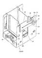
図14は、外扉2の前面から突出するユニット本体11を拡大して示す拡大斜視図である。この図14に示すように、ユニット本体11は、鋼板を屈曲して形成したものであり、それぞれの頂部15には切り欠きが形成してある。そして、図15及び図16に示すように、予めユニット本体11のうち外扉2の前面から突出する矩形状の突出部分の一対の側縁部を覆う態様で、4つの頂部15を被覆する樹脂製の化粧枠材16が図示せぬ締結手段により締結されることにより配設してある。  FIG. 14 is an enlarged perspective view showing the unitmain body 11 protruding from the front surface of theouter door 2 in an enlarged manner. As shown in FIG. 14, the unitmain body 11 is formed by bending a steel plate, and a notch is formed in eachtop portion 15. Then, as shown in FIGS. 15 and 16, a resin that covers the fourtop portions 15 in a manner that covers a pair of side edges of a rectangular protruding portion that protrudes from the front surface of theouter door 2 in theunit body 11 in advance. Thedecorative frame material 16 made of metal is disposed by being fastened by fastening means (not shown).

図17は、外扉2に組み込まれて配設された販売ユニット10の要部を拡大して示す斜視図である。この図17に示すように、販売ユニット10を構成する複数(図示の例では3つ)の収納ラック30のうち、商品受部20の左側上部域に配設される収納ラック30a、すなわちインバータ102を内蔵する筐体105の下方に位置する収納ラック30aは、商品の収容数を増やすために上面開口が筐体105に近接して位置するように形成されていることから上面開口から商品を補充するのが困難であることから後面31に補充用開口34が形成してある。補充用開口34は、舌片状開口32に連続する態様で、該舌片状開口32の上部に該開口32よりも左右に幅広に形成してある。このような補充用開口34は、収納ラック30aに収納する商品の通過を許容するものであり、該開口34を通じて商品の補充を可能にするものである。  FIG. 17 is an enlarged perspective view showing a main part of thesales unit 10 installed and arranged in theouter door 2. As shown in FIG. 17, among a plurality of (three in the illustrated example) storage racks 30 constituting thesales unit 10, astorage rack 30 a disposed in the upper left area of theproduct receiving unit 20, that is, aninverter 102. Thestorage rack 30a located below thehousing 105 containing the product is replenished with goods from the top opening because the top opening is formed close to thehousing 105 in order to increase the number of goods accommodated. Since it is difficult to do so, areplenishment opening 34 is formed in therear surface 31. Thereplenishment opening 34 is formed so as to be continuous with the tongue-like opening 32 and wider at the upper part of the tongue-like opening 32 to the left and right of theopening 32. Such areplenishment opening 34 allows passage of merchandise stored in thestorage rack 30 a, and enables replenishment of merchandise through theopening 34.

図18〜図20は、それぞれ図17に示した収納ラック30aを示す斜視図である。ここで例示する収納ラック30aの後面31には、ストッパ部材35が揺動可能に配設してある。ストッパ部材35は、鋼板を加工して形成した略平板状のものであり、基端部35aに長孔部351及び係合縁部352が設けてある。長孔部351は、左右方向が長手方向となる態様で形成してあり、後面31に配設された段付きネジ36を挿通させている。係合縁部352は、基端部35aの下縁に形成してあり、長孔部351を挿通する段付きネジ36が該長孔部351の右端側に位置する場合に、後面31に配設された係止ネジ(係止部材)37と係合するものである。つまり、図18に示す状態では、ストッパ部材35は、自身の端部(基端部35a:係合縁部352)が係止ネジ37と係合状態にある。このように係合縁部352が係止ネジ37と係合状態にある場合、ストッパ部材35は、左右方向に沿って延在し、自身の先端部35bが補充用開口34を覆って閉成してある。  18 to 20 are perspective views showing thestorage rack 30a shown in FIG. Astopper member 35 is swingably disposed on therear surface 31 of thestorage rack 30a illustrated here. Thestopper member 35 has a substantially flat plate shape formed by processing a steel plate, and is provided with along hole portion 351 and anengaging edge portion 352 in thebase end portion 35a. Thelong hole portion 351 is formed in such a manner that the left-right direction is the longitudinal direction, and a steppedscrew 36 disposed on therear surface 31 is inserted therethrough. The engagingedge portion 352 is formed on the lower edge of thebase end portion 35a. When the steppedscrew 36 that passes through thelong hole portion 351 is located on the right end side of thelong hole portion 351, the engagingedge portion 352 is arranged on therear surface 31. It engages with a provided locking screw (locking member) 37. That is, in the state shown in FIG. 18, thestopper member 35 is in an engaged state with the lockingscrew 37 at its own end (base end 35 a: engagement edge 352). When theengagement edge 352 is in engagement with the lockingscrew 37 in this way, thestopper member 35 extends along the left-right direction, and itsown tip 35b covers thereplenishment opening 34 and is closed. It is.

図19に示すように、ストッパ部材35を右方向に向けて移動させて、段付きネジ36を相対的に移動させて長孔部351の左端側に位置させると、係合縁部352は係止ネジ37から離脱し、係合状態が解除される。このように係合状態が解除されると、ストッパ部材35は、自身の自重により段付きネジ36の軸心回りに下方に向けて揺動し、図20に示すように補充用開口34を開成するものである。このようにストッパ部材35は、後面31に対して該後面31の面方向に沿って揺動可能に配設され、自身の基端部35a(係合縁部352)が係止ネジ37と係合状態にある場合には補充用開口34を閉成する一方、係合状態が解除された場合には自重により揺動して補充用開口34を開成するものである。  As shown in FIG. 19, when thestopper member 35 is moved rightward and the steppedscrew 36 is relatively moved to be positioned on the left end side of thelong hole portion 351, the engagingedge portion 352 is engaged. It disengages from theset screw 37 and the engaged state is released. When the engaged state is released in this way, thestopper member 35 swings downward about the axis of the steppedscrew 36 by its own weight, and opens thereplenishment opening 34 as shown in FIG. To do. Thus, thestopper member 35 is disposed so as to be swingable with respect to therear surface 31 along the surface direction of therear surface 31, and itsbase end portion 35 a (engagement edge portion 352) is engaged with the lockingscrew 37. In the combined state, thereplenishment opening 34 is closed, and when the engaged state is released, thereplenishment opening 34 is opened by swinging by its own weight.

このようにストッパ部材35が自身の自重により下方に向けて揺動する場合、ストッパ部材35の下縁部の一部が係止ネジ37に当接してそれ以上揺動することが規制されている。つまり、ストッパ部材35の揺動域は、収納ラック30aの左右幅から突出しないように調整してある。  When thestopper member 35 swings downward by its own weight as described above, it is restricted that a part of the lower edge portion of thestopper member 35 abuts on the lockingscrew 37 and swings further. . That is, the swing region of thestopper member 35 is adjusted so as not to protrude from the lateral width of thestorage rack 30a.

以上のような構成を有する販売ユニット10を備えた自動販売機においては、かかる販売ユニット10の商品補充を行う場合には、外扉2を開動作させた後に、図21に示すように、商品受部20の右側上部域に配設された2段の収納ラック30では、上面開口より商品を進入させて、払出機構40の載置台41に商品を順次載置させて上下方向に沿って直積み状態に収納させることができる。一方、商品受部20の左側上部域に配設された収納ラック30aでは、ストッパ部材35を自身の自重により揺動させて開成した補充用開口34より商品を進入させて、払出機構40の載置台41に商品を順次載置させて上下方向に沿って直積み状態に収納させることができる。それぞれの収納ラック30において商品が収納された後、ストッパ部材35を上方に向けて揺動させ、更に左方向に向けて移動させることに係合縁部352が係止ネジ37と係合し、ストッパ部材35は補充用開口34を閉成する。そして、外扉2を閉動作させる。  In the vending machine including thesales unit 10 having the above-described configuration, when replenishing the product of thesales unit 10, as shown in FIG. In the two-stage storage rack 30 disposed in the upper right area of the receivingunit 20, the products are entered from the upper surface opening, and the products are sequentially placed on the placing table 41 of thepayout mechanism 40, and are moved along the vertical direction. It can be stored in a stacked state. On the other hand, in thestorage rack 30a disposed in the upper left region of theproduct receiving unit 20, the product is introduced from thereplenishment opening 34 formed by swinging thestopper member 35 by its own weight, and thedelivery mechanism 40 is mounted. Products can be placed on the table 41 sequentially and stored in a vertically stacked state along the vertical direction. After the product is stored in eachstorage rack 30, the engagingedge 352 engages with the lockingscrew 37 to swing thestopper member 35 upward and move it further to the left. Thestopper member 35 closes thereplenishment opening 34. Then, theouter door 2 is closed.

そして、当該自動販売機において販売ユニット10に収納された商品を販売するのに十分な金銭が硬貨投入口4若しくは紙幣挿入口5を通じて投入された場合、販売ユニット10は、制御装置103からの指令に応じて選択ボタン13を点灯させる。そして、いずれかの選択ボタン13が利用者に押下されると、押下された旨が制御装置103に与えられ、制御装置103から制御基板106を通じて選択された商品を収納する収納ラック30の払出機構40に販売指令が与えられる。かかる販売指令が与えられた払出機構40は、モータの駆動によりスライダ42が進出移動する(商品受部20の右側上部域に配設された収納ラック30ではスライダ42が左方向に向けて進出移動し、商品受部20の左側上部域に配設された収納ラック30aではスライダ42が右方向に向けて進出移動する。)。  When the money stored in the vending machine is sold through thecoin insertion slot 4 or thebill insertion slot 5, thesales unit 10 receives a command from thecontrol device 103. In response to this, theselection button 13 is turned on. When one of theselection buttons 13 is pressed by the user, thecontrol device 103 is notified that theselection button 13 has been pressed, and the payout mechanism of thestorage rack 30 that stores the product selected from thecontrol device 103 through thecontrol board 106. 40 is given a sales order. In thepayout mechanism 40 to which such a sales instruction is given, theslider 42 advances and moves by driving the motor (in thestorage rack 30 disposed in the upper right area of theproduct receiving unit 20, theslider 42 moves toward the left. Then, in thestorage rack 30a disposed in the upper left area of theproduct receiving portion 20, theslider 42 moves forward in the right direction.

進出移動するスライダ42が最下位に収納される商品に当接して、該商品を押し出すことにより、該商品は、商品受部20に払い出され、商品取出口14を通じて取り出し可能な状態になる(図22参照)。  The advancingslider 42 comes into contact with the product stored at the lowest position and pushes out the product, whereby the product is paid out to theproduct receiving unit 20 and can be taken out through the product outlet 14 ( (See FIG. 22).

以上説明したように本発明の実施の形態である自動販売機によれば、外扉2に組み込まれて配設される販売ユニット10が、収納ラック30が商品を直積みした状態で収納し、かつ払出機構40が販売指令が与えられた場合に、左右方向に沿って移動して収納ラック30により収納された最下位の商品(W1)に当接して、該商品を商品取出口14の後方域にある商品受部20に払い出すので、従来のように前後方向に沿って移動する押出部材を必要とせず、販売ユニット10の前後方向の寸法を小さくすることができる。従って、販売ユニット10の前後方向の寸法を低減させて、外扉2より前方に突出する販売ユニット10の突出長さ、すなわち外扉2の前面から販売ユニット10の前面までの突出長さを小さくすることができる。また商品受部20は左右に配設された複数の収納ラック30に共通の商品払出通路となるので、狭いスペースに複数の収納ラックを配置して複数種類の商品を販売することが可能となる。  As described above, according to the vending machine according to the embodiment of the present invention, thesales unit 10 incorporated and disposed in theouter door 2 stores the product in a state where thestorage rack 30 directly stacks the products, When thedispensing mechanism 40 is given a sales command, it moves along the left-right direction and comes into contact with the lowest product (W1) stored in thestorage rack 30 to place the product behind theproduct outlet 14. Since it pays out to theproduct receiving part 20 in the area, the pushing member that moves in the front-rear direction as in the prior art is not required, and the front-rear dimension of thesales unit 10 can be reduced. Accordingly, the longitudinal dimension of thesales unit 10 is reduced, and the protruding length of thesales unit 10 protruding forward from theouter door 2, that is, the protruding length from the front surface of theouter door 2 to the front surface of thesales unit 10 is reduced. can do. Further, since theproduct receiving unit 20 serves as a product delivery path common to the plurality ofstorage racks 30 arranged on the left and right, it is possible to arrange a plurality of storage racks in a narrow space and sell a plurality of types of products. .

上記自動販売機によれば、販売ユニット10は、自身のユニット本体11が、外扉2に設けられていたインバータ102を除く電装品を他所へ移動させて空きスペースを確保するとともに外扉2に設けられたポスター部を取り除くことにより表出した矩形状開口2aを貫通する態様で配設されたものであるので、外扉2より前方に突出する突出長さをより小さくすることができる。特に、インバータ102については上方に僅かに移動させただけなので、配線22を大きく変更する必要がなく、販売ユニット10を配設する時間の短縮化を図ることができる。更に、配線22を取り替えることなくそのまま使用できることから従前の自動販売機の外扉2に対しても適用可能であるので、汎用性に優れたものとなる。  According to the vending machine, thesales unit 10 has its own unitmain body 11 moved the electrical components other than theinverter 102 provided in theouter door 2 to other places to secure an empty space and to theouter door 2. Since it is arranged in such a manner as to penetrate therectangular opening 2a exposed by removing the provided poster portion, the protruding length protruding forward from theouter door 2 can be further reduced. In particular, since theinverter 102 is slightly moved upward, it is not necessary to change thewiring 22 greatly, and the time for arranging thesales unit 10 can be shortened. Furthermore, since thewiring 22 can be used as it is without being replaced, it can be applied to theouter door 2 of a conventional vending machine, so that it has excellent versatility.

上記自動販売機によれば、ストッパ部材35は、後面31に対して該後面31の面方向に沿って揺動可能に配設され、自身の基端部35a(係合縁部352)が係止ネジ37と係合状態にある場合には補充用開口34を閉成する一方、係合状態が解除された場合には自重により揺動して補充用開口34を開成するので、補充用開口34を通じて商品を補充することができ、商品のローディング作業を容易なものとすることができる。しかも、後面31に設けた補充用開口34を通じて補充を行うので、収納ラック30の高さ寸法を設置個所で許容される最大限の大きさにすることができ、商品の収納数を増大化させることができる。また、ストッパ部材35が、係止ネジ37と係合状態にある場合には補充用開口34を閉成させるので、外扉2の開閉動作により収納する商品が落下してしまう虞れがない。従って、販売ユニット10の前後方向の寸法を低減させて外扉2より前方に突出する突出長さを小さくすることができるとともに、商品の収納数の増大化、並びに外扉2の開閉動作により収納する商品が落下してしまうことを防止できる。  According to the vending machine, thestopper member 35 is disposed so as to be swingable along the surface direction of therear surface 31 with respect to therear surface 31, and its ownbase end portion 35a (engagement edge portion 352) is engaged. When the engaged state is engaged with theset screw 37, thereplenishment opening 34 is closed. When the engaged state is released, thereplenishment opening 34 is opened by swinging by its own weight. The product can be replenished through 34, and the loading operation of the product can be facilitated. In addition, since the replenishment is performed through thereplenishment opening 34 provided on therear surface 31, the height of thestorage rack 30 can be set to the maximum allowable at the installation location, and the number of products stored can be increased. be able to. Further, since thereplenishment opening 34 is closed when thestopper member 35 is engaged with the lockingscrew 37, there is no possibility that the product stored by the opening / closing operation of theouter door 2 is dropped. Therefore, it is possible to reduce the length of thesales unit 10 in the front-rear direction and reduce the protruding length protruding forward from theouter door 2, and to store the product by increasing the number of products stored and opening / closing theouter door 2. Can prevent the product to be dropped.

上記自動販売機によれば、樹脂製の化粧枠材16がユニット本体11のうち外扉2の前面から突出する矩形状の突出部分の一対の側縁部を覆う態様で、4つの頂部15を被覆するので、歩行者や利用者等が外扉2の前面から前方に突出するユニット本体11に接触して怪我等してしまうことを回避するとともに、外扉2に設けられた商品取出口7を開閉する商品取出扉8を大きく開放した際に商品取出扉8が衝突することとなるが、この場合にも化粧枠体16によって透明な商品取出扉8に傷が付いたり商品取出扉8が破損してしまうことを防止することができる。特に、ユニット本体11のうち外扉2から前方に突出する部分の頂部15については、球面状に仕上げるための溶接等の特殊な表面処理を必要としないので、作業工程の簡素化を図ることができ、見栄え等の意匠性をも向上させることができる。  According to the vending machine, the fourtop portions 15 are formed in such a manner that thedecorative frame material 16 made of resin covers a pair of side edges of a rectangular protruding portion protruding from the front surface of theouter door 2 in the unitmain body 11. Since it coat | covers, while avoiding a pedestrian, a user, etc. contacting the unitmain body 11 which protrudes ahead from the front surface of theouter door 2 and being injured etc., thegoods outlet 7 provided in theouter door 2 is provided. The product take-outdoor 8 collides when the product take-outdoor 8 that opens and closes the door is opened widely. In this case, the transparent product take-outdoor 8 is damaged by thedecorative frame 16 or the product take-outdoor 8 It is possible to prevent damage. In particular, the top 15 of the portion of theunit body 11 that protrudes forward from theouter door 2 does not require special surface treatment such as welding for finishing it into a spherical shape, so that the work process can be simplified. And design properties such as appearance can be improved.

上記自動販売機によれば、販売ユニット10は、制御基板106を通じて本体キャビネット1に配設された制御装置103に電気的に接続されており、該制御装置103からの指令に応じて各種機器が駆動するので、独自に制御装置103を必要とせず、コストの低減化を図ることもできる。  According to the vending machine, thesales unit 10 is electrically connected to thecontrol device 103 disposed in themain body cabinet 1 through thecontrol board 106, and various devices are connected in accordance with commands from thecontrol device 103. Since it is driven, thecontrol device 103 is not required and cost can be reduced.

以上、本発明の好適な実施の形態について説明したが、本発明はこれに限定されるものではなく、種々の変更を行うことができる。  The preferred embodiment of the present invention has been described above, but the present invention is not limited to this, and various modifications can be made.

上述した実施の形態では、化粧枠材16がユニット本体11のうち外扉2の前面から突出する矩形状の突出部分の一対の側縁部を覆う態様で配設されていたが、本発明はこれに限定されず、化粧枠材が互いに対向するいずれかの一対の縁部を覆う態様で4つの頂部を被覆すればよく、上記突出部分の上縁部と下縁部とを覆う態様で配設されていても構わないし、上記突出部の縁部全てを覆う態様で配設されていても構わない。このような構成によっても、歩行者や利用者等が外扉の前面から前方に突出するユニット本体に接触して怪我等してしまうことを回避するとともに、外扉に設けられた商品取出口を開閉する商品取出扉が破損してしまうことを防止することができる。  In the above-described embodiment, thedecorative frame member 16 is disposed in a manner covering the pair of side edges of the rectangular protruding portion that protrudes from the front surface of theouter door 2 in the unitmain body 11. However, the present invention is not limited to this, and it is only necessary to cover the four top portions in a manner in which the decorative frame material covers any pair of edges facing each other, and the decorative frame material is arranged in a manner to cover the upper and lower edges of the protruding portion. It may be provided, or may be arranged in a manner covering the entire edge of the protruding portion. Even with such a configuration, pedestrians, users, etc. can avoid being injured by coming into contact with the unit body projecting forward from the front surface of the outer door, and the product outlet provided on the outer door can be removed. It can prevent that the goods extraction door to open and close is damaged.

上述した実施の形態では、商品受部20の左側上部域に配設された収納ラック30aのみに補充用開口34が形成され、かつストッパ部材35が揺動可能に配設されていたが、本発明においては、かかる収納ラック30aだけに限られず、商品受部の右側上部域に配設された収納ラックにも補充用開口が形成されたり、ストッパ部材が配設されたりしても良い。また、上述したストッパ部材35は、後面31に対して該後面31の面方向に沿って揺動可能に配設されていたが、本発明においては、図23に示すように、ストッパ部材65が後面31に設けた軸状部66の軸心回りに前後方向に沿って揺動可能に配設されていても良い。ストッパ部材65の先端側(自由端側)の上部に係合片67が形成されており、係合片67が後面31に形成された係止孔部68に進入した場合にストッパ部材65は、係合状態になって補充用開口34を閉成する。  In the above-described embodiment, thereplenishment opening 34 is formed only in thestorage rack 30a disposed in the upper left area of theproduct receiving unit 20, and thestopper member 35 is disposed so as to be swingable. In the present invention, not only thestorage rack 30a but also a storage rack disposed in the upper right area of the product receiving portion may be provided with a replenishment opening or a stopper member. In addition, thestopper member 35 described above is disposed so as to be swingable along the surface direction of therear surface 31 with respect to therear surface 31. However, in the present invention, as shown in FIG. It may be arranged so as to be swingable along the front-rear direction around the axis of the shaft-like portion 66 provided on therear surface 31. An engagingpiece 67 is formed on the top of the front end side (free end side) of thestopper member 65, and when the engagingpiece 67 enters the lockinghole 68 formed on therear surface 31, thestopper member 65 Thereplenishment opening 34 is closed by engaging.

また、上述した実施の形態では、従前の自動販売機の外扉2に対しても適用可能、つまり、従前の自動販売機の外扉2におけるディスプレイウィンドウ3の照明用蛍光灯の配線をそのまま利用できるようにするためにインバータ102を販売ユニット10の背後の個所に残した場合について説明したが、新規に自動販売機を製造する場合にはインバータ102とディスプレイウィンドウ3の照明用蛍光灯との配線を変更すればインバータ102を販売ユニット10の背後ではなく、外扉2の下方領域の空きスペースに移動させることができる。この場合には販売ユニット10として商品受部20を挟んで左右両側にそれぞれ上下2段の収納ラック30を配設することができるので販売する商品の種類を増やすことができる。また、この場合にも販売ユニット10を取り外すことによりポスター部を組み付けることができる。  Moreover, in embodiment mentioned above, it is applicable also to theouter door 2 of a conventional vending machine, that is, using the wiring of the fluorescent lamp for illumination of thedisplay window 3 in theouter door 2 of a conventional vending machine as it is. The case where theinverter 102 is left behind thesales unit 10 so as to be able to be described has been described. However, when a vending machine is newly manufactured, the wiring between theinverter 102 and the fluorescent lamp for illumination of thedisplay window 3 is performed. Is changed, theinverter 102 can be moved not to the back of thesales unit 10 but to an empty space in the lower region of theouter door 2. In this case, since the upper andlower storage racks 30 can be arranged on the left and right sides of theproduct receiving unit 20 as thesales unit 10, the types of products to be sold can be increased. Also in this case, the poster unit can be assembled by removing thesales unit 10.

以上のように、本発明に係る自動販売機は、例えば缶入り飲料やペットボトル入り飲料等の商品を販売するのに有用である。  As described above, the vending machine according to the present invention is useful for selling products such as canned drinks and plastic bottled drinks.

1 本体キャビネット
2 外扉(扉体)
2a 矩形状開口
7 商品取出口
10 販売ユニット
11 ユニット本体
12 展示部
13 選択ボタン
14 商品取出口
15 頂部
16 化粧枠材
20 商品受部
30 収納ラック(収納手段)
30a 収納ラック
31 後面
32 舌片状開口
34 補充用開口
35 ストッパ部材
35a 基端部
35b 先端部
351 長孔部
352 係合縁部
36 段付きネジ
37 係止ネジ(係止部材)
40 払出機構(払出手段)
41 載置台
42 スライダ
43 売切検知スイッチ
33 ストッパ片
44 規制部材
50 固定金
101 電源装置
102 インバータ
103 制御装置
104 リモコン
105 筐体
106 制御基板
1Main body cabinet 2 Outer door (door)
2a Rectangular opening 7Product outlet 10Sales unit 11 Unitmain body 12Display unit 13Selection button 14Product outlet 15Top 16Cosmetic frame material 20Product receiver 30 Storage rack (storage means)
30a Storage rack 31Rear surface 32 Tongue-shapedopening 34Replenishment opening 35Stopper member 35aBase end portion 35bTip end portion 351Long hole portion 352Engagement edge portion 36 Steppedscrew 37 Locking screw (locking member)
40 Dispensing mechanism (dispensing means)
DESCRIPTION OFSYMBOLS 41 Mounting stand 42Slider 43 Sold outdetection switch 33Stopper piece 44Restriction member 50Fixed metal 101Power supply device 102Inverter 103Control device 104Remote control 105Case 106 Control board

Claims (1)

Translated fromJapanese
前面に開口を有した直方状をなし、商品を内部に収納する自動販売機本体と、
前記自動販売機本体の前面開口を開閉する扉体と、
自身の前面が前記扉体の前面から露出する態様で組み込まれ、前記前面の中央域下部に商品取出口が形成された販売ユニットと
を備えた自動販売機において、
前記販売ユニットは、
前記自動販売機本体に収納された商品とは別個の商品を直積みした状態で収納する収納手段と、
販売指令が与えられた場合に左右方向に沿って移動して前記収納手段により収納された最下位の商品に当接して、該商品を前記商品取出口の後方域にある商品受部に払い出す払出手段と
を備え、
前記収納手段は、
自身の後面に形成され、かつ商品を補充するための補充用開口と、
自身の基端部に形成された長孔部に前記後面に配設された段付きネジが挿通することにより、該段付きネジの中心軸回りに自身の先端部が自由端として前記後面の面方向に沿って揺動可能に配設されるものであって、前記基端部の下縁に形成された係合縁部が前記後面に配設された係止部材と係合状態にある場合には揺動が規制されて前記先端部が前記補充用開口の少なくとも一部を閉成する一方、前記係止部材に離隔するよう前記後面の面方向に沿って移動することで前記係合状態が解除された場合には自重により揺動して前記補充用開口を開成するストッパ部材と
を備えたことを特徴とする自動販売機。
A vending machine main body that has a rectangular shape with an opening on the front and stores products inside,
A door body for opening and closing the front opening of the vending machine body;
In a vending machine comprising a sales unit incorporated in a manner in which its front surface is exposed from the front surface of the door body, and a product outlet is formed in a lower central area of the front surface,
The sales unit is
Storage means for storing the products separately from the products stored in the vending machine main body in a directly stacked state;
When a sales instruction is given, the product moves along the left-right direction, abuts against the lowest product stored by the storage means, and pays out the product to a product receiver in the rear area of the product outlet. With a withdrawal means,
The storage means includes
A replenishment opening formed on the back surface of the refill for replenishing goods;
By inserting a stepped screw disposed on the rear surface into a long hole formed in thebase end of itself, the front surface of the rear surface is set as a free end around the central axis of the stepped screw. When the engagement edge formed on the lower edge of the base end portion is in engagement with the locking member disposed on the rear surface, and is disposed so as to be swingable along the direction. The front end portion closes at least a part of the replenishment opening and is moved along the surface direction of the rear surface so as to be separated from the locking member. And a stopper memberthat swings due to its own weight to open the replenishment opening when it is released .
JP2009253350A2009-11-042009-11-04 vending machineExpired - Fee RelatedJP5434487B2 (en)

Priority Applications (1)

Application NumberPriority DateFiling DateTitle
JP2009253350AJP5434487B2 (en)2009-11-042009-11-04 vending machine

Applications Claiming Priority (1)

Application NumberPriority DateFiling DateTitle
JP2009253350AJP5434487B2 (en)2009-11-042009-11-04 vending machine

Publications (2)

Publication NumberPublication Date
JP2011100216A JP2011100216A (en)2011-05-19
JP5434487B2true JP5434487B2 (en)2014-03-05

Family

ID=44191354

Family Applications (1)

Application NumberTitlePriority DateFiling Date
JP2009253350AExpired - Fee RelatedJP5434487B2 (en)2009-11-042009-11-04 vending machine

Country Status (1)

CountryLink
JP (1)JP5434487B2 (en)

Family Cites Families (2)

* Cited by examiner, † Cited by third party
Publication numberPriority datePublication dateAssigneeTitle
JPH10134240A (en)*1996-10-311998-05-22Fuji Electric Co Ltd Vending machine vertical stacking type product storage rack
JP2006099638A (en)*2004-09-302006-04-13Silver Seiko LtdBuilt-in vending machine

Also Published As

Publication numberPublication date
JP2011100216A (en)2011-05-19

Similar Documents

PublicationPublication DateTitle
JP5853526B2 (en) vending machine
JP5668545B2 (en) Product storage device
JP5440102B2 (en) vending machine
JP5434487B2 (en) vending machine
JP5434488B2 (en) vending machine
JP5825442B2 (en) Product storage device
JP5375530B2 (en) vending machine
JP5458866B2 (en) vending machine
JP5458853B2 (en) vending machine
JP5434553B2 (en) vending machine
JP2008108188A (en)Automatic vending machine
JP2011197828A (en)Commodity accommodation device for vending machine
JP5691963B2 (en) vending machine
JP2011123766A (en)Automatic vending machine
JP5012291B2 (en) Product carrying device
JP5742328B2 (en) Product storage device
JP5668546B2 (en) Product storage device
JP2011123768A (en)Automatic vending machine
JP2011123767A (en)Automatic vending machine
JP4631737B2 (en) Vending machine product take-out device
JP4867934B2 (en) vending machine
JP4696961B2 (en) Vending machine product take-out device
JP2009294783A (en)Vending machine
JP2010128548A (en)Automatic dispenser
JP2000090342A (en)Merchandise carry-away device of automatic vending machine

Legal Events

DateCodeTitleDescription
A625Written request for application examination (by other person)

Free format text:JAPANESE INTERMEDIATE CODE: A625

Effective date:20120313

A711Notification of change in applicant

Free format text:JAPANESE INTERMEDIATE CODE: A712

Effective date:20121025

A977Report on retrieval

Free format text:JAPANESE INTERMEDIATE CODE: A971007

Effective date:20130822

A131Notification of reasons for refusal

Free format text:JAPANESE INTERMEDIATE CODE: A131

Effective date:20130827

A521Request for written amendment filed

Free format text:JAPANESE INTERMEDIATE CODE: A523

Effective date:20131023

TRDDDecision of grant or rejection written
A01Written decision to grant a patent or to grant a registration (utility model)

Free format text:JAPANESE INTERMEDIATE CODE: A01

Effective date:20131112

A61First payment of annual fees (during grant procedure)

Free format text:JAPANESE INTERMEDIATE CODE: A61

Effective date:20131125

R150Certificate of patent or registration of utility model

Ref document number:5434487

Country of ref document:JP

Free format text:JAPANESE INTERMEDIATE CODE: R150

Free format text:JAPANESE INTERMEDIATE CODE: R150

R250Receipt of annual fees

Free format text:JAPANESE INTERMEDIATE CODE: R250

R250Receipt of annual fees

Free format text:JAPANESE INTERMEDIATE CODE: R250

R250Receipt of annual fees

Free format text:JAPANESE INTERMEDIATE CODE: R250

R250Receipt of annual fees

Free format text:JAPANESE INTERMEDIATE CODE: R250

R250Receipt of annual fees

Free format text:JAPANESE INTERMEDIATE CODE: R250

R250Receipt of annual fees

Free format text:JAPANESE INTERMEDIATE CODE: R250

LAPSCancellation because of no payment of annual fees

[8]ページ先頭

©2009-2025 Movatter.jp