JP5432396B1 - Film forming apparatus and injector - Google Patents
Film forming apparatus and injectorDownload PDFInfo
- Publication number
- JP5432396B1 JP5432396B1JP2013039728AJP2013039728AJP5432396B1JP 5432396 B1JP5432396 B1JP 5432396B1JP 2013039728 AJP2013039728 AJP 2013039728AJP 2013039728 AJP2013039728 AJP 2013039728AJP 5432396 B1JP5432396 B1JP 5432396B1
- Authority
- JP
- Japan
- Prior art keywords
- gas
- film forming
- injector
- film
- substrate
- Prior art date
- Legal status (The legal status is an assumption and is not a legal conclusion. Google has not performed a legal analysis and makes no representation as to the accuracy of the status listed.)
- Active
Links
Images


Classifications
- C—CHEMISTRY; METALLURGY
- C23—COATING METALLIC MATERIAL; COATING MATERIAL WITH METALLIC MATERIAL; CHEMICAL SURFACE TREATMENT; DIFFUSION TREATMENT OF METALLIC MATERIAL; COATING BY VACUUM EVAPORATION, BY SPUTTERING, BY ION IMPLANTATION OR BY CHEMICAL VAPOUR DEPOSITION, IN GENERAL; INHIBITING CORROSION OF METALLIC MATERIAL OR INCRUSTATION IN GENERAL
- C23C—COATING METALLIC MATERIAL; COATING MATERIAL WITH METALLIC MATERIAL; SURFACE TREATMENT OF METALLIC MATERIAL BY DIFFUSION INTO THE SURFACE, BY CHEMICAL CONVERSION OR SUBSTITUTION; COATING BY VACUUM EVAPORATION, BY SPUTTERING, BY ION IMPLANTATION OR BY CHEMICAL VAPOUR DEPOSITION, IN GENERAL
- C23C16/00—Chemical coating by decomposition of gaseous compounds, without leaving reaction products of surface material in the coating, i.e. chemical vapour deposition [CVD] processes
- C23C16/44—Chemical coating by decomposition of gaseous compounds, without leaving reaction products of surface material in the coating, i.e. chemical vapour deposition [CVD] processes characterised by the method of coating
- C23C16/455—Chemical coating by decomposition of gaseous compounds, without leaving reaction products of surface material in the coating, i.e. chemical vapour deposition [CVD] processes characterised by the method of coating characterised by the method used for introducing gases into reaction chamber or for modifying gas flows in reaction chamber
- C23C16/45563—Gas nozzles
- C23C16/45574—Nozzles for more than one gas
- C—CHEMISTRY; METALLURGY
- C23—COATING METALLIC MATERIAL; COATING MATERIAL WITH METALLIC MATERIAL; CHEMICAL SURFACE TREATMENT; DIFFUSION TREATMENT OF METALLIC MATERIAL; COATING BY VACUUM EVAPORATION, BY SPUTTERING, BY ION IMPLANTATION OR BY CHEMICAL VAPOUR DEPOSITION, IN GENERAL; INHIBITING CORROSION OF METALLIC MATERIAL OR INCRUSTATION IN GENERAL
- C23C—COATING METALLIC MATERIAL; COATING MATERIAL WITH METALLIC MATERIAL; SURFACE TREATMENT OF METALLIC MATERIAL BY DIFFUSION INTO THE SURFACE, BY CHEMICAL CONVERSION OR SUBSTITUTION; COATING BY VACUUM EVAPORATION, BY SPUTTERING, BY ION IMPLANTATION OR BY CHEMICAL VAPOUR DEPOSITION, IN GENERAL
- C23C16/00—Chemical coating by decomposition of gaseous compounds, without leaving reaction products of surface material in the coating, i.e. chemical vapour deposition [CVD] processes
- C23C16/44—Chemical coating by decomposition of gaseous compounds, without leaving reaction products of surface material in the coating, i.e. chemical vapour deposition [CVD] processes characterised by the method of coating
- C23C16/4412—Details relating to the exhausts, e.g. pumps, filters, scrubbers, particle traps
- C—CHEMISTRY; METALLURGY
- C23—COATING METALLIC MATERIAL; COATING MATERIAL WITH METALLIC MATERIAL; CHEMICAL SURFACE TREATMENT; DIFFUSION TREATMENT OF METALLIC MATERIAL; COATING BY VACUUM EVAPORATION, BY SPUTTERING, BY ION IMPLANTATION OR BY CHEMICAL VAPOUR DEPOSITION, IN GENERAL; INHIBITING CORROSION OF METALLIC MATERIAL OR INCRUSTATION IN GENERAL
- C23C—COATING METALLIC MATERIAL; COATING MATERIAL WITH METALLIC MATERIAL; SURFACE TREATMENT OF METALLIC MATERIAL BY DIFFUSION INTO THE SURFACE, BY CHEMICAL CONVERSION OR SUBSTITUTION; COATING BY VACUUM EVAPORATION, BY SPUTTERING, BY ION IMPLANTATION OR BY CHEMICAL VAPOUR DEPOSITION, IN GENERAL
- C23C16/00—Chemical coating by decomposition of gaseous compounds, without leaving reaction products of surface material in the coating, i.e. chemical vapour deposition [CVD] processes
- C23C16/44—Chemical coating by decomposition of gaseous compounds, without leaving reaction products of surface material in the coating, i.e. chemical vapour deposition [CVD] processes characterised by the method of coating
- C23C16/455—Chemical coating by decomposition of gaseous compounds, without leaving reaction products of surface material in the coating, i.e. chemical vapour deposition [CVD] processes characterised by the method of coating characterised by the method used for introducing gases into reaction chamber or for modifying gas flows in reaction chamber
- C23C16/45519—Inert gas curtains
- C—CHEMISTRY; METALLURGY
- C23—COATING METALLIC MATERIAL; COATING MATERIAL WITH METALLIC MATERIAL; CHEMICAL SURFACE TREATMENT; DIFFUSION TREATMENT OF METALLIC MATERIAL; COATING BY VACUUM EVAPORATION, BY SPUTTERING, BY ION IMPLANTATION OR BY CHEMICAL VAPOUR DEPOSITION, IN GENERAL; INHIBITING CORROSION OF METALLIC MATERIAL OR INCRUSTATION IN GENERAL
- C23C—COATING METALLIC MATERIAL; COATING MATERIAL WITH METALLIC MATERIAL; SURFACE TREATMENT OF METALLIC MATERIAL BY DIFFUSION INTO THE SURFACE, BY CHEMICAL CONVERSION OR SUBSTITUTION; COATING BY VACUUM EVAPORATION, BY SPUTTERING, BY ION IMPLANTATION OR BY CHEMICAL VAPOUR DEPOSITION, IN GENERAL
- C23C16/00—Chemical coating by decomposition of gaseous compounds, without leaving reaction products of surface material in the coating, i.e. chemical vapour deposition [CVD] processes
- C23C16/44—Chemical coating by decomposition of gaseous compounds, without leaving reaction products of surface material in the coating, i.e. chemical vapour deposition [CVD] processes characterised by the method of coating
- C23C16/455—Chemical coating by decomposition of gaseous compounds, without leaving reaction products of surface material in the coating, i.e. chemical vapour deposition [CVD] processes characterised by the method of coating characterised by the method used for introducing gases into reaction chamber or for modifying gas flows in reaction chamber
- C23C16/45523—Pulsed gas flow or change of composition over time
- C23C16/45525—Atomic layer deposition [ALD]
- C23C16/45527—Atomic layer deposition [ALD] characterized by the ALD cycle, e.g. different flows or temperatures during half-reactions, unusual pulsing sequence, use of precursor mixtures or auxiliary reactants or activations
- C23C16/45536—Use of plasma, radiation or electromagnetic fields
- C—CHEMISTRY; METALLURGY
- C23—COATING METALLIC MATERIAL; COATING MATERIAL WITH METALLIC MATERIAL; CHEMICAL SURFACE TREATMENT; DIFFUSION TREATMENT OF METALLIC MATERIAL; COATING BY VACUUM EVAPORATION, BY SPUTTERING, BY ION IMPLANTATION OR BY CHEMICAL VAPOUR DEPOSITION, IN GENERAL; INHIBITING CORROSION OF METALLIC MATERIAL OR INCRUSTATION IN GENERAL
- C23C—COATING METALLIC MATERIAL; COATING MATERIAL WITH METALLIC MATERIAL; SURFACE TREATMENT OF METALLIC MATERIAL BY DIFFUSION INTO THE SURFACE, BY CHEMICAL CONVERSION OR SUBSTITUTION; COATING BY VACUUM EVAPORATION, BY SPUTTERING, BY ION IMPLANTATION OR BY CHEMICAL VAPOUR DEPOSITION, IN GENERAL
- C23C16/00—Chemical coating by decomposition of gaseous compounds, without leaving reaction products of surface material in the coating, i.e. chemical vapour deposition [CVD] processes
- C23C16/44—Chemical coating by decomposition of gaseous compounds, without leaving reaction products of surface material in the coating, i.e. chemical vapour deposition [CVD] processes characterised by the method of coating
- C23C16/455—Chemical coating by decomposition of gaseous compounds, without leaving reaction products of surface material in the coating, i.e. chemical vapour deposition [CVD] processes characterised by the method of coating characterised by the method used for introducing gases into reaction chamber or for modifying gas flows in reaction chamber
- C23C16/45523—Pulsed gas flow or change of composition over time
- C23C16/45525—Atomic layer deposition [ALD]
- C23C16/45544—Atomic layer deposition [ALD] characterized by the apparatus
- C—CHEMISTRY; METALLURGY
- C23—COATING METALLIC MATERIAL; COATING MATERIAL WITH METALLIC MATERIAL; CHEMICAL SURFACE TREATMENT; DIFFUSION TREATMENT OF METALLIC MATERIAL; COATING BY VACUUM EVAPORATION, BY SPUTTERING, BY ION IMPLANTATION OR BY CHEMICAL VAPOUR DEPOSITION, IN GENERAL; INHIBITING CORROSION OF METALLIC MATERIAL OR INCRUSTATION IN GENERAL
- C23C—COATING METALLIC MATERIAL; COATING MATERIAL WITH METALLIC MATERIAL; SURFACE TREATMENT OF METALLIC MATERIAL BY DIFFUSION INTO THE SURFACE, BY CHEMICAL CONVERSION OR SUBSTITUTION; COATING BY VACUUM EVAPORATION, BY SPUTTERING, BY ION IMPLANTATION OR BY CHEMICAL VAPOUR DEPOSITION, IN GENERAL
- C23C16/00—Chemical coating by decomposition of gaseous compounds, without leaving reaction products of surface material in the coating, i.e. chemical vapour deposition [CVD] processes
- C23C16/44—Chemical coating by decomposition of gaseous compounds, without leaving reaction products of surface material in the coating, i.e. chemical vapour deposition [CVD] processes characterised by the method of coating
- C23C16/54—Apparatus specially adapted for continuous coating
- C23C16/545—Apparatus specially adapted for continuous coating for coating elongated substrates
- H—ELECTRICITY
- H01—ELECTRIC ELEMENTS
- H01J—ELECTRIC DISCHARGE TUBES OR DISCHARGE LAMPS
- H01J37/00—Discharge tubes with provision for introducing objects or material to be exposed to the discharge, e.g. for the purpose of examination or processing thereof
- H01J37/32—Gas-filled discharge tubes
- H01J37/32009—Arrangements for generation of plasma specially adapted for examination or treatment of objects, e.g. plasma sources
- H01J37/32082—Radio frequency generated discharge
- H01J37/32091—Radio frequency generated discharge the radio frequency energy being capacitively coupled to the plasma
- H—ELECTRICITY
- H01—ELECTRIC ELEMENTS
- H01J—ELECTRIC DISCHARGE TUBES OR DISCHARGE LAMPS
- H01J37/00—Discharge tubes with provision for introducing objects or material to be exposed to the discharge, e.g. for the purpose of examination or processing thereof
- H01J37/32—Gas-filled discharge tubes
- H01J37/32431—Constructional details of the reactor
- H01J37/3244—Gas supply means
- H—ELECTRICITY
- H01—ELECTRIC ELEMENTS
- H01J—ELECTRIC DISCHARGE TUBES OR DISCHARGE LAMPS
- H01J37/00—Discharge tubes with provision for introducing objects or material to be exposed to the discharge, e.g. for the purpose of examination or processing thereof
- H01J37/32—Gas-filled discharge tubes
- H01J37/32431—Constructional details of the reactor
- H01J37/32733—Means for moving the material to be treated
- H01J37/32752—Means for moving the material to be treated for moving the material across the discharge
- H01J37/32761—Continuous moving
- H—ELECTRICITY
- H01—ELECTRIC ELEMENTS
- H01J—ELECTRIC DISCHARGE TUBES OR DISCHARGE LAMPS
- H01J2237/00—Discharge tubes exposing object to beam, e.g. for analysis treatment, etching, imaging
- H01J2237/32—Processing objects by plasma generation
- H01J2237/33—Processing objects by plasma generation characterised by the type of processing
- H01J2237/332—Coating
Landscapes
- Chemical & Material Sciences (AREA)
- Engineering & Computer Science (AREA)
- General Chemical & Material Sciences (AREA)
- Chemical Kinetics & Catalysis (AREA)
- Materials Engineering (AREA)
- Mechanical Engineering (AREA)
- Metallurgy (AREA)
- Organic Chemistry (AREA)
- Physics & Mathematics (AREA)
- Plasma & Fusion (AREA)
- Analytical Chemistry (AREA)
- Electromagnetism (AREA)
- Chemical Vapour Deposition (AREA)
- Plasma Technology (AREA)
- Condensed Matter Physics & Semiconductors (AREA)
- General Physics & Mathematics (AREA)
- Manufacturing & Machinery (AREA)
- Computer Hardware Design (AREA)
- Microelectronics & Electronic Packaging (AREA)
- Power Engineering (AREA)
- Spectroscopy & Molecular Physics (AREA)
Abstract
Translated fromJapaneseDescription
Translated fromJapanese本発明は、原子層単位で基板に薄膜を形成する成膜装置、及びガスを基板に供給するインジェクタに関する。 The present invention relates to a film forming apparatus that forms a thin film on a substrate in units of atomic layers, and an injector that supplies gas to the substrate.
今日、基板に薄膜を形成するとき、形成しようとする薄膜を構成する元素を主成分とする2種類の前駆体を基板上に交互に供給して、すなわち、基板上に原子層単位で薄膜を形成することを複数回繰り返して、所望厚さの膜を形成するALD(Atomic Layer Deposition)技術が広く使用されている。 Today, when a thin film is formed on a substrate, two kinds of precursors mainly composed of elements constituting the thin film to be formed are alternately supplied onto the substrate, that is, the thin film is formed on the substrate in units of atomic layers. An ALD (Atomic Layer Deposition) technique for forming a film having a desired thickness by repeating the formation a plurality of times is widely used.
このALD技術を用いた成膜装置では、上記2種類の前駆体を含むガスを空間的に分離して成膜を行うspatialALDが知られている。spatialALDでは、2種類の前駆体を含むガスが気相で混合して反応することがないように、不活性ガスを流して2種類のガスを分離するバリアガスとして機能させたり、真空排気により2種類のガスの混合を抑制することにより、2種類のガスを分離している。 As a film forming apparatus using this ALD technique, spatial ALD is known in which film formation is performed by spatially separating the gas containing the two types of precursors. In spatialALD, in order to prevent a gas containing two types of precursors from mixing and reacting in the gas phase, it can function as a barrier gas that separates the two types of gas by flowing an inert gas, or two types by evacuation. By suppressing the mixing of these gases, the two types of gases are separated.
例えば、ALD技術を用いた成膜装置では、搬送中の基板に対して、第1前駆体を含む第1反応ガスと第2前駆体を含む第2反応ガスを交互に供給する複数の出力チャネルを基板の搬送方向に複数設けた供給ヘッドが用いられる(特許文献1)。第1反応ガスを基板に供給する出力チャネルと第2反応ガスを基板に供給する出力チャネルの間には、不活性ガスを噴射する出力チャネルが設けられる(当該文献1の図5参照)。この不活性ガスが、バリアガスとして機能する。 For example, in a film forming apparatus using the ALD technique, a plurality of output channels that alternately supply a first reaction gas containing a first precursor and a second reaction gas containing a second precursor to a substrate being transferred. A supply head provided with a plurality of substrates in the substrate transport direction is used (Patent Document 1). An output channel for injecting an inert gas is provided between an output channel for supplying the first reactive gas to the substrate and an output channel for supplying the second reactive gas to the substrate (see FIG. 5 of the reference 1). This inert gas functions as a barrier gas.
上記成膜装置において成膜の単位時間当たりの処理量を向上させるには、基板の搬送速度が一定の条件では、出力チャネルの搬送方向に沿った幅を狭くし、出力チャネルを多数設ける程有利である。しかし、上記成膜装置のように、出力チャネル毎に不活性ガス、第1反応ガス、不活性ガス、及び第2反応ガスの1つを順次基板の搬送方向に配置した構成では、成膜の単位時間当たりの処理量を向上させることは難しい。不活性ガス、第1反応ガス、不活性ガス、第2反応ガスの噴出口を狭い範囲に出力チャネルを設ける場合、供給ヘッドは複雑な構造となり、成膜装置のコストアップに繋がり易い。また、供給ヘッドは複雑な構造となるので、各ガスの噴射量を一定に保つことも難しくなり、成膜装置の信頼性(薄膜の均一性)は低下し易い。 In order to improve the throughput per unit time of film formation in the film forming apparatus, it is more advantageous to provide a large number of output channels by narrowing the width along the transport direction of the output channel under the condition that the transport speed of the substrate is constant. It is. However, in the structure in which one of the inert gas, the first reaction gas, the inert gas, and the second reaction gas is sequentially arranged in the substrate transport direction for each output channel as in the film formation apparatus described above, film formation is performed. It is difficult to improve the processing amount per unit time. When the output channel is provided in a narrow range of the ejection ports for the inert gas, the first reactive gas, the inert gas, and the second reactive gas, the supply head has a complicated structure, which tends to increase the cost of the film forming apparatus. In addition, since the supply head has a complicated structure, it is difficult to keep the injection amount of each gas constant, and the reliability (thin film uniformity) of the film forming apparatus tends to decrease.
そこで、本発明は、搬送する基板に対してガスを供給する際、成膜の単位時間当たりの処理量を向上させることができる新規なインジェクタ、および、このインジェクタを用いた成膜装置を提供することを目的とする。 Accordingly, the present invention provides a novel injector capable of improving the throughput per unit time of film formation when supplying a gas to a substrate to be transported, and a film forming apparatus using the injector. For the purpose.
本発明の一態様は、原子層単位で基板に薄膜を形成する成膜装置である。当該成膜装置は、
基板の成膜中、前記基板を搬送する搬送機構と、
搬送中の前記基板に成膜用ガスの成膜成分の層を形成するために前記成膜用ガスを前記基板に向けて供給するインジェクタを前記基板の搬送経路に沿って複数設けられたインジェクタユニットと、
前記成膜成分と反応する反応物質を生成する反応物質供給ユニットと、を備える。
前記インジェクタユニットは、前記インジェクタの間のそれぞれの隙間から前記反応物質を前記基板に向けて供給するように構成される。
前記インジェクタのそれぞれの前記基板に対向する基板対向面は、前記成膜用ガスを出力する成膜用ガス供給口と、前記成膜用ガス供給口に対して前記基板の搬送方向の両側に設けられ、前記基板上の余分なガスを吸引する第1ガス排気口と、前記第1ガス排気口のそれぞれに対して前記搬送方向のうち前記成膜用ガス供給口から遠ざかる側に設けられ、不活性なガスを出力する不活性ガス供給口と、を備える。One embodiment of the present invention is a film formation apparatus that forms a thin film over a substrate in atomic layer units. The film forming apparatus
A transport mechanism for transporting the substrate during film formation of the substrate;
An injector unit in which a plurality of injectors for supplying the film forming gas toward the substrate are formed along the substrate transfer path in order to form a film forming component layer of the film forming gas on the substrate being transferred. When,
A reactant supply unit that generates a reactant that reacts with the film-forming component.
The injector unit is configured to supply the reactant from the gaps between the injectors toward the substrate.
A substrate facing surface of each of the injectors facing the substrate is provided on both sides of the substrate transport direction with respect to the film forming gas supply port for outputting the film forming gas and the film forming gas supply port. A first gas exhaust port for sucking excess gas on the substrate, and a first gas exhaust port on the side away from the film forming gas supply port in the transport direction with respect to each of the first gas exhaust ports. An inert gas supply port for outputting an active gas.
前記成膜装置の好ましい形態は以下の形態が挙げられる。
すなわち、前記インジェクタのそれぞれは、前記インジェクタそれぞれを構成するインジェクタ部材の内部に、前記成膜用ガス供給口、前記第1ガス排気口、及び前記不活性ガス供給口のそれぞれに接続された管状の連続孔が設けられる。前記連続孔のそれぞれは、前記インジェクタ部材の面に開口を備え、前記開口において、成膜用ガス源と接続された成膜用ガス供給管、排気装置と接続された排気管、および、不活性ガス源のいずれか1つと接続された不活性ガス供給管と接続される。前記第1ガス排気口及び前記不活性ガス供給口のそれぞれに接続された管状の連続孔の一部は、前記インジェクタ部材の内部で環状を成している。Preferred forms of the film forming apparatus include the following forms.
That is, each of the injectors has a tubular shape connected to each of the film forming gas supply port, the first gas exhaust port, and the inert gas supply port inside an injector member constituting each of the injectors. A continuous hole is provided. Each of the continuous holes has an opening in the surface of the injector member, and in the opening, a film forming gas supply pipe connected to a film forming gas source, an exhaust pipe connected to an exhaust device, and an inert gas It is connected to an inert gas supply pipe connected to any one of the gas sources. A part of the tubular continuous hole connected to each of the first gas exhaust port and the inert gas supply port forms an annular shape inside the injector member.
前記インジェクタ部材の前記基板対向面に対して垂直方向を高さ方向としたとき、前記連続孔のうち前記環状を成している部分は、前記インジェクタ部材の前記高さ方向の異なる位置に設けられる、ことが好ましい。 When the vertical direction with respect to the substrate facing surface of the injector member is the height direction, the annular portion of the continuous hole is provided at a different position in the height direction of the injector member. Is preferable.
また、前記インジェクタ部材の前記基板対向面に対して垂直方向を高さ方向としたとき、
前記インジェクタ部材は、前記高さ方向に積層された複数の部材要素によって構成され、
前記部材要素のそれぞれは、前記連続孔を形成するための連続溝が設けられ、前記連続孔のそれぞれは、前記連続溝が設けられた前記部材要素が接合することにより形成される、ことが好ましい。When the vertical direction with respect to the substrate facing surface of the injector member is the height direction,
The injector member is constituted by a plurality of member elements stacked in the height direction,
Preferably, each of the member elements is provided with a continuous groove for forming the continuous hole, and each of the continuous holes is formed by joining the member elements provided with the continuous groove. .
前記基板対向面は、さらに、前記基板上の余分なガスを吸引する第2ガス排気口を備えることが好ましい。この場合、前記第2ガス排気口は、前記不活性ガス供給口のそれぞれに対して前記搬送方向のうち前記成膜用ガス供給口から遠ざかる側に設けられる。 It is preferable that the substrate facing surface further includes a second gas exhaust port that sucks excess gas on the substrate. In this case, the second gas exhaust port is provided on the side away from the film forming gas supply port in the transport direction with respect to each of the inert gas supply ports.
さらに、前記搬送機構と、前記インジェクタユニットと、高周波電極を内部空間内に配置する成膜容器を有し、前記反応物質は、前記成膜容器内で前記高周波電極を用いて形成されたプラズマから生成されるラジカル原子あるいはラジカル分子を含む、ことが好ましい。 Furthermore, it has a film forming container in which the transfer mechanism, the injector unit, and the high frequency electrode are arranged in an internal space, and the reactant is generated from plasma formed by using the high frequency electrode in the film forming container. It preferably contains a radical atom or radical molecule to be generated.
本発明の他の一態様は、成膜装置に用いられる成膜用ガスを基板に供給するインジェクタである。当該インジェクタの前記基板に対向する基板対向面は、前記成膜用ガスの成膜用ガス供給口と、前記成膜用ガス供給口に対して前記基板の搬送方向の両側に設けられ、前記基板上の余分なガスを吸引する第1ガス排気口と、前記第1ガス排気口のそれぞれに対して前記搬送方向のうち前記成膜用ガス供給口から遠ざかる側に設けられ、前記成膜用ガスの成膜成分に対して不活性なガスを供給する不活性ガス供給口と、を備える。
前記インジェクタは、インジェクタ部材により構成され、前記インジェクタ部材の内部に、前記成膜用ガス供給口、前記第1ガス排気口、及び前記不活性ガス供給口のそれぞれに接続された管状の連続孔が設けられる。前記連続孔のそれぞれは、前記インジェクタ部材の面に開口を備え、前記開口において、成膜用ガス源と接続された成膜用ガス供給管、排気装置と接続された排気管、および、不活性ガス源と接続された不活性ガス供給管のいずれか1つと接続される。前記第1ガス排気口及び前記不活性ガス供給口のそれぞれに接続された管状の連続孔の一部は、前記インジェクタ部材の内部で環状を成している。Another embodiment of the present invention is an injector that supplies a depositiongas used in a deposition apparatus to a substrate. A substrate facing surface of the injector facing the substrate is provided on the both sides of the film forming gas supply port for the film forming gas and on the both sides of the film forming gas supply port with respect to the substrate transport direction. a first gas outlet for sucking excess gas above the provided among the conveyance direction on the side away from the deposition gas supply ports for each of the first gas exhaust port, thedeposition gas And an inert gas supply port for supplying an inert gas tothe film forming component.
The injector is constituted by an injector member, and tubular continuous holes connected to the film forming gas supply port, the first gas exhaust port, and the inert gas supply port are provided inside the injector member. Provided. Each of the continuous holes has an opening in the surface of the injector member, and in the opening, a film forming gas supply pipe connected to a film forming gas source, an exhaust pipe connected to an exhaust device, and an inert gas It connects with any one of the inert gas supply pipes connected with the gas source. A part of the tubular continuous hole connected to each of the first gas exhaust port and the inert gas supply port forms an annular shape inside the injector member.
前記インジェクタ部材の前記基板対向面に対して垂直方向を高さ方向としたとき、前記連続孔のうち前記環状を成している部分は、前記インジェクタ部材の前記基板対向面からの高さ方向の異なる位置に設けられる、ことが好ましい。 When the vertical direction with respect to the substrate facing surface of the injector member is the height direction, the portion of the continuous hole that forms the ring is in the height direction from the substrate facing surface of the injector member. It is preferable to be provided at different positions.
また、前記インジェクタ部材の前記基板対向面に対して垂直方向を高さ方向としたとき、前記インジェクタ部材は、前記高さ方向に積層された複数の部材要素によって構成され、前記部材要素のそれぞれは、前記連続孔を形成するための連続溝が設けられ、前記連続孔のそれぞれは、前記連続溝が設けられた前記部材要素が接合することにより形成される、ことが好ましい。 Further, when the vertical direction with respect to the substrate facing surface of the injector member is a height direction, the injector member is configured by a plurality of member elements stacked in the height direction, and each of the member elements is It is preferable that a continuous groove for forming the continuous hole is provided, and each of the continuous holes is formed by joining the member elements provided with the continuous groove.
前記基板対向面は、さらに、前記基板上の余分なガスを吸引する第2ガス排気口を備えることが好ましい。この場合、前記第2ガス排気口は、前記不活性ガス供給口のそれぞれに対して前記搬送方向のうち前記成膜用ガス供給口から遠ざかる側に設けられる。 It is preferable that the substrate facing surface further includes a second gas exhaust port that sucks excess gas on the substrate. In this case, the second gas exhaust port is provided on the side away from the film forming gas supply port in the transport direction with respect to each of the inert gas supply ports.
上述のインジェクタは、搬送する基板に対してガスを供給する際、成膜の単位時間当たりの処理量を向上させることができる。 The above-described injector can improve the throughput per unit time of film formation when supplying gas to the substrate to be transported.
以下、本発明のインジェクタ及び成膜装置について詳細に説明する。
図1は、本実施形態の成膜装置の概略構成図である。成膜装置10は、成膜容器12と、搬送機構14と、プラズマ生成ユニット16と、インジェクタユニット18と、ガス供給ユニット20と、排気ユニット22と、を有する。Hereinafter, the injector and the film forming apparatus of the present invention will be described in detail.
FIG. 1 is a schematic configuration diagram of a film forming apparatus of the present embodiment. The
具体的には、成膜装置10は、原子層単位で基板に薄膜を形成する装置である。
搬送機構14は、基板の成膜中、基板を搬送する。
インジェクタユニット18は、搬送中の基板に成膜用ガスの成膜成分の層を形成するために成膜用ガスを基板に向けて供給するインジェクタを含む。このインジェクタは基板の搬送経路に沿って複数設けられている。
プラズマ生成ユニット16は、上記成膜成分と反応する反応物質を生成するユニットであり、反応物質供給ユニットである。
インジェクタユニット18は、インジェクタの間のそれぞれの隙間から反応物質を基板に向けて供給するように構成されている。インジェクタのそれぞれの基板に対向する基板対向面は、成膜用ガスを出力する成膜用ガス供給口と、成膜用ガス供給口に対して基板の搬送方向の両側に設けられ、基板上の余分なガスを吸引する第1ガス排気口と、この第1ガス排気口のそれぞれに対して搬送方向のうち成膜用ガス供給口から遠ざかる側に設けられ、不活性なガスを出力する不活性ガス供給口と、を備える。
以下、成膜装置10の構成を詳細に説明する。なお、以下説明する実施形態では、成膜用基板として、極めて薄いガラス板や樹脂フィルムであって、ロール状に巻くことのできるウェブ状のフレキシブルな基板を対象として説明する。しかし、本発明で用いる成膜用基板は、ウェブ状のフレキシブルな基板に限定されない。例えば、板状の硬い1枚の基板を成膜用基板とすることもできる。Specifically, the
The
The
The
The
Hereinafter, the configuration of the
図1に示すように、成膜容器12の成膜空間(内部空間)内には、搬送機構14と、プラズマ生成ユニット16に属する高周波電極16aと、インジェクタユニット18と、が主に配置されている。成膜容器12は、成膜容器12内の成膜空間を所定の圧力に維持し、あるいは減圧かつ維持し、成膜空間内で成膜用基板を成膜処理するための容器である。成膜容器12の外周の壁面のそれぞれには、成膜空間内の雰囲気を成膜処理に適した温度にするために、加熱ヒータ24が設けられている。 As shown in FIG. 1, a
搬送機構14が搬送する成膜用基板は、ロールに巻かれたウェブ状のフレキシブルなフィルムFである。搬送機構14は、回転ローラ14a,14bを備える。回転ローラ14a,14bは図示されない駆動モータに接続され、駆動モータの回転により、回転ローラ14a,14bが回転するように構成されている。駆動モータの回転方向は選択することができる。回転ローラ14a,14bにはフィルムFが巻き回されており、フィルムFはロール状を成している。搬送機構14は、成膜するとき、回転ローラ14a,14bのいずれか一方を巻き取りローラとし、他方を送りローラとして回転させる。すなわち、搬送機構14は、回転ローラ14a,14bの回転により、フィルムFを回転ローラ14aあるいは回転ローラ14bに巻きまわされたロールから引き出してフィルムFの成膜のためにフィルムFを一方向に搬送した後、成膜されたフィルムFを巻き取って成膜処理ロールにする。図1では、フィルムFが回転ローラ14bから回転ローラ14aに搬送されて、回転ローラ14aで巻き取られることが図示されている。 The film formation substrate conveyed by the
本実施形態では、フィルムFに形成される薄膜の膜厚を厚くするために、フィルムFへの成膜を繰り返し行うことが好ましい。このとき、搬送機構14は、成膜後のフィルムFを回転ローラ14aで巻き取って得られた成膜処理ロールを再度引き出して、回転ローラ14aから回転ローラ14bに向かって、すなわち、先の成膜中の搬送方向と反対方向に搬送することが好ましい。搬送中、フィルムFは成膜されて膜厚が厚くなる。回転ローラ14bは、成膜されたフィルムFを巻き取って新たな成膜処理ロールにする。この後、さらに膜厚を厚くするために、回転ローラ14bから回転ローラ14aに向かって、すなわち、先の成膜中の搬送方向と反対方向にフィルムFを搬送する。搬送中、フィルムFは成膜されて膜厚が厚くなる。回転ローラ14aは、成膜されたフィルムFを巻き取って新たな成膜処理ロールにする。このように、フィルムFの異なる方向への搬送を繰り返しながら、薄膜の膜厚を厚くすることにより、フィルムFに形成される薄膜の膜厚を目標の厚さにすることが好ましい。 In this embodiment, in order to increase the thickness of the thin film formed on the film F, it is preferable to repeatedly form the film on the film F. At this time, the
排気ユニット22は、ロータリポンプあるいはドライポンプ等の排気装置22a,22bを含む。排気ユニット22は、成膜容器12内の成膜空間及びプラズマの生成されるプラズマ生成空間内のガスを排気して、一定の圧力に維持する。排気装置22aは、後述するプラズマ生成空間内の反応性ガスを排気する。排気装置22bは、高周波電極16aより下方の、プラズマ生成空間を含む成膜空間内のガスを排気する。 The
プラズマ生成ユニット16は、高周波電極16aと、接地電極16bと、マッチングボックス16cと、高周波電源16dと、を有する。プラズマ生成ユニット16は、成膜用ガスのフィルムFに吸着した成膜成分と反応する反応物質を生成する反応物質生成ユニットである。接地電極16bは、成膜容器24内の断面を横切るように設けられた空間仕切り壁17の面上に設けられている。成膜容器12内の高周波電極16aは、給電線により、成膜容器12の天井面からマッチングボックス16cを介して高周波電源16dに接続されている。高周波電源16dは、例えば13.56MHzの高周波電圧を高周波電極16aに供給する。高周波電極16aは、板状の電極である。高周波電極16aの下方には、高周波電極16aの平面に対向するように、接地された接地電極16bが設けられている。高周波電極16aに高周波電圧が印加されることにより、高周波電極16aと接地電極16bとの間の空間に供給された酸素ガスを用いてプラズマPが生成される。すなわち、高周波電極16aと接地電極16bとの間の空間はプラズマ生成空間となる。 The
本実施形態は、高周波電極16aと接地電極16bとが互いに対向し、電極間でプラズマを生成する容量結合プラズマ方式を用いるが、これ以外に、誘導結合プラズマや公知のプラズマ生成方式を用いることができる。
なお、高周波電源16aに高周波電力を供給する給電線は、成膜容器24の天井面に設けられた孔を通して成膜容器24外のマッチングボックス16cに接続される。このとき、孔は、絶縁体16eでシールされる。また、高周波電極16aの外周には、セラミックス板等を用いた絶縁体板16fが設けられている。これにより、プラズマ生成空間は高周波電極16aの上方の空間から画されている。
本実施形態では、反応物質生成ユニットとして反応物質をプラズマから生成するプラズマ生成ユニット16を用いるが、反応物質生成ユニットは、プラズマ生成ユニット16に限定されない。例えば、オゾンやH2Oやアンモニアを反応物質としてフィルムFに供給する反応物質生成ユニットを用いることもできる。この場合、反応物質の反応活性を高めるために、成膜空間内の温度を100℃以上にすることが望ましい。In the present embodiment, the
The power supply line for supplying high-frequency power to the high-
In the present embodiment, a
プラズマ生成空間を画する成膜容器12の側壁(図1中の右側の側壁)には、貫通孔が設けられている。この貫通孔は、図1に示されるように、後述する反応性ガス源20aと接続したガス供給管と接続されている。この貫通孔を通して反応性ガスがプラズマ生成空間内に供給される。また、プラズマ生成空間を画する成膜容器24の側壁(図1中の左側の側壁)には、貫通孔が設けられている。この貫通孔は、図1に示されるように、排気装置22aと接続された排気管と接続されている。 A through-hole is provided in the side wall (right side wall in FIG. 1) of the
空間仕切り壁17の下方であって、フィルムFの搬送経路の上方には、インジェクタユニット18が設けられている。インジェクタユニット18は、フィルムFの搬送経路に沿って複数のインジェクタ18aを含む。複数のインジェクタ18aはフィルムFの搬送経路に沿って列を成している。複数のインジェクタ18aの列の両側には、ダミーインジェクタ18bが設けられている。インジェクタ18aは、成膜用ガスを出力することにより搬送中のフィルムFに供給し、フィルムF上に成膜成分の層を形成させる。成膜成分は、フィルムFに化学吸着する。すなわち、成膜用ガスは、フィルムFに成膜成分が化学吸着するようなガスが選択されている。インジェクタ18aは、互いに隙間を開けて配列されている。更に、この隙間に対応するフィルムFの搬送方向の位置において、空間仕切り壁17には、フィルムFの搬送方向と直交する方向に延びるスリット状の貫通孔が設けられている。これにより、フィルムFに吸着された成膜成分の層が、その直後のインジェクタ間の隙間を通過するとき、上述したプラズマ生成空間で生成されたプラズマPから得られる反応性ガスのラジカル原子やラジカル分子が貫通孔を通してフィルムFに向かって下降して供給される。すなわち、成膜装置10では、インジェクタ18aの間のそれぞれの隙間からラジカル原子やラジカル分子がフィルムFに形成された成膜成分の層に供給されるように構成されている。ダミーインジェクタ18bは、成膜用ガスを供給する機能を有しない。ダミーインジェクタ18bは、隣に位置するインジェクタ18aとの間に、2つのインジェクタ18a間に作られる隙間と同様の隙間を作り、この隙間からラジカル原子やラジカル分子をフィルムFに供給するために設けられている。
インジェクタ18aとダミーインジェクタ18bの上面には、接地導体16bが形成されている。An
A
空間仕切り壁17より下方の成膜容器24の側壁(図1の右側の側壁)には、貫通孔が設けられている。この貫通孔には、後述するパージガス源20cと接続されたガス供給管が接続されている。パージガスは、不要となった成膜用ガス、反応性ガス、ラジカル分子、ラジカル原子等を効率よく排気するために用いるガスである。
さらに、インジェクタ18aのそれぞれには、後述する成膜用ガス源20bと接続されたガス供給管と不活性ガス源20dと接続されたガス供給管が接続されている。A through hole is provided in the side wall of the
Further, each of the
ガス供給ユニット20は、反応性ガス源20aと、成膜用ガス源20bと、パージガス源20cと、不活性ガス源20dと、マスフローコントローラ22e,22f(図2参照)とを有する。
反応性ガス源20aが供給する反応性ガスとして、例えば、O2,O3,H2O,N2O,N2,NH3等が用いられる。成膜用ガス源20bが供給する成膜用ガスとして、例えばTMA(トリメチルアルミニウム)、TEMAZ(テトラエチルメチルアミノジルコニウム)、TEMAHf(テトラエチルメチルアミノハフニウム)、アミノシラン等を含む有機金属化合物ガスが用いられる。パージガス源20cが供給するパージガスとして、窒素ガス、アルゴンガス、ネオンガス、ヘリウムガス等の不活性ガスが用いられる。不活性ガス減22dが供給する不活性ガスとして、窒素ガス、アルゴンガス、ネオンガス、ヘリウムガス等の不活性ガスが用いられる。不活性ガスとは、反応性ガスと成膜用ガスに対して反応しないガスをいう。The
As the reactive gas supplied from the
このような成膜装置10では、インジェクタ18aが複数隙間を開けて設けられており、搬送されるフィルムFは、各インジェクタ18aを通過する毎に、インジェクタ18aから成膜用ガスの供給を受けて、フィルムF上に成膜用ガスの成膜成分が原子層単位で化学吸着する。
一方、フィルムFの搬送時、プラズマ生成空間に反応性ガスが供給され、高周波電圧が印加された高周波電極16aと接地電極16bとの間で反応生成ガスを用いたプラズマPが生成される。このプラズマPがインジェクタ18a間の隙間を通過することにより、フィルムF上に到達する。この時、プラズマの大部分はイオンが中性化して、ラジカル原子あるいはラジカル分子の状態となっている。したがって、インジェクタ18aによる成膜用ガスの供給によってフィルムF上に吸着した原子層単位の成膜成分と上記ラジカル分子あるいはラジカル原子とが反応して薄膜を形成する。インジェクタ18aとインジェクタ18a間の隙間は複数交互に設けられているので、フィルムFの搬送中、徐々にフィルムFに形成される薄膜は厚くなる。
このようにして、成膜装置10は、フィルムFに薄膜を形成することができる。以上が、成膜装置10の説明である。次に、インジェクタ18aの構成を詳細に説明する。In such a
On the other hand, when the film F is transported, a reactive gas is supplied to the plasma generation space, and plasma P using the reaction product gas is generated between the
In this way, the
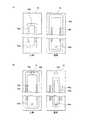
(インジェクタ18aの詳細説明)
図2(a)は、インジェクタ18aの概略斜視図である。図2(a)は、フィルムFに対向する基板対向面30を上方に向くように図示している。図2(b)は、インジェクタ18aの基板対向面30を説明する図である。(Detailed description of the
FIG. 2A is a schematic perspective view of the
基板対向面30には、複数のスリット状の開口32と、楕円形状の開口を成すガス供給ポート34,36とガス排気ポート38,40が設けられている。開口32の長さは、フィルムFの幅と同程度である。
ガス供給ポート34には、不活性ガス供給管42と接続されている。不活性ガス供給管42は、マスフローコントローラ22fを介して不活性ガス源20dと接続されている。マスフローコントローラ22fは、不活性ガスの成膜空間内への供給量を制御する。
ガス供給ポート36には、成膜用ガス供給管44と接続されている。成膜用ガス供給管44は、マスフローコントローラ22eを介して成膜用ガス源20bと接続されている。マスフローコントローラ22eは、成膜用ガスの成膜空間内への供給量を制御する。
ガス排気ポート38,40のそれぞれには、排気管46,48と接続されている。排気管46,48は、排気装置22bと接続されている。
本実施形態では、ガス供給ポート34,36とガス排気ポート38,40は、インジェクタ18aの基板対向面30に設けられているが、これに限られない。ガス供給ポート34,36とガス排気ポート38,40は、インジェクタ18aの他の面に設けられてもよい。The
The
The
The
In the present embodiment, the
基板対向面30に設けられた開口32は、図2(b)に示すように、成膜用ガス供給口50と、第1ガス排気口52,52と、不活性ガス供給口54,54と、第2ガス排気口56,56と、を含む。
成膜用ガス供給口50は、成膜用ガスを出力する開口である。第1ガス排気口52,52は、成膜用ガス供給口50に対してフィルムFの搬送方向の両側に設けられ、フィルムF上の余分なガスを吸引する開口である。不活性ガス供給口54,54は、第1ガス排気口52,52のそれぞれに対してフィルムFの搬送方向のうち成膜用ガス供給口50から遠ざかる側に設けられ、不活性なガスを出力する。As shown in FIG. 2B, the
The film forming
成膜用ガス供給口50及び不活性ガス供給口54,54の開口面には、開口の一部を塞ぐ部材50a,54aがスリット状の開口の長手方向に沿って設けられている。部材50a,54aを設けるのは、成膜用ガス供給口50及び不活性ガス供給口54,54からの成膜用ガス及び不活性ガスの噴射速度を可能な限り抑制して、フィルムFの面に穏やかに成膜用ガス及び不活性ガスを供給するためである。インジェクタイ18aの幅W(図2(b)参照)は、例えば20〜40mmであり、成膜用ガス供給口50、第1ガス排気口52,52、不活性ガス供給口54,54、及び第2ガス排気口56,56のそれぞれの開口幅は例えば1〜3mmである。
なお、本実施形態では、第2ガス排気口56,56が設けられているが、必ずしも設けられなくてもよい。しかし、不活性ガスを確実に排気し、隣接するインジェクタ18aとの間の隙間に不活性ガスが流れることにより、成膜に必要なラジカル原子やラジカル分子のフィルムFへの供給を阻害しない点で、第2ガス排気口54,54が設けられることが好ましい。On the opening surfaces of the film forming
In the present embodiment, the second
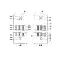
図3(a)は、インジェクタ18a内の成膜用ガスのガス流路と、不活性ガスのガス流路と、排気路を立体視して示す図であり、図3(b)は、図3(a)中のX−X’線に沿ったインジェクタ18aの断面図である。
図3(a)に示すように、インジェクタ18aの内部において、成膜用ガス供給管44と接続したガス供給ポート36から延びる管状の成膜用連続孔が設けられる。この成膜用連続孔は、インジェクタ18aの高さ方向Hに沿って上昇する上昇部60aと、上昇部60aと接続されて、インジェクタ18a内部でインジェクタ18aの幅方向Lに延びる細長い空間を形成する収容部60bと、収容部60bから成膜用ガス供給口50に向けて、高さ方向Hに沿って下降する下降部60c(図3(b)参照)と、を有する。高さ方向Hとは、インジェクタ18aのインジェクタ部材のフィルムFに対向する基板対向面30に対して垂直方向をいう。FIG. 3A is a diagram showing a three-dimensional view of the gas flow path of the film forming gas, the gas flow path of the inert gas, and the exhaust path in the
As shown in FIG. 3A, a tubular film-forming continuous hole extending from the
また、インジェクタ18aの内部において、排気管46と接続した排気ポート38から延びる排気用連続孔が設けられる。この排気用連続孔は、インジェクタ18aの高さ方向Hに沿って上昇する上昇部62aと、上昇部62aと接続されて、インジェクタ18a内部で環状を成す環状部62bと、環状部62bから排気口52に向けて、高さ方向Hに沿って下降する下降部62c(図3(b)参照)と、を有する。
さらに、インジェクタ18aの内部において、不活性ガス供給管42と接続したガス供給ポート34から延びる管状の不活性ガス用連続孔が設けられる。この不活性ガス用連続孔は、インジェクタ18aの高さ方向Hに沿って上昇する上昇部64aと、上昇部64aと接続されて、インジェクタ18a内部の上部で環状を成す環状部64bと、環状部64bから不活性ガス供給口54,54に向けて、高さ方向Hに沿って下降する下降部64c(図3(b)参照)と、を有する。Further, an exhaust continuous hole extending from the
Furthermore, a tubular inert gas continuous hole extending from the
また、インジェクタ18aの内部において、排気管48と接続した排気ポート40から延びる排気用連続孔が設けられる。この排気用連続孔は、インジェクタ18aの高さ方向Hに沿って上昇する上昇部66aと、上昇部66aと接続されて、インジェクタ18a内部で環状を成す環状部66bと、環状部66bから排気口56に向けて、高さ方向Hに沿って下降する下降部66c(図3(b)参照)と、を有する。
図3(b)に示すように、環状部62b,64b,66b及び収容部60bは、高さ方向Hの異なる位置に設けられている。Further, an exhaust continuous hole extending from the
As shown in FIG. 3B, the
このような複雑に構成される複数の連続孔を、1つの部材の内部を繰り抜いて作製することは難しい。このため、図3(b)に示すように、分割線A〜Eに沿って、環状部や収容部の位置で分割した構成にすることが好ましい。以降、インジェクタ18aのインジェクタ部材を構成する部材要素を上部から順に部材要素70,72,74,76,80とする。 It is difficult to produce a plurality of continuous holes having such a complicated structure by drawing out the inside of one member. For this reason, as shown in FIG.3 (b), it is preferable to set it as the structure divided | segmented in the position of the cyclic | annular part and the accommodating part along the dividing lines AE. Hereinafter, the member elements constituting the injector member of the
図4(a)は、最上層の部材要素70の上面図及び底面図を示し、図4(b)は、部材要素70の斜視図である。図5(a)は、最上層から2番目の部材要素72の上面図及び底面図を示し、図5(b)は、最上層から3番目の部材要素74の上面図及び底面図を示し、図6(a)は、最上層から4番目の部材要素76の上面図及び底面図を示し、図6(b)は、最上層から5番目の部材要素78の上面図及び底面図を示し、図7は、最下層の部材要素80の上面図及び底面図を示す。
部材要素70〜80は、接着剤による接着あるいは溶着により互いに接合してインジェクタ18aを構成することができる。すなわち、部材要素のそれぞれは、連続溝が設けられた部材要素が接合することにより、連続溝同士が組み合わされて、形成される。この場合、部材要素70〜80に設けられた連続溝の接続部分の周囲には必要に応じてガスケットが用いられてシールされる。
このように連続孔が複雑に設けられたインジェクタ18aであっても、部材要素の表面から部材要素毎に連続溝を掘って連続溝を形成することができるので、内部に連続孔を備えるインジェクタ18aを容易に作製することができる。FIG. 4A shows a top view and a bottom view of the
The
Even in the case of the
本実施形態のインジェクタ18aのフィルムFに対向する基板対向面30は、成膜用ガスの成膜用ガス供給口50と、成膜用ガス供給口50に対してフィルムFの搬送方向の両側に設けられ、余分な成膜用ガスを吸引する第1ガス排気口52,52と、第1ガス排気口52,52のそれぞれに対してフィルムFの搬送方向のうち成膜用ガス供給口50から遠ざかる側に設けられ、成膜成分に対して不活性なガスを供給する不活性ガス供給口54,54とを有する。すなわち、1つのインジェクタ18aにおいて成膜用ガスの供給と余分な成膜用ガスの排気(吸引)が完結するので、インジェクタ18aの幅(フィルムFの搬送方向の長さ)を短くすることができ、フィルムFの搬送速度が一定の条件では、成膜の単位時間当たりの処理量を向上させることができる。
第1ガス排気口52のそれぞれに対して成膜用ガス供給口50から遠ざかる側に不活性ガス供給口54,54が設けられるので、不活性ガスが成膜用ガスと反応性ガスを分離するバリアガスとして機能し、隣り合う2つのインジェクタ18a間の隙間から反応性ガスのラジカル原子やラジカル分子と成膜用ガスが混合して反応することを防止する。さらに、不活性ガス供給口54,54のそれぞれに対して成膜用ガス供給口50から遠ざかる側に、フィルムF上の余分なガスを吸引する第2ガス排気口56,56が設けられることで、不活性ガスを第2ガス排気口56,56から確実に回収することができる。The
Since the inert
第1ガス排気口52,52及び不活性ガス供給口54,54のそれぞれに接続された管状の連続孔の一部は、インジェクタ18aの部材の内部で環状を成している。このため、第1ガス排気口52,52の排気は、開口の長さ方向の位置に依存しない均一な排気能力を有する。また、不活性ガス供給口54,54からの不活性ガスの供給量は、開口の長さ方向の位置に依存しない均一な供給能力を有する。したがって、フィルムFに成膜用ガスの成膜成分を均一に吸着させることができる。 Part of the tubular continuous holes connected to the first
本実施形態では、第1ガス排気口52及び不活性ガス供給口54のそれぞれに接続された管状の連続孔の環状を成す環状部は、インジェクタ18aの部材の基板対向面30からの高さ方向の異なる位置に設けられる。したがって、成膜用ガス供給口50、第1ガス排気口52,52、及び不活性ガス供給口54のそれぞれを互いに近接させて設けることができる。このため、インジェクタ18aの幅(フィルムの搬送方向の長さ)を狭くすることができる。 In the present embodiment, the annular portion of the annular continuous hole connected to each of the first
インジェクタ18aの部材は、高さ方向Hに積層された複数の部材要素70〜80によって構成され、部材要素70〜80のそれぞれには、連続孔を形成するための連続溝が設けられている。連通孔のそれぞれは、部材要素70〜80のうち2つ部材要素の連続溝が合わさることにより、形成される。したがって、複雑な配置の連続孔の構成であっても、部材要素70〜80に連続溝を設けることによって複雑な配置の連続孔を容易に構成することができる。すなわち、インジェクタのコストを抑制することができる。 The member of the
本実施形態は、不活性ガス供給口54,54のそれぞれに対してフィルムFの搬送方向のうち成膜用ガス供給口50から遠ざかる側に、フィルムF上の余分な不活性ガスを吸引する第2ガス排気口56,56が設けられる。このため、不活性ガスを第2ガス排気口56,56から確実に吸収することができる。 In the present embodiment, the extra inert gas on the film F is sucked to the side away from the film forming
本実施形態では、搬送機構14と、インジェクタユニット18と、高周波電極16aとを、内部空間内に配置する成膜容器12を有し、反応物質は、成膜容器24内で高周波電極16aを用いて形成されたプラズマから生成されるラジカル原子あるいはラジカル分子を含む。このため、100℃以下の空間の温度において、フィルムF上で反応を容易に起こさせることができ、効率よく成膜を行うことができる。 In the present embodiment, the
以上、本発明のインジェクタ及び成膜装置について詳細に説明したが、本発明のインジェクタ及び成膜装置は上記実施形態に限定されず、本発明の主旨を逸脱しない範囲において、種々の改良や変更をしてもよいのはもちろんである。 As described above, the injector and the film forming apparatus of the present invention have been described in detail. Of course.
10 成膜装置
12 成膜容器
14 搬送機構
14a,14b 回転ローラ
16 プラズマ生成ユニット
16a 高周波電極
16b 接地電極
16c マッチングボックス
16d 高周波電源
16e 絶縁体
16f 絶縁体板
17 空間仕切り壁
18 インジェクタユニット
18a インジェクタ
18b ダミーインジェクタ
20 ガス供給ユニット
20a 反応性ガス源
20b 成膜用ガス源
20c パージガス源
20d 不活性ガス源
22 排気ユニット
22a,22b 排気装置
24 加熱ヒータ
30 基板対向面
32 開口
34,36 ガス供給ポート
38,40 ガス排気ポート
42 不活性ガス供給管
44 成膜用ガス供給管
46,48 排気管
50 成膜用ガス供給口
50a,54a 部材
52 第1ガス排気口
54 不活性ガス供給口
56 第2ガス排気口
60a,62a,64a,66a 上昇部
60b 収容部
60c,62c,64c,66c 下降部
62b,64b,66b 環状部
DESCRIPTION OF
Claims (10)
Translated fromJapanese基板の成膜中、前記基板を搬送する搬送機構と、
搬送中の前記基板に成膜用ガスの成膜成分の層を形成するために前記成膜用ガスを前記基板に向けて供給するインジェクタが前記基板の搬送経路に沿って複数設けられたインジェクタユニットと、
前記成膜成分と反応する反応物質を生成する反応物質供給ユニットと、を備え、
前記インジェクタユニットは、前記インジェクタの間のそれぞれの隙間から前記反応物質を前記基板に向けて供給するように構成され、
前記インジェクタのそれぞれの前記基板に対向する基板対向面は、前記成膜用ガスを出力する成膜用ガス供給口と、前記成膜用ガス供給口に対して前記基板の搬送方向の両側に設けられ、前記基板上の余分なガスを吸引する第1ガス排気口と、前記第1ガス排気口のそれぞれに対して前記搬送方向のうち前記成膜用ガス供給口から遠ざかる側に設けられ、不活性なガスを出力する不活性ガス供給口と、を備えることを特徴とする成膜装置。A film forming apparatus for forming a thin film on a substrate in units of atomic layers,
A transport mechanism for transporting the substrate during film formation of the substrate;
Injector unit injector for supplying the deposition gas toward the substrateis provided with a plurality along the transport path of the substrate to form a layer of film-forming component of the film forming gas to the substrate being transported When,
A reactant supply unit that generates a reactant that reacts with the film-forming component, and
The injector unit is configured to supply the reactants from the gaps between the injectors toward the substrate;
A substrate facing surface of each of the injectors facing the substrate is provided on both sides of the substrate transport direction with respect to the film forming gas supply port for outputting the film forming gas and the film forming gas supply port. A first gas exhaust port for sucking excess gas on the substrate, and a first gas exhaust port on the side away from the film forming gas supply port in the transport direction with respect to each of the first gas exhaust ports. And an inert gas supply port for outputting an active gas.
前記連続孔のそれぞれは、前記インジェクタ部材の面に開口を備え、前記開口において、成膜用ガス源と接続された成膜用ガス供給管、排気装置と接続された排気管、および、不活性ガス源のいずれか1つと接続された不活性ガス供給管と接続され、
前記第1ガス排気口及び前記不活性ガス供給口のそれぞれに接続された管状の連続孔の一部は、前記インジェクタ部材の内部で環状を成している、請求項1に記載の成膜装置。Each of the injectors has a tubular continuous hole connected to each of the film forming gas supply port, the first gas exhaust port, and the inert gas supply port inside an injector member constituting each of the injectors. Is provided,
Each of the continuous holes has an opening in the surface of the injector member, and in the opening, a film forming gas supply pipe connected to a film forming gas source, an exhaust pipe connected to an exhaust device, and an inert gas Connected to an inert gas supply pipe connected to any one of the gas sources;
Said portion of the first gas outlet and the inert gas supply port connected to a respective tubular continuous holes, said forms an annular inside the injector member film forming apparatus according to claim1 .
前記連続孔のうち前記環状を成している部分は、前記インジェクタ部材の前記高さ方向の異なる位置に設けられる、請求項2に記載の成膜装置。When the vertical direction with respect to the substrate facing surface of the injector member is the height direction,
The film-forming apparatus according to claim 2, wherein the annular portion of the continuous hole is provided at a different position in the height direction of the injector member.
前記インジェクタ部材は、前記高さ方向に積層された複数の部材要素によって構成され、
前記部材要素のそれぞれは、前記連続孔を形成するための連続溝が設けられ、
前記連続孔のそれぞれは、前記連続溝が設けられた前記部材要素が接合することにより、形成される、請求項2または3に記載の成膜装置。When the vertical direction with respect to the substrate facing surface of the injector member is the height direction,
The injector member is constituted by a plurality of member elements stacked in the height direction,
Each of the member elements is provided with a continuous groove for forming the continuous hole,
Each of the said continuous holes is a film-forming apparatus of Claim 2 or 3 formed when the said member element provided with the said continuous groove | channel is joined.
前記反応物質は、前記成膜容器内で前記高周波電極を用いて形成されたプラズマから生成されるラジカル原子あるいはラジカル分子を含む、請求項1〜5のいずれか1項に記載の成膜装置。Further, the transport mechanism, the injector unit, and a film forming container for arranging the high frequency electrode in the internal space,
The film forming apparatus according to claim 1, wherein the reactant includes a radical atom or a radical molecule generated from plasma formed using the high-frequency electrode in the film forming container.
前記インジェクタの前記基板に対向する基板対向面は、前記成膜用ガスの成膜用ガス供給口と、前記成膜用ガス供給口に対して前記基板の搬送方向の両側に設けられ、前記基板上の余分なガスを吸引する第1ガス排気口と、前記第1ガス排気口のそれぞれに対して前記搬送方向のうち前記成膜用ガス供給口から遠ざかる側に設けられ、前記成膜用ガスの成膜成分に対して不活性なガスを供給する不活性ガス供給口と、を備え、
前記インジェクタは、インジェクタ部材により構成され、前記インジェクタ部材の内部に、前記成膜用ガス供給口、前記第1ガス排気口、及び前記不活性ガス供給口のそれぞれに接続された管状の連続孔が設けられ、
前記連続孔のそれぞれは、前記インジェクタ部材の面に開口を備え、前記開口において、成膜用ガス源と接続された成膜用ガス供給管、排気装置と接続された排気管、および、不活性ガス源と接続された不活性ガス供給管のいずれか1つと接続され、
前記第1ガス排気口及び前記不活性ガス供給口のそれぞれに接続された管状の連続孔の一部は、前記インジェクタ部材の内部で環状を成している、ことを特徴とするインジェクタ。An injector for supplying afilm forminggas used in a film forming apparatus to a substrate,
A substrate facing surface of the injector that faces the substrate is provided on a film forming gas supply port of the film forming gas and on both sides of the film forming gas supply port on the substrate transport direction. a first gas outlet for sucking excess gas above the provided among the conveyance direction on the side away from the deposition gas supply ports for each of the first gas exhaust port, thedeposition gas An inert gas supply port for supplying an inert gas tothe film-forming component of
The injector is constituted by an injector member, and tubular continuous holes connected to the film forming gas supply port, the first gas exhaust port, and the inert gas supply port are provided inside the injector member. Provided,
Each of the continuous holes has an opening in the surface of the injector member, and in the opening, a film forming gas supply pipe connected to a film forming gas source, an exhaust pipe connected to an exhaust device, and an inert gas Connected to any one of the inert gas supply pipes connected to the gas source;
A part of the tubular continuous hole connected to each of the first gas exhaust port and the inert gas supply port forms an annular shape inside the injector member .
前記連続孔のうち前記環状を成している部分は、前記インジェクタ部材の前記基板対向面からの高さ方向の異なる位置に設けられる、請求項7に記載のインジェクタ。When the vertical direction with respect to the substrate facing surface of the injector member is the height direction,
8. The injector according to claim7 , wherein the annular portion of the continuous hole is provided at a different position in the height direction from the substrate facing surface of the injector member.
前記インジェクタ部材は、前記高さ方向に積層された複数の部材要素によって構成され、
前記部材要素のそれぞれは、前記連続孔を形成するための連続溝が設けられ、
前記連続孔のそれぞれは、前記連続溝が設けられた前記部材要素が接合することにより形成される、請求項7または8に記載のインジェクタ。When the vertical direction with respect to the substrate facing surface of the injector member is the height direction,
The injector member is constituted by a plurality of member elements stacked in the height direction,
Each of the member elements is provided with a continuous groove for forming the continuous hole,
Each of the said continuous holes is an injector of Claim7 or 8 formed when the said member element provided with the said continuous groove | channel is joined.
Priority Applications (5)
| Application Number | Priority Date | Filing Date | Title |
|---|---|---|---|
| JP2013039728AJP5432396B1 (en) | 2013-02-28 | 2013-02-28 | Film forming apparatus and injector |
| KR1020157020362AKR101669127B1 (en) | 2013-02-28 | 2014-02-21 | Layer-forming device and injector |
| EP14757718.3AEP2963151B1 (en) | 2013-02-28 | 2014-02-21 | Film-forming device and injector |
| US14/770,793US10669630B2 (en) | 2013-02-28 | 2014-02-21 | Layer-forming device and injector |
| PCT/JP2014/054177WO2014132892A1 (en) | 2013-02-28 | 2014-02-21 | Film-forming device and injector |
Applications Claiming Priority (1)
| Application Number | Priority Date | Filing Date | Title |
|---|---|---|---|
| JP2013039728AJP5432396B1 (en) | 2013-02-28 | 2013-02-28 | Film forming apparatus and injector |
Publications (2)
| Publication Number | Publication Date |
|---|---|
| JP5432396B1true JP5432396B1 (en) | 2014-03-05 |
| JP2014167153A JP2014167153A (en) | 2014-09-11 |
Family
ID=50396565
Family Applications (1)
| Application Number | Title | Priority Date | Filing Date |
|---|---|---|---|
| JP2013039728AActiveJP5432396B1 (en) | 2013-02-28 | 2013-02-28 | Film forming apparatus and injector |
Country Status (5)
| Country | Link |
|---|---|
| US (1) | US10669630B2 (en) |
| EP (1) | EP2963151B1 (en) |
| JP (1) | JP5432396B1 (en) |
| KR (1) | KR101669127B1 (en) |
| WO (1) | WO2014132892A1 (en) |
Cited By (5)
| Publication number | Priority date | Publication date | Assignee | Title |
|---|---|---|---|---|
| JP2016040825A (en)* | 2014-08-12 | 2016-03-24 | ラム リサーチ コーポレーションLam Research Corporation | Differentially pumped reactive gas injector |
| US10825652B2 (en) | 2014-08-29 | 2020-11-03 | Lam Research Corporation | Ion beam etch without need for wafer tilt or rotation |
| US11062920B2 (en) | 2014-08-29 | 2021-07-13 | Lam Research Corporation | Ion injector and lens system for ion beam milling |
| US11289306B2 (en) | 2016-02-25 | 2022-03-29 | Lam Research Corporation | Ion beam etching utilizing cryogenic wafer temperatures |
| US12029133B2 (en) | 2019-02-28 | 2024-07-02 | Lam Research Corporation | Ion beam etching with sidewall cleaning |
Families Citing this family (7)
| Publication number | Priority date | Publication date | Assignee | Title |
|---|---|---|---|---|
| US10167552B2 (en)* | 2015-02-05 | 2019-01-01 | Lam Research Ag | Spin chuck with rotating gas showerhead |
| CN108291303B (en)* | 2015-12-17 | 2020-07-21 | 倍耐克有限公司 | Coating Precursor Nozzles and Nozzle Tips |
| JP6608332B2 (en)* | 2016-05-23 | 2019-11-20 | 東京エレクトロン株式会社 | Deposition equipment |
| US11251019B2 (en)* | 2016-12-15 | 2022-02-15 | Toyota Jidosha Kabushiki Kaisha | Plasma device |
| JP6640781B2 (en)* | 2017-03-23 | 2020-02-05 | キオクシア株式会社 | Semiconductor manufacturing equipment |
| JP6863199B2 (en) | 2017-09-25 | 2021-04-21 | トヨタ自動車株式会社 | Plasma processing equipment |
| JP7378276B2 (en)* | 2019-11-12 | 2023-11-13 | 東京エレクトロン株式会社 | plasma processing equipment |
Family Cites Families (12)
| Publication number | Priority date | Publication date | Assignee | Title |
|---|---|---|---|---|
| JPH02166735A (en) | 1988-12-21 | 1990-06-27 | Nec Corp | Atmospheric pressure cvd apparatus |
| US6926920B2 (en)* | 2002-06-11 | 2005-08-09 | Taiwan Semiconductor Manufacturing Co., Ltd | Chemical vapor deposition (CVD) calibration method providing enhanced uniformity |
| JP3941066B2 (en) | 2003-09-11 | 2007-07-04 | 俊次 村野 | Line-shaped uniform discharge device, atomizing device, thin film forming device, pattern forming device, three-dimensional modeling device and cleaning device. |
| JP2007324529A (en) | 2006-06-05 | 2007-12-13 | Tokyo Electron Ltd | Gas inlet apparatus, manufacturing method therefor, and processing apparatus |
| JP5092624B2 (en)* | 2007-08-24 | 2012-12-05 | 大日本印刷株式会社 | Method and apparatus for producing gas barrier film |
| US8017183B2 (en) | 2007-09-26 | 2011-09-13 | Eastman Kodak Company | Organosiloxane materials for selective area deposition of inorganic materials |
| US8333839B2 (en)* | 2007-12-27 | 2012-12-18 | Synos Technology, Inc. | Vapor deposition reactor |
| JP2010192197A (en) | 2009-02-17 | 2010-09-02 | Tokyo Electron Ltd | Substrate processing apparatus, and substrate processing method |
| US20110097491A1 (en)* | 2009-10-27 | 2011-04-28 | Levy David H | Conveyance system including opposed fluid distribution manifolds |
| US20120237695A1 (en) | 2009-12-23 | 2012-09-20 | 2-Pye Solar, LLC | Method and apparatus for depositing a thin film |
| FI20105909A0 (en) | 2010-08-30 | 2010-08-30 | Beneq Oy | spray head |
| JP5369304B2 (en) | 2010-09-30 | 2013-12-18 | ソイテック | System and method for forming semiconductor material by atomic layer deposition |
- 2013
- 2013-02-28JPJP2013039728Apatent/JP5432396B1/enactiveActive
- 2014
- 2014-02-21WOPCT/JP2014/054177patent/WO2014132892A1/enactiveApplication Filing
- 2014-02-21USUS14/770,793patent/US10669630B2/ennot_activeExpired - Fee Related
- 2014-02-21KRKR1020157020362Apatent/KR101669127B1/enactiveActive
- 2014-02-21EPEP14757718.3Apatent/EP2963151B1/enactiveActive
Cited By (8)
| Publication number | Priority date | Publication date | Assignee | Title |
|---|---|---|---|---|
| JP2016040825A (en)* | 2014-08-12 | 2016-03-24 | ラム リサーチ コーポレーションLam Research Corporation | Differentially pumped reactive gas injector |
| US10580628B2 (en) | 2014-08-12 | 2020-03-03 | Lam Research Corporation | Differentially pumped reactive gas injector |
| US10825652B2 (en) | 2014-08-29 | 2020-11-03 | Lam Research Corporation | Ion beam etch without need for wafer tilt or rotation |
| US10998167B2 (en) | 2014-08-29 | 2021-05-04 | Lam Research Corporation | Ion beam etch without need for wafer tilt or rotation |
| US11062920B2 (en) | 2014-08-29 | 2021-07-13 | Lam Research Corporation | Ion injector and lens system for ion beam milling |
| US11289306B2 (en) | 2016-02-25 | 2022-03-29 | Lam Research Corporation | Ion beam etching utilizing cryogenic wafer temperatures |
| US12029133B2 (en) | 2019-02-28 | 2024-07-02 | Lam Research Corporation | Ion beam etching with sidewall cleaning |
| US12302760B2 (en) | 2019-02-28 | 2025-05-13 | Lam Research Corporation | Ion beam etching with sidewall cleaning |
Also Published As
| Publication number | Publication date |
|---|---|
| KR101669127B1 (en) | 2016-10-25 |
| WO2014132892A1 (en) | 2014-09-04 |
| US20160010209A1 (en) | 2016-01-14 |
| JP2014167153A (en) | 2014-09-11 |
| EP2963151A1 (en) | 2016-01-06 |
| EP2963151A4 (en) | 2017-03-08 |
| KR20150103143A (en) | 2015-09-09 |
| EP2963151B1 (en) | 2019-08-21 |
| US10669630B2 (en) | 2020-06-02 |
Similar Documents
| Publication | Publication Date | Title |
|---|---|---|
| JP5432396B1 (en) | Film forming apparatus and injector | |
| KR101324367B1 (en) | Film deposition apparatus, film deposition method, and computer-readable storage medium | |
| TWI494464B (en) | Film deposition apparatus | |
| CN101660138B (en) | Activated gas injection device, film forming device and film forming method | |
| JP5674794B2 (en) | Deposition reactor for forming a thin film on a curved surface | |
| JP5444228B2 (en) | Method for depositing thin film material on a substrate | |
| TWI465602B (en) | Film deposition apparatus, film deposition method, and computer readable storage medium | |
| JP5392069B2 (en) | Deposition equipment | |
| JP2010541236A (en) | Method and deposition apparatus for thin film formation using a gas delivery head that spatially separates reactive gases and with movement of a substrate through the delivery head | |
| KR20130079489A (en) | Rotating reactor assembly for depositing film on substrate | |
| KR102595355B1 (en) | Deposition apparatus and depositon method using the same | |
| WO2019019569A1 (en) | Spray head, apparatus, and corresponding method for film coating | |
| JP5432395B1 (en) | Film forming apparatus and film forming method | |
| US20140206137A1 (en) | Deposition system for thin film formation | |
| JP2018048395A (en) | Vapor deposition apparatus and vapor deposition method for composite membrane | |
| KR102808629B1 (en) | Gas supply unit and substrate processing apparatus including gas supply unit | |
| JP6139947B2 (en) | Film forming apparatus and film forming method | |
| JP5901554B2 (en) | Film forming apparatus and film forming method | |
| CN105018901B (en) | Film deposition apparatus | |
| JP2017218611A (en) | Film forming apparatus and film forming method |
Legal Events
| Date | Code | Title | Description |
|---|---|---|---|
| TRDD | Decision of grant or rejection written | ||
| A01 | Written decision to grant a patent or to grant a registration (utility model) | Free format text:JAPANESE INTERMEDIATE CODE: A01 Effective date:20131105 | |
| A61 | First payment of annual fees (during grant procedure) | Free format text:JAPANESE INTERMEDIATE CODE: A61 Effective date:20131205 | |
| R150 | Certificate of patent or registration of utility model | Ref document number:5432396 Country of ref document:JP Free format text:JAPANESE INTERMEDIATE CODE: R150 Free format text:JAPANESE INTERMEDIATE CODE: R150 | |
| S111 | Request for change of ownership or part of ownership | Free format text:JAPANESE INTERMEDIATE CODE: R313111 | |
| S533 | Written request for registration of change of name | Free format text:JAPANESE INTERMEDIATE CODE: R313533 | |
| R350 | Written notification of registration of transfer | Free format text:JAPANESE INTERMEDIATE CODE: R350 | |
| R250 | Receipt of annual fees | Free format text:JAPANESE INTERMEDIATE CODE: R250 | |
| S111 | Request for change of ownership or part of ownership | Free format text:JAPANESE INTERMEDIATE CODE: R313111 | |
| R350 | Written notification of registration of transfer | Free format text:JAPANESE INTERMEDIATE CODE: R350 | |
| R250 | Receipt of annual fees | Free format text:JAPANESE INTERMEDIATE CODE: R250 | |
| R250 | Receipt of annual fees | Free format text:JAPANESE INTERMEDIATE CODE: R250 |