JP5431971B2 - End-breathing gas estimation system and method - Google Patents
End-breathing gas estimation system and methodDownload PDFInfo
- Publication number
- JP5431971B2 JP5431971B2JP2009553787AJP2009553787AJP5431971B2JP 5431971 B2JP5431971 B2JP 5431971B2JP 2009553787 AJP2009553787 AJP 2009553787AJP 2009553787 AJP2009553787 AJP 2009553787AJP 5431971 B2JP5431971 B2JP 5431971B2
- Authority
- JP
- Japan
- Prior art keywords
- gas
- respiratory gas
- ventilation
- values
- tidal
- Prior art date
- Legal status (The legal status is an assumption and is not a legal conclusion. Google has not performed a legal analysis and makes no representation as to the accuracy of the status listed.)
- Expired - Fee Related
Links
- 238000000034methodMethods0.000titleclaimsdescription38
- 239000007789gasSubstances0.000claimsdescription135
- CURLTUGMZLYLDI-UHFFFAOYSA-NCarbon dioxideChemical compoundO=C=OCURLTUGMZLYLDI-UHFFFAOYSA-N0.000claimsdescription60
- 238000009423ventilationMethods0.000claimsdescription50
- 230000000241respiratory effectEffects0.000claimsdescription39
- 229910002092carbon dioxideInorganic materials0.000claimsdescription30
- 230000029058respiratory gaseous exchangeEffects0.000claimsdescription30
- 239000001569carbon dioxideSubstances0.000claimsdescription29
- QVGXLLKOCUKJST-UHFFFAOYSA-Natomic oxygenChemical compound[O]QVGXLLKOCUKJST-UHFFFAOYSA-N0.000claimsdescription12
- 229910052760oxygenInorganic materials0.000claimsdescription12
- 239000001301oxygenSubstances0.000claimsdescription12
- 210000001367arteryAnatomy0.000claimsdescription11
- MWUXSHHQAYIFBG-UHFFFAOYSA-NNitric oxideChemical compoundO=[N]MWUXSHHQAYIFBG-UHFFFAOYSA-N0.000claimsdescription8
- GQPLMRYTRLFLPF-UHFFFAOYSA-NNitrous OxideChemical compound[O-][N+]#NGQPLMRYTRLFLPF-UHFFFAOYSA-N0.000claimsdescription8
- 239000001272nitrous oxideSubstances0.000claimsdescription4
- 230000003444anaesthetic effectEffects0.000claims3
- 238000005259measurementMethods0.000description37
- 230000036961partial effectEffects0.000description12
- 238000001361intraarterial administrationMethods0.000description10
- 238000013459approachMethods0.000description7
- 238000005070samplingMethods0.000description7
- 230000008859changeEffects0.000description6
- 238000012545processingMethods0.000description6
- 230000005855radiationEffects0.000description6
- 238000003860storageMethods0.000description6
- 210000004072lungAnatomy0.000description5
- 230000007704transitionEffects0.000description5
- 230000003434inspiratory effectEffects0.000description4
- 230000002685pulmonary effectEffects0.000description4
- 239000008280bloodSubstances0.000description3
- 210000004369bloodAnatomy0.000description3
- 230000000694effectsEffects0.000description3
- 238000011156evaluationMethods0.000description3
- 238000012417linear regressionMethods0.000description3
- 238000000691measurement methodMethods0.000description3
- 238000004088simulationMethods0.000description3
- 238000004458analytical methodMethods0.000description2
- 238000013528artificial neural networkMethods0.000description2
- 230000000712assemblyEffects0.000description2
- 238000000429assemblyMethods0.000description2
- 230000017531blood circulationEffects0.000description2
- 238000010241blood samplingMethods0.000description2
- 230000008822capillary blood flowEffects0.000description2
- 230000000875corresponding effectEffects0.000description2
- 238000010586diagramMethods0.000description2
- 208000037265diseases, disorders, signs and symptomsDiseases0.000description2
- 238000007620mathematical functionMethods0.000description2
- 238000005399mechanical ventilationMethods0.000description2
- 230000004048modificationEffects0.000description2
- 238000012986modificationMethods0.000description2
- 238000012544monitoring processMethods0.000description2
- 230000008569processEffects0.000description2
- 230000000630rising effectEffects0.000description2
- 230000032258transportEffects0.000description2
- 241000722946Acanthocybium solandriSpecies0.000description1
- OKTJSMMVPCPJKN-UHFFFAOYSA-NCarbonChemical compound[C]OKTJSMMVPCPJKN-UHFFFAOYSA-N0.000description1
- 206010021133HypoventilationDiseases0.000description1
- 238000001069Raman spectroscopyMethods0.000description1
- 208000027418Wounds and injuryDiseases0.000description1
- 230000005856abnormalityEffects0.000description1
- 238000010521absorption reactionMethods0.000description1
- 230000002411adverseEffects0.000description1
- 210000003484anatomyAnatomy0.000description1
- 229940035674anestheticsDrugs0.000description1
- 229910052799carbonInorganic materials0.000description1
- 230000002612cardiopulmonary effectEffects0.000description1
- 230000008094contradictory effectEffects0.000description1
- 230000002596correlated effectEffects0.000description1
- 230000006378damageEffects0.000description1
- 230000003247decreasing effectEffects0.000description1
- 238000010790dilutionMethods0.000description1
- 239000012895dilutionSubstances0.000description1
- 201000010099diseaseDiseases0.000description1
- 238000009826distributionMethods0.000description1
- 230000029142excretionEffects0.000description1
- 239000003193general anesthetic agentSubstances0.000description1
- 230000002068genetic effectEffects0.000description1
- 208000000122hyperventilationDiseases0.000description1
- 230000000870hyperventilationEffects0.000description1
- 208000014674injuryDiseases0.000description1
- 210000005246left atriumAnatomy0.000description1
- 238000004519manufacturing processMethods0.000description1
- 238000004949mass spectrometryMethods0.000description1
- 230000003287optical effectEffects0.000description1
- 230000000737periodic effectEffects0.000description1
- 230000035790physiological processes and functionsEffects0.000description1
- 230000002035prolonged effectEffects0.000description1
- 230000002829reductive effectEffects0.000description1
- 230000036391respiratory frequencyEffects0.000description1
- 238000006467substitution reactionMethods0.000description1
- 238000012384transportation and deliveryMethods0.000description1
- 230000003519ventilatory effectEffects0.000description1
Images


Classifications
- A—HUMAN NECESSITIES
- A61—MEDICAL OR VETERINARY SCIENCE; HYGIENE
- A61B—DIAGNOSIS; SURGERY; IDENTIFICATION
- A61B5/00—Measuring for diagnostic purposes; Identification of persons
- A61B5/08—Measuring devices for evaluating the respiratory organs
- A61B5/083—Measuring rate of metabolism by using breath test, e.g. measuring rate of oxygen consumption
- A61B5/0836—Measuring rate of CO2 production
- A—HUMAN NECESSITIES
- A61—MEDICAL OR VETERINARY SCIENCE; HYGIENE
- A61B—DIAGNOSIS; SURGERY; IDENTIFICATION
- A61B5/00—Measuring for diagnostic purposes; Identification of persons
- A61B5/08—Measuring devices for evaluating the respiratory organs
- A61B5/087—Measuring breath flow
- A—HUMAN NECESSITIES
- A61—MEDICAL OR VETERINARY SCIENCE; HYGIENE
- A61M—DEVICES FOR INTRODUCING MEDIA INTO, OR ONTO, THE BODY; DEVICES FOR TRANSDUCING BODY MEDIA OR FOR TAKING MEDIA FROM THE BODY; DEVICES FOR PRODUCING OR ENDING SLEEP OR STUPOR
- A61M16/00—Devices for influencing the respiratory system of patients by gas treatment, e.g. ventilators; Tracheal tubes
- A61M16/021—Devices for influencing the respiratory system of patients by gas treatment, e.g. ventilators; Tracheal tubes operated by electrical means
- A61M16/022—Control means therefor
- A61M16/024—Control means therefor including calculation means, e.g. using a processor
- A61M16/026—Control means therefor including calculation means, e.g. using a processor specially adapted for predicting, e.g. for determining an information representative of a flow limitation during a ventilation cycle by using a root square technique or a regression analysis
- A—HUMAN NECESSITIES
- A61—MEDICAL OR VETERINARY SCIENCE; HYGIENE
- A61M—DEVICES FOR INTRODUCING MEDIA INTO, OR ONTO, THE BODY; DEVICES FOR TRANSDUCING BODY MEDIA OR FOR TAKING MEDIA FROM THE BODY; DEVICES FOR PRODUCING OR ENDING SLEEP OR STUPOR
- A61M16/00—Devices for influencing the respiratory system of patients by gas treatment, e.g. ventilators; Tracheal tubes
- A61M16/10—Preparation of respiratory gases or vapours
- A61M16/14—Preparation of respiratory gases or vapours by mixing different fluids, one of them being in a liquid phase
- A61M16/16—Devices to humidify the respiration air
- A61M16/161—Devices to humidify the respiration air with means for measuring the humidity
- A—HUMAN NECESSITIES
- A61—MEDICAL OR VETERINARY SCIENCE; HYGIENE
- A61M—DEVICES FOR INTRODUCING MEDIA INTO, OR ONTO, THE BODY; DEVICES FOR TRANSDUCING BODY MEDIA OR FOR TAKING MEDIA FROM THE BODY; DEVICES FOR PRODUCING OR ENDING SLEEP OR STUPOR
- A61M16/00—Devices for influencing the respiratory system of patients by gas treatment, e.g. ventilators; Tracheal tubes
- A61M16/0003—Accessories therefor, e.g. sensors, vibrators, negative pressure
- A61M2016/0027—Accessories therefor, e.g. sensors, vibrators, negative pressure pressure meter
- A—HUMAN NECESSITIES
- A61—MEDICAL OR VETERINARY SCIENCE; HYGIENE
- A61M—DEVICES FOR INTRODUCING MEDIA INTO, OR ONTO, THE BODY; DEVICES FOR TRANSDUCING BODY MEDIA OR FOR TAKING MEDIA FROM THE BODY; DEVICES FOR PRODUCING OR ENDING SLEEP OR STUPOR
- A61M16/00—Devices for influencing the respiratory system of patients by gas treatment, e.g. ventilators; Tracheal tubes
- A61M16/0003—Accessories therefor, e.g. sensors, vibrators, negative pressure
- A61M2016/003—Accessories therefor, e.g. sensors, vibrators, negative pressure with a flowmeter
- A61M2016/0033—Accessories therefor, e.g. sensors, vibrators, negative pressure with a flowmeter electrical
- A61M2016/0036—Accessories therefor, e.g. sensors, vibrators, negative pressure with a flowmeter electrical in the breathing tube and used in both inspiratory and expiratory phase
- A—HUMAN NECESSITIES
- A61—MEDICAL OR VETERINARY SCIENCE; HYGIENE
- A61M—DEVICES FOR INTRODUCING MEDIA INTO, OR ONTO, THE BODY; DEVICES FOR TRANSDUCING BODY MEDIA OR FOR TAKING MEDIA FROM THE BODY; DEVICES FOR PRODUCING OR ENDING SLEEP OR STUPOR
- A61M2202/00—Special media to be introduced, removed or treated
- A61M2202/02—Gases
- A61M2202/0208—Oxygen
- A—HUMAN NECESSITIES
- A61—MEDICAL OR VETERINARY SCIENCE; HYGIENE
- A61M—DEVICES FOR INTRODUCING MEDIA INTO, OR ONTO, THE BODY; DEVICES FOR TRANSDUCING BODY MEDIA OR FOR TAKING MEDIA FROM THE BODY; DEVICES FOR PRODUCING OR ENDING SLEEP OR STUPOR
- A61M2202/00—Special media to be introduced, removed or treated
- A61M2202/02—Gases
- A61M2202/0225—Carbon oxides, e.g. Carbon dioxide
- A—HUMAN NECESSITIES
- A61—MEDICAL OR VETERINARY SCIENCE; HYGIENE
- A61M—DEVICES FOR INTRODUCING MEDIA INTO, OR ONTO, THE BODY; DEVICES FOR TRANSDUCING BODY MEDIA OR FOR TAKING MEDIA FROM THE BODY; DEVICES FOR PRODUCING OR ENDING SLEEP OR STUPOR
- A61M2202/00—Special media to be introduced, removed or treated
- A61M2202/02—Gases
- A61M2202/0241—Anaesthetics; Analgesics
- A—HUMAN NECESSITIES
- A61—MEDICAL OR VETERINARY SCIENCE; HYGIENE
- A61M—DEVICES FOR INTRODUCING MEDIA INTO, OR ONTO, THE BODY; DEVICES FOR TRANSDUCING BODY MEDIA OR FOR TAKING MEDIA FROM THE BODY; DEVICES FOR PRODUCING OR ENDING SLEEP OR STUPOR
- A61M2202/00—Special media to be introduced, removed or treated
- A61M2202/02—Gases
- A61M2202/0266—Nitrogen (N)
- A61M2202/0275—Nitric oxide [NO]
- A—HUMAN NECESSITIES
- A61—MEDICAL OR VETERINARY SCIENCE; HYGIENE
- A61M—DEVICES FOR INTRODUCING MEDIA INTO, OR ONTO, THE BODY; DEVICES FOR TRANSDUCING BODY MEDIA OR FOR TAKING MEDIA FROM THE BODY; DEVICES FOR PRODUCING OR ENDING SLEEP OR STUPOR
- A61M2202/00—Special media to be introduced, removed or treated
- A61M2202/02—Gases
- A61M2202/0266—Nitrogen (N)
- A61M2202/0283—Nitrous oxide (N2O)
- A—HUMAN NECESSITIES
- A61—MEDICAL OR VETERINARY SCIENCE; HYGIENE
- A61M—DEVICES FOR INTRODUCING MEDIA INTO, OR ONTO, THE BODY; DEVICES FOR TRANSDUCING BODY MEDIA OR FOR TAKING MEDIA FROM THE BODY; DEVICES FOR PRODUCING OR ENDING SLEEP OR STUPOR
- A61M2205/00—General characteristics of the apparatus
- A61M2205/50—General characteristics of the apparatus with microprocessors or computers
- A61M2205/502—User interfaces, e.g. screens or keyboards
- A—HUMAN NECESSITIES
- A61—MEDICAL OR VETERINARY SCIENCE; HYGIENE
- A61M—DEVICES FOR INTRODUCING MEDIA INTO, OR ONTO, THE BODY; DEVICES FOR TRANSDUCING BODY MEDIA OR FOR TAKING MEDIA FROM THE BODY; DEVICES FOR PRODUCING OR ENDING SLEEP OR STUPOR
- A61M2230/00—Measuring parameters of the user
- A61M2230/40—Respiratory characteristics
- A61M2230/43—Composition of exhalation
- A61M2230/432—Composition of exhalation partial CO2 pressure (P-CO2)
- A—HUMAN NECESSITIES
- A61—MEDICAL OR VETERINARY SCIENCE; HYGIENE
- A61M—DEVICES FOR INTRODUCING MEDIA INTO, OR ONTO, THE BODY; DEVICES FOR TRANSDUCING BODY MEDIA OR FOR TAKING MEDIA FROM THE BODY; DEVICES FOR PRODUCING OR ENDING SLEEP OR STUPOR
- A61M2230/00—Measuring parameters of the user
- A61M2230/40—Respiratory characteristics
- A61M2230/43—Composition of exhalation
- A61M2230/435—Composition of exhalation partial O2 pressure (P-O2)
- A—HUMAN NECESSITIES
- A61—MEDICAL OR VETERINARY SCIENCE; HYGIENE
- A61M—DEVICES FOR INTRODUCING MEDIA INTO, OR ONTO, THE BODY; DEVICES FOR TRANSDUCING BODY MEDIA OR FOR TAKING MEDIA FROM THE BODY; DEVICES FOR PRODUCING OR ENDING SLEEP OR STUPOR
- A61M2230/00—Measuring parameters of the user
- A61M2230/40—Respiratory characteristics
- A61M2230/43—Composition of exhalation
- A61M2230/437—Composition of exhalation the anaesthetic agent concentration
Landscapes
- Health & Medical Sciences (AREA)
- Life Sciences & Earth Sciences (AREA)
- General Health & Medical Sciences (AREA)
- Public Health (AREA)
- Engineering & Computer Science (AREA)
- Biomedical Technology (AREA)
- Heart & Thoracic Surgery (AREA)
- Veterinary Medicine (AREA)
- Pulmonology (AREA)
- Animal Behavior & Ethology (AREA)
- Emergency Medicine (AREA)
- Physiology (AREA)
- Hematology (AREA)
- Anesthesiology (AREA)
- Physics & Mathematics (AREA)
- Biophysics (AREA)
- Pathology (AREA)
- Medical Informatics (AREA)
- Molecular Biology (AREA)
- Surgery (AREA)
- Obesity (AREA)
- Measurement Of The Respiration, Hearing Ability, Form, And Blood Characteristics Of Living Organisms (AREA)
- Management, Administration, Business Operations System, And Electronic Commerce (AREA)
Description
Translated fromJapanese本発明は、信頼性が高い呼吸終期の二酸化炭素(CO2)、呼吸終期の酸素(O2)又は他の気体の推定を提供するための方法及び装置に関する。The present invention relates to a method and apparatus for providing a reliable estimate of end-tidal carbon dioxide (CO2 ), end-tidal oxygen (O2 ), or other gases.
呼吸気体モニタリングシステムは、一般的に気体センシング、測定、処理、給送及び表示機能を有する。そのようなシステムは、迂回システム(すなわち副流システム)であるか、又は迂回しないシステム(すなわち主流システム)のいずれかであると考えられている。迂回気体測定システムは、一般的に呼吸回路又は患者の気道であるサンプリング位置から、サンプリングチューブを通して気体センサへと、サンプリングされた気体の一部を輸送し、そこで気体の成分が測定される。迂回しない気体測定システムは、呼吸回路又は気道から離れて気体を輸送せず、呼吸回路中を通過している気体成分を測定する。 Respiratory gas monitoring systems generally have gas sensing, measurement, processing, delivery and display functions. Such a system is considered to be either a bypass system (ie, a secondary system) or a system that does not bypass (ie, a mainstream system). A bypass gas measurement system transports a portion of the sampled gas from a sampling location, typically a breathing circuit or patient airway, through a sampling tube to a gas sensor where the component of the gas is measured. A non-bypass gas measurement system does not transport gas away from the breathing circuit or airway, but measures the gas component passing through the breathing circuit.
従来の迂回しない気体測定システムは、気体センシング、測定、及び、検出された又は測定された信号(例えば電圧)をホストシステムによって用いられることができる値に変換するために必要とされる信号処理を含む。気体測定システムは、呼吸回路に配置される試料セルと連通して、測定される気体の特性に対応する信号を出力するために必要とされるコンポーネントを有する。試料セルを呼吸回路に直接配置することで、気道内の測定される気体(例えば二酸化炭素又は酸素) の分圧をリアルタイムに反映する「はっきりとした」波形がもたらされる。試料セル(キュベット又は気道アダプタとも呼ばれる) は、呼吸気体ストリーム中に設置されて、迂回気体測定システムにおいて必要とされるような気体サンプリング及び捕集の必要性を不要にする。 Traditional non-bypass gas measurement systems perform gas sensing, measurement, and signal processing required to convert the detected or measured signal (e.g., voltage) into a value that can be used by the host system. Including. The gas measurement system has components required to communicate with a sample cell located in the breathing circuit and output signals corresponding to the characteristics of the gas being measured. Placing the sample cell directly in the breathing circuit provides a “clear” waveform that reflects in real time the partial pressure of the gas (eg, carbon dioxide or oxygen) to be measured in the airway. A sample cell (also referred to as a cuvette or airway adapter) is installed in the respiratory gas stream, eliminating the need for gas sampling and collection as required in bypass gas measurement systems.
従来の迂回気体測定システムは、呼吸回路中のアダプタ(例えば気管内チューブ又はマスクコネクタのT継手)に接続される比較的長いサンプリング用プラスチックチューブ、すなわち経鼻カテーテルを利用する。サンプル気体は、50〜250ml/minの範囲のサンプル流量で、サンプリングチューブを通して呼吸回路又はサンプル位置から、モニタの中のサンプルセルへと、連続的に吸引される。呼吸中のサンプリングポートの位置は多様であり、気管内チューブに接続されるL字継手からY字管コネクタまでのどこにでも及ぶことができる。 Conventional detour gas measurement systems utilize relatively long sampling plastic tubes or nasal catheters that are connected to adapters in the breathing circuit (eg, endotracheal tubes or mask connector T-joints). Sample gas is continuously aspirated from the breathing circuit or sample location through the sampling tube to the sample cell in the monitor at a sample flow rate in the range of 50-250 ml / min. The location of the sampling port during breathing varies and can span anywhere from the L-joint connected to the endotracheal tube to the Y-tube connector.
迂回する及び迂回しない気体測定システムの両方は、サンプルセル中を通過するサンプリングされた気体中の気体成分のうちの少なくとも一つの濃度及び/又は分圧を測定するセンサを含む。臨床的に重要な最も一般に測定される気体のうちの2つは、二酸化炭素及び酸素である。迂回する及び迂回しない気体測定システムの両方は、気体(例えば二酸化炭素及び酸素) の成分を測定するためにセンサを利用する。 Both bypassing and non-bypassing gas measurement systems include sensors that measure the concentration and / or partial pressure of at least one of the gaseous components in the sampled gas passing through the sample cell. Two of the most commonly measured gases of clinical importance are carbon dioxide and oxygen. Both bypass and non-bypass gas measurement systems utilize sensors to measure components of gases (eg, carbon dioxide and oxygen).
これらの気体を測定するために、電気光学アセンブリが、しばしば使用される。二酸化炭素センサ及び他の複数の気体センサの場合では、これらのアセンブリは、二酸化炭素の吸収バンドを持つ赤外線を放射する光源を含む。赤外線は、通常、分析されている気体ストリームの流動経路に垂直である経路に沿って透過する。気体ストリーム中の気体中を通過した透過放射線を受け取って測定するために、光検出器が配置される。サンプル気体内の二酸化炭素は、いくつかの波長でこの放射線を吸収して、他の波長を通過させる。透過放射線は信号に変換され、それからプロセッサは二酸化炭素の分圧を計算する。酸素センサの場合には、電気化学又は蛍光に基づく技術がしばしば使用される。 Electro-optic assemblies are often used to measure these gases. In the case of carbon dioxide sensors and other gas sensors, these assemblies include a light source that emits infrared radiation having a carbon dioxide absorption band. Infrared radiation is typically transmitted along a path that is perpendicular to the flow path of the gas stream being analyzed. A photodetector is arranged to receive and measure the transmitted radiation that has passed through the gas in the gas stream. Carbon dioxide in the sample gas absorbs this radiation at some wavelengths and passes other wavelengths. The transmitted radiation is converted into a signal, and then the processor calculates the partial pressure of carbon dioxide. In the case of oxygen sensors, techniques based on electrochemical or fluorescence are often used.
二酸化炭素及び酸素は、気体留分(FCO2及びFO2)又は分圧(PCO2及びPO2)として表現される。カプノグラフィ(capnography)及びオキシグラフィ(oxygraphy)は、無条件に用いられる場合、時系列カプノグラフィ及びオキシグラフィを指す。カプノメトリ(capnometry)に加えて、カプノグラフィは、呼吸サイクルの経過にわたる瞬間的な二酸化炭素濃度のプロットを含む。このプロットから、周期的な変化が視覚化されることができる。Carbon dioxide and oxygen are expressed as gas fractions (FCO2 and FO2 ) or partial pressures (PCO2 and PO2 ). Capnography and oxygraphy, when used unconditionally, refers to time-series capnography and oxygraphy. In addition to capnometry, capnography includes a plot of instantaneous carbon dioxide concentration over the course of the respiratory cycle. From this plot, periodic changes can be visualized.
一例が図1に示される教科書的なカプノグラム2において、カプノグラムは、「呼気」セグメント4及び「吸気」セグメント6の、2つのセグメントを有する。呼気セグメントは、変化する上向き勾配5aから成り、一定又はわずかな上向き勾配5bで横ばいになる。吸気セグメントは、急な下り勾配7aから成り、無視できる吸気二酸化炭素の平坦域7bに落ちつく。しかしながら、呼息の終わりの二酸化炭素の分圧として一般に理解される二酸化炭素の呼吸終期の分圧以外の、呼吸頻度及び吸気二酸化炭素レベルの測度だけが報告される。これは、呼気セグメントと吸気セグメントとの間の遷移だけが、通常、カプノグラムから正確に説明されることができるからである。 In the
その場合にも、再呼吸が実質的にない場合にだけ、この遷移は、流動波形によって詳細に描写されるような吸息の実際の開始の時刻に対応する。呼息の終わりに吸気気体によって満たされる解剖学的デッドスペースの存在のために、吸息と呼息との間の遷移は容易に識別されることができない。オキシグラム(oxygram)はカプノグラムほど臨床的に広く使用されていないが、オキシグラムがカプノグラムの反転バージョンであるとみなされることができることを理解すれば、上で論じられる同じ問題がオキシグラムにあてはまる。 Again, only if there is substantially no rebreathing, this transition corresponds to the actual start time of inspiration as detailed by the flow waveform. Because of the presence of an anatomical dead space filled with inspiratory gas at the end of exhalation, the transition between inspiration and expiration cannot be easily identified. Although oxygrams are not as widely used clinically as capnograms, the same issues discussed above apply to oxygrams if it is understood that oxygrams can be considered as inverted versions of capnograms.
二酸化炭素に加えて流動が測定される場合、体積測定カプノグラムが決定されることができる。同様に、酸素に加えて流動が測定される場合、体積測定オキシグラムが決定されることができる。図2は、体積測定カプノグラムの3つのフェーズを示す。フェーズIは、二酸化炭素のないボリュームから成り、フェーズIIは、肺胞を徐々に空にすることから生じる急速に上昇する二酸化炭素濃度によって特徴づけられる遷移領域から成る。フェーズII及びIIIは共に、呼吸(有効一回呼吸量Vteff)の二酸化炭素含有部分である。フェーズIII (肺胞平坦域) は、一般的に、上昇するPCO2を示す正の勾配を持つ。体積測定カプノグラムのこれらの3つのフェーズを用いて、生理的に重要な測度(例えば、各々のフェーズのボリューム、フェーズII及びIIIの勾配、二酸化炭素排出、並びに、デッドスペース一回呼吸量及び解剖学的デッドスペースと生理学的デッドスペースの比)が、決定されることができる。If flow is measured in addition to carbon dioxide, a volumetric capnogram can be determined. Similarly, if flow is measured in addition to oxygen, a volumetric oxygram can be determined. FIG. 2 shows the three phases of the volumetric capnogram. Phase I consists of a carbon dioxide-free volume, and Phase II consists of a transition region characterized by a rapidly rising carbon dioxide concentration that results from gradually emptying the alveoli. Phases II and III are both carbon dioxide-containing portions of respiration (effective tidal volume Vt eff). Phase III (alveolar plateau) generally has a positive slope indicating rising PCO2 . Using these three phases of the volumetric capnogram, physiologically important measures (eg, volume of each phase, slope of phase II and III, carbon dioxide excretion, and dead space tidal volume and anatomy The ratio of the physical dead space to the physiological dead space) can be determined.
患者に対する機械的ベンチレーションのレベルを設定する際の目標の一つは、動脈内の二酸化炭素濃度(PaCO2)の所望の濃度に達して、それを維持することである。PaCO2測定に対するリアルタイムアクセスが容易でないので、カプノグラムからの推定が代わりの測度を取得するのに用いられる。肺の分路のために、すなわち、右心の心臓出力の一部が、ガス交換に関与することなく左心房に到達するので、カプノグラムから取得されることができるPaCO2の最も精密な代用は、肺胞CO2濃度(PACO2)である。One goal in setting the level of mechanical ventilation for the patient is to reach and maintain the desired concentration of carbon dioxide (PaCO2 ) in the artery. Since real-time access to PaCO2 measurements is not easy, estimates from capnograms can be used to obtain alternative measures. For the shunt of the lungs, that is, the most precise substitution of PaCO2 that can be obtained from the capnogram, because some of the heart output of the right heart reaches the left atrium without participating in gas exchange , Alveolar CO2 concentration (PACO2 ).
呼吸終期のCO2分圧(PetCO2)(通常呼吸終期の二酸化炭素と呼ばれる)が、例えば、患者の換気状態を評価するために臨床的に用いられて、上記したように、PaCO2の代わりとして一部で用いられた。同様に、O2の呼吸終期の分圧(PetO2)(呼吸終期の酸素と呼ばれる場合がある)も用いられる。End-tidal CO2 partial pressure (PetCO2 ) (usually referred to as end-tidal carbon dioxide) is used clinically, for example, to assess a patient's ventilation status, as described above, instead of PaCO2 Used in some. Similarly, the O2 end-tidal partial pressure (PetO2 ) (sometimes referred to as end-tidal oxygen) is also used.
医学的な文献には、PetCO2の変化とPaCO2の変化との間の関係同様に、PetCO2とPaCO2との間の関係に関して矛盾する論文が数多くある。一方では、Nangia等は、「ETCO2は、新生児のほとんどの臨床的状況において、PaCO2と密接に相関する。」ことを示す。同様に、Wu等は、「我々は、NICUにおいてPaCO2を測定する代わりに、PetCO2をモニタリングするために主流カプノグラフィを使用すること勧める。」と述べている。他方では、Russell他は、肺換気を行われた成人を研究して、「P(a-et)CO2振幅における傾向は信頼性が低く、PetCO2及びPaCO2における一致した方向変化は定かではない。」ことを示した。Medical The literature, relationship similarly between the change of the change and PaCO2 of PetCO2, there are many papers contradictory regarding the relationship between the PetCO2 and PaCO2. On the one hand, Nangia et al. Show that “ETCO2 is closely correlated with PaCO2 in most clinical situations of newborns”. Similarly, “We recommend using mainstream capnography to monitor PetCO2 instead of measuring PaCO2 at NICU,” Wu et al. On the other hand, Russell et al. Studied adults with pulmonary ventilation and found that `` the trend in P (a-et) CO2 amplitude is unreliable and consistent directional changes in PetCO2 and PaCO2 are not certain. Not. "
研究者は、PaCO2の予測を改善するための操作を検討した。Tavernier他は、胸腹部食道切除を受けている患者における長期にわたる呼気の操作がPetCO2からのPaCO2の予測を改善するかどうかを研究し、これらの操作は推定を改善しないと結論付けた。呼吸終期のCO2は動脈内PCO2の代わり又は動脈内PCO2の変化として用いられることができないと、救命救急診療医師の間で一般に信じられている。さらに事態を複雑にするが、チャン他は、「主流PetCO2が副流測定より正確なPaCO2の推定を提供した。」ことを示した。The researchers examined the operation in order to improve the prediction of PaCO2. Tavernier et al. Studied whether prolonged expiratory maneuvers in patients undergoing thoracoabdominal esophagectomy improve the prediction of PaCO2 from PetCO2 and concluded that these maneuvers do not improve the estimation. CO2 end-tidal Failure to use as a change in place of, or intra-arterial PCO2 of arterial PCO2, is generally believed among critical care physician. To further complicate matters, Chang et al. Showed that “mainstream PetCO2 provided a more accurate estimate of PaCO2 than sidestream measurements.”
呼吸終期のPCO2が動脈内CO2の代わりとして信頼できるように用いられることができる場合、動脈内血液サンプリングは減らされることができ、現在は断続的血液サンプリングを使用するアプリケーションは、より臨床的に許容できるようになり、例えばベンチレーション(特に非侵襲性のベンチレーション)の閉ループ制御のようなアプリケーションはより現実的になる。したがって、信頼性のための技術及び/又は呼吸終期のPCO2推定の信頼性を示すことが望まれる。If end-tidal PCO2 can be used reliably as an alternative to intra-arterial CO2 , intra-arterial blood sampling can be reduced, and applications that currently use intermittent blood sampling are more clinical Applications such as closed-loop control of ventilation (especially non-invasive ventilation) become more realistic. Therefore, it is desirable to demonstrate reliability techniques and / or reliability of end-tidal PCO2 estimation.
したがって、従来の呼吸終期のCO2測定技術の欠点を克服する呼吸終期の気体値の信頼性を示す方法を提供することが本発明の目的である。この目的は、呼吸終期の気体値の信頼性を示す方法を提供することによって、本発明の一つの実施の形態に従って達成され、当該方法は、複数の気体濃度値を測定すること、複数の換気値を測定すること、前記気体濃度値から呼吸終期の気体値を決定すること、前記換気値から換気安定性の程度を決定すること、及び、換気安定性の前記程度を用いて呼吸終期の気体値の信頼性の推定値を提供することを含む。Accordingly, it is an object of the present invention to provide a method for indicating end-tidal gas value reliability that overcomes the shortcomings of conventional end-tidal CO2 measurement techniques. This object is achieved in accordance with one embodiment of the present invention by providing a method for indicating the reliability of end-tidal gas values, the method comprising measuring a plurality of gas concentration values, a plurality of ventilations. Measuring the value, determining the end-tidal gas value from the gas concentration value, determining the degree of ventilation stability from the ventilation value, and the end-tidal gas using the degree of ventilation stability Providing an estimate of the reliability of the value.
従来の呼吸終期のCO2測定技術の欠点を克服する呼吸終期の気体値の信頼性を示す装置を提供することが本発明の他の目的である。この目的は、複数の気体濃度値を検出するための手段、複数の換気値を検出するための手段、前記気体濃度値から呼吸終期値を決定するための手段、前記換気値から換気安定性の程度を決定するための手段、換気安定性の前記程度を用いて呼吸終期の気体値の信頼性の推定値を提供するための手段を有する装置を提供することによって、本発明の一つの実施の形態によって達成される。It is another object of the present invention to provide an apparatus that exhibits end-tidal gas value reliability that overcomes the shortcomings of conventional end-tidal CO2 measurement techniques. The purpose is to detect means for detecting a plurality of gas concentration values, means for detecting a plurality of ventilation values, means for determining an end-tidal value from the gas concentration values, and ventilation stability from the ventilation values. One embodiment of the present invention is provided by providing an apparatus having means for determining a degree, means for providing a reliable estimate of end-tidal gas value using said degree of ventilation stability. Achieved by form.
本発明のこれらの及び他の目的、特徴及び特性は、操作方法、構造の関連素子の機能、パーツの組み合わせ及び製造の経済と同様に、その全てがこの明細書の一部を形成する添付の図面を参照して、以下の説明及び添付の特許請求の範囲の考察により明らかになる。様々な図面において、同様の参照番号は対応する部分を指す。しかしながら、図面は図解及び説明のみを目的とするものであり、本発明の限定を定義するものとして意図されていないことが、明確に理解されるべきである。明細書及び請求の範囲において、単数形の名詞は、文脈において別途明確に述べられない限り、その名詞が指すものが複数含まれることを含む。 These and other objects, features and characteristics of the present invention, as well as the method of operation, the function of the related elements of the structure, the combination of parts and the economy of manufacture, are all attached to and form part of this specification. With reference to the drawings, it will become apparent from a consideration of the following description and the appended claims. In the various drawings, like reference numerals designate corresponding parts. However, it should be clearly understood that the drawings are for purposes of illustration and description only and are not intended to define limitations of the invention. In the specification and claims, a singular noun includes the plural of the noun unless specifically stated otherwise in the context.
本発明は、(a)呼吸終期の気体値の明確な定義の欠如、(b)呼吸終期の気体値が、安定した換気パターン及び不安定な換気パターンの両方において、動脈内気体値にどのように関連するか、並びに(c)いつの呼吸終期の気体値が動脈内及び/又は肺胞の気体値の信頼できる相関物あるか否かの理解を含む、今までの研究に関する既知の問題に対処する。本発明は、より信頼できる呼吸終期の気体値を提供する必要性に対処する。大部分の当面の議論が二酸化炭素(CO2)に関して行われるが、本願明細書において説明される方法は同様に、呼吸気体(例えば酸素)、亜酸化窒素、一酸化窒素及び他の気体(例えば麻酔薬)を含む(但しこれらに限られない)他の気体に適用されることに留意されたい。より信頼できる呼吸終期の気体値を決定するために、適切に呼吸終期の気体値を詳細に描写して、その推定値の信頼性を決定することが重要である。The present invention (a) lacks a clear definition of end-tidal gas values, and (b) how end-tidal gas values account for intra-arterial gas values in both stable and unstable ventilation patterns. And (c) address known issues related to previous studies, including an understanding of when end-tidal gas values are a reliable correlator of intra-arterial and / or alveolar gas values To do. The present invention addresses the need to provide more reliable end-tidal gas values. Although most of the immediate discussion is in terms of carbon dioxide (CO2 ), the methods described herein are similarly respirable gases (e.g., oxygen), nitrous oxide, nitric oxide and other gases (e.g., Note that it applies to other gases including (but not limited to) anesthetics. In order to determine a more reliable end-tidal gas value, it is important to adequately delineate the end-tidal gas value and determine the reliability of the estimate.
本発明で使用するのに適した気体測定システム10の例示的な実施の形態が図3に示される。システム10の図示された例示的な実施の形態は、圧力差流量計12、流動信号ユニット16、気体センサ14、CO2信号ユニット18、プロセッサ又は処理ユニット20及びデータディスプレイ22を有する。システム10は、単独で又は患者の機械的ベンチレーションと組み合わせて用いられることができる。それは、スタンドアロンモニタリングシステムであるか、又はベンチレータと一体化されることができる。An exemplary embodiment of a
呼吸流動測定のための例示的な装置は、呼吸流動を示す圧力差を提供する圧力差流量計12であり、圧力差は、流動信号ユニット16中の圧力変換器を介して、呼吸流動と圧力差との間の関係を表わす電気信号に変換される。例示的な圧力差流量計は、Respironics社(Wallingford, コネティカット州)によって製造及び販売される。しかしながら、他の流動測定技術(例えば、光学的技術、羽根、音波技術)に基づく流動センサを含む任意の流量測定装置が利用されることができる。 An exemplary device for measuring respiratory flow is a pressure
気体サンプル中の二酸化炭素含有量を測定することが可能なセンサは周知である。二酸化炭素含有量を測定するための例示的な装置は、呼気のサンプルの%CO2(又はpCO2)を表すデータを示す非分散赤外線放射線を使用するタイプの気体分析器である。電気化学的技術、ラマン分光及び質量分光のような、二酸化炭素の濃度を測定するのに用いられる他の技術も、本発明において用いられることができる。患者呼気中の二酸化炭素含有量を測定することが可能な例示的な気体センサ14は、商品名CAPNOSTAT(R)でRespironics社(Wallingford, コネティカット州)から入手可能である。しかしながら、気道において(迂回せず)、又はサンプルを取り出すことによって(迂回する)、二酸化炭素含有量を測定する他の方法が、本発明において用いられることができることが理解されるべきである。Sensors capable of measuring the carbon dioxide content in a gas sample are well known. An exemplary device for measuring carbon dioxide content is a type of gas analyzer that uses non-dispersed infrared radiation to present data representing% CO2 (or pCO2 ) of a sample of breath. Other techniques used to measure the concentration of carbon dioxide such as electrochemical techniques, Raman spectroscopy and mass spectroscopy can also be used in the present invention. An
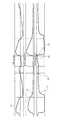
図4は、ベンチレータと患者との間の非同期性を伴う2回の「呼吸」に対する時間の関数としての流動24、圧力26及びCO228のプロットによって反復可能かつ信頼できる呼吸終期値を決定する際の問題のうちの一つを示す。PetCO2の測定される値は、PetCO2値がどのように定義されるかに依存する。例えば、呼吸終期のCO2がどのように決定されるかによって、それは、27, 30又は31 mmHgとして報告される可能性がある。図4において、位置82のPetCO2は27 mm Hgであり、位置84では31mm Hgであり、そして位置86では30mm Hgである。流動波形によって定義される呼吸の終わり(位置82)は、27 mm Hgの呼吸終期値をもたらす。しかしながら、カプノグラムからの明らかな呼息と吸息との間の遷移位置86を使用すると、30mmHgのPetCO2をもたらす。他方では、最も大きな値が用いられる場合(位置84)、31mmHgのPetCO2が得られる。FIG. 4 determines repeatable and reliable end-tidal values by plotting
従来は、時間又は体積測定カプノグラムのフェーズIIIの終期に向けての濃度は、肺胞性CO2濃度(すなわちPetCO2)の良好な推定量とみなされ、通常は呼吸ごとに決定される。先に述べたように、PetCO2を決定するための最も単純なアプローチは、一般的にフェーズIIIの間に発生する最大値を単に使用することである。極値がアーチファクト又は雑音に対してしばしば敏感であるので、他のアプローチはフェーズIIIの最後の部分にわたる平均を使用する場合があり、ここで、「最後の部分」は、時間又は呼気ボリュームに関して定義されることができる。Traditionally, the concentration towards the end of Phase III of the time or volumetric capnogram is considered a good estimate of the alveolar CO2 concentration (ie, PetCO2 ) and is usually determined on a respiration basis. As mentioned above, the simplest approach to determine PetCO2 is simply to use the maximum value that generally occurs during Phase III. Since extreme values are often sensitive to artifacts or noise, other approaches may use an average over the last part of Phase III, where “last part” is defined in terms of time or expiratory volume. Can be done.
呼吸終期の気体値が簡単かつ繰り返し決定されることができるように、本発明は、これらの他の技術と異なり、とりわけ有意な再呼吸が存在する場合に、より適切に呼息の終了を詳細に描写するために流動及び/又は圧力波形を使用することを意図する。同様に、ボリュームが流動の積分であるので、体積測定カプノグラムも同様に、より適切に呼息の終了を詳細に描写するのに用いられることができる(下記参照)。流動波形又は代用物が利用可能でない場合、本発明は、より適切に呼息の終了を詳細に描写するために、波形形状解析を使用することを意図する。 Unlike these other techniques, the present invention details the end of expiration more appropriately, especially in the presence of significant rebreathing, so that end-tidal gas values can be easily and repeatedly determined. It is intended to use flow and / or pressure waveforms to depict Similarly, since volume is an integral of flow, a volumetric capnogram can likewise be used to better detail the end of expiration (see below). If a flow waveform or surrogate is not available, the present invention contemplates using waveform shape analysis to better detail the end of expiration.
図5及び6は、時系列カプノグラムのみから呼吸終期の値を取得する際の潜在的な困難を示す時系列及び体積測定カプノグラムである。図5は、1:8〜1:10のI:E比による長い呼気休止を伴う新生児においてしばしば確認される現象を図示し、その間、非常に軽微な吸息労力が行われ、解釈するのが難しいカプノグラムをもたらす。そのような時系列カプノグラムを調査することは、呼吸終期値を決定することを非常に難しくする。しかしながら、図5及び6における時系列カプノグラムと体積測定ベースのカプノグラムとを比較することは、若干の明確性を可能にする。肺の換気と血流との関係は、フェーズIIIの勾配の傾斜が通常明確でなく、誤解をまねく可能性がある時系列カプノグラムの勾配におけるよりも、体積測定カプノグラムによるフェーズIIIの勾配において正確に反映されることに留意すべきである。これは、呼気のわずかなボリューム(おおよそ最後の15% )がしばしば呼息のために利用可能な時間の半分を占めて、CO2濃度における似かよった変化が、時系列カプノグラムにおいて、体積測定カプノグラムにおけるよりも長い期間にわたって分布するからである。FIGS. 5 and 6 are time series and volumetric capnograms showing potential difficulties in obtaining end-tidal values from time series capnograms only. Figure 5 illustrates the phenomenon often observed in neonates with long exhalation with an I: E ratio of 1: 8 to 1:10, during which very little inspiration effort is performed and interpreted. Brings a difficult capnogram. Examining such time series capnograms makes it very difficult to determine end-tidal values. However, comparing the time series capnograms in FIGS. 5 and 6 with the volumetric based capnogram allows for some clarity. The relationship between pulmonary ventilation and blood flow is more accurate in phase III gradients with volumetric capnograms than in time-series capnogram gradients where the slope of phase III gradients is usually not clear and can be misleading. It should be noted that it is reflected. This is because a small volume of expiratory volume (approximately the last 15%) often accounts for half of the time available for exhalation, and similar changes in CO2 concentration are observed in time series capnograms, volumetric capnograms. This is because it is distributed over a longer period.
図6において、呼息の間の呼気のボリューム v.s. CO2の分圧のプロットは明らかに平坦域90を示し、それから様々な方法を用いて呼吸終期値が決定されることができる。体積測定カプノグラフィと関連したパラメータの全てが同様に決定されることができる。例えば、呼吸終期の気体値は、ボリュームの最後のX%(例えば5又は10%)に対する平均PCO2値を計算し、(Weibelモデルのように生理学に基づいた、又は実験に基づいた)モデルに対して曲線又はその一部をフィッティングすることによって決定されることができる。濃度-ボリューム曲線をフィッティングするためにモデルベースのアプローチを使用することは、潜在的に臨床的に重要な値が決定されることを可能にする。In FIG. 6, a plot of exhaled volume during exhalation vs partial pressure of CO2 clearly shows a
すでに概説された課題に加えて、PetCO2値の決定及び臨床的使用における主要な課題のうちの一つは、PetCO2が肺胞性CO2濃度(PACO2)の平均値を表すという暗黙の仮定に由来する。CO2が呼息の間に血液から肺胞性気体フェーズに移り続けるので、肺胞性CO2濃度は呼息を通じて上昇する。吸息の間、CO2を含まない気体は、肺胞の気体を希釈する役目をして、肺胞のCO2濃度は低下する。呼吸流動波形(例えば、一回呼吸量、吸息時間と呼息時間の比)の形状、肺の毛細管血液流動、静脈CO2濃度、デッドスペースの量及び直列肺胞デッドスペースは、肺胞CO2濃度波形の特定の形に影響を及ぼす。この形状は、次に、平均肺胞CO2濃度に影響を及ぼす。肺を出る呼気のボリュームのまさに最後の部分は、気体センサ14に決して到達せず、解剖学的デッドスペース及び装置の(直列的)デッドスペース中にとどまる。Already in addition to problems outlined, one of the major challenges in the determination and clinical use of PetCO2 values, tacit PetCO2 represents the average value of the alveolar CO2 concentration (PA CO2) Derived from this assumption. As CO2 continues to move from the blood to the alveolar gas phase during exhalation, the alveolar CO2 concentration rises through exhalation. During inspiration, gas that does not contain CO2 serves to dilute the alveolar gas, reducing the alveolar CO2 concentration. Respiratory flow waveform (e.g., tidal volume, the ratio of inspiration time and expiration time) shape, the pulmonary capillary blood flow, the venous CO2 concentration, the amount and serial alveolar dead space dead space, alveolar CO2 affects the specific shape of the concentration waveform. This shape in turn affects the average alveolar CO2 concentration. The very last part of the expiratory volume leaving the lung never reaches the
シミュレートされた流動波形202、ボリューム波形204及び肺胞CO2濃度波形206を示す図8A及び8Bに示されるシミュレーションは、これがどのようにPetCO2に影響を及ぼす可能性があるか、及び平均肺胞CO2濃度に対するその関係を図示する。肺胞CO2濃度グラフ206及び306におけるライン210及び310は、平均肺胞濃度を示す。肺胞CO2濃度グラフ206及び306の太いライン220及び320は、カプノグラムの形で気体センサ14によって測定される肺胞波形の部分を図示する。従来は、太くされたライン220及び320の端部221及び321が、PetCO2として報告される。The simulations shown in FIGS. 8A and 8B showing the
図8Aは、肺胞と気体センサ14との間に直列的デッドスペースがない場合に観測される波形を図示する。結果として生じるPetCO2値(端部221)は、このシミュレーションにおいて平均肺胞CO2を過大評価する。図8Bは、通常の直列的デッドスペース(例えば150ml)が肺胞と気体センサ14との間にある場合に観測される波形を図示する。結果として生じるPetCO2値(端部321)は、このシミュレーションにおいて平均肺胞CO2を過小評価する。肺胞CO2濃度グラフ206及び306のステップサイズは、おおよそ4mmHgである。より大きなデッドスペース及びより小さな一回呼吸量は、PetCO2と平均肺胞CO2濃度との間の差分を増加させる場合がある。さらに、この効果は、自発的に呼吸する患者の一回呼吸量の呼吸間変動に起因して、PetCO2信号中の雑音を増加させる場合がある。FIG. 8A illustrates the waveform observed when there is no serial dead space between the alveoli and the
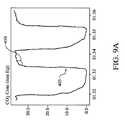
(気管内チューブの代わりに)フェイスマスクで呼吸する患者では、カプノグラムはさらに、フェースマスクボリュームの"不鮮明化"効果によって影響を受け、その上、小さな又は変動する一回呼吸量によって悪化する。この"不鮮明化"効果は、図9A及び9Bに示される。図9Aでは、患者はマウスピースによって呼吸しており、90°より僅かに大きいだけであるカプノグラム405のアルファ角410をもたらす。加えて、カプノグラム405は、比較的平坦なフェーズIIIを持つ。図9Bでは、同じ患者がフェイスマスクを通して呼吸しており、角度410より鈍角であるカプノグラム415のアルファ角420をもたらす。加えて、フェイスマスクのデッドスペースボリュームにおける希釈及び混合に主に起因して、カプノグラム415のフェーズIIIは、カプノグラム405よりも丸みを帯びている。一般に、PetCO2と平均肺胞CO2濃度との間の差分は、重大な換気血流異常を伴わないほとんどの被検者において比較的小さい(例えばおよそ2又は3mmHg程度)。しかしながら、PetCO2が更なる情報を抽出するために用いられる場合、例えば部分的なCO2再呼吸操作によって、これらのわずかな差分が有意になる可能性がある。In patients breathing with a face mask (instead of an endotracheal tube), the capnogram is further affected by the “blurring” effect of the face mask volume, and is further exacerbated by small or variable tidal volumes. This “smearing” effect is shown in FIGS. 9A and 9B. In FIG. 9A, the patient is breathing through the mouthpiece, resulting in an
本発明は、数学関数を用いて呼気の体積測定カプノグラムを近似することを意図する。(生理学的な及び計測による)大きな雑音の存在下と同様に、上で示されたような悪条件の下でカプノグラムを取得しようとする場合に、これは特に有用である。呼気の体積測定カプノグラムを近似するのに用いられることができる例示的な数学関数は、以下の形態のべき乗関数である。
invCO2= f x VEn
ここで、invCO2= CO2 - maxCO2、CO2は気体センサによって測定される呼気CO2、VEは呼気のボリューム、f及びnは近似パラメータ、そして、maxCO2はもう一つの近似パラメータである一定のCO2値である。The present invention contemplates approximating exhaled volumetric capnograms using mathematical functions. This is particularly useful when trying to obtain capnograms under adverse conditions as indicated above, as well as in the presence of large (physiological and instrumental) noise. An exemplary mathematical function that can be used to approximate the expiratory volumetric capnogram is a power function of the form:
invCO2 = fx VEn
Here, invCO 2 = CO 2 - maxCO 2,
近似パラメータf及びnは、自然対数(invCO2)対自然対数(VE)の線形回帰を含む既知の数値的方法によって見つけることができる。近似パラメータmaxCO2は、既知の探索法を繰り返し用いて又は従来の線形回帰よりも一般的な最小自乗アルゴリズムを用いて見つけることができる。The approximate parameters f and n can be found by known numerical methods including linear regression of natural logarithm (invCO2 ) vs natural logarithm (VE). The approximate parameter maxCO2 can be found using iterative search methods or using a general least squares algorithm rather than conventional linear regression.
図10は、累乗回帰曲線520によって近似される元のカプノグラム510の例を示す。複数のアプローチが、この累乗回帰近似からPetCO2相当値を決定するために意図される。一般に、PetCO2値は、一回呼吸量が大きな場合に肺胞CO2濃度をより忠実に表すはずである。一回呼吸量が小さな場合には、カプノグラム値が大きな呼気ボリュームにおいて持つであろう値に外挿するために、累乗回帰近似が用いられることができる。あるいは、累乗回帰近似は、全ての呼吸に対して、それらのボリュームの大小にかかわらず、一つの一定の呼気ボリュームにおけるPetCO2濃度を報告するように用いられることができる。FIG. 10 shows an example of the
本発明は、モデル派生PetCO2値が、従来通りに決定されたPetCO2値を肺の毛細管血液流動の示差CO2フィック決定に置き換えることと同様に、従来のCO2モニタにおいて従来通りに決定されたPetCO2値を置き換えるために用いられることができることを意図する。上で説明されたべき乗関数以外の他の近似関数も同様に意図される。近似パラメータは、線形回帰、最小二乗アルゴリズム、人工ニューラルネットワーク及び反復探索法(但しこれらに限られない)を含む、従来技術において周知の方法によって見つけることができる。近似パラメータを見つけ出すためのアルゴリズムはさらに、より速く、計算コストをかけずに、より正確に、現在の呼吸のための近似パラメータを見つけ出すために、以前の呼吸からの近似結果を考慮することができる。The present invention allows model-derived PetCO2 values to be determined conventionally in a conventional CO2 monitor, as well as replacing the conventionally determined PetCO2 value with a differential CO2 Fick determination of pulmonary capillary blood flow. It is intended to be used to replace the PetCO2 value. Other approximation functions other than the power function described above are contemplated as well. Approximate parameters can be found by methods well known in the art, including but not limited to linear regression, least squares algorithms, artificial neural networks, and iterative search methods. The algorithm for finding approximate parameters can further consider the approximation results from previous breaths to find the approximate parameters for the current breath more quickly, more accurately and without computational cost. .
本発明は、いつの呼吸終期CO2が(それがどのように決定されたとしても)、動脈内CO2の信頼できる現実的な推定値であるか、及び、いつの呼吸終期CO2が動脈内CO2の信頼できる現実的な推定値ではないかの、より良好な定義を提供することを意図する。これは、患者の心肺システムの生理学的状態と、患者の肺及び血液貯蔵にかなり影響を及ぼした可能性がある換気の最近のパターンの両方に関連している可能性がある。したがって、障害の程度を評価するための生理学的/肺胞性Vd/Vt又は代用物の推定及びCO2貯蔵に対する外乱の程度の評価は、呼吸終期のCO2値がより高い確かさで決定されて表示されることを可能にする。後で更に詳細に論じられる図7は、いつの呼吸終期CO2が動脈内CO2の信頼できる現実的な推定値であるか否かの指標を提供するための例示的なプロセス及び装置を図示する。The present invention determines when end-tidal CO2 (no matter how it is determined) is a reliable and realistic estimate of intra-arterial CO2 , and when end-tidal CO2 is intra-arterial CO2. It is intended to provide a better definition of whether this is a reliable and realistic estimate of2 . This may be related to both the physiological state of the patient's cardiopulmonary system and recent patterns of ventilation that may have had a significant impact on the patient's lung and blood storage. Therefore, the estimation of physiological / alveolar Vd / Vt or surrogate to assess the degree of injury and the degree of disturbance to CO2 storage is determined by the greater certainty of end-tidal CO2 values. To be displayed. FIG. 7, discussed in more detail later, illustrates an exemplary process and apparatus for providing an indication of when end-tidal CO2 is a reliable realistic estimate of intra-arterial CO2 .
本発明はさらに、生理学的障害の程度を決定することを意図する。生理学的Vd/Vtは、好ましくは、CO2の肺胞性分圧(PACO2)を使用して(Enghoff修正を伴わずにその定義で)推定される。PACO2は、ニューラルネットワーク、遺伝的アルゴリズム及び他のアプローチ又はアプローチの組み合わせと同様に、体積測定カプノグラムに対するモデルの適用によって推定されることができる。米国特許番号5,632,281は、肺胞性推定に用いられることができる動脈内推定のためのアプローチを説明する。VDalv/VTalvが同様に用いられることができ、そしてHardman他がこの比を推定するための方法を説明する。The present invention further contemplates determining the extent of a physiological disorder. Physiological Vd / Vt is preferably carried out using an alveolar partial pressure ofCO 2 (P A CO 2) ( in the definition without Enghoff modification) is estimated. PA CO2 can be estimated by applying the model to a volumetric capnogram, as well as neural networks, genetic algorithms and other approaches or combinations of approaches. US Pat. No. 5,632,281 describes an approach for intra-arterial estimation that can be used for alveolar estimation. VDalv / VTalv can be used as well, and Hardman et al. Describe a method for estimating this ratio.
本発明はさらに、外乱の程度を決定することを意図する。外乱の程度すなわち換気安定性は、異なる方法によって評価されることができる。例えば、CO2貯蔵に対する外乱の程度の評価は、「安定性」の期間をより適切に決定するために(モデルを用いた)換気の測定によって決定されることができる。CO2貯蔵を推定する方法は、米国特許第6,955,651号('651特許)に見つけ出されることができる(その内容が参照により本明細書に組み込まれる)。一回呼吸量は、解剖学的デッドスペースに対して十分なサイズでなければならない。機能性解剖学的デッドスペースは、ファウラー方法のような従来技術における既知の方法によって推定されることができる。呼吸終期値の信頼性は、呼吸終期の測定が行われる呼吸に対して呼気の流量に基づく基準を適用することによって、さらに高められる。これらの基準の適用は、信頼できる呼吸終期値の決定を可能にするのを助ける。The present invention further contemplates determining the degree of disturbance. The degree of disturbance or ventilation stability can be evaluated by different methods. For example, an assessment of the degree of disturbance to CO2 storage can be determined by measuring ventilation (using a model) to better determine the “stability” period. A method for estimating CO2 storage can be found in US Pat. No. 6,955,651 (the '651 patent), the contents of which are hereby incorporated by reference. The tidal volume must be large enough for the anatomical dead space. The functional anatomical dead space can be estimated by known methods in the prior art, such as the Fowler method. The reliability of end-tidal values is further enhanced by applying a criterion based on exhaled flow to the breath from which end-tidal measurements are made. The application of these criteria helps to allow reliable determination of end-tidal values.
上記したように、図7は、本発明の原理による気体測定システム100の例示的かつ模式的な実施の形態を図示する。気体測定システム100は、呼吸終期の気体濃度の信頼できる推定値を提供するのに用いられるシステムのコンポーネントを図示する。(可換に用いられる)気体濃度又は分圧値は、気体測定コンポーネント110によって決定される。これは、連続的又は断続的に決定されることができる。従来の気体濃度コンポーネントは、25〜100サンプル/secのサンプリングレートでサンプリングされるデータを提供した。気体測定コンポーネント110は、例えば、上記の図1における気体センサ14及びCO2信号ユニット18に対応する。As noted above, FIG. 7 illustrates an exemplary schematic embodiment of a
気道において又は他の技術を介して測定される換気値は、換気測定コンポーネント120によって決定される。換気値は、流動、ボリューム、圧力、温度及び湿度又はそれらの任意の組み合わせを含むが、これらに限定されるものではない。換気値は、連続的又は断続的に決定されることができる。換気測定コンポーネント120は、例えば、圧力差流量計12及び流動信号ユニット16に対応する。例示的な実施の形態において、換気に関連する値は、流動、ボリューム又はその代用物の測定によって決定される。企業(例えばAndromed)由来の外部表面センサからの音響測定から導き出される流動の代用物が意図される。 Ventilation values measured in the airway or via other techniques are determined by the
気体測定コンポーネント110及び換気測定コンポーネント120からの気体濃度値は、呼吸終期気体測定コンポーネント130によって受け取られる。本発明は、図1の処理ユニット20によって呼吸終期気体測定コンポーネント130を実装することを意図する。受け取られた換気値の特性は、呼吸終期気体測定コンポーネント130によって、気体濃度値からより確固たる呼吸終期の気体値を導き出すのに用いられる。例えば、気道中の呼気流動から吸気流動への変化を示す、受け取られた換気値における変化は、呼息の終了を時刻で詳細に描写するのに用いられる。これは、流動、ボリューム又はその代用物の値から達成されることができる。流動に対して、呼気流動(又は休止インターバルの場合のゼロ流動)から吸気流動へのゼロ交差の時刻が用いられることができる。ボリュームに対して、ボリュームが増加(又は横ばいのボリューム)から減少に転じる時刻が用いられることができる。同様に、音響測定に対して、呼気流動から吸気流動への変化は、既知の方法によって決定されることができる。 Gas concentration values from the
換気測定コンポーネント120からの値はさらに、換気安定性測定コンポーネント140によって受け取られる。本発明はさらに、図1の処理ユニット20によって換気安定性測定コンポーネント140を実装することを意図する。換気安定性は、換気値の履歴を評価して、その安定性を評価することによって決定されることができる。評価のための期間は、懸案の気体の気体貯蔵の大きさによって変動する。CO2及びO2に対して、考慮される気体貯蔵は、肺貯蔵及び血液貯蔵の両方である。評価される時間インターバルは、患者の大きさに基づく経験則と同様に、'651特許に開示されるような方法によって推定されることができる貯蔵の大きさに基づく。評価のための期間にわたる換気値のばらつきを決定する例示的な方法は、一回呼吸量値の分布の分析を含み、有意な過換気又は換気低下の期間が評価期間の間に観測される場合には、呼吸終期値は信頼できないと考えられる。本発明はさらに、換気安定性測定コンポーネント140が、気体測定コンポーネント110から値を受け取ることを意図する。The value from the
換気安定性測定コンポーネント140からの換気安定性及び呼吸終期測定コンポーネント130からの呼吸終期値の推定値は、決定支援システム150によって受け取られる。本発明はさらに、図1の処理ユニット20によって決定支援システム150を実装することを意図する。他の基準と同様にこれらの値を使用することにより、決定支援システム150は、呼吸終期値の信頼性を決定する。信頼性は、単に換気安定性の閾値に基づくことができ、数値的に又はグラフでホストシステムのディスプレイに示されることができる。呼吸終期の数字は、その信頼性を示すために色分けされていることができる(例えば、「信頼できない」、「疑わしい」、「信頼できる」のそれぞれは、赤、黄色、緑に色分けされる)。ユーザ又は他のシステムからの入力に基づいて、決定支援システム150は、ルールに基づくシステムとして構成されることができる。例えば、疾患と同様に患者の年齢は、生理学的境界(あいまいな又は難しい境界)が呼吸終期値の信頼性を示すのに用いられることを可能にする。呼吸終期値の信頼性を決定するために、決定支援システム150において、以前に示されたように、Vd/Vtの測定値を使用することも意図される。これは、単に追加的なルールであることができる(例えば、生理学的Vd/Vtのケースにおいて、生理学的Vd/Vt > 0.70の場合、呼吸終期のCO2値は、動脈内CO2の代用としてあまり信頼できない)。Estimates of ventilation stability from the ventilation
本発明が、現在最も実用的で好ましい実施の形態であると考えられるものに基づいて説明を目的として詳細に説明されたが、そのような詳細は、単にその目的のためであり、本発明は、開示された実施の形態には制限されず、それどころか、添付の請求の範囲の精神及び範囲内である修正及び均等なアレンジをカバーすることを意図することが理解されるべきである。例えば、本発明は、可能な範囲で、任意の実施の形態の一つ以上の特徴が、任意の他の実施の形態の一つ以上の特徴と組み合わせられることを意図することが理解されるべきである。 Although the present invention has been described in detail for purposes of illustration based on what is presently considered to be the most practical and preferred embodiment, such details are merely for purposes of the present invention. It is to be understood that the invention is not limited to the disclosed embodiments, but rather is intended to cover modifications and equivalent arrangements that are within the spirit and scope of the appended claims. For example, it is to be understood that the present invention contemplates that, to the extent possible, one or more features of any embodiment are combined with one or more features of any other embodiment. It is.
Claims (10)
Translated fromJapanese前記呼吸気体の濃度値を異なる時刻において複数測定し、
前記呼吸気体の換気に関する値を異なる時刻において複数測定し、
測定された前記呼吸気体の複数の濃度値から呼吸終期の動脈内の前記呼吸気体の濃度値を推定し、
前記呼吸気体の換気に関する値の履歴を評価して換気安定性の程度を決定し、
換気安定性の前記程度を用いて推定された前記呼吸終期の動脈内の呼吸気体の濃度値の信頼性の推定を提供する、方法。A method for indicating reliabilitywhen usinga measured end-respiratory respiratory gasconcentration valueto estimate therespiratory gasconcentration valuein an artery ,
Measuring apluralityof concentration values of therespiratory gas atdifferent times ;
A pluralityof valuesrelated to ventilationof therespiratory gas are measured atdifferent times ;
Theestimateddensity valuesof the respiratory gas in the arterial end-tidalplurality of density valuesof saidmeasuredbreathing gas,
Evaluating the historyof valuesrelatedto ventilationof therespiratory gas to determine the degree of ventilation stability;
Providing a reliability estimateof the concentration value ofthe respiratory gasin the end-tidalarteryestimated using the degree of ventilation stability.
前記呼吸気体の濃度値を異なる時刻において複数測定し、
前記呼吸気体の流量を異なる時刻において複数測定し、
前記流量から呼吸された前記呼吸気体の複数のボリューム値を決定し、
測定された前記呼吸気体の複数の濃度値から呼吸終期の動脈内の前記呼吸気体の濃度値を推定し、
前記流量及びボリューム値の履歴を評価して換気安定性の程度を決定し、
換気安定性の前記程度を用いて推定された前記呼吸終期の動脈内の呼吸気体の濃度値の信頼性の推定を提供する、方法。A method for indicating reliabilitywhen usinga measured end-respiratory respiratory gasconcentration valueto estimate therespiratory gasconcentration valuein an artery ,
Measuring apluralityof concentration values of therespiratory gas atdifferent times ;
Measuringthe flow rate of therespiratory gas atdifferent times ,
Determininga plurality of volume values of thebreathing gas breathed from theflow rate ;
Theestimateddensity valuesof the respiratory gas in the arterial end-tidalplurality of density valuesof saidmeasuredbreathing gas,
Evaluate theflow rate and volume valuehistory to determine the degree of ventilation stability;
Providing a reliability estimateof the concentration value ofthe respiratory gasin the end-tidalarteryestimated using the degree of ventilation stability.
前記呼吸気体の濃度値を異なる時刻において複数測定する手段、
前記呼吸気体の換気に関する値を異なる時刻において複数測定する手段、
測定された前記呼吸気体の複数の濃度値から呼吸終期の動脈内の前記呼吸気体の濃度値を推定する手段、
前記呼吸気体の換気に関する値の履歴を評価して換気安定性の程度を決定する手段、及び
換気安定性の前記程度を用いて推定された前記呼吸終期の動脈内の呼吸気体の濃度値の信頼性の推定を提供する手段、
を有する装置。A device for improving the reliabilitywhen using themeasuredrespiratory gasconcentration valueat the end ofbreathingto estimate the concentration value of the respiratory gas in the artery ,
Means formeasuring apluralityof concentration values of therespiratory gas atdifferent times ;
Means formeasuring apluralityof valuesrelated to ventilationof therespiratory gas atdifferent times ;
It means forestimating thedensity valueof the breathing gas in the arterial end-tidalplurality of density valuesof saidmeasuredbreathing gas,
Meansfor evaluating a historyof valuesrelatingto ventilationof thebreathing gas to determine the degree of ventilation stability, and confidence inthe concentration value ofthe breathing gasin the end-breathingarteryestimated using the degree of ventilation stability Means to provide gender estimates,
Having a device.
Applications Claiming Priority (5)
| Application Number | Priority Date | Filing Date | Title |
|---|---|---|---|
| US91818907P | 2007-03-15 | 2007-03-15 | |
| US60/918,189 | 2007-03-15 | ||
| US12/046,808US8166971B2 (en) | 2007-03-15 | 2008-03-12 | End-tidal gas estimation system and method |
| US12/046,808 | 2008-03-12 | ||
| PCT/US2008/056902WO2008112927A2 (en) | 2007-03-15 | 2008-03-13 | End-tidal gas estimation system and method |
Publications (2)
| Publication Number | Publication Date |
|---|---|
| JP2010521243A JP2010521243A (en) | 2010-06-24 |
| JP5431971B2true JP5431971B2 (en) | 2014-03-05 |
Family
ID=39760408
Family Applications (1)
| Application Number | Title | Priority Date | Filing Date |
|---|---|---|---|
| JP2009553787AExpired - Fee RelatedJP5431971B2 (en) | 2007-03-15 | 2008-03-13 | End-breathing gas estimation system and method |
Country Status (5)
| Country | Link |
|---|---|
| US (1) | US8166971B2 (en) |
| EP (1) | EP2124744B1 (en) |
| JP (1) | JP5431971B2 (en) |
| CN (1) | CN101636109B (en) |
| WO (1) | WO2008112927A2 (en) |
Families Citing this family (30)
| Publication number | Priority date | Publication date | Assignee | Title |
|---|---|---|---|---|
| US8021308B2 (en) | 2003-06-19 | 2011-09-20 | Capnia, Inc. | Breath end-tidal gas monitor |
| WO2009144731A2 (en)* | 2008-05-28 | 2009-12-03 | Oridion Medical 1987 Ltd. | Methods, apparatus and systems for monitoring co2 |
| WO2010001390A1 (en)* | 2008-06-30 | 2010-01-07 | Oridion Medical 1987 Ltd. | Ventilation analysis and monitoring |
| BRPI0914093A2 (en)* | 2008-10-15 | 2015-10-27 | Koninkl Philips Electronics Nv | system configured for respiratory failure detection, respiratory failure detection method |
| JP2013533760A (en) | 2010-06-10 | 2013-08-29 | オリディオン メディカル 1987 リミテッド | Weaning from artificial respiration using capnography |
| CN102266606B (en)* | 2010-12-31 | 2014-06-11 | 北京谊安医疗系统股份有限公司 | End-expiratory detection method and device |
| JP5747262B2 (en)* | 2011-05-12 | 2015-07-08 | 泉工医科工業株式会社 | MONITOR SYSTEM CONTROL METHOD AND MONITOR SYSTEM |
| CN103813825B (en) | 2011-09-22 | 2017-01-18 | 皇家飞利浦有限公司 | Method and apparatus for monitoring and controlling pressure support equipment |
| RU2606453C2 (en) | 2011-12-03 | 2017-01-10 | Конинклейке Филипс Н.В. | Automatic depth scrolling and orientation adjustment for semi-automated path planning |
| CN102564521B (en)* | 2011-12-07 | 2014-01-15 | 深圳市普博科技有限公司 | Anesthetic dosage calculation method and anesthetic dosage calculation system for anesthesia machine |
| KR20150024299A (en) | 2011-12-21 | 2015-03-06 | 카프니아, 인코포레이티드 | Collection and analysis of a volume of exhaled gas with compensation for the frequency of a breathing parameter |
| WO2013093873A1 (en)* | 2011-12-23 | 2013-06-27 | Koninklijke Philips Electronics N.V. | Method and apparatus for monitoring and controlling a pressure support device |
| EP2797505A1 (en)* | 2011-12-27 | 2014-11-05 | Koninklijke Philips N.V. | Respiratory measurement apparatus having integrated filter |
| WO2013141766A1 (en)* | 2012-03-21 | 2013-09-26 | Maquet Critical Care Ab | Method for continuous and non-invasive determination of effective lung volume and cardiac output |
| EP2644094B1 (en)* | 2012-03-26 | 2018-03-14 | General Electric Company | Sensor, gas analyzer and method for measuring concentration of at least one respiratory gas component |
| DE102012024672A1 (en)* | 2012-12-18 | 2014-06-18 | Dräger Medical GmbH | Respirator and method of operating a ventilator |
| JP6424172B2 (en) | 2013-01-08 | 2018-11-14 | キャプニア, インク.Capnia, Inc. | Breathing selection for analysis |
| CN105101873A (en) | 2013-02-12 | 2015-11-25 | 卡普尼亚公司 | Sampling and storage registry device for breath gas analysis |
| CA2922356C (en) | 2013-08-30 | 2023-01-03 | Capnia, Inc. | Neonatal carbon dioxide measurement system |
| EP4356828A1 (en)* | 2014-09-04 | 2024-04-24 | Fisher & Paykel Healthcare Limited | Exhaled gas measurement compensation during high flow respiratory therapy |
| CN107106083B (en)* | 2014-12-30 | 2021-04-09 | 皇家飞利浦有限公司 | Capnometry system with supplemental oxygen detection and method of operating same |
| EP4186548A1 (en) | 2015-04-02 | 2023-05-31 | Hill-Rom Services PTE. LTD. | Mask leakage detection for a respiratory device |
| US20170347917A1 (en)* | 2016-06-06 | 2017-12-07 | General Electric Company | Newborn respiration monitoring system and method |
| KR101905067B1 (en) | 2016-11-29 | 2018-10-05 | 한국기계연구원 | Analysis method of single breath and analysis device of single breath |
| CN110506107A (en) | 2016-11-30 | 2019-11-26 | 阿德瓦希斯公司 | Immunogenic compositions targeting recurrent cancer mutations and methods of use |
| CN106680429A (en)* | 2016-12-26 | 2017-05-17 | 江南大学 | Life detection device and application thereof |
| CN108267182A (en)* | 2017-01-04 | 2018-07-10 | 沈阳新松医疗科技股份有限公司 | The lung function instrument and method of a kind of synchro measure breathing gas flow and content |
| MX2020004829A (en)* | 2017-11-08 | 2020-11-11 | Advaxis Inc | IMMUNOGENIC HETEROCLITIC PEPTIDES OF PROTEINS ASSOCIATED WITH CANCER AND METHODS OF USE THEREOF. |
| US11324954B2 (en) | 2019-06-28 | 2022-05-10 | Covidien Lp | Achieving smooth breathing by modified bilateral phrenic nerve pacing |
| CN111407280B (en)* | 2020-03-10 | 2022-04-15 | 山东大学 | End-tidal CO of noninvasive ventilator2Monitoring device and method |
Family Cites Families (18)
| Publication number | Priority date | Publication date | Assignee | Title |
|---|---|---|---|---|
| US4680808A (en) | 1986-01-03 | 1987-07-14 | Maurice Paleschuck | Compactor receptacle |
| EP1516639B2 (en)* | 1990-12-05 | 2015-04-15 | The General Hospital Corporation | Use of NO for treating persistent pulmonary hypertension of the newborn |
| JPH05137789A (en)* | 1991-11-20 | 1993-06-01 | 章 ▲はし▼内 | Measuring machine for continuous and bloodless measurement of concentration of anesthetic inhaled into patient's blood during general anesthesia |
| US5632281A (en) | 1995-02-06 | 1997-05-27 | Rayburn; Daniel B. | Non-invasive estimation of arterial blood gases |
| US5800361A (en)* | 1995-02-06 | 1998-09-01 | Ntc Technology Inc. | Non-invasive estimation of arterial blood gases |
| JPH10186A (en)* | 1996-06-17 | 1998-01-06 | Mitoreeben Kenkyusho:Kk | Method and device of analyzing specified gas component in expired air |
| US5915379A (en) | 1997-03-14 | 1999-06-29 | Nellcor Puritan Bennett Incorporated | Graphic user interface for a patient ventilator |
| US6099481A (en) | 1997-11-03 | 2000-08-08 | Ntc Technology, Inc. | Respiratory profile parameter determination method and apparatus |
| IL130371A (en)* | 1999-06-08 | 2004-06-01 | Oridion Medical Ltd | Capnography waveform interpreter |
| US6540689B1 (en) | 2000-02-22 | 2003-04-01 | Ntc Technology, Inc. | Methods for accurately, substantially noninvasively determining pulmonary capillary blood flow, cardiac output, and mixed venous carbon dioxide content |
| US7135001B2 (en) | 2001-03-20 | 2006-11-14 | Ric Investments, Llc | Rebreathing methods including oscillating, substantially equal rebreathing and nonrebreathing periods |
| US6544190B1 (en)* | 2001-08-03 | 2003-04-08 | Natus Medical Inc. | End tidal breath analyzer |
| WO2003067216A2 (en)* | 2002-02-05 | 2003-08-14 | The Regents Of The University Of California | Flow-independent parameter estimation |
| CA2379353C (en)* | 2002-03-28 | 2012-07-31 | Joseph Fisher | A new method for continuous measurement of flux of gases in the lungs during breathing |
| JP2004077467A (en)* | 2003-06-16 | 2004-03-11 | Mitoreeben Kenkyusho:Kk | Sampling method and device of end expiration |
| CN2770576Y (en)* | 2005-02-07 | 2006-04-12 | 蔡永良 | Lung aerating image reconstructor |
| US20080009762A1 (en) | 2006-06-27 | 2008-01-10 | Medtronic Emergency Response Systems, Inc. | Method and apparatus for interpreting capnographic data |
| US8312879B2 (en)* | 2006-10-16 | 2012-11-20 | General Electric Company | Method and apparatus for airway compensation control |
- 2008
- 2008-03-12USUS12/046,808patent/US8166971B2/enactiveActive
- 2008-03-13CNCN2008800083030Apatent/CN101636109B/ennot_activeExpired - Fee Related
- 2008-03-13JPJP2009553787Apatent/JP5431971B2/ennot_activeExpired - Fee Related
- 2008-03-13WOPCT/US2008/056902patent/WO2008112927A2/enactiveApplication Filing
- 2008-03-13EPEP08732153Apatent/EP2124744B1/enactiveActive
Also Published As
| Publication number | Publication date |
|---|---|
| JP2010521243A (en) | 2010-06-24 |
| US20080228096A1 (en) | 2008-09-18 |
| EP2124744A4 (en) | 2011-09-07 |
| WO2008112927A3 (en) | 2008-11-06 |
| CN101636109B (en) | 2013-09-11 |
| CN101636109A (en) | 2010-01-27 |
| WO2008112927A2 (en) | 2008-09-18 |
| US8166971B2 (en) | 2012-05-01 |
| EP2124744A2 (en) | 2009-12-02 |
| EP2124744B1 (en) | 2012-11-28 |
Similar Documents
| Publication | Publication Date | Title |
|---|---|---|
| JP5431971B2 (en) | End-breathing gas estimation system and method | |
| US8176915B2 (en) | End-tidal gas estimation system and method | |
| Gold et al. | Pulmonary function testing | |
| Verscheure et al. | Volumetric capnography: lessons from the past and current clinical applications | |
| US5800361A (en) | Non-invasive estimation of arterial blood gases | |
| US5632281A (en) | Non-invasive estimation of arterial blood gases | |
| EP1257201B1 (en) | Noninvasive determination of cardiac output, pulmonary blood flow, and blood gas content | |
| Balogh et al. | Capnogram slope and ventilation dead space parameters: comparison of mainstream and sidestream techniques | |
| DK2311371T3 (en) | The combination of the inert gas-rebreathing breathing and multi-leaching techniques to determine the indicators ventilationsuensartethed | |
| Lucangelo et al. | Dead space | |
| Heinze et al. | The accuracy of the oxygen washout technique for functional residual capacity assessment during spontaneous breathing | |
| Balakrishnan et al. | Clinical application of pulmonary function testing in small animals | |
| US20060004297A1 (en) | Lung model-based cardiopulmonary performance determination | |
| EP3506826B1 (en) | Method and apparatus for quantifying lung function | |
| Riou et al. | Reproducibility of the respiratory dead space measurements in mechanically ventilated children using the CO2SMO monitor | |
| Nagler et al. | Capnographic monitoring in respiratory emergencies | |
| Harrison et al. | Modelling mixing within the dead space of the lung improves predictions of functional residual capacity | |
| Tang et al. | Systematic errors and susceptibility to noise of four methods for calculating anatomical dead space from the CO2 expirogram | |
| Sylvester et al. | Respiratory measurement | |
| Den Buijs et al. | Bayesian tracking of a nonlinear model of the capnogram | |
| Mehra et al. | Evaluation and monitoring of respiratory function | |
| Hess | Noninvasive respiratory monitoring during ventilatory support | |
| Karbing et al. | Journal of Clinical Monitoring and Computing 2016 end of year summary: respiration | |
| Schivo et al. | The Use of the Pulmonary Function Laboratory in Diagnosing Asthma | |
| Tunnicliffe et al. | Respiratory |
Legal Events
| Date | Code | Title | Description |
|---|---|---|---|
| A621 | Written request for application examination | Free format text:JAPANESE INTERMEDIATE CODE: A621 Effective date:20110311 | |
| A977 | Report on retrieval | Free format text:JAPANESE INTERMEDIATE CODE: A971007 Effective date:20121023 | |
| A131 | Notification of reasons for refusal | Free format text:JAPANESE INTERMEDIATE CODE: A131 Effective date:20121101 | |
| A601 | Written request for extension of time | Free format text:JAPANESE INTERMEDIATE CODE: A601 Effective date:20130130 | |
| A602 | Written permission of extension of time | Free format text:JAPANESE INTERMEDIATE CODE: A602 Effective date:20130206 | |
| A521 | Request for written amendment filed | Free format text:JAPANESE INTERMEDIATE CODE: A523 Effective date:20130418 | |
| TRDD | Decision of grant or rejection written | ||
| A01 | Written decision to grant a patent or to grant a registration (utility model) | Free format text:JAPANESE INTERMEDIATE CODE: A01 Effective date:20131105 | |
| A61 | First payment of annual fees (during grant procedure) | Free format text:JAPANESE INTERMEDIATE CODE: A61 Effective date:20131205 | |
| R150 | Certificate of patent or registration of utility model | Free format text:JAPANESE INTERMEDIATE CODE: R150 Ref document number:5431971 Country of ref document:JP Free format text:JAPANESE INTERMEDIATE CODE: R150 | |
| R250 | Receipt of annual fees | Free format text:JAPANESE INTERMEDIATE CODE: R250 | |
| R250 | Receipt of annual fees | Free format text:JAPANESE INTERMEDIATE CODE: R250 | |
| R250 | Receipt of annual fees | Free format text:JAPANESE INTERMEDIATE CODE: R250 | |
| R250 | Receipt of annual fees | Free format text:JAPANESE INTERMEDIATE CODE: R250 | |
| R250 | Receipt of annual fees | Free format text:JAPANESE INTERMEDIATE CODE: R250 | |
| R250 | Receipt of annual fees | Free format text:JAPANESE INTERMEDIATE CODE: R250 | |
| R250 | Receipt of annual fees | Free format text:JAPANESE INTERMEDIATE CODE: R250 | |
| LAPS | Cancellation because of no payment of annual fees |