JP5431270B2 - Endoscope tip cover and endoscope - Google Patents
Endoscope tip cover and endoscopeDownload PDFInfo
- Publication number
- JP5431270B2 JP5431270B2JP2010182581AJP2010182581AJP5431270B2JP 5431270 B2JP5431270 B2JP 5431270B2JP 2010182581 AJP2010182581 AJP 2010182581AJP 2010182581 AJP2010182581 AJP 2010182581AJP 5431270 B2JP5431270 B2JP 5431270B2
- Authority
- JP
- Japan
- Prior art keywords
- endoscope
- main body
- body side
- distal end
- tip
- Prior art date
- Legal status (The legal status is an assumption and is not a legal conclusion. Google has not performed a legal analysis and makes no representation as to the accuracy of the status listed.)
- Active
Links
Images


Landscapes
- Laser Surgery Devices (AREA)
- Surgical Instruments (AREA)
- Endoscopes (AREA)
Description
Translated fromJapaneseこの発明は、例えば内視鏡の先端構成部に装着して施術や観察をサポートするような内視鏡先端カバーおよび該内視鏡に関する。 The present invention relates to an endoscope distal end cover that is attached to, for example, an endoscope distal end configuration portion to support treatment and observation, and the endoscope.
従来、患者への負担が少なく治療できる治療方法として、内視鏡を用いる治療方法が実施されている。この内視鏡を用いた治療は、内視鏡チューブを口腔等から体内に挿入し、この内視鏡チューブの先端構成部を用いて撮像や施術を行うものである。 Conventionally, a treatment method using an endoscope has been implemented as a treatment method that can be treated with less burden on the patient. In the treatment using this endoscope, the endoscope tube is inserted into the body from the oral cavity or the like, and imaging and treatment are performed using the distal end configuration portion of the endoscope tube.
撮像は、先端構成部から照明光を照射し、この照明光の反射光を前記先端構成部に設けられたレンズで受け取って内視鏡チューブから内視鏡本体装置に伝送し、内視鏡本体装置が画像化して表示装置に表示することで実行される。 The imaging is performed by irradiating illumination light from the tip component, receiving reflected light of the illumination light by a lens provided in the tip component, and transmitting the light from the endoscope tube to the endoscope body device. This is executed by the device imaging and displaying on the display device.
施術は、チャンネルと呼ばれる鉗子挿入口から適宜の鉗子が挿入され、先端構成部の鉗子出口から出てくる鉗子先端により実施される。鉗子としては、握持鉗子やナイフ等の様々な器具が用いられる。 The treatment is performed by a forceps tip that is inserted from a forceps insertion opening called a channel and comes out from the forceps outlet of the tip constituting portion. As the forceps, various instruments such as a gripping forceps and a knife are used.
ここで、内視鏡の先端構成部に装着するカバーとして、様々な形態のものが提案されている。 Here, various types of covers have been proposed as a cover to be attached to the distal end configuration portion of the endoscope.
例えば、傾斜した開口部を有する透明な内視鏡用フードが提案されている(特許文献1参照)。この内視鏡フードは、高周波ナイフとの併用を想定したものであり、傾斜開口部の下方の突出部分をヘラ部としている。そして、その突出しているヘラ部によって粘膜を剥離させ、この状態で高周波ナイフを剥離部に挿入して施術するようにして用いられる。 For example, a transparent endoscope hood having an inclined opening has been proposed (see Patent Document 1). This endoscope hood is assumed to be used in combination with a high-frequency knife, and the protruding portion below the inclined opening is a spatula portion. Then, the mucous membrane is peeled off by the protruding spatula portion, and in this state, a high-frequency knife is inserted into the peeling portion and used for treatment.
また、略円筒形の内視鏡フードも提案されている(特許文献2参照)。この内視鏡フードは、粘膜切除部分を囲うようにして粘膜に密着し、内視鏡のチャンネルを通じて吸引することで粘膜切除部分を隆起させ、この隆起部分をスネアワイヤーによって緊縛して切除するようにして用いられる。 A substantially cylindrical endoscope hood has also been proposed (see Patent Document 2). This endoscopic hood is closely attached to the mucous membrane so as to surround the mucosal resection part, and the mucosal excision part is raised by suction through the channel of the endoscope, and this bulging part is bound and removed by a snare wire. Used.
また、レーザガイドの射出先端の先方に処置部位を取り込む空間部を形成して、その先端にレーザ光を遮蔽する遮蔽部材を備えたレーザプローブも提案されている(特許文献3参照)。このレーザプローブは、血栓をレーザ光によって切除する際に、この血栓を空間部に位置させて処置することにより、レーザ光が遮蔽部材より先へ進むことがないため、安全に処置できるものである。 There has also been proposed a laser probe that has a space portion for taking a treatment site at the tip of an emission tip of a laser guide and includes a shielding member that shields laser light at the tip (see Patent Document 3). In this laser probe, when the thrombus is excised with a laser beam, the thrombus is positioned in the space portion and treated so that the laser beam does not travel beyond the shielding member, so that it can be treated safely. .
しかし、これらの特許文献に記載の器具では、腫瘍周囲を切り出す粘膜下層切開剥離術(ESD)にてレーザ光を使用して施術することには適していなかった。 However, the devices described in these patent documents are not suitable for performing treatment using laser light in submucosal dissection and exfoliation (ESD) that cuts out the periphery of the tumor.
この発明は、上述した問題に鑑み、レーザ光による組織の剥離術に適した内視鏡先端カバーを提供し、施術者の利便性を向上させることを目的とする。 In view of the above-described problems, an object of the present invention is to provide an endoscope distal end cover suitable for tissue detachment using laser light, and to improve the convenience of a practitioner.
この発明は、内視鏡チューブの先端構成部に装着される内視鏡先端カバーであって、前記内視鏡チューブの先端構成部に装着する装着部と、施術対象の本体に前記装着部より先端側の位置で当接する本体側当接部と、前記施術対象から剥離する剥離対象を前記装着部より先端側の位置で持ち上げる剥離対象支持部と、前記本体側当接部と前記剥離対象支持部とを略同時に開閉運動させる連関部とを備えた内視鏡先端カバーであることを特徴とする。ここで、剥離対象を持ち上げるとは、必ずしも鉛直方向における上方向への持ち上げを意味するわけではなく、あくまで本体当接部に対して剥離対象支持部を剥離する方向、つまり内視鏡先端カバーの開方向へ押しのけることを言うものとする。 The present invention relates to an endoscope tip cover to be attached to a distal end configuration portion of an endoscope tube, an attachment portion to be attached to the distal end configuration portion of the endoscope tube, and a body to be treated from a mounting portion to the main body. A main body side contact portion that contacts at a distal end side position, a separation target support portion that lifts a separation target that separates from the treatment target at a position closer to the distal end side than the mounting portion, the main body side contact portion, and the separation target support It is an endoscope tip cover provided with an associating part that opens and closes the part substantially simultaneously. Here, lifting the separation target does not necessarily mean upward lifting in the vertical direction, but only the direction in which the separation target support part is peeled from the main body contact part, that is, the endoscope tip cover. Say to push in the opening direction.
前記装着部は、先端構成部の外周に嵌合して装着するリング状(あるいは楕円形や四角形や多角形などその他の形状)の嵌合式装着部、先端構成部に設けたネジ止めに螺合して装着する螺子状の螺合式装着部、あるいは、先端構成部に凹部や凸部といった係合部が設けられている場合に該係合部に係合する係合装着部など、適宜の装着部で構成することができる。 The mounting part is a ring-shaped (or other shape such as an ellipse, quadrangle, or polygon) that fits and fits on the outer periphery of the tip component part, and is screwed into a screw stop provided on the tip component part. Appropriate mounting, such as a screw-type threaded mounting portion to be mounted or an engagement mounting portion that engages with the engagement portion such as a concave portion or a convex portion at the tip configuration portion It can consist of parts.
前記本体側当接部および前記剥離対象支持部は、前記装着部と一体形成されて該装着部に接続されるか、あるいは、前記装着部と別体に形成されて蝶番やピンやビスなどの適宜の接続部材により前記装着部に接続されるなど、適宜の方法により前記装着部と接続されることができる。前記本体側当接部と装着部との接続と、前記剥離対象支持部と装着部との接続とは、同じ接続方法とするか、あるいは異なる接続方法とすることができる。また、前記本体側当接部および前記剥離対象支持部は、単一部材によって形成されるか、あるいは、各々を別体に形成した後前記の接続方法によって一体形成されることができる。 The main body side abutting portion and the peeling target support portion are formed integrally with the mounting portion and connected to the mounting portion, or formed separately from the mounting portion, such as hinges, pins, screws, etc. It can be connected to the mounting portion by an appropriate method, such as being connected to the mounting portion by an appropriate connection member. The connection between the main body side contact portion and the mounting portion and the connection between the separation target support portion and the mounting portion may be the same connection method or different connection methods. In addition, the main body side contact portion and the separation target support portion may be formed by a single member, or may be integrally formed by the above connection method after being formed separately.
前記連関部は、前記本体側当接部および前記剥離対象支持部と一体形成された伸縮可能な接続部分としたり、前記本体側当接部と前記剥離対象支持部とを回動可能に接続するヒンジ部材としたり、あるいは前記本体側当接部と前記剥離対象支持部とを開閉可能に接続する接続アームとしたりするなど、適宜の構成とすることができる。 The associating part may be an extendable connecting part integrally formed with the main body side abutting part and the peeling target support part, or the main body side abutting part and the peeling target support part are rotatably connected. An appropriate configuration may be employed, such as a hinge member or a connection arm that connects the main body side contact portion and the separation target support portion so as to be openable and closable.
この発明により、レーザ光による組織の剥離術に適した内視鏡先端カバーを提供することができる。すなわち、施術対象の本体と剥離対象との間に内視鏡先端カバーを位置させて前記本体側当接部および前記剥離対象支持部を開くことで、施術対象の本体と剥離対象を押し広げることができ、レーザ光を照射する部位を明瞭に露出させることができるとともに術野および視野の確保ができる。さらに、施術対象の本体と剥離対象とを互いに剥離する方向へ外力を加えることにより、両者間の組織が緊張し、剥離術での剥離作業効率を向上させることができる。 According to the present invention, it is possible to provide an endoscope distal end cover suitable for tissue detachment using laser light. That is, the endoscope tip cover is positioned between the treatment target main body and the separation target, and the main body side contact portion and the separation target support portion are opened, thereby expanding the treatment target main body and the separation target. In addition, it is possible to clearly expose a portion irradiated with laser light and to secure an operative field and a visual field. Furthermore, by applying an external force in a direction in which the body to be treated and the object to be peeled are peeled from each other, the tissue between the two is strained, and the peeling work efficiency in the peeling operation can be improved.
この発明の態様として、前記連関部は、少なくとも前記本体側当接部が前記施術対象の本体側に当接した状態にあるか、もしくは前記剥離対象支持部が前記剥離対象を支持した状態で、前進移動されると前記本体側当接部と前記剥離対象支持部とを開動し、後退移動されると前記本体側当接部と前記剥離対象支持部とを閉動する構成とすることができる。 As an aspect of the present invention, the associating portion is in a state where at least the main body side contact portion is in contact with the main body side of the treatment target, or the separation target support portion supports the separation target, When moved forward, the main body side contact portion and the separation target support portion are opened, and when moved backward, the main body side contact portion and the separation target support portion are closed. .
これにより、前進移動させるという簡単な操作により、施術対象の本体部と剥離対象との間を押し広げることができ、施術する部位を明瞭に露出させることができるとともに術野および視野の確保ができる。さらに、施術対象の本体と剥離対象とを互いに剥離する方向へ外力を加えることにより、両者間の組織が緊張し、剥離術での剥離作業効率を向上させることができる。また、後退移動させるという簡単な操作により、施術対象の本体部と剥離対象との間の組織が剥離方向へ緊張するのを緩和でき、内視鏡の先端位置調整などの際にはスムーズに内視鏡を操作することができるため、内視鏡先端カバーと当接する組織の摩擦負担を軽減することができる。 Thereby, by a simple operation of moving forward, the space between the main body part to be treated and the object to be peeled can be expanded, the part to be treated can be clearly exposed and the surgical field and visual field can be secured. . Furthermore, by applying an external force in a direction in which the body to be treated and the object to be peeled are peeled from each other, the tissue between the two is strained, and the peeling work efficiency in the peeling operation can be improved. In addition, the simple operation of moving backward can alleviate the tension between the body part to be treated and the object to be peeled in the peeling direction, so that the inner part of the endoscope can be smoothly adjusted when adjusting the tip position of the endoscope. Since the endoscope can be operated, it is possible to reduce the frictional burden on the tissue in contact with the endoscope front end cover.
またこの発明の態様として、前記本体側当接部の先端側外周部に、前記施術対象の本体側に当接し且つ該本体側方向へ凸となる本体側凸部を備え、前記剥離対象支持部の先端側外周部に、前記剥離対象を支持し且つ剥離対象側方向へ凸となる剥離対象側凸部を備えることができる。 Further, as an aspect of the present invention, the outer peripheral portion on the distal end side of the main body side contact portion includes a main body side convex portion that comes into contact with the main body side of the treatment target and is convex in the main body side direction, The peeling target side convex part which supports the said peeling object and becomes convex in the peeling object side direction can be provided in the front end side outer peripheral part.
前記本体側凸部と前記剥離対象側凸部は、硬い部材による凸部、粘膜等の体内組織を傷つけない程度に軟らかくしなやかな部材による凸部、外周方向へ略直角に突出する凸部、あるいは先端側から基部側へ向かって突出する凸部など、適宜の素材により適宜の形状に形成することができる。
この態様により、滑り止め効果を発揮して、当接する組織に対して内視鏡先端カバーをしっかりと位置決めしながら該カバーの開動を容易にすることができ、また、押しのけた剥離対象が内視鏡先端カバーに凭れ掛かる場合に該カバーから剥離対象がズレ落ちて剥離作業を妨害することを防止でき、施術効率を向上させることができる。The main body side convex portion and the separation target side convex portion are a convex portion formed by a hard member, a convex portion formed by a soft and flexible member that does not damage a body tissue such as a mucous membrane, a convex portion protruding substantially at right angles to the outer circumferential direction, or It can be formed in an appropriate shape with an appropriate material, such as a convex portion protruding from the distal end side toward the base side.
According to this aspect, the antiskid effect can be exerted, the endoscope tip cover can be easily positioned with respect to the abutting tissue, and the opening of the cover can be facilitated. When the mirror tip cover is dripped, it is possible to prevent the object to be peeled off from the cover and prevent the peeling operation from being disturbed, thereby improving the treatment efficiency.
またこの発明の態様として、前記装着部と前記本体側当接部と前記剥離対象支持部と前記連関部とを、外力によって変形する可撓性素材により一体形成することができる。 As an aspect of the present invention, the mounting portion, the main body side contact portion, the separation target support portion, and the linkage portion can be integrally formed of a flexible material that is deformed by an external force.
これにより、部品点数を減らすことができる。従って、コストダウンを図ることができ、また、体内での部品の抜け落ちを防止することができる。 Thereby, the number of parts can be reduced. Therefore, the cost can be reduced and parts can be prevented from falling off in the body.
またこの発明の態様として、前記連関部を、前記本体側当接部と前記剥離対象支持部とを相対回転可能に支持するヒンジ部材により形成することができる。
これにより、前記本体側当接部と前記剥離対象支持部との相対回転による開閉動作を良好に行うことができる。従って、湾曲、伸縮等による構成部材への負荷を低減でき、作業に対する耐性の高い部品を提供することができる。As an aspect of the present invention, the linkage portion can be formed by a hinge member that supports the main body side contact portion and the separation target support portion so as to be relatively rotatable.
Thereby, the opening / closing operation | movement by the relative rotation of the said main body side contact part and the said peeling object support part can be performed favorably. Therefore, it is possible to reduce the load on the constituent members due to bending, expansion and contraction, etc., and it is possible to provide a component with high resistance to work.
またこの発明の態様として、前記本体側当接部と前記剥離対象支持部とを、互いに開方向または閉方向へ付勢する付勢手段を備えることができる。
前記付勢手段は、コイル型のコイルバネ、コイル型両端からアームが伸びるねじりバネ、板状部材を折り曲げた板バネ、あるいはゴムなど、付勢力を発揮する適宜の手段で構成することができる。
この態様により、開動作または閉動作を付勢手段によって補助することができ、使用者は小さい力でも十分に開状態とする、あるいは容易に十分に閉状態とするなど操作性の向上を図ることができる。Further, as an aspect of the present invention, it is possible to include a biasing unit that biases the main body side contact portion and the separation target support portion in the opening direction or the closing direction.
The urging means can be constituted by an appropriate means that exerts an urging force, such as a coil type coil spring, a torsion spring in which an arm extends from both ends of the coil type, a plate spring obtained by bending a plate member, or rubber.
According to this aspect, the opening operation or the closing operation can be assisted by the urging means, and the user can improve the operability such as sufficiently opening it with a small force or easily closing it sufficiently. Can do.
またこの発明は、湾曲可能な内視鏡チューブと、該内視鏡チューブの先端側に設けられる先端構成部と、該先端構成部に装着される前記内視鏡先端カバーと、前記先端構成部を湾曲動作させる操作部と、前記先端構成部から施術対象を撮像する撮像部とを備え、前記内視鏡先端カバーは、前記装着部が前記先端構成部に対して着脱自在である内視鏡とすることができる。
これにより、レーザ光による組織の剥離術に適した内視鏡を提供することができる。また、この様態により、内視鏡先端カバーが内視鏡に対して着脱自在であるから、使用時にはスムーズに装着でき、使用後は速やかに取り外すことができるので、該カバーを使い捨てとする場合にも使い勝手がよい。Also, the present invention provides a bendable endoscope tube, a tip component provided on a tip side of the endoscope tube, the endoscope tip cover attached to the tip component, and the tip component An endoscope in which an operation unit that performs a bending operation and an imaging unit that images a treatment target from the distal end configuration unit, and the endoscope distal end cover is detachably attached to the distal end configuration unit. It can be.
Thereby, it is possible to provide an endoscope suitable for tissue detachment using laser light. In addition, in this manner, the endoscope tip cover is detachable from the endoscope, so that it can be smoothly attached during use and can be quickly removed after use. Is easy to use.
またこの発明は、前記内視鏡と、治療用レーザ光を照射するレーザ照射手段および前記内視鏡の前記内視鏡チューブに挿通されて前記治療用レーザ光を導光する導光路を有するレーザ治療装置とを更に備えた内視鏡レーザ治療装置とすることができる。 The present invention also provides a laser having the endoscope, a laser irradiation means for irradiating therapeutic laser light, and a light guide path for guiding the therapeutic laser light through the endoscope tube of the endoscope. It can be set as the endoscope laser treatment apparatus further provided with the treatment apparatus.
これにより施術の作業効率がよい内視鏡レーザ治療装置を提供することができる。レーザ光による組織の剥離術は、従来の電気メス等のデバイスを用いる場合よりも、格段に作業効率がよいという利点がある。ESDに関して述べれば、この内視鏡レーザ治療装置は、電気メスを用いる場合の約半分ないし10分の1以下の時間で切開、剥離作業を行うことができるので、施術時間の短縮が図られ、施術を受ける患者への負担も軽減される。 As a result, an endoscopic laser treatment apparatus with good surgical operation efficiency can be provided. Tissue exfoliation using laser light has the advantage that the working efficiency is much better than when a conventional device such as an electric knife is used. In terms of ESD, this endoscopic laser treatment apparatus can perform incision and peeling work in about half to one-tenth or less of the time when using an electric knife, so that the treatment time can be shortened. The burden on patients undergoing surgery is also reduced.
この発明により、レーザ光による組織の剥離術に適した内視鏡先端カバーを提供することができる。 According to the present invention, it is possible to provide an endoscope distal end cover suitable for tissue detachment using laser light.
この発明の一実施形態を以下図面と共に説明する。 An embodiment of the present invention will be described below with reference to the drawings.
図1は、内視鏡装置10とレーザ治療装置50とで構成される治療システム1の概略構成を示す構成図であり、図2は、内視鏡装置10とレーザ治療装置50の構成を示すブロック図である。 FIG. 1 is a configuration diagram illustrating a schematic configuration of a
内視鏡装置10は、図1に示すように装置本体に対して接続ケーブル11により術者操作ユニット12が接続されている。 In the
術者操作ユニット12は、主に操作部13と内視鏡チューブ21とで構成されている。
操作部13は、接眼部15、上下アングルノブ16、左右アングルノブ17、操作ボタン18、および鉗子挿入口20等が設けられている。
操作ボタン18は、送気、送水、吸引、ズームなどの操作入力を受け付ける。The
The
The
内視鏡チューブ21は、基部から先端へ向かって可撓管部22、湾曲管部23、および先端構成部30がこの順に設けられている。先端構成部30の先端には、内視鏡先端カバー70が装着されている。 The
なお、図1では可撓管部22の途中から湾曲管部23の先端にかけて拡径しているように図示しているが、これは先端構成部30の構成を分かり易く描画するためであって、実際には、食道、胃、腸といった生体内に挿通させるのに適した、一定の径を保った形状となっている。 In FIG. 1, the diameter is enlarged from the middle of the
可撓管部22は、適度に湾曲する円筒形状を有しており、鉗子挿入口20から挿入された適宜の鉗子などの治療用デバイスを先端構成部30まで挿通できる。この実施例では、治療用デバイスとしてレーザ治療装置50の中空導波路60が挿通されている。 The
湾曲管部23は、上下アングルノブ16の操作によって上下方向に湾曲操作され、左右アングルノブ17によって左右方向に湾曲操作される。詳述すると、湾曲管部23は、内視鏡チューブ21内を挿通されているワイヤ(不図示)によって上下アングルノブ16および左右アングルノブ17に接続されている。このため、上下アングルノブ16や左右アングルノブ17の回転操作がワイヤによって湾曲管部23に伝達され、湾曲管部23が上下左右に湾曲する。これにより、任意の方向へ任意の角度に湾曲管部23を湾曲させることができ、先端構成部30を施術対象部位に向かって適切な方向へ向けることができる。 The bending
先端構成部30は、ライトガイド31,35、副送水口32、レンズ33、ノズル34、及び鉗子出口36が設けられている。
ライトガイド31,35は、撮像のための照明となる光を照射する照明部位である。これにより、光の届かない体内を照らして観察および施術できるようにする。The distal
The light guides 31 and 35 are illumination parts that irradiate light serving as illumination for imaging. This makes it possible to observe and perform treatment by illuminating the inside of the body where light does not reach.
副送水口32は、染色液等の液体を放出する送水口である。
レンズ33は、ライトガイド31,35等の照明による光を集光し、撮像画像を取得するためのレンズである。この集光した情報を適宜加工することで撮像画像を得ることができ、術者が状態を確認できる。光を電気信号に変換する撮像素子は、先端構成部30の近傍に設けて、内視鏡装置10へ導電線で接続してもよいし、内視鏡装置10内に設けて、照明用とは別途設けるライトガイドによってレンズで集光した光を伝送してもよい。The auxiliary
The
ノズル34は、レンズ33を洗浄するための洗浄液等をレンズ33へ向かって放出する部位である。
鉗子出口36は、レーザ治療装置50の中空導波路60等の治療用デバイスの出口である。The
The
中空導波路60は、内部中空の円筒体の内面が、誘電体薄膜で被覆されているものである。円筒体は、ガラスや樹脂や金属など、適宜の素材で形成することができる。また誘電体薄膜は、COP(環状オレフィンポリマー)やポリイミド等レーザ光を反射し導光する適宜の素材で構成することができる。 In the
図2に示すように、レーザ治療装置50は、操作部・表示部51、電源部52、信号処理部53、中央制御部54、検出部55、ガイド光発光部56、レーザ発振部57、および気体噴射部58を備えている。 As shown in FIG. 2, the
操作部・表示部51は、レーザの出力設定や動作モードの変更などの操作入力を受け付けて入力信号を中央制御部54に伝達し、中央制御部54からレーザの出力条件や装置の動作状況などの表示信号を受け取って適宜の情報の表示を行う。
電源部52は、中央制御部54など各部に動作電力を供給する。The operation unit /
The
信号処理部53は、検出部55で検出した信号を処理して中央制御部54に伝達する。この実施例では、信号処理部53と検出部55とでOCT(Optical Coherence Tomography)装置が構成される。検出部55は、ガイド光発光部56から照射される低コヒーレンス性のガイド光56aが、施術対象部位で反射されて得られた反射ガイド光55a(信号光)と、ガイド光発光部56から伝送される参照光とを受光して、干渉光を得る。このとき受光する光は、いずれも800nm〜1μm付近の近赤外光である。検出部55は、反射ガイド光55a(信号光)と参照光との干渉により発生するビート信号の光強度を検出する。信号処理部53は、検出部55から受け取った光強度から施術対象部位の所定の面で反射された信号光の強度を求めるヘテロダイン検出を行い、光干渉断層情報を取得する。これを、検出する施術対象部位を変えながら実行することで、各施術対象部位の光干渉断層情報を得ることができる。これにより、表面からある程度の深さの組織プロファイルも含めた光干渉断層情報が得られ、表面の粘膜層だけでなく、粘膜下層や筋層までの組織プロファイルが得られる。この光干渉断層情報は、画像化処理を行う前の情報である。そして、信号処理部53は、この光干渉断層情報を中央制御部54に伝達する。 The
中央制御部54は、各部に対して各種制御動作を実行する。この中央制御部54は、レーザ出力制御部54aと記憶部54bも有している。
レーザ出力制御部54aは、操作部・表示部51で設定された出力や動作モードに応じてレーザ発振部57によるレーザ光57aの出力値を制御する。
記憶部54bは、出力の設定や動作モードの設定内容などの制御データなどの他に適宜のデータを記憶している。The
The laser output control unit 54 a controls the output value of the
The storage unit 54b stores appropriate data in addition to control data such as output settings and operation mode settings.
検出部55は、上述したように反射ガイド光55a(信号光)と参照光を受光して干渉光から発生するビート信号の光強度を検出する。
ガイド光発光部56は、波長が800nm〜1μm付近の低コヒーレンス性の近赤外光を発光する。このガイド光は、治療用のレーザ光57aが照射される位置を示すためのものである。近赤外光は不可視であるが、撮像素子によって検出し画像化することが可能であるため、後述する内視鏡装置10の撮像部45によって画像信号へ変換され、画像表示部48に表示され、治療用のレーザ光57aが照射される位置を確認することができる。As described above, the
The guide
レーザ発振部57は、施術に用いるレーザ光57aの発振を実行する。この実施例では、レーザ光57aとして、炭酸ガスレーザを用いる。炭酸ガスレーザの照射強度の設定や照射の開始停止といった操作は、操作部・表示部51による手動操作と、中央制御部54による制御出力によって行われる。 The
なお、手動操作の一部又は全部を、レーザ治療装置50に対して通信・制御可能に設けたフートコントローラ(不図示)を用いた足踏み操作に替えることもできる。
また、照射するレーザは、上記炭酸ガスレーザの他にも、Er:YAGレーザ、Nd:YAGレーザ、ダイオード・レーザなどの半導体レーザまたはパルス・ダイ・レーザなど、適宜のレーザを用いることができる。Note that part or all of the manual operation can be replaced with a stepping operation using a foot controller (not shown) provided to be able to communicate and control the
In addition to the carbon dioxide laser, an appropriate laser such as an Er: YAG laser, a Nd: YAG laser, a semiconductor laser such as a diode laser, or a pulsed die laser can be used as the laser to be irradiated.
気体噴射部58は、エアなどの気体58aを噴射する。この気体58aの噴射は、施術対象部位の変形度合いを確認し、これによって組織が変質しているか否か、どの程度の深さまで変質しているか等を確認するために用いられる。なお、気体噴射部58が噴射する気体58aの圧力は、適宜の圧力取得手段によって把握されることが望ましい。 The
上述したガイド光発光部56が照射するガイド光56a、レーザ発振部57が発振するレーザ光57a、および気体噴射部58が噴射する気体58a、および検出部55が検出する反射ガイド光55aは、全て1つの中空導波路60によって導光ないしは伝送される。従って、これらは全て同軸で導光ないしは伝送され、施術対象に対して作用を及ぼす部位および検知する部位が施術対象部位として一致する。 The
なお、本発明の実施形態として、レーザ光57aを導光する構成に中空導波路60を用いる例を挙げているが、レーザ光57aを導光する導光路の構成は前記に限定されるものではなく、例えば中実のファイバなどを用いてもよい。導光路の構成は、少なくとも、レーザ発振部57から発振されるレーザ光57aが、施術等の作業に充分な照射量を維持しながら導光路の末端まで導光されうる構成であればよい。 In addition, although the example which uses the
内視鏡装置10は、操作部41、電源部42、中央制御部43、照明部44、撮像部45、水噴射部46、および画像表示部48が設けられている。
操作部41は、操作部13(図1参照)による操作入力を中央制御部43に伝達する。すなわち、上下アングルノブ16や左右アングルノブ17の操作による湾曲管部23の湾曲動作、操作ボタン18による押下操作などを伝達する。またあるいは、操作ユニット12のものとは別個に、例えば内視鏡装置の制御器本体(不図示)に操作部を設け、照明の光量、静止画の撮影記憶等の操作を中央制御部43に伝達する。The
The
電源部42は、中央制御部43など各部に動作電力を供給する。
中央制御部43は、各部に対して各種制御動作を実行する。
照明部44は、ライトガイド31,35(図1参照)からの照明を実行する。The power supply unit 42 supplies operating power to each unit such as the
The
The
撮像部45は、レンズ33(図1参照)から伝送される画像を撮像し、施術に必要な撮像画像を得る。この撮像画像を連続してリアルタイムに取得することで、術者が円滑に施術を行えるようにしている。
水噴射部46は、副送水口32からの液体の噴射を実行する。また、ノズル34からの液体の噴射も実行する。撮像部45は、先端構成部30の近傍に設けてあってもよいし、内視鏡装置10の制御器本体(不図示)内に設けてあってもよいのは、前述のとおりである。The imaging unit 45 captures an image transmitted from the lens 33 (see FIG. 1) and obtains a captured image necessary for the treatment. By continuously acquiring the captured images in real time, the surgeon can perform the treatment smoothly.
The
画像表示部48は、中央制御部43から伝達される信号に従って画像を表示する。この画像には、撮像部45で取得した撮像画像も含まれる。したがって、術者は、この画像表示部48にリアルタイムに表示される撮像画像を確認しながら施術を行うことができる。また、術前の画像を静止画として、例えば中央制御部43内や通信可能な外部の記憶装置等に記憶しておき、施術の後で術前の画像を呼び出し表示し、施術の前後の画像を比較することもできる。 The
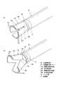
図3は、内視鏡先端カバー70の構成を示す説明図である。図3(A)の通常状態(閉状態)の斜視図に示すように、内視鏡先端カバー70は、主に、先端構成部30に装着される装着部77と、該装着部77の図3では上部に示される剥離対象側連結部73Aで連結されている剥離対象支持部72Aと、装着部77の図3では下部に示される本体側連結部73Bで連結されている本体側当接部72Bと、剥離対象支持部72Aと本体側当接部72Bとをリンクするリンク部74とを有しており、透明の樹脂部材によって一体形成されている。この樹脂部材は、可撓性素材で、かつ弾性を有するように形成されている。 FIG. 3 is an explanatory diagram showing the configuration of the endoscope
装着部77は、リング状に形成されており、内径R1が先端構成部30の先端の外形R2と同一か僅かに小さい大きさに形成されている。これにより、装着部77の素材自身の弾性力を生かして装着部77を先端構成部30の先端に押し込み、装着部77の内径R1が僅かに拡径し両者を嵌め合わせることで、装着部77をしっかり取り付けることができ、先端構成部30から簡単に外れないようにしている。なお、装着部77は、本実施例ではリング状の閉じた形状をなすが、一部が開いた馬蹄形状であってもよい。少なくとも、施術時など内視鏡使用中に、先端構成部30と装着部77とが堅固に装着されていればよい。 The mounting
剥離対象支持部72Aは、円筒形を半分に縦断した断面円弧形状で上方が凸に形成されている。この剥離対象支持部72Aの先端側外周には、外側へ凸となる剥離対象側凸部71Aが複数横並びに配置されている。また、剥離対象支持部72Aの基部側は、剥離対象側連結部73Aにより装着部77に連結されている。 72 A of peeling object support parts are formed in the cross-section circular arc shape which cut the cylinder shape in half, and the upper part is convexly formed. A plurality of separation target side
本体側当接部72Bは、円筒形を半分に縦断した断面円弧形状で下方が凸に形成されている。この本体側当接部72Bの先端側外周には、外側へ凸となる本体側凸部71Bが複数横並びに配置されている。また、本体側当接部72Bの基部側は、本体側連結部73Bにより装着部77に連結されている。 The main body
リンク部74は、剥離対象支持部72Aと本体側当接部72Bが基部側で連結されている部位により構成されている。
なお、剥離対象側凸部および本体側凸部は、本実施例では、それぞれ剥離対象支持部72Aの先端側外周と本体側当接部72Bの先端側外周とに配置されているが、この形態に限らず、例えば、剥離対象側凸部については、剥離対象支持部72Aの先端側を上方(開方向)へ少し捲り上げた口唇形状に形成し、該口唇形状の先端側内周に、外側へ凸となるように剥離対象側凸部を設けることも可能である。本体側凸部も同様に、本体側当接部72Bの先端側を下方(開方向)へ少し捲り上げた口唇形状に形成し、該口唇形状の先端側内周に、外側へ凸となるように剥離対象側凸部を設けることも可能である。The
In this embodiment, the peeling target side convex portion and the main body side convex portion are arranged on the distal end side outer periphery of the peeling
この剥離対象側凸部および本体側凸部は、少なくとも、剥離対象側の組織と本体側の組織とを効率よく押し広げられる構成であればよい。すなわち、内視鏡先端カバーが開動する際に、剥離対象側あるいは本体側の前記凸部が、剥離対象の組織(実施例では剥離部Hに相当)あるいは本体の組織(実施例では粘膜下層L2に相当)に当接され滑り止めの役割を果たすことができればよい。 The peeling target side convex portion and the main body side convex portion may be configured to efficiently spread at least the tissue on the peeling target side and the tissue on the main body side. That is, when the endoscope distal end cover is opened, the protrusion on the peeling target side or the main body side is the tissue to be peeled (corresponding to the peeling portion H in the embodiment) or the tissue of the main body (the submucosa L2 in the embodiment). It is only necessary to be able to play a role of anti-slip.
このように剥離対象側の組織と本体側の組織とを効率よく押し広げる構成により、滑り止め効果を発揮して、当接する組織に対して内視鏡先端カバーをしっかりと位置決めしながら該カバーの開動を容易にすることができ、また、押しのけた剥離対象が内視鏡先端カバーに凭れ掛かる場合に該カバーから剥離対象がズレ落ちて剥離作業を妨害することを防止でき、施術効率を向上させることができる。 In this way, the structure that efficiently spreads the tissue on the peeling target side and the tissue on the main body side exhibits an anti-slip effect, and firmly positions the endoscope distal end cover with respect to the abutting tissue. Opening can be facilitated, and when the peeled object to be pushed falls on the endoscope tip cover, it can be prevented that the peeled object slips from the cover and interferes with the peeling work, thereby improving the treatment efficiency. be able to.
図3(B)は、開状態の内視鏡先端カバー70の斜視図である。
本体側連結部73Bを回動軸として本体側凸部71Bが下方(開方向)へ移動するように本体側当接部72Bが回動されると、リンク部74は装着部77から離れるように先端側へ移動する。FIG. 3B is a perspective view of the endoscope
When the main body
そして、リンク部74は装着部77から離れるように先端側へ移動すると、剥離対象側連結部73Aを回動軸として剥離対象側凸部71Aが上方(開方項)へ移動するように剥離対象支持部72Aが回動する。 Then, when the
このように、内視鏡先端カバー70は、剥離対象支持部72Aと本体側当接部72Bが先端の開口を大きくするように開いた開状態(図3(B))と、剥離対象支持部72Aと本体側当接部72Bが先端の開口を小さくするように閉じた閉状態(図3(A))とに変位する。 As described above, the endoscope
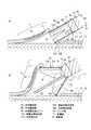
図4は、内視鏡装置10を用いて施術する際に内視鏡先端カバー70を開状態へ移行させる動作を示す説明図である。図示では、鉗子挿入口20(図1参照)に中空導波路60を挿入してレーザ光により粘膜層L1を切開剥離する粘膜下層切開剥離術(ESD)での使用方法を示している。なお、施術対象の本体部は、表面から順に粘膜層L1、粘膜下層L2、筋層L3を有する多層構造となっている。 FIG. 4 is an explanatory diagram illustrating an operation of moving the endoscope
図4(A)に示すように、腫瘍C1の周囲の粘膜層L1をレーザ光によってある程度切開し剥離している状態で、術者は、上下アングルノブ16や左右アングルノブ17を操作したり内視鏡を進退したりして内視鏡先端構成部30の位置を調整して剥離部Hを内視鏡先端カバー70で持ち上げる。このとき、内視鏡先端カバー70の剥離対象支持部72Aには、先端外周に剥離対象側凸部71Aが設けられているため、滑り止め機能が発揮されて内視鏡先端カバー70に設けられた凸部71A,71Bが剥離部Hを含む粘膜層L1と粘膜下層L2の組織に引っかかり、その結果、内視鏡先端カバー70が開動し剥離部Hを容易に持ち上げることができる。 As shown in FIG. 4 (A), the operator operates the up / down
そして、術者は、本体側当接部72Bの本体側凸部71Bを施術対象の本体側(図示の例では粘膜下層L2)に当接させる。このとき、本体側凸部71Bが滑り止め機能を発揮し、本体側凸部71Bが粘膜下層L2の当接部位にしっかりと位置決めされる。 Then, the operator brings the main body side
この状態で、図4(B)の矢印Yに示すように、術者が先端構成部30を先端側斜め上方(挿入方向から剥離対象支持部72A側へ斜め方向)へ押し込むと、本体側当接部72Bが下方へ開き、これに連動して剥離対象支持部72Aが上方へ開く。これにより、内視鏡先端カバー70の先端の開口が広がり、剥離部Hに対して持ち上げる方向へ張力をかけることができ、剥離部Hを大きく持ち上げることができる。 In this state, as shown by an arrow Y in FIG. 4B, when the surgeon pushes the distal
従って、当接する組織に対して内視鏡先端カバー70をしっかりと位置決めしながら該カバー70の開動を容易にすることができ、また、押しのけた剥離部Hが内視鏡先端カバー70に凭れ掛かる場合に該カバー70から剥離部Hがズレ落ちて剥離作業を妨害することを防止でき、施術効率を向上させることができる。 Accordingly, it is possible to facilitate the opening of the
このようにして、図4(B)に図示するように施術対象部位を広げて施術しやすい状態にでき、粘膜層L1と粘膜下層L2との間で切開が完了していない部位に中空導波路60からレーザ光を照射して切開および剥離を完了させることができる。
このとき、切開が完了していない部位は、内視鏡先端カバー70によって剥離部Hに対して持ち上げる方向へ張力をかけられているので組織が緊張状態にあり、このため切開がし易い環境となっているので剥離作業の効率がよいという利点が認められる。In this way, as shown in FIG. 4 (B), the site to be treated can be widened to be easily treated, and a hollow waveguide can be formed at the site where the incision has not been completed between the mucosa layer L1 and the submucosa L2. Incision and peeling can be completed by irradiating laser light from 60.
At this time, the site where the incision has not been completed is tensioned in the direction of lifting with respect to the peeling portion H by the endoscope
また、内視鏡チューブ21を体内から取り出すときや施術中に最適なポジションにするために内視鏡先端部30の位置を調整するときなどは、図4(B)に示す状態から図4(A)に示す状態へと逆順の操作を行うことで、内視鏡先端カバー70を閉状態にすることができる。すなわち、本体側凸部71Bが施術対象の本体側である粘膜下層L2に当接している状態で先端構成部30を矢印Yの逆方向である基部側下方へ斜めに引くと、本体側当接部72Bが閉方向へ回動してリンク部74が装着部77に当接するまで変位する。このリンク部74の移動に伴って剥離対象支持部72Aも回動し、内視鏡先端カバー70が閉状態となる。 Further, when the
このとき、凸部71A,71Bを形成する素材を、内視鏡先端カバー70を開状態へ移行させる動作時には当接する組織に対して抵抗力があり、内視鏡先端カバー70を閉状態へ移行させる動作時には、当接する組織に抗わないように撓む構成とすることが好適である。後述の凸部81A,81B,91A,91B,101A,101Bの構成についても凸部71A,71Bと同様のことがいえる。 At this time, the material forming the
以上の構成により、レーザ光による組織の剥離術に適した内視鏡先端カバー70を提供することができる。すなわち、施術対象の本体と剥離部Hの間に内視鏡先端カバー70を位置させて本体側当接部72Bおよび剥離対象支持部72Aを開くことで、施術対象の本体と剥離部Hを押しのけることができ、レーザ光を照射する部位を明瞭に露出させることができる。 With the above configuration, it is possible to provide the endoscope front end cover 70 suitable for tissue detachment using laser light. That is, the endoscope
さらに、施術対象の本体と剥離対象とを互いに剥離する方向へ外力を加えることにより、両者間の切開が完了していない組織を緊張させ、切開し易い状態とし剥離作業効率を上げることができる。 Furthermore, by applying an external force in a direction in which the main body to be treated and the object to be peeled are peeled from each other, the tissue that has not been incised between the two is tensioned, making it easy to incision and improving the work efficiency.
また、剥離対象側凸部71Aを設けたことにより、押しのけた剥離部Hが内視鏡先端カバー70に凭れ掛かる場合に該カバー70から剥離部Hが滑り落ちることを防止でき、施術効率を向上させることができる。また、本体側凸部71Bを設けたことにより、本体側の組織となる粘膜下層L2にしっかりと位置決めできるため、内視鏡先端カバー70の開閉動作を容易に行うことができる。特に、剥離部Hを押しのけた状態で、中空導波路60から照射するレーザ光57aの照射位置を微調整するべく湾曲管部23を湾曲動作等させた場合にも、上述した剥離部Hの滑り落ち防止機能と粘膜下層L2への固定機能により、剥離部Hを押しのけた状態を維持して効率よく施術を行うことができる。 Further, by providing the peeling target side
また、図4では描写を省略しているが、一般的にESDの施術において、切開剥離する腫瘍C1の周辺の粘膜下層L2の下方には、生理食塩水やヒアルロン酸(例えばムコアップ(登録商標))など、人体に影響を与えない液体(不図示)を注入する。これにより、切開する部分を隆起させ、切開しやすいようにする。また、これにより、レーザ光照射時には、注入した前記液体に照射されたレーザ光が吸収され、エネルギーが消費されるので、前記液体が防壁として機能し、粘膜下層L2の深層にある筋層L3を傷つけることを防止できるようにする。 Although illustration is omitted in FIG. 4, generally, in an ESD operation, physiological saline or hyaluronic acid (for example, Muco Up (registered trademark)) is located below the submucosa L2 around the tumor C1 to be incised and detached. Inject liquid (not shown) that does not affect the human body. Thereby, the part to be incised is raised so that the incision is easy. This also absorbs the laser light applied to the injected liquid and consumes energy during the laser light irradiation, so that the liquid functions as a barrier, and the muscle layer L3 in the deep layer of the submucosa L2 Help prevent injury.
上記の施術環境にあって、液体によって隆起され形態が安定しない粘膜下層L2の組織が、施術時に術野、視野の確保の妨げになる等の不都合になることがある。本発明の内視鏡先端カバー70の構成では、本体側当接部72Bが開方向に変位することによって、本体側凸部71Bおよび本体側当接部72Bが粘膜下層L2を押しのけるので、広い術野、視野を確保することができる。 In the above-described surgical environment, the tissue of the submucosa L2 that is raised by the liquid and whose form is not stable may be inconvenient, such as obstructing the securing of the surgical field and visual field during the surgical operation. In the configuration of the endoscope
また、剥離対象支持部72Aと本体側当接部72Bと装着部77を一体形成したことにより、内視鏡先端カバー70の部品点数を減らすことができる。従って、コストダウンを図ることができ、また、体内での部品の抜け落ちを防止することができる。 In addition, since the separation
また、内視鏡チューブ21を体内から取り出す際には、内視鏡先端カバー70を閉状態へ戻すことができるため、内視鏡先端カバー70が体内組織を傷つけることなく内視鏡先端カバー70付きの内視鏡チューブ21を体内から取り出すことができる。 Further, when the
また、内視鏡先端カバー70は透明であるため、広く明瞭な視野を確保することができる。 Moreover, since the endoscope
また、この内視鏡先端カバー70を先端構成部30に装着することで、レーザ光による組織の剥離術に適した内視鏡装置10を提供することができる。 In addition, by attaching the endoscope
また、内視鏡先端カバー70が可撓性の素材で形成されているため、柔軟に変形して開状態と閉状態に状態変位することができる。また、内視鏡先端カバー70がある程度の硬さを有していることで、剥離部Hを剥離対象支持部72Aによりしっかりと持ち上げることができる。 Moreover, since the endoscope
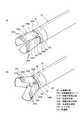
図5は、実施例2の内視鏡先端カバー80の構成を説明する説明図である。図5(A)の通常状態(閉状態)の斜視図に示すように、実施例2の内視鏡先端カバー80は、主に、先端構成部30に装着される装着部87と、該装着部87の上部に剥離対象側連結部83Aで連結されている剥離対象支持部82Aと、装着部87の下部に本体側連結部83Bで連結されている本体側当接部82Bとを有しており、透明の樹脂部材によって一体形成されている。また、剥離対象支持部82Aと本体側当接部82Bは、ヒンジ部84により相対回転可能に接続されている。 FIG. 5 is an explanatory diagram illustrating the configuration of the endoscope
装着部87は、リング状に形成されており、内径が先端構成部30の先端の外形と同一か僅かに小さい大きさに形成されている。これにより、装着部87を先端構成部30の先端にしっかり取り付けることができ、簡単には外れないようにしている。 The mounting
剥離対象支持部82Aは、円筒形を半分に縦断した断面円弧形状で上方が凸に形成されている。この剥離対象支持部82Aの先端側外周には、外側へ凸となる剥離対象側凸部81Aが複数横並びに配置されている。また、剥離対象支持部82Aの基部側は、剥離対象側連結部83Aにより装着部87に連結されている。 The peeling
本体側当接部82Bは、円筒形を半分に縦断した断面円弧形状で下方が凸に形成されている。この本体側当接部82Bの先端側外周には、外側へ凸となる本体側凸部81Bが複数横並びに配置されている。また、本体側当接部82Bの基部側は、本体側連結部83Bにより装着部87に連結されている。 The main body
上述した剥離対象側凸部81Aおよび本体側凸部81Bは、粘膜等の体内組織を傷つけない軟らかさでしなやかな素材により形成されている。この剥離対象側凸部81Aおよび本体側凸部81Bは、剥離対象支持部82Aおよび本体側当接部82Bにそれぞれ融着等によって固着されている。 The above-described peeling target side
ヒンジ部84は、剥離対象支持部82Aと本体側当接部82Bが基部側で重なり合っている部分を貫通して剥離対象支持部82Aと本体側当接部82Bとを連結している。このヒンジ部84は、他の部位と同じ素材で形成されている。なお、ヒンジ部84は、他の樹脂やゴムや金属など適宜の素材によって形成してもよい。 The
図5(B)は、開状態の内視鏡先端カバー80の斜視図である。
本体側連結部83Bを回動軸として本体側凸部81Bが下方(開方向)へ移動するように本体側当接部82Bが回動されると、ヒンジ部84は装着部87から離れるように先端側へ移動する。FIG. 5B is a perspective view of the endoscope front end cover 80 in the open state.
When the main body
そして、ヒンジ部84は装着部87から離れるように先端側へ移動すると、剥離対象側連結部83Aを回動軸として剥離対象側凸部81Aが上方(開方項)へ移動するように剥離対象支持部82Aが回動する。 Then, when the
このように、内視鏡先端カバー80は、剥離対象支持部82Aと本体側当接部82Bが先端の開口を大きくするように開いた開状態(図5(B))と、剥離対象支持部82Aと本体側当接部82Bが先端の開口を小さくするように閉じた閉状態(図5(A))とに変位する。 In this way, the endoscope
以上の構成により、実施例1と同一の効果を奏することができる。また、リンク部74の代わりにヒンジ部84を備えたことにより、剥離対象支持部82Aと本体側当接部82Bの相対回転をより良好に軽い力で実行することができる。 With the above configuration, the same effect as in the first embodiment can be obtained. Moreover, by providing the
図6は、実施例3の内視鏡先端カバー90の構成を説明する説明図である。図6(A)の通常状態(閉状態)の斜視図に示すように、実施例3の内視鏡先端カバー90は、主に、先端構成部30に装着される装着部97と、該装着部97の上部に剥離対象側連結部93Aで連結されている剥離対象支持部92Aと、装着部97の下部に本体側連結部93Bで連結されている本体側当接部92Bとを有しており、透明の樹脂部材によって一体形成されている。また、剥離対象支持部92Aと本体側当接部92Bは、ヒンジ部94により相対回転可能に接続されている。 FIG. 6 is an explanatory diagram illustrating the configuration of the endoscope
これらの剥離対象支持部92A、剥離対象側連結部93A、本体側当接部92B、本体側連結部93B、装着部97、およびヒンジ部94は、上述した実施例2の剥離対象支持部82A、剥離対象側連結部83A、本体側当接部82B、本体側連結部83B、装着部87、およびヒンジ部84と同一であるため、その詳細な説明を省略する。 The peeling
剥離対象支持部92Aの先端側の外周には、剥離対象側凸部91Aが複数設けられている。この剥離対象側凸部91Aは、先端側から基部側へ向かって突出する凸部である。 A plurality of separation target-side
同様に、本体側当接部92Bの先端側の外周には、本体側凸部91Bが複数設けられている。この本体側凸部91Bは、先端側から基部側へ向かって突出する凸部である。 Similarly, a plurality of main body side
剥離対象支持部92Aと本体側当接部92Bとの基部側での重なり部分には、バネ95が設けられている。このバネ95は、剥離対象支持部92Aと本体側当接部92Bを互いに広げる方向へ常に付勢している。従って、図6(B)に示すように開状態へ移行する際に、ある程度押し込めばバネ95の付勢力によって内視鏡先端カバー90を一気に最大限開くことができる。 A
このように構成した実施例3も、実施例1,2と同一の作用効果を得ることができる。この実施例3の内視鏡先端カバー70は、実施例2に加えてさらにバネ95を備えたことにより、剥離部Hと本体との間をより容易かつ適切に最大限開くことができきる。 The third embodiment configured as described above can also obtain the same operational effects as the first and second embodiments. In addition to the second embodiment, the endoscope front end cover 70 according to the third embodiment can further open the gap between the peeling portion H and the main body more easily and appropriately by further including a
図7は、実施例4の内視鏡先端カバー100の構成を説明する説明図である。図7(A)の通常状態(閉状態)の斜視図に示すように、実施例4の内視鏡先端カバー100は、主に、先端構成部30に装着される装着部107と、該装着部107の先端側上部側に配置される剥離対象支持部102Aと、装着部107の先端側下部側に配置される本体側当接部102Bとを有しており、それぞれ透明の樹脂部材によって別体に形成されている。 FIG. 7 is an explanatory diagram illustrating the configuration of the endoscope
装着部107の左右先端側には、先端側へ突出する支持アーム108が左右対称に設けられている。そして、この支持アーム108と、剥離対象支持部102Aと本体側当接部102Bとが重なり合っている部分にヒンジ部104が設けられている。このヒンジ部104により、支持アーム108を中心にして剥離対象支持部102Aと本体側当接部102Bとが相対的に回転可能に取り付けられている。 On the left and right tip sides of the mounting
剥離対象支持部102Aの基部側は、上端より下端側が基部側へ凸となるよう傾斜する切り欠き部106Aが設けられている。また、本体側当接部102Bの基部側は、下端より上端側が基部側へ凸となるよう傾斜する切り欠き部106Bが設けられている。この切り欠き部106A,106Bにより、剥離対象支持部102Aと本体側当接部102Bがそれぞれ開方向へ回動しても、剥離対象支持部102Aと本体側当接部102Bが内視鏡チューブ21や先端構成部30等を圧迫しないようにしている。 On the base side of the separation
その他の構成は、実施例3のバネ95が無い点を除けば実施例3と同一であるため、その詳細な説明を省略する。
以上の構成により、実施例3と同一の作用効果を得ることができる。切り欠き部106A,106Bを設けたことにより、剥離対象支持部102Aと本体側当接部102Bが内視鏡チューブ21や先端構成部30等を圧迫することがなく、良好に動作することができる。Since the other configuration is the same as that of the third embodiment except that the
With the above configuration, it is possible to obtain the same effect as that of the third embodiment. By providing the
なお、切り欠き部106A,106Bの替わりに、内視鏡先端カバー100が開動作するときに当接し合う、剥離対象支持部102Aおよび本体側当接部102Bと支持アーム108とのうち少なくともいずれか一方の当接箇所を弾性部材にすることで、他方にかかる圧力を吸収できる構成にしてもよい。 Instead of the
また、内視鏡先端カバー70,80,90,100を形成する素材は、透明の樹脂部材に限らず、ゴム素材とする、あるいは金属素材とするなど、適宜の素材により形成することができる。この場合も、可撓性を有する素材とすることが好ましく、弾性を有する素材であることがさらに好ましい。 The material forming the endoscope distal end covers 70, 80, 90, 100 is not limited to a transparent resin member, and may be formed of an appropriate material such as a rubber material or a metal material. Also in this case, it is preferable to use a flexible material, and it is more preferable to use an elastic material.
また、内視鏡先端カバー70,80,90,100は、透明に限らず、半透明の素材により形成してもよい。この場合でも内視鏡先端カバー70,80,90,100を透過した広い視野を確保することができる。 Further, the endoscope tip covers 70, 80, 90, 100 are not limited to being transparent, and may be formed of a translucent material. Even in this case, it is possible to ensure a wide field of view through the endoscope distal end covers 70, 80, 90, 100.
さらに、内視鏡先端カバーの形状について、以上の実施例では、剥離対象支持部と本体側当接部が円筒形を半分に縦断した断面円弧形状である場合を挙げたが、この形状に限定されるものではなく、例えば、内視鏡先端部30に装着される一端は内視鏡先端部30と同形状の円形をなし、使用時に開閉運動する開口側の他端は、楕円形や四角形や多角形をなしていてもよい。少なくとも、使用中に抜け落ちることがなく、開口運動を行うことが可能で、レーザ光57aを照射する部位を明瞭に露出させることができ、術野および視野の確保が可能であればよい。 Further, regarding the shape of the endoscope front end cover, in the above embodiment, the case where the separation target support portion and the main body side contact portion have a circular arc shape in which the cylindrical shape is cut in half has been mentioned, but the shape is limited to this shape. For example, one end attached to the endoscope
この発明の構成と、上述の実施形態との対応において、
この発明の内視鏡レーザ治療装置は、実施形態の治療システム1に対応し、
以下同様に、
内視鏡は、内視鏡装置10に対応し、
レーザ照射手段は、レーザ発振部57に対応し、
治療用レーザ光は、レーザ光57aに対応し、
導光路は、中空導波路60に対応し、
連関部は、リンク部74およびヒンジ部84,94,104に対応し、
付勢手段は、バネ95に対応し、
剥離対象は、剥離部Hに対応するが、
この発明は、上述の実施形態の構成のみに限定されるものではなく、多くの実施の形態を得ることができる。In correspondence between the configuration of the present invention and the above-described embodiment,
The endoscope laser treatment apparatus of the present invention corresponds to the
Similarly,
The endoscope corresponds to the
The laser irradiation means corresponds to the
The therapeutic laser beam corresponds to the
The light guide corresponds to the
The associating portion corresponds to the
The biasing means corresponds to the
The peeling target corresponds to the peeling portion H,
The present invention is not limited only to the configuration of the above-described embodiment, and many embodiments can be obtained.
この発明は、内視鏡の先端構成部に装着して用いることができ、内視鏡を用いた様々な治療・施術や観察に用いることができる。
以上述べてきた本発明の内視鏡先端カバーは、レーザ治療装置を備える内視鏡に特に有効なものであるが、従来のような、治療用デバイスとして高周波メス、電気メスなどを備えた内視鏡にも、汎用することができる。The present invention can be used by being attached to the distal end configuration portion of an endoscope, and can be used for various treatments / treatments and observations using the endoscope.
The endoscope distal end cover of the present invention described above is particularly effective for an endoscope having a laser treatment apparatus. However, an endoscope provided with a high-frequency knife, an electric knife, or the like as a conventional treatment device. It can also be used for endoscopes.
1…治療システム、10…内視鏡装置、13…操作部、21…内視鏡チューブ、30…先端構成部、45…撮像部、50…レーザ治療装置、57…レーザ発振部、57a…レーザ光、60…中空導波路、70…内視鏡先端カバー、71A,81A,91A,101A…剥離対象側凸部、71B,81B,91B,101B…本体側凸部、72A,82A,92A,102A…剥離対象支持部、72B,82B,92B,102B…本体側当接部、74…リンク部、77,87,97,107…装着部、84,94,104…ヒンジ部、95…バネ、H…剥離部DESCRIPTION OF
Claims (8)
Translated fromJapanese前記内視鏡チューブの先端構成部に装着する装着部と、
施術対象の本体に前記装着部より先端側の位置で当接する本体側当接部と、
前記施術対象から剥離する剥離対象を前記装着部より先端側の位置で持ち上げる剥離対象支持部と、
前記本体側当接部と前記剥離対象支持部とを略同時に開閉運動させる連関部とを備えた
内視鏡先端カバー。An endoscope tip cover attached to the tip constituent part of the endoscope tube,
A mounting portion to be mounted on a distal end configuration portion of the endoscope tube;
A main body side abutting portion that abuts the main body to be treated at a position on the tip side from the mounting portion;
A peeling target support part that lifts a peeling target to be peeled off from the treatment target at a position on the tip side from the mounting part;
An endoscope distal end cover including an associating portion that opens and closes the main body side contact portion and the separation target support portion substantially simultaneously.
少なくとも前記本体側当接部が前記施術対象の本体側に当接した状態にあるか、もしくは前記剥離対象支持部が前記剥離対象を支持した状態で、
前進移動されると前記本体側当接部と前記剥離対象支持部とを開動し、
後退移動されると前記本体側当接部と前記剥離対象支持部とを閉動する
請求項1記載の内視鏡先端カバー。The linkage is
In a state where at least the main body side contact portion is in contact with the main body side of the treatment target, or in a state where the separation target support portion supports the separation target,
When moved forward, the main body side contact portion and the separation target support portion are opened,
The endoscope front end cover according to claim 1, wherein when the body is moved backward, the main body side contact portion and the separation target support portion are closed.
前記剥離対象支持部の先端側外周部に、前記剥離対象を支持し且つ剥離対象側方向へ凸となる剥離対象側凸部を備えた
請求項1または2に記載の内視鏡先端カバー。Provided on the outer peripheral portion on the distal end side of the main body side contact portion is a main body side convex portion that comes into contact with the main body side of the treatment target and is convex in the main body side direction,
The endoscope distal end cover according to claim 1 or 2, further comprising a separation target side convex portion that supports the separation target and is convex in a separation target side direction on a distal end side outer peripheral portion of the separation target support portion.
請求項1から3のいずれか1つに記載の内視鏡先端カバー。The internal view according to any one of claims 1 to 3, wherein the mounting portion, the main body side contact portion, the separation target support portion, and the linkage portion are integrally formed of a flexible material that is deformed by an external force. Mirror tip cover.
前記本体側当接部と前記剥離対象支持部とを相対回転可能に支持するヒンジ部材により形成した
請求項1から3のいずれか1つに記載の内視鏡先端カバー。The linkage part is
The endoscope front end cover according to any one of claims 1 to 3, wherein the endoscope front end cover is formed by a hinge member that supports the main body side contact portion and the separation target support portion so as to be relatively rotatable.
請求項1、3、または5記載の内視鏡先端カバー。The endoscope distal end cover according to claim 1, further comprising an urging unit that urges the main body side contact portion and the separation target support portion in an opening direction or a closing direction.
該内視鏡チューブの先端側に設けられる先端構成部と、
該先端構成部に装着される請求項1から6のいずれか1つに記載の内視鏡先端カバーと、
前記先端構成部を湾曲動作させる操作部と、
前記先端構成部から施術対象を撮像する撮像部とを備え、
前記内視鏡先端カバーは、前記装着部が前記先端構成部に対して着脱自在である
内視鏡。A bendable endoscope tube;
A distal-end component provided on the distal end side of the endoscope tube;
The endoscope distal end cover according to any one of claims 1 to 6, which is attached to the distal end configuration part;
An operation section for bending the tip constituting section;
An imaging unit that images the treatment target from the tip component part,
The endoscope distal end cover is an endoscope in which the mounting portion is detachable from the distal end configuration portion.
治療用レーザ光を照射するレーザ照射手段および前記内視鏡の前記内視鏡チューブに挿通されて前記治療用レーザ光を導光する導光路を有するレーザ治療装置とを更に備えた
内視鏡レーザ治療装置。An endoscope according to claim 7;
An endoscope laser further comprising: laser irradiation means for irradiating treatment laser light; and a laser treatment apparatus having a light guide path that is inserted through the endoscope tube of the endoscope and guides the treatment laser light. Therapeutic device.
Priority Applications (1)
| Application Number | Priority Date | Filing Date | Title |
|---|---|---|---|
| JP2010182581AJP5431270B2 (en) | 2010-08-17 | 2010-08-17 | Endoscope tip cover and endoscope |
Applications Claiming Priority (1)
| Application Number | Priority Date | Filing Date | Title |
|---|---|---|---|
| JP2010182581AJP5431270B2 (en) | 2010-08-17 | 2010-08-17 | Endoscope tip cover and endoscope |
Publications (2)
| Publication Number | Publication Date |
|---|---|
| JP2012040108A JP2012040108A (en) | 2012-03-01 |
| JP5431270B2true JP5431270B2 (en) | 2014-03-05 |
Family
ID=45897097
Family Applications (1)
| Application Number | Title | Priority Date | Filing Date |
|---|---|---|---|
| JP2010182581AActiveJP5431270B2 (en) | 2010-08-17 | 2010-08-17 | Endoscope tip cover and endoscope |
Country Status (1)
| Country | Link |
|---|---|
| JP (1) | JP5431270B2 (en) |
Cited By (1)
| Publication number | Priority date | Publication date | Assignee | Title |
|---|---|---|---|---|
| KR20200012515A (en)* | 2018-07-27 | 2020-02-05 | (주) 엠아이원 | Apparatus for assisting endoscope |
Families Citing this family (11)
| Publication number | Priority date | Publication date | Assignee | Title |
|---|---|---|---|---|
| JP5975257B2 (en)* | 2012-03-08 | 2016-08-23 | 国立大学法人 香川大学 | Area securing instrument and endoscope provided with area securing instrument |
| JP5918577B2 (en)* | 2012-03-08 | 2016-05-18 | 株式会社リバーセイコー | Body cavity observation visual field securing device |
| CN102697443B (en)* | 2012-04-24 | 2014-10-08 | 王东 | Endoscope provided with protective casings on end actuator |
| JP5792416B1 (en)* | 2013-11-01 | 2015-10-14 | オリンパス株式会社 | Endoscopic treatment system |
| EP3138504B1 (en)* | 2014-05-02 | 2019-06-05 | Olympus Corporation | Mucous membrane elevation instrument for endoscope and endoscope treatment system |
| CN106455912B (en)* | 2014-05-02 | 2018-05-04 | 奥林巴斯株式会社 | Mucosa lifting device for endoscope and endoscope disposal system |
| JP6315379B2 (en)* | 2014-05-23 | 2018-04-25 | 株式会社トップ | Endoscope hood |
| US20170119234A1 (en)* | 2015-10-14 | 2017-05-04 | Cook Medical Technologies Llc | Endoscope cap with separable arms |
| CN108143445B (en)* | 2016-12-02 | 2024-02-23 | 天津市人民医院 | Gastroscope auxiliary stripping piece and pushing device thereof |
| KR102294046B1 (en)* | 2020-02-18 | 2021-08-25 | 가톨릭대학교 산학협력단 | Variable cap device for Endoscopic Submucosal Dissection |
| KR102567070B1 (en)* | 2021-04-22 | 2023-08-16 | 재단법인 아산사회복지재단 | LED-cap assisted endoscopic low-level laser therapy |
Family Cites Families (8)
| Publication number | Priority date | Publication date | Assignee | Title |
|---|---|---|---|---|
| JP3625883B2 (en)* | 1994-12-22 | 2005-03-02 | オリンパス株式会社 | Endoscope |
| JP2001275933A (en)* | 2000-03-31 | 2001-10-09 | Olympus Optical Co Ltd | Hood for endoscope |
| JP4413773B2 (en)* | 2002-05-17 | 2010-02-10 | エシコン・エンド−サージェリィ・インコーポレイテッド | Methods and devices for organizational reconfiguration |
| JP3806713B2 (en)* | 2003-10-06 | 2006-08-09 | オリンパス株式会社 | Endoscope hood and endoscope |
| JP4464721B2 (en)* | 2004-03-15 | 2010-05-19 | オリンパス株式会社 | Endoscope hood |
| CN101111200B (en)* | 2004-12-17 | 2010-05-12 | 国立大学法人京都大学 | Cap attachment and endoscope with cutting function |
| US7860555B2 (en)* | 2005-02-02 | 2010-12-28 | Voyage Medical, Inc. | Tissue visualization and manipulation system |
| JP5256491B2 (en)* | 2008-03-18 | 2013-08-07 | 学校法人立命館 | Endoscope device |
- 2010
- 2010-08-17JPJP2010182581Apatent/JP5431270B2/enactiveActive
Cited By (2)
| Publication number | Priority date | Publication date | Assignee | Title |
|---|---|---|---|---|
| KR20200012515A (en)* | 2018-07-27 | 2020-02-05 | (주) 엠아이원 | Apparatus for assisting endoscope |
| KR102168133B1 (en)* | 2018-07-27 | 2020-10-20 | (주) 엠아이원 | Apparatus for assisting endoscope |
Also Published As
| Publication number | Publication date |
|---|---|
| JP2012040108A (en) | 2012-03-01 |
Similar Documents
| Publication | Publication Date | Title |
|---|---|---|
| JP5431270B2 (en) | Endoscope tip cover and endoscope | |
| US20170224199A1 (en) | Method and apparatus for steerable, rotatable, microendoscope with tool for cutting, coagulating, desiccating and fulgurating tissue | |
| US6458074B1 (en) | Endoscope | |
| JP7000590B2 (en) | Operation method of heat invasion observation device, endoscope system, heat invasion observation system, heat invasion observation device | |
| EP2248472B1 (en) | Surgical instrument | |
| JP5226897B2 (en) | Rigid endoscope | |
| JP6084338B2 (en) | Endoscopic submucosal dissection device and endoscope system | |
| KR20170052664A (en) | Method and apparatus for sensing position between layers of an eye | |
| JP5159968B2 (en) | Endoscopic treatment tool | |
| US20160367311A1 (en) | Instrumentation with Embedded Imaging Systems | |
| JP6013625B2 (en) | Endoscopic mucosal lifting tool and endoscope treatment system | |
| JP5308741B2 (en) | Medical equipment | |
| JP2008093019A (en) | Reect scope | |
| JP2010523176A (en) | Endoscopic suction device for mucosal resection | |
| JP2009247550A (en) | Treatment tool for endoscope and endoscope | |
| JP5006591B2 (en) | Ultrasound endoscope | |
| JP5781363B2 (en) | Exterior tube, laser transmission path, laser treatment instrument | |
| JP5700398B2 (en) | Laser treatment apparatus and laser output control method | |
| JP4864603B2 (en) | Ultrasound endoscope | |
| JP2005118295A (en) | Surgical excision instrument and surgical treatment system | |
| JP5517828B2 (en) | Hollow waveguide and laser therapy device | |
| JP5784972B2 (en) | Exterior tube, laser transmission path, laser treatment instrument | |
| JP6846759B2 (en) | Laser chips, laser treatment tools, laser treatment equipment, and laser treatment systems | |
| JP4276832B2 (en) | Endoscope device | |
| JP2019076391A (en) | Laser chip, laser treatment instrument, laser treatment device and laser treatment system |
Legal Events
| Date | Code | Title | Description |
|---|---|---|---|
| A621 | Written request for application examination | Free format text:JAPANESE INTERMEDIATE CODE: A621 Effective date:20130329 | |
| A977 | Report on retrieval | Free format text:JAPANESE INTERMEDIATE CODE: A971007 Effective date:20131128 | |
| TRDD | Decision of grant or rejection written | ||
| A01 | Written decision to grant a patent or to grant a registration (utility model) | Free format text:JAPANESE INTERMEDIATE CODE: A01 Effective date:20131203 | |
| A61 | First payment of annual fees (during grant procedure) | Free format text:JAPANESE INTERMEDIATE CODE: A61 Effective date:20131204 | |
| R150 | Certificate of patent or registration of utility model | Free format text:JAPANESE INTERMEDIATE CODE: R150 Ref document number:5431270 Country of ref document:JP Free format text:JAPANESE INTERMEDIATE CODE: R150 | |
| R250 | Receipt of annual fees | Free format text:JAPANESE INTERMEDIATE CODE: R250 |