JP5430883B2 - Surgical stapling instrument with articulating end effector - Google Patents
Surgical stapling instrument with articulating end effectorDownload PDFInfo
- Publication number
- JP5430883B2 JP5430883B2JP2008161510AJP2008161510AJP5430883B2JP 5430883 B2JP5430883 B2JP 5430883B2JP 2008161510 AJP2008161510 AJP 2008161510AJP 2008161510 AJP2008161510 AJP 2008161510AJP 5430883 B2JP5430883 B2JP 5430883B2
- Authority
- JP
- Japan
- Prior art keywords
- surgical instrument
- end effector
- firing
- trigger
- tooth
- Prior art date
- Legal status (The legal status is an assumption and is not a legal conclusion. Google has not performed a legal analysis and makes no representation as to the accuracy of the status listed.)
- Active
Links
- 239000012636effectorSubstances0.000titleclaimsdescription184
- 230000007246mechanismEffects0.000claimsdescription93
- 230000002093peripheral effectEffects0.000claimsdescription45
- 230000033001locomotionEffects0.000claimsdescription30
- 238000000034methodMethods0.000claimsdescription16
- 230000008878couplingEffects0.000claimsdescription12
- 238000010168coupling processMethods0.000claimsdescription12
- 238000005859coupling reactionMethods0.000claimsdescription12
- 238000001356surgical procedureMethods0.000claimsdescription6
- 230000001954sterilising effectEffects0.000claimsdescription5
- 238000012545processingMethods0.000claimsdescription4
- 238000010304firingMethods0.000description180
- 210000004872soft tissueAnatomy0.000description38
- 238000005520cutting processMethods0.000description27
- 210000001519tissueAnatomy0.000description5
- 230000008901benefitEffects0.000description4
- 239000003795chemical substances by applicationSubstances0.000description4
- 230000003993interactionEffects0.000description3
- 239000000463materialSubstances0.000description3
- 230000005855radiationEffects0.000description3
- 230000003068static effectEffects0.000description3
- 208000027418Wounds and injuryDiseases0.000description2
- 230000008859changeEffects0.000description2
- 238000004140cleaningMethods0.000description2
- 230000000994depressogenic effectEffects0.000description2
- 230000000007visual effectEffects0.000description2
- 241000894006BacteriaSpecies0.000description1
- 239000004775TyvekSubstances0.000description1
- 229920000690TyvekPolymers0.000description1
- 230000006978adaptationEffects0.000description1
- 230000005540biological transmissionEffects0.000description1
- 230000000740bleeding effectEffects0.000description1
- 238000013461designMethods0.000description1
- 238000011161developmentMethods0.000description1
- 230000018109developmental processEffects0.000description1
- 238000006073displacement reactionMethods0.000description1
- 230000000694effectsEffects0.000description1
- 239000013013elastic materialSubstances0.000description1
- 230000006872improvementEffects0.000description1
- 208000014674injuryDiseases0.000description1
- 238000004519manufacturing processMethods0.000description1
- 238000012986modificationMethods0.000description1
- 230000004048modificationEffects0.000description1
- 238000005381potential energyMethods0.000description1
- 230000008569processEffects0.000description1
- 238000004659sterilization and disinfectionMethods0.000description1
- 230000017105transpositionEffects0.000description1
- 230000008733traumaEffects0.000description1
- 238000004804windingMethods0.000description1
Images


Classifications
- A—HUMAN NECESSITIES
- A61—MEDICAL OR VETERINARY SCIENCE; HYGIENE
- A61B—DIAGNOSIS; SURGERY; IDENTIFICATION
- A61B17/00—Surgical instruments, devices or methods
- A61B17/068—Surgical staplers, e.g. containing multiple staples or clamps
- A61B17/072—Surgical staplers, e.g. containing multiple staples or clamps for applying a row of staples in a single action, e.g. the staples being applied simultaneously
- A61B17/07207—Surgical staplers, e.g. containing multiple staples or clamps for applying a row of staples in a single action, e.g. the staples being applied simultaneously the staples being applied sequentially
- A—HUMAN NECESSITIES
- A61—MEDICAL OR VETERINARY SCIENCE; HYGIENE
- A61B—DIAGNOSIS; SURGERY; IDENTIFICATION
- A61B17/00—Surgical instruments, devices or methods
- A61B17/28—Surgical forceps
- A61B17/29—Forceps for use in minimally invasive surgery
- A61B17/2909—Handles
- A61B2017/2912—Handles transmission of forces to actuating rod or piston
- A61B2017/2913—Handles transmission of forces to actuating rod or piston cams or guiding means
- A61B2017/2916—Handles transmission of forces to actuating rod or piston cams or guiding means pins in guiding slots
- A—HUMAN NECESSITIES
- A61—MEDICAL OR VETERINARY SCIENCE; HYGIENE
- A61B—DIAGNOSIS; SURGERY; IDENTIFICATION
- A61B17/00—Surgical instruments, devices or methods
- A61B17/28—Surgical forceps
- A61B17/29—Forceps for use in minimally invasive surgery
- A61B17/2909—Handles
- A61B2017/2912—Handles transmission of forces to actuating rod or piston
- A61B2017/2923—Toothed members, e.g. rack and pinion
- A—HUMAN NECESSITIES
- A61—MEDICAL OR VETERINARY SCIENCE; HYGIENE
- A61B—DIAGNOSIS; SURGERY; IDENTIFICATION
- A61B17/00—Surgical instruments, devices or methods
- A61B17/28—Surgical forceps
- A61B17/29—Forceps for use in minimally invasive surgery
- A61B2017/2926—Details of heads or jaws
- A61B2017/2927—Details of heads or jaws the angular position of the head being adjustable with respect to the shaft
- A61B2017/2929—Details of heads or jaws the angular position of the head being adjustable with respect to the shaft with a head rotatable about the longitudinal axis of the shaft
- A—HUMAN NECESSITIES
- A61—MEDICAL OR VETERINARY SCIENCE; HYGIENE
- A61B—DIAGNOSIS; SURGERY; IDENTIFICATION
- A61B17/00—Surgical instruments, devices or methods
- A61B17/28—Surgical forceps
- A61B17/29—Forceps for use in minimally invasive surgery
- A61B2017/2926—Details of heads or jaws
- A61B2017/2932—Transmission of forces to jaw members
- A61B2017/2943—Toothed members, e.g. rack and pinion
- A—HUMAN NECESSITIES
- A61—MEDICAL OR VETERINARY SCIENCE; HYGIENE
- A61B—DIAGNOSIS; SURGERY; IDENTIFICATION
- A61B17/00—Surgical instruments, devices or methods
- A61B17/28—Surgical forceps
- A61B17/29—Forceps for use in minimally invasive surgery
- A61B2017/2946—Locking means
Landscapes
- Health & Medical Sciences (AREA)
- Life Sciences & Earth Sciences (AREA)
- Surgery (AREA)
- Heart & Thoracic Surgery (AREA)
- Engineering & Computer Science (AREA)
- Biomedical Technology (AREA)
- Nuclear Medicine, Radiotherapy & Molecular Imaging (AREA)
- Medical Informatics (AREA)
- Molecular Biology (AREA)
- Animal Behavior & Ethology (AREA)
- General Health & Medical Sciences (AREA)
- Public Health (AREA)
- Veterinary Medicine (AREA)
- Surgical Instruments (AREA)
Description
Translated fromJapanese〔背景〕
本願は、本願と同時出願された、所有者が共通の以下の米国特許出願に関連し、それら米国特許出願は、参照により全体として本明細書に組み込まれる。
(1)米国特許出願第11/821,425号(名称「END EFFECTOR CLOSURE SYSTEM FOR A SURGICAL STAPLING INSTRUMENT」、代理人整理番号:END6085USNP/070054);
(2)米国特許出願第11/821,426号(名称「SURGICAL STAPLING INSTRUMENT WITH AN ANTI-BACK UP MECHANISM」、代理人整理番号:END6100USNP/070053);
(3)米国特許出願第11/821,347号(名称「SURGICAL STAPLING INSTRUMENT WITH A RETURN MECHANISM」、代理人整理番号:END6091USNP/070061);および、
(4)米国特許出願第11/821,277号(名称「SURGICAL STAPLING INSTRUMENTS」、代理人整理番号:END6099USNP/070057)〔background〕
This application is related to the following commonly owned US patent applications filed concurrently with this application, which are hereby incorporated by reference in their entirety:
(1) US Patent Application No. 11 / 821,425 (named “END EFFECTOR CLOSURE SYSTEM FOR A SURGICAL STAPLING INSTRUMENT”, agent serial number: END 6085 USNP / 070054);
(2) US patent application Ser. No. 11 / 821,426 (name “SURGICAL STAPLING INSTRUMENT WITH AN ANTI-BACK UP MECHANISM”, agent serial number: END6100USNP / 070053);
(3) US patent application Ser. No. 11 / 821,347 (named “SURGICAL STAPLING INSTRUMENT WITH A RETURN MECHANISM”, agent reference number: END6091USNP / 070061);
(4) US Patent Application No. 11 / 821,277 (name “SURGICAL STAPLING INSTRUMENTS”, agent serial number: END 6099 USNP / 070057)
1.発明の分野
本発明は、概して外科用ステープル留め器具に関し、より詳細には、エンドエフェクタを閉じるための閉鎖システム、およびステープルを配備するための発射システムを有する、外科用ステープラに関する。1. The present invention relates generally to surgical stapling instruments, and more particularly to a surgical stapler having a closure system for closing an end effector and a firing system for deploying staples.
2.関連技術の説明
当技術分野で知られるように、外科用ステープラは、例えば軟組織が横に切開されているときに特に、軟組織からの出血を減らすか、または排除するために、軟組織の中にステープルを配備するのにしばしば用いられる。例えば、エンドカッターなどの外科用ステープラは、エンドエフェクタを含むことができ、このエンドエフェクタは、細長いシャフト組立体に対して動くか、または関節運動することができる。エンドエフェクタは多くの場合、第1のジョー部材と第2のジョー部材との間で軟組織を固定するように構成されており、第1のジョー部材は多くの場合、ステープルを取り外し可能に内部に保管するように構成されたステープルカートリッジを含み、第2のジョー部材は多くの場合、アンビルを含む。このような外科用ステープラは、ステープルカートリッジに対してアンビルを旋回させるための閉鎖システムを含むことができる。しかしながら、これらの閉鎖システムは、ジョー部材が閉じられた後でエンドエフェクタがシャフト組立体に対して関節運動することを妨げない。その結果、エンドエフェクタが関節運動すると、エンドエフェクタはジョー部材の間に捕捉された軟組織に剪断力を加える場合がある。2. 2. Description of Related Art As is known in the art, surgical staplers are typically stapled into soft tissue to reduce or eliminate bleeding from the soft tissue, particularly when the soft tissue is cut laterally. Often used to deploy For example, a surgical stapler, such as an end cutter, can include an end effector that can move or articulate relative to the elongate shaft assembly. The end effector is often configured to secure soft tissue between the first jaw member and the second jaw member, the first jaw member often having a staple removably disposed therein. Including a staple cartridge configured to be stored, the second jaw member often includes an anvil. Such a surgical stapler can include a closure system for pivoting the anvil relative to the staple cartridge. However, these closure systems do not prevent the end effector from articulating relative to the shaft assembly after the jaw members are closed. As a result, when the end effector articulates, the end effector may apply a shear force to the soft tissue captured between the jaw members.
前記に概略を述べたように、外科用ステープラは、アンビルとステープルカートリッジとの間に軟組織を捕捉するために、ステープルカートリッジに対してエンドエフェクタのアンビルを旋回させるように構成されることができる。様々な状況において、アンビルは、アンビルとステープルカートリッジとの間に軟組織をしっかりと保持するために、軟組織にクランプ力を加えるように構成されうる。しかしながら、外科医がエンドエフェクタの位置に満足しない場合、外科医は、通常、外科用ステープラの解除機構を作動させて、アンビルを開位置に旋回させ、次にエンドエフェクタを再度位置付けなければならない。その後、ステープルは通常、駆動体であって、ステープルカートリッジのチャネルを横切り、ステープルがアンビルに当たって変形し、かつ軟組織層を共に固定するようにする、駆動体により、ステープルカートリッジから配備される。当技術分野で知られているように、多くの場合、ステープルは、より確実に組織層を共に固定するために、いくつかのステープルラインすなわち列で配備される。エンドエフェクタは、例えばナイフなどの切断部材も含むことができ、この切断部材は、軟組織層が共にステープル留めされた後で、軟組織を切除するためにステープルの2つの列の間を前進させられる。 As outlined above, the surgical stapler can be configured to pivot the end effector anvil relative to the staple cartridge to capture soft tissue between the anvil and the staple cartridge. In various situations, the anvil can be configured to apply a clamping force to the soft tissue to securely hold the soft tissue between the anvil and the staple cartridge. However, if the surgeon is not satisfied with the position of the end effector, the surgeon typically must actuate the surgical stapler release mechanism to pivot the anvil to the open position and then reposition the end effector. Thereafter, the staple is typically a driver that is deployed from the staple cartridge by the driver that traverses the channels of the staple cartridge, causing the staples to strike and deform against the anvil and secure the soft tissue layer together. As is known in the art, in many cases, staples are deployed in several staple lines or rows to more secure the tissue layers together. The end effector can also include a cutting member, such as a knife, which is advanced between two rows of staples to cut the soft tissue after the soft tissue layers have been stapled together.
駆動体および切断部材がエンドエフェクタ内を前進させられた後、駆動体および/または切断部材をそれらの最初の位置(starting positions)まで後退させることが、多くの場合必要である。以前の外科用ステープラは、例えば、外科用ステープラの解除ボタンまたはトグルスイッチが外科医により作動された後でステープルカートリッジに対して切断部材を後退させる、戻しバネを含んでいた。様々な実施形態では、戻しバネの第1の端部は、外科用器具のハウジングに接続されてよく、このバネの第2の端部は、切断部材に接続されてよい。しかしながら、このようなステープラは、切断部材が前進させられるときに戻しバネを延ばすのに必要とされる力がしばしばかなり大きいので、多くの場合、使用するのが難しい。さらに、そのような戻しバネは、切断部材が前進させられるときに、切断部材にしばしば付勢力を加え、この戻しバネは、様々な状況において、切断部材を完全に前進させるためにトリガーの複数のストロークが必要とされる実施形態では特に、切断部材を早まって戻すことがある。必要とされるのは、前述のものに対する改善である。 After the driver and cutting member have been advanced through the end effector, it is often necessary to retract the driver and / or cutting member to their starting positions. Previous surgical staplers, for example, included a return spring that retracted the cutting member relative to the staple cartridge after the surgical stapler release button or toggle switch was actuated by the surgeon. In various embodiments, the first end of the return spring may be connected to the housing of the surgical instrument and the second end of the spring may be connected to the cutting member. However, such staplers are often difficult to use because the force required to extend the return spring when the cutting member is advanced is often quite large. In addition, such a return spring often applies a biasing force to the cutting member as the cutting member is advanced, and this return spring can be used in multiple situations to trigger the cutting member to fully advance. Particularly in embodiments where a stroke is required, the cutting member may be returned prematurely. What is needed is an improvement over the foregoing.
〔概要〕
本発明の少なくとも1つの形態では、外科用器具は、シャフト組立体と、シャフト組立体に対して動くことができるエンドエフェクタと、シャフト組立体とエンドエフェクタとの間の相対関係を固着するか、またはロックするためにシャフト組立体および/もしくはエンドエフェクタに係合するように構成されたロック機構と、を含むことができる。様々な実施形態では、エンドエフェクタは、アンビル、およびチャネルを含むことができ、チャネルは、ステープルカートリッジを受容するように構成されてよく、アンビルは、チャネルに可動に連結されてよい。少なくとも1つの実施形態において、外科用器具は、閉鎖運動を生じるように構成された閉鎖システムをさらに含むことができ、アンビルは、この閉鎖運動に応答することができる。様々な実施形態では、閉鎖システムは、ロック機構に係合し、かつロック機構がシャフト組立体とエンドエフェクタとの間の相対関係のロックを外すのを防ぐように、さらに構成されてよい。〔Overview〕
In at least one form of the invention, the surgical instrument secures the shaft assembly, the end effector movable relative to the shaft assembly, and the relative relationship between the shaft assembly and the end effector; Or a locking mechanism configured to engage the shaft assembly and / or the end effector for locking. In various embodiments, the end effector can include an anvil and a channel, the channel can be configured to receive a staple cartridge, and the anvil can be movably coupled to the channel. In at least one embodiment, the surgical instrument can further include a closure system configured to produce a closing motion, and the anvil can respond to the closing motion. In various embodiments, the closure system may be further configured to engage the locking mechanism and prevent the locking mechanism from unlocking the relative relationship between the shaft assembly and the end effector.
本発明の少なくとも1つの形態では、外科用器具は、例えば、開位置と、部分的に閉じた位置と、閉位置との間でエンドエフェクタのアンビルを動かすように構成された閉鎖システムを含むことができる。様々な実施形態では、外科用器具は、アンビルがその部分的に閉じた位置および閉位置のうちの一方に位置付けられたときに閉鎖システムに選択的に係合し、かつ閉鎖システムをロックするように構成された、ロック部材をさらに含むことができる。少なくとも1つの実施形態では、外科用器具は、例えばアンビルを旋回させるように構成されたトリガーを含んでよく、このトリガーは、カム面、およびそのカム面の第1のノッチを含むことができる。様々な実施形態では、ロック部材は、従動部分を含むことができ、閉鎖駆動装置(closure drive)は、トリガーのカム面に対して従動部分を付勢するように構成されたロックバネを含むことができ、そのため、従動部分は、アンビルがその部分的に閉じた位置に旋回されると、トリガーの第1のノッチに係合することができる。少なくとも1つの実施形態では、従動部分が第1のノッチと係合されると、第1のノッチは、アンビルがその開位置に旋回されることを防ぐことができる。様々な実施形態では、カム部分は、第2のノッチをさらに含むことができ、従動部分は、アンビルがその閉位置に旋回されると第2のノッチに係合するように構成されていてよい。 In at least one form of the invention, the surgical instrument includes a closure system configured to move an anvil of the end effector between, for example, an open position, a partially closed position, and a closed position. Can do. In various embodiments, the surgical instrument selectively engages and locks the closure system when the anvil is positioned in one of its partially closed and closed positions. The lock member may be further configured. In at least one embodiment, the surgical instrument may include a trigger configured to pivot the anvil, for example, and the trigger may include a cam surface and a first notch in the cam surface. In various embodiments, the locking member can include a driven portion, and the closure drive can include a lock spring configured to bias the driven portion against the cam surface of the trigger. The driven portion can then engage the first notch of the trigger when the anvil is pivoted to its partially closed position. In at least one embodiment, when the follower portion is engaged with the first notch, the first notch can prevent the anvil from being pivoted to its open position. In various embodiments, the cam portion can further include a second notch, and the follower portion can be configured to engage the second notch when the anvil is pivoted to its closed position. .
本発明の少なくとも1つの形態では、外科用器具は、例えば、エンドエフェクタ内で切断部材を前進させるように構成された、発射部材を含む発射駆動装置(firing drive)と、発射部材を後退させるように構成された、発射部材に接続された可撓性バンドと、を含むことができる。少なくとも1つの実施形態では、外科用器具は、例えば、バンドに係合するように構成された制動装置(brake)を含んでよく、これにより、発射部材の動きを制限することができる。様々な実施形態では、発射駆動装置は、発射部材が後退させられるとバンドの少なくとも一部を巻き上げるように構成されたリールをさらに含むことができる。少なくとも1つの実施形態では、発射駆動装置は、発射部材およびリールと選択的に係合可能なトリガーをさらに含むことができ、トリガーが発射部材と動作可能に係合されると、トリガーの作動は、発射部材を前進させるように構成されることができ、かつ、トリガーがリールと動作可能に係合されると、トリガーの作動は、リールを回転させ、かつバンドにより発射部材を後退させるように構成されうるようになっている。 In at least one form of the invention, the surgical instrument includes, for example, a firing drive including a firing member configured to advance the cutting member within the end effector, and to retract the firing member. And a flexible band connected to the firing member. In at least one embodiment, the surgical instrument may include, for example, a brake configured to engage the band, thereby limiting the movement of the firing member. In various embodiments, the firing drive can further include a reel configured to wind up at least a portion of the band when the firing member is retracted. In at least one embodiment, the firing drive can further include a trigger that is selectively engageable with the firing member and the reel, and when the trigger is operatively engaged with the firing member, actuation of the trigger is Can be configured to advance the firing member, and when the trigger is operably engaged with the reel, actuation of the trigger causes the reel to rotate and the firing member to be retracted by the band. It can be configured.
添付の図面と共に本発明の実施形態の以下の説明を参照することにより、本発明の前述の特徴および利点、他の特徴および利点、ならびに、それらを得る方法が、より明らかになるであろうし、また本発明そのものがよりよく理解されるであろう。 The foregoing features and advantages of the invention, other features and advantages, and methods for obtaining them will become more apparent from the following description of embodiments of the invention with reference to the accompanying drawings, The invention itself will also be better understood.
対応する参照符号は、いくつかの図面にわたって対応する部品を示している。本明細書に述べる例証は、1つの形態における本発明の好適な実施形態を示しており、このような例証は、いかなる方法によっても本発明の範囲を制限するものと解釈されるべきではない。 Corresponding reference characters indicate corresponding parts throughout the several views. The illustrations set forth herein illustrate preferred embodiments of the invention in one form, and such illustration should not be construed as limiting the scope of the invention in any way.
〔詳細な説明〕
本明細書に開示される装置および方法の構造、機能、製造、および使用の原理の総合的な理解をもたらすために、特定の例示的実施形態がこれから説明される。これらの実施形態の1つ以上の実施例が添付の図面に示されている。本明細書において特に説明され、かつ添付の図面に示される装置および方法は、非限定的な例示的実施形態であり、本発明の様々な実施形態の範囲は、特許請求の範囲によってのみ定められることを、当業者は理解するであろう。1つの例示的実施形態に関して示されるか、または説明される特徴部は、他の実施形態の特徴部と組み合わせられてよい。そのような修正および変形は、本発明の範囲内に含まれることを意図している。[Detailed explanation]
Certain exemplary embodiments will now be described to provide a comprehensive understanding of the principles of structure, function, manufacture, and use of the devices and methods disclosed herein. One or more examples of these embodiments are illustrated in the accompanying drawings. The devices and methods specifically described herein and illustrated in the accompanying drawings are non-limiting exemplary embodiments, and the scope of the various embodiments of the present invention is defined only by the claims. Those skilled in the art will understand that. Features shown or described with respect to one exemplary embodiment may be combined with features of other embodiments. Such modifications and variations are intended to be included within the scope of the present invention.
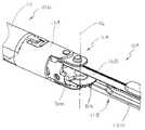
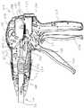
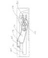
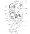
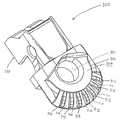
様々な実施形態では、本発明による外科用器具は、例えば、軟組織に外科用ステープルを挿入するように構成されることができる。少なくとも1つの実施形態では、図1〜図4を参照すると、外科用器具100は、ハンドル部分102と、細長いシャフト組立体104と、エンドエフェクタ106と、を含むことができる。様々な実施形態では、図3および図4を参照すると、エンドエフェクタ106は、ステープルカートリッジチャネル108、およびステープルカートリッジ110を含むことができ、ステープルカートリッジ110は、その中にステープルを取り外し可能に保管するように構成されうる。少なくとも1つの実施形態では、エンドエフェクタ106は、アンビル112をさらに含むことができ、このアンビル112は、ステープルカートリッジチャネル108に旋回可能に接続されてよく、かつエンドエフェクタ閉鎖システムにより開位置と閉位置との間で旋回させられうる。ステープルカートリッジ110からステープルを配備するために、外科用器具100は、ステープルカートリッジ110を横切るように構成されたステープル駆動体と、ステープルカートリッジ内でステープル駆動体を前進させるように構成された発射駆動装置と、をさらに含むことができる。様々な実施形態では、アンビル112は、ステープルがステープルカートリッジから配備されると、それらステープルの少なくとも一部を変形させるように構成されていてよい。エンドエフェクタ閉鎖システムおよび発射駆動装置の様々な実施形態が、以下にさらに詳細に説明されるが、エンドエフェクタ閉鎖システムおよび発射駆動装置のいくつかの実施形態は、2005年6月14日に交付された、名称を「SURGICAL STAPLING INSTRUMENT INCORPORATING A FIRING MECHANISM HAVING A LINKED RACK TRANSMISSION」とする、米国特許第6,905,057号、および、2006年5月16日に交付された、名称を「SURGICAL STAPLING INSTRUMENT HAVING A SINGLE LOCKOUT MECHANISM FOR PERVENTION OF FIRING」とする、米国特許第7,044,352号に開示されており、これらの特許文献の開示内容全体が、参照により本明細書に組み込まれる。 In various embodiments, a surgical instrument according to the present invention can be configured, for example, to insert surgical staples into soft tissue. In at least one embodiment, referring to FIGS. 1-4,
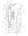
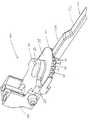
様々な実施形態では、本発明による外科用器具は、外科用器具の細長いシャフト組立体に対してエンドエフェクタを動かすか、または関節運動させるためのシステムを含むことができる。少なくとも1つの実施形態では、図3〜図7を参照すると、外科用器具100は、エンドエフェクタ106および細長いシャフト組立体104を可動に接続することができる関節運動継手114を含むことができる。様々な実施形態では、関節運動継手114は、エンドエフェクタ106が単一の平面内で、もしくはその代わりに複数の平面内で、シャフト組立体104に対して動かされることを可能にすることができる。いずれの場合も、関節運動継手114は、1つ以上の旋回軸116(図5)を含むことができ、この旋回軸116の周りでエンドエフェクタ106は関節運動されうる。様々な実施形態では、図5および図6を参照すると、外科用器具100は、ロック機構118をさらに含むことができ、このロック機構118は、エンドエフェクタ106と細長いシャフト組立体104との間の相対関係を固着するか、またはロックすることができる。少なくとも1つの実施形態では、ロック機構118は、ロック部材120を含むことができ、このロック部材120は、エンドエフェクタ106とシャフト組立体104との間の相対運動を防ぐか、または少なくとも部分的に抑制するために、エンドエフェクタ106に対してスライドされ、かつエンドエフェクタ106に係合することができる。少なくとも1つの実施形態では、ロック部材120は、エンドエフェクタ106の歯312(図5および図6)のうち少なくとも1つに係合するように構成されていてよく、ロック部材120と歯312との間の相互作用は、以下により詳細に説明されるように、エンドエフェクタ106が軸116の周りを回転することを防ぐか、または少なくとも部分的に抑制することができるようになっている。 In various embodiments, a surgical instrument according to the present invention can include a system for moving or articulating the end effector relative to the elongated shaft assembly of the surgical instrument. In at least one embodiment, referring to FIGS. 3-7,
様々な実施形態では、図7〜図9を参照すると、ロック機構118は、ロック部材120に動作可能に接続されうるアクチュエータ122をさらに含むことができる。少なくとも1つの実施形態では、アクチュエータ122は、ピン124を含むことができ、このピン124は、ロック部材120のスロット121内に受容されてよく、このため、アクチュエータ122がハンドル部分102に対してスライドされると、ピン124は、スロット121の側壁に接触し、かつ、エンドエフェクタ106に対してロック部材120を動かす(motivate)ことができる。少なくとも1つの実施形態では、アクチュエータ122は、エンドエフェクタ106から引き離されて、すなわち近位に引っ張られて、ロック部材120をエンドエフェクタ106から外すことができる。図示されてはいないが、ロック部材120をエンドエフェクタ106から外すために、アクチュエータ122が遠位に動かされるか、または回転さえさせられることができる、他の実施形態が構想される。いずれの場合も、ロック機構118は、戻しバネ126(図6)をさらに含むことができ、この戻しバネ126は、アクチュエータ122が解放された後で、ロック部材120をエンドエフェクタ106と係合させるように、ロック部材120をエンドエフェクタ106に向かって、すなわち遠位に動かすように構成されることができる。他のロック機構は、2005年4月7日に出願された、名称を「SURGICAL INSTRUMENT WITH ARTICULATING SHAFT WITH SINGLE PIVOT CLOSURE AND DOUBLE PIVOT FRAME GROUND」とする、米国特許出願第11/100,772号、2005年9月29日に出願された、名称を「SURGICAL INSTRUMENT WITH ARTICULATING SHAFT WITH RIGID FIRING BAR SUPPORTS」とする、米国特許出願第11/238,358号、および2006年7月24日に出願された、名称を「SURGICAL STAPLING AND CUTTING DEVICE AND METHOD FOR USING THE DEVICE」とする、米国特許出願第11/491,626号に開示されており、これら米国特許出願の開示内容全体が、参照により本明細書に組み込まれる。 In various embodiments, referring to FIGS. 7-9, the
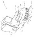
様々な実施形態では、図1および図2を参照すると、アクチュエータ122は、外科医がアクチュエータ122の外面をつかみ、前述のようにアクチュエータ122を近位に引っ張ることができるように輪郭を付けられていてよい。アクチュエータ122を動かすために、少なくとも1つの実施形態では、外科医がハンドルグリップ127に対してアクチュエータ122を動かすことができるように、外科医は、例えば片手をハンドルグリップ127上に置き、もう一方の手をアクチュエータ122の上に置くことができる。他の様々な実施形態では、図10〜図13を参照すると、アクチュエータ122’は、外科医が、外科用器具を操作するのに片手だけを必要とすることができるように構成されうる。より詳細には、少なくとも1つの実施形態では、アクチュエータ122’は、アクチュエータ122’から延びるフック、すなわち突起部115を含むことができ、この突起部115は、外科医が片手でハンドルグリップ127を保持し、その手の少なくとも1本の指を遠位に延ばして少なくとも1つの突起部115をつかみ、前述のようにアクチュエータ122’を近位に引っ張ることを可能にすることができる。アクチュエータ122’は、突起部115を有するものとして本明細書に記載されているが、アクチュエータ122、または任意の他の適切なアクチュエータは、突起部115、および/もしくは、外科医が片手で外科用器具100を操作するのを助けることができる任意の他の適切な特徴部を含んでもよい。少なくとも1つの実施形態では、突起部115は、突起部115に対する外科医の握りを改善することができ、かつ外科医に他の人間工学的利点を与えることができる弾性材料もしくは「手触りが柔らかな(soft-touch)」材料で、少なくとも部分的に構成され、かつ/またはそれらの材料でコーティングされてよい。様々な実施形態では、例えば、アクチュエータ122’は、シャフト組立体104と動作可能に係合されることができ、これにより、エンドエフェクタ106およびシャフト組立体104は、アクチュエータ122’により長さ方向軸の周りを回転させられることができる。このような実施形態では、外科医は、前述のようにエンドエフェクタ106を関節運動させること、および/または、エンドエフェクタ106を所定の位置に回転させることによって、手術部位においてエンドエフェクタ106を方向付けることができる。少なくとも1つの実施形態では、外科医は、突起部115のうち1つに対して指を置くこと、およびその突起部に対して力を加えることにより、アクチュエータ122’を回転させることができる。様々な実施形態では、外科医は、突起部115に対して指を置くこと、および、アクチュエータ122’のあらゆる望ましくない運動、それに対応してエンドエフェクタ106のあらゆる望ましくない運動に抵抗することによって、アクチュエータ122’を所定の位置に保持することができる。 In various embodiments, referring to FIGS. 1 and 2, the
様々な実施形態では、本発明による外科用器具は、例えば、エンドエフェクタを軟組織の上に閉じるか、またはクランプするためのシステムを含むことができる。少なくとも1つの実施形態では、図2、図5、図8、および図9を参照すると、外科用器具100は、閉鎖トリガー128、駆動リンク130、駆動体132、および閉鎖管134を含むことができる。様々な実施形態では、閉鎖トリガー128の作動時に、閉鎖トリガー128は、駆動リンク130、駆動体132、および閉鎖管134を遠位に転置するように構成されうる。さらに詳細には、少なくとも1つの実施形態では、駆動リンク130は、トリガー128に旋回可能に接続された第1の端部と、駆動体132に旋回可能に接続された第2の端部と、を含むことができ、トリガー128がハンドルグリップ127に向かって回転することによって、リンク130を前方に駆動し、駆動体ガイド136(図8)により定められた軸に沿って駆動体132をスライドさせることができるようになっている。様々な実施形態では、駆動体132は、この駆動体132から延びる突起部133を含むことができ、この突起部133は、駆動体ガイド136のスロット135内にスライド可能に受容されることができ、スロット135は、駆動体132が動かされるときの駆動体132の通路(path)を定めることができる。様々な実施形態では、閉鎖管134は、駆動体132と動作可能に係合されてよく、前述のように駆動体132が遠位に動かされると、閉鎖管134はアンビル112に係合し、アンビル112を下方に旋回させることができるようになっている。主に図5を参照すると、閉鎖管134は、関節運動継手114の上をスライドし、ステープルカートリッジ110に対してアンビル112を旋回させるように構成されうる。少なくとも1つの実施形態では、図9に示されるように、閉鎖管134は、この閉鎖管134から延びる突起部135を有する近位端部を含むことができ、この突起部135は、駆動体132の転置が閉鎖管134に伝達されるように、駆動体132のスロット131に受容されることができる。 In various embodiments, a surgical instrument according to the present invention can include, for example, a system for closing or clamping an end effector over soft tissue. In at least one embodiment, referring to FIGS. 2, 5, 8, and 9, the
様々な実施形態では、前述のように、ロック機構118は、エンドエフェクタ106とシャフト組立体104との間の相対運動を防ぐか、または少なくとも部分的に抑制することができる。例えば、軟組織がアンビル112とステープルカートリッジ110との間にクランプされる状況では、エンドエフェクタ106とシャフト組立体104との間の相対運動が、アンビル112とステープルカートリッジ110との間にクランプされた軟組織に対して剪断力を加えることがあり、この剪断力は、その軟組織に損傷を与える場合がある。様々な実施形態では、図10〜図13を参照すると、エンドエフェクタ106が閉じられたときにエンドエフェクタ106とシャフト組立体104との間の相対運動を防ぐか、または少なくとも軽減するために、エンドエフェクタ閉鎖システムは、アクチュエータ122’がそのロックされていない位置に動かされることを防ぐようロック機構118に係合するように構成されうる。事実上、少なくとも1つの実施形態では、閉鎖トリガー128の作動は、エンドエフェクタ106を閉じることができるだけでなく、ロック機構118がロックを外されることを防ぐこともできる。様々な実施形態では、図10〜図13を参照すると、外科用器具100’は、駆動体132を含むことができ、この駆動体132は、駆動体132がトリガー128によって遠位に動かされるとアクチュエータ122’に接触するか、もしくはぴったりと隣接して位置付けられるように構成されてよく、これにより、アクチュエータ122に関して前述したようにアクチュエータ122’が近位に動かされることを防ぐことができる。より詳細には、ロック部材120をエンドエフェクタ106に対してスライドさせ、関節運動継手114のロックを外すために、図10および図11に示されるように、トリガー132が作動される前に、アクチュエータ122’は近位にスライドされてよい。しかしながら、図13を参照すると、トリガー132の作動時に、駆動体132は、アクチュエータ122’に接触するか、または隣接して位置付けられるように構成されてよく、アクチュエータ122’は、エンドエフェクタ106からロック部材120を外すように近位に動かされることができないようになっている。その結果、エンドエフェクタ閉鎖システムは、エンドエフェクタ106が閉じた後でこのエンドエフェクタ106が関節運動することを防ぐことができ、これにより、エンドエフェクタ内にクランプされた軟組織に剪断力が伝えられる可能性を低減する。 In various embodiments, as described above, the
前述したことに加えて、エンドエフェクタ閉鎖システムは、エンドエフェクタが閉じられたというフィードバックを外科医に与えることができ、外科医がエンドエフェクタのロックを外し、エンドエフェクタを関節運動させるためには、外科医は、エンドエフェクタが関節運動させられうる前に、まずエンドエフェクタを少なくとも部分的に再び開けなければならない。より詳細には、エンドエフェクタ106が閉じられたときの駆動体132とアクチュエータ122’との間の相互作用のために、外科医が関節運動継手114のロックを外すためにアクチュエータ122’を近位に引っ張ろうとすると、駆動体132は、アクチュエータ122’が動くことを実質的に防ぐことができ、それにより、エンドエフェクタ106が閉じられたことと、アクチュエータ122’が動かされることができ、かつ関節運動継手のロックが外されることができる前にエンドエフェクタ106が最初に開かれなければならないことと、を外科医に知らせる。様々な実施形態では、このようなエンドエフェクタ閉鎖システムは、外科医が、外科用器具、および/またはエンドエフェクタの中に捕捉された組織もしくはエンドエフェクタの周りの組織を損傷することを防ぐことができる。より詳細には、少なくとも1つの実施形態では、前述のように閉鎖管134がアンビル112を閉じるために前進させられると、閉鎖管134は、アンビル112に力を加えてアンビル112を閉位置に保持することができる。様々な状況において、この力は、関節運動継手114の中で摩擦力を生じることができ、この摩擦力は、エンドエフェクタ106が関節運動継手114の周りを回転することを、妨げるとまではいかなくても抑制することができる。前述したエンドエフェクタ閉鎖システムがない実施形態では、外科医が最初にエンドエフェクタを少なくとも部分的に開けずにこれらの摩擦力に打ち勝とうとする場合、外科医は、例えば外科用器具の1つ以上の構成要素を曲げるか、または壊すことがある。しかしながら、本発明の様々な実施形態では、例えば、駆動体132は、前述のように外科医が関節運動ロック120を解放することを防ぐことができ、その結果、外科医は、関節運動継手114のロックを外す機会を与えられることができず、ましてエンドエフェクタ106を関節運動させる機会を与えられることはできない。 In addition to the foregoing, the end effector closure system can provide feedback to the surgeon that the end effector has been closed so that the surgeon can unlock the end effector and articulate the end effector. Before the end effector can be articulated, it must first be at least partially reopened. More specifically, due to the interaction between the
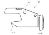
様々な実施形態では、本発明による外科用器具は、例えばアンビル112を開位置、閉位置、および部分的に閉じた位置に位置付けることができる、エンドエフェクタ閉鎖システムを含むことができる。少なくとも1つの実施形態では、外科医は、アンビル112がその閉位置に動かされる前に、アンビル112を部分的に閉じた位置に動かし、エンドエフェクタが再び位置付けられるか、もしくは関節運動させられるべきであるかどうかを評価することができる。このような実施形態では、アンビル112は、アンビル112が完全に閉じられる前に、剪断力、もしくは少なくとも実質的な剪断力を軟組織に加えることなく、アンビル112とステープルカートリッジ110との中間に位置付けられた軟組織に対して動かされうる。少なくとも1つの実施形態では、アンビル112は、アンビル112がその部分的に閉じた位置にある場合に、アンビル112とステープルカートリッジ110との間に位置付けられた軟組織をこのアンビル112がクランプしないように構成されうる。その代わりに、アンビル112は、このアンビル112がその閉位置に動かされるときにより大きなクランプ力を加える前に、アンビル112がその部分的に閉じた位置にあるときに軟組織に軽いクランプ力を加えるように構成されてもよい。少なくとも1つのこのような実施形態では、外科用器具は、トリガーを含むことができ、このトリガーは、アンビル112の開位置に対応する第1の位置(図11)と、アンビル112の部分的に閉じた位置に対応する第2の位置(図12)と、アンビル112の閉位置に対応する第3の位置(図13)との間で動かされることができる。様々な実施形態では、図8および図9を参照すると、トリガー128は、ハンドル部分102のハウジング103に旋回可能に取り付けられてよく、トリガー128は、その第1の位置と、第2の位置と、第3の位置との間でピン129の周りを回転させられうるようになっている。様々な実施形態では、図8、図9、図17、および図18を参照すると、外科用器具100は、トリガーロック148をさらに含むことができ、このトリガーロック148は、トリガー128に係合し、前述した、トリガー128の第1の位置、第2の位置、および第3の位置のうち少なくとも1つの位置でトリガー128を選択的にロックするように構成されうる。少なくとも1つの実施形態では、トリガー128は、カム面140、第1のノッチ142、および第2のノッチ144を含むピボット端部138を含むことができ、トリガーロック148は、第1のノッチ142および第2のノッチ144に係合するように構成されうる。より詳細には、図8および図9を参照すると、外科用器具100は、トリガーロックバネ150をさらに含むことができ、このトリガーロックバネ150は、トリガーロック148の従動部分149をカム面140に対して付勢するように構成されてよく、第1のノッチ142または第2のノッチ144のいずれかが従動部分149と整列された場合に、トリガーロックバネ150が第1のノッチ142または第2のノッチ144それぞれの中に従動部分149を押し込むことができるようになっている。少なくとも1つの実施形態では、主に図8および図9を参照すると、トリガーロック148は、ピン151によりハンドル部分102のハウジング103に旋回可能に取り付けられていてよい。様々な実施形態では、トリガーロックバネ150は、トリガーロック148のボタン部分152とハウジング103との中間で圧縮されることができ、トリガーロックバネ150は、ピン151の周りでトリガーロック148を回転させ、かつトリガー128のカム面140に対してトリガーロック148を下方に付勢することができるようになっている。 In various embodiments, a surgical instrument according to the present invention can include an end effector closure system that can position the
前述したことに加えて、少なくとも1つの実施形態では、第1のノッチ142は、トリガー132がその第2の位置に動かされてアンビル112がその部分的に閉じた位置に動かされると、従動部分149と整列させられうる。様々な実施形態では、従動部分149は、第1のノッチ142の中にしっかりと保持されてよく、このため、トリガーロック148は、トリガー132がその第3の位置に動かされ、かつ/またはその第1の位置に戻されることができる前に、トリガー132から手動で外されることを必要とするかもしれない。少なくとも1つの実施形態では、図8および図9を参照すると、外科医は、ロック部材148のボタン部分152を押し下げることができ、これにより、ロック部材148がピン151の周りを回転させられ、従動部分149が上方に引き上げられトリガー128との係合から外れる。他の様々な実施形態では、第1のノッチ142は、トリガー132に力が加えられると従動部分149がスライドして第1のノッチ142から出るように構成されてもよい。いずれの場合も、従動部分149が第1のノッチ142から外された後、外科医は、トリガー132をその第3の位置に選択的に動かすか、またはトリガー132を解放し、例えばトリガーバネがトリガー132をその第1の位置に戻すことを可能にすることができる。少なくとも1つの代替的実施形態では、第1のノッチ142および従動部分149は、トリガー132がその第2の位置に動かされた後、トリガー132がその第1の位置に戻されうる前にその第3の位置に動かされなければならないように、構成されうる。いずれの場合も、少なくとも1つの実施形態では、トリガー132の第2のノッチ144は、トリガー132がその第3の位置に動かされ、かつアンビル112がその閉位置に動かされると、従動部分149と整列することができる。第1のノッチ142と同様に、第2のノッチ144は、ロック部材148がトリガー132から外され、かつ/または第2のノッチ144から従動部分149を除去するようにトリガー132に十分な力が加えられるまで、内部に従動部分149を保持するように構成されてよい。様々な実施形態では、その後、トリガーバネは、トリガー132をその第3の位置から第2の位置に動かすことができ、この際、外科医は、前述したことと同様に第1のノッチ142から従動部分149を外すことを必要とされうる。少なくとも1つの代替的実施形態では、第1のノッチ142は、従動部分149が、第1のノッチ142を通り過ぎてスライドし、外科医が第1のノッチ142から従動部分149を除去することを必要とせずにトリガー132をその第3の位置から第1の位置へ動かすことを可能にすることができるように、構成されてよい。 In addition to the foregoing, in at least one embodiment, the
前述したことに加え、図示されてはいないが、ロック部材148のボタン部分152は、閉鎖トリガー128がその第1の位置にある場合に、例えば外科用器具のハウジング103の中に引っ込んで(recessed)いてもよい。代替的実施形態では、ボタン部分152は、ハウジング103と水平に(flushly)位置付けられてもよいし、あるいは、ボタン部分152は、ハウジング103からわずかに延出していてもよい。いずれの場合も、少なくとも1つの実施形態では、ボタン部分152は、閉鎖トリガー128がその第2の位置に動かされると、ハウジング103に対して外側に動くことができる。このような動きは、外科用器具のアンビルがその部分的に閉じた位置にあるという視覚的フィードバックを外科医に与えることができる。加えて、ボタン部分152の動きは、音声フィードバックおよび/または触覚フィードバックも伴ってよい。いずれの場合も、外科医は、ボタン部分152が外側に動かされた後でボタン部分152にアクセスすることができ、これにより、前述のようにロック部材148がトリガー128から外されうる。様々な実施形態では、ボタン部分152は、トリガー128がその第2の位置から第3の位置に動かされると、さらに外側に動くことができる。前述したことと同様に、このような動きは、アンビルがいまやその閉位置にあるという視覚的合図を外科医に与えることができ、かつ、このような動きは、前述のように音声フィードバックおよび/または触覚フィードバックも伴ってよい。ボタン152は、トリガー128がその第1の位置と第3の位置との間を進むと外側に動くものとして前述されているが、本発明はそのように限定されるものではない。それどころか、ボタン152、もしくは任意の他の適切な表示器が、任意の適切な方法で外科医にフィードバックを与えてもよい。 In addition to the foregoing, although not shown, the
代替的実施形態では、図示されてはいないが、アンビル112は、前述した3つの位置、すなわち開位置、閉位置、および部分的に閉じた位置よりも多くの位置で保たれるか、または保持されてもよい。少なくとも1つの実施形態では、アンビル112は、開位置、閉位置、および2つ以上の中間位置で保持されることができる。そのような実施形態では、アンビル112は、アンビル112がその閉位置に向かって動かされるときに、これらの中間位置を通過して進み、エンドエフェクタ106の中に捕捉された軟組織にますます大きな力を加えることができる。少なくとも1つの実施形態では、前述したことと同様に、トリガー132は、アンビル112の様々な中間位置に対応することができる複数のノッチを含むことができる。様々な代替的実施形態では、図示されていないが、エンドエフェクタ閉鎖システムは、トリガー132、およびそれに対応してアンビル112が複数の位置で保持されることを可能にしうる、ラチェット組立体を含むことができる。このような実施形態では、アンビル112およびトリガー132は、トリガー132と動作可能に係合されるつめ車(ratchet wheel)と旋回可能に係合される歯止め(pawl)により、適所に保持されうる。 In an alternative embodiment, although not shown, the
様々な実施形態では、図10〜図13を参照すると、前述のように、アクチュエータ122’とハンドル部分102’との間の相対運動は、ロック部材120が転置されうる範囲を制御するために、制限されてよい。より詳細には、図10および図11を参照すると、アクチュエータ122’の遠位部分は、その遠位部分から延びる突起部123を含むことができ、この突起部123は、キャビティ125に受容されることができ、アクチュエータ122’の転置は、キャビティ125の近位壁117および遠位壁119により制限されうる。少なくとも1つの実施形態では、図10および図11に示されるように、トリガー128がその第1の位置にある場合、アクチュエータ122は、図10に示されるように突起部123が遠位壁119に接触することができる遠位位置から、図11に示されるように突起部123が遠位壁119に接触しない、より近位の位置まで動かされることができる。この、より遠位の位置では、前述のように、ロック部材120は、エンドエフェクタ106から外されることができ、エンドエフェクタ106は、シャフト組立体104に対して回転されうる。トリガー128がその第2の位置にある場合、図12を参照すると、駆動体132は、突起部123が近位壁117に接して位置付けられることができないように、アクチュエータ122’の運動範囲を制限することができる。しかしながら、少なくとも1つの実施形態では、アクチュエータ122’は、エンドエフェクタ106からロック部材120を外すために十分な距離だけ近位に動かされてよい。このような状況では、例えばアンビル112は軟組織の上に部分的に閉じられてよいが、外科医はエンドエフェクタ106を再び位置付けることができる。図13に示されるように、トリガー128がその第3の位置にある場合、駆動体132は、アクチュエータ122’を遠位に押しやることができ、突起部132が遠位壁119に接触するか、または遠位壁119に隣接して位置付けられ、かつ、アクチュエータ122’が関節運動継手114のロックを外すように十分に動かされることができないようになっている。 In various embodiments, referring to FIGS. 10-13, as described above, the relative movement between the actuator 122 ′ and the
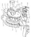
様々な実施形態では、本発明による外科用器具は、前述のようにエンドエフェクタ内で切断部材および/またはステープル駆動体を前進させるように構成された発射駆動装置を含むことができる。少なくとも1つの実施形態では、図8、図9、および図19〜図25を参照すると、外科用器具100の発射駆動装置は、発射トリガー160、第1の発射リンク162、第2の発射リンク164、および発射部材166を含むことができる。様々な実施形態では、発射トリガー160は、細長いシャフト組立体104の中でナイフバー168を前進させるために、発射部材166ならびに発射リンク162および164のうち少なくとも1つと動作可能に係合されてよい。少なくとも1つの実施形態では、ナイフバー168は、エンドエフェクタ106の(不図示の)切断部材、および(不図示の)ステープル駆動体と動作可能に係合されてよく、切断部材は、例えば、組織を切開するように構成されてよく、ステープル駆動体は、ステープルカートリッジ110からステープルを配備するように構成されてよい。切断部材およびステープル駆動体は、参照により本明細書中に先に組み込まれている米国特許第6,905,057号および同第7,044,352号に十分に開示されているので、これらの装置は、本明細書においてさらに詳細には説明しない。他の切断部材およびステープル駆動体は、2006年9月29日に出願された、名称を「SURGICAL STAPLES HAVING COMPRESSIBLE OR CRUSHABLE MEMBERS FOR SECURING TISSUE THEREIN AND STAPLING INSTRUMENTS FOR DEPLOYING THE SAME」とする米国特許出願第11/541,123号、および2007年1月11日に出願された、名称を「SURGICAL STAPLING DEVICE WITH A CURVED CUTTING MEMBER」とする米国特許出願第11/652,169号に開示されており、これら米国特許出願の全開示内容が参照により本明細書に組み込まれる。 In various embodiments, a surgical instrument according to the present invention can include a firing drive configured to advance a cutting member and / or staple driver within an end effector as described above. In at least one embodiment, referring to FIGS. 8, 9, and 19-25, the firing drive of
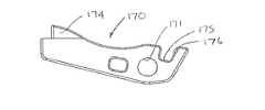
様々な実施形態では、主に図19および図20を参照すると、発射トリガー160は、ピン161により外科用器具のハウジング103(図8および図9)に旋回可能に接続されていてよい。使用時には、少なくとも1つの実施形態では、発射トリガー160は、発射部材166ならびに発射リンク162および164を遠位に前進させるために、ピン161の周りで旋回させられうる。様々な実施形態では、発射トリガー160は、スロット159を含むことができ、このスロット159は、発射ピン172を受容するように構成されてよい。様々な実施形態では、発射トリガー160が図2に示された位置からハンドルグリップ127に隣接した位置まで作動されるか、または回転されると、スロット159の側壁は、発射ピン172に係合し、発射ピン172を遠位に前進させるように構成されていてよい。少なくとも1つの実施形態では、図23を参照すると、発射駆動装置は、歯止め170をさらに含むことができ、この歯止め170は、孔171を含むことができる。様々な実施形態では、孔171は、発射ピン172がトリガー160によって遠位に前進させられたときに発射ピン172が歯止め170を同様に遠位に前進させることができるように、発射ピン172の少なくとも一部を受容するように構成されてよい。様々な実施形態では、図24を参照すると、歯止め170は歯174を含むことができ、発射部材166は凹部167を含むことができ、この凹部167は、歯174を受容するように構成されていてよい。使用時に、歯止め170が発射ピン172により遠位に前進させられ、かつ歯174が凹部167の側壁と係合されると、歯止め170は、同様に発射部材166を遠位に前進させることができる。様々な実施形態では、歯止め170は、ほぼ直線の通路に沿って発射ピン172により遠位に前進させられうる。そのような実施形態では、スロット159は、発射ピン172と協働して発射トリガー160の回転運動を歯止め170の並進運動に変えることができる、弓状の外形を含むことができる。少なくとも1つの実施形態では、歯止め170に加えられる力は、完全にではないにしても、大体は遠位方向に向けられてよい。その結果として、このような実施形態では、歯止め170がステープラフレーム184に結合されるか、または付着される可能性は、軽減されうる。 In various embodiments, referring primarily to FIGS. 19 and 20, the firing
様々な実施形態では、歯止め170は、歯止め170が発射部材166から動作可能に外される第1の位置と、図19および図20を参照して歯止め170が発射部材166と動作可能に係合される第2の位置との間で旋回されることができる。主に図21〜図25を参照すると、発射駆動装置は、歯止め170をその第1の位置と第2の位置との間で旋回させるように構成されうる、ティルター機構(tilter mechanism)178をさらに含むことができる。使用時に、発射トリガー160が作動されると、歯止め170は、少なくとも最初は、ティルター機構178に対して動くことができ、このため、歯止め170の少なくとも一部がティルター機構178に接触し、歯止め170を上方に旋回させて発射部材166と動作可能に係合させることができる。少なくとも1つの実施形態では、歯止め170は、主に図23を参照すると、ティルター機構178の中心部分から延びる突起部179(図25)を受容するように構成されてよい、溝175を含むことができる。少なくとも1つの実施形態では、歯止め170が遠位に前進させられると、溝175の近位壁176は、突起部179のカム面に接触することができ、ピボットピン172により歯止め170に加えられる力のために、歯止め170は、歯174が前述のように発射部材166の凹部167内に位置付けられうるように上方に旋回されるか、または回転されることができる。歯止め170が旋回された後、歯止め170は、歯止め170がエンドエフェクタ106に向かって前進させられると、ティルター機構178を遠位に引くことができる。さらに詳細には、少なくとも1つの実施形態では、ティルター機構178は、変形可能部材180を含むことができ、この変形可能部材180は、変形可能部材180とステープラフレーム184との間の相互作用により、ステープラフレーム184に対するティルター機構178の動きが少なくとも部分的に抑制されるように、ステープラフレーム184のスロット182内に受容されることができる。別の言い方をすれば、変形可能部材180とスロット182の側壁との間の静止摩擦力のため、ティルター機構178がステープラフレーム184に対して「引かれる」ことができる前に、これらの摩擦力に打ち勝つのに十分な力が、ティルター機構178に加えられなければならない。 In various embodiments, the
発射トリガー160が作動されて、発射部材166が前進させられた後、トリガー160は、解放され、図2に示されるその非作動位置まで戻ってよく、歯止め170は、発射部材166から外され、図19に示されるその最初の位置まで後退させられてよい。さらに詳細には、少なくとも1つの実施形態では、外科用器具100は、例えばトリガー160およびハウジング103と動作可能に係合された(不図示の)トリガーバネをさらに含むことができ、このトリガーバネは、歯止め170が発射部材166から外された後で、ピン161の周りでトリガー160を回転させ、発射ピン172を近位に駆動するように構成されていてよい。様々な実施形態では、歯止め170は、この歯止め170が、ティルター機構178によって、図24に示されるようなその第2の位置から、前述したようなその第1の位置まで旋回されると、発射部材166から外されることができる。そのような実施形態では、歯止め170は、少なくとも最初は、ティルター機構178に対して動かされることができ、このため、溝175の遠位壁177は、突起部179の第2のカム面に接触することができ、かつ、トリガー160もしくは戻しバネ(return spring)186により発射ピン172に加えられる力のために、歯止め170を下方に回転させることができ、歯止め170の歯174が発射部材166の凹部167から外されることができるようになっている。その後、トリガー160および/もしくは戻しバネ186は、発射部材166に対して歯止め170を引っ張るか、または後退させることができる。様々な実施形態では、前記と同様に、歯止め170は、スロット182内でティルター機構178を近位に引くように構成されてよい。前記の結果として、歯止め170は、その第1の位置または第2の位置に付勢される必要がない。様々な状況において、歯止め170は、付勢バネにより歯止め170に加えられる力に打ち勝つ必要なく、その第1の位置と第2の位置との間で自由に回転させられることができる。事実上、様々な実施形態では、歯止め170をその第1の位置と第2の位置との間で動かす力は、歯止め170の重力重量(gravitational weight)、および外科用器具の歯止め170と周囲の構成要素との間のあらゆる摩擦力に打ち勝てばよいだけである。 After firing
歯止め170がその元の位置にいったん戻されると、少なくとも1つの実施形態では、歯止め170の歯174は、もはや発射部材166の凹部167と整列されることはできない。一方、概して図19および図20を参照すると、歯止め170の歯174は、第1の発射リンク162の凹部163と整列されることができる。さらに詳細には、第1の発射リンク162は、発射部材166に旋回可能に接続されてよく、このため、前述のとおり、発射部材166が遠位に前進させられると、発射部材166は、発射部材166が以前に占めていた位置に第1の発射リンク162を引っ張ることができる。その結果、発射トリガー160が2回目に作動すると、歯止め170は、その第1の位置から第2の位置まで旋回されてよく、これにより、歯174は、凹部163と動作可能に係合され、歯止め170は、発射リンク162を遠位に前進させることができる。少なくとも1つの実施形態では、発射リンク162は、発射部材166およびナイフバー168を遠位に押し、これに対応して、エンドエフェクタ106内で切断部材およびステープル駆動体を遠位に前進させることができる。その後、歯止め170は、その第2の位置から第1の位置まで再び旋回されてよく、第1の発射リンク162に対して後退させられてよい。歯止め170が二度目にその元の位置に戻されると、歯止め170の歯174は、もはや第1の発射リンク162の凹部163と整列されることはできない。一方、前記と同様に、歯174は、第2の発射リンク164の凹部165と整列されてもよく、前述したプロセスが繰り返されうる。 Once
図示されてはいないが、本発明による外科用器具は、エンドエフェクタ106内で切断部材およびステープル駆動体をそれらの所望の位置まで前進させるために、2つより多いか、または少ない発射リンクを含むことができる。様々な実施形態では、図示されていないが、発射部材166は、2つ以上の凹部167を含むことができ、これにより歯止め170は、発射部材166をエンドエフェクタ106に向かって2回以上直接前進させることができる。少なくとも1つのそのような実施形態では、歯止め170は、前述のように、発射部材166を遠位に前進させた後、後退されてよく、このため、歯止め170が再び上方に傾斜されると、歯止め170は、発射部材166の別の凹部167に係合し、エンドエフェクタ106に向かって発射部材166を再び前進させることができる。その結果、少なくとも1つの実施形態では、発射リンク162および164は、必要とされなくてもよい。 Although not shown, the surgical instrument according to the present invention includes more or fewer firing links for advancing the cutting member and staple driver to their desired positions within the
様々な実施形態では、外科用器具は、歯止め170をその第1の位置および第2の位置のうち少なくとも一方の位置に動かすように構成された、1つ以上のバネ部材を含むことができる。少なくとも1つの実施形態では、図27および図28を参照すると、発射駆動装置は、歯止め170’、発射ピン172、およびティルター機構178’を含むことができ、前記と同様に、ティルター機構178’は、歯止め170’が遠位に前進させられると歯止め170’を上方に旋回させるように構成されていてよい。発射駆動装置は、ピボットバネ188をさらに含むことができ、このピボットバネ188は、歯止め170’に動作可能に接続されてよく、歯止め170’が図27に示されるようにその第2の位置まで上方に旋回されると、歯止め170’はピボットバネ188を屈曲させるか、または弾性的に曲げることができるようになっている。歯止め170’が前進させられた後、歯止め170’は、図28に示されるように、ピボットバネ188により第1の位置まで下方に旋回されうる。さらに詳細には、ピボットバネ188が屈曲されたときにそのピボットバネ188に蓄えられたポテンシャルエネルギーのため、バネ188は、歯止め170’がティルター機構178’および発射ピン172によりその第2の位置にもはや保持されなくなると、歯止め170’を下方に動かすことができる。その後、前述のとおり、歯止め170’は、発射部材166ならびに/または発射リンク162および164に対して後退させられてよい。様々な実施形態では、ティルター機構178’は、歯止め170をその第1の位置に旋回させるための第2のカム面を含まない場合もある。このような実施形態では、歯止め170’は、前述のように、発射ピン172に加えられる力により後退させられうる。様々な代替的実施形態では、図示されていないが、ティルター機構178’、および歯止め170’は、歯止め170’をその第1の位置まで下方に旋回させるための協働する特徴部も含むことができる。 In various embodiments, the surgical instrument can include one or more spring members configured to move the
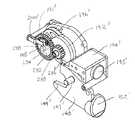
様々な実施形態では、図19および図20を参照すると、外科用器具100は、エンドエフェクタ106に対して発射部材166ならびに発射リンク162および164を動かすように構成されうる、バンド190をさらに含むことができる。少なくとも1つの実施形態では、バンド190の第1の端部は、例えば、発射部材166に接続されていてよく、発射部材166が遠位に前進させられると、バンド190も遠位に引っ張られることができるようになっている。様々な代替的実施形態では、バンド190は、第1の発射リンク162および/または第2の発射リンク164に接続されてもよい。少なくとも1つの実施形態では、バンド190は、リール、すなわちスプール192の少なくとも一部の周りに位置付けられてよく、バンド190が発射部材166により引っ張られると、バンド190は、リール192から配備されるか、またはほどかれることができるようになっている。少なくとも1つの実施形態では、バンド190の第2の端部は、外科用器具100の通常の操作条件下でバンド190がリール192から容易に外されることができないように、リール192に接続されてよい。いずれの場合も、バンド190が発射部材166により引っ張られると、リール192は、バンド190がリール192の周りに位置付けられる様式に応じて、時計回り方向または反時計回り方向のうちの一方に回転させられうる。発射部材166を後退させるためには、リール192は、反対方向に回転させられて、発射部材166ならびに発射リンク162および164を近位に動かし、かつリール192にバンド190を巻き付けることができる。 In various embodiments, referring to FIGS. 19 and 20,
様々な実施形態では、バンド190は、このバンド190がリール192のほぼ円柱状の表面に巻き付けられるように、リール192の周りに巻き付けられることができる。少なくとも1つの実施形態では、リール192の回転軸と円柱状の表面との間の距離は、リール192の周辺部(perimeter)の周りでほぼ等距離であってよい。これらの実施形態では、リール192の機械的拡大率は、バンド190が前述のように近位に引っ張られるときに、ほぼ一定のままであってよく、リール192がバンド190に引張力(pulling force)を加える能力は、ほぼ同じままであってよい。しかしながら、代替的実施形態では、リール192は、可変性の機械的拡大率をもたらすように構成されていてもよい。少なくとも1つの実施形態では、リール192は、非円柱状の表面を含むことができ、この非円柱状の表面上で、バンド190は、リール192の回転軸と非円柱状の表面との間の距離がリール192の周辺部の周りで等距離にならないように、巻かれることができる。その結果、これらの実施形態では、リール192がバンド190に引張力を加える能力は、バンド190がリール192に巻き付けられるにつれて、変化しうる。少なくとも1つの実施形態では、リール192は、カムとして作用することができ、リール192は、バンド190が最初に後退させられるとき、すなわち、例えば切断部材を後退させる力が最も大きくなりうるときに、バンド190に更なる力を与えるように最適化されうる形状を含むことができる。 In various embodiments, the
様々な実施形態では、図29〜図42を参照すると、発射トリガー160は、外科用器具100の戻し機構と選択的に係合されてよい。少なくとも1つの実施形態では、前述のように発射トリガー160が歯止め170により発射部材166と動作可能に係合されると、発射トリガー160の作動により、発射部材166を遠位に前進させることができ、発射トリガー160がバンド190により発射部材166と動作可能に係合されると、発射トリガー160の作動により、発射部材166を近位に後退させることができる。様々な実施形態では、戻し機構は、手で作動されて、発射部材166から発射トリガー160を外し、かつ発射トリガー160をリール192と動作可能に係合させることができる。少なくとも1つの実施形態では、戻し機構は、戻し輸送部(return carriage)194を含むことができ、この戻し輸送部194は、外科用器具のハウジング103に旋回可能に取り付けられてよく、戻し輸送部194が、図29に示されるような第1の位置、すなわち非作動位置と、図32に示されるような第2の位置、すなわち作動位置との間で旋回されることができるようになっている。少なくとも1つのこのような実施形態では、戻し輸送部194は、押しボタン部分195を含むことができ、押しボタン部分195は、この押しボタン部分195に力が加えられると、戻し輸送部194をその非作動位置から作動位置まで動かすように構成されてよい。 In various embodiments, referring to FIGS. 29-42, firing
戻し輸送部194が図29〜図31に示される非作動位置に位置付けられると、発射トリガー160は、前述のように発射部材166を前進させるように構成されていてよく、かつトリガー160のギア部分158は、トリガーギア196と動作可能に係合されてよい。様々な実施形態では、ギア部分158およびトリガーギア196は、ピン161の周りでのトリガー160の回転によって、戻しピン198により定められた軸の周りでトリガーギア196が駆動されうるように、動作可能に係合されてよい。少なくとも1つの実施形態では、戻し輸送部194がその非作動位置にある場合に、トリガーギア196は、トリガーギア196の回転が戻しピン198に伝えられないか、または少なくとも実質的に伝えられないように、戻しピン198の周りで自由に回転するように構成されてよい。より詳細には、図30を参照すると、戻しピン198のキー199が付勢されてトリガーギア196との係合から外れてよく、トリガーギア196の回転がキーギア(key gear)206およびリール192に伝えられないようになっている。その結果、戻し輸送部194がその非作動位置にある場合、トリガーギア160の作動により、リールは回転させられないか、または少なくとも実質的に回転させられない。 When the
切断部材およびステープル駆動体がエンドエフェクタ106の中で前進させられた後、戻し輸送部194は、その作動位置へ動かされてよい。様々な実施形態では、図30を参照すると、リール192は、そのリール192から延びるカム部材202を含むことができ、このカム部材202は、戻し輸送部194に接触し、かつ戻し輸送部194を下方に回転させることができる。少なくとも1つの実施形態では、カム部材202は、エンドエフェクタ106内で切断部材およびステープル駆動体を前進させるトリガー160の最終の作動の間、戻し輸送部194に接触することができる。少なくとも1つのこのような実施形態では、カム部材202は、発射トリガー160が3回目に作動した後で、戻し輸送部194に接触することができる。様々な実施形態では、図32〜図35を参照すると、ギア輸送部194がその作動位置に動かされると、戻し輸送部194は、トリガーギア196をリール192と動作可能に係合させるように構成されてよい。少なくとも1つの実施形態では、図33および図35を参照すると、戻し輸送部194は、付勢バネ200を含むことができ、戻し輸送部194がその非作動位置にある場合、バネ200は、図33に示される位置に配されてよく、戻し輸送部194が図35に示されるその作動位置に動かされると、バネ200は、戻しピン198に接触し、トリガーギア196に向かって戻しピン198を付勢することができる。少なくとも1つの実施形態では、図31を参照すると、トリガーギア196は、内部にD字型キャビティ197を含むことができ、このキャビティ197は、以下に説明される特定の状況下では、戻しピン198から延びるキー199を受容し、トリガーギア196をキーギア206およびリール192と動作可能に係合させることができる。様々な実施形態では、戻し輸送部194のその作動位置への移動は、外科用器具の戻し機構がトリガー160と係合されたことを外科医に知らせるために音声フィードバックおよび/または触覚フィードバックを伴ってもよい。 After the cutting member and staple driver have been advanced within the
前述したことに加えて、戻しピン198がトリガーギア196に向かってスライドされるときに、D字型キャビティ197は、キー199がキャビティ197にすぐに入らないように位置付けられてよい。これとは反対に、図31を参照すると、バネ200は、キー199がトリガーギア196の面204に最初に接するように戻しピン198を付勢することができる。しかしながら、トリガー160が解放され、その非作動位置まで戻された後、D字型キャビティ197は、バネ200が図36に示されるようにキャビティ197内にキー199を付勢することができるように、回転させられ、キー199と整列させられてよい。少なくとも1つの実施形態では、図31を参照すると、戻しピン198がトリガーギア196に向かってスライドされると、戻しピン198の端部は、図32に示されるように戻し輸送部194のスロット193の中に受容されることができる。キー199がキャビティ197内に挿入された後、トリガー160の次の作動により、D字型キャビティ197の駆動表面210は、キー199に接し、戻しピン198を図37および図38に示される位置まで回転させることができる。事実上、少なくとも1つの実施形態では、トリガー160の作動により、約半回転だけキー199を回転させることができ、最初はほぼ下方に延びている(図36)キー199は、キー199がほぼ上方に延びる(図37)ように回転させられうる。その後、トリガー160は解放されてよく、トリガーギア194は、キー199に対して回転させられてよく、キー199は、図39〜図41に示されるようにほぼ上方の方向に向けられたままであってよい。 In addition to the foregoing, the D-shaped
様々な実施形態では、主に図38を参照すると、キーギア206は、戻しピン198の回転がキーギア206に伝えられうるように、戻しピン198と動作可能に係合されてよい。少なくとも1つの実施形態では、キーギア206は、戻しピン198のキー199をスライド可能に受容するように構成されうる、鍵型の孔212を含むことができる。少なくとも1つのこのような実施形態では、キー199は、戻しピン198がトリガーギア196と係合された場合、トリガーギア196の凹部197およびキーギア206の孔212の双方と動作可能に係合されてよい。様々な代替的実施形態では、キーギア206は、戻しピン198に固定して取り付けられてよい。このような実施形態では、戻しピン198がトリガーギア196に対してスライドされると、キーギア206もトリガーギア196に対してスライドされることができる。様々な実施形態では、概して図38を参照すると、リール192は、このリール192に取り付けられた平歯車216を含むことができ、この平歯車216は、キーギア206の回転がリール192に伝えられうるように、キーギア206と動作可能に係合されることができる。少なくとも1つの実施形態では、前述のようにキーギア206がトリガーギア196に向かってスライドされると、このキーギア206はスライドされてリール192と動作可能に係合することができる。代替的実施形態では、平歯車216は、キーギア206がトリガーギア196に向かって付勢されているかどうかに関係なく、キーギア206が平歯車216と動作可能に係合するように構成されうる。 In various embodiments, primarily referring to FIG. 38, the
前記の結果として、戻し輸送部194が、図32に示されるその作動位置に位置付けられると、トリガー160の作動により、リール192を回転させ、バンド190をリール192の少なくとも一部に巻き付けることができる。戻し輸送部194が作動したときにキー199がトリガーギア196と動作可能に係合されることができない場合は、リール192は、手で回転されてバンド190を後退させることができる。少なくとも1つのそのような実施形態では、図33および図37を参照すると、ボルト、すなわち締め具218がリール192と動作可能に係合されてよく、ボルト218の回転が、リール192の回転をもたらすことができるようになっている。様々な実施形態では、外科医は、外科用器具のハウジング103の開口部を通してボルト218を挿入し、ボルト218をリール192と係合させることができる。少なくとも1つの実施形態では、外科用器具100は、トリガー160の作動を数えることができる、(不図示の)計数機構をさらに含むことができ、少なくとも1つのそのような実施形態では、例えばボルト218は、リール192を回転させるために計数機構と動作可能に係合されることができる。その結果、様々な実施形態では、外科用器具は、リール192を巻き上げるための第1の、すなわち主たるアクチュエータ、および、第1のアクチュエータの代わりにリール192を巻き上げるように構成されうる第2のアクチュエータを含むことができる。 As a result of the foregoing, when the
様々な実施形態では、前述のように、リール192は、バンド190を引っ張り、発射部材166ならびに発射リンク162および164を近位に後退させるように構成されていてよい。さらに詳細には、前述のように、発射部材166ならびに発射リンク162および164は、発射部材166ならびに発射リンク162および164をそれらの最初の位置に再び位置付けるために、歯止め170に対して後退させられうる。そのような実施形態において、前述のように歯止め170が旋回可能である実施形態では特に、外科用器具100の戻し機構は、発射部材166ならびに発射リンク162および164が歯止め170に対して動いている間に、これら発射部材166ならびに発射リンク162および164との動作可能な係合(operative engagement)から外れた歯止め170を保持するようにさらに構成されていてもよい。さらに詳細には、戻し輸送部194が図35に示されるその作動位置まで動かされると、戻し輸送部194は、発射ピン172の端部に接触し、歯止め170に向かって発射ピン172をスライドさせるように構成されていてよく、これにより、発射ピン172は、歯止め170に係合して、歯止め170が上方に旋回するのを防ぐ。より詳細には、図34を参照すると、発射ピン172は、例えば、斜めの、かつ/または丸みのある表面を含みうる第1の端部220を含むことができ、戻し輸送部194が第1の端部220に接触すると、戻し輸送部194は歯止め170に向かって発射ピン172を押すことができるようになっている。少なくとも1つの実施形態では、歯止め170は、発射ピン172が歯止め170に向かって動かされると、発射ピン172から延びるキー222を受容するように構成されうる、凹部173を含むことができる。キー222および凹部173が動作可能に係合されると、発射ピン172は、歯止め170が上方に旋回して発射部材166ならびに発射リンク162および164と係合するのを防ぐことができる。 In various embodiments, as described above, the
発射部材166ならびに発射リンク162および164が後退させられた後、新しいステープルカートリッジ110がエンドエフェクタ106に固定されてよく、また、外科用器具100は、軟組織を再び切開し、かつステープル留めするのに外科用器具が使用されうるように、リセットされてよい。様々な実施形態では、図39〜図42を参照すると、戻し輸送部194は、図32に示されるその作動位置から、図40に示される非作動位置まで動かされうる。少なくとも1つの実施形態では、戻し輸送部194は、ボタン部分195に力が加えられると、上方に回転されるか、または旋回させられることができる。その代わりに、戻し輸送部194は、前述のようにエンドエフェクタ106を再び開けるために、図29を参照して、トリガーロック148が上方に回転されて閉鎖トリガー128から従動部分149を外すと、上方に動かされてもよい。より詳細には、トリガーロック148のボタン部分152に力が加えられると、トリガーロック148は上方に回転させられてよく、これにより、トリガーロック148から延びる突起部147が戻し輸送部194に接触し、戻し輸送部194を同様に上方に動かすことができる。いずれの場合も、図42を参照すると、戻し輸送部194がその非作動位置まで上方に動かされると、戻し輸送部194は、歯止め170から発射ピン172を外すことができ、さらに、トリガーギア196から戻しピン198を外すことができる。より詳細には、戻し輸送部194は、発射ピン172の斜めの、または丸みのある端部221に接するように構成されてもよく、このため、戻し輸送部194が上方に回転されると、戻し輸送部194は、歯止め170から離れるように戻しピン172をスライドさせ、かつキー222を凹部173から外すことができる。同様に、戻し輸送部194が上方へ動かされると、スロット193の側壁は、D字型凹部197からキー199を外すために、戻しピン198の端部に接触し、トリガーギア196から離れるように戻しピン198をスライドさせるように構成されることができる。手短に言えば、少なくとも例示された実施形態では、ロック部材148のボタン部分152が押し下げられ、戻し輸送部194が上方へ動かされると、外科用器具はリセットされることができ、もう一度再利用されることができる。 After the firing
前述の外科用器具は、切断部材およびステープル駆動体がエンドエフェクタ106内で完全に前進させられた後でリセットされうるが、例えば戻し輸送部194のボタン部分195は、切断部材およびステープル駆動体がエンドエフェクタ106内で部分的にのみ前進させられた後で押し下げられてもよい。様々な実施形態では、戻し輸送部194は、戻し輸送部194の向かい合う側面の間に延在するガイドピン191をさらに含むことができる。少なくとも1つのそのような実施形態では、ガイドピン191は、フレーム184のガイドスロット185(図31)の中にスライド可能に受容されることができ、このため、スロット185およびピン191は、戻し輸送部194のための通路を定めることができる。様々な実施形態では、ガイドピン191およびガイドスロット185は、戻し輸送部194が発射ピン172および戻しピン198に係合すること、および戻し輸送部194が前述のようにその作動位置から非作動位置まで動かされたときに戻し輸送部194が外科用器具をリセットすること、を確実にするように構成されることができる。 The aforementioned surgical instrument can be reset after the cutting member and staple driver have been fully advanced within the
様々な実施形態では、外科用器具100は、発射駆動装置が例えばエンドエフェクタ106の中で切断部材およびステープル駆動体を前進させ、かつ/もしくは後退させることを防ぐか、または少なくとも部分的に抑制するための、制動装置をさらに含むことができる。少なくとも1つの実施形態では、図43を参照すると、フレーム184は、制動面187を含むことができ、この制動面187は、バンド190に制動力(braking force)を加えるように構成されてよい。より詳細には、バンド190が前述のように近位に、かつ/または遠位に引っ張られると、フレーム184は、バンド190が制動面187の上をスライドし、かつ摩擦力がバンド190と制動面187との間に生じるように構成されることができる。様々な実施形態では、図44を参照すると、制動面187'は、発射部材166とリール192との間のバンド190の通路が制動面187'により妨害され、かつ著しい垂直力がバンド190に加えられうるように、構成されてよい。 In various embodiments, the
少なくとも1つの実施形態では、バンド190は、バンド190が静止している場合に制動面187'と係合されてよく、このため、バンド190と制動面187'との間の静止摩擦力は、バンド190に引張力が加えられたときに、バンド190が制動面187'に対して動くことを少なくとも最初は防ぐことができる。バンド190に加えられる引張力が静止摩擦力を上回ると、バンド190は、制動面187'に対して動かされることができる。そのような実施形態は、エンドエフェクタ106内で切断部材および/またはステープル駆動体を前進させるためにトリガー160が2回以上作動される場合に、特に有用でありうる。より詳細には、トリガー160の作動後、歯止め170は、前述のように発射部材166に対して後退させられてよく、様々な実施形態では、バンド190と制動面187'との間の摩擦力は、歯止め170が後退させられたときに発射部材166ならびに/または発射リンク162および164が近位に、かつ/もしくは遠位に動くことを防ぐか、あるいは少なくとも部分的に抑制することができる。前記の結果として、歯止め170が発射部材166ならびに発射リンク162および164の凹部に対して動かされると、歯止め170の歯174と発射部材166ならびに発射リンク162および164の凹部との間の整列が維持されうる。 In at least one embodiment, the
同様に、少なくとも1つの実施形態では、バンド190の剛性は、発射部材166ならびに発射リンク162および164を所定の位置に保持することを支援することもできる。より詳細には、発射部材166が「後退する」か、または近位に動くためには、発射部材166は、バンド190を近位に押さなければならず、事実上、リール192にバンド190を巻き付けなければならない。様々な実施形態では、バンド190の剛性は、リール192にバンド190を巻き付けるかなりの力が必要とされ、その結果、発射部材166が適所に保持されうるようなものでありうる。リール192にバンド190を巻き付けるのに必要な力をさらに増大させるために、図44を参照すると、バンド190の通路は、バンド190がリール192に接線方向で巻き付けられないように制御されうる。より詳細には、バンド190の通路が、リール192にバンド190が非接線方向で巻き付けられるようなものであれば、バンド190を通して伝えられる力の一部は失われ、その結果、巻き上げるリール192の機械的拡大率は不十分となる。 Similarly, in at least one embodiment, the rigidity of the
様々な実施形態では、外科用器具100は、制動装置を含むことができ、この制動装置は、リール192または発射駆動装置の任意の他の適切な構成要素と係合されて、例えば、発射部材166ならびに/または発射リンク162および164が非意図的に後退させられるのを防ぐことができる。少なくとも1つの実施形態では、図示されてはいないが、制動装置は、第1の位置と第2の位置との間を動かされてよく、制動装置が第1の位置にあるときは、この制動装置は、例えば第1の制動力をバンド190に加えることができる。少なくとも1つのこのような実施形態では、例えば、制動装置は、第2の位置にあるときに、バンド190に第2の制動力を加えることができ、この第2の制動力は、第1の制動力より大きいか、または小さくてよい。様々な代替的実施形態では、制動装置は、この制動装置が第2の位置にある場合、バンド190または発射駆動装置の任意の他の部分と係合されていなくてもよい。様々な実施形態では、図示されていないが、外科用器具100は、リール192および/またはバンド190に制動力を加えることができる、戻り止め機構を含むことができる。少なくとも1つのそのような実施形態では、戻り止め機構は、球状の戻り止め、ならびに、リール192および/またはバンド190に対して球状の戻り止めを付勢して係合させるためのバネ部材を含むことができる。 In various embodiments, the
様々な実施形態では、外科用器具100は、ラチェットを含むことができ、このラチェットは、リール192が第1の方向に回ることを可能にするが、様々な状況では、リール192が第1の方向と反対の方向に回るのを防ぐことができる。少なくとも1つの実施形態では、図45〜図49を参照すると、外科用器具100は、ラチェット組立体230を含むことができ、このラチェット組立体230は、つめ車(ratchet wheel)232、およびラチェット歯止め(ratchet pawl)234を含むことができる。様々な実施形態では、つめ車232は、主に図47および図48を参照するとつめ車232がラチェット歯236を含むことができる点を除いて、前述したキーギア206とほぼ同じように働くことができる。ラチェット歯236は、ラチェット歯止め234とのラチェット係合(ratchet engagement)に起因して、戻し輸送部194’がその非作動位置にある場合(図47)につめ車232が例えば時計回り方向に回されるのを防ぐことができる。より詳細には、各ラチェット歯236は、平面240を含むことができ、図48を参照すると、平面240のうち少なくとも1つが歯止め234のエッジ235に接することができ、これにより、つめ車232が時計回り方向に回転させられるのを防ぐことができる。 In various embodiments, the
各ラチェット歯236は、傾斜面238をさらに含むことができ、傾斜面238は、つめ車232が反時計回り方向に回されたときに、歯止め234の下でスライドするように構成されていてよい。前記の結果として、ラチェット組立体230は、例えばバンド190が発射部材166により遠位に引っ張られることを可能にするが、少なくとも戻し輸送部194がその非作動位置にある場合に、バンド190が近位に動かされることを防ぐか、または少なくとも実質的に抑制することができる。戻し輸送部194について前述したように、戻し輸送部194’がその作動位置まで下方に旋回されると、つめ車232は、トリガーギア196’に向かってスライドされて、ラチェット歯止め234との動作可能な係合から外れることができる。結果として、その後、つめ車232は、ラチェット歯止め234からの干渉なしで、もしくは少なくとも実質的な干渉なしで、時計回り方向または反時計回り方向のどちらにでも回転されることができる。つめ車232がトリガーギア196’に向かってスライドされない様々な代替的実施形態では、ラチェット歯止め234は、戻し輸送部194'がその作動位置まで動かされると、下方に動かされ、ラチェット歯236との動作可能な係合から外れることができる。いずれの場合も、戻し輸送部194’がその作動位置にある場合、トリガーギア196’および戻しピン198’は、つめ車232およびカム192’を回転させてバンド190および発射部材166を後退させることができる。 Each ratchet tooth 236 can further include an
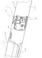
様々な実施形態では、図50を参照すると、外科用器具100は、エンドエフェクタ106、および細長いシャフト組立体104を含むことができ、エンドエフェクタ106およびシャフト組立体104は、関節運動継手114により旋回可能に接続されていてよい。前記に概説したように、関節運動継手114は、エンドエフェクタ106が軸116の周りでシャフト組立体104に対して動かされるか、または関節運動されることを可能にすることができる。様々な状況において、外科医は、エンドエフェクタ106を関節運動させて患者の体内の手術部位に、より容易にアクセスすることができる。より詳細には、外科医は、患者の体内に少なくとも部分的に挿入されたカニューレを通じて、エンドエフェクタ106およびシャフト組立体104を挿入することができ、いったんエンドエフェクタ106がカニューレを通過すると、ステープル留めされるべき、かつ/もしくは切開されるべき手術部位の、例えば軟組織に対してエンドエフェクタ106を位置付けるために、エンドエフェクタ106は旋回されるか、または関節運動されうる。いったんエンドエフェクタ106が位置付けられると、エンドエフェクタ106とシャフト組立体104との間の相対関係は、さらに以下でより詳細に説明されるように、ロック機構により固着されるか、またはロックされることができる。 In various embodiments, referring to FIG. 50, the
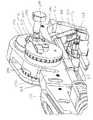
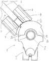
少なくとも1つの実施形態では、図51および図52を参照すると、関節運動継手114は、エンドエフェクタロック部材300、およびピボット302を含むことができる。様々な実施形態では、図53〜図56を参照すると、エンドエフェクタロック部材300は、ロック部材300をエンドエフェクタ106に固定することができるコネクタ部分320を含むことができ、図52を参照すると、シャフト組立体104は、ピボットコネクタ342を含むことができ、ピボットコネクタ342は、このピボットコネクタ342から延びるピボット302を含むことができる。様々な実施形態では、ロック部材300は、ピボット302の少なくとも一部を内部に受容するようにサイズ決めされ、かつ構成されうる、孔301を含むことができる。少なくとも1つの実施形態では、ピボット302および孔301は、エンドエフェクタ106が軸116の周りで自由に回転することができるように構成されていてよい。他の様々な実施形態では、ピボット302および孔301は、ピボット302と孔301との間の摩擦がエンドエフェクタ106とシャフト組立体104との間の相対運動を可能にすることができるが、その相対運動に抵抗することができるように、構成されていてよい。図示されていないが、関節運動継手114は、2つ以上の軸またはピボットを含むことができ、この周りでエンドエフェクタ106が回転されうる。 In at least one embodiment, referring to FIGS. 51 and 52, articulation joint 114 can include an end
様々な実施形態では、外科医は、エンドエフェクタ106が軸116の周りを旋回するように、例えば手術部位の周りの腔側壁に対してエンドエフェクタ106を押すこと、およびシャフト組立体104に力を加えることにより、シャフト組立体104に対してエンドエフェクタ106を関節運動させることができる。その後、外科医がエンドエフェクタ106を再び中心に置く(re-center)こと、すなわちエンドエフェクタ106およびシャフト組立体104をある線に沿って方向付けることを望む場合、外科医は、例えば、エンドエフェクタ106を再び腔側壁に置き、かつ、前述のようにシャフト組立体104に力を加えることができる。様々な実施形態では、図51および図52を参照すると、外科用器具100は、シャフト組立体104に対してエンドエフェクタ106を、自動的に再度中心に置くか、または少なくとも実質的に再度中心に置くことができる、再中心化機構(re-centering mechanism)を含むことができる。様々な実施形態では、エンドエフェクタロック部材300は、中心化表面(centering surface)316を含むことができ、細長いシャフト組立体104は、中心化シャフト328および付勢部材330を含むことができ、付勢部材330は、中心化シャフト328を中心化表面316に対して付勢するように構成されうる。少なくとも1つのそのような実施形態では、中心化表面316は、軸116のほぼ両側に配されていてよく、これにより、中心化シャフト328は、ほぼ均等なトルクもしくはモーメントをロック部材300に加えることができ、追加の原動力(motivating force)がない状態で、ほぼ中心の位置にエンドエフェクタ106を保持することができる。前述のように、エンドエフェクタ106がそのような原動力により関節運動されると、ロック部材300は、中心化シャフト328のうちの1つを近位に転置させ、かつ、その中心化シャフト328と動作可能に係合された付勢部材330を圧縮するように構成されうる。より詳細には、付勢部材330は、ガイド331と、中心化シャフト328から延びる少なくとも1つの突起部329との間に位置付けられてよく、このため、突起部329がシャフト328により近位に動かされると、付勢部材330はガイド331と突起部329との間で圧縮される。原動力が取り除かれた後、圧縮された付勢部材330は、拡張して、中心化シャフト328によりロック部材300の中心位置まで、または付勢部材330により加えられたトルクがほぼ釣り合う位置まで、ロック部材300を回転させることができる。付勢部材330は、コイルバネとして図示されているが、付勢部材330は、任意の適切な弾性部材を含むことができる。 In various embodiments, the surgeon presses the
様々な実施形態では、原動力が取り除かれた後でもエンドエフェクタ106をその関節運動された位置に保持するために、ロック機構が用いられてよい。少なくとも1つの実施形態では、図53〜図56を参照すると、エンドエフェクタロック部材300は、第1の表面308を有する第1の部分、第2の表面304を有する第2の部分、歯312、および歯312の間に定められた凹部314を含むことができ、さらに以下により詳細に説明するように、歯312および凹部314は、エンドエフェクタ106とシャフト組立体104との間の相対関係を固着するか、またはロックするために、シャフト組立体ロック部材と動作可能に係合されるように構成されうる。様々な実施形態では、歯312および凹部314は、第1の表面308と第2の表面304との中間に位置付けられうる。少なくとも1つの実施形態では、第1の表面308は、孔301から第1の周辺部310まで延びることができ、第2の表面304は、孔301から第2の周辺部306まで延びることができる。様々な実施形態では、第1の周辺部310は、第1の平面を定めることができ、第2の周辺部306は、第2の平面を定めることができ、歯312および凹部314は、第1の平面と第2の平面との中間に位置付けられうる。第1の周辺部310が第2の周辺部306とは異なる実施形態では、歯312は、第1の周辺部310と第2の周辺部306との間で、ある角度で延びるか、または傾斜していてよい。様々な実施形態では、歯312は、歯312が第2の周辺部306に交わる点よりも、軸116からさらに離れた点で、第1の周辺部310に交わることができる。少なくとも1つの実施形態では、歯312のうち少なくとも1つが、第1の軸313を定めることができ、この第1の軸313は、第1の表面308と第2の表面304との間で、第1の表面308および/または回転軸116に対して垂直ではない方向に延びることができる。そのような実施形態では、歯312は、例えば関節運動継手114に隣接して位置する軟組織の上をスライドすることができる。別の言い方をすれば、歯312の角度を付けた表面もしくは傾斜した表面のために、エンドエフェクタ106が関節運動されたときに歯312が関節運動継手114の周りの軟組織を捕捉するか、または軟組織に当たる可能性が減少されうる。少なくとも1つの実施形態では、歯312は、第1の周辺部310を超えて延びていなくてよく、このため、例えば、第1の周辺部310の少なくとも一部が軟組織と接触している場合、第1の周辺部310および歯312は、前述のように、軟組織に対して容易にスライドすることができる。 In various embodiments, a locking mechanism may be used to hold the
前述したことに加え、本発明の実施形態は、以前の外科用器具よりもかなりの利点を提供することができる。より詳細には、図57を参照すると、以前のエンドエフェクタの関節運動継手は、例えば、ロック部材299などのロック部材を含んでおり、このロック部材は、ロック部材の周辺部から外側に延びる歯298を含む。その結果、エンドエフェクタが外科用器具のシャフト組立体に対して関節運動されると、歯298は、周囲の軟組織を捕捉するか、もしくは軟組織に当たる場合があり、その軟組織に外傷を生じる可能性がありうる。様々な状況において、組織は、隣接する歯298の間に捕捉される場合があり、これにより、エンドエフェクタが関節運動されると、軟組織は、関節運動継手の中に引っ張られることがあるか、また、継手の、相対的に動く構成要素により挟まれることがある。前記に概説し、図58に示されるように、ロック部材の歯が角度を付けられているか、もしくは傾斜している本発明の実施形態では、軟組織は、歯の上をより容易に素通りし、軟組織が関節運動継手の中に引っ張られうる可能性を軽減することができる。 In addition to the foregoing, embodiments of the present invention can provide significant advantages over previous surgical instruments. More particularly, referring to FIG. 57, a prior art end effector articulation joint includes a locking member, such as, for example, a locking
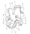
前記に概説したように、図59〜図62を参照すると、外科用器具100は、ロック部材120をさらに含むことができ、このロック部材120は、エンドエフェクタ106に対してスライドされてよく、シャフト組立体104とエンドエフェクタ106との間の相対運動を防ぐか、または少なくとも制限するように、エンドエフェクタ106と動作可能に係合されてよい。少なくとも1つの実施形態では、ロック部材120は、エンドエフェクタ106がロック部材120に対して動くことを防ぐように、歯312のうち少なくとも1つに係合するように構成されてよい。より詳細には、ロック部材120は、端部分338およびシャフト部分340を含むことができ、端部分338は、凹部336を含むことができ、この凹部336は、ロック部材300の歯312を、ぴったり適合した関係で、または締まりばめの関係であっても、受容するように構成されることができる。様々な代替的実施形態では、ロック部分338は、前記と同様のぴったり適合した関係、または締まりばめの関係で、凹部314のうち少なくとも1つの中に受容されうる。いずれの場合も、外科用器具100は、ロック部材120を付勢してエンドエフェクタロック部材300と係合させるように構成されてよいバネ126をさらに含むことができる。凹部336が歯312と整列されていない場合、少なくとも1つの実施形態では、バネ126によりロック部材120に加えられる付勢力は、歯312のうち1つが凹部336と整列されるまで、ロック部材120がエンドエフェクタロック部材300と接触し、かつ軸116の周りでエンドエフェクタロック部材300を回転させるようにしうる。様々な実施形態では、バネ126は、螺旋バネ、板バネ、または他の付勢材料を含む、任意の適切な付勢部材を含むことができる。 As outlined above, with reference to FIGS. 59-62, the
様々な代替的実施形態では、図63〜図67を参照すると、外科用器具は、孔301、第1の表面358を含む第1の部分、第2の表面354(図67)を含む第2の部分、およびコネクタ部分320を含むエンドエフェクタロック部材350を含むことができる。エンドエフェクタロック部材350は、歯362、および、歯362の間に定められた凹部364も含むことができ、少なくとも1つの実施形態では、歯362および凹部364は、第1の表面358と第2の表面354との中間に位置付けられうる。様々な実施形態では、図65〜図67を参照すると、歯362は、第1の表面358の第1の周辺部357および/または第2の表面354の第2の周辺部353を超えて延びていなくてよい。少なくとも1つのそのような実施形態では、歯362は、第1の表面358と第2の表面354との間に完全に位置付けられるか、または収容されていてよい。少なくとも1つの代替的実施形態では、歯362は、第1の周辺部357および/または第2の周辺部353から部分的に延びていてもよい。様々な実施形態では、第1の周辺部357および第2の周辺部353は、それらの間に外面を定めることができ、その外面において、凹部364が定められうる。前述した特徴の結果として、エンドエフェクタロック部材350は、関節運動継手に隣接して位置する軟組織に当たることなく、その軟組織に対してスライドすることができる。様々な実施形態では、歯362は、前述した相対的なスライドをさらに容易にするために、尖っていない(blunted)か、または丸くなっていてよい。少なくとも1つの実施形態では、図63〜図65を参照すると、ロック機構は、歯362および凹部364のうち少なくとも1つに係合するように構成されていてよく、かつ、端部分388およびシャフト部分390を含むロック部材382を含むことができる。少なくとも1つの実施形態では、前記と同様、端部分388は、例えば歯362のうち少なくとも1つに係合するように構成されうる、凹部394を含むことができる。 In various alternative embodiments, referring to FIGS. 63-67, the surgical instrument includes a
本明細書に開示された装置は、1回使用した後に処分されるように設計されてもよく、あるいは、複数回使用されるように設計されてもよい。しかしながら、いずれの場合も、この装置は、少なくとも1回使用した後で、再利用のために再調整されうる。再調整は、装置の分解ステップ、それに続く特定の部品の洗浄もしくは交換ステップ、および、その後の再組立ステップのうち任意の組み合わせを含むことができる。具体的には、装置は分解されてよく、装置の任意の数の特定の部品もしくは部分が、任意の組み合わせで選択的に交換されるか、または除去されてよい。特定の部分を洗浄および/もしくは交換すると、装置は、再調整施設で、または外科手術の直前に外科チームによって、次の使用のために再組立されることができる。装置の再調整には、分解、洗浄/交換、および再組立のための様々な技術を利用することができることを、当業者は認識するであろう。そのような技術を使用すること、およびその結果得られる再調整された装置はすべて、本願の範囲内である。 The devices disclosed herein may be designed to be disposed of after a single use, or may be designed to be used multiple times. In either case, however, the device can be reconditioned for reuse after at least one use. Reconditioning can include any combination of equipment disassembly steps, followed by cleaning or replacement of specific parts, and subsequent reassembly steps. In particular, the device may be disassembled and any number of the particular parts or parts of the device may be selectively replaced or removed in any combination. Once a particular part has been cleaned and / or replaced, the device can be reassembled for subsequent use either at a reconditioning facility or by a surgical team immediately prior to surgery. Those skilled in the art will recognize that various techniques for disassembly, cleaning / replacement, and reassembly can be utilized to recondition the device. The use of such techniques and the resulting reconditioned device are all within the scope of this application.
好ましくは、本明細書に記載された発明は、手術の前に処理される。まず、新しい器具、または使用済みの器具が手に入れられ、必要であれば洗浄される。器具は、次に滅菌されうる。一滅菌技術では、器具は、プラスチックバッグまたはTYVEKバッグなど、閉じられ密閉された容器の中に置かれる。容器および器具は、次に、γ放射線、x線、または高エネルギー電子などの、容器を貫通することができる放射線の場に置かれる。放射線により、器具の表面、および容器の中の細菌が死滅する。滅菌された容器は、その後滅菌容器の中に保管されてよい。密閉された容器は、医療施設で開けられるまで器具を滅菌状態に保つ。 Preferably, the invention described herein is processed before surgery. First, a new or used instrument is obtained and cleaned if necessary. The instrument can then be sterilized. In one sterilization technique, the instrument is placed in a closed and sealed container, such as a plastic or TYVEK bag. The container and instrument are then placed in a field of radiation that can penetrate the container, such as gamma radiation, x-rays, or high energy electrons. Radiation kills the surface of the instrument and the bacteria in the container. The sterilized container may then be stored in the sterilized container. The sealed container keeps the instrument sterile until it is opened in the medical facility.
本発明は、例示的なデザインを有するものとして説明されたが、本発明は、開示内容の精神および範囲内で、さらに改変されてもよい。ゆえに、本願は、本発明の一般的原理を用いた、本発明のあらゆる変形体、使用、または改作物(adaptations)を含むことを意図している。さらに本願は、本発明が属する技術分野において既知となるか、または慣行となるような、本開示内容からの発展(departures)を含むことを意図している。 While this invention has been described as having an exemplary design, the present invention may be further modified within the spirit and scope of the disclosure. This application is therefore intended to cover any variations, uses, or adaptations of the invention using its general principles. Furthermore, this application is intended to cover developments from the present disclosure as known or practiced in the art to which this invention belongs.
〔実施の態様〕
(1) 外科用器具において、
シャフトと、
エンドエフェクタと、
前記シャフトおよび前記エンドエフェクタを接続する継手であって、前記エンドエフェクタは、前記継手の周りで前記シャフトに対して動くことができ、前記継手は、第1の継手部材、および第2の継手部材を含み、前記第1の継手部材および前記第2の継手部材のうち一方は、前記エンドエフェクタに取り付けられ、前記第1の継手部材および前記第2の継手部材のうちもう一方は、前記シャフトに取り付けられ、前記第1の継手部材は、回転軸の周りで前記第2の継手部材に対して動くことができ、前記第1の継手部材は、
第1の周辺部を備える第1の部分であって、前記第1の部分は、前記回転軸と前記第1の周辺部との間に延在する、第1の部分、
第2の周辺部を備える第2の部分であって、前記第2の部分は、前記回転軸と前記第2の周辺部との間に延在し、前記第2の周辺部は、前記第1の周辺部とは異なる、第2の部分、
第1の歯であって、前記第1の歯は、前記第1の部分と前記第2の部分との中間に位置付けられる、第1の歯、
第2の歯、ならびに、
前記第1の歯と前記第2の歯との間に定められた凹部であって、前記凹部は、前記第1の部分と前記第2の部分との中間に位置付けられる、凹部、
を含む、継手と、
を含む、外科用器具。
(2) 実施態様1に記載の外科用器具において、
前記第1の歯は、第1の軸を定め、
前記第1の軸は、前記第1の部分と前記第2の部分との間で、前記第1の周辺部により定められる平面に対して垂直ではない方向に延びる、外科用器具。
(3) 実施態様1に記載の外科用器具において、
前記第1の歯は、第1の軸を定め、
前記第1の軸は、前記第1の部分と前記第2の部分との間で、前記回転軸に対して平行ではない方向に延びる、外科用器具。
(4) 実施態様1に記載の外科用器具において、
前記第1の歯と前記第1の部分との間の第1の交点は、第1の点を定め、
前記第1の歯と前記第2の部分との間の第2の交点は、第2の点を定め、
前記第1の点は、前記第2の点よりも前記回転軸からさらに離れている、外科用器具。
(5) 実施態様4に記載の外科用器具において、
前記第1の歯は、前記第1の周辺部を越えて延びない、外科用器具。Embodiment
(1) In surgical instruments,
A shaft,
An end effector;
A joint connecting the shaft and the end effector, the end effector being movable relative to the shaft about the joint, the joint comprising a first joint member and a second joint member One of the first joint member and the second joint member is attached to the end effector, and the other of the first joint member and the second joint member is attached to the shaft. Attached, the first coupling member is movable relative to the second coupling member about a rotational axis, the first coupling member being
A first portion comprising a first peripheral portion, wherein the first portion extends between the rotating shaft and the first peripheral portion;
A second part having a second peripheral part, wherein the second part extends between the rotating shaft and the second peripheral part, and the second peripheral part is the second part A second part, different from the peripheral part of 1,
A first tooth, wherein the first tooth is positioned intermediate the first portion and the second portion;
A second tooth, and
A recess defined between the first tooth and the second tooth, wherein the recess is positioned midway between the first portion and the second portion;
Including fittings, and
Including surgical instruments.
(2) In the surgical instrument according to
The first tooth defines a first axis;
The surgical instrument, wherein the first axis extends between the first portion and the second portion in a direction that is not perpendicular to a plane defined by the first periphery.
(3) In the surgical instrument according to
The first tooth defines a first axis;
The surgical instrument, wherein the first axis extends between the first part and the second part in a direction that is not parallel to the axis of rotation.
(4) In the surgical instrument according to
A first intersection between the first tooth and the first portion defines a first point;
A second intersection between the first tooth and the second portion defines a second point;
The surgical instrument, wherein the first point is further away from the axis of rotation than the second point.
(5) In the surgical instrument according to
The surgical instrument, wherein the first tooth does not extend beyond the first periphery.
(6) 実施態様1に記載の外科用器具において、
ロック機構、
をさらに含み、
前記ロック機構は、前記エンドエフェクタと前記シャフトとの間の相対運動を制限するために前記第1の歯および前記第2の歯のうち少なくとも一方に係合するように構成されている、外科用器具。
(7) 実施態様1に記載の外科用器具において、
前記エンドエフェクタと前記シャフトとの間の相対運動を防ぐように前記第1の歯および前記第2の歯のうち少なくとも一方に選択的に係合するためのロック手段、
をさらに含む、外科用器具。
(8) 実施態様1に記載の外科用器具において、
ロック機構、
をさらに含み、
前記ロック機構は、前記エンドエフェクタと前記シャフトとの間の相対運動を制限するために前記凹部に係合するように構成されている、外科用器具。
(9) 実施態様1に記載の外科用器具において、
前記第1の周辺部は、第1の平面を定めることができ、
前記第2の周辺部は、第2の平面を定めることができ、
前記第1の歯および前記凹部は、前記第1の平面と前記第2の平面との中間に位置付けられることができる、外科用器具。
(10) 手術のために器具を処理する方法において、
実施態様1の外科用器具を手に入れることと、
前記外科用器具を滅菌することと、
滅菌容器内に前記外科用器具を保管することと、
を含む、方法。(6) In the surgical instrument according to
Locking mechanism,
Further including
The surgical mechanism is configured to engage at least one of the first tooth and the second tooth to limit relative movement between the end effector and the shaft. Instruments.
(7) The surgical instrument according to
Locking means for selectively engaging at least one of the first tooth and the second tooth to prevent relative movement between the end effector and the shaft;
A surgical instrument further comprising:
(8) In the surgical instrument according to
Locking mechanism,
Further including
The surgical instrument, wherein the locking mechanism is configured to engage the recess to limit relative movement between the end effector and the shaft.
(9) In the surgical instrument according to
The first peripheral portion may define a first plane;
The second peripheral portion may define a second plane;
The surgical instrument, wherein the first tooth and the recess can be positioned midway between the first plane and the second plane.
(10) In a method of processing an instrument for surgery,
Obtaining the surgical instrument of
Sterilizing the surgical instrument;
Storing the surgical instrument in a sterile container;
Including a method.
(11) 外科用器具において、
シャフトと、
エンドエフェクタと、
前記シャフトおよび前記エンドエフェクタを接続する継手であって、前記エンドエフェクタは、前記継手の周りで前記シャフトに対して動くことができ、前記継手は、第1の継手部材、および第2の継手部材を含み、前記第1の継手部材および前記第2の継手部材のうち一方は、前記エンドエフェクタに取り付けられ、前記第1の継手部材および前記第2の継手部材のうちもう一方は、前記シャフトに取り付けられ、前記第1の継手部材は、回転軸の周りで前記第2の継手部材に対して動くことができ、前記第1の継手部材は、
第1の表面、
第2の表面、
第1の歯、
第2の歯、および、
前記第1の歯と前記第2の歯との間に定められた凹部であって、前記凹部は、前記第1の表面と前記第2の表面との中間に位置付けられる、凹部、
を含む、継手と、
を含む、外科用器具。
(12) 実施態様11に記載の外科用器具において、
前記第1の表面は、第1の周辺部を含み、
前記第2の表面は、第2の周辺部を含み、
前記第1の歯は、前記第1の周辺部および前記第2の周辺部を越えて延びない、外科用器具。
(13) 実施態様12に記載の外科用器具において、
前記第2の歯は、前記第1の周辺部および前記第2の周辺部を越えて延びない、外科用器具。
(14) 実施態様11に記載の外科用器具において、
前記第1の表面は、第1の周辺部を含み、
前記第2の表面は、第2の周辺部を含み、
前記第1の周辺部および前記第2の周辺部は、それらの間に外面を定め、
前記凹部は、前記外面において定められる、外科用器具。
(15) 実施態様11に記載の外科用器具において、
ロック機構、
をさらに含み、
前記ロック機構は、前記エンドエフェクタと前記シャフトとの間の相対運動を制限するために前記第1の歯および前記第2の歯のうち少なくとも一方に係合するように構成されている、外科用器具。(11) In surgical instruments,
A shaft,
An end effector;
A joint connecting the shaft and the end effector, the end effector being movable relative to the shaft about the joint, the joint comprising a first joint member and a second joint member One of the first joint member and the second joint member is attached to the end effector, and the other of the first joint member and the second joint member is attached to the shaft. Attached, the first coupling member is movable relative to the second coupling member about a rotational axis, the first coupling member being
A first surface;
A second surface,
The first tooth,
A second tooth, and
A recess defined between the first tooth and the second tooth, wherein the recess is positioned midway between the first surface and the second surface;
Including fittings, and
Including surgical instruments.
(12) The surgical instrument according to embodiment 11,
The first surface includes a first peripheral portion;
The second surface includes a second peripheral portion;
The surgical instrument, wherein the first tooth does not extend beyond the first periphery and the second periphery.
(13) The surgical instrument according to embodiment 12,
The surgical instrument, wherein the second tooth does not extend beyond the first periphery and the second periphery.
(14) The surgical instrument according to embodiment 11,
The first surface includes a first peripheral portion;
The second surface includes a second peripheral portion;
The first peripheral portion and the second peripheral portion define an outer surface therebetween;
The surgical instrument, wherein the recess is defined in the outer surface.
(15) The surgical instrument according to embodiment 11,
Locking mechanism,
Further including
The surgical mechanism is configured to engage at least one of the first tooth and the second tooth to limit relative movement between the end effector and the shaft. Instruments.
(16) 手術のために器具を処理する方法において、
実施態様11の外科用器具を手に入れることと、
前記外科用器具を滅菌することと、
滅菌容器内に前記外科用器具を保管することと、
を含む、方法。
(17) 外科用器具において、
シャフトと、
エンドエフェクタと、
前記シャフトおよび前記エンドエフェクタを接続する継手であって、前記エンドエフェクタは、前記継手の周りで前記シャフトに対して動くことができ、前記継手は、第1の継手部材、および第2の継手部材を含み、前記第1の継手部材および前記第2の継手部材のうち一方は、前記エンドエフェクタに取り付けられ、前記第1の継手部材および前記第2の継手部材のうちもう一方は、前記シャフトに取り付けられ、前記第1の継手部材は、回転軸の周りで前記第2の継手部材に対して動くことができ、前記第1の継手部材は、
第1の表面、
第2の表面、
第1の凹部、
第2の凹部、および、
前記第1の凹部と前記第2の凹部との間に定められた歯であって、前記歯は、前記第1の表面と前記第2の表面との中間に少なくとも部分的に位置付けられる、歯、
を含む、継手と、
を含む、外科用器具。
(18) 実施態様17に記載の外科用器具において、
前記第1の表面は、第1の周辺部を含み、
前記第2の表面は、第2の周辺部を含み、
前記歯は、前記第1の周辺部および前記第2の周辺部を越えて延びない、外科用器具。
(19) 実施態様17に記載の外科用器具において、
前記第1の表面は、第1の周辺部を含み、
前記第2の表面は、第2の周辺部を含み、
前記第1の周辺部および前記第2の周辺部は、それらの間に外面を定め、
前記第1の凹部および前記第2の凹部は、前記外面において定められる、外科用器具。
(20) 実施態様17に記載の外科用器具において、
ロック機構、
をさらに含み、
前記ロック機構は、前記エンドエフェクタと前記シャフトとの間の相対運動を制限するために前記歯に係合するように構成されている、外科用器具。(16) In a method of processing an instrument for surgery,
Obtaining the surgical instrument of embodiment 11;
Sterilizing the surgical instrument;
Storing the surgical instrument in a sterile container;
Including a method.
(17) In surgical instruments,
A shaft,
An end effector;
A joint connecting the shaft and the end effector, the end effector being movable relative to the shaft about the joint, the joint comprising a first joint member and a second joint member One of the first joint member and the second joint member is attached to the end effector, and the other of the first joint member and the second joint member is attached to the shaft. Attached, the first coupling member is movable relative to the second coupling member about a rotational axis, the first coupling member being
A first surface;
A second surface,
A first recess,
A second recess, and
A tooth defined between the first recess and the second recess, wherein the tooth is positioned at least partially between the first surface and the second surface. ,
Including fittings, and
Including surgical instruments.
(18) The surgical instrument according to
The first surface includes a first peripheral portion;
The second surface includes a second peripheral portion;
The surgical instrument, wherein the teeth do not extend beyond the first periphery and the second periphery.
(19) The surgical instrument according to
The first surface includes a first peripheral portion;
The second surface includes a second peripheral portion;
The first peripheral portion and the second peripheral portion define an outer surface therebetween;
The surgical instrument, wherein the first recess and the second recess are defined on the outer surface.
(20) The surgical instrument according to
Locking mechanism,
Further including
The surgical instrument, wherein the locking mechanism is configured to engage the teeth to limit relative movement between the end effector and the shaft.
(21) 手術のために器具を処理する方法において、
実施態様17の外科用器具を手に入れることと、
前記外科用器具を滅菌することと、
滅菌容器内に前記外科用器具を保管することと、
を含む、方法。(21) In a method of processing an instrument for surgery,
Obtaining the surgical instrument of
Sterilizing the surgical instrument;
Storing the surgical instrument in a sterile container;
Including a method.
Claims (10)
Translated fromJapaneseシャフトと、
エンドエフェクタと、
前記シャフトおよび前記エンドエフェクタを接続する継手であって、前記エンドエフェクタは、前記継手の周りで前記シャフトに対して動くことができ、前記継手は、第1の継手部材、および第2の継手部材を含み、前記第1の継手部材および前記第2の継手部材のうち一方は、前記エンドエフェクタに取り付けられ、前記第1の継手部材および前記第2の継手部材のうちもう一方は、前記シャフトに取り付けられ、前記第1の継手部材は、回転軸の周りで前記第2の継手部材に対して動くことができ、前記第1の継手部材は、
第1の周辺部を備える第1の部分であって、前記第1の部分は、前記回転軸と前記第1の周辺部との間に延在する、第1の部分、
第2の周辺部を備える第2の部分であって、前記第2の部分は、前記回転軸と前記第2の周辺部との間に延在し、前記第2の部分は、前記第1の部分から前記回転軸に沿った方向にずれており、前記第2の周辺部と前記回転軸との間の距離は、前記第1の周辺部と前記回転軸との間の距離よりも小さい、第2の部分、
第1の歯であって、前記第1の歯は、前記第1の部分と前記第2の部分との中間に位置付けられ、前記第1の周辺部から前記第2の周辺部へと延びる第1の軸を有するように延在する、第1の歯、
第2の歯、ならびに、
前記第1の歯と前記第2の歯との間に定められた凹部であって、前記凹部は、前記第1の部分と前記第2の部分との中間に位置付けられる、凹部、
を含む、継手と、
を含む、外科用器具。In surgical instruments,
A shaft,
An end effector;
A joint connecting the shaft and the end effector, the end effector being movable relative to the shaft about the joint, the joint comprising a first joint member and a second joint member One of the first joint member and the second joint member is attached to the end effector, and the other of the first joint member and the second joint member is attached to the shaft. Attached, the first coupling member is movable relative to the second coupling member about a rotational axis, the first coupling member being
A first portion comprising a first peripheral portion, wherein the first portion extends between the rotating shaft and the first peripheral portion;
A second portion having a second peripheral portion, wherein the second portion extends between the rotating shaft and the second peripheral portion, and the secondportion is the firstportionoffset from theportion in a direction along the rotation axis,the distance between the second peripheral portion and the rotation axis is smaller than the distance between the rotary shaft and the first peripheral portion , the second part,
A first tooth, wherein the first tooth is positioned between the first portion and the second portion and extends from the first peripheral portion to the second peripheral portion. A first tooth extending to have one axis;
A second tooth, and
A recess defined between the first tooth and the second tooth, wherein the recess is positioned midway between the first portion and the second portion;
Including fittings, and
Including surgical instruments.
前記第1の軸は、前記第1の部分と前記第2の部分との間で、前記第1の周辺部に沿って延びる平面に対して垂直ではない方向に延びる、外科用器具。The surgical instrument of claim 1, wherein
The surgical instrument wherein the first axis extends between the first portion and the second portion in a direction that is not perpendicular to a plane extending along the first periphery.
前記第1の軸は、前記第1の部分と前記第2の部分との間で、前記回転軸に対して平行ではない方向に延びる、外科用器具。The surgical instrument of claim 1, wherein
The surgical instrument, wherein the first axis extends between the first part and the second part in a direction that is not parallel to the axis of rotation.
前記第1の歯と前記第1の部分との間の第1の交点は、第1の点を定め、
前記第1の歯と前記第2の部分との間の第2の交点は、第2の点を定め、
前記第1の点は、前記第2の点よりも前記回転軸からさらに離れている、外科用器具。The surgical instrument of claim 1, wherein
A first intersection between the first tooth and the first portion defines a first point;
A second intersection between the first tooth and the second portion defines a second point;
The surgical instrument, wherein the first point is further away from the axis of rotation than the second point.
前記第1の歯は、前記第1の周辺部を越えて延びない、外科用器具。The surgical instrument according to claim 4, wherein
The surgical instrument, wherein the first tooth does not extend beyond the first periphery.
ロック機構、
をさらに含み、
前記ロック機構は、前記エンドエフェクタと前記シャフトとの間の相対運動を制限するために前記第1の歯および前記第2の歯のうち少なくとも一方に係合するように構成されている、外科用器具。The surgical instrument of claim 1, wherein
Locking mechanism,
Further including
The surgical mechanism is configured to engage at least one of the first tooth and the second tooth to limit relative movement between the end effector and the shaft. Instruments.
前記エンドエフェクタと前記シャフトとの間の相対運動を防ぐように前記第1の歯および前記第2の歯のうち少なくとも一方に選択的に係合するためのロック手段、
をさらに含む、外科用器具。The surgical instrument of claim 1, wherein
Locking means for selectively engaging at least one of the first tooth and the second tooth to prevent relative movement between the end effector and the shaft;
A surgical instrument further comprising:
ロック機構、
をさらに含み、
前記ロック機構は、前記エンドエフェクタと前記シャフトとの間の相対運動を制限するために前記凹部に係合するように構成されている、外科用器具。The surgical instrument of claim 1, wherein
Locking mechanism,
Further including
The surgical instrument, wherein the locking mechanism is configured to engage the recess to limit relative movement between the end effector and the shaft.
前記第1の周辺部は、前記第1の周辺部に沿って延びる第1の平面を定めることができ、
前記第2の周辺部は、前記第2の周辺部に沿って延びる第2の平面を定めることができ、
前記第1の歯および前記凹部は、前記第1の平面と前記第2の平面との中間に位置付けられることができる、外科用器具。The surgical instrument of claim 1, wherein
The first peripheral portion may define a first plane extending along the first peripheral portion;
The second peripheral portion may define a second plane extending along the second peripheral portion;
The surgical instrument, wherein the first tooth and the recess can be positioned midway between the first plane and the second plane.
請求項1の外科用器具を手に入れることと、
前記外科用器具を滅菌することと、
滅菌容器内に前記外科用器具を保管することと、
を含む、方法。In a method of processing an instrument for surgery,
Obtaining the surgical instrument of claim 1;
Sterilizing the surgical instrument;
Storing the surgical instrument in a sterile container;
Including a method.
Applications Claiming Priority (2)
| Application Number | Priority Date | Filing Date | Title |
|---|---|---|---|
| US11/821,455US7549564B2 (en) | 2007-06-22 | 2007-06-22 | Surgical stapling instrument with an articulating end effector |
| US11/821,455 | 2007-06-22 |
Publications (2)
| Publication Number | Publication Date |
|---|---|
| JP2009034492A JP2009034492A (en) | 2009-02-19 |
| JP5430883B2true JP5430883B2 (en) | 2014-03-05 |
Family
ID=39832587
Family Applications (1)
| Application Number | Title | Priority Date | Filing Date |
|---|---|---|---|
| JP2008161510AActiveJP5430883B2 (en) | 2007-06-22 | 2008-06-20 | Surgical stapling instrument with articulating end effector |
Country Status (4)
| Country | Link |
|---|---|
| US (1) | US7549564B2 (en) |
| EP (1) | EP2005902B1 (en) |
| JP (1) | JP5430883B2 (en) |
| CN (1) | CN101327141B (en) |
Families Citing this family (1008)
| Publication number | Priority date | Publication date | Assignee | Title |
|---|---|---|---|---|
| US11229472B2 (en) | 2001-06-12 | 2022-01-25 | Cilag Gmbh International | Modular battery powered handheld surgical instrument with multiple magnetic position sensors |
| US10285694B2 (en) | 2001-10-20 | 2019-05-14 | Covidien Lp | Surgical stapler with timer and feedback display |
| US20070084897A1 (en) | 2003-05-20 | 2007-04-19 | Shelton Frederick E Iv | Articulating surgical stapling instrument incorporating a two-piece e-beam firing mechanism |
| US9060770B2 (en) | 2003-05-20 | 2015-06-23 | Ethicon Endo-Surgery, Inc. | Robotically-driven surgical instrument with E-beam driver |
| US11311291B2 (en) | 2003-10-17 | 2022-04-26 | Covidien Lp | Surgical adapter assemblies for use between surgical handle assembly and surgical end effectors |
| US10022123B2 (en) | 2012-07-09 | 2018-07-17 | Covidien Lp | Surgical adapter assemblies for use between surgical handle assembly and surgical end effectors |
| US10041822B2 (en) | 2007-10-05 | 2018-08-07 | Covidien Lp | Methods to shorten calibration times for powered devices |
| US8182501B2 (en) | 2004-02-27 | 2012-05-22 | Ethicon Endo-Surgery, Inc. | Ultrasonic surgical shears and method for sealing a blood vessel using same |
| US8905977B2 (en) | 2004-07-28 | 2014-12-09 | Ethicon Endo-Surgery, Inc. | Surgical stapling instrument having an electroactive polymer actuated medical substance dispenser |
| US9072535B2 (en) | 2011-05-27 | 2015-07-07 | Ethicon Endo-Surgery, Inc. | Surgical stapling instruments with rotatable staple deployment arrangements |
| US11890012B2 (en) | 2004-07-28 | 2024-02-06 | Cilag Gmbh International | Staple cartridge comprising cartridge body and attached support |
| US11998198B2 (en) | 2004-07-28 | 2024-06-04 | Cilag Gmbh International | Surgical stapling instrument incorporating a two-piece E-beam firing mechanism |
| US8215531B2 (en) | 2004-07-28 | 2012-07-10 | Ethicon Endo-Surgery, Inc. | Surgical stapling instrument having a medical substance dispenser |
| US7947034B2 (en) | 2004-07-30 | 2011-05-24 | Tyco Healthcare Group Lp | Flexible shaft extender and method of using same |
| US20060079879A1 (en) | 2004-10-08 | 2006-04-13 | Faller Craig N | Actuation mechanism for use with an ultrasonic surgical instrument |
| US9339323B2 (en) | 2005-05-12 | 2016-05-17 | Aesculap Ag | Electrocautery method and apparatus |
| US8696662B2 (en) | 2005-05-12 | 2014-04-15 | Aesculap Ag | Electrocautery method and apparatus |
| US11291443B2 (en) | 2005-06-03 | 2022-04-05 | Covidien Lp | Surgical stapler with timer and feedback display |
| US11484312B2 (en) | 2005-08-31 | 2022-11-01 | Cilag Gmbh International | Staple cartridge comprising a staple driver arrangement |
| US8800838B2 (en) | 2005-08-31 | 2014-08-12 | Ethicon Endo-Surgery, Inc. | Robotically-controlled cable-based surgical end effectors |
| US7673781B2 (en) | 2005-08-31 | 2010-03-09 | Ethicon Endo-Surgery, Inc. | Surgical stapling device with staple driver that supports multiple wire diameter staples |
| US7934630B2 (en) | 2005-08-31 | 2011-05-03 | Ethicon Endo-Surgery, Inc. | Staple cartridges for forming staples having differing formed staple heights |
| US7669746B2 (en) | 2005-08-31 | 2010-03-02 | Ethicon Endo-Surgery, Inc. | Staple cartridges for forming staples having differing formed staple heights |
| US11246590B2 (en) | 2005-08-31 | 2022-02-15 | Cilag Gmbh International | Staple cartridge including staple drivers having different unfired heights |
| US10159482B2 (en) | 2005-08-31 | 2018-12-25 | Ethicon Llc | Fastener cartridge assembly comprising a fixed anvil and different staple heights |
| US9237891B2 (en) | 2005-08-31 | 2016-01-19 | Ethicon Endo-Surgery, Inc. | Robotically-controlled surgical stapling devices that produce formed staples having different lengths |
| US20070191713A1 (en) | 2005-10-14 | 2007-08-16 | Eichmann Stephen E | Ultrasonic device for cutting and coagulating |
| US7673783B2 (en) | 2005-11-04 | 2010-03-09 | Ethicon Endo-Surgery, Inc. | Surgical stapling instruments structured for delivery of medical agents |
| US7607557B2 (en) | 2005-11-04 | 2009-10-27 | Ethicon Endo-Surgery, Inc. | Surgical stapling instruments structured for pump-assisted delivery of medical agents |
| US7799039B2 (en) | 2005-11-09 | 2010-09-21 | Ethicon Endo-Surgery, Inc. | Surgical instrument having a hydraulically actuated end effector |
| US7673780B2 (en) | 2005-11-09 | 2010-03-09 | Ethicon Endo-Surgery, Inc. | Articulation joint with improved moment arm extension for articulating an end effector of a surgical instrument |
| US20070106317A1 (en) | 2005-11-09 | 2007-05-10 | Shelton Frederick E Iv | Hydraulically and electrically actuated articulation joints for surgical instruments |
| US7670334B2 (en) | 2006-01-10 | 2010-03-02 | Ethicon Endo-Surgery, Inc. | Surgical instrument having an articulating end effector |
| US7621930B2 (en) | 2006-01-20 | 2009-11-24 | Ethicon Endo-Surgery, Inc. | Ultrasound medical instrument having a medical ultrasonic blade |
| US11278279B2 (en) | 2006-01-31 | 2022-03-22 | Cilag Gmbh International | Surgical instrument assembly |
| US8708213B2 (en) | 2006-01-31 | 2014-04-29 | Ethicon Endo-Surgery, Inc. | Surgical instrument having a feedback system |
| US8161977B2 (en) | 2006-01-31 | 2012-04-24 | Ethicon Endo-Surgery, Inc. | Accessing data stored in a memory of a surgical instrument |
| US8820603B2 (en) | 2006-01-31 | 2014-09-02 | Ethicon Endo-Surgery, Inc. | Accessing data stored in a memory of a surgical instrument |
| US11224427B2 (en) | 2006-01-31 | 2022-01-18 | Cilag Gmbh International | Surgical stapling system including a console and retraction assembly |
| US7845537B2 (en) | 2006-01-31 | 2010-12-07 | Ethicon Endo-Surgery, Inc. | Surgical instrument having recording capabilities |
| US7644848B2 (en) | 2006-01-31 | 2010-01-12 | Ethicon Endo-Surgery, Inc. | Electronic lockouts and surgical instrument including same |
| US20110295295A1 (en) | 2006-01-31 | 2011-12-01 | Ethicon Endo-Surgery, Inc. | Robotically-controlled surgical instrument having recording capabilities |
| US7766210B2 (en) | 2006-01-31 | 2010-08-03 | Ethicon Endo-Surgery, Inc. | Motor-driven surgical cutting and fastening instrument with user feedback system |
| US7568603B2 (en) | 2006-01-31 | 2009-08-04 | Ethicon Endo-Surgery, Inc. | Motor-driven surgical cutting and fastening instrument with articulatable end effector |
| US9861359B2 (en) | 2006-01-31 | 2018-01-09 | Ethicon Llc | Powered surgical instruments with firing system lockout arrangements |
| US8186555B2 (en) | 2006-01-31 | 2012-05-29 | Ethicon Endo-Surgery, Inc. | Motor-driven surgical cutting and fastening instrument with mechanical closure system |
| US7770775B2 (en) | 2006-01-31 | 2010-08-10 | Ethicon Endo-Surgery, Inc. | Motor-driven surgical cutting and fastening instrument with adaptive user feedback |
| US20110024477A1 (en) | 2009-02-06 | 2011-02-03 | Hall Steven G | Driven Surgical Stapler Improvements |
| US8763879B2 (en) | 2006-01-31 | 2014-07-01 | Ethicon Endo-Surgery, Inc. | Accessing data stored in a memory of surgical instrument |
| US11793518B2 (en) | 2006-01-31 | 2023-10-24 | Cilag Gmbh International | Powered surgical instruments with firing system lockout arrangements |
| US7753904B2 (en) | 2006-01-31 | 2010-07-13 | Ethicon Endo-Surgery, Inc. | Endoscopic surgical instrument with a handle that can articulate with respect to the shaft |
| US20120292367A1 (en) | 2006-01-31 | 2012-11-22 | Ethicon Endo-Surgery, Inc. | Robotically-controlled end effector |
| US8236010B2 (en) | 2006-03-23 | 2012-08-07 | Ethicon Endo-Surgery, Inc. | Surgical fastener and cutter with mimicking end effector |
| US8992422B2 (en) | 2006-03-23 | 2015-03-31 | Ethicon Endo-Surgery, Inc. | Robotically-controlled endoscopic accessory channel |
| EP2015681B1 (en) | 2006-05-03 | 2018-03-28 | Datascope Corp. | Tissue closure device |
| EP2018248B1 (en) | 2006-05-19 | 2015-11-04 | Applied Medical Resources Corporation | Surgical stapler |
| US8322455B2 (en) | 2006-06-27 | 2012-12-04 | Ethicon Endo-Surgery, Inc. | Manually driven surgical cutting and fastening instrument |
| US7740159B2 (en) | 2006-08-02 | 2010-06-22 | Ethicon Endo-Surgery, Inc. | Pneumatically powered surgical cutting and fastening instrument with a variable control of the actuating rate of firing with mechanical power assist |
| US7506791B2 (en) | 2006-09-29 | 2009-03-24 | Ethicon Endo-Surgery, Inc. | Surgical stapling instrument with mechanical mechanism for limiting maximum tissue compression |
| US10568652B2 (en) | 2006-09-29 | 2020-02-25 | Ethicon Llc | Surgical staples having attached drivers of different heights and stapling instruments for deploying the same |
| US10130359B2 (en) | 2006-09-29 | 2018-11-20 | Ethicon Llc | Method for forming a staple |
| US20110087276A1 (en) | 2009-10-09 | 2011-04-14 | Ethicon Endo-Surgery, Inc. | Method for forming a staple |
| US11980366B2 (en) | 2006-10-03 | 2024-05-14 | Cilag Gmbh International | Surgical instrument |
| US8684253B2 (en) | 2007-01-10 | 2014-04-01 | Ethicon Endo-Surgery, Inc. | Surgical instrument with wireless communication between a control unit of a robotic system and remote sensor |
| US8459520B2 (en) | 2007-01-10 | 2013-06-11 | Ethicon Endo-Surgery, Inc. | Surgical instrument with wireless communication between control unit and remote sensor |
| US11291441B2 (en) | 2007-01-10 | 2022-04-05 | Cilag Gmbh International | Surgical instrument with wireless communication between control unit and remote sensor |
| US7721931B2 (en) | 2007-01-10 | 2010-05-25 | Ethicon Endo-Surgery, Inc. | Prevention of cartridge reuse in a surgical instrument |
| US8652120B2 (en) | 2007-01-10 | 2014-02-18 | Ethicon Endo-Surgery, Inc. | Surgical instrument with wireless communication between control unit and sensor transponders |
| US8632535B2 (en) | 2007-01-10 | 2014-01-21 | Ethicon Endo-Surgery, Inc. | Interlock and surgical instrument including same |
| US7900805B2 (en) | 2007-01-10 | 2011-03-08 | Ethicon Endo-Surgery, Inc. | Surgical instrument with enhanced battery performance |
| US7721936B2 (en) | 2007-01-10 | 2010-05-25 | Ethicon Endo-Surgery, Inc. | Interlock and surgical instrument including same |
| US7738971B2 (en) | 2007-01-10 | 2010-06-15 | Ethicon Endo-Surgery, Inc. | Post-sterilization programming of surgical instruments |
| US7954682B2 (en) | 2007-01-10 | 2011-06-07 | Ethicon Endo-Surgery, Inc. | Surgical instrument with elements to communicate between control unit and end effector |
| US11039836B2 (en) | 2007-01-11 | 2021-06-22 | Cilag Gmbh International | Staple cartridge for use with a surgical stapling instrument |
| US20080169333A1 (en) | 2007-01-11 | 2008-07-17 | Shelton Frederick E | Surgical stapler end effector with tapered distal end |
| US7655004B2 (en) | 2007-02-15 | 2010-02-02 | Ethicon Endo-Surgery, Inc. | Electroporation ablation apparatus, system, and method |
| US7673782B2 (en) | 2007-03-15 | 2010-03-09 | Ethicon Endo-Surgery, Inc. | Surgical stapling instrument having a releasable buttress material |
| US8226675B2 (en) | 2007-03-22 | 2012-07-24 | Ethicon Endo-Surgery, Inc. | Surgical instruments |
| US8142461B2 (en) | 2007-03-22 | 2012-03-27 | Ethicon Endo-Surgery, Inc. | Surgical instruments |
| US8911460B2 (en) | 2007-03-22 | 2014-12-16 | Ethicon Endo-Surgery, Inc. | Ultrasonic surgical instruments |
| US20080234709A1 (en) | 2007-03-22 | 2008-09-25 | Houser Kevin L | Ultrasonic surgical instrument and cartilage and bone shaping blades therefor |
| US8057498B2 (en) | 2007-11-30 | 2011-11-15 | Ethicon Endo-Surgery, Inc. | Ultrasonic surgical instrument blades |
| US8056787B2 (en) | 2007-03-28 | 2011-11-15 | Ethicon Endo-Surgery, Inc. | Surgical stapling and cutting instrument with travel-indicating retraction member |
| US8893946B2 (en) | 2007-03-28 | 2014-11-25 | Ethicon Endo-Surgery, Inc. | Laparoscopic tissue thickness and clamp load measuring devices |
| US8075572B2 (en) | 2007-04-26 | 2011-12-13 | Ethicon Endo-Surgery, Inc. | Surgical suturing apparatus |
| US8100922B2 (en) | 2007-04-27 | 2012-01-24 | Ethicon Endo-Surgery, Inc. | Curved needle suturing tool |
| US7798386B2 (en) | 2007-05-30 | 2010-09-21 | Ethicon Endo-Surgery, Inc. | Surgical instrument articulation joint cover |
| US7810693B2 (en) | 2007-05-30 | 2010-10-12 | Ethicon Endo-Surgery, Inc. | Surgical stapling and cutting instrument with articulatable end effector |
| US8157145B2 (en) | 2007-05-31 | 2012-04-17 | Ethicon Endo-Surgery, Inc. | Pneumatically powered surgical cutting and fastening instrument with electrical feedback |
| US7819299B2 (en) | 2007-06-04 | 2010-10-26 | Ethicon Endo-Surgery, Inc. | Surgical instrument having a common trigger for actuating an end effector closing system and a staple firing system |
| US11564682B2 (en) | 2007-06-04 | 2023-01-31 | Cilag Gmbh International | Surgical stapler device |
| US8931682B2 (en) | 2007-06-04 | 2015-01-13 | Ethicon Endo-Surgery, Inc. | Robotically-controlled shaft based rotary drive systems for surgical instruments |
| US8534528B2 (en) | 2007-06-04 | 2013-09-17 | Ethicon Endo-Surgery, Inc. | Surgical instrument having a multiple rate directional switching mechanism |
| US7832408B2 (en) | 2007-06-04 | 2010-11-16 | Ethicon Endo-Surgery, Inc. | Surgical instrument having a directional switching mechanism |
| US7905380B2 (en) | 2007-06-04 | 2011-03-15 | Ethicon Endo-Surgery, Inc. | Surgical instrument having a multiple rate directional switching mechanism |
| US7731072B2 (en) | 2007-06-18 | 2010-06-08 | Ethicon Endo-Surgery, Inc. | Surgical stapling and cutting instrument with improved anvil opening features |
| US7597229B2 (en) | 2007-06-22 | 2009-10-06 | Ethicon Endo-Surgery, Inc. | End effector closure system for a surgical stapling instrument |
| US7753245B2 (en) | 2007-06-22 | 2010-07-13 | Ethicon Endo-Surgery, Inc. | Surgical stapling instruments |
| US7658311B2 (en) | 2007-06-22 | 2010-02-09 | Ethicon Endo-Surgery, Inc. | Surgical stapling instrument with a geared return mechanism |
| US8408439B2 (en) | 2007-06-22 | 2013-04-02 | Ethicon Endo-Surgery, Inc. | Surgical stapling instrument with an articulatable end effector |
| US7604150B2 (en) | 2007-06-22 | 2009-10-20 | Ethicon Endo-Surgery, Inc. | Surgical stapling instrument with an anti-back up mechanism |
| US11849941B2 (en) | 2007-06-29 | 2023-12-26 | Cilag Gmbh International | Staple cartridge having staple cavities extending at a transverse angle relative to a longitudinal cartridge axis |
| US8808319B2 (en) | 2007-07-27 | 2014-08-19 | Ethicon Endo-Surgery, Inc. | Surgical instruments |
| US8882791B2 (en) | 2007-07-27 | 2014-11-11 | Ethicon Endo-Surgery, Inc. | Ultrasonic surgical instruments |
| US8523889B2 (en) | 2007-07-27 | 2013-09-03 | Ethicon Endo-Surgery, Inc. | Ultrasonic end effectors with increased active length |
| US8348967B2 (en) | 2007-07-27 | 2013-01-08 | Ethicon Endo-Surgery, Inc. | Ultrasonic surgical instruments |
| US9044261B2 (en) | 2007-07-31 | 2015-06-02 | Ethicon Endo-Surgery, Inc. | Temperature controlled ultrasonic surgical instruments |
| US8430898B2 (en) | 2007-07-31 | 2013-04-30 | Ethicon Endo-Surgery, Inc. | Ultrasonic surgical instruments |
| US8252012B2 (en) | 2007-07-31 | 2012-08-28 | Ethicon Endo-Surgery, Inc. | Ultrasonic surgical instrument with modulator |
| US8512365B2 (en) | 2007-07-31 | 2013-08-20 | Ethicon Endo-Surgery, Inc. | Surgical instruments |
| US8568410B2 (en) | 2007-08-31 | 2013-10-29 | Ethicon Endo-Surgery, Inc. | Electrical ablation surgical instruments |
| US8579897B2 (en) | 2007-11-21 | 2013-11-12 | Ethicon Endo-Surgery, Inc. | Bipolar forceps |
| US8262655B2 (en) | 2007-11-21 | 2012-09-11 | Ethicon Endo-Surgery, Inc. | Bipolar forceps |
| AU2008302043B2 (en) | 2007-09-21 | 2013-06-27 | Covidien Lp | Surgical device |
| US8517241B2 (en) | 2010-04-16 | 2013-08-27 | Covidien Lp | Hand-held surgical devices |
| EP2217157A2 (en) | 2007-10-05 | 2010-08-18 | Ethicon Endo-Surgery, Inc. | Ergonomic surgical instruments |
| US10779818B2 (en) | 2007-10-05 | 2020-09-22 | Covidien Lp | Powered surgical stapling device |
| US10498269B2 (en) | 2007-10-05 | 2019-12-03 | Covidien Lp | Powered surgical stapling device |
| US8480657B2 (en) | 2007-10-31 | 2013-07-09 | Ethicon Endo-Surgery, Inc. | Detachable distal overtube section and methods for forming a sealable opening in the wall of an organ |
| US20090112059A1 (en) | 2007-10-31 | 2009-04-30 | Nobis Rudolph H | Apparatus and methods for closing a gastrotomy |
| US10010339B2 (en) | 2007-11-30 | 2018-07-03 | Ethicon Llc | Ultrasonic surgical blades |
| US8870867B2 (en) | 2008-02-06 | 2014-10-28 | Aesculap Ag | Articulable electrosurgical instrument with a stabilizable articulation actuator |
| US8453908B2 (en) | 2008-02-13 | 2013-06-04 | Ethicon Endo-Surgery, Inc. | Surgical stapling instrument with improved firing trigger arrangement |
| US8561870B2 (en) | 2008-02-13 | 2013-10-22 | Ethicon Endo-Surgery, Inc. | Surgical stapling instrument |
| US7766209B2 (en) | 2008-02-13 | 2010-08-03 | Ethicon Endo-Surgery, Inc. | Surgical stapling instrument with improved firing trigger arrangement |
| US8540133B2 (en) | 2008-09-19 | 2013-09-24 | Ethicon Endo-Surgery, Inc. | Staple cartridge |
| US8584919B2 (en)* | 2008-02-14 | 2013-11-19 | Ethicon Endo-Sugery, Inc. | Surgical stapling apparatus with load-sensitive firing mechanism |
| US7819296B2 (en) | 2008-02-14 | 2010-10-26 | Ethicon Endo-Surgery, Inc. | Surgical stapling apparatus with retractable firing systems |
| US9179912B2 (en) | 2008-02-14 | 2015-11-10 | Ethicon Endo-Surgery, Inc. | Robotically-controlled motorized surgical cutting and fastening instrument |
| US7819298B2 (en) | 2008-02-14 | 2010-10-26 | Ethicon Endo-Surgery, Inc. | Surgical stapling apparatus with control features operable with one hand |
| US8636736B2 (en) | 2008-02-14 | 2014-01-28 | Ethicon Endo-Surgery, Inc. | Motorized surgical cutting and fastening instrument |
| US8573465B2 (en) | 2008-02-14 | 2013-11-05 | Ethicon Endo-Surgery, Inc. | Robotically-controlled surgical end effector system with rotary actuated closure systems |
| US8622274B2 (en) | 2008-02-14 | 2014-01-07 | Ethicon Endo-Surgery, Inc. | Motorized cutting and fastening instrument having control circuit for optimizing battery usage |
| US7810692B2 (en) | 2008-02-14 | 2010-10-12 | Ethicon Endo-Surgery, Inc. | Disposable loading unit with firing indicator |
| JP5410110B2 (en) | 2008-02-14 | 2014-02-05 | エシコン・エンド−サージェリィ・インコーポレイテッド | Surgical cutting / fixing instrument with RF electrode |
| US7866527B2 (en) | 2008-02-14 | 2011-01-11 | Ethicon Endo-Surgery, Inc. | Surgical stapling apparatus with interlockable firing system |
| US8459525B2 (en) | 2008-02-14 | 2013-06-11 | Ethicon Endo-Sugery, Inc. | Motorized surgical cutting and fastening instrument having a magnetic drive train torque limiting device |
| US7913891B2 (en) | 2008-02-14 | 2011-03-29 | Ethicon Endo-Surgery, Inc. | Disposable loading unit with user feedback features and surgical instrument for use therewith |
| US11986183B2 (en) | 2008-02-14 | 2024-05-21 | Cilag Gmbh International | Surgical cutting and fastening instrument comprising a plurality of sensors to measure an electrical parameter |
| US8758391B2 (en) | 2008-02-14 | 2014-06-24 | Ethicon Endo-Surgery, Inc. | Interchangeable tools for surgical instruments |
| US7857185B2 (en)* | 2008-02-14 | 2010-12-28 | Ethicon Endo-Surgery, Inc. | Disposable loading unit for surgical stapling apparatus |
| US7819297B2 (en) | 2008-02-14 | 2010-10-26 | Ethicon Endo-Surgery, Inc. | Surgical stapling apparatus with reprocessible handle assembly |
| US7793812B2 (en) | 2008-02-14 | 2010-09-14 | Ethicon Endo-Surgery, Inc. | Disposable motor-driven loading unit for use with a surgical cutting and stapling apparatus |
| US7861906B2 (en) | 2008-02-14 | 2011-01-04 | Ethicon Endo-Surgery, Inc. | Surgical stapling apparatus with articulatable components |
| US8657174B2 (en) | 2008-02-14 | 2014-02-25 | Ethicon Endo-Surgery, Inc. | Motorized surgical cutting and fastening instrument having handle based power source |
| US8752749B2 (en) | 2008-02-14 | 2014-06-17 | Ethicon Endo-Surgery, Inc. | Robotically-controlled disposable motor-driven loading unit |
| US7980443B2 (en) | 2008-02-15 | 2011-07-19 | Ethicon Endo-Surgery, Inc. | End effectors for a surgical cutting and stapling instrument |
| US20090206131A1 (en) | 2008-02-15 | 2009-08-20 | Ethicon Endo-Surgery, Inc. | End effector coupling arrangements for a surgical cutting and stapling instrument |
| US9585657B2 (en) | 2008-02-15 | 2017-03-07 | Ethicon Endo-Surgery, Llc | Actuator for releasing a layer of material from a surgical end effector |
| US11272927B2 (en) | 2008-02-15 | 2022-03-15 | Cilag Gmbh International | Layer arrangements for surgical staple cartridges |
| US20090206141A1 (en) | 2008-02-15 | 2009-08-20 | Ethicon Endo-Surgery, Inc. | Buttress material having an activatable adhesive |
| US7959051B2 (en) | 2008-02-15 | 2011-06-14 | Ethicon Endo-Surgery, Inc. | Closure systems for a surgical cutting and stapling instrument |
| US8608044B2 (en) | 2008-02-15 | 2013-12-17 | Ethicon Endo-Surgery, Inc. | Feedback and lockout mechanism for surgical instrument |
| US8262680B2 (en) | 2008-03-10 | 2012-09-11 | Ethicon Endo-Surgery, Inc. | Anastomotic device |
| US7922061B2 (en) | 2008-05-21 | 2011-04-12 | Ethicon Endo-Surgery, Inc. | Surgical instrument with automatically reconfigurable articulating end effector |
| US8114072B2 (en) | 2008-05-30 | 2012-02-14 | Ethicon Endo-Surgery, Inc. | Electrical ablation device |
| US8771260B2 (en) | 2008-05-30 | 2014-07-08 | Ethicon Endo-Surgery, Inc. | Actuating and articulating surgical device |
| US8070759B2 (en) | 2008-05-30 | 2011-12-06 | Ethicon Endo-Surgery, Inc. | Surgical fastening device |
| US8679003B2 (en) | 2008-05-30 | 2014-03-25 | Ethicon Endo-Surgery, Inc. | Surgical device and endoscope including same |
| US8317806B2 (en) | 2008-05-30 | 2012-11-27 | Ethicon Endo-Surgery, Inc. | Endoscopic suturing tension controlling and indication devices |
| US8652150B2 (en) | 2008-05-30 | 2014-02-18 | Ethicon Endo-Surgery, Inc. | Multifunction surgical device |
| US8906035B2 (en)* | 2008-06-04 | 2014-12-09 | Ethicon Endo-Surgery, Inc. | Endoscopic drop off bag |
| US8403926B2 (en) | 2008-06-05 | 2013-03-26 | Ethicon Endo-Surgery, Inc. | Manually articulating devices |
| US8361112B2 (en) | 2008-06-27 | 2013-01-29 | Ethicon Endo-Surgery, Inc. | Surgical suture arrangement |
| US8888792B2 (en) | 2008-07-14 | 2014-11-18 | Ethicon Endo-Surgery, Inc. | Tissue apposition clip application devices and methods |
| US8262563B2 (en) | 2008-07-14 | 2012-09-11 | Ethicon Endo-Surgery, Inc. | Endoscopic translumenal articulatable steerable overtube |
| US8058771B2 (en) | 2008-08-06 | 2011-11-15 | Ethicon Endo-Surgery, Inc. | Ultrasonic device for cutting and coagulating with stepped output |
| US9089360B2 (en) | 2008-08-06 | 2015-07-28 | Ethicon Endo-Surgery, Inc. | Devices and techniques for cutting and coagulating tissue |
| US8211125B2 (en) | 2008-08-15 | 2012-07-03 | Ethicon Endo-Surgery, Inc. | Sterile appliance delivery device for endoscopic procedures |
| US8529563B2 (en) | 2008-08-25 | 2013-09-10 | Ethicon Endo-Surgery, Inc. | Electrical ablation devices |
| US8241204B2 (en) | 2008-08-29 | 2012-08-14 | Ethicon Endo-Surgery, Inc. | Articulating end cap |
| US8480689B2 (en) | 2008-09-02 | 2013-07-09 | Ethicon Endo-Surgery, Inc. | Suturing device |
| US8409200B2 (en) | 2008-09-03 | 2013-04-02 | Ethicon Endo-Surgery, Inc. | Surgical grasping device |
| US8114119B2 (en) | 2008-09-09 | 2012-02-14 | Ethicon Endo-Surgery, Inc. | Surgical grasping device |
| US7837080B2 (en) | 2008-09-18 | 2010-11-23 | Ethicon Endo-Surgery, Inc. | Surgical stapling instrument with device for indicating when the instrument has cut through tissue |
| US8083120B2 (en) | 2008-09-18 | 2011-12-27 | Ethicon Endo-Surgery, Inc. | End effector for use with a surgical cutting and stapling instrument |
| PL3476312T3 (en) | 2008-09-19 | 2024-03-11 | Ethicon Llc | Surgical stapler with apparatus for adjusting staple height |
| US7954686B2 (en) | 2008-09-19 | 2011-06-07 | Ethicon Endo-Surgery, Inc. | Surgical stapler with apparatus for adjusting staple height |
| US9005230B2 (en) | 2008-09-23 | 2015-04-14 | Ethicon Endo-Surgery, Inc. | Motorized surgical instrument |
| US9386983B2 (en) | 2008-09-23 | 2016-07-12 | Ethicon Endo-Surgery, Llc | Robotically-controlled motorized surgical instrument |
| US11648005B2 (en) | 2008-09-23 | 2023-05-16 | Cilag Gmbh International | Robotically-controlled motorized surgical instrument with an end effector |
| US8210411B2 (en) | 2008-09-23 | 2012-07-03 | Ethicon Endo-Surgery, Inc. | Motor-driven surgical cutting instrument |
| US9050083B2 (en) | 2008-09-23 | 2015-06-09 | Ethicon Endo-Surgery, Inc. | Motorized surgical instrument |
| US8337394B2 (en) | 2008-10-01 | 2012-12-25 | Ethicon Endo-Surgery, Inc. | Overtube with expandable tip |
| US8608045B2 (en) | 2008-10-10 | 2013-12-17 | Ethicon Endo-Sugery, Inc. | Powered surgical cutting and stapling apparatus with manually retractable firing system |
| US8020743B2 (en) | 2008-10-15 | 2011-09-20 | Ethicon Endo-Surgery, Inc. | Powered articulatable surgical cutting and fastening instrument with flexible drive member |
| US7918377B2 (en) | 2008-10-16 | 2011-04-05 | Ethicon Endo-Surgery, Inc. | Surgical stapling instrument with apparatus for providing anvil position feedback |
| US8157834B2 (en) | 2008-11-25 | 2012-04-17 | Ethicon Endo-Surgery, Inc. | Rotational coupling device for surgical instrument with flexible actuators |
| US8172772B2 (en) | 2008-12-11 | 2012-05-08 | Ethicon Endo-Surgery, Inc. | Specimen retrieval device |
| US8828031B2 (en) | 2009-01-12 | 2014-09-09 | Ethicon Endo-Surgery, Inc. | Apparatus for forming an anastomosis |
| US8361066B2 (en) | 2009-01-12 | 2013-01-29 | Ethicon Endo-Surgery, Inc. | Electrical ablation devices |
| US9226772B2 (en) | 2009-01-30 | 2016-01-05 | Ethicon Endo-Surgery, Inc. | Surgical device |
| US8252057B2 (en) | 2009-01-30 | 2012-08-28 | Ethicon Endo-Surgery, Inc. | Surgical access device |
| US8037591B2 (en) | 2009-02-02 | 2011-10-18 | Ethicon Endo-Surgery, Inc. | Surgical scissors |
| US8414577B2 (en) | 2009-02-05 | 2013-04-09 | Ethicon Endo-Surgery, Inc. | Surgical instruments and components for use in sterile environments |
| US8397971B2 (en) | 2009-02-05 | 2013-03-19 | Ethicon Endo-Surgery, Inc. | Sterilizable surgical instrument |
| US8517239B2 (en) | 2009-02-05 | 2013-08-27 | Ethicon Endo-Surgery, Inc. | Surgical stapling instrument comprising a magnetic element driver |
| US8485413B2 (en) | 2009-02-05 | 2013-07-16 | Ethicon Endo-Surgery, Inc. | Surgical stapling instrument comprising an articulation joint |
| US8453907B2 (en) | 2009-02-06 | 2013-06-04 | Ethicon Endo-Surgery, Inc. | Motor driven surgical fastener device with cutting member reversing mechanism |
| RU2525225C2 (en) | 2009-02-06 | 2014-08-10 | Этикон Эндо-Серджери, Инк. | Improvement of drive surgical suturing instrument |
| US8444036B2 (en) | 2009-02-06 | 2013-05-21 | Ethicon Endo-Surgery, Inc. | Motor driven surgical fastener device with mechanisms for adjusting a tissue gap within the end effector |
| US8066167B2 (en) | 2009-03-23 | 2011-11-29 | Ethicon Endo-Surgery, Inc. | Circular surgical stapling instrument with anvil locking system |
| US9700339B2 (en) | 2009-05-20 | 2017-07-11 | Ethicon Endo-Surgery, Inc. | Coupling arrangements and methods for attaching tools to ultrasonic surgical instruments |
| US8650728B2 (en) | 2009-06-24 | 2014-02-18 | Ethicon Endo-Surgery, Inc. | Method of assembling a transducer for a surgical instrument |
| US8663220B2 (en) | 2009-07-15 | 2014-03-04 | Ethicon Endo-Surgery, Inc. | Ultrasonic surgical instruments |
| US9017326B2 (en) | 2009-07-15 | 2015-04-28 | Ethicon Endo-Surgery, Inc. | Impedance monitoring apparatus, system, and method for ultrasonic surgical instruments |
| US8461744B2 (en) | 2009-07-15 | 2013-06-11 | Ethicon Endo-Surgery, Inc. | Rotating transducer mount for ultrasonic surgical instruments |
| USRE47996E1 (en) | 2009-10-09 | 2020-05-19 | Ethicon Llc | Surgical generator for ultrasonic and electrosurgical devices |
| US9050093B2 (en) | 2009-10-09 | 2015-06-09 | Ethicon Endo-Surgery, Inc. | Surgical generator for ultrasonic and electrosurgical devices |
| US10441345B2 (en) | 2009-10-09 | 2019-10-15 | Ethicon Llc | Surgical generator for ultrasonic and electrosurgical devices |
| US11090104B2 (en) | 2009-10-09 | 2021-08-17 | Cilag Gmbh International | Surgical generator for ultrasonic and electrosurgical devices |
| US9168054B2 (en) | 2009-10-09 | 2015-10-27 | Ethicon Endo-Surgery, Inc. | Surgical generator for ultrasonic and electrosurgical devices |
| US20110098704A1 (en) | 2009-10-28 | 2011-04-28 | Ethicon Endo-Surgery, Inc. | Electrical ablation devices |
| US8608652B2 (en) | 2009-11-05 | 2013-12-17 | Ethicon Endo-Surgery, Inc. | Vaginal entry surgical devices, kit, system, and method |
| US20110112434A1 (en) | 2009-11-06 | 2011-05-12 | Ethicon Endo-Surgery, Inc. | Kits and procedures for natural orifice translumenal endoscopic surgery |
| US20110114697A1 (en) | 2009-11-19 | 2011-05-19 | Ethicon Endo-Surgery, Inc. | Circular stapler introducer with multi-lumen sheath |
| US8136712B2 (en) | 2009-12-10 | 2012-03-20 | Ethicon Endo-Surgery, Inc. | Surgical stapler with discrete staple height adjustment and tactile feedback |
| US8353487B2 (en) | 2009-12-17 | 2013-01-15 | Ethicon Endo-Surgery, Inc. | User interface support devices for endoscopic surgical instruments |
| US8496574B2 (en) | 2009-12-17 | 2013-07-30 | Ethicon Endo-Surgery, Inc. | Selectively positionable camera for surgical guide tube assembly |
| US9028483B2 (en) | 2009-12-18 | 2015-05-12 | Ethicon Endo-Surgery, Inc. | Surgical instrument comprising an electrode |
| US8506564B2 (en) | 2009-12-18 | 2013-08-13 | Ethicon Endo-Surgery, Inc. | Surgical instrument comprising an electrode |
| US8851354B2 (en) | 2009-12-24 | 2014-10-07 | Ethicon Endo-Surgery, Inc. | Surgical cutting instrument that analyzes tissue thickness |
| US8220688B2 (en) | 2009-12-24 | 2012-07-17 | Ethicon Endo-Surgery, Inc. | Motor-driven surgical cutting instrument with electric actuator directional control assembly |
| US8267300B2 (en) | 2009-12-30 | 2012-09-18 | Ethicon Endo-Surgery, Inc. | Dampening device for endoscopic surgical stapler |
| US8608046B2 (en) | 2010-01-07 | 2013-12-17 | Ethicon Endo-Surgery, Inc. | Test device for a surgical tool |
| US9005198B2 (en) | 2010-01-29 | 2015-04-14 | Ethicon Endo-Surgery, Inc. | Surgical instrument comprising an electrode |
| US8328061B2 (en) | 2010-02-02 | 2012-12-11 | Covidien Lp | Surgical instrument for joining tissue |
| ES2436516T3 (en) | 2010-02-04 | 2014-01-02 | Aesculap Ag | Laparoscopic radiofrequency surgical device |
| US8382782B2 (en) | 2010-02-11 | 2013-02-26 | Ethicon Endo-Surgery, Inc. | Ultrasonic surgical instruments with partially rotating blade and fixed pad arrangement |
| US8419759B2 (en) | 2010-02-11 | 2013-04-16 | Ethicon Endo-Surgery, Inc. | Ultrasonic surgical instrument with comb-like tissue trimming device |
| US8323302B2 (en) | 2010-02-11 | 2012-12-04 | Ethicon Endo-Surgery, Inc. | Methods of using ultrasonically powered surgical instruments with rotatable cutting implements |
| US8951272B2 (en) | 2010-02-11 | 2015-02-10 | Ethicon Endo-Surgery, Inc. | Seal arrangements for ultrasonically powered surgical instruments |
| US8531064B2 (en) | 2010-02-11 | 2013-09-10 | Ethicon Endo-Surgery, Inc. | Ultrasonically powered surgical instruments with rotating cutting implement |
| US8579928B2 (en) | 2010-02-11 | 2013-11-12 | Ethicon Endo-Surgery, Inc. | Outer sheath and blade arrangements for ultrasonic surgical instruments |
| US8961547B2 (en) | 2010-02-11 | 2015-02-24 | Ethicon Endo-Surgery, Inc. | Ultrasonic surgical instruments with moving cutting implement |
| US8486096B2 (en) | 2010-02-11 | 2013-07-16 | Ethicon Endo-Surgery, Inc. | Dual purpose surgical instrument for cutting and coagulating tissue |
| US9259234B2 (en) | 2010-02-11 | 2016-02-16 | Ethicon Endo-Surgery, Llc | Ultrasonic surgical instruments with rotatable blade and hollow sheath arrangements |
| US8469981B2 (en) | 2010-02-11 | 2013-06-25 | Ethicon Endo-Surgery, Inc. | Rotatable cutting implement arrangements for ultrasonic surgical instruments |
| US8419727B2 (en) | 2010-03-26 | 2013-04-16 | Aesculap Ag | Impedance mediated power delivery for electrosurgery |
| US8827992B2 (en) | 2010-03-26 | 2014-09-09 | Aesculap Ag | Impedance mediated control of power delivery for electrosurgery |
| US8074859B2 (en) | 2010-03-31 | 2011-12-13 | Tyco Healthcare Group Lp | Surgical instrument |
| GB2480498A (en) | 2010-05-21 | 2011-11-23 | Ethicon Endo Surgery Inc | Medical device comprising RF circuitry |
| US8795327B2 (en) | 2010-07-22 | 2014-08-05 | Ethicon Endo-Surgery, Inc. | Electrosurgical instrument with separate closure and cutting members |
| US9192431B2 (en) | 2010-07-23 | 2015-11-24 | Ethicon Endo-Surgery, Inc. | Electrosurgical cutting and sealing instrument |
| US8801734B2 (en) | 2010-07-30 | 2014-08-12 | Ethicon Endo-Surgery, Inc. | Circular stapling instruments with secondary cutting arrangements and methods of using same |
| US8789740B2 (en) | 2010-07-30 | 2014-07-29 | Ethicon Endo-Surgery, Inc. | Linear cutting and stapling device with selectively disengageable cutting member |
| US8783543B2 (en) | 2010-07-30 | 2014-07-22 | Ethicon Endo-Surgery, Inc. | Tissue acquisition arrangements and methods for surgical stapling devices |
| US8360296B2 (en) | 2010-09-09 | 2013-01-29 | Ethicon Endo-Surgery, Inc. | Surgical stapling head assembly with firing lockout for a surgical stapler |
| US9173698B2 (en) | 2010-09-17 | 2015-11-03 | Aesculap Ag | Electrosurgical tissue sealing augmented with a seal-enhancing composition |
| US9289212B2 (en) | 2010-09-17 | 2016-03-22 | Ethicon Endo-Surgery, Inc. | Surgical instruments and batteries for surgical instruments |
| US8632525B2 (en) | 2010-09-17 | 2014-01-21 | Ethicon Endo-Surgery, Inc. | Power control arrangements for surgical instruments and batteries |
| US9545253B2 (en) | 2010-09-24 | 2017-01-17 | Ethicon Endo-Surgery, Llc | Surgical instrument with contained dual helix actuator assembly |
| US9089327B2 (en) | 2010-09-24 | 2015-07-28 | Ethicon Endo-Surgery, Inc. | Surgical instrument with multi-phase trigger bias |
| US9220559B2 (en) | 2010-09-24 | 2015-12-29 | Ethicon Endo-Surgery, Inc. | Articulation joint features for articulating surgical device |
| US20120078244A1 (en) | 2010-09-24 | 2012-03-29 | Worrell Barry C | Control features for articulating surgical device |
| US8733613B2 (en) | 2010-09-29 | 2014-05-27 | Ethicon Endo-Surgery, Inc. | Staple cartridge |
| US9307989B2 (en) | 2012-03-28 | 2016-04-12 | Ethicon Endo-Surgery, Llc | Tissue stapler having a thickness compensator incorportating a hydrophobic agent |
| US11298125B2 (en) | 2010-09-30 | 2022-04-12 | Cilag Gmbh International | Tissue stapler having a thickness compensator |
| US12213666B2 (en) | 2010-09-30 | 2025-02-04 | Cilag Gmbh International | Tissue thickness compensator comprising layers |
| US9113862B2 (en) | 2010-09-30 | 2015-08-25 | Ethicon Endo-Surgery, Inc. | Surgical stapling instrument with a variable staple forming system |
| US9301752B2 (en) | 2010-09-30 | 2016-04-05 | Ethicon Endo-Surgery, Llc | Tissue thickness compensator comprising a plurality of capsules |
| US9351730B2 (en) | 2011-04-29 | 2016-05-31 | Ethicon Endo-Surgery, Llc | Tissue thickness compensator comprising channels |
| US9386988B2 (en) | 2010-09-30 | 2016-07-12 | Ethicon End-Surgery, LLC | Retainer assembly including a tissue thickness compensator |
| US9016542B2 (en) | 2010-09-30 | 2015-04-28 | Ethicon Endo-Surgery, Inc. | Staple cartridge comprising compressible distortion resistant components |
| US10945731B2 (en) | 2010-09-30 | 2021-03-16 | Ethicon Llc | Tissue thickness compensator comprising controlled release and expansion |
| US11812965B2 (en) | 2010-09-30 | 2023-11-14 | Cilag Gmbh International | Layer of material for a surgical end effector |
| US9301753B2 (en) | 2010-09-30 | 2016-04-05 | Ethicon Endo-Surgery, Llc | Expandable tissue thickness compensator |
| US9364233B2 (en) | 2010-09-30 | 2016-06-14 | Ethicon Endo-Surgery, Llc | Tissue thickness compensators for circular surgical staplers |
| US9277919B2 (en) | 2010-09-30 | 2016-03-08 | Ethicon Endo-Surgery, Llc | Tissue thickness compensator comprising fibers to produce a resilient load |
| US8893949B2 (en) | 2010-09-30 | 2014-11-25 | Ethicon Endo-Surgery, Inc. | Surgical stapler with floating anvil |
| US9055941B2 (en) | 2011-09-23 | 2015-06-16 | Ethicon Endo-Surgery, Inc. | Staple cartridge including collapsible deck |
| US9332974B2 (en) | 2010-09-30 | 2016-05-10 | Ethicon Endo-Surgery, Llc | Layered tissue thickness compensator |
| US9220501B2 (en) | 2010-09-30 | 2015-12-29 | Ethicon Endo-Surgery, Inc. | Tissue thickness compensators |
| RU2013119928A (en) | 2010-09-30 | 2014-11-10 | Этикон Эндо-Серджери, Инк. | A STAPLING SYSTEM CONTAINING A RETAINING MATRIX AND A LEVELING MATRIX |
| US9232941B2 (en) | 2010-09-30 | 2016-01-12 | Ethicon Endo-Surgery, Inc. | Tissue thickness compensator comprising a reservoir |
| US9314246B2 (en) | 2010-09-30 | 2016-04-19 | Ethicon Endo-Surgery, Llc | Tissue stapler having a thickness compensator incorporating an anti-inflammatory agent |
| US11925354B2 (en) | 2010-09-30 | 2024-03-12 | Cilag Gmbh International | Staple cartridge comprising staples positioned within a compressible portion thereof |
| US9629814B2 (en) | 2010-09-30 | 2017-04-25 | Ethicon Endo-Surgery, Llc | Tissue thickness compensator configured to redistribute compressive forces |
| US9788834B2 (en) | 2010-09-30 | 2017-10-17 | Ethicon Llc | Layer comprising deployable attachment members |
| US8695866B2 (en) | 2010-10-01 | 2014-04-15 | Ethicon Endo-Surgery, Inc. | Surgical instrument having a power control circuit |
| USD650074S1 (en) | 2010-10-01 | 2011-12-06 | Ethicon Endo-Surgery, Inc. | Surgical instrument |
| US8292150B2 (en)* | 2010-11-02 | 2012-10-23 | Tyco Healthcare Group Lp | Adapter for powered surgical devices |
| US10092291B2 (en) | 2011-01-25 | 2018-10-09 | Ethicon Endo-Surgery, Inc. | Surgical instrument with selectively rigidizable features |
| US9233241B2 (en) | 2011-02-28 | 2016-01-12 | Ethicon Endo-Surgery, Inc. | Electrical ablation devices and methods |
| US9314620B2 (en) | 2011-02-28 | 2016-04-19 | Ethicon Endo-Surgery, Inc. | Electrical ablation devices and methods |
| US9254169B2 (en) | 2011-02-28 | 2016-02-09 | Ethicon Endo-Surgery, Inc. | Electrical ablation devices and methods |
| US9211122B2 (en) | 2011-03-14 | 2015-12-15 | Ethicon Endo-Surgery, Inc. | Surgical access devices with anvil introduction and specimen retrieval structures |
| US8540131B2 (en) | 2011-03-15 | 2013-09-24 | Ethicon Endo-Surgery, Inc. | Surgical staple cartridges with tissue tethers for manipulating divided tissue and methods of using same |
| US8926598B2 (en)* | 2011-03-15 | 2015-01-06 | Ethicon Endo-Surgery, Inc. | Surgical instruments with articulatable and rotatable end effector |
| US8857693B2 (en) | 2011-03-15 | 2014-10-14 | Ethicon Endo-Surgery, Inc. | Surgical instruments with lockable articulating end effector |
| US9044229B2 (en) | 2011-03-15 | 2015-06-02 | Ethicon Endo-Surgery, Inc. | Surgical fastener instruments |
| US8800841B2 (en) | 2011-03-15 | 2014-08-12 | Ethicon Endo-Surgery, Inc. | Surgical staple cartridges |
| US9049987B2 (en) | 2011-03-17 | 2015-06-09 | Ethicon Endo-Surgery, Inc. | Hand held surgical device for manipulating an internal magnet assembly within a patient |
| AU2012250197B2 (en) | 2011-04-29 | 2017-08-10 | Ethicon Endo-Surgery, Inc. | Staple cartridge comprising staples positioned within a compressible portion thereof |
| US11207064B2 (en) | 2011-05-27 | 2021-12-28 | Cilag Gmbh International | Automated end effector component reloading system for use with a robotic system |
| US9339327B2 (en) | 2011-06-28 | 2016-05-17 | Aesculap Ag | Electrosurgical tissue dissecting device |
| US9259265B2 (en) | 2011-07-22 | 2016-02-16 | Ethicon Endo-Surgery, Llc | Surgical instruments for tensioning tissue |
| US8833632B2 (en) | 2011-09-06 | 2014-09-16 | Ethicon Endo-Surgery, Inc. | Firing member displacement system for a stapling instrument |
| US9050084B2 (en) | 2011-09-23 | 2015-06-09 | Ethicon Endo-Surgery, Inc. | Staple cartridge including collapsible deck arrangement |
| US8672206B2 (en) | 2011-10-25 | 2014-03-18 | Covidien Lp | Apparatus for endoscopic procedures |
| US8657177B2 (en) | 2011-10-25 | 2014-02-25 | Covidien Lp | Surgical apparatus and method for endoscopic surgery |
| US9480492B2 (en) | 2011-10-25 | 2016-11-01 | Covidien Lp | Apparatus for endoscopic procedures |
| US11207089B2 (en) | 2011-10-25 | 2021-12-28 | Covidien Lp | Apparatus for endoscopic procedures |
| US8899462B2 (en) | 2011-10-25 | 2014-12-02 | Covidien Lp | Apparatus for endoscopic procedures |
| US9492146B2 (en) | 2011-10-25 | 2016-11-15 | Covidien Lp | Apparatus for endoscopic procedures |
| US9364231B2 (en) | 2011-10-27 | 2016-06-14 | Covidien Lp | System and method of using simulation reload to optimize staple formation |
| WO2013119545A1 (en) | 2012-02-10 | 2013-08-15 | Ethicon-Endo Surgery, Inc. | Robotically controlled surgical instrument |
| US9044230B2 (en) | 2012-02-13 | 2015-06-02 | Ethicon Endo-Surgery, Inc. | Surgical cutting and fastening instrument with apparatus for determining cartridge and firing motion status |
| US8986199B2 (en) | 2012-02-17 | 2015-03-24 | Ethicon Endo-Surgery, Inc. | Apparatus and methods for cleaning the lens of an endoscope |
| US9078653B2 (en) | 2012-03-26 | 2015-07-14 | Ethicon Endo-Surgery, Inc. | Surgical stapling device with lockout system for preventing actuation in the absence of an installed staple cartridge |
| JP6224070B2 (en) | 2012-03-28 | 2017-11-01 | エシコン・エンド−サージェリィ・インコーポレイテッドEthicon Endo−Surgery,Inc. | Retainer assembly including tissue thickness compensator |
| BR112014024098B1 (en) | 2012-03-28 | 2021-05-25 | Ethicon Endo-Surgery, Inc. | staple cartridge |
| US9198662B2 (en) | 2012-03-28 | 2015-12-01 | Ethicon Endo-Surgery, Inc. | Tissue thickness compensator having improved visibility |
| MX358135B (en) | 2012-03-28 | 2018-08-06 | Ethicon Endo Surgery Inc | Tissue thickness compensator comprising a plurality of layers. |
| US9724118B2 (en) | 2012-04-09 | 2017-08-08 | Ethicon Endo-Surgery, Llc | Techniques for cutting and coagulating tissue for ultrasonic surgical instruments |
| US9439668B2 (en) | 2012-04-09 | 2016-09-13 | Ethicon Endo-Surgery, Llc | Switch arrangements for ultrasonic surgical instruments |
| US9226766B2 (en) | 2012-04-09 | 2016-01-05 | Ethicon Endo-Surgery, Inc. | Serial communication protocol for medical device |
| US9241731B2 (en) | 2012-04-09 | 2016-01-26 | Ethicon Endo-Surgery, Inc. | Rotatable electrical connection for ultrasonic surgical instruments |
| US9237921B2 (en) | 2012-04-09 | 2016-01-19 | Ethicon Endo-Surgery, Inc. | Devices and techniques for cutting and coagulating tissue |
| US9427255B2 (en) | 2012-05-14 | 2016-08-30 | Ethicon Endo-Surgery, Inc. | Apparatus for introducing a steerable camera assembly into a patient |
| US10080563B2 (en) | 2012-06-01 | 2018-09-25 | Covidien Lp | Loading unit detection assembly and surgical device for use therewith |
| US9868198B2 (en) | 2012-06-01 | 2018-01-16 | Covidien Lp | Hand held surgical handle assembly, surgical adapters for use between surgical handle assembly and surgical loading units, and methods of use |
| US9597104B2 (en) | 2012-06-01 | 2017-03-21 | Covidien Lp | Handheld surgical handle assembly, surgical adapters for use between surgical handle assembly and surgical end effectors, and methods of use |
| US9101358B2 (en) | 2012-06-15 | 2015-08-11 | Ethicon Endo-Surgery, Inc. | Articulatable surgical instrument comprising a firing drive |
| US9364220B2 (en) | 2012-06-19 | 2016-06-14 | Covidien Lp | Apparatus for endoscopic procedures |
| US9072536B2 (en) | 2012-06-28 | 2015-07-07 | Ethicon Endo-Surgery, Inc. | Differential locking arrangements for rotary powered surgical instruments |
| BR112014032776B1 (en) | 2012-06-28 | 2021-09-08 | Ethicon Endo-Surgery, Inc | SURGICAL INSTRUMENT SYSTEM AND SURGICAL KIT FOR USE WITH A SURGICAL INSTRUMENT SYSTEM |
| US9119657B2 (en) | 2012-06-28 | 2015-09-01 | Ethicon Endo-Surgery, Inc. | Rotary actuatable closure arrangement for surgical end effector |
| US9125662B2 (en) | 2012-06-28 | 2015-09-08 | Ethicon Endo-Surgery, Inc. | Multi-axis articulating and rotating surgical tools |
| US12383267B2 (en) | 2012-06-28 | 2025-08-12 | Cilag Gmbh International | Robotically powered surgical device with manually-actuatable reversing system |
| JP6290201B2 (en) | 2012-06-28 | 2018-03-07 | エシコン・エンド−サージェリィ・インコーポレイテッドEthicon Endo−Surgery,Inc. | Lockout for empty clip cartridge |
| US9561038B2 (en) | 2012-06-28 | 2017-02-07 | Ethicon Endo-Surgery, Llc | Interchangeable clip applier |
| US9408606B2 (en) | 2012-06-28 | 2016-08-09 | Ethicon Endo-Surgery, Llc | Robotically powered surgical device with manually-actuatable reversing system |
| US9101385B2 (en) | 2012-06-28 | 2015-08-11 | Ethicon Endo-Surgery, Inc. | Electrode connections for rotary driven surgical tools |
| US8747238B2 (en) | 2012-06-28 | 2014-06-10 | Ethicon Endo-Surgery, Inc. | Rotary drive shaft assemblies for surgical instruments with articulatable end effectors |
| US20140005718A1 (en) | 2012-06-28 | 2014-01-02 | Ethicon Endo-Surgery, Inc. | Multi-functional powered surgical device with external dissection features |
| US20140001231A1 (en) | 2012-06-28 | 2014-01-02 | Ethicon Endo-Surgery, Inc. | Firing system lockout arrangements for surgical instruments |
| US9028494B2 (en) | 2012-06-28 | 2015-05-12 | Ethicon Endo-Surgery, Inc. | Interchangeable end effector coupling arrangement |
| US11278284B2 (en) | 2012-06-28 | 2022-03-22 | Cilag Gmbh International | Rotary drive arrangements for surgical instruments |
| US9289256B2 (en) | 2012-06-28 | 2016-03-22 | Ethicon Endo-Surgery, Llc | Surgical end effectors having angled tissue-contacting surfaces |
| US9282974B2 (en) | 2012-06-28 | 2016-03-15 | Ethicon Endo-Surgery, Llc | Empty clip cartridge lockout |
| US20140005705A1 (en) | 2012-06-29 | 2014-01-02 | Ethicon Endo-Surgery, Inc. | Surgical instruments with articulating shafts |
| US9408622B2 (en) | 2012-06-29 | 2016-08-09 | Ethicon Endo-Surgery, Llc | Surgical instruments with articulating shafts |
| US9820768B2 (en) | 2012-06-29 | 2017-11-21 | Ethicon Llc | Ultrasonic surgical instruments with control mechanisms |
| US9283045B2 (en) | 2012-06-29 | 2016-03-15 | Ethicon Endo-Surgery, Llc | Surgical instruments with fluid management system |
| US9393037B2 (en) | 2012-06-29 | 2016-07-19 | Ethicon Endo-Surgery, Llc | Surgical instruments with articulating shafts |
| US20140005702A1 (en) | 2012-06-29 | 2014-01-02 | Ethicon Endo-Surgery, Inc. | Ultrasonic surgical instruments with distally positioned transducers |
| US9351754B2 (en) | 2012-06-29 | 2016-05-31 | Ethicon Endo-Surgery, Llc | Ultrasonic surgical instruments with distally positioned jaw assemblies |
| US9326788B2 (en) | 2012-06-29 | 2016-05-03 | Ethicon Endo-Surgery, Llc | Lockout mechanism for use with robotic electrosurgical device |
| US9198714B2 (en) | 2012-06-29 | 2015-12-01 | Ethicon Endo-Surgery, Inc. | Haptic feedback devices for surgical robot |
| US9226767B2 (en) | 2012-06-29 | 2016-01-05 | Ethicon Endo-Surgery, Inc. | Closed feedback control for electrosurgical device |
| US9078662B2 (en) | 2012-07-03 | 2015-07-14 | Ethicon Endo-Surgery, Inc. | Endoscopic cap electrode and method for using the same |
| US9955965B2 (en) | 2012-07-09 | 2018-05-01 | Covidien Lp | Switch block control assembly of a medical device |
| US9839480B2 (en) | 2012-07-09 | 2017-12-12 | Covidien Lp | Surgical adapter assemblies for use between surgical handle assembly and surgical end effectors |
| US10492814B2 (en) | 2012-07-09 | 2019-12-03 | Covidien Lp | Apparatus for endoscopic procedures |
| US9402604B2 (en) | 2012-07-20 | 2016-08-02 | Covidien Lp | Apparatus for endoscopic procedures |
| US9545290B2 (en) | 2012-07-30 | 2017-01-17 | Ethicon Endo-Surgery, Inc. | Needle probe guide |
| US9572623B2 (en) | 2012-08-02 | 2017-02-21 | Ethicon Endo-Surgery, Inc. | Reusable electrode and disposable sheath |
| US10314649B2 (en) | 2012-08-02 | 2019-06-11 | Ethicon Endo-Surgery, Inc. | Flexible expandable electrode and method of intraluminal delivery of pulsed power |
| US9277957B2 (en) | 2012-08-15 | 2016-03-08 | Ethicon Endo-Surgery, Inc. | Electrosurgical devices and methods |
| CN104640509B (en) | 2012-09-19 | 2017-07-04 | 伊西康内外科公司 | With the surgical instruments for including Double-spiral actuator |
| JP6324966B2 (en) | 2012-09-19 | 2018-05-16 | エシコン・エンド−サージェリィ・インコーポレイテッドEthicon Endo−Surgery,Inc. | Surgical instrument with multi-phase trigger bias |
| JP6336451B2 (en) | 2012-09-26 | 2018-06-06 | アエスキュラップ アーゲー | Tissue cutting and sealing device |
| EP2900158B1 (en) | 2012-09-28 | 2020-04-15 | Ethicon LLC | Multi-function bi-polar forceps |
| US9386985B2 (en) | 2012-10-15 | 2016-07-12 | Ethicon Endo-Surgery, Llc | Surgical cutting instrument |
| US9421014B2 (en) | 2012-10-18 | 2016-08-23 | Covidien Lp | Loading unit velocity and position feedback |
| US10201365B2 (en) | 2012-10-22 | 2019-02-12 | Ethicon Llc | Surgeon feedback sensing and display methods |
| US9095367B2 (en) | 2012-10-22 | 2015-08-04 | Ethicon Endo-Surgery, Inc. | Flexible harmonic waveguides/blades for surgical instruments |
| US20140135804A1 (en) | 2012-11-15 | 2014-05-15 | Ethicon Endo-Surgery, Inc. | Ultrasonic and electrosurgical devices |
| US9782187B2 (en) | 2013-01-18 | 2017-10-10 | Covidien Lp | Adapter load button lockout |
| US10918364B2 (en) | 2013-01-24 | 2021-02-16 | Covidien Lp | Intelligent adapter assembly for use with an electromechanical surgical system |
| US9386984B2 (en) | 2013-02-08 | 2016-07-12 | Ethicon Endo-Surgery, Llc | Staple cartridge comprising a releasable cover |
| US9216013B2 (en) | 2013-02-18 | 2015-12-22 | Covidien Lp | Apparatus for endoscopic procedures |
| US9421003B2 (en) | 2013-02-18 | 2016-08-23 | Covidien Lp | Apparatus for endoscopic procedures |
| US10098527B2 (en) | 2013-02-27 | 2018-10-16 | Ethidcon Endo-Surgery, Inc. | System for performing a minimally invasive surgical procedure |
| US9186142B2 (en) | 2013-02-28 | 2015-11-17 | Ethicon Endo-Surgery, Inc. | Surgical instrument end effector articulation drive with pinion and opposing racks |
| US9867615B2 (en) | 2013-02-28 | 2018-01-16 | Ethicon Llc | Surgical instrument with articulation lock having a detenting binary spring |
| US9717497B2 (en) | 2013-02-28 | 2017-08-01 | Ethicon Llc | Lockout feature for movable cutting member of surgical instrument |
| US10092292B2 (en) | 2013-02-28 | 2018-10-09 | Ethicon Llc | Staple forming features for surgical stapling instrument |
| US9468438B2 (en) | 2013-03-01 | 2016-10-18 | Eticon Endo-Surgery, LLC | Sensor straightened end effector during removal through trocar |
| RU2672520C2 (en) | 2013-03-01 | 2018-11-15 | Этикон Эндо-Серджери, Инк. | Hingedly turnable surgical instruments with conducting ways for signal transfer |
| BR112015021082B1 (en) | 2013-03-01 | 2022-05-10 | Ethicon Endo-Surgery, Inc | surgical instrument |
| US9107685B2 (en) | 2013-03-13 | 2015-08-18 | Ethicon Endo-Surgery, Inc. | Electrosurgical device with disposable shaft having clamshell coupling |
| US9254170B2 (en) | 2013-03-13 | 2016-02-09 | Ethicon Endo-Surgery, Inc. | Electrosurgical device with disposable shaft having modular subassembly |
| US9492189B2 (en) | 2013-03-13 | 2016-11-15 | Covidien Lp | Apparatus for endoscopic procedures |
| US9314308B2 (en) | 2013-03-13 | 2016-04-19 | Ethicon Endo-Surgery, Llc | Robotic ultrasonic surgical device with articulating end effector |
| US9737300B2 (en) | 2013-03-13 | 2017-08-22 | Ethicon Llc | Electrosurgical device with disposable shaft having rack and pinion drive |
| US9220569B2 (en) | 2013-03-13 | 2015-12-29 | Ethicon Endo-Surgery, Inc. | Electrosurgical device with disposable shaft having translating gear and snap fit |
| US9402687B2 (en) | 2013-03-13 | 2016-08-02 | Ethicon Endo-Surgery, Llc | Robotic electrosurgical device with disposable shaft |
| US9345481B2 (en) | 2013-03-13 | 2016-05-24 | Ethicon Endo-Surgery, Llc | Staple cartridge tissue thickness sensor system |
| US10058310B2 (en) | 2013-03-13 | 2018-08-28 | Ethicon Llc | Electrosurgical device with drum-driven articulation |
| EP2967564B1 (en) | 2013-03-14 | 2018-09-12 | Applied Medical Resources Corporation | Surgical stapler with partial pockets |
| US9629629B2 (en) | 2013-03-14 | 2017-04-25 | Ethicon Endo-Surgey, LLC | Control systems for surgical instruments |
| US9808244B2 (en) | 2013-03-14 | 2017-11-07 | Ethicon Llc | Sensor arrangements for absolute positioning system for surgical instruments |
| US10226273B2 (en) | 2013-03-14 | 2019-03-12 | Ethicon Llc | Mechanical fasteners for use with surgical energy devices |
| US9241728B2 (en) | 2013-03-15 | 2016-01-26 | Ethicon Endo-Surgery, Inc. | Surgical instrument with multiple clamping mechanisms |
| KR102526549B1 (en) | 2013-03-15 | 2023-04-27 | 어플라이드 메디컬 리소시스 코포레이션 | Surgical stapler having actuation mechanism with rotatable shaft |
| US9820742B2 (en) | 2013-03-15 | 2017-11-21 | Applied Medical Resources Corporation | Surgical stapler with expandable jaw |
| US9572577B2 (en) | 2013-03-27 | 2017-02-21 | Ethicon Endo-Surgery, Llc | Fastener cartridge comprising a tissue thickness compensator including openings therein |
| US9795384B2 (en) | 2013-03-27 | 2017-10-24 | Ethicon Llc | Fastener cartridge comprising a tissue thickness compensator and a gap setting element |
| US9332984B2 (en) | 2013-03-27 | 2016-05-10 | Ethicon Endo-Surgery, Llc | Fastener cartridge assemblies |
| US9700318B2 (en)* | 2013-04-09 | 2017-07-11 | Covidien Lp | Apparatus for endoscopic procedures |
| US9775610B2 (en)* | 2013-04-09 | 2017-10-03 | Covidien Lp | Apparatus for endoscopic procedures |
| US9826976B2 (en) | 2013-04-16 | 2017-11-28 | Ethicon Llc | Motor driven surgical instruments with lockable dual drive shafts |
| BR112015026109B1 (en) | 2013-04-16 | 2022-02-22 | Ethicon Endo-Surgery, Inc | surgical instrument |
| US9801646B2 (en) | 2013-05-30 | 2017-10-31 | Covidien Lp | Adapter load button decoupled from loading unit sensor |
| US9574644B2 (en) | 2013-05-30 | 2017-02-21 | Ethicon Endo-Surgery, Llc | Power module for use with a surgical instrument |
| US9797486B2 (en) | 2013-06-20 | 2017-10-24 | Covidien Lp | Adapter direct drive with manual retraction, lockout and connection mechanisms |
| US9757129B2 (en) | 2013-07-08 | 2017-09-12 | Covidien Lp | Coupling member configured for use with surgical devices |
| US9775609B2 (en) | 2013-08-23 | 2017-10-03 | Ethicon Llc | Tamper proof circuit for surgical instrument battery pack |
| MX369362B (en) | 2013-08-23 | 2019-11-06 | Ethicon Endo Surgery Llc | Firing member retraction devices for powered surgical instruments. |
| US20140171986A1 (en) | 2013-09-13 | 2014-06-19 | Ethicon Endo-Surgery, Inc. | Surgical Clip Having Comliant Portion |
| US9814514B2 (en) | 2013-09-13 | 2017-11-14 | Ethicon Llc | Electrosurgical (RF) medical instruments for cutting and coagulating tissue |
| US9955966B2 (en) | 2013-09-17 | 2018-05-01 | Covidien Lp | Adapter direct drive with manual retraction, lockout, and connection mechanisms for improper use prevention |
| US9962157B2 (en) | 2013-09-18 | 2018-05-08 | Covidien Lp | Apparatus and method for differentiating between tissue and mechanical obstruction in a surgical instrument |
| US9974540B2 (en) | 2013-10-18 | 2018-05-22 | Covidien Lp | Adapter direct drive twist-lock retention mechanism |
| US9265926B2 (en) | 2013-11-08 | 2016-02-23 | Ethicon Endo-Surgery, Llc | Electrosurgical devices |
| US9295522B2 (en) | 2013-11-08 | 2016-03-29 | Covidien Lp | Medical device adapter with wrist mechanism |
| WO2015077356A1 (en) | 2013-11-19 | 2015-05-28 | Wheeler William K | Fastener applicator with interlock |
| US10236616B2 (en) | 2013-12-04 | 2019-03-19 | Covidien Lp | Adapter assembly for interconnecting surgical devices and surgical attachments, and surgical systems thereof |
| ES2755485T3 (en) | 2013-12-09 | 2020-04-22 | Covidien Lp | Adapter assembly for the interconnection of electromechanical surgical devices and surgical load units, and surgical systems thereof |
| US9918713B2 (en) | 2013-12-09 | 2018-03-20 | Covidien Lp | Adapter assembly for interconnecting electromechanical surgical devices and surgical loading units, and surgical systems thereof |
| CN105813582B (en) | 2013-12-11 | 2019-05-28 | 柯惠Lp公司 | Wrist and jaw assemblies for robotic surgical systems |
| CN110448377A (en) | 2013-12-12 | 2019-11-15 | 柯惠Lp公司 | Gear train for robotic surgical system |
| US9808245B2 (en) | 2013-12-13 | 2017-11-07 | Covidien Lp | Coupling assembly for interconnecting an adapter assembly and a surgical device, and surgical systems thereof |
| GB2521228A (en) | 2013-12-16 | 2015-06-17 | Ethicon Endo Surgery Inc | Medical device |
| GB2521229A (en) | 2013-12-16 | 2015-06-17 | Ethicon Endo Surgery Inc | Medical device |
| MX369672B (en) | 2013-12-17 | 2019-11-15 | Standard Bariatrics Inc | Resection line guide for a medical procedure and method of using same. |
| US9724092B2 (en) | 2013-12-23 | 2017-08-08 | Ethicon Llc | Modular surgical instruments |
| US9839428B2 (en) | 2013-12-23 | 2017-12-12 | Ethicon Llc | Surgical cutting and stapling instruments with independent jaw control features |
| US9642620B2 (en) | 2013-12-23 | 2017-05-09 | Ethicon Endo-Surgery, Llc | Surgical cutting and stapling instruments with articulatable end effectors |
| US20150173749A1 (en) | 2013-12-23 | 2015-06-25 | Ethicon Endo-Surgery, Inc. | Surgical staples and staple cartridges |
| US9681870B2 (en) | 2013-12-23 | 2017-06-20 | Ethicon Llc | Articulatable surgical instruments with separate and distinct closing and firing systems |
| US20150173756A1 (en) | 2013-12-23 | 2015-06-25 | Ethicon Endo-Surgery, Inc. | Surgical cutting and stapling methods |
| US9795436B2 (en) | 2014-01-07 | 2017-10-24 | Ethicon Llc | Harvesting energy from a surgical generator |
| US9839424B2 (en) | 2014-01-17 | 2017-12-12 | Covidien Lp | Electromechanical surgical assembly |
| US9655616B2 (en) | 2014-01-22 | 2017-05-23 | Covidien Lp | Apparatus for endoscopic procedures |
| US9962161B2 (en) | 2014-02-12 | 2018-05-08 | Ethicon Llc | Deliverable surgical instrument |
| US10219869B2 (en) | 2014-02-12 | 2019-03-05 | Covidien Lp | Surgical end effectors and pulley assemblies thereof |
| US9707005B2 (en) | 2014-02-14 | 2017-07-18 | Ethicon Llc | Lockout mechanisms for surgical devices |
| US9301691B2 (en) | 2014-02-21 | 2016-04-05 | Covidien Lp | Instrument for optically detecting tissue attributes |
| JP6462004B2 (en) | 2014-02-24 | 2019-01-30 | エシコン エルエルシー | Fastening system with launcher lockout |
| US20140166724A1 (en) | 2014-02-24 | 2014-06-19 | Ethicon Endo-Surgery, Inc. | Staple cartridge including a barbed staple |
| US9554854B2 (en) | 2014-03-18 | 2017-01-31 | Ethicon Endo-Surgery, Llc | Detecting short circuits in electrosurgical medical devices |
| US9913642B2 (en) | 2014-03-26 | 2018-03-13 | Ethicon Llc | Surgical instrument comprising a sensor system |
| US10004497B2 (en) | 2014-03-26 | 2018-06-26 | Ethicon Llc | Interface systems for use with surgical instruments |
| US20150272580A1 (en) | 2014-03-26 | 2015-10-01 | Ethicon Endo-Surgery, Inc. | Verification of number of battery exchanges/procedure count |
| US12232723B2 (en) | 2014-03-26 | 2025-02-25 | Cilag Gmbh International | Systems and methods for controlling a segmented circuit |
| BR112016021943B1 (en) | 2014-03-26 | 2022-06-14 | Ethicon Endo-Surgery, Llc | SURGICAL INSTRUMENT FOR USE BY AN OPERATOR IN A SURGICAL PROCEDURE |
| US10013049B2 (en) | 2014-03-26 | 2018-07-03 | Ethicon Llc | Power management through sleep options of segmented circuit and wake up control |
| US10092310B2 (en) | 2014-03-27 | 2018-10-09 | Ethicon Llc | Electrosurgical devices |
| US10463421B2 (en) | 2014-03-27 | 2019-11-05 | Ethicon Llc | Two stage trigger, clamp and cut bipolar vessel sealer |
| WO2015153324A1 (en) | 2014-03-29 | 2015-10-08 | Standard Bariatrics, Inc. | End effectors, surgical stapling devices, and methods of using same |
| AU2015241193B2 (en) | 2014-03-29 | 2020-01-02 | Standard Bariatrics, Inc. | End effectors surgical stapling devices, and methods of using same |
| US9737355B2 (en) | 2014-03-31 | 2017-08-22 | Ethicon Llc | Controlling impedance rise in electrosurgical medical devices |
| EP3125785B1 (en) | 2014-03-31 | 2020-03-04 | Covidien LP | Wrist and jaw assemblies for robotic surgical systems |
| US9913680B2 (en) | 2014-04-15 | 2018-03-13 | Ethicon Llc | Software algorithms for electrosurgical instruments |
| US20150297225A1 (en) | 2014-04-16 | 2015-10-22 | Ethicon Endo-Surgery, Inc. | Fastener cartridges including extensions having different configurations |
| CN106456176B (en) | 2014-04-16 | 2019-06-28 | 伊西康内外科有限责任公司 | Fastener Cartridge Including Extensions With Different Configurations |
| CN106456159B (en) | 2014-04-16 | 2019-03-08 | 伊西康内外科有限责任公司 | Fastener Cartridge Assembly and Nail Retainer Cover Arrangement |
| US10470768B2 (en) | 2014-04-16 | 2019-11-12 | Ethicon Llc | Fastener cartridge including a layer attached thereto |
| BR112016023825B1 (en) | 2014-04-16 | 2022-08-02 | Ethicon Endo-Surgery, Llc | STAPLE CARTRIDGE FOR USE WITH A SURGICAL STAPLER AND STAPLE CARTRIDGE FOR USE WITH A SURGICAL INSTRUMENT |
| US10327764B2 (en) | 2014-09-26 | 2019-06-25 | Ethicon Llc | Method for creating a flexible staple line |
| US10164466B2 (en) | 2014-04-17 | 2018-12-25 | Covidien Lp | Non-contact surgical adapter electrical interface |
| US10080552B2 (en) | 2014-04-21 | 2018-09-25 | Covidien Lp | Adapter assembly with gimbal for interconnecting electromechanical surgical devices and surgical loading units, and surgical systems thereof |
| US9861366B2 (en) | 2014-05-06 | 2018-01-09 | Covidien Lp | Ejecting assembly for a surgical stapler |
| US9713466B2 (en) | 2014-05-16 | 2017-07-25 | Covidien Lp | Adaptor for surgical instrument for converting rotary input to linear output |
| ES2861258T3 (en) | 2014-06-11 | 2021-10-06 | Applied Med Resources | Circumferential Shot Surgical Stapler |
| US10045781B2 (en) | 2014-06-13 | 2018-08-14 | Ethicon Llc | Closure lockout systems for surgical instruments |
| US10163589B2 (en) | 2014-06-26 | 2018-12-25 | Covidien Lp | Adapter assemblies for interconnecting surgical loading units and handle assemblies |
| US9763661B2 (en) | 2014-06-26 | 2017-09-19 | Covidien Lp | Adapter assembly for interconnecting electromechanical surgical devices and surgical loading units, and surgical systems thereof |
| US10561418B2 (en) | 2014-06-26 | 2020-02-18 | Covidien Lp | Adapter assemblies for interconnecting surgical loading units and handle assemblies |
| US9839425B2 (en) | 2014-06-26 | 2017-12-12 | Covidien Lp | Adapter assembly for interconnecting electromechanical surgical devices and surgical loading units, and surgical systems thereof |
| US9987095B2 (en) | 2014-06-26 | 2018-06-05 | Covidien Lp | Adapter assemblies for interconnecting electromechanical handle assemblies and surgical loading units |
| US10285724B2 (en) | 2014-07-31 | 2019-05-14 | Ethicon Llc | Actuation mechanisms and load adjustment assemblies for surgical instruments |
| US10135242B2 (en) | 2014-09-05 | 2018-11-20 | Ethicon Llc | Smart cartridge wake up operation and data retention |
| WO2016037158A1 (en) | 2014-09-05 | 2016-03-10 | Standard Bariatrics, Inc. | Sleeve gastrectomy calibration tube and method of using same |
| US11311294B2 (en) | 2014-09-05 | 2022-04-26 | Cilag Gmbh International | Powered medical device including measurement of closure state of jaws |
| BR112017004361B1 (en) | 2014-09-05 | 2023-04-11 | Ethicon Llc | ELECTRONIC SYSTEM FOR A SURGICAL INSTRUMENT |
| KR102773368B1 (en) | 2014-09-15 | 2025-02-27 | 어플라이드 메디컬 리소시스 코포레이션 | Surgical stapler with self-adjusting staple height |
| US10105142B2 (en) | 2014-09-18 | 2018-10-23 | Ethicon Llc | Surgical stapler with plurality of cutting elements |
| US11523821B2 (en) | 2014-09-26 | 2022-12-13 | Cilag Gmbh International | Method for creating a flexible staple line |
| CN107427300B (en) | 2014-09-26 | 2020-12-04 | 伊西康有限责任公司 | Surgical suture buttresses and auxiliary materials |
| US10603128B2 (en) | 2014-10-07 | 2020-03-31 | Covidien Lp | Handheld electromechanical surgical system |
| US10076325B2 (en) | 2014-10-13 | 2018-09-18 | Ethicon Llc | Surgical stapling apparatus comprising a tissue stop |
| US9924944B2 (en) | 2014-10-16 | 2018-03-27 | Ethicon Llc | Staple cartridge comprising an adjunct material |
| US10729443B2 (en) | 2014-10-21 | 2020-08-04 | Covidien Lp | Adapter, extension, and connector assemblies for surgical devices |
| US10226254B2 (en) | 2014-10-21 | 2019-03-12 | Covidien Lp | Adapter, extension, and connector assemblies for surgical devices |
| US9949737B2 (en) | 2014-10-22 | 2018-04-24 | Covidien Lp | Adapter assemblies for interconnecting surgical loading units and handle assemblies |
| US10085750B2 (en) | 2014-10-22 | 2018-10-02 | Covidien Lp | Adapter with fire rod J-hook lockout |
| US10517594B2 (en) | 2014-10-29 | 2019-12-31 | Ethicon Llc | Cartridge assemblies for surgical staplers |
| US11141153B2 (en) | 2014-10-29 | 2021-10-12 | Cilag Gmbh International | Staple cartridges comprising driver arrangements |
| US9844376B2 (en) | 2014-11-06 | 2017-12-19 | Ethicon Llc | Staple cartridge comprising a releasable adjunct material |
| US10639092B2 (en) | 2014-12-08 | 2020-05-05 | Ethicon Llc | Electrode configurations for surgical instruments |
| US10736636B2 (en) | 2014-12-10 | 2020-08-11 | Ethicon Llc | Articulatable surgical instrument system |
| US10085748B2 (en) | 2014-12-18 | 2018-10-02 | Ethicon Llc | Locking arrangements for detachable shaft assemblies with articulatable surgical end effectors |
| US10117649B2 (en) | 2014-12-18 | 2018-11-06 | Ethicon Llc | Surgical instrument assembly comprising a lockable articulation system |
| US9844374B2 (en) | 2014-12-18 | 2017-12-19 | Ethicon Llc | Surgical instrument systems comprising an articulatable end effector and means for adjusting the firing stroke of a firing member |
| US9844375B2 (en) | 2014-12-18 | 2017-12-19 | Ethicon Llc | Drive arrangements for articulatable surgical instruments |
| US9987000B2 (en) | 2014-12-18 | 2018-06-05 | Ethicon Llc | Surgical instrument assembly comprising a flexible articulation system |
| US9943309B2 (en) | 2014-12-18 | 2018-04-17 | Ethicon Llc | Surgical instruments with articulatable end effectors and movable firing beam support arrangements |
| US10188385B2 (en) | 2014-12-18 | 2019-01-29 | Ethicon Llc | Surgical instrument system comprising lockable systems |
| MX389118B (en) | 2014-12-18 | 2025-03-20 | Ethicon Llc | SURGICAL INSTRUMENT WITH AN ANVIL THAT CAN BE SELECTIVELY MOVED ON A DISCRETE, NON-MOBILE AXIS RELATIVE TO A STAPLE CARTRIDGE. |
| US10245095B2 (en) | 2015-02-06 | 2019-04-02 | Ethicon Llc | Electrosurgical instrument with rotation and articulation mechanisms |
| US10111665B2 (en) | 2015-02-19 | 2018-10-30 | Covidien Lp | Electromechanical surgical systems |
| US10159483B2 (en) | 2015-02-27 | 2018-12-25 | Ethicon Llc | Surgical apparatus configured to track an end-of-life parameter |
| US10180463B2 (en) | 2015-02-27 | 2019-01-15 | Ethicon Llc | Surgical apparatus configured to assess whether a performance parameter of the surgical apparatus is within an acceptable performance band |
| US9993258B2 (en) | 2015-02-27 | 2018-06-12 | Ethicon Llc | Adaptable surgical instrument handle |
| US11154301B2 (en) | 2015-02-27 | 2021-10-26 | Cilag Gmbh International | Modular stapling assembly |
| US9895148B2 (en) | 2015-03-06 | 2018-02-20 | Ethicon Endo-Surgery, Llc | Monitoring speed control and precision incrementing of motor for powered surgical instruments |
| US10045776B2 (en) | 2015-03-06 | 2018-08-14 | Ethicon Llc | Control techniques and sub-processor contained within modular shaft with select control processing from handle |
| US9901342B2 (en) | 2015-03-06 | 2018-02-27 | Ethicon Endo-Surgery, Llc | Signal and power communication system positioned on a rotatable shaft |
| US9924961B2 (en) | 2015-03-06 | 2018-03-27 | Ethicon Endo-Surgery, Llc | Interactive feedback system for powered surgical instruments |
| JP2020121162A (en) | 2015-03-06 | 2020-08-13 | エシコン エルエルシーEthicon LLC | Time dependent evaluation of sensor data to determine stability element, creep element and viscoelastic element of measurement |
| US10617412B2 (en) | 2015-03-06 | 2020-04-14 | Ethicon Llc | System for detecting the mis-insertion of a staple cartridge into a surgical stapler |
| US10548504B2 (en) | 2015-03-06 | 2020-02-04 | Ethicon Llc | Overlaid multi sensor radio frequency (RF) electrode system to measure tissue compression |
| US9808246B2 (en) | 2015-03-06 | 2017-11-07 | Ethicon Endo-Surgery, Llc | Method of operating a powered surgical instrument |
| US10441279B2 (en) | 2015-03-06 | 2019-10-15 | Ethicon Llc | Multiple level thresholds to modify operation of powered surgical instruments |
| US10245033B2 (en) | 2015-03-06 | 2019-04-02 | Ethicon Llc | Surgical instrument comprising a lockable battery housing |
| US10687806B2 (en) | 2015-03-06 | 2020-06-23 | Ethicon Llc | Adaptive tissue compression techniques to adjust closure rates for multiple tissue types |
| US9993248B2 (en) | 2015-03-06 | 2018-06-12 | Ethicon Endo-Surgery, Llc | Smart sensors with local signal processing |
| US10190888B2 (en) | 2015-03-11 | 2019-01-29 | Covidien Lp | Surgical stapling instruments with linear position assembly |
| US10342602B2 (en) | 2015-03-17 | 2019-07-09 | Ethicon Llc | Managing tissue treatment |
| US10321950B2 (en) | 2015-03-17 | 2019-06-18 | Ethicon Llc | Managing tissue treatment |
| US10595929B2 (en) | 2015-03-24 | 2020-03-24 | Ethicon Llc | Surgical instruments with firing system overload protection mechanisms |
| US10433844B2 (en) | 2015-03-31 | 2019-10-08 | Ethicon Llc | Surgical instrument with selectively disengageable threaded drive systems |
| US10226239B2 (en) | 2015-04-10 | 2019-03-12 | Covidien Lp | Adapter assembly with gimbal for interconnecting electromechanical surgical devices and surgical loading units, and surgical systems thereof |
| US10327779B2 (en) | 2015-04-10 | 2019-06-25 | Covidien Lp | Adapter, extension, and connector assemblies for surgical devices |
| US11432902B2 (en) | 2015-04-10 | 2022-09-06 | Covidien Lp | Surgical devices with moisture control |
| US11278286B2 (en) | 2015-04-22 | 2022-03-22 | Covidien Lp | Handheld electromechanical surgical system |
| EP3741309A1 (en) | 2015-04-22 | 2020-11-25 | Covidien LP | Handheld electromechanical surgical system |
| US10034684B2 (en) | 2015-06-15 | 2018-07-31 | Ethicon Llc | Apparatus and method for dissecting and coagulating tissue |
| US11020140B2 (en) | 2015-06-17 | 2021-06-01 | Cilag Gmbh International | Ultrasonic surgical blade for use with ultrasonic surgical instruments |
| US10154841B2 (en) | 2015-06-18 | 2018-12-18 | Ethicon Llc | Surgical stapling instruments with lockout arrangements for preventing firing system actuation when a cartridge is spent or missing |
| US11051873B2 (en) | 2015-06-30 | 2021-07-06 | Cilag Gmbh International | Surgical system with user adaptable techniques employing multiple energy modalities based on tissue parameters |
| US10357303B2 (en) | 2015-06-30 | 2019-07-23 | Ethicon Llc | Translatable outer tube for sealing using shielded lap chole dissector |
| US11129669B2 (en) | 2015-06-30 | 2021-09-28 | Cilag Gmbh International | Surgical system with user adaptable techniques based on tissue type |
| US11141213B2 (en) | 2015-06-30 | 2021-10-12 | Cilag Gmbh International | Surgical instrument with user adaptable techniques |
| US10898256B2 (en) | 2015-06-30 | 2021-01-26 | Ethicon Llc | Surgical system with user adaptable techniques based on tissue impedance |
| US10034704B2 (en) | 2015-06-30 | 2018-07-31 | Ethicon Llc | Surgical instrument with user adaptable algorithms |
| US10154852B2 (en) | 2015-07-01 | 2018-12-18 | Ethicon Llc | Ultrasonic surgical blade with improved cutting and coagulation features |
| US10751058B2 (en) | 2015-07-28 | 2020-08-25 | Covidien Lp | Adapter assemblies for surgical devices |
| EP3331455B1 (en)* | 2015-08-06 | 2019-10-09 | Applied Medical Resources Corporation | Surgical stapler having locking articulation joint |
| US10835249B2 (en) | 2015-08-17 | 2020-11-17 | Ethicon Llc | Implantable layers for a surgical instrument |
| MX2022009705A (en) | 2015-08-26 | 2022-11-07 | Ethicon Llc | Surgical staples comprising hardness variations for improved fastening of tissue. |
| US10980538B2 (en) | 2015-08-26 | 2021-04-20 | Ethicon Llc | Surgical stapling configurations for curved and circular stapling instruments |
| MX2018002392A (en) | 2015-08-26 | 2018-08-01 | Ethicon Llc | Staple cartridge assembly comprising various tissue compression gaps and staple forming gaps. |
| RU2725081C2 (en) | 2015-08-26 | 2020-06-29 | ЭТИКОН ЭлЭлСи | Strips with surgical staples allowing the presence of staples with variable properties and providing simple loading of the cartridge |
| US10238390B2 (en) | 2015-09-02 | 2019-03-26 | Ethicon Llc | Surgical staple cartridges with driver arrangements for establishing herringbone staple patterns |
| MX2022006189A (en) | 2015-09-02 | 2022-06-16 | Ethicon Llc | Surgical staple configurations with camming surfaces located between portions supporting surgical staples. |
| US10285837B1 (en) | 2015-09-16 | 2019-05-14 | Standard Bariatrics, Inc. | Systems and methods for measuring volume of potential sleeve in a sleeve gastrectomy |
| US10363036B2 (en) | 2015-09-23 | 2019-07-30 | Ethicon Llc | Surgical stapler having force-based motor control |
| US10076326B2 (en) | 2015-09-23 | 2018-09-18 | Ethicon Llc | Surgical stapler having current mirror-based motor control |
| US10238386B2 (en) | 2015-09-23 | 2019-03-26 | Ethicon Llc | Surgical stapler having motor control based on an electrical parameter related to a motor current |
| US10085751B2 (en) | 2015-09-23 | 2018-10-02 | Ethicon Llc | Surgical stapler having temperature-based motor control |
| US10327769B2 (en) | 2015-09-23 | 2019-06-25 | Ethicon Llc | Surgical stapler having motor control based on a drive system component |
| US10105139B2 (en) | 2015-09-23 | 2018-10-23 | Ethicon Llc | Surgical stapler having downstream current-based motor control |
| AU2016326371B2 (en) | 2015-09-25 | 2020-07-23 | Covidien Lp | Robotic surgical assemblies and instrument drive connectors thereof |
| US10299878B2 (en) | 2015-09-25 | 2019-05-28 | Ethicon Llc | Implantable adjunct systems for determining adjunct skew |
| US10980539B2 (en) | 2015-09-30 | 2021-04-20 | Ethicon Llc | Implantable adjunct comprising bonded layers |
| US10194973B2 (en) | 2015-09-30 | 2019-02-05 | Ethicon Llc | Generator for digitally generating electrical signal waveforms for electrosurgical and ultrasonic surgical instruments |
| US10478188B2 (en) | 2015-09-30 | 2019-11-19 | Ethicon Llc | Implantable layer comprising a constricted configuration |
| US10433846B2 (en) | 2015-09-30 | 2019-10-08 | Ethicon Llc | Compressible adjunct with crossing spacer fibers |
| US11890015B2 (en) | 2015-09-30 | 2024-02-06 | Cilag Gmbh International | Compressible adjunct with crossing spacer fibers |
| US10371238B2 (en) | 2015-10-09 | 2019-08-06 | Covidien Lp | Adapter assembly for surgical device |
| US10413298B2 (en) | 2015-10-14 | 2019-09-17 | Covidien Lp | Adapter assembly for surgical devices |
| US10595930B2 (en) | 2015-10-16 | 2020-03-24 | Ethicon Llc | Electrode wiping surgical device |
| US10292705B2 (en) | 2015-11-06 | 2019-05-21 | Covidien Lp | Surgical apparatus |
| US10729435B2 (en) | 2015-11-06 | 2020-08-04 | Covidien Lp | Adapter assemblies for interconnecting surgical loading units and handle assemblies |
| US10939952B2 (en) | 2015-11-06 | 2021-03-09 | Covidien Lp | Adapter, extension, and connector assemblies for surgical devices |
| US10617411B2 (en) | 2015-12-01 | 2020-04-14 | Covidien Lp | Adapter assembly for surgical device |
| US10433841B2 (en) | 2015-12-10 | 2019-10-08 | Covidien Lp | Adapter assembly for surgical device |
| US10420554B2 (en) | 2015-12-22 | 2019-09-24 | Covidien Lp | Personalization of powered surgical devices |
| US10253847B2 (en) | 2015-12-22 | 2019-04-09 | Covidien Lp | Electromechanical surgical devices with single motor drives and adapter assemblies therfor |
| US10292704B2 (en) | 2015-12-30 | 2019-05-21 | Ethicon Llc | Mechanisms for compensating for battery pack failure in powered surgical instruments |
| US10179022B2 (en) | 2015-12-30 | 2019-01-15 | Ethicon Llc | Jaw position impedance limiter for electrosurgical instrument |
| US10265068B2 (en) | 2015-12-30 | 2019-04-23 | Ethicon Llc | Surgical instruments with separable motors and motor control circuits |
| US10368865B2 (en) | 2015-12-30 | 2019-08-06 | Ethicon Llc | Mechanisms for compensating for drivetrain failure in powered surgical instruments |
| US10575892B2 (en) | 2015-12-31 | 2020-03-03 | Ethicon Llc | Adapter for electrical surgical instruments |
| US10314579B2 (en) | 2016-01-07 | 2019-06-11 | Covidien Lp | Adapter assemblies for interconnecting surgical loading units and handle assemblies |
| US10524797B2 (en) | 2016-01-13 | 2020-01-07 | Covidien Lp | Adapter assembly including a removable trocar assembly |
| US10716615B2 (en) | 2016-01-15 | 2020-07-21 | Ethicon Llc | Modular battery powered handheld surgical instrument with curved end effectors having asymmetric engagement between jaw and blade |
| US10660623B2 (en) | 2016-01-15 | 2020-05-26 | Covidien Lp | Centering mechanism for articulation joint |
| US11229471B2 (en) | 2016-01-15 | 2022-01-25 | Cilag Gmbh International | Modular battery powered handheld surgical instrument with selective application of energy based on tissue characterization |
| US11129670B2 (en) | 2016-01-15 | 2021-09-28 | Cilag Gmbh International | Modular battery powered handheld surgical instrument with selective application of energy based on button displacement, intensity, or local tissue characterization |
| US12193698B2 (en) | 2016-01-15 | 2025-01-14 | Cilag Gmbh International | Method for self-diagnosing operation of a control switch in a surgical instrument system |
| US11051840B2 (en) | 2016-01-15 | 2021-07-06 | Ethicon Llc | Modular battery powered handheld surgical instrument with reusable asymmetric handle housing |
| US10508720B2 (en) | 2016-01-21 | 2019-12-17 | Covidien Lp | Adapter assembly with planetary gear drive for interconnecting electromechanical surgical devices and surgical loading units, and surgical systems thereof |
| US11213293B2 (en) | 2016-02-09 | 2022-01-04 | Cilag Gmbh International | Articulatable surgical instruments with single articulation link arrangements |
| US10413291B2 (en) | 2016-02-09 | 2019-09-17 | Ethicon Llc | Surgical instrument articulation mechanism with slotted secondary constraint |
| BR112018016098B1 (en) | 2016-02-09 | 2023-02-23 | Ethicon Llc | SURGICAL INSTRUMENT |
| US10398439B2 (en) | 2016-02-10 | 2019-09-03 | Covidien Lp | Adapter, extension, and connector assemblies for surgical devices |
| US11224426B2 (en) | 2016-02-12 | 2022-01-18 | Cilag Gmbh International | Mechanisms for compensating for drivetrain failure in powered surgical instruments |
| US10448948B2 (en) | 2016-02-12 | 2019-10-22 | Ethicon Llc | Mechanisms for compensating for drivetrain failure in powered surgical instruments |
| US10258331B2 (en) | 2016-02-12 | 2019-04-16 | Ethicon Llc | Mechanisms for compensating for drivetrain failure in powered surgical instruments |
| US10555769B2 (en) | 2016-02-22 | 2020-02-11 | Ethicon Llc | Flexible circuits for electrosurgical instrument |
| US10413297B2 (en) | 2016-04-01 | 2019-09-17 | Ethicon Llc | Surgical stapling system configured to apply annular rows of staples having different heights |
| US11284890B2 (en) | 2016-04-01 | 2022-03-29 | Cilag Gmbh International | Circular stapling system comprising an incisable tissue support |
| US10420552B2 (en) | 2016-04-01 | 2019-09-24 | Ethicon Llc | Surgical stapling system configured to provide selective cutting of tissue |
| US10531874B2 (en) | 2016-04-01 | 2020-01-14 | Ethicon Llc | Surgical cutting and stapling end effector with anvil concentric drive member |
| US10617413B2 (en) | 2016-04-01 | 2020-04-14 | Ethicon Llc | Closure system arrangements for surgical cutting and stapling devices with separate and distinct firing shafts |
| JP7010838B2 (en) | 2016-04-01 | 2022-01-26 | エシコン エルエルシー | Surgical staple fasteners |
| KR102388183B1 (en) | 2016-04-12 | 2022-04-19 | 어플라이드 메디컬 리소시스 코포레이션 | Reload Shaft Assembly for Surgical Stapler |
| AU2017250206B2 (en) | 2016-04-12 | 2022-03-24 | Applied Medical Resources Corporation | Surgical stapler having a powered handle |
| WO2017180706A1 (en) | 2016-04-12 | 2017-10-19 | Applied Medical Resources Corporation | Surgical stapler having articulation mechanism |
| US10828028B2 (en) | 2016-04-15 | 2020-11-10 | Ethicon Llc | Surgical instrument with multiple program responses during a firing motion |
| US10492783B2 (en) | 2016-04-15 | 2019-12-03 | Ethicon, Llc | Surgical instrument with improved stop/start control during a firing motion |
| US10456137B2 (en) | 2016-04-15 | 2019-10-29 | Ethicon Llc | Staple formation detection mechanisms |
| US10426467B2 (en) | 2016-04-15 | 2019-10-01 | Ethicon Llc | Surgical instrument with detection sensors |
| US11607239B2 (en) | 2016-04-15 | 2023-03-21 | Cilag Gmbh International | Systems and methods for controlling a surgical stapling and cutting instrument |
| US10357247B2 (en) | 2016-04-15 | 2019-07-23 | Ethicon Llc | Surgical instrument with multiple program responses during a firing motion |
| US10335145B2 (en) | 2016-04-15 | 2019-07-02 | Ethicon Llc | Modular surgical instrument with configurable operating mode |
| US11179150B2 (en) | 2016-04-15 | 2021-11-23 | Cilag Gmbh International | Systems and methods for controlling a surgical stapling and cutting instrument |
| US10405859B2 (en) | 2016-04-15 | 2019-09-10 | Ethicon Llc | Surgical instrument with adjustable stop/start control during a firing motion |
| US10363037B2 (en) | 2016-04-18 | 2019-07-30 | Ethicon Llc | Surgical instrument system comprising a magnetic lockout |
| US11317917B2 (en) | 2016-04-18 | 2022-05-03 | Cilag Gmbh International | Surgical stapling system comprising a lockable firing assembly |
| US20170296173A1 (en) | 2016-04-18 | 2017-10-19 | Ethicon Endo-Surgery, Llc | Method for operating a surgical instrument |
| US10485607B2 (en) | 2016-04-29 | 2019-11-26 | Ethicon Llc | Jaw structure with distal closure for electrosurgical instruments |
| US10702329B2 (en) | 2016-04-29 | 2020-07-07 | Ethicon Llc | Jaw structure with distal post for electrosurgical instruments |
| US10646269B2 (en) | 2016-04-29 | 2020-05-12 | Ethicon Llc | Non-linear jaw gap for electrosurgical instruments |
| US10456193B2 (en) | 2016-05-03 | 2019-10-29 | Ethicon Llc | Medical device with a bilateral jaw configuration for nerve stimulation |
| US10799239B2 (en) | 2016-05-09 | 2020-10-13 | Covidien Lp | Adapter assembly with pulley system and worm gear drive for interconnecting electromechanical surgical devices and surgical end effectors |
| US10736637B2 (en) | 2016-05-10 | 2020-08-11 | Covidien Lp | Brake for adapter assemblies for surgical devices |
| US10588610B2 (en) | 2016-05-10 | 2020-03-17 | Covidien Lp | Adapter assemblies for surgical devices |
| US10702302B2 (en) | 2016-05-17 | 2020-07-07 | Covidien Lp | Adapter assembly including a removable trocar assembly |
| US10463374B2 (en) | 2016-05-17 | 2019-11-05 | Covidien Lp | Adapter assembly for a flexible circular stapler |
| EP3463143A4 (en) | 2016-05-26 | 2020-01-22 | Covidien LP | ROBOTIC SURGICAL ARRANGEMENTS |
| JP6980705B2 (en) | 2016-06-24 | 2021-12-15 | エシコン エルエルシーEthicon LLC | Stapling system for use with wire staples and punched staples |
| USD826405S1 (en) | 2016-06-24 | 2018-08-21 | Ethicon Llc | Surgical fastener |
| USD850617S1 (en) | 2016-06-24 | 2019-06-04 | Ethicon Llc | Surgical fastener cartridge |
| USD822206S1 (en) | 2016-06-24 | 2018-07-03 | Ethicon Llc | Surgical fastener |
| USD847989S1 (en) | 2016-06-24 | 2019-05-07 | Ethicon Llc | Surgical fastener cartridge |
| JP6957532B2 (en) | 2016-06-24 | 2021-11-02 | エシコン エルエルシーEthicon LLC | Staple cartridges including wire staples and punched staples |
| US10893863B2 (en) | 2016-06-24 | 2021-01-19 | Ethicon Llc | Staple cartridge comprising offset longitudinal staple rows |
| US10245064B2 (en) | 2016-07-12 | 2019-04-02 | Ethicon Llc | Ultrasonic surgical instrument with piezoelectric central lumen transducer |
| US10893883B2 (en) | 2016-07-13 | 2021-01-19 | Ethicon Llc | Ultrasonic assembly for use with ultrasonic surgical instruments |
| US10842522B2 (en) | 2016-07-15 | 2020-11-24 | Ethicon Llc | Ultrasonic surgical instruments having offset blades |
| US10376305B2 (en) | 2016-08-05 | 2019-08-13 | Ethicon Llc | Methods and systems for advanced harmonic energy |
| US10653398B2 (en) | 2016-08-05 | 2020-05-19 | Covidien Lp | Adapter assemblies for surgical devices |
| US10285723B2 (en) | 2016-08-09 | 2019-05-14 | Ethicon Llc | Ultrasonic surgical blade with improved heel portion |
| USD847990S1 (en) | 2016-08-16 | 2019-05-07 | Ethicon Llc | Surgical instrument |
| US10500000B2 (en) | 2016-08-16 | 2019-12-10 | Ethicon Llc | Surgical tool with manual control of end effector jaws |
| US10736649B2 (en) | 2016-08-25 | 2020-08-11 | Ethicon Llc | Electrical and thermal connections for ultrasonic transducer |
| US10952759B2 (en) | 2016-08-25 | 2021-03-23 | Ethicon Llc | Tissue loading of a surgical instrument |
| US11116594B2 (en) | 2016-11-08 | 2021-09-14 | Covidien Lp | Surgical systems including adapter assemblies for interconnecting electromechanical surgical devices and end effectors |
| US10603064B2 (en) | 2016-11-28 | 2020-03-31 | Ethicon Llc | Ultrasonic transducer |
| US11266430B2 (en) | 2016-11-29 | 2022-03-08 | Cilag Gmbh International | End effector control and calibration |
| US10980536B2 (en) | 2016-12-21 | 2021-04-20 | Ethicon Llc | No-cartridge and spent cartridge lockout arrangements for surgical staplers |
| JP7010957B2 (en) | 2016-12-21 | 2022-01-26 | エシコン エルエルシー | Shaft assembly with lockout |
| US10582928B2 (en) | 2016-12-21 | 2020-03-10 | Ethicon Llc | Articulation lock arrangements for locking an end effector in an articulated position in response to actuation of a jaw closure system |
| US10973516B2 (en) | 2016-12-21 | 2021-04-13 | Ethicon Llc | Surgical end effectors and adaptable firing members therefor |
| US20180168625A1 (en) | 2016-12-21 | 2018-06-21 | Ethicon Endo-Surgery, Llc | Surgical stapling instruments with smart staple cartridges |
| US10426471B2 (en) | 2016-12-21 | 2019-10-01 | Ethicon Llc | Surgical instrument with multiple failure response modes |
| US20180168615A1 (en) | 2016-12-21 | 2018-06-21 | Ethicon Endo-Surgery, Llc | Method of deforming staples from two different types of staple cartridges with the same surgical stapling instrument |
| CN110087565A (en) | 2016-12-21 | 2019-08-02 | 爱惜康有限责任公司 | Surgical stapling system |
| US10687810B2 (en) | 2016-12-21 | 2020-06-23 | Ethicon Llc | Stepped staple cartridge with tissue retention and gap setting features |
| US10813638B2 (en) | 2016-12-21 | 2020-10-27 | Ethicon Llc | Surgical end effectors with expandable tissue stop arrangements |
| US11090048B2 (en) | 2016-12-21 | 2021-08-17 | Cilag Gmbh International | Method for resetting a fuse of a surgical instrument shaft |
| US11419606B2 (en) | 2016-12-21 | 2022-08-23 | Cilag Gmbh International | Shaft assembly comprising a clutch configured to adapt the output of a rotary firing member to two different systems |
| US11134942B2 (en) | 2016-12-21 | 2021-10-05 | Cilag Gmbh International | Surgical stapling instruments and staple-forming anvils |
| US10945727B2 (en) | 2016-12-21 | 2021-03-16 | Ethicon Llc | Staple cartridge with deformable driver retention features |
| US10898186B2 (en) | 2016-12-21 | 2021-01-26 | Ethicon Llc | Staple forming pocket arrangements comprising primary sidewalls and pocket sidewalls |
| US20180168648A1 (en) | 2016-12-21 | 2018-06-21 | Ethicon Endo-Surgery, Llc | Durability features for end effectors and firing assemblies of surgical stapling instruments |
| US10695055B2 (en) | 2016-12-21 | 2020-06-30 | Ethicon Llc | Firing assembly comprising a lockout |
| JP2020501815A (en) | 2016-12-21 | 2020-01-23 | エシコン エルエルシーEthicon LLC | Surgical stapling system |
| US10568625B2 (en) | 2016-12-21 | 2020-02-25 | Ethicon Llc | Staple cartridges and arrangements of staples and staple cavities therein |
| US10542982B2 (en) | 2016-12-21 | 2020-01-28 | Ethicon Llc | Shaft assembly comprising first and second articulation lockouts |
| US10758229B2 (en) | 2016-12-21 | 2020-09-01 | Ethicon Llc | Surgical instrument comprising improved jaw control |
| MX2019007295A (en) | 2016-12-21 | 2019-10-15 | Ethicon Llc | Surgical instrument system comprising an end effector lockout and a firing assembly lockout. |
| US10993715B2 (en) | 2016-12-21 | 2021-05-04 | Ethicon Llc | Staple cartridge comprising staples with different clamping breadths |
| JP6983893B2 (en) | 2016-12-21 | 2021-12-17 | エシコン エルエルシーEthicon LLC | Lockout configuration for surgical end effectors and replaceable tool assemblies |
| US11684367B2 (en) | 2016-12-21 | 2023-06-27 | Cilag Gmbh International | Stepped assembly having and end-of-life indicator |
| JP7010956B2 (en) | 2016-12-21 | 2022-01-26 | エシコン エルエルシー | How to staple tissue |
| US10485543B2 (en) | 2016-12-21 | 2019-11-26 | Ethicon Llc | Anvil having a knife slot width |
| US10631945B2 (en) | 2017-02-28 | 2020-04-28 | Covidien Lp | Autoclavable load sensing device |
| US11272929B2 (en) | 2017-03-03 | 2022-03-15 | Covidien Lp | Dynamically matching input and output shaft speeds of articulating adapter assemblies for surgical instruments |
| US10299790B2 (en) | 2017-03-03 | 2019-05-28 | Covidien Lp | Adapter with centering mechanism for articulation joint |
| US10660641B2 (en) | 2017-03-16 | 2020-05-26 | Covidien Lp | Adapter with centering mechanism for articulation joint |
| US10603035B2 (en) | 2017-05-02 | 2020-03-31 | Covidien Lp | Surgical loading unit including an articulating end effector |
| US10390858B2 (en) | 2017-05-02 | 2019-08-27 | Covidien Lp | Powered surgical device with speed and current derivative motor shut off |
| US11324502B2 (en) | 2017-05-02 | 2022-05-10 | Covidien Lp | Surgical loading unit including an articulating end effector |
| US11311295B2 (en) | 2017-05-15 | 2022-04-26 | Covidien Lp | Adaptive powered stapling algorithm with calibration factor |
| US10624633B2 (en) | 2017-06-20 | 2020-04-21 | Ethicon Llc | Systems and methods for controlling motor velocity of a surgical stapling and cutting instrument |
| USD890784S1 (en) | 2017-06-20 | 2020-07-21 | Ethicon Llc | Display panel with changeable graphical user interface |
| US11090046B2 (en) | 2017-06-20 | 2021-08-17 | Cilag Gmbh International | Systems and methods for controlling displacement member motion of a surgical stapling and cutting instrument |
| US11382638B2 (en) | 2017-06-20 | 2022-07-12 | Cilag Gmbh International | Closed loop feedback control of motor velocity of a surgical stapling and cutting instrument based on measured time over a specified displacement distance |
| USD879809S1 (en) | 2017-06-20 | 2020-03-31 | Ethicon Llc | Display panel with changeable graphical user interface |
| US11517325B2 (en) | 2017-06-20 | 2022-12-06 | Cilag Gmbh International | Closed loop feedback control of motor velocity of a surgical stapling and cutting instrument based on measured displacement distance traveled over a specified time interval |
| US10813639B2 (en) | 2017-06-20 | 2020-10-27 | Ethicon Llc | Closed loop feedback control of motor velocity of a surgical stapling and cutting instrument based on system conditions |
| US10881399B2 (en) | 2017-06-20 | 2021-01-05 | Ethicon Llc | Techniques for adaptive control of motor velocity of a surgical stapling and cutting instrument |
| USD879808S1 (en) | 2017-06-20 | 2020-03-31 | Ethicon Llc | Display panel with graphical user interface |
| US10307170B2 (en) | 2017-06-20 | 2019-06-04 | Ethicon Llc | Method for closed loop control of motor velocity of a surgical stapling and cutting instrument |
| US10888321B2 (en) | 2017-06-20 | 2021-01-12 | Ethicon Llc | Systems and methods for controlling velocity of a displacement member of a surgical stapling and cutting instrument |
| US11653914B2 (en) | 2017-06-20 | 2023-05-23 | Cilag Gmbh International | Systems and methods for controlling motor velocity of a surgical stapling and cutting instrument according to articulation angle of end effector |
| US10646220B2 (en) | 2017-06-20 | 2020-05-12 | Ethicon Llc | Systems and methods for controlling displacement member velocity for a surgical instrument |
| US10327767B2 (en) | 2017-06-20 | 2019-06-25 | Ethicon Llc | Control of motor velocity of a surgical stapling and cutting instrument based on angle of articulation |
| US11071554B2 (en) | 2017-06-20 | 2021-07-27 | Cilag Gmbh International | Closed loop feedback control of motor velocity of a surgical stapling and cutting instrument based on magnitude of velocity error measurements |
| US10779820B2 (en) | 2017-06-20 | 2020-09-22 | Ethicon Llc | Systems and methods for controlling motor speed according to user input for a surgical instrument |
| US10368864B2 (en) | 2017-06-20 | 2019-08-06 | Ethicon Llc | Systems and methods for controlling displaying motor velocity for a surgical instrument |
| US10980537B2 (en) | 2017-06-20 | 2021-04-20 | Ethicon Llc | Closed loop feedback control of motor velocity of a surgical stapling and cutting instrument based on measured time over a specified number of shaft rotations |
| US10390841B2 (en) | 2017-06-20 | 2019-08-27 | Ethicon Llc | Control of motor velocity of a surgical stapling and cutting instrument based on angle of articulation |
| US10881396B2 (en) | 2017-06-20 | 2021-01-05 | Ethicon Llc | Surgical instrument with variable duration trigger arrangement |
| US11324503B2 (en) | 2017-06-27 | 2022-05-10 | Cilag Gmbh International | Surgical firing member arrangements |
| US11266405B2 (en) | 2017-06-27 | 2022-03-08 | Cilag Gmbh International | Surgical anvil manufacturing methods |
| US10856869B2 (en) | 2017-06-27 | 2020-12-08 | Ethicon Llc | Surgical anvil arrangements |
| US11090049B2 (en) | 2017-06-27 | 2021-08-17 | Cilag Gmbh International | Staple forming pocket arrangements |
| US10993716B2 (en) | 2017-06-27 | 2021-05-04 | Ethicon Llc | Surgical anvil arrangements |
| US10772629B2 (en) | 2017-06-27 | 2020-09-15 | Ethicon Llc | Surgical anvil arrangements |
| US10765427B2 (en) | 2017-06-28 | 2020-09-08 | Ethicon Llc | Method for articulating a surgical instrument |
| US10903685B2 (en) | 2017-06-28 | 2021-01-26 | Ethicon Llc | Surgical shaft assemblies with slip ring assemblies forming capacitive channels |
| EP3420947B1 (en) | 2017-06-28 | 2022-05-25 | Cilag GmbH International | Surgical instrument comprising selectively actuatable rotatable couplers |
| US11484310B2 (en) | 2017-06-28 | 2022-11-01 | Cilag Gmbh International | Surgical instrument comprising a shaft including a closure tube profile |
| US10758232B2 (en) | 2017-06-28 | 2020-09-01 | Ethicon Llc | Surgical instrument with positive jaw opening features |
| USD869655S1 (en) | 2017-06-28 | 2019-12-10 | Ethicon Llc | Surgical fastener cartridge |
| USD854151S1 (en) | 2017-06-28 | 2019-07-16 | Ethicon Llc | Surgical instrument shaft |
| US10716614B2 (en) | 2017-06-28 | 2020-07-21 | Ethicon Llc | Surgical shaft assemblies with slip ring assemblies with increased contact pressure |
| US10211586B2 (en) | 2017-06-28 | 2019-02-19 | Ethicon Llc | Surgical shaft assemblies with watertight housings |
| USD851762S1 (en) | 2017-06-28 | 2019-06-18 | Ethicon Llc | Anvil |
| USD906355S1 (en) | 2017-06-28 | 2020-12-29 | Ethicon Llc | Display screen or portion thereof with a graphical user interface for a surgical instrument |
| US11246592B2 (en) | 2017-06-28 | 2022-02-15 | Cilag Gmbh International | Surgical instrument comprising an articulation system lockable to a frame |
| US11259805B2 (en) | 2017-06-28 | 2022-03-01 | Cilag Gmbh International | Surgical instrument comprising firing member supports |
| US11564686B2 (en) | 2017-06-28 | 2023-01-31 | Cilag Gmbh International | Surgical shaft assemblies with flexible interfaces |
| US10932772B2 (en) | 2017-06-29 | 2021-03-02 | Ethicon Llc | Methods for closed loop velocity control for robotic surgical instrument |
| US11007022B2 (en) | 2017-06-29 | 2021-05-18 | Ethicon Llc | Closed loop velocity control techniques based on sensed tissue parameters for robotic surgical instrument |
| US10258418B2 (en) | 2017-06-29 | 2019-04-16 | Ethicon Llc | System for controlling articulation forces |
| US10898183B2 (en) | 2017-06-29 | 2021-01-26 | Ethicon Llc | Robotic surgical instrument with closed loop feedback techniques for advancement of closure member during firing |
| US10398434B2 (en) | 2017-06-29 | 2019-09-03 | Ethicon Llc | Closed loop velocity control of closure member for robotic surgical instrument |
| US10820920B2 (en) | 2017-07-05 | 2020-11-03 | Ethicon Llc | Reusable ultrasonic medical devices and methods of their use |
| US11974742B2 (en) | 2017-08-03 | 2024-05-07 | Cilag Gmbh International | Surgical system comprising an articulation bailout |
| US11944300B2 (en) | 2017-08-03 | 2024-04-02 | Cilag Gmbh International | Method for operating a surgical system bailout |
| US11471155B2 (en) | 2017-08-03 | 2022-10-18 | Cilag Gmbh International | Surgical system bailout |
| US11304695B2 (en) | 2017-08-03 | 2022-04-19 | Cilag Gmbh International | Surgical system shaft interconnection |
| US10912562B2 (en) | 2017-08-14 | 2021-02-09 | Standard Bariatrics, Inc. | End effectors, surgical stapling devices, and methods of using same |
| US10772700B2 (en) | 2017-08-23 | 2020-09-15 | Covidien Lp | Contactless loading unit detection |
| US11013528B2 (en) | 2017-08-29 | 2021-05-25 | Ethicon Llc | Electrically-powered surgical systems providing fine clamping control during energy delivery |
| CN111093537A (en) | 2017-08-29 | 2020-05-01 | 爱惜康有限责任公司 | Motorized surgical system for cutting and welding solid organs |
| US10772677B2 (en) | 2017-08-29 | 2020-09-15 | Ethicon Llc | Electrically-powered surgical systems |
| US10898219B2 (en) | 2017-08-29 | 2021-01-26 | Ethicon Llc | Electrically-powered surgical systems for cutting and welding solid organs |
| US10485527B2 (en) | 2017-08-29 | 2019-11-26 | Ethicon Llc | Control system for clip applier |
| US10888370B2 (en) | 2017-08-29 | 2021-01-12 | Ethicon Llc | Methods, systems, and devices for controlling electrosurgical tools |
| US10912581B2 (en) | 2017-08-29 | 2021-02-09 | Ethicon Llc | Electrically-powered surgical systems with articulation-compensated ultrasonic energy delivery |
| US10905421B2 (en) | 2017-08-29 | 2021-02-02 | Ethicon Llc | Electrically-powered surgical box staplers |
| US10675082B2 (en) | 2017-08-29 | 2020-06-09 | Ethicon Llc | Control of surgical field irrigation by electrosurgical tool |
| US10470758B2 (en) | 2017-08-29 | 2019-11-12 | Ethicon Llc | Suturing device |
| US10912567B2 (en) | 2017-08-29 | 2021-02-09 | Ethicon Llc | Circular stapler |
| US10905493B2 (en) | 2017-08-29 | 2021-02-02 | Ethicon Llc | Methods, systems, and devices for controlling electrosurgical tools |
| US11504126B2 (en) | 2017-08-29 | 2022-11-22 | Cilag Gmbh International | Control system for clip applier |
| US10925602B2 (en) | 2017-08-29 | 2021-02-23 | Ethicon Llc | Endocutter control system |
| US10881403B2 (en) | 2017-08-29 | 2021-01-05 | Ethicon Llc | Endocutter control system |
| US10932808B2 (en) | 2017-08-29 | 2021-03-02 | Ethicon Llc | Methods, systems, and devices for controlling electrosurgical tools |
| US10905417B2 (en) | 2017-08-29 | 2021-02-02 | Ethicon Llc | Circular stapler |
| US11160602B2 (en) | 2017-08-29 | 2021-11-02 | Cilag Gmbh International | Control of surgical field irrigation |
| US10925682B2 (en) | 2017-08-29 | 2021-02-23 | Ethicon Llc | Electrically-powered surgical systems employing variable compression during treatment |
| US10856928B2 (en) | 2017-08-29 | 2020-12-08 | Ethicon Llc | Electrically-powered surgical systems |
| US10548601B2 (en) | 2017-08-29 | 2020-02-04 | Ethicon Llc | Control system for clip applier |
| US11583358B2 (en) | 2017-09-06 | 2023-02-21 | Covidien Lp | Boundary scaling of surgical robots |
| EP3678579A4 (en) | 2017-09-08 | 2021-06-16 | Covidien LP | Energy disconnect for robotic surgical assemblies |
| USD917500S1 (en) | 2017-09-29 | 2021-04-27 | Ethicon Llc | Display screen or portion thereof with graphical user interface |
| USD907647S1 (en) | 2017-09-29 | 2021-01-12 | Ethicon Llc | Display screen or portion thereof with animated graphical user interface |
| USD907648S1 (en) | 2017-09-29 | 2021-01-12 | Ethicon Llc | Display screen or portion thereof with animated graphical user interface |
| US11399829B2 (en) | 2017-09-29 | 2022-08-02 | Cilag Gmbh International | Systems and methods of initiating a power shutdown mode for a surgical instrument |
| US10765429B2 (en) | 2017-09-29 | 2020-09-08 | Ethicon Llc | Systems and methods for providing alerts according to the operational state of a surgical instrument |
| US10729501B2 (en) | 2017-09-29 | 2020-08-04 | Ethicon Llc | Systems and methods for language selection of a surgical instrument |
| US10796471B2 (en) | 2017-09-29 | 2020-10-06 | Ethicon Llc | Systems and methods of displaying a knife position for a surgical instrument |
| US10743872B2 (en) | 2017-09-29 | 2020-08-18 | Ethicon Llc | System and methods for controlling a display of a surgical instrument |
| US11134944B2 (en) | 2017-10-30 | 2021-10-05 | Cilag Gmbh International | Surgical stapler knife motion controls |
| US11090075B2 (en) | 2017-10-30 | 2021-08-17 | Cilag Gmbh International | Articulation features for surgical end effector |
| US10842490B2 (en) | 2017-10-31 | 2020-11-24 | Ethicon Llc | Cartridge body design with force reduction based on firing completion |
| US10779903B2 (en) | 2017-10-31 | 2020-09-22 | Ethicon Llc | Positive shaft rotation lock activated by jaw closure |
| US10925603B2 (en)* | 2017-11-14 | 2021-02-23 | Covidien Lp | Reload with articulation stabilization system |
| US11071543B2 (en) | 2017-12-15 | 2021-07-27 | Cilag Gmbh International | Surgical end effectors with clamping assemblies configured to increase jaw aperture ranges |
| US10743874B2 (en) | 2017-12-15 | 2020-08-18 | Ethicon Llc | Sealed adapters for use with electromechanical surgical instruments |
| US10687813B2 (en) | 2017-12-15 | 2020-06-23 | Ethicon Llc | Adapters with firing stroke sensing arrangements for use in connection with electromechanical surgical instruments |
| US11197670B2 (en) | 2017-12-15 | 2021-12-14 | Cilag Gmbh International | Surgical end effectors with pivotal jaws configured to touch at their respective distal ends when fully closed |
| US10966718B2 (en) | 2017-12-15 | 2021-04-06 | Ethicon Llc | Dynamic clamping assemblies with improved wear characteristics for use in connection with electromechanical surgical instruments |
| US11033267B2 (en) | 2017-12-15 | 2021-06-15 | Ethicon Llc | Systems and methods of controlling a clamping member firing rate of a surgical instrument |
| US10828033B2 (en) | 2017-12-15 | 2020-11-10 | Ethicon Llc | Handheld electromechanical surgical instruments with improved motor control arrangements for positioning components of an adapter coupled thereto |
| US10869666B2 (en) | 2017-12-15 | 2020-12-22 | Ethicon Llc | Adapters with control systems for controlling multiple motors of an electromechanical surgical instrument |
| US10779825B2 (en) | 2017-12-15 | 2020-09-22 | Ethicon Llc | Adapters with end effector position sensing and control arrangements for use in connection with electromechanical surgical instruments |
| US10743875B2 (en) | 2017-12-15 | 2020-08-18 | Ethicon Llc | Surgical end effectors with jaw stiffener arrangements configured to permit monitoring of firing member |
| US10779826B2 (en) | 2017-12-15 | 2020-09-22 | Ethicon Llc | Methods of operating surgical end effectors |
| US11006955B2 (en) | 2017-12-15 | 2021-05-18 | Ethicon Llc | End effectors with positive jaw opening features for use with adapters for electromechanical surgical instruments |
| US11020112B2 (en) | 2017-12-19 | 2021-06-01 | Ethicon Llc | Surgical tools configured for interchangeable use with different controller interfaces |
| US10729509B2 (en) | 2017-12-19 | 2020-08-04 | Ethicon Llc | Surgical instrument comprising closure and firing locking mechanism |
| US10716565B2 (en) | 2017-12-19 | 2020-07-21 | Ethicon Llc | Surgical instruments with dual articulation drivers |
| US11045270B2 (en) | 2017-12-19 | 2021-06-29 | Cilag Gmbh International | Robotic attachment comprising exterior drive actuator |
| US10835330B2 (en) | 2017-12-19 | 2020-11-17 | Ethicon Llc | Method for determining the position of a rotatable jaw of a surgical instrument attachment assembly |
| USD910847S1 (en) | 2017-12-19 | 2021-02-16 | Ethicon Llc | Surgical instrument assembly |
| US12336705B2 (en) | 2017-12-21 | 2025-06-24 | Cilag Gmbh International | Continuous use self-propelled stapling instrument |
| US11076853B2 (en) | 2017-12-21 | 2021-08-03 | Cilag Gmbh International | Systems and methods of displaying a knife position during transection for a surgical instrument |
| US11179151B2 (en) | 2017-12-21 | 2021-11-23 | Cilag Gmbh International | Surgical instrument comprising a display |
| US11311290B2 (en) | 2017-12-21 | 2022-04-26 | Cilag Gmbh International | Surgical instrument comprising an end effector dampener |
| US11129680B2 (en) | 2017-12-21 | 2021-09-28 | Cilag Gmbh International | Surgical instrument comprising a projector |
| WO2019136041A1 (en) | 2018-01-04 | 2019-07-11 | Covidien Lp | Robotic surgical instrument including high articulation wrist assembly with torque transmission and mechanical manipulation |
| EP3737328B1 (en) | 2018-01-09 | 2025-04-30 | Covidien LP | STERILE INTERFACE MODULE FOR ROBOTIC SURGICAL DEVICES |
| KR20250038836A (en) | 2018-02-27 | 2025-03-19 | 어플라이드 메디컬 리소시스 코포레이션 | Surgical stapler having a powered handle |
| JP7348199B2 (en)* | 2018-03-28 | 2023-09-20 | データスコープ コーポレイション | Device for atrial appendage exclusion |
| WO2019191015A1 (en) | 2018-03-29 | 2019-10-03 | Covidien Lp | Robotic surgical systems and instrument drive assemblies |
| US11160556B2 (en) | 2018-04-23 | 2021-11-02 | Covidien Lp | Threaded trocar for adapter assemblies |
| US11399839B2 (en) | 2018-05-07 | 2022-08-02 | Covidien Lp | Surgical devices including trocar lock and trocar connection indicator |
| US11534172B2 (en) | 2018-05-07 | 2022-12-27 | Covidien Lp | Electromechanical surgical stapler including trocar assembly release mechanism |
| US11896230B2 (en) | 2018-05-07 | 2024-02-13 | Covidien Lp | Handheld electromechanical surgical device including load sensor having spherical ball pivots |
| US20190388091A1 (en) | 2018-06-21 | 2019-12-26 | Covidien Lp | Powered surgical devices including strain gauges incorporated into flex circuits |
| US11241233B2 (en) | 2018-07-10 | 2022-02-08 | Covidien Lp | Apparatus for ensuring strain gauge accuracy in medical reusable device |
| US12029507B2 (en) | 2018-07-26 | 2024-07-09 | Covidien Lp | Surgical robotic systems |
| US11596496B2 (en) | 2018-08-13 | 2023-03-07 | Covidien Lp | Surgical devices with moisture control |
| US11076858B2 (en) | 2018-08-14 | 2021-08-03 | Covidien Lp | Single use electronics for surgical devices |
| US11253256B2 (en) | 2018-08-20 | 2022-02-22 | Cilag Gmbh International | Articulatable motor powered surgical instruments with dedicated articulation motor arrangements |
| US11083458B2 (en) | 2018-08-20 | 2021-08-10 | Cilag Gmbh International | Powered surgical instruments with clutching arrangements to convert linear drive motions to rotary drive motions |
| US20200054321A1 (en) | 2018-08-20 | 2020-02-20 | Ethicon Llc | Surgical instruments with progressive jaw closure arrangements |
| US10912559B2 (en) | 2018-08-20 | 2021-02-09 | Ethicon Llc | Reinforced deformable anvil tip for surgical stapler anvil |
| US11039834B2 (en) | 2018-08-20 | 2021-06-22 | Cilag Gmbh International | Surgical stapler anvils with staple directing protrusions and tissue stability features |
| USD914878S1 (en) | 2018-08-20 | 2021-03-30 | Ethicon Llc | Surgical instrument anvil |
| US10842492B2 (en) | 2018-08-20 | 2020-11-24 | Ethicon Llc | Powered articulatable surgical instruments with clutching and locking arrangements for linking an articulation drive system to a firing drive system |
| US11291440B2 (en) | 2018-08-20 | 2022-04-05 | Cilag Gmbh International | Method for operating a powered articulatable surgical instrument |
| US11207065B2 (en) | 2018-08-20 | 2021-12-28 | Cilag Gmbh International | Method for fabricating surgical stapler anvils |
| US10779821B2 (en) | 2018-08-20 | 2020-09-22 | Ethicon Llc | Surgical stapler anvils with tissue stop features configured to avoid tissue pinch |
| US11324501B2 (en) | 2018-08-20 | 2022-05-10 | Cilag Gmbh International | Surgical stapling devices with improved closure members |
| US11045192B2 (en) | 2018-08-20 | 2021-06-29 | Cilag Gmbh International | Fabricating techniques for surgical stapler anvils |
| US10856870B2 (en) | 2018-08-20 | 2020-12-08 | Ethicon Llc | Switching arrangements for motor powered articulatable surgical instruments |
| US11510669B2 (en) | 2020-09-29 | 2022-11-29 | Covidien Lp | Hand-held surgical instruments |
| US11717276B2 (en) | 2018-10-30 | 2023-08-08 | Covidien Lp | Surgical devices including adapters and seals |
| EP3930588B1 (en) | 2019-02-27 | 2025-09-03 | Applied Medical Resources Corporation | Surgical stapling instrument having a two-position lockout mechanism |
| US11696761B2 (en) | 2019-03-25 | 2023-07-11 | Cilag Gmbh International | Firing drive arrangements for surgical systems |
| US11147553B2 (en) | 2019-03-25 | 2021-10-19 | Cilag Gmbh International | Firing drive arrangements for surgical systems |
| US11172929B2 (en) | 2019-03-25 | 2021-11-16 | Cilag Gmbh International | Articulation drive arrangements for surgical systems |
| US11147551B2 (en) | 2019-03-25 | 2021-10-19 | Cilag Gmbh International | Firing drive arrangements for surgical systems |
| KR20210145248A (en) | 2019-03-29 | 2021-12-01 | 어플라이드 메디컬 리소시스 코포레이션 | Reload cover for surgical stapling system |
| US11241228B2 (en) | 2019-04-05 | 2022-02-08 | Covidien Lp | Surgical instrument including an adapter assembly and an articulating surgical loading unit |
| US11369378B2 (en) | 2019-04-18 | 2022-06-28 | Covidien Lp | Surgical instrument including an adapter assembly and an articulating surgical loading unit |
| US11266403B2 (en) | 2019-04-26 | 2022-03-08 | Cilag Gmbh International | Tissue cutting washer for right angle surgical stapler |
| USD938029S1 (en) | 2019-04-26 | 2021-12-07 | Cilag Gmbh International | Staple retainer for surgical stapler cartridge |
| US11166721B2 (en) | 2019-04-26 | 2021-11-09 | Cilag Gmbh International | Staple retainer for surgical stapler cartridge |
| US11324504B2 (en) | 2019-04-26 | 2022-05-10 | Cilag Gmbh International | Cartridge based lockout mechanism for right angle surgical stapler |
| US11202629B2 (en) | 2019-04-26 | 2021-12-21 | Cilag Gmbh International | Clamping based lockout mechanism for right angle surgical stapler |
| US11432816B2 (en) | 2019-04-30 | 2022-09-06 | Cilag Gmbh International | Articulation pin for a surgical instrument |
| US11903581B2 (en) | 2019-04-30 | 2024-02-20 | Cilag Gmbh International | Methods for stapling tissue using a surgical instrument |
| US11648009B2 (en) | 2019-04-30 | 2023-05-16 | Cilag Gmbh International | Rotatable jaw tip for a surgical instrument |
| US11471157B2 (en) | 2019-04-30 | 2022-10-18 | Cilag Gmbh International | Articulation control mapping for a surgical instrument |
| US11253254B2 (en) | 2019-04-30 | 2022-02-22 | Cilag Gmbh International | Shaft rotation actuator on a surgical instrument |
| US11452528B2 (en) | 2019-04-30 | 2022-09-27 | Cilag Gmbh International | Articulation actuators for a surgical instrument |
| US11426251B2 (en) | 2019-04-30 | 2022-08-30 | Cilag Gmbh International | Articulation directional lights on a surgical instrument |
| US11446035B2 (en) | 2019-06-24 | 2022-09-20 | Covidien Lp | Retaining mechanisms for trocar assemblies |
| US11058429B2 (en) | 2019-06-24 | 2021-07-13 | Covidien Lp | Load sensing assemblies and methods of manufacturing load sensing assemblies |
| US11426168B2 (en) | 2019-07-05 | 2022-08-30 | Covidien Lp | Trocar coupling assemblies for a surgical stapler |
| US11123101B2 (en) | 2019-07-05 | 2021-09-21 | Covidien Lp | Retaining mechanisms for trocar assemblies |
| US11464541B2 (en) | 2019-06-24 | 2022-10-11 | Covidien Lp | Retaining mechanisms for trocar assembly |
| US11660163B2 (en) | 2019-06-28 | 2023-05-30 | Cilag Gmbh International | Surgical system with RFID tags for updating motor assembly parameters |
| US11224497B2 (en) | 2019-06-28 | 2022-01-18 | Cilag Gmbh International | Surgical systems with multiple RFID tags |
| US11219455B2 (en) | 2019-06-28 | 2022-01-11 | Cilag Gmbh International | Surgical instrument including a lockout key |
| US11771419B2 (en) | 2019-06-28 | 2023-10-03 | Cilag Gmbh International | Packaging for a replaceable component of a surgical stapling system |
| US11478241B2 (en) | 2019-06-28 | 2022-10-25 | Cilag Gmbh International | Staple cartridge including projections |
| US11291451B2 (en) | 2019-06-28 | 2022-04-05 | Cilag Gmbh International | Surgical instrument with battery compatibility verification functionality |
| US11298127B2 (en) | 2019-06-28 | 2022-04-12 | Cilag GmbH Interational | Surgical stapling system having a lockout mechanism for an incompatible cartridge |
| US11464601B2 (en) | 2019-06-28 | 2022-10-11 | Cilag Gmbh International | Surgical instrument comprising an RFID system for tracking a movable component |
| US11684434B2 (en) | 2019-06-28 | 2023-06-27 | Cilag Gmbh International | Surgical RFID assemblies for instrument operational setting control |
| US12004740B2 (en) | 2019-06-28 | 2024-06-11 | Cilag Gmbh International | Surgical stapling system having an information decryption protocol |
| US11523822B2 (en) | 2019-06-28 | 2022-12-13 | Cilag Gmbh International | Battery pack including a circuit interrupter |
| US11259803B2 (en) | 2019-06-28 | 2022-03-01 | Cilag Gmbh International | Surgical stapling system having an information encryption protocol |
| US11638587B2 (en) | 2019-06-28 | 2023-05-02 | Cilag Gmbh International | RFID identification systems for surgical instruments |
| US11246678B2 (en) | 2019-06-28 | 2022-02-15 | Cilag Gmbh International | Surgical stapling system having a frangible RFID tag |
| US11376098B2 (en) | 2019-06-28 | 2022-07-05 | Cilag Gmbh International | Surgical instrument system comprising an RFID system |
| US11627959B2 (en) | 2019-06-28 | 2023-04-18 | Cilag Gmbh International | Surgical instruments including manual and powered system lockouts |
| US11553971B2 (en) | 2019-06-28 | 2023-01-17 | Cilag Gmbh International | Surgical RFID assemblies for display and communication |
| US11399837B2 (en) | 2019-06-28 | 2022-08-02 | Cilag Gmbh International | Mechanisms for motor control adjustments of a motorized surgical instrument |
| US11497492B2 (en) | 2019-06-28 | 2022-11-15 | Cilag Gmbh International | Surgical instrument including an articulation lock |
| US11051807B2 (en) | 2019-06-28 | 2021-07-06 | Cilag Gmbh International | Packaging assembly including a particulate trap |
| US11298132B2 (en) | 2019-06-28 | 2022-04-12 | Cilag GmbH Inlernational | Staple cartridge including a honeycomb extension |
| US11426167B2 (en) | 2019-06-28 | 2022-08-30 | Cilag Gmbh International | Mechanisms for proper anvil attachment surgical stapling head assembly |
| US11241235B2 (en) | 2019-06-28 | 2022-02-08 | Cilag Gmbh International | Method of using multiple RFID chips with a surgical assembly |
| CN112401959B (en)* | 2019-08-23 | 2022-11-18 | 江苏风和医疗器材股份有限公司 | End effector driving device for surgical instrument and surgical instrument |
| US12274635B2 (en) | 2019-11-04 | 2025-04-15 | Standard Bariatrics, Inc. | Systems and methods of performing surgery using laplace's law tension retraction during surgery |
| BR112022008009A2 (en) | 2019-11-04 | 2022-07-12 | Standard Bariatrics Inc | SYSTEMS AND METHODS OF PERFORMING SURGERY USING LAPLACE'S LAW TENSION RETRACTION DURING SURGERY |
| US11076850B2 (en) | 2019-11-26 | 2021-08-03 | Covidien Lp | Surgical instrument including an adapter assembly and an articulating surgical loading unit |
| US11737747B2 (en) | 2019-12-17 | 2023-08-29 | Covidien Lp | Hand-held surgical instruments |
| US11291446B2 (en) | 2019-12-18 | 2022-04-05 | Covidien Lp | Surgical instrument including an adapter assembly and an articulating surgical loading unit |
| US11529139B2 (en) | 2019-12-19 | 2022-12-20 | Cilag Gmbh International | Motor driven surgical instrument |
| US11911032B2 (en) | 2019-12-19 | 2024-02-27 | Cilag Gmbh International | Staple cartridge comprising a seating cam |
| US11559304B2 (en) | 2019-12-19 | 2023-01-24 | Cilag Gmbh International | Surgical instrument comprising a rapid closure mechanism |
| US11504122B2 (en) | 2019-12-19 | 2022-11-22 | Cilag Gmbh International | Surgical instrument comprising a nested firing member |
| US11291447B2 (en) | 2019-12-19 | 2022-04-05 | Cilag Gmbh International | Stapling instrument comprising independent jaw closing and staple firing systems |
| US11607219B2 (en) | 2019-12-19 | 2023-03-21 | Cilag Gmbh International | Staple cartridge comprising a detachable tissue cutting knife |
| US12035913B2 (en) | 2019-12-19 | 2024-07-16 | Cilag Gmbh International | Staple cartridge comprising a deployable knife |
| US11931033B2 (en) | 2019-12-19 | 2024-03-19 | Cilag Gmbh International | Staple cartridge comprising a latch lockout |
| US11304696B2 (en) | 2019-12-19 | 2022-04-19 | Cilag Gmbh International | Surgical instrument comprising a powered articulation system |
| US11234698B2 (en) | 2019-12-19 | 2022-02-01 | Cilag Gmbh International | Stapling system comprising a clamp lockout and a firing lockout |
| US11701111B2 (en) | 2019-12-19 | 2023-07-18 | Cilag Gmbh International | Method for operating a surgical stapling instrument |
| US11844520B2 (en) | 2019-12-19 | 2023-12-19 | Cilag Gmbh International | Staple cartridge comprising driver retention members |
| US11576672B2 (en) | 2019-12-19 | 2023-02-14 | Cilag Gmbh International | Surgical instrument comprising a closure system including a closure member and an opening member driven by a drive screw |
| US11464512B2 (en) | 2019-12-19 | 2022-10-11 | Cilag Gmbh International | Staple cartridge comprising a curved deck surface |
| US11529137B2 (en) | 2019-12-19 | 2022-12-20 | Cilag Gmbh International | Staple cartridge comprising driver retention members |
| US11446029B2 (en) | 2019-12-19 | 2022-09-20 | Cilag Gmbh International | Staple cartridge comprising projections extending from a curved deck surface |
| US11583275B2 (en) | 2019-12-27 | 2023-02-21 | Covidien Lp | Surgical instruments including sensor assembly |
| US12262937B2 (en) | 2019-12-30 | 2025-04-01 | Cilag Gmbh International | User interface for surgical instrument with combination energy modality end-effector |
| US12082808B2 (en) | 2019-12-30 | 2024-09-10 | Cilag Gmbh International | Surgical instrument comprising a control system responsive to software configurations |
| US11944366B2 (en) | 2019-12-30 | 2024-04-02 | Cilag Gmbh International | Asymmetric segmented ultrasonic support pad for cooperative engagement with a movable RF electrode |
| US11786294B2 (en) | 2019-12-30 | 2023-10-17 | Cilag Gmbh International | Control program for modular combination energy device |
| US11911063B2 (en) | 2019-12-30 | 2024-02-27 | Cilag Gmbh International | Techniques for detecting ultrasonic blade to electrode contact and reducing power to ultrasonic blade |
| US12336747B2 (en) | 2019-12-30 | 2025-06-24 | Cilag Gmbh International | Method of operating a combination ultrasonic / bipolar RF surgical device with a combination energy modality end-effector |
| US12053224B2 (en) | 2019-12-30 | 2024-08-06 | Cilag Gmbh International | Variation in electrode parameters and deflectable electrode to modify energy density and tissue interaction |
| US12076006B2 (en) | 2019-12-30 | 2024-09-03 | Cilag Gmbh International | Surgical instrument comprising an orientation detection system |
| US11779387B2 (en) | 2019-12-30 | 2023-10-10 | Cilag Gmbh International | Clamp arm jaw to minimize tissue sticking and improve tissue control |
| US11452525B2 (en) | 2019-12-30 | 2022-09-27 | Cilag Gmbh International | Surgical instrument comprising an adjustment system |
| US12064109B2 (en) | 2019-12-30 | 2024-08-20 | Cilag Gmbh International | Surgical instrument comprising a feedback control circuit |
| US12023086B2 (en) | 2019-12-30 | 2024-07-02 | Cilag Gmbh International | Electrosurgical instrument for delivering blended energy modalities to tissue |
| US11950797B2 (en) | 2019-12-30 | 2024-04-09 | Cilag Gmbh International | Deflectable electrode with higher distal bias relative to proximal bias |
| US20210196357A1 (en) | 2019-12-30 | 2021-07-01 | Ethicon Llc | Electrosurgical instrument with asynchronous energizing electrodes |
| US11684412B2 (en) | 2019-12-30 | 2023-06-27 | Cilag Gmbh International | Surgical instrument with rotatable and articulatable surgical end effector |
| US11812957B2 (en) | 2019-12-30 | 2023-11-14 | Cilag Gmbh International | Surgical instrument comprising a signal interference resolution system |
| US11786291B2 (en) | 2019-12-30 | 2023-10-17 | Cilag Gmbh International | Deflectable support of RF energy electrode with respect to opposing ultrasonic blade |
| US11986201B2 (en) | 2019-12-30 | 2024-05-21 | Cilag Gmbh International | Method for operating a surgical instrument |
| US12343063B2 (en) | 2019-12-30 | 2025-07-01 | Cilag Gmbh International | Multi-layer clamp arm pad for enhanced versatility and performance of a surgical device |
| US11779329B2 (en) | 2019-12-30 | 2023-10-10 | Cilag Gmbh International | Surgical instrument comprising a flex circuit including a sensor system |
| US11937866B2 (en) | 2019-12-30 | 2024-03-26 | Cilag Gmbh International | Method for an electrosurgical procedure |
| US12114912B2 (en) | 2019-12-30 | 2024-10-15 | Cilag Gmbh International | Non-biased deflectable electrode to minimize contact between ultrasonic blade and electrode |
| US20210196362A1 (en) | 2019-12-30 | 2021-07-01 | Ethicon Llc | Electrosurgical end effectors with thermally insulative and thermally conductive portions |
| US11660089B2 (en) | 2019-12-30 | 2023-05-30 | Cilag Gmbh International | Surgical instrument comprising a sensing system |
| US11696776B2 (en) | 2019-12-30 | 2023-07-11 | Cilag Gmbh International | Articulatable surgical instrument |
| US11937863B2 (en) | 2019-12-30 | 2024-03-26 | Cilag Gmbh International | Deflectable electrode with variable compression bias along the length of the deflectable electrode |
| US11963711B2 (en) | 2019-12-31 | 2024-04-23 | Applied Medical Resources Corporation | Electrosurgical system with tissue and maximum current identification |
| US12102305B2 (en) | 2020-01-15 | 2024-10-01 | Covidien Lp | Adapter assemblies and surgical loading units |
| US11504117B2 (en) | 2020-04-02 | 2022-11-22 | Covidien Lp | Hand-held surgical instruments |
| USD976401S1 (en) | 2020-06-02 | 2023-01-24 | Cilag Gmbh International | Staple cartridge |
| USD975851S1 (en) | 2020-06-02 | 2023-01-17 | Cilag Gmbh International | Staple cartridge |
| USD966512S1 (en) | 2020-06-02 | 2022-10-11 | Cilag Gmbh International | Staple cartridge |
| USD967421S1 (en) | 2020-06-02 | 2022-10-18 | Cilag Gmbh International | Staple cartridge |
| USD975278S1 (en) | 2020-06-02 | 2023-01-10 | Cilag Gmbh International | Staple cartridge |
| USD975850S1 (en) | 2020-06-02 | 2023-01-17 | Cilag Gmbh International | Staple cartridge |
| USD974560S1 (en) | 2020-06-02 | 2023-01-03 | Cilag Gmbh International | Staple cartridge |
| US12016557B2 (en) | 2020-06-10 | 2024-06-25 | Covidien Lp | Sealed electrical connection between surgical loading unit and adapter |
| CN115955943A (en) | 2020-06-30 | 2023-04-11 | 标准肥胖病研究公司 | Systems, devices, and methods for preventing or reducing insufflation loss during laparoscopic procedures |
| US11871925B2 (en) | 2020-07-28 | 2024-01-16 | Cilag Gmbh International | Surgical instruments with dual spherical articulation joint arrangements |
| US11660091B2 (en) | 2020-09-08 | 2023-05-30 | Covidien Lp | Surgical device with seal assembly |
| US11571192B2 (en) | 2020-09-25 | 2023-02-07 | Covidien Lp | Adapter assembly for surgical devices |
| US12053175B2 (en) | 2020-10-29 | 2024-08-06 | Cilag Gmbh International | Surgical instrument comprising a stowed closure actuator stop |
| USD980425S1 (en) | 2020-10-29 | 2023-03-07 | Cilag Gmbh International | Surgical instrument assembly |
| US11779330B2 (en) | 2020-10-29 | 2023-10-10 | Cilag Gmbh International | Surgical instrument comprising a jaw alignment system |
| US11517390B2 (en) | 2020-10-29 | 2022-12-06 | Cilag Gmbh International | Surgical instrument comprising a limited travel switch |
| US11730475B2 (en) | 2020-10-29 | 2023-08-22 | Applied Medical Resources Corporation | Surgical stapler having a powered handle |
| US11617577B2 (en) | 2020-10-29 | 2023-04-04 | Cilag Gmbh International | Surgical instrument comprising a sensor configured to sense whether an articulation drive of the surgical instrument is actuatable |
| US11896217B2 (en) | 2020-10-29 | 2024-02-13 | Cilag Gmbh International | Surgical instrument comprising an articulation lock |
| EP4236819A1 (en) | 2020-10-29 | 2023-09-06 | Applied Medical Resources Corporation | Material combinations and processing methods for a surgical instrument |
| US11844518B2 (en) | 2020-10-29 | 2023-12-19 | Cilag Gmbh International | Method for operating a surgical instrument |
| US11931025B2 (en) | 2020-10-29 | 2024-03-19 | Cilag Gmbh International | Surgical instrument comprising a releasable closure drive lock |
| KR20230096077A (en) | 2020-10-29 | 2023-06-29 | 어플라이드 메디컬 리소시스 코포레이션 | Working Shaft Retaining Mechanism for Surgical Stapler |
| USD1013170S1 (en) | 2020-10-29 | 2024-01-30 | Cilag Gmbh International | Surgical instrument assembly |
| US11717289B2 (en) | 2020-10-29 | 2023-08-08 | Cilag Gmbh International | Surgical instrument comprising an indicator which indicates that an articulation drive is actuatable |
| US11534259B2 (en) | 2020-10-29 | 2022-12-27 | Cilag Gmbh International | Surgical instrument comprising an articulation indicator |
| US11452526B2 (en) | 2020-10-29 | 2022-09-27 | Cilag Gmbh International | Surgical instrument comprising a staged voltage regulation start-up system |
| US11744581B2 (en) | 2020-12-02 | 2023-09-05 | Cilag Gmbh International | Powered surgical instruments with multi-phase tissue treatment |
| US11653920B2 (en) | 2020-12-02 | 2023-05-23 | Cilag Gmbh International | Powered surgical instruments with communication interfaces through sterile barrier |
| US11678882B2 (en) | 2020-12-02 | 2023-06-20 | Cilag Gmbh International | Surgical instruments with interactive features to remedy incidental sled movements |
| US11944296B2 (en) | 2020-12-02 | 2024-04-02 | Cilag Gmbh International | Powered surgical instruments with external connectors |
| US11890010B2 (en) | 2020-12-02 | 2024-02-06 | Cllag GmbH International | Dual-sided reinforced reload for surgical instruments |
| US11737751B2 (en) | 2020-12-02 | 2023-08-29 | Cilag Gmbh International | Devices and methods of managing energy dissipated within sterile barriers of surgical instrument housings |
| US11627960B2 (en) | 2020-12-02 | 2023-04-18 | Cilag Gmbh International | Powered surgical instruments with smart reload with separately attachable exteriorly mounted wiring connections |
| US11849943B2 (en) | 2020-12-02 | 2023-12-26 | Cilag Gmbh International | Surgical instrument with cartridge release mechanisms |
| US11653915B2 (en) | 2020-12-02 | 2023-05-23 | Cilag Gmbh International | Surgical instruments with sled location detection and adjustment features |
| US12279767B2 (en) | 2021-01-14 | 2025-04-22 | Applied Medical Resources Corporation | Surgical stapler having shaft recognition mechanism |
| US11744583B2 (en) | 2021-02-26 | 2023-09-05 | Cilag Gmbh International | Distal communication array to tune frequency of RF systems |
| US12108951B2 (en) | 2021-02-26 | 2024-10-08 | Cilag Gmbh International | Staple cartridge comprising a sensing array and a temperature control system |
| US11723657B2 (en) | 2021-02-26 | 2023-08-15 | Cilag Gmbh International | Adjustable communication based on available bandwidth and power capacity |
| US11950779B2 (en) | 2021-02-26 | 2024-04-09 | Cilag Gmbh International | Method of powering and communicating with a staple cartridge |
| US11812964B2 (en) | 2021-02-26 | 2023-11-14 | Cilag Gmbh International | Staple cartridge comprising a power management circuit |
| US11980362B2 (en) | 2021-02-26 | 2024-05-14 | Cilag Gmbh International | Surgical instrument system comprising a power transfer coil |
| US11701113B2 (en) | 2021-02-26 | 2023-07-18 | Cilag Gmbh International | Stapling instrument comprising a separate power antenna and a data transfer antenna |
| US11749877B2 (en) | 2021-02-26 | 2023-09-05 | Cilag Gmbh International | Stapling instrument comprising a signal antenna |
| US12324580B2 (en) | 2021-02-26 | 2025-06-10 | Cilag Gmbh International | Method of powering and communicating with a staple cartridge |
| US11793514B2 (en) | 2021-02-26 | 2023-10-24 | Cilag Gmbh International | Staple cartridge comprising sensor array which may be embedded in cartridge body |
| US11925349B2 (en) | 2021-02-26 | 2024-03-12 | Cilag Gmbh International | Adjustment to transfer parameters to improve available power |
| US11751869B2 (en) | 2021-02-26 | 2023-09-12 | Cilag Gmbh International | Monitoring of multiple sensors over time to detect moving characteristics of tissue |
| US11696757B2 (en) | 2021-02-26 | 2023-07-11 | Cilag Gmbh International | Monitoring of internal systems to detect and track cartridge motion status |
| US11950777B2 (en) | 2021-02-26 | 2024-04-09 | Cilag Gmbh International | Staple cartridge comprising an information access control system |
| US11730473B2 (en) | 2021-02-26 | 2023-08-22 | Cilag Gmbh International | Monitoring of manufacturing life-cycle |
| US11759202B2 (en) | 2021-03-22 | 2023-09-19 | Cilag Gmbh International | Staple cartridge comprising an implantable layer |
| US11717291B2 (en) | 2021-03-22 | 2023-08-08 | Cilag Gmbh International | Staple cartridge comprising staples configured to apply different tissue compression |
| US11806011B2 (en) | 2021-03-22 | 2023-11-07 | Cilag Gmbh International | Stapling instrument comprising tissue compression systems |
| US11723658B2 (en) | 2021-03-22 | 2023-08-15 | Cilag Gmbh International | Staple cartridge comprising a firing lockout |
| US11737749B2 (en) | 2021-03-22 | 2023-08-29 | Cilag Gmbh International | Surgical stapling instrument comprising a retraction system |
| US11826042B2 (en) | 2021-03-22 | 2023-11-28 | Cilag Gmbh International | Surgical instrument comprising a firing drive including a selectable leverage mechanism |
| US11826012B2 (en) | 2021-03-22 | 2023-11-28 | Cilag Gmbh International | Stapling instrument comprising a pulsed motor-driven firing rack |
| AU2022242751B2 (en) | 2021-03-23 | 2024-05-02 | Standard Bariatrics, Inc. | Systems and methods for preventing tissue migration in surgical staplers |
| US11944336B2 (en) | 2021-03-24 | 2024-04-02 | Cilag Gmbh International | Joint arrangements for multi-planar alignment and support of operational drive shafts in articulatable surgical instruments |
| US11793516B2 (en) | 2021-03-24 | 2023-10-24 | Cilag Gmbh International | Surgical staple cartridge comprising longitudinal support beam |
| US12102323B2 (en) | 2021-03-24 | 2024-10-01 | Cilag Gmbh International | Rotary-driven surgical stapling assembly comprising a floatable component |
| US11857183B2 (en) | 2021-03-24 | 2024-01-02 | Cilag Gmbh International | Stapling assembly components having metal substrates and plastic bodies |
| US11744603B2 (en) | 2021-03-24 | 2023-09-05 | Cilag Gmbh International | Multi-axis pivot joints for surgical instruments and methods for manufacturing same |
| US11896219B2 (en) | 2021-03-24 | 2024-02-13 | Cilag Gmbh International | Mating features between drivers and underside of a cartridge deck |
| US11832816B2 (en) | 2021-03-24 | 2023-12-05 | Cilag Gmbh International | Surgical stapling assembly comprising nonplanar staples and planar staples |
| US11903582B2 (en) | 2021-03-24 | 2024-02-20 | Cilag Gmbh International | Leveraging surfaces for cartridge installation |
| US11786239B2 (en) | 2021-03-24 | 2023-10-17 | Cilag Gmbh International | Surgical instrument articulation joint arrangements comprising multiple moving linkage features |
| US11786243B2 (en) | 2021-03-24 | 2023-10-17 | Cilag Gmbh International | Firing members having flexible portions for adapting to a load during a surgical firing stroke |
| US11849945B2 (en) | 2021-03-24 | 2023-12-26 | Cilag Gmbh International | Rotary-driven surgical stapling assembly comprising eccentrically driven firing member |
| US11896218B2 (en) | 2021-03-24 | 2024-02-13 | Cilag Gmbh International | Method of using a powered stapling device |
| US11849944B2 (en) | 2021-03-24 | 2023-12-26 | Cilag Gmbh International | Drivers for fastener cartridge assemblies having rotary drive screws |
| US11826047B2 (en) | 2021-05-28 | 2023-11-28 | Cilag Gmbh International | Stapling instrument comprising jaw mounts |
| US11786248B2 (en) | 2021-07-09 | 2023-10-17 | Covidien Lp | Surgical stapling device including a buttress retention assembly |
| US11819209B2 (en) | 2021-08-03 | 2023-11-21 | Covidien Lp | Hand-held surgical instruments |
| US11862884B2 (en) | 2021-08-16 | 2024-01-02 | Covidien Lp | Surgical instrument with electrical connection |
| US11980363B2 (en) | 2021-10-18 | 2024-05-14 | Cilag Gmbh International | Row-to-row staple array variations |
| US12279845B2 (en) | 2021-10-18 | 2025-04-22 | Cilag Gmbh International | Cable-driven actuation system for robotic surgical tool attachment |
| US11957337B2 (en) | 2021-10-18 | 2024-04-16 | Cilag Gmbh International | Surgical stapling assembly with offset ramped drive surfaces |
| US12239317B2 (en) | 2021-10-18 | 2025-03-04 | Cilag Gmbh International | Anvil comprising an arrangement of forming pockets proximal to tissue stop |
| US11877745B2 (en) | 2021-10-18 | 2024-01-23 | Cilag Gmbh International | Surgical stapling assembly having longitudinally-repeating staple leg clusters |
| US12251105B2 (en) | 2021-10-20 | 2025-03-18 | Cilag Gmbh International | Lockout arrangements for surgical instruments |
| US11937816B2 (en) | 2021-10-28 | 2024-03-26 | Cilag Gmbh International | Electrical lead arrangements for surgical instruments |
| US12432790B2 (en) | 2021-10-28 | 2025-09-30 | Cilag Gmbh International | Method and device for transmitting UART communications over a security short range wireless communication |
| US12089841B2 (en) | 2021-10-28 | 2024-09-17 | Cilag CmbH International | Staple cartridge identification systems |
Family Cites Families (413)
| Publication number | Priority date | Publication date | Assignee | Title |
|---|---|---|---|---|
| DE273689C (en) | 1913-08-07 | 1914-05-08 | ||
| FR1112936A (en) | 1954-10-20 | 1956-03-20 | Electric motor and three-speed control enclosed in a sheath | |
| GB939929A (en) | 1959-10-30 | 1963-10-16 | Vasilii Fedotovich Goodov | Instrument for stitching blood vessels, intestines, bronchi and other soft tissues |
| US3490675A (en)* | 1966-10-10 | 1970-01-20 | United States Surgical Corp | Instrument for placing lateral gastrointestinal anastomoses |
| US3551987A (en)* | 1968-09-12 | 1971-01-05 | Jack E Wilkinson | Stapling clamp for gastrointestinal surgery |
| US3643851A (en)* | 1969-08-25 | 1972-02-22 | United States Surgical Corp | Skin stapler |
| US3662939A (en) | 1970-02-26 | 1972-05-16 | United States Surgical Corp | Surgical stapler for skin and fascia |
| US3717294A (en)* | 1970-12-14 | 1973-02-20 | Surgical Corp | Cartridge and powering instrument for stapling skin and fascia |
| US3819100A (en) | 1972-09-29 | 1974-06-25 | United States Surgical Corp | Surgical stapling instrument |
| AU534210B2 (en) | 1980-02-05 | 1984-01-12 | United States Surgical Corporation | Surgical staples |
| US4396139A (en) | 1980-02-15 | 1983-08-02 | Technalytics, Inc. | Surgical stapling system, apparatus and staple |
| US4331277A (en) | 1980-05-23 | 1982-05-25 | United States Surgical Corporation | Self-contained gas powered surgical stapler |
| US4500024A (en)* | 1980-11-19 | 1985-02-19 | Ethicon, Inc. | Multiple clip applier |
| US4383634A (en) | 1981-05-26 | 1983-05-17 | United States Surgical Corporation | Surgical stapler apparatus with pivotally mounted actuator assemblies |
| US4475679A (en) | 1981-08-07 | 1984-10-09 | Fleury Jr George J | Multi-staple cartridge for surgical staplers |
| US4402445A (en) | 1981-10-09 | 1983-09-06 | United States Surgical Corporation | Surgical fastener and means for applying same |
| US4415112A (en) | 1981-10-27 | 1983-11-15 | United States Surgical Corporation | Surgical stapling assembly having resiliently mounted anvil |
| JPS59168848A (en) | 1983-03-11 | 1984-09-22 | エチコン・インコ−ポレ−テツド | Antiseptic surgical apparatus made of nonmetal having affinity to organism |
| US4522327A (en) | 1983-05-18 | 1985-06-11 | United States Surgical Corporation | Surgical fastener applying apparatus |
| SU1175891A1 (en) | 1983-08-16 | 1985-08-30 | Предприятие П/Я А-7840 | Device for moulding articles |
| US4944443A (en) | 1988-04-22 | 1990-07-31 | Innovative Surgical Devices, Inc. | Surgical suturing instrument and method |
| US4530453A (en) | 1983-10-04 | 1985-07-23 | United States Surgical Corporation | Surgical fastener applying apparatus |
| US4610383A (en) | 1983-10-14 | 1986-09-09 | Senmed, Inc. | Disposable linear surgical stapler |
| US4754909A (en) | 1984-08-09 | 1988-07-05 | Barker John M | Flexible stapler |
| US4671445A (en) | 1984-08-09 | 1987-06-09 | Baxter Travenol Laboratories, Inc. | Flexible surgical stapler assembly |
| US4566620A (en)* | 1984-10-19 | 1986-01-28 | United States Surgical Corporation | Articulated surgical fastener applying apparatus |
| US4573622A (en)* | 1984-10-19 | 1986-03-04 | United States Surgical Corporation | Surgical fastener applying apparatus with variable fastener arrays |
| US4580712A (en)* | 1984-10-19 | 1986-04-08 | United States Surgical Corporation | Surgical fastener applying apparatus with progressive application of fastener |
| US4767044A (en) | 1984-10-19 | 1988-08-30 | United States Surgical Corporation | Surgical fastener applying apparatus |
| US4728020A (en) | 1985-08-30 | 1988-03-01 | United States Surgical Corporation | Articulated surgical fastener applying apparatus |
| SU1377053A1 (en) | 1985-10-02 | 1988-02-28 | В. Г. Сахаутдинов, Р. А. Талипов, Р. М. Халиков и 3. X. Гарифуллин | Surgical suturing apparatus |
| US4715520A (en) | 1985-10-10 | 1987-12-29 | United States Surgical Corporation | Surgical fastener applying apparatus with tissue edge control |
| US4817847A (en)* | 1986-04-21 | 1989-04-04 | Finanzaktiengesellschaft Globe Control | Instrument and a procedure for performing an anastomosis |
| SU1561964A1 (en) | 1986-04-24 | 1990-05-07 | Благовещенский государственный медицинский институт | Surgical suturing apparatus |
| CA1322314C (en) | 1987-02-10 | 1993-09-21 | Paul Mulhauser | Venous cuff applicator |
| US4941623A (en) | 1987-05-12 | 1990-07-17 | United States Surgical Corporation | Stapling process and device for use on the mesentery of the abdomen |
| US5158567A (en) | 1987-09-02 | 1992-10-27 | United States Surgical Corporation | One-piece surgical staple |
| US4821939A (en)* | 1987-09-02 | 1989-04-18 | United States Surgical Corporation | Staple cartridge and an anvilless surgical stapler |
| US4880015A (en) | 1988-06-03 | 1989-11-14 | Nierman David M | Biopsy forceps |
| US4869415A (en) | 1988-09-26 | 1989-09-26 | Ethicon, Inc. | Energy storage means for a surgical stapler |
| DE68924692T2 (en) | 1988-11-11 | 1996-04-25 | United States Surgical Corp | Surgical instrument. |
| IT1234037B (en)* | 1989-03-21 | 1992-04-24 | Ghimas Spa | IMPROVEMENT IN THE METHOD OF STERILIZATION OF SURGICAL AND SIMILAR INSTRUMENTS, IN PARTICULAR FOR THE DESTRUCTION OF THOSE AT RISK OF CONTAGION |
| US5104397A (en) | 1989-04-14 | 1992-04-14 | Codman & Shurtleff, Inc. | Multi-position latching mechanism for forceps |
| US5318221A (en) | 1989-05-26 | 1994-06-07 | United States Surgical Corporation | Apparatus and method for placing staples in laparoscopic or endoscopic procedures |
| US5040715B1 (en) | 1989-05-26 | 1994-04-05 | United States Surgical Corp | Apparatus and method for placing staples in laparoscopic or endoscopic procedures |
| US5413268A (en) | 1989-05-26 | 1995-05-09 | United States Surgical Corporation | Apparatus and method for placing stables in laparoscopic or endoscopic procedures |
| US4955959A (en) | 1989-05-26 | 1990-09-11 | United States Surgical Corporation | Locking mechanism for a surgical fastening apparatus |
| CH677728A5 (en) | 1989-10-17 | 1991-06-28 | Bieffe Medital Sa | |
| SU1722476A1 (en) | 1990-04-02 | 1992-03-30 | Свердловский Филиал Научно-Производственного Объединения "Фтизиопульмонология" | Appliance for temporary occlusion of tubular organs |
| US5342395A (en) | 1990-07-06 | 1994-08-30 | American Cyanamid Co. | Absorbable surgical repair devices |
| US5653373A (en) | 1990-09-17 | 1997-08-05 | United States Surgical Corporation | Arcuate apparatus for applying two-part surgical fasteners |
| EP0484677B2 (en) | 1990-10-05 | 2000-07-05 | United States Surgical Corporation | Apparatus for placing staples in laparoscopic or endoscopic procedures |
| US5129570A (en) | 1990-11-30 | 1992-07-14 | Ethicon, Inc. | Surgical stapler |
| US5209747A (en) | 1990-12-13 | 1993-05-11 | Knoepfler Dennis J | Adjustable angle medical forceps |
| CA2061885A1 (en) | 1991-03-14 | 1992-09-15 | David T. Green | Approximating apparatus for surgical jaw structure |
| US5065929A (en) | 1991-04-01 | 1991-11-19 | Ethicon, Inc. | Surgical stapler with locking means |
| US5137198A (en) | 1991-05-16 | 1992-08-11 | Ethicon, Inc. | Fast closure device for linear surgical stapling instrument |
| US5221036A (en) | 1991-06-11 | 1993-06-22 | Haruo Takase | Surgical stapler |
| US5383888A (en)* | 1992-02-12 | 1995-01-24 | United States Surgical Corporation | Articulating endoscopic surgical apparatus |
| US5282829A (en)* | 1991-08-15 | 1994-02-01 | United States Surgical Corporation | Hollow body implants |
| US5364001A (en) | 1991-10-18 | 1994-11-15 | United States Surgical Corporation | Self contained gas powered surgical apparatus |
| US5312023A (en) | 1991-10-18 | 1994-05-17 | United States Surgical Corporation | Self contained gas powered surgical apparatus |
| US5289963A (en) | 1991-10-18 | 1994-03-01 | United States Surgical Corporation | Apparatus and method for applying surgical staples to attach an object to body tissue |
| US6250532B1 (en) | 1991-10-18 | 2001-06-26 | United States Surgical Corporation | Surgical stapling apparatus |
| AU657364B2 (en) | 1991-10-18 | 1995-03-09 | United States Surgical Corporation | Self contained gas powered surgical apparatus |
| US5711472A (en)* | 1991-10-18 | 1998-01-27 | United States Surgical Corporation | Self contained gas powered surgical apparatus |
| CA2078794C (en) | 1991-10-18 | 1998-10-06 | Frank J. Viola | Locking device for an apparatus for applying surgical fasteners |
| US5397046A (en) | 1991-10-18 | 1995-03-14 | United States Surgical Corporation | Lockout mechanism for surgical apparatus |
| US5326013A (en)* | 1991-10-18 | 1994-07-05 | United States Surgical Corporation | Self contained gas powered surgical apparatus |
| US5307976A (en)* | 1991-10-18 | 1994-05-03 | Ethicon, Inc. | Linear stapling mechanism with cutting means |
| CA2079756A1 (en)* | 1991-10-18 | 1993-04-19 | David T. Green | Apparatus for applying surgical fasteners |
| US5497933A (en)* | 1991-10-18 | 1996-03-12 | United States Surgical Corporation | Apparatus and method for applying surgical staples to attach an object to body tissue |
| US5478003A (en) | 1991-10-18 | 1995-12-26 | United States Surgical Corporation | Surgical apparatus |
| US5443198A (en) | 1991-10-18 | 1995-08-22 | United States Surgical Corporation | Surgical fastener applying apparatus |
| AU660712B2 (en)* | 1991-10-18 | 1995-07-06 | United States Surgical Corporation | Apparatus for applying surgical fasteners |
| US5350400A (en) | 1991-10-30 | 1994-09-27 | American Cyanamid Company | Malleable, bioabsorbable, plastic staple; and method and apparatus for deforming such staple |
| CA2106410C (en) | 1991-11-08 | 2004-07-06 | Stuart D. Edwards | Ablation electrode with insulated temperature sensing elements |
| US5433721A (en) | 1992-01-17 | 1995-07-18 | Ethicon, Inc. | Endoscopic instrument having a torsionally stiff drive shaft for applying fasteners to tissue |
| US5383880A (en) | 1992-01-17 | 1995-01-24 | Ethicon, Inc. | Endoscopic surgical system with sensing means |
| US5271543A (en)* | 1992-02-07 | 1993-12-21 | Ethicon, Inc. | Surgical anastomosis stapling instrument with flexible support shaft and anvil adjusting mechanism |
| US5282806A (en)* | 1992-08-21 | 1994-02-01 | Habley Medical Technology Corporation | Endoscopic surgical instrument having a removable, rotatable, end effector assembly |
| US5417203A (en) | 1992-04-23 | 1995-05-23 | United States Surgical Corporation | Articulating endoscopic surgical apparatus |
| US5484451A (en)* | 1992-05-08 | 1996-01-16 | Ethicon, Inc. | Endoscopic surgical instrument and staples for applying purse string sutures |
| US5658300A (en) | 1992-06-04 | 1997-08-19 | Olympus Optical Co., Ltd. | Tissue fixing surgical instrument, tissue-fixing device, and method of fixing tissues |
| US5258009A (en) | 1992-06-30 | 1993-11-02 | American Cyanamid Company | Malleable, bioabsorbable,plastic staple having a knotted configuration; and method and apparatus for deforming such staple |
| US5222975A (en) | 1992-07-13 | 1993-06-29 | Lawrence Crainich | Surgical staples |
| US5762458A (en) | 1996-02-20 | 1998-06-09 | Computer Motion, Inc. | Method and apparatus for performing minimally invasive cardiac procedures |
| US5485952A (en) | 1992-09-23 | 1996-01-23 | United States Surgical Corporation | Apparatus for applying surgical fasteners |
| US5423471A (en) | 1992-10-02 | 1995-06-13 | United States Surgical Corporation | Apparatus for applying two-part surgical fasteners in laparoscopic or endoscopic procedures |
| US5601224A (en) | 1992-10-09 | 1997-02-11 | Ethicon, Inc. | Surgical instrument |
| US5431323A (en) | 1992-10-09 | 1995-07-11 | Ethicon, Inc. | Endoscopic surgical instrument with pivotable and rotatable staple cartridge |
| US5381943A (en) | 1992-10-09 | 1995-01-17 | Ethicon, Inc. | Endoscopic surgical stapling instrument with pivotable and rotatable staple cartridge |
| US5304204A (en)* | 1993-02-09 | 1994-04-19 | Ethicon, Inc. | Receiverless surgical fasteners |
| US5342396A (en) | 1993-03-02 | 1994-08-30 | Cook Melvin S | Staples |
| US5397324A (en)* | 1993-03-10 | 1995-03-14 | Carroll; Brendan J. | Surgical stapler instrument and method for vascular hemostasis |
| DE69406845T2 (en) | 1993-04-20 | 1998-04-09 | United States Surgical Corp | Surgical stapling instrument |
| US5540375A (en) | 1993-04-20 | 1996-07-30 | United States Surgical Corporation | Endoscopic stapler |
| US5415334A (en)* | 1993-05-05 | 1995-05-16 | Ethicon Endo-Surgery | Surgical stapler and staple cartridge |
| CA2124109A1 (en) | 1993-05-24 | 1994-11-25 | Mark T. Byrne | Endoscopic surgical instrument with electromagnetic sensor |
| US5478354A (en) | 1993-07-14 | 1995-12-26 | United States Surgical Corporation | Wound closing apparatus and method |
| US5503320A (en)* | 1993-08-19 | 1996-04-02 | United States Surgical Corporation | Surgical apparatus with indicator |
| US5405344A (en) | 1993-09-30 | 1995-04-11 | Ethicon, Inc. | Articulable socket joint assembly for an endoscopic instrument for surgical fastner track therefor |
| CA2133159A1 (en) | 1993-09-30 | 1995-03-31 | Eric J. Butterfield | Surgical instrument having improved manipulating means |
| US5542594A (en)* | 1993-10-06 | 1996-08-06 | United States Surgical Corporation | Surgical stapling apparatus with biocompatible surgical fabric |
| CA2132917C (en) | 1993-10-07 | 2004-12-14 | John Charles Robertson | Circular anastomosis device |
| US5487499A (en) | 1993-10-08 | 1996-01-30 | United States Surgical Corporation | Surgical apparatus for applying surgical fasteners including a counter |
| US5725554A (en)* | 1993-10-08 | 1998-03-10 | Richard-Allan Medical Industries, Inc. | Surgical staple and stapler |
| US5560532A (en) | 1993-10-08 | 1996-10-01 | United States Surgical Corporation | Apparatus and method for applying surgical staples to body tissue |
| US5562682A (en) | 1993-10-08 | 1996-10-08 | Richard-Allan Medical Industries, Inc. | Surgical Instrument with adjustable arms |
| US5465894A (en)* | 1993-12-06 | 1995-11-14 | Ethicon, Inc. | Surgical stapling instrument with articulated stapling head assembly on rotatable and flexible support shaft |
| US5743456A (en)* | 1993-12-16 | 1998-04-28 | Stryker Corporation | Hand actuable surgical handpiece |
| US5782397A (en) | 1994-01-04 | 1998-07-21 | Alpha Surgical Technologies, Inc. | Stapling device |
| US5597107A (en)* | 1994-02-03 | 1997-01-28 | Ethicon Endo-Surgery, Inc. | Surgical stapler instrument |
| US5487500A (en)* | 1994-02-03 | 1996-01-30 | Ethicon Endo-Surgery, Inc. | Surgical stapler instrument |
| US5465895A (en) | 1994-02-03 | 1995-11-14 | Ethicon Endo-Surgery, Inc. | Surgical stapler instrument |
| US5503638A (en) | 1994-02-10 | 1996-04-02 | Bio-Vascular, Inc. | Soft tissue stapling buttress |
| JPH0833642A (en) | 1994-02-25 | 1996-02-06 | Ethicon Endo Surgery Inc | Improved anvil receiving port for surgical stapler |
| WO1995023557A1 (en)* | 1994-03-01 | 1995-09-08 | United States Surgical Corporation | Surgical stapler with anvil sensor and lockout |
| CA2145723A1 (en)* | 1994-03-30 | 1995-10-01 | Steven W. Hamblin | Surgical stapling instrument with remotely articulated stapling head assembly on rotatable support shaft |
| US5715987A (en)* | 1994-04-05 | 1998-02-10 | Tracor Incorporated | Constant width, adjustable grip, staple apparatus and method |
| US5529235A (en) | 1994-04-28 | 1996-06-25 | Ethicon Endo-Surgery, Inc. | Identification device for surgical instrument |
| US5489058A (en) | 1994-05-02 | 1996-02-06 | Minnesota Mining And Manufacturing Company | Surgical stapler with mechanisms for reducing the firing force |
| US5470007A (en) | 1994-05-02 | 1995-11-28 | Minnesota Mining And Manufacturing Company | Laparoscopic stapler with overload sensor and interlock |
| CA2148667A1 (en) | 1994-05-05 | 1995-11-06 | Carlo A. Mililli | Self-contained powered surgical apparatus |
| US5474566A (en) | 1994-05-05 | 1995-12-12 | United States Surgical Corporation | Self-contained powered surgical apparatus |
| US5628446A (en) | 1994-05-05 | 1997-05-13 | United States Surgical Corporation | Self-contained powered surgical apparatus |
| US5833695A (en) | 1994-07-13 | 1998-11-10 | Yoon; Inbae | Surgical stapling system and method of applying staples from multiple staple cartridges |
| US5551622A (en) | 1994-07-13 | 1996-09-03 | Yoon; Inbae | Surgical stapler |
| EP0699418A1 (en) | 1994-08-05 | 1996-03-06 | United States Surgical Corporation | Self-contained powered surgical apparatus |
| US5507426A (en) | 1994-08-05 | 1996-04-16 | United States Surgical Corporation | Apparatus for applying surgical fasteners |
| US5779130A (en) | 1994-08-05 | 1998-07-14 | United States Surgical Corporation | Self-contained powered surgical apparatus |
| US5480089A (en)* | 1994-08-19 | 1996-01-02 | United States Surgical Corporation | Surgical stapler apparatus with improved staple pockets |
| CA2146508C (en) | 1994-08-25 | 2006-11-14 | Robert H. Schnut | Anvil for circular stapler |
| US5609601A (en) | 1994-09-23 | 1997-03-11 | United States Surgical Corporation | Endoscopic surgical apparatus with rotation lock |
| US5571116A (en)* | 1994-10-02 | 1996-11-05 | United States Surgical Corporation | Non-invasive treatment of gastroesophageal reflux disease |
| US5685474A (en) | 1994-10-04 | 1997-11-11 | United States Surgical Corporation | Tactile indicator for surgical instrument |
| US5901895A (en) | 1994-10-05 | 1999-05-11 | United States Surgical Corporation | Articulating apparatus for applying surgical fasteners to body tissue |
| US5797538A (en) | 1994-10-05 | 1998-08-25 | United States Surgical Corporation | Articulating apparatus for applying surgical fasteners to body tissue |
| EP0705571A1 (en) | 1994-10-07 | 1996-04-10 | United States Surgical Corporation | Self-contained powered surgical apparatus |
| US5868760A (en) | 1994-12-07 | 1999-02-09 | Mcguckin, Jr.; James F. | Method and apparatus for endolumenally resectioning tissue |
| US5636779A (en) | 1994-12-13 | 1997-06-10 | United States Surgical Corporation | Apparatus for applying surgical fasteners |
| US5632432A (en) | 1994-12-19 | 1997-05-27 | Ethicon Endo-Surgery, Inc. | Surgical instrument |
| US5713505A (en)* | 1996-05-13 | 1998-02-03 | Ethicon Endo-Surgery, Inc. | Articulation transmission mechanism for surgical instruments |
| US5704534A (en)* | 1994-12-19 | 1998-01-06 | Ethicon Endo-Surgery, Inc. | Articulation assembly for surgical instruments |
| US5575799A (en) | 1995-03-30 | 1996-11-19 | United States Surgical Corporation | Articulating surgical apparatus |
| US5624452A (en)* | 1995-04-07 | 1997-04-29 | Ethicon Endo-Surgery, Inc. | Hemostatic surgical cutting or stapling instrument |
| US5553765A (en) | 1995-04-28 | 1996-09-10 | Ethicon Endo-Surgery, Inc. | Surgical stapler with improved operating lever mounting arrangement |
| AU5741296A (en) | 1995-05-12 | 1996-11-29 | Rodney C. Perkins | Translumenal circumferential injector |
| US5630540A (en) | 1995-05-24 | 1997-05-20 | United States Surgical Corporation | Surgical staple and staple drive member |
| USRE38708E1 (en)* | 1995-07-11 | 2005-03-01 | United States Surgical Corporation | Disposable loading unit for surgical stapler |
| US5752644A (en) | 1995-07-11 | 1998-05-19 | United States Surgical Corporation | Disposable loading unit for surgical stapler |
| US5718359A (en)* | 1995-08-14 | 1998-02-17 | United States Of America Surgical Corporation | Surgical stapler with lockout mechanism |
| US5839639A (en) | 1995-08-17 | 1998-11-24 | Lasersurge, Inc. | Collapsible anvil assembly and applicator instrument |
| US6032849A (en)* | 1995-08-28 | 2000-03-07 | United States Surgical | Surgical stapler |
| US5782396A (en) | 1995-08-28 | 1998-07-21 | United States Surgical Corporation | Surgical stapler |
| US5762256A (en) | 1995-08-28 | 1998-06-09 | United States Surgical Corporation | Surgical stapler |
| US5776130A (en) | 1995-09-19 | 1998-07-07 | Valleylab, Inc. | Vascular tissue sealing pressure control |
| US5814055A (en) | 1995-09-19 | 1998-09-29 | Ethicon Endo-Surgery, Inc. | Surgical clamping mechanism |
| US5732821A (en)* | 1995-09-28 | 1998-03-31 | Biomet, Inc. | System for sterilizing medical devices |
| US5697542A (en) | 1995-10-19 | 1997-12-16 | Ethicon Endo-Surgery, Inc. | Endoscopic surgical stapler with compact profile |
| CA2188738A1 (en) | 1995-10-27 | 1997-04-28 | Lisa W. Heaton | Surgical stapler having interchangeable loading units |
| US5941442A (en) | 1995-10-27 | 1999-08-24 | United States Surgical | Surgical stapler |
| US5651491A (en) | 1995-10-27 | 1997-07-29 | United States Surgical Corporation | Surgical stapler having interchangeable loading units |
| US5797537A (en) | 1996-02-20 | 1998-08-25 | Richard-Allan Medical Industries, Inc. | Articulated surgical instrument with improved firing mechanism |
| US5762255A (en) | 1996-02-20 | 1998-06-09 | Richard-Allan Medical Industries, Inc. | Surgical instrument with improvement safety lockout mechanisms |
| US6010054A (en)* | 1996-02-20 | 2000-01-04 | Imagyn Medical Technologies | Linear stapling instrument with improved staple cartridge |
| US5820009A (en) | 1996-02-20 | 1998-10-13 | Richard-Allan Medical Industries, Inc. | Articulated surgical instrument with improved jaw closure mechanism |
| US5725536A (en)* | 1996-02-20 | 1998-03-10 | Richard-Allen Medical Industries, Inc. | Articulated surgical instrument with improved articulation control mechanism |
| US5697543A (en) | 1996-03-12 | 1997-12-16 | Ethicon Endo-Surgery, Inc. | Linear stapler with improved firing stroke |
| US5605272A (en)* | 1996-03-12 | 1997-02-25 | Ethicon Endo-Surgery, Inc. | Trigger mechanism for surgical instruments |
| US5785232A (en) | 1996-04-17 | 1998-07-28 | Vir Engineering | Surgical stapler |
| US5836503A (en) | 1996-04-22 | 1998-11-17 | United States Surgical Corporation | Insertion device for surgical apparatus |
| US6050472A (en)* | 1996-04-26 | 2000-04-18 | Olympus Optical Co., Ltd. | Surgical anastomosis stapler |
| US6119913A (en) | 1996-06-14 | 2000-09-19 | Boston Scientific Corporation | Endoscopic stapler |
| US5735874A (en) | 1996-06-21 | 1998-04-07 | Ethicon Endo-Surgery, Inc. | Variable position handle locking mechanism |
| US5702408A (en) | 1996-07-17 | 1997-12-30 | Ethicon Endo-Surgery, Inc. | Articulating surgical instrument |
| US5730758A (en) | 1996-09-12 | 1998-03-24 | Allgeyer; Dean O. | Staple and staple applicator for use in skin fixation of catheters |
| US6109500A (en) | 1996-10-04 | 2000-08-29 | United States Surgical Corporation | Lockout mechanism for a surgical stapler |
| US6074401A (en) | 1997-01-09 | 2000-06-13 | Coalescent Surgical, Inc. | Pinned retainer surgical fasteners, instruments and methods for minimally invasive vascular and endoscopic surgery |
| USH2037H1 (en) | 1997-05-14 | 2002-07-02 | David C. Yates | Electrosurgical hemostatic device including an anvil |
| US5951552A (en) | 1997-06-30 | 1999-09-14 | Ethicon Endo-Surgery, Inc. | Capacitively coupled cordless electrosurgical instrument |
| AU9478498A (en) | 1997-09-11 | 1999-03-29 | Genzyme Corporation | Articulating endoscopic implant rotator surgical apparatus and method for using same |
| US5865361A (en) | 1997-09-23 | 1999-02-02 | United States Surgical Corporation | Surgical stapling apparatus |
| US5947984A (en) | 1997-10-10 | 1999-09-07 | Ethicon Endo-Surger, Inc. | Ultrasonic clamp coagulator apparatus having force limiting clamping mechanism |
| US6086600A (en) | 1997-11-03 | 2000-07-11 | Symbiosis Corporation | Flexible endoscopic surgical instrument for invagination and fundoplication |
| US6171330B1 (en)* | 1997-12-15 | 2001-01-09 | Sofradim Production | Pneumatic surgical instrument for the distribution and placement of connecting or fastening means |
| US6156056A (en) | 1998-01-09 | 2000-12-05 | Ethicon, Inc. | Suture buttress |
| GB2336214A (en) | 1998-01-16 | 1999-10-13 | David William Taylor | Preventionof multiple use of limited use devices |
| US6126058A (en) | 1998-06-19 | 2000-10-03 | Scimed Life Systems, Inc. | Method and device for full thickness resectioning of an organ |
| US6601749B2 (en) | 1998-06-19 | 2003-08-05 | Scimed Life Systems, Inc. | Multi fire full thickness resectioning device |
| US6102271A (en) | 1998-11-23 | 2000-08-15 | Ethicon Endo-Surgery, Inc. | Circular stapler for hemorrhoidal surgery |
| US6387113B1 (en) | 1999-02-02 | 2002-05-14 | Biomet, Inc. | Method and apparatus for repairing a torn meniscus |
| US6083242A (en) | 1999-02-17 | 2000-07-04 | Holobeam, Inc. | Surgical staples with deformation zones of non-uniform cross section |
| AU4187800A (en) | 1999-03-31 | 2000-10-16 | Peter L. Rosenblatt | Systems and methods for soft tissue reconstruction |
| US6325805B1 (en) | 1999-04-23 | 2001-12-04 | Sdgi Holdings, Inc. | Shape memory alloy staple |
| US7951071B2 (en) | 1999-06-02 | 2011-05-31 | Tyco Healthcare Group Lp | Moisture-detecting shaft for use with an electro-mechanical surgical device |
| US6315184B1 (en)* | 1999-06-02 | 2001-11-13 | Powermed, Inc. | Stapling device for use with an electromechanical driver device for use with anastomosing, stapling, and resecting instruments |
| US7695485B2 (en) | 2001-11-30 | 2010-04-13 | Power Medical Interventions, Llc | Surgical device |
| US8241322B2 (en)* | 2005-07-27 | 2012-08-14 | Tyco Healthcare Group Lp | Surgical device |
| US7032798B2 (en)* | 1999-06-02 | 2006-04-25 | Power Medical Interventions, Inc. | Electro-mechanical surgical device |
| US6716233B1 (en) | 1999-06-02 | 2004-04-06 | Power Medical Interventions, Inc. | Electromechanical driver and remote surgical instrument attachment having computer assisted control capabilities |
| US6793652B1 (en) | 1999-06-02 | 2004-09-21 | Power Medical Interventions, Inc. | Electro-mechanical surgical device |
| US8025199B2 (en) | 2004-02-23 | 2011-09-27 | Tyco Healthcare Group Lp | Surgical cutting and stapling device |
| US6264087B1 (en)* | 1999-07-12 | 2001-07-24 | Powermed, Inc. | Expanding parallel jaw device for use with an electromechanical driver device |
| US6491201B1 (en) | 2000-02-22 | 2002-12-10 | Power Medical Interventions, Inc. | Fluid delivery mechanism for use with anastomosing, stapling, and resecting instruments |
| US6517565B1 (en)* | 1999-06-02 | 2003-02-11 | Power Medical Interventions, Inc. | Carriage assembly for controlling a steering wire steering mechanism within a flexible shaft |
| US6443973B1 (en) | 1999-06-02 | 2002-09-03 | Power Medical Interventions, Inc. | Electromechanical driver device for use with anastomosing, stapling, and resecting instruments |
| US6325810B1 (en) | 1999-06-30 | 2001-12-04 | Ethicon, Inc. | Foam buttress for stapling apparatus |
| JP2001035827A (en) | 1999-07-16 | 2001-02-09 | Memc Kk | High concentration ozone water, preparation method thereof and cleaning method using the same |
| AU6519100A (en) | 1999-08-05 | 2001-03-05 | Biocardia, Inc. | A system and method for delivering thermally sensitive and reverse-thermal gelation matrials |
| US6358224B1 (en) | 1999-09-24 | 2002-03-19 | Tyco Healthcare Group Lp | Irrigation system for endoscopic surgery |
| CA2322061A1 (en) | 1999-10-05 | 2001-04-05 | Anil K. Nalagatla | Stapling instrument having two staple forming surfaces |
| US6488197B1 (en)* | 2000-02-22 | 2002-12-03 | Power Medical Interventions, Inc. | Fluid delivery device for use with anastomosing resecting and stapling instruments |
| US8016855B2 (en) | 2002-01-08 | 2011-09-13 | Tyco Healthcare Group Lp | Surgical device |
| JP4447196B2 (en) | 2000-02-22 | 2010-04-07 | パワー メディカル インターベンションズ, エルエルシー | Telesurgical instrument attachment with electromechanical driver and computer control capability |
| US6273897B1 (en) | 2000-02-29 | 2001-08-14 | Ethicon, Inc. | Surgical bettress and surgical stapling apparatus |
| RU2187249C2 (en) | 2000-04-27 | 2002-08-20 | Общество с ограниченной ответственностью "ЭНДОМЕДИУМ+" | Surgical instrument |
| DE10026683C2 (en) | 2000-05-30 | 2003-07-10 | Ethicon Endo Surgery Europe | Surgical stapling device |
| US6805273B2 (en) | 2002-11-04 | 2004-10-19 | Federico Bilotti | Surgical stapling instrument |
| AU2001288462A1 (en) | 2000-08-30 | 2002-03-13 | Cerebral Vascular Applications Inc. | Medical instrument |
| DE60144328D1 (en) | 2000-09-08 | 2011-05-12 | Abbott Vascular Inc | Surgical clamp |
| US6817508B1 (en) | 2000-10-13 | 2004-11-16 | Tyco Healthcare Group, Lp | Surgical stapling device |
| US7055730B2 (en) | 2000-10-13 | 2006-06-06 | Tyco Healthcare Group Lp | Surgical fastener applying apparatus |
| WO2003079909A2 (en) | 2002-03-19 | 2003-10-02 | Tyco Healthcare Group, Lp | Surgical fastener applying apparatus |
| US6773438B1 (en) | 2000-10-19 | 2004-08-10 | Ethicon Endo-Surgery | Surgical instrument having a rotary lockout mechanism |
| US20040267310A1 (en) | 2000-10-20 | 2004-12-30 | Racenet David C | Directionally biased staple and anvil assembly for forming the staple |
| US8286845B2 (en) | 2000-11-27 | 2012-10-16 | Boston Scientific Scimed, Inc. | Full thickness resection device control handle |
| US6835199B2 (en) | 2001-01-31 | 2004-12-28 | Rex Medical, L.P. | Apparatus and method for resectioning gastro-esophageal tissue |
| US8313496B2 (en)* | 2001-02-02 | 2012-11-20 | Lsi Solutions, Inc. | System for endoscopic suturing |
| DE60224990T2 (en) | 2001-02-27 | 2009-02-05 | Tyco Healthcare Group Lp, Norwalk | EXTERNAL MIXING ARRANGEMENT |
| US6988648B2 (en)* | 2001-03-01 | 2006-01-24 | Illinois Tool Works Inc. | Adjustable depth of drive device |
| EP2397080B1 (en) | 2001-04-03 | 2018-08-01 | Covidien LP | Surgical stapling device |
| US6656193B2 (en) | 2001-05-07 | 2003-12-02 | Ethicon Endo-Surgery, Inc. | Device for attachment of buttress material to a surgical fastening device |
| IES20010547A2 (en) | 2001-06-07 | 2002-12-11 | Christy Cummins | Surgical Staple |
| DE20121753U1 (en) | 2001-06-15 | 2003-04-17 | BEMA GmbH + Co. KG Endochirurgische Instrumente, 78576 Emmingen-Liptingen | Handle for a surgical instrument comprises a locking device having a sliding element attached to one handle part and axially moving in a clamping housing attached to the other handle part |
| AU2002315397A1 (en) | 2001-06-20 | 2003-01-08 | Power Medical Interventions, Inc. | A method and system for integrated medical tracking |
| US6817974B2 (en)* | 2001-06-29 | 2004-11-16 | Intuitive Surgical, Inc. | Surgical tool having positively positionable tendon-actuated multi-disk wrist joint |
| US7169750B2 (en)* | 2001-07-31 | 2007-01-30 | Anormed, Inc. | Methods to mobilize progenitor/stem cells |
| DE20112837U1 (en) | 2001-08-02 | 2001-10-04 | Aesculap AG & Co. KG, 78532 Tuttlingen | Forceps or tweezers shaped surgical instrument |
| IES20010748A2 (en) | 2001-08-09 | 2003-02-19 | Christy Cummins | Surgical Stapling Device and Method |
| US6629988B2 (en) | 2001-08-28 | 2003-10-07 | Ethicon, Inc. | Composite staple for completing an anastomosis |
| US6755338B2 (en) | 2001-08-29 | 2004-06-29 | Cerebral Vascular Applications, Inc. | Medical instrument |
| US6578751B2 (en) | 2001-09-26 | 2003-06-17 | Scimed Life Systems, Inc. | Method of sequentially firing staples using springs and a rotary or linear shutter |
| JP4245480B2 (en)* | 2001-10-05 | 2009-03-25 | タイコ ヘルスケア グループ エルピー | Surgical stapling apparatus and method |
| EP1432358B1 (en) | 2001-10-05 | 2015-08-12 | Covidien LP | Surgical stapling device |
| US7464847B2 (en) | 2005-06-03 | 2008-12-16 | Tyco Healthcare Group Lp | Surgical stapler with timer and feedback display |
| FR2831417B1 (en) | 2001-10-30 | 2004-08-06 | Eurosurgical | SURGICAL INSTRUMENT |
| DE10158246C1 (en) | 2001-11-28 | 2003-08-21 | Ethicon Endo Surgery Europe | Surgical stapling instrument |
| RU2225170C2 (en) | 2001-12-25 | 2004-03-10 | Дубровский Аркадий Вениаминович | Instrument having rotation device |
| US6602252B2 (en) | 2002-01-03 | 2003-08-05 | Starion Instruments Corporation | Combined dissecting, cauterizing, and stapling device |
| EP1478263B1 (en) | 2002-01-30 | 2011-03-09 | Tyco Healthcare Group LP | Surgical imaging device |
| US7427607B2 (en) | 2002-02-20 | 2008-09-23 | Next21 K.K. | Drug administration method |
| US7128748B2 (en) | 2002-03-26 | 2006-10-31 | Synovis Life Technologies, Inc. | Circular stapler buttress combination |
| US7070083B2 (en) | 2002-04-11 | 2006-07-04 | Tyco Healthcare Group Lp | Surgical stapling apparatus including an anvil and cartridge each having cooperating mating surfaces |
| EP2298187B1 (en) | 2002-04-16 | 2017-06-07 | Covidien LP | Surgical stapler and method |
| WO2003090630A2 (en) | 2002-04-25 | 2003-11-06 | Tyco Healthcare Group, Lp | Surgical instruments including micro-electromechanical systems (mems) |
| JP4316491B2 (en) | 2002-05-10 | 2009-08-19 | タイコ ヘルスケア グループ エルピー | Wound closure material applicator and stapler |
| AU2003230359B2 (en) | 2002-05-10 | 2008-11-13 | Covidien Lp | Electrosurgical stapling apparatus |
| EP2292151B1 (en) | 2002-05-10 | 2014-08-27 | Covidien LP | Surgical stapling apparatus having a wound closure material applicator assembly |
| AU2003234551A1 (en) | 2002-05-13 | 2003-11-11 | Tyco Healthcare Group, Lp | Surgical stapler and disposable loading unit having different size staples |
| US7967839B2 (en) | 2002-05-20 | 2011-06-28 | Rocky Mountain Biosystems, Inc. | Electromagnetic treatment of tissues and cells |
| US7056330B2 (en) | 2002-05-31 | 2006-06-06 | Ethicon Endo-Surgery, Inc. | Method for applying tissue fastener |
| CA2489727C (en) | 2002-06-14 | 2011-04-26 | Power Medical Interventions, Inc. | Surgical device |
| US20060089535A1 (en) | 2002-07-11 | 2006-04-27 | Dan Raz | Piston-actuated endoscopic steering system |
| JP4422027B2 (en) | 2002-10-04 | 2010-02-24 | タイコ ヘルスケア グループ エルピー | Surgical stapling device |
| ES2730694T3 (en) | 2002-10-04 | 2019-11-12 | Covidien Lp | Surgical stapler with universal joint and prior tissue support |
| AU2003279854B2 (en) | 2002-10-04 | 2008-12-18 | Covidien Lp | Tool assembly for a surgical stapling device |
| ES2289334T3 (en) | 2002-10-04 | 2008-02-01 | Tyco Healthcare Group Lp | TOOL ASSEMBLY FOR SURGICAL STAPLING DEVICE. |
| CA2500785C (en) | 2002-10-04 | 2011-04-26 | Philip C. Roy | Pneumatic powered surgical stapling device |
| DE10257760A1 (en) | 2002-11-26 | 2004-06-17 | Stefan Koscher | Surgical instrument |
| US20040102783A1 (en) | 2002-11-27 | 2004-05-27 | Sutterlin Chester E. | Powered Kerrison-like Rongeur system |
| US7343920B2 (en)* | 2002-12-20 | 2008-03-18 | Toby E Bruce | Connective tissue repair system |
| US20040167572A1 (en) | 2003-02-20 | 2004-08-26 | Roth Noah M. | Coated medical devices |
| US7559449B2 (en) | 2003-03-26 | 2009-07-14 | Tyco Healthcare Group Lp | Energy stored in spring with controlled release |
| DE10314072B4 (en) | 2003-03-28 | 2009-01-15 | Aesculap Ag | Surgical instrument |
| DE10324844A1 (en) | 2003-04-01 | 2004-12-23 | Tuebingen Scientific Surgical Products Gmbh | Surgical instrument with instrument handle and zero point adjustment |
| US20040243151A1 (en) | 2003-04-29 | 2004-12-02 | Demmy Todd L. | Surgical stapling device with dissecting tip |
| US8714429B2 (en) | 2003-04-29 | 2014-05-06 | Covidien Lp | Dissecting tip for surgical stapler |
| US7044352B2 (en) | 2003-05-20 | 2006-05-16 | Ethicon Endo-Surgery, Inc. | Surgical stapling instrument having a single lockout mechanism for prevention of firing |
| US7143923B2 (en) | 2003-05-20 | 2006-12-05 | Ethicon Endo-Surgery, Inc. | Surgical stapling instrument having a firing lockout for an unclosed anvil |
| US7380696B2 (en) | 2003-05-20 | 2008-06-03 | Ethicon Endo-Surgery, Inc. | Articulating surgical stapling instrument incorporating a two-piece E-beam firing mechanism |
| US20070084897A1 (en) | 2003-05-20 | 2007-04-19 | Shelton Frederick E Iv | Articulating surgical stapling instrument incorporating a two-piece e-beam firing mechanism |
| US6988649B2 (en) | 2003-05-20 | 2006-01-24 | Ethicon Endo-Surgery, Inc. | Surgical stapling instrument having a spent cartridge lockout |
| US6978921B2 (en) | 2003-05-20 | 2005-12-27 | Ethicon Endo-Surgery, Inc. | Surgical stapling instrument incorporating an E-beam firing mechanism |
| US7380695B2 (en) | 2003-05-20 | 2008-06-03 | Ethicon Endo-Surgery, Inc. | Surgical stapling instrument having a single lockout mechanism for prevention of firing |
| US7905902B2 (en) | 2003-06-16 | 2011-03-15 | Ethicon Endo-Surgery, Inc. | Surgical implant with preferential corrosion zone |
| US20060052825A1 (en)* | 2003-06-16 | 2006-03-09 | Ransick Mark H | Surgical implant alloy |
| EP2474272B1 (en) | 2003-06-17 | 2020-11-04 | Covidien LP | Surgical stapling device |
| US7494039B2 (en)* | 2003-06-17 | 2009-02-24 | Tyco Healthcare Group Lp | Surgical stapling device |
| WO2004112652A2 (en) | 2003-06-20 | 2004-12-29 | Medtronic Vascular, Inc. | Device, system, and method for contracting tissue in a mammalian body |
| EP1635712B1 (en)* | 2003-06-20 | 2015-09-30 | Covidien LP | Surgical stapling device |
| US7213736B2 (en) | 2003-07-09 | 2007-05-08 | Ethicon Endo-Surgery, Inc. | Surgical stapling instrument incorporating an electroactive polymer actuated firing bar track through an articulation joint |
| US6964363B2 (en) | 2003-07-09 | 2005-11-15 | Ethicon Endo-Surgery, Inc. | Surgical stapling instrument having articulation joint support plates for supporting a firing bar |
| US7055731B2 (en) | 2003-07-09 | 2006-06-06 | Ethicon Endo-Surgery Inc. | Surgical stapling instrument incorporating a tapered firing bar for increased flexibility around the articulation joint |
| US6981628B2 (en)* | 2003-07-09 | 2006-01-03 | Ethicon Endo-Surgery, Inc. | Surgical instrument with a lateral-moving articulation control |
| US6786382B1 (en)* | 2003-07-09 | 2004-09-07 | Ethicon Endo-Surgery, Inc. | Surgical stapling instrument incorporating an articulation joint for a firing bar track |
| US7111769B2 (en) | 2003-07-09 | 2006-09-26 | Ethicon Endo-Surgery, Inc. | Surgical instrument incorporating an articulation mechanism having rotation about the longitudinal axis |
| US7547312B2 (en) | 2003-09-17 | 2009-06-16 | Gore Enterprise Holdings, Inc. | Circular stapler buttress |
| US20050059997A1 (en)* | 2003-09-17 | 2005-03-17 | Bauman Ann M. | Circular stapler buttress |
| US7083075B2 (en) | 2003-09-29 | 2006-08-01 | Ethicon Endo-Surgery, Inc. | Multi-stroke mechanism with automatic end of stroke retraction |
| US6959852B2 (en) | 2003-09-29 | 2005-11-01 | Ethicon Endo-Surgery, Inc. | Surgical stapling instrument with multistroke firing incorporating an anti-backup mechanism |
| US6905057B2 (en) | 2003-09-29 | 2005-06-14 | Ethicon Endo-Surgery, Inc. | Surgical stapling instrument incorporating a firing mechanism having a linked rack transmission |
| US7000819B2 (en)* | 2003-09-29 | 2006-02-21 | Ethicon Endo-Surgery, Inc. | Surgical stapling instrument having multistroke firing incorporating a traction-biased ratcheting mechanism |
| US7434715B2 (en) | 2003-09-29 | 2008-10-14 | Ethicon Endo-Surgery, Inc. | Surgical stapling instrument having multistroke firing with opening lockout |
| US7303108B2 (en) | 2003-09-29 | 2007-12-04 | Ethicon Endo-Surgery, Inc. | Surgical stapling instrument incorporating a multi-stroke firing mechanism with a flexible rack |
| US7364061B2 (en) | 2003-09-29 | 2008-04-29 | Ethicon Endo-Surgery, Inc. | Surgical stapling instrument incorporating a multistroke firing position indicator and retraction mechanism |
| US20050070929A1 (en) | 2003-09-30 | 2005-03-31 | Dalessandro David A. | Apparatus and method for attaching a surgical buttress to a stapling apparatus |
| US8770459B2 (en) | 2003-10-17 | 2014-07-08 | Covidien Lp | Surgical stapling device with independent tip rotation |
| US6988650B2 (en)* | 2003-12-30 | 2006-01-24 | Ethicon Endo-Surgery, Inc. | Retaining pin lever advancement mechanism for a curved cutter stapler |
| US20050143759A1 (en) | 2003-12-30 | 2005-06-30 | Kelly William D. | Curved cutter stapler shaped for male pelvis |
| US7097089B2 (en) | 2004-02-17 | 2006-08-29 | Tyco Healthcare Group Lp | Surgical stapling apparatus with locking mechanism |
| ES2285587T3 (en) | 2004-02-17 | 2007-11-16 | Tyco Healthcare Group Lp | SURGICAL ENGRAVING DEVICE WITH LOCKING MECHANISM. |
| US6953138B1 (en) | 2004-02-18 | 2005-10-11 | Frank W. Dworak | Surgical stapler anvil with nested staple forming pockets |
| US7066944B2 (en) | 2004-03-11 | 2006-06-27 | Laufer Michael D | Surgical fastening system |
| ES2400050T3 (en) | 2004-03-19 | 2013-04-05 | Covidien Lp | Anvil set with improved cutting ring |
| IES20040368A2 (en) | 2004-05-25 | 2005-11-30 | James E Coleman | Surgical stapler |
| US7059508B2 (en) | 2004-06-30 | 2006-06-13 | Ethicon Endo-Surgery, Inc. | Surgical stapling instrument incorporating an uneven multistroke firing mechanism having a rotary transmission |
| US7407074B2 (en)* | 2004-07-28 | 2008-08-05 | Ethicon Endo-Surgery, Inc. | Electroactive polymer-based actuation mechanism for multi-fire surgical fastening instrument |
| US8057508B2 (en)* | 2004-07-28 | 2011-11-15 | Ethicon Endo-Surgery, Inc. | Surgical instrument incorporating an electrically actuated articulation locking mechanism |
| US7407077B2 (en)* | 2004-07-28 | 2008-08-05 | Ethicon Endo-Surgery, Inc. | Electroactive polymer-based actuation mechanism for linear surgical stapler |
| US7506790B2 (en) | 2004-07-28 | 2009-03-24 | Ethicon Endo-Surgery, Inc. | Surgical instrument incorporating an electrically actuated articulation mechanism |
| US8905977B2 (en) | 2004-07-28 | 2014-12-09 | Ethicon Endo-Surgery, Inc. | Surgical stapling instrument having an electroactive polymer actuated medical substance dispenser |
| US7143925B2 (en) | 2004-07-28 | 2006-12-05 | Ethicon Endo-Surgery, Inc. | Surgical instrument incorporating EAP blocking lockout mechanism |
| US7513408B2 (en)* | 2004-07-28 | 2009-04-07 | Ethicon Endo-Surgery, Inc. | Multiple firing stroke surgical instrument incorporating electroactive polymer anti-backup mechanism |
| US7147138B2 (en) | 2004-07-28 | 2006-12-12 | Ethicon Endo-Surgery, Inc. | Surgical stapling instrument having an electroactive polymer actuated buttress deployment mechanism |
| US7354447B2 (en) | 2005-11-10 | 2008-04-08 | Ethicon Endo-Surgery, Inc. | Disposable loading unit and surgical instruments including same |
| US7410086B2 (en) | 2004-07-28 | 2008-08-12 | Ethicon Endo-Surgery, Inc. | Electroactive polymer-based actuation mechanism for circular stapler |
| US7210609B2 (en) | 2004-07-30 | 2007-05-01 | Tools For Surgery, Llc | Stapling apparatus having a curved anvil and driver |
| WO2006044581A2 (en) | 2004-10-13 | 2006-04-27 | Medtronic, Inc. | Single-use transurethral needle ablation device |
| US7823592B2 (en) | 2004-10-18 | 2010-11-02 | Tyco Healthcare Group Lp | Annular adhesive structure |
| US7717313B2 (en) | 2004-10-18 | 2010-05-18 | Tyco Healthcare Group Lp | Surgical apparatus and structure for applying sprayable wound treatment material |
| ES2748926T3 (en) | 2004-10-18 | 2020-03-18 | Covidien Lp | Surgical fixings coated with wound treatment materials |
| US7922743B2 (en) | 2004-10-18 | 2011-04-12 | Tyco Healthcare Group Lp | Structure for applying sprayable wound treatment material |
| US20060173470A1 (en) | 2005-01-31 | 2006-08-03 | Oray B N | Surgical fastener buttress material |
| US7654431B2 (en) | 2005-02-18 | 2010-02-02 | Ethicon Endo-Surgery, Inc. | Surgical instrument with guided laterally moving articulation member |
| US20060289602A1 (en)* | 2005-06-23 | 2006-12-28 | Ethicon Endo-Surgery, Inc. | Surgical instrument with articulating shaft with double pivot closure and single pivot frame ground |
| US7784662B2 (en) | 2005-02-18 | 2010-08-31 | Ethicon Endo-Surgery, Inc. | Surgical instrument with articulating shaft with single pivot closure and double pivot frame ground |
| US7780054B2 (en) | 2005-02-18 | 2010-08-24 | Ethicon Endo-Surgery, Inc. | Surgical instrument with laterally moved shaft actuator coupled to pivoting articulation joint |
| US7559450B2 (en) | 2005-02-18 | 2009-07-14 | Ethicon Endo-Surgery, Inc. | Surgical instrument incorporating a fluid transfer controlled articulation mechanism |
| US20060291981A1 (en) | 2005-06-02 | 2006-12-28 | Viola Frank J | Expandable backspan staple |
| CA2609970C (en) | 2005-06-03 | 2014-08-12 | Tyco Healthcare Group Lp | Battery powered surgical instrument |
| US7717312B2 (en) | 2005-06-03 | 2010-05-18 | Tyco Healthcare Group Lp | Surgical instruments employing sensors |
| US8579176B2 (en)* | 2005-07-26 | 2013-11-12 | Ethicon Endo-Surgery, Inc. | Surgical stapling and cutting device and method for using the device |
| US20070027468A1 (en)* | 2005-08-01 | 2007-02-01 | Wales Kenneth S | Surgical instrument with an articulating shaft locking mechanism |
| US7407075B2 (en) | 2005-08-15 | 2008-08-05 | Tyco Healthcare Group Lp | Staple cartridge having multiple staple sizes for a surgical stapling instrument |
| US7398908B2 (en) | 2005-08-15 | 2008-07-15 | Tyco Healthcare Group Lp | Surgical stapling instruments including a cartridge having multiple staple sizes |
| US7934630B2 (en) | 2005-08-31 | 2011-05-03 | Ethicon Endo-Surgery, Inc. | Staple cartridges for forming staples having differing formed staple heights |
| US7500979B2 (en) | 2005-08-31 | 2009-03-10 | Ethicon Endo-Surgery, Inc. | Surgical stapling device with multiple stacked actuator wedge cams for driving staple drivers |
| US7673781B2 (en) | 2005-08-31 | 2010-03-09 | Ethicon Endo-Surgery, Inc. | Surgical stapling device with staple driver that supports multiple wire diameter staples |
| US7669746B2 (en)* | 2005-08-31 | 2010-03-02 | Ethicon Endo-Surgery, Inc. | Staple cartridges for forming staples having differing formed staple heights |
| US7467740B2 (en) | 2005-09-21 | 2008-12-23 | Ethicon Endo-Surgery, Inc. | Surgical stapling instruments having flexible channel and anvil features for adjustable staple heights |
| US7407078B2 (en) | 2005-09-21 | 2008-08-05 | Ehthicon Endo-Surgery, Inc. | Surgical stapling instrument having force controlled spacing end effector |
| US20070102472A1 (en) | 2005-11-04 | 2007-05-10 | Ethicon Endo-Surgery, Inc. | Electrosurgical stapling instrument with disposable severing / stapling unit |
| US7607557B2 (en) | 2005-11-04 | 2009-10-27 | Ethicon Endo-Surgery, Inc. | Surgical stapling instruments structured for pump-assisted delivery of medical agents |
| US7673783B2 (en) | 2005-11-04 | 2010-03-09 | Ethicon Endo-Surgery, Inc. | Surgical stapling instruments structured for delivery of medical agents |
| US7328828B2 (en)* | 2005-11-04 | 2008-02-12 | Ethicon Endo-Surgery, Inc, | Lockout mechanisms and surgical instruments including same |
| US7673780B2 (en) | 2005-11-09 | 2010-03-09 | Ethicon Endo-Surgery, Inc. | Articulation joint with improved moment arm extension for articulating an end effector of a surgical instrument |
| US7799039B2 (en) | 2005-11-09 | 2010-09-21 | Ethicon Endo-Surgery, Inc. | Surgical instrument having a hydraulically actuated end effector |
| US20070106317A1 (en) | 2005-11-09 | 2007-05-10 | Shelton Frederick E Iv | Hydraulically and electrically actuated articulation joints for surgical instruments |
| US7651017B2 (en) | 2005-11-23 | 2010-01-26 | Ethicon Endo-Surgery, Inc. | Surgical stapler with a bendable end effector |
| US7246734B2 (en) | 2005-12-05 | 2007-07-24 | Ethicon Endo-Surgery, Inc. | Rotary hydraulic pump actuated multi-stroke surgical instrument |
| US7670334B2 (en) | 2006-01-10 | 2010-03-02 | Ethicon Endo-Surgery, Inc. | Surgical instrument having an articulating end effector |
| US7845537B2 (en) | 2006-01-31 | 2010-12-07 | Ethicon Endo-Surgery, Inc. | Surgical instrument having recording capabilities |
| US20070175955A1 (en) | 2006-01-31 | 2007-08-02 | Shelton Frederick E Iv | Surgical cutting and fastening instrument with closure trigger locking mechanism |
| US7568603B2 (en) | 2006-01-31 | 2009-08-04 | Ethicon Endo-Surgery, Inc. | Motor-driven surgical cutting and fastening instrument with articulatable end effector |
| US7422139B2 (en) | 2006-01-31 | 2008-09-09 | Ethicon Endo-Surgery, Inc. | Motor-driven surgical cutting fastening instrument with tactile position feedback |
| US8186555B2 (en) | 2006-01-31 | 2012-05-29 | Ethicon Endo-Surgery, Inc. | Motor-driven surgical cutting and fastening instrument with mechanical closure system |
| US20070175951A1 (en) | 2006-01-31 | 2007-08-02 | Shelton Frederick E Iv | Gearing selector for a powered surgical cutting and fastening instrument |
| US7644848B2 (en) | 2006-01-31 | 2010-01-12 | Ethicon Endo-Surgery, Inc. | Electronic lockouts and surgical instrument including same |
| US7766210B2 (en) | 2006-01-31 | 2010-08-03 | Ethicon Endo-Surgery, Inc. | Motor-driven surgical cutting and fastening instrument with user feedback system |
| US8708213B2 (en) | 2006-01-31 | 2014-04-29 | Ethicon Endo-Surgery, Inc. | Surgical instrument having a feedback system |
| US7464849B2 (en) | 2006-01-31 | 2008-12-16 | Ethicon Endo-Surgery, Inc. | Electro-mechanical surgical instrument with closure system and anvil alignment components |
| US7464846B2 (en) | 2006-01-31 | 2008-12-16 | Ethicon Endo-Surgery, Inc. | Surgical instrument having a removable battery |
| US7770775B2 (en) | 2006-01-31 | 2010-08-10 | Ethicon Endo-Surgery, Inc. | Motor-driven surgical cutting and fastening instrument with adaptive user feedback |
| US7753904B2 (en) | 2006-01-31 | 2010-07-13 | Ethicon Endo-Surgery, Inc. | Endoscopic surgical instrument with a handle that can articulate with respect to the shaft |
| US7416101B2 (en) | 2006-01-31 | 2008-08-26 | Ethicon Endo-Surgery, Inc. | Motor-driven surgical cutting and fastening instrument with loading force feedback |
| US20070175950A1 (en) | 2006-01-31 | 2007-08-02 | Shelton Frederick E Iv | Disposable staple cartridge having an anvil with tissue locator for use with a surgical cutting and fastening instrument and modular end effector system therefor |
| US7278563B1 (en) | 2006-04-25 | 2007-10-09 | Green David T | Surgical instrument for progressively stapling and incising tissue |
| JP4829005B2 (en)* | 2006-05-12 | 2011-11-30 | テルモ株式会社 | manipulator |
| US8322455B2 (en) | 2006-06-27 | 2012-12-04 | Ethicon Endo-Surgery, Inc. | Manually driven surgical cutting and fastening instrument |
| US7431189B2 (en)* | 2006-08-02 | 2008-10-07 | Ethicon Endo-Surgery, Inc. | Pneumatically powered surgical cutting and fastening instrument with mechanical linkage coupling end effector and trigger motion |
| US7740159B2 (en)* | 2006-08-02 | 2010-06-22 | Ethicon Endo-Surgery, Inc. | Pneumatically powered surgical cutting and fastening instrument with a variable control of the actuating rate of firing with mechanical power assist |
| US20080029574A1 (en)* | 2006-08-02 | 2008-02-07 | Shelton Frederick E | Pneumatically powered surgical cutting and fastening instrument with actuator at distal end |
| US7506791B2 (en) | 2006-09-29 | 2009-03-24 | Ethicon Endo-Surgery, Inc. | Surgical stapling instrument with mechanical mechanism for limiting maximum tissue compression |
| US8584921B2 (en)* | 2006-10-06 | 2013-11-19 | Covidien Lp | Surgical instrument with articulating tool assembly |
| JP5198014B2 (en)* | 2006-10-25 | 2013-05-15 | テルモ株式会社 | Medical manipulator |
| US7721931B2 (en) | 2007-01-10 | 2010-05-25 | Ethicon Endo-Surgery, Inc. | Prevention of cartridge reuse in a surgical instrument |
| US8652120B2 (en) | 2007-01-10 | 2014-02-18 | Ethicon Endo-Surgery, Inc. | Surgical instrument with wireless communication between control unit and sensor transponders |
| US8459520B2 (en) | 2007-01-10 | 2013-06-11 | Ethicon Endo-Surgery, Inc. | Surgical instrument with wireless communication between control unit and remote sensor |
| US7954682B2 (en) | 2007-01-10 | 2011-06-07 | Ethicon Endo-Surgery, Inc. | Surgical instrument with elements to communicate between control unit and end effector |
| US7721936B2 (en) | 2007-01-10 | 2010-05-25 | Ethicon Endo-Surgery, Inc. | Interlock and surgical instrument including same |
| US7900805B2 (en) | 2007-01-10 | 2011-03-08 | Ethicon Endo-Surgery, Inc. | Surgical instrument with enhanced battery performance |
| US7738971B2 (en) | 2007-01-10 | 2010-06-15 | Ethicon Endo-Surgery, Inc. | Post-sterilization programming of surgical instruments |
| US20080169328A1 (en) | 2007-01-11 | 2008-07-17 | Shelton Frederick E | Buttress material for use with a surgical stapler |
| US20080169333A1 (en) | 2007-01-11 | 2008-07-17 | Shelton Frederick E | Surgical stapler end effector with tapered distal end |
| US7422136B1 (en) | 2007-03-15 | 2008-09-09 | Tyco Healthcare Group Lp | Powered surgical stapling device |
| US7673782B2 (en)* | 2007-03-15 | 2010-03-09 | Ethicon Endo-Surgery, Inc. | Surgical stapling instrument having a releasable buttress material |
| US8056787B2 (en) | 2007-03-28 | 2011-11-15 | Ethicon Endo-Surgery, Inc. | Surgical stapling and cutting instrument with travel-indicating retraction member |
| US8893946B2 (en)* | 2007-03-28 | 2014-11-25 | Ethicon Endo-Surgery, Inc. | Laparoscopic tissue thickness and clamp load measuring devices |
| US7490749B2 (en) | 2007-03-28 | 2009-02-17 | Ethicon Endo-Surgery, Inc. | Surgical stapling and cutting instrument with manually retractable firing member |
| US7798386B2 (en) | 2007-05-30 | 2010-09-21 | Ethicon Endo-Surgery, Inc. | Surgical instrument articulation joint cover |
| US7810693B2 (en) | 2007-05-30 | 2010-10-12 | Ethicon Endo-Surgery, Inc. | Surgical stapling and cutting instrument with articulatable end effector |
| US8157145B2 (en) | 2007-05-31 | 2012-04-17 | Ethicon Endo-Surgery, Inc. | Pneumatically powered surgical cutting and fastening instrument with electrical feedback |
| US20080296346A1 (en) | 2007-05-31 | 2008-12-04 | Shelton Iv Frederick E | Pneumatically powered surgical cutting and fastening instrument with electrical control and recording mechanisms |
| US7832408B2 (en) | 2007-06-04 | 2010-11-16 | Ethicon Endo-Surgery, Inc. | Surgical instrument having a directional switching mechanism |
| US7905380B2 (en) | 2007-06-04 | 2011-03-15 | Ethicon Endo-Surgery, Inc. | Surgical instrument having a multiple rate directional switching mechanism |
| US7819299B2 (en) | 2007-06-04 | 2010-10-26 | Ethicon Endo-Surgery, Inc. | Surgical instrument having a common trigger for actuating an end effector closing system and a staple firing system |
| US7731072B2 (en) | 2007-06-18 | 2010-06-08 | Ethicon Endo-Surgery, Inc. | Surgical stapling and cutting instrument with improved anvil opening features |
| US7753245B2 (en) | 2007-06-22 | 2010-07-13 | Ethicon Endo-Surgery, Inc. | Surgical stapling instruments |
| US7658311B2 (en) | 2007-06-22 | 2010-02-09 | Ethicon Endo-Surgery, Inc. | Surgical stapling instrument with a geared return mechanism |
| US7604150B2 (en) | 2007-06-22 | 2009-10-20 | Ethicon Endo-Surgery, Inc. | Surgical stapling instrument with an anti-back up mechanism |
| US7597229B2 (en) | 2007-06-22 | 2009-10-06 | Ethicon Endo-Surgery, Inc. | End effector closure system for a surgical stapling instrument |
| US7441685B1 (en) | 2007-06-22 | 2008-10-28 | Ethicon Endo-Surgery, Inc. | Surgical stapling instrument with a return mechanism |
- 2007
- 2007-06-22USUS11/821,455patent/US7549564B2/enactiveActive
- 2008
- 2008-06-20JPJP2008161510Apatent/JP5430883B2/enactiveActive
- 2008-06-20EPEP08252132Apatent/EP2005902B1/enactiveActive
- 2008-06-20CNCN2008101317051Apatent/CN101327141B/enactiveActive
Also Published As
| Publication number | Publication date |
|---|---|
| HK1124747A1 (en) | 2009-07-24 |
| EP2005902A2 (en) | 2008-12-24 |
| EP2005902B1 (en) | 2012-08-01 |
| CN101327141A (en) | 2008-12-24 |
| EP2005902A3 (en) | 2009-03-11 |
| CN101327141B (en) | 2012-07-18 |
| US20080314956A1 (en) | 2008-12-25 |
| JP2009034492A (en) | 2009-02-19 |
| US7549564B2 (en) | 2009-06-23 |
Similar Documents
| Publication | Publication Date | Title |
|---|---|---|
| JP5430883B2 (en) | Surgical stapling instrument with articulating end effector | |
| JP5394010B2 (en) | End effector closure system for surgical stapling instruments | |
| JP5323403B2 (en) | Surgical stapling instrument with return mechanism | |
| JP5377894B2 (en) | Surgical stapling instrument | |
| JP5323404B2 (en) | Surgical stapling instrument with anti-retraction mechanism | |
| JP5562565B2 (en) | Surgical instrument articulation joint cover | |
| US20080314954A1 (en) | Surgical stapling instrument with a geared return mechanism | |
| JP5451082B2 (en) | Surgical stapling instrument with firing member return mechanism | |
| HK1128214B (en) | End effector closure system for a surgical stapling instrument | |
| HK1124747B (en) | Surgical stapling instrument with an articulating end effector | |
| HK1128394B (en) | Surgical stapling instrument with a return mechanism | |
| HK1124504B (en) | Surgical stapling instruments | |
| HK1134229B (en) | Surgical stapling instrument with an anti-back up mechanism |
Legal Events
| Date | Code | Title | Description |
|---|---|---|---|
| RD04 | Notification of resignation of power of attorney | Free format text:JAPANESE INTERMEDIATE CODE: A7424 Effective date:20100730 | |
| A621 | Written request for application examination | Free format text:JAPANESE INTERMEDIATE CODE: A621 Effective date:20110620 | |
| RD04 | Notification of resignation of power of attorney | Free format text:JAPANESE INTERMEDIATE CODE: A7424 Effective date:20111207 | |
| A131 | Notification of reasons for refusal | Free format text:JAPANESE INTERMEDIATE CODE: A131 Effective date:20121225 | |
| A521 | Request for written amendment filed | Free format text:JAPANESE INTERMEDIATE CODE: A523 Effective date:20130315 | |
| A131 | Notification of reasons for refusal | Free format text:JAPANESE INTERMEDIATE CODE: A131 Effective date:20130618 | |
| A521 | Request for written amendment filed | Free format text:JAPANESE INTERMEDIATE CODE: A523 Effective date:20130913 | |
| TRDD | Decision of grant or rejection written | ||
| A01 | Written decision to grant a patent or to grant a registration (utility model) | Free format text:JAPANESE INTERMEDIATE CODE: A01 Effective date:20131105 | |
| A61 | First payment of annual fees (during grant procedure) | Free format text:JAPANESE INTERMEDIATE CODE: A61 Effective date:20131204 | |
| R150 | Certificate of patent or registration of utility model | Free format text:JAPANESE INTERMEDIATE CODE: R150 Ref document number:5430883 Country of ref document:JP Free format text:JAPANESE INTERMEDIATE CODE: R150 | |
| R250 | Receipt of annual fees | Free format text:JAPANESE INTERMEDIATE CODE: R250 | |
| R250 | Receipt of annual fees | Free format text:JAPANESE INTERMEDIATE CODE: R250 | |
| R250 | Receipt of annual fees | Free format text:JAPANESE INTERMEDIATE CODE: R250 | |
| R250 | Receipt of annual fees | Free format text:JAPANESE INTERMEDIATE CODE: R250 | |
| R250 | Receipt of annual fees | Free format text:JAPANESE INTERMEDIATE CODE: R250 | |
| R250 | Receipt of annual fees | Free format text:JAPANESE INTERMEDIATE CODE: R250 | |
| R250 | Receipt of annual fees | Free format text:JAPANESE INTERMEDIATE CODE: R250 | |
| R250 | Receipt of annual fees | Free format text:JAPANESE INTERMEDIATE CODE: R250 | |
| R250 | Receipt of annual fees | Free format text:JAPANESE INTERMEDIATE CODE: R250 |