JP5430766B2 - Chip card plate for biochemical analysis and method of use thereof - Google Patents
Chip card plate for biochemical analysis and method of use thereofDownload PDFInfo
- Publication number
- JP5430766B2 JP5430766B2JP2012530287AJP2012530287AJP5430766B2JP 5430766 B2JP5430766 B2JP 5430766B2JP 2012530287 AJP2012530287 AJP 2012530287AJP 2012530287 AJP2012530287 AJP 2012530287AJP 5430766 B2JP5430766 B2JP 5430766B2
- Authority
- JP
- Japan
- Prior art keywords
- flat plate
- microfluidic device
- cup
- liquid
- flat
- Prior art date
- Legal status (The legal status is an assumption and is not a legal conclusion. Google has not performed a legal analysis and makes no representation as to the accuracy of the status listed.)
- Expired - Fee Related
Links
- 238000012742biochemical analysisMethods0.000titleclaimsdescription12
- 238000002306biochemical methodMethods0.000title1
- 239000007788liquidSubstances0.000claimsdescription76
- 239000000126substanceSubstances0.000claimsdescription33
- 239000012530fluidSubstances0.000claimsdescription16
- 239000000463materialSubstances0.000claimsdescription15
- 238000000034methodMethods0.000claimsdescription12
- 239000004033plasticSubstances0.000claimsdescription12
- 229920003023plasticPolymers0.000claimsdescription12
- 239000003153chemical reaction reagentSubstances0.000claimsdescription7
- 239000007795chemical reaction productSubstances0.000claimsdescription6
- 239000002991molded plasticSubstances0.000claimsdescription6
- 210000002700urineAnatomy0.000claimsdescription6
- 239000008280bloodSubstances0.000claimsdescription5
- 238000002347injectionMethods0.000claimsdescription5
- 239000007924injectionSubstances0.000claimsdescription5
- XLYOFNOQVPJJNP-UHFFFAOYSA-NwaterSubstancesOXLYOFNOQVPJJNP-UHFFFAOYSA-N0.000claimsdescription5
- 210000004369bloodAnatomy0.000claimsdescription4
- 108090000765processed proteins & peptidesProteins0.000claimsdescription4
- 239000002351wastewaterSubstances0.000claimsdescription3
- 102000004196processed proteins & peptidesHuman genes0.000claimsdescription2
- 238000006243chemical reactionMethods0.000description19
- 238000001514detection methodMethods0.000description13
- 230000001419dependent effectEffects0.000description4
- 238000004519manufacturing processMethods0.000description4
- 239000000243solutionSubstances0.000description4
- 239000000356contaminantSubstances0.000description3
- 238000002848electrochemical methodMethods0.000description3
- 230000007704transitionEffects0.000description3
- 239000002313adhesive filmSubstances0.000description2
- 230000006037cell lysisEffects0.000description2
- 238000007689inspectionMethods0.000description2
- 238000005259measurementMethods0.000description2
- 230000003287optical effectEffects0.000description2
- 230000010076replicationEffects0.000description2
- 239000004065semiconductorSubstances0.000description2
- 235000013619trace mineralNutrition0.000description2
- 239000011573trace mineralSubstances0.000description2
- 230000005526G1 to G0 transitionEffects0.000description1
- 239000000853adhesiveSubstances0.000description1
- 239000011324beadSubstances0.000description1
- 238000004140cleaningMethods0.000description1
- 230000003749cleanlinessEffects0.000description1
- 238000011109contaminationMethods0.000description1
- 238000011161developmentMethods0.000description1
- 230000018109developmental processEffects0.000description1
- 238000004090dissolutionMethods0.000description1
- 239000003651drinking waterSubstances0.000description1
- 235000020188drinking waterNutrition0.000description1
- 238000005516engineering processMethods0.000description1
- 238000002032lab-on-a-chipMethods0.000description1
- 239000011344liquid materialSubstances0.000description1
- 239000006193liquid solutionSubstances0.000description1
- 239000002184metalSubstances0.000description1
- 238000002360preparation methodMethods0.000description1
- 102000004169proteins and genesHuman genes0.000description1
- 108090000623proteins and genesProteins0.000description1
- 238000005406washingMethods0.000description1
- 239000002699waste materialSubstances0.000description1
Images

Classifications
- B—PERFORMING OPERATIONS; TRANSPORTING
- B01—PHYSICAL OR CHEMICAL PROCESSES OR APPARATUS IN GENERAL
- B01L—CHEMICAL OR PHYSICAL LABORATORY APPARATUS FOR GENERAL USE
- B01L3/00—Containers or dishes for laboratory use, e.g. laboratory glassware; Droppers
- B01L3/50—Containers for the purpose of retaining a material to be analysed, e.g. test tubes
- B01L3/502—Containers for the purpose of retaining a material to be analysed, e.g. test tubes with fluid transport, e.g. in multi-compartment structures
- B01L3/5027—Containers for the purpose of retaining a material to be analysed, e.g. test tubes with fluid transport, e.g. in multi-compartment structures by integrated microfluidic structures, i.e. dimensions of channels and chambers are such that surface tension forces are important, e.g. lab-on-a-chip
- B01L3/502715—Containers for the purpose of retaining a material to be analysed, e.g. test tubes with fluid transport, e.g. in multi-compartment structures by integrated microfluidic structures, i.e. dimensions of channels and chambers are such that surface tension forces are important, e.g. lab-on-a-chip characterised by interfacing components, e.g. fluidic, electrical, optical or mechanical interfaces
- B—PERFORMING OPERATIONS; TRANSPORTING
- B01—PHYSICAL OR CHEMICAL PROCESSES OR APPARATUS IN GENERAL
- B01L—CHEMICAL OR PHYSICAL LABORATORY APPARATUS FOR GENERAL USE
- B01L2200/00—Solutions for specific problems relating to chemical or physical laboratory apparatus
- B01L2200/02—Adapting objects or devices to another
- B01L2200/026—Fluid interfacing between devices or objects, e.g. connectors, inlet details
- B01L2200/027—Fluid interfacing between devices or objects, e.g. connectors, inlet details for microfluidic devices
- B—PERFORMING OPERATIONS; TRANSPORTING
- B01—PHYSICAL OR CHEMICAL PROCESSES OR APPARATUS IN GENERAL
- B01L—CHEMICAL OR PHYSICAL LABORATORY APPARATUS FOR GENERAL USE
- B01L2300/00—Additional constructional details
- B01L2300/06—Auxiliary integrated devices, integrated components
- B01L2300/0627—Sensor or part of a sensor is integrated
- B01L2300/0663—Whole sensors
- B—PERFORMING OPERATIONS; TRANSPORTING
- B01—PHYSICAL OR CHEMICAL PROCESSES OR APPARATUS IN GENERAL
- B01L—CHEMICAL OR PHYSICAL LABORATORY APPARATUS FOR GENERAL USE
- B01L2300/00—Additional constructional details
- B01L2300/06—Auxiliary integrated devices, integrated components
- B01L2300/0672—Integrated piercing tool
- B—PERFORMING OPERATIONS; TRANSPORTING
- B01—PHYSICAL OR CHEMICAL PROCESSES OR APPARATUS IN GENERAL
- B01L—CHEMICAL OR PHYSICAL LABORATORY APPARATUS FOR GENERAL USE
- B01L2300/00—Additional constructional details
- B01L2300/08—Geometry, shape and general structure
- B01L2300/0809—Geometry, shape and general structure rectangular shaped
- B01L2300/0816—Cards, e.g. flat sample carriers usually with flow in two horizontal directions
- B—PERFORMING OPERATIONS; TRANSPORTING
- B01—PHYSICAL OR CHEMICAL PROCESSES OR APPARATUS IN GENERAL
- B01L—CHEMICAL OR PHYSICAL LABORATORY APPARATUS FOR GENERAL USE
- B01L2300/00—Additional constructional details
- B01L2300/08—Geometry, shape and general structure
- B01L2300/0861—Configuration of multiple channels and/or chambers in a single devices
- B01L2300/0883—Serpentine channels
- B—PERFORMING OPERATIONS; TRANSPORTING
- B01—PHYSICAL OR CHEMICAL PROCESSES OR APPARATUS IN GENERAL
- B01L—CHEMICAL OR PHYSICAL LABORATORY APPARATUS FOR GENERAL USE
- B01L2300/00—Additional constructional details
- B01L2300/08—Geometry, shape and general structure
- B01L2300/0887—Laminated structure
- B—PERFORMING OPERATIONS; TRANSPORTING
- B01—PHYSICAL OR CHEMICAL PROCESSES OR APPARATUS IN GENERAL
- B01L—CHEMICAL OR PHYSICAL LABORATORY APPARATUS FOR GENERAL USE
- B01L2400/00—Moving or stopping fluids
- B01L2400/04—Moving fluids with specific forces or mechanical means
- B01L2400/0403—Moving fluids with specific forces or mechanical means specific forces
- B01L2400/0406—Moving fluids with specific forces or mechanical means specific forces capillary forces
- B—PERFORMING OPERATIONS; TRANSPORTING
- B01—PHYSICAL OR CHEMICAL PROCESSES OR APPARATUS IN GENERAL
- B01L—CHEMICAL OR PHYSICAL LABORATORY APPARATUS FOR GENERAL USE
- B01L3/00—Containers or dishes for laboratory use, e.g. laboratory glassware; Droppers
- B01L3/02—Burettes; Pipettes
- B01L3/021—Pipettes, i.e. with only one conduit for withdrawing and redistributing liquids
- B—PERFORMING OPERATIONS; TRANSPORTING
- B01—PHYSICAL OR CHEMICAL PROCESSES OR APPARATUS IN GENERAL
- B01L—CHEMICAL OR PHYSICAL LABORATORY APPARATUS FOR GENERAL USE
- B01L3/00—Containers or dishes for laboratory use, e.g. laboratory glassware; Droppers
- B01L3/50—Containers for the purpose of retaining a material to be analysed, e.g. test tubes
- B01L3/508—Containers for the purpose of retaining a material to be analysed, e.g. test tubes rigid containers not provided for above
- B01L3/5082—Test tubes per se
- Y—GENERAL TAGGING OF NEW TECHNOLOGICAL DEVELOPMENTS; GENERAL TAGGING OF CROSS-SECTIONAL TECHNOLOGIES SPANNING OVER SEVERAL SECTIONS OF THE IPC; TECHNICAL SUBJECTS COVERED BY FORMER USPC CROSS-REFERENCE ART COLLECTIONS [XRACs] AND DIGESTS
- Y10—TECHNICAL SUBJECTS COVERED BY FORMER USPC
- Y10T—TECHNICAL SUBJECTS COVERED BY FORMER US CLASSIFICATION
- Y10T436/00—Chemistry: analytical and immunological testing
- Y10T436/14—Heterocyclic carbon compound [i.e., O, S, N, Se, Te, as only ring hetero atom]
- Y10T436/142222—Hetero-O [e.g., ascorbic acid, etc.]
- Y10T436/143333—Saccharide [e.g., DNA, etc.]
Landscapes
- Chemical & Material Sciences (AREA)
- Health & Medical Sciences (AREA)
- Dispersion Chemistry (AREA)
- Analytical Chemistry (AREA)
- General Health & Medical Sciences (AREA)
- Hematology (AREA)
- Clinical Laboratory Science (AREA)
- Chemical Kinetics & Catalysis (AREA)
- Automatic Analysis And Handling Materials Therefor (AREA)
- Investigating Or Analysing Biological Materials (AREA)
- Physical Or Chemical Processes And Apparatus (AREA)
- Apparatus Associated With Microorganisms And Enzymes (AREA)
Description
Translated fromJapanese本発明は、物質の生化学分析のためのチップカード状平板体ならびにその使用方法に関する。この平板体は少なくとも2つのマイクロ流体装置と、少なくとも1つのセンサチップとを有する。少なくとも1つのセンサチップが平板体に組み込まれ、少なくとも1つの第1のマイクロ流体装置に直接に接触している。 The present invention relates to a chip card-like plate for biochemical analysis of a substance and a method of using the same. The flat plate has at least two microfluidic devices and at least one sensor chip. At least one sensor chip is incorporated in the plate and is in direct contact with the at least one first microfluidic device.
バイオセンサ技術においては、簡単にかつコストを節減して生化学分析を行なうことを可能にするために、ラボオンチップシステムが使用される。例えば特許文献1から、例えばDNAおよびタンパク質のような物質の生化学分析のための平板体が公知である。この平板体は、クレジットカードに似たように形成されたチップカードの形状を有する。平板体はセンサアレイおよび集積回路を有する半導体チップを含み、その半導体チップは平たいプラスチック材料内に封入され、外部の読取装置によってチップを読み取るための電気接触部に電気的に接続されている。平板体の前面には、プラスチック材料内の窪みとして、例えば反応室および通路のようなマイクロ流体装置が形成されている。その前面にはフィルムが貼られ、マイクロ流体装置は環境に対して流体を漏らさないように、即ち液体および/または気体を漏らさないよう密閉されている。 In biosensor technology, a lab-on-a-chip system is used to enable biochemical analysis to be performed easily and at a cost savings. For example, from Patent Document 1, a flat plate for biochemical analysis of substances such as DNA and protein is known. This flat plate has the shape of a chip card formed to resemble a credit card. The flat plate includes a semiconductor chip having a sensor array and an integrated circuit. The semiconductor chip is enclosed in a flat plastic material and is electrically connected to an electrical contact for reading the chip by an external reader. On the front surface of the flat plate, a microfluidic device such as a reaction chamber and a passage is formed as a depression in the plastic material. A film is affixed to the front surface, and the microfluidic device is sealed so as not to leak fluid to the environment, i.e., not to leak liquid and / or gas.
血液又は尿によってもたらされるような液体の生化学分析の場合には、注射針のような先の尖った針によりチップカードのフィルムが突き刺され、液体がチップカードのマイクロ流体装置の中に注入される。通路および反応室を介して液体がチップ上のセンサアレイのセンサに接触し、液体の成分が直接的又は間接的に検出される。検出は光学的又は電気化学的に行なわれる。液体の成分を検出するための化学反応に必要な物質は、既にチップカード上又はチップカード内に存在しているか、又は同様にチップカード内に先の尖った針により注入されてもよい。 In the case of biochemical analysis of liquids such as those brought about by blood or urine, the tip card film is pierced by a pointed needle such as an injection needle and the liquid is injected into the micro fluidic device of the chip card. The The liquid contacts the sensor of the sensor array on the chip through the passage and the reaction chamber, and the component of the liquid is detected directly or indirectly. Detection is performed optically or electrochemically. Substances necessary for the chemical reaction to detect the components of the liquid may already be present on the chip card or in the chip card, or similarly injected into the chip card with a pointed needle.
液体を受け入れるためのチップカード上のマイクロ流体装置の受容能力は、一般に非常に僅かしかなく、しばしば僅かなミリリットル又はマイクロリットルだけに制限され、極端な場合にはナノリットルだけに制限される。これは、検査すべき液体の中に非常に僅かな濃度でしか存在しない生化学物質の場合、チップカードに充填可能な液体総量が、その生化学物質の検出限界に到達するためには、もしくはその検出限界を上回るためには不十分であるという結果を招く。その際に生化学物質の検出は、生化学物質が化学的に複製される場合にだけ、例えばPCR法によるDNAの場合に可能である。完全な細胞を検出する場合には、時間およびコストのかかる複製が、例えば増殖器において、どうしても必要となる。例えば尿中又は水中の化学的微量元素の場合には化学的複製が排除され、従って検出が困難であるか又は全くできない。 The acceptability of microfluidic devices on chip cards for receiving liquids is generally very small, often limited to only a few milliliters or microliters, and in extreme cases limited to only nanoliters. This is the case for a biochemical that is present in a very low concentration in the liquid to be tested in order for the total amount of liquid that can be filled into the chip card to reach the detection limit for that biochemical, or The result is insufficient to exceed the detection limit. In this case, the detection of the biochemical substance is possible only when the biochemical substance is chemically replicated, for example, in the case of DNA by PCR. When detecting complete cells, time-consuming and costly replication is inevitably required, for example in a proliferator. For example, in the case of chemical trace elements in urine or water, chemical replication is eliminated and therefore difficult or impossible to detect.
先の尖った針によるチップカードへの液体供給における他の問題は、汚染物質の持ち込みにある。まさに微量元素、DNA又はペプチドの検出に関しては、極めて少量の化学的又は生化学的な汚染物質が、定量的および/または定性的な検出の際に誤りをもたらし得る。検査すべき液体が接触させられる例えば針の如きあらゆる付加的装置により、汚染の確率が高まる。検出の質を保証するためには、例えば全ての装置の徹底的な洗浄によって、コストおよび時間のかかる高められた費用を調達しなければならない。 Another problem in supplying liquid to the chip card with a pointed needle is the introduction of contaminants. Just for the detection of trace elements, DNA or peptides, very small amounts of chemical or biochemical contaminants can lead to errors in quantitative and / or qualitative detection. Any additional device, such as a needle, with which the liquid to be examined is brought into contact increases the probability of contamination. In order to guarantee the quality of detection, costly and time consuming increased costs have to be procured, for example by thorough cleaning of all equipment.
従って、本発明の課題は、簡単で低コストで、例えば液体のような流体を直接的に容器から平板体のマイクロ流体装置内に導入することを可能にする、生化学分析のためのチップカード状平板体および特にその使用方法を提供することにある。特に課題は、流体を平板体のマイクロ流体装置に導入し、しかも流体をできる限りほんの僅かだけ内臓部品と接触させ、もしくはこれらに通流させることにある。更に課題は、大量の流体を直接的に、例えばEカップである容器からもしくはその容器内に供給もしくは排出することができる平板体を提供することにある。 Accordingly, the object of the present invention is to provide a chip card for biochemical analysis that allows simple and low-cost introduction of a fluid such as a liquid directly from a container into a flat microfluidic device. The object of the present invention is to provide a plate-shaped body and particularly a method of using the same. In particular, the problem is to introduce fluid into a flat microfluidic device and to make the fluid contact or flow through the internal components as little as possible. A further object is to provide a flat plate which can supply or discharge a large amount of fluid directly, for example from or into a container which is an E cup.
物質を生化学分析するためのチップカード状平板体に関する課題は、少なくとも2つのマイクロ流体装置と、少なくとも1つのセンサチップとを備え、物質を生化学分析するためのチップカード状平板体であって、少なくとも1つのセンサチップが平板体内に組み込まれ、少なくとも1つの第1のマイクロ流体装置に直接接触し、平板体がピペット状の第2のマイクロ流体装置を一体的に含んでいる平板体において、平板体が、この平板体にカップ状容器を直接に機械的に固定するための固定装置(第1の固定装置)を含み、この固定装置が第2のマイクロ流体装置の一部として形成され、平板体がプラスチック材料からなり、固定装置が、第2のマイクロ流体装置を含めて平板体のプラスチック材料から一体的に製作されていることによって解決される(請求項1)。
本発明による平板体の使用方法に関する課題は、
検査すべき液体をEカップ(カップ状容器)に充填するステップ、
そのEカップの中に第2のマイクロ流体装置を挿入して、第2のマイクロ流体装置を検出すべき液体に直接に接触させるステップ、
その液体を第2のマイクロ流体装置を通して第1のマイクロ装置の中に、特に負圧および/または毛管力作用によって移送するステップ、
検査すべき液体をセンサチップの上に導くステップ、
センサチップの少なくとも1つのセンサが、検査すべき液体の少なくとも1つの化学的および/または生化学的な物質、および/または検査すべき液体の物質の反応生成物と相互作用するステップ
を含むことにより解決される(請求項11)。A problem related to a chip card-like flat body for biochemical analysis of a substance is a chip card-like flat body for biochemical analysis of a substance, comprising at least two microfluidic devices and at least one sensor chip. A flat body in which at least one sensor chip is incorporated in the flat body, directly contacts at least one first microfluidic device,and the flat plate integrallyincludes a pipette-like second microfluidic device; The flat plate includes a fixing device (first fixing device) for mechanically fixing the cup-shaped container directly to the flat plate, the fixing device being formed as a part of the second microfluidic device, flat body is made of plastic material, due tothe fixing device is fabricated integrally from a plastic material plate members, including the second microfluidic device Is solved (claim 1).
Problems relating to the method of using the flat plateaccording to the present invention are as follows:
Filling the E-cup (cup container) with the liquid to be examined;
Inserting a second microfluidic device into the E cup and bringing the second microfluidic device into direct contact with the liquid to be detected;
Transferring the liquid through the second microfluidic device into the first microdevice, in particular by negative pressure and / or capillary force action;
Guiding the liquid to be inspected onto the sensor chip,
By at least one sensor of the sensor chip interacting with at least one chemical and / or biochemical substance of the liquid to be examined and / or a reaction product of the substance of the liquid to be examined It is solved (claim11 ).
本発明による物質を生化学分析するためのチップカード状平板体およびその平板体の使用方法の有利な実施形態はそれぞれに付属の従属項からもたらされる。主請求項の特徴と従属項の特徴とを組み合わせることができ、そして従属項同士の特徴を組み合わせることができる。
しかして、本発明による物質を生化学分析するためのチップカード状平板体の有利な実施形態は次の通りである。
・平板体が、この平板体にEカップ(カップ状容器)の蓋を直接に機械的に固定するように構成されている第2の固定装置を含む(請求項2)。
・第2のマイクロ流体装置が、縦長に形成され、一端に流体開口を有する先端を含み、かつ、第1および/または第2の固定装置にEカップ(カップ状容器)を固定した際に、第2のマイクロ流体装置の流体開口を有する先端がEカップ(カップ状容器)の下端領域に位置するように構成されている(請求項3)。
・平板体がプラスチック材料、特に射出成形プラスチックからなり、マイクロ流体装置が平板体の前面に形成され、フィルム、特にプラスチック材料からなる自己粘着性フィルムにより覆われている(請求項4)。
・少なくとも2つのマイクロ流体装置が、
平板体の前面の平らな面に窪みとして形成された通路および/または室を含み、
および/または平板体内に形成された弁を含み、
および/または平板体の裏面の平らな面に窪みとして形成されかつその中にセンサチップが埋設された切欠きを含み、
そのセンサチップが、特に平板体の裏面の平らな面を有する1つの面内にある電気接触部、および/または平板体の前面における少なくとも1つの室に直接接触しているセンサアレイを有する(請求項5)。
・平板体が1mmの範囲の厚さと、85mmの範囲の長さと、54mmの範囲の幅とを有すること、および/または少なくとも1つのマイクロ流体装置が乾燥試薬を、特に1mm2以上の範囲の横断面を有する通路および/または反応室内に含むように形成されていること、および/または第2のマイクロ流体装置が45mmの範囲の長さを有する(請求項6)。
・第2のマイクロ流体装置が第1のマイクロ流体装置を介してセンサチップのセンサと流体的に接触している(請求項7)。
・平板体の前面に対して垂直方向における第2のマイクロ流体装置の横断面が、平板体も前面の方に向かって開いた凹部を有するほぼ矩形の外周を有する(請求項8)。
・センサチップが電気化学センサからなるアレイを含むこと、
および/またはセンサチップがセンサの電気信号を処理するための集積回路を含むこと、
および/またはセンサチップがセンサチップを電気的に読み取るための電気接触部、特に外部のデータ処理ユニットによりセンサチップを電気的に読み取るための電気接触部を含む(請求項9)。
・平板体が、該平板体の前面および/または裏面に、少なくとも1つの第1のマイクロ流体装置に液体的に接触している少なくとも1つの開口および/または外部のポンプを接続するように構成されている少なくとも1つの開口を有する(請求項10)。
平板体の使用方法の有利な実施形態は次の通りである。
・第2のマイクロ流体装置が第1のステップで液体をEカップから受け入れ、第2のステップで液体をEカップの中へ供給し、特に第1および第2のステップが間欠的に繰り返される(請求項12)。
・検査すべき液体として血液、尿、生水又は廃水が使用されること、および/またはセンサチップのセンサがDNA、RNA、ペプチド又は抗体を検出する(請求項13)。
Advantageous embodiments of the chip card-like plate and the method of using the plate for biochemical analysis of substances according to the invention result from the respective dependent claims. The features of the main claim and the features of the dependent claims can be combined, and the features of the dependent claims can be combined.
Thus, an advantageous embodiment of a chip card-like flat plate for biochemical analysis of a substance according to the present invention is as follows.
The flat plate includes a second fixing device configured to mechanically fix the lid of the E cup (cup-shaped container) directly to the flat plate (Claim2 ).
When the second microfluidic device is formed in a vertically long shape, includes a tip having a fluid opening at one end, and when the E cup (cup-shaped container) is fixed to the first and / or second fixing device, tip having a fluid opening of the second microfluidic device is configured to be positioned at the lower end region of E cup (cup container) (claim3).
- flat body of plastic material, made in particular from an injection molded plastic, the microfluidic device is formed on the front surface of the flat plate, a film, self-adhesive is covered by a film (claim4), in particular made of plastic material.
At least two microfluidic devices
Including a passage and / or chamber formed as a depression in the flat surface of the front surface of the flat plate,
And / or a valve formed in the plate,
And / or a notch formed as a depression in the flat surface of the back surface of the flat plate and having a sensor chip embedded therein,
The sensor chip has an electrical contact part in one plane, in particular with a flat surface on the back side of the flat plate, and / or a sensor array in direct contact with at least one chamber on the front side of the flat plate (claims) Item5 ).
The plate has a thickness in the range of 1 mm, a length in the range of 85 mm and a width in the range of 54 mm, and / or at least one microfluidic device crosses the dry reagent, in particular in the range of 1 mm2 or more. A passage having a face and / or being configured for inclusion in the reaction chamber and / or the second microfluidic device has a length in the range of 45 mm (claim6 ).
The second microfluidic device is in fluid contact with the sensor of the sensor chip via the first microfluidic device (Claim7 ).
The cross section of the second microfluidic device in the direction perpendicular to the front surface of the flat plate body has a substantially rectangular outer periphery having a recess that opens toward the front surface (claim8 ).
The sensor chip includes an array of electrochemical sensors;
And / or the sensor chip includes an integrated circuit for processing the electrical signal of the sensor,
And / or the sensor chip includes an electrical contact portion for reading electrical contacts for reading the sensor chip electrically, the sensor chip electrically particular by an external data processing unit (claim9).
The plate is configured to connect at least one opening in liquid contact with at least one first microfluidic device and / or an external pump to the front and / or back of the plate. and which has at least one opening (claim10).
An advantageous embodiment of the method of using the flat plate is as follows.
The second microfluidic device receives the liquid from the E cup in the first step and supplies the liquid into the E cup in the second step, in particular the first and second steps are repeated intermittently ( Claim12 ).
-Blood, urine, raw water or waste water is used as the liquid to be examined, and / or the sensor of the sensor chip detects DNA, RNA, peptide or antibody (claim13 ).
本発明による物質の生化学分析のためのチップカード状平板体は、少なくとも2つのマイクロ流体装置と、少なくとも1つのセンサチップとを含む。少なくとも1つのセンサチップは平板体内に組み込まれ、少なくとも1つの第1のマイクロ流体装置に直接接触している。平板体は、ピペット状の第2のマイクロ流体装置を一体的に含んでいる。この場合に一体とは、第2のマイクロ流体装置が平板体に差し込まれたり、締め付けられたり、又は繰り返し着脱可能に取り付けられたりすることなく、第2のマイクロ流体装置と残りの平板体とが少なくとも1つの材料から共通に作られて、つながっている物体を成していることを意味する。 A chip card-like plate for biochemical analysis of substances according to the present invention comprises at least two microfluidic devices and at least one sensor chip. At least one sensor chip is incorporated in the plate and is in direct contact with the at least one first microfluidic device. The flat plate integrally includes a pipette-like second microfluidic device. In this case, the term “integral” means that the second microfluidic device and the remaining flat plate are not inserted into the flat plate, tightened, or repeatedly detachably attached. It means that it is made of at least one material in common and forms a connected object.
一体化されたピペットを有する平板体の利点は、例えばEカップである容器(カップ状容器)と平板体との間で大量の液体を交換できることにある。平板体とそれに一体化されたピペットは1つの材料から一緒に製作できるので、両者は化学的および生化学的に同じ清浄度を有する。このようにして付加部材による平板体への汚染物の持ち込みが防止される。一工程で可能な製作は、原価および経費を低減し、そして例えば金属製注射針を差込み式で取り付ける解決策の場合よりも高い安定性をもたらす。An advantage of a flat plate having an integrated pipette is that a large amount of liquid can be exchanged between a flat plate and a container (cup-shaped container ), for example, an E cup. Since the plate and the pipette integrated therewith can be made together from one material, they both have the same chemical and biochemical cleanliness. In this way, the introduction of contaminants into the flat plate by the additional member is prevented. Fabrication possible in one step reduces costs and costs and provides greater stability than in the case of, for example, a metal injection needle mounting solution.
平板体が、Eカップを直接に機械的に平板体に固定するように構成されている第1の固定装置を含むとよい。Eカップは反応容器として使用され、例えばエッペンドルフ社(Eppendorf(登録商標))から入手可能であり、略称「Eppi」のもとに知られている。その容器は標準的に種々のサイズを有し、種々の体積に応じて、例えば0.2ml〜2mlの溶液を収容することができる。これらの容器は良好な耐化学性に特色があり、100℃を超えるまで形状安定である。固定装置は固定すべきEカップの開口部内径にほぼ等しい直径を有する。クランプ作用による平板体へのEカップの直接的な機械的固定は、格別に簡単かつ安定にEカップを平板体に固定することを可能にする。 The flat plate may include a first fixing device configured to mechanically fix the E cup directly to the flat plate. The E cup is used as a reaction vessel and is available, for example, from Eppendorf® and is known under the abbreviation “Epi”. The containers typically have various sizes and can accommodate, for example, 0.2 ml to 2 ml of solution depending on the various volumes. These containers are characterized by good chemical resistance and are shape stable until above 100 ° C. The fixing device has a diameter approximately equal to the inner diameter of the opening of the E cup to be fixed. The direct mechanical fixing of the E cup to the flat plate by the clamping action makes it possible to fix the E cup to the flat plate in a particularly simple and stable manner.
平板体が、この平板体にEカップの蓋を直接に機械的に固定するように構成されている第2の固定装置を含むとよい。これは平板体へのEカップの固定の安定性を高め、操作性の改善をもたらす。何故ならば充填時に蓋が平板体に対して固定され、又はEカップから液体の取り出しを邪魔しないからである。 The flat plate may include a second fixing device configured to mechanically fix the lid of the E cup directly to the flat plate. This enhances the stability of fixing the E cup to the flat plate and leads to improved operability. This is because the lid is fixed to the flat plate during filling, or does not interfere with the removal of the liquid from the E cup.
第2のマイクロ流体装置が、縦長に形成され、一端に流体開口を有する先端を含むとよい。第2のマイクロ流体装置は、第1の固定装置および/または第2固定装置にEカップを固定した際に、第2マイクロ流体装置の流体開口を有する先端がEカップの下端領域に位置するように構成されているとよい。それによって、第2のマイクロ流体装置によりEカップから液体をほぼ完全に取り出すことができる。 The second microfluidic device may include a tip that is vertically long and has a fluid opening at one end. In the second microfluidic device, when the E cup is fixed to the first fixing device and / or the second fixing device, the tip having the fluid opening of the second microfluidic device is positioned in the lower end region of the E cup. It is good to be configured. Thereby, the liquid can be almost completely removed from the E cup by the second microfluidic device.
平板体がプラスチック材料、特に射出成形プラスチックからなるとよい。射出成形プラスチックは加工しやすく、平板体を低コストで製作することを可能にする。マイクロ流体装置が平板体の前面に形成され、フィルム、特にプラスチック材料からなる自己粘着性フィルムにより覆われているとよい。これは、マイクロ流体装置を有する平板体の簡単な低コストの製作を可能にする。 The flat plate is preferably made of a plastic material, particularly injection-molded plastic. Injection-molded plastics are easy to process and make it possible to produce flat plates at low cost. The microfluidic device may be formed on the front surface of the flat plate and covered with a film, particularly a self-adhesive film made of a plastic material. This allows a simple and low cost fabrication of a flat body with a microfluidic device.
少なくとも2つのマイクロ流体装置が平板体の前面の平らな面に窪みとして形成された通路および/または室を含むとよい。更に、少なくとも2つのマイクロ流体装置が平板体内に形成された弁を含むとよい。少なくとも2つのマイクロ流体装置が、平板体の裏面の平らな面に窪みとして形成された切欠きも含んでおり、該切欠きの中には、特に電気接触部とセンサアレイとを備えたセンサチップが埋設されている。センサチップの電気接触部は平板体の裏面側の平らな面を有する一方の面内にあり、センサチップのセンサアレイは平板体の前面側の少なくとも1つの室に直接接触している。それによって、少なくとも2つのマイクロ流体装置は、液体の良好な操作を可能にしかつ液体をEカップからチップ上のセンサへ移送するのに適している。Eカップからセンサへの経路上で、例えば固定相試薬を有する室内において、液体もしくは液体中の物質の化学反応が行なわれるとよい。 At least two microfluidic devices may include passages and / or chambers formed as depressions in the flat surface of the front surface of the plate. Further, at least two microfluidic devices may include a valve formed in the plate. At least two of the microfluidic devices also include a notch formed as a recess in the flat surface of the back surface of the flat plate, and the sensor chip having an electrical contact portion and a sensor array in particular in the notch Is buried. The electrical contact portion of the sensor chip is in one surface having a flat surface on the back side of the flat plate, and the sensor array of the sensor chip is in direct contact with at least one chamber on the front side of the flat plate. Thereby, at least two microfluidic devices are suitable for allowing good manipulation of the liquid and transferring the liquid from the E cup to the sensor on the chip. On the path from the E cup to the sensor, a chemical reaction of a liquid or a substance in the liquid may be performed, for example, in a chamber having a stationary phase reagent.
平板体が1mmの範囲の厚さと、85mmの範囲の長さと、54mmの範囲の幅とを有するとよい。少なくとも1つのマイクロ流体装置が、乾燥試薬を、特に1mm2以上の範囲の横断面を有する通路および/または反応室内に含むように形成されているとよい。第2のマイクロ流体装置が45mmの範囲の長さを有するとよい。The flat plate may have a thickness in the range of 1 mm, a length in the range of 85 mm, and a width in the range of 54 mm. At least one microfluidic device may be configured to contain a dry reagent, in particular in a passage and / or reaction chamber having a cross section in the range of 1 mm2 or more. The second microfluidic device may have a length in the range of 45 mm.
第2のマイクロ流体装置が第1のマイクロ流体装置を介してセンサチップのセンサに流体的に接触しているとよい。 The second microfluidic device may be in fluid contact with the sensor of the sensor chip via the first microfluidic device.
平板体前面に対して垂直方向における第2のマイクロ流体装置の横断面が、平板体の前面の方に向かって開いた凹部を有するほぼ矩形の外周を有するとよい。それによって製作が簡単でありながら高められた安定性が達成される。何故ならば第2のマイクロ流体装置が平板体の平らな形状を有するからである。 The cross section of the second microfluidic device in a direction perpendicular to the front surface of the flat plate body may have a substantially rectangular outer periphery having a recess opened toward the front surface of the flat plate body. Thereby, increased stability is achieved while being simple to manufacture. This is because the second microfluidic device has a flat plate shape.
センサチップが電気化学センサからなるアレイを含むとよい。それによって、平板体により電気化学的な測定が可能になり、その電気化学的な測定は、光学的な測定よりも簡単に低コストでかつ良好に極めて小さい空間において行なうことができる。更に、センサチップがセンサの電気信号を処理するための集積回路を含むとよい。センサチップが、センサチップを電気的に読み取るための電気接触部、特に外部のデータ処理ユニットによりセンサチップを電気的に読み取るための電気接触部を含むとよい。 The sensor chip may include an array of electrochemical sensors. Thereby, electrochemical measurement can be performed by the flat plate, and the electrochemical measurement can be easily performed at a lower cost and in a very small space than optical measurement. Furthermore, the sensor chip may include an integrated circuit for processing the electrical signal of the sensor. The sensor chip may include an electrical contact part for electrically reading the sensor chip, particularly an electrical contact part for electrically reading the sensor chip by an external data processing unit.
平板体が、前面および/または裏面に、少なくとも1つの第1のマイクロ流体装置と流体的に接触する少なくとも1つの開口および/または外部のポンプを接続するように構成されている少なくとも1つの開口を有するとよい。この開口もしくはこれらの開口を介して付加的に、検出のために使用される少量の物質を、特に液体の形で、平板体に供給することができる。例えば未使用の形の標識化物質が液体の本来の電気化学的測定の前にEカップから平板体のマイクロ流体装置の中へ供給可能であり、その液体の物質と反応することができる。マイクロ流体装置内の負圧も、少なくとも1つの開口を介して、例えばポンプにより発生させ、液体をEカップから平板体もしくはそれのマイクロ流体装置の中に吸い込むために使用するとよい。 The flat plate has at least one opening configured to connect at least one opening in fluid contact with the at least one first microfluidic device and / or an external pump to the front and / or back. It is good to have. Through these openings or additionally through these openings, a small amount of substance used for detection can be supplied to the plate, in particular in liquid form. For example, an unused form of labeled material can be fed from the E-cup into a planar microfluidic device prior to the original electrochemical measurement of the liquid and can react with the liquid material. Negative pressure within the microfluidic device may also be generated, for example, by a pump, through at least one opening and used to draw liquid from the E cup into the plate or its microfluidic device.
上述の平板体の本発明による使用方法は次のステップを含む。即ち、
検査すべき液体をEカップに充填し、
そのEカップの中に第2のマイクロ流体装置を挿入して、第2のマイクロ流体装置に検出すべき液体を直接に接触させ、
その液体を第2のマイクロ流体装置を通して第1のマイクロ装置の中に、直接的にかつ特に負圧および/または毛管力作用によって移送し、
検査すべき液体をセンサチップの上に導き、
センサチップの少なくとも1つのセンサが、検査すべき液体の少なくとも1つの化学的および/または生化学的な物質と、および/または検査すべき液体の物質の反応生成物と、相互作用をする。The method of using the above plate according to the present invention includes the following steps. That is,
Fill the E cup with the liquid to be tested,
A second microfluidic device is inserted into the E cup, and the liquid to be detected is brought into direct contact with the second microfluidic device;
Transferring the liquid through the second microfluidic device into the first microdevice directly and in particular by negative pressure and / or capillary force action;
Lead the liquid to be tested on the sensor chip,
At least one sensor of the sensor chip interacts with at least one chemical and / or biochemical substance of the liquid to be examined and / or a reaction product of the liquid substance to be examined.
第2のマイクロ流体装置が第1ステップで液体をEカップから受け入れ、第2ステップでその液体をEカップの中へ供給し、特に第1および第2のステップが間欠的に繰り返されるとよい。それによって、Eカップからの液体によるマイクロ流体装置の一種の洗い流しが可能である。更に、大きな体積を有する大量の溶液を必要とする反応を、マイクロ流体装置の中ではなくて、ドッキングされたEカップの中で行なうことができる。Eカップ内での反応とマイクロ流体装置内での反応との種々の順序での組み合わせが同様に可能である。 The second microfluidic device accepts the liquid from the E cup in the first step and supplies the liquid into the E cup in the second step, in particular the first and second steps may be repeated intermittently. Thereby, a kind of washing of the microfluidic device with the liquid from the E cup is possible. Furthermore, reactions that require large volumes of solutions with large volumes can be performed in docked E-cups rather than in microfluidic devices. Combinations of reactions in the E cup and reactions in the microfluidic device in various orders are possible as well.
検査すべき液体として、例えば血液、尿、生水又は廃水を使用することができる。しかし、本発明による平板体およびその使用方法は、それに限定されず、検出すべき物質の濃度が僅かである場合および検出に必要な液体の溶液量が多い場合に使用するのに、特に適している。検出すべき物質の濃度が非常に僅かであるために、検出に必要な液体の量が平板体に形成されたマイクロ流体装置の容量を上回る場合には、ドッキングされたEカップの中で反応を行なわせ、反応し終えた液体を第2のマイクロ流体装置を介して平板体内のセンサチップのセンサに供給するとよい。センサチップのセンサが、例えばDNA、RNA、ペプチド又は抗体を検出するとよい。例えば細胞の溶解による検出および処理の際に、関与物質が、例えば平板体の室又は通路内に、特に乾燥試薬として貯蔵されるとよい。化学反応のために液体は、Eカップからマイクロ流体装置の中に吸い込まれ、貯蔵された物質と混合されて、例えば乾燥試薬の溶解をもたらし、引続いて再びEカップに供給されるとよい。その際にEカップの中ではマイクロ流体内よりも多い液体量が反応することができる。次に、Eカップ内の液体の一部が第1のマイクロ流体装置を介して第2のマイクロ流体装置の中に、例えば第1のマイクロ流体装置の開口に与えられた負圧によって吸い込まれ、そしてセンサにおいて反応生成物の検出、又は直接、液体中に含まれる反応物質の検出が行なわれるとよい。 For example, blood, urine, raw water or waste water can be used as the liquid to be examined. However, the flat plate according to the present invention and the method of using the same are not limited thereto, and are particularly suitable for use when the concentration of the substance to be detected is small and when the amount of liquid solution required for detection is large. Yes. If the amount of liquid required for detection exceeds the capacity of the microfluidic device formed on the plate because the concentration of the substance to be detected is very slight, the reaction is carried out in the docked E cup. The liquid that has been allowed to react and has reacted may be supplied to the sensor of the sensor chip in the flat plate body via the second microfluidic device. The sensor of the sensor chip may detect, for example, DNA, RNA, peptide or antibody. For example, during detection and processing by cell lysis, the participating substances may be stored, for example, in a chamber or passageway of the plate, particularly as a dry reagent. For chemical reactions, the liquid may be drawn from the E cup into the microfluidic device, mixed with the stored material, resulting in, for example, dissolution of the dry reagent and subsequently fed back into the E cup. At that time, a larger amount of liquid can react in the E cup than in the microfluid. Next, a part of the liquid in the E cup is sucked into the second microfluidic device via the first microfluidic device, for example, by the negative pressure applied to the opening of the first microfluidic device, The reaction product may be detected by the sensor, or the reaction substance contained in the liquid may be directly detected.
平板体の使用方法に関連した利点は平板体に関して既に述べた利点と類似する。 The advantages associated with the use of the plate are similar to those already described for the plate.
以下において、図面に基づいて、従属請求項に記載の特徴に従った有利な発展的構成を有する本発明の好ましい実施形態を更に詳細に説明する。しかし、本発明はそれに限定されるものではない。 In the following, on the basis of the drawings, preferred embodiments of the invention having advantageous developments according to the features of the dependent claims will be described in more detail. However, the present invention is not limited to this.
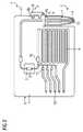
図1には覆いのない平板体1の前面7の平面図とEカップ(カップ状容器)5の断面図とが示されている。平板体1はチップカードの形状もしくはクレジットカードの形状に形成されている。このようなチップカードの寸法関係の値は、例えば高さH×幅B×厚さDが、5.5cm×8.5cm×0.1cmに等しい。前面7には、マイクロ流体装置3,4が平板体1内の窪みとして形成されている。平板体1は、例えばプラスチック材料、特に射出成形プラスチックからなる。マイクロ流体装置3は、例えば通路9および室10であり、これらは、1mm〜5mmの範囲の幅と、約100μmの深さを有することができる。室は、例えば1mm〜10mmの長さを、そして通路は1cm〜100cmの範囲の長さを有することができる。マイクロ流体装置3内には試薬を、例えば乾燥された形で貯蔵することができる。
FIG. 1 shows a plan view of a
平板体1の裏面8側の切欠きは1.4cm×1.3cm×800μmの範囲の高さH’×幅B’×深さT’のサイズを有しており、この切欠きにはセンサチップ2が、例えば接着によって固定されている。センサチップ2はその一面側にセンサアレイを有し、その他面側にセンサチップ2の読み取りのための電気接触部を有している。このセンサチップ2は、前記切欠き内に、センサチップ2のセンサアレイ側の面が、反応および/または検出室として使用されるマイクロ流体室10’の底を形成するように配置されている。センサチップ2の電気接触部側の面は平板体1の裏面8と共に1つの平面を形成している。センサアレイのセンサは、マイクロ流体室10’内に存在する液体中の光学的又は電気化学的な物質又は反応生成物を検出する。センサの電気信号は、センサチップ2の電気接触部を介して外部の測定およびデータ処理装置に送信することができ、又はセンサチップ2上の集積回路によって処理して直接表示するか、又は前記電気接触部を介して伝送することができる。 The notch on the
試料準備、例えば細胞の溶解および/または検出反応のために使用される液体は、供給および排出開口12およびマイクロ流体通路9を介してマイクロ流体装置3,9,10,10’に供給することができる。その供給の制御は、平板体1内に形成されている弁11を介して行なうことができる。空気のような流体も供給および排出開口12を介して平板体に供給し、又は平板体から取り出すことができ、その際にマイクロ流体装置3,9,10,10’内に過圧もしくは負圧が発生させられる。 Liquid used for sample preparation, for example cell lysis and / or detection reactions, may be supplied to the
本発明に従って、平板体1は、平らにされたピペットの形状および機能を有する第2のマイクロ流体装置4を含む。この第2のマイクロ流体装置4は、平板体と一体的に例えばプラスチックから一緒に作られている。その長さLは、使用されるEカップ5の大きさに依存して2.5cmの範囲にあるとよい。その長さは、ほぼEカップ5の深さ、即ちEカップ5の開口15から底14までの間隔であるべきである。それによって、第2のマイクロ流体装置4によりEカップ5から液体をほぼ全部取り出すことができる。第2のマイクロ流体装置4の厚さは平板体の厚さ、例えば1mmに等しい。平板体1の前面7において第2のマイクロ流体装置4の中心には通路9’が窪みとして形成されており、この通路9’は残りの平板体1における第1のマイクロ流体装置3の通路9の大きさにほぼ一致している。従って、通路9’の幅は1mmの範囲にあり、通路9’の深さは100μmの範囲にある。通路9’は通路9および/または室10を介してセンサチップ2のセンサに流体的に接続されている。第2のマイクロ流体装置4の幅は、例えば2mmである。 In accordance with the present invention, the plate 1 includes a second
平板体1の固定装置6aを介してEカップ5は平板体1にクランプ支持により固定することができる。図1にはEカップの断面が示されている。Eカップ5として、例えば1ml〜100mlの範囲の液体体積を収容する「Eppis」の形の反応容器を使用するとよい。液体としてEカップ5中に、例えば血液、尿、雑用水又は飲料水のような検査すべき液体が入っている。この液体が検査のためにEカップ内に準備されるとよい。例えば細胞が溶解され、DNAが複製され、標識が結合され、および/またはビーズを介してEカップ5内の特定の分子の取り出しもしくは濃縮が行なわれる。代替として、検査すべき液体が処理されないで第2のマイクロ流体装置4を介して平板体1の中に導入されてもよい。Eカップ中には、液体として、検査すべき液体の代わりに、検査に関与する物質が入っていてもよい。 The
第2のマイクロ流体装置4は、第1のマイクロ流体装置3と流体的に接続されており、第1のマイクロ流体装置3内の毛管作用力又は負圧により、液体がEカップ5から第2のマイクロ流体装置4を介して第1のマイクロ流体装置3に入ってセンサチップ2のセンサアレイに達するように、Eカップ5の中に挿入される。第1マイクロ流体装置3内の過圧により、液体を第1マイクロ流体装置3から第2のマイクロ流体装置4を介してEカップ5の中に導入することができる。例えば多くの溶液体積を必要とし、この理由からマイクロ流体装置3内では実施することができない化学反応は、「別の所にある」Eカップ内で行なうとよい。その後で反応生成物を平板体1内で後処理するか、又は直接的にセンサを介して検出することができる。 The second
Eカップ5を平板体1に接続して簡単に操作するために、固定装置6aを第2マイクロ流体装置4の幅拡張部として形成するとよい。これは、固定装置6aを、第2のマイクロ流体装置4を含めて平板体1と一緒に射出成形プラスチックからなる一体ものとして一工程にて簡単に低コストで製造することを可能にする。マイクロ流体装置3,4はフィルムにより密閉されている。例えば、自己粘着性フィルムおよび/または接着されたフィルムが第1および第2のマイクロ流体装置3,4を含めて平板体1の前面7を完全に覆うとよい。代替として部分的又は全体的に平板体1上に熱で溶着するフィルムを配設してもよい。開口12は、必要なときに針によって突き刺して開けるとよい。第2のマイクロ流体装置4の先端13の開口も同様に必要なときに裂いて開けるか、切って開けるか、又は突き刺して開けるとよい。あるいは代替として平板体1上にフィルムを形成する際に先端13に開口を形成してもよい。 In order to connect the
固定装置6aは、Eカップの開口15の内径にほぼ一致する幅、又は僅かに例えば約1mmだけ大きい幅を有する。固定装置の最も簡単な形状は矩形、特に丸みのある角を有する矩形である。固定装置6aに被せてEカップ5を押し込んだ際に、2つの対向する縁部が開口15の領域におけるEカップの内壁を押圧する。摩擦が平板体1、特に平板体1の固定装置6aへのEカップ5の機械的固定を生じる。固定装置6aが、2つの対向する縁が凸状に膨らんだ樽断面の輪郭を有する場合にも、固定装置6aに被せてEカップ5を簡単に押し込むことができる。簡略化のために、図1には固定装置6aの矩形の形しか示されていない。固定装置の厚さは残りの平板体1の厚さに等しいか、又はほぼ等しい。 The fixing
図2には固定装置6aおよび固定装置6bを備えた平板体1の実施例が示されている。固定装置6aは既述の固定装置6aと類似している。付加的に平板体1にはEカップの蓋を固定するための固定装置6bが形成されている。固定装置6bは、第2マイクロ流体装置4に隣接した平板体1の1つの縁部17における2つの切欠きから構成されている。これらの切欠きは、Eカップ5の蓋を閉めた際にEカップ5の方に向く蓋下部とは逆の形状および寸法関係を有する。 FIG. 2 shows an embodiment of the flat plate 1 having the fixing
固定装置6bは、Eカップ5と平板体1との改善された機械的接続と、Eカップ5および平板体1の高められた安定性とをもたらす。Eカップ5と関連した平板体1の簡単な操作が可能にされる。第2のマイクロ流体装置4を介する平板体1とEカップ5との間の液体交換が、とりわけ平板体1の供給および排出開口12を介する外部ポンプの接続時に可能にされる。Eカップ5は、平板体1に接続して、検査すべき液体又は反応に関与する液体を供給するための試料容器として、外部の反応容器として、又は廃棄処理すべき液体のための廃棄物容器として使用することができる。 The fixing
500μlの可能な液体体積を有するEカップ5を使用する場合、Eカップ5の全長は30mmであり、Eカップ5の内部空間の長さは29mmである。Eカップ5の外径は7.6mmである。しかし、つばの形を有するEカップ5の丸い上縁の10mmの外径と6.5mmの内径とが、固定装置6aの寸法にとって決定的に重要である。それゆえ固定装置6aは、この実施例では、同様に6.5mmの範囲の幅、又は僅かに大きい例えば6.6mmの範囲の幅を有する。それによってEカップ5を押し込んだ際にクランプ作用による機械的固定が達成される。固定装置6aの先端13に比べて残りの平板体1への固定装置6aの移行部の距離は、Eカップ5の内部空間の29mmの長さか、又はそれよりも僅かに短い。それによって、残りの平板体1への固定装置6aの移行部のストッパまでEカップを押し込んだ際には、先端13がEカップ5の底14の領域に位置する。従って第2のマイクロ流体装置4によってEカップ5内の全液体を取り扱うことができる。固定装置6a上にEカップ5を完全に押し込まないときには、固定装置6aの先端13に対する残りの平板体1への固定装置6aの移行部の間隔の長さが29mmよりも長く形成されていてもよい。Eカップ5の液体体積全体を使用する又は取り扱う必要がない場合、その長さは29mmよりも短くてもよい。 When using the
1 平板体
2 センサチップ
3 第1のマイクロ流体装置
4 第2のマイクロ流体装置
5 Eカップ
6a 固定装置
6b 固定装置
7 前面
8 裏面
9 通路
9’ 通路
10 室
10’ マイクロ流体室
11 弁
12 供給および排出開口
13 先端
14 底
15 開口
16 蓋
17 縁部DESCRIPTION OF SYMBOLS 1 Flat body 2 Sensor chip 3 1st
Claims (13)
Translated fromJapanese平板体(1)が、この平板体(1)にカップ状容器(5)を直接に機械的に固定するための固定装置(6a)を含み、
この固定装置(6a)が第2のマイクロ流体装置(4)の一部として形成され、
平板体(1)がプラスチック材料からなり、
固定装置(6a)が、第2のマイクロ流体装置(4)を含めて平板体(1)のプラスチック材料から一体的に製作されている
ことを特徴とする平板体。A chip card-like flat plate (1) for biochemical analysis of a substance, comprising at least two microfluidic devices (3, 4) and at least one sensor chip (2), wherein at least one sensor chip (2) is incorporated into the plate (1) and directly contacts at least one first microfluidic device (3),and the plate (1) pipette-like second microfluidic device (4). Ina flat plate thatincludes integrally,
The flat plate (1) includes a fixing device (6a) for directly and mechanically fixing the cup-shaped container (5) to the flat plate (1).
This fixing device (6a) is formed as part of the second microfluidic device (4),
The flat plate (1) is made of a plastic material,
The flat plate body, wherein the fixing device (6a) is integrally made of the plastic material of the flat plate body (1) including the second microfluidic device (4) .
平板体(1)の前面(7)の平らな面に窪みとして形成された通路(9,9')および室(10,10')を含み、
かつ、平板体(1)内に形成された弁(11)を含み、
かつ、平板体(1)の裏面(8)の平らな面に窪みとして形成されかつその中にセンサチップ(2)が埋設された切欠きを含み、
そのセンサチップ(2)が、平板体(1)の裏面(8)の平らな面を有する1つの面内にある電気接触部、または平板体(1)の前面(7)における少なくとも1つの室(10')に直接接触しているセンサアレイを有することを特徴とする請求項1乃至4の1つに記載の平板体。At least two microfluidic devices (3, 4) are
Including a passage (9, 9 ') and a chamber (10, 10') formed as a depression in the flat surface of the front surface (7) of the flat plate (1),
And including a valve (11) formed in the flat plate (1),
And a notch in which a flat surface of the back surface (8) of the flat plate (1) is formed as a depression and the sensor chip (2) is embedded therein,
At least one chamber in which the sensor chip (2) is in one surface having a flat surface of the back surface (8) of the flat plate (1) or the front surface (7) of the flat plate (1) plate members according to one of claims 1 to4, characterized in that it comprises a sensor array that is in direct contact with the (10 ').
センサチップ(2)が、センサの電気信号を処理するための集積回路、またはセンサチップ(2)を電気的に読み取るための電気接触部を含むことを特徴とする請求項1乃至8の1つに記載の平板体。The sensor chip (2) comprises an array of electrochemical sensors;
Sensor chip (2) is one of the claims 1 to8, characterized in that it comprises an electrical contact portion for reading an integrated circuit for processing the electrical signals of the sensor or the sensor chip (2), the electrical The flat plate described in 1.
検査すべき液体をカップ状容器(5)に充填するステップ、
そのカップ状容器(5)の中に第2のマイクロ流体装置(4)を挿入して、第2のマイクロ流体装置(4)を検出すべき液体に直接に接触させるステップ、
その液体を第2のマイクロ流体装置(4)を通して第1のマイクロ装置(3)の中に移送するステップ、
検査すべき液体をセンサチップ(2)の上に導くステップ、
センサチップ(2)の少なくとも1つのセンサが、検査すべき液体の少なくとも1つの化学的または生化学的な物質、または検査すべき液体の物質の反応生成物と相互作用するステップ
を含むことを特徴とする平板体の使用方法。A method of using a flat body (1) according to one of claims 1 to10 , wherein the method comprises the following steps:
Filling the cup-like container (5) with the liquid to be examined;
Inserting a second microfluidic device (4) into the cup-like container (5) and bringing the second microfluidic device (4) into direct contact with the liquid to be detected;
Transferring the liquid through the second microfluidic device (4) into the first microdevice (3);
Guiding the liquid to be examined on the sensor chip (2);
At least one sensor of the sensor chip (2) comprising interacting with at least one chemical or biochemical substance of the liquid to be examined or a reaction product of the substance of the liquid to be examined How to use the flat plate.
Applications Claiming Priority (3)
| Application Number | Priority Date | Filing Date | Title |
|---|---|---|---|
| DE102009043226ADE102009043226B4 (en) | 2009-09-28 | 2009-09-28 | Flat body in the manner of a chip card for biochemical analysis and method for its use |
| DE102009043226.4 | 2009-09-28 | ||
| PCT/EP2010/064258WO2011036289A1 (en) | 2009-09-28 | 2010-09-27 | Flat body in the manner of a chip card for biochemical analysis and method for the use thereof |
Publications (2)
| Publication Number | Publication Date |
|---|---|
| JP2013506123A JP2013506123A (en) | 2013-02-21 |
| JP5430766B2true JP5430766B2 (en) | 2014-03-05 |
Family
ID=43302368
Family Applications (1)
| Application Number | Title | Priority Date | Filing Date |
|---|---|---|---|
| JP2012530287AExpired - Fee RelatedJP5430766B2 (en) | 2009-09-28 | 2010-09-27 | Chip card plate for biochemical analysis and method of use thereof |
Country Status (7)
| Country | Link |
|---|---|
| US (1) | US9415390B2 (en) |
| EP (1) | EP2482982B1 (en) |
| JP (1) | JP5430766B2 (en) |
| CN (1) | CN102548659B (en) |
| BR (1) | BR112012006831B1 (en) |
| DE (1) | DE102009043226B4 (en) |
| WO (1) | WO2011036289A1 (en) |
Families Citing this family (8)
| Publication number | Priority date | Publication date | Assignee | Title |
|---|---|---|---|---|
| DE102009043226B4 (en) | 2009-09-28 | 2012-09-27 | Siemens Aktiengesellschaft | Flat body in the manner of a chip card for biochemical analysis and method for its use |
| EP2514528A1 (en)* | 2011-04-19 | 2012-10-24 | Cellix Limited | Device and method for assessing the status of cells in a biological fluid |
| WO2013082316A1 (en)* | 2011-11-29 | 2013-06-06 | Caliper Life Sciences, Inc. | Systems and methods for sampling of amplification products |
| US9689029B2 (en) | 2011-12-02 | 2017-06-27 | Caliper Life Sciences, Inc. | Systems and methods for sampling of amplification products |
| SG11201402709WA (en)* | 2011-12-06 | 2014-06-27 | Univ Bruxelles | Method and device for assaying an antigen present on erythrocytes or an antibody binding to an antigen present on erythrocytes |
| CN104178413B (en)* | 2014-07-04 | 2016-05-25 | 宁波美晶医疗技术有限公司 | A kind of plastic packaging box packaging structure of rare cell separator |
| CN106501499B (en) | 2015-09-07 | 2019-12-17 | 埃克西亚斯医药有限公司 | Movable measuring unit |
| CN110624615B (en)* | 2019-09-19 | 2024-08-06 | 深圳富士凯烨医疗电子科技有限公司 | Microfluidic chip |
Family Cites Families (21)
| Publication number | Priority date | Publication date | Assignee | Title |
|---|---|---|---|---|
| US5747666A (en)* | 1997-03-26 | 1998-05-05 | Willis; John P. | Point-of-care analyzer module |
| US5804437A (en) | 1997-08-19 | 1998-09-08 | Biomerieux Vitek, Inc. | Locking structure for securing a fluid transfer tube |
| DE19846466A1 (en)* | 1998-10-08 | 2000-04-27 | Ghs Gesundheits Service Ag | Analysis method for the simultaneous determination of parameters from different media |
| DE19947495C2 (en) | 1999-10-01 | 2003-05-28 | Agilent Technologies Inc | Microfluidic microchip |
| CN1117284C (en) | 1999-10-27 | 2003-08-06 | 陆祖宏 | Microfluid biochip detection-analysis board and its detection method |
| US20020009392A1 (en) | 2000-03-28 | 2002-01-24 | Wolk Jeffrey A. | Methods of reducing fluid carryover in microfluidic devices |
| DE10111458B4 (en) | 2001-03-09 | 2008-09-11 | Siemens Ag | analyzer |
| US6913933B2 (en)* | 2001-12-03 | 2005-07-05 | Ortho-Clinical Diagnostics, Inc. | Fluid dispensing algorithm for a variable speed pump driven metering system |
| US7524464B2 (en)* | 2003-09-26 | 2009-04-28 | Ahn Chong H | Smart disposable plastic lab-on-a-chip for point-of-care testing |
| US8323564B2 (en) | 2004-05-14 | 2012-12-04 | Honeywell International Inc. | Portable sample analyzer system |
| DE102005049976A1 (en)* | 2004-10-15 | 2006-04-20 | Siemens Ag | Cartridge card for automated DNA or protein analysis has a geometric array of micro-channels with dry reagents |
| US20060165558A1 (en) | 2004-12-21 | 2006-07-27 | Thomas Witty | Cartridge for diagnostic assays |
| US8206650B2 (en)* | 2005-04-12 | 2012-06-26 | Chromedx Inc. | Joint-diagnostic spectroscopic and biosensor meter |
| WO2007021809A2 (en) | 2005-08-11 | 2007-02-22 | Eksigent Technologies, Llc | Microfluidic systems, devices and methods for reducing background autofluorescence and the effects thereof |
| WO2008002483A2 (en)* | 2006-06-23 | 2008-01-03 | Mcneely Michael R | Reagent preparation and valving design for liquid testing |
| CN101479609B (en) | 2006-06-30 | 2012-09-05 | 松下电器产业株式会社 | Analysis panel and analysis device using same |
| JP2008175608A (en)* | 2007-01-17 | 2008-07-31 | Yokogawa Electric Corp | Chemical reaction cartridge and method of use thereof |
| WO2009117167A1 (en) | 2008-01-02 | 2009-09-24 | Blood Cell Storage, Inc. | Devices and processes for nucleic acid extraction |
| US20090186344A1 (en)* | 2008-01-23 | 2009-07-23 | Caliper Life Sciences, Inc. | Devices and methods for detecting and quantitating nucleic acids using size separation of amplicons |
| GB0805296D0 (en)* | 2008-03-20 | 2008-04-30 | Iti Scotland Ltd | Uses of reagents in sample collection and cartridge systems |
| DE102009043226B4 (en) | 2009-09-28 | 2012-09-27 | Siemens Aktiengesellschaft | Flat body in the manner of a chip card for biochemical analysis and method for its use |
- 2009
- 2009-09-28DEDE102009043226Apatent/DE102009043226B4/ennot_activeExpired - Fee Related
- 2010
- 2010-09-27JPJP2012530287Apatent/JP5430766B2/ennot_activeExpired - Fee Related
- 2010-09-27USUS13/498,871patent/US9415390B2/ennot_activeExpired - Fee Related
- 2010-09-27BRBR112012006831Apatent/BR112012006831B1/ennot_activeIP Right Cessation
- 2010-09-27EPEP10760321.9Apatent/EP2482982B1/ennot_activeNot-in-force
- 2010-09-27WOPCT/EP2010/064258patent/WO2011036289A1/enactiveApplication Filing
- 2010-09-27CNCN201080043136.0Apatent/CN102548659B/ennot_activeExpired - Fee Related
Also Published As
| Publication number | Publication date |
|---|---|
| EP2482982A1 (en) | 2012-08-08 |
| BR112012006831A8 (en) | 2017-12-05 |
| DE102009043226A1 (en) | 2011-03-31 |
| US20120184043A1 (en) | 2012-07-19 |
| JP2013506123A (en) | 2013-02-21 |
| BR112012006831B1 (en) | 2020-02-04 |
| US9415390B2 (en) | 2016-08-16 |
| WO2011036289A1 (en) | 2011-03-31 |
| EP2482982B1 (en) | 2017-08-16 |
| DE102009043226B4 (en) | 2012-09-27 |
| CN102548659A (en) | 2012-07-04 |
| CN102548659B (en) | 2016-12-07 |
| BR112012006831A2 (en) | 2016-06-07 |
Similar Documents
| Publication | Publication Date | Title |
|---|---|---|
| JP5430766B2 (en) | Chip card plate for biochemical analysis and method of use thereof | |
| US12385933B2 (en) | Cartridges and instruments for sample analysis | |
| JP4546534B2 (en) | Comprehensive and automatic analyzer for DNA or protein in a disposable cartridge, method for manufacturing such cartridge, and operating method for DNA or protein analysis using such cartridge | |
| US10184946B2 (en) | Method for operating a system for the integrated and automated analysis of DNA or protein | |
| JP4249983B2 (en) | Analysis equipment | |
| US7482585B2 (en) | Testing chip and micro integrated analysis system | |
| JP5675592B2 (en) | Titer plate and detection method of analysis target | |
| JP4721414B2 (en) | REACTION CARTRIDGE, REACTOR, AND METHOD FOR TRANSFERRING REACTION CARTRIDGE SOLUTION | |
| JP5318963B2 (en) | Reagent container pack | |
| US9726680B2 (en) | Reaction vessel, assay device, and measuring method | |
| US20140160877A1 (en) | Method for mixing at least one sample solution having at least one reagent, and device | |
| JP2018205047A (en) | Specimen processing chip, liquid feeder of specimen processing chip, and liquid feeding method | |
| US10816563B2 (en) | System for operating a system for the integrated and automated analysis of DNA or protein | |
| US20250033041A1 (en) | Reagent pre-embedding and sample injecting device, and sample injection method therefor and application thereof | |
| JP5368574B2 (en) | Device for the preparation and / or processing of biological samples | |
| JP2006017732A (en) | Equipment for reliable analysis | |
| JPWO2008096570A1 (en) | Microchip and microchip inspection system | |
| US11867653B2 (en) | Systems and methods for mounting biosensors using a consumable fluid reservoir | |
| WO2009113487A1 (en) | Micro inspection chip and method of dividing liquid for micro inspection chip | |
| CA3203372A1 (en) | Chemical processing system, instrument and sample cartridge | |
| US10751714B2 (en) | Cartridge for testing a sample | |
| JP2001161342A (en) | Holding base for microtube | |
| WO2022136248A1 (en) | Analysis system for testing a sample | |
| JP2006025693A (en) | Sequential transfer reaction tank, manufacturing method of sequential transfer reaction tank, and test method using sequential transfer reaction tank |
Legal Events
| Date | Code | Title | Description |
|---|---|---|---|
| A977 | Report on retrieval | Free format text:JAPANESE INTERMEDIATE CODE: A971007 Effective date:20130524 | |
| A131 | Notification of reasons for refusal | Free format text:JAPANESE INTERMEDIATE CODE: A131 Effective date:20130604 | |
| A521 | Request for written amendment filed | Free format text:JAPANESE INTERMEDIATE CODE: A523 Effective date:20130902 | |
| TRDD | Decision of grant or rejection written | ||
| A01 | Written decision to grant a patent or to grant a registration (utility model) | Free format text:JAPANESE INTERMEDIATE CODE: A01 Effective date:20131105 | |
| A61 | First payment of annual fees (during grant procedure) | Free format text:JAPANESE INTERMEDIATE CODE: A61 Effective date:20131203 | |
| R150 | Certificate of patent or registration of utility model | Free format text:JAPANESE INTERMEDIATE CODE: R150 Ref document number:5430766 Country of ref document:JP Free format text:JAPANESE INTERMEDIATE CODE: R150 | |
| S111 | Request for change of ownership or part of ownership | Free format text:JAPANESE INTERMEDIATE CODE: R313113 | |
| R350 | Written notification of registration of transfer | Free format text:JAPANESE INTERMEDIATE CODE: R350 | |
| R250 | Receipt of annual fees | Free format text:JAPANESE INTERMEDIATE CODE: R250 | |
| R250 | Receipt of annual fees | Free format text:JAPANESE INTERMEDIATE CODE: R250 | |
| R250 | Receipt of annual fees | Free format text:JAPANESE INTERMEDIATE CODE: R250 | |
| R250 | Receipt of annual fees | Free format text:JAPANESE INTERMEDIATE CODE: R250 | |
| R250 | Receipt of annual fees | Free format text:JAPANESE INTERMEDIATE CODE: R250 | |
| R250 | Receipt of annual fees | Free format text:JAPANESE INTERMEDIATE CODE: R250 | |
| LAPS | Cancellation because of no payment of annual fees |