JP5426149B2 - Non-contact power transmission device - Google Patents
Non-contact power transmission deviceDownload PDFInfo
- Publication number
- JP5426149B2 JP5426149B2JP2008304533AJP2008304533AJP5426149B2JP 5426149 B2JP5426149 B2JP 5426149B2JP 2008304533 AJP2008304533 AJP 2008304533AJP 2008304533 AJP2008304533 AJP 2008304533AJP 5426149 B2JP5426149 B2JP 5426149B2
- Authority
- JP
- Japan
- Prior art keywords
- power
- wireless communication
- unit
- power transmission
- coil
- Prior art date
- Legal status (The legal status is an assumption and is not a legal conclusion. Google has not performed a legal analysis and makes no representation as to the accuracy of the status listed.)
- Expired - Fee Related
Links
- 230000005540biological transmissionEffects0.000titleclaimsdescription137
- 238000004891communicationMethods0.000claimsdescription145
- 230000005674electromagnetic inductionEffects0.000claimsdescription10
- 230000004913activationEffects0.000claimsdescription2
- 238000010586diagramMethods0.000description11
- 238000000034methodMethods0.000description5
- 238000006243chemical reactionMethods0.000description4
- 230000009467reductionEffects0.000description2
- 230000004044responseEffects0.000description2
- 239000013585weight reducing agentSubstances0.000description2
- 230000008859changeEffects0.000description1
- 238000011109contaminationMethods0.000description1
- 238000012937correctionMethods0.000description1
- 230000008878couplingEffects0.000description1
- 238000010168coupling processMethods0.000description1
- 238000005859coupling reactionMethods0.000description1
- 230000005669field effectEffects0.000description1
- 238000012986modificationMethods0.000description1
- 230000004048modificationEffects0.000description1
- 230000002093peripheral effectEffects0.000description1
Images


Landscapes
- Charge And Discharge Circuits For Batteries Or The Like (AREA)
Description
Translated fromJapanese本発明は、非接触で電力を送受電する非接触電力伝送装置に関するものである。 The present invention relates to a contactless power transmission device that transmits and receives power without contact.
近年、電子部品の小型化に伴い、携帯電話や携帯型音楽プレーヤ等に代表される携帯電子機器は、小型化や軽量化が図られ、広く普及してきている。更に近年、携帯電子機器は、多機能化及び高速処理化が図られ、それに伴い電子機器が必要とする電力量が増加傾向にある。しかし、一般に、携帯電子機器は、専用のアダプターを内蔵せず、内蔵した2次電池に充電した電力により駆動しており、2次電池の電力が不足する度に2次電池に充電しなければならない。 In recent years, along with the downsizing of electronic components, portable electronic devices typified by mobile phones and portable music players have been widely spread due to the reduction in size and weight. In recent years, portable electronic devices have become more multifunctional and faster, and accordingly, the amount of power required by the electronic devices has been increasing. However, in general, portable electronic devices do not have a dedicated adapter and are driven by the power charged in the built-in secondary battery, and the secondary battery must be charged each time the power of the secondary battery is insufficient. Don't be.
一般に、携帯電子機器の2次電池への充電は、携帯電子機器の充電端子と充電台(クレードル)の充電端子を接触させ、電気的に接続し、充電台から電力を供給して内蔵する2次電池に充電する。 In general, the charging of the secondary battery of the portable electronic device is performed by bringing the charging terminal of the portable electronic device and the charging terminal of the charging base (cradle) into contact, electrically connecting them, and supplying power from the
しかしながら、充電端子同士を接触して接続する充電方式では、充電端子の汚れや、充電端子間への異物侵入により充電ができない場合があり、非接触での電力供給が望まれている。 However, in the charging method in which the charging terminals are connected in contact with each other, charging may not be possible due to contamination of the charging terminals or entry of foreign matter between the charging terminals, and non-contact power supply is desired.
この要望に対し、充電端子を用いずに非接触で電力を供給し、携帯電子機器に内蔵する2次電池に充電を行う送電装置、及び受電装置が特許文献1に開示されている。 In response to this demand,
特許文献1に記載の送電装置及び受電装置は、共用クレードルは内部にコイルを含む送電モジュールを備えるとともに商用電圧が供給されており、PDAは内部にコイルを含む受電モジュールを備えている。PDAを共用クレードル上に載置することで、PDA内のコイルと共用クレードル内のコイルとの間で磁気結合が発生して、共用クレードルに供給される商用電圧に基づいてPDA内のコイルの両端に電圧が誘起され、PDAに電力が供給される。このとき、共用クレードルとPCとの間でデータ通信可能である構成とすることで、PCとPDAとの間でデータ伝送を行うことができる。 In the power transmission device and the power reception device described in
送電装置と受電装置間で電力の送受電に関する情報を相互にやりとりする必要がある場合は、特許文献1に記載のように、無線通信を用いて情報の授受をする手段を、コイルの電磁誘導を利用して電力を送受電する装置に備えていることがある。 When it is necessary to exchange information regarding power transmission / reception between the power transmission device and the power reception device, as described in
更に、携帯する側の装置である受電装置は、できるだけ小型で軽量であることが望まれ、例えば、電力受電用のコイルと無線通信用のコイルとを兼用して、装置の部品数を減らし、小型化及び軽量化を図ることができる。 Furthermore, the power receiving device that is the device on the portable side is desired to be as small and light as possible. For example, the power receiving coil and the wireless communication coil are combined to reduce the number of parts of the device. A reduction in size and weight can be achieved.
電力受電用のコイルと無線通信用のコイルとを兼用する場合、例えば、特許文献1に記載の様に、電力を供給する電力波もしくは搬送波に、電力の送受電に関する情報からなる信号を重畳または変調して送受信することで、電力と通信を同時に行う方法と、電力を送受電する電力波と無線通信する搬送波を併用し、電力の送受電中に同時に無線通信を行う方法がある。 When using both a power receiving coil and a wireless communication coil, for example, as described in
しかしながら、電力波もしくは搬送波に信号を重畳または変調する方法において、一般に、電力を供給する為には、電力波もしくは搬送波の出力を大きくする必要があり、同一の送電装置及び受電装置が近傍にある場合、近傍の装置との混信等が発生する可能性があり、無線通信が正常に行えなくなる場合があるという課題がある。 However, in a method of superimposing or modulating a signal on a power wave or carrier wave, in general, in order to supply power, it is necessary to increase the output of the power wave or carrier wave, and the same power transmission device and power receiving device are in the vicinity. In this case, there is a possibility that interference with nearby devices may occur, and wireless communication may not be performed normally.
上記課題に対して、電力を送受電する電力波と無線通信する搬送波を併用する方法であれば、電力を供給する電力波の出力のみを高くし、無線通信を行う搬送波の出力は低く抑えることができ、同一の送電装置及び受電装置が近傍にある場合でも、正常に無線通信が行える。 In response to the above problem, if the power wave for transmitting and receiving power and the carrier wave for wireless communication are used in combination, only the output of the power wave for supplying power is increased, and the output of the carrier wave for wireless communication is kept low. Even when the same power transmitting device and power receiving device are in the vicinity, wireless communication can be normally performed.
しかしながら、電力を送受電する電力波と無線通信する搬送波を併用する方法において、一般に、送受電する電力波の出力に比べて無線通信で送受信する信号出力が小さい為に、装置内部の回路で、電力波によるノイズ成分に信号成分が埋没してしまい、正しく無線通信ができなくなる可能性があるという課題がある。 However, in the method of using both the power wave for transmitting and receiving power and the carrier wave for wireless communication, in general, since the signal output to be transmitted and received by wireless communication is smaller than the output of the power wave to transmit and receive power, There is a problem that a signal component is buried in a noise component caused by a power wave, and wireless communication cannot be performed correctly.
本発明の目的は、上記課題を解決し、小型化及び軽量化を図るとともに、送受電する電力波の影響を受けずに正しく無線通信ができ、且つ非接触による電力の送受電ができる非接触電力伝送装置を提供することである。 The object of the present invention is to solve the above-mentioned problems, achieve miniaturization and weight reduction, perform wireless communication correctly without being affected by the power wave to be transmitted and received, and contactlessly transmit and receive power without contact It is to provide a power transmission device.
本発明によれば、無線通信によって制御情報の授受を行うとともに、電磁誘導によって電力の送受電を行う電力送電手段及び電力受電手段を有する非接触電力伝送装置であって、前記電力送電手段は、前記電力受電手段との無線通信を行う第1のコイルに接続された第1の無線通信部と、電磁誘導により前記電力受電手段への電力の送電を行う第2のコイルに接続された電力送電部と、前記第1の無線通信部による無線通信及び前記電力送電部による電力の送電をそれぞれ開始または停止する制御を行う第1の制御部を備え、前記電力受電手段は、前記電力送電手段との無線通信及び電力の受電に用いる第3のコイルと、前記電力送電手段との無線通信を行う第2の無線通信部と、前記電力送電手段からの電力の受電を行う電力受電部と、前記第2の無線通信部または前記電力受電部のいずれか一方に切り替えて前記第3のコイルと接続するコイル接続切替部と、前記第2の無線通信部による無線通信及び前記電力受電部による電力の送電をそれぞれ開始または停止する制御ならびに、前記コイル接続切替部による前記第3のコイルとの接続の制御を行う第2の制御部を備え、前記電力送電手段と前記電力受電手段との間で予め定めた時間間隔毎に無線通信を行い、無線通信中は前記電力送電手段と前記電力受電手段との電力送受電を中止し、無線通信の終了後に前記電力送電手段と前記電力受電手段との電力送受電を再開するよう構成され、前記第1の制御部が、前記電力送電手段の起動後に送電可能信号を生成し、前記第1の無線通信部に入力し、前記第1のコイルを介して前記電力受電手段へ送信し、前記第2の制御部が、前記第3のコイルを介して前記第2の無線通信部から入力された送電可能信号の有無の判断を行い、前記送電可能信号が無い場合には、受信状態を維持し、前記送電可能信号が有る場合には、続いて充電要求信号の有無の判断を行い、前記充電要求信号が無い場合には、充電を停止し、前記充電要求信号が有る場合には、前記充電要求信号を前記第2の無線通信部に入力し、前記第3のコイルを介して前記電力送電手段へ送信し、前記第1の制御部が、前記第1のコイルを介して前記第1の無線通信部から入力された充電要求信号の有無の判断を行い、前記充電要求信号が有る場合には、前記第1の無線通信部の無線通信を停止し、前記電力受電手段への電力の送電を開始し、前記充電要求信号が無い場合には、再度前記第1の無線通信部に前記送電可能信号を入力し、前記第1のコイルを介して前記電力受電手段へ送信し、前記電力送電手段が、予め定めた一定時間の間、連続して送電し、一定時間経過後前記電力送電部の送電を停止し、再度前記第1の無線通信部の無線通信を開始することを特徴とする非接触電力伝送装置が得られる。According to the present invention, there is provided a non-contact power transmission device having a power transmission unit and a power reception unit for performing transmission and reception of control information by wireless communication and transmitting and receiving power by electromagnetic induction, and the power transmission unit includes: A first wireless communication unit connected to a first coil that performs wireless communication with the power receiving unit, and a power transmission connected to a second coil that transmits power to the power receiving unit by electromagnetic induction And a first control unit that performs control to start or stop wireless communication by the first wireless communication unit and power transmission by the power transmission unit, and the power reception unit includes the power transmission unit and the first power transmission unit. A third coil used for wireless communication and power reception, a second wireless communication unit that performs wireless communication with the power transmission unit, a power reception unit that receives power from the power transmission unit, A coil connection switching unit that switches to either the second wireless communication unit or the power receiving unit and connects to the third coil, wireless communication by the second wireless communication unit, and power of the power receiving unit A control section for starting or stopping power transmission, and a second control section for controlling the connection with the third coil by the coil connection switching section, which is provided in advance between the power transmission section and the power reception section. Wireless communication is performed at predetermined time intervals, power transmission / reception between the power transmission unit and the power reception unit is stopped during the wireless communication, and power between the power transmission unit and the power reception unit is terminated after the wireless communication ends. The power transmission / reception isconfigured to resume, and the first control unit generates a power transmission enable signal after activation of the power transmission unit, inputs the signal to the first wireless communication unit, and passes through the first coil. Previous The power is transmitted to the power receiving means, and the second control unit determines whether there is a power transmittable signal input from the second wireless communication unit via the third coil, and the power transmittable signal is not present. In this case, the reception state is maintained, and if there is the signal that can be transmitted, it is determined whether or not there is a charge request signal. If there is no charge request signal, charging is stopped, and the charge request When there is a signal, the charging request signal is input to the second wireless communication unit and transmitted to the power transmission means via the third coil, and the first control unit is configured to transmit the first control unit to the first wireless communication unit. Determining whether or not there is a charge request signal input from the first wireless communication unit via the coil, and if there is the charge request signal, stop the wireless communication of the first wireless communication unit, Starting power transmission to the power receiving means, the charging request signal If there is no power, the power transmission enable signal is input again to the first wireless communication unit and transmitted to the power receiving means via the first coil. Is transmittedcontinuously, and after a certain period of time has elapsed, the power transmission of the power transmission unit is stopped, and the wireless communication of the first wireless communication unit is started again. .
図3は、本発明の非接触電力伝送装置を構成する電力送電手段と電力受電手段における電力の送受電、及び無線通信の動作タイミングを説明する図であり、図3(a)は、電力送電手段の第1の無線通信部を説明する図であり、図3(b)は、電力送電手段の電力送電部を説明する図であり、図3(c)は、電力受電手段の第2の無線通信部を説明する図であり、図3(d)は、電力受電手段の電力受電部を説明する図である。 FIG. 3 is a diagram for explaining the operation timing of power transmission / reception and wireless communication in the power transmission means and the power reception means constituting the non-contact power transmission apparatus of the present invention, and FIG. FIG. 3B is a diagram illustrating the power transmission unit of the power transmission unit, and FIG. 3C is a diagram illustrating the second wireless communication unit of the power reception unit. FIG. 3D is a diagram illustrating a wireless communication unit, and FIG. 3D is a diagram illustrating a power reception unit of a power reception unit.
図3をもとに、本発明による非接触電力伝送装置の電力送電手段と電力受電手段における無線通信及び電力送受電の動作タイミングを説明する。図3(a)に示す電力送電手段の第1の無線通信部は、第1の時間帯T1において第1の無線通信部の回路を駆動して無線通信を行い、第2の時間帯T2において第1の無線通信部の回路を停止して無線通信を行わない。更に、図3(b)に示す電力送電手段の電力送電部は、第1の時間帯T1において電力送電部の回路を停止して電力の送電を行わず、第2の時間帯T2において電力送電部の回路を駆動して電力の送電を行う。更に、図3(c)に示す電力受電手段の第2の無線通信部は、第1の時間帯T1において第2の無線通信部の回路を駆動して無線通信を行い、第2の時間帯T2において第2の無線通信部の回路を停止して無線通信を行わない。更に、図3(d)に示す電力受電手段の電力受電部は、第1の時間帯T1において電力受電部の回路を停止して電力の受電を行わず、第2の時間帯T2において電力受電部の回路を駆動して電力の受電を行う。つまり、電力送電手段と電力受電手段において、無線通信中に電力の送受電を行わない。または、電力の送受電中に無線通信を行わない。 Based on FIG. 3, operation timings of wireless communication and power transmission / reception in the power transmission unit and the power reception unit of the non-contact power transmission apparatus according to the present invention will be described. The first wireless communication unit of the power transmission means shown in FIG. 3A performs wireless communication by driving the circuit of the first wireless communication unit in the first time zone T1, and in the second time zone T2. The circuit of the first wireless communication unit is stopped and wireless communication is not performed. Further, the power transmission unit of the power transmission unit illustrated in FIG. 3B stops the power transmission unit circuit in the first time period T1 and does not transmit power, and does not transmit power in the second time period T2. Part of the circuit is driven to transmit power. Further, the second wireless communication unit of the power receiving means shown in FIG. 3C performs wireless communication by driving the circuit of the second wireless communication unit in the first time zone T1, and performs the second time zone. At T2, the circuit of the second wireless communication unit is stopped and wireless communication is not performed. Further, the power receiving unit of the power receiving unit shown in FIG. 3 (d) does not receive power by stopping the circuit of the power receiving unit in the first time zone T1, and receives power in the second time zone T2. Part of the circuit is driven to receive power. That is, the power transmission unit and the power reception unit do not transmit or receive power during wireless communication. Alternatively, wireless communication is not performed during power transmission / reception.
よって、コイル間の電磁誘導で電力の送受電を行う際に用いる出力が大きい電力波と、無線通信に用いるデータを重畳させた出力の小さな搬送波が、非接触電力伝送装置の電力送電手段及び電力受電手段の回路上に同時に存在することはなく、無線通信の信号成分が電力波のノイズ成分に埋没するのを防止でき、非接触電力伝送装置の電力送電手段及び電力受電手段間の無線通信を確実にすることができ、電磁誘導による電力の非接触送受電が可能となる。 Therefore, a power wave having a large output used when power is transmitted / received by electromagnetic induction between coils and a small carrier wave in which data used for wireless communication are superimposed are used as the power transmission means and power of the contactless power transmission device. It does not exist at the same time on the circuit of the power receiving means, and it is possible to prevent the signal component of the wireless communication from being buried in the noise component of the power wave, and the wireless communication between the power transmitting means and the power receiving means of the non-contact power transmission device. It can be ensured, and non-contact power transmission and reception by electromagnetic induction is possible.
更に、本発明によれば、無線通信に必要なコイルと電力の受電に必要なコイルを兼用することで、電力受電手段に設けるコイルを1つにすることができ、非接触電力伝送装置の小型化及び軽量化が可能となる。 Furthermore, according to the present invention, by combining the coil necessary for wireless communication and the coil necessary for power reception, the number of coils provided in the power receiving means can be reduced to one, and the contactless power transmission device can be reduced in size. And weight reduction are possible.
本発明によれば、電力の送受電に用いる電力波と、無線通信に用いるデータを重畳させた搬送波が、同一時間に同時に存在することがないので、電力波の影響を受けずに正しく無線通信ができ、更に、電力受電手段における電力の受電と無線通信を1つのコイルで行うことで、電力受電手段を構成する部品を減らすことができるので、電磁誘導による電力の非接触送受電ができる、小型で軽量な非接触電力伝送装置が得られる。 According to the present invention, since the power wave used for power transmission / reception and the carrier wave on which the data used for wireless communication are superimposed do not exist at the same time, wireless communication correctly without being affected by the power wave. In addition, by performing power reception and wireless communication in the power receiving means with one coil, it is possible to reduce the number of components constituting the power receiving means, so that non-contact power transmission and reception of power by electromagnetic induction can be performed. A small and lightweight contactless power transmission device can be obtained.
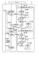
図1は、本発明の非接触電力伝送装置の実施の形態の構成を示すブロック図であり、図1をもとに、本発明の非接触電力伝送装置の各構成要素を説明する。 FIG. 1 is a block diagram showing a configuration of an embodiment of a non-contact power transmission apparatus according to the present invention. Each component of the non-contact power transmission apparatus according to the present invention will be described based on FIG.
本発明の非接触電力電送システムは、電力送電手段1及び電力受電手段2で構成される。 The non-contact power transmission system of the present invention includes a
電力送電手段1は、無線通信で情報を送受信し、電磁誘導で電力を送電する手段であり、電力送電部3、第1の無線通信部4a、第1の制御部5a、第1のコイル6a、第2のコイル6bにより構成され、電力送電部3と第1の制御部5a、電力送電部3と第2のコイル6b、第1の無線通信部4aと第1の制御部5a、第1の無線通信部4aと第1のコイル6aを各々電気的に接続する。 The
電力送電部3は、図示しないDC-AC変換回路を用いて、電力送電部3に供給する、図示しない直流電源から所定の交流の電力を生成して、第2のコイル6bに供給する。 The
第1の無線通信部4aは、第1の制御部5aから入力される送電可能信号を、図示しない変調回路で変調して搬送波に重畳し、第1のコイル6aへ入力する。 The first
また、第1の無線通信部4aは、電力受電手段2から送信される充電要求信号が重畳された搬送波を、図示しない復調回路で復調して充電要求信号を生成し、第1の制御部5aへ入力する。 The first
第1の制御部5aは、電力送電手段1の起動後に送電可能信号を生成し、第1の無線通信部4aに入力する。 The
また、第1の制御部5aは、第1の無線通信部4aから入力される充電要求信号の有無を判断し、充電要求信号が有る場合には、第1の無線通信部4aの無線通信動作を停止した後、電力送電部3及び第2のコイル6bを用いて電力受電手段2への電力の送電を開始し、充電要求信号が無い場合には、再び、第1の無線通信部4aに送電可能信号を入力した後、第1のコイル6aを用いて電力受電手段2へ送信する。 In addition, the
また、第1の制御部5aは、予め設定した一定時間毎に、第1の無線通信部4a及び第1のコイル6aを用いて電力受電手段2との無線通信を行い、無線通信を行っている間は電力送電部3及び第2のコイル6bによる電力受電手段2への電力の送電を中止し、無線通信終了後に電力送電部3及び第2のコイル6bによる電力受電手段2への電力の送電を再開する。 The
第1のコイル6aは、送電可能信号が重畳された搬送波を電力受電手段2に送信する。 The
また、第1のコイル6aは、充電要求信号が重畳された搬送波を電力受電手段2から受信し、第1の無線通信部4aへ入力する。 Further, the
第2のコイル6bは、電力送電部3から供給される交流の電力を電力波として電力受電手段2へ送電する。 The
電力受電手段2は、無線通信で情報を送受信し、電磁誘導で電力を得て2次電池に充電する手段であり、第2の無線通信部4b、第2の制御部5b、第3のコイル6c、コイル接続切替部7、電力受電部8、充電制御部9、2次電池10により構成され、第2の無線通信部4bとコイル接続切替部7、第2の無線通信部4bと第3のコイル6cの端子11a、第2の制御部5bとコイル接続切替部7、第2の制御部5bと電力受電部8、第2の制御部5bと充電制御部9、第3のコイル6cの端子11bとコイル接続切替部7、第3のコイル6cの端子11aと電力受電部8、コイル接続切替部7と電力受電部8、電力受電部8と充電制御部9、充電制御部9と2次電池10、の各々を電気的に接続する。更に、第3のコイル6cの端子11aを接地する。 The power receiving means 2 is means for transmitting and receiving information by wireless communication, obtaining power by electromagnetic induction and charging the secondary battery, and includes a second
第2の無線通信部4bは、受信した電力送電手段1からの送電可能信号が重畳された搬送波を図示しない復調回路で復調し、送電可能信号を生成して、第2の制御部5bへ入力する。 The second
また、第2の無線通信部4bは、第2の制御部5bから入力される充電要求信号を、図示しない変調回路で変調して搬送波に重畳し、第3のコイル6cへ入力する。 The second
第2の制御部5bは、第2の無線通信部4bから入力される送電可能信号の有無の判断を行い、送電可能信号が無ければ受信状態を維持し、送電可能信号が有れば充電制御部から入力される充電要求信号の有無の判断を行い、更に、充電要求信号が無ければ充電を停止して、無線通信及び電力の受電を終了し、充電要求信号が有れば充電要求信号を第2の無線通信部4bに入力する。 The
また、第2の制御部5bは、電力受電手段2の起動後に、コイル接続切替部7を用いて、第3のコイル6cの端子11bと第2の無線通信部4bの接続、すなわち第2の無線通信部4b側の接続をし、更に、第2の無線通信部4bから送電可能信号の入力が無い場合、及び充電制御部から充電要求信号の入力が無い場合は、コイル接続切替部7で第2の無線通信部4b側の接続を維持し、第2の無線通信部4bから送電可能信号が入力され、且つ充電制御部から充電要求信号が入力された場合には、コイル接続切替部7を用いて、第2の無線通信部4b側の接続から、第3のコイル6cの端子11bと電力受電部8との接続すなわち電力受電部8側の接続に切り替える。 The
更に、第2の制御部5bは、電力送電手段1からの電力が電力受電部8に連続供給されている場合は、コイル接続切替部7で電力受電部8側の接続を維持し、電力送電手段1からの電力受電部8への電力供給が停止した場合には、コイル接続切替部7を用いて第2の無線通信部4b側の接続に切り替える。 Furthermore, when the power from the power transmission means 1 is continuously supplied to the
第3のコイル6cは、送電可能信号が重畳された搬送波を受信して、第2の無線通信部4bへ入力する。 The
また、第3のコイル6cは、充電要求信号が重畳された搬送波を電力送電手段1に送信する。 The
また、第3のコイル6cは、電力送電手段1から送電される電力波を、交流の電力として受電し、電力受電部8へ供給する。 The
コイル接続切替部7は、例えば、FET(電界効果型トランジスタ)等のスイッチからなり、第3のコイル6cと電力受電部8との接続と、第3のコイル6cと第2の無線通信部4bとの接続を、第2の制御部5bの指示に従い切り替える。 The coil
電力受電部8は、第3のコイル6cで受電した交流の電力を、図示しないAC-DC変換回路で直流の電力に変換して充電制御部9に供給するとともに、交流の電力の連続供給の有無を第2の制御部5bに通知する。 The
充電制御部9は、2次電池10の表面温度を図示しない温度センサで常に検知し、更に、2次電池10の受電状態を図示しない電流電圧計で常に検知し、2次電池10の表面温度が所定の温度未満であり、且つ充電定格に達していない場合に、充電要求信号を生成して、第2の制御部5bへ充電要求信号を入力するとともに、電力受電部8から供給される直流の電力を2次電池10に供給する。更に、2次電池10の表面温度が所定の温度以上である場合、または2次電池の充電定格に達している場合には、充電要求信号を生成せず、第2の制御部5bで無線通信及び電力の受電を停止する。 The charging
2次電池10は、充電制御部9から供給される直流の電力を蓄え、更に、蓄えた直流の電力を電力受電手段2の回路駆動用の電力、及び図示しない周辺回路の駆動用の電力として用いる。 The
図2は、本発明の非接触電力伝送装置の実施の形態を説明するフロー図であり、図2をもとに、本発明の非接触電力伝送装置に係る無線通信、及び電力の送受電の動作を説明する。 FIG. 2 is a flowchart for explaining an embodiment of the non-contact power transmission apparatus of the present invention. Based on FIG. 2, wireless communication and power transmission / reception according to the non-contact power transmission apparatus of the present invention are performed. The operation will be described.
電力送電手段1の起動後、すでに図1で説明した第1の無線通信部4aの無線通信を開始し(ステップS101)、第1の無線通信部4aで、すでに図1で説明した第1の制御部5aの生成する送電可能信号を図示しない変調回路で変調し、すでに図1で説明した第1のコイル6aを用いて電力受電手段2に送信する(ステップS102)。 After the power transmission means 1 is activated, the wireless communication of the first
と同時に、電力受電手段2を起動した後、すでに図1で説明したコイル接続切替部7でコイルの接続を第2の無線通信部4b側の接続に切り替えた(ステップS118)後、すでに図1で説明した第2の無線通信部4bの無線通信を開始し(ステップS108)、第2の無線通信部4bで電力送電手段1からの送電可能信号を、すでに図1で説明した第3のコイル6cを用いて受信し(ステップS109)、第2の無線通信部4bの図示しない復調回路で復調した送電可能信号の有無を、すでに図1で説明した第2の制御部5bで判断し(ステップS110)、送電可能信号が無ければ(ステップS110−無)電力受電手段2の充電を停止し(ステップS119)、電力受電手段2の充電動作を終了する。 At the same time, after the power receiving means 2 is activated, the coil
更に、送電可能信号が有れば(ステップS110−有)、すでに図1で説明した充電制御部9から入力される充電要求信号の有無を第2の制御部5bで判断し、(ステップS111)充電要求信号が無ければ(ステップS111−無)、電力受電手段2の充電を停止し(ステップS119)、電力受電手段2の充電動作を終了する。 Furthermore, if there is a signal that can transmit power (step S110-present), the
更に、充電要求信号が有れば(ステップS111−有)、第2の無線通信部4bの図示しない変調回路で充電要求信号を変調して、第3のコイル6cから電力送電手段1に送信する(ステップS112)。 Furthermore, if there is a charge request signal (step S111-Yes), the charge request signal is modulated by a modulation circuit (not shown) of the second
その後、電力送電手段1の第1の無線通信部4a及び第1のコイル6aを用いて、電力受電手段2からの充電要求信号を受信し(ステップS103)、第1の無線通信部4aの図示しない復調回路で充電要求信号を復調した後、第1の制御部5aで充電要求信号の有無を判断し(ステップS104)、充電要求信号が無ければ(ステップS104−無)、再び、第1の無線通信部4aの図示しない変調回路で、第1の制御部5aの生成する送電可能信号を変調して、第1のコイル6aを用いて電力受電手段2に送信し(ステップS102)、充電要求信号が有れば(ステップS104−有)第1の無線通信部4aの無線通信を停止する(ステップS105)。 Thereafter, the charging request signal is received from the
引き続き、電力送電手段1の、すでに図1で説明した電力送電部3の図示しないDC−AC変換回路で所定の交流の電力を生成し、すでに図1で説明した第2のコイル6bを用いて電力受電手段2に交流の電力を送電する(ステップS106)。更に、予め定めた一定時間の間、連続して交流の電力を送電し(ステップS121)、その後、電力送電部3の交流の電力の送電を停止し(ステップS107)、再び、第1の無線通信部4aの無線通信を開始する(ステップS101)。Subsequently, predetermined AC power is generated by the DC-AC conversion circuit (not shown) of the
それと同時に、電力受電手段2の、すでに図1で説明したコイル接続切替部7で、コイルの接続を電力受電部8側の接続に切り替えた(ステップS113)後、第3のコイル6cを用いて、電力送電手段1から送電される交流の電力を電力受電部8で受電する(ステップS114)。 At the same time, the coil
更に、電力受電部8で交流の電力の連続供給の有無を判断して(ステップS115)第2の制御部5bに通知するとともに、電力受電部8の図示しないAC-DC変換回路で、交流の電力を直流の電力に変換する。 Further, the
更に、交流の電力の連続供給が無ければ(ステップS115−無)、再び、コイル接続切替部7で、コイルの接続を第2の無線通信部4b側の接続に切り替えた(ステップS118)後、第2の無線通信部4bで無線通信を開始する(ステップS108)。 Furthermore, if there is no continuous supply of AC power (step S115-none), the coil
更に、交流の電力の連続供給が有れば(ステップS115−有)、充電制御部9で、充電の必要性の有無を判断し(ステップS116)、充電の必要性が無ければ(ステップS116−無)、電力受電手段2の充電を停止して(ステップS119)、電力受電手段2の充電動作を終了する。 Further, if there is a continuous supply of AC power (step S115-present), the charging
更に、充電の必要性が有れば(ステップS116−有)、電力受電部8で変換して充電制御部9に供給した直流の電力を2次電池10に蓄えるとともに、再び、交流の電力の連続供給の有無を判断する(ステップS115)。 Further, if there is a need for charging (step S116-present), the DC power converted by the
上述のような構成により、電力波の影響を受けずに正しく無線通信し、非接触での電力の送受電が可能な、小型及び軽量である非接触電力伝送装置を得ることができる。 With the configuration as described above, it is possible to obtain a small and lightweight non-contact power transmission device that can correctly perform wireless communication without being affected by a power wave and can transmit and receive power in a non-contact manner.
以上、図面を用いて本発明の実施の形態を説明したが、本発明は、これら実施の形態に限られるものでなく、本発明の趣旨を逸脱しない範囲での部材や構成の変更があっても本発明に含まれる。例えば、前記実施の形態では、1つのコイル接続切替部を用いて電力受電手段の形態を説明しているが、必ずしもこのような構造である必要はなく、複数のコイル接続切替部を用いた構成をとっても、同様に本発明の実施の形態を成す。また、前記実施の形態では、電力送電手段に2次電池及び充電制御部を用いて電力受電手段の形態を説明しているが、必ずしもこのような構造である必要はなく、2次電池及び充電制御部を設けない構成であっても、同様に本発明の実施の形態を成す。すなわち、当事者であれば当然なしえるであろう各種変形修正もまた、本発明に含まれることは勿論である。 As mentioned above, although embodiment of this invention was described using drawing, this invention is not restricted to these embodiment, There exists a change of a member and a structure in the range which does not deviate from the meaning of this invention. Are also included in the present invention. For example, in the above-described embodiment, the form of the power receiving means is described using one coil connection switching unit, but it is not always necessary to have such a structure, and a configuration using a plurality of coil connection switching units. Similarly, the embodiment of the present invention is formed. Moreover, in the said embodiment, although the form of the electric power receiving means was demonstrated using the secondary battery and the charge control part for the electric power transmission means, it does not necessarily need to be such a structure and a secondary battery and charge Even in the configuration without the control unit, the embodiment of the present invention is similarly formed. That is, it is a matter of course that the present invention also includes various modifications and corrections that would be obvious to those skilled in the art.
1 電力送電手段
2 電力受電手段
3 電力送電部
4a、4b 無線通信部
5a、5b 制御部
6a、6b、6c コイル
7 コイル接続切替部
8 電力受電部
9 充電制御部
10 2次電池
11a、11b 端子
T1、T2 時間帯
S101、S102、S103、S104、S105、S106、S107、S108、S109、S110、S111、S112、S113、S114、S115、S116、S117、S118、S119、S120、S121 ステップDESCRIPTION OF
Claims (1)
Translated fromJapanese前記電力送電手段は、
前記電力受電手段との無線通信を行う第1のコイルに接続された第1の無線通信部と、
電磁誘導により前記電力受電手段への電力の送電を行う第2のコイルに接続された電力送電部と、
前記第1の無線通信部による無線通信及び前記電力送電部による電力の送電をそれぞれ開始または停止する制御を行う第1の制御部を備え、
前記電力受電手段は、
前記電力送電手段との無線通信及び電力の受電に用いる第3のコイルと、
前記電力送電手段との無線通信を行う第2の無線通信部と、
前記電力送電手段からの電力の受電を行う電力受電部と、
前記第2の無線通信部または前記電力受電部のいずれか一方に切り替えて前記第3のコイルと接続するコイル接続切替部と、
前記第2の無線通信部による無線通信及び前記電力受電部による電力の送電をそれぞれ開始または停止する制御ならびに、前記コイル接続切替部による前記第3のコイルとの接続の制御を行う第2の制御部を備え、
前記電力送電手段と前記電力受電手段との間で予め定めた時間間隔毎に無線通信を行い、無線通信中は前記電力送電手段と前記電力受電手段との電力送受電を中止し、無線通信の終了後に前記電力送電手段と前記電力受電手段との電力送受電を再開するよう構成され、
前記第1の制御部が、前記電力送電手段の起動後に送電可能信号を生成し、前記第1の無線通信部に入力し、前記第1のコイルを介して前記電力受電手段へ送信し、
前記第2の制御部が、前記第3のコイルを介して前記第2の無線通信部から入力された送電可能信号の有無の判断を行い、前記送電可能信号が無い場合には、受信状態を維持し、前記送電可能信号が有る場合には、続いて充電要求信号の有無の判断を行い、前記充電要求信号が無い場合には、充電を停止し、前記充電要求信号が有る場合には、前記充電要求信号を前記第2の無線通信部に入力し、前記第3のコイルを介して前記電力送電手段へ送信し、
前記第1の制御部が、前記第1のコイルを介して前記第1の無線通信部から入力された充電要求信号の有無の判断を行い、前記充電要求信号が有る場合には、前記第1の無線通信部の無線通信を停止し、前記電力受電手段への電力の送電を開始し、前記充電要求信号が無い場合には、再度前記第1の無線通信部に前記送電可能信号を入力し、前記第1のコイルを介して前記電力受電手段へ送信し、
前記電力送電手段が、予め定めた一定時間の間、連続して送電し、一定時間経過後前記電力送電部の送電を停止し、再度前記第1の無線通信部の無線通信を開始する
ことを特徴とする非接触電力伝送装置。A non-contact power transmission apparatus having power transmission means and power reception means for performing transmission and reception of control information by wireless communication and transmitting and receiving power by electromagnetic induction,
The power transmission means is
A first wireless communication unit connected to a first coil for performing wireless communication with the power receiving means;
An electric power transmission unit connected to a second coil for transmitting electric power to the electric power receiving means by electromagnetic induction;
A first control unit that performs control to start or stop wireless communication by the first wireless communication unit and power transmission by the power transmission unit;
The power receiving means is
A third coil used for wireless communication with the power transmission means and power reception;
A second wireless communication unit for performing wireless communication with the power transmission means;
A power receiving unit for receiving power from the power transmitting means;
A coil connection switching unit that switches to either the second wireless communication unit or the power receiving unit and connects to the third coil;
Control for starting or stopping wireless communication by the second wireless communication unit and power transmission by the power receiving unit, and second control for controlling connection with the third coil by the coil connection switching unit Part
Wireless communication is performed at predetermined time intervals between the power transmission unit and the power reception unit. During wireless communication, power transmission / reception between the power transmission unit and the power reception unit is stopped, and wireless communication is performed.It is configured to resume power transmission / reception between the power transmission means and the power reception means after completion,
The first control unit generates a power transmission enable signal after activation of the power transmission unit, inputs the signal to the first wireless communication unit, transmits the signal to the power reception unit via the first coil,
The second control unit determines whether or not there is a power transmittable signal input from the second wireless communication unit via the third coil, and if there is no power transmittable signal, the reception state is set. Maintaining, if there is the power transmission enable signal, then determine whether there is a charge request signal, if there is no charge request signal, stop charging, if there is the charge request signal, The charging request signal is input to the second wireless communication unit, and transmitted to the power transmission means via the third coil.
The first control unit determines whether or not there is a charge request signal input from the first wireless communication unit via the first coil, and when there is the charge request signal, the first control unit Wireless communication of the wireless communication unit is stopped, power transmission to the power receiving means is started, and when there is no charge request signal, the power transmission enable signal is input again to the first wireless communication unit. , Transmit to the power receiving means via the first coil,
The power transmission unit continuously transmits power for a predetermined time, stops power transmission of the power transmission unit after a predetermined time has elapsed, and starts wireless communication of the first wireless communication unit again. <br> A non-contact power transmission device characterized by the above.
Priority Applications (1)
| Application Number | Priority Date | Filing Date | Title |
|---|---|---|---|
| JP2008304533AJP5426149B2 (en) | 2008-11-28 | 2008-11-28 | Non-contact power transmission device |
Applications Claiming Priority (1)
| Application Number | Priority Date | Filing Date | Title |
|---|---|---|---|
| JP2008304533AJP5426149B2 (en) | 2008-11-28 | 2008-11-28 | Non-contact power transmission device |
Publications (2)
| Publication Number | Publication Date |
|---|---|
| JP2010130835A JP2010130835A (en) | 2010-06-10 |
| JP5426149B2true JP5426149B2 (en) | 2014-02-26 |
Family
ID=42330793
Family Applications (1)
| Application Number | Title | Priority Date | Filing Date |
|---|---|---|---|
| JP2008304533AExpired - Fee RelatedJP5426149B2 (en) | 2008-11-28 | 2008-11-28 | Non-contact power transmission device |
Country Status (1)
| Country | Link |
|---|---|
| JP (1) | JP5426149B2 (en) |
Families Citing this family (12)
| Publication number | Priority date | Publication date | Assignee | Title |
|---|---|---|---|---|
| JP5511071B2 (en)* | 2010-07-07 | 2014-06-04 | Necトーキン株式会社 | Antenna module and non-contact power transmission device |
| KR101514781B1 (en)* | 2010-12-27 | 2015-04-23 | 엔이씨 도낀 가부시끼가이샤 | Electronic equipment, module, and system |
| JP6045141B2 (en)* | 2011-12-05 | 2016-12-14 | キヤノン株式会社 | Electronic device and program |
| JP5211256B1 (en)* | 2011-12-22 | 2013-06-12 | Necトーキン株式会社 | Electronic equipment and system |
| JP5271458B2 (en)* | 2011-12-22 | 2013-08-21 | Necトーキン株式会社 | Electronic equipment and system |
| JP5847651B2 (en) | 2012-06-01 | 2016-01-27 | 株式会社東芝 | Power receiving device and power transmitting / receiving system |
| JP2014017989A (en)* | 2012-07-10 | 2014-01-30 | Nec Casio Mobile Communications Ltd | Mobile terminal, contactless charging system, and management method of contactless charging |
| JP5308588B1 (en)* | 2013-04-26 | 2013-10-09 | Necトーキン株式会社 | Power receiving device and electronic device |
| JP6519968B2 (en)* | 2013-12-02 | 2019-05-29 | 株式会社豊田自動織機 | Contactless power transmission system and power receiving device |
| JP2021083138A (en)* | 2018-03-14 | 2021-05-27 | 日立Astemo株式会社 | Power transmission device, power reception device, and wireless power supply system |
| JPWO2024121930A1 (en)* | 2022-12-06 | 2024-06-13 | ||
| JPWO2024134760A1 (en)* | 2022-12-20 | 2024-06-27 |
Family Cites Families (5)
| Publication number | Priority date | Publication date | Assignee | Title |
|---|---|---|---|---|
| JPH08323657A (en)* | 1995-05-25 | 1996-12-10 | Seiko Epson Corp | Microrobot with charging and communication functions by electromagnetic coupling |
| JP3747677B2 (en)* | 1998-03-03 | 2006-02-22 | セイコーエプソン株式会社 | Electronics |
| JP2002315209A (en)* | 2001-04-09 | 2002-10-25 | Terumo Corp | Charger and system for implantable rechargeable medical equipment |
| KR100792311B1 (en)* | 2005-07-30 | 2008-01-07 | 엘에스전선 주식회사 | Charging power supply, charging device, battery unit, contactless charging system and contactless charging method |
| JP4649430B2 (en)* | 2007-03-20 | 2011-03-09 | セイコーエプソン株式会社 | Non-contact power transmission device |
- 2008
- 2008-11-28JPJP2008304533Apatent/JP5426149B2/ennot_activeExpired - Fee Related
Also Published As
| Publication number | Publication date |
|---|---|
| JP2010130835A (en) | 2010-06-10 |
Similar Documents
| Publication | Publication Date | Title |
|---|---|---|
| JP5426149B2 (en) | Non-contact power transmission device | |
| JP5830707B2 (en) | Contactless charger, electronic device and contactless charging system | |
| US11356145B2 (en) | Wireless charging apparatus and method | |
| US9385559B2 (en) | Semiconductor device, power transmission device, power reception device, charging system, wireless communication system, and charging method | |
| JP4725611B2 (en) | Power transmission control device, power transmission device, power reception control device, power reception device, and electronic device | |
| US8359073B2 (en) | Power transmission control device, power transmission device, power receiving control device, power receiving device, and electronic apparatus | |
| KR101243587B1 (en) | Non-contract charging device, non-contact charghing system and non-contact charging method | |
| CN105990914B (en) | Wireless power supply system, power transmitting device and power receiving device | |
| US10797507B2 (en) | Wireless charging method, and apparatus and system therefor | |
| US20180205257A1 (en) | Wireless power transmitter and vehicle control unit connected thereto | |
| TWI553995B (en) | Bidirectional wireless charging device and bidirectional wireless charging system | |
| CN103312015A (en) | Wireless charging circuit, wireless charging system and semiconductor device | |
| US20160126747A1 (en) | Non-contact power transmission apparatus and power transmission device | |
| JP2010011650A (en) | Power transmission controller, power transmitting device, electronic equipment, and method for controlling power transmission | |
| KR20190064016A (en) | Apparatus for transmiting power wirelessly and control method thereof | |
| WO2013031054A1 (en) | Charging system, electronic apparatus, charge control method, and program | |
| US20180301935A1 (en) | Power reception device, electronic apparatus, and power supply system | |
| JP2014217116A (en) | Electronic apparatus, electronic apparatus power transmission system and power reception control method |
Legal Events
| Date | Code | Title | Description |
|---|---|---|---|
| A621 | Written request for application examination | Free format text:JAPANESE INTERMEDIATE CODE: A621 Effective date:20111109 | |
| A977 | Report on retrieval | Free format text:JAPANESE INTERMEDIATE CODE: A971007 Effective date:20130425 | |
| A131 | Notification of reasons for refusal | Free format text:JAPANESE INTERMEDIATE CODE: A131 Effective date:20130508 | |
| A521 | Written amendment | Free format text:JAPANESE INTERMEDIATE CODE: A523 Effective date:20130705 | |
| TRDD | Decision of grant or rejection written | ||
| A01 | Written decision to grant a patent or to grant a registration (utility model) | Free format text:JAPANESE INTERMEDIATE CODE: A01 Effective date:20131120 | |
| A61 | First payment of annual fees (during grant procedure) | Free format text:JAPANESE INTERMEDIATE CODE: A61 Effective date:20131128 | |
| R150 | Certificate of patent or registration of utility model | Free format text:JAPANESE INTERMEDIATE CODE: R150 Ref document number:5426149 Country of ref document:JP Free format text:JAPANESE INTERMEDIATE CODE: R150 | |
| S533 | Written request for registration of change of name | Free format text:JAPANESE INTERMEDIATE CODE: R313533 | |
| R350 | Written notification of registration of transfer | Free format text:JAPANESE INTERMEDIATE CODE: R350 | |
| LAPS | Cancellation because of no payment of annual fees |