JP5426067B2 - Two-dimensional stereoscopic display device - Google Patents
Two-dimensional stereoscopic display deviceDownload PDFInfo
- Publication number
- JP5426067B2 JP5426067B2JP2006173781AJP2006173781AJP5426067B2JP 5426067 B2JP5426067 B2JP 5426067B2JP 2006173781 AJP2006173781 AJP 2006173781AJP 2006173781 AJP2006173781 AJP 2006173781AJP 5426067 B2JP5426067 B2JP 5426067B2
- Authority
- JP
- Japan
- Prior art keywords
- image
- polarization
- video
- conversion element
- display device
- Prior art date
- Legal status (The legal status is an assumption and is not a legal conclusion. Google has not performed a legal analysis and makes no representation as to the accuracy of the status listed.)
- Expired - Fee Related
Links
Images


Classifications
- H—ELECTRICITY
- H04—ELECTRIC COMMUNICATION TECHNIQUE
- H04N—PICTORIAL COMMUNICATION, e.g. TELEVISION
- H04N13/00—Stereoscopic video systems; Multi-view video systems; Details thereof
- H04N13/30—Image reproducers
- H04N13/302—Image reproducers for viewing without the aid of special glasses, i.e. using autostereoscopic displays
- H04N13/31—Image reproducers for viewing without the aid of special glasses, i.e. using autostereoscopic displays using parallax barriers
- G—PHYSICS
- G02—OPTICS
- G02B—OPTICAL ELEMENTS, SYSTEMS OR APPARATUS
- G02B30/00—Optical systems or apparatus for producing three-dimensional [3D] effects, e.g. stereoscopic images
- G02B30/20—Optical systems or apparatus for producing three-dimensional [3D] effects, e.g. stereoscopic images by providing first and second parallax images to an observer's left and right eyes
- G02B30/26—Optical systems or apparatus for producing three-dimensional [3D] effects, e.g. stereoscopic images by providing first and second parallax images to an observer's left and right eyes of the autostereoscopic type
- G02B30/27—Optical systems or apparatus for producing three-dimensional [3D] effects, e.g. stereoscopic images by providing first and second parallax images to an observer's left and right eyes of the autostereoscopic type involving lenticular arrays
- G—PHYSICS
- G02—OPTICS
- G02B—OPTICAL ELEMENTS, SYSTEMS OR APPARATUS
- G02B30/00—Optical systems or apparatus for producing three-dimensional [3D] effects, e.g. stereoscopic images
- G02B30/20—Optical systems or apparatus for producing three-dimensional [3D] effects, e.g. stereoscopic images by providing first and second parallax images to an observer's left and right eyes
- G02B30/26—Optical systems or apparatus for producing three-dimensional [3D] effects, e.g. stereoscopic images by providing first and second parallax images to an observer's left and right eyes of the autostereoscopic type
- G02B30/30—Optical systems or apparatus for producing three-dimensional [3D] effects, e.g. stereoscopic images by providing first and second parallax images to an observer's left and right eyes of the autostereoscopic type involving parallax barriers
- G02B30/31—Optical systems or apparatus for producing three-dimensional [3D] effects, e.g. stereoscopic images by providing first and second parallax images to an observer's left and right eyes of the autostereoscopic type involving parallax barriers involving active parallax barriers
- H—ELECTRICITY
- H04—ELECTRIC COMMUNICATION TECHNIQUE
- H04N—PICTORIAL COMMUNICATION, e.g. TELEVISION
- H04N13/00—Stereoscopic video systems; Multi-view video systems; Details thereof
- H04N13/30—Image reproducers
- H04N13/349—Multi-view displays for displaying three or more geometrical viewpoints without viewer tracking
- H04N13/354—Multi-view displays for displaying three or more geometrical viewpoints without viewer tracking for displaying sequentially
- H—ELECTRICITY
- H04—ELECTRIC COMMUNICATION TECHNIQUE
- H04N—PICTORIAL COMMUNICATION, e.g. TELEVISION
- H04N13/00—Stereoscopic video systems; Multi-view video systems; Details thereof
- H04N13/30—Image reproducers
- H04N13/356—Image reproducers having separate monoscopic and stereoscopic modes
- H04N13/359—Switching between monoscopic and stereoscopic modes
Landscapes
- Engineering & Computer Science (AREA)
- Multimedia (AREA)
- Signal Processing (AREA)
- Physics & Mathematics (AREA)
- General Physics & Mathematics (AREA)
- Optics & Photonics (AREA)
- Testing, Inspecting, Measuring Of Stereoscopic Televisions And Televisions (AREA)
- Control Of Indicators Other Than Cathode Ray Tubes (AREA)
- Liquid Crystal Display Device Control (AREA)
Description
Translated fromJapanese本発明は、立体映像表示装置に係り、特に解像度の低下なしに立体映像を表示し、さらに低コストで生産可能な2次元兼用の立体映像表示装置に関する。 The present invention relates to a stereoscopic video display device, and more particularly to a two-dimensional stereoscopic video display device that can display a stereoscopic video without a reduction in resolution and can be produced at low cost.
一般的に、3次元映像は、人間の両眼を通じたステレオ視覚の原理によりなるが、両眼が約65mm離れて存在するために表れる両眼視差が立体感の最も重要な要因であるといえる。3次元映像ディスプレイには、眼鏡を利用したディスプレイ及び無眼鏡方式のディスプレイがあり、無眼鏡方式のディスプレイは、眼鏡を使用せずに左右映像を分離して3次元映像を得ることである。無眼鏡方式には、例えばパララックスバリア方式及びレンチキュラー方式がある。 In general, 3D images are based on the principle of stereo vision through human eyes, but binocular parallax that appears because both eyes are about 65 mm apart is the most important factor in stereoscopic effect. . The 3D video display includes a display using glasses and a no-glass display, and the no-glass display is to obtain a 3D video by separating left and right images without using glasses. There are, for example, a parallax barrier method and a lenticular method as the spectacles method.
パララックスバリア方式やレンチキュラー方式のディスプレイパネルの前または後に特殊な光学板、例えばバリアやレンチキュラーレンズなどを位置させて、異なる時点の映像を空間的に適切に分離させるという点で、その基本的な原理は類似している。このとき、異なる時点の映像が分離されつつ特定の視域を形成するが、観察者の両眼が該視域内に位置するときにのみ立体映像を正しく観察できる。 Its basic point is that a special optical plate, such as a barrier or lenticular lens, is positioned in front of or behind a parallax barrier or lenticular display panel so that images at different times are spatially separated appropriately. The principle is similar. At this time, a specific viewing zone is formed while images at different time points are separated, but the stereoscopic video can be correctly observed only when both eyes of the observer are located within the viewing zone.
パララックスバリア方式は、左右の両眼がそれぞれ見ねばならない画像を交互に垂直のパターン状に印刷または写真で印画して、それを非常に細い垂直の格子列、すなわちバリアを利用して見ることである。これにより、左眼に入る垂直のパターンの画像と右眼に入る垂直のパターンの画像とがバリアにより配分されて、左眼と右眼でそれぞれ異なる時点の画像が見られることによって、立体映像と見られる。 In the parallax barrier method, images that each of the left and right eyes must see are alternately printed in a vertical pattern or printed with a photograph, and viewed using a very narrow vertical grid, that is, a barrier. It is. As a result, the vertical pattern image entering the left eye and the vertical pattern image entering the right eye are distributed by the barrier, and images at different points in time are seen by the left eye and the right eye, respectively. It can be seen.
特許文献1に開示されたパララックスバリア方式によれば、図1に示したように、観察者の左眼LE及び右眼REに対応する左眼画像情報Ln及び右眼画像情報Rnを有する液晶パネル3の前に、垂直の格子状の開口5及びマスク7を有するパララックスバリア10を配置し、パララックスバリア10の開口5を通じて映像を分離する。液晶パネル3には、左眼に入力される画像情報Lnと右眼に入力される画像情報Rnとが水平方向に沿って交互に配列されている。 According to the parallax barrier method disclosed in
例えば、左眼画像情報Lnを有する画素と右眼画像情報Rnを有する画素とが一組となり、開口5を中心に左右の画素がそれぞれ異なる時点の画素となって立体映像を具現できる。例えば、第1左眼画像が左眼に、第1右眼画像が右眼にそれぞれ入り、第2左眼画像が左眼に、第2右眼画像が右眼にそれぞれ入り、同じ方式で左右の画素がそれぞれ対応する左眼と右眼とに入る。 For example, a pixel having the left eye image information Ln and a pixel having the right eye image information Rn form a set, and the left and right pixels centering on the opening 5 can be pixels at different points in time to realize a stereoscopic video. For example, the first left eye image enters the left eye, the first right eye image enters the right eye, the second left eye image enters the left eye, and the second right eye image enters the right eye. Pixels enter the corresponding left eye and right eye, respectively.
かかる方式によれば、開口5を通じて画像が形成される一方、マスク7を通じては画像が遮断されるため、図2に示したように、左眼画像Lは、例えば奇数列画像のみで構成される一方、右眼画像Rは、例えば偶数列画像のみで構成される。 According to such a method, an image is formed through the
したがって、ディスプレイの全体的に解像度が低下し、3次元映像の輝度が低下するという問題点がある。 Therefore, there is a problem that the overall resolution of the display is lowered and the luminance of the 3D video is lowered.
視域分離手段として利用されるバリアは、通常、透明フィルムやガラス板上に周期的に反復されるストライプパターンを印刷して製作するが、電気的な方法でバリアを具現する方法もある。この場合、図3のように、映像をディスプレイするためのディスプレイパネル46の前面にバリアとして動作するためのLCD(液晶表示)パネル28がさらに備えられる。かかる液晶バリア方式は、バリアの形態を能動的に調節できるが、ディスプレイパネル以外にLCDパネルをさらに備えねばならないので、工程が複雑であり、製造コストが上昇するという短所がある。
本発明の目的は、2次元映像及び3次元映像を選択的に表示でき、解像度の低下なしに立体映像を表示し、製作が容易な2次元兼用の立体映像表示装置を提供するところにある。 An object of the present invention is to provide a two-dimensional stereoscopic video display device that can selectively display a two-dimensional video and a three-dimensional video, displays a stereoscopic video without a decrease in resolution, and is easy to manufacture.
前記目的を達成するために、本発明による2次元兼用の立体映像表示装置は、入力された映像信号によって空間変調して映像を形成するディスプレイパネル、前記映像信号に同期して印加される電圧によって、入射ビームの偏光方向を変換させる偏光変換素子、及び第1偏光方向の第1偏光部と第2偏光方向の第2偏光部とが交互に配列されたものであって、前記偏光変換素子を通過したビームを偏光方向によって前記第1偏光部及び第2偏光部のうち少なくとも一つを通じて通過させるスイッチングバリアユニットを備えることを特徴とする。 In order to achieve the above object, a two-dimensional stereoscopic image display apparatus according to the present invention includes a display panel that spatially modulates an input image signal to form an image, and a voltage applied in synchronization with the image signal. A polarization conversion element for converting the polarization direction of the incident beam, and a first polarization part in the first polarization direction and a second polarization part in the second polarization direction, which are alternately arranged, A switching barrier unit is provided that allows the passed beam to pass through at least one of the first polarization unit and the second polarization unit according to a polarization direction.
前記目的を達成するために、本発明による2次元兼用の立体映像表示装置は、入力された映像信号によって空間変調して映像を形成するディスプレイパネル、前記映像信号に同期して印加される電圧によって、入射ビームの偏光方向を変換させる偏光変換素子、及び前記偏光変換素子から出力されたビームの位相を遅延させる位相遅延部と偏光変換素子から出力されたビームを通過させる透過部とが交互に配列された部分位相遅延板と、前記部分位相遅延板の次に配置された偏光板とを備えたスイッチングバリアユニットを備えることを特徴とする。 In order to achieve the above object, a two-dimensional stereoscopic image display apparatus according to the present invention includes a display panel that spatially modulates an input image signal to form an image, and a voltage applied in synchronization with the image signal. A polarization conversion element that converts the polarization direction of the incident beam, and a phase delay unit that delays the phase of the beam output from the polarization conversion element and a transmission unit that passes the beam output from the polarization conversion element are alternately arranged. And a switching barrier unit including a polarizing plate arranged next to the partial phase retardation plate.
前記偏光変換素子に電圧を印加する電圧駆動源を備えることを特徴とする。 A voltage driving source for applying a voltage to the polarization conversion element is provided.
前記第1偏光部及び第2偏光部は、互いに直交する直線偏光方向を有することが望ましい。 The first polarization unit and the second polarization unit may have linear polarization directions orthogonal to each other.
前記第1偏光方向または第2偏光方向は、前記ディスプレイパネルから出力された映像ビームの偏光方向と同じであることが望ましい。 The first polarization direction or the second polarization direction may be the same as the polarization direction of the image beam output from the display panel.
前記ディスプレイパネルは、LCDまたはFLCD(フェロエレクトリック液晶表示)であることを特徴とする。 The display panel is an LCD or an FLCD (ferroelectric liquid crystal display).
前記偏光変換素子は、入射ビームの偏光方向を45°にして2次元映像を表示することを特徴とする。 The polarization conversion element displays a two-dimensional image with a polarization direction of an incident beam set to 45 °.
前記隣り合う第1偏光部の間または隣り合う第2偏光部の間の間隔ピッチpは、下記の条件式を満足させることを特徴とする: The interval pitch p between the adjacent first polarizing portions or the adjacent second polarizing portions satisfies the following conditional expression:

ここで、m=e/iであり、eは、左眼と右眼との平均距離であり、iは、ディスプレイパネルのピクセルピッチを表す。
Here, m = e / i, e is the average distance between the left eye and the right eye, and i represents the pixel pitch of the display panel.
本発明による立体映像表示装置は、簡単な偏光素子の組み合わせ及び時分割方式を使用して低コストで立体映像の水平解像度の低下なしに3次元映像を具現できる。また、偏光変換素子の電圧を調節して、3次元映像だけでなく2次元映像を共にディスプレイできる。 The stereoscopic image display apparatus according to the present invention can implement a three-dimensional image at a low cost without reducing the horizontal resolution of the stereoscopic image by using a simple combination of polarizing elements and a time division method. In addition, not only a 3D image but also a 2D image can be displayed by adjusting the voltage of the polarization conversion element.
以下、添付した図面を参照して、本発明の実施形態について詳細に説明する。 Hereinafter, embodiments of the present invention will be described in detail with reference to the accompanying drawings.
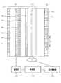
図4に示すように、本発明による立体映像表示装置は、映像を形成するディスプレイパネル100、ディスプレイパネル100から出力された映像ビームの偏光方向を印加された電圧によって変換する偏光変換素子110及び偏光変換素子110を通過したビームを偏光方向によって通過または遮断するためのパターンに形成されたスイッチングバリアユニット120を備える。 As shown in FIG. 4, a stereoscopic image display apparatus according to the present invention includes a
ディスプレイパネル100は、偏光依存型のLCDまたはFLCDであることが望ましく、透過型または反射型でありえる。ディスプレイパネル100は、具体的に、第1偏光板101、第1ガラス板102、TFT(薄膜トランジスタ)駆動部103により駆動されるTFT 104、第2ガラス板105及び第2偏光板106を備えて構成される。 The
偏光変換素子110は、多様な方法で具現可能であるが、例えば液晶に印加する電圧によってその偏光方向が変換される液晶偏光変換器で構成されうる。例えば、偏光変換素子110に電圧駆動源114から第1電圧V1が入力されるとき、入射ビームの偏光方向がそのまま維持されて通過され、第2電圧V2が入力されるとき、入射ビームの偏光方向が90°変換し、第3電圧V3が入力されるとき、入射ビームの偏光方向が45°変換する。偏光変換素子110には、同期部112によりディスプレイパネル100での映像出力と同期されて電圧が印加される。 The
スイッチングバリアユニット120は、第1偏光方向を有する第1偏光部120aと第2偏光方向を有する第2偏光部120bとが交互に配列されたパターンに構成されうる。前記第1偏光方向及び第2偏光方向は、互いに直交する直線偏光であることが望ましく、例えば第1偏光方向は、ディスプレイパネル100から出射されるビームの偏光方向と同じであり、第2偏光方向は、ディスプレイパネル100から出射されるビームの偏光方向に直交する方向を有する。ディスプレイパネル100で形成された映像ビームがスイッチングバリアユニット120を通過するとき、第1偏光部120aを通じて通過され、第2偏光部120bにより遮断されるか、または第1偏光部120aにより遮断され、第2偏光部120bを通じて通過することによって、解像度の低下なしに3次元映像を具現できる。 The
隣り合う第1偏光部120aの間または隣り合う第2偏光部120bの間の間隔ピッチpは、次の式により決定される。 The spacing pitch p between adjacent first polarizing
ここで、m=e/iであり、eは、左眼と右眼との平均距離であって、例えば65mmであり、iは、ディスプレイパネルのピクセルピッチを表す。式(1)によるピッチpは、既存の固定式バリア方式の立体映像表示装置でのバリア間のピッチと同一に適用される。そして、式は、一般的な2時点のバリア構造に適用される。
Here, m = e / i, e is an average distance between the left eye and the right eye, for example, 65 mm, and i represents a pixel pitch of the display panel. The pitch p according to the equation (1) is applied in the same manner as the pitch between the barriers in the existing fixed-barrier stereoscopic image display device. The formula is then applied to a general two-point barrier structure.
第1実施形態による3次元映像ディスプレイ装置で3次元映像が表示される作用について説明すると、次の通りである。 The operation of displaying a 3D image on the 3D image display apparatus according to the first embodiment will be described as follows.
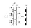
図5Aに示すように、ディスプレイパネル100に入力される一つのフレームの映像信号は、第1フィールド映像信号と第2フィールド映像信号とで構成され、第1フィールド映像信号と第2フィールド映像信号とが時間順次にディスプレイパネル100に入力される。ディスプレイパネル100から出力される第1フィールド映像ビームが第1偏光方向を有するとき、例えばS偏光ビームであるとき、偏光方向変換素子110に、前記第1フィールド映像に同期されてV1の電圧が印加されれば、前記第1フィールド映像ビームは、偏光方向が変わらず、偏光方向変換素子110を通過してスイッチングバリアユニット120に入射される。第1偏光ビームは、スイッチングバリアユニット120の第1偏光部120aを通じて通過する一方、第2偏光部120bにより遮断されて、結果的にスイッチングバリアユニットが120’で表示された等価化されたバリアのように作用する。 As shown in FIG. 5A, the video signal of one frame input to the
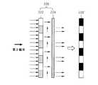
次いで、図5Bに示すように、ディスプレイパネル100から第2フィールド映像ビームが出力されるとき、偏光方向変換素子110に、前記第2フィールド映像に同期されてV2の電圧が印加されれば、前記第2フィールド映像ビームは、偏光方向が第2偏光方向、例えばP偏光ビームに変換されて、スイッチングバリアユニット120に入射される。第2偏光ビームは、スイッチングバリアユニット120の第1偏光部120aにより遮断され、第2偏光部120bを通じて通過して、結果的に120”で表示された等価化されたバリアのように作用する。このように、スイッチングバリアユニット120は、入射ビームの偏光方向によってビームを通過させる開口部とビームを遮断させる非開口部とが時間順次に反転されつつスイッチングされることによって、3次元映像を解像度の低下なしに具現可能にする。 5B, when the second field image beam is output from the
図6は、第1フィールド映像がスイッチングバリアユニット120の第1偏光部120aを通過して左眼映像と右眼映像とに分離され、第2フィールド映像がスイッチングバリアユニット120の第2偏光部120bを通過して左眼映像と右眼映像とに分離されることを図表化した図であって、3次元映像が解像度の低下なしに具現されることを示す。 FIG. 6 illustrates that the first field image passes through the
図7Aは、偏光変換素子110で偏光方向の変化なしに通過された第1偏光方向を有する第1フィールド映像が、等価化されたスイッチングバリアユニット120’を通じて左眼映像と右眼映像とに分離される場合を示す図であって、第1フィールド映像に対しては、左眼に偶数列の左眼映像Lf1、右眼に奇数列の右眼映像Rf1が結ばれる。ここで、実線は、スイッチングバリアユニットの開口部を通じて通過するビームを、点線は、スイッチングバリアユニットの非開口部を通じて遮断されるビームを表したものであり、左眼映像と右眼映像とを区別して示した。FIG. 7A shows that the first field image having the first polarization direction passed through the
図7Bは、偏光変換素子110で偏光方向が第2偏光方向に変換されて等価化されたスイッチングバリアユニット120"を通じて点線で表示された第2フィールド左眼映像Lf2と第2フィールド右眼映像Rf2とに分離されて、それぞれ左眼と右眼とに結ばれる場合を示す図である。第2フィールド映像に対しては、左眼に奇数列の左眼映像Lf2、右眼に偶数列の右眼映像Rf2が結ばれる。FIG. 7B shows the second field left-eye image Lf2 and the second field right-eye image displayed by dotted lines through the
これと異なり、第1フィールド映像に対しては、左眼に奇数列の左眼映像、右眼に偶数列の右眼映像を結び、第2フィールド映像に対しては、左眼に偶数列の左眼映像、右眼に奇数列の右眼映像を結ぶことも可能である。 In contrast to this, for the first field image, the left eye is connected to the left eye of the odd numbered column, the right eye is connected to the right eye of the even numbered column, and the second field image is connected to the left eye of the even numbered column. It is also possible to connect an odd-numbered right eye image to the left eye image and the right eye.
第1フィールド映像及び第2フィールド映像は、人の目が感知できない速い速度で順次に出力されて、2次元映像に比べて解像度の低下なしに3次元映像を見ることができる。一般的に、第1フィールド映像と第2フィールド映像との周期が1/120秒以下であるとき、人の目が明滅を感知できないと知られており、この程度の動作速度は、FLCやOCB(Optical Compensated Bend)などの特殊な液晶を利用して具現可能である。 The first field image and the second field image are sequentially output at a high speed that human eyes cannot perceive, and a three-dimensional image can be viewed without a decrease in resolution as compared with the two-dimensional image. In general, it is known that when the period between the first field image and the second field image is 1/120 seconds or less, the human eye cannot perceive blinking. It can be implemented using a special liquid crystal such as (Optical Compensated Bend).
一方、本発明による立体映像ディスプレイ装置では、3次元映像と共に2次元映像が表示される。その作用効果について説明すれば、ディスプレイパネル100から出力された第1偏光ビームが偏光変換素子110に入射され、偏光変換素子110にV3電圧が印加されれば、ビームの偏光方向が45°に変換されてスイッチングバリアユニット120に入射される。図8は、45°の偏光方向を有するビームがスイッチングバリアユニット120に入射される場合を示す図であって、45°の偏光方向を有するビームは、第1偏光部120a及び第2偏光部120bの両側を通過する。このとき、入射ビームの一部は通過されずに損失されるが、第1及び第2偏光部120a,120bの両側を通じて通過されるので、等価化されたスイッチングバリアユニット120’’’の全体を通じて出力される。したがって、ディスプレイパネルにより形成された映像が左眼映像と右眼映像とに分離されずに、2次元映像を形成する。 Meanwhile, in the stereoscopic image display apparatus according to the present invention, a 2D image is displayed together with a 3D image. Describing the function and effect, if the first polarized beam output from the
前述したように、ディスプレイパネル100から出力される第1フィールド映像及び第2フィールド映像に同期されて時間順次に印加される第1電圧V1及び第2電圧V2によって駆動される偏光変換素子110を通じて、入射ビームの偏光方向が変換されてスイッチングバリアユニット120に入射されることによって、3次元映像が2次元映像に比べて解像度の低下なしに具現されうる。スイッチングバリアユニット120は、入射ビームの偏光方向によってバリア部がスイッチングされる作用を行う。 As described above, through the
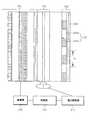
図9に示すように、本発明の第2実施形態による立体映像ディスプレイ装置は、映像を形成するディスプレイパネル200、前記映像ビームの偏光方向を変換する偏光変換素子210、及び偏光変換素子210を通過したビームの偏光方向によってビームを通過または遮断するパターンを有するスイッチングバリアユニット220を備える。 As shown in FIG. 9, the stereoscopic image display apparatus according to the second embodiment of the present invention passes through the
ディスプレイパネル200は、駆動部208により空間変調されて映像を形成するものであって、例えばLCDまたはFLCDで構成されうる。偏光変換素子210は、同期部212を通じて駆動部208に同期されて電圧駆動源214から印加される電圧によって、入射ビームの偏光方向を変換する。ディスプレイパネル200及び偏光変換素子210についての具体的な構造及び作用効果は、第1実施形態でのディスプレイパネル100及び偏光変換素子110と実質的に同一であるので、ここではその詳細な説明を省略する。 The
スイッチングバリアユニット220は、位相遅延部222aと透過部222bとが交互に反復されて配列された部分位相遅延板222及び偏光板224を備える。隣り合う位相遅延部222aの間の間隔ピッチ及び隣り合う透過部の間の間隔ピッチpは、式(1)によって設計される。位相遅延部222aは、1/2波長板であって、偏光変換素子210を通過したビームの偏光方向を90°遅延させることによって、S偏光ビームをP偏光ビームに、またはP偏光ビームをS偏光ビームに変換する。これと共に透過部222bを通過するビームは、偏光方向の変化なしに透過される。結果的に、部分位相遅延板222を通過したビームは、第1偏光ビームと第2偏光ビームとが混合されて存在し、偏光板224の偏光方向によって、第1偏光ビーム及び第2偏光ビームのうちいずれか一つのビームが偏光板224を通過する。 The switching
図10A及び図10Bは、スイッチングバリアユニット220のスイッチング作用を説明するための図である。偏光変換素子210を通じて第1偏光ビームが部分位相遅延板222に入射されれば、位相遅延部222aを通じて第1偏光ビームが第2偏光ビームに変換され、透過部222bを通じては第1偏光ビームがそのまま通過される。次いで、偏光変換素子210を通じて第2偏光ビームが部分位相遅延板222に入射されれば、位相遅延部222aを通じて第2偏光ビームが第1偏光ビームに変換され、透過部222bを通じては第2偏光ビームがそのまま通過される。第1偏光ビームが入射されたとき及び第2偏光ビームが入射されたときを比較すれば、第1偏光ビームと第2偏光ビームとの位置が互いに逆転され、結果的に偏光板224の偏光方向によって通過する偏光ビームの位置が相異なる。例えば、偏光板224が第1偏光方向を有するとき、第1偏光ビームのみが通過され、第2偏光ビームは遮断され、通過される第1偏光ビームの位置が時間順次にスイッチングされることによって、スイッチングバリアの機能を行う。かかる作用は、等価化されたスイッチングバリアユニット220’,220”を通じて容易に分かる。 10A and 10B are diagrams for explaining the switching action of the
図11は、第2実施形態による立体映像表示装置で2次元映像が具現されるとき、スイッチングバリアユニット220の作用を説明するための図である。 FIG. 11 is a diagram for explaining the operation of the
ディスプレイパネル200で2次元映像が形成されるとき、偏光変換素子210で第3電圧V3が印加され、偏光変換素子210により映像ビームの偏光方向が45°に変換されてスイッチングバリアユニット220に入射される。45°の偏光方向を有するビームが位相遅延部222a及び透過部222bの両側を通じて通過された後、偏光板224を通じて通過される。結果的に、等価化されたスイッチングバリアユニット220’’’のようにスイッチングバリアユニット220の全体を通じて映像が通過されるので、左眼映像と右眼映像とに分離されず、2次元映像が具現される。 When a 2D image is formed on the
本発明では、必要に応じて、2次元モード及び3次元モードを選択的に具現でき、3次元映像を2次元映像に比べて解像度の低下なしに具現できる。 In the present invention, the two-dimensional mode and the three-dimensional mode can be selectively implemented as necessary, and a three-dimensional image can be implemented without a decrease in resolution as compared with the two-dimensional image.
前記した実施形態は、例示的なものに過ぎず、当業者ならば、これから多様な変形及び均等な他の実施形態が可能である。したがって、本発明の真の技術的保護範囲は、特許請求の範囲に記載された発明の技術的思想により決まらねばならない。 The above-described embodiments are merely illustrative, and various modifications and other equivalent embodiments can be made by those skilled in the art. Therefore, the true technical protection scope of the present invention must be determined by the technical idea of the invention described in the claims.
本発明は、立体映像表示装置関連の技術分野に適用可能である。 The present invention is applicable to technical fields related to stereoscopic video display devices.
100 ディスプレイパネル
101 第1偏光板
102 第1ガラス板
103 TFT駆動部
104 TFT
105 第2ガラス板
106 第2偏光板
110 偏光変換素子
112 同期部
114 電圧駆動源
120 スイッチングバリアユニット
120a 第1偏光部
120b 第2偏光部100
105
Claims (7)
Translated fromJapanese前記映像信号に同期して印加される電圧によって、入射ビームの偏光方向を変換させる偏光変換素子と、
前記偏光変換素子から出力されたビームの位相を遅延させる1/2波長板である位相遅延部と偏光変換素子から出力されたビームを通過させる透過部とが交互に配列された部分位相遅延板、及び前記部分位相遅延板の次に配置された偏光板を備えたスイッチングバリアユニットとを備え、
前記偏光変換素子によって前記入射ビームの偏光方向が維持される状態と90°変換される状態とになるよう時間順次にスイッチングされることにより3次元映像が表示され、前記偏光変換素子によって該偏光方向が45°変換される状態になったとき2次元映像が表示され、
隣り合う前記位相遅延部の間または隣り合う前記透過部の間の間隔ピッチpは、次の条件式:
A polarization conversion element that converts a polarization direction of an incident beam by a voltage applied in synchronization with the video signal;
A partial phase delayplate in which a phase delay unitthat is ahalf-wave plate that delaysthe phase of the beam output from the polarization conversion element and a transmission unit that passes the beam output from the polarization conversion element are alternately arranged; And a switching barrier unit including a polarizing plate disposed next to the partial phase retardation plate,
Whereinsaid incident beam three-dimensional imageby the polarization directionsare time sequentially switching so as to be a state that isa state and 90 °convertingmaintainedin the polarization conversion element is displayed,the polarization direction by the polarization converter 2D image is displayed whenis converted to 45 ° ,
An interval pitch p between the adjacent phase delay portions or between the adjacent transmission portions is expressed by the following conditional expression:
Applications Claiming Priority (2)
| Application Number | Priority Date | Filing Date | Title |
|---|---|---|---|
| KR1020050055416AKR20060135450A (en) | 2005-06-25 | 2005-06-25 | 2-D combined stereoscopic display |
| KR10-2005-0055416 | 2005-06-25 |
Publications (2)
| Publication Number | Publication Date |
|---|---|
| JP2007004179A JP2007004179A (en) | 2007-01-11 |
| JP5426067B2true JP5426067B2 (en) | 2014-02-26 |
Family
ID=37009148
Family Applications (1)
| Application Number | Title | Priority Date | Filing Date |
|---|---|---|---|
| JP2006173781AExpired - Fee RelatedJP5426067B2 (en) | 2005-06-25 | 2006-06-23 | Two-dimensional stereoscopic display device |
Country Status (5)
| Country | Link |
|---|---|
| US (1) | US7728789B2 (en) |
| EP (1) | EP1737250A3 (en) |
| JP (1) | JP5426067B2 (en) |
| KR (1) | KR20060135450A (en) |
| CN (1) | CN100429560C (en) |
Families Citing this family (48)
| Publication number | Priority date | Publication date | Assignee | Title |
|---|---|---|---|---|
| KR100728113B1 (en)* | 2005-10-20 | 2007-06-13 | 삼성에스디아이 주식회사 | Stereoscopic Display and Driving Method |
| KR101299728B1 (en)* | 2007-01-24 | 2013-08-22 | 삼성전자주식회사 | High efficient 2D-3D switchable display apparatus |
| KR100846707B1 (en)* | 2007-02-27 | 2008-07-16 | 삼성에스디아이 주식회사 | Electronic imaging equipment |
| US20120268451A1 (en)* | 2007-06-25 | 2012-10-25 | Industrial Technology Research Institute | Three-dimensional (3d) display |
| KR20090018528A (en)* | 2007-08-17 | 2009-02-20 | 삼성전자주식회사 | 2D / 3D image compatible display device and its driving method |
| KR100908724B1 (en)* | 2007-10-22 | 2009-07-22 | 삼성모바일디스플레이주식회사 | Barrier device and electronic imaging device including the same |
| KR101291799B1 (en)* | 2009-05-29 | 2013-07-31 | 엘지디스플레이 주식회사 | Stereoscopic Image Display Device |
| KR101094283B1 (en) | 2009-08-21 | 2011-12-19 | 삼성모바일디스플레이주식회사 | Three dimensional image display device |
| JP2011107589A (en)* | 2009-11-20 | 2011-06-02 | Sony Corp | Stereoscopic display apparatus |
| JP5353770B2 (en)* | 2010-03-05 | 2013-11-27 | カシオ計算機株式会社 | Stereoscopic image observation apparatus, stereoscopic video display apparatus, and program |
| CN102193204B (en)* | 2010-03-11 | 2016-08-31 | 京东方科技集团股份有限公司 | Three-dimensional display and three-dimensional display system |
| CN101799599A (en)* | 2010-03-18 | 2010-08-11 | 友达光电股份有限公司 | Stereoscopic display and display method thereof |
| CN102253495B (en)* | 2010-05-18 | 2013-10-30 | 京东方科技集团股份有限公司 | Dual-view display equipment and system |
| CN101852922A (en)* | 2010-05-24 | 2010-10-06 | 友达光电股份有限公司 | Display device capable of switching two-dimensional and three-dimensional display modes |
| US8615622B2 (en) | 2010-06-23 | 2013-12-24 | International Business Machines Corporation | Non-standard I/O adapters in a standardized I/O architecture |
| US8683108B2 (en) | 2010-06-23 | 2014-03-25 | International Business Machines Corporation | Connected input/output hub management |
| US8677180B2 (en) | 2010-06-23 | 2014-03-18 | International Business Machines Corporation | Switch failover control in a multiprocessor computer system |
| US8918573B2 (en) | 2010-06-23 | 2014-12-23 | International Business Machines Corporation | Input/output (I/O) expansion response processing in a peripheral component interconnect express (PCIe) environment |
| US8645606B2 (en) | 2010-06-23 | 2014-02-04 | International Business Machines Corporation | Upbound input/output expansion request and response processing in a PCIe architecture |
| US8656228B2 (en) | 2010-06-23 | 2014-02-18 | International Business Machines Corporation | Memory error isolation and recovery in a multiprocessor computer system |
| US8745292B2 (en) | 2010-06-23 | 2014-06-03 | International Business Machines Corporation | System and method for routing I/O expansion requests and responses in a PCIE architecture |
| US8645767B2 (en) | 2010-06-23 | 2014-02-04 | International Business Machines Corporation | Scalable I/O adapter function level error detection, isolation, and reporting |
| KR101279660B1 (en)* | 2010-07-07 | 2013-06-27 | 엘지디스플레이 주식회사 | 3d image display device and driving method thereof |
| TWI413404B (en)* | 2010-07-19 | 2013-10-21 | Chicony Electronics Co Ltd | 3d image processing system and camera and 3d image generating device applying to 3d image processing system |
| JP5621500B2 (en)* | 2010-10-19 | 2014-11-12 | ソニー株式会社 | Stereoscopic display device and stereoscopic display method |
| DE102010043858A1 (en)* | 2010-11-12 | 2012-05-16 | BSH Bosch und Siemens Hausgeräte GmbH | Hot beverage preparation device with data transmission device |
| KR101709160B1 (en)* | 2010-12-20 | 2017-02-22 | 엘지디스플레이 주식회사 | Device for displaying 2D/3D display-convertible image |
| GB2486806B (en) | 2010-12-20 | 2014-12-10 | Lg Display Co Ltd | Image display device |
| KR101763941B1 (en)* | 2010-12-20 | 2017-08-01 | 엘지디스플레이 주식회사 | Stereoscpic image display device |
| JP5781322B2 (en)* | 2011-02-15 | 2015-09-16 | 株式会社三共 | Game machine |
| CN102141714B (en)* | 2011-03-31 | 2013-10-23 | 昆山龙腾光电有限公司 | Display device |
| JP5662290B2 (en) | 2011-09-29 | 2015-01-28 | 株式会社ジャパンディスプレイ | Display device |
| US9104048B2 (en) | 2012-01-25 | 2015-08-11 | International Business Machines Corporation | Three dimensional image projector with single modulator |
| US20130188149A1 (en) | 2012-01-25 | 2013-07-25 | International Business Machines Corporation | Three dimensional image projector |
| US8992024B2 (en) | 2012-01-25 | 2015-03-31 | International Business Machines Corporation | Three dimensional image projector with circular light polarization |
| US8960913B2 (en) | 2012-01-25 | 2015-02-24 | International Busniess Machines Corporation | Three dimensional image projector with two color imaging |
| US9004700B2 (en) | 2012-01-25 | 2015-04-14 | International Business Machines Corporation | Three dimensional image projector stabilization circuit |
| US9325977B2 (en) | 2012-01-25 | 2016-04-26 | International Business Machines Corporation | Three dimensional LCD monitor display |
| US8985785B2 (en) | 2012-01-25 | 2015-03-24 | International Business Machines Corporation | Three dimensional laser image projector |
| DE102012003789A1 (en)* | 2012-02-25 | 2013-08-29 | 3 D Graphics Gmbh | Monitor for stereoscopic 3D image display and associated operating method for a perceptual coding |
| CN102722074B (en)* | 2012-03-02 | 2015-07-29 | 深圳市光峰光电技术有限公司 | Polarized light light-emitting device, light-emitting device and projector |
| US9667948B2 (en) | 2013-10-28 | 2017-05-30 | Ray Wang | Method and system for providing three-dimensional (3D) display of two-dimensional (2D) information |
| CN103676178B (en)* | 2013-12-19 | 2018-05-29 | 深圳市华星光电技术有限公司 | A kind of display |
| CN104330952A (en)* | 2014-11-10 | 2015-02-04 | 电子科技大学 | 2D/3D switchable display device |
| EP3029380A1 (en)* | 2014-12-03 | 2016-06-08 | Electrolux Appliances Aktiebolag | Method for performing a treatment by a domestic appliance and for processing information of said treatment by a mobile computer device |
| JP2015084110A (en)* | 2014-12-04 | 2015-04-30 | 株式会社ジャパンディスプレイ | Display device |
| CN107728363B (en)* | 2017-10-26 | 2020-08-11 | 宁波视睿迪光电有限公司 | Stereoscopic display device and control method thereof |
| CN107884957B (en)* | 2017-12-28 | 2021-03-02 | Tcl华星光电技术有限公司 | Display panel and display device |
Family Cites Families (26)
| Publication number | Priority date | Publication date | Assignee | Title |
|---|---|---|---|---|
| US2631496A (en)* | 1947-08-08 | 1953-03-17 | Miles P Rehorn | Stereoscopic viewing method and apparatus |
| US4343535A (en)* | 1979-12-14 | 1982-08-10 | Hughes Aircraft Company | Liquid crystal light valve |
| JP2857429B2 (en)* | 1989-10-02 | 1999-02-17 | 日本放送協会 | Three-dimensional image display apparatus and method |
| US5416510A (en)* | 1991-08-28 | 1995-05-16 | Stereographics Corporation | Camera controller for stereoscopic video system |
| JPH05122733A (en)* | 1991-10-28 | 1993-05-18 | Nippon Hoso Kyokai <Nhk> | 3D image display device |
| JP3297191B2 (en)* | 1994-03-30 | 2002-07-02 | 三菱電機株式会社 | Projection display device |
| SE502868C2 (en)* | 1994-04-26 | 1996-02-05 | Hoernell Elektrooptik Ab | Welding quick filter with improved angular properties |
| JPH0915532A (en)* | 1995-06-29 | 1997-01-17 | Canon Inc | Stereoscopic image display method and stereoscopic image display device using the same |
| JPH09251147A (en)* | 1996-03-15 | 1997-09-22 | Nec Corp | Optical wavelength band-pass filter control system |
| US6046849A (en)* | 1996-09-12 | 2000-04-04 | Sharp Kabushiki Kaisha | Parallax barrier, display, passive polarisation modulating optical element and method of making such an element |
| US6055103A (en)* | 1997-06-28 | 2000-04-25 | Sharp Kabushiki Kaisha | Passive polarisation modulating optical element and method of making such an element |
| KR100261582B1 (en)* | 1997-11-06 | 2000-07-15 | 윤종용 | 3-dimensional image projection display device |
| JPH11234703A (en)* | 1998-02-09 | 1999-08-27 | Toshiba Corp | 3D display device |
| US6710920B1 (en)* | 1998-03-27 | 2004-03-23 | Sanyo Electric Co., Ltd | Stereoscopic display |
| JP4185264B2 (en)* | 2001-07-02 | 2008-11-26 | 富士フイルム株式会社 | Polarization direction control element and exposure apparatus |
| US6697550B2 (en)* | 2001-10-24 | 2004-02-24 | Renka Corporation | Fast 1×N fiber-optic switch |
| JP2003202519A (en)* | 2001-12-28 | 2003-07-18 | Canon Inc | 3D image display device |
| JP2003202517A (en)* | 2001-12-28 | 2003-07-18 | Canon Inc | 3D image display device |
| JP2003337390A (en)* | 2002-05-17 | 2003-11-28 | Canon Inc | Image display device and image display system |
| JP2004241962A (en)* | 2003-02-05 | 2004-08-26 | Pioneer Electronic Corp | Display device and method therefor |
| KR100540109B1 (en) | 2003-02-06 | 2006-01-10 | 가부시끼가이샤 도시바 | Stereoscopic image display apparatus |
| JP2004287857A (en)* | 2003-03-20 | 2004-10-14 | Sanyo Electric Co Ltd | Program, recording medium, server device and image filter |
| JP2005077437A (en)* | 2003-08-29 | 2005-03-24 | Olympus Corp | Video display device, stereoscopic video display device, and on-vehicle video display device |
| US7413512B2 (en)* | 2003-09-15 | 2008-08-19 | Igt | Display panel for a gaming apparatus |
| JP2005215475A (en)* | 2004-01-30 | 2005-08-11 | Seiko Epson Corp | projector |
| KR20040077596A (en) | 2004-07-28 | 2004-09-04 | 손귀연 | Stereoscopic Image Display Device Based on Flat Panel Display |
- 2005
- 2005-06-25KRKR1020050055416Apatent/KR20060135450A/ennot_activeCeased
- 2006
- 2006-04-03USUS11/395,306patent/US7728789B2/ennot_activeExpired - Fee Related
- 2006-06-02EPEP06252873Apatent/EP1737250A3/ennot_activeCeased
- 2006-06-19CNCNB2006100930561Apatent/CN100429560C/ennot_activeExpired - Fee Related
- 2006-06-23JPJP2006173781Apatent/JP5426067B2/ennot_activeExpired - Fee Related
Also Published As
| Publication number | Publication date |
|---|---|
| EP1737250A3 (en) | 2007-03-14 |
| CN1885096A (en) | 2006-12-27 |
| CN100429560C (en) | 2008-10-29 |
| JP2007004179A (en) | 2007-01-11 |
| EP1737250A2 (en) | 2006-12-27 |
| KR20060135450A (en) | 2006-12-29 |
| US20060290888A1 (en) | 2006-12-28 |
| US7728789B2 (en) | 2010-06-01 |
Similar Documents
| Publication | Publication Date | Title |
|---|---|---|
| JP5426067B2 (en) | Two-dimensional stereoscopic display device | |
| JP4644594B2 (en) | 3D image display device | |
| CN100520493C (en) | High resolution autostereoscopic display | |
| US7646537B2 (en) | High-resolution field sequential autostereoscopic display | |
| JP4925702B2 (en) | Stereoscopic video display device for 2D / 3D video compatibility using a polarizing grating screen | |
| US7626644B2 (en) | Multiview autostereoscopic display | |
| KR101128519B1 (en) | High resolution autostereoscopic display | |
| US8274556B2 (en) | Backlight unit and 2D/3D switchable image display device employing the backlight unit | |
| JP4979951B2 (en) | Direct view stereoscopic image display with moiré pattern removed | |
| KR101086411B1 (en) | Stereoscopic image display device for 2D / 3D image compatibility | |
| JP2002250895A (en) | Stereoscopic image display method and stereoscopic image display device using the same | |
| US20090046214A1 (en) | 2d/3d convertible display apparatus and method of driving the same | |
| KR20040103724A (en) | Display device capable of displaying 2-dimensional and 3-dimensional images | |
| KR20080069869A (en) | High efficiency display device for 2D / 3D image compatibility | |
| JP2011002832A (en) | Image display device and method | |
| JP4495982B2 (en) | Stereoscopic image display device and light deflection element | |
| JP2009031524A (en) | Stereoscopic image display device and stereoscopic image display method | |
| JP2004271617A (en) | Stereoscopic video display device | |
| JP2002296540A (en) | Stereoscopic image display device without spectacles | |
| JP2006047507A (en) | Display device and display method | |
| JP2005520216A (en) | 3D stereoscopic display | |
| KR20040026032A (en) | 3-dimension display system | |
| TWI386035B (en) | Three-dimensional display device and three-dimensional display method | |
| JP2008245068A (en) | Stereoscopic image pickup and display system, and stereoscopic image display device | |
| JP2007304236A (en) | Liquid crystal display |
Legal Events
| Date | Code | Title | Description |
|---|---|---|---|
| A621 | Written request for application examination | Free format text:JAPANESE INTERMEDIATE CODE: A621 Effective date:20090604 | |
| A977 | Report on retrieval | Free format text:JAPANESE INTERMEDIATE CODE: A971007 Effective date:20110712 | |
| A131 | Notification of reasons for refusal | Free format text:JAPANESE INTERMEDIATE CODE: A131 Effective date:20110726 | |
| A521 | Request for written amendment filed | Free format text:JAPANESE INTERMEDIATE CODE: A523 Effective date:20111026 | |
| A02 | Decision of refusal | Free format text:JAPANESE INTERMEDIATE CODE: A02 Effective date:20120612 | |
| A521 | Request for written amendment filed | Free format text:JAPANESE INTERMEDIATE CODE: A523 Effective date:20121012 | |
| A911 | Transfer to examiner for re-examination before appeal (zenchi) | Free format text:JAPANESE INTERMEDIATE CODE: A911 Effective date:20121019 | |
| A912 | Re-examination (zenchi) completed and case transferred to appeal board | Free format text:JAPANESE INTERMEDIATE CODE: A912 Effective date:20121207 | |
| A521 | Request for written amendment filed | Free format text:JAPANESE INTERMEDIATE CODE: A523 Effective date:20130925 | |
| A61 | First payment of annual fees (during grant procedure) | Free format text:JAPANESE INTERMEDIATE CODE: A61 Effective date:20131128 | |
| R150 | Certificate of patent or registration of utility model | Free format text:JAPANESE INTERMEDIATE CODE: R150 Ref document number:5426067 Country of ref document:JP Free format text:JAPANESE INTERMEDIATE CODE: R150 | |
| R250 | Receipt of annual fees | Free format text:JAPANESE INTERMEDIATE CODE: R250 | |
| R250 | Receipt of annual fees | Free format text:JAPANESE INTERMEDIATE CODE: R250 | |
| LAPS | Cancellation because of no payment of annual fees |