JP5425268B2 - Integrated circuit - Google Patents
Integrated circuitDownload PDFInfo
- Publication number
- JP5425268B2 JP5425268B2JP2012144170AJP2012144170AJP5425268B2JP 5425268 B2JP5425268 B2JP 5425268B2JP 2012144170 AJP2012144170 AJP 2012144170AJP 2012144170 AJP2012144170 AJP 2012144170AJP 5425268 B2JP5425268 B2JP 5425268B2
- Authority
- JP
- Japan
- Prior art keywords
- dch
- resource blocks
- distributed virtual
- virtual resource
- numbers
- Prior art date
- Legal status (The legal status is an assumption and is not a legal conclusion. Google has not performed a legal analysis and makes no representation as to the accuracy of the status listed.)
- Active
Links
Images


Classifications
- H—ELECTRICITY
- H04—ELECTRIC COMMUNICATION TECHNIQUE
- H04W—WIRELESS COMMUNICATION NETWORKS
- H04W72/00—Local resource management
- H04W72/20—Control channels or signalling for resource management
- H04W72/23—Control channels or signalling for resource management in the downlink direction of a wireless link, i.e. towards a terminal
- H—ELECTRICITY
- H04—ELECTRIC COMMUNICATION TECHNIQUE
- H04W—WIRELESS COMMUNICATION NETWORKS
- H04W72/00—Local resource management
- H04W72/04—Wireless resource allocation
- H04W72/044—Wireless resource allocation based on the type of the allocated resource
- H04W72/0446—Resources in time domain, e.g. slots or frames
- H—ELECTRICITY
- H04—ELECTRIC COMMUNICATION TECHNIQUE
- H04L—TRANSMISSION OF DIGITAL INFORMATION, e.g. TELEGRAPHIC COMMUNICATION
- H04L5/00—Arrangements affording multiple use of the transmission path
- H04L5/003—Arrangements for allocating sub-channels of the transmission path
- H04L5/0037—Inter-user or inter-terminal allocation
- H—ELECTRICITY
- H04—ELECTRIC COMMUNICATION TECHNIQUE
- H04B—TRANSMISSION
- H04B7/00—Radio transmission systems, i.e. using radiation field
- H04B7/02—Diversity systems; Multi-antenna system, i.e. transmission or reception using multiple antennas
- H04B7/12—Frequency diversity
- H—ELECTRICITY
- H04—ELECTRIC COMMUNICATION TECHNIQUE
- H04L—TRANSMISSION OF DIGITAL INFORMATION, e.g. TELEGRAPHIC COMMUNICATION
- H04L1/00—Arrangements for detecting or preventing errors in the information received
- H04L1/0001—Systems modifying transmission characteristics according to link quality, e.g. power backoff
- H04L1/0002—Systems modifying transmission characteristics according to link quality, e.g. power backoff by adapting the transmission rate
- H04L1/0003—Systems modifying transmission characteristics according to link quality, e.g. power backoff by adapting the transmission rate by switching between different modulation schemes
- H—ELECTRICITY
- H04—ELECTRIC COMMUNICATION TECHNIQUE
- H04L—TRANSMISSION OF DIGITAL INFORMATION, e.g. TELEGRAPHIC COMMUNICATION
- H04L1/00—Arrangements for detecting or preventing errors in the information received
- H04L1/0001—Systems modifying transmission characteristics according to link quality, e.g. power backoff
- H04L1/0009—Systems modifying transmission characteristics according to link quality, e.g. power backoff by adapting the channel coding
- H—ELECTRICITY
- H04—ELECTRIC COMMUNICATION TECHNIQUE
- H04L—TRANSMISSION OF DIGITAL INFORMATION, e.g. TELEGRAPHIC COMMUNICATION
- H04L1/00—Arrangements for detecting or preventing errors in the information received
- H04L1/004—Arrangements for detecting or preventing errors in the information received by using forward error control
- H04L1/0056—Systems characterized by the type of code used
- H04L1/0071—Use of interleaving
- H—ELECTRICITY
- H04—ELECTRIC COMMUNICATION TECHNIQUE
- H04L—TRANSMISSION OF DIGITAL INFORMATION, e.g. TELEGRAPHIC COMMUNICATION
- H04L5/00—Arrangements affording multiple use of the transmission path
- H04L5/0001—Arrangements for dividing the transmission path
- H04L5/0003—Two-dimensional division
- H04L5/0005—Time-frequency
- H04L5/0007—Time-frequency the frequencies being orthogonal, e.g. OFDM(A) or DMT
- H—ELECTRICITY
- H04—ELECTRIC COMMUNICATION TECHNIQUE
- H04L—TRANSMISSION OF DIGITAL INFORMATION, e.g. TELEGRAPHIC COMMUNICATION
- H04L5/00—Arrangements affording multiple use of the transmission path
- H04L5/0001—Arrangements for dividing the transmission path
- H04L5/0028—Variable division
- H—ELECTRICITY
- H04—ELECTRIC COMMUNICATION TECHNIQUE
- H04L—TRANSMISSION OF DIGITAL INFORMATION, e.g. TELEGRAPHIC COMMUNICATION
- H04L5/00—Arrangements affording multiple use of the transmission path
- H04L5/003—Arrangements for allocating sub-channels of the transmission path
- H04L5/0037—Inter-user or inter-terminal allocation
- H04L5/0039—Frequency-contiguous, i.e. with no allocation of frequencies for one user or terminal between the frequencies allocated to another
- H—ELECTRICITY
- H04—ELECTRIC COMMUNICATION TECHNIQUE
- H04L—TRANSMISSION OF DIGITAL INFORMATION, e.g. TELEGRAPHIC COMMUNICATION
- H04L5/00—Arrangements affording multiple use of the transmission path
- H04L5/003—Arrangements for allocating sub-channels of the transmission path
- H04L5/0037—Inter-user or inter-terminal allocation
- H04L5/0041—Frequency-non-contiguous
- H—ELECTRICITY
- H04—ELECTRIC COMMUNICATION TECHNIQUE
- H04L—TRANSMISSION OF DIGITAL INFORMATION, e.g. TELEGRAPHIC COMMUNICATION
- H04L5/00—Arrangements affording multiple use of the transmission path
- H04L5/003—Arrangements for allocating sub-channels of the transmission path
- H04L5/0058—Allocation criteria
- H04L5/006—Quality of the received signal, e.g. BER, SNR, water filling
- H—ELECTRICITY
- H04—ELECTRIC COMMUNICATION TECHNIQUE
- H04L—TRANSMISSION OF DIGITAL INFORMATION, e.g. TELEGRAPHIC COMMUNICATION
- H04L5/00—Arrangements affording multiple use of the transmission path
- H04L5/003—Arrangements for allocating sub-channels of the transmission path
- H04L5/0058—Allocation criteria
- H04L5/0064—Rate requirement of the data, e.g. scalable bandwidth, data priority
- H—ELECTRICITY
- H04—ELECTRIC COMMUNICATION TECHNIQUE
- H04L—TRANSMISSION OF DIGITAL INFORMATION, e.g. TELEGRAPHIC COMMUNICATION
- H04L5/00—Arrangements affording multiple use of the transmission path
- H04L5/003—Arrangements for allocating sub-channels of the transmission path
- H04L5/0078—Timing of allocation
- H04L5/0085—Timing of allocation when channel conditions change
- H—ELECTRICITY
- H04—ELECTRIC COMMUNICATION TECHNIQUE
- H04L—TRANSMISSION OF DIGITAL INFORMATION, e.g. TELEGRAPHIC COMMUNICATION
- H04L5/00—Arrangements affording multiple use of the transmission path
- H04L5/0091—Signalling for the administration of the divided path, e.g. signalling of configuration information
- H04L5/0092—Indication of how the channel is divided
- H—ELECTRICITY
- H04—ELECTRIC COMMUNICATION TECHNIQUE
- H04W—WIRELESS COMMUNICATION NETWORKS
- H04W72/00—Local resource management
- H04W72/04—Wireless resource allocation
- H04W72/044—Wireless resource allocation based on the type of the allocated resource
- H04W72/0453—Resources in frequency domain, e.g. a carrier in FDMA
- Y—GENERAL TAGGING OF NEW TECHNOLOGICAL DEVELOPMENTS; GENERAL TAGGING OF CROSS-SECTIONAL TECHNOLOGIES SPANNING OVER SEVERAL SECTIONS OF THE IPC; TECHNICAL SUBJECTS COVERED BY FORMER USPC CROSS-REFERENCE ART COLLECTIONS [XRACs] AND DIGESTS
- Y02—TECHNOLOGIES OR APPLICATIONS FOR MITIGATION OR ADAPTATION AGAINST CLIMATE CHANGE
- Y02D—CLIMATE CHANGE MITIGATION TECHNOLOGIES IN INFORMATION AND COMMUNICATION TECHNOLOGIES [ICT], I.E. INFORMATION AND COMMUNICATION TECHNOLOGIES AIMING AT THE REDUCTION OF THEIR OWN ENERGY USE
- Y02D30/00—Reducing energy consumption in communication networks
- Y02D30/70—Reducing energy consumption in communication networks in wireless communication networks
Landscapes
- Engineering & Computer Science (AREA)
- Signal Processing (AREA)
- Computer Networks & Wireless Communication (AREA)
- Quality & Reliability (AREA)
- Mobile Radio Communication Systems (AREA)
- Radio Transmission System (AREA)
- Error Detection And Correction (AREA)
- Detection And Prevention Of Errors In Transmission (AREA)
Description
Translated fromJapanese本発明は、集積回路に関する。 The present invention relates to integrated circuits.
近年、無線通信、特に移動体通信では、音声以外に画像やデータなどの様々な情報が伝送の対象になっている。今後は、さらに高速な伝送に対する要求がさらに高まるであろうと予想され、高速伝送を行うために、限られた周波数資源をより効率よく利用して、高い伝送効率を実現する無線伝送技術が求められている。 In recent years, in wireless communication, particularly mobile communication, various information such as images and data other than voice has been the object of transmission. In the future, it is expected that the demand for higher-speed transmission will increase further, and in order to perform high-speed transmission, wireless transmission technology that achieves high transmission efficiency by using limited frequency resources more efficiently is required. ing.
このような要求に応え得る無線伝送技術の一つにOFDM(Orthogonal Frequency Division Multiplexing)がある。OFDMは、多数のサブキャリアを用いてデータを並列伝送するマルチキャリア伝送技術であり、高い周波数利用効率、マルチパス環境下のシンボル間干渉低減などの特徴を持ち、伝送効率の向上に有効であることが知られている。 One of the radio transmission technologies that can meet such demand is OFDM (Orthogonal Frequency Division Multiplexing). OFDM is a multicarrier transmission technology that transmits data in parallel using a large number of subcarriers, and has features such as high frequency utilization efficiency and reduced intersymbol interference in a multipath environment, and is effective in improving transmission efficiency. It is known.
このOFDMを下り回線に用い、複数の無線通信移動局装置(以下、単に移動局という)へのデータを複数のサブキャリアに周波数多重する場合に、周波数スケジューリング送信および周波数ダイバーシチ送信を行うことが検討されている。 Consider using frequency scheduling transmission and frequency diversity transmission when this OFDM is used for the downlink and data for multiple radio communication mobile station devices (hereinafter simply referred to as mobile stations) is frequency multiplexed onto multiple subcarriers. Has been.
周波数スケジューリング送信では、無線通信基地局装置(以下、単に基地局という)が各移動局での周波数帯域毎の受信品質に基づいて各移動局に対して適応的にサブキャリアを割り当てるため、最大限のマルチユーザダイバーシチ効果を得ることができ、非常に効率良く通信を行うことができる。このような周波数スケジューリング送信は、主に、移動局の低速移動時のデータ通信または高速データ通信に適した方式である。一方で、周波数スケジューリング送信には各移動局からの受信品質情報のフィードバックが必要となるため、周波数スケジューリング送信は移動局の高速移動時のデータ通信には不向きである。
また、周波数スケジューリングは、通常、サブフレームと呼ばれる送信時間単位で、隣接するサブキャリアをいくつかまとめてブロック化したリソースブロック(RB:Resource Block)毎に行われる。このような周波数スケジューリング送信を行うためのチャネルはLocalized Channel(以下、Lchという)と呼ばれる。In frequency scheduling transmission, a radio communication base station apparatus (hereinafter simply referred to as a base station) allocates subcarriers adaptively to each mobile station based on reception quality for each frequency band at each mobile station. The multi-user diversity effect can be obtained, and communication can be performed very efficiently. Such frequency scheduling transmission is a method suitable mainly for data communication or high-speed data communication when the mobile station moves at low speed. On the other hand, since frequency scheduling transmission requires feedback of reception quality information from each mobile station, frequency scheduling transmission is not suitable for data communication when the mobile station moves at high speed.
In addition, frequency scheduling is usually performed for each resource block (RB: Resource Block) in which several adjacent subcarriers are grouped into blocks in transmission time units called subframes. A channel for performing such frequency scheduling transmission is called a Localized Channel (hereinafter referred to as Lch).
これに対し、周波数ダイバーシチ送信は、各移動局へのデータを全帯域のサブキャリアに分散させて割り当てるため、高い周波数ダイバーシチ効果を得ることができる。また、周波数ダイバーシチ送信は、移動局からの受信品質情報を必要としないため、上記のように周波数スケジューリング送信が適用困難な状況において有効な方式である。一方で、周波数ダイバーシチ送信は、各移動局での受信品質と無関係に行われるため、周波数スケジューリング送信のようなマルチユーザダイバーシチ効果を得られない。このような周波数ダイバーシチ送信を行うためのチャネルはDistributed Channel(以下、Dchという)と呼ばれる。 On the other hand, in frequency diversity transmission, since data to each mobile station is distributed and allocated to subcarriers in the entire band, a high frequency diversity effect can be obtained. Further, frequency diversity transmission does not require reception quality information from a mobile station, and is an effective method in situations where frequency scheduling transmission is difficult to apply as described above. On the other hand, since frequency diversity transmission is performed regardless of the reception quality at each mobile station, a multiuser diversity effect such as frequency scheduling transmission cannot be obtained. A channel for performing such frequency diversity transmission is called a distributed channel (hereinafter referred to as Dch).
また、Lchにおける周波数スケジューリング送信とDchにおける周波数ダイバーシチ送信とを同時に行うことが考えられる。すなわち、1OFDMシンボルの複数のサブキャリア上においてLchに使用されるRBとDchに使用されるRBとを周波数多重することが考えられる。この際、各RBとLchとの対応付け、および、各RBとDchとの対応付けが予めなされており、サブフレーム単位でどのRBをLchまたはDchとして使用するのかを制御する。 Further, it is conceivable to simultaneously perform frequency scheduling transmission on Lch and frequency diversity transmission on Dch. That is, it is conceivable to frequency multiplex RB used for Lch and RB used for Dch on a plurality of subcarriers of one OFDM symbol. At this time, each RB and Lch are associated with each other and each RB and Dch are associated with each other in advance, and which RB is used as Lch or Dch is controlled in units of subframes.
また、Dchに使用されるRBをさらに複数のサブブロックに分割し、異なるRBのサブブロックの組み合わせにより1つのDchを構成することが検討されている。このとき、周波数領域で連続する複数のRBに対し、連続するチャネル番号の複数のDchがそれぞれ対応付けられる(例えば、非特許文献1参照)。 In addition, it has been studied to further divide an RB used for Dch into a plurality of sub-blocks and configure one Dch by combining sub-blocks of different RBs. At this time, a plurality of Dch's with consecutive channel numbers are associated with a plurality of RBs that are continuous in the frequency domain (see, for example, Non-Patent Document 1).
ここで、基地局が1移動局に複数のDchを割り当てる場合、連続したチャネル番号の複数のDchを割り当てることが考えられる。これにより、連続したチャネル番号のうち先頭のチャネル番号および末尾のチャネル番号のみを基地局から移動局に通知することで、移動局は自局に割り当てられたDchを判断することができる。よって、Dchの割当結果を通知するための制御情報を削減することができる。 Here, when the base station assigns a plurality of Dch to one mobile station, it can be considered to assign a plurality of Dch of consecutive channel numbers. As a result, the mobile station can determine the Dch assigned to itself by notifying the mobile station of only the first channel number and the last channel number among consecutive channel numbers. Therefore, control information for notifying the Dch allocation result can be reduced.
しかしながら、1移動局に複数のDchを割り当てる場合、連続するチャネル番号のDchがそれぞれ配置された複数のRBでは、そのDchが割り当てられたRB内のサブブロックしか使用されない場合がある。そのため、使用されたサブブロック以外の残りのサブブロックが使用されないことにより、通信リソースの利用効率が低下してしまう可能性がある。 However, when allocating a plurality of Dch to one mobile station, only a sub-block in the RB to which the Dch is allocated may be used in a plurality of RBs each having a Dch of consecutive channel numbers. Therefore, since the remaining sub blocks other than the used sub block are not used, the utilization efficiency of communication resources may be reduced.
例えば、周波数領域で連続する12個のRB#1〜#12の各々が2つのサブブロックに分割され、連続するチャネル番号のDch#1〜#12とRB#1〜#12とを対応付ける場合、RB#1〜#6の一方のサブブロックにDch#1〜#6がそれぞれ対応付けられ、RB#1〜#6の他方のサブブロックにDch#7〜#12がそれぞれ対応付けられる。同様に、RB#7〜#12の一方のサブブロックにDch#1〜#6がそれぞれ対応付けられ、RB#7〜#12の他方のサブブロックにDch#7〜#12がそれぞれ対応付けられる。これにより、Dch#1は、RB#1のサブブロックとRB#7のサブブロックとにより構成される。Dch#2〜#12についても同様である。 For example, each of twelve
ここで、1移動局にDch#1〜#6を割り当てる場合、RB#1〜#12ではDch#1〜#6に対応する一方のサブブロックしか使用されず、Dch#7〜#12に対応する他方のサブブロックが使用されないことになり、通信リソースの利用効率が低下してしまう可能性がある。 Here, when assigning
本発明の目的は、マルチキャリア通信において周波数スケジューリング送信と周波数ダイバーシチ送信とを同時に行う際に、周波数ダイバーシチ送信を行うためのチャネルの通信リソースの利用効率の低下を防ぐことができる集積回路を提供することである。 An object of the present invention is to provide an integrated circuit capable of preventing a reduction in utilization efficiency of communication resources of a channel for performing frequency diversity transmission when performing frequency scheduling transmission and frequency diversity transmission simultaneously in multicarrier communication. That is.
本発明の第1の態様に係るチャネル配置方法は、マルチキャリア信号を構成する複数のサブキャリアを複数のリソースブロックに分け、チャネル番号が連続する異なる複数のディストリビューテッドチャネルを1つのリソースブロックに配置するようにした。 The channel arrangement method according to the first aspect of the present invention divides a plurality of subcarriers constituting a multicarrier signal into a plurality of resource blocks, and arranges a plurality of different distributed channels having consecutive channel numbers in one resource block. I tried to do it.
本発明によれば、マルチキャリア通信において周波数スケジューリング送信と周波数ダイバーシチ送信とを同時に行う際に、周波数ダイバーシチ送信を行うためのチャネルの通信リソースの利用効率の低下を防ぐことができる。 ADVANTAGE OF THE INVENTION According to this invention, when performing frequency scheduling transmission and frequency diversity transmission simultaneously in multicarrier communication, the fall of the utilization efficiency of the communication resource of the channel for performing frequency diversity transmission can be prevented.
以下、本発明の実施の形態について、添付図面を参照して詳細に説明する。 Hereinafter, embodiments of the present invention will be described in detail with reference to the accompanying drawings.
(実施の形態1)
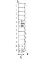
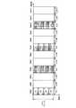
本実施の形態に係る基地局100の構成を図1に示す。基地局100は、マルチキャリア信号であるOFDMシンボルを構成する複数のサブキャリアを複数のRBに分け、それら複数のRBにおいて、RB毎にDchおよびLchを使用する。また、同一サブフレームでは、1つの移動局に対してDchまたはLchのいずれかが割り当てられる。(Embodiment 1)
The configuration of
基地局100において、Dchデータのための符号化部11および変調部12からなる符号化・変調部101−1〜101−n、Lchデータのための符号化部21および変調部22からなる符号化・変調部102−1〜102−n、および、復調部31および復号部32からなる復調・復号部115−1〜115−nは、基地局100が通信可能な移動局(MS)の数nだけ備えられる。 In
符号化・変調部101−1〜101−nにおいて、符号化部11は、移動局#1〜#n毎のDchデータ#1〜#nに対してターボ符号等の符号化処理を行い、変調部12は、符号化後のDchデータに対して変調処理を行ってDchデータシンボルを生成する。 In the encoding / modulation units 101-1 to 101-n, the
符号化・変調部102−1〜102−nにおいて、符号化部21は、移動局#1〜#n毎のLchデータ#1〜#nに対してターボ符号等の符号化処理を行い、変調部22は、符号化後のLchデータに対して変調処理を行ってLchデータシンボルを生成する。このときの符号化率および変調方式は、適応制御部116から入力されるMCS(Modulation and Coding Scheme:MCS)情報に従う。 In the encoding / modulation units 102-1 to 102-n, the
割当部103は、適応制御部116からの制御に従って、DchデータシンボルおよびLchデータシンボルを、OFDMシンボルを構成する各サブキャリアに割り当てて多重部104に出力する。この際、割当部103は、DchデータシンボルおよびLchデータシンボルを、RB毎にそれぞれまとめて割り当てる。また、割当部103は、1つの移動局のDchデータシンボルに複数のDchを使用する場合、連続したチャネル番号のDchを使用する。つまり、割当部103は、チャネル番号が連続する異なる複数のDchを1つの移動局のDchデータシンボルに割り当てる。なお、各RBではDchおよびLchの配置位置が予め対応付けられている。つまり、割当部103は、DchおよびLchと、RBとの対応付けである配置パターンを予め保持し、配置パターンに従ってDchデータシンボルおよびLchデータシンボルを各RBに割り当てる。本実施の形態におけるDchの配置方法の詳細については後述する。また、割当部103は、Dchデータシンボルの割当情報(どの移動局のDchデータシンボルをどのRBに割り当てたかを示す情報)およびLchデータシンボルの割当情報(どの移動局のLchデータシンボルをどのRBに割り当てたかを示す情報)を制御情報生成部105に出力する。例えば、Dchデータシンボルの割当情報には、連続したチャネル番号のうち先頭のチャネル番号および末尾のチャネル番号のみが含まれる。
制御情報生成部105は、Dchデータシンボルの割当情報、Lchデータシンボルの割当情報、および、適応制御部116から入力されるMCS情報からなる制御情報を生成して符号化部106に出力する。 Control
符号化部106は、制御情報に対して符号化処理を行い、変調部107は、符号化後の制御情報に対して変調処理を行って多重部104に出力する。 The
多重部104は、割当部103から入力される各データシンボルに制御情報を多重してIFFT(Inverse Fast Fourier Transform)部108に出力する。なお、制御情報の多重は、例えばサブフレーム毎に行われる。また、本実施の形態においては、制御情報の多重は、時間多重または周波数多重のいずれでもよい。 Multiplexing
IFFT部108は、制御情報およびデータシンボルが割り当てられた複数のRBを構成する複数のサブキャリアに対してIFFTを行って、マルチキャリア信号であるOFDMシンボルを生成する。
CP(Cyclic Prefix)付加部109は、OFDMシンボルの後尾部分と同じ信号をCPとしてOFDMシンボルの先頭に付加する。 CP (Cyclic Prefix) adding
無線送信部110は、CP付加後のOFDMシンボルに対しD/A変換、増幅およびアップコンバート等の送信処理を行ってアンテナ111から各移動局へ送信する。
一方、無線受信部112は、最大n個の移動局から同時に送信されたn個のOFDMシンボルをアンテナ111を介して受信し、これらのOFDMシンボルに対しダウンコンバート、A/D変換等の受信処理を行う。 On the other hand, the
CP除去部113は、受信処理後のOFDMシンボルからCPを除去する。
FFT(Fast Fourier Transform)部114は、CP除去後のOFDMシンボルに対してFFTを行って、周波数領域で多重された移動局毎の信号を得る。ここで、各移動局は互いに異なるサブキャリアまたは互いに異なるRBを用いて信号を送信しており、移動局毎の信号にはそれぞれ、各移動局から報告されるRB毎の受信品質情報が含まれている。なお、各移動局では、RB毎の受信品質を、受信SNR、受信SIR、受信SINR、受信CINR、受信電力、干渉電力、ビット誤り率、スループット、所定の誤り率を達成できるMCS等により測定することができる。また、受信品質情報は、CQI(Channel Quality Indicator)やCSI(Channel State Information)等と表されることがある。 An FFT (Fast Fourier Transform)
復調・復号部115−1〜115−nにおいて、復調部31は、FFT後の信号に対して復調処理を行い、復号部32は、復調後の信号に対して復号処理を行う。これにより、受信データが得られる。受信データのうち受信品質情報が適応制御部116に入力される。 In the demodulation / decoding units 115-1 to 115-n, the
適応制御部116は、各移動局から報告されたRB毎の受信品質情報に基づいてLchデータに対する適応制御を行う。すなわち、適応制御部116は、RB毎の受信品質情報に基づいて、符号化・変調部102−1〜102−nに対しては、所要誤り率を満たすことができるMCSの選択をRB毎に行ってMCS情報を出力する。また、適応制御部116は、割当部103に対しては、Max SIR法やProportional Fairness法等のスケジューリングアルゴリズムを用いて、Lchデータ#1〜#nの各々をどのRBに割り当てるかを決定する周波数スケジューリングを行う。また、適応制御部116は、RB毎のMCS情報を制御情報生成部105に出力する。 The
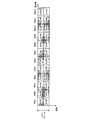
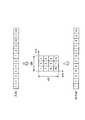
次に、本実施の形態に係る移動局200の構成を図2に示す。移動局200は、複数のRBに分けられた複数のサブキャリアで構成されるOFDMシンボルであるマルチキャリア信号を基地局100(図1)から受信する。また、複数のRBにおいて、RB毎にDchおよびLchが使用される。また、同一サブフレームでは、移動局200に対してDchまたはLchのいずれかが割り当てられる。 Next, FIG. 2 shows the configuration of
移動局200において、無線受信部202は、基地局100から送信されたOFDMシンボルをアンテナ201を介して受信し、OFDMシンボルに対しダウンコンバート、A/D変換等の受信処理を行う。 In
CP除去部203は、受信処理後のOFDMシンボルからCPを除去する。
FFT部204は、CP除去後のOFDMシンボルに対してFFTを行って、制御情報およびデータシンボルが多重された受信信号を得る。
分離部205は、FFT後の受信信号を制御信号とデータシンボルとに分離する。そして、分離部205は、制御信号を復調・復号部206に出力し、データシンボルをデマッピング部207に出力する。 Separating
復調・復号部206において、復調部41は、制御信号に対して復調処理を行い、復号部42は、復調後の信号に対して復号処理を行う。ここで、制御情報は、Dchデータシンボルの割当情報、Lchデータシンボルの割当情報、および、MCS情報を含む。そして、復調・復号部206は、制御情報のうちDchデータシンボルの割当情報、Lchデータシンボルの割当情報をデマッピング部207に出力する。 In the demodulation /
デマッピング部207は、復調・復号部206から入力される割当情報に基づいて、分離部205から入力されるデータシンボルが割り当てられている複数のRBから、自局に割り当てられたデータシンボルを抽出する。なお、基地局100(図1)と同様、各RBでは、DchおよびLchの配置位置が予め対応付けられている。つまり、デマッピング部207は、基地局100の割当部103と同一の配置パターンを予め保持し、配置パターンに従ってDchデータシンボルおよびLchデータシンボルを複数のRBから抽出する。また、上述したように、基地局100の割当部103(図1)では、1つの移動局のDchデータシンボルに複数のDchを使用する場合、連続したチャネル番号のDchを使用する。また、基地局100からの制御情報に含まれる割当情報には、連続したチャネル番号のうち先頭のチャネル番号および末尾のチャネル番号のみが示されている。そこで、デマッピング部207は、割当情報に示される先頭のチャネル番号および末尾のチャネル番号に基づいて、自局に割り当てられたDchデータシンボルに使用されたDchを特定する。そして、デマッピング部207は、特定されたDchのチャネル番号と対応付けられたRBを抽出し、抽出したRBに割り当てられているデータシンボルを復調・復号部208に出力する。 Based on the allocation information input from demodulation /
復調・復号部208において、復調部51は、デマッピング部207から入力されたデータシンボルに対して復調処理を行い、復号部52は、復調後の信号に対して復号処理を行う。これにより、受信データが得られる。 In demodulation /
一方、符号化・変調部209において、符号化部61は、送信データに対してターボ符号等の符号化処理を行い、変調部62は、符号化後の送信データに対して変調処理を行ってデータシンボルを生成する。ここで、移動局200は、他の移動局と互いに異なるサブキャリアまたは互いに異なるRBを用いて送信データを送信しており、送信データには、RB毎の受信品質情報が含まれている。 On the other hand, in the encoding /
IFFT部210は、符号化・変調部209から入力されるデータシンボルが割り当てられた複数のRBを構成する複数のサブキャリアに対してIFFTを行って、マルチキャリア信号であるOFDMシンボルを生成する。
CP付加部211は、OFDMシンボルの後尾部分と同じ信号をCPとしてOFDMシンボルの先頭に付加する。
無線送信部212は、CP付加後のOFDMシンボルに対しD/A変換、増幅およびアップコンバート等の送信処理を行ってアンテナ201から基地局100(図1)へ送信する。
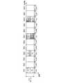
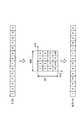
次に、本実施の形態におけるDchのチャネルの配置方法について説明する。以下の説明では、図3に示すように、1OFDMシンボルを構成する複数のサブキャリアがRB#1〜#12の12個のRBに均等に分割して構成される場合を一例に挙げて説明する。また、各RBによりLch#1〜#12またはDch#1〜#12が構成され、適応制御部116により、各移動局が使用するチャネルを制御する。また、図3に示す各RBにおけるLchの構成、および、以下に示す各RBにおけるDchの構成は、割当部103に予め対応付けられている。 Next, a Dch channel arrangement method in the present embodiment will be described. In the following description, as shown in FIG. 3, a case where a plurality of subcarriers constituting one OFDM symbol are equally divided into 12
ここで、LchについてはRB単位で周波数スケジューリングが行われるため、Lchに使用される各RBには、それぞれ1つの移動局だけへのLchデータシンボルが含まれる。つまり、1つのRBにより1つの移動局に対する1つのLchが構成される。よって、図3に示すように、RB#1〜#12によりLch#1〜#12がそれぞれ配置される。つまり、各Lchの割当単位は「1RB×1サブフレーム」である。 Here, since frequency scheduling is performed in units of RBs for Lch, each RB used for Lch includes an Lch data symbol for only one mobile station. That is, one Lch for one mobile station is constituted by one RB. Therefore, as shown in FIG. 3,
一方、Dchについては周波数ダイバーシチ送信が行われるため、Dchに使用されるRBには、それぞれ、複数のDchデータシンボルが含まれる。ここでは、Dchに使用される各RBは2つのサブブロックに時間分割され、各サブブロックに異なるDchがそれぞれ配置される。つまり、1RBでは複数の異なるDchが時間多重される。また、異なる2つのRBのサブブロックにより1つのDchが構成される。つまり、各Dchの割当単位は「(1RB×1/2サブフレーム)×2」であり、各Lchの割当単位と同一である。 On the other hand, since frequency diversity transmission is performed for Dch, each RB used for Dch includes a plurality of Dch data symbols. Here, each RB used for Dch is time-divided into two subblocks, and a different Dch is arranged in each subblock. That is, in 1 RB, a plurality of different Dch are time-multiplexed. In addition, one Dch is configured by two different RB sub-blocks. That is, the allocation unit of each Dch is “(1RB × ½ subframe) × 2”, which is the same as the allocation unit of each Lch.
<配置方法1(図4)>
本配置方法では、1RBに連続するチャネル番号のDchを配置する。<Arrangement method 1 (FIG. 4)>
In this arrangement method, Dch's with channel numbers continuous to 1RB are arranged.
まず、Dchのチャネル番号とそのDchが配置されるRBのRB番号との関係式を示す。 First, a relational expression between the channel number of Dch and the RB number of RB where the Dch is arranged is shown.
1RBあたりのサブブロック分割数がNdである場合、連続するチャネル番号のDch#(Nd・(k−1)+1),Dch#(Nd・(k−1)+2),…,Dch#(Nd・k)が配置されるRBのRB番号jは、次式(1)で与えられる。
すなわち、同一のRBに配置され、かつ、チャネル番号が連続するNd個のDch#(Nd・(k−1)+1),Dch#(Nd・(k−1)+2),…,Dch#(Nd・k)は、周波数領域でfloor(Nrb/Nd)RBの間隔で離れたNd個のRB#(j)に分散配置される。 That is, Nd Dch # (Nd · (k−1) +1), Dch # (Nd · (k−1) +2),..., Dch # () arranged in the same RB and having consecutive channel numbers. Nd · k) is distributed and arranged in Nd RB # (j) separated by a floor (Nrb / Nd) RB interval in the frequency domain.
ここでは、Nrb=12、Nd=2であるので、上式(1)は、j=k+6・p (p=0,1)となる。ただし、k=1,2,…,6である。これにより、チャネル番号が連続する2個のDch#(2k−1)およびDch#(2k)は、周波数領域で6(=12/2)RBの間隔で離れたRB#(k)およびRB#(k+6)の2RBに分散配置される。 Here, since Nrb = 12, Nd = 2, the above equation (1) becomes j = k + 6 · p (p = 0, 1). However, k = 1, 2,... As a result, two Dch # (2k-1) and Dch # (2k) with consecutive channel numbers are separated from each other by RB # (k) and RB # separated by an interval of 6 (= 1/2) RB in the frequency domain. Distributedly arranged in 2RB of (k + 6).
具体的には、図4に示すように、Dch#1,#2がRB#1(RB#7)に配置され、Dch#3,#4がRB#2(RB#8)に配置され、Dch#5,#6がRB#3(RB#9)に配置され、Dch#7,#8がRB#4(RB#10)に配置され、Dch#9,#10がRB#5(RB#11)に配置され、Dch#11,#12がRB#6(RB#12)に配置される。 Specifically, as shown in FIG. 4,
次に、1つの移動局のDchデータシンボルに対して、Dch#1〜#4の連続する4個のDchを使用する場合の基地局100の割当部103(図1)における割当例を図5に示す。ここで、割当部103は、図4に示すDchの配置パターンを保持し、図4に示す配置パターンに従ってDchデータシンボルをRBに割り当てる。 Next, an allocation example in the allocation unit 103 (FIG. 1) of the
割当部103は、図5に示すように、Dchデータシンボルを、Dch#1を構成するRB#1のサブブロックおよびRB#7のサブブロックと、Dch#2を構成するRB#1のサブブロックおよびRB#7のサブブロックと、Dch#3を構成するRB#2のサブブロックおよびRB#8のサブブロックと、Dch#4を構成するRB#2のサブブロックおよびRB#8のサブブロックとに割り当てる。すなわち、Dchデータシンボルは、図5に示すように、RB#1,#2,#7,#8に割り当てられる。 As shown in FIG. 5, allocating
また、割当部103は、図5に示すように、Dchデータシンボルが割り当てられたRB以外の残りのRB#3〜#6およびRB#9〜#12にLchデータシンボルを割り当てる。つまり、図3に示すLch#3〜#6およびLch#9〜#12がLchデータシンボルに使用される。 Further, as shown in FIG. 5, allocating
次いで、移動局200に対して、Dch#1〜#4の連続する4個のDchを使用したDchデータシンボルが割り当てられた場合の、移動局200のデマッピング部207(図2)における抽出例について説明する。ここで、デマッピング部207は、割当部103と同様、図4に示すDchの配置パターンを保持し、図4に示す配置パターンに従ってDchデータシンボルを複数のRBから抽出する。また、基地局100から移動局200に通知されるDchデータシンボルの割当情報には、先頭のチャネル番号であるDch#1と、末尾のチャネル番号であるDch#4とが示される。 Next, an example of extraction in demapping section 207 (FIG. 2) of
デマッピング部207は、Dchデータシンボルの割当情報に示されるDchのチャネル番号がDch#1およびDch#4であるため、自局宛てのDchデータシンボルに使用されているDchがDch#1〜#4の連続する4個のDchであることを特定する。そして、デマッピング部207は、割当部103と同様にして、図5に示すように、RB#1のサブブロックおよびRB#7のサブブロックで構成されるDch#1と、RB#1のサブブロックおよびRB#7のサブブロックで構成されるDch#2と、RB#2のサブブロックおよびRB#8のサブブロックで構成されるDch#3と、RB#2のサブブロックおよびRB#8のサブブロックで構成されるDch#4とを抽出する。すなわち、デマッピング部207は、図5に示すように、RB#1,#2,#7,#8に割り当てられたDchデータシンボルを自局宛てのデータシンボルとして抽出する。 Since the Dch channel numbers indicated in the Dch data symbol allocation information are
このように、本配置方法では、1RBに連続するチャネル番号のDchが配置されるため、1つの移動局が複数のDchを使用する場合、1つのRBのサブブロックがすべて使用された後に別のRBが使用される。これにより、1RBを構成する複数のサブブロックのうち、一部のサブブロックにデータシンボルが割り当てられる一方、それ以外のサブブロックが使用されなくなることを最小限にすることができる。よって、本配置方法によれば、Lchにおける周波数スケジューリング送信とDchにおける周波数ダイバーシチ送信とを同時に行う際に、周波数ダイバーシチ送信を行うためのチャネルのリソース利用効率の低下を防ぐことができる。また、本配置方法によれば、Dchに使用されるRBの通信リソースの利用効率の低下を防ぐことができるため、Lchに使用できるRBの数が多くなり、より多くの周波数帯域に対して周波数スケジューリングを行うことができる。 As described above, in this arrangement method, Dchs having consecutive channel numbers are arranged in 1 RB. Therefore, when one mobile station uses a plurality of Dchs, another subblock of one RB is used and then another channel is used. RB is used. Thereby, it is possible to minimize the fact that data symbols are assigned to some of the sub-blocks constituting one RB, while other sub-blocks are not used. Therefore, according to this arrangement method, it is possible to prevent a reduction in channel resource utilization efficiency for performing frequency diversity transmission when performing frequency scheduling transmission in Lch and frequency diversity transmission in Dch simultaneously. Also, according to the present arrangement method, it is possible to prevent a reduction in the utilization efficiency of communication resources of RBs used for Dch, so that the number of RBs that can be used for Lch increases, and the frequency for more frequency bands is increased. Scheduling can be performed.
また、本配置方法によれば、1つの移動局が複数のDchを使用する場合、チャネル番号が連続する複数のDchが周波数領域で連続したRBに配置される。このため、Lchに使用できるRB、すなわち、Dchで使用したRB以外の残りのRBについても周波数上で連続する。例えば、伝搬路の周波数選択性が緩やかな場合や各RBの帯域幅が狭い場合、周波数選択性フェージングの相関帯域幅に対してRBの帯域幅が狭くなる。このとき、回線品質が高い周波数帯域では回線品質が良いRBが連続する。よって、周波数選択性フェージングの相関帯域幅に対してRBの帯域幅が狭くなる場合に、本配置方法を用いることで、周波数領域で連続したRBをLchに使用することができるため、周波数スケジューリング効果をより向上することができる。 Also, according to this arrangement method, when one mobile station uses a plurality of Dch, a plurality of Dch with consecutive channel numbers are arranged in RBs continuous in the frequency domain. For this reason, the RBs that can be used for the Lch, that is, the remaining RBs other than the RB used for the Dch are also continuous in frequency. For example, when the frequency selectivity of the propagation path is moderate or when the bandwidth of each RB is narrow, the bandwidth of the RB becomes narrower than the correlation bandwidth of frequency selective fading. At this time, RBs with good channel quality are continuous in a frequency band with high channel quality. Therefore, when the RB bandwidth is narrower than the correlation bandwidth of frequency selective fading, by using this arrangement method, RBs that are continuous in the frequency domain can be used for Lch. Can be further improved.
また、本配置方法によれば、連続したチャネル番号の複数のLchを割り当てることができる。このため、基地局が1つの移動局に複数のLchを割り当てる場合、連続したチャネル番号のうち先頭のチャネル番号および末尾のチャネル番号のみを基地局から移動局に通知すればよい。よって、Dchの割当結果を通知する場合と同様に、Lchの割当結果を通知するための制御情報を削減することができる。 Also, according to this arrangement method, a plurality of Lch's with consecutive channel numbers can be assigned. For this reason, when the base station assigns a plurality of Lchs to one mobile station, only the first channel number and the last channel number among consecutive channel numbers need be notified from the base station to the mobile station. Therefore, the control information for notifying the Lch allocation result can be reduced as in the case of notifying the Dch allocation result.
なお、本配置方法では、Dchを使用する場合に1RBを2分割する場合について説明したが、1RBの分割数は2に限らず、1RBを3分割以上に分割してもよい。例えば、Dchを使用する場合に1RBを3分割する場合の配置方法を図6に示す。図6に示すように、1RBに連続する3つのDchが配置されるため、本配置方法と同様の効果を得ることができる。また、図6に示すように、1Dchは3RBに分散して構成されるため、2分割の場合よりもダイバーシチ効果を向上することができる。 In this arrangement method, the case where 1 RB is divided into two when using Dch has been described. However, the number of divisions of 1 RB is not limited to 2, and 1 RB may be divided into three or more. For example, FIG. 6 shows an arrangement method when 1RB is divided into three when Dch is used. As shown in FIG. 6, since three Dch continuous in 1 RB are arranged, the same effect as this arrangement method can be obtained. Also, as shown in FIG. 6, since 1Dch is configured to be distributed in 3 RBs, the diversity effect can be improved as compared with the case of two divisions.
<配置方法2(図8)>
本配置方法では、チャネル番号が連続する異なる複数のDchを1つのRBに配置する点は配置方法1と同じであるが、上記1つのRBと周波数領域で分散配置されたRBに、前記複数のDchのうち最小番号または最大番号のDchとチャネル番号が連続するDchを配置する点が配置方法1と相違する。<Arrangement method 2 (FIG. 8)>
This arrangement method is the same as the
本配置方法では、配置方法1(図4)と同様、連続するチャネル番号のDchが同一RBに配置される。すなわち、図8に示すDch#1〜#12のうち、(Dch#1,#2)、(Dch#3,#4)、(Dch#5,#6)、(Dch#7,#8)、(Dch#9,#10)および(Dch#11,#12)がそれぞれ同一RBで構成されるDchの組み合わせである。 In this arrangement method, Dch of consecutive channel numbers are arranged in the same RB as in arrangement method 1 (FIG. 4). That is, among
さらに、上記複数の組み合わせのうち、一方の組み合わせに含まれるDchのうち最小番号または最大番号のDchとチャネル番号が連続するDchが含まれる組み合わせを周波数領域で分散したRBに配置する。すなわち、連続するチャネル番号のDch#2およびDch#3がそれぞれ含まれる(Dch#1,#2)と(Dch#3,4)とが分散した異なるRBに配置され、連続するチャネル番号のDch#4およびDch#5がそれぞれ含まれる(Dch#3,#4)と(Dch#5,#6)とが分散した異なるRBに配置され、連続するチャネル番号のDch#6およびDch#7がそれぞれ含まれる(Dch#5,#6)と(Dch#7,#8)とが分散した異なるRBに配置され、連続するチャネル番号のDch#8およびDch#9がそれぞれ含まれる(Dch#7,#8)と(Dch#9,#10)とが分散した異なるRBに配置され、連続するチャネル番号のDch#10およびDch#11がそれぞれ含まれる(Dch#9,#10)と(Dch#11,#12)とが分散した異なるRBに配置される。 Furthermore, among the plurality of combinations, among the Dch included in one of the combinations, a combination including a Dch having a continuous channel number and a Dch having a minimum number or a maximum number is arranged in an RB distributed in the frequency domain. That is, (
ここで、配置方法1と同様にして、Dchのチャネル番号とそのDchが配置されるRBのRB番号との関係式を示す。 Here, similarly to the
組み合わせkに含まれる連続するチャネル番号のDch#(Nd・(k−1)+1),Dch#(Nd・(k−1)+2),…,Dch#(Nd・k)が配置されるRBのRB番号jは、次式(2)で与えられる。
ここでは、Nrb=12、Nd=2であるので、上式(2)は、j=q(k)+6・p (p=0,1)となる。また、q(k)は、図7に示すように、2行×3列のブロックインタリーバにより与えられる。すなわち、図7に示すように、k=1,2,3,4,5,6に対して、q(k)=1,4,2,5,3,6が得られる。よって、チャネル番号が連続する2つのDch#(2k−1)およびDch#(2k)は、周波数領域で6(=12/2)RBの間隔で離れたRB#(q(k))およびRB#(q(k)+6)の2RBに分散配置される。 Here, since Nrb = 12, Nd = 2, the above equation (2) becomes j = q (k) + 6 · p (p = 0, 1). Further, q (k) is given by a 2 × 3 block interleaver as shown in FIG. That is, as shown in FIG. 7, q (k) = 1, 4, 2, 5, 3, 6 is obtained for k = 1, 2, 3, 4, 5, 6. Therefore, two Dch # (2k-1) and Dch # (2k) having consecutive channel numbers are divided into RB # (q (k)) and RB separated by an interval of 6 (= 1/2/2) RB in the frequency domain. # (Q (k) +6) is distributed in 2 RBs.
具体的には、例えば、図8に示すように、Dch#1,#2がRB#1(RB#7)に配置され、Dch#5,#6がRB#2(RB#8)に配置され、Dch#9,#10がRB#3(RB#9)に配置され、Dch#3,#4がRB#4(RB#10)に配置され、Dch#7,#8がRB#5(RB#11)に配置され、Dch#11,#12がRB#6(RB#12)に配置される。 Specifically, for example, as shown in FIG. 8,
次に、配置方法1と同様、1つの移動局のDchデータシンボルに対して、Dch#1〜#4の連続する4個のDchを使用する場合の基地局100の割当部103(図1)における割当例を図9に示す。ここで、割当部103は、図8に示すDchの配置パターンを保持し、図8に示す配置パターンに従ってDchデータシンボルをRBに割り当てる。 Next, as in
割当部103は、図9に示すように、Dch#1を構成するRB#1のサブブロックおよびRB#7のサブブロックと、Dch#2を構成するRB#1のサブブロックおよびRB#7のサブブロックと、Dch#3を構成するRB#4のサブブロックおよびRB#10のサブブロックと、Dch#4を構成するRB#4のサブブロックおよびRB#10のサブブロックとにDchデータシンボルを割り当てる。すなわち、Dchデータシンボルは、図9に示すように、RB#1,#4,#7,#10に割り当てられる。 As shown in FIG. 9, allocating
また、割当部103は、図9に示すように、Dchデータシンボルが割り当てられたRB以外の残りのRB#2、#3、#5、#6、#8、#9、#11,#12にLchデータシンボルを割り当てる。つまり、図3に示すLch#2、#3、#5、#6、#8、#9、#11,#12がLchデータシンボルに使用される。 Further, as shown in FIG. 9,
次いで、配置方法1と同様、移動局200に対して、Dch#1〜#4の連続する4個のDchを使用したDchデータシンボルが割り当てられた場合の、移動局200のデマッピング部207(図2)における抽出例について説明する。ここで、デマッピング部207は、割当部103と同様、図8に示すDchの配置パターンを保持し、図8に示す配置パターンに従ってDchデータシンボルを複数のRBから抽出する。また、配置方法1と同様、基地局100から移動局200に通知されるDchデータシンボルの割当情報には、先頭のチャネル番号であるDch#1と、末尾のチャネル番号であるDch#4とが示される。 Next, similarly to the
デマッピング部207は、Dchデータシンボルの割当情報に示されるDchのチャネル番号がDch#1およびDch#4であるため、自局宛てのDchデータシンボルに使用されているDchがDch#1〜#4の連続する4個のDchであることを特定する。そして、デマッピング部207は、割当部103と同様にして、図9に示すように、RB#1のサブブロックおよびRB#7のサブブロックで構成されるDch#1と、RB#1のサブブロックおよびRB#7のサブブロックで構成されるDch#2と、RB#4のサブブロックおよびRB#10のサブブロックで構成されるDch#3と、RB#4のサブブロックおよびRB#10のサブブロックで構成されるDch#4とを抽出する。すなわち、デマッピング部207は、図9に示すように、RB#1,#4,#7,#10に割り当てられたDchデータシンボルを自局宛てのデータシンボルとして抽出する。 Since the Dch channel numbers indicated in the Dch data symbol allocation information are
本配置方法では、配置方法1と同様に、Dchデータシンボルが4つのRBに割り当てられ、Lchデータシンボルが8つのRBに割り当てられる。ただし、本配置方法では、図9に示すように、DchデータシンボルがRB#1、RB#4、RB#7およびRB#10に3RB毎に分散して割り当てられるため、配置方法1(図5)よりも周波数ダイバーシチ効果を向上することができる。また、Dchデータシンボルが分散されたRBに割り当てられることによって、図9に示すように、Lchデータシンボルも分散されるため、より広い帯域に渡るRBを使用して周波数スケジューリングを行うことが可能となる。 In this arrangement method, as in
このようにして、本配置方法では、チャネル番号が連続する複数の異なるDchが配置された1つのRBと周波数領域で分散配置されたRBに、上記複数の異なるDchのうち最小番号または最大番号のDchとチャネル番号が連続するDchを配置する。このため、1つの移動局のデータシンボルに対して複数のDchを使用する場合でも、各RBのサブブロックの一部が使用されなくなることを防ぎつつ、データシンボルを広い帯域に分散して割り当てることができる。よって、本配置方法によれば、配置方法1と同様の効果を得ることができ、さらに、周波数ダイバーシチ効果を向上することができる。また、本配置方法によれば、Dchに使用するRBが分散されるため、Dchに使用されるRB以外の残りのRB、つまり、Lchとして使用されるRBも分散させることができる。これより、本配置方法によれば、周波数スケジューリング効果を向上することができる。 In this way, in this arrangement method, the minimum number or the maximum number of the plurality of different Dch is assigned to one RB in which a plurality of different Dch having consecutive channel numbers are arranged and RB distributed in the frequency domain. A Dch having a continuous channel number with the Dch is arranged. For this reason, even when a plurality of Dchs are used for data symbols of one mobile station, data symbols are distributed and allocated over a wide band while preventing a part of each RB subblock from being used. Can do. Therefore, according to the present arrangement method, the same effect as the
なお、本配置方法では、Dchを使用する場合に1RBを2分割する場合について説明したが、1RBの分割数は2に限らず、1RBを3分割以上に分割してもよい。例えば、Dchを使用する場合に1RBを3分割する場合の配置方法を図10に示す。図10に示すように、連続するDchを含む異なるRBは、周波数領域に分散されるため、本配置方法と同様の効果を得ることができる。また、図10に示すように、1Dchは3RBに分散して構成されるため、2分割の場合よりもダイバーシチ効果を向上することができる。 In this arrangement method, the case where 1 RB is divided into two when using Dch has been described. However, the number of divisions of 1 RB is not limited to 2, and 1 RB may be divided into three or more. For example, FIG. 10 shows an arrangement method for dividing 1 RB into three when using Dch. As shown in FIG. 10, since different RBs including consecutive Dchs are distributed in the frequency domain, the same effect as in the present arrangement method can be obtained. Further, as shown in FIG. 10, since 1Dch is configured to be distributed in 3RBs, the diversity effect can be improved as compared with the case of two divisions.
<配置方法3(図11)>
本配置方法では、連続するチャネル番号のDchを異なるRBに配置し、かつ、1RBに所定数以内のチャネル番号のDchを配置する。<Arrangement method 3 (FIG. 11)>
In this arrangement method, Dchs having consecutive channel numbers are arranged in different RBs, and Dchs having channel numbers within a predetermined number are arranged in one RB.
以下、具体的に説明する。ここでは、所定数を2とする。つまり、同一RB内に含まれる互いに異なるDchのチャネル番号の差を2以内とする。 This will be specifically described below. Here, the predetermined number is 2. That is, the difference between the channel numbers of different Dch included in the same RB is set to 2 or less.
まず、Dchのチャネル番号とそのDchが配置されるRBのRB番号との関係式を示す。 First, a relational expression between the channel number of Dch and the RB number of RB where the Dch is arranged is shown.
組み合わせkに含まれる互いに異なるDchが配置されるRBのRB番号jは、配置方法2と同様の式(2)で与えられる。ただし、配置方法2では、組み合わせkに含まれるDchのチャネル番号は連続するのに対し、本配置方法では、組み合わせkに含まれるDchのチャネル番号は所定数だけ離れる。また、組み合わせ番号kは、チャネル番号がより小さいDchの組み合わせに対して、より小さい値が付与される。 The RB number j of the RB in which different Dch included in the combination k is arranged is given by the same expression (2) as in the
ここでは、Nrb=12、Nd=2であるので、配置方法2と同様、j=q(k)+6・p (p=0,1)となる。ただし、k=1,2,…,6である。また、q(k)も、配置方法2と同様、図7に示す2行×3列のブロックインタリーバにより与えられる。よって、組み合わせkに含まれるDchは、周波数領域で6(=12/2)RBの間隔で離れたRB#(q(k))およびRB#(q(k)+6)の2RBに分散配置される。ただし、所定数が2であるので、組み合わせ1(k=1)は(Dch#1,#3)となり、組み合わせ2(k=2)は(Dch#2,#4)となる。組み合わせ3〜6についても同様である。 Here, since Nrb = 12, Nd = 2, similarly to the
よって、図11に示すように、Dch#1,#3がRB#1(RB#7)に配置され、Dch#5,#7がRB#2(RB#8)に配置され、Dch#9,#11がRB#3(RB#9)に配置され、Dch#2,#4がRB#4(RB#10)に配置され、Dch#6,#8がRB#5(RB#11)に配置され、Dch#10,#12がRB#6(RB#12)に配置される。 Therefore, as shown in FIG. 11,
次に、1つの移動局のDchデータシンボルに対して、Dch#1,#2の連続する2個のDchを使用する場合、つまり、1つの移動局のDchデータシンボルに使用するDchの数が少ない場合の基地局100の割当部103(図1)における割当方法を図12に示す。ここで、割当部103は、図11に示すDchの配置パターンを保持し、図11に示す配置パターンに従ってDchデータシンボルをRBに割り当てる。 Next, when two consecutive Dchs of
割当部103は、図12に示すように、Dch#1を構成するRB#1のサブブロックおよびRB#7のサブブロックと、Dch#2を構成するRB#4のサブブロックおよびRB#10のサブブロックとにDchデータシンボルを割り当てる。すなわち、Dchデータシンボルは、図12に示すように、周波数領域で分散したRB#1,#4,#7,#10に割り当てられる。 As shown in FIG. 12, allocating
次いで、移動局200に対して、Dch#1,#2の連続する2個のDchを使用したDchデータシンボルが割り当てられた場合の、移動局200のデマッピング部207(図2)における抽出例について説明する。ここで、デマッピング部207は、割当部103と同様、図11に示すDchの配置パターンを保持し、図11に示す配置パターンに従ってDchデータシンボルを複数のRBから抽出する。また、基地局100から移動局200に通知されるDchデータシンボルの割当情報には、先頭のチャネル番号であるDch#1と、末尾のチャネル番号であるDch#2とが示される。 Next, an example of extraction in the demapping unit 207 (FIG. 2) of the
デマッピング部207は、Dchデータシンボルの割当情報に示されるDchのチャネル番号がDch#1およびDch#2であるため、自局宛てのDchデータシンボルに使用されているDchがDch#1,#2の連続する2個のDchであることを特定する。そして、デマッピング部207は、割当部103と同様にして、図12に示すように、RB#1のサブブロックおよびRB#7のサブブロックで構成されるDch#1と、RB#4のサブブロックおよびRB#10のサブブロックで構成されるDch#2とを抽出する。すなわち、デマッピング部207は、図12に示すように、周波数領域で分散したRB#1,#4,#7,#10に割り当てられたDchデータシンボルを自局宛てのデータシンボルとして抽出する。 Since the Dch channel numbers indicated in the Dch data symbol assignment information are
このように、1つの移動局のDchデータシンボルに対して使用するDchの数が少ない場合、つまり、割り当てられるRBが少ない場合には、全帯域に対する通信リソースの利用効率低下の影響が少ない。よって、RB内で割り当てられたサブブロック以外のサブブロックが使用されない可能性があるものの周波数ダイバーシチ効果を優先して得ることができる。 As described above, when the number of Dch used for the Dch data symbol of one mobile station is small, that is, when the number of RBs allocated is small, the influence of the communication resource utilization efficiency on the entire band is small. Therefore, although the sub-blocks other than the sub-blocks allocated in the RB may not be used, the frequency diversity effect can be obtained with priority.
一方、1つの移動局のDchデータシンボルに対して、Dch#1〜#4の連続する4個のDchを使用する場合、つまり、1つの移動局のDchデータシンボルに使用するDchの数が多い場合の基地局100の割当部103(図1)における割当例を図13に示す。ここで、割当部103は、図11に示すDchの配置パターンを保持し、図11に示す配置パターンに従ってDchデータシンボルをRBに割り当てる。 On the other hand, when four consecutive Dchs of
割当部103は、図13に示すように、Dch#1を構成するRB#1のサブブロックおよびRB#7のサブブロックと、Dch#2を構成するRB#4のサブブロックおよびRB#10のサブブロックと、Dch#3を構成するRB#1のサブブロックおよびRB#7のサブブロックと、Dch#4を構成するRB#4のサブブロックおよびRB#10のサブブロックとにDchデータシンボルを割り当てる。すなわち、Dchデータシンボルは、図13に示すように、図12と同様、周波数領域で分散したRB#1,#4,#7,#10に割り当てられる。また、図13では、RB#1,#4,#7,#10のすべてのサブブロックにDchデータシンボルが割り当てられる。 As shown in FIG. 13, allocating
次いで、移動局200に対して、Dch#1〜#4の連続する4個のDchを使用したDchデータシンボルが割り当てられた場合の、移動局200のデマッピング部207(図2)における抽出例について説明する。ここで、デマッピング部207は、割当部103と同様、図11に示すDchの配置パターンを保持し、図11に示す配置パターンに従ってDchデータシンボルを複数のRBから抽出する。また、基地局100から移動局200に通知されるDchデータシンボルの割当情報には、先頭のチャネル番号であるDch#1と、末尾のチャネル番号であるDch#4とが示される。 Next, an example of extraction in demapping section 207 (FIG. 2) of
デマッピング部207は、Dchデータシンボルの割当情報に示されるDchのチャネル番号がDch#1およびDch#4であるため、自局宛てのDchデータシンボルに使用されているDchがDch#1〜#4の連続する4個のDchであることを特定する。そして、デマッピング部207は、割当部103と同様にして、図13に示すように、RB#1のサブブロックおよびRB#7のサブブロックで構成されるDch#1と、RB#4のサブブロックおよびRB#10のサブブロックで構成されるDch#2と、RB#1のサブブロックおよびRB#7のサブブロックで構成されるDch#3と、RB#4のサブブロックおよびRB#10のサブブロックで構成されるDch#4とを抽出する。すなわち、デマッピング部207は、図13に示すように、RB#1,#4,#7,#10のすべてのサブブロックに割り当てられたDchデータシンボルを自局宛てのデータシンボルとして抽出する。 Since the Dch channel numbers indicated in the Dch data symbol allocation information are
このように、1つの移動局のDchデータシンボルに対して使用するDchの数が多い場合、つまり、割り当てられるRBが多い場合でも、周波数ダイバーシチ効果を得つつ、RB内のすべてのサブブロックを使用することができる。 In this way, when the number of Dch used for a Dch data symbol of one mobile station is large, that is, even when a large number of RBs are allocated, all sub-blocks in the RB are used while obtaining the frequency diversity effect. can do.
このようにして、本配置方法では、連続するチャネル番号のDchを異なるRBに配置し、1RBに所定数以内のチャネル番号のDchを配置する。これにより、1つの移動局のDchデータシンボルに使用されるDchの数が少ない場合には、周波数ダイバーシチ効果を向上させることができる。また、1つの移動局のDchデータシンボルに使用されるDchの数が多い場合でも、通信リソースの利用効率を低下させることなく、周波数ダイバーシチ効果を向上させることができる。 In this way, in this arrangement method, Dchs with consecutive channel numbers are arranged in different RBs, and Dchs with channel numbers within a predetermined number are arranged in one RB. Thereby, when the number of Dch used for the Dch data symbol of one mobile station is small, the frequency diversity effect can be improved. Further, even when the number of Dch used for the Dch data symbol of one mobile station is large, the frequency diversity effect can be improved without lowering the communication resource utilization efficiency.
なお、本配置方法では、Dchを使用する場合に1RBを2分割する場合について説明したが、1RBの分割数は2に限らず、1RBを3分割以上に分割してもよい。例えば、Dchを使用する場合に1RBを3分割する場合の配置方法を図14に示す。図14に示すように、連続するチャネル番号のDchが異なるRBに配置され、1RBに所定数2以内のチャネル番号のDchが配置されるため、本配置方法と同様の効果を得ることができる。また、図14に示すように、1Dchは3RBに分散して構成されるため、2分割の場合よりもダイバーシチ効果を向上することができる。 In this arrangement method, the case where 1 RB is divided into two when using Dch has been described. However, the number of divisions of 1 RB is not limited to 2, and 1 RB may be divided into three or more. For example, FIG. 14 shows an arrangement method for dividing 1 RB into three when using Dch. As shown in FIG. 14, Dchs with consecutive channel numbers are arranged in different RBs, and Dchs with a channel number within a
<配置方法4(図15)>
本配置方法では、チャネル番号が連続する異なる複数のDchを1つのRBに配置する点は配置方法1と同じであるが、同じDchが配置されたRBが帯域の両端から順番に割り当てられる点が配置方法1と相違する。<Arrangement method 4 (FIG. 15)>
This arrangement method is the same as the
本配置方法では、配置方法1(図4)と同様、連続するチャネル番号のDchが同一RBに配置される。すなわち、図15に示すDch#1〜#12のうち、(Dch#1,#2)、(Dch#3,#4)、(Dch#5,#6)、(Dch#7,#8)、(Dch#9,#10)および(Dch#11,#12)がそれぞれ同一RBで構成されるDchの組み合わせである。 In this arrangement method, Dch of consecutive channel numbers are arranged in the same RB as in arrangement method 1 (FIG. 4). That is, among
さらに、上記組み合わせのDchが配置される2つのRBを帯域の両端から順番に割り当てる。すなわち、図15に示すように、(Dch#1,#2)はRB#1とRB#12とに配置され、(Dch#3,#4)はRB#2とRB#11とに配置される。同様に、(Dch#5,#6)はRB#3とRB#10とに配置され、(Dch#7,#8)はRB#4とRB#9とに配置され、(Dch#9,#10)はRB#5とRB#8とに配置され、(Dch#11,#12)はRB#6とRB#7とに配置される。 Further, two RBs in which the Dch of the combination is arranged are assigned in order from both ends of the band. That is, as shown in FIG. 15, (
次に、配置方法1と同様、1つの移動局のDchデータシンボルに対して、Dch#1〜#4の連続する4個のDchを使用する場合の基地局100の割当部103における割当例を図16に示す。ここで、割当部103は、図15に示すDchの配置パターンを保持し、図15に示す配置パターンに従ってDchデータシンボルをRBに割り当てる。 Next, as in
割当部103は、図16に示すように、Dch#1を構成するRB#1のサブブロックおよびRB#12のサブブロックと、Dch#2を構成するRB#1のサブブロックおよびRB#12のサブブロックと、Dch#3を構成するRB#2のサブブロックおよびRB#11のサブブロックと、Dch#4を構成するRB#2のサブブロックおよびRB#11のサブブロックとにDchデータシンボルを割り当てる。すなわち、Dchデータシンボルは、図16に示すように、RB#1,#2,#11,#12に割り当てられる。 As shown in FIG. 16, allocating
また、割当部103は、図16に示すように、Dchデータシンボルが割り当てられたRB以外の残りのRB#3、#4、#5、#6、#7、#8、#9,#10にLchデータシンボルを割り当てる。つまり、図3に示すLch#3、#4、#5、#6、#7、#8、#9,#10がLchデータシンボルに使用される。 Further, as shown in FIG. 16,
次いで、配置方法1と同様、移動局200に対して、Dch#1〜#4の連続する4個のDchを使用したDchデータシンボルが割り当てられた場合の、移動局200のデマッピング部207(図2)における抽出例について説明する。ここで、デマッピング部207は、割当部103と同様、図15に示すDchの配置パターンを保持し、図15に示す配置パターンに従ってDchデータシンボルを複数のRBから抽出する。また、配置方法1と同様、基地局100から移動局200に通知されるDchデータシンボルの割当情報には、先頭のチャネル番号であるDch#1と、末尾のチャネル番号であるDch#4とが示される。 Next, similarly to the
デマッピング部207は、Dchデータシンボルの割当情報に示されるDchのチャネル番号がDch#1およびDch#4であるため、自局宛てのDchデータシンボルに使用されているDchがDch#1〜#4の連続する4個のDchであることを特定する。そして、デマッピング部207は、割当部103と同様にして、図16に示すように、RB#1のサブブロックおよびRB#12のサブブロックで構成されるDch#1と、RB#1のサブブロックおよびRB#12のサブブロックで構成されるDch#2と、RB#2のサブブロックおよびRB#11のサブブロックで構成されるDch#3と、RB#2のサブブロックおよびRB#11のサブブロックで構成されるDch#4とを抽出する。すなわち、デマッピング部207は、図16に示すように、RB#1,#2,#11,#12に割り当てられたDchデータシンボルを自局宛てのデータシンボルとして抽出する。 Since the Dch channel numbers indicated in the Dch data symbol allocation information are
本配置方法では、配置方法1および配置方法2と同様に、Dchデータシンボルが4つのRBに割り当てられ、Lchデータシンボルが8つのRBに割り当てられる。ただし、本配置方法では、図16に示すように、帯域の両端のRBにDchデータシンボルが割り当てられる。Dchデータシンボルが割り当てられるRBの間隔が配置方法1(図5)および配置方法2(図9)よりも広いため、周波数ダイバーシチ効果を向上することができる。また、Dchデータシンボルが帯域の両端のRBに割り当てられることによって、図16に示すように、Lchデータシンボルも分散されるため、より広い帯域に渡るRBを使用して周波数スケジューリングを行うことが可能となる。 In this arrangement method, as with
また、本配置方法によれば、Lchに使用できるRB、すなわち、Dchで使用したRB以外の残りのRBのすべてが周波数上で連続する。例えば、伝搬路の周波数選択性が緩やかな場合や各RBの帯域幅が狭い場合、周波数選択性フェージングの相関帯域幅に対してRBの帯域幅が狭くなる。このとき、回線品質が高い周波数帯域では回線品質が良いRBが連続する。よって、周波数選択性フェージングの相関帯域幅に対してRBの帯域幅が狭くなる場合に、本配置方法を用いることで、周波数領域で連続したRBをLchに使用することができるため、周波数スケジューリング効果をより向上することができる。 Further, according to this arrangement method, all the RBs that can be used for the Lch, that is, the remaining RBs other than the RB used for the Dch are continuous in frequency. For example, when the frequency selectivity of the propagation path is moderate or when the bandwidth of each RB is narrow, the bandwidth of the RB becomes narrower than the correlation bandwidth of frequency selective fading. At this time, RBs with good channel quality are continuous in a frequency band with high channel quality. Therefore, when the RB bandwidth is narrower than the correlation bandwidth of frequency selective fading, by using this arrangement method, RBs that are continuous in the frequency domain can be used for Lch. Can be further improved.
また、本配置方法によれば、連続したチャネル番号の複数のLchを割り当てることができる。このため、基地局が1つの移動局に複数のLchを割り当てる場合、連続したチャネル番号のうち先頭のチャネル番号および末尾のチャネル番号のみを基地局から移動局に通知すればよい。本配置方法ではLchに使用できるRBがすべて周波数上で連続するため、1つの移動局にすべてのLchを割り当てる場合でも上記の通知方法を用いることができる。よって、Dchの割当結果を通知する場合と同様に、Lchの割当結果を通知するための制御情報を削減することができる。 Also, according to this arrangement method, a plurality of Lch's with consecutive channel numbers can be assigned. For this reason, when the base station assigns a plurality of Lchs to one mobile station, only the first channel number and the last channel number among consecutive channel numbers need be notified from the base station to the mobile station. In this arrangement method, since all RBs that can be used for Lch are continuous in frequency, the above notification method can be used even when all Lchs are assigned to one mobile station. Therefore, the control information for notifying the Lch allocation result can be reduced as in the case of notifying the Dch allocation result.
なお、本配置方法では、Dchを使用する場合に1RBを2分割する場合について説明したが、1RBの分割数は2に限らず、1RBを3分割以上に分割してもよい。例えば、Dchを使用する場合に1RBを3分割する場合の配置方法を図17に、4分割する場合の配置方法を図18に示す。図17、図18に示すように、連続するDchを含む異なるRBは、帯域の両端から優先的に配置されるため、本配置方法と同様の効果を得ることができる。また、図17および図18に示すように、1Dchはそれぞれ3RB、4RBに分散して構成されるため、2分割の場合よりもダイバーシチ効果を向上することができる。 In this arrangement method, the case where 1 RB is divided into two when using Dch has been described. However, the number of divisions of 1 RB is not limited to 2, and 1 RB may be divided into three or more. For example, when using Dch, FIG. 17 shows an arrangement method for dividing 1 RB into three, and FIG. 18 shows an arrangement method for dividing four RBs. As shown in FIGS. 17 and 18, different RBs including consecutive Dchs are preferentially arranged from both ends of the band, so that the same effect as the present arrangement method can be obtained. Moreover, as shown in FIGS. 17 and 18, since 1Dch is configured to be distributed to 3RB and 4RB, respectively, the diversity effect can be improved as compared with the case of two divisions.
以上、本実施の形態における配置方法1〜4について説明した。 The
このように、本実施の形態によれば、Lchにおける周波数スケジューリング送信とDchにおける周波数ダイバーシチ送信とを同時に行う際に、周波数ダイバーシチ送信を行うためのチャネルの通信リソースの利用効率の低下を防ぐことができる。また、本実施の形態によれば、Dchに使用されるRBの利用効率の低下を防ぐことができるため、Lchに使用できるRBの数が多くなり、より多くの周波数帯域に対して周波数スケジューリングを行うことができる。 Thus, according to the present embodiment, when performing frequency scheduling transmission on Lch and frequency diversity transmission on Dch at the same time, it is possible to prevent a reduction in utilization efficiency of communication resources of a channel for performing frequency diversity transmission. it can. In addition, according to the present embodiment, it is possible to prevent a decrease in the utilization efficiency of RBs used for Dch, so that the number of RBs that can be used for Lch increases, and frequency scheduling is performed for more frequency bands. It can be carried out.
(実施の形態2)
本実施の形態では、実施の形態1の配置方法1と配置方法2とを通信環境に応じて切り替えて使用する場合について説明する。(Embodiment 2)
In the present embodiment, a case will be described in which the
上述したように、配置方法1の方が配置方法2よりもLchに使用できる周波数領域で連続したRBを多く確保することができる一方で、配置方法2の方が配置方法1よりも周波数ダイバーシチ効果が大きくなる。 As described above, the
具体的には、1つの移動局のDchデータシンボルに対してDch#1〜#4の連続する4個のDchを使用する場合、配置方法1(図5)では、RB#3〜#6およびRB#9〜#12の周波数領域で連続する4RBをLchに使用することができる一方で、DchデータシンボルがRB#1,#2およびRB#7,#8の周波数領域で連続した2RBに割り当てられてしまう。これに対し、配置方法2(図9)では、RB#2,#3、RB#5,#6、RB#8,#9およびRB#11,#12の周波数領域で連続する2RBしかLchに使用することができない一方で、DchデータシンボルがRB#1、#4、#7,#10に3RB毎に分散して割り当てられる。 Specifically, when four consecutive Dchs of
このように、配置方法1および配置方法2では、周波数ダイバーシチ効果とLchに使用できる周波数領域で連続したRB数との間の関係がトレードオフの関係となる。 As described above, in the
そこで、本実施の形態に係る割当部103(図1)は、実施の形態1の配置方法1および配置方法2を通信環境に応じて切り替えて、DchデータシンボルおよびLchデータシンボルをRBにそれぞれ割り当てる。 Therefore, assignment section 103 (FIG. 1) according to the present embodiment switches between
以下、本実施の形態の割当部103における切り替え方法1〜3について説明する。 Hereinafter, switching
<切り替え方法1>
本切り替え方法では、1RBあたりのサブブロックの分割数に応じて配置方法を切り替える。以下の説明では、1RBあたりのサブブロックの分割数をNdと示す。<
In this switching method, the arrangement method is switched according to the number of subblock divisions per RB. In the following description, the number of subblock divisions per RB is denoted as Nd.
Ndが多いほど、同一のDchはより多くの異なるRBに配置される。例えば、配置方法1では、Nd=2の場合、図4に示すように同一のDchは異なる2RBに分散配置されるのに対し、Nd=4の場合、図19に示すように同一のDchは異なる4RBに分散配置される。このように、Ndが多いほど、同一のDchはより多くの異なるRBに分散配置されるため、周波数ダイバーシチ効果がより大きくなる。換言すると、Ndが少ないほど、周波数ダイバーシチ効果がより小さくなる。 As Nd increases, the same Dch is arranged in more different RBs. For example, in the
一方、Ndが少ないほど、同一のDchが配置される異なるRB間の周波数間隔は大きくなる。例えば、配置方法1では、Nd=2の場合、図4に示すように同一のDchを構成するサブブロックの周波数間隔は6RBであるのに対し、Nd=4の場合、同一のDchを構成するサブブロックの周波数間隔は3RBである。このように、Ndが少ないほど、同一のDchを構成するサブブロックの周波数間隔が大きくなるため、その周波数間隔に相当する、周波数上で連続したより多くのRBをLchに確保することができる。換言すると、Ndが多いほど、Lchに使用できる周波数領域で連続したRB数が少なくなる。 On the other hand, the smaller the Nd, the greater the frequency interval between different RBs where the same Dch is arranged. For example, in the
そこで、割当部103は、Ndが多い場合、すなわち、Lchに使用できる周波数領域で連続したRB数が少ない場合、配置方法1を用いてDchを配置し、Ndが少ない場合、すなわち、周波数ダイバーシチ効果が小さい場合、配置方法2を用いてDchを配置する。具体的には、割当部103は、Ndと予め設定された閾値とを比較して配置方法を切り替える。すなわち、割当部103は、Ndが閾値以上の場合、配置方法1に切り替え、Ndが閾値未満の場合、配置方法2に切り替える。 Therefore, allocating
次に、実施の形態1と同様、1つの移動局のDchデータシンボルに対して、Dch#1〜#4の連続する4個のDchを使用する場合の割当例を図20に示す。ここで、予め設定された閾値を3とし、Nd=4の場合(分割数が多い場合)、および、Nd=2の場合(分割数が少ない場合)について説明する。なお、Nd=2の場合は、実施の形態1の配置方法2(図9)と同一であるため、説明を省略する。 Next, as in
Nd=4の場合、割当部103は、配置方法1(図19)に従って、図20に示すように、Dch#1を構成するRB#1のサブブロック、RB#4のサブブロック、RB#7のサブブロックおよびRB#10のサブブロックと、Dch#2を構成するRB#1のサブブロック、RB#4のサブブロック、RB#7のサブブロックおよびRB#10のサブブロックと、Dch#3を構成するRB#1のサブブロック、RB#4のサブブロック、RB#7のサブブロックおよびRB#10のサブブロックと、Dch#4を構成するRB#1のサブブロック、RB#4のサブブロック、RB#7のサブブロックおよびRB#10のサブブロックとにDchデータシンボルを割り当てる。すなわち、Dchデータシンボルは、図20に示すように、RB#1,#4,#7,#10に割り当てられる。 In the case of Nd = 4,
また、割当部103は、図20に示すように、Dchデータシンボルが割り当てられたRB以外の残りのRB#2、#3、#5、#6、#8、#9、#11,#12にLchデータシンボルを割り当てる。つまり、図3に示すLch#2、#3、#5、#6、#8、#9、#11,#12がLchデータシンボルに使用される。 Also, as shown in FIG. 20, allocating
このように、本切り替え方法では、Nd=4(図20)およびNd=2(図9)のいずれの場合でも、DchデータシンボルがRB#1、RB#4、RB#7およびRB#10に割り当てられ、Lchデータシンボルが、RB#2、#3、#5、#6、#8、#9、#11,#12に割り当てられる。 Thus, in this switching method, Dch data symbols are assigned to
つまり、Ndが大きい場合(Lchに使用できる周波数領域で連続したRB数が少ない場合)には、配置方法1を用いることで、周波数ダイバーシチ効果を得つつ、Lchに使用できる周波数領域で連続したRBを最大限確保することができる。一方、Ndが小さい場合(周波数ダイバーシチ効果が小さい場合)には、配置方法2を用いることで、Lchに使用できる周波数領域で連続したRBを確保しつつ、周波数ダイバーシチ効果を向上することができる。 That is, when Nd is large (when the number of continuous RBs in the frequency domain that can be used for the Lch is small), the
このようにして、本切り替え方法によれば、1RBあたりのサブブロックの分割数が多い場合は、Lchに使用できる周波数領域で連続したRBを優先して得られる配置方法に切り替える一方で、1RBあたりのサブブロックの分割数が少ない場合は、周波数ダイバーシチ効果を優先して得られる配置方法に切り替える。これにより、1RBあたりのサブブロックの分割数がいずれの場合でも、周波数ダイバーシチ効果および周波数スケジューリング効果の双方を向上することができる。また、本切り替え方法によれば、周波数スケジューリング送信で使用するLchが、周波数領域で連続したRBで確保されるため、Lchの割当結果を通知するための制御情報を削減することができる。 Thus, according to the present switching method, when the number of sub-block divisions per RB is large, switching is made to an arrangement method that gives priority to continuous RBs in the frequency domain that can be used for Lch, while per RB. When the number of sub-block divisions is small, switching is made to an arrangement method that gives priority to the frequency diversity effect. As a result, both the frequency diversity effect and the frequency scheduling effect can be improved regardless of the number of subblock divisions per RB. Also, according to this switching method, since the Lch used for frequency scheduling transmission is secured by RBs that are continuous in the frequency domain, control information for notifying the Lch allocation result can be reduced.
また、本切り替え方法では、移動局の数、または、Dchの数が多いほど、より大きいNdを使用してもよい。これにより、移動局の数、または、互いに異なる複数のDchの数がより多い場合には、同一のDchはより多くの異なるRBに分散配置されるため、1Dchに対する周波数ダイバーシチ効果をより向上することができる。一方、移動局の数、または、互いに異なる複数のDchの数がより少ない場合には、1RBあたりの互いに異なる複数のDchの数が少なくなるため、1RBあたりのサブブロックの一部に空きが生じることを防ぎ、通信リソースの使用効率の低減を防ぐことができる。例えば、Nd=4の場合、互いに異なる複数のDchの数が4個未満では、1RBの一部のサブブロックに空きが生じてしまう。しかし、Ndを4より小さくすることで、1RBに含まれる複数のサブブロックをすべて使用する可能性が高くなるため、通信リソース使用効率の低減を防ぐことができる。 In this switching method, a larger Nd may be used as the number of mobile stations or the number of Dchs increases. As a result, when the number of mobile stations or the number of different Dchs is larger, the same Dch is distributed and distributed in more different RBs, so that the frequency diversity effect for 1Dch is further improved. Can do. On the other hand, when the number of mobile stations or the number of Dchs different from each other is smaller, the number of Dchs different from each other per RB decreases, so that some of the sub-blocks per RB are vacant. It is possible to prevent this, and to reduce the use efficiency of communication resources. For example, when Nd = 4, if the number of Dchs different from each other is less than 4, some sub-blocks of 1 RB are vacant. However, by making Nd smaller than 4, there is a high possibility that all the plurality of sub-blocks included in 1RB will be used, so it is possible to prevent a reduction in communication resource usage efficiency.
<切り替え方法2>
本切り替え方法では、伝搬路の状態、例えば、伝搬路の周波数選択性に応じて配置方法を切り替える。<
In this switching method, the arrangement method is switched according to the state of the propagation path, for example, the frequency selectivity of the propagation path.
周波数選択性が緩やかである場合、回線品質の高いRBが周波数領域で連続しやすいため、周波数スケジューリング送信に適している。一方、周波数選択性が激しい場合、回線品質の高いRBが周波数領域で分散しやすいため、周波数ダイバーシチ送信に適している。 When the frequency selectivity is moderate, RBs with high channel quality are likely to continue in the frequency domain, which is suitable for frequency scheduling transmission. On the other hand, when the frequency selectivity is intense, RBs with high channel quality are likely to be dispersed in the frequency domain, which is suitable for frequency diversity transmission.
そこで、割当部103は、周波数選択性が緩やかである場合、配置方法1を用いてDchを配置し、周波数選択性が激しい場合、配置方法2を用いてDchを配置する。 Therefore, allocating
周波数選択性が緩やかである場合(回線品質が高いRBが周波数領域で連続する場合)には、配置方法1を用いることで、周波数領域で連続したRBをLchに使用することができるため、周波数スケジューリング効果を向上させることができる。また、Lchが周波数領域で連続したRBで確保されるため、Lchの割当結果を通知するための制御情報を削減することができる。 When the frequency selectivity is moderate (when RBs with high channel quality are continuous in the frequency domain), by using the
一方、周波数選択性が激しい場合(回線品質が高いRBが周波数領域で分散する場合)には、配置方法2を用いることで、Lchを周波数領域で分散して配置するため、広い帯域に分散した回線品質が高いRBを使用して周波数スケジューリングを行うことができる。 On the other hand, when frequency selectivity is severe (when RBs with high channel quality are distributed in the frequency domain), Lch is distributed and arranged in the frequency domain by using
このようにして、本切り替え方法によれば、周波数選択性に応じて配置方法を切り替えるため、周波数選択性がいずれの場合でも、Dchに対する周波数ダイバーシチ効果を得つつ、Lchに対する周波数スケジューリング効果を向上させることができる。 In this way, according to the present switching method, the arrangement method is switched according to the frequency selectivity, so that the frequency scheduling effect for Lch is improved while obtaining the frequency diversity effect for Dch regardless of the frequency selectivity. be able to.
なお、本切り替え方法で用いる周波数選択性は、例えば、伝搬路の遅延分散(遅延波の広がり)により測定することができる。 The frequency selectivity used in this switching method can be measured by, for example, propagation path delay dispersion (delayed wave spread).
また、セルの大きさおよびセルの形状に応じて周波数選択性が異なるため、本切り替え方法をセル毎に適用し、セル毎に配置方法を切り替えてもよい。また、移動局毎でも周波数選択性が異なるため、本切り替え方法を移動局毎に適用してもよい。 Further, since the frequency selectivity varies depending on the cell size and the cell shape, this switching method may be applied to each cell, and the arrangement method may be switched for each cell. Further, since the frequency selectivity is different for each mobile station, this switching method may be applied for each mobile station.
<切り替え方法3>
本切り替え方法では、システム帯域幅、つまり、RBが割り当てられる帯域幅に応じて配置方法を切り替える。<
In this switching method, the arrangement method is switched according to the system bandwidth, that is, the bandwidth to which the RB is allocated.
システム帯域幅が狭いほど、Dchに使用するRB間の周波数間隔が狭くなる。このため、複数のDchを周波数領域でいくら分散配置しても周波数ダイバーシチ効果は向上しない。 The narrower the system bandwidth, the narrower the frequency interval between RBs used for Dch. For this reason, no matter how many Dch are distributed in the frequency domain, the frequency diversity effect is not improved.
一方、システム帯域幅が広いほど、Dchに使用するRB間の周波数間隔が広くなる。このため、複数のDchを周波数領域で分散配置した場合、Dchに使用したRB間の周波数間隔に相当する、周波数上で連続した多くのRBをLchに確保できるため、周波数スケジューリング効果を得ることができる。 On the other hand, the wider the system bandwidth, the wider the frequency interval between RBs used for Dch. For this reason, when a plurality of Dch are distributed and arranged in the frequency domain, a number of continuous RBs on the frequency corresponding to the frequency interval between RBs used for Dch can be secured in the Lch, so that a frequency scheduling effect can be obtained. it can.
そこで、割当部103は、システム帯域幅が狭い場合、配置方法1を用いてDchを配置し、システム帯域幅が広い場合、配置方法2を用いてDchを配置する。 Therefore, allocating
これにより、システム帯域幅が狭い場合、配置方法1を用いることで、周波数ダイバーシチ効果を得るよりも、Lchに使用できる周波数領域で連続したRBを優先的に確保することができる。一方、システム帯域幅が広い場合、配置方法2を用いることで、周波数スケジューリング効果を損なわずに、周波数ダイバーシチ効果を向上させることができる。 Thereby, when the system bandwidth is narrow, by using the
このようにして、本切り替え方法によれば、システム帯域幅に応じて配置方法を切り替えるため、システム帯域幅がいずれの場合でも、最適な周波数スケジューリング効果を常に得ることができる。また、Lchが周波数領域で連続したRBで確保されるため、Lchの割当結果を通知するための制御情報を削減することができる。 Thus, according to the present switching method, the arrangement method is switched according to the system bandwidth, so that the optimum frequency scheduling effect can always be obtained regardless of the system bandwidth. Also, since Lch is secured by RBs that are continuous in the frequency domain, control information for notifying the Lch allocation result can be reduced.
以上、本実施の形態の割当部103における切り替え方法1〜3について説明した。 The switching
このように、本実施の形態によれば、通信環境に応じてDchの配置方法を切り替えるため、Lchにおける周波数スケジューリング送信とDchにおける周波数ダイバーシチ送信とを、通信環境に応じて常に最適に行うことができる。 Thus, according to the present embodiment, since the Dch arrangement method is switched according to the communication environment, frequency scheduling transmission on Lch and frequency diversity transmission on Dch can always be optimally performed according to the communication environment. it can.
なお、本実施の形態では、割当部103(図1)により配置方法を切り替える場合について説明したが、割当部103により配置方法を切り替えなくてもよい。例えば、図示しない配置方法切り替え部が通信環境に応じて配置方法を切り替え、割当部103に配置方法の指示を行ってもよい。 In the present embodiment, the case where the allocation method is switched by the allocation unit 103 (FIG. 1) has been described, but the allocation method may not be switched by the
また、本実施の形態では、割当部103(図1)が配置方法1と配置方法2とを切り替える場合について説明したが、割当部103は、配置方法2の代わりに実施の形態1の配置方法3を用いても上記と同様の効果および実施の形態1の配置方法3で述べた効果を得ることができる。また、割当部103は、配置方法1〜3を通信環境に応じて切り替えてもよい。 Further, in the present embodiment, a case has been described in which allocation section 103 (FIG. 1) switches between
また、本実施の形態では、配置方法の切り替えの際に、Dchのチャネル番号とそのDchが配置されるRBのRB番号との関係を示す関係式である式(1)および式(2)、または、q(k)などの関係式の変数を切り替えてもよい。また、本実施の形態では、これらの関係式の変数を移動局に通知してもよい。これにより、配置方法が切り替わる度に、移動局は、適切な配置方法に切り替えることができるため、自局に割り当てられたDchを判断することができる。 Further, in the present embodiment, when the arrangement method is switched, Expression (1) and Expression (2), which are relational expressions indicating the relationship between the Dch channel number and the RB number of the RB where the Dch is arranged, Alternatively, a variable in a relational expression such as q (k) may be switched. Moreover, in this Embodiment, you may notify the variable of these relational expressions to a mobile station. As a result, each time the arrangement method is switched, the mobile station can switch to an appropriate arrangement method, and thus can determine the Dch assigned to the own station.
(実施の形態3)
本実施の形態では、1RBに1つのDchのみを配置する場合(1RBあたりのサブブロックの分割数が1の場合)について説明する。(Embodiment 3)
In this embodiment, a case where only one Dch is arranged in 1 RB (when the number of sub-block divisions per RB is 1) will be described.
まず、Dchのチャネル番号とそのDchが配置されるRBのRB番号との関係式を示す。 First, a relational expression between the channel number of Dch and the RB number of RB where the Dch is arranged is shown.
チャネル番号kのDchが配置されるRBのRB番号jは、次式(3)で与えられる。
ここで、Nrb=12、M=4とすると、q(k)は、図21に示す4行×3列のブロックインタリーバにより与えられる。すなわち、図21に示すように、k=1,2,3,4,5,6,7,8,9,10,11,12に対して、q(k)=1,7,4,10,2,8,5,11,3,9,6,12が得られる。これにより、Dch#(k)が、RB#(q(k))に分散配置される。 Here, assuming Nrb = 12, M = 4, q (k) is given by a 4 × 3 block interleaver shown in FIG. That is, as shown in FIG. 21, for k = 1, 2, 3, 4, 5, 6, 7, 8, 9, 10, 11, 12, q (k) = 1, 7, 4, 10 , 2, 8, 5, 11, 3, 9, 6, 12 are obtained. As a result, Dch # (k) is distributed and arranged in RB # (q (k)).
具体的には、図22に示すように、Dch#1がRB#1に配置され、Dch#5がRB#2に配置され、Dch#9がRB#3に配置され、Dch#3がRB#4に配置され、Dch#7がRB#5に配置され、Dch#11がRB#6に配置され、Dch#2がRB#7に配置され、Dch#6がRB#8に配置され、Dch#10がRB#9に配置され、Dch#4がRB#10に配置され、Dch#8がRB#11に配置され、Dch#12がRB#12に配置される。 Specifically, as shown in FIG. 22,
このように、Lchを使用する場合(図3)には、連続するチャネル番号のLch#1〜#12がRB#1〜#12にそれぞれ順に配置されるのに対し、Dchを使用する場合(図22)には、連続するチャネル番号のDchが周波数上で分散配置されたRBに配置される。すなわち、RB#1〜#12の各RBに対して、Lchの使用時とDchの使用時とでは、異なるチャネル番号が設定される。 Thus, when using Lch (FIG. 3),
次に、実施の形態1と同様、1つの移動局のDchデータシンボルに対して、Dch#1〜#4の連続する4個のDchを使用する場合の基地局100の割当部103(図1)における割当例を図23に示す。ここで、割当部103は、図22に示すDchの配置パターンを保持し、図22に示す配置パターンに従ってDchデータシンボルをRBに割り当てる。 Next, as in
割当部103は、図23に示すように、Dch#1が配置されたRB#1と、Dch#2が配置されたRB#7と、Dch#3が配置されたRB#4と、Dch#4が配置されたRB#10とにDchデータシンボルを割り当てる。すなわち、Dchデータシンボルは、図23に示すように、RB#1,#4,#7,#10に割り当てられる。 As shown in FIG. 23,
また、割当部103は、図23に示すように、Dchデータシンボルが割り当てられたRB以外の残りのRB#2、#3、#5、#6、#8、#9、#11,#12にLchデータシンボルを割り当てる。つまり、図3に示すLch#2、#3、#5、#6、#8、#9、#11,#12がLchデータシンボルに使用される。 Also, as shown in FIG. 23,
次いで、実施の形態1と同様、移動局200に対して、Dch#1〜#4の連続する4個のDchを使用したDchデータシンボルが割り当てられた場合の、移動局200のデマッピング部207(図2)における抽出例について説明する。ここで、デマッピング部207は、割当部103と同様、図22に示すDchの配置パターンを保持し、図22に示す配置パターンに従ってDchデータシンボルを複数のRBから抽出する。また、基地局100から移動局200に通知されるDchデータシンボルの割当情報には、先頭のチャネル番号であるDch#1と、末尾のチャネル番号であるDch#4とが示される。 Next, as in
デマッピング部207は、Dchデータシンボルの割当情報に示されるDchのチャネル番号がDch#1およびDch#4であるため、自局宛てのDchデータシンボルに使用されているDchがDch#1〜#4の連続する4個のDchであることを特定する。そして、デマッピング部207は、割当部103と同様にして、図23に示すように、RB#1に配置されたDch#1と、RB#7に配置されたDch#2と、RB#4に配置されたDch#3と、RB#10に配置されたDch#4とを抽出する。すなわち、デマッピング部207は、図23に示すように、RB#1,#4,#7,#10に割り当てられたDchデータシンボルを自局宛てのデータシンボルとして抽出する。 Since the Dch channel numbers indicated in the Dch data symbol allocation information are
本実施の形態では、実施の形態1の配置方法1〜3と同様に、Dchデータシンボルが4つのRBに割り当てられ、Lchデータシンボルが8つのRBに割り当てられる。また、本実施の形態では、図23に示すように、DchデータシンボルがRB#1、RB#4、RB#7およびRB#10に3RB毎に分散して割り当てられるため、周波数ダイバーシチ効果を向上することができる。また、Dchデータシンボルが分散配置されたRBに割り当てられることによって、図23に示すように、Lchデータシンボルも分散されるため、より広い帯域に渡るRBを使用して周波数スケジューリングを行うことが可能となる。 In the present embodiment, Dch data symbols are allocated to 4 RBs and Lch data symbols are allocated to 8 RBs, as in
このようにして、本実施の形態では、1RBに1つのDchのみが配置され、かつ、チャネル番号が連続する複数の異なるDchが周波数領域で分散配置されたRBに配置される。これにより、1移動局に複数のDchが割り当てられる場合、RBの一部のみが使用されなくなることを完全に無くし、かつ、周波数ダイバーシチ効果を得ることができる。 Thus, in the present embodiment, only one Dch is arranged in 1 RB, and a plurality of different Dch having consecutive channel numbers are arranged in RBs arranged in a distributed manner in the frequency domain. As a result, when a plurality of Dchs are allocated to one mobile station, it is possible to completely eliminate a case where only a part of the RB is not used and to obtain a frequency diversity effect.
また、本実施の形態によれば、チャネル番号が連続するDchを周波数領域で分散配置されたRBに配置するが、Dchのチャネル番号とRB番号とが予め対応付けられているため、実施の形態1と同様にして、Dchの割当結果を通知するための制御情報を削減することができる。 In addition, according to the present embodiment, Dchs having consecutive channel numbers are arranged in RBs that are distributed in the frequency domain. However, since the channel numbers and RB numbers of Dch are associated in advance, the embodiment As in 1, the control information for notifying the Dch allocation result can be reduced.
(実施の形態4)
本実施の形態では、実施の形態1の配置方法1と配置方法4とを1RBあたりのサブブロックの分割数Ndに応じて切り替えて使用する場合について説明する。(Embodiment 4)
In the present embodiment, a case will be described in which
上述したように、配置方法4の方が配置方法1よりもLchに使用できる周波数領域で連続したRBを多く確保することができる。 As described above, the
一方で、多くのDchが使用される場合には、配置方法4では1つのDchが配置されるRBの間隔がDchによって大きく異なるため、Dchによって周波数ダイバーシチ効果が不均一になる。具体的には、図15において、Dch#1はRB#1および#12に配置されるためRBの間隔は11RBであり高い周波数ダイバーシチ効果が得られるが、Dch#12はRB#6および#7に配置されるためRBの間隔は1であり周波数ダイバーシチ効果が低い。 On the other hand, when many Dch are used, in the
一方、配置方法1では1つのDchが配置されるRBの間隔が均等になるためDchによらず均一な周波数ダイバーシチ効果が得られる。 On the other hand, in
また、前述(段落0117)したように、移動局の数、または、使用するDchの数が多いほど、より大きいNdを使用することにより、通信リソースの使用効率の低減を防ぎながら、周波数ダイバーシチ効果をより向上することができる。 Further, as described above (paragraph 0117), the frequency diversity effect can be achieved while preventing the use efficiency of communication resources from being reduced by using a larger Nd as the number of mobile stations or the number of Dch to be used increases. Can be further improved.
そこで、本実施の形態では、割当部103は、Ndが多い場合、すなわち、よりDchの割り当て数が多い場合、配置方法1を用いてDchを配置し、Ndが少ない場合、すなわち、よりDchの割り当て数が少ない場合、配置方法4を用いてDchを配置する。具体的には、割当部103は、Ndと予め設定された閾値とを比較して配置方法を切り替える。すなわち、割当部103は、Ndが閾値以上の場合、配置方法1に切り替え、Ndが閾値未満の場合、配置方法4に切り替える。 Therefore, in the present embodiment,
例えば、Nd=2の場合には、図15に示すDchの配置を用いて、Nd=4の場合には、図19に示すような配置を用いる。 For example, when Nd = 2, the Dch arrangement shown in FIG. 15 is used, and when Nd = 4, the arrangement shown in FIG. 19 is used.
これにより、Dch数が多い場合でも少ない場合でも周波数ダイバーシチ効果を高めることができる。つまり、Ndが多い場合(Dchの数が多い場合)にはすべてのDchに対して均等で良好な周波数ダイバーシチが得られる配置をとり、Ndが少ない場合(Dchの数が少ない場合)には特定のDchに対して周波数ダイバーシチ効果を向上できる配置をとる。ここで、Dchが少ない場合には帯域の両端に近いDch(つまり、図15の小さい番号のDch)を優先的に使用することにより配置方法4における周波数ダイバーシチ効果の不均一性は問題にならない。 As a result, the frequency diversity effect can be enhanced regardless of whether the number of Dch is large or small. That is, when Nd is large (when the number of Dch is large), an arrangement is obtained in which uniform and good frequency diversity is obtained for all Dch, and when Nd is small (when the number of Dch is small), it is specified. An arrangement capable of improving the frequency diversity effect with respect to the Dch is adopted. Here, when Dch is small, non-uniformity of the frequency diversity effect in the
また、Ndが少ない場合(Dch数が少ない場合)に配置方法4を用いることにより、より連続したLch用のRBを確保することができ、より多くのLchに対して連続RB割り当ての通知方法を用いることができる。移動局数が少ない場合には、1つの移動局が多くのRBを占有して通信することが多いため、通信効率向上効果が大きい。また、Ndが多い場合(Dch数が多い場合)に配置方法1を用いることにより、より分散したLch用のRBが確保される。移動局数が多い場合には、複数の移動局でリソースを使用するためより分散したLchほど周波数スケジューリング効果が大きくなるため通信効率が向上する。 Further, by using the
なお、一般に総移動局数によらずDchを使用する移動局の数とLchを使用する移動局の数の比は一定であるため、本実施の形態が有効である。 Since the ratio of the number of mobile stations using Dch and the number of mobile stations using Lch is generally constant regardless of the total number of mobile stations, this embodiment is effective.
このように、本実施の形態によれば、移動局数によらず良好な周波数ダイバーシチ効果が得られ、また、通信効率向上が可能である。 Thus, according to the present embodiment, a good frequency diversity effect can be obtained regardless of the number of mobile stations, and communication efficiency can be improved.
(実施の形態5)
本実施の形態では、連続するチャネル番号のDchを異なるRBに配置し、かつ、1RBに所定数以内のチャネル番号のDchを配置する点は実施の形態1の配置方法3と同じであるが、実施の形態1の配置方法3と異なるブロックインタリーバを用いてDchを配置する。(Embodiment 5)
In this embodiment, Dch with consecutive channel numbers are arranged in different RBs, and Dch with a channel number within a predetermined number is arranged in 1 RB, which is the same as
以下、具体的に説明する。ここでは、実施の形態1の配置方法3と同様、Nrb=12、Nd=2、所定数を2とする。また、各RBによりLch#1〜#12またはDch#1〜#12が構成される。 This will be specifically described below. Here, Nrb = 12, Nd = 2, and the predetermined number is 2 as in the
本実施の形態では、Dchのチャネル番号は、図24に示す3行×4列のブロックインタリーバにより与えられる。具体的には、Dchのチャネル番号k=1,2,…,Nrbが図24に示すブロックインタリーバに入力され、Dchのチャネル番号j(k)が出力される。すなわち、Dchのチャネル番号が図24に示すブロックインタリーバにより並べ替えられる。そして、k≦floor(Nrb/Nd)の場合、Dch#(j(k))が配置されるRBのRB番号は、RB#(k)およびRB#(k+floor(Nrb/Nd))となる。また、k>floor(Nrb/Nd)の場合、Dch#(j(k))が配置されるRBのRB番号は、RB#(k)およびRB#(k−floor(Nrb/Nd))となる。ここで、floor(Nrb/Nd)は1つのDchが配置されるRBの間隔を表している。 In the present embodiment, the Dch channel number is given by a 3 × 4 block interleaver shown in FIG. Specifically, Dch channel numbers k = 1, 2,..., Nrb are input to the block interleaver shown in FIG. 24, and Dch channel numbers j (k) are output. That is, the Dch channel numbers are rearranged by the block interleaver shown in FIG. When k ≦ floor (Nrb / Nd), the RB numbers of the RBs in which Dch # (j (k)) is arranged are RB # (k) and RB # (k + floor (Nrb / Nd)). When k> floor (Nrb / Nd), the RB numbers of RBs in which Dch # (j (k)) is arranged are RB # (k) and RB # (k-floor (Nrb / Nd)). Become. Here, floor (Nrb / Nd) represents the interval between RBs in which one Dch is arranged.
ここでは、Nrb=12、Nd=2であるので、floor(Nrb/Nd)=6となる。また、j(k)は、図24に示すように、k=1,2,3,4,5,6,7,8,9,10,11,12に対して、j(k)=1,5,9,2,6,10,3,7,11,4,8,12が得られる。よって、k≦6の場合、Dch#(j(k))は、周波数領域で6(=floor(12/2))RBの間隔で離れたRB#(k)およびRB#(k+6)の2RBに分散配置される。また、k>6の場合、Dch#(j(k))は、周波数領域で6RBの間隔で離れたRB#(k)およびRB#(k−6)の2RBに分散配置される。 Here, since Nrb = 12, Nd = 2, floor (Nrb / Nd) = 6. As shown in FIG. 24, j (k) is j (k) = 1 with respect to k = 1, 2, 3, 4, 5, 6, 7, 8, 9, 10, 11, 12. 5,9,2,6,10,3,7,11,4,8,12. Therefore, when k ≦ 6, Dch # (j (k)) is 2RB of RB # (k) and RB # (k + 6) separated by an interval of 6 (= floor (12/2)) RB in the frequency domain. Distributed. Further, when k> 6, Dch # (j (k)) is distributed and arranged in 2 RBs of RB # (k) and RB # (k-6) separated by an interval of 6 RBs in the frequency domain.
具体的には、k=1の場合にはj(k)=1であるので、Dch#1はRB#1およびRB#7(=1+6)に分散配置され、k=2の場合にはj(k)=5であるので、Dch#5はRB#2およびRB#8(=2+6)に分散配置される。k=3〜6の場合についても同様である。 Specifically, since j (k) = 1 when k = 1,
また、k=7の場合にはj(k)=3であるので、Dch#3はRB#7およびRB#1(=7−6)に分散配置され、k=8の場合にはj(k)=7であるので、Dch#7はRB#8およびRB#2(=8−6)に分散配置される。k=9〜12の場合についても同様である。 Further, since j (k) = 3 when k = 7,
これにより、実施の形態1の配置方法3と同様、図11に示すように、Dch#1,#3がRB#1(RB#7)に配置され、Dch#5,#7がRB#2(RB#8)に配置され、Dch#9,#11がRB#3(RB#9)に配置され、Dch#2,#4がRB#4(RB#10)に配置され、Dch#6,#8がRB#5(RB#11)に配置され、Dch#10,#12がRB#6(RB#12)に配置される。すなわち、連続するチャネル番号のDchが異なるRBに配置され、かつ、1つのRBに所定数(ここでは、2)以内のチャネル番号のDchが配置される。このように、図24に示すブロックインタリーバを用いてDchのチャネル番号をインタリーブする場合でも、実施の形態1の配置方法3と同様の効果を得ることができる。 As a result, as shown in FIG. 11,
ここで、図24に示すブロックインタリーバ出力のうち前半部分(すなわち、ブロックインタリーバの1,2列目)のチャネル番号j(k)=1,5,9,2,6,10と、ブロックインタリーバ出力の後半部分(すなわち、ブロックインタリーバの3,4列目)のチャネル番号j(k)=3,7,11,4,8,12とが、図11に示すように、同一RBに配置される。すなわち、図24に示すブロックインタリーバの1,2列目からなる3行×2列の前半部分、および、図24に示すブロックインタリーバの3,4列目からなる3行×2列の後半部分において、同一位置にそれぞれ位置するチャネル番号は、同一RBに配置されるという対応関係にある。例えば、前半部分の1行目の1列目(図24に示すブロックインタリーバの1行目の1列目)に位置するチャネル番号1と、後半部分の1行目の1列目(図24に示すブロックインタリーバの1行目の3列目)に位置するチャネル番号3とが同一RB(図11に示すRB#1および#7)に配置される。同様に、前半部分の2行目の1列目(図24に示すブロックインタリーバの2行目の1列目)に位置するチャネル番号5と、後半部分の2行目の1列目(図24に示すブロックインタリーバの2行目の3列目)に位置するチャネル番号7とが同一RB(図11に示すRB#2および#8)に配置される。他の位置についても同様である。 Here, the channel number j (k) = 1, 5, 9, 2, 6, 10 of the first half of the block interleaver output shown in FIG. 24 (that is, the first and second columns of the block interleaver), and the block interleaver output , The channel numbers j (k) = 3, 7, 11, 4, 8, 12 in the second half (that is, the third and fourth columns of the block interleaver) are arranged in the same RB as shown in FIG. . That is, in the first half of 3 rows × 2 columns composed of the first and second columns of the block interleaver shown in FIG. 24 and in the second half of 3 rows × 2 columns composed of the third and fourth columns of the block interleaver shown in FIG. The channel numbers located in the same position have a correspondence relationship that they are arranged in the same RB. For example,
また、ブロックインタリーバ出力の前半部分および後半部分において、同一位置に位置するチャネル番号は、(列数/Nd)だけ離れたチャネル番号となる。よって、図24に示すように、ブロックインタリーバの列数を4とすることにより、チャネル番号が2だけ離れたチャネル番号のDchが同一RBに配置されることになる。つまり、所定数(列数/Nd)以内のチャネル番号のDchが同一RBに配置される。換言すると、1RBに配置するDchのチャネル番号の差を所定数以内とするためには、ブロックインタリーバの列数を、所定数×Ndとすればよい。 In the first half and the second half of the block interleaver output, channel numbers located at the same position are channel numbers separated by (number of columns / Nd). Therefore, as shown in FIG. 24, by setting the number of columns of the block interleaver to 4, channel numbers Dch separated by 2 are allocated to the same RB. That is, channel numbers Dch within a predetermined number (number of columns / Nd) are arranged in the same RB. In other words, in order to make the difference between the channel numbers of Dch arranged in 1 RB within a predetermined number, the number of columns of the block interleaver may be a predetermined number × Nd.
次に、Dchのチャネル数(ここでは、RB数Nrbに対応)がブロックインタリーバの列数で割り切れない場合のチャネル配置方法について説明する。 Next, a channel arrangement method when the number of Dch channels (here, corresponding to the number of RBs Nrb) cannot be divided by the number of columns of the block interleaver will be described.
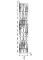
以下、具体的に説明する。ここでは、Nrb=14、Nd=2、所定数を2とする。また、各RBによりLch#1〜#14またはDch#1〜#14が構成される。また、Nd=2、所定数が2であるので、ブロックインタリーバの列数は4となる。そこで、ブロックインタリーバのサイズは、列数を4に固定し、行数をceil(Nrb/列数)により算出する。ここで、演算子ceil(x)はxを超える最小の整数を表す。すなわち、ここでは、図25に示すように、4(=ceil(14/4))行×4列のブロックインタリーバを用いる。 This will be specifically described below. Here, Nrb = 14, Nd = 2, and the predetermined number is 2. Each RB constitutes
ここで、図25に示すブロックインタリーバのサイズが16(=4行×4列)であるのに対し、ブロックインタリーバに入力されるDchのチャネル番号k=1,2,…,Nrbは、14個である。すなわち、Dchのチャネル数がブロックインタリーバのサイズより少なく、Dchのチャネル数(14個)はブロックインタリーバの列数(4列)で割り切ることができない。 Here, the size of the block interleaver shown in FIG. 25 is 16 (= 4 rows × 4 columns), whereas the channel numbers k = 1, 2,..., Nrb of Dch input to the block interleaver are 14 pieces. It is. That is, the number of Dch channels is smaller than the size of the block interleaver, and the number of Dch channels (14) cannot be divided by the number of block interleaver columns (4 columns).
そこで、本実施の形態では、ブロックインタリーバに対して、ブロックインタリーバのサイズとDchのチャネル数との差の個数だけNullが挿入される。すなわち、図25に示すように、2(=16−14)個のNullがブロックインタリーバに挿入される。具体的には、2個のNullは、ブロックインタリーバの最後の行である4行目に均等に挿入される。換言すると、2個のNullは、ブロックインタリーバの最後の行である4行目に1つおきに挿入される。すなわち、図25に示すように、4行×4列のブロックインタリーバのうち、4行目の2列目および4列目にNullが挿入される。よって、図25に示すように、最後の行である4行目の2列目および4列目のNull以外の位置にDchのチャネル番号k=1〜14が列方向に入力される。すなわち、ブロックインタリーバの最後の行では、Dchのチャネル番号k=13,14が、列方向に1つおきに入力される。なお、Nd=2の場合、2個の互いに異なるDchが2個のRBの各サブブロックに分散配置されるため、Dchのチャネル総数は偶数になる。このため、列数が4であるブロックインタリーバに挿入されるNullの数は、0個または2個の場合のみが起こり得る。 Therefore, in the present embodiment, Nulls are inserted into the block interleaver by the number of differences between the size of the block interleaver and the number of Dch channels. That is, as shown in FIG. 25, 2 (= 16-14) Nulls are inserted into the block interleaver. Specifically, two Nulls are evenly inserted in the fourth row, which is the last row of the block interleaver. In other words, two Nulls are inserted every other row in the fourth row, which is the last row of the block interleaver. That is, as shown in FIG. 25, Null is inserted into the second and fourth columns of the fourth row in the 4 × 4 block interleaver. Therefore, as shown in FIG. 25, Dch channel numbers k = 1 to 14 are input in the column direction at positions other than the second and fourth columns of the fourth row, which is the last row. That is, in the last row of the block interleaver, Dch channel numbers k = 13 and 14 are input every other column direction. In the case of Nd = 2, two different Dch are distributed in each sub-block of two RBs, so the total number of Dch channels is an even number. For this reason, the number of Nulls inserted into a block interleaver with 4 columns can only be 0 or 2.
ここでは、Nrb=14、Nd=2であるので、floor(Nrb/Nd)=7となる。また、j(k)は、図25に示すように、4行×4列のブロックインタリーバにより与えられる。ただし、図25に示すブロックインタリーバに挿入されたNullは、ブロックインタリーバ出力時には読み飛ばされ、j(k)として出力されない。すなわち、図25に示すように、k=1,2,3,4,5,6,7,8,9,10,11,12,13,14に対して、j(k)=1,5,9,13,2,6,10,3,7,11,14,4,8,12が得られる。よって、k≦7の場合、Dch#(j(k))は、周波数領域で7(=floor(14/2))RBの間隔で離れたRB#(k)およびRB#(k+7)の2RBに分散配置される。また、k>7の場合、Dch#(j(k))は、周波数領域で7RBの間隔で離れたRB#(k)およびRB#(k−7)の2RBに分散配置される。 Here, since Nrb = 14 and Nd = 2, floor (Nrb / Nd) = 7. Further, j (k) is given by a 4 × 4 block interleaver as shown in FIG. However, Null inserted in the block interleaver shown in FIG. 25 is skipped when the block interleaver is output, and is not output as j (k). That is, as shown in FIG. 25, for k = 1, 2, 3, 4, 5, 6, 7, 8, 9, 10, 11, 12, 13, 14, j (k) = 1, 5 , 9, 13, 2, 6, 10, 3, 7, 11, 14, 4, 8, 12 are obtained. Therefore, when k ≦ 7, Dch # (j (k)) is 2RB of RB # (k) and RB # (k + 7) separated by an interval of 7 (= floor (14/2)) RB in the frequency domain. Distributed. When k> 7, Dch # (j (k)) is distributed and arranged in 2 RBs of RB # (k) and RB # (k−7) that are separated by an interval of 7 RBs in the frequency domain.
具体的には、k=1の場合にはj(k)=1であるので、Dch#1はRB#1およびRB#8(=1+7)に分散配置され、k=2の場合にはj(k)=5であるので、Dch#5はRB#2およびRB#9(=2+7)に分散配置される。k=3〜7の場合についても同様である。 Specifically, since j (k) = 1 when k = 1,
また、k=8の場合にはj(k)=3であるので、Dch#3はRB#8およびRB#1(=8−7)に分散配置され、k=9の場合にはj(k)=7であるので、Dch#7はRB#9およびRB#2(=9−7)に分散配置される。k=10〜14の場合についても同様である。 Since j (k) = 3 when k = 8,
これにより、図26に示すように、Dch#1,#3がRB#1(RB#8)に配置され、Dch#5,#7がRB#2(RB#9)に配置され、Dch#9,#11がRB#3(RB#10)に配置され、Dch#13,#14がRB#4(RB#11)に配置され、Dch#2,#4がRB#5(RB#12)に配置され、Dch#6,#8がRB#6(RB#13)に配置され、Dch#10,#12がRB#7(RB#14)に配置される。すなわち、図26に示すように、全てのRBでは、所定数2以内のチャネル番号の2個のDchがそれぞれ配置される。 Thus, as shown in FIG. 26,
図24に示すブロックインタリーバと同様、図25に示すブロックインタリーバ出力のうち前半部分(すなわち、ブロックインタリーバの1,2列目)のチャネル番号j(k)=1,5,9,13,2,6,10と、ブロックインタリーバ出力のうち後半部分(すなわち、ブロックインタリーバの3,4列目)のチャネル番号j(k)=3,7,11,14,4,8,12とが、図26に示すように、同一RBに配置される。ここで、図25に示すブロックインタリーバに挿入された2個のNullは、ブロックインタリーバの1,2列目からなる4行×2列の前半部分、および、ブロックインタリーバの3,4列目からなる4行×2列の後半部分に、それぞれ1個ずつ挿入される。さらに、2個のNullが挿入される位置は、ブロックインタリーバ出力の前半部分の4行目の2列目(図25に示すブロックインタリーバの4行目の2列目)、および、ブロックインタリーバ出力の後半部分の4行目の2列目(図25に示すブロックインタリーバの4行目の4列目)である。つまり、図25に示すブロックインタリーバの前半部分および後半部分において、2個のNullは同一位置に挿入される。つまり、2個のNullは、ブロックインタリーバにおいて、同一RBに配置され得る位置に挿入される。このため、Nullが挿入された位置以外の位置に入力されたDchのチャネル番号においても、所定数(列数/Nd)以内のチャネル番号が同一RBに配置されるという対応関係が保たれる。よって、ブロックインタリーバのサイズに対してDchのチャネル数が少ない場合でも、所定数(列数/Nd)以内のチャネル番号のDchが同一RBに配置される。 Similarly to the block interleaver shown in FIG. 24, the channel number j (k) = 1, 5, 9, 13, 2, 2 of the first half of the block interleaver output shown in FIG. 25 (that is, the first and second columns of the block interleaver). 26 and the channel number j (k) = 3, 7, 11, 14, 4, 8, 12 of the latter half of the block interleaver output (that is, the third and fourth columns of the block interleaver) are shown in FIG. As shown in FIG. Here, the two Nulls inserted in the block interleaver shown in FIG. 25 consist of the first half of 4 rows × 2 columns consisting of the first and second columns of the block interleaver, and the third and fourth columns of the block interleaver. One each is inserted into the latter half of 4 rows × 2 columns. Furthermore, the positions at which two Nulls are inserted are the second column of the fourth row in the first half of the block interleaver output (the second column of the fourth row of the block interleaver shown in FIG. 25), and the block interleaver output This is the second column of the fourth row in the second half (the fourth column of the fourth row of the block interleaver shown in FIG. 25). That is, two nulls are inserted at the same position in the first half and the second half of the block interleaver shown in FIG. That is, two Nulls are inserted at positions that can be arranged in the same RB in the block interleaver. For this reason, the correspondence relationship that channel numbers within a predetermined number (number of columns / Nd) are arranged in the same RB is maintained even in the channel numbers of Dch inputted at positions other than the position where Null is inserted. Therefore, even when the number of Dch channels is smaller than the size of the block interleaver, Dchs with channel numbers within a predetermined number (number of columns / Nd) are arranged in the same RB.
次に、図25に示すブロックインタリーバの入出力処理の流れについて図27を用いて説明する。ここでは、ブロックインタリーバの列数を4に固定する。 Next, the flow of input / output processing of the block interleaver shown in FIG. 25 will be described with reference to FIG. Here, the number of columns of the block interleaver is fixed to 4.
ステップ(以下、STという)101では、ブロックインタリーバのサイズがceil(Nrb/4)行×4列に決定される。 In step (hereinafter referred to as ST) 101, the size of the block interleaver is determined to be ceil (Nrb / 4) rows × 4 columns.
ST102では、RB数Nrbが4で割り切れるかどうかが判定される。ここで、図27に示す演算子modは、modulo演算を示す。 In ST102, it is determined whether or not the number of RBs Nrb is divisible by 4. Here, an operator mod shown in FIG. 27 indicates a modulo operation.
ST102において、RB数Nrbが4で割り切れる場合(ST102:Yes)、ST103では、Dchのチャネル番号(k)がブロックインタリーバに対して列方向に連続して書き込まれる。 In ST102, when the number of RBs Nrb is divisible by 4 (ST102: Yes), in ST103, the Dch channel number (k) is continuously written in the column direction to the block interleaver.
ST104では、Dchのチャネル番号(j(k))が、ブロックインタリーバから行方向に連続して読み出される。 In ST104, the Dch channel number (j (k)) is continuously read in the row direction from the block interleaver.
一方、ST102において、RB数Nrbが4で割り切れない場合(ST102:No)、ST105では、ST103と同様にして、Dchのチャネル番号(k)がブロックインタリーバに対して列方向に連続して書き込まれる。ただし、ブロックインタリーバの最後の行(例えば、図25に示す4行目)では、1列おきにNullが挿入される。 On the other hand, in ST102, when the number of RBs Nrb is not divisible by 4 (ST102: No), in ST105, the channel number (k) of Dch is continuously written in the column direction to the block interleaver, as in ST103. . However, Null is inserted every other column in the last row of the block interleaver (for example, the fourth row shown in FIG. 25).
ST106では、ST104と同様にして、Dchのチャネル番号(j(k))が、ブロックインタリーバから行方向に連続して読み出される。ただし、ブロックインタリーバ書き込み時に挿入されたNull(例えば、図25に示す4行目の2列目および4列目)を読み飛ばしたチャネル番号(j(k))が読み出される。 In ST106, as in ST104, the Dch channel number (j (k)) is continuously read in the row direction from the block interleaver. However, the channel number (j (k)) obtained by skipping Null (for example, the second and fourth columns of the fourth row shown in FIG. 25) inserted at the time of writing the block interleaver is read.
このようにして、Dchのチャネル数がブロックインタリーバの列数で割り切れない場合、ブロックインタリーバ入力時には、Nullを挿入してDchのチャネル番号kを書き込み、ブロックインタリーバ出力時には、Nullを読み飛ばしてDchのチャネル番号j(k)を読み出す。これにより、Dchのチャネル数がブロックインタリーバの列数で割り切れない場合でも、実施の形態1の配置方法3と同様、連続するチャネル番号のDchを異なるRBに配置し、かつ、1RBに所定数以内のチャネル番号のDchを配置することができる。 In this way, if the number of Dch channels is not divisible by the number of block interleaver columns, Null is inserted and the Dch channel number k is written when the block interleaver is input, and Null is skipped when the block interleaver is output and the Dch Read channel number j (k). As a result, even when the number of Dch channels is not divisible by the number of columns in the block interleaver, Dch with consecutive channel numbers are arranged in different RBs and within a predetermined number within 1 RB, as in the
基地局100および移動局200では、上述したDchのチャネル配置方法により、連続するチャネル番号のDchが異なるRBに配置され、かつ、1RBに所定数以内のチャネル番号のDchが配置された、RBとDchとが予め対応付けられる。つまり、基地局100の割当部103(図1)および移動局200のデマッピング部207(図2)は、RBとDchとの対応付けである、図26に示すDchの配置パターンを保持する。 In the
そして、基地局100の割当部103は、実施の形態1の配置方法3と同様にして、図26に示すDchの配置パターンに従って、DchデータシンボルをRBに割り当てる。一方、移動局200のデマッピング部207は、割当部103と同様、図26に示すDchの配置パターンに従って、複数のRBから自局宛てのDchデータシンボルを抽出する。 Then,
これにより、実施の形態1の配置方法3と同様、1つの移動局のDchデータシンボルに対して使用するDchの数が少ない場合、RB内で割り当てられたサブブロック以外のサブブロックが使用されない可能性があるものの周波数ダイバーシチ効果を優先して得ることができる。また、1つの移動局のDchデータシンボルに対して使用するDchの数が多い場合、つまり、割り当てられるRBが多い場合でも、周波数ダイバーシチ効果を得つつ、RB内のすべてのサブブロックを使用することができる。 As a result, similar to the
このようにして、本実施の形態では、Dchのチャネル番号を、インタリーブすることで、連続するチャネル番号のDchを異なるRBに配置し、1RBに所定数以内のチャネル番号のDchを配置する。これにより、実施の形態1の配置方法3と同様、1つの移動局のDchデータシンボルに使用されるDchの数が少ない場合には、周波数ダイバーシチ効果を向上させることができる。また、1つの移動局のDchデータシンボルに使用されるDchの数が多い場合でも、通信リソースの利用効率を低下させることなく、周波数ダイバーシチ効果を向上させることができる。 In this manner, in this embodiment, Dch channel numbers are interleaved so that Dchs of consecutive channel numbers are arranged in different RBs, and Dchs of channel numbers within a predetermined number are arranged in one RB. As a result, similar to the
また、本実施の形態では、Dchのチャネル数とブロックインタリーバのサイズとが一致せず、Dchのチャネル数がブロックインタリーバの列数で割り切れない場合でも、ブロックインタリーバにNullを挿入することにより、連続するチャネル番号のDchを異なるRBに配置し、1RBに所定数以内のチャネル番号のDchを配置することができる。また、本実施の形態によれば、あらゆるDchのチャネル数のシステムに対しても、ブロックインタリーバにNullを挿入するだけで、同一のブロックインタリーバ構成、つまり、同一のチャネル配置方法を適用することが可能となる。 Also, in this embodiment, even if the number of Dch channels does not match the size of the block interleaver, and the number of Dch channels is not divisible by the number of columns of the block interleaver, the Null is inserted into the block interleaver to Dch of channel numbers to be assigned can be arranged in different RBs, and Dch of channel numbers within a predetermined number can be arranged in 1 RB. Also, according to the present embodiment, the same block interleaver configuration, that is, the same channel arrangement method can be applied to a system having any number of Dch channels by simply inserting a null into the block interleaver. It becomes possible.
なお、本実施の形態では、RB数Nrbが偶数(例えば、Nrb=14)の場合について説明した。しかし、RB数Nrbが奇数の場合でも、Nrb以下の最大の偶数をNrbに置き換えて適用することにより、本実施の形態と同様の効果を得ることができる。 In the present embodiment, the case where the number of RBs Nrb is an even number (for example, Nrb = 14) has been described. However, even when the number of RBs Nrb is an odd number, the same effect as in the present embodiment can be obtained by replacing the maximum even number equal to or less than Nrb with Nrb.
また、本実施の形態では、2個のNullを挿入する位置が、ブロックインタリーバ出力の前半部分の4行目の2列目(図25に示すブロックインタリーバの4行目の2列目)、および、ブロックインタリーバ出力の後半部分の4行目の4列目(図25に示すブロックインタリーバの4行目の4列目)である場合について説明した。しかし、本発明では、2個のNullが挿入される位置は、ブロックインタリーバ出力の前半部分および後半部分において同一位置であればよい。よって、例えば、2個のNullが挿入される位置は、ブロックインタリーバ出力の前半部分の4行目の1列目(図25に示すブロックインタリーバの4行目の1列目)、および、ブロックインタリーバ出力の後半部分の4行目の1列目(図25に示すブロックインタリーバの4行目の3列目)としてもよい。また、2個のNullが挿入される位置は、ブロックインタリーバの最後の行(例えば、図25に示す4行目)に限らず、他の行(例えば、図25に示す1〜3行目)でもよい。 In the present embodiment, the position where two Nulls are inserted is the second column of the fourth row in the first half of the block interleaver output (the second column of the fourth row of the block interleaver shown in FIG. 25), and The case of the fourth column of the fourth row (the fourth column of the fourth row of the block interleaver shown in FIG. 25) in the latter half of the block interleaver output has been described. However, in the present invention, the positions where two Nulls are inserted may be the same position in the first half and the second half of the block interleaver output. Thus, for example, the positions at which two Nulls are inserted are the first column of the fourth row in the first half of the block interleaver output (the first column of the fourth row of the block interleaver shown in FIG. 25), and the block interleaver. It may be the first column of the fourth row in the latter half of the output (the third column of the fourth row of the block interleaver shown in FIG. 25). Further, the position where two Nulls are inserted is not limited to the last row of the block interleaver (for example, the fourth row shown in FIG. 25), but other rows (for example, the first to third rows shown in FIG. 25). But you can.
以上、本発明の各実施の形態について説明した。 The embodiments of the present invention have been described above.
なお、上記実施の形態では、DchをRBに配置するチャネル配置方法は、システム帯域幅によって決定される総RB数(Nrb)に依存する。そこで、基地局および移動局は、システム帯域幅毎にDchチャネル番号とRB番号との対応表(例えば、図4,図8,図11,図15,図26等)を保持しておき、Dchデータシンボル割当の際に、Dchデータシンボルを割り当てるシステム帯域幅に対応する対応表を参照するようにしてもよい。 In the above embodiment, the channel allocation method for allocating Dch to RB depends on the total number of RBs (Nrb) determined by the system bandwidth. Therefore, the base station and the mobile station maintain a correspondence table (for example, FIG. 4, FIG. 8, FIG. 11, FIG. 15, FIG. 26, etc.) of Dch channel numbers and RB numbers for each system bandwidth. When assigning data symbols, a correspondence table corresponding to the system bandwidth to which Dch data symbols are assigned may be referred to.
また、上記実施の形態では、基地局が受信する信号(すなわち、移動局が上り回線で送信する信号)はOFDM方式で伝送されるものとして説明したが、この信号は、例えばシングルキャリア方式やCDMA方式等、OFDM方式以外の伝送方式で伝送されてもよい。 In the above-described embodiment, the signal received by the base station (that is, the signal transmitted by the mobile station on the uplink) has been described as being transmitted by the OFDM method. However, this signal is, for example, a single carrier method or CDMA. It may be transmitted by a transmission method other than the OFDM method such as a method.
また、上記実施の形態では、RBは、OFDMシンボルを構成する複数のサブキャリアから構成される場合について説明したが、これには限られず、連続する周波数で構成されるブロックであれば良い。 Moreover, although the case where RB was comprised from the some subcarrier which comprises an OFDM symbol was demonstrated in the said embodiment, it is not restricted to this, What is necessary is just a block comprised by a continuous frequency.
また、上記実施の形態では、RBは周波数領域で連続して構成される場合について説明したが、RBは時間領域に連続して構成されてもよい。 Moreover, although the case where RB was comprised continuously in the frequency domain was demonstrated in the said embodiment, RB may be comprised continuously in a time domain.
また、上記実施の形態では、基地局が送信する信号(すなわち、基地局が下り回線で送信する信号)に対して適用する場合について説明したが、本発明は、基地局が受信する信号(すなわち、移動局が上り回線で送信する信号)に対して適用してもよい。この場合、基地局が上り回線の信号に対するRB割当などの適応制御を行う。 In the above embodiment, the case where the present invention is applied to a signal transmitted by the base station (that is, a signal transmitted by the base station in the downlink) has been described. The signal may be applied to a signal transmitted by a mobile station on an uplink. In this case, the base station performs adaptive control such as RB allocation for uplink signals.
また、上記実施の形態では、Lchに対してのみ適応変調を行ったが、Dchに対しても同様に適応変調を行ってもよい。このとき、基地局では、各移動局から報告される全帯域の平均受信品質情報に基づいてDchデータに対する適応変調を行ってもよい。 In the above embodiment, adaptive modulation is performed only for Lch, but adaptive modulation may be performed for Dch as well. At this time, the base station may perform adaptive modulation on the Dch data based on the average reception quality information of all bands reported from each mobile station.
また、上記実施の形態では、Dchに使用するRBは時間領域で複数のサブブロックに分割されるものとして説明したが、Dchに使用するRBは、周波数領域で複数のサブブロックに分割されてもよく、時間領域および周波数領域で複数のサブブロックに分割されてもよい。つまり、1RBにおいて、複数のDchが周波数多重されてもよく、時間多重および周波数多重されてもよい。 In the above embodiment, the RB used for Dch has been described as being divided into a plurality of subblocks in the time domain. However, the RB used for Dch may be divided into a plurality of subblocks in the frequency domain. It may be divided into a plurality of sub-blocks in the time domain and the frequency domain. That is, in 1 RB, a plurality of Dch may be frequency-multiplexed, or time-multiplexed and frequency-multiplexed.
また、本実施の形態では、1移動局にチャネル番号が連続する異なる複数のDchを割り当てる場合、先頭のチャネル番号および末尾のチャネル番号のみを基地局から移動局に通知する場合について説明したが、例えば、先頭のチャネル番号およびチャネル数を基地局から移動局に通知してもよい。 Further, in this embodiment, when a plurality of different Dch having consecutive channel numbers are allocated to one mobile station, a case has been described in which only the first channel number and the last channel number are notified from the base station to the mobile station. For example, the head channel number and the number of channels may be notified from the base station to the mobile station.
また、本実施の形態では、1Dchを周波数領域で等間隔に分散配置されたRBに配置する場合について説明したが、1Dchを周波数領域で等間隔に分散配置されたRBに配置しなくてもよい。 Further, in the present embodiment, a case has been described in which 1Dch is arranged in RBs that are distributed at equal intervals in the frequency domain, but 1Dch may not be arranged in RBs that are distributed in equal intervals in the frequency domain. .
また、上記実施の形態では、周波数ダイバーシチ送信を行うためのチャネルにDchを使用したが、使用するチャネルはDchに限らず、周波数領域で、複数のRBまたは、複数のサブキャリアに分散配置され、周波数ダイバーシチ効果を得ることができるチャネルであればよい。また、周波数スケジューリング送信を行うためのチャネルにLchを使用したが、使用するチャネルはLchに限らず、マルチユーザダイバーシチ効果を得ることができるチャネルであればよい。 In the above embodiment, Dch is used as a channel for performing frequency diversity transmission. However, the channel to be used is not limited to Dch, and is distributed and arranged in a plurality of RBs or a plurality of subcarriers in the frequency domain. Any channel that can obtain a frequency diversity effect may be used. In addition, although Lch is used as a channel for performing frequency scheduling transmission, the channel to be used is not limited to Lch, and any channel that can obtain a multiuser diversity effect may be used.
また、DchはDVRB(Distributed Virtual Resource Block)、LchはLVRB(Localized Virtual Resource Block)と称されることもある。また、Dchに使用されるRBはDRBまたはDPRB(Distributed Physical Resource Block)と称されることもあり、Lchに使用されるRBはLRBまたはLPRB(Localized Physical Resource Block)と称されることもある。 Further, Dch may be referred to as DVRB (Distributed Virtual Resource Block), and Lch may be referred to as LVRB (Localized Virtual Resource Block). An RB used for Dch may be referred to as DRB or DPRB (Distributed Physical Resource Block), and an RB used for Lch may be referred to as LRB or LPRB (Localized Physical Resource Block).
また、移動局はUE、基地局装置はNode B、サブキャリアはトーンと称されることもある。また、RBは、サブチャネル、サブキャリアブロック、サブキャリアグループ、サブバンド、または、チャンクと称されることもある。また、CPは、ガードインターバル(Guard Interval:GI)と称されることもある。また、サブフレームはスロット、フレームと称されることもある。 Also, the mobile station may be referred to as UE, the base station apparatus as Node B, and the subcarrier as tone. An RB may also be referred to as a subchannel, a subcarrier block, a subcarrier group, a subband, or a chunk. The CP may also be referred to as a guard interval (GI). A subframe may also be referred to as a slot or a frame.
また、上記実施の形態では、本発明をハードウェアで構成する場合を例にとって説明したが、本発明はソフトウェアで実現することも可能である。 Further, although cases have been described with the above embodiment as examples where the present invention is configured by hardware, the present invention can also be realized by software.
また、上記実施の形態の説明に用いた各機能ブロックは、典型的には集積回路であるLSIとして実現される。これらは個別に1チップ化されてもよいし、一部または全てを含むように1チップ化されてもよい。ここでは、LSIとしたが、集積度の違いにより、IC、システムLSI、スーパーLSI、ウルトラLSIと呼称されることもある。 Each functional block used in the description of the above embodiment is typically realized as an LSI which is an integrated circuit. These may be individually made into one chip, or may be made into one chip so as to include a part or all of them. The name used here is LSI, but it may also be called IC, system LSI, super LSI, or ultra LSI depending on the degree of integration.
また、集積回路化の手法はLSIに限るものではなく、専用回路または汎用プロセッサで実現してもよい。LSI製造後に、プログラムすることが可能なFPGA(Field Programmable Gate Array)や、LSI内部の回路セルの接続や設定を再構成可能なリコンフィギュラブル・プロセッサを利用してもよい。 Further, the method of circuit integration is not limited to LSI's, and implementation using dedicated circuitry or general purpose processors is also possible. An FPGA (Field Programmable Gate Array) that can be programmed after manufacturing the LSI, or a reconfigurable processor that can reconfigure the connection and setting of circuit cells inside the LSI may be used.
さらには、半導体技術の進歩または派生する別技術によりLSIに置き換わる集積回路化の技術が登場すれば、当然、その技術を用いて機能ブロックの集積化を行ってもよい。バイオ技術の適用等が可能性としてありえる。 Furthermore, if integrated circuit technology comes out to replace LSI's as a result of the advancement of semiconductor technology or a derivative other technology, it is naturally also possible to carry out function block integration using this technology. Biotechnology can be applied.
2007年6月19日出願の特願2007−161958、2007年8月14日出願の特願2007−211545および2008年3月6日出願の特願2008−056561の日本出願に含まれる明細書、図面および要約書の開示内容は、すべて本願に援用される。 Japanese Patent Application No. 2007-161958 filed on June 19, 2007, Japanese Patent Application No. 2007-212545 filed on August 14, 2007, and Japanese Patent Application No. 2008-056561 filed on March 6, 2008, The entire disclosure of the drawings and abstract is incorporated herein by reference.
本発明は、移動体通信システム等に適用することができる。 The present invention can be applied to a mobile communication system or the like.
Claims (24)
Translated fromJapanese前記フィジカル・リソース・ブロックを用いて、データを送信する送信処理と、
を制御し、
前記配置処理は、ブロックインタリーバのサイズと前記ディストリビューテッド・バーチャル・リソース・ブロックの総数との差の個数のNullが、前記ブロックインタリーバの前半の2列と後半の2列において、同一位置に挿入された4列のブロックインタリーバであって、前記ディストリビューテッド・バーチャル・リソース・ブロックの番号を、列方向に書き込み、行方向に読み出すブロックインタリーバを用いて、前記ブロックインタリーバの前半の2列と後半の2列において、同一位置に書き込まれた番号の2つの前記ディストリビューテッド・バーチャル・リソース・ブロックを、一サブフレーム内の同一周波数における前記フィジカル・リソース・ブロックに配置し、
周波数領域で隣り合うフィジカル・リソース・ブロックに、番号が連続しない前記ディストリビューテッド・バーチャル・リソース・ブロックを配置する、
集積回路。An arrangement in which consecutive distributed virtual resource block numbers are interleaved, and the distributed virtual resource blocks interleaved with the numbers are arranged in physical resource blocks composed of a plurality of subcarriers. Processing,
A transmission process of transmitting data using the physical resource block;
Control
In the arrangement process, Nulls corresponding to the difference between the size of the block interleaver and the total number of the distributed virtual resource blocks are inserted at the same position in the first two columns and the second half of the block interleaver. A block interleaver of four columns, wherein the distributed virtual resource block numbers are written in the column direction and read in the row direction, and the first two columns and the second half of the block interleaver are used. in column, two of the Distributed Virtual resource blocks written in the same position number,arranged in the physical resource blocks in the same frequency within a subframe,
Arranging the distributed virtual resource blocks whose numbers are not consecutive in physical resource blocks adjacent in the frequency domain;
Integrated circuit.
請求項1に記載の集積回路。In the arrangement process, the total number of the distributed virtual resource blocks is Nrb, and a block interleaver of 4 columns × ceil (Nrb / 4) rows is used.
The integrated circuit according to claim 1.
請求項1又は2のいずれかに記載の集積回路。The Null is inserted every other column in the same row of the block interleaver.
The integrated circuit according to claim 1.
請求項1から3のいずれかに記載の集積回路。The Null is inserted into a predetermined row in the second and fourth columns of the block interleaver.
The integrated circuit according to claim 1.
請求項1から4のいずれかに記載の集積回路。The Null is inserted in the last row of the second and fourth columns of the block interleaver.
The integrated circuit according to claim 1.
請求項1から5のいずれかに記載の集積回路。The placement process places the distributed virtual resource block in the physical resource block so that the consecutive number of distributed virtual resource blocks are distributed in the frequency domain.
An integrated circuit according to claim 1.
請求項1から6のいずれかに記載の集積回路。Further controlling an assignment process of assigning consecutive numbers of the distributed virtual resource blocks to one mobile station device;
The integrated circuit according to claim 1.
請求項7に記載の集積回路。The transmission processing transmits allocation information indicating the distributed virtual resource block of the allocated consecutive numbers to the mobile station device.
The integrated circuit according to claim 7.
請求項7又は8に記載の集積回路。The transmission process transmits, to the mobile station apparatus, allocation information based on an initial number and a number regarding the distributed virtual resource block of consecutive numbers allocated.
The integrated circuit according to claim 7 or 8.
請求項1から9のいずれかに記載の集積回路。The placement processing is performed by changing the distributed virtual resource block to the physical resource block so that the distributed virtual resource blocks with the same number are distributed in the frequency domain and are different in the time domain. Deploy,
The integrated circuit according to claim 1.
請求項1から10のいずれかに記載の集積回路。The difference between the numbers of the two distributed virtual resource blocks arranged in one subframe is within a predetermined number.
The integrated circuit according to claim 1.
請求項1から11のいずれかに記載の集積回路。The difference between the numbers of the two distributed virtual resource blocks arranged in one subframe is 2.
The integrated circuit according to claim 1.
請求項1から12のいずれかに記載の集積回路。The total number of the distributed virtual resource blocks is set to Nrb, and the placement processing is performed in such a manner that the distributed virtual resource blocks having the same number are separated from each other in the frequency domain by Nrb / 2 intervals. Place it in a resource block,
The integrated circuit according to claim 1.
前記割当情報に基づいて、前記データを復号する復号処理と、
を制御し、
前記ディストリビューテッド・バーチャル・リソース・ブロックの番号は、ブロックインタリーバのサイズと前記ディストリビューテッド・バーチャル・リソース・ブロックの総数との差の個数のNullが、前記ブロックインタリーバの前半の2列と後半の2列において、同一位置に挿入された4列のブロックインタリーバによって、列方向に書き込まれ、行方向に読み出されて、
前記ブロックインタリーバの前半の2列と後半の2列において、同一位置に書き込まれた番号の2つの前記ディストリビューテッド・バーチャル・リソース・ブロックが、一サブフレーム内の同一周波数における前記フィジカル・リソース・ブロックに配置され、
周波数領域で隣り合うフィジカル・リソース・ブロックに、番号が連続しない前記ディストリビューテッド・バーチャル・リソース・ブロックが配置されている、
集積回路。Sequential numbers of distributed virtual resource blocks are allocated to the mobile station apparatus and data transmitted using physical resource blocks composed of a plurality of subcarriers arranged by interleaving the numbers. Receiving processing for receiving the allocation information indicating the distributed virtual resource blocks of consecutive numbers;
A decoding process for decoding the data based on the allocation information;
Control
The number of the distributed virtual resource block is the difference between the size of the block interleaver and the total number of the distributed virtual resource blocks. In a column, a block interleaver of 4 columns inserted at the same position writes in the column direction and reads in the row direction,
In the first two columns and the latter two columns of the block interleaver, the two distributed virtual resource blocks with numbers written at the same position are the physical resource blocks at the same frequency in one subframe.It is locatedin,
The distributed virtual resource blocks whose numbers are not consecutive are arranged in physical resource blocks adjacent in the frequency domain,
Integrated circuit.
請求項14に記載の集積回路。The Null is inserted into a predetermined row in the second and fourth columns of the block interleaver.
The integrated circuit according to claim 14.
請求項14又は15に記載の集積回路。The Null is inserted in the last row of the second and fourth columns of the block interleaver.
The integrated circuit according to claim 14 or 15.
請求項14から16のいずれかに記載の集積回路。The consecutively numbered distributed virtual resource blocks are arranged in the physical resource blocks so as to be distributed in the frequency domain.
The integrated circuit according to claim 14.
請求項14から17のいずれかに記載の集積回路。The reception process receives the allocation information based on an initial number and number of the distributed virtual resource blocks of consecutive numbers allocated.
The integrated circuit according to claim 14.
請求項14から18のいずれかに記載の集積回路。The distributed virtual resource blocks with the same number are arranged in the physical resource blocks so that they are distributed in the frequency domain and different in the time domain.
The integrated circuit according to claim 14.
請求項14から19のいずれかに記載の集積回路。The difference between the numbers of the two distributed virtual resource blocks arranged in one subframe is within a predetermined number.
The integrated circuit according to claim 14.
請求項14から20のいずれかに記載の集積回路。The difference between the numbers of the two distributed virtual resource blocks arranged in one subframe is 2.
The integrated circuit according to claim 14.
請求項14から21のいずれかに記載の集積回路。The total number of the distributed virtual resource blocks is Nrb, and the distributed virtual resource blocks having the same number are arranged in the physical resource blocks separated by Nrb / 2 intervals in the frequency domain. Being
The integrated circuit according to claim 14.
前記フィジカル・リソース・ブロックを用いて、データを送信する送信手段と、Transmission means for transmitting data using the physical resource block;
を有し、Have
前記配置手段は、The arrangement means includes
ブロックインタリーバのサイズと前記ディストリビューテッド・バーチャル・リソース・ブロックの総数との差の個数のNullが、前記ブロックインタリーバの前半の2列と後半の2列において、同一位置に挿入された4列のブロックインタリーバであって、前記ディストリビューテッド・バーチャル・リソース・ブロックの番号を、列方向に書き込み、行方向に読み出すブロックインタリーバを用いて、前記ブロックインタリーバの前半の2列と後半の2列において、同一位置に書き込まれた番号の2つの前記ディストリビューテッド・バーチャル・リソース・ブロックを、一サブフレーム内の同一周波数における前記フィジカル・リソース・ブロックに配置し、Null of the number of differences between the size of the block interleaver and the total number of the distributed virtual resource blocks is inserted in the same position in the first two columns and the second two columns of the block interleaver. An interleaver that uses the block interleaver that writes the distributed virtual resource block number in the column direction and reads the row direction in the same position in the first two columns and the second two columns of the block interleaver. Two distributed virtual resource blocks with the numbers written in the physical resource blocks at the same frequency in one subframe,
周波数領域で隣り合うフィジカル・リソース・ブロックに、番号が連続しない前記ディストリビューテッド・バーチャル・リソース・ブロックを配置する、Arranging the distributed virtual resource blocks whose numbers are not consecutive in physical resource blocks adjacent in the frequency domain;
基地局装置。Base station device.
前記割当情報に基づいて、前記データを復号する復号手段と、Decoding means for decoding the data based on the allocation information;
を有し、Have
前記ディストリビューテッド・バーチャル・リソース・ブロックの番号は、ブロックインタリーバのサイズと前記ディストリビューテッド・バーチャル・リソース・ブロックの総数との差の個数のNullが、前記ブロックインタリーバの前半の2列と後半の2列において、同一位置に挿入された4列のブロックインタリーバによって、列方向に書き込まれ、行方向に読み出されて、The number of the distributed virtual resource block is the difference between the size of the block interleaver and the total number of the distributed virtual resource blocks. In a column, a block interleaver of 4 columns inserted at the same position writes in the column direction and reads in the row direction,
前記ブロックインタリーバの前半の2列と後半の2列において、同一位置に書き込まれた番号の2つの前記ディストリビューテッド・バーチャル・リソース・ブロックが、一サブフレーム内の同一周波数における前記フィジカル・リソース・ブロックに配置され、In the first two columns and the latter two columns of the block interleaver, the two distributed virtual resource blocks with numbers written at the same position are the physical resource blocks at the same frequency within one subframe. Placed in
周波数領域で隣り合うフィジカル・リソース・ブロックに、番号が連続しない前記ディストリビューテッド・バーチャル・リソース・ブロックが配置されている、The distributed virtual resource blocks whose numbers are not consecutive are arranged in physical resource blocks adjacent in the frequency domain,
移動局装置。Mobile station device.
Priority Applications (1)
| Application Number | Priority Date | Filing Date | Title |
|---|---|---|---|
| JP2012144170AJP5425268B2 (en) | 2007-06-19 | 2012-06-27 | Integrated circuit |
Applications Claiming Priority (7)
| Application Number | Priority Date | Filing Date | Title |
|---|---|---|---|
| JP2007161958 | 2007-06-19 | ||
| JP2007161958 | 2007-06-19 | ||
| JP2007211545 | 2007-08-14 | ||
| JP2007211545 | 2007-08-14 | ||
| JP2008056561 | 2008-03-06 | ||
| JP2008056561 | 2008-03-06 | ||
| JP2012144170AJP5425268B2 (en) | 2007-06-19 | 2012-06-27 | Integrated circuit |
Related Parent Applications (1)
| Application Number | Title | Priority Date | Filing Date |
|---|---|---|---|
| JP2010139649ADivisionJP5032633B2 (en) | 2007-06-19 | 2010-06-18 | Integrated circuit |
Related Child Applications (1)
| Application Number | Title | Priority Date | Filing Date |
|---|---|---|---|
| JP2013241910ADivisionJP5667689B2 (en) | 2007-06-19 | 2013-11-22 | Transmitting apparatus, data transmitting method and integrated circuit |
Publications (2)
| Publication Number | Publication Date |
|---|---|
| JP2012191668A JP2012191668A (en) | 2012-10-04 |
| JP5425268B2true JP5425268B2 (en) | 2014-02-26 |
Family
ID=40156075
Family Applications (14)
| Application Number | Title | Priority Date | Filing Date |
|---|---|---|---|
| JP2009520321AActiveJP4538535B2 (en) | 2007-06-19 | 2008-06-18 | Base station apparatus, mobile station apparatus, and data transmission method |
| JP2009241728AActiveJP4540741B2 (en) | 2007-06-19 | 2009-10-20 | Base station apparatus, mobile station apparatus, and data transmission method |
| JP2010139649AActiveJP5032633B2 (en) | 2007-06-19 | 2010-06-18 | Integrated circuit |
| JP2012144170AActiveJP5425268B2 (en) | 2007-06-19 | 2012-06-27 | Integrated circuit |
| JP2013241910AActiveJP5667689B2 (en) | 2007-06-19 | 2013-11-22 | Transmitting apparatus, data transmitting method and integrated circuit |
| JP2014250785AActiveJP5878616B2 (en) | 2007-06-19 | 2014-12-11 | Receiving device, receiving method, and integrated circuit |
| JP2016013348AActiveJP6060287B2 (en) | 2007-06-19 | 2016-01-27 | Transmitting apparatus, transmitting method, and integrated circuit |
| JP2016239409AActiveJP6248175B2 (en) | 2007-06-19 | 2016-12-09 | Receiving device, receiving method, and integrated circuit |
| JP2017221971AActiveJP6422559B2 (en) | 2007-06-19 | 2017-11-17 | Transmitting apparatus, transmitting method, and integrated circuit |
| JP2018194208AActiveJP6566336B2 (en) | 2007-06-19 | 2018-10-15 | Receiving device, receiving method, and integrated circuit |
| JP2019131877AActiveJP6744961B2 (en) | 2007-06-19 | 2019-07-17 | Communication system and communication method |
| JP2020129339AActiveJP6956835B2 (en) | 2007-06-19 | 2020-07-30 | Receiver, receiving method and integrated circuit |
| JP2021163464AActiveJP7143497B2 (en) | 2007-06-19 | 2021-10-04 | Transmission device, transmission method and integrated circuit |
| JP2022145282AActiveJP7341300B2 (en) | 2007-06-19 | 2022-09-13 | Communication system and method |
Family Applications Before (3)
| Application Number | Title | Priority Date | Filing Date |
|---|---|---|---|
| JP2009520321AActiveJP4538535B2 (en) | 2007-06-19 | 2008-06-18 | Base station apparatus, mobile station apparatus, and data transmission method |
| JP2009241728AActiveJP4540741B2 (en) | 2007-06-19 | 2009-10-20 | Base station apparatus, mobile station apparatus, and data transmission method |
| JP2010139649AActiveJP5032633B2 (en) | 2007-06-19 | 2010-06-18 | Integrated circuit |
Family Applications After (10)
| Application Number | Title | Priority Date | Filing Date |
|---|---|---|---|
| JP2013241910AActiveJP5667689B2 (en) | 2007-06-19 | 2013-11-22 | Transmitting apparatus, data transmitting method and integrated circuit |
| JP2014250785AActiveJP5878616B2 (en) | 2007-06-19 | 2014-12-11 | Receiving device, receiving method, and integrated circuit |
| JP2016013348AActiveJP6060287B2 (en) | 2007-06-19 | 2016-01-27 | Transmitting apparatus, transmitting method, and integrated circuit |
| JP2016239409AActiveJP6248175B2 (en) | 2007-06-19 | 2016-12-09 | Receiving device, receiving method, and integrated circuit |
| JP2017221971AActiveJP6422559B2 (en) | 2007-06-19 | 2017-11-17 | Transmitting apparatus, transmitting method, and integrated circuit |
| JP2018194208AActiveJP6566336B2 (en) | 2007-06-19 | 2018-10-15 | Receiving device, receiving method, and integrated circuit |
| JP2019131877AActiveJP6744961B2 (en) | 2007-06-19 | 2019-07-17 | Communication system and communication method |
| JP2020129339AActiveJP6956835B2 (en) | 2007-06-19 | 2020-07-30 | Receiver, receiving method and integrated circuit |
| JP2021163464AActiveJP7143497B2 (en) | 2007-06-19 | 2021-10-04 | Transmission device, transmission method and integrated circuit |
| JP2022145282AActiveJP7341300B2 (en) | 2007-06-19 | 2022-09-13 | Communication system and method |
Country Status (10)
| Country | Link |
|---|---|
| US (15) | US7852807B2 (en) |
| EP (4) | EP2698937B1 (en) |
| JP (14) | JP4538535B2 (en) |
| KR (2) | KR101414310B1 (en) |
| CN (3) | CN101682390B (en) |
| BR (1) | BRPI0813126B1 (en) |
| CA (2) | CA2680856C (en) |
| ES (4) | ES2551297T3 (en) |
| RU (2) | RU2480916C2 (en) |
| WO (1) | WO2008155911A1 (en) |
Families Citing this family (27)
| Publication number | Priority date | Publication date | Assignee | Title |
|---|---|---|---|---|
| US8077667B2 (en)* | 2006-04-28 | 2011-12-13 | Panasonic Corporation | Radio communication base station apparatus and radio communication method used for multi-carrier communication |
| EP2698937B1 (en) | 2007-06-19 | 2015-08-19 | Panasonic Intellectual Property Corporation of America | Channel arrangement reception circuit for radio communication |
| TWI505685B (en)* | 2008-01-07 | 2015-10-21 | Optis Cellular Techology Llc | Method for scheduling distributed virtual resource blocks |
| RU2556389C2 (en)* | 2008-01-07 | 2015-07-10 | Оптис Целлулар Течнолоджи,ЛЛС | Method of transmitting/receiving downlink data using resource blocks in wireless mobile communication network system and device therefor |
| KR100925441B1 (en)* | 2008-01-07 | 2009-11-06 | 엘지전자 주식회사 | Distributed Virtual Resource Block Scheduling Method |
| KR100904433B1 (en) | 2008-01-07 | 2009-06-24 | 엘지전자 주식회사 | Distributed Virtual Resource Block Scheduling Method |
| KR100913099B1 (en) | 2008-01-07 | 2009-08-21 | 엘지전자 주식회사 | Distributed Virtual Resource Block Scheduling Method |
| US20110069637A1 (en)* | 2009-09-18 | 2011-03-24 | Futurewei Technologies, Inc. | System and Method for Control Channel Search Space Location Indication for a Relay Backhaul Link |
| CN101754231B (en)* | 2009-12-29 | 2014-03-12 | 中兴通讯股份有限公司 | Wireless channel resource adjusting method and device |
| US9014081B2 (en)* | 2010-04-09 | 2015-04-21 | Futurewei Technologies, Inc. | System and method for transmitting control information |
| EP2605603A4 (en)* | 2010-08-10 | 2017-11-29 | Panasonic Intellectual Property Corporation of America | Base station, relay station, transmission method, and reception method |
| JP5851583B2 (en)* | 2012-02-29 | 2016-02-03 | 京セラ株式会社 | Mobile communication system, mobile communication method, radio base station, and radio terminal |
| US9826439B2 (en) | 2013-09-30 | 2017-11-21 | Elwha Llc | Mobile device sharing facilitation methods and systems operable in network equipment |
| US9813891B2 (en) | 2013-09-30 | 2017-11-07 | Elwha Llc | Mobile device sharing facilitation methods and systems featuring a subset-specific source identification |
| US9740875B2 (en) | 2013-09-30 | 2017-08-22 | Elwha Llc | Mobile device sharing facilitation methods and systems featuring exclusive data presentation |
| US9838536B2 (en)* | 2013-09-30 | 2017-12-05 | Elwha, Llc | Mobile device sharing facilitation methods and systems |
| US9774728B2 (en) | 2013-09-30 | 2017-09-26 | Elwha Llc | Mobile device sharing facilitation methods and systems in a context of plural communication records |
| US9805208B2 (en) | 2013-09-30 | 2017-10-31 | Elwha Llc | Mobile device sharing facilitation methods and systems with recipient-dependent inclusion of a data selection |
| KR102280021B1 (en) | 2014-09-11 | 2021-07-21 | 삼성전자주식회사 | Scheme for transceiving reference signal in wireless comunication system |
| US10142353B2 (en) | 2015-06-05 | 2018-11-27 | Cisco Technology, Inc. | System for monitoring and managing datacenters |
| US10536357B2 (en) | 2015-06-05 | 2020-01-14 | Cisco Technology, Inc. | Late data detection in data center |
| EP3316505B1 (en) | 2015-07-30 | 2020-09-09 | Huawei Technologies Co., Ltd. | Communication method and communication device |
| EP3375108A4 (en)* | 2015-11-11 | 2019-10-23 | Ruckus Wireless, Inc. | DEWLAN TREATMENT |
| CN107370701B (en)* | 2016-05-11 | 2020-05-08 | 华为技术有限公司 | Method of transmitting signal, sender and receiver |
| JP2019145867A (en)* | 2016-07-05 | 2019-08-29 | シャープ株式会社 | Base station device, terminal device, and communication method |
| CN108365935B (en)* | 2017-01-26 | 2020-01-03 | 华为技术有限公司 | Reference signal configuration method, base station and terminal |
| US11277246B2 (en)* | 2017-11-17 | 2022-03-15 | Panasonic Intellectual Property Corporation Of America | Base station, user equipment and wireless communication method |
Family Cites Families (57)
| Publication number | Priority date | Publication date | Assignee | Title |
|---|---|---|---|---|
| JP2778498B2 (en) | 1995-01-11 | 1998-07-23 | 日本電気株式会社 | Spread spectrum diversity transceiver |
| US6631018B1 (en)* | 1997-08-27 | 2003-10-07 | Nortel Networks Limited | WDM optical network with passive pass-through at each node |
| EP1159846A1 (en)* | 1999-03-08 | 2001-12-05 | Nokia Corporation | Method for establishing a communication between a user equipment and a radio network |
| JP3877679B2 (en)* | 2000-10-04 | 2007-02-07 | サムスン エレクトロニクス カンパニー リミテッド | Apparatus and method for DSCH power control in a mobile communication system |
| RU2258310C2 (en)* | 2000-10-04 | 2005-08-10 | Самсунг Электроникс Ко., Лтд. | Device and method for controlling power of shared direct communications channel in mobile communication system |
| US7433683B2 (en)* | 2000-12-28 | 2008-10-07 | Northstar Acquisitions, Llc | System for fast macrodiversity switching in mobile wireless networks |
| US7076000B2 (en)* | 2001-01-18 | 2006-07-11 | Motorola, Inc. | Soft-decision metric generation for higher order modulation |
| US20020122410A1 (en)* | 2001-02-13 | 2002-09-05 | Cybiko Inc. | Method of wireless data exchange amongst devices of limited range |
| US6940827B2 (en)* | 2001-03-09 | 2005-09-06 | Adaptix, Inc. | Communication system using OFDM for one direction and DSSS for another direction |
| JP4315414B2 (en)* | 2001-05-01 | 2009-08-19 | メタ4ハンド インク. | Wireless network computing |
| JP4090053B2 (en)* | 2001-10-15 | 2008-05-28 | シーメンス アクチエンゲゼルシヤフト | Transmission method |
| US7573805B2 (en)* | 2001-12-28 | 2009-08-11 | Motorola, Inc. | Data transmission and reception method and apparatus |
| US7031721B2 (en)* | 2002-05-16 | 2006-04-18 | Interdigital Technology Corporation | Method and system for avoiding power outages at the base station in cellular system using variable rate transmission |
| US7341638B2 (en)* | 2002-09-17 | 2008-03-11 | Dow Global Technologies Inc. | Use of a low binder fiber mat with a support mat for fabricating a fiber reinforced polymeric foam composite |
| US20050053035A1 (en)* | 2003-08-16 | 2005-03-10 | Samsung Electronics Co., Ltd. | Method and apparatus for providing uplink packet data service on uplink dedicated channels in an asynchronous wideband code division multiple access communication system |
| US8509051B2 (en)* | 2003-09-02 | 2013-08-13 | Qualcomm Incorporated | Multiplexing and transmission of multiple data streams in a wireless multi-carrier communication system |
| US7221680B2 (en)* | 2003-09-02 | 2007-05-22 | Qualcomm Incorporated | Multiplexing and transmission of multiple data streams in a wireless multi-carrier communication system |
| US7283492B2 (en)* | 2003-10-02 | 2007-10-16 | Qualcomm Incorporated | Systems and methods for multiplexing control information onto a physical data channel |
| DE60315301T2 (en)* | 2003-10-21 | 2009-04-09 | Alcatel Lucent | Method for assigning the subcarriers and for selecting the modulation scheme in a wireless multicarrier transmission system |
| EP1684454A4 (en) | 2003-11-21 | 2013-07-03 | Panasonic Corp | METHOD, DEVICE, TRANSMISSION APPARATUS AND MULTI-ANTENNA COMMUNICATION SYSTEM |
| GB2411327A (en)* | 2004-02-20 | 2005-08-24 | Toshiba Res Europ Ltd | Training sequence for MIMO-OFDM which is suitable for use with null sub-carriers |
| US8018945B2 (en) | 2004-04-29 | 2011-09-13 | Interdigital Technology Corporation | Method and apparatus for forwarding non-consecutive data blocks in enhanced uplink transmissions |
| US20060092873A1 (en)* | 2004-10-29 | 2006-05-04 | Telefonaktiebolaget Lm Ericsson ( Publ) | Method for adaptive interleaving in a wireless communication system with feedback |
| US7397861B2 (en)* | 2004-11-16 | 2008-07-08 | Nokia Corpration | Mapping strategy for OFDM-based systems using H-ARQ |
| US8826093B2 (en)* | 2005-01-19 | 2014-09-02 | Qualcomm Incorporated | Power saving method for coded transmission |
| US7620018B2 (en)* | 2005-02-02 | 2009-11-17 | Samsung Electronics Co., Ltd. | Apparatus and method for a multi-channel orthogonal frequency division multiplexing wireless network |
| EP1850486A4 (en)* | 2005-02-03 | 2008-05-07 | Matsushita Electric Industrial Co Ltd | PARALLEL INTERLACER, PARALLEL DISINTERLACER AND INTERLACING METHOD |
| JP4358158B2 (en) | 2005-03-31 | 2009-11-04 | 株式会社エヌ・ティ・ティ・ドコモ | Transmitting apparatus and allocation method |
| JP2006287755A (en)* | 2005-04-01 | 2006-10-19 | Ntt Docomo Inc | Receiving device, receiving method, transmitting device, and transmitting method for uplink channel |
| WO2006137708A1 (en)* | 2005-06-22 | 2006-12-28 | Samsung Electronics Co., Ltd. | Method and transmission apparatus for allocating resources to transmit uplink packet data in an orthogonal frequency division multiplexing system |
| CN101208888A (en)* | 2005-06-24 | 2008-06-25 | 松下电器产业株式会社 | Radio communication base station apparatus and radio communication method in multicarrier communication |
| WO2007018154A1 (en)* | 2005-08-05 | 2007-02-15 | Matsushita Electric Industrial Co., Ltd. | Wireless communication base station apparatus and wireless communication method in multicarrier communication |
| US20070053320A1 (en)* | 2005-08-25 | 2007-03-08 | Nokia Corporation | Unified entry format for common control signalling |
| US8139672B2 (en)* | 2005-09-23 | 2012-03-20 | Qualcomm Incorporated | Method and apparatus for pilot communication in a multi-antenna wireless communication system |
| WO2007052767A1 (en)* | 2005-11-04 | 2007-05-10 | Matsushita Electric Industrial Co., Ltd. | Radio transmission device, and radio transmission method |
| HUE039192T2 (en) | 2005-11-04 | 2018-12-28 | Panasonic Corp | Method for setting subbands in multicarrier communication, and wireless communication base station apparatus |
| CN101305538A (en) | 2005-11-10 | 2008-11-12 | 松下电器产业株式会社 | Wireless transmission device and wireless transmission method |
| CN2851047Y (en) | 2005-11-21 | 2006-12-27 | 左德建 | Automatic slip-preventive device for preventing back-slip of train in the absence of towing force |
| JP2007161958A (en) | 2005-12-16 | 2007-06-28 | Nippon Ester Co Ltd | Polyester |
| PL2365723T3 (en)* | 2006-01-18 | 2018-02-28 | Telefonaktiebolaget Lm Ericsson (Publ) | Localized and distributed transmission |
| JP4343926B2 (en)* | 2006-02-08 | 2009-10-14 | 株式会社エヌ・ティ・ティ・ドコモ | Transmitting apparatus and transmitting method |
| JP4256396B2 (en) | 2006-02-13 | 2009-04-22 | 西武ポリマ化成株式会社 | Joint material and its construction method |
| US8041362B2 (en)* | 2006-03-20 | 2011-10-18 | Intel Corporation | Downlink resource allocation and mapping |
| JP4837727B2 (en)* | 2006-03-24 | 2011-12-14 | パナソニック株式会社 | Wireless communication base station equipment |
| EP2019559B1 (en)* | 2006-05-19 | 2015-04-08 | Panasonic Intellectual Property Corporation of America | Radio transmission device and radio transmission method |
| CN101461214B (en)* | 2006-06-07 | 2012-02-01 | 高通股份有限公司 | Efficient address methods, computer readable medium and apparatus for wireless communication |
| CN101150553A (en)* | 2006-09-19 | 2008-03-26 | 中兴通讯股份有限公司 | A resource block allocation method based on OFDM system |
| US8064444B2 (en)* | 2007-01-12 | 2011-11-22 | Wi-Lan Inc. | Wireless broadcasting system |
| EP1965536A1 (en)* | 2007-02-06 | 2008-09-03 | Mitsubishi Electric Information Technology Centre Europe B.V. | Method of data transmission in a multi-carrier based transmission system and device implementing the method |
| ES2902275T3 (en)* | 2007-03-19 | 2022-03-25 | Lg Electronics Inc | A resource allocation method and a method for transmitting/receiving resource allocation information in a mobile communication system |
| GB2461464B (en)* | 2007-04-27 | 2011-11-16 | Lg Electronics Inc | Transmitting a downlink control channel in a mobile communication system and mapping the control channel to a physical resource using a block interleaver |
| WO2008156098A1 (en)* | 2007-06-19 | 2008-12-24 | Nec Corporation | Mapping method, mapping device, mobile station, communication system, and program |
| EP2698937B1 (en) | 2007-06-19 | 2015-08-19 | Panasonic Intellectual Property Corporation of America | Channel arrangement reception circuit for radio communication |
| JP2008056561A (en) | 2007-09-07 | 2008-03-13 | Mitsubishi Chemicals Corp | Lithium nickel manganese composite oxide, and positive electrode material for lithium secondary battery, positive electrode for lithium secondary battery and lithium secondary battery using the same |
| KR100904433B1 (en)* | 2008-01-07 | 2009-06-24 | 엘지전자 주식회사 | Distributed Virtual Resource Block Scheduling Method |
| KR100925441B1 (en)* | 2008-01-07 | 2009-11-06 | 엘지전자 주식회사 | Distributed Virtual Resource Block Scheduling Method |
| KR101537127B1 (en) | 2008-01-09 | 2015-07-22 | 애플 인크. | Mapping of distributed resource block indices to physical resource blocks |
- 2008
- 2008-06-18EPEP13192441.7Apatent/EP2698937B1/enactiveActive
- 2008-06-18USUS12/593,899patent/US7852807B2/enactiveActive
- 2008-06-18EPEP13192440.9Apatent/EP2698936B1/enactiveActive
- 2008-06-18ESES13192441.7Tpatent/ES2551297T3/enactiveActive
- 2008-06-18ESES12158789.3Tpatent/ES2497965T3/enactiveActive
- 2008-06-18CNCN2008800204779Apatent/CN101682390B/enactiveActive
- 2008-06-18EPEP12158789.3Apatent/EP2464042B1/enactiveActive
- 2008-06-18KRKR1020097025698Apatent/KR101414310B1/enactiveActive
- 2008-06-18CNCN201310325444.8Apatent/CN103401642B/enactiveActive
- 2008-06-18JPJP2009520321Apatent/JP4538535B2/enactiveActive
- 2008-06-18BRBRPI0813126Apatent/BRPI0813126B1/enactiveIP Right Grant
- 2008-06-18ESES08776722.4Tpatent/ES2496976T3/enactiveActive
- 2008-06-18CACA2680856Apatent/CA2680856C/enactiveActive
- 2008-06-18CACA2897380Apatent/CA2897380C/enactiveActive
- 2008-06-18EPEP08776722.4Apatent/EP2169855B1/enactiveActive
- 2008-06-18KRKR1020137002073Apatent/KR101497244B1/enactiveActive
- 2008-06-18RURU2009147284/07Apatent/RU2480916C2/enactive
- 2008-06-18ESES13192440.9Tpatent/ES2550683T3/enactiveActive
- 2008-06-18WOPCT/JP2008/001569patent/WO2008155911A1/enactiveApplication Filing
- 2008-06-18CNCN201310326143.7Apatent/CN103401643B/enactiveActive
- 2009
- 2009-10-20JPJP2009241728Apatent/JP4540741B2/enactiveActive
- 2010
- 2010-06-18JPJP2010139649Apatent/JP5032633B2/enactiveActive
- 2010-07-29USUS12/846,447patent/US8040832B2/enactiveActive
- 2011
- 2011-07-15USUS13/184,382patent/US8204017B2/enactiveActive
- 2011-07-15USUS13/184,369patent/US8208436B2/enactiveActive
- 2011-11-30USUS13/308,118patent/US8509141B2/enactiveActive
- 2012
- 2012-06-27JPJP2012144170Apatent/JP5425268B2/enactiveActive
- 2012-12-20RURU2012155604/07Apatent/RU2521493C1/enactive
- 2013
- 2013-06-17USUS13/919,753patent/US9019925B2/enactiveActive
- 2013-11-22JPJP2013241910Apatent/JP5667689B2/enactiveActive
- 2014
- 2014-04-10USUS14/250,101patent/US9204444B2/enactiveActive
- 2014-12-11JPJP2014250785Apatent/JP5878616B2/enactiveActive
- 2015
- 2015-10-22USUS14/920,444patent/US9629163B2/enactiveActive
- 2015-12-04USUS14/959,753patent/US9374823B2/enactiveActive
- 2016
- 2016-01-27JPJP2016013348Apatent/JP6060287B2/enactiveActive
- 2016-12-09JPJP2016239409Apatent/JP6248175B2/enactiveActive
- 2017
- 2017-03-06USUS15/451,099patent/US9967879B2/enactiveActive
- 2017-11-17JPJP2017221971Apatent/JP6422559B2/enactiveActive
- 2018
- 2018-04-05USUS15/946,489patent/US10512081B2/enactiveActive
- 2018-10-15JPJP2018194208Apatent/JP6566336B2/enactiveActive
- 2019
- 2019-07-17JPJP2019131877Apatent/JP6744961B2/enactiveActive
- 2019-11-12USUS16/681,496patent/US10952211B2/enactiveActive
- 2020
- 2020-07-30JPJP2020129339Apatent/JP6956835B2/enactiveActive
- 2021
- 2021-02-03USUS17/166,851patent/US11438891B2/enactiveActive
- 2021-10-04JPJP2021163464Apatent/JP7143497B2/enactiveActive
- 2022
- 2022-08-02USUS17/879,681patent/US11943752B2/enactiveActive
- 2022-09-13JPJP2022145282Apatent/JP7341300B2/enactiveActive
- 2024
- 2024-02-20USUS18/582,339patent/US12150101B2/enactiveActive
Also Published As
Similar Documents
| Publication | Publication Date | Title |
|---|---|---|
| JP6566336B2 (en) | Receiving device, receiving method, and integrated circuit | |
| JP4608594B2 (en) | Base station apparatus, mobile station apparatus, and resource block allocation method |
Legal Events
| Date | Code | Title | Description |
|---|---|---|---|
| A621 | Written request for application examination | Free format text:JAPANESE INTERMEDIATE CODE: A621 Effective date:20120627 | |
| A977 | Report on retrieval | Free format text:JAPANESE INTERMEDIATE CODE: A971007 Effective date:20130819 | |
| A131 | Notification of reasons for refusal | Free format text:JAPANESE INTERMEDIATE CODE: A132 Effective date:20130903 | |
| A521 | Request for written amendment filed | Free format text:JAPANESE INTERMEDIATE CODE: A523 Effective date:20131015 | |
| TRDD | Decision of grant or rejection written | ||
| A01 | Written decision to grant a patent or to grant a registration (utility model) | Free format text:JAPANESE INTERMEDIATE CODE: A01 Effective date:20131105 | |
| A61 | First payment of annual fees (during grant procedure) | Free format text:JAPANESE INTERMEDIATE CODE: A61 Effective date:20131126 | |
| R150 | Certificate of patent or registration of utility model | Free format text:JAPANESE INTERMEDIATE CODE: R150 Ref document number:5425268 Country of ref document:JP Free format text:JAPANESE INTERMEDIATE CODE: R150 | |
| S111 | Request for change of ownership or part of ownership | Free format text:JAPANESE INTERMEDIATE CODE: R313113 | |
| R350 | Written notification of registration of transfer | Free format text:JAPANESE INTERMEDIATE CODE: R350 | |
| S111 | Request for change of ownership or part of ownership | Free format text:JAPANESE INTERMEDIATE CODE: R313113 | |
| R350 | Written notification of registration of transfer | Free format text:JAPANESE INTERMEDIATE CODE: R350 |