JP5424490B2 - Trackball device and ultrasonic diagnostic device - Google Patents
Trackball device and ultrasonic diagnostic deviceDownload PDFInfo
- Publication number
- JP5424490B2 JP5424490B2JP2010078802AJP2010078802AJP5424490B2JP 5424490 B2JP5424490 B2JP 5424490B2JP 2010078802 AJP2010078802 AJP 2010078802AJP 2010078802 AJP2010078802 AJP 2010078802AJP 5424490 B2JP5424490 B2JP 5424490B2
- Authority
- JP
- Japan
- Prior art keywords
- casing
- ring portion
- ball
- trackball device
- opening
- Prior art date
- Legal status (The legal status is an assumption and is not a legal conclusion. Google has not performed a legal analysis and makes no representation as to the accuracy of the status listed.)
- Active
Links
Images


Classifications
- G—PHYSICS
- G06—COMPUTING OR CALCULATING; COUNTING
- G06F—ELECTRIC DIGITAL DATA PROCESSING
- G06F3/00—Input arrangements for transferring data to be processed into a form capable of being handled by the computer; Output arrangements for transferring data from processing unit to output unit, e.g. interface arrangements
- G06F3/01—Input arrangements or combined input and output arrangements for interaction between user and computer
- G06F3/03—Arrangements for converting the position or the displacement of a member into a coded form
- G06F3/033—Pointing devices displaced or positioned by the user, e.g. mice, trackballs, pens or joysticks; Accessories therefor
- G06F3/0354—Pointing devices displaced or positioned by the user, e.g. mice, trackballs, pens or joysticks; Accessories therefor with detection of 2D relative movements between the device, or an operating part thereof, and a plane or surface, e.g. 2D mice, trackballs, pens or pucks
- G06F3/03549—Trackballs
- A—HUMAN NECESSITIES
- A61—MEDICAL OR VETERINARY SCIENCE; HYGIENE
- A61B—DIAGNOSIS; SURGERY; IDENTIFICATION
- A61B8/00—Diagnosis using ultrasonic, sonic or infrasonic waves
- G—PHYSICS
- G06—COMPUTING OR CALCULATING; COUNTING
- G06F—ELECTRIC DIGITAL DATA PROCESSING
- G06F3/00—Input arrangements for transferring data to be processed into a form capable of being handled by the computer; Output arrangements for transferring data from processing unit to output unit, e.g. interface arrangements
- G06F3/01—Input arrangements or combined input and output arrangements for interaction between user and computer
- G06F3/03—Arrangements for converting the position or the displacement of a member into a coded form
- G06F3/033—Pointing devices displaced or positioned by the user, e.g. mice, trackballs, pens or joysticks; Accessories therefor
- G06F3/038—Control and interface arrangements therefor, e.g. drivers or device-embedded control circuitry
Landscapes
- Engineering & Computer Science (AREA)
- General Engineering & Computer Science (AREA)
- Theoretical Computer Science (AREA)
- Physics & Mathematics (AREA)
- Human Computer Interaction (AREA)
- General Physics & Mathematics (AREA)
- Health & Medical Sciences (AREA)
- Life Sciences & Earth Sciences (AREA)
- Pathology (AREA)
- Molecular Biology (AREA)
- Biophysics (AREA)
- Radiology & Medical Imaging (AREA)
- Biomedical Technology (AREA)
- Heart & Thoracic Surgery (AREA)
- Medical Informatics (AREA)
- Nuclear Medicine, Radiotherapy & Molecular Imaging (AREA)
- Surgery (AREA)
- Animal Behavior & Ethology (AREA)
- General Health & Medical Sciences (AREA)
- Public Health (AREA)
- Veterinary Medicine (AREA)
- Ultra Sonic Daignosis Equipment (AREA)
- Position Input By Displaying (AREA)
Description
Translated fromJapanese本発明は、パーソナルコンピュータに代表される計算装置や超音波診断装置に代表される医用画像診断装置等に用いられるトラックボール装置、及びこれを具備する超音波診断装置に関する。 The present invention relates to a trackball device used in a computing device typified by a personal computer and a medical image diagnostic device typified by an ultrasonic diagnostic device, and an ultrasonic diagnostic device including the same.
トラックボール装置とは、ユーザによって回転されるボール(球体)の回転方向や速さを、直交配置されたX軸方向とY軸方向に対応する一対のエンコーダによって検出し、検出された回転方向や速さに応じて、画面に表示されたカーソル(ポインタ)を操作するものである。この様なトラックボールは、パーソナルコンピュータに代表される計算装置、超音波診断装置に代表される医用画像診断装置等の種々の装置のインターフェース手段として広く用いられている。 The trackball device detects the rotation direction and speed of a ball (sphere) rotated by a user with a pair of encoders corresponding to the X axis direction and the Y axis direction arranged orthogonally, The cursor (pointer) displayed on the screen is operated according to the speed. Such a trackball is widely used as an interface means for various apparatuses such as a calculation apparatus typified by a personal computer and a medical image diagnostic apparatus typified by an ultrasonic diagnostic apparatus.
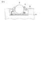
図17は、従来の超音波診断装置の操作パネル90に用いられるトラックボール装置80の側面図である。また、図19は、図18に示したトラックボール装置80の断面図である。各図に示すように、従来のトラックボール装置80は、ボール81、ボール81の一部を露出させる開口部を有するケーシング82、トラックボールとは異なる軸方向への操作に用いられるダイヤル83を具備している。ボール81は、その一部を開口部から露出させ回転自在な状態で、ケーシング82に収容される。ダイヤル83は、開口部に沿って設けられる。ユーザは、ボール81の露出した部分を手で操作し当該ボール81を回転させ、或いはダイヤル83を右回転/左回転させることで、画面上のカーソル等を操作することができる。 FIG. 17 is a side view of a
ところで、一般に、ボール81は手と接触することから汚れ易く、また、ケーシング82のボール収容部には、ゴミが溜まりやすい。特に、超音波診断装置に用いられるトラックボール装置には、超音波診断の際に患者に塗布されるゼリーが付着し易い。この様なボールの汚れやボール収容部に溜まったゴミ等は、トラックボールの検出能力を低下させる要因となる。従って、定期的なメンテナンスや清掃が不可欠である。 By the way, generally, since the
しかしながら、従来のトラックボール装置においては、メンテナンスや清掃を行う際に、例えば次のような問題がある。すなわち、ケーシング82のボール収容部からボール81を取り出すためには、計算装置の操作パネル90の表板を取り外した後操作パネル90からトラックボール装置80を取り外し、専用のネジ等を用いてトラックボール装置80を分解しなければならない。従って、トラックボール装置のメンテナンスや清掃は専門業者しか行うことができず、多大な時間と労力を必要としていた。このため、ユーザ自身による定期的な清掃ができず、ボール清掃及び孔内部からの異物除去が遅れることにより、トラックボールの検出能力を阻害しトラックボールを有する装置自体の信頼性を低下させていた。 However, the conventional trackball apparatus has the following problems when performing maintenance and cleaning, for example. That is, in order to take out the
本発明は、上記事情を鑑みてなされたもので、操作パネルからトラックボール装置を取り外す必要がなく、従って専門業者でなくともメンテナンス及び清掃が可能であるトラックボール装置、及びこれを具備する超音波診断装置を提供することを目的としている。 The present invention has been made in view of the above circumstances, and it is not necessary to remove the trackball device from the operation panel. Therefore, a trackball device that can be maintained and cleaned even by a non-specialist, and an ultrasonic wave including the trackball device. The object is to provide a diagnostic device.
本発明は、上記目的を達成するため、次のような手段を講じている。 In order to achieve the above object, the present invention takes the following measures.
請求項1に記載の発明は、所定の計算装置の操作パネルに設けられるトラックボール装置であって、収容部を有する第1のケーシングと、前記収容部内に回転自在な状態で収容されるボールと、前記収容部内に設けられ前記ボールの回転に起因する入力情報を検出する検出器と、開口部を有し、前記ボールの一部を前記開口部から露出させた状態で、且つ前記ボールを前記収容部に拘束した状態で、前記第1のケーシングに対して取り付けられる第2のケーシングと、を具備し、前記第2のケーシングは、前記開口部に沿って前記第2のケーシングから脱着可能に設けられ、当該トラックボール装置が前記操作パネルに設けられた場合に前記操作パネルから露出するリング部と、前記リング部に沿って設けられ、前記計算装置への指示を入力するためのダイヤルと、から構成され、前記第2のケーシングは、前記リング部に対して力学的作用を加えることで、前記第1のケーシングから脱着可能であることを特徴とするトラックボール装置である。
請求項14に記載の発明は、収容部を有する第1のケーシングと、前記収容部内に回転自在な状態で収容されるボールと、前記収容部内に設けられ前記ボールの回転に起因する第1の入力情報を検出する検出器と、開口部を有し、前記ボールの一部を前記開口部から露出させた状態で前記ボールを前記収容部に拘束した状態で、前記第1のケーシングに対して取り付けられる第2のケーシングと、を有するトラックボール装置を具備し、前記第2のケーシングは、前記開口部に沿って前記第2のケーシングから脱着可能に設けられ、当該トラックボール装置が前記操作パネルに設けられた場合に前記操作パネルから露出するリング部と、前記リング部に沿って設けられ、前記計算装置への指示を入力するためのダイヤルと、から構成され、
前記トラックボール装置が配置される操作パネルと、前記トラックボール装置から入力された前記第1及び第2の入力情報に従って、動作に関する制御を行う制御手段と、を具備する超音波診断装置であって、前記第2のケーシングは、前記リング部に対して力学的作用を加えることで、前記第1のケーシングから脱着可能であることを特徴とする超音波診断装置である。The invention according to claim 1 is a trackball device provided on an operation panel of a predetermined computing device, and includes a first casing having a housing portion, and a ball housed in a rotatable state in the housing portion. A detector provided in the housing for detecting input information resulting from the rotation of the ball, an opening, a part of the ball being exposed from the opening, and the ball being A second casing attached to the first casingin a state of being restrainedby the housing portion,the second casing being detachable from the second casing along the opening. When the trackball device is provided on the operation panel, a ring portion exposed from the operation panel is provided along the ring portion, and an instruction to the calculation device is input. Is composed from the dial, the second casing, the addition of mechanical action on the ring portion, a trackball device, characterized in that the detachable from said first casing.
The invention according to
An ultrasonic diagnostic apparatus comprising: an operation panel on which the trackball device is disposed; and a control unit that performs control related to an operation according tothe first and second input information input from the trackball device.the second casing, the addition of mechanical action on the ring portion, an ultrasonic diagnostic apparatus characterized byRu der removable from said first casing.
以上本発明によれば、操作パネルからトラックボール装置を取り外す必要がなく、従って専門業者でなくともメンテナンス及び清掃が可能であるトラックボール装置、及びこれを具備する超音波診断装置を実現することができる。 As described above, according to the present invention, there is no need to remove the trackball device from the operation panel, and therefore, it is possible to realize a trackball device that can be maintained and cleaned even by a non-specialist, and an ultrasonic diagnostic apparatus including the trackball device. it can.
以下、本発明の実施形態を図面に従って説明する。なお、以下の説明において、略同一の機能及び構成を有する構成要素については、同一符号を付し、重複説明は必要な場合にのみ行う。 Hereinafter, embodiments of the present invention will be described with reference to the drawings. In the following description, components having substantially the same function and configuration are denoted by the same reference numerals, and redundant description will be given only when necessary.
図1は、本実施形態に係る超音波診断装置1の外観図である。また、図2は、本実施形態に係る超音波診断装置1のブロック構成図を示している。各図に示すように、本超音波診断装置1は、装置本体11、超音波プローブ12、入力装置13、モニター14を具備している。 FIG. 1 is an external view of an ultrasonic diagnostic apparatus 1 according to the present embodiment. FIG. 2 is a block diagram of the ultrasonic diagnostic apparatus 1 according to this embodiment. As shown in each drawing, the ultrasonic diagnostic apparatus 1 includes an apparatus
超音波プローブ12は、装置本体11からの駆動信号に基づき超音波を発生し、被検体からの反射波を受信して電気信号(エコー信号)に変換する。 The
入力装置13は、装置本体11に接続され、オペレータからの各種指示、条件、関心領域(ROI)の設定指示、種々の画質条件設定指示等を装置本体11にとりこむためのトラックボール装置3、各種スイッチ、ボタン、キーボード等を有している。特に、トラックボール装置3は、例えば図1に示すように、少なくともその一部が入力装置13の操作パネル130の表板から露出するように、操作パネル130に埋め込まれて配置されている。また、トラックボール装置3は、操作パネル130の表板を取り外さない状態でボールを取り出し、ボール及びボール収容部を清掃等可能な構成を有している。当該トラックボール装置については、後で詳しく説明する。 The
モニター14は、装置本体11らのビデオ信号に基づいて、生体内の形態学的情報や、血流情報を画像として表示する。 The
装置本体11は、超音波送信ユニット21、超音波受信ユニット22、Bモード処理ユニット23、ドプラ処理ユニット24、画像生成ユニット25、画像メモリ26、画像合成ユニット27、制御プロセッサ(CPU)28、記憶ユニット29、インターフェースユニット30、ソフトウェア格納ユニット31を有している。 The apparatus
超音波送信ユニット21は、所定のレートパルスに基づくタイミングで、プローブ12に駆動パルスを印加する。超音波受信ユニット22は、エコー信号に対し受信指向性を決定するのに必要な遅延時間を与える遅延処理や加算処理等を行う。Bモード処理ユニット23は、超音波受信ユニット22からエコー信号を受け取り、対数増幅、包絡線検波処理などを施し、信号強度が輝度の明るさで表現されるデータを生成する。ドプラ処理ユニット24は、送受信ユニット22から受け取ったエコー信号から速度情報を周波数解析し、ドプラ効果による血流や組織、造影剤エコー成分を抽出する。画像生成ユニット25は、超音波スキャンの走査線信号列を、テレビなどに代表される一般的なビデオフォーマットの走査線信号列に変換し、表示画像としての超音波診断画像を生成する。画像メモリ26は、複数フレーム或いは複数ボリューム分の超音波データを一時的に記憶する。画像合成ユニット27は、画像生成ユニット25から受け取った画像を種々のパラメータの文字情報や目盛等と共に合成し、ビデオ信号としてモニター14に出力する。制御プロセッサ(CPU)28は、情報処理装置(計算機)としての機能を持ち、本超音波診断装置本体の動作を制御する。特に、制御プロセッサ28は、トラックボール装置3から入力されるユーザからの指示に従って、当該超音波診断装置1の動作を静的・動的に制御する。記憶ユニット29は、各種スキャンシーケンスを実行するためのプログラム、画像データ等を記憶する。インターフェースユニット30は、入力装置13、ネットワーク、新たな外部記憶装置(図示せず)、ネットワーク送受信等に関するインターフェースである。 The
(トラックボール装置)
次に、本超音波診断装置1が有する、トラックボール装置3の構成について詳しく説明する。このトラックボール装置3は、入力装置13の操作パネル130から露出する当該トラックボール装置3のリング部分に対し力学的作用を加えることで、操作パネル130から表板を取り外したり当該トラックボール装置3を取り外したりしなくとも、当該トラックボール装置3からボールを取り出し、ボール及びボール収容部のメンテナンスや清掃を容易ならしめるものである。(Trackball device)
Next, the configuration of the
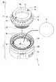
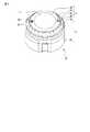
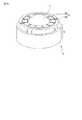
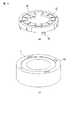
図3は、本トラックボール装置30の構成を説明するための図であり、本トラックボール装置30の分解図である。また、図4は、本トラックボール装置30の外観図である。同図に示すように、トラックボール装置3は、ボール4、第1のケーシング5、第2のケーシング6を具備している。 FIG. 3 is a diagram for explaining the configuration of the
ボール4は、少なくともその一部を露出させ且つ回転可能な状態で、第1のケーシング5内に収容される球体である。 The
第1のケーシング5は、下側基部50、検出器56、下側連結部55を有している。 The
下側基部50は、全体形状がほぼ箱状をなし、上部に開口部500、収容部501を有する筐体である。 The
収容部501は、ボール4の少なくとも一部を開口部500から露出した状態で当該ボール4を収容する。 The
検出器56は、収容部501に収容されたボール4の回転方向や速さを、直交配置され第1軸方向(例えばX軸方向)と第2軸方向(例えばY軸方向)に対応する一対のエンコーダ等である(なお、図3においては、一方の検出器56のみ図示されている)。 The
下側結合部55は、第2のケーシング6を当該第1のケーシング5に装着する際に、第2のケーシングが有する上側結合部と螺合又は嵌合する。 When the
第2のケーシング6は、上側基部60、リング62、ダイヤル63、回転方向マーク64、引っ掛け部65、上側結合部66を有している。第2のケーシング6は、リング62が操作パネル130の表面に露出する状態で第1のケーシング5に取り付けられる。 The
上側基部60は、収容部501に収容されたボール4の少なくとも一部を露出させるために開口部600を有している。 The
リング62は、第1のケーシング5の収容部501に収容されたボール4が開口部500から離脱しないようにするため(ボール4を収容部内に拘束するため)に、例えば上側基部60の開口部600の内周に沿って設けられる。また、リング62は、上側結合部66と直接的或いは間接的に連結した構造となっており、リング62を所定方向に回転或いは上下させることで、上側結合部66も同方向に回転或いは上下させることができる。 The
ダイヤル63は、例えばリング62の外周に沿って、上側基部60cに対して回転可能にもうけられる操作デバイスである。 The
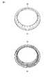
図5(a)は、ダイヤル63の表側から見た図であり、図5(b)は、ダイヤル63の裏側から見た図である。このダイヤル63を操作すること(右回転/左回転させること)により、ボール4による第1軸方向、第2軸方向とは異なる第3軸方向(例えばZ軸方向)に対応するエンコーダを制御し、当該第3軸方向についての指示を入力することが可能である。 FIG. 5A is a diagram viewed from the front side of the
また、ダイヤル63及び第1のケーシング5には、操作性の観点から、操作時に回転させた場合に、例えばユーザがマウスをクリックした場合に感じる感覚と同様の感覚(クリック感覚)を発生させるためのクリック機構が設けられている。 In addition, from the viewpoint of operability, the
図6(a)、(b)は、クリック機構を説明するための図である。また、図7(a)は図6(a)の四角内の拡大図であり、図7(b)は図6(b)の四角内の拡大図である。 6A and 6B are diagrams for explaining the click mechanism. Moreover, Fig.7 (a) is an enlarged view in the square of Fig.6 (a), FIG.7 (b) is an enlarged view in the square of FIG.6 (b).
図6(a)、図7(a)に示すように、ダイヤル63の第1のケーシング5との接触領域には、弾性部材(例えばバネ等)620が設けられている。また、図6(b)、図7(b)に示すように、第1のケーシング5のダイヤル63との接触領域には、開口部500の外周に沿って所定間隔で凹部(谷部)502が形成されている。第2のケーシング6は、弾性部材620と凹部502とが同じ高さとなるように、第1のケーシング5に装着される。ダイヤル62を回転させた場合には、弾性部材620の一部は凹部502と嵌合し、さらにダイヤル62を回転させた場合には、当該嵌合が解除されることになる。凹部502が所定間隔で形成されているため、この様な嵌合・解除は、ダイヤル62が所定角度回転する毎に繰り返されることになる。ユーザは、この様な嵌合・解除の周期的繰り返しによる抵抗(負荷)を感じることで、ダイヤル62の回転時においてクリック感覚を得ることができる。 As shown in FIGS. 6A and 7A, an elastic member (for example, a spring or the like) 620 is provided in a contact area of the
なお、この様なクリック感覚は、ダイヤル602を一定角度回転させる毎にユーザが所定の抵抗(負荷)を感じる機構であれば、どの様なものであってもよい。例えば、凹部502を凸部としてもよいし、弾性部材を第1のケーシング5側に、当該弾性部材と勘合する凹部等をダイヤル602側に設けるようにしてもよい。さらに、弾性部材と凹部・凸部によって抵抗を発生させるものに拘泥されず、例えば凹部と凸部や凸部と凸部とによって抵抗を発生させるものであってもよい。 Such a click sensation may be any mechanism as long as the user feels a predetermined resistance (load) each time the dial 602 is rotated by a certain angle. For example, the
回転方向マーク64は、例えばリング62の表面に設けられ、第2のケーシング6を第1のケーシング5から取り外す際のリング62の回転方向を示す。なお、本実施形態では、回転方向マーク64が示す方向を、第2のケーシング6を第1のケーシング5から取り外す場合のリングの回転方向とした。これとは反対に、回転方向マーク64が示す方向を、第2のケーシング6を第1のケーシング5に取り付ける場合のリングの回転方向とする構成であってもよい。 The
引っ掛け部65は、例えばリング62の表面に立体的に設けられ、第2のケーシング6を当該第1のケーシング5に装着する際に、或いは第2のケーシング6を第1のケーシング5から取り外す際に、爪や指を引っかけるための凸部である。 The
上側結合部66は、リング62と直接的或いは間接的に連結した構造となっており、第2のケーシング6を第1のケーシング5に装着する際に、第1のケーシングが有する下側結合部55と螺合又は嵌合する。また、この上側結合部と下側結合部55との螺合又は嵌合を解除することで、第1のケーシング5から第2のケーシング6を取り外すことができる。 The
上記トラックボールの操作は、次のようにして行う。すなわち、ボール4の一部は、図4に示した様に、リング62の内側(の開口部)から露出している。ユーザは、このボール4の一部を手で操作することにより、ボール4を所望の方向に、所望の速さで、所望の角度だけ回転させることで、第1軸方向、第2軸方向についての指示を入力することができる。また、同じく、ユーザは、ダイヤル63を操作すること(右回転/左回転させること)により、ボール4による第1軸方向、第2軸方向の検出に加えて、第3軸方向(例えばZ軸方向)についての指示を入力することができインターフェースユニット30を介して制御プロセッサ28に送信する。制御プロセッサ28は、ボール4やダイヤル62の操作により入力された指示に基づいて、例えばモニター14に表示されるカーソルの表示位置等を制御する。 The operation of the trackball is performed as follows. That is, a part of the
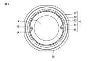
また、上記構成を持つトラックボール装置3において、第2のケーシング6の第1のケーシング5からの取り外しは、以下の様にして行うことができる。すなわち、まず、図9に示すように、引っ掛け部65に爪等を引っ掛け、回転方向マーク64の方向に所定回転数或いは所定角度だけ回転させるように、リング62に力学的作用を加える。この力学的作用により、リング62は、例えば図9に示すような状態から図10に示すような状態に回転することになる。当該回転により上側結合部66と下側結合部55との螺合又は嵌合が解除され、リング62は、最終的に、図11に示すように持ち上がった状態になる。ユーザは、持ち上がったリング62を持ち上げることで、第2のケーシング6を第1のケーシング5から取り外すことができ、収容部501に収容されたボール4を開口部500から取り出すことができる。従って、本トラックボール装置3は、操作パネル130から表板を取り外したりトラックボール装置3を取り外したりしなくとも、操作パネル130から表板側からこの様な第1のケーシング6からの第2のケーシング5を取り外したり、収容部501からボール4を取り出す等し、ボール4や収容部501の清掃、トラックボール装置3のメンテナンスをすることができる。従って、従来のようにトラックボールを取付けた電子機器のパネル等から取り外さないと清掃などが不可能であった構成と比較すると、その作業は大幅に容易化・簡略化されている。 In the
なお、リング62は、第2のケーシングから取り外し可能となっており、収容部501からボール4を取り出す際の取り出し工具としても利用することができる。 The
図12(a)、図12(b)は、取り出し工具としてリング62を用いる場合の使い方を説明するための図である。各図に示すように、収容部501に収容されたボール4をリング62の側面によって引っ掛けたり掬い出すことで、収容部501からボール4を容易に取り出すことができる。 FIG. 12A and FIG. 12B are diagrams for explaining how to use the
また、上記構成を持つトラックボール装置3において、第1のケーシング5への第2のケーシング6の取り付けは、上記取り外し操作と逆の操作を行えばよい。すなわち、ボール4を収容部501内に収容し、上側結合部66と下側結合部55との位置を対応させて第2のケーシング6を第1のケーシング5に置き、引っ掛け部65に爪等を引っ掛け、回転方向マーク64と逆方向に所定回転数或いは所定角度だけ回転させるように、リング62に力学的作用を加えることで、第2のケーシング6を第1のケーシング4に取り付けることができる。 In the
(変形例1)
本トラックボール装置3の変形例1について説明する。本変形例1に係るトラックボール装置3は、図13に示すように、ダイヤル63をリング62の内側に配置するものである。すなわち、本発明の技術的思想は、ダイヤル63とリング62との位置関係に拘泥されず、いずれが内側或いは外側であっても、同様の効果を得ることができる。(Modification 1)
A first modification of the
(変形例2)
本トラックボール装置3の変形例2について説明する。本変形例2に係るトラックボール装置3は、リング62を光らせることで、暗い場所での当該トラックボール装置3の視認性を向上させるものである。リング62を光らせるための構成は、例えば上側結合部66に導光手段を設け、第1のケーシング5内に設けられる照光源からの光を当該導光手段に導光させる、或いはリング62を蓄光素材で形成する等により実現することができる。(Modification 2)
(変形例3)
本トラックボール装置3の変形例3について説明する。本変形例3に係るトラックボール装置3は、図14(a)、(b)に示すように、第1のケーシング5の下側結合部55と第2のケーシング6の上側結合部66との関係を一方をほぞ形状とし、他方をほぞ穴形状とするのである(図14(a)、(b)の例では、上側結合部66をほぞ形状とし、下側結合部55をほぞ穴形状としている)。また、図15(a)、(b)に示すように、第1のケーシング5の下側結合部55と第2のケーシング6の上側結合部66との関係を一方を鍵形状とし、他方を鍵穴形状としてもよい(図15(a)、(b)の例では、上側結合部66を鍵形状とし、下側結合部55を鍵穴形状としている)。(Modification 3)
A third modification of the
これらの様な構成によれば、第1のケーシング5と第2のケーシング6との結合性や脱着の際の利便性をさらに向上させることができる。 According to such a configuration, it is possible to further improve the connectivity between the
(変形例4)
本トラックボール装置3の変形例4について説明する。本変形例4に係るトラックボール装置3は、図16(a)〜(d)に示すように、第1のケーシング5の開口部500形状を、円以外の楕円、多角形等にしたものである。すなわち、開口部500形状は、ボール3が取り出し可能な形状であれば、どの様な形状であってもよい。(Modification 4)
(効果)
以上述べた本トラックボール装置、及び当該トラックボール装置を具備する超音波診断装置によれば、超音波診断装置等の操作パネルから露出する当該トラックボール装置のリングに対し力学的作用を加えることで、下側結合部と上側結合部との螺合・嵌合を解除することができ、第1のケーシングから第2のケーシングの取り外し、収容部からのボールの取り出しを簡単且つ迅速に行うことができる。従って、専門業者が操作パネルから表板を取り外したり当該トラックボール装置を取り外したりしなくとも、ユーザ自身によって容易且つ迅速にボールの清掃、ボールが収容される収容部や検出器の清掃等を行い、装置を清潔に保つことができる。その結果、トラックボール装置の検出能力、トラックボール装置を有する超音波診断装置等の信頼性の低下を防止することができる。(effect)
According to the above-described trackball apparatus and the ultrasonic diagnostic apparatus including the trackball apparatus, a mechanical action is applied to the ring of the trackball apparatus exposed from the operation panel of the ultrasonic diagnostic apparatus or the like. The screwing / fitting of the lower coupling portion and the upper coupling portion can be released, and the removal of the second casing from the first casing and the removal of the ball from the housing portion can be performed easily and quickly. it can. Therefore, even if a specialist does not remove the front plate from the operation panel or the trackball device, the user himself / herself cleans the ball easily and quickly, and cleans the housing portion and detector for housing the ball. Can keep the device clean. As a result, it is possible to prevent a decrease in reliability of the detection capability of the trackball device and the ultrasonic diagnostic device having the trackball device.
なお、本発明は上記実施形態そのままに限定されるものではなく、実施段階ではその要旨を逸脱しない範囲で構成要素を変形して具体化できる。例えば、上記実施形態においては、トラックボール装置を超音波診断装置に適用した場合を例示した。しかしながら、当該例に拘泥されず、入力装置としてトラックボールを用いる他の計算装置(コンピュータ)、医用画像診断装置(X線コンピュータ断層撮影装置、磁気共鳴イメージング装置、X線診断装置、核医学診断装置等)等にも適用可能である。 Note that the present invention is not limited to the above-described embodiment as it is, and can be embodied by modifying the constituent elements without departing from the scope of the invention in the implementation stage. For example, in the above-described embodiment, the case where the trackball apparatus is applied to an ultrasonic diagnostic apparatus is illustrated. However, the present invention is not limited to this example, and other computing devices (computers), medical image diagnostic devices (X-ray computed tomography devices, magnetic resonance imaging devices, X-ray diagnostic devices, nuclear medicine diagnostic devices) that use a trackball as an input device Etc.).
また、上記実施形態に開示されている複数の構成要素の適宜な組み合わせにより、種々の発明を形成できる。例えば、実施形態に示される全構成要素から幾つかの構成要素を削除してもよい。さらに、異なる実施形態にわたる構成要素を適宜組み合わせてもよい。 In addition, various inventions can be formed by appropriately combining a plurality of components disclosed in the embodiment. For example, some components may be deleted from all the components shown in the embodiment. Furthermore, constituent elements over different embodiments may be appropriately combined.
以上本発明によれば、操作パネルからトラックボール装置を取り外す必要がなく、従って専門業者でなくともメンテナンス及び清掃が可能であるトラックボール装置、及びこれを具備する超音波診断装置を実現することができる。 As described above, according to the present invention, there is no need to remove the trackball device from the operation panel, and therefore, it is possible to realize a trackball device that can be maintained and cleaned even by a non-specialist, and an ultrasonic diagnostic apparatus including the trackball device. it can.
1…超音波診断装置、3…トラックボール装置、4…ボール、5…第1のケーシング、6…第2のケーシング、11…装置本体、12…超音波プローブ、13…入力装置、14…モニター、21…超音波送信ユニット、22…超音波受信ユニット、23…Bモード処理ユニット、24…ドプラ処理ユニット、25…画像生成ユニット、26…画像メモリ、27…画像合成ユニット、28…制御プロセッサ(CPU)、29…記憶ユニット、30…インターフェースユニット、31…ソフトウェア格納ユニット、50…下側基部、55…下側連結部、56…検出器、60…上側基部、62…リング、63…ダイヤル、64…回転方向マーク、65…引っ掛け部、66…上側結合部、130…操作パネル、500…開口部、501…収容部、600…開口部DESCRIPTION OF SYMBOLS 1 ... Ultrasonic diagnostic apparatus, 3 ... Track ball apparatus, 4 ... Ball, 5 ... 1st casing, 6 ... 2nd casing, 11 ... Apparatus main body, 12 ... Ultrasonic probe, 13 ... Input device, 14 ... Monitor , 21 ... Ultrasonic transmission unit, 22 ... Ultrasonic reception unit, 23 ... B-mode processing unit, 24 ... Doppler processing unit, 25 ... Image generation unit, 26 ... Image memory, 27 ... Image composition unit, 28 ... Control processor ( CPU), 29 ... storage unit, 30 ... interface unit, 31 ... software storage unit, 50 ... lower base, 55 ... lower connection, 56 ... detector, 60 ... upper base, 62 ... ring, 63 ... dial, 64 ... Rotation direction mark, 65 ... Hook, 66 ... Upper coupling part, 130 ... Operation panel, 500 ... Opening part, 501 ... Housing part, 60 ... opening
Claims (26)
Translated fromJapanese収容部を有する第1のケーシングと、
前記収容部内に回転自在な状態で収容されるボールと、
前記収容部内に設けられ前記ボールの回転に起因する入力情報を検出する検出器と、
開口部を有し、前記ボールの一部を前記開口部から露出させた状態で、且つ前記ボールを前記収容部に拘束した状態で、前記第1のケーシングに対して取り付けられる第2のケーシングと、
を具備し、
前記第2のケーシングは、
前記開口部に沿って前記第2のケーシングから脱着可能に設けられ、当該トラックボール装置が前記操作パネルに設けられた場合に前記操作パネルから露出するリング部と、
前記リング部に沿って設けられ、前記計算装置への指示を入力するためのダイヤルと、
から構成され、
前記第2のケーシングは、前記リング部に対して力学的作用を加えることで、前記第1のケーシングから脱着可能であること
を特徴とするトラックボール装置。A trackball device provided on an operation panel of a predetermined computing device,
A first casing having a receiving portion;
A ball housed in a rotatable state in the housing part;
A detector provided in the housing portion for detecting input information resulting from the rotation of the ball;
A second casing attached to the first casing with an opening, with a portion of the ball exposed from the opening, and with the ball restrainedby the housing ,
Comprising
The second casing is
A ring portion that is detachably provided from the second casing along the opening, and is exposed from the operation panel when the trackball device is provided on the operation panel;
A dial provided along the ring portion for inputting instructions to the computing device;
Consisting of
The trackball device,wherein the second casing is detachable from the first casing by applying a mechanical action to the ring portion.
前記第1のケーシングは第2嵌合部材を更に有し、 The first casing further includes a second fitting member;
前記第2のケーシングが前記第1のケーシングに取り付けられた場合に、前記ダイヤルと前記第1のケーシングとの接触領域は、前記第1及び第2嵌合部材によって嵌合すること When the second casing is attached to the first casing, a contact area between the dial and the first casing is fitted by the first and second fitting members.
を特徴とする請求項1に記載のトラックボール装置。 The trackball device according to claim 1.
前記第2嵌合部材は前記弾性部材と嵌合する凹部によって構成されることThe second fitting member is constituted by a recess that fits with the elastic member.
を The
請求項2または3記載のトラックボール装置。The trackball device according to claim 2 or 3.
を特徴とする請求項1乃至4のいずれか一項記載のトラックボール装置。 The trackball device according to any one of claims 1 to 4, wherein:
前記リング部は前記第2のケーシングから外された状態で、前記円筒形状の内壁側面によって前記ボールを保持可能に設けられること The ring portion is provided so as to be able to hold the ball by the cylindrical inner wall side surface in a state of being removed from the second casing.
を特徴とする請求項5に記載のトラックボール装置。 The trackball device according to claim 5.
を特徴とする請求項1乃至6に記載のトラックボール装置。The trackball device according to claim 1, wherein:
前記リング部に対して前記力学的作用を加えることで、前記螺合が解除されること、
を特徴とする請求項1乃至7のいずれか一項記載のトラックボール装置。The first casing and the second casing are screwed together,
The screwing is released by applying the mechanical action to the ring portion;
A trackball device according toany one of claims 1 to 7 .
前記リング部に対して前記力学的作用を加えることで、前記嵌合が解除されること、
を特徴とする請求項1乃至7のいずれか一項記載のトラックボール装置。The second casing and the first casing are fitted,
The fitting is released by applying the mechanical action to the ring portion;
A trackball device according toany one of claims 1 to 7 .
前記収容部内に回転自在な状態で収容されるボールと、
前記収容部内に設けられ前記ボールの回転に起因する第1の入力情報を検出する検出器と、
開口部を有し、前記ボールの一部を前記開口部から露出させた状態で前記ボールを前記収容部に拘束した状態で、前記第1のケーシングに対して取り付けられる第2のケーシングと、
を有するトラックボール装置を具備し、
前記第2のケーシングは、
前記開口部に沿って前記第2のケーシングから脱着可能に設けられ、当該トラックボール装置が前記操作パネルに設けられた場合に前記操作パネルから露出するリング部と、
前記リング部に沿って設けられ、前記計算装置への指示を入力するためのダイヤルと、
から構成され、
前記トラックボール装置が配置される操作パネルと、
前記トラックボール装置から入力された前記第1及び第2の入力情報に従って、動作に関する制御を行う制御手段と、
を具備する超音波診断装置であって、
前記第2のケーシングは、前記リング部に対して力学的作用を加えることで、前記第1のケーシングから脱着可能であること
を特徴とする超音波診断装置。A first casing having a receiving portion;
A ball housed in a rotatable state in the housing part;
A detector that is provided in the housing and detectsfirst input information resulting from rotation of the ball;
A second casing attached to the first casingin a state in which the ball is constrainedto the accommodating portionin a state where the ball has an opening, and a part of the ball is exposed from the opening,
Comprising a trackball device having
The second casing is
A ring portion that is detachably provided from the second casing along the opening, and is exposed from the operation panel when the trackball device is provided on the operation panel;
A dial provided along the ring portion for inputting instructions to the computing device;
Consisting of
An operation panel on which the trackball device is disposed;
Control means for controlling the operation according tothe first and second input information input from the trackball device;
An ultrasonic diagnostic apparatus comprising:
Said second casing, said by adding mechanical action with respect to the ring portion, an ultrasonic diagnostic apparatus characterized byRu der removable from said first casing.
前記第1のケーシングは第2嵌合部材を更に有し、 The first casing further includes a second fitting member;
前記第2のケーシングが前記第1のケーシングに取り付けられた場合に、前記ダイヤルと前記第1のケーシングとの接触領域は、前記第1及び第2嵌合部材によって嵌合すること When the second casing is attached to the first casing, a contact area between the dial and the first casing is fitted by the first and second fitting members.
を特徴とする請求項14に記載の超音波診断装置。 The ultrasonic diagnostic apparatus according to claim 14.
前記第2嵌合部材は前記弾性部材と嵌合する凹部によって構成されることThe second fitting member is constituted by a recess that fits with the elastic member.
を特徴とする請求項15または16に記載の超音波診断装置。 The ultrasonic diagnostic apparatus according to claim 15 or 16.
を特徴とする請求項14乃至17のいずれか一項記載の超音波診断装置。 The ultrasonic diagnostic apparatus according to claim 14, wherein:
前記リング部は前記第2のケーシングから外された状態で、前記円筒形状の内壁側面によって前記ボールを保持可能に設けられること The ring portion is provided so as to be able to hold the ball by the cylindrical inner wall side surface in a state of being removed from the second casing.
を特徴とする請求項18に記載の超音波診断装置。 The ultrasonic diagnostic apparatus according to claim 18.
を特徴とする請求項14乃至19に記載の超音波診断装置。 The ultrasonic diagnostic apparatus according to claim 14, wherein:
前記リング部に対して前記力学的作用を加えることで、前記螺合が解除されること
を特徴とする請求項14乃至20のいずれか一項記載の超音波診断装置。The first casing and the second casing are screwed together,
The ultrasonic diagnostic apparatus according toany one of claims 14 to 20 , wherein the screwing is released by applying the mechanical action to the ring portion.
前記リング部に対して前記力学的作用を加えることで、前記嵌合が解除されること
を特徴とする請求項14乃至20のいずれか一項記載の超音波診断装置。The second casing and the first casing are fitted,
The ultrasonic diagnostic apparatus according toany one of claims 14 to 20 , wherein the fitting is released by applying the mechanical action to the ring portion.
Priority Applications (4)
| Application Number | Priority Date | Filing Date | Title |
|---|---|---|---|
| JP2010078802AJP5424490B2 (en) | 2010-03-30 | 2010-03-30 | Trackball device and ultrasonic diagnostic device |
| US13/074,436US9261986B2 (en) | 2010-03-30 | 2011-03-29 | Trackball device and ultrasonic diagnostic apparatus |
| CN201410652777.6ACN104317431A (en) | 2010-03-30 | 2011-03-30 | Trackball device and ultrasonic diagnostic apparatus |
| CN201110081416.7ACN102253732B (en) | 2010-03-30 | 2011-03-30 | Trackball device and ultrasonic diagnostic device |
Applications Claiming Priority (1)
| Application Number | Priority Date | Filing Date | Title |
|---|---|---|---|
| JP2010078802AJP5424490B2 (en) | 2010-03-30 | 2010-03-30 | Trackball device and ultrasonic diagnostic device |
Publications (2)
| Publication Number | Publication Date |
|---|---|
| JP2011210113A JP2011210113A (en) | 2011-10-20 |
| JP5424490B2true JP5424490B2 (en) | 2014-02-26 |
Family
ID=44709033
Family Applications (1)
| Application Number | Title | Priority Date | Filing Date |
|---|---|---|---|
| JP2010078802AActiveJP5424490B2 (en) | 2010-03-30 | 2010-03-30 | Trackball device and ultrasonic diagnostic device |
Country Status (3)
| Country | Link |
|---|---|
| US (1) | US9261986B2 (en) |
| JP (1) | JP5424490B2 (en) |
| CN (2) | CN102253732B (en) |
Families Citing this family (9)
| Publication number | Priority date | Publication date | Assignee | Title |
|---|---|---|---|---|
| CN103054612B (en)* | 2012-12-10 | 2015-06-10 | 苏州佳世达电通有限公司 | Ultrasonic probe mouse and ultrasonoscope |
| CN107683451B (en) | 2015-06-30 | 2020-09-11 | 奥林巴斯株式会社 | Medical input device |
| US10705629B1 (en)* | 2016-08-03 | 2020-07-07 | Apple Inc. | Customizable control system |
| USD928156S1 (en) | 2019-11-26 | 2021-08-17 | ACCO Brands Corporation | Computer input device |
| US11048347B2 (en) | 2019-11-26 | 2021-06-29 | ACCO Brands Corporation | Computer input device |
| USD950552S1 (en) | 2020-05-06 | 2022-05-03 | ACCO Brands Corporation | Computer input device |
| US11531411B2 (en)* | 2020-05-29 | 2022-12-20 | ACCO Brands Corporation | Computer input device |
| CN115480630A (en)* | 2021-05-31 | 2022-12-16 | 通用电气精准医疗有限责任公司 | Trackball device, medical input device, and ultrasonic imaging device |
| TWI817452B (en)* | 2022-01-03 | 2023-10-01 | 致伸科技股份有限公司 | Input device |
Family Cites Families (21)
| Publication number | Priority date | Publication date | Assignee | Title |
|---|---|---|---|---|
| JPH05168624A (en)* | 1991-12-26 | 1993-07-02 | Toshiba Corp | Operation panel for ultrasonic diagnostic equipment |
| JPH05233141A (en)* | 1992-02-25 | 1993-09-10 | Mitsubishi Electric Corp | pointing device |
| US5589828A (en)* | 1992-03-05 | 1996-12-31 | Armstrong; Brad A. | 6 Degrees of freedom controller with capability of tactile feedback |
| US5561445A (en)* | 1992-11-09 | 1996-10-01 | Matsushita Electric Industrial Co., Ltd. | Three-dimensional movement specifying apparatus and method and observational position and orientation changing apparatus |
| JP2607774Y2 (en)* | 1993-11-18 | 2002-07-08 | 多摩川精機株式会社 | Track ball |
| CN2198653Y (en) | 1994-02-02 | 1995-05-24 | 旭丽股份有限公司 | trackball stand |
| US5486845A (en)* | 1994-03-10 | 1996-01-23 | Chait; Abraham I. | Non-linting ball gasket for computer mouse devices and method |
| SE9501023L (en)* | 1995-03-22 | 1996-03-11 | Arthur E Strandberg | Trackball with cleaning function |
| JPH0916326A (en)* | 1995-06-27 | 1997-01-17 | Tamagawa Seiki Co Ltd | Trackball equipment |
| JP2000102674A (en)* | 1998-07-31 | 2000-04-11 | Sony Computer Entertainment Inc | Entertainment system, supplying carrier and input control device |
| AU1761401A (en)* | 1999-11-12 | 2001-06-06 | Acco Brands, Inc. | A pointing device with an annular rotating ring |
| JP3728523B2 (en)* | 2000-12-22 | 2005-12-21 | 神田通信工業株式会社 | Trackball ball take-out structure |
| JP2002236553A (en)* | 2001-02-09 | 2002-08-23 | Furuno Electric Co Ltd | Track ball unit |
| JP4075335B2 (en)* | 2001-04-11 | 2008-04-16 | 松下電器産業株式会社 | Electronics |
| JP3915071B2 (en)* | 2002-11-22 | 2007-05-16 | 東京測定器材株式会社 | Trackball |
| CN2672750Y (en) | 2003-11-27 | 2005-01-19 | 联想(北京)有限公司 | Mouse |
| CN1912812A (en) | 2005-08-09 | 2007-02-14 | 深圳迈瑞生物医疗电子股份有限公司 | Easy disassemblied tracing-ball device |
| US7659883B2 (en)* | 2006-03-20 | 2010-02-09 | Tech-Way Computer Co., Ltd. | Joystick device configured with a mouse unit |
| CN100536797C (en) | 2006-08-07 | 2009-09-09 | 深圳迈瑞生物医疗电子股份有限公司 | Medical diagnostic system and its control panel |
| JP4393506B2 (en) | 2006-11-27 | 2010-01-06 | 株式会社日立メディコ | Ultrasonic diagnostic equipment |
| JP2010055166A (en)* | 2008-08-26 | 2010-03-11 | Tokai Rika Co Ltd | Information selector |
- 2010
- 2010-03-30JPJP2010078802Apatent/JP5424490B2/enactiveActive
- 2011
- 2011-03-29USUS13/074,436patent/US9261986B2/enactiveActive
- 2011-03-30CNCN201110081416.7Apatent/CN102253732B/enactiveActive
- 2011-03-30CNCN201410652777.6Apatent/CN104317431A/enactivePending
Also Published As
| Publication number | Publication date |
|---|---|
| CN104317431A (en) | 2015-01-28 |
| US9261986B2 (en) | 2016-02-16 |
| US20110241994A1 (en) | 2011-10-06 |
| JP2011210113A (en) | 2011-10-20 |
| CN102253732A (en) | 2011-11-23 |
| CN102253732B (en) | 2015-02-18 |
Similar Documents
| Publication | Publication Date | Title |
|---|---|---|
| JP5424490B2 (en) | Trackball device and ultrasonic diagnostic device | |
| US20230267699A1 (en) | Methods and apparatuses for tele-medicine | |
| US20090131793A1 (en) | Portable imaging system having a single screen touch panel | |
| CN101658431B (en) | Systems and methods for visualization of ultrasound probe relative to object | |
| US9622722B2 (en) | Portable imaging system having a seamless form factor | |
| US9414804B2 (en) | Diagnostic imaging device having protective facade and method of cleaning and disinfecting same | |
| JP2009056202A (en) | Ultrasonic diagnostic apparatus | |
| US20130237824A1 (en) | Method for providing ultrasound images and ultrasound apparatus | |
| CN103889336A (en) | Ultrasonic diagnostic imaging system with contextually variable control panel | |
| JP2010221033A (en) | System and method for displaying ultrasonic motion tracking information | |
| CN111904462A (en) | Method and system for presenting functional data | |
| EP1829483A1 (en) | Ultrasonic diagnostic apparatus and ultrasonic diagnostic processing method | |
| JP2010017558A (en) | Ultrasonic system and method for providing pictorial keyboard | |
| CN112237447A (en) | Method and system for periodic imaging | |
| JP2016501625A (en) | Ultrasound imaging with variable line density | |
| US20170055953A1 (en) | Medical image diagnostic apparatus and medical imaging apparatus | |
| US20210378483A1 (en) | Control and input device for medical observation device incorporating pointing device with co-located soft and hard inputs and graphical user interface | |
| KR102593439B1 (en) | Method for controlling ultrasound imaging apparatus and ultrasound imaging aparatus thereof | |
| JP2010142399A (en) | Ultrasonic diagnostic apparatus | |
| KR20140128504A (en) | ultrasonic probe and ultrasonic imaging apparatus | |
| JP2012205722A (en) | Operation panel cover of ultrasonic diagnostic apparatus | |
| JP7545794B2 (en) | Ultrasound diagnostic device, medical image processing device, and ultrasound image display program | |
| US20240237969A1 (en) | Medical image diagnosis device and medical image diagnosis system | |
| JP2024024441A (en) | Ultrasonic probe and ultrasonic diagnostic equipment | |
| EP4580507A1 (en) | Ultrasound exam tracking |
Legal Events
| Date | Code | Title | Description |
|---|---|---|---|
| A621 | Written request for application examination | Free format text:JAPANESE INTERMEDIATE CODE: A621 Effective date:20130226 | |
| A977 | Report on retrieval | Free format text:JAPANESE INTERMEDIATE CODE: A971007 Effective date:20130731 | |
| A131 | Notification of reasons for refusal | Free format text:JAPANESE INTERMEDIATE CODE: A131 Effective date:20130806 | |
| A521 | Request for written amendment filed | Free format text:JAPANESE INTERMEDIATE CODE: A523 Effective date:20131007 | |
| TRDD | Decision of grant or rejection written | ||
| A01 | Written decision to grant a patent or to grant a registration (utility model) | Free format text:JAPANESE INTERMEDIATE CODE: A01 Effective date:20131029 | |
| A61 | First payment of annual fees (during grant procedure) | Free format text:JAPANESE INTERMEDIATE CODE: A61 Effective date:20131125 | |
| R150 | Certificate of patent or registration of utility model | Free format text:JAPANESE INTERMEDIATE CODE: R150 Ref document number:5424490 Country of ref document:JP Free format text:JAPANESE INTERMEDIATE CODE: R150 | |
| S533 | Written request for registration of change of name | Free format text:JAPANESE INTERMEDIATE CODE: R313533 | |
| R350 | Written notification of registration of transfer | Free format text:JAPANESE INTERMEDIATE CODE: R350 |