Movatterモバイル変換


[0]ホーム

URL:


JP5424455B2 - Suture needle case - Google Patents

Suture needle case
Download PDF

Info

Publication number
JP5424455B2
JP5424455B2JP2008335643AJP2008335643AJP5424455B2JP 5424455 B2JP5424455 B2JP 5424455B2JP 2008335643 AJP2008335643 AJP 2008335643AJP 2008335643 AJP2008335643 AJP 2008335643AJP 5424455 B2JP5424455 B2JP 5424455B2
Authority
JP
Japan
Prior art keywords
case
suture needle
needle
main body
suture
Prior art date
Legal status (The legal status is an assumption and is not a legal conclusion. Google has not performed a legal analysis and makes no representation as to the accuracy of the status listed.)
Active
Application number
JP2008335643A
Other languages
Japanese (ja)
Other versions
JP2010154989A (en
Inventor
雅也 鈴木
Current Assignee (The listed assignees may be inaccurate. Google has not performed a legal analysis and makes no representation or warranty as to the accuracy of the list.)
Livedo Corp
Original Assignee
Livedo Corp
Priority date (The priority date is an assumption and is not a legal conclusion. Google has not performed a legal analysis and makes no representation as to the accuracy of the date listed.)
Filing date
Publication date
Application filed by Livedo CorpfiledCriticalLivedo Corp
Priority to JP2008335643ApriorityCriticalpatent/JP5424455B2/en
Publication of JP2010154989ApublicationCriticalpatent/JP2010154989A/en
Application grantedgrantedCritical
Publication of JP5424455B2publicationCriticalpatent/JP5424455B2/en
Activelegal-statusCriticalCurrent
Anticipated expirationlegal-statusCritical

Links

Images

Landscapes

Description

Translated fromJapanese

本発明は、使用済みの手術用縫合針を収容する縫合針ケースに関する。  The present invention relates to a suture needle case that accommodates a used surgical suture needle.

従来より、縫合針が使用される外科手術では、患者の体内に縫合針が残置されてしまうことを防止するために、使用済みの縫合針の本数を数えることが行われている。特許文献1では、スポンジやコルク等にて形成された針刺固定体を土台に対して斜めに取り付けた手術用縫合針カウンターが開示されている。特許文献1の手術用縫合針カウンターを使用する際には、縫合針を把持した持針器を縫合針の湾曲に合わせて回転させることにより、縫合針の先端が針刺固定体に差し込まれて縫合針が針刺固定体に固定される。手術用縫合針カウンターでは、土台上面の針刺固定体近傍に縫合針の計数に利用される番号が印刷されている。手術用縫合針カウンターに固定された縫合針の計数が終了すると、針刺固定体は土台から取り外されて廃棄用容器内に収容されて廃棄される。  Conventionally, in a surgical operation in which a suture needle is used, the number of used suture needles is counted in order to prevent the suture needle from being left in the patient's body.Patent Document 1 discloses a surgical needle counter in which a needle stick fixing body formed of sponge, cork, or the like is attached obliquely to a base. When using the surgical suture needle counter ofPatent Document 1, the needle holder holding the suture needle is rotated in accordance with the curvature of the suture needle, so that the distal end of the suture needle is inserted into the needlestick fixing body. The suture needle is fixed to the needle stick fixing body. In the surgical needle counter, a number used for counting suture needles is printed in the vicinity of the needle stick fixing body on the upper surface of the base. When the counting of the suture needles fixed to the surgical suture needle counter is completed, the needlestick fixed body is removed from the base, accommodated in a disposal container, and discarded.

特許文献2では、スポンジにて形成された複数の円柱状または五角形以上の角柱状のカウンター本体が、セパレート材の剥離面上に剥離可能に接着された縫合針カウンターが開示されている。縫合針カウンターが使用される際には、カウンター本体がセパレート材から剥離され、未使用の縫合針が収容されているパッケージに貼り付けられる。カウンター本体の上面には縫合針の計数に利用される番号が印刷されており、使用済みの縫合針は、カウンター本体の側面の当該番号に対応する位置に順番に刺されてカウンター本体に固定される。
特許第3705416号公報特許第3970265号公報
Patent Document 2 discloses a suture needle counter in which a plurality of columnar or pentagonal or more prismatic counter bodies formed of sponge are detachably bonded onto a separation surface of a separate material. When the suture needle counter is used, the counter body is peeled from the separate material and attached to a package containing unused suture needles. A number used to count the suture needle is printed on the upper surface of the counter body, and the used suture needles are sequentially inserted into positions corresponding to the numbers on the side surface of the counter body and fixed to the counter body. .
Japanese Patent No. 3705416 Japanese Patent No. 3970265

ところで、特許文献1の手術用縫合針カウンターでは、先端に縫合針が把持された持針器を回転させることにより針刺固定体に縫合針を刺す必要があるため、持針器の操作に慣れていないと容易に縫合針を固定することができない。また、特許文献2の縫合針カウンターにおいても同様に、縫合針をカウンター本体に容易に固定することができず、カウンター本体の側面のうち持針器を持つ手とは反対側の側面に縫合針を刺す際には、縫合針の固定がさらに難しくなる。  By the way, in the surgical suture needle counter ofPatent Document 1, since it is necessary to pierce the needle stick fixed body by rotating the needle holder with the suture needle held at the tip, it is used to the operation of the needle holder. Otherwise, the suture needle cannot be fixed easily. Similarly, in the suture needle counter of Patent Document 2, the suture needle cannot be easily fixed to the counter body, and the suture needle is placed on the side surface of the counter body opposite to the hand holding the needle holder. When inserting a needle, it becomes more difficult to fix the suture needle.

また、特許文献1および特許文献2の縫合針カウンターでは、縫合針がスポンジ等の柔らかい材料により形成された針刺固定体やカウンター本体に刺されるため、針刺固定体やカウンター本体を掴んで縫合針の計数が行われたり針刺固定体やカウンター本体が移動される際等に、縫合針の先端が針刺固定体やカウンター本体を突き抜けて手に刺さってしまう可能性がある。  Further, in the suture needle counters ofPatent Document 1 and Patent Document 2, since the suture needle is inserted into a needle stick fixing body or counter body formed of a soft material such as sponge, the needle needle fixing body or counter body is grasped and sutured. When the needle is counted or the needle stick fixing body or the counter main body is moved, the tip of the suture needle may penetrate the needle stick fixing body or the counter main body and pierce the hand.

本発明は、上記課題に鑑みなされたものであり、縫合針の計数を安全かつ正確に行うことを目的としている。  The present invention has been made in view of the above problems, and an object of the present invention is to perform counting of suture needles safely and accurately.

請求項1に記載の発明は、使用済みの手術用縫合針を収容する縫合針ケースであって、ケース底部と前記ケース底部の全周を囲むケース周壁部とを有するケース本体と、前記ケース本体の上部開口を閉塞する蓋部とを備え、前記ケース底部および前記蓋部の少なくとも一部が、内部に収容された手術用縫合針を計数するための透光性を有する透光部となっており、前記ケース底部の内面のおよそ全面に亘って凹凸構造が形成されており、縫合針が収容される場合に前記縫合針の一部が前記凹凸構造と離間する
請求項2に記載の発明は、請求項1に記載の縫合針ケースであって、前記ケース本体が、樹脂シートから成形される。
請求項3に記載の発明は、請求項1に記載の縫合針ケースであって、前記蓋部の周縁部の一部と前記ケース周壁部の上端部の一部とが可撓性を有する接続部にて接続されている。
請求項4に記載の発明は、請求項3に記載の縫合針ケースであって、前記蓋部および前記ケース本体の全体が樹脂により一体的に成形されている。
請求項5に記載の発明は、請求項4に記載の縫合針ケースであって、前記蓋部および前記ケース本体が、樹脂シートから成形される。
請求項6に記載の発明は、使用済みの手術用縫合針を収容する縫合針ケースであって、ケース底部と前記ケース底部の全周を囲むケース周壁部とを有するケース本体と、前記ケース本体の上部開口を閉塞する蓋部とを備え、前記ケース底部および前記蓋部の少なくとも一部が、内部に収容された手術用縫合針を計数するための透光性を有する透光部となっており、前記ケース底部の内面のおよそ全面に亘って凹凸構造が形成されており、前記蓋部が、前記ケース本体と同様の構造を有するもう1つのケース本体であり、前記もう1つのケース本体のケース底部を前記ケース本体の前記上部開口に重ねて前記もう1つのケース本体を前記ケース本体に向かって押圧することにより、前記上部開口が閉塞される。
The invention according toclaim 1 is a suturing needle case for housing a used surgical suturing needle, the case main body having a case bottom and a case peripheral wall surrounding the entire circumference of the case bottom, and the case main body A lid portion that closes the upper opening of the case, and at least a part of the case bottom and the lid portion is a translucent portion having translucency for counting the surgical suture needles housed therein. A concavo-convex structure is formed over substantially the entire inner surface of the case bottom, and a part ofthe suturing needle is separated from the concavo-convex structure when the suturing needle is accommodated .
The invention according to claim 2 is the suturing needle case according toclaim 1, wherein the case main body is molded from a resin sheet.
The invention according toclaim 3 is the suturing needle case according toclaim 1, wherein a part of the peripheral edge of the lid part and a part of the upper end part of the case peripheral wall part are flexible. Connected at each part.
The invention according to claim 4 is the suturing needle case according toclaim 3, wherein the entire lid and the case main body are integrally formed of resin.
The invention according to claim 5 is the suturing needle case according to claim 4, wherein the lid and the case main body are molded from a resin sheet.
The invention according to claim 6 is a suturing needle case for housing a used surgical suturing needle, the case main body having a case bottom and a case peripheral wall surrounding the entire circumference of the case bottom, and the case main body A lid portion that closes the upper opening of the case, and at least a part of the case bottom and the lid portion is a translucent portion having translucency for counting the surgical suture needles housed therein. A concave-convex structure is formed over substantially the entire inner surface of the case bottom, and the lid is another case body having the same structure as the case body, and the other case body The upper opening is closed by putting the case bottom on the upper opening of the case body and pressing the other case body toward the case body.

請求項に記載の発明は、請求項に記載の縫合針ケースであって、前記ケース本体が、樹脂シートから成形される。
請求項8に記載の発明は、請求項1ないし7のいずれかに記載の縫合針ケースであって、前記凹凸構造の一の方向に垂直な断面の形状が一定である。
The invention according to claim7 is the suturing needle case according to claim6 , wherein the case main body is formed from a resin sheet.
The invention according to claim 8 is the suturing needle case according to any one ofclaims 1 to 7, wherein a shape of a cross section perpendicular to one direction of the concavo-convex structure is constant.

本発明では、縫合針の計数を安全かつ正確に行うことができる。また、請求項2、5およびの発明では、ケース底部に凹凸構造を容易に設けることができる。請求項の発明では、ケース本体と蓋部とを区別することなく、容易に縫合針を収容することができる。請求項の発明では、使用時に蓋部およびケース本体を個別に扱う必要がないため、容易かつ迅速にケース本体の上部開口を閉塞することができる。In the present invention, the counting of the suture needle can be performed safely and accurately. In the inventions of claims2, 5 and7 , the concavo-convex structure can be easily provided on the case bottom. In the invention of claim6 , the suture needle can be easily accommodated without distinguishing between the case main body and the lid. In the invention ofclaim3 , since it is not necessary to handle the lid and the case main body individually during use, the upper opening of the case main body can be closed easily and quickly.

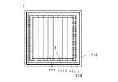
図1は、本発明の第1の実施の形態に係る縫合針ケースセット3の使用前の状態を示す平面図である。縫合針ケースセット3は、外科手術において使用された使用済みの手術用縫合針(以下、単に「縫合針」という。)の収容に利用され、図1に示すように、平面視において略矩形の複数(本実施の形態では、8つ)のケース本体11を備える。複数のケース本体11は、互いに同様の構造を有する。  FIG. 1 is a plan view showing a state before use of the suture needle case set 3 according to the first embodiment of the present invention. The sutureneedle case set 3 is used for housing a used surgical suture needle (hereinafter simply referred to as “suture needle”) used in a surgical operation, and has a substantially rectangular shape in a plan view as shown in FIG. A plurality (eight in this embodiment) ofcase bodies 11 are provided. The plurality ofcase bodies 11 have the same structure.

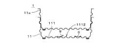
図2は、縫合針ケースセット3の一部を図1中のA−Aの位置にて切断した部分断面図である。図1および図2に示すように、ケース本体11は、平面視において略矩形(本実施の形態では、略正方形)のケース底部111、および、ケース底部111の全周を囲むとともにケース底部111から上方に向かって立ち上がるケース周壁部112を備え、ケース本体11の上端には、図2に示すように、上部開口110が形成されている。ケース本体11のケース底部111およびケース周壁部112の全体は、薄肉の樹脂シートから一体的に成形されている。図2では、図示の都合上、ケース本体11の断面を実線のみにて示す(図4.A、図4.Bおよび図5においても同様)。  FIG. 2 is a partial cross-sectional view of a part of the suture needle case set 3 cut at the position AA in FIG. As shown in FIGS. 1 and 2, the casemain body 11 surrounds thecase bottom 111 having a substantially rectangular shape (substantially square in the present embodiment) in plan view, and surrounds the entire circumference of thecase bottom 111 and from thecase bottom 111. A caseperipheral wall portion 112 rising upward is provided, and anupper opening 110 is formed at the upper end of thecase body 11 as shown in FIG. Theentire case bottom 111 and caseperipheral wall 112 of thecase body 11 are integrally formed from a thin resin sheet. 2, for convenience of illustration, the cross section of the casemain body 11 is shown only by a solid line (the same applies to FIGS. 4.A, 4.B, and 5).

ケース底部111およびケース周壁部112は、それぞれを介してケース本体11の内部が視認可能となるように透光性を有する。ケース本体11は、ケース底部111の各辺の長さがケース本体11の深さ(すなわち、ケース周壁部112の高さ)よりも大きい浅底型となっており、平坦な場所(例えば、手術室内において医療用品が載置されるワゴン)に安定して載置することができる。  Thecase bottom part 111 and the caseperipheral wall part 112 have translucency so that the inside of the casemain body 11 can be visually recognized through each. The casemain body 11 is a shallow bottom type in which the length of each side of thecase bottom portion 111 is larger than the depth of the case main body 11 (that is, the height of the case peripheral wall portion 112). It can be stably placed on a wagon where medical supplies are placed indoors.

ケース本体11のケース底部111の下面(外面)の外周部は、外側に向かうに従って(すなわち、ケース底部111の中心から離れるに従って)上方に傾斜する傾斜面とされる。また、ケース本体11では、薄肉のケース底部111のおよそ全面に亘って凹凸構造(以下、「底部凹凸構造1112」という。)が形成されており、底部凹凸構造1112は、図2の紙面に垂直な方向(以下、「奥行方向」という。)に関して同様の断面形状を有する。換言すれば、ケース底部111の上面および下面(すなわち、ケース底部111の内面および外面)のおよそ全面に亘って底部凹凸構造1112が形成されており、底部凹凸構造1112は、図2の奥行方向に垂直な断面の形状が一定である。  The outer peripheral portion of the lower surface (outer surface) of thecase bottom 111 of thecase body 11 is an inclined surface that is inclined upward as it goes outward (that is, away from the center of the case bottom 111). Further, in the casemain body 11, an uneven structure (hereinafter referred to as “bottomuneven structure 1112”) is formed over almost the entire surface of thethin case bottom 111, and the bottomuneven structure 1112 is perpendicular to the paper surface of FIG. A similar cross-sectional shape with respect to any direction (hereinafter referred to as “depth direction”). In other words, the bottomuneven structure 1112 is formed over substantially the entire upper and lower surfaces of the case bottom 111 (that is, the inner and outer surfaces of the case bottom 111), and the bottomuneven structure 1112 extends in the depth direction of FIG. The shape of the vertical cross section is constant.

図2中において符号Dを付して示す底部凹凸構造1112の最小繰り返しピッチ(すなわち、隣接する2つの凸部の頂部の間の最小距離)は、1mm以上、かつ、ケース本体11に収容される縫合針の最小曲率半径の4倍以下とされる。また、図2中において符号Hを付して示す底部凹凸構造1112の高さ(すなわち、上下方向における凸部の頂部と凹部の底部との間の距離)は、0.5mm以上、かつ、ケース本体11に収容される縫合針の最小曲率半径以下とされる。  The minimum repetitive pitch (that is, the minimum distance between the tops of two adjacent convex portions) of the bottom concavo-convex structure 1112 indicated by reference sign D in FIG. 2 is 1 mm or more and is accommodated in thecase body 11. The minimum curvature radius of the suture needle is 4 times or less. Further, the height of the bottom concavo-convex structure 1112 indicated by symbol H in FIG. 2 (that is, the distance between the top of the convex portion and the bottom of the concave portion in the vertical direction) is 0.5 mm or more, and the case The radius of curvature is less than or equal to the minimum curvature radius of the suture needle accommodated in themain body 11.

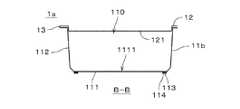
図3は、一のケース本体11を示す底面図である。図2および図3に示すように、ケース本体11は、ケース底部111の下面(すなわち、上下方向においてケース周壁部112とは反対側の主面)において、ケース底部111の中央部1111を避けて外縁に沿って四角環状に配置された粘着層113、および、粘着層113の表面を覆う被覆シート114を備える。被覆シート114も、粘着層113と同様に、ケース底部111の中央部1111を避けるとともに外縁に沿う四角環状とされる。  FIG. 3 is a bottom view showing onecase body 11. As shown in FIGS. 2 and 3, thecase body 11 avoids thecentral portion 1111 of thecase bottom 111 on the lower surface of the case bottom 111 (that is, the main surface opposite to the caseperipheral wall 112 in the vertical direction). A pressure-sensitiveadhesive layer 113 arranged in a square ring shape along the outer edge and a coveringsheet 114 covering the surface of the pressure-sensitiveadhesive layer 113 are provided. Similarly to theadhesive layer 113, thecover sheet 114 is also a quadrangular ring along the outer edge while avoiding thecentral portion 1111 of thecase bottom 111.

図2に示すように、ケース周壁部112は、上方に向かうに従って外側へと向かう(すなわち、ケース底部111から離れるに従ってケース底部111の中心から離れる方向へと向かう)傾斜面とされる。ケース周壁部112は、ケース本体11の外側に向かって突出する薄肉構造である上側凸部1121、および、上側凸部1121とケース底部111との間において上側凸部1121と同様にケース本体11の外側に向かって突出する薄肉構造である下側凸部1122を備える。本実施の形態では、上側凸部1121および下側凸部1122はそれぞれ直線状とされ、ケース周壁部112の全周に亘って設けられる。ケース周壁部112の上端部には、ケース本体11の外側に向かってケース底部111と略平行に(すなわち、水平方向に)広がる鍔部1123が形成されており、鍔部1123もケース周壁部112の全周に亘って設けられる。  As shown in FIG. 2, the caseperipheral wall portion 112 has an inclined surface that goes outward as it goes upward (that is, goes away from the center of thecase bottom portion 111 as it goes away from the case bottom portion 111). The caseperipheral wall portion 112 has anupper convex portion 1121 that is a thin-walled structure protruding toward the outside of the casemain body 11, and between theupper convex portion 1121 and thecase bottom portion 111, similarly to theupper convex portion 1121, The lowerconvex part 1122 which is a thin structure which protrudes toward the outer side is provided. In the present embodiment, theupper convex portion 1121 and thelower convex portion 1122 are each linear, and are provided over the entire circumference of the caseperipheral wall portion 112. An upper end portion of the caseperipheral wall portion 112 is formed with aflange portion 1123 that extends substantially parallel to thecase bottom portion 111 toward the outside of the case main body 11 (that is, in the horizontal direction). Is provided over the entire circumference.

使用前の状態における縫合針ケースセット3では、各ケース本体11の上端部に設けられた鍔部1123と、隣接するケース本体11の上端部に設けられた鍔部1123とが、鍔部1123等に比べて強度の低い弱化線1124(例えば、周囲の部位に比べて樹脂の薄い部分(あるいは、樹脂が存在しない部分)が直線状に断続的に配列されたミシン目)を介して連続している。縫合針ケースセット3では、図1に示すように、8つのケース本体11の間に格子状の弱化線1124が設けられており、看護士等の使用者が、1つのケース本体11および当該ケース本体11に隣接するもう1つのケース本体11を把持し、これら2つのケース本体11の間の部位を弱化線1124に沿って引き裂くように力を作用させることにより、2つのケース本体11が弱化線1124にて分離可能とされる。  In the suture needle case set 3 in a state before use, thecollar 1123 provided at the upper end of eachcase body 11 and thecollar 1123 provided at the upper end of theadjacent case body 11 include thecollar 1123 and the like. The weakeningline 1124 having a lower strength than that of the perforation line (for example, a perforation in which thin portions of the resin (or portions where no resin is present) is intermittently arranged linearly compared to the surrounding portion). Yes. In the suture needle case set 3, as shown in FIG. 1, lattice-like weakening lines 1124 are provided between the eight casemain bodies 11, and a user such as a nurse can use one casemain body 11 and the casemain body 11. By grasping anothercase body 11 adjacent to thebody 11 and applying a force so as to tear the portion between the twocase bodies 11 along theweakening line 1124, the twocase bodies 11 are weakened. At 1124, separation is possible.

縫合針ケースセット3が使用される際には、縫合針ケースセット3から一のケース本体11が弱化線1124に沿って分離され、当該ケース本体11のケース底部111の図3に示す被覆シート114が粘着層113から剥離されてケース本体11が粘着層113により所定の位置に粘着される。ケース本体11は、例えば、手術の一の段階(例えば、閉腹段階)にて使用される予定の複数の縫合針のセット(以下、「縫合針セット」という。)が収容されているシート状のパッケージの表面に粘着され、パッケージから取り出されて使用された後の縫合針が、当該パッケージに粘着されているケース本体11内に上部開口110を介して入れられる。  When the suture needle case set 3 is used, onecase body 11 is separated from the suture needle case set 3 along theweakening line 1124, and thecovering sheet 114 shown in FIG. Is peeled from theadhesive layer 113 and the casemain body 11 is adhered to a predetermined position by theadhesive layer 113. Thecase body 11 is, for example, a sheet shape in which a plurality of sets of suture needles (hereinafter referred to as “suture needle sets”) scheduled to be used in one stage of surgery (for example, the abdominal stage) is accommodated. The suture needle that is adhered to the surface of the package and removed from the package and used is put into the casemain body 11 adhered to the package through theupper opening 110.

ケース本体11が粘着されたパッケージの縫合針の使用が終了し、使用済みの縫合針が全てケース本体11に収容されると、縫合針ケースセット3からもう1つのケース本体が弱化線1124に沿って分離される。そして、図4.Aに示すように、もう1つのケース本体(以下、「ケース本体11a」という。)のケース底部111が、内部に使用済みの縫合針が収容されたケース本体11の上部開口110に重ねられ、上側のケース本体11aが下側のケース本体11に向けて押圧される。なお、図4.Aにおいては、ケース本体11内の縫合針の図示を省略している(図4.Bにおいても同様)。  When the use of the suture needle of the package to which the casemain body 11 is adhered is finished and all the used suture needles are accommodated in the casemain body 11, another case main body extends along theweakening line 1124 from the suture needle case set 3. Separated. And FIG. As shown in A, thecase bottom 111 of another case body (hereinafter referred to as “case body 11a”) is overlaid on theupper opening 110 of thecase body 11 in which a used suture needle is housed. Theupper case body 11 a is pressed toward thelower case body 11. Note that FIG. In A, the illustration of the suture needle in the casemain body 11 is omitted (the same applies to FIG. 4.B).

これにより、ケース本体11のケース周壁部112、並びに、ケース本体11aのケース底部111およびケース周壁部112が弾性変形し、図4.Bに示すように、ケース本体11のケース周壁部112の上側凸部1121の内側の凹部に、ケース本体11aのケース周壁部112の下側凸部1122が嵌合してケース本体11aがケース本体11に固定される。ケース本体11の上部開口110は、ケース本体11に押し込まれて固定されたケース本体11aにより閉塞され、使用済みの縫合針がケース本体11の内部に収容される。換言すれば、ケース本体11およびケース本体11aは、使用済みの縫合針を収容する縫合針ケースであり、上側のケース本体11aは、下側のケース本体11の上部開口110を閉塞する蓋部となっている。以下の説明では、ケース本体11およびケース本体11aを合わせて「縫合針ケース1」と呼ぶ。  As a result, the caseperipheral wall 112 of the casemain body 11 and thecase bottom 111 and the caseperipheral wall 112 of the casemain body 11a are elastically deformed. As shown in B, the lowerconvex portion 1122 of the caseperipheral wall portion 112 of the casemain body 11a is fitted into the concave portion inside the upperconvex portion 1121 of the caseperipheral wall portion 112 of the casemain body 11 so that the casemain body 11a becomes the case main body. 11 is fixed. Theupper opening 110 of the casemain body 11 is closed by a casemain body 11 a that is pushed into the casemain body 11 and fixed, and a used suture needle is accommodated inside the casemain body 11. In other words, the casemain body 11 and the casemain body 11a are suturing needle cases for storing used suturing needles, and the upper casemain body 11a has a lid portion that closes theupper opening 110 of the lower casemain body 11. It has become. In the following description, the casemain body 11 and the casemain body 11a are collectively referred to as “suture needle case 1”.

ケース本体11の上部開口110がケース本体11aにより閉塞されると、看護士により、ケース本体11内の使用済みの縫合針が、蓋部であるケース本体11aのケース底部111の一部である中央部1111(すなわち、粘着層113および被覆シート114が設けられておらず、透光性を有する透光部となっている部位)を介して視認されて計数される。そして、縫合針ケース1の内部に収容された使用済みの縫合針、および、縫合針ケース1が粘着されたパッケージ内の未使用の縫合針の合計個数が、使用前のパッケージに予め収容されていた縫合針の個数(すなわち、手術開始前の状態におけるパッケージ内の縫合針の個数)と比較され、両個数が等しければ、使用済みの縫合針の回収確認作業が終了する。なお、パッケージに予め収容されていた全ての縫合針が使用された場合は、パッケージ内の未使用の針の個数は0本である。  When theupper opening 110 of the casemain body 11 is closed by the casemain body 11a, the nurse uses the used suture needle in the casemain body 11 as a part of thecase bottom 111 of the casemain body 11a as a lid. It is visually recognized through the part 1111 (that is, the part which is not provided with theadhesive layer 113 and thecovering sheet 114 and is a translucent part having translucency) and counted. The total number of used suturing needles housed in thesuturing needle case 1 and unused suturing needles in the package to which thesuturing needle case 1 is adhered is previously housed in the package before use. The number of suture needles (that is, the number of suture needles in the package before the start of surgery) is compared. If the two numbers are equal, the operation for confirming the collection of used suture needles is completed. When all the suture needles previously stored in the package are used, the number of unused needles in the package is zero.

以上に説明したように、縫合針ケース1では、使用済みの縫合針が収容されたケース本体11の上部開口110がケース本体11aにより閉塞されることにより、使用済みの縫合針がケース本体11から外部に飛び出してしまうことが防止される。また、縫合針をスポンジ等に刺して固定する場合と異なり、持針器(ラチェット)による縫合針の把持をケース本体11上にて解除するのみにて縫合針をケース本体11に入れて容易に回収することができるとともに、回収された縫合針の先端が露出して(例えば、スポンジ等を貫通して)使用者の手等を傷つけることが防止される。さらに、縫合針ケース1では、蓋部であるケース本体11aのケース底部111の中央部1111が、縫合針ケース1の内部に収容された使用済みの縫合針を計数するための透光性を有する透光部とされる。これにより、縫合針ケース1に収容された使用済みの縫合針の計数を安全かつ正確に行うことができる。  As described above, in thesuture needle case 1, theupper opening 110 of thecase body 11 in which the used suture needle is accommodated is closed by thecase body 11 a, so that the used suture needle is removed from thecase body 11. Jumping out is prevented. In addition, unlike the case where the suture needle is stabbed into a sponge or the like and fixed, the suture needle can be easily put into thecase body 11 simply by releasing the holding of the suture needle by the needle holder (ratchet) on thecase body 11. While being able to collect | recover, it is prevented that the front-end | tip of the collect | recovered suturing needle is exposed (for example, penetrates sponge etc.) and a user's hand etc. are damaged. Further, in thesuture needle case 1, thecentral portion 1111 of thecase bottom 111 of the casemain body 11 a that is a lid has a light-transmitting property for counting used suture needles housed in thesuture needle case 1. It is set as a translucent part. Thereby, the used suture needles accommodated in thesuture needle case 1 can be counted safely and accurately.

縫合針ケース1では、ケース本体11のケース底部111の上面(内面)のおよそ全面に亘って底部凹凸構造1112が形成されることにより、血液等により濡れている縫合針とケース底部111との接触面積を小さくし、縫合針がケース底部111に強く貼り付いてしまうことを防止することができる。さらに、縫合針ケース1では、上述のように、ケース本体11の上部開口110が蓋部であるケース本体11aにより閉塞されているため、縫合針がケース本体11から飛び出してしまうことを防止しつつ安全に縫合針ケース1を(例えば、縫合針セットのパッケージと共に)揺することができ、縫合針ケース1を揺することにより、ケース底部111上において近接して互いに重なったり貼り付いている複数の縫合針を容易に離間させることができる。その結果、縫合針ケース1の内部に収容された複数の縫合針の計数をより正確に行うことができる。  In thesuture needle case 1, the bottomuneven structure 1112 is formed over substantially the entire upper surface (inner surface) of thecase bottom 111 of the casemain body 11, so that the suture needle wet with blood or the like and the case bottom 111 are in contact with each other. The area can be reduced and the suture needle can be prevented from sticking strongly to thecase bottom 111. Furthermore, in thesuturing needle case 1, as described above, theupper opening 110 of the casemain body 11 is closed by the casemain body 11a which is a lid, so that the suturing needle is prevented from jumping out of the casemain body 11. Thesuture needle case 1 can be safely shaken (for example, together with the package of the suture needle set), and by shaking thesuture needle case 1, a plurality of suture needles that are close to each other on thecase bottom 111 and are overlapped or stuck together Can be easily separated. As a result, a plurality of suture needles housed inside thesuture needle case 1 can be counted more accurately.

ケース本体11では、底部凹凸構造1112の一の方向(図2の奥行方向)に垂直な断面の形状が一定とされることにより、ケース底部111の構造を簡素化しつつ、図5に示すように、略円弧状の縫合針9をケース底部111上において底部凹凸構造1112の凸部に接触させることができる。これにより、縫合針9がケース底部111に強く貼り付いてしまうことをより確実に防止することができるとともに、縫合針ケース1を揺すって複数の縫合針9をより容易に離間させることができる。その結果、縫合針ケース1内の複数の縫合針9の計数をさらに正確に行うことができる。  In the casemain body 11, the structure of thecase bottom 111 is simplified while the shape of the cross section perpendicular to one direction (the depth direction in FIG. 2) of the bottomuneven structure 1112 is made constant, as shown in FIG. The substantially arcuate suture needle 9 can be brought into contact with the convex portion of the bottomuneven structure 1112 on the casebottom portion 111. Accordingly, it is possible to more reliably prevent the suture needle 9 from sticking strongly to thecase bottom 111, and it is possible to more easily separate the plurality of suture needles 9 by shaking thesuture needle case 1. As a result, the plurality of suture needles 9 in thesuture needle case 1 can be counted more accurately.

ケース本体11では、底部凹凸構造1112の最小繰り返しピッチ(すなわち、隣接する2つの凸部の頂部の間の最小距離)が、縫合針ケース1に収容される縫合針の最小曲率半径の4倍以下とされ、底部凹凸構造1112の高さが縫合針の最小曲率半径以下とされることにより、縫合針が底部凹凸構造1112の隣接する2つの凸部の間に嵌り込むことが防止される。また、縫合針が凸部の斜面に沿う姿勢にて凹部に位置したり凸部に跨るような姿勢を取る場合であっても、縫合針の一部が底部凹凸構造1112から離間する。このように、縫合針ケース1内にて任意の姿勢を取る縫合針の一部が底部凹凸構造1112から離間することにより、縫合針ケース1を揺すって縫合針ケース1内の縫合針を容易に移動することができ、複数の縫合針をさらに容易に離間させることができる。なお、縫合針ケース1内にて任意の姿勢を取る縫合針の一部が底部凹凸構造1112から離間するのであれば、底部凹凸構造1112の最小繰り返しピッチや高さは上記範囲外においても様々に変更されてよい(後述する縫合針ケース1aにおいても同様)。  In thecase body 11, the minimum repeat pitch of the bottom uneven structure 1112 (that is, the minimum distance between the tops of two adjacent convex portions) is 4 times or less the minimum curvature radius of the suture needle accommodated in thesuture needle case 1. By setting the height of the bottomuneven structure 1112 to be equal to or less than the minimum curvature radius of the suture needle, the suture needle is prevented from being fitted between two adjacent convex parts of the bottomuneven structure 1112. In addition, even when the suturing needle is positioned in the concave portion or straddling the convex portion in a posture along the slope of the convex portion, a part of the suturing needle is separated from the bottomuneven structure 1112. As described above, a part of the suturing needle taking an arbitrary posture in thesuturing needle case 1 is separated from the bottomuneven structure 1112, so that thesuturing needle case 1 can be easily shaken to easily move the suturing needle in thesuturing needle case 1. The plurality of suture needles can be separated more easily. If a part of the suturing needle that takes an arbitrary posture within thesuturing needle case 1 is separated from the bottomuneven structure 1112, the minimum repetition pitch and height of the bottomuneven structure 1112 may be varied outside the above range. It may be changed (the same applies to thesuture needle case 1a described later).

縫合針ケース1では、底部凹凸構造1112の最小繰り返しピッチが1mm以上とされることにより、ケース底部111を介しての縫合針ケース1内部の視認性が維持される。これにより、縫合針ケース1を縫合針セットのパッケージ等から剥離してケース底部111側から縫合針の計数を行う場合であっても、縫合針の計数を正確に行うことができる。また、底部凹凸構造1112の高さを0.5mm以上とすることにより、底部凹凸構造1112を容易に形成することができる。  In thesuture needle case 1, the minimum repeat pitch of the bottomuneven structure 1112 is set to 1 mm or more, so that the visibility inside thesuture needle case 1 through thecase bottom 111 is maintained. Thereby, even when thesuture needle case 1 is peeled from the package of the suture needle set and the suture needle is counted from the case bottom 111 side, the suture needle can be counted accurately. Moreover, the bottomuneven structure 1112 can be easily formed by setting the height of the bottomuneven structure 1112 to 0.5 mm or more.

上述のように、縫合針ケース1に使用済みの縫合針を収容する際には、縫合針ケース1の上部開口110を閉塞する蓋部として、ケース本体11と同様の構造を有するケース本体11aが利用される。このように、縫合針ケース1の使用時に、2つのケース本体を区別することなく、どちらか一方のケース本体に使用済みの縫合針を入れて他方のケース本体を蓋部とすることができるため、縫合針を縫合針ケース1内に迅速に収容することができる。また、ケース本体11およびケース本体11aの構造を同様とすることにより、ケース本体11およびケース本体11aの製造に必要な金型や被覆シート114の形状、粘着層113の形成機構等を共通化し、縫合針ケース1の制作コストを削減することができる。  As described above, when the used suture needle is accommodated in thesuture needle case 1, the casemain body 11 a having the same structure as the casemain body 11 is used as a lid for closing theupper opening 110 of thesuture needle case 1. Used. Thus, when thesuture needle case 1 is used, the used case needle can be inserted into one of the case bodies and the other case body can be used as a lid without distinguishing between the two case bodies. The suture needle can be quickly accommodated in thesuture needle case 1. In addition, by making the structure of thecase body 11 and thecase body 11a the same, the shape of the mold and thecovering sheet 114 necessary for manufacturing thecase body 11 and thecase body 11a, the formation mechanism of theadhesive layer 113, etc. are shared, The production cost of thesuture needle case 1 can be reduced.

ケース本体11aでは、ケース本体11と同様に、ケース底部111の下面の外周部が、外側に向かうに従って上方に傾斜する傾斜面とされ、ケース周壁部112が、上方に向かうに従って外側へと向かう傾斜面とされる。これにより、ケース本体11aをケース本体11に滑らかに押し込むことができる。また、ケース本体11のケース周壁部112の上側凸部1121とケース本体11aのケース周壁部112の下側凸部1122とが嵌合することにより、ケース本体11aがケース本体11に強固に固定される。その結果、蓋部であるケース本体11aがケース本体11から外れてしまうことが防止され、縫合針ケース1に収容された使用済みの縫合針の計数をより安全に行うことができる。  In the casemain body 11a, similarly to the casemain body 11, the outer peripheral portion of the lower surface of thecase bottom 111 is an inclined surface that is inclined upward as it goes outward, and the caseperipheral wall portion 112 is inclined outward as it goes upward. It is considered a surface. Thereby, the casemain body 11a can be pushed into the casemain body 11 smoothly. In addition, the casemain body 11a is firmly fixed to the casemain body 11 by fitting the upperconvex portion 1121 of the caseperipheral wall portion 112 of the casemain body 11 and the lowerconvex portion 1122 of the caseperipheral wall portion 112 of the casemain body 11a. The As a result, it is possible to prevent the casemain body 11a serving as the lid from being detached from the casemain body 11, and to count the used suture needles accommodated in thesuture needle case 1 more safely.

縫合針ケース1では、ケース本体11aのケース底部111の中央部1111を避けて粘着層113が設けられるため、ケース本体11aのケース底部111の中央部1111が透光部となって、当該透光部を介して縫合針ケース1内の使用済みの縫合針の計数を正確に行うことができる。また、ケース本体11を未使用の縫合針が収容されているパッケージに粘着させることにより、使用済みの縫合針の回収確認作業を容易かつ正確に行うことができるとともに、ケース本体11に縫合針を入れる際に、ケース本体11に持針器や持針器に把持された縫合針等が接触して比較的軽量のケース本体11が移動してしまうことが防止されるため、縫合針をケース本体11に容易に入れることができる。  In thesuture needle case 1, theadhesive layer 113 is provided so as to avoid thecentral portion 1111 of thecase bottom 111 of the casemain body 11a. Therefore, thecentral portion 1111 of thecase bottom 111 of the casemain body 11a serves as a translucent portion. The used suture needles in thesuture needle case 1 can be accurately counted through the section. In addition, thecase body 11 can be easily and accurately collected by attaching thecase body 11 to a package in which unused suture needles are housed. Since thecase body 11 is prevented from moving due to contact with the needle holder or the suture needle held by the needle holder when thecase body 11 is inserted, the relativelylightweight case body 11 is prevented from moving. 11 easily.

なお、ケース本体11は、必ずしも縫合針のパッケージに粘着される必要はなく、例えば、手術室内において医療用品が載置されるワゴン上に載置された当該パッケージの近傍において、ワゴンの上面に粘着されてもよい。このようにケース本体11が所定の位置に粘着されることにより、ケース本体11に縫合針を入れる際に、持針器や縫合針等との接触によるケース本体11の移動が防止され、縫合針をケース本体11に容易に入れることができる。また、上述のように、ケース本体11のケース底部111の中央部1111を避けて粘着層113が設けられるため、縫合針ケース1を所定の位置から剥離してケース本体11のケース底部111側から縫合針の計数を行う場合であっても、透光部であるケース本体11のケース底部111の中央部1111を介して縫合針の計数を正確に行うことができる。  Thecase body 11 does not necessarily have to be adhered to the suture needle package. For example, thecase body 11 is adhered to the upper surface of the wagon in the vicinity of the package placed on the wagon on which the medical supplies are placed in the operating room. May be. As described above, thecase body 11 is adhered to a predetermined position, so that when the suture needle is inserted into thecase body 11, thecase body 11 is prevented from moving due to contact with a needle holder, a suture needle, or the like. Can be easily put into the casemain body 11. Further, as described above, theadhesive layer 113 is provided so as to avoid thecenter portion 1111 of thecase bottom 111 of the casemain body 11, so that thesuture needle case 1 is peeled off from a predetermined position and the casemain body 11 is separated from the case bottom 111 side. Even when counting the suture needles, the suture needles can be accurately counted through thecentral portion 1111 of thecase bottom 111 of thecase body 11 which is a light transmitting portion.

縫合針ケース1では、ケース本体11およびケース本体11aが樹脂により形成されることにより、縫合針ケース1の製造を簡素化することができる。また、ケース本体11およびケース本体11aが樹脂シートから成形されることにより、ケース底部111の底部凹凸構造1112、並びに、ケース周壁部112の上側凸部1121および下側凸部1122を容易に設けることができる。縫合針ケースセット3では、ケース本体11および蓋部となるケース本体11aが弱化線1124を介して連続しているため、使用前の縫合針ケース1の取り扱いが容易とされる。  In thesuture needle case 1, the casemain body 11 and the casemain body 11a are formed of resin, whereby the production of thesuture needle case 1 can be simplified. Further, by forming the casemain body 11 and the casemain body 11a from a resin sheet, the bottomuneven structure 1112 of thecase bottom 111 and the upper convex 1121 and the lower convex 1122 of the caseperipheral wall 112 can be easily provided. Can do. In the suture needle case set 3, the casemain body 11 and the casemain body 11a serving as a lid are continuous via theweakening line 1124, so that thesuture needle case 1 before use can be easily handled.

次に、本発明の第2の実施の形態に係る縫合針ケースセットについて説明する。図6は、第2の実施の形態に係る縫合針ケースセット3aの使用前の状態を示す平面図である。縫合針ケースセット3aは、平面視において略矩形の複数(本実施の形態では、4つ)の縫合針ケース1aを備える。複数の縫合針ケース1aは、互いに同様の構造を有する。  Next, a suture needle case set according to the second embodiment of the present invention will be described. FIG. 6 is a plan view showing a state before use of the suturing needle case set 3a according to the second embodiment. The suture needle case set 3a includes a plurality of (four in the present embodiment)suture needle cases 1a that are substantially rectangular in plan view. The plurality ofsuture needle cases 1a have the same structure.

図7は、一の縫合針ケース1aを図6中のB−Bの位置にて切断した断面図である。図7に示すように、縫合針ケース1aは、第1の実施の形態に係るケース本体11(図2参照)と類似の構造を有するケース本体11b、および、ケース本体11bの上部開口110を閉塞する蓋部12を備える。蓋部12は、図7中において下向きに突出するとともに平面視において上部開口110とほぼ同様の形状を有する凸部121を備え、凸部121が上部開口110に嵌合することにより、蓋部12が上部開口110を閉塞しつつケース本体11bに固定される。  FIG. 7 is a cross-sectional view of onesuture needle case 1a cut at the position BB in FIG. As shown in FIG. 7, thesuture needle case 1a closes thecase body 11b having a structure similar to that of the case body 11 (see FIG. 2) according to the first embodiment and theupper opening 110 of thecase body 11b. Thelid portion 12 is provided. Thelid portion 12 includes aconvex portion 121 that protrudes downward in FIG. 7 and has substantially the same shape as theupper opening 110 in a plan view, and theconvex portion 121 is fitted into theupper opening 110, thereby thelid portion 12. Is fixed to thecase body 11 b while closing theupper opening 110.

ケース本体11bは、平面視において略矩形(本実施の形態では、略正方形)のケース底部111、および、ケース底部111の全周を囲むとともにケース底部111から上方に向かって立ち上がるケース周壁部112を備え、ケース周壁部112の上端部の一部と蓋部12の周縁部の一部とが可撓性を有する接続部13により接続されている。本実施の形態では、平面視において略矩形の蓋部12およびケース周壁部112のそれぞれの1つの辺が接続される。ケース本体11b、蓋部12および接続部13の全体は、薄肉の樹脂シートから一体的に成形されている。図7では、図示の都合上、縫合針ケース1aの断面を実線のみにて示す(図8および図9においても同様)。  The casemain body 11b includes a case bottom 111 having a substantially rectangular shape (substantially square in the present embodiment) in plan view, and a caseperipheral wall 112 that surrounds the entire circumference of thecase bottom 111 and rises upward from thecase bottom 111. In addition, a part of the upper end of the caseperipheral wall 112 and a part of the peripheral edge of thelid 12 are connected by a connectingpart 13 having flexibility. In the present embodiment, one side of each of the substantiallyrectangular lid 12 and caseperipheral wall 112 is connected in plan view. The casemain body 11b, thecover part 12, and thewhole connection part 13 are integrally formed from a thin resin sheet. In FIG. 7, for convenience of illustration, the cross section of thesuture needle case 1 a is indicated only by a solid line (the same applies to FIGS. 8 and 9).

蓋部12、並びに、ケース本体11bのケース底部111およびケース周壁部112は、それぞれを介して縫合針ケース1aの内部が視認可能となるように透光性を有する。また、縫合針ケース1aは、第1の実施の形態に係る縫合針ケース1のケース本体11(図3参照)と同様に、ケース本体11bのケース底部111の下面(外面)において、ケース底部111の中央部1111を避けて外縁に沿って四角環状に配置された粘着層113、および、粘着層113の表面を覆う被覆シート114を備える。被覆シート114も、粘着層113と同様に、ケース底部111の中央部1111を避けるとともに外縁に沿う四角環状とされる。  Thelid 12 and thecase bottom 111 and the caseperipheral wall 112 of the casemain body 11b have translucency so that the inside of thesuture needle case 1a can be visually recognized through each of them. In addition, thesuture needle case 1a is similar to the case main body 11 (see FIG. 3) of thesuture needle case 1 according to the first embodiment on the lower surface (outer surface) of thecase bottom 111 of the casemain body 11b. Theadhesive layer 113 disposed in a square ring shape along the outer edge while avoiding thecentral portion 1111, and thecovering sheet 114 covering the surface of theadhesive layer 113 are provided. Similarly to theadhesive layer 113, thecover sheet 114 is also a quadrangular ring along the outer edge while avoiding thecentral portion 1111 of thecase bottom 111.

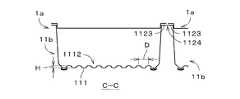
図8は、縫合針ケースセット3aの一部を図6中のC−Cの位置にて切断した部分断面図である。図8に示すように、ケース本体11bでは、第1の実施の形態と同様に、ケース底部111の上面および下面(内面および外面)のおよそ全面に亘って底部凹凸構造1112が形成されており、底部凹凸構造1112は、図8の奥行方向に垂直な断面の形状が一定である。図8中において符号Dを付して示す底部凹凸構造1112の最小繰り返しピッチは、1mm以上、かつ、縫合針ケース1aに収容される縫合針の最小曲率半径の4倍以下とされる。また、図8中において符号Hを付して示す底部凹凸構造1112の高さは、0.5mm以上、かつ、ケース本体11に収容される縫合針の最小曲率半径以下とされる。  FIG. 8 is a partial cross-sectional view of a portion of the suture needle case set 3a cut at the position CC in FIG. As shown in FIG. 8, in thecase body 11b, the bottomuneven structure 1112 is formed over substantially the entire upper surface and lower surface (inner surface and outer surface) of the casebottom portion 111, as in the first embodiment. The bottomuneven structure 1112 has a constant cross-sectional shape perpendicular to the depth direction in FIG. The minimum repetitive pitch of the bottomuneven structure 1112 indicated by reference sign D in FIG. 8 is 1 mm or more and 4 times or less the minimum curvature radius of the suture needle accommodated in thesuture needle case 1a. Further, the height of the bottom concavo-convex structure 1112 indicated by reference sign H in FIG. 8 is 0.5 mm or more and not more than the minimum curvature radius of the suture needle accommodated in the casemain body 11.

使用前の状態における縫合針ケースセット3aでは、各ケース本体11bの上端部に設けられた鍔部1123と、隣接するケース本体11bの上端部に設けられた鍔部1123とが、鍔部1123等に比べて強度の低い弱化線1124を介して連続している。縫合針ケースセット3aでは、看護士等の使用者が、1つの縫合針ケース1aおよび当該縫合針ケース1aに隣接するもう1つの縫合針ケース1aを把持し、これら2つの縫合針ケース1aの間の部位を弱化線1124に沿って引き裂くように力を作用させることにより、2つの縫合針ケース1aが弱化線1124にて分離可能とされる。縫合針ケースセット3aでは、複数の縫合針ケース1aの蓋部12同士が弱化線を介して連続する構造とされてもよい。  In the suture needle case set 3a in a state before use, thecollar portion 1123 provided at the upper end portion of eachcase body 11b and thecollar portion 1123 provided at the upper end portion of theadjacent case body 11b include thecollar portion 1123 and the like. It continues through theweakening line 1124, which is lower in strength. In the suture needle case set 3a, a user such as a nurse holds onesuture needle case 1a and anothersuture needle case 1a adjacent to thesuture needle case 1a, and between these twosuture needle cases 1a. The twosuture needle cases 1a can be separated by theweakening line 1124 by applying a force so as to tear the part of the two along theweakening line 1124. The suture needle case set 3a may have a structure in which thelid portions 12 of the plurality ofsuture needle cases 1a are continuous via weakening lines.

縫合針ケースセット3aが使用される際には、縫合針ケースセット3aから一の縫合針ケース1aが弱化線1124に沿って分離され、図9に示すように、蓋部12の凸部121がケース本体11bの上部開口110から離間した状態(すなわち、ケース本体11bの上部開口110が開放された状態)で、当該縫合針ケース1aのケース底部111の被覆シート114が粘着層113から剥離されて縫合針ケース1aが粘着層113により所定の位置に粘着される。縫合針ケース1aは、例えば、手術の一の段階にて使用される予定の縫合針セットが収容されているシート状のパッケージの表面に粘着され、パッケージから取り出されて使用された後の縫合針が、当該パッケージに粘着されている縫合針ケース1a内に上部開口110を介して入れられる。  When the suture needle case set 3a is used, onesuture needle case 1a is separated from the suture needle case set 3a along theweakening line 1124. As shown in FIG. In a state of being separated from theupper opening 110 of the casemain body 11b (that is, in a state where theupper opening 110 of the casemain body 11b is opened), thecovering sheet 114 of thecase bottom 111 of thesuture needle case 1a is peeled off from theadhesive layer 113. Thesuture needle case 1a is adhered to a predetermined position by theadhesive layer 113. Thesuturing needle case 1a is, for example, adhered to the surface of a sheet-like package in which a suturing needle set scheduled to be used in one stage of surgery is accommodated, removed from the package and used. Is inserted into thesuture needle case 1a adhered to the package via theupper opening 110.

縫合針ケース1aでは、ケース本体11bの上部開口110が開放されている状態において、蓋部12の接続部13とは反対側の端部122が、ケース本体11bが載置される水平方向に広がる平坦な載置面9に当接する。これにより、ケース本体11bが粘着層113により粘着されていない場合であっても、ケース本体11bのケース底部111(より具体的には、ケース底部111の底部凹凸構造1112の上下方向の中心を通る面)が載置面(すなわち、水平方向)におよそ平行とされ、縫合針ケース1aが蓋部12の重さにより傾いて縫合針が縫合針ケース1aに入れにくくなることが防止される。また、蓋部12の開閉時に折り曲げられる接続部13が、上部開口110が開放されている状態において下向きに突出するU字状とされることにより、図9に示すように、ケース本体11bの側方において上部開口110に固定されていない蓋部12が上部開口110から斜め下方に向かう縫合針ケース1aを容易に成形することができる。  In thesuture needle case 1a, in the state where theupper opening 110 of the casemain body 11b is opened, theend 122 on the opposite side of theconnection portion 13 of thelid 12 spreads in the horizontal direction on which the casemain body 11b is placed. It contacts the flat mounting surface 9. Thereby, even when the casemain body 11b is not adhered by theadhesive layer 113, thecase bottom 111 of the casemain body 11b (more specifically, the center of the bottomuneven structure 1112 of the case bottom 111 passes through the center in the vertical direction). The surface) is approximately parallel to the placement surface (that is, the horizontal direction), and thesuturing needle case 1a is prevented from being inclined due to the weight of thelid portion 12 so that the suturing needle is difficult to enter thesuturing needle case 1a. Further, theconnection portion 13 that is bent when thelid portion 12 is opened and closed is formed in a U shape that protrudes downward in a state where theupper opening 110 is opened, so that the side of the casemain body 11b as shown in FIG. On the other hand, thesuture needle case 1a in which thelid portion 12 that is not fixed to theupper opening 110 is directed obliquely downward from theupper opening 110 can be easily formed.

縫合針ケース1aが粘着されたパッケージ内の縫合針の使用が終了し、当該パッケージから取り出されて使用された使用済みの縫合針が全て縫合針ケース1aのケース本体11bに収容されると、図7に示すように、ケース本体11bの上部開口110が蓋部12により閉塞される。続いて、看護士により、縫合針ケース1a内の使用済みの縫合針が、蓋部12を介して視認されて計数される。さらに、縫合針ケース1aの内部に収容された使用済みの縫合針、および、縫合針ケース1aが粘着されたパッケージ内の未使用の縫合針の合計個数が、パッケージに予め収容されていた縫合針の個数と比較され、両個数が等しければ、使用済みの縫合針の回収確認作業が終了する。  When the use of the suturing needle in the package to which thesuturing needle case 1a is adhered is finished and all used suturing needles taken out from the package and used are accommodated in thecase body 11b of thesuturing needle case 1a, FIG. As shown in FIG. 7, theupper opening 110 of thecase body 11 b is closed by thelid portion 12. Subsequently, the used suture needle in thesuture needle case 1a is visually recognized through thelid 12 and counted by the nurse. Furthermore, the total number of used suturing needles accommodated in thesuturing needle case 1a and unused suturing needles in the package to which thesuturing needle case 1a is adhered is preliminarily accommodated in the package. If the two numbers are equal to each other, the collection confirmation operation for the used suture needle is completed.

以上に説明したように、縫合針ケース1aでは、第1の実施の形態と同様に、ケース本体11bの上部開口110が蓋部12により閉塞されることにより、使用済みの縫合針が縫合針ケース1aから外部に飛び出してしまうことが防止される。また、縫合針をスポンジ等に刺して固定する場合と異なり、縫合針をケース本体11bに入れて容易に回収することができるとともに、回収された縫合針の先端により使用者の手等を傷つけることが防止される。さらに、縫合針ケース1aでは、蓋部12のほぼ全体が、縫合針ケース1aの内部に収容された使用済みの縫合針を計数するための透光性を有する透光部とされる。これにより、縫合針ケース1aに収容された使用済みの縫合針の計数を安全かつ正確に行うことができる。  As described above, in thesuture needle case 1a, as in the first embodiment, theupper opening 110 of thecase body 11b is closed by thelid 12, so that the used suture needle can be replaced with the suture needle case. Jumping out from 1a to the outside is prevented. In addition, unlike the case where the suture needle is inserted into a sponge or the like and fixed, the suture needle can be easily collected by putting it in thecase body 11b, and the user's hand or the like is damaged by the tip of the collected suture needle. Is prevented. Further, in thesuturing needle case 1a, almost theentire lid portion 12 is a translucent portion having translucency for counting used suturing needles housed in thesuturing needle case 1a. Thereby, the used suture needle accommodated in thesuture needle case 1a can be counted safely and accurately.

縫合針ケース1aでは、第1の実施の形態と同様に、ケース底部111の上面のおよそ全面に亘って底部凹凸構造1112が形成されることにより、血液等により濡れている縫合針がケース底部111に強く貼り付いてしまうことを防止することができる。さらに、縫合針ケース1aでは、ケース本体11bの上部開口110が蓋部12により閉塞されているため、縫合針ケース1aを揺することにより、ケース底部111上において近接して互いに重なったり貼り付いている複数の縫合針を容易に離間させ、縫合針ケース1aの内部に収容された複数の縫合針の計数をより正確に行うことができる。  In thesuture needle case 1a, as in the first embodiment, the bottomuneven structure 1112 is formed over almost the entire top surface of thecase bottom 111, so that the suture needle wetted by blood or the like can be removed from thecase bottom 111. Can be prevented from sticking strongly to the surface. Further, in thesuture needle case 1a, since theupper opening 110 of thecase body 11b is closed by thelid portion 12, thesuture needle case 1a is shaken so as to be close and overlap each other on thecase bottom 111. The plurality of suture needles can be easily separated, and the plurality of suture needles housed in thesuture needle case 1a can be counted more accurately.

ケース本体11bでは、第1の実施の形態と同様に、底部凹凸構造1112の一の方向(図8の奥行方向)に垂直な断面の形状が一定とされることにより、ケース底部111の構造を簡素化しつつ、略円弧状の縫合針を底部凹凸構造1112の凸部に接触させ、縫合針がケース底部111に強く貼り付いてしまうことをより確実に防止することができ、縫合針ケース1aを揺すって複数の縫合針をより容易に離間させることができる。その結果、縫合針ケース1a内の複数の縫合針の計数をさらに正確に行うことができる。  In the casemain body 11b, as in the first embodiment, the shape of the cross section perpendicular to one direction (the depth direction in FIG. 8) of the bottomuneven structure 1112 is made constant, so that the structure of thecase bottom 111 is formed. While simplifying, the substantially arcuate suture needle can be brought into contact with the convex portion of the bottomuneven structure 1112 to more securely prevent the suture needle from sticking strongly to the casebottom portion 111. The plurality of suture needles can be separated more easily by shaking. As a result, a plurality of suture needles in thesuture needle case 1a can be counted more accurately.

また、ケース本体11bでは、第1の実施の形態と同様に、底部凹凸構造1112の最小繰り返しピッチが、縫合針ケース1aに収容される縫合針の最小曲率半径の4倍以下とされ、底部凹凸構造1112の高さが縫合針の最小曲率半径以下とされることにより、縫合針ケース1a内にて任意の姿勢を取る縫合針の一部が底部凹凸構造1112から離間するため、縫合針ケース1aを揺すって縫合針ケース1a内の縫合針を容易に移動することができ、複数の縫合針をさらに容易に離間させることができる。さらに、底部凹凸構造1112の最小繰り返しピッチが1mm以上とされることにより、ケース底部111を介しての縫合針ケース1a内部の視認性が維持され、ケース底部111側からであっても縫合針の計数を正確に行うことができ、底部凹凸構造1112の高さを0.5mm以上とすることにより、底部凹凸構造1112を容易に形成することができる。  Further, in the casemain body 11b, as in the first embodiment, the minimum repetitive pitch of the bottomuneven structure 1112 is not more than four times the minimum radius of curvature of the suture needle accommodated in thesuture needle case 1a. Since the height of thestructure 1112 is equal to or less than the minimum curvature radius of the suture needle, a part of the suture needle taking an arbitrary posture in thesuture needle case 1a is separated from the bottomuneven structure 1112. The suture needles in thesuture needle case 1a can be easily moved by shaking, and the plurality of suture needles can be separated more easily. Further, the minimum repetition pitch of the bottomuneven structure 1112 is set to 1 mm or more, so that the visibility inside thesuture needle case 1a through thecase bottom 111 is maintained, and even from the case bottom 111 side, the suture needle Counting can be performed accurately, and the bottomuneven structure 1112 can be easily formed by setting the height of the bottomuneven structure 1112 to 0.5 mm or more.

第2の実施の形態に係る縫合針ケース1aでは、特に、ケース本体11bと蓋部12とが接続部13により接続されていることにより、縫合針ケース1aの使用時にケース本体11bと蓋部12とを個別に扱う必要がないため、容易かつ迅速にケース本体11bの上部開口110を閉塞することができる。  In thesuturing needle case 1a according to the second embodiment, in particular, the casemain body 11b and thelid portion 12 are used when thesuturing needle case 1a is used because the casemain body 11b and thelid portion 12 are connected by the connectingportion 13. Therefore, theupper opening 110 of thecase body 11b can be closed easily and quickly.

また、第1の実施の形態と同様に、ケース底部111に設けられた粘着層113により縫合針ケース1aを所定の位置に粘着させることにより、縫合針ケース1aに縫合針を入れる際に、ケース本体11bや蓋部12に持針器や持針器に把持された縫合針等が接触して比較的軽量の縫合針ケース1aが移動してしまうことが防止されるため、縫合針を縫合針ケース1aに容易に入れることができる。さらに、縫合針ケース1aを未使用の縫合針が収容されているパッケージに粘着させることにより、使用済みの縫合針の回収確認作業を容易かつ正確に行うことができる。また、上述のように、ケース本体11bのケース底部111の中央部1111を避けて粘着層113が設けられるため、縫合針ケース1aをパッケージ等から剥離してケース底部111側から縫合針の計数を行う場合であっても、縫合針の計数を正確に行うことができる。  Similarly to the first embodiment, when thesuturing needle case 1a is adhered to a predetermined position by theadhesive layer 113 provided on thecase bottom 111, the case is inserted into thesuturing needle case 1a. Since the needle holder, the suture needle gripped by the needle holder, etc. are in contact with themain body 11b and thelid portion 12 and the relatively lightweightsuture needle case 1a is prevented from moving, the suture needle is replaced with the suture needle. It can be easily put in thecase 1a. Further, by attaching thesuture needle case 1a to a package in which an unused suture needle is accommodated, the used suture needle can be easily and accurately checked for collection. Further, as described above, since theadhesive layer 113 is provided avoiding thecentral portion 1111 of thecase bottom 111 of thecase body 11b, thesuture needle case 1a is peeled off from the package or the like, and the number of suture needles is counted from the case bottom 111 side. Even when it is performed, the suture needle can be accurately counted.

縫合針ケース1aでは、ケース本体11bおよび蓋部12が樹脂により一体的に成形されることにより、縫合針ケース1aの製造を簡素化することができる。また、縫合針ケース1aが樹脂シートから成形されることにより、ケース底部111の底部凹凸構造1112を容易に設けることができる。縫合針ケースセット3aでは、複数の縫合針ケース1aが弱化線1124を介して連続しているため、使用前の複数の縫合針ケース1aの取り扱いが容易とされる。  In thesuture needle case 1a, the casemain body 11b and thelid portion 12 are integrally formed of resin, whereby the production of thesuture needle case 1a can be simplified. Further, by forming thesuture needle case 1a from a resin sheet, the bottomuneven structure 1112 of the case bottom 111 can be easily provided. In the suture needle case set 3a, since the plurality ofsuture needle cases 1a are continuous via theweakening line 1124, handling of the plurality ofsuture needle cases 1a before use is facilitated.

以上、本発明の実施の形態について説明してきたが、本発明は上記実施の形態に限定されるものではなく、様々な変更が可能である。  As mentioned above, although embodiment of this invention has been described, this invention is not limited to the said embodiment, A various change is possible.

上記実施の形態に係る縫合針ケースでは、ケース底部111の中央部1111を避けて四角環状の粘着層113が設けられるが、粘着層113は、例えば、中央部1111を避けてケース底部111の4つの角部近傍にのみ設けられてもよい。  In the suturing needle case according to the above-described embodiment, the quadrangular annularadhesive layer 113 is provided to avoid thecentral portion 1111 of thecase bottom 111, but theadhesive layer 113 is, for example, 4 of the case bottom 111 to avoid thecentral portion 1111. It may be provided only near one corner.

第1の実施の形態に係る縫合針ケース1では、ケース本体11およびケース本体11aの双方のケース底部111の中央部1111が透光部とされるが、ケース本体11のケース底部111の一部、または、蓋部であるケース本体11aのケース底部111の一部が透光部となっていればよい。すなわち、ケース本体11のケース底部111および蓋部の少なくとも一部が、縫合針ケース1の内部に収容された縫合針を計数するための透光部となっていればよい。また、第2の実施の形態に係る縫合針ケース1aでも同様に、ケース本体11bのケース底部111の一部、または、蓋部12の一部が透光部となっていればよい。すなわち、ケース本体11bのケース底部111および蓋部12の少なくとも一部が、縫合針ケース1aの内部に収容された縫合針を計数するための透光部となっていればよい。例えば、縫合針ケース1aの蓋部12を介して縫合針の計数が行われる場合には、ケース底部111の下面の全面に亘って粘着層113が設けられ、透光性が低い(または、不透明の)被覆シート114により粘着層113が覆われていてもよい。第1の実施の形態に係る縫合針ケース1でも同様に、ケース本体11のケース底部111の下面の全面に亘って粘着層113が設けられ、透光性が低い(または、不透明の)被覆シート114により粘着層113が覆われていてもよい。  In thesuture needle case 1 according to the first embodiment, thecentral portion 1111 of thecase bottom 111 of both the casemain body 11 and the casemain body 11a is a translucent portion, but a part of thecase bottom 111 of the casemain body 11 is used. Or a part of casebottom part 111 of casemain body 11a which is a cover part should just be a translucent part. That is, it is only necessary that at least a part of thecase bottom 111 and the lid of the casemain body 11 be a translucent part for counting the suture needles housed in thesuture needle case 1. Similarly, in thesuture needle case 1a according to the second embodiment, a part of thecase bottom 111 of the casemain body 11b or a part of thelid 12 may be a translucent part. That is, it is only necessary that at least a part of the casebottom portion 111 and thelid portion 12 of the casemain body 11b be a translucent portion for counting the suture needles housed in thesuture needle case 1a. For example, when the number of suture needles is counted through thelid portion 12 of thesuture needle case 1a, theadhesive layer 113 is provided over the entire lower surface of the casebottom portion 111, and the translucency is low (or opaque). Theadhesive layer 113 may be covered with thecovering sheet 114. Similarly, in thesuture needle case 1 according to the first embodiment, theadhesive layer 113 is provided over the entire lower surface of thecase bottom 111 of the casemain body 11, and the covering sheet having low translucency (or opaqueness) is provided. Theadhesive layer 113 may be covered with 114.

上記実施の形態に係る縫合針ケースでは、ケース底部111の底部凹凸構造1112は、必ずしも一の方向に垂直な断面の形状が一定なものである必要はなく、例えば、ケース底部111の上面のおよそ全面に亘って千鳥状に配置された複数の凸部が設けられてもよく、ケース底部111の上面がおよそ全面に亘って梨地状とされてもよい。また、ケース本体の形状は、平面視において必ずしも略矩形状とされる必要はなく、他の様々な形状とされてよい。  In the suture needle case according to the above embodiment, the bottomuneven structure 1112 of thecase bottom 111 does not necessarily have a constant cross-sectional shape perpendicular to one direction. A plurality of convex portions arranged in a zigzag manner may be provided over the entire surface, and the upper surface of the casebottom portion 111 may be formed into a satin finish over substantially the entire surface. Further, the shape of the case main body does not necessarily have to be a substantially rectangular shape in plan view, and may be various other shapes.

第1の実施の形態に係る縫合針ケースセットの平面図である。It is a top view of the suturing needle case set concerning a 1st embodiment.縫合針ケースセットの部分断面図である。It is a fragmentary sectional view of a suture needle case set.ケース本体の底面図である。It is a bottom view of a case body.縫合針ケースの断面図である。It is sectional drawing of a suture needle case.縫合針ケースの断面図である。It is sectional drawing of a suture needle case.縫合針ケースの断面図である。It is sectional drawing of a suture needle case.第2の実施の形態に係る縫合針ケースセットの平面図である。It is a top view of the suturing needle case set which concerns on 2nd Embodiment.縫合針ケースの断面図である。It is sectional drawing of a suture needle case.縫合針ケースセットの部分断面図である。It is a fragmentary sectional view of a suture needle case set.縫合針ケースの断面図である。It is sectional drawing of a suture needle case.

符号の説明Explanation of symbols

1,1a 縫合針ケース
3,3a 縫合針ケースセット
11,11a,11b ケース本体
12 蓋部
13 接続部
110 上部開口
111 ケース底部
112 ケース周壁部
113 粘着層
114 被覆シート
1111 中央部
1112 底部凹凸構造
1124 弱化線
DESCRIPTION OFSYMBOLS 1,1aSuture needle case 3,3a Suture needle case set 11, 11a, 11b Casemain body 12Lid part 13Connection part 110Upper opening 111 Casebottom part 112 Case surroundingwall part 113Adhesive layer 114Cover sheet 1111Center part 1112 Bottomuneven structure 1124 Weakening line

Claims (8)

Translated fromJapanese
使用済みの手術用縫合針を収容する縫合針ケースであって、
ケース底部と前記ケース底部の全周を囲むケース周壁部とを有するケース本体と、
前記ケース本体の上部開口を閉塞する蓋部と、
を備え、
前記ケース底部および前記蓋部の少なくとも一部が、内部に収容された手術用縫合針を計数するための透光性を有する透光部となっており、
前記ケース底部の内面のおよそ全面に亘って凹凸構造が形成されており、
縫合針が収容される場合に前記縫合針の一部が前記凹凸構造と離間することを特徴とする縫合針ケース。
A suturing needle case for accommodating a used surgical suturing needle,
A case body having a case bottom and a case peripheral wall surrounding the entire circumference of the case bottom;
A lid for closing the upper opening of the case body;
With
At least a part of the case bottom and the lid is a translucent part having translucency for counting the surgical suture needles housed therein,
A concavo-convex structure is formed over substantially the entire inner surface of the case bottom,
A suturing needle case, wherein a part of the suturing needle is separated from the concavo-convex structure when the suturing needle is accommodated .
請求項1に記載の縫合針ケースであって、
前記ケース本体が、樹脂シートから成形されることを特徴とする縫合針ケース。
The suturing needle case according to claim 1,
A suturing needle case, wherein the case body is formed from a resin sheet.
請求項1に記載の縫合針ケースであって、
前記蓋部の周縁部の一部と前記ケース周壁部の上端部の一部とが可撓性を有する接続部にて接続されていることを特徴とする縫合針ケース。
The suturing needle case according to claim 1,
A suture needle case, wherein a part of a peripheral edge of the lid part and a part of an upper end part of the case peripheral wall part are connected by a flexible connecting part.
請求項に記載の縫合針ケースであって、
前記蓋部および前記ケース本体の全体が樹脂により一体的に成形されていることを特徴とする縫合針ケース。
The suturing needle case according to claim3 ,
A suturing needle case, wherein the lid and the entire case body are integrally formed of resin.
請求項に記載の縫合針ケースであって、
前記蓋部および前記ケース本体が、樹脂シートから成形されることを特徴とする縫合針ケース。
The suturing needle case according to claim4 ,
A suture needle case, wherein the lid and the case main body are molded from a resin sheet.
使用済みの手術用縫合針を収容する縫合針ケースであって、
ケース底部と前記ケース底部の全周を囲むケース周壁部とを有するケース本体と、
前記ケース本体の上部開口を閉塞する蓋部と、
を備え、
前記ケース底部および前記蓋部の少なくとも一部が、内部に収容された手術用縫合針を計数するための透光性を有する透光部となっており、
前記ケース底部の内面のおよそ全面に亘って凹凸構造が形成されており、
前記蓋部が、前記ケース本体と同様の構造を有するもう1つのケース本体であり、
前記もう1つのケース本体のケース底部を前記ケース本体の前記上部開口に重ねて前記もう1つのケース本体を前記ケース本体に向かって押圧することにより、前記上部開口が閉塞されることを特徴とする縫合針ケース。
A suturing needle case for accommodating a used surgical suturing needle,
A case body having a case bottom and a case peripheral wall surrounding the entire circumference of the case bottom;
A lid for closing the upper opening of the case body;
With
At least a part of the case bottom and the lid is a translucent part having translucency for counting the surgical suture needles housed therein,
A concavo-convex structure is formed over substantially the entire inner surface of the case bottom,
The lid is another case body having the same structure as the case body;
The upper opening is closed by putting the case bottom of the other case body over the upper opening of the case body and pressing the other case body toward the case body. Suture needle case.
請求項に記載の縫合針ケースであって、
前記ケース本体が、樹脂シートから成形されることを特徴とする縫合針ケース。
The suturing needle case according to claim6 ,
A suturing needle case, wherein the case body is formed from a resin sheet.
請求項1ないし7のいずれかに記載の縫合針ケースであって、
前記凹凸構造の一の方向に垂直な断面の形状が一定であることを特徴とする縫合針ケース。
The suturing needle case according toany one of claims 1to 7 ,
A suturing needle case having a constant cross-sectional shape perpendicular to one direction of the concavo-convex structure.
JP2008335643A2008-12-292008-12-29 Suture needle caseActiveJP5424455B2 (en)

Priority Applications (1)

Application NumberPriority DateFiling DateTitle
JP2008335643AJP5424455B2 (en)2008-12-292008-12-29 Suture needle case

Applications Claiming Priority (1)

Application NumberPriority DateFiling DateTitle
JP2008335643AJP5424455B2 (en)2008-12-292008-12-29 Suture needle case

Publications (2)

Publication NumberPublication Date
JP2010154989A JP2010154989A (en)2010-07-15
JP5424455B2true JP5424455B2 (en)2014-02-26

Family

ID=42573355

Family Applications (1)

Application NumberTitlePriority DateFiling Date
JP2008335643AActiveJP5424455B2 (en)2008-12-292008-12-29 Suture needle case

Country Status (1)

CountryLink
JP (1)JP5424455B2 (en)

Family Cites Families (4)

* Cited by examiner, † Cited by third party
Publication numberPriority datePublication dateAssigneeTitle
US4013109B1 (en)*1975-08-221995-04-25Dan SandelDisposable container for surgical instruments.
WO1996007364A1 (en)*1994-09-051996-03-14Stephen Gilbert DuncanTray and disposable liner therefor
JP3705416B2 (en)*1999-07-212005-10-12小関医科株式会社 Surgical needle counter
US20040129591A1 (en)*2000-10-022004-07-08Tomoaki KosekiOperation sutural needle counter

Also Published As

Publication numberPublication date
JP2010154989A (en)2010-07-15

Similar Documents

PublicationPublication DateTitle
EP1293222A1 (en)Packaging for blood collection set with button-actuated safety shield
TW202106238A (en)Implantation device for biosensor capable of automatically completing needle implantation and needle withdrawal within 100 milliseconds
JP6853413B2 (en) Sensor insertion device
JP2006518629A (en) Medical instrument package that opens automatically and method of manufacturing the same
JP5424454B2 (en) Suture needle case set
EP0904731A2 (en)30 Gauge Lancet
KR20020046219A (en)Container for holding therein needles used in surgical operation, containing instrument for holding therein needles, and picking device for use in containing needles
JP5424455B2 (en) Suture needle case
JP4171478B2 (en) Endoscope plug
JP2006507070A (en) Puncture prevention device for bent needles
JP2008043774A (en) Endoscope plug
KR20160053701A (en)Dental impression tray
JP2013189241A (en)Storage container, and method for use of the same
CN100346502C (en)Product dispenser
JP2022551281A (en) surgical sharps storage system
WO2009125837A1 (en)Device for maintaining negative pressure under skin
JP5930688B2 (en) Lancet cartridge
JP2009247834A (en)Storage container of surgical suture needle
JP5052092B2 (en) Cotton swab packaging container
JP3702954B2 (en) Storage container for used surgical needle and surgical needle gripping instrument
JP5013600B2 (en) Container for medical device
JP2018029894A (en)Medical equipment and fixture
JP2017099519A (en) Guide wire insertion aid
JP4801561B2 (en) Medical needle puller
JP6528423B2 (en) Transdermal administration device, and transdermal administration device container

Legal Events

DateCodeTitleDescription
A621Written request for application examination

Free format text:JAPANESE INTERMEDIATE CODE: A621

Effective date:20111201

A977Report on retrieval

Free format text:JAPANESE INTERMEDIATE CODE: A971007

Effective date:20130328

A131Notification of reasons for refusal

Free format text:JAPANESE INTERMEDIATE CODE: A131

Effective date:20130408

TRDDDecision of grant or rejection written
A01Written decision to grant a patent or to grant a registration (utility model)

Free format text:JAPANESE INTERMEDIATE CODE: A01

Effective date:20131121

A61First payment of annual fees (during grant procedure)

Free format text:JAPANESE INTERMEDIATE CODE: A61

Effective date:20131125

R150Certificate of patent or registration of utility model

Free format text:JAPANESE INTERMEDIATE CODE: R150

Ref document number:5424455

Country of ref document:JP

Free format text:JAPANESE INTERMEDIATE CODE: R150

R250Receipt of annual fees

Free format text:JAPANESE INTERMEDIATE CODE: R250

R250Receipt of annual fees

Free format text:JAPANESE INTERMEDIATE CODE: R250

R250Receipt of annual fees

Free format text:JAPANESE INTERMEDIATE CODE: R250

R250Receipt of annual fees

Free format text:JAPANESE INTERMEDIATE CODE: R250

R250Receipt of annual fees

Free format text:JAPANESE INTERMEDIATE CODE: R250

R250Receipt of annual fees

Free format text:JAPANESE INTERMEDIATE CODE: R250

R250Receipt of annual fees

Free format text:JAPANESE INTERMEDIATE CODE: R250

R250Receipt of annual fees

Free format text:JAPANESE INTERMEDIATE CODE: R250

R250Receipt of annual fees

Free format text:JAPANESE INTERMEDIATE CODE: R250


[8]ページ先頭

©2009-2025 Movatter.jp