JP5423988B2 - Keyless entry system for vehicles - Google Patents
Keyless entry system for vehiclesDownload PDFInfo
- Publication number
- JP5423988B2 JP5423988B2JP2010253546AJP2010253546AJP5423988B2JP 5423988 B2JP5423988 B2JP 5423988B2JP 2010253546 AJP2010253546 AJP 2010253546AJP 2010253546 AJP2010253546 AJP 2010253546AJP 5423988 B2JP5423988 B2JP 5423988B2
- Authority
- JP
- Japan
- Prior art keywords
- vehicle
- door
- drive
- transmission
- unit
- Prior art date
- Legal status (The legal status is an assumption and is not a legal conclusion. Google has not performed a legal analysis and makes no representation as to the accuracy of the status listed.)
- Expired - Fee Related
Links
- 230000005540biological transmissionEffects0.000claimsdescription62
- 238000000034methodMethods0.000description10
- 230000005684electric fieldEffects0.000description7
- 238000013459approachMethods0.000description6
- 230000007704transitionEffects0.000description2
- 230000000694effectsEffects0.000description1
- 238000012986modificationMethods0.000description1
- 230000004048modificationEffects0.000description1
- 238000012795verificationMethods0.000description1
Images


Landscapes
- Power-Operated Mechanisms For Wings (AREA)
- Lock And Its Accessories (AREA)
Description
Translated fromJapanese本発明は、車両用キーレスエントリーシステムに関する。 The present invention relates to a vehicle keyless entry system.
ユーザが送信機(いわゆる、携帯キー、エントリーキー)の操作スイッチを操作することにより、送信機が所定のコードを含んだ電波を送信し、そのコードと車両側に予め登録されている特定のコードとが合致している場合に車両のドアロック装置をロックあるいはアンロックする車両のキーレスエントリーシステムが知られている。 When a user operates an operation switch of a transmitter (so-called portable key or entry key), the transmitter transmits a radio wave including a predetermined code, and the code and a specific code registered in advance on the vehicle side There is known a keyless entry system for a vehicle that locks or unlocks a door lock device of the vehicle when the two are matched.
従来のキーレスエントリーシステムは、受信機の受信可能範囲外における送信機の操作スイッチの操作は無効であるため、例えばドアロック装置をアンロックする場合には、ユーザが受信可能範囲内まで近づいた状態で送信機の操作スイッチを操作しなければならず、手荷物で手が塞がっている場合や、特に雨天時などの悪天候の場合には、車内への乗り込みに手間取ってしまうという問題があった。 In the conventional keyless entry system, the operation of the operation switch of the transmitter outside the receiver's receivable range is invalid. For example, when unlocking the door lock device, the user approaches the receivable range. Therefore, there is a problem that it takes time to get into the car when the hand is closed with baggage or particularly in bad weather such as rainy weather.
そこで、受信機の受信可能範囲外で、送信機で所定のアンロック操作を行い、送信機から繰り返して送信コードを送信するようにして、そのまま車両に近づくだけで、受信機が送信機からの送信コードを受信してドアロック装置がアンロックされ、効率よく車両に乗り込むことが可能となる車両キーレスエントリー装置が考案されている(特許文献1参照)。 Therefore, outside the receiver's receivable range, perform a predetermined unlocking operation with the transmitter, repeatedly transmit the transmission code from the transmitter, and just approach the vehicle as it is, the receiver will A vehicle keyless entry device has been devised in which a transmission code is received and a door lock device is unlocked so that the vehicle can enter the vehicle efficiently (see Patent Document 1).
また、ユーザが車両の所定距離まで近づいて、受信機が送信機からのスマートエントリー信号を受信した後に、ユーザが車両のサイドシルに衝撃を加えたとき、その衝撃をエアバッグシステムのGセンサが検知して、スライドドアを開状態に駆動制御することで、両手が塞がった状態でもドアを開けることのできる自動ドアオープナーシステムが考案されている(特許文献2参照)。 Further, when the user approaches a predetermined distance of the vehicle and the receiver receives a smart entry signal from the transmitter and then the user applies an impact to the side sill of the vehicle, the impact is detected by the G sensor of the airbag system. And the automatic door opener system which can open a door even in the state which closed both hands by driving-controlling a sliding door to an open state is devised (refer patent document 2).
特許文献1の構成は、ドアの開錠は行うものの、ドアを開状態とすることについての開示・示唆はない。また、送信機の操作後に直ちに電波が送信されてしまい、受信機の電波受信範囲外で電波を送信することは無駄であるとともに、徒に電力を消費することで、送信機の電池の消耗を招くという問題もある。 The configuration of
特許文献2の構成は、スマートエントリーシステムとエアバッグシステム(少なくともGセンサ)が必要で、車載の受信機とユーザが携帯する送信機との間で送信機IDの照合を行うスマートエントリーシステムは、車両用キーレスエントリー装置に比べてコスト高となってしまうという問題がある。また、ユーザが車両のサイドシルに衝撃を加える方法では、誤ってサイドシル以外の箇所に衝撃を加えて、車両に傷をつけてしまうという問題もある。 The configuration of
上記問題点を背景として、本発明の課題は、手荷物で手が塞がっている場合等に、車両の近傍で一旦手荷物を下ろして携帯機を操作することなく、効率よく車内への乗り込みや手荷物の積み込みが可能で、かつ低コストな車両用キーレスエントリーシステムを提供することにある。 Against the background of the above problems, the problem of the present invention is that, when the baggage is closed with baggage, etc., it is possible to efficiently get into the vehicle and remove the baggage without having to lower the baggage once in the vicinity of the vehicle and operate the portable device The object is to provide a low-cost keyless entry system for vehicles that can be loaded.
上記課題を解決するための車両用キーレスエントリーシステムは、ユーザが所持し、操作部と、ユーザの操作部の操作に基づいて、車両のドアを閉状態あるいは開状態に遷移させるための制御信号を送信部から送信するよう制御する送信制御部と、を有する携帯機と、車両に搭載され、制御信号を受信する受信部と、受信した制御信号に基づいて、車両のドアを閉状態あるいは開状態に遷移させるための駆動を行うドア駆動部の駆動制御を行う駆動制御部とを有する車載装置と、を備えた車両用キーレスエントリーシステムであって、
携帯機は、ユーザの操作により、車両のドアを閉状態あるいは開状態に遷移させるための駆動予約の設定を行う駆動予約設定部と、設定した駆動予約に基づいて、駆動予約を設定した時点を基準とする、予め定められたディレイ時間を生成するディレイ時間生成部と、をさらに有し、送信制御部は、駆動予約の設定を行ってからディレイ時間が経過した後に、予め定められた送信時間だけ、車両のドアを閉状態あるいは開状態に遷移させるための制御信号を送信部から送信するよう制御することを特徴とする。A keyless entry system for a vehicle for solving the above-described problems is possessed by a user, and receives a control signal for causing the vehicle door to transition to a closed state or an open state based on an operation of the operation unit and the operation unit of the user. A portable device having a transmission control unit that controls transmission from the transmission unit, a reception unit that is mounted on the vehicle and receives a control signal, and a door of the vehicle is closed or opened based on the received control signal An in-vehicle device having a drive control unit that performs drive control of a door drive unit that performs drive for transition to a vehicle, a keyless entry system for a vehicle,
The portable device has a drive reservation setting unit for setting a drive reservation for changing the door of the vehicle to a closed state or an open state by a user operation, and a time point when the drive reservation is set based on the set drive reservation. A delay time generation unit that generates a predetermined delay time as a reference, and the transmission control unit sets a predetermined transmission time after the delay time has elapsed since the drive reservation was set Only, it is controlled to transmit a control signal for shifting the door of the vehicle to the closed state or the open state from the transmission unit.
上記構成によって、ユーザが荷物を持って車両に乗り込む前に、予め携帯機のスイッチを操作しておけば、ユーザが車両に近づいた時にドアが開くため、車両への乗り込みや荷物の積み込みを容易に行うことができる。また、送信機の操作後に直ちに電波が送信される構成とは異なり、受信機の電波受信範囲外で電波を送信しないようにディレイ時間を設定することもできるので、携帯機の電池の消耗を防ぐこともできる。さらに、車体に衝撃を加えることなく、ドアを閉状態から開状態にすることができる。 With the above configuration, if the user operates the switch on the portable device in advance before getting into the vehicle with a load, the door will open when the user approaches the vehicle, making it easy to get into the vehicle and load the load. Can be done. Also, unlike the configuration in which radio waves are transmitted immediately after operating the transmitter, the delay time can be set so that radio waves are not transmitted outside the radio wave reception range of the receiver, thus preventing the battery of the portable device from being consumed. You can also. Furthermore, the door can be changed from the closed state to the open state without applying an impact to the vehicle body.
また、本発明の車両用キーレスエントリーシステムにおけるディレイ時間生成部は、ディレイ時間を、ユーザの駆動予約設定部の操作状態に応じて設定する。 Moreover, the delay time generation unit in the vehicle keyless entry system of the present invention sets the delay time according to the operation state of the user's drive reservation setting unit.
上記構成によって、ユーザの位置から車両の受信部の受信範囲の外縁までの距離、あるいはユーザが該受信範囲の外縁に到達すると思われる時間に応じて、ディレイ時間を設定することができ、無駄な電波を送信しないため、携帯機の電池の消耗を防ぐことができる。 With the above configuration, the delay time can be set according to the distance from the user's position to the outer edge of the receiving range of the receiving unit of the vehicle, or the time when the user is expected to reach the outer edge of the receiving range. Since radio waves are not transmitted, battery consumption of the portable device can be prevented.
また、本発明の車両用キーレスエントリーシステムにおける送信時間は、ユーザの駆動予約設定部の操作状態に応じて設定される。 Further, the transmission time in the vehicle keyless entry system of the present invention is set according to the operation state of the user's drive reservation setting unit.
上記構成によって、車両の受信部の受信範囲の外縁から車両までの距離、あるいはユーザが車両の受信部の受信範囲の外縁から車両への到達予想時間に応じて、送信時間を設定することができ、無駄な電波を送信しないため、携帯機の電池の消耗を防ぐことができる。例えば、ユーザが受信範囲の外縁から車両までの距離の約半分の距離を移動する所要時間を送信時間としてもよいし、上述の、ユーザが該受信範囲の外縁に到達すると思われる時間の略半分の時間を送信時間としてもよい。 With the above configuration, the transmission time can be set according to the distance from the outer edge of the receiving range of the receiving unit of the vehicle to the vehicle, or the estimated time of arrival of the user from the outer edge of the receiving range of the receiving unit of the vehicle to the vehicle. Since unnecessary radio waves are not transmitted, battery consumption of the portable device can be prevented. For example, the transmission time may be a time required for the user to move about half the distance from the outer edge of the reception range to the vehicle, or approximately half of the above-described time that the user is expected to reach the outer edge of the reception range. This time may be the transmission time.
また、本発明の車両用キーレスエントリーシステムにおける送信制御部は、駆動予約の設定を行ったときに送信する制御信号の送信出力を、他の制御信号の送信出力よりも小さくして送信する。 Further, the transmission control unit in the vehicle keyless entry system of the present invention transmits the transmission output of the control signal transmitted when the drive reservation is set to be smaller than the transmission output of other control signals.
上記構成によって、ユーザが通常よりも車両により近づかないとドアが開かないため、不審者の車両への侵入を防ぐことができる。 With the above configuration, since the door does not open unless the user gets closer to the vehicle than usual, the suspicious person can be prevented from entering the vehicle.
また、本発明の車両用キーレスエントリーシステムにおける送信制御部は、送信時間内において、駆動予約の設定を行ったときに送信する制御信号を予め定められたタイミングで間歇送信する。 Further, the transmission control unit in the vehicle keyless entry system of the present invention intermittently transmits a control signal to be transmitted when setting of drive reservation is performed within a transmission time at a predetermined timing.
上記構成によって、携帯機の電池の消耗を防ぐとともに、確実にドアを開けることができる。 With the above configuration, the battery of the portable device can be prevented from being consumed and the door can be opened reliably.
また、本発明の車両用キーレスエントリーシステムにおけるドアは、スライドドアおよびバックドアのうちのいずれか一方あるいは両方を含む。 Moreover, the door in the keyless entry system for vehicles of this invention contains either one or both of a slide door and a back door.
荷物は後部座席やトランクに積み込むことが多いため、上記構成によって、荷物の積み込みを(無論、車両への乗り込みも)容易に行うことができる。ディレイ時間あるいは送信時間を適切に設定することで、電動式のスライドドアおよびバックドアが全開状態になったとほぼ同時に、荷物の積み込みあるいは車両への乗り込みを行うことができる。 Since the luggage is often loaded on the rear seat or the trunk, the above-described configuration allows easy loading of the luggage (of course, getting into the vehicle). By appropriately setting the delay time or the transmission time, it is possible to load the luggage or board the vehicle almost simultaneously with the opening of the electric slide door and the back door.
以下、本発明の車両用キーレスエントリーシステムについて、図面を用いて説明する。図1に、車両用キーレスエントリーシステム100の全体構成を示す。車両用キーレスエントリーシステム100は、携帯機(いわゆる電子キー)1と車両10に搭載された車載装置(構成の詳細は後述)とを含んで構成される。 Hereinafter, the keyless entry system for vehicles of the present invention is explained using a drawing. In FIG. 1, the whole structure of the
携帯機1は、例えば図示しないCPU、ROM,RAM等を備える周知のマイクロコンピュータとして構成される携帯機ECU1aと、携帯機ECU1aに接続された送信機1b、操作部2を含んで構成される。携帯機ECU1aは、CPUがROMに記憶された携帯機制御プログラムを実行することにより、各種の制御処理を実行する。具体的には、携帯機ECU1aは、ユーザによる操作部2の操作に基づいて、制御信号を生成して送信機1bから送信する。なお、携帯機ECU1aが本発明の送信制御部,ディレイ時間生成部に相当する。また、送信機1bが本発明の送信部に相当する。 The
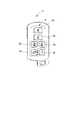
図2に、携帯機1における操作部2のスイッチ構成の一例を示す。操作部2は、車両10の全ドア(11〜15、図1参照)のロックを行うためのロックスイッチ2a、全ドアのアンロックを行うためのアンロックスイッチ2b、右スライドドア13の開閉動作を行うための右PSD(Power Sliding Door)スイッチ2c、左スライドドア14の開閉動作を行うための左PSDスイッチ2d、バックドア15の開閉動作を行うためのPBD(Power Back Door)スイッチ2e、左右のスライドドア(13、14)あるいはバックドア15の開閉動作の予約を行うための予約スイッチ2fを含んでいる。なお、右PSDスイッチ2c、左PSDスイッチ2d、PBDスイッチ2e、予約スイッチ2fが本発明の駆動予約設定部に相当する。また、上述の開閉動作の予約とは関係ない操作により送信機1bから送信する制御信号を、通常の制御信号という。 FIG. 2 shows an example of a switch configuration of the
図1に戻り、車両10には、前席に対応して、ヒンジ式のドア11、12が設けられており、後席に対応して、スライド式の右スライドドア13、左スライドドア14が設けられている。これらスライドドア13、14には、それぞれ、モータを駆動源とする右スライドドア駆動部9c、左スライドドア駆動部9dが設けられており、キーレスECU4からの開扉/閉扉信号に従って、モータを駆動して各スライドドア13、14を開扉/閉扉することが可能である。 Returning to FIG. 1, the
また、車両10は、後部にバックドア15を備える。このバックドア15にも、モータを駆動源とするバックドア駆動部9eが設けられており、キーレスECU4からの開扉/閉扉信号に従って、モータを駆動してバックドア15を開扉/閉扉することができる。 The
なお、上述のスライドドア駆動部9c、9d、バックドア駆動部9eは、車載装置に含まれ、本発明のドア駆動部に相当する。 In addition, the above-mentioned slide
また、車載装置は、車両10の各ドア11〜15に設けられ、その各ドア11〜15をロック・アンロック状態に制御するドアロック制御部5a〜5eを有する。このドアロック制御部5a〜5eは、キーレスECU4からの制御信号に応じて動作する。 The in-vehicle device includes door
また、車載装置は、車両10の車室内に設けられ、携帯機1から送信される制御信号を受信する受信機3を有する。受信機3が受信した制御信号は、キーレスECU4に出力される。キーレスECU4は、例えば周知のマイクロコンピュータとして構成され、この受信した制御信号の内容に基づいて、各ドア(11〜15)のロック・アンロック状態の制御を実行すべきか否か、各スライドドア(13、14)あるいはバックドア15の開扉/閉扉制御を実行すべきか否か等の判定を行う。例えば、該当するドア(スライドドアあるいはバックドア)が、閉状態のときはアンロック状態とした後に開状態に遷移させ、開状態のときには閉状態に遷移させた後にロック状態とする。これら、スライドドア装置については、例えば特許文献3に詳細が記載されている。 Further, the in-vehicle device includes a
なお、受信機3、キーレスECU4は、車載装置に含まれる。また、受信機3が本発明の受信部に相当し、キーレスECU4が本発明の駆動制御部に相当する。 The
図3を用いて、携帯機ECU1aにおいて実行される駆動予約処理について説明する。なお、本処理は、携帯機ECU1aのROMに記憶されてCPUが実行する携帯機制御プログラムに含まれ、携帯機制御プログラムの他の処理とともに繰り返し実行される。まず、ユーザによる予約スイッチ(SW)2fの操作を検出する(S11)。予約スイッチ2fの操作が予め定められた回数行われたことを検出したとき(S12:Yes)、駆動予約対象となるドアが選択された否かを検出する(S13)。すなわち、右PSDスイッチ2c、左PSDスイッチ2d、PBDスイッチ2eのいずれが操作されたかを検出する。 A drive reservation process executed in the
なお、予約スイッチ2fの操作を検出した後、予め定められた時間内に、次のスイッチ操作(予約スイッチ2f、右PSDスイッチ2c、左PSDスイッチ2d、PBDスイッチ2eのいずれか)を検出しないときには、それまでの操作を無効としてもよい。 When the operation of the
駆動予約対象となるドアが選択されたとき、予約スイッチ2fの操作に基づいて設定されたディレイ時間nTdが経過するのを待つ(S14)。ディレイ時間nTdは、該当するドアを開状態とするための制御信号(以下、「駆動予約信号」ともいう)の送信を開始するまでの時間で、例えば、ユーザが現在いる位置から車両10の受信機3の受信範囲の外縁に到達すると思われる時間に相当するものである。なお、車両10の受信機3の受信範囲は、受信機3の仕様によって決まる。ディレイ時間nTdの設定は、以下のうちのいずれを用いてもよい。 When the door to be reserved for driving is selected, it waits for the delay time nTd set based on the operation of the
・Tdを例えば10秒のような単位時間とし、予約スイッチ2fの操作回数nとの積をディレイ時間nTdとする。
・予約スイッチ2fの操作回数とディレイ時間nTdとの関係をマップデータとして予めROM(図示せず)に記憶しておき、マップデータから、予約スイッチ2fの操作回数に対応したディレイ時間nTdを設定する。例えば、予約スイッチ2fの操作回数が多いほど、ユーザが車両10の近くにいると判定して、予約スイッチ2fの操作回数に応じて、「近距離用」、「中距離用」、「遠距離用」というような3段階のディレイ時間nTdを設定する。Td is a unit time such as 10 seconds, for example, and the product of the number n of operations of the
A relationship between the number of operations of the
ディレイ時間nTdが経過した後、タイマーtに送信時間nTrをセットし、カウント動作を開始する(S15)。送信時間nTrは、ユーザが車両の受信部の受信範囲の外縁から車両への到達時間に相当するものである。車両10から例えば1〜2mの距離(すなわち、受信機3が駆動予約信号を確実に受信できる範囲)に近づいたときに、駆動予約信号の送信を停止することが望ましい。また、送信時間nTrは、以下のうちのいずれを用いてもよい。
・Trを例えば10秒のような単位時間とし、予約スイッチ2fの操作回数nとの積を送信時間nTrとする。
・予約スイッチ2fの操作回数と送信時間nTrとの関係をマップデータとして予めROM(図示せず)に記憶しておき、マップデータから、予約スイッチ2fの操作回数に対応した送信時間nTrを設定する。
・ディレイ時間nTdと送信時間nTrとの関係をマップデータとして予めROM(図示せず)に記憶しておき、マップデータから、ディレイ時間nTdに対応した送信時間nTrを設定する。例えば、ユーザが車両10のより近くにいるときには、送信時間nTrは短くなる。
・予め定められた一定値(例えば、30秒)とする。After the delay time nTd has elapsed, the transmission time nTr is set in the timer t, and the count operation is started (S15). The transmission time nTr corresponds to the arrival time from the outer edge of the reception range of the receiving unit of the vehicle to the vehicle. For example, when the
Tr is a unit time such as 10 seconds, for example, and the product of the number n of operations of the
A relationship between the number of operations of the
The relationship between the delay time nTd and the transmission time nTr is stored in advance in a ROM (not shown) as map data, and the transmission time nTr corresponding to the delay time nTd is set from the map data. For example, when the user is closer to the
-It is set to a predetermined constant value (for example, 30 seconds).
そして、タイマーtがゼロとなったとき(S16:No)、駆動予約信号の送信を停止し(S21)、本処理を終了する。一方、タイマーtがゼロでないとき(S16:Yes)、以下のいずれかの方法により駆動予約信号を送信する(S17)。
・通常の制御信号と同様の電界強度(詳細は後述)で間歇送信する。
・電界強度を通常の制御信号よりも小さくして間歇送信する。
・電界強度を送信時間nTrの始めのうちは通常の制御信号よりも小さくし、タイマーtがゼロに近づくにつれて通常の制御信号と同じとなるように漸増してに間歇送信する。
・電界強度を通常の制御信号よりも小さくして連続送信する。When the timer t becomes zero (S16: No), the transmission of the drive reservation signal is stopped (S21), and this process is terminated. On the other hand, when the timer t is not zero (S16: Yes), a drive reservation signal is transmitted by one of the following methods (S17).
-Transmit intermittently with the same electric field strength as the normal control signal (details will be described later).
-Transmit intermittently with the electric field strength lower than the normal control signal.
The electric field strength is set to be smaller than the normal control signal at the beginning of the transmission time nTr, and intermittent transmission is performed while gradually increasing to become the same as the normal control signal as the timer t approaches zero.
・ Continuous transmission with electric field strength smaller than normal control signal.
駆動予約信号の送信時間内に、携帯機1のいずれかのスイッチ(2a〜2f)の操作を検出したとき(S18:Yes)、駆動予約信号の送信を中止して(S21)、本処理を終了する。一方、駆動予約信号の送信中に、携帯機1のいずれのスイッチ(2a〜2f)の操作も検出しない間は(S18:No)、駆動予約信号の送信を継続するとともに(S19)、タイマーtのカウントダウンを継続し(S20)、ステップS16へ戻る。 When the operation of any of the switches (2a to 2f) of the
車両10では、受信機3が駆動予約信号を受信すると、その情報がキーレスECU4に送られ、該当するドアロック制御部(5c〜5eのいずれか)に指令を送り、ドアを開錠した後、開状態とするようにスライドドア駆動部(9c、9d)あるいはバックドア駆動部(9e)の駆動制御を行う。 In the
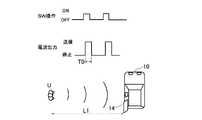
図4および図5を用いて、本発明における駆動予約信号の送信の詳細について説明する。図4は、携帯機1のいずれかのスイッチ(2a〜2e)の操作を検出したときに送信される、通常の制御信号の送信状態を表したものである。図4のように、スイッチ操作が検出される毎に、操作されたスイッチの種別に応じて、例えば450msecのような所定時間T0だけ電波が送信される。このときの電界強度は、例えば70dBμV/mとなるように電波の送信出力が調整されている。 Details of transmission of the drive reservation signal in the present invention will be described with reference to FIGS. FIG. 4 shows a transmission state of a normal control signal transmitted when an operation of any one of the switches (2a to 2e) of the
つまり、図4の例では、ユーザUは、車両10から比較的遠い距離L1離れた場所からでも、左スライドドア14の開扉を行うことができるが、悪意を持った者に侵入される危険性がある、あるいは、雨天時には雨が降り込む、といった問題が生ずる。 In other words, in the example of FIG. 4, the user U can open the
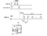
図5は、本発明の構成における駆動予約信号の送信状態を表したものである。図5の例では、ユーザUが予約スイッチ(SW)2fを操作し、それに引き続いて左右のPSDスイッチ(2cあるいは2d)、あるいはPBDスイッチ2eを操作すると、上述のように、予約スイッチを操作した回数nに基づいてディレイ時間(図5の例では、n×Td,Tdは単位時間)が設定され、PSDスイッチ(2cあるいは2d)あるいはPBDスイッチ2eが操作されてからディレイ時間(n×Td)が経過した後に、上述のようにして設定された送信時間(図5の例では、n×Tr)だけ駆動予約信号が送信される。 FIG. 5 shows a transmission state of the drive reservation signal in the configuration of the present invention. In the example of FIG. 5, when the user U operates the reservation switch (SW) 2f and subsequently operates the left and right PSD switches (2c or 2d) or the
図5の例では、駆動予約信号の電界強度は、図4の通常の制御信号よりも小さい、例えば50dBμV/mとなるように電波の送信出力が調整されている。また、送信周期T2は例えば1秒、送信時間T1は例えば450msecとなっている。駆動予約信号の電界強度を小さくすることで、車両10の受信機3の受信範囲が通常よりも狭くなり、ユーザUが、図4の例よりも、より車両10に近づいた距離L2の位置で左スライドドア14が開扉し、開扉してからユーザUが車両10に乗り込むまでの時間を短縮することができ、不審者の侵入や雨の降り込みを防止することができる。 In the example of FIG. 5, the radio wave transmission output is adjusted so that the electric field intensity of the drive reservation signal is smaller than the normal control signal of FIG. 4, for example, 50 dBμV / m. The transmission cycle T2 is 1 second, for example, and the transmission time T1 is 450 msec, for example. By reducing the electric field strength of the drive reservation signal, the reception range of the
上述の例は、ユーザが車両10に乗車するときについて述べたものであるが、荷物を持って車両10から降車するときにも適用できる。すなわち、まず、ドア(スライドドア13、14、あるいはバックドア15)を開け、予約スイッチ2fを操作し、閉めたいドアを選択してから、荷物を持って降車する。その後ディレイ時間が経過したときに、駆動予約信号が送信されて開状態のドアが閉状態となる(その後、施錠される)。これにより、両手が荷物等で塞がっていても降車後にスイッチを操作することなく車両を施錠することができる。 The above example describes the case where the user gets on the
以上、本発明の実施の形態を説明したが、これらはあくまで例示にすぎず、本発明はこれらに限定されるものではなく、特許請求の範囲の趣旨を逸脱しない限りにおいて、当業者の知識に基づく種々の変更が可能である。 Although the embodiments of the present invention have been described above, these are merely examples, and the present invention is not limited to these embodiments, and the knowledge of those skilled in the art can be used without departing from the spirit of the claims. Various modifications based on this are possible.
1 携帯機
1a 携帯機ECU(送信制御部,ディレイ時間生成部)
1b 送信機(送信部)
2 操作部
2c 右PSDスイッチ(駆動予約設定部)
2d 左PSDスイッチ(駆動予約設定部)
2e PBDスイッチ(駆動予約設定部)
2f 予約スイッチ(駆動予約設定部)
3 受信機(車載装置,受信部)
4 キーレスECU(車載装置,駆動制御部)
9c 右スライドドア駆動部(車載装置,ドア駆動部)
9d 左スライドドア駆動部(車載装置,ドア駆動部)
9e バックドア駆動部(車載装置,ドア駆動部)
10 車両
13 右スライドドア(スライドドア)
14 左スライドドア(スライドドア)
15 バックドア
100 車両用キーレスエントリーシステム1
1b Transmitter (transmitter)
2
2d Left PSD switch (drive reservation setting part)
2e PBD switch (drive reservation setting part)
2f reservation switch (drive reservation setting part)
3 receivers (vehicle equipment, receiver)
4 Keyless ECU (on-vehicle device, drive control unit)
9c Right slide door drive unit (on-vehicle device, door drive unit)
9d Left slide door drive (on-vehicle device, door drive)
9e Back door drive part (vehicle equipment, door drive part)
10
14 Left sliding door (sliding door)
15
Claims (6)
Translated fromJapanese前記車両に搭載され、前記制御信号を受信する受信部と、受信した前記制御信号に基づいて、前記車両のドアを閉状態あるいは開状態に遷移させるための駆動を行うドア駆動部の駆動制御を行う駆動制御部とを有する車載装置と、
を備えた車両用キーレスエントリーシステムであって、
前記携帯機は、
前記ユーザの操作により、前記車両のドアを閉状態あるいは開状態に遷移させるための駆動予約の設定を行う駆動予約設定部と、
設定した前記駆動予約に基づいて、前記駆動予約を設定した時点を基準とする、予め定められたディレイ時間を生成するディレイ時間生成部と、
をさらに有し、
前記送信制御部は、前記駆動予約の設定を行ってから前記ディレイ時間が経過した後に、予め定められた送信時間だけ、前記車両のドアを閉状態あるいは開状態に遷移させるための制御信号を前記送信部から送信するよう制御することを特徴とする車両用キーレスエントリーシステム。A user-owned operation unit, and a transmission control unit configured to control the transmission unit to transmit a control signal for transitioning the vehicle door to a closed state or an open state based on an operation of the operation unit by the user; A portable machine having,
Drive control mounted on the vehicle for receiving the control signal and for driving the door drive unit for driving the vehicle door to a closed state or an open state based on the received control signal. An in-vehicle device having a drive control unit to perform;
A keyless entry system for vehicles equipped with
The portable device is
A drive reservation setting unit configured to set a drive reservation for shifting the door of the vehicle to a closed state or an open state by an operation of the user;
A delay time generation unit that generates a predetermined delay time based on the time when the drive reservation is set based on the set drive reservation;
Further comprising
The transmission control unit outputs a control signal for transitioning the door of the vehicle to a closed state or an open state for a predetermined transmission time after the delay time has elapsed since the setting of the drive reservation. A vehicle keyless entry system that is controlled to transmit from a transmitter.
Priority Applications (1)
| Application Number | Priority Date | Filing Date | Title |
|---|---|---|---|
| JP2010253546AJP5423988B2 (en) | 2010-11-12 | 2010-11-12 | Keyless entry system for vehicles |
Applications Claiming Priority (1)
| Application Number | Priority Date | Filing Date | Title |
|---|---|---|---|
| JP2010253546AJP5423988B2 (en) | 2010-11-12 | 2010-11-12 | Keyless entry system for vehicles |
Publications (2)
| Publication Number | Publication Date |
|---|---|
| JP2012102585A JP2012102585A (en) | 2012-05-31 |
| JP5423988B2true JP5423988B2 (en) | 2014-02-19 |
Family
ID=46393282
Family Applications (1)
| Application Number | Title | Priority Date | Filing Date |
|---|---|---|---|
| JP2010253546AExpired - Fee RelatedJP5423988B2 (en) | 2010-11-12 | 2010-11-12 | Keyless entry system for vehicles |
Country Status (1)
| Country | Link |
|---|---|
| JP (1) | JP5423988B2 (en) |
Cited By (1)
| Publication number | Priority date | Publication date | Assignee | Title |
|---|---|---|---|---|
| JP2016113860A (en)* | 2014-12-18 | 2016-06-23 | アイシン精機株式会社 | Control device of opening/closing body for vehicle and control system |
Families Citing this family (12)
| Publication number | Priority date | Publication date | Assignee | Title |
|---|---|---|---|---|
| JP5846024B2 (en) | 2012-04-11 | 2016-01-20 | 株式会社デンソー | Keyless entry system |
| WO2014125650A1 (en)* | 2013-02-18 | 2014-08-21 | トヨタ自動車株式会社 | Vehicle control device |
| JP2015071888A (en)* | 2013-10-03 | 2015-04-16 | 株式会社デンソー | Vehicle control system |
| JP6172086B2 (en) | 2014-08-08 | 2017-08-02 | トヨタ自動車株式会社 | Vehicle control device |
| CN108368708B (en)* | 2015-06-04 | 2020-03-13 | 株式会社自动网络技术研究所 | Vehicle communication system and in-vehicle device |
| US9816308B2 (en)* | 2016-02-17 | 2017-11-14 | Ford Global Technologies, Llc | Methods and systems for opening of a vehicle access point using audio or video data associated with a user |
| JP2018127830A (en)* | 2017-02-09 | 2018-08-16 | オムロンオートモーティブエレクトロニクス株式会社 | Vehicle control system and vehicle control device |
| JP2018178669A (en)* | 2017-04-21 | 2018-11-15 | 株式会社ユーシン | Vehicle opening / closing body drive control device |
| JP6825472B2 (en)* | 2017-04-24 | 2021-02-03 | アイシン精機株式会社 | Opening and closing body control device for vehicles |
| JP6807137B2 (en)* | 2017-05-31 | 2021-01-06 | ダイハツ工業株式会社 | Vehicle door reservation open system |
| CN114347948B (en)* | 2022-01-19 | 2023-03-21 | 浙江吉利控股集团有限公司 | Vehicle control method, device, equipment and medium |
| CN117605359A (en)* | 2023-11-17 | 2024-02-27 | 长城汽车股份有限公司 | Vehicle door control method, device, vehicle and computer readable storage medium |
Family Cites Families (3)
| Publication number | Priority date | Publication date | Assignee | Title |
|---|---|---|---|---|
| JP3179839B2 (en)* | 1992-02-19 | 2001-06-25 | ナルデック株式会社 | Remote control device for in-vehicle electrical components |
| JP2001355363A (en)* | 2000-06-13 | 2001-12-26 | Yuhshin Co Ltd | Motor vehicle keyless entry device |
| JP2005226444A (en)* | 2004-01-14 | 2005-08-25 | Mitsuba Corp | Automatic opening-closing device for vehicle |
- 2010
- 2010-11-12JPJP2010253546Apatent/JP5423988B2/ennot_activeExpired - Fee Related
Cited By (2)
| Publication number | Priority date | Publication date | Assignee | Title |
|---|---|---|---|---|
| JP2016113860A (en)* | 2014-12-18 | 2016-06-23 | アイシン精機株式会社 | Control device of opening/closing body for vehicle and control system |
| US10013827B2 (en) | 2014-12-18 | 2018-07-03 | Aisin Seiki Kabushiki Kaisha | Control device and control system for vehicle opening/closing body |
Also Published As
| Publication number | Publication date |
|---|---|
| JP2012102585A (en) | 2012-05-31 |
Similar Documents
| Publication | Publication Date | Title |
|---|---|---|
| JP5423988B2 (en) | Keyless entry system for vehicles | |
| KR100638388B1 (en) | Keyless entry device | |
| JP4535031B2 (en) | In-vehicle device remote control system | |
| JP4529762B2 (en) | Vehicle door control system | |
| US9478848B2 (en) | In-vehicle system | |
| JP5381515B2 (en) | Automatic locking device | |
| JP5482700B2 (en) | Vehicle door opening / closing control device | |
| KR102578199B1 (en) | Remote controller and vehicle communication with the remote controller and method for controlling the vehicle | |
| US9008861B2 (en) | Vehicle device control system with a disabling feature | |
| JP4022859B2 (en) | Door lock control device | |
| JP6380004B2 (en) | In-vehicle machine | |
| WO2018003345A1 (en) | Occupant detection system and occupant detection device | |
| JP4953709B2 (en) | Keyless device for vehicle | |
| JPH112053A (en) | Passive entry control system for vehicle | |
| JP6323298B2 (en) | Electronic key system and portable device | |
| JP6016089B2 (en) | Smart system | |
| WO2014125650A1 (en) | Vehicle control device | |
| JP2017082407A (en) | Vehicle door control system | |
| JP5451128B2 (en) | Keyless entry device for vehicles | |
| KR102303232B1 (en) | System and method for controlling tail gate of vehicles | |
| JP2004084254A (en) | Keyless entry system | |
| JP2015113613A (en) | Locking-unlocking control device and system | |
| JP2004068434A (en) | Keyless entry system | |
| JP4431876B2 (en) | Keyless entry device for vehicles | |
| JP2000352243A (en) | Vehicular smart keyless entry system |
Legal Events
| Date | Code | Title | Description |
|---|---|---|---|
| RD02 | Notification of acceptance of power of attorney | Free format text:JAPANESE INTERMEDIATE CODE: A7422 Effective date:20121013 | |
| A621 | Written request for application examination | Free format text:JAPANESE INTERMEDIATE CODE: A621 Effective date:20130308 | |
| A977 | Report on retrieval | Free format text:JAPANESE INTERMEDIATE CODE: A971007 Effective date:20131008 | |
| TRDD | Decision of grant or rejection written | ||
| A01 | Written decision to grant a patent or to grant a registration (utility model) | Free format text:JAPANESE INTERMEDIATE CODE: A01 Effective date:20131030 | |
| A61 | First payment of annual fees (during grant procedure) | Free format text:JAPANESE INTERMEDIATE CODE: A61 Effective date:20131112 | |
| R151 | Written notification of patent or utility model registration | Ref document number:5423988 Country of ref document:JP Free format text:JAPANESE INTERMEDIATE CODE: R151 | |
| R250 | Receipt of annual fees | Free format text:JAPANESE INTERMEDIATE CODE: R250 | |
| R250 | Receipt of annual fees | Free format text:JAPANESE INTERMEDIATE CODE: R250 | |
| R250 | Receipt of annual fees | Free format text:JAPANESE INTERMEDIATE CODE: R250 | |
| LAPS | Cancellation because of no payment of annual fees |