JP5423829B2 - Exposure apparatus, device manufacturing method, and exposure apparatus control method - Google Patents
Exposure apparatus, device manufacturing method, and exposure apparatus control methodDownload PDFInfo
- Publication number
- JP5423829B2 JP5423829B2JP2012066139AJP2012066139AJP5423829B2JP 5423829 B2JP5423829 B2JP 5423829B2JP 2012066139 AJP2012066139 AJP 2012066139AJP 2012066139 AJP2012066139 AJP 2012066139AJP 5423829 B2JP5423829 B2JP 5423829B2
- Authority
- JP
- Japan
- Prior art keywords
- liquid
- substrate
- exposure apparatus
- immersion exposure
- recovery
- Prior art date
- Legal status (The legal status is an assumption and is not a legal conclusion. Google has not performed a legal analysis and makes no representation as to the accuracy of the status listed.)
- Expired - Fee Related
Links
Images


Classifications
- G—PHYSICS
- G03—PHOTOGRAPHY; CINEMATOGRAPHY; ANALOGOUS TECHNIQUES USING WAVES OTHER THAN OPTICAL WAVES; ELECTROGRAPHY; HOLOGRAPHY
- G03F—PHOTOMECHANICAL PRODUCTION OF TEXTURED OR PATTERNED SURFACES, e.g. FOR PRINTING, FOR PROCESSING OF SEMICONDUCTOR DEVICES; MATERIALS THEREFOR; ORIGINALS THEREFOR; APPARATUS SPECIALLY ADAPTED THEREFOR
- G03F7/00—Photomechanical, e.g. photolithographic, production of textured or patterned surfaces, e.g. printing surfaces; Materials therefor, e.g. comprising photoresists; Apparatus specially adapted therefor
- G03F7/70—Microphotolithographic exposure; Apparatus therefor
- G03F7/708—Construction of apparatus, e.g. environment aspects, hygiene aspects or materials
- G03F7/70858—Environment aspects, e.g. pressure of beam-path gas, temperature
- G03F7/70866—Environment aspects, e.g. pressure of beam-path gas, temperature of mask or workpiece
- G—PHYSICS
- G03—PHOTOGRAPHY; CINEMATOGRAPHY; ANALOGOUS TECHNIQUES USING WAVES OTHER THAN OPTICAL WAVES; ELECTROGRAPHY; HOLOGRAPHY
- G03F—PHOTOMECHANICAL PRODUCTION OF TEXTURED OR PATTERNED SURFACES, e.g. FOR PRINTING, FOR PROCESSING OF SEMICONDUCTOR DEVICES; MATERIALS THEREFOR; ORIGINALS THEREFOR; APPARATUS SPECIALLY ADAPTED THEREFOR
- G03F7/00—Photomechanical, e.g. photolithographic, production of textured or patterned surfaces, e.g. printing surfaces; Materials therefor, e.g. comprising photoresists; Apparatus specially adapted therefor
- G03F7/70—Microphotolithographic exposure; Apparatus therefor
- G03F7/70216—Mask projection systems
- G03F7/70341—Details of immersion lithography aspects, e.g. exposure media or control of immersion liquid supply
- G—PHYSICS
- G03—PHOTOGRAPHY; CINEMATOGRAPHY; ANALOGOUS TECHNIQUES USING WAVES OTHER THAN OPTICAL WAVES; ELECTROGRAPHY; HOLOGRAPHY
- G03F—PHOTOMECHANICAL PRODUCTION OF TEXTURED OR PATTERNED SURFACES, e.g. FOR PRINTING, FOR PROCESSING OF SEMICONDUCTOR DEVICES; MATERIALS THEREFOR; ORIGINALS THEREFOR; APPARATUS SPECIALLY ADAPTED THEREFOR
- G03F7/00—Photomechanical, e.g. photolithographic, production of textured or patterned surfaces, e.g. printing surfaces; Materials therefor, e.g. comprising photoresists; Apparatus specially adapted therefor
- G03F7/70—Microphotolithographic exposure; Apparatus therefor
- G03F7/70483—Information management; Active and passive control; Testing; Wafer monitoring, e.g. pattern monitoring
- G03F7/70491—Information management, e.g. software; Active and passive control, e.g. details of controlling exposure processes or exposure tool monitoring processes
- G03F7/70525—Controlling normal operating mode, e.g. matching different apparatus, remote control or prediction of failure
- G—PHYSICS
- G03—PHOTOGRAPHY; CINEMATOGRAPHY; ANALOGOUS TECHNIQUES USING WAVES OTHER THAN OPTICAL WAVES; ELECTROGRAPHY; HOLOGRAPHY
- G03F—PHOTOMECHANICAL PRODUCTION OF TEXTURED OR PATTERNED SURFACES, e.g. FOR PRINTING, FOR PROCESSING OF SEMICONDUCTOR DEVICES; MATERIALS THEREFOR; ORIGINALS THEREFOR; APPARATUS SPECIALLY ADAPTED THEREFOR
- G03F7/00—Photomechanical, e.g. photolithographic, production of textured or patterned surfaces, e.g. printing surfaces; Materials therefor, e.g. comprising photoresists; Apparatus specially adapted therefor
- G03F7/70—Microphotolithographic exposure; Apparatus therefor
- G03F7/70483—Information management; Active and passive control; Testing; Wafer monitoring, e.g. pattern monitoring
- G03F7/70491—Information management, e.g. software; Active and passive control, e.g. details of controlling exposure processes or exposure tool monitoring processes
- G03F7/70533—Controlling abnormal operating mode, e.g. taking account of waiting time, decision to rework or rework flow
- G—PHYSICS
- G03—PHOTOGRAPHY; CINEMATOGRAPHY; ANALOGOUS TECHNIQUES USING WAVES OTHER THAN OPTICAL WAVES; ELECTROGRAPHY; HOLOGRAPHY
- G03F—PHOTOMECHANICAL PRODUCTION OF TEXTURED OR PATTERNED SURFACES, e.g. FOR PRINTING, FOR PROCESSING OF SEMICONDUCTOR DEVICES; MATERIALS THEREFOR; ORIGINALS THEREFOR; APPARATUS SPECIALLY ADAPTED THEREFOR
- G03F7/00—Photomechanical, e.g. photolithographic, production of textured or patterned surfaces, e.g. printing surfaces; Materials therefor, e.g. comprising photoresists; Apparatus specially adapted therefor
- G03F7/70—Microphotolithographic exposure; Apparatus therefor
- G03F7/70691—Handling of masks or workpieces
- G03F7/70716—Stages
- G03F7/70725—Stages control
- G—PHYSICS
- G03—PHOTOGRAPHY; CINEMATOGRAPHY; ANALOGOUS TECHNIQUES USING WAVES OTHER THAN OPTICAL WAVES; ELECTROGRAPHY; HOLOGRAPHY
- G03F—PHOTOMECHANICAL PRODUCTION OF TEXTURED OR PATTERNED SURFACES, e.g. FOR PRINTING, FOR PROCESSING OF SEMICONDUCTOR DEVICES; MATERIALS THEREFOR; ORIGINALS THEREFOR; APPARATUS SPECIALLY ADAPTED THEREFOR
- G03F7/00—Photomechanical, e.g. photolithographic, production of textured or patterned surfaces, e.g. printing surfaces; Materials therefor, e.g. comprising photoresists; Apparatus specially adapted therefor
- G03F7/70—Microphotolithographic exposure; Apparatus therefor
- G03F7/70691—Handling of masks or workpieces
- G03F7/70758—Drive means, e.g. actuators, motors for long- or short-stroke modules or fine or coarse driving
- G—PHYSICS
- G03—PHOTOGRAPHY; CINEMATOGRAPHY; ANALOGOUS TECHNIQUES USING WAVES OTHER THAN OPTICAL WAVES; ELECTROGRAPHY; HOLOGRAPHY
- G03F—PHOTOMECHANICAL PRODUCTION OF TEXTURED OR PATTERNED SURFACES, e.g. FOR PRINTING, FOR PROCESSING OF SEMICONDUCTOR DEVICES; MATERIALS THEREFOR; ORIGINALS THEREFOR; APPARATUS SPECIALLY ADAPTED THEREFOR
- G03F7/00—Photomechanical, e.g. photolithographic, production of textured or patterned surfaces, e.g. printing surfaces; Materials therefor, e.g. comprising photoresists; Apparatus specially adapted therefor
- G03F7/70—Microphotolithographic exposure; Apparatus therefor
- G03F7/708—Construction of apparatus, e.g. environment aspects, hygiene aspects or materials
- G03F7/70808—Construction details, e.g. housing, load-lock, seals or windows for passing light in or out of apparatus
- G03F7/70841—Constructional issues related to vacuum environment, e.g. load-lock chamber
- G—PHYSICS
- G03—PHOTOGRAPHY; CINEMATOGRAPHY; ANALOGOUS TECHNIQUES USING WAVES OTHER THAN OPTICAL WAVES; ELECTROGRAPHY; HOLOGRAPHY
- G03F—PHOTOMECHANICAL PRODUCTION OF TEXTURED OR PATTERNED SURFACES, e.g. FOR PRINTING, FOR PROCESSING OF SEMICONDUCTOR DEVICES; MATERIALS THEREFOR; ORIGINALS THEREFOR; APPARATUS SPECIALLY ADAPTED THEREFOR
- G03F7/00—Photomechanical, e.g. photolithographic, production of textured or patterned surfaces, e.g. printing surfaces; Materials therefor, e.g. comprising photoresists; Apparatus specially adapted therefor
- G03F7/70—Microphotolithographic exposure; Apparatus therefor
- G03F7/708—Construction of apparatus, e.g. environment aspects, hygiene aspects or materials
- G03F7/7085—Detection arrangement, e.g. detectors of apparatus alignment possibly mounted on wafers, exposure dose, photo-cleaning flux, stray light, thermal load
- G—PHYSICS
- G03—PHOTOGRAPHY; CINEMATOGRAPHY; ANALOGOUS TECHNIQUES USING WAVES OTHER THAN OPTICAL WAVES; ELECTROGRAPHY; HOLOGRAPHY
- G03F—PHOTOMECHANICAL PRODUCTION OF TEXTURED OR PATTERNED SURFACES, e.g. FOR PRINTING, FOR PROCESSING OF SEMICONDUCTOR DEVICES; MATERIALS THEREFOR; ORIGINALS THEREFOR; APPARATUS SPECIALLY ADAPTED THEREFOR
- G03F7/00—Photomechanical, e.g. photolithographic, production of textured or patterned surfaces, e.g. printing surfaces; Materials therefor, e.g. comprising photoresists; Apparatus specially adapted therefor
- G03F7/70—Microphotolithographic exposure; Apparatus therefor
- G03F7/708—Construction of apparatus, e.g. environment aspects, hygiene aspects or materials
- G03F7/70858—Environment aspects, e.g. pressure of beam-path gas, temperature
- G03F7/709—Vibration, e.g. vibration detection, compensation, suppression or isolation
- H—ELECTRICITY
- H01—ELECTRIC ELEMENTS
- H01L—SEMICONDUCTOR DEVICES NOT COVERED BY CLASS H10
- H01L21/00—Processes or apparatus adapted for the manufacture or treatment of semiconductor or solid state devices or of parts thereof
- H01L21/02—Manufacture or treatment of semiconductor devices or of parts thereof
- H01L21/027—Making masks on semiconductor bodies for further photolithographic processing not provided for in group H01L21/18 or H01L21/34
- H01L21/0271—Making masks on semiconductor bodies for further photolithographic processing not provided for in group H01L21/18 or H01L21/34 comprising organic layers
- H01L21/0273—Making masks on semiconductor bodies for further photolithographic processing not provided for in group H01L21/18 or H01L21/34 comprising organic layers characterised by the treatment of photoresist layers
- H01L21/0274—Photolithographic processes
- H—ELECTRICITY
- H01—ELECTRIC ELEMENTS
- H01L—SEMICONDUCTOR DEVICES NOT COVERED BY CLASS H10
- H01L21/00—Processes or apparatus adapted for the manufacture or treatment of semiconductor or solid state devices or of parts thereof
- H01L21/67—Apparatus specially adapted for handling semiconductor or electric solid state devices during manufacture or treatment thereof; Apparatus specially adapted for handling wafers during manufacture or treatment of semiconductor or electric solid state devices or components ; Apparatus not specifically provided for elsewhere
- H01L21/67005—Apparatus not specifically provided for elsewhere
- H01L21/67242—Apparatus for monitoring, sorting or marking
- H01L21/67259—Position monitoring, e.g. misposition detection or presence detection
- H—ELECTRICITY
- H01—ELECTRIC ELEMENTS
- H01L—SEMICONDUCTOR DEVICES NOT COVERED BY CLASS H10
- H01L21/00—Processes or apparatus adapted for the manufacture or treatment of semiconductor or solid state devices or of parts thereof
- H01L21/67—Apparatus specially adapted for handling semiconductor or electric solid state devices during manufacture or treatment thereof; Apparatus specially adapted for handling wafers during manufacture or treatment of semiconductor or electric solid state devices or components ; Apparatus not specifically provided for elsewhere
- H01L21/67005—Apparatus not specifically provided for elsewhere
- H01L21/67242—Apparatus for monitoring, sorting or marking
- H01L21/67288—Monitoring of warpage, curvature, damage, defects or the like
- H—ELECTRICITY
- H01—ELECTRIC ELEMENTS
- H01L—SEMICONDUCTOR DEVICES NOT COVERED BY CLASS H10
- H01L21/00—Processes or apparatus adapted for the manufacture or treatment of semiconductor or solid state devices or of parts thereof
- H01L21/67—Apparatus specially adapted for handling semiconductor or electric solid state devices during manufacture or treatment thereof; Apparatus specially adapted for handling wafers during manufacture or treatment of semiconductor or electric solid state devices or components ; Apparatus not specifically provided for elsewhere
- H01L21/68—Apparatus specially adapted for handling semiconductor or electric solid state devices during manufacture or treatment thereof; Apparatus specially adapted for handling wafers during manufacture or treatment of semiconductor or electric solid state devices or components ; Apparatus not specifically provided for elsewhere for positioning, orientation or alignment
Landscapes
- Physics & Mathematics (AREA)
- General Physics & Mathematics (AREA)
- Engineering & Computer Science (AREA)
- Health & Medical Sciences (AREA)
- Environmental & Geological Engineering (AREA)
- Epidemiology (AREA)
- Public Health (AREA)
- Life Sciences & Earth Sciences (AREA)
- Atmospheric Sciences (AREA)
- Toxicology (AREA)
- Manufacturing & Machinery (AREA)
- Computer Hardware Design (AREA)
- Microelectronics & Electronic Packaging (AREA)
- Power Engineering (AREA)
- Condensed Matter Physics & Semiconductors (AREA)
- Exposure And Positioning Against Photoresist Photosensitive Materials (AREA)
- Exposure Of Semiconductors, Excluding Electron Or Ion Beam Exposure (AREA)
- Optics & Photonics (AREA)
- Container, Conveyance, Adherence, Positioning, Of Wafer (AREA)
Description
Translated fromJapanese本発明は、投影光学系と液体とを介して基板を露光する露光装置、この露光装置を用いるデバイス製造方法、及び露光装置の制御方法に関するものである。 The present invention relates to an exposure apparatus that exposes a substrate through a projection optical system and a liquid, a device manufacturing method using the exposure apparatus, and a control method for the exposure apparatus.
半導体デバイスや液晶表示デバイスは、マスク上に形成されたパターンを感光性の基板上に転写する、所謂フォトリソグラフィの手法により製造される。このフォトリソグラフィ工程で使用される露光装置は、マスクを支持するマスクステージと基板を支持する基板ステージとを有し、マスクステージ及び基板ステージを逐次移動しながらマスクのパターンを投影光学系を介して基板に転写するものである。近年、デバイスパターンのより一層の高集積化に対応するために投影光学系の更なる高解像度化が望まれている。投影光学系の解像度は、使用する露光波長が短いほど、また投影光学系の開口数が大きいほど高くなる。そのため、露光装置で使用される露光波長は年々短波長化しており、投影光学系の開口数も増大している。そして、現在主流の露光波長はKrFエキシマレーザの248nmであるが、更に短波長のArFエキシマレーザの193nmも実用化されつつある。また、露光を行う際には、解像度と同様に焦点深度(DOF)も重要となる。解像度R、及び焦点深度δはそれぞれ以下の式で表される。 Semiconductor devices and liquid crystal display devices are manufactured by a so-called photolithography technique in which a pattern formed on a mask is transferred onto a photosensitive substrate. An exposure apparatus used in this photolithography process has a mask stage for supporting a mask and a substrate stage for supporting a substrate, and a mask pattern is transferred via a projection optical system while sequentially moving the mask stage and the substrate stage. It is transferred to the substrate. In recent years, in order to cope with higher integration of device patterns, higher resolution of the projection optical system is desired. The resolution of the projection optical system becomes higher as the exposure wavelength used is shorter and the numerical aperture of the projection optical system is larger. Therefore, the exposure wavelength used in the exposure apparatus is shortened year by year, and the numerical aperture of the projection optical system is also increasing. The mainstream exposure wavelength is 248 nm of the KrF excimer laser, but the 193 nm of the shorter wavelength ArF excimer laser is also being put into practical use. Also, when performing exposure, the depth of focus (DOF) is important as well as the resolution. The resolution R and the depth of focus δ are each expressed by the following equations.
R=k1・λ/NA … (1)
δ=±k2・λ/NA2 … (2)
ここで、λは露光波長、NAは投影光学系の開口数、k1、k2はプロセス係数である。(1)式、(2)式より、解像度Rを高めるために、露光波長λを短くして、開口数NAを大きくすると、焦点深度δが狭くなることが分かる。R = k1 · λ / NA (1)
δ = ± k2 · λ / NA2 (2)
Here, λ is the exposure wavelength, NA is the numerical aperture of the projection optical system, and k1 and k2 are process coefficients. From the equations (1) and (2), it can be seen that the depth of focus δ becomes narrower when the exposure wavelength λ is shortened and the numerical aperture NA is increased in order to increase the resolution R.
焦点深度δが狭くなり過ぎると、投影光学系の像面に対して基板表面を合致させることが困難となり、露光動作時のフォーカスマージンが不足するおそれがある。そこで、実質的に露光波長を短くして、且つ焦点深度を広くする方法として、例えば国際公開第99/49504号パンフレットに開示されている液浸法が提案されている。この液浸法は、投影光学系の下面と基板表面との間を水や有機溶媒等の液体で満たして液浸領域を形成し、液体中での露光光の波長が空気中の1/n(nは液体の屈折率で通常1.2〜1.6程度)になることを利用して解像度を向上するとともに、焦点深度を約n倍に拡大するというものである。 If the depth of focus δ becomes too narrow, it becomes difficult to match the substrate surface with the image plane of the projection optical system, and the focus margin during the exposure operation may be insufficient. Therefore, as a method for substantially shortening the exposure wavelength and increasing the depth of focus, for example, an immersion method disclosed in International Publication No. 99/49504 is proposed. In this immersion method, a space between the lower surface of the projection optical system and the substrate surface is filled with a liquid such as water or an organic solvent to form an immersion region, and the wavelength of exposure light in the liquid is 1 / n of that in air. (Where n is the refractive index of the liquid, which is usually about 1.2 to 1.6), the resolution is improved, and the depth of focus is expanded about n times.
ところで、液浸露光装置においては、露光用の液体が漏洩あるいは浸入すると、その液体により装置・部材の故障、漏電あるいは錆び等といった不都合を引き起こす可能性がある。また、それによって露光処理を良好に行うことができなくなる。 By the way, in an immersion exposure apparatus, when an exposure liquid leaks or enters, there is a possibility that the liquid may cause inconveniences such as failure of an apparatus / member, leakage, or rust. In addition, the exposure process cannot be performed satisfactorily.
本発明はこのような事情に鑑みてなされたものであって、液浸法を用いる場合にも良好に露光処理できる露光装置及びデバイス製造方法、並びに露光装置の制御方法を提供することを目的とする。また、露光用の液体の漏洩や浸入による影響を抑え、良好に露光処理できる露光装置及びデバイス製造方法、並びに露光装置の制御方法を提供することを目的とする。 The present invention has been made in view of such circumstances, and it is an object of the present invention to provide an exposure apparatus and a device manufacturing method that can satisfactorily perform exposure processing even when a liquid immersion method is used, and an exposure apparatus control method. To do. It is another object of the present invention to provide an exposure apparatus and a device manufacturing method that can satisfactorily perform exposure processing while suppressing the influence of leakage or intrusion of the exposure liquid and a control method for the exposure apparatus.
上記の課題を解決するため、本発明は実施の形態に示す図1〜図24に対応付けした以下の構成を採用している。但し、各要素に付した括弧付き符号はその要素の例示に過ぎず、各要素を限定するものではない。 In order to solve the above-described problems, the present invention adopts the following configuration corresponding to FIGS. 1 to 24 shown in the embodiment. However, the reference numerals with parentheses attached to each element are merely examples of the element and do not limit each element.
本発明の第1の態様に従えば、液体(1)を介して基板(P)に露光光(EL)を照射して基板(P)を露光する露光装置であって:
パターン像を基板(P)上に投影する投影光学系(PL)と;
投影光学系(PL)と基板(P)との間へ液体(1)を供給する液体供給機構(10)とを備え;
液体供給機構(10)は、異常が検出されたときに液体(1)の供給を停止する露光装置(EX)が提供される。According to a first aspect of the present invention, there is provided an exposure apparatus for exposing a substrate (P) by irradiating the substrate (P) with exposure light (EL) through the liquid (1):
A projection optical system (PL) for projecting a pattern image onto the substrate (P);
A liquid supply mechanism (10) for supplying the liquid (1) between the projection optical system (PL) and the substrate (P);
The liquid supply mechanism (10) is provided with an exposure apparatus (EX) that stops supplying the liquid (1) when an abnormality is detected.
本発明の第1の態様によれば、異常が検出されたときに、液体供給機構による液体の供給を停止するようにしたので、液体の漏洩や浸入の防止、あるいはそれらの被害拡大を防止できる。したがって、液体による周辺装置・部材の故障や錆び、あるいは基板がおかれている環境の変動といった不都合の発生を防止する、あるいはそのような不都合の影響を低減することができる。 According to the first aspect of the present invention, when the abnormality is detected, the liquid supply by the liquid supply mechanism is stopped, so that it is possible to prevent the liquid from leaking or entering or preventing the damage from spreading. . Accordingly, it is possible to prevent the occurrence of inconveniences such as failure of the peripheral devices and members due to the liquid, rust, or fluctuation of the environment in which the substrate is placed, or the influence of such inconveniences can be reduced.
本発明の第2の態様に従えば、液体(1)を介して基板(P)に露光光(EL)を照射して基板(P)を露光する露光装置であって:
パターン像を液体(1)を介して基板(P)上に投影する投影光学系(PL)と;
電気機器(47、48)とを備え;
液体(1)の付着に起因する漏電を防止するために、異常が検出されたときに、電気機器(47、48)への電力供給を停止する露光装置(EX)が提供される。According to a second aspect of the present invention, there is provided an exposure apparatus for exposing a substrate (P) by irradiating the substrate (P) with exposure light (EL) through the liquid (1):
A projection optical system (PL) that projects a pattern image onto the substrate (P) via the liquid (1);
Electrical equipment (47, 48);
An exposure apparatus (EX) that stops power supply to the electrical equipment (47, 48) when an abnormality is detected is provided to prevent leakage due to the adhesion of the liquid (1).
本発明の第2の態様によれば、異常が検出されたときに、電気機器への電力供給を停止して、液体の付着に起因する漏電を防止するようにしたので、漏電による周辺の装置に対する影響や電気機器自体の故障等の不都合の発生を抑制する、あるいはそれによる被害を低減することができる。 According to the second aspect of the present invention, when an abnormality is detected, the power supply to the electrical equipment is stopped to prevent the leakage due to the adhesion of the liquid. It is possible to suppress the occurrence of inconveniences such as the influence on the device and the failure of the electric equipment itself, or to reduce the damage caused thereby.
本発明の第3の態様に従えば、液体(1)を介して基板(P)を露光光(EL)で照射して基板(P)を露光する露光装置であって:
パターン像を液体(1)を介して基板(P)上に投影する投影光学系(PL)と;
吸引系(25)に流通する吸気口(42A、66)とを備え;
液体(1)の流入を防止するために、異常が検出されたときに、吸気口(42A、66)からの吸気を停止する露光装置(EX)が提供される。According to a third aspect of the present invention, there is provided an exposure apparatus for exposing a substrate (P) by irradiating the substrate (P) with exposure light (EL) through a liquid (1):
A projection optical system (PL) that projects a pattern image onto the substrate (P) via the liquid (1);
An intake port (42A, 66) flowing through the suction system (25);
In order to prevent the inflow of the liquid (1), an exposure apparatus (EX) that stops intake from the intake ports (42A, 66) when an abnormality is detected is provided.
露光装置は、例えばステージ装置をガイド面に対して非接触支持するためのエアベアリング(気体軸受)の吸気口やマスク及び基板を吸着保持するホルダ装置の吸気口等をはじめとする種々の吸気口を備えているが、それらの吸気口に液体が流入するとそれらの吸気口と流通する真空ポンプ等の真空系(吸引系)の故障を引き起こす。本発明の第3の態様によれば、異常が検出されたときに、吸気口からの吸気を停止するようにしたので、吸気口を介して真空系に液体が流入する不都合を防止することができる。なお、本発明の第1〜第3の態様において、句「異常が検出された」とは、液体を介した基板の露光、すなわち、液浸露光に悪影響を及ぼす状況が検知されたことを意味し、液体の流通に係わる異常のみならず、基板を保持して移動するステージの動作に関する異常などが検知されたことをも含み、さらには露光装置に接続される関連装置における異常が検出されたことをも含む概念である。例えば、関連装置として露光装置に供給する液体を製造する液体製造装置における異常信号(アラーム)が検出された場合も含む。 The exposure apparatus includes various inlets such as an inlet of an air bearing (gas bearing) for supporting the stage device in a non-contact manner with respect to the guide surface, an inlet of a holder device that holds the mask and the substrate by suction, and the like. However, if liquid flows into these air intakes, it causes a failure of a vacuum system (suction system) such as a vacuum pump that circulates with those air intakes. According to the third aspect of the present invention, when the abnormality is detected, the intake from the intake port is stopped, so that the inconvenience of the liquid flowing into the vacuum system through the intake port can be prevented. it can. In the first to third aspects of the present invention, the phrase “abnormality has been detected” means that the exposure of the substrate via the liquid, that is, a situation that adversely affects immersion exposure has been detected. In addition, not only abnormalities related to the flow of liquid but also abnormalities related to the operation of the stage holding and moving the substrate were detected, and further abnormalities in the related apparatus connected to the exposure apparatus were detected. It is a concept that includes that. For example, this includes a case where an abnormal signal (alarm) is detected in a liquid manufacturing apparatus that manufactures liquid to be supplied to the exposure apparatus as a related apparatus.
本発明の第4の態様に従えば、液体(1)を介して基板(P)を露光光(EL)で照射して基板(P)を露光する露光装置であって:
パターン像を液体(1)を介して基板(P)上に投影する投影光学系(PL)と;
吸引系(25、70、74)に流通された吸引口(21、61、66)と;
吸引口(21、61、66)から吸い込まれた液体(1)と気体とを分離する分離器(22、71、75)と;
分離器(22、71、75)によって分離された気体を乾燥させる乾燥器(23、72、76)とを備えた露光装置(EX)が提供される。According to a fourth aspect of the present invention, there is provided an exposure apparatus for exposing a substrate (P) by irradiating the substrate (P) with exposure light (EL) through a liquid (1):
A projection optical system (PL) that projects a pattern image onto the substrate (P) via the liquid (1);
Suction ports (21, 61, 66) distributed to the suction systems (25, 70, 74);
Separators (22, 71, 75) for separating the liquid (1) sucked from the suction ports (21, 61, 66) and the gas;
An exposure apparatus (EX) is provided that includes a dryer (23, 72, 76) that dries the gas separated by the separator (22, 71, 75).
例えば液体回収機構の液体吸引口(回収口)から真空系を使って液体を吸引する際、回収した液体成分が真空系(吸引系)に流入するとその真空系の故障等を引き起こすことになる。本発明の第4の態様によれば、吸引口から吸い込んだ液体と気体とを分離器で気液分離し、分離器によって分離した気体を更に乾燥器で乾燥することにより、真空系に対して液体成分(湿った気体を含む)が流入する不都合を防止できる。したがって、真空系(吸引系)の故障等といった不都合の発生を防止しつつ、液体回収機構による液体回収動作を長期間良好に維持することができ、液体回収機構の回収動作不能に起因する液体の漏洩を防止することができる。 For example, when the liquid is sucked from the liquid suction port (recovery port) of the liquid recovery mechanism using the vacuum system, if the recovered liquid component flows into the vacuum system (suction system), a failure of the vacuum system is caused. According to the fourth aspect of the present invention, the liquid and the gas sucked from the suction port are separated into gas and liquid by the separator, and the gas separated by the separator is further dried by the dryer, so that the vacuum system is The inconvenience of the liquid component (including wet gas) flowing in can be prevented. Therefore, the liquid recovery operation by the liquid recovery mechanism can be maintained well for a long period of time while preventing the occurrence of inconvenience such as failure of the vacuum system (suction system) and the like. Leakage can be prevented.
本発明の第5の態様に従えば、液体(1)を介して基板(P)に露光光(EL)を照射して基板(P)を露光する露光装置であって:
基板(P)を保持して移動可能な基板ステージ(PST)であって、その上に第1領域(LA1)を有する基板ステージ(PST)と;
基板(P)に液体(1)を介してパターン像を投影する投影光学系(PL)であって、像面側先端部(2a)を含み、第1領域(LA1)と対向して第1領域(LA1)の少なくとも一部との間に液体(1)を保持する第2領域(LA2)を有する投影光学系(PL)と;
第1領域(LA1)と第2領域(LA2)との位置関係に応じて、基板ステージ(PST)の移動を制限する制御装置(CONT)を備える露光装置(EX)が提供される。According to a fifth aspect of the present invention, there is provided an exposure apparatus for exposing a substrate (P) by irradiating the substrate (P) with exposure light (EL) through the liquid (1):
A substrate stage (PST) that is movable while holding the substrate (P), and has a first region (LA1) on the substrate stage (PST);
A projection optical system (PL) that projects a pattern image onto a substrate (P) via a liquid (1), includes a front end portion (2a) on the image plane side, and faces the first region (LA1) in the first direction. A projection optical system (PL) having a second region (LA2) for holding the liquid (1) between at least a part of the region (LA1);
An exposure apparatus (EX) including a control device (CONT) for limiting the movement of the substrate stage (PST) according to the positional relationship between the first area (LA1) and the second area (LA2) is provided.
本発明の第5の態様によれば、第1領域と第2領域との間に液体を保持する構成の場合、例えば第1領域と第2領域との間に液体を保持できない位置関係とならないように基板ステージの移動を制限することで、液体の漏洩等の不都合を防止できる。 According to the fifth aspect of the present invention, in the case where the liquid is held between the first area and the second area, for example, there is no positional relationship in which the liquid cannot be held between the first area and the second area. Thus, by restricting the movement of the substrate stage, inconveniences such as liquid leakage can be prevented.
本発明の第6の態様に従えば、液体(1)を介して基板(P)に露光光(EL)を照射して基板(P)を露光する露光装置であって:
基板(P)上に液体(1)を介してパターン像を投影する投影光学系(PL)と;
基板(P)を保持して移動可能な基板ステージ(PST)と;
基板ステージ(PST)を移動可能に支持するベース部材(41)と;
基板ステージ(PST)に設けられ、液体(1)を検知する第1検出器(80C)と;
ベース部材(41)に設けられ、液体(1)を検知する第2検出器(80D)と;
第1検出器(80C)と第2検出器(80D)との検出結果に応じて、露光装置の動作を制御する制御装置(CONT)とを備える露光装置(EX)が提供される。According to a sixth aspect of the present invention, there is provided an exposure apparatus for exposing a substrate (P) by irradiating the substrate (P) with exposure light (EL) through the liquid (1):
A projection optical system (PL) that projects a pattern image onto the substrate (P) via the liquid (1);
A substrate stage (PST) movable while holding the substrate (P);
A base member (41) that movably supports a substrate stage (PST);
A first detector (80C) provided on the substrate stage (PST) for detecting the liquid (1);
A second detector (80D) provided on the base member (41) for detecting the liquid (1);
An exposure apparatus (EX) is provided that includes a control device (CONT) that controls the operation of the exposure apparatus according to the detection results of the first detector (80C) and the second detector (80D).
本発明の第6の態様によれば、互いに別の位置に設けられた第1検出器及び第2検出器の検出結果に応じて露光装置の動作を制御するようにしたので、漏洩した液体の拡散範囲に応じた適切な処置を講ずることができる。したがって、液体の漏洩が発生した後の復帰作業にかかる時間を短縮することができ、露光装置の稼働率の低下を防止できる。例えば基板ステージに設けられた第1検出器が液体の存在を検知したときは、制御装置は、漏洩した液体の拡散範囲が比較的狭い範囲であると判断し、例えば液体供給機構による液体供給を停止するなど、その範囲に応じた適切な処置を施す。こうすることにより、復帰作業にかかる時間を最小限に抑えることができる。一方、ベース部材に設けられた第2検出器が液体の存在を検知したときは、漏洩した液体の拡散範囲が比較的広い領域であると判断し、制御装置は、例えば基板ステージを駆動する駆動装置をはじめとする電気機器への電力供給を停止する。こうすることにより、広い範囲に漏洩した液体が拡散しても、電気機器の漏電や故障などといった損害が生じることを防止できる。 According to the sixth aspect of the present invention, since the operation of the exposure apparatus is controlled in accordance with the detection results of the first detector and the second detector provided at different positions, the leaked liquid Appropriate measures can be taken according to the diffusion range. Therefore, it is possible to shorten the time required for the return operation after the liquid leakage occurs, and it is possible to prevent a reduction in the operating rate of the exposure apparatus. For example, when the first detector provided on the substrate stage detects the presence of the liquid, the control device determines that the diffusion range of the leaked liquid is a relatively narrow range, and for example, supplies the liquid by the liquid supply mechanism. Take appropriate measures according to the range, such as stopping. By doing so, the time required for the return operation can be minimized. On the other hand, when the second detector provided on the base member detects the presence of the liquid, it is determined that the diffusion range of the leaked liquid is a relatively wide region, and the control device drives, for example, the substrate stage. Stop supplying power to electrical equipment such as equipment. By doing so, it is possible to prevent damage such as electric leakage or failure of the electric equipment even if the liquid leaked over a wide range is diffused.
本発明の第7の態様に従えば、液体(1)を介して基板(P)に露光光(EL)を照射して基板(P)を露光する露光装置であって:
パターン像を液体(1)を介して基板(P)上に投影する投影光学系(PL)と;
投影光学系(PL)と基板(P)との間へ液体(1)を供給する液体供給機構(10)と;
基板(P)を保持して移動可能な基板ステージ(PST)と;
液体供給機構(10)が液体(1)を供給している間は、基板ステージ(PST)の移動範囲を第1の範囲(SR1)に制限し、液体供給機構(10)が液体(1)の供給を停止している間は、基板ステージ(PST)の移動範囲を第1の範囲(SR1)より広い第2の範囲(SR2)に制限する制御装置(CONT)とを備えた露光装置(EX)が提供される。According to a seventh aspect of the present invention, there is provided an exposure apparatus for exposing a substrate (P) by irradiating the substrate (P) with exposure light (EL) through the liquid (1):
A projection optical system (PL) that projects a pattern image onto the substrate (P) via the liquid (1);
A liquid supply mechanism (10) for supplying the liquid (1) between the projection optical system (PL) and the substrate (P);
A substrate stage (PST) movable while holding the substrate (P);
While the liquid supply mechanism (10) is supplying the liquid (1), the movement range of the substrate stage (PST) is limited to the first range (SR1), and the liquid supply mechanism (10) is the liquid (1). The exposure apparatus (CONT) includes a control device (CONT) that limits the movement range of the substrate stage (PST) to a second range (SR2) wider than the first range (SR1). EX) is provided.
本発明の第7の態様によれば、液体供給機構が液体を供給している間は、基板ステージの移動範囲を、例えば基板ステージ上に液体を保持可能な第1の範囲に制限することで、液体の漏洩等の不都合を防止できる。一方、液体供給機構が液体の供給を停止している間は、基板ステージの移動範囲を第1の範囲よりも広い第2の範囲とすることで、基板ステージを基板交換位置に移動するなど基板ステージに関する所定の動作を円滑に行うことができる。 According to the seventh aspect of the present invention, while the liquid supply mechanism supplies the liquid, the moving range of the substrate stage is limited to, for example, the first range in which the liquid can be held on the substrate stage. Inconveniences such as liquid leakage can be prevented. On the other hand, while the liquid supply mechanism stops supplying the liquid, the substrate stage is moved to the substrate exchange position by setting the movement range of the substrate stage to a second range wider than the first range. A predetermined operation relating to the stage can be performed smoothly.
本発明の第8の態様によれば、液体(1)を介して基板(P)に露光光(EL)を照射して基板(P)を露光する露光装置であって:
パターン像を基板(P)上に投影する投影光学系と(PL)と;
投影光学系(PL)の像面側に液体(1)を供給する液体供給機構(10)と;
投影光学系(PL)の像面側で移動可能なステージ(PST)と;
ステージ(PST)の移動範囲を制御する制御装置(CONT)とを備え;
その制御装置(CONT)が、投影光学系(PL)とステージ(PST)との間に液体(1)が保持されているときのステージ(PST)の移動範囲を、投影光学系(PL)とステージ(PST)との間に液体(1)を保持されていないときのステージ(PST)の移動範囲より狭い範囲に制限する露光装置(EX)が提供される。According to an eighth aspect of the present invention, there is provided an exposure apparatus for exposing a substrate (P) by irradiating the substrate (P) with exposure light (EL) through the liquid (1):
A projection optical system for projecting a pattern image onto the substrate (P) and (PL);
A liquid supply mechanism (10) for supplying the liquid (1) to the image plane side of the projection optical system (PL);
A stage (PST) movable on the image plane side of the projection optical system (PL);
A control device (CONT) for controlling the moving range of the stage (PST);
The control device (CONT) determines the movement range of the stage (PST) when the liquid (1) is held between the projection optical system (PL) and the stage (PST) and the projection optical system (PL). An exposure apparatus (EX) is provided that restricts the range (PST) to a range narrower than the moving range of the stage (PST) when the liquid (1) is not held between the stage (PST) and the stage (PST).
本発明の第8の態様によれば、例えばステージ上の基板の露光中は、投影光学系とステージとの間に液体を良好に保持しつづけることが可能となり、投影光学系とステージとの間に液体を保持していない場合には、基板交換などの他の動作を円滑に行うことができる。 According to the eighth aspect of the present invention, for example, during the exposure of the substrate on the stage, it is possible to keep the liquid satisfactorily between the projection optical system and the stage, and between the projection optical system and the stage. In the case where no liquid is held, other operations such as substrate replacement can be performed smoothly.
本発明の第9の態様に従えば、上記態様の露光装置(EX)を用いることを特徴とするデバイス製造方法が提供される。 According to a ninth aspect of the present invention, there is provided a device manufacturing method using the exposure apparatus (EX) of the above aspect.
本発明の第9の態様によれば、異常を検出したときに、所定の装置の駆動を停止するようにしたので、装置の故障等の不都合の発生を防止し、良好な装置環境でデバイス製造を行うことができる。 According to the ninth aspect of the present invention, when the abnormality is detected, the drive of the predetermined apparatus is stopped, so that the occurrence of inconvenience such as a failure of the apparatus is prevented, and the device is manufactured in a favorable apparatus environment. It can be performed.
本発明の第10の態様に従えば、液体(1)を介して基板(P)に露光光(EL)を照射して基板(P)を露光する露光装置(EX)の制御方法であって、パターン像を基板(P)上に投影する投影光学系(PL)と、投影光学系(PL)の像面側へ液体(1)を供給する液体供給機構(10)と、電気エネルギーを駆動力とする機器(47、48)と、気体を吸引する機能を有する機器(42、PH)を含む露光装置のコンポーネントから構成され且つ外部関連装置と接続される露光装置の制御方法であって:
投影光学系(PL)の像面側へ液体(1)を供給することと;
前記コンポーネント及び外部関連装置の少なくとも一つから異常を知らせる信号信号を受信することと;
前記信号に基づいて、液体供給機構(10)、電気エネルギーを駆動力とする機器(47、48)及び気体を吸引する機能を有する機器(42、PH)の少なくとも一種の動作を制限することを含む露光装置(EX)の制御方法が提供される。According to a tenth aspect of the present invention, there is provided a control method for an exposure apparatus (EX) that exposes a substrate (P) by irradiating the substrate (P) with exposure light (EL) through the liquid (1). A projection optical system (PL) for projecting a pattern image onto the substrate (P), a liquid supply mechanism (10) for supplying liquid (1) to the image plane side of the projection optical system (PL), and driving electric energy A method for controlling an exposure apparatus comprising components of an exposure apparatus including an apparatus (47, 48) to be a force and an apparatus (42, PH) having a function of sucking a gas and connected to an external related apparatus:
Supplying the liquid (1) to the image plane side of the projection optical system (PL);
Receiving a signal signal indicating an abnormality from at least one of the component and the external related device;
Based on the signal, restricting at least one operation of the liquid supply mechanism (10), the devices (47, 48) using electric energy as a driving force, and the devices (42, PH) having a function of sucking gas. An exposure apparatus (EX) control method is provided.
本発明の第10の態様によれば、露光装置内部または露光装置外部の関連装置に異常が生じ、その異常が基板の露光などに影響を及ぼすような異常を知らせる信号である場合には、液体供給機構(10)、電気エネルギーを駆動力とする機器(47、48)及び気体を吸引する機能を有する機器(42、PH)の少なくとも一種の動作を制限することで、液漏れ、それに起因して発生する漏電、吸引装置による液体の吸引などを防止することができる。 According to the tenth aspect of the present invention, in the case where an abnormality occurs in the related apparatus inside the exposure apparatus or outside the exposure apparatus, and the abnormality is a signal notifying the abnormality that affects the exposure of the substrate, etc., the liquid By restricting at least one type of operation of the supply mechanism (10), the device (47, 48) using electric energy as a driving force, and the device (42, PH) having a function of sucking gas, liquid leakage is caused. In this way, it is possible to prevent electric leakage that occurs and liquid suction by the suction device.
本発明によれば、液浸露光に影響を与える露光装置の内部装置または外部の関連装置の異常を検知して、露光用の液体の漏洩や浸入による周辺装置・部材や露光動作に与える影響を抑える、あるいは低減することができるので、高価な露光装置の良好な状態を維持し、精度良い液浸露光処理を行うことができる。これにより、所望の性能を有するデバイスを製造することができる。 According to the present invention, it is possible to detect an abnormality of an internal apparatus of an exposure apparatus that affects immersion exposure or an external related apparatus, and to influence peripheral devices / members and exposure operations due to leakage or penetration of the exposure liquid. Since it can be suppressed or reduced, it is possible to maintain a good state of an expensive exposure apparatus and perform an immersion exposure process with high accuracy. Thereby, the device which has desired performance can be manufactured.
以下、本発明の露光装置の実施形態について図面を参照しながら説明するが、本発明はこれに限定されない。Hereinafter, embodiments of the exposure apparatus of the present invention will be described with reference to the drawings, but the present invention is not limited thereto.
<第1実施形態>
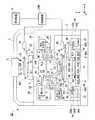
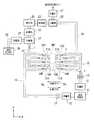
図1は本発明の露光装置の第1実施形態を示す概略構成図である。図1において、露光装置EXは、マスクMを支持するマスクステージMSTと、基板Pを支持する基板ステージPSTと、マスクステージMSTに支持されているマスクMを露光光ELで照明する照明光学系ILと、露光光ELで照明されたマスクMのパターン像を基板ステージPSTに支持されている基板Pに投影露光する投影光学系PLと、露光装置EX全体の動作を統括制御する制御装置CONTとを備えている。制御装置CONTには、露光処理に関して異常が生じたときに警報を発する警報装置Kが接続されている。更に、露光装置EXは、マスクステージMST及び投影光学系PLを支持するメインコラム3を備えている。メインコラム3は、床面に水平に載置されたベースプレート4上に設置されている。メインコラム3には、内側に向けて突出する上側段部3A及び下側段部3Bが形成されている。なお、制御装置は、図23に示したように、露光装置を構成する種々のコンポーネント及び露光装置の外部の関連装置と接続されており、制御装置の制御内容は後述する。<First Embodiment>
FIG. 1 is a schematic block diagram that shows the first embodiment of the exposure apparatus of the present invention. In FIG. 1, an exposure apparatus EX includes a mask stage MST that supports a mask M, a substrate stage PST that supports a substrate P, and an illumination optical system IL that illuminates the mask M supported by the mask stage MST with exposure light EL. A projection optical system PL that projects and exposes the pattern image of the mask M illuminated by the exposure light EL onto the substrate P supported by the substrate stage PST, and a control device CONT that controls the overall operation of the exposure apparatus EX. I have. The control device CONT is connected to an alarm device K that issues an alarm when an abnormality occurs in the exposure process. The exposure apparatus EX further includes a
本実施形態の露光装置EXは、露光波長を実質的に短くして解像度を向上するとともに焦点深度を実質的に広くするために液浸法を適用した液浸露光装置であって、基板P上に液体1を供給する液体供給機構10と、基板P上の液体1を回収する液体回収機構20とを備えている。露光装置EXは、少なくともマスクMのパターン像を基板P上に転写している間、液体供給機構10から供給した液体1により投影光学系PLの投影領域AR1を含む基板P上の一部に、投影領域AR1よりも大きく且つ基板Pよりも小さい液浸領域AR2を局所的に形成する。具体的には、露光装置EXは、投影光学系PLの先端部(終端部)の光学素子2と基板Pの表面との間に液体1を満たし、この投影光学系PLと基板Pとの間の液体1及び投影光学系PLを介してマスクMのパターン像を基板P上に投影することによってこの基板Pを露光する。 The exposure apparatus EX of the present embodiment is an immersion exposure apparatus to which an immersion method is applied in order to improve the resolution by substantially shortening the exposure wavelength and substantially increase the depth of focus. A
本実施形態では、露光装置EXとしてマスクMと基板Pとを走査方向における互いに異なる向き(逆方向)に同期移動しつつマスクMに形成されたパターンを基板Pに露光する走査型露光装置(所謂スキャニングステッパ)を使用する場合を例にして説明する。以下の説明において、投影光学系PLの光軸AXと一致する方向をZ軸方向、Z軸方向に垂直な平面内でマスクMと基板Pとの同期移動方向(走査方向)をX軸方向、Z軸方向及びX軸方向に垂直な方向(非走査方向)をY軸方向とする。また、X軸、Y軸、及びZ軸まわりの回転(傾斜)方向をそれぞれ、θX、θY、及びθZ方向とする。なお、ここでいう「基板」は半導体ウエハ上に感光性材料であるフォトレジストを塗布したものを含み、「マスク」は基板上に縮小投影されるデバイスパターンを形成されたレチクルを含む。 In the present embodiment, the exposure apparatus EX is a scanning exposure apparatus (so-called so-called exposure apparatus EX) that exposes the pattern formed on the mask M onto the substrate P while synchronously moving the mask M and the substrate P in different directions (reverse directions) in the scanning direction. A case where a scanning stepper) is used will be described as an example. In the following description, the direction that coincides with the optical axis AX of the projection optical system PL is the Z-axis direction, the synchronous movement direction (scanning direction) between the mask M and the substrate P in the plane perpendicular to the Z-axis direction is the X-axis direction, A direction (non-scanning direction) perpendicular to the Z-axis direction and the X-axis direction is defined as a Y-axis direction. Further, the rotation (inclination) directions around the X axis, Y axis, and Z axis are the θX, θY, and θZ directions, respectively. Here, the “substrate” includes a semiconductor wafer coated with a photoresist, which is a photosensitive material, and the “mask” includes a reticle on which a device pattern to be reduced and projected on the substrate is formed.
照明光学系ILは、メインコラム3の上部に固定された支持コラム5により支持されている。照明光学系ILは、マスクステージMSTに支持されているマスクMを露光光ELで照明するものであり、露光用光源、露光用光源から射出された光束の照度を均一化するオプティカルインテグレータ、オプティカルインテグレータからの露光光ELを集光するコンデンサレンズ、リレーレンズ系、及び露光光ELによるマスクM上の照明領域をスリット状に設定する可変視野絞り等を有している。マスクM上の所定の照明領域は照明光学系ILにより均一な照度分布の露光光ELで照明される。照明光学系ILから射出される露光光ELとしては、例えば水銀ランプから射出される紫外域の輝線(g線、h線、i線)及びKrFエキシマレーザ光(波長248nm)等の遠紫外光(DUV光)や、ArFエキシマレーザ光(波長193nm)及びF2レーザ光(波長157nm)等の真空紫外光(VUV光)等が用いられる。本実施形態においてはArFエキシマレーザ光が用いられる。The illumination optical system IL is supported by a
本実施形態において、液体1には純水が用いられる。純水はArFエキシマレーザ光のみならず、例えば水銀ランプから射出される紫外域の輝線(g線、h線、i線)及びKrFエキシマレーザ光(波長248nm)等の遠紫外光(DUV光)も透過可能である。 In the present embodiment, pure water is used as the
マスクステージMSTは、マスクMを支持するものであって、その中央部にマスクMのパターン像を通過させる開口部34Aを備えている。メインコラム3の上側段部3Aには、防振ユニット6を介してマスク定盤31が支持されている。マスク定盤31の中央部にも、マスクMのパターン像を通過させる開口部34Bが形成されている。マスクステージMSTの下面には非接触ベアリングである気体軸受(エアベアリング)32が複数設けられている。マスクステージMSTはエアベアリング32によりマスク定盤31の上面(ガイド面)31Aに対して非接触支持されており、リニアモータ等のマスクステージ駆動機構により、投影光学系PLの光軸AXに垂直な平面内、すなわちXY平面内で2次元移動可能及びθZ方向に微小回転可能である。マスクステージMST上にはマスクステージMSTとともに投影光学系PLに対して移動する移動鏡35が設けられている。また、移動鏡35に対向する位置にはレーザ干渉計36が設けられている。マスクステージMST上のマスクMの2次元方向の位置、及びθZ方向の回転角(場合によってはθX、θY方向の回転角も含む)はレーザ干渉計36によりリアルタイムで計測され、計測結果は制御装置CONTに出力される。制御装置CONTは、レーザ干渉計36の計測結果に基づいてマスクステージ駆動機構を駆動することでマスクステージMSTに支持されているマスクMの位置を制御する。 The mask stage MST supports the mask M, and has an
投影光学系PLは、マスクMのパターンを所定の投影倍率βで基板Pに投影露光するものであって、基板P側の先端部に設けられた光学素子(レンズ)2を含む複数の光学素子で構成されており、これら光学素子は鏡筒PKで支持されている。本実施形態において、投影光学系PLは、投影倍率βが例えば1/4あるいは1/5の縮小系である。なお、投影光学系PLは等倍系及び拡大系のいずれでもよい。鏡筒PKの外周部にはフランジ部FLGが設けられている。また、メインコラム3の下側段部3Bには、防振ユニット7を介して鏡筒定盤8が支持されている。そして、投影光学系PLのフランジ部FLGが鏡筒定盤8に係合することによって、投影光学系PLが鏡筒定盤8に支持されている。 The projection optical system PL projects and exposes the pattern of the mask M onto the substrate P at a predetermined projection magnification β, and includes a plurality of optical elements including an optical element (lens) 2 provided at the front end portion on the substrate P side. These optical elements are supported by a lens barrel PK. In the present embodiment, the projection optical system PL is a reduction system having a projection magnification β of, for example, 1/4 or 1/5. Note that the projection optical system PL may be either an equal magnification system or an enlargement system. A flange portion FLG is provided on the outer peripheral portion of the lens barrel PK. A lens
本実施形態の投影光学系PLの先端部の光学素子2は鏡筒PKに対して着脱(交換)可能に設けられている。光学素子2には液浸領域AR2の液体1が接触する。光学素子2は螢石で形成されている。螢石は水との親和性が高いので、光学素子2の液体接触面2aのほぼ全面に液体1を密着させることができる。すなわち、本実施形態においては光学素子2の液体接触面2aとの親和性が高い液体(水)1を供給するようにしているので、光学素子2の液体接触面2aと液体1との密着性が高く、光学素子2と基板Pとの間の光路を液体1で確実に満たすことができる。なお、光学素子2は、水との親和性が高い石英であってもよい。また、光学素子2の液体接触面2aに親水化(親液化)処理を施して、液体1との親和性をより高めるようにしてもよい。 The
光学素子2を囲むようにプレート部材2Pが設けられている。プレート部材2Pの基板Pと対向する面(すなわち下面)は平坦面となっている。光学素子2の下面(液体接触面)2aも平坦面となっており、プレート部材2Pの下面と光学素子2の下面とはほぼ面一となっている。これにより、広い範囲で液浸領域AR2を良好に形成することができる。
また、プレート部材2Pの下面に、光学素子2同様、表面処理(親液化処理)を施すことができる。A
Further, similarly to the
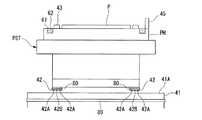
基板ステージ(可動部材)PSTは、基板ホルダ(基板保持部材)PHを介して基板Pを吸着保持して移動可能に設けられており、その下面には複数の非接触ベアリングである気体軸受(エアベアリング)42が設けられている。ベースプレート4上には、防振ユニット9を介して基板定盤41が支持されている。エアベアリング42は、基板定盤41の上面(ガイド面)41Aに対して気体(エア)を吹き出す吹出口42Bと、基板ステージPST下面(軸受面)とガイド面41Aとの間の気体を吸引する吸気口42Aとを備えており、吹出口42Bからの気体の吹き出しによる反発力と吸気口42Aによる吸引力との釣り合いにより、基板ステージPST下面とガイド面41Aとの間に一定の隙間を保持する。つまり、基板ステージPSTはエアベアリング42により基板定盤(ベース部材)41の上面(ガイド面)41Aに対して非接触支持されており、リニアモータ等の基板ステージ駆動機構により、投影光学系PLの光軸AXに垂直な平面内、すなわちXY平面内で2次元移動可能及びθZ方向に微小回転可能である。更に、基板ホルダPHは、Z軸方向、θX方向、及びθY方向にも移動可能に設けられている。基板ステージ駆動機構は制御装置CONTにより制御される。すなわち、基板ホルダPHは、基板Pのフォーカス位置(Z位置)及び傾斜角を制御して基板Pの表面をオートフォーカス方式、及びオートレベリング方式で投影光学系PLの像面に合わせ込むとともに、基板PのX軸方向及びY軸方向における位置決めを行う。 The substrate stage (movable member) PST is provided so as to be movable while adsorbing and holding the substrate P via a substrate holder (substrate holding member) PH, and a gas bearing (air) which is a plurality of non-contact bearings on the lower surface thereof. Bearing) 42 is provided. A
基板ステージPST(基板ホルダPH)上には、基板ステージPSTとともに投影光学系PLに対して移動する移動鏡45が設けられている。また、移動鏡45に対向する位置にはレーザ干渉計46が設けられている。基板ステージPST上の基板Pの2次元方向の位置、及び回転角はレーザ干渉計46によりリアルタイムで計測され、計測結果は制御装置CONTに出力される。制御装置CONTはレーザ干渉計46の計測結果に基づいてリニアモータを含む基板ステージ駆動機構を駆動することで基板ステージPSTに支持されている基板Pの位置決めを行う。 On the substrate stage PST (substrate holder PH), a
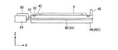
また、基板ステージPST(基板ホルダPH)上には、基板Pを囲むように補助プレート43が設けられている(図2参照)。補助プレート43は基板ホルダPHに保持された基板Pの表面とほぼ同じ高さの平面を有している。基板Pのエッジ領域を露光する場合にも、補助プレート43により投影光学系PLの下に液体1を保持することができる。 An
また、基板ホルダPHのうち補助プレート43の外側には、基板Pの外側に流出した液体1を回収する回収装置60の回収口(吸引口)61が設けられている。回収口61は補助プレート43を囲むように形成された環状の溝部であって、その内部にはスポンジ状部材や多孔質体等からなる液体吸収部材62が配置されている。 In addition, a recovery port (suction port) 61 of a
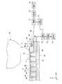
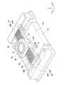
図2は、基板ステージPST及びこの基板ステージPSTを駆動する基板ステージ駆動機構を示す概略斜視図である。図2において、基板ステージPSTは、Xガイドステージ44によりX軸方向に移動自在に支持されている。基板ステージPSTは、Xガイドステージ44に案内されつつXリニアモータ47によりX軸方向に所定ストロークで移動可能である。Xリニアモータ47は、Xガイドステージ44にX軸方向に延びるように設けられた固定子47Aと、この固定子47Aに対応して設けられ基板ステージPSTに固定された可動子47Bとを備えている。そして、可動子47Bが固定子47Aに対して駆動することで基板ステージPSTがX軸方向に移動する。ここで、基板ステージPSTは、Xガイドステージ44に対してZ軸方向に所定量のギャップを維持する磁石及びアクチュエータからなる磁気ガイドにより非接触で支持されている。基板ステージPSTはXガイドステージ44に非接触支持された状態でXリニアモータ47によりX軸方向に移動する。 FIG. 2 is a schematic perspective view showing the substrate stage PST and the substrate stage driving mechanism for driving the substrate stage PST. In FIG. 2, the substrate stage PST is supported by an
Xガイドステージ44の長手方向両端には、このXガイドステージ44を基板ステージPSTとともにY軸方向に移動可能な一対のYリニアモータ48が設けられている。Yリニアモータ48のそれぞれは、Xガイドステージ44の長手方向両端に設けられた可動子48Bと、この可動子48Bに対応して設けられた固定子48Aとを備えている。そして、可動子48Bが固定子48Aに対して駆動することでXガイドステージ44が基板ステージPSTとともにY軸方向に移動する。また、Yリニアモータ48のそれぞれの駆動を調整することでXガイドステージ44はθZ方向にも回転移動可能となっている。したがって、このYリニアモータ48により基板ステージPSTがXガイドステージ44とほぼ一体的にY軸方向及びθZ方向に移動可能となっている。 At both ends in the longitudinal direction of the
基板定盤41のX軸方向両側のそれぞれには、正面視L字状に形成され、Xガイドステージ44のY軸方向への移動を案内するガイド部49が設けられている。ガイド部49はベースプレート4(図1)上に支持されている。本実施形態において、ガイド部49の平坦部49B上に、Yリニアモータ48の固定子48Aが設けられている。一方、Xガイドステージ44の下面の長手方向両端部のそれぞれには凹形状の被ガイド部材50が設けられている。ガイド部49は被ガイド部50と係合し、ガイド部49の上面(ガイド面)49Aと被ガイド部材50の内面とが対向するように設けられている。ガイド部49のガイド面49Aには非接触ベアリングである気体軸受(エアベアリング)51が設けられており、Xガイドステージ44はガイド面49Aに対して非接触支持されている。 On both sides of the
また、Yリニアモータ48の固定子48Aとガイド部49の平坦部49Bとの間には非接触ベアリングである気体軸受(エアベアリング)52が介在されており、固定子48Aはエアベアリング52によりガイド部49の平坦部49Bに対して非接触支持される。このため、運動量保存の法則によりXガイドステージ44及び基板ステージPSTの+Y方向(−Y方向)の移動に応じて固定子48Aが−Y方向(+Y方向)に移動する。この固定子48Aの移動によりXガイドステージ44及び基板ステージPSTの移動に伴う反力が相殺されるとともに重心位置の変化を防ぐことができる。すなわち、固定子48Aは所謂カウンタマスとしての機能を有している。 A gas bearing (air bearing) 52 that is a non-contact bearing is interposed between the
図3は、液体供給機構10、液体回収機構20、及び投影光学系PL先端部近傍を示す拡大図である。液体供給機構10は、投影光学系PLと基板Pとの間へ液体1を供給するものであって、液体1を送出可能な液体供給部11と、液体供給部11に供給管15を介して接続され、この液体供給部11から送出された液体1を基板P上に供給する供給ノズル14とを備えている。供給ノズル14は基板Pの表面に近接して配置されている。液体供給部11は、液体1を収容するタンク、及び加圧ポンプ等を備えており、供給管15及び供給ノズル14を介して基板P上に液体1を供給する。液体供給部11の液体供給動作は制御装置CONTにより制御され、制御装置CONTは液体供給部11による基板P上に対する単位時間あたりの液体供給量を制御可能である。 FIG. 3 is an enlarged view showing the
供給管15の途中には、液体供給部11より基板P上に供給される液体1の量(単位時間あたりの液体供給量)を計測する流量計12が設けられている。流量計12は基板P上に供給される液体1の量を常時モニタし、その計測結果を制御装置CONTに出力する。
また、供給管15のうち流量計12と供給ノズル14との間には、供給管15の流路を開閉するバルブ13が設けられている。バルブ13の開閉動作は制御装置CONTにより制御されるようになっている。なお、本実施形態におけるバルブ13は、例えば停電等により露光装置EX(制御装置CONT)の駆動源(電源)が停止した場合に供給管15の流路を機械的に閉塞する所謂ノーマルオフ方式(ノーマルクローズ方式)となっている。In the middle of the
A
液体回収機構20は、液体供給機構10によって供給された基板P上の液体1を回収するものであって、基板Pの表面に近接して配置された回収ノズル(吸引口)21と、回収ノズル21に回収管24を介して接続された真空系(吸引系)25とを備えている。真空系25は真空ポンプを含んで構成されており、その動作は制御装置CONTに制御される。真空系25が駆動することにより、基板P上の液体1はその周囲の気体(空気)とともに回収ノズル21を介して回収される。なお、真空系25として、露光装置に真空ポンプを設けずに、露光装置EXが配置される工場の真空系を用いるようにしてもよい。 The
回収管24の途中には、回収ノズル21から吸い込まれた液体1と気体とを分離する気液分離器22が設けられている。ここで、上述したように、回収ノズル21からは基板P上の液体1とともにその周囲の気体も回収される。気液分離器22は、回収ノズル21より回収した液体1と気体とを分離する。気液分離器22としては、例えば複数の穴部を有する管部材に回収した液体と気体とを流通させ、液体を重力作用により前記穴部を介して落下させることで液体と気体とを分離する重力分離方式の装置や、回収した液体と気体とを遠心力を使って分離する遠心分離方式の装置等を採用可能である。そして、真空系25は、気液分離器22で分離された気体を吸引するようになっている。 A gas-
回収管24のうち、真空系25と気液分離器22との間には、気液分離器22によって分離された気体を乾燥させる乾燥器23が設けられている。仮に気液分離器22で分離された気体に液体成分が混在していても、乾燥器23により気体を乾燥し、その乾燥した気体を真空系25に流入させることで、液体成分が流入することに起因する真空系25の故障等の不都合の発生を防止することができる。乾燥器23としては、例えば気液分離器22より供給された気体(液体成分が混在している気体)を、その液体の露点以下に冷却することで液体成分を除く方式の装置、例えば冷却器や、その液体の沸点以上に加熱することで液体成分を除く方式の装置、例えばヒーター等を採用可能である。 In the
一方、気液分離器22で分離された液体1は第2回収管26を介して液体回収部28に回収される。液体回収部28は、回収された液体1を収容するタンク等を備えている。液体回収部28に回収された液体1は、例えば廃棄されたり、あるいはクリーン化されて液体供給部11等に戻され再利用される。また、第2回収管26の途中であって気液分離器22と液体回収部28との間には、回収された液体1の量(単位時間あたりの液体回収量)を計測する流量計27が設けられている。流量計27は基板P上から回収された液体1の量を常時モニタし、その計測結果を制御装置CONTに出力する。上述したように、回収ノズル21からは基板P上の液体1とともにその周囲の気体も回収されるが、気液分離器22で液体1と気体とを分離し、液体成分のみを流量計27に送ることにより、流量計27は基板P上より回収した液体1の量を正確に計測可能となる。 On the other hand, the
また、露光装置EXは、基板ステージPSTに支持されている基板Pの表面の位置を検出するフォーカス検出系56を備えている。フォーカス検出系56は、基板P上に液体1を介して斜め上方より検出用光束を投射する投光部56Aと、基板Pで反射した前記検出用光束の反射光を受光する受光部56Bとを備えている。フォーカス検出系56(受光部56B)の受光結果は制御装置CONTに出力される。制御装置CONTはフォーカス検出系56の検出結果に基づいて、基板P表面のZ軸方向の位置情報を検出することができる。また、投光部56Aより複数の検出用光束を投射することにより、基板PのθX及びθY方向の傾斜情報を検出することができる。 Further, the exposure apparatus EX includes a
なお、フォーカス検出系56は、基板Pに限らず、投影光学系PLの像面側に配置された物体の表面位置情報を検出することができる。また、フォーカス検出系56は液体1を介して物体(基板P)の表面位置情報を検出するものであるが、液浸領域AR2の外側で液体1を介さずに物体(基板P)の表面位置情報を検出するフォーカス検出系を採用することもできる。 The
なお、図1の一部断面図に示すように、液体供給機構10及び液体回収機構20は、鏡筒定盤8に対して分離支持されている。これにより、液体供給機構10及び液体回収機構20で生じた振動が、鏡筒定盤8を介して投影光学系PLに伝わることがない。 As shown in the partial cross-sectional view of FIG. 1, the
図4は、液体供給機構10及び液体回収機構20と投影光学系PLの投影領域AR1との位置関係を示す平面図である。投影光学系PLの投影領域AR1はY軸方向に細長い矩形状(スリット状)となっており、その投影領域AR1をX軸方向に挟むように、+X側に3つの供給ノズル14A〜14Cが配置され、−X側に2つの回収ノズル21A、21Bが配置されている。そして、供給ノズル14A〜14Cは供給管15を介して液体供給部11に接続され、回収ノズル21A、21Bは回収管24を介して真空系25に接続されている。また、供給ノズル14A〜14Cと回収ノズル21A、21Bとをほぼ180°回転した位置に、供給ノズル14A’〜14C’と、回収ノズル21A’、21B’とが配置されている。供給ノズル14A〜14Cと回収ノズル21A’、21B’とはY軸方向に交互に配列され、供給ノズル14A’〜14C’と回収ノズル21A、21BとはY軸方向に交互に配列され、供給ノズル14A’〜14C’は供給管15’を介して液体供給部11に接続され、回収ノズル21A’、21B’は回収管24’を介して真空系25に接続されている。なお、供給管15’の途中には、供給管15同様、流量計12’及びバルブ13’が設けられている。また、回収管24’の途中には、回収管24同様、気液分離器22’及び乾燥器23’が設けられている。 FIG. 4 is a plan view showing the positional relationship between the
図5は、基板Pの外側に流出した液体1を回収する回収装置60を示す図である。図5において、回収装置60は、基板ホルダPH上において補助プレート43を囲むように環状に形成された回収口(吸引口)61と、回収口61に配置され、スポンジ状部材や多孔質セラミックス等の多孔質体からなる液体吸収部材62とを備えている。液体吸収部材62は所定幅を有する環状部材であり、液体1を所定量保持可能である。基板ホルダPHの内部には、回収口61と連通する流路63が形成されており、回収口61に配置されている液体吸収部材62の底部は流路63に接触している。また、基板ホルダPH上の基板Pと補助プレート43との間には複数の液体回収孔64が設けられている。これら液体回収孔64も流路63に接続している。 FIG. 5 is a diagram illustrating a
基板Pを保持する基板ホルダ(基板保持部材)PHの上面には、基板Pの裏面を支持するための複数の突出部65が設けられている。これら突出部65のそれぞれには、基板Pを吸着保持するための吸着孔66が設けられている。そして、吸着孔66のそれぞれは、基板ホルダPH内部に形成された管路67に接続している。 On the upper surface of the substrate holder (substrate holding member) PH that holds the substrate P, a plurality of
回収口61及び液体回収孔64のそれぞれに接続されている流路63は、基板ホルダPH外部に設けられている管路68の一端部に接続されている。一方、管路68の他端部は真空ポンプを含む真空系70に接続されている。管路68の途中には気液分離器71が設けられており、気液分離器71と真空系70との間には乾燥器72が設けられている。真空系70の駆動により回収口61から液体1がその周囲の気体とともに回収される。また、液体1が基板Pと補助プレート43との間から浸入して、基板Pの裏面側に回り込んだとしても、その液体は回収口64から周囲の気体とともに回収される。真空系70には、気液分離器71によって分離され、乾燥器72によって乾燥された気体が流入する。一方、気液分離器71によって分離された液体1は、液体1を収容可能なタンク等を備える液体回収部73に流入する。なお、液体回収部73に回収された液体1は、例えば廃棄されたり、あるいはクリーン化されて液体供給部11等に戻され再利用される。 The
また、吸着孔66に接続されている管路67は、基板ホルダPH外部に設けられている管路69の一端部に接続されている。一方、管路69の他端部は、基板ホルダPH外部に設けられた真空ポンプを含む真空系74に接続されている。真空系74の駆動により、突出部65に支持された基板Pは吸着孔66に吸着保持される。管路69の途中には気液分離器75が設けられており、気液分離器75と真空系74との間には乾燥器76が設けられている。また、気液分離器75には、液体1を収容可能なタンク等を備える液体回収部73が接続されている。 Further, the
次に、上述した露光装置EXを用いてマスクMのパターンを基板Pに露光する手順について、図1等を参照しながら説明する。 Next, a procedure for exposing the pattern of the mask M onto the substrate P using the exposure apparatus EX described above will be described with reference to FIG.
マスクMがマスクステージMSTにロードされるとともに、基板Pが基板ステージPSTにロードされた後、制御装置CONTは、液体供給機構10の液体供給部11を駆動し、供給管15及び供給ノズル14を介して単位時間あたり所定量の液体1を基板P上に供給する。また、制御装置CONTは、液体供給機構10による液体1の供給に伴って液体回収機構20の真空系25を駆動し、回収ノズル21及び回収管24を介して単位時間あたり所定量の液体1を回収する。これにより、投影光学系PLの先端部の光学素子2と基板Pとの間に液体1の液浸領域AR2が形成される。ここで、液浸領域AR2を形成するために、制御装置CONTは、基板P上に対する液体供給量と基板P上からの液体回収量とがほぼ同じ量になるように、液体供給機構10及び液体回収機構20のそれぞれを制御する。そして、制御装置CONTは、照明光学系ILによりマスクMを露光光ELで照明し、マスクMのパターンの像を投影光学系PL及び液体1を介して基板Pに投影する。 After the mask M is loaded on the mask stage MST and the substrate P is loaded on the substrate stage PST, the control device CONT drives the
走査露光時には、投影領域AR1にマスクMの一部のパターン像が投影され、投影光学系PLに対して、マスクMが−X方向(又は+X方向)に速度Vで移動するのに同期して、基板ステージPSTを介して基板Pが+X方向(又は−X方向)に速度β・V(βは投影倍率)で移動する。そして、1つのショット領域への露光終了後に、基板Pのステッピングによって次のショット領域が走査開始位置に移動し、以下、ステップ・アンド・スキャン方式で各ショット領域に対する露光処理が順次行われる。本実施形態では、基板Pの移動方向と平行に、基板Pの移動方向と同一方向に液体1を流すように設定されている。
つまり、矢印Xa(図4参照)で示す走査方向(−X方向)に基板Pを移動させて走査露光を行う場合には、供給管15、供給ノズル14A〜14C、回収管24、及び回収ノズル21A、21Bを用いて、液体供給機構10及び液体回収機構20による液体1の供給及び回収が行われる。すなわち、基板Pが−X方向に移動する際には、供給ノズル14(14A〜14C)より液体1が投影光学系PLと基板Pとの間に供給されるとともに、回収ノズル21(21A、21B)より基板P上の液体1がその周囲の気体とともに回収され、投影光学系PLの先端部の光学素子2と基板Pとの間を満たすように−X方向に液体1が流れる。一方、矢印Xb(図4参照)で示す走査方向(+X方向)に基板Pを移動させて走査露光を行う場合には、供給管15’、供給ノズル14A’〜14C’、回収管24’、及び回収ノズル21A’、21B’を用いて、液体供給機構10及び液体回収機構20による液体1の供給及び回収が行われる。すなわち、基板Pが+X方向に移動する際には、供給ノズル14’(14A’〜14C’)より液体1が投影光学系PLと基板Pとの間に供給されるとともに、回収ノズル21’(21A’、21B’)より基板P上の液体1がその周囲の気体ともに回収され、投影光学系PLの先端部の光学素子2と基板Pとの間を満たすように+X方向に液体1が流れる。この場合、例えば供給ノズル14を介して供給される液体1は基板Pの−X方向への移動に伴って光学素子2と基板Pとの間に引き込まれるようにして流れるので、液体供給機構10(液体供給部11)の供給エネルギーが小さくても液体1を光学素子2と基板Pとの間に容易に供給できる。そして、走査方向に応じて液体1を流す方向を切り替えることにより、+X方向、又は−X方向のどちらの方向に基板Pを走査する場合にも、光学素子2と基板Pとの間を液体1で満たすことができ、高い解像度及び広い焦点深度で露光を行うことができる。At the time of scanning exposure, a part of the pattern image of the mask M is projected onto the projection area AR1, and the mask M moves in the −X direction (or + X direction) at the velocity V with respect to the projection optical system PL. Then, the substrate P moves in the + X direction (or -X direction) at a speed β · V (β is the projection magnification) via the substrate stage PST. Then, after the exposure of one shot area is completed, the next shot area is moved to the scanning start position by stepping the substrate P, and thereafter, the exposure process for each shot area is sequentially performed by the step-and-scan method. In the present embodiment, the
That is, when scanning exposure is performed by moving the substrate P in the scanning direction (-X direction) indicated by the arrow Xa (see FIG. 4), the
露光処理中、液体供給機構10に設けられている流量計12の計測結果、及び液体回収機構20に設けられている流量計27の計測結果は、常時、制御装置CONTに出力されている。制御装置CONTは、流量計12の計測結果、すなわち液体供給機構10によって基板P上に供給される液体の量と、流量計27の計測結果、すなわち液体回収機構20によって基板P上より回収された液体の量とを比較し、その比較した結果に基づいて液体供給機構10のバルブ13を制御する。具体的には、制御装置CONTは、基板P上への液体供給量(流量計12の計測結果)と基板P上からの液体回収量(流量計27の計測結果)との差を求め、その求めた差が予め設定されている許容値(しきい値)を越えたかどうかの判断に基づいて、バルブ13を制御する。ここで、上述したように、制御装置CONTは、基板P上に対する液体供給量と基板P上からの液体回収量とがほぼ同じになるように、液体供給機構10及び液体回収機構20のそれぞれを制御しているため、液体供給機構10による液体供給動作及び液体回収機構20による液体回収動作のそれぞれが正常に行われている状況であれば、上記求めた差はほぼゼロとなる。 During the exposure process, the measurement result of the
制御装置CONTは、求めた差が許容値以上である場合、すなわち液体回収量が液体供給量に比べて極端に少ない場合、液体回収機構20の回収動作に異常が生じて十分に液体1を回収できていないと判断する。このとき、制御装置CONTは、例えば液体回収機構20の真空系25に故障等の異常が生じたと判断し、液体回収機構20によって液体1を正常に回収できないことに起因する液体1の漏洩を防止するために、液体供給機構10のバルブ13を作動して供給管15の流路を遮断し、液体供給機構10による基板P上に対する液体1の供給を停止する。このように、制御装置CONTは、液体供給機構10から基板P上に供給された液体量と、液体回収機構20で回収された液体量とを比較し、その比較結果に基づいて液体回収機構20の回収動作の異常を検出し、液体1が供給過剰になり、異常が検出されたときに基板P上に対する液体1の供給を停止する。これにより、基板Pや基板ステージPST(基板ホルダPH)の外側への液体1の漏洩、又は不所望箇所への液体1の浸入、あるいはそのような漏洩や浸入による被害の拡大を防止することができる。 When the calculated difference is equal to or larger than the allowable value, that is, when the liquid recovery amount is extremely small compared to the liquid supply amount, the control unit CONT recovers the liquid 1 sufficiently due to an abnormality in the recovery operation of the
また、制御装置CONTは、液体回収機構20の回収動作の異常を検出したときに、漏洩あるいは浸入した液体1の付着に起因する漏電を防止するために、露光装置EXを構成する電気機器への電力供給を停止する。ここで、電気機器としては、基板ステージPSTを動かすためのリニアモータ47、48等が挙げられる。これらリニアモータ47、48は、基板ステージPSTの外側に漏洩した液体1が付着・浸入しやすい位置にあるため、制御装置CONTは、これらリニアモータ47、48に対する電力供給を停止することで、液体1の付着に起因する漏電を防止することができる。また、電気機器としては、リニアモータ47、48の他に、例えば基板ステージPST上に設けられ、基板ステージPSTに対する露光光ELを受光するためのセンサ(フォトマルなど)が挙げられる。あるいは電気機器として、基板ホルダPHのZ軸方向及び傾斜方向の位置調整をするための例えばピエゾ素子等の各種アクチュエータが挙げられる。また、異常を検出したときに、露光装置EXを構成する全ての電気機器への電力供給を停止することも可能であるし、一部の電気機器への電力供給を停止することも可能である。ここで、制御装置CONTは、液体回収機構20の回収動作の異常を検出したときに、例えばリニアモータや、0〜150V付近で使用されるピエゾ素子や、300〜900V付近で使用されるフォトマル(センサ)などの電気機器(高電圧機器)に対する電力供給を停止することで、漏電の発生を防止し、漏電に起因する周辺装置に対する影響を抑えることができる。 In addition, when the control device CONT detects an abnormality in the recovery operation of the
また、制御装置CONTは、液体回収機構20の回収動作の異常を検出したときに、例えば基板ステージPSTを基板定盤41のガイド面41Aに対して非接触で移動させるためのエアベアリング42の駆動を停止する。エアベアリング42は、基板定盤41の上面(ガイド面)41Aに対して気体(エア)を吹き出す吹出口42Bと、基板ステージPST下面(軸受面)とガイド面41Aとの間の気体を吸引する吸気口42Aとを備えており、吹出口42Bからの気体の吹き出しによる反発力と吸気口42Aによる吸引力との釣り合いにより、基板ステージPST下面とガイド面41Aとの間に一定の隙間を保持するようになっているが、制御装置CONTは、液体回収機構20の回収動作の異常を検出したときに、漏洩した液体1がエアベアリング42の吸気口42Aに流入(浸入)することを防止するために、エアベアリング42の動作、特に吸気口42Aからの吸気を停止する。
これにより、その吸気口42Aに接続する真空系に対して液体1が流入することを防止でき、液体1の流入に起因する真空系の故障等の不都合の発生を防止できる。Further, when the control device CONT detects an abnormality in the recovery operation of the
Thereby, it is possible to prevent the liquid 1 from flowing into the vacuum system connected to the
また、基板Pを保持する突起部65や吸着孔66を別部材に設けて、その別部材を基板ホルダPHに吸着保持している場合には、制御装置CONTがその別部材を吸着保持するための吸着孔(吸気口)からの吸気を停止するようにしてもよい。 Further, when the
また、制御装置CONTは、液体回収機構20の回収動作の異常を検出したときに、警報装置Kを駆動する。警報装置Kは、警告灯、アラーム音、ディスプレイなどを使って警報を発し、これにより、例えば作業者は、露光装置EXに液体1の漏洩や浸入が発生したことを知ることができる。 Further, the control device CONT drives the alarm device K when detecting an abnormality in the recovery operation of the
また、液体回収機構20の回収動作の異常を検出したとき、制御装置CONTは、回収装置60の液体回収量を多くする。具体的には、回収装置60の真空系70の駆動量(駆動力)を上昇する。回収装置60(真空系70)の駆動は振動源となるため、露光処理中においては、回収装置60の駆動力を低下あるいは停止していることが好ましいが、液体回収機構20の回収動作の異常を検出し、液体1の漏洩の可能性が生じたとき、制御装置CONTは、回収装置60の駆動力を上昇することで、基板ステージPST(基板ホルダPH)の外側(少なくとも回収口61より外側)への液体1の漏洩を防止、あるいは漏洩の拡大を防止することができる。 Further, when an abnormality in the recovery operation of the
また、基板Pの中央付近のショット領域を露光している間は、液体供給機構10から供給された液体1は液体回収機構20により回収される。一方、図5に示すように、基板Pのエッジ領域を露光処理することによって、液浸領域AR2が基板Pのエッジ領域付近にあるとき、補助プレート43により投影光学系PLと基板Pとの間に液体1を保持し続けることができるが、流体1の一部が補助プレート43の外側に流出する場合があり、流出した流体1は、液体吸収部材62を配置した回収口61より回収される。ここで、制御装置CONTは、上記液体供給機構10及び液体回収機構20の駆動開始とともに、回収装置60の動作を開始している。したがって、回収口61より回収された液体1は、真空系70の吸引により、周囲の空気とともに流路63及び管路68を介して回収される。また、基板Pと補助プレート43との隙間に流入した液体1は、液体回収孔64を介して周囲の空気とともに流路63及び管路68を介して回収される。このとき、気液分離器71は、回収口61から回収された液体1と気体とを分離する。気液分離器71によって分離された気体は乾燥器72で乾燥された後に真空系70に流入する。これにより、真空系70に液体成分が流入する不都合を防止できる。一方、気液分離器71によって分離された液体は液体回収部73に回収される。 Further, while the shot region near the center of the substrate P is exposed, the
なおこのとき、回収装置60により液体供給機構10から供給された液体1の一部が回収されるため、液体回収機構20により回収される液体量が減少し、その結果、液体回収機構20の流量計27で計測される液体回収量が減少する。この場合、液体1が漏洩していないにもかかわらず、制御装置CONTは、液体供給機構10の流量計12及び液体回収機構20の流量計27それぞれの計測結果を比較した結果に基づいて、液体回収機構20の回収動作に異常が生じたと誤った判断を下す可能性がある。そこで、回収装置60のうち気液分離器71と液体回収部73との間に回収した液体の量を計測する流量計を設けておき、制御装置CONTは、その回収装置60の流量計の計測結果と液体回収機構20の流量計27の計測結果とに基づいて全体の液体回収量を求め、求めた全体の液体回収量と液体供給機構10の流量計12の計測結果とを比較する。そして、その比較した結果に基づいて、制御装置CONTは、液体回収機構20の液体回収動作に異常が生じたかどうかを判断し、その判断した結果に基づいて、液体供給機構10による液体供給動作の停止、電力供給の停止、吸気口から吸気動作の停止などの対処を実行することができる。 At this time, since a part of the liquid 1 supplied from the
また、回収装置60に設けられた流量計の計測値が予め設定された許容値に対して過剰に大きい値となったとき、制御装置CONTは、多量の液体1が基板Pの外側に流出していると判断し、液体1の基板ステージPST(基板ホルダPH)の外側への漏洩などを防止するために、液体供給機構10を停止するようにしてもよい。 Further, when the measured value of the flow meter provided in the
基板Pの外側に流出した液体1は、基板Pと補助プレート43との隙間から浸入して基板Pの裏面側に達する場合も考えられる。そして、基板Pの裏面側に入り込んだ液体1が基板Pを吸着保持するための吸着孔(吸引口)66に流入する可能性もある。この場合、基板Pを吸着保持するために基板ホルダPHに設けられている吸着孔66は、管路67及び管路69を介して真空系74に接続され、その途中には気液分離器75、及び気液分離器75で分離された気体を乾燥する乾燥器76が設けられている。したがって、仮に吸着孔66に液体1が流入しても、吸着孔66から流入した液体1は液体回収部73に回収され、真空系74に液体成分が流入する不都合を防止することができる。 The liquid 1 that has flowed out of the substrate P may enter the gap between the substrate P and the
なお、吸着孔66から液体1が浸入した場合には基板Pの保持などに不具合が生じる可能性があるので、管路69あるいは気液分離器75と液体回収部73との間に流量計を配置して、その流量計によって吸着孔66からの液体の浸入が検知された場合には異常事態と判断して、上述のような液体供給動作の停止、電力供給停止、吸気口からの吸気の停止の少なくとも一つを実行することもできる。 If the
なお、吸着孔66に接続する管路69に気液分離器75が設けられていない構成の場合は、液体回収機構20や回収装置60の回収動作の異常を検出したときに、吸着孔(吸気口)66への液体1の流入を防止するために、真空系74(吸引系)の駆動を停止して吸着孔66からの吸気を停止するようにしてもよい。 In the case where the gas-
以上説明したように、液体1が漏洩あるいは浸入するような異常を検出したときに、液体供給機構10による基板P上への液体1の供給を停止するようにしたので、液体1の漏洩を防止、あるいは漏洩の拡大や浸水などを防止することができる。また、液体1が漏洩あるいは浸入するような異常が起きた場合でも、露光装置EXを構成するリニアモータ47、48をはじめとする電気機器への電力供給を停止することで、漏電の発生や漏電による被害の拡大を防止することができる。また、エアベアリング42の吸気口42Aや、基板Pを吸着保持するために基板ホルダPHに設けられた吸着孔66等の真空系に流通する各吸気口からの吸気を停止することで、この吸気口に接続する真空系に対して液体1が流入するといった不都合の発生を防止することができる。また、回収ノズル21や回収口61、あるいは吸着孔66等の吸引口から液体とともにその周囲の気体を回収する際、吸引口から吸い込まれた液体と気体とを気液分離器で気液分離し、気液分離器によって分離した気体を更に乾燥器で乾燥することにより、真空系に対して液体成分(湿った気体など)が流入する不都合を防止でき、液体が真空系に与える影響を抑えることができる。また、本実施形態は、吸引口から液体をその周囲の気体とともに回収する構成であるが、気液分離器によって回収した液体と気体とを分離することにより、回収した液体量を正確に計測することができる。 As described above, since the supply of the liquid 1 onto the substrate P by the
なお、上述の実施形態において、液体回収機構20の回収動作の異常として、真空系25の故障(動作異常)を例にして説明したが、真空系25の故障の他に、例えば気液分離器22の動作異常も挙げられる。つまり、回収ノズル21を介して基板P上の液体1を回収できたとしても、気液分離器22が回収ノズル21より回収した液体と気体とを十分に分離できず、流量計27で計測される液体量が所定値より少なくなる状況が生じることが考えられる。この場合、真空系25に流入する液体成分が多くなるので、真空系25の故障等を招くため、制御装置CONTは、液体供給機構10の液体供給動作を停止するとともに、液体回収機構20(真空系25)の液体回収動作を停止することで、液体1の漏洩を防止できるとともに、真空系25の故障を防止することもできる。 In the above-described embodiment, the abnormality in the vacuum system 25 (abnormal operation) has been described as an example of the recovery operation of the
なお、上述の実施形態において、制御装置CONTは、基板P上に対する液体供給量と基板P上からの液体回収量とがほぼ同じになるように、液体供給機構10及び液体回収機構20のそれぞれを制御している。そのため、液体供給機構10による液体供給動作及び液体回収機構20による液体回収動作のそれぞれが正常に行われている状況であれば、上記求めた差はほぼゼロであり、上記許容値はそれに応じて小さい値に予め設定される。一方で、例えば使用する液体1が高い揮発性を有している場合、液体供給機構10による液体供給動作及び液体回収機構20による液体回収動作のそれぞれが正常に行われている状況であっても、基板P上において液体1が揮発し、液体回収機構20の流量計27による計測値が液体供給機構10の流量計12による計測値に対して小さくなることが考えられる。したがって、制御装置CONTは、使用する液体1(揮発性)あるいは基板Pのおかれている環境に応じて、上記許容値を予め設定し、設定した許容値と上記求めた差との比較結果に基づいて、バルブ13を制御すればよい。 In the above-described embodiment, the control device CONT controls each of the
また、上述の実施形態においては、液体供給機構10の液体の供給量と液体回収機構20による液体の回収量とを比較して、液体1の流通状態の異常を見地しているが、液体供給機構10の供給量のみ、あるいは液体回収機構20による回収量のみに基づいて、それぞれの異常を検知するようにしてもよい。また、液体の流量に限らず、液体供給機構10や液体回収機構20の機械的あるいは電気的な異常が検知された場合にも、制御装置CONTは液体供給機構10による液体供給動作の停止、電力供給の停止、吸気口から吸気動作の停止などの対処を実行することができる。 In the above-described embodiment, the liquid supply amount of the
上述の実施形態では、回収ノズル21からは液体1とともにその周囲の気体も回収されるため、より正確な液体回収量を計測するために、気液分離器22を使って回収した液体と気体とを分離し、分離した液体量を流量計27で計測するようにしている。そのため、気液分離器22の気液分離能力によっても、流量計27で計測される液体量が変動する可能性がある。そこで、制御装置CONTは、使用する気液分離器22(気液分離能力)に応じて、上記許容値を設定することもできる。 In the above-described embodiment, since the
なお、上述の実施形態において、液体回収機構20の液体回収動作の異常が検出されたときに、液体供給機構10による液体供給動作の停止、電気機器への電力供給の停止、及び吸気口からの吸気動作の停止を全て行うように説明したが、少なくともいずれか1つを実行する構成であってもよい。 In the above-described embodiment, when an abnormality in the liquid recovery operation of the
なお、上述の実施形態において、液体回収機構20の回収ノズル21からは、液体1とともにその周囲の気体も回収するため、流量計27で回収した液体量を精度良く計測可能とするために、気液分離器22を使って液体と気体とに分離する構成であるが、液体回収機構20が、回収ノズル21から液体1のみを回収する構成である場合、気液分離器22で液体と気体とを分離することなく、回収した液体の圧力を測定することによって、液体回収量を求めることができる。 In the above-described embodiment, the
ところで、上述の実施形態では、液体回収機構20の回収動作の異常が検出されたときに、液体供給機構10による液体供給動作を停止したり、電気機器への電力供給を停止したり、吸気口からの吸気動作を停止する構成であるが、基板Pを保持して移動可能な基板ステージ(可動部材)PSTと投影光学系PLとの位置関係の異常が検出されたときに、液体供給動作の停止、電力供給の停止、及び吸気口からの吸気動作の停止のうちの少なくともいずれか1つを実行するようにしてもよい。ここで、基板ステージPSTと投影光学系PLとの異常な位置関係とは、投影光学系PLの下に液体1を保持できない状態であり、Z軸方向及びXY方向のうちの少なくとも一方の位置関係の異常を含む。つまり、たとえ液体供給機構10の供給動作と液体回収機構20の回収動作が正常であっても、例えば基板ステージPSTの動作に異常が生じ、基板ステージPSTが投影光学系PLに対する所望位置に対してXY方向に関してずれた位置に配置された場合、投影光学系PLと基板ステージPSTに保持された基板Pとの間に液体1の液浸領域AR2が良好に形成できない状態(投影光学系PLの下に液体1を保持できない状態)が生じる。この場合、液体1が基板Pの外側、基板ホルダPHの外側に漏洩したり、基板ステージPST(基板ホルダPH)の移動鏡45が浸水する状況が発生する。すると、液体回収機構20は所定量の液体1を回収できないため、液体回収機構20の流量計27は所定値に対して少ない値の計測結果を制御装置CONTに出力する。制御装置CONTは、その流量計27の計測結果に基づいて、液体1の漏洩などが発生するような基板ステージPSTの位置の異常を検出することができる。そして、制御装置CONTは、その異常を検出したときに、液体供給動作の停止、電力供給の停止、及び吸気口からの吸気動作の停止等を実行する。 By the way, in the above-described embodiment, when an abnormality in the recovery operation of the
また、液浸領域AR2は、投影光学系PLと基板Pとの間の距離を、液体1の表面張力により液浸領域AR2を形成可能な程度の所定距離(0.1mm〜1mm程度)に設定することで形成されるが、例えば、基板ステージPSTがZ軸方向に関して位置制御に不具合が生じた場合、投影光学系PLと基板ステージPST上の基板Pとの距離が大きくなり、投影光学系PLの下に液体1を保持できなくなる状況が生じ得る。この場合も、基板Pの外側や基板ステージPST(基板ホルダPH)の外側に液体1が漏洩するなどし、液体回収機構20は所定量の液体1を回収できないため、液体回収機構20の流量計27は所定値に対して少ない値の計測結果を制御装置CONTに出力する。制御装置CONTは、その流量計27の計測結果に基づいて、液体1の漏洩が発生するような基板ステージPSTの位置の異常を検出することができる。そして、制御装置CONTは、その異常を検出したときに、液体供給動作の停止、電力供給の停止、及び吸気口からの吸気動作の停止等を実行する。 Further, in the liquid immersion area AR2, the distance between the projection optical system PL and the substrate P is set to a predetermined distance (about 0.1 mm to 1 mm) that allows the liquid immersion area AR2 to be formed by the surface tension of the
なお、投影光学系PLに対する基板ステージPSTの位置関係の異常を検出するために、液体回収機構20の流量計27の計測結果を用いずに、例えば干渉計46により基板ステージPSTのXY方向の位置を検出し、その位置検出結果に基づいて、位置関係の異常を検出することができる。制御装置CONTは、干渉計46による基板ステージ位置検出結果と予め設定されている許容値とを比較し、干渉計46のステージ位置検出結果が前記許容値を超えたときに、液体1の供給動作の停止等を実行するようにしてもよい。また、フォーカス検出系56により基板ステージPSTのZ軸方向の位置を検出し、フォーカス検出系56によるステージ位置検出結果と予め設定されている許容値とを比較し、フォーカス検出系56の検出結果が許容値を超えたときに、制御装置CONTは、液体1の供給動作の停止等を実行するようにしてもよい。このように、制御装置CONTは、干渉計46及びフォーカス検出系56を含む基板ステージ位置検出装置の検出結果に基づいて、投影光学系PLと基板ステージPSTとの位置関係の異常を検出し、異常が検出されたときに、液体供給動作の停止、電気機器に対する電力供給の停止、及び吸気口からの吸気動作の停止等を実行することができる。 In order to detect an abnormality in the positional relationship of the substrate stage PST with respect to the projection optical system PL, the position of the substrate stage PST in the XY direction is detected by, for example, the
また、干渉計46がエラーを発生したときに、制御装置CONTは、液体供給機構10による液体供給動作を停止するようにしてもよい。ここで、干渉計46のエラーとは、干渉計46自体の故障や、干渉計の測定光の光路上に異物が配置されたなど何らかの原因で基板ステージPSTの位置計測を行うことができなくなった状態を含む。干渉計46がエラーを発生すると、制御装置CONTは、基板ステージPSTの位置を把握することができず、同時に基板ステージPSTの位置を制御することができなくなる。この場合、投影光学系PLと基板ステージPSTとの位置関係に異常が生じ、液体1が漏洩・流出するおそれがある。そこで、干渉計46がエラーを発生したときに、液体供給機構10による液体供給を停止することで、液体1が漏洩する不都合を防止することができる。
同様に、基板ステージPSTのZ軸方向の位置を制御するための計測系(本実施形態においてはフォーカス検出系56)がエラーを発生した場合に、投影光学系PLと基板ステージPSTとの位置関係に異常が生じて、液体1が漏洩・流出する虞があるので、制御装置CONTはフォーカス検出56がエラーを発生した場合に、液体供給機構10による液体供給動作を停止することができる。Further, when the
Similarly, when the measurement system for controlling the position of the substrate stage PST in the Z-axis direction (in this embodiment, the focus detection system 56) generates an error, the positional relationship between the projection optical system PL and the substrate stage PST. Therefore, the control device CONT can stop the liquid supply operation by the
なお、基板ステージPST(基板ホルダPH)と投影光学系PLとのZ軸方向の位置関係の異常は、フォーカス検出系56に限らず、静電容量センサなどの非光学式の検出系を用いるようにしてもよい。 The abnormality in the positional relationship in the Z-axis direction between the substrate stage PST (substrate holder PH) and the projection optical system PL is not limited to the
また、投影光学系PLの像面と基板ステージPST(基板P)表面との位置関係を、干渉計を用いて管理することもできる。なお、投影光学系PLの像面と機基板ステージPST(基板P)表面との位置関係の管理を干渉計を用いて行うことは、例えばUSP6,020,964に開示されており、本国際出願で指定または選択された国の法令で許容される限りにおいて、それらの開示を援用して本文の記載の一部とする。 The positional relationship between the image plane of the projection optical system PL and the surface of the substrate stage PST (substrate P) can also be managed using an interferometer. The management of the positional relationship between the image plane of the projection optical system PL and the surface of the machine substrate stage PST (substrate P) using an interferometer is disclosed in US Pat. No. 6,020,964, for example. To the extent permitted by the laws and regulations of the countries designated or selected in the above, the disclosure thereof is incorporated into the text.
また、上述の実施形態では、露光動作中に異常が生じた場合を説明したが、基板Pの露光を行っていないときに異常が発生した場合も同様である。 In the above-described embodiment, the case where an abnormality occurs during the exposure operation has been described. However, the same applies to the case where an abnormality occurs when the substrate P is not exposed.
また、上述の実施形態では、液体の供給中に異常が検出されたときに液体の供給を停止するようにしたが、液体の供給を開始するときに、投影光学系PLと基板ステージPSTとの位置関係などの異常が検出された場合にも、液体の供給開始を停止するようにするとよい。 In the above-described embodiment, the supply of the liquid is stopped when an abnormality is detected during the supply of the liquid. However, when the supply of the liquid is started, the projection optical system PL and the substrate stage PST Even when an abnormality such as a positional relationship is detected, the liquid supply start may be stopped.
<第2実施形態>
次に、本発明の露光装置EXの第2実施形態について説明する。以下の説明において、上述した実施形態と同一又は同等の構成部分については同一の符号を付し、その説明を簡略若しくは省略する。本実施形態では、基板Pあるいは基板ステージPST(基板ホルダPH)の外側などへの液体1の漏れを光ファイバを含む検出器を使って光学的に検出し、液体1の漏れや浸入を検出したときに、液体供給機構10による液体供給動作の停止、電気機器への電力供給の停止、及び吸気口からの吸気動作の停止のうちの少なくとも1つを実行する。Second Embodiment
Next, a second embodiment of the exposure apparatus EX of the present invention will be described. In the following description, the same or equivalent components as those in the above-described embodiment are denoted by the same reference numerals, and the description thereof is simplified or omitted. In the present embodiment, leakage of the liquid 1 to the outside of the substrate P or the substrate stage PST (substrate holder PH) is optically detected using a detector including an optical fiber, and leakage or intrusion of the
図6及び図7を参照しながら、液体1の漏れを検出する検出器の検出原理について説明する。本実施形態では検出器として光ファイバを用いる。図6は一般的な光ファイバを示す概略構成図である。図6において、光ファイバ80’は、光を伝搬するコア部81と、コア部81の周囲に設けられ、コア部81より小さい屈折率を有するクラッド部82とを備えている。光ファイバ80’では、光はクラッド部82より高い屈折率を有するコア部81に閉じ込められて伝搬される。 The detection principle of the detector that detects the leakage of the
図7は、本実施形態に係る光ファイバ80を示す概略構成図である。図7において、光ファイバ80は、光を伝搬するコア部81を有しており、その周囲にはクラッド部が設けられていない光ファイバ(クラッドレスファイバ)である。光ファイバ80のコア部81は、その周囲の気体(本実施形態では空気)の屈折率naより高い屈折率ncを有し、且つ液体(本実施形態では純水)1の屈折率nwより低い屈折率を有している(na<nc<nw)。そのため、光ファイバ80の周囲が空気で満たされている場合、光の入射角θ0が全反射条件sinθ0>na/ncを満たしている限り、光は空気より高い屈折率ncを有するコア部81に閉じ込められて伝搬される。つまり、光ファイバ80の入射端部から入射した光はその光量を大きく減衰せずに射出端部より射出する。ところが、液体(純水)1が光ファイバ80の表面に付着した場合、nc<nwであるので、水が付着している箇所ではいずれの入射角でも全反射条件sinθ0=nw/ncを満たすことができず、その液体1と光ファイバ80との界面で全反射が生じないため、光は光ファイバ80の液体付着部分から外部に漏洩する。したがって、光ファイバ80の入射端部から入射した光の光量は射出端部より射出する際に減少している。そこで、露光装置EXの所定位置にこの光ファイバ80を設置しておき、この光ファイバ80の射出端部の光量を計測することで、制御装置CONTは、光ファイバ80に液体1が付着したかどうか、つまり液体1が漏洩したかどうかを検出することができる。なお、空気の屈折率は1程度であり、水の屈折率は1.4〜1.6程度であるため、コア部81は例えば1.2程度の屈折率を有する材料(石英、特定組成のガラス等)により構成されていることが好ましい。FIG. 7 is a schematic configuration diagram showing an
また、光ファイバ80の射出端部より射出する光の減衰量によって、光ファイバ80に付着した液体1の量についても求めることができる。すなわち、光の減衰量は光ファイバに液体1が付着している部分の面積に依存し、光ファイバ80の周囲に少量の液体1が付着した場合には射出端部における光の減衰量は小さく、大量の液体1が付着した場合には減衰量は大きい。したがって、液体1が付着している部分の面積は液体の漏洩量に依存すると考えられるので、光ファイバ80の射出端部における光量を計測することによって、液体1の漏洩量を求めることができる。更に、光ファイバ射出端部における光量の計測値を予め設定した複数のしきい値(基準値)と比較し、各しきい値を越えた場合にそれぞれ特定の信号を発するようにすることにより、液体1の漏洩量を段階的に検出することができる。 Further, the amount of the liquid 1 adhering to the
図8は、上記検出器の光ファイバ80を基板ステージPST(基板ホルダPH)の周囲に配置した状態を示す側面図であり、図9は平面図である。図8及び図9に示すように、光ファイバ80は、基板ステージPST(基板ホルダPH)の周囲を巻くように配置されている。そして、光ファイバ80の入射端部には、光ファイバ80に対して光を入射可能な投光部83が接続され、光ファイバ80の射出端部には、光ファイバ80を伝搬して射出端部より射出した光を受光可能な受光部84が接続されている。制御装置CONTは、投光部83から光ファイバ80に入射したときの光の光量と、受光部84で受光した光の光量とに基づいて、光ファイバ80の入射端部に対する射出端部の光の減衰率を求め、その求めた結果に基づいて、光ファイバ80に液体1が付着したかどうか、すなわち基板ステージPST(基板ホルダPH)の外側に液体1が漏洩したかどうかを判断する。そして、制御装置CONTは、液体1が漏洩したと判断したとき、液体供給機構10による液体の供給動作の停止、電気機器に対する電力供給の停止、及び吸気口からの吸気動作の停止等を実行する。 FIG. 8 is a side view showing a state in which the
なお、光ファイバ80を基板ステージPST(基板ホルダPH)の上面、特に回収口61の周りに配置するようにしてもよいし、移動鏡45の浸水(浸液)をチェックするために、移動鏡45またはその周囲に配置してもよい。 The
図10は、光ファイバ80を、基板ステージPSTの下面に設けられたエアベアリング42の周囲、及び基板ステージPSTを移動可能に支持する基板定盤(ベース部材)41の周囲に配置した例を示す図である。光ファイバ80は任意に屈曲可能であるため、基板ステージPST(基板ホルダPH)、エアベアリング42、及び基板定盤41等の液体1が漏洩し易い任意の位置に巻きつけるようにして取り付けることができ、自由に引き回して任意の形態で配置可能である。特に、エアベアリング42の周りに光ファイバ80を取り付けることで、エアベアリング42近傍に液体1が付着(漏洩)したかどうかを良好に検出することができ、エアベアリング42の吸気口42Aに液体1が流入する不都合を未然に防止することができる。 FIG. 10 shows an example in which the
ところで、上述した光ファイバ80においては、入射端から射出端までの距離が長いと、光ファイバ80に液体1が付着した位置、すなわち液体1の漏洩位置を特定することが困難な場合がある。そこで、図11に示すように、複数の光ファイバ80をマトリクス状に2次元的に配置することによって、液体1の漏洩位置を特定することができる。図11において、検出器90は、第1の方向(Y軸方向)を長手方向とし、第1の方向と直交する第2の方向(X軸方向)に複数並んで設けられた第1光ファイバ80Aと、第2の方向を長手方向とし、第1の方向に複数並んで設けられた第2光ファイバ80Bとを備えている。これら複数の第1、第2光ファイバ80A、80Bがマトリクス状(網目状)に配置されている。複数の第1光ファイバ80Aそれぞれの入射端部は集合しており、その集合部と集合ファイバ85Aの射出端部とが接続されている。そして、集合ファイバ85Aの入射端部は投光部83Aに接続されている。一方、複数の第1光ファイバ80Aそれぞれの射出端部は、例えば1次元CCDラインセンサ等からなる受光部84Aに接続されている。同様に、複数の第2光ファイバ80Bそれぞれの入射端部は集合しており、その集合部と集合ファイバ85Bの射出端部とが接続されている。そして、集合ファイバ85Bの入射端部は投光部83Bに接続されている。一方、複数の第2光ファイバ80Bそれぞれの射出端部は、例えば1次元CCDラインセンサ等からなる受光部84Bに接続されている。 Incidentally, in the
投光部83Aから射出された光は、集合ファイバ85Aを伝搬した後、複数の第1光ファイバ80Aのそれぞれに分岐される。第1光ファイバ80Aそれぞれの入射端部から入射した光は、第1光ファイバ80Aを伝搬した後、射出端部より射出され、受光部84Aに受光される。受光部84Aは複数の第1光ファイバ80Aそれぞれの射出端部より射出された光の光量のそれぞれを検出する。ここで、図11に示すように、複数の第1光ファイバ80Aのうち特定の第1光ファイバ80AL上に液体1が付着している場合、その第1光ファイバ80ALの射出端部での光量が低下する。受光部84Aの受光結果は制御装置CONTに出力される。同様に、投光部83Bから射出された光は、集合ファイバ85Bを伝搬した後、複数の第2光ファイバ80Bのそれぞれに分岐される。第2光ファイバ80Bそれぞれの入射端部から入射した光は、第2光ファイバ80Bを伝搬した後、射出端部より射出され、受光部84Bに受光される。受光部84Bは複数の第2光ファイバ80Bそれぞれの射出端部より射出された光の光量のそれぞれを検出する。ここで、図11に示すように、複数の第2光ファイバ80Bのうち特定の第2光ファイバ80BL上に液体1が付着している場合、その第2光ファイバ80BLの射出端部での光量が低下する。
受光部84Bの受光結果は制御装置CONTに出力される。制御装置CONTは、受光部84A、84Bそれぞれの受光結果に基づいて、液体1の漏洩位置(検出器90に対して漏洩した液体1が付着した位置)が、第1光ファイバ80ALと第2光ファイバ80BLとの交点付近であることを特定することができる。The light emitted from the
The light reception result of the
図12は、マトリクス状に配置された光ファイバ80A、80Bを有する検出器90が、基板ステージPSTを駆動する電磁駆動源であるリニアモータ47(固定子47A)に配置されている例を示す図である。検出器90をリニアモータ47に配置することにより、基板ステージPSTの外側に漏洩し、リニアモータ47上に付着した液体1の位置を特定することができる。漏洩した液体1の位置が特定されることにより、例えば漏洩した液体1の除去作業を効率良く行うことができる。 FIG. 12 is a diagram showing an example in which
なお、液体1が水であってその漏洩した液体(水)を除去する場合、無水アルコールを使って除去作業(拭き取り作業)を行うことにより、水を良好に除去することができ、またアルコールは直ちに揮発するため、除去作業を円滑に行うことができる。 In addition, when the
なお、図13に示す模式図のように、光ファイバ80の入射端部よりパルス光を入射することで、光ファイバ80の表面に付着した液体1の位置を特定することができる。光ファイバ80の表面に液体1が付着している場合、光ファイバ80の入射端部から入射したパルス光L1が液体1の付着位置で反射し、その反射光L2が再び入射端部側に戻ってくる現象が生じる。そこで、入射側に偏光ビームスプリッターなどの光学素子を設け、反射光を光学素子で受光器に導いて検出する。検出結果から、パルス光L1を光ファイバ80に入射したタイミングと反射光L2が入射端部で受光されるタイミングとの時間差、及び光ファイバ80を伝搬する光速度に基づいて、入射端部と液体1の付着位置との距離を求めることができ、これにより液体1の付着位置(液体1の漏洩位置)を特定することができる。なお、光ファイバ80を伝搬する光速度は、光ファイバ80(コア部81)の形成材料に応じて変化するため、この光ファイバ80の形成材料に基づいて求めることができる。 As shown in the schematic diagram of FIG. 13, the position of the liquid 1 attached to the surface of the
<第3実施形態>
次に、本発明の露光装置EXの第3実施形態について説明する。本実施形態では、液体1の漏れをプリズム(光学素子)を含む検出器を使って光学的に検出し、液体1の漏れを検出したときに、液体供給機構10による液体供給動作の停止、電気機器への電力供給の停止、及び吸気口からの吸気動作の停止のうちの少なくとも1つを実行する。<Third Embodiment>
Next, a third embodiment of the exposure apparatus EX of the present invention will be described. In this embodiment, the leakage of the
図14及び図15を参照しながら、液体1の漏れを検出する検出器の検出原理について説明する。本実施形態では検出器としてプリズムを用いる。図14は、プリズムを使った検出器100の概略構成を示す図である。図14において、検出器100は、プリズム101と、プリズム101の第1面101Aに取り付けられ、プリズム101に対して光を投射する投光部102と、プリズム101の第2面101Bに取り付けられ、投光部102から射出された光のプリズム101の第3面101Cでの反射光を受光する受光部103とを備えている。なお、第1面101Aと第2面101Bとはほぼ直角となっている。 The detection principle of the detector that detects the leakage of the
プリズム101は、その周囲の気体(本実施形態では空気)より高い屈折率を有し、且つ液体(本実施形態では純水)1より低い屈折率を有している。そして、プリズム101の周囲が空気で満たされている場合、投光部102から第3面101Cに投射された光は、第3面101Cで全反射するようにプリズムの屈折率が選定されている。そのため、投光部102から射出した光はその光量を大きく減衰せずに受光部103に受光される。 The
図15は、検出器100のプリズム101の第3面101Cに液体1が付着した状態を示す図である。図15において、投光部102から第3面101Cに投射された光は、液体1の存在により第3面101Cで全反射せず、一部(又は全部)の光成分がプリズム101の液体付着部分から外部に漏洩する。そのため、投光部102から射出した光のうち第2面101Bに達する光成分の光量が減衰するため、受光部103は、受光した光量(光情報)に基づいて、プリズム101の第3面101Cに液体1が付着したかどうかを検出することができる。そこで、露光装置EXの所定位置にこのプリズム101を備えた検出器100を設置しておくことで、制御装置CONTは、受光部103の受光結果に基づいて、プリズム101に液体1が付着したかどうか、つまり液体1が漏洩したかどうかを検出することができる。 FIG. 15 is a diagram illustrating a state in which the
図16は、上記プリズム101を有する検出器100を基板ステージPSTの周囲に配置した例を示す平面図である。図16において、検出器100は、プリズム101の第3面101Cを上側に向けた状態で基板ステージPST(基板ホルダPH)の周囲に所定間隔で複数取り付けられている。制御装置CONTは、各検出器100の投光部102からプリズム101に入射したときの光の光量と、受光部103で受光した光の光量とに基づいて、プリズム101への入射光量に対する射出光量の減衰率を求め、その求めた結果に基づいて、プリズム101に液体1が付着したかどうか、すなわち基板ステージPST(基板ホルダPH)の外側に液体1が漏洩したかどうかを判断する。そして、制御装置CONTは、液体1が漏洩したと判断したとき、液体供給機構10による液体の供給動作の停止、電気機器に対する電力供給の停止、及び吸気口からの吸気動作の停止等を実行する。 FIG. 16 is a plan view showing an example in which the
本実施形態では、制御装置CONTは、複数の検出器100それぞれの検出結果と、それら検出器100の取り付け位置情報とに基づいて、液体1の漏洩位置を容易に特定することができる。また、プリズム101は比較的小さいため、露光装置EXの任意の位置に容易に取り付けることができ、設置作業性も良い。 In the present embodiment, the control device CONT can easily specify the leakage position of the liquid 1 based on the detection results of each of the plurality of
上述した検出器100は、水位計(液位計)にも適用可能である。図17は、液体(水)1を収容可能なタンク110の壁面に、高さ方向(Z軸方向)に検出器100が複数並んで取り付けられている例を示す模式図である。タンク110の壁面は透明であり、検出器100はプリズム101の第3面101Cをタンク110の壁面に接するように取り付けられている。複数の検出器100のうち、タンク110内の液体1を検出した検出器100(受光部103)の受光信号は、液体1を検出していない検出器100(受光部103)受光信号より低い値を示すため、制御装置CONTは、複数の検出器100それぞれの検出結果(受光結果)と、その複数の検出器100それぞれのタンク110に対する取り付け位置情報とに基づいて、タンク110内の液体1の液位(水位)を求めることができ、これによりタンク110内の液体量を求めることができる。 The
図18は、水位計を構成する検出器100を備えたタンク110を、液体回収機構20の一部に適用した例を示す概略構成図である。図18に示す液体回収機構20は、回収ノズル21と、回収ノズル21に回収管24を介して接続された真空系25と、回収管24の途中に設けられた気液分離器22及び乾燥器23とを備えている。そして、気液分離器22で分離された液体1は第2回収管26を介して、検出器100を備えたタンク110に収容されるようになっている。つまり、本実施形態では、図3を参照して説明した液体回収機構20の流量計27に代えて、タンク110が設けられた構成となっている。検出器100の検出結果は制御装置CONTに出力され、制御装置CONTは検出器100の検出結果に基づいて、回収ノズル21を介して回収した液体量を求める。そして、制御装置CONTは、回収ノズル21より回収した液体量と、液体供給機構10から供給した液体量とを比較することによって、液体回収機構20の回収動作の異常を検出することができる。また、タンク110には管路28Aを介して液体回収部28が接続されており、その管路28Aの途中にはバルブ28Bが設けられている。制御装置CONTは、タンク110が所定量以上に満たされたときに(あるいは定期的に)バルブ28Bを作動して流路28Aを開放し、タンク110内の液体1を液体回収部28で回収する。 FIG. 18 is a schematic configuration diagram illustrating an example in which the
また、図18に示す実施形態においては、供給管15及び回収管24のそれぞれに検出器100が取り付けられている。ここで、供給管15及び回収管24のそれぞれは透明材料により形成されており、それらの管の外表面に検出器100の検出面100cが密着するように検出器100が取り付けられている。供給管15に取り付けられている検出器100の受光部103の受光結果に基づいて、制御装置CONTは、供給管15に液体1が流通しているかどうかを検出することができる。つまり、供給管15に液体1が流通していない場合に比べて、流通している場合の方が、受光部103の受光信号の値は小さくなるため、制御装置CONTは、受光部103の受光結果に基づいて、供給管15に液体1が流通しているかどうか、すなわち液体供給機構10の供給動作が正常に行われているかどうかを検出することができる。同様に、制御装置CONTは、回収管24に取り付けられている検出器100の受光部103の受光結果に基づいて、回収管24に液体1が流通しているかどうか、すなわち液体回収機構20の回収動作が正常に行われているかどうかを検出することができる。このように、検出器100は、供給管あるいは回収管に液体1が流通しているかどうかを光学的に検出する液体有無センサとして用いることもできる。 In the embodiment shown in FIG. 18, the
また、プリズム101を有する検出器100を、例えば投影光学系PLの先端部近傍(光学素子2の近傍)に取り付けることにより、この検出器100を使って、投影光学系PLと基板Pとの間に液体1が満たされているかどうかを検出することも可能である。 Further, by attaching the
なお、上述の実施形態では、液体1の漏れや液体1の有無を光ファイバ80やプリズム101を使って光学的に検出しているが、静電容量センサ等を使って電気的に検出するようにしてもよい。 In the above-described embodiment, the leakage of the
また、液体1が水である場合、一定間隔離間した2本の電線からなり、該2本の電線間の導通の有無により液体1の漏れを検出する漏水センサによって液体1の漏れや液体1の有無を電気的に検出することもできる。本実施形態においては液体1として水を用いているので、上記構成の漏水センサを用いることができる。なお、液体1として超純水を用いる場合、超純水は導電性がないため上記構成の漏水センサでは液体1の有無を検出することができない。その場合、離間した2本の電線の被覆に予め電解物質を含有させておけば、超純水が浸潤した時点で導電性を得るので、上記構成の漏水センサで超純水である液体1を検出することができる。 Further, when the
なお、上述の各実施形態の特徴部分を組み合わせて使用可能であることは言うまでもない。例えば、リニアモータ周辺に光ファイバ80を敷設し、基板ステージPST(基板ホルダPH)周りにプリズム101を有する検出器100を配置するといったことが可能である。 Needless to say, the characteristic portions of the above-described embodiments can be used in combination. For example, the
また、光ファイバやプリズムは、上述した全ての位置に設置しなくてもよく、基板ステージPSTの内部や、光電検出器やピエゾ素子などのアクチュエータの近くなど必要に応じて設置すればよい。 Further, the optical fiber and the prism need not be installed at all the positions described above, and may be installed as necessary, such as inside the substrate stage PST or near an actuator such as a photoelectric detector or a piezoelectric element.
また、図8〜図10を参照して説明したように、光ファイバ80を基板ステージPSTの周囲や基板定盤41の周囲を巻くように配置することができるが、図19(b)の側面図に示すように、基板ステージPSTの周囲に第1光ファイバ80Cを設け、基板定盤41の周囲に第2光ファイバ80Dを設けるといったように、組み合わせて設けることももちろん可能である。更に、光ファイバ80(80E)は、基板ステージPST上に設けられた回収口61の内部に配置されてもよい。上述した実施形態同様、図19において、基板ステージPSTは、基板ホルダPHに保持された基板Pの周囲を囲むように形成された補助プレート43と、その外側に設けられた回収口61とを備えている。補助プレート43は、基板ホルダPHに保持された基板Pの周囲に設けられ、この基板Pの表面とほぼ面一な平坦面(平坦部)43Aを有している。平坦面43Aは基板Pの周囲を囲むように環状に設けられている。また、補助プレート43(平坦面43A)の外側には回収口61が設けられている。回収口61は、補助プレート43(基板P)を囲むように形成された環状の溝部である。本実施形態においては、回収口61の内側には液体吸収部材(62)は配置されていない。そして、図19(a)の平面図に示すように、光ファイバ80Eは、環状に形成された回収口61の全周に亘って配置されている。回収口61の内部に、液体1の有無を検出する光ファイバ80Eを設けたことにより、基板P上から液体1が漏洩しても、漏洩した液体1が拡散する前に、光ファイバ80Eで漏洩した液体1を検出することができる。したがって、制御装置CONTは、光ファイバ80Eが液体1の存在を検出したときに、バルブ13を使って液体供給機構10の液体供給動作を停止する等の適切な処置を講ずることで、液体1の拡散や基板ステージPST上からの漏洩を防止することができる。なお、光ファイバ80Eを回収口61の内部に配置したとき、その回収口61に液体吸収部材(62)を配置してもよい。 Further, as described with reference to FIGS. 8 to 10, the
また、図19(b)に示すように、液体1の有無を検知する光ファイバ80が露光装置EX(基板ステージPST)の複数の所定位置のそれぞれに設けられている場合、これら複数の光ファイバ80の検出結果に応じて、制御装置CONTは、露光装置EXの動作を制御するようにしてもよい。例えば制御装置CONTは、複数の光ファイバ80のうち、液体1を検出した光ファイバ80の位置に応じて、液体供給機構10による液体供給の停止と、電気機器への電力供給の停止との少なくとも一方の動作を選択する。 Further, as shown in FIG. 19B, when
具体的には、制御装置CONTは、基板ステージPSTに設けられた第1光ファイバ80Cが液体1の存在を検知したときに、液体供給機構10の液体供給動作を停止し、基板定盤41に設けられた第2光ファイバ80Dが液体1の存在を検知したときに、所定の電気機器への電力供給を停止する。ここで、所定の電気機器とは、基板ステージPSTを駆動するリニアモータ47、48や、基板定盤41を防振支持する防振ユニット9等が挙げられる。 Specifically, the control device CONT stops the liquid supply operation of the
基板ステージPSTに設けられた第1光ファイバ80Cが液体1の存在を検知し、基板定盤41に設けられた第2光ファイバ80Dが液体1の存在を検知していないときは、制御装置CONTは、基板ステージPSTを駆動するリニアモータ47、48や防振ユニット9までは漏洩した液体1が及んでいないと判断する。つまり、制御装置CONTは、漏洩した液体1の拡散範囲は比較的狭い範囲であると判断する。この場合、制御装置CONTは、液体供給機構10の液体供給動作の停止は実行するが、リニアモータ47、48や防振ユニット9への電力供給は継続する。一方、基板定盤41に設けられた第2光ファイバ80Dが液体1の存在を検知したときは、制御装置CONTは、リニアモータ47、48や防振ユニット9にまで漏洩した液体1が及んでいると判断する。つまり、制御装置CONTは、漏洩した液体1の拡散範囲は比較的広い範囲であると判断する。この場合、制御装置CONTは、液体供給機構10の液体供給動作を停止するとともに、リニアモータ47、48と防振ユニット9との少なくとも一方への電力供給を停止する。なお、第2光ファイバ80Dが液体1の存在を検知したとき、制御装置CONTは、リニアモータ47、48あるいは防振ユニット9への電力供給の停止は実行するが、露光装置EX全体への電力供給の停止は実行しないことが好ましい。露光装置EX全体への電力供給を停止すると、その後の復帰作業及び安定化に長時間を要するためである。 When the first
このように、互いに別の位置に設けられた第1光ファイバ80C及び第2光ファイバ80Dの検出結果に応じて、露光装置EXの動作を制御するようにしたので、漏洩した液体1の拡散範囲に応じた適切な処置を講ずることができる。したがって、液体1の漏洩が発生した後の復帰作業にかかる時間を短縮することができ、露光装置EXの稼働率の低下を防止できる。そして、基板ステージPSTに設けられた第1光ファイバ80Cが液体1の存在を検知したときは、制御装置CONTは、液体供給機構10による液体供給を停止し、電気機器への電力供給は継続することで、復帰作業や安定化にかかる時間を最小限に抑えることができる。一方、基板定盤41に設けられた第2光ファイバ80Dが液体1の存在を検知したときは、制御装置CONTは、基板ステージPSTを駆動するリニアモータ47、48や防振ユニット9への電力供給を停止する。こうすることにより、広い範囲に漏洩した液体が拡散しても、漏電や故障などといった損害が生じることを防止できる。 Thus, since the operation of the exposure apparatus EX is controlled according to the detection results of the first
また、制御装置CONTは、光ファイバ80で検出した液体1の量に応じて、露光装置EXの動作を制御するようにしてもよい。例えば制御装置CONTは、光ファイバ80で検出した液体1の量に応じて、液体供給機構10の液体供給動作の停止と、電気機器への電力供給の停止との少なくとも一方の動作を選択する。 Further, the control device CONT may control the operation of the exposure device EX according to the amount of the liquid 1 detected by the
具体的には、制御装置CONTは、第1光ファイバ80Cと第2光ファイバ80Dとの少なくとも一方が、予め定められている第1基準値以上の量の液体1を検知したときに、液体供給機構10の液体供給動作を停止し、第2基準値以上の量の液体1を検知したときに、基板ステージPSTを駆動するリニアモータ47、48や、基板定盤41を防振支持する防振ユニット9等の電気機器への電力供給を停止する。ここで、第2基準値のほうが第1基準値よりも大きい値である。 Specifically, the control device CONT supplies the liquid when at least one of the first
制御装置CONTは、第1光ファイバ80C及び第2光ファイバ80Dの少なくともいずれか一方で検出した液体1の量が、第1基準値以上であって第2基準値未満であると判断したとき、漏洩した液体1の量は比較的少量であると判断する。この場合、制御装置CONTは、液体供給機構10の液体供給動作の停止は実行するが、リニアモータ47、48や防振ユニット9への電力供給は継続する。一方、制御装置CONTは、第1光ファイバ80C及び第2光ファイバ80Dの少なくともいずれか一方で検出した液体1の量が、第2基準値以上であると判断したとき、漏洩した液体1の量は多量であると判断する。この場合、制御装置CONTは、液体供給機構10の液体供給動作を停止するとともに、リニアモータ47、48と防振ユニット9との少なくとも一方への電力供給を停止する。なお、光ファイバ80C、80Dが第2基準値以上の量の液体1を検知したとき、制御装置CONTは、リニアモータ47、48あるいは防振ユニット9への電力供給の停止は実行するが、露光装置EX全体への電力供給の停止は実行しないことが好ましい。露光装置EX全体への電力供給を停止すると、その後の復帰作業及び安定化に長時間を要するためである。 When the controller CONT determines that the amount of the liquid 1 detected by at least one of the first
このように、光ファイバ80で検出した液体1の量に応じて、露光装置EXの動作を制御することも可能であり、この場合においても、漏洩した液体1の量に応じた適切な処置を講ずることができる。したがって、液体1の漏洩が発生した後の復帰作業にかかる時間を短縮することができ、露光装置EXの稼働率の低下を防止できる。 In this way, it is possible to control the operation of the exposure apparatus EX according to the amount of the liquid 1 detected by the
なお、上述した実施形態では、1本の光ファイバ80を基板ステージPST及び基板定盤41の周囲を囲むように配置したが、複数の光ファイバで基板ステージPST及び基板定盤41の周囲を囲むようにすることもできる。例えば、基板定盤41の4辺に1本ずつ光ファイバ80を配置し、計4本の光ファイバ80で基板定盤41の周囲を囲むことができる。このようにすれば、そのうちの1本の光ファイバが液体1を検出した場合、どの光ファイバが反応しているかを調べることにより液体1の漏洩場所を容易に特定することができる。 In the above-described embodiment, the single
また、上述したように、投影光学系PLと基板ステージPSTとの位置関係が異常となったときなどに、投影光学系PLの下に液体1を保持できず、液体1が漏洩する不都合が生じる。そこで、液体1の漏洩を防止するために、基板ステージPSTの移動範囲を制限するようにしてもよい。このことについて図20を参照しながら説明する。 Further, as described above, when the positional relationship between the projection optical system PL and the substrate stage PST becomes abnormal, the
図20において、基板ステージPSTは、基板ホルダPHに保持された基板P(あるいはダミー基板DP)表面及びこの基板P表面と面一な補助プレート43の平坦面43Aを含む平坦領域である第1領域LA1を有している。また、この第1領域LA1と対向する位置には、投影光学系PLの像面側先端面(下面)2a及びこの下面2aと面一なプレート部材2Pの下面の一部を含む平坦領域である第2領域LA2が設けられている。ここで液体1は、基板ステージPST上の第1の平坦面と、投影光学系PLの先端面2aを含み前記第1の平坦面と対向する第2の平坦面との間に保持されて液浸領域AR2を形成する。したがって、上記基板ステージPST上の第1領域LA1と、この第1領域LA1と対向し投影光学系PLの先端面2aを含む第2領域LA2とが液体保持可能領域である。そして、液体1は、第1領域LA1の一部と第2領域LA2との間に保持されて液浸領域AR2を形成する。 In FIG. 20, the substrate stage PST is a first region that is a flat region including the surface of the substrate P (or dummy substrate DP) held by the substrate holder PH and the
なお、第1領域LA1と第2領域LA2は必ずしも平坦面である必要はなく、液体1が保持可能であれば、表面に曲面や凹凸があってもよい。 The first area LA1 and the second area LA2 do not necessarily have to be flat surfaces, and may have curved surfaces or irregularities on the surface as long as the
本実施形態においては、液浸領域AR2の液体1は、投影光学系PLの先端部の光学素子2の周囲に配置された液体供給口14Kを有する供給ノズル14及び液体回収口21Kを有する回収ノズル21の一部にも接触している。つまり、液体1を保持可能な第2領域LA2は、供給ノズル14及び回収ノズル21の液体接触面を含んで構成されている。 In the present embodiment, the
そして、本実施形態においては、制御装置CONTは、第1領域LA1と第2領域LA2との位置関係に応じて、基板ステージPSTの移動を制限する。具体的には、図20(a)に示すように、第1領域LA1と第2領域LA2との間に液体1を保持している場合において、図20(b)に示すような第1領域LA1と第2領域LA2との位置関係までは液体1を保持することができる。しかし、図20(b)に示す位置関係よりも基板ステージPSTが+X方向に移動した場合には、液浸領域AR2の一部が第1領域LA1よりも外側に出て、第1領域LA1と第2領域LA2との間に液体1を保持できない状況が発生する。このとき、制御装置CONTは、第1領域LA1と第2領域LA2との位置関係に異常が生じたと判断し、基板ステージPSTの移動を制限する。具体的には、制御装置CONTは、基板ステージPSTの移動を停止する。これにより、液体1の流出などの不都合を防止できる。 In the present embodiment, the control device CONT limits the movement of the substrate stage PST according to the positional relationship between the first area LA1 and the second area LA2. Specifically, as shown in FIG. 20A, when the
ここで、制御装置CONTは、第1領域LA1と第2領域LA2との位置関係に異常が生じたか否かを、干渉計46の計測結果によって判断することができる。制御装置CONTは、干渉計46によって基板ステージPSTのXY方向の位置を検出し、その位置検出結果に基づいて、第2領域LA2に対する第1領域LA1の位置情報、すなわち第1領域LA1と第2領域LA2との位置関係を求める。第1領域LA1及び第2領域LA2それぞれの大きさに関する情報は、制御装置CONTに予め記憶されている。また、第1領域LA1と第2領域LA2との間に形成される液浸領域AR2の大きさに関する情報も、例えば実験やシミュレーションによって予め求められており、制御装置CONTに記憶されている。更には、制御装置CONTには、第1領域LA1と第2領域LA2との位置関係に関する異常値が予め求められており、制御装置CONTに記憶されている。ここで、前記異常値とは、第1領域LA1と第2領域LA2との間に液体1を保持できない位置関係となる値(相対距離)であり、第2領域LA2に対して第1領域LA1が上記異常値を超えたときには、第1領域LA1と第2領域LA2との間に液体1を保持することができない。 Here, the control device CONT can determine whether or not an abnormality has occurred in the positional relationship between the first area LA1 and the second area LA2 based on the measurement result of the
制御装置CONTは、干渉計46の計測結果に基づいて、第2領域LA2に対する第1領域LA1の位置が前記異常値を超えたときに、基板ステージPSTの移動を制限(停止)する。こうすることにより、液体1の流出等の不都合を防止できる。 Based on the measurement result of the
また、制御装置CONTは、干渉計46の計測結果に基づいて、第2領域LA2に対する第1領域LA1の位置が前記異常値を超えたときに、基板ステージPSTの移動を停止するかわりに、基板ステージPSTの移動方向を変えるようにしてもよい。具体的には、図20において、基板ステージPSTが+X方向に移動することによって、第2領域LA2が第1領域LA1に対して異常な位置関係になったとき、制御装置CONTは、基板ステージPSTを例えば−X方向に移動させる。こうすることによっても、液体1の流出等の不都合を防止できる。 Further, based on the measurement result of the
また、制御装置CONTは、第1領域LA1と第2領域LA2との位置関係に異常が生じて、第2領域LA2に対する第1領域LA1の位置が前記異常値を超えたときに、液体供給機構(10)の動作を制限するようにしてもよい。具体的には、制御装置CONTは、第1領域LA1と第2領域LA2との位置関係に異常が生じたとき、液体供給機構(10)による液体供給動作を停止する。こうすることによっても、液体1の流出等の不都合を防止できる。あるいは、制御装置CONTは、第2領域LA2が第1領域LA1に対して異常な位置関係になったとき、液体供給機構(10)による液体供給量(単位時間あたりの液体供給量)を低減する。あるいは、制御装置CONTは、第1領域LA1と第2領域LA2との位置関係に異常が生じたとき、リニアモータ(47、48)や防振装置(9)への電力供給を停止したり、吸気口(42A)からの吸気を停止するようにしてもよい。 The control device CONT has a liquid supply mechanism when an abnormality occurs in the positional relationship between the first area LA1 and the second area LA2 and the position of the first area LA1 with respect to the second area LA2 exceeds the abnormal value. You may make it restrict | limit operation | movement of (10). Specifically, the control device CONT stops the liquid supply operation by the liquid supply mechanism (10) when an abnormality occurs in the positional relationship between the first region LA1 and the second region LA2. This also prevents inconvenience such as outflow of the
一方で、例えば基板Pの液浸露光終了後、液体供給機構(10)による液体供給を停止し、液体回収機構(20)によって基板P上(基板ステージPST)上の液体1を回収した後は、第1領域LA1と第2領域LA2との間には液体1は保持されていない。その場合、制御装置CONTは、基板ステージPSTの移動の制限を解除する。つまり、制御装置CONTは、液体供給機構(10)が液体1を供給している間は、基板ステージPSTの移動範囲を、第1領域LA1と第2領域LA2との間に液体1を保持できる第1の範囲に制限し、液体供給機構(10)が液体1の供給を停止している間は、前記第1の範囲より広い第2の範囲に制限する。すなわち、制御装置CONTは、投影光学系PLと基板ステージPST(基板P)との間に液体1を保持している場合には、基板ステージPSTの移動範囲を第1の範囲に制限し、投影光学系PLと基板ステージPST(基板P)との間に液体1を保持していない場合には、第1範囲よりも広い第2範囲内での基板ステージPSTの移動を許容している。こうすることにより、例えば基板Pの露光中に、投影光学系PLと基板ステージPST(基板P)との間に液体1を良好に保持しつづけることが可能となり、例えばその後の動作である基板ステージPSTが基板Pのロード・アンロード位置まで移動する動作などの所定の動作を円滑に行うことができる。 On the other hand, for example, after the immersion exposure of the substrate P is completed, the liquid supply by the liquid supply mechanism (10) is stopped, and the
<第4実施形態>
図21は本発明の第4実施形態を示す図であって、図21(a)は側面図、図21(b)は基板ステージを上方から見た平面図である。図21(a)において、投影光学系PLの光学素子2の周囲には、液体供給口14K及び液体回収口21Kを有するノズル部材18が設けられている。本実施形態において、ノズル部材18は、基板P(基板ステージPST)の上方において、光学素子2の側面を囲むように設けられた環状部材である。ノズル部材18と光学素子2との間には隙間が設けられており、ノズル部材18は光学素子2の振動から孤立されるように所定の支持機構で支持されている。<Fourth embodiment>
21A and 21B are views showing a fourth embodiment of the present invention. FIG. 21A is a side view, and FIG. 21B is a plan view of the substrate stage as viewed from above. In FIG. 21A, a
ノズル部材18は、基板P(基板ステージPST)の上方に設けられ、その基板P表面に対向するように配置された液体供給口14Kを備えている。本実施形態において、ノズル部材18は2つの液体供給口14Kを有している。液体供給口14Kはノズル部材18の下面18aに設けられている。 The
更に、ノズル部材18は、基板P(基板ステージPST)の上方に設けられ、その基板P表面に対向するように配置された液体回収口21Kを備えている。本実施形態において、ノズル部材18は2つの液体回収口21Kを有している。液体回収口21Kはノズル部材18の下面18aに設けられている。 Further, the
液体供給口14K、14Kは、投影光学系PLの投影領域AR1を挟んだX軸方向両側のそれぞれの位置に設けられており、液体回収口21K、21Kは、投影光学系PLの投影領域AR1に対して液体供給口14K、14Kよりも外側に設けられている。なお、本実施形態における投影光学系PLの投影領域AR1は、Y軸方向を長手方向とし、X軸方向を短手方向とした平面視矩形状に設定されている。 The
ノズル部材18の下面(基板P側を向く面)18aはほぼ平坦面であり、光学素子2の下面(液体接触面)2aも平坦面となっており、ノズル部材18の下面18aと光学素子2の下面2aとはほぼ面一となっている。これにより、広い範囲で液浸領域AR2を良好に形成することができる。そして、液体1を保持可能な第2領域LA2は、光学素子2の下面2a及びノズル部材18の下面18aのうち回収口21Kよりも内側の領域となっている。 The lower surface (surface facing the substrate P) 18a of the
基板ステージPST上には凹部55が設けられており、基板ホルダPHは凹部55に配置されている。そして、基板ステージPSTのうち凹部55以外の上面57は、基板ホルダPHに保持された基板Pの表面とほぼ同じ高さ(面一)になるような平坦面(平坦部)となっている。そして、液体1を保持可能な第1領域LA1は、基板P表面及び上面57を含む領域となっている。 A
図21(b)に示すように、平面視矩形状の基板ステージPSTの互いに垂直な2つの縁部に移動鏡45が配置されている。また、基板ステージPST上において、基板Pの外側の所定位置には、基準部材300が配置されている。基準部材300には、不図示の基板アライメント系により検出される基準マークPFMと、マスクアライメント系により検出される基準マークMFMとが所定の位置関係で設けられている。なお本実施形態の基板アライメント系では、例えば特開平4−65603号公報に開示されているような、基板ステージPSTを静止させてマーク上にハロゲンランプからの白色光等の照明光を照射して、得られたマークの画像を撮像素子により所定の撮像視野内で撮像し、画像処理によってマークの位置を計測するFIA(フィールド・イメージ・アライメント)方式が採用されている。また本実施形態のマスクアライメント系では、例えば特開平7−176468号公報に開示されているような、マークに対して光を照射し、CCDカメラ等で撮像したマークの画像データを画像処理してマーク位置を検出するVRA(ビジュアル・レチクル・アライメント)方式が採用されている。基準部材300の上面301Aはほぼ平坦面となっており、基板ステージPSTに保持された基板P表面、及び基板ステージPSTの上面57とほぼ同じ高さ(面一)に設けられている。基準部材300の上面301Aは、フォーカス検出系56の基準面としての役割も果たすことができる。 As shown in FIG. 21B,
また、基板アライメント系は、基板P上に形成されたアライメントマークAMも検出する。図21(b)に示すように、基板P上には複数のショット領域S1〜S24が形成されており、アライメントマークAMは複数のショット領域S1〜S24に対応して基板P上に複数設けられている。 The substrate alignment system also detects alignment marks AM formed on the substrate P. As shown in FIG. 21B, a plurality of shot regions S1 to S24 are formed on the substrate P, and a plurality of alignment marks AM are provided on the substrate P corresponding to the plurality of shot regions S1 to S24. ing.
また、基板ステージPST上のうち、基板Pの外側の所定位置には、計測用センサとして例えば特開昭57−117238号公報に開示されているような照度ムラセンサ400が配置されている。照度ムラセンサ400は平面視矩形状の上板401を備えている。上板401の上面401Aはほぼ平坦面となっており、基板ステージPSTに保持された基板P表面、及び基板ステージPSTの上面57とほぼ同じ高さ(面一)に設けられている。上板401の上面401Aには、光を通過可能なピンホール部470が設けられている。上面401Aのうち、ピンホール部470以外はクロムなどの遮光性材料で覆われている。 Further, on the substrate stage PST, an
また、基板ステージPST上のうち、基板Pの外側の所定位置には、計測用センサとして例えば特開2002−14005号公報に開示されているような空間像計測センサ500が設けられている。空間像計測センサ500は平面視矩形状の上板501を備えている。上板501の上面501Aはほぼ平坦面となっており、基板ステージPSTに保持された基板P表面、及び基板ステージPSTの上面57とほぼ同じ高さ(面一)に設けられている。上板501の上面501Aには、光を通過可能なスリット部570が設けられている。上面501Aのうち、スリット部570以外はクロムなどの遮光性材料で覆われている。 In addition, an aerial
また、基板ステージPST上には、例えば特開平11−16816号公報に開示されているような照射量センサ(照度センサ)600も設けられており、その照射量センサ600の上板601の上面601Aは基板ステージPSTに保持された基板P表面や基板ステージPSTの上面57とほぼ同じ高さ(面一)に設けられている。 On the substrate stage PST, a dose sensor (illuminance sensor) 600 as disclosed in, for example, Japanese Patent Laid-Open No. 11-16816 is also provided, and the
また、基板ステージPSTの側面には、この基板ステージPSTを囲むように樋部材89が設けられている。樋部材89は基板P上や基板ステージPST上から漏出した液体1を回収可能(保持可能)であって、基板ステージPSTの上面(平坦面)57の外側に設けられている。そして、その樋部材89の内部には、液体1の有無を検知可能な光ファイバ80が配置されている。樋部材89の光ファイバ80が液体1の存在を検知したとき、制御装置CONTは、上述した実施形態同様、液体供給機構(10)の液体供給動作を停止するなどの適切な処置を施す。 Further, a
本実施形態においては、基板Pを露光するときに基板P上に液浸領域AR2が形成されることはもちろん、基準部材300の例えば基準マークMFMを計測するときや、センサ400、500、600を使った計測処理を行うとき、上板301、401、501、601上のそれぞれに液浸領域AR2が形成される。そして、液体1を介した計測処理が行われる。例えば基準部材300上の基準マークMFMを液体1を介して計測するときは、第1領域LA1のうち基準部材300の上面301Aを含む領域と第2領域LA2とが対向し、その第1領域LA1の一部と第2領域LA2との間に液体1が満たされる。照度ムラセンサ400を使って液体1を介した計測処理を行うときには、第1領域LA1のうち上板401の上面401Aを含む領域と第2領域LA2とが対向し、その第1領域LA1の一部と第2領域LA2との間に液体1が満たされる。同様に、センサ500、600を使って液体1を介した計測処理を行うときには、第1領域LA1のうち上板501、601の上面501A、601Aを含む領域と第2領域LA2とが対向し、その第1領域LA1の一部と第2領域LA2との間に液体1が満たされる。 In the present embodiment, when the substrate P is exposed, the liquid immersion area AR2 is formed on the substrate P. In addition, for example, when measuring the reference mark MFM of the
そして、制御装置CONTは、基板ステージPST上(第1領域LA1上)に液浸領域AR2を形成するために液体供給機構(10)が液体1を供給している間は、基板ステージPSTの移動範囲を、図21(b)に示す第1の範囲SR1に制限する。図21(b)において、符号LA2aは、液体1を保持可能な範囲において、第2領域LA2が第1領域LA1のうち最も+Y側且つ−X側に配置されたときの位置を示している。ここで図21(b)においては、説明を簡単にするために、基板ステージPST(第1領域LA1)に対して投影光学系PLの光軸AX(第2領域LA2)が移動するものとして説明する。
同様に、符号LA2bは、第2領域LA2が第1領域LA1のうち最も+Y側且つ+X側に配置されたときの位置を示している。符号LA2cは、第2領域LA2が第1領域LA1のうち最も−Y側且つ+X側に配置されたときの位置を示している。符号LA2dは、第2領域LA2が第1領域LA1のうち最も−Y側且つ−X側に配置されたときの位置を示している。Then, the control device CONT moves the substrate stage PST while the liquid supply mechanism (10) is supplying the
Similarly, the symbol LA2b indicates the position when the second area LA2 is arranged on the + Y side and the + X side in the first area LA1. The symbol LA2c indicates the position when the second area LA2 is arranged closest to the −Y side and the + X side in the first area LA1. The symbol LA2d indicates the position when the second area LA2 is arranged closest to the −Y side and the −X side in the first area LA1.
そして、各第2領域LA2a〜LA2dそれぞれの中心(ここでは投影光学系PLの光軸AX)を結んだ内側の領域が、第1の範囲SR1である。このように、液体供給機構(10)が液体1を供給している間は、基板ステージPSTの移動範囲を第1の範囲SR1に制限することで、常に第1領域AL1と第2領域AL2との間に液体1を保持することができ、液体1の漏出等の不都合を防止できる。 The inner area connecting the centers of the second areas LA2a to LA2d (here, the optical axis AX of the projection optical system PL) is the first range SR1. Thus, while the liquid supply mechanism (10) is supplying the
一方、液体供給機構(10)が液体1を供給していない間は、制御装置CONTは、基板ステージPSTの移動範囲を、第1の範囲SR1よりも広い第2の範囲SR2に制限する。ここで、第1の範囲SR1は第2の範囲SR2に含まれている。このように、液体供給機構(10)が液体1の供給を停止している間は、前記第1の範囲SR1より広い第2の範囲SR2に制限することにより、基板ステージPSTが基板Pのロード・アンロード位置まで移動する動作などの所定の動作を円滑に行うことができる。 On the other hand, while the liquid supply mechanism (10) is not supplying the
以上、本発明の各実施形態を具体的に説明してきたが、本発明では露光装置に設けられた制御装置により異常が検知されたときには、制御装置が露光装置の適切な機構や装置を制御して、漏水などに基づく漏電、漏水吸引などを未然に防止することができる。ここで、異常を検出する検出部位と、制御装置と、制御装置により制御される被制御部の関係を図23のブロック図にまとめて示す。露光装置の制御装置は、露光装置内部に設けられた各種検出装置、例えば、前述のように、供給側流量計若しくは回収側流量計の単独またはそれらの流量差から異常(液体流通)の異常を検知する供給側/回収側流量計、基板ステージのステージ位置を計測してステージ位置異常(それによる漏水発生)を検知するステージ干渉計、基板ステージのフォーカス状況を計測してステージ位置異常(それによる漏水発生)を検知するフォーカス検出系、基板ステージやベースプレートに設けられた光ファイバやプリズムに付着した漏水(異常)を検出する漏れ検出器1,2、回収タンクの水位からの回収量の異常を検知する水位計などの各種検出系と接続されている。制御装置は、それらの検出系から異常信号を受けることができる。この際、制御装置は、所定の基準信号と各検出器から受信した信号とを比較して正常な信号か異常な信号かを判定することができる。 The embodiments of the present invention have been specifically described above. However, in the present invention, when an abnormality is detected by a control device provided in the exposure apparatus, the control apparatus controls an appropriate mechanism or apparatus of the exposure apparatus. Therefore, it is possible to prevent electric leakage and leakage due to water leakage. Here, the relationship between the detection part for detecting an abnormality, the control device, and the controlled part controlled by the control device is shown together in the block diagram of FIG. The control device of the exposure apparatus can detect abnormalities (liquid circulation) from various detection devices provided inside the exposure apparatus, for example, the supply-side flowmeter or the recovery-side flowmeter alone or the difference between the flow rates as described above. Supply side / collection side flow meter to detect, stage interferometer to measure stage position of substrate stage and detect stage position abnormality (the occurrence of water leakage thereby), focus condition of substrate stage to detect stage position abnormality (according to it) A focus detection system that detects water leaks),
露光装置の制御装置は、また、露光装置外部の各種関連装置、例えば、液体(純水)製造装置、液体(純水)温調装置、現像装置、基板搬送装置などと接続されており、それらの関連装置の異常を知らせる信号を受信することができる。また、露光装置の制御装置は、露光装置が設置されている工場の異常を知らせる信号を受信することもできる。露光装置が設置されている工場などの異常は、露光装置が配置されているクリーンルームの異常、露光装置に供給される純水や電力などの用力の異常、地震や火災などが挙げられる。制御装置は、所定の基準信号と各関連装置から受信した信号とを比較して正常な信号か異常な信号かを判定してもよい。 The control device of the exposure apparatus is also connected to various related devices outside the exposure apparatus, such as a liquid (pure water) manufacturing device, a liquid (pure water) temperature control device, a developing device, a substrate transport device, etc. It is possible to receive a signal notifying the abnormality of the related device. Further, the control device of the exposure apparatus can also receive a signal notifying the abnormality of the factory where the exposure apparatus is installed. Abnormalities such as a factory in which the exposure apparatus is installed include an abnormality in a clean room in which the exposure apparatus is arranged, an abnormality in utility such as pure water and power supplied to the exposure apparatus, an earthquake, a fire, and the like. The control device may determine whether the signal is a normal signal or an abnormal signal by comparing a predetermined reference signal with a signal received from each related device.
露光装置の制御装置は、さらに、前述の各実施形態で説明したように、被制御装置、例えば、液体供給機構、液体回収機構、ステージ装置、特にステージエアベアリング、ステージリニアモータ、基板ホルダ吸着系、フォトマルなどのセンサ、防振ユニット、アクチュエータなどの種々のコンポーネントと接続されており、各コンポーネントの異常を知らせる信号を受信することができる。また、地震を検知するためのセンサを備えている場合には、制御装置はその地震センサからも異常信号を受けることができる。また、液体1の品質(温度、溶存酸素濃度、有機物などの不純物の割合)を測定するための水質センサを備えている場合には、その水質センサからも異常信号を受け取ることができる。 Further, as described in the above embodiments, the exposure apparatus control apparatus is a controlled apparatus such as a liquid supply mechanism, a liquid recovery mechanism, a stage apparatus, particularly a stage air bearing, a stage linear motor, and a substrate holder adsorption system. In addition, it is connected to various components such as a sensor such as a photomultiplier, an anti-vibration unit, and an actuator, and can receive a signal notifying the abnormality of each component. Moreover, when the sensor for detecting an earthquake is provided, the control apparatus can receive an abnormal signal also from the earthquake sensor. Further, when a water quality sensor for measuring the quality of the liquid 1 (temperature, dissolved oxygen concentration, ratio of impurities such as organic substances) is provided, an abnormal signal can also be received from the water quality sensor.
制御装置の制御動作を図24を参照しながら、簡単に説明する。制御装置は、露光装置内部の検出系または露光装置の外部の関連装置1〜4などから異常を示す信号を受信する。異常を示す信号は、例えば、液浸露光のために供給される(さらに回収される)液体の流通に影響を与える信号である。この際、制御装置は、受信した信号と基準信号とを比較して、受信した信号が異常信号であることを判断しても良い。次いで、制御装置は異常信号から異常が生じた部位を特定する。この際、制御装置は、警報装置で警報を発してもよい。そして、制御装置は、異常が生じた部位に応じていずれの装置を制御すべきかを判断し、その装置に制御信号を送り、異常な状況に対処させる。例えば、基板ステージに設けられた漏れ検出器1(光ファイバなど)で液漏れが検出された場合には、制御装置はその検出信号に応じて液体供給機構による液体供給、ステージ制御系によるステージ移動、ステージエアベアリング及び基板ホルダ吸着系による吸気、さらに、ステージリニアモータ、基板ホルダ吸着系、センサ、防振ユニット、アクチュエータへの給電をそれぞれ停止し、一方で、液体回収機構の液体回収のみを継続させることができる。いずれの装置の動作を停止するかは、液体が漏洩した場所やその度合い(信号の大きさ)に応じて制御装置が判断する。検出信号の大きさによっては、ステージリニアモータやセンサなどの電気機器はそのまま作動させておき、液体供給機構の動作のみを停止させ得る。 The control operation of the control device will be briefly described with reference to FIG. The control device receives a signal indicating abnormality from a detection system inside the exposure apparatus or
上述したように、本実施形態における液体1は純水を用いた。純水は、半導体製造工場等で容易に大量に入手できるとともに、基板P上のフォトレジストや光学素子(レンズ)等に対する悪影響がない利点がある。また、純水は環境に対する悪影響がないとともに、不純物の含有量が極めて低いため、基板Pの表面、及び投影光学系PLの先端面に設けられている光学素子の表面を洗浄する作用も期待できる。 As described above, the
そして、波長が193nm程度の露光光ELに対する純水(水)の屈折率nはほぼ1.44程度と言われており、露光光ELの光源としてArFエキシマレーザ光(波長193nm)を用いた場合、基板P上では1/n、すなわち約134nm程度に短波長化されて高い解像度が得られる。更に、焦点深度は空気中に比べて約n倍、すなわち約1.44倍程度に拡大されるため、空気中で使用する場合と同程度の焦点深度が確保できればよい場合には、投影光学系PLの開口数をより増加させることができ、この点でも解像度が向上する。 The refractive index n of pure water (water) with respect to the exposure light EL having a wavelength of about 193 nm is said to be about 1.44, and when ArF excimer laser light (wavelength 193 nm) is used as the light source of the exposure light EL On the substrate P, the wavelength is shortened to 1 / n, that is, about 134 nm, and a high resolution is obtained. Furthermore, since the depth of focus is expanded to about n times, that is, about 1.44 times compared with that in the air, the projection optical system can be used when it is sufficient to ensure the same depth of focus as that used in the air. The numerical aperture of PL can be further increased, and the resolution is improved also in this respect.
本実施形態では、投影光学系PLの先端に光学素子2が取り付けられているが、投影光学系PLの先端に取り付ける光学素子としては、投影光学系PLの光学特性、例えば収差(球面収差、コマ収差等)の調整に用いる光学プレートであってもよい。あるいは露光光ELを透過可能な平行平面板であってもよい。液体1と接触する光学素子を、レンズより安価な平行平面板とすることにより、露光装置EXの運搬、組立、調整時等において投影光学系PLの透過率、基板P上での露光光ELの照度、及び照度分布の均一性を低下させる物質(例えばシリコン系有機物等)がその平行平面板に付着しても、液体1を供給する直前にその平行平面板を交換するだけでよく、液体1と接触する光学素子をレンズとする場合に比べてその交換コストが低くなるという利点がある。即ち、露光光ELの照射によりレジストから発生する飛散粒子、または液体1中の不純物の付着などに起因して液体1に接触する光学素子の表面が汚れるため、その光学素子を定期的に交換する必要があるが、この光学素子を安価な平行平面板とすることにより、レンズに比べて交換部品のコストが低く、且つ交換に要する時間を短くすることができ、メンテナンスコスト(ランニングコスト)の上昇やスループットの低下を抑えることができる。 In the present embodiment, the
なお、本実施形態の液体1は水であるが、水以外の液体であってもよい、例えば、露光光ELの光源がF2レーザである場合、このF2レーザ光は水を透過しないので、この場合、液体1としてはF2レーザ光を透過可能な例えばフッ素系オイルや過フッ化ポリエーテル(PFPE)等のフッ素系の液体を用いればよい。また、液体1としては、その他にも、露光光ELに対する透過性があってできるだけ屈折率が高く、投影光学系PLや基板P表面に塗布されているフォトレジストに対して安定なもの(例えばセダー油)を用いることも可能である。Although the
上記各実施形態において、上述したノズルの形状は特に限定されるものでなく、例えば投影領域AR1の長辺について2対のノズルで液体1の供給又は回収を行うようにしてもよい。なお、この場合には、+X方向、又は−X方向のどちらの方向からも液体1の供給及び回収を行うことができるようにするため、供給ノズルと回収ノズルと上下に並べて配置してもよい。 In each of the above embodiments, the shape of the nozzle described above is not particularly limited. For example, the
なお、上記各実施形態の基板Pとしては、半導体デバイス製造用の半導体ウエハのみならず、ディスプレイデバイス用のガラス基板や、薄膜磁気ヘッド用のセラミックウエハ、あるいは露光装置で用いられるマスクまたはレチクルの原版(合成石英、シリコンウエハ)等が適用される。 The substrate P in each of the above embodiments is not only a semiconductor wafer for manufacturing a semiconductor device, but also a glass substrate for a display device, a ceramic wafer for a thin film magnetic head, or an original mask or reticle used in an exposure apparatus. (Synthetic quartz, silicon wafer) or the like is applied.
また、上述の実施形態においては、投影光学系PLと基板Pとの間を局所的に液体で満たす露光装置を採用しているが、露光対象の基板を保持したステージを液槽の中で移動させる液浸露光装置や、ステージ上に所定深さの液体槽を形成し、その中に基板を保持する液浸露光装置にも本発明を適用可能である。露光対象の基板を保持したステージを液槽の中で移動させる液浸露光装置の構造及び露光動作は、例えば特開平6−124873号公報に詳細に記載されており、また、ステージ上に所定深さの液体槽を形成し、その中に基板を保持する液浸露光装置の構造及び露光動作は、例えば特開平10−303114号公報や米国特許5,825,043に詳細に記載されており、それぞれ本国際出願で指定または選択された国の法令で許容される限りにおいて、これらの文献の記載内容を援用して本文の記載の一部とする。 In the above-described embodiment, an exposure apparatus that locally fills the space between the projection optical system PL and the substrate P with a liquid is adopted. However, the stage holding the substrate to be exposed is moved in the liquid tank. The present invention can also be applied to an immersion exposure apparatus to be used or an immersion exposure apparatus in which a liquid tank having a predetermined depth is formed on a stage and a substrate is held therein. The structure and exposure operation of an immersion exposure apparatus for moving a stage holding a substrate to be exposed in a liquid tank are described in detail in, for example, Japanese Patent Laid-Open No. 6-124873, and a predetermined depth on the stage. The structure and exposure operation of an immersion exposure apparatus that forms a liquid tank and holds a substrate therein are described in detail in, for example, Japanese Patent Application Laid-Open No. 10-303114 and US Pat. No. 5,825,043, To the extent permitted by the laws and regulations of the countries designated or selected in this international application, the contents of these documents are incorporated into the text.
露光装置EXとしては、マスクMと基板Pとを同期移動してマスクMのパターンを走査露光するステップ・アンド・スキャン方式の走査型露光装置(スキャニングステッパ)の他に、マスクMと基板Pとを静止した状態でマスクMのパターンを一括露光し、基板Pを順次ステップ移動させるステップ・アンド・リピート方式の投影露光装置(ステッパ)にも適用することができる。また、本発明は基板P上で少なくとも2つのパターンを部分的に重ねて転写するステップ・アンド・スティッチ方式の露光装置にも適用できる。 As the exposure apparatus EX, in addition to the step-and-scan type scanning exposure apparatus (scanning stepper) that scans and exposes the pattern of the mask M by moving the mask M and the substrate P synchronously, the mask M and the substrate P Can be applied to a step-and-repeat type projection exposure apparatus (stepper) in which the pattern of the mask M is collectively exposed while the substrate P is stationary and the substrate P is sequentially moved stepwise. The present invention can also be applied to a step-and-stitch type exposure apparatus that partially transfers at least two patterns on the substrate P.
また、本発明は、ウエハ等の被処理基板を別々に載置してXY方向に独立に移動可能な2つのステージを備えたツインステージ型の露光装置にも適用できる。ツインステージ型の露光装置の構造及び露光動作は、例えば特開平10−163099号及び特開平10−214783号(対応米国特許6,341,007、6,400,441、6,549,269及び6,590,634)、特表2000−505958号(対応米国特許5,969,441)あるいは米国特許6,208,407に開示されており、本国際出願で指定または選択された国の法令で許容される限りにおいて、それらの開示を援用して本文の記載の一部とする。 The present invention can also be applied to a twin-stage type exposure apparatus that includes two stages on which substrates to be processed such as wafers are separately placed and can be moved independently in the XY directions. The structure and exposure operation of a twin stage type exposure apparatus are disclosed in, for example, Japanese Patent Laid-Open Nos. 10-163099 and 10-214783 (corresponding US Pat. Nos. 6,341,007, 6,400,441, 6,549,269 and 6). , 590, 634), JP 2000-505958 (corresponding US Pat. No. 5,969,441) or US Pat. No. 6,208,407, and is permitted by the laws of the country designated or selected in this international application. Insofar as possible, those disclosures are incorporated herein by reference.
また、特開平11−135400号公報に開示されているように、基板Pを保持する基板ステージと、各種計測部材やセンサなどを備えた計測ステージとを備えた露光装置にも本発明を適用することができる。この場合、投影光学系と計測ステージの上面との間にも液体を保持することが可能であり、この計測ステージにも上述の漏水検知器などの対策を施すことができる。 Further, as disclosed in Japanese Patent Application Laid-Open No. 11-135400, the present invention is also applied to an exposure apparatus that includes a substrate stage that holds the substrate P and a measurement stage that includes various measurement members and sensors. be able to. In this case, the liquid can be held between the projection optical system and the upper surface of the measurement stage, and measures such as the above-described water leakage detector can be applied to this measurement stage.
露光装置EXの種類としては、基板Pに半導体素子パターンを露光する半導体素子製造用の露光装置に限られず、液晶表示素子製造用又はディスプレイ製造用の露光装置や、薄膜磁気ヘッド、撮像素子(CCD)あるいはレチクル又はマスク等を製造するための露光装置等にも広く適用できる。 The type of the exposure apparatus EX is not limited to an exposure apparatus for manufacturing a semiconductor element that exposes a semiconductor element pattern on the substrate P, but an exposure apparatus for manufacturing a liquid crystal display element or a display, a thin film magnetic head, an image sensor (CCD). ) Or an exposure apparatus for manufacturing a reticle, a mask, or the like.
基板ステージPSTやマスクステージMSTにリニアモータを用いる場合は、エアベアリングを用いたエア浮上型およびローレンツ力またはリアクタンス力を用いた磁気浮上型のどちらを用いてもよい。また、各ステージPST、MSTは、ガイドに沿って移動するタイプでもよく、ガイドを設けないガイドレスタイプであってもよい。ステージにリニアモータを用いた例は、米国特許5,623,853及び5,528,118に開示されており、それぞれ本国際出願で指定または選択された国の法令で許容される限りにおいて、これらの文献の記載内容を援用して本文の記載の一部とする。 When a linear motor is used for the substrate stage PST and the mask stage MST, either an air levitation type using an air bearing or a magnetic levitation type using a Lorentz force or a reactance force may be used. Each stage PST, MST may be a type that moves along a guide, or may be a guideless type that does not have a guide. Examples using linear motors for the stages are disclosed in US Pat. Nos. 5,623,853 and 5,528,118, respectively, as long as permitted by national legislation designated or selected in this international application. The contents of the document are incorporated into the text.
各ステージPST、MSTの駆動機構としては、二次元に磁石を配置した磁石ユニットと、二次元にコイルを配置した電機子ユニットとを対向させ電磁力により各ステージPST、MSTを駆動する平面モータを用いてもよい。この場合、磁石ユニットと電機子ユニットとのいずれか一方をステージPST、MSTに接続し、磁石ユニットと電機子ユニットとの他方をステージPST、MSTの移動面側に設ければよい。 As a driving mechanism for each stage PST, MST, a planar motor that drives each stage PST, MST by electromagnetic force with a magnet unit having a two-dimensionally arranged magnet and an armature unit having a two-dimensionally arranged coil facing each other is provided. It may be used. In this case, either one of the magnet unit and the armature unit may be connected to the stages PST and MST, and the other of the magnet unit and the armature unit may be provided on the moving surface side of the stages PST and MST.
基板ステージPSTの移動により発生する反力は、投影光学系PLに伝わらないように、フレーム部材を用いて機械的に床(大地)に逃がしてもよい。この反力の処理方法は、例えば、米国特許5,528,118(特開平8−166475号公報)に詳細に開示されており、本国際出願で指定または選択された国の法令で許容される限りにおいて、この文献の記載内容を援用して本文の記載の一部とする。 The reaction force generated by the movement of the substrate stage PST may be released mechanically to the floor (ground) using a frame member so as not to be transmitted to the projection optical system PL. This reaction force processing method is disclosed in detail, for example, in US Pat. No. 5,528,118 (Japanese Patent Laid-Open No. Hei 8-166475), and allowed by the laws of the country designated or selected in this international application. As far as this is concerned, the contents of this document are incorporated into the text.
マスクステージMSTの移動により発生する反力は、投影光学系PLに伝わらないように、フレーム部材を用いて機械的に床(大地)に逃がしてもよい。この反力の処理方法は、例えば、米国特許第5,874,820(特開平8−330224号公報)に詳細に開示されており、本国際出願で指定または選択された国の法令で許容される限りにおいて、この文献の開示を援用して本文の記載の一部とする。 The reaction force generated by the movement of the mask stage MST may be released mechanically to the floor (ground) using a frame member so as not to be transmitted to the projection optical system PL. This reaction force processing method is disclosed in detail, for example, in US Pat. No. 5,874,820 (Japanese Patent Laid-Open No. 8-330224) and is permitted by the laws of the country designated or selected in this international application. As far as possible, the disclosure of this document is incorporated into the text.
本実施形態の露光装置EXは、本願特許請求の範囲に挙げられた各構成要素を含む各種サブシステムを、所定の機械的精度、電気的精度、光学的精度を保つように、組み立てることで製造される。これら各種精度を確保するために、この組み立ての前後には、各種光学系については光学的精度を達成するための調整、各種機械系については機械的精度を達成するための調整、各種電気系については電気的精度を達成するための調整が行われる。
各種サブシステムから露光装置への組み立て工程は、各種サブシステム相互の、機械的接続、電気回路の配線接続、気圧回路の配管接続等が含まれる。この各種サブシステムから露光装置への組み立て工程の前に、各サブシステム個々の組み立て工程があることはいうまでもない。各種サブシステムの露光装置への組み立て工程が終了したら、総合調整が行われ、露光装置全体としての各種精度が確保される。なお、露光装置の製造は、温度およびクリーン度等が管理されたクリーンルームで行うことが望ましい。The exposure apparatus EX of the present embodiment is manufactured by assembling various subsystems including the constituent elements recited in the claims of the present application so as to maintain predetermined mechanical accuracy, electrical accuracy, and optical accuracy. Is done. In order to ensure these various accuracies, before and after assembly, various optical systems are adjusted to achieve optical accuracy, various mechanical systems are adjusted to achieve mechanical accuracy, and various electrical systems are Adjustments are made to achieve electrical accuracy.
The assembly process from the various subsystems to the exposure apparatus includes mechanical connection, electrical circuit wiring connection, pneumatic circuit piping connection and the like between the various subsystems. Needless to say, there is an assembly process for each subsystem before the assembly process from the various subsystems to the exposure apparatus. When the assembly process of the various subsystems to the exposure apparatus is completed, comprehensive adjustment is performed to ensure various accuracies as the entire exposure apparatus. The exposure apparatus is preferably manufactured in a clean room where the temperature, cleanliness, etc. are controlled.
半導体デバイス等のマイクロデバイスは、図22に示すように、マイクロデバイスの機能・性能設計を行うステップ201、この設計ステップに基づいたレチクル(マスク)を製作するステップ202、デバイスの基材である基板を製造するステップ203、前述した実施形態の露光装置EXによりレチクルのパターンを基板に露光する基板処理ステップ204、デバイス組み立てステップ(ダイシング工程、ボンディング工程、パッケージ工程を含む)205、検査ステップ206等を経て製造される。 As shown in FIG. 22, a microdevice such as a semiconductor device includes a
1…液体、9…防振ユニット(防振装置)、10…液体供給機構、14…供給ノズル、14K…供給口、20…液体回収機構、21…回収ノズル(吸引口)、21K…回収口、22…分離器、23…乾燥器、25…真空系、41…基板定盤(ベース部材)、41A…ガイド面、42…エアベアリング、42A…吸気口、43A…平坦面(平坦部)、46…干渉計(計測装置)、47、48…リニアモータ(電気機器、電磁駆動源、駆動装置)、61…回収口(吸引口)、66…吸着孔(吸気口、吸引口)、70…真空系、71…分離器、72…乾燥器、74…真空系、75…分離器、76…乾燥器、80…光ファイバ(検出器)、80C…第1光ファイバ(第1検出器)、80D…第2光ファイバ(第2検出器)、81…コア部、90…検出器、100…検出器、101…プリズム、CONT…制御装置、EX…露光装置、LA1…第1領域、LA2…第2領域、P…基板、PH…基板ホルダ(基板保持部材)、PL…投影光学系、PST…基板ステージ(可動部材) DESCRIPTION OF
Claims (112)
Translated fromJapanese前記光学部材下を移動する移動体と、
供給流路を介して液体を前記光学部材下に供給し、前記供給される液体によって前記光学部材下に形成される液浸領域から回収流路を介して液体を回収する液浸装置と、を備え、
前記供給流路から供給された液体が前記回収流路で回収されずに前記液浸領域から漏洩することを引き起こす異常の発生により、前記液浸装置による前記光学部材下への液体の供給が停止される液浸露光装置。An immersion exposure apparatus that exposes a substrate with exposure light through an optical member and a liquid,
A moving body that moves under the optical member;
An immersion apparatus that supplies liquid under the optical member via a supply channel, and recovers the liquid via a recovery channel from an immersion region formed under the optical member by the supplied liquid. Prepared,
Due to the occurrence of an abnormality that causes the liquid supplied from the supply flow channel to leak from the liquid immersion area without being collected by the recovery flow channel, the liquid immersion device stops supplying the liquid under the optical member. Immersion exposure apparatus.
前記移動体は前記基板の一部に前記液浸領域が位置するように移動し、
前記液浸領域を介して前記基板が露光される請求項1に記載の液浸露光装置。The substrate is held by the moving body;
The moving body moves so that the liquid immersion region is located on a part of the substrate,
The immersion exposure apparatus according to claim 1, wherein the substrate is exposed through the immersion area.
前記回収流路から回収された前記気体と前記液体とが気液分離装置により分離され、
前記回収動作の異常は、前記気液分離装置の異常を含む請求項8に記載の液浸露光装置。The liquid in the immersion area is recovered with the gas through the recovery flow path,
The gas and the liquid recovered from the recovery channel are separated by a gas-liquid separator,
The immersion exposure apparatus according to claim 8, wherein the abnormality in the recovery operation includes an abnormality in the gas-liquid separation device.
前記移動体に関する異常は、前記位置検出装置の異常を含む請求項14に記載の液浸露光装置。A position detecting device for detecting the position of the moving body;
The liquid immersion exposure apparatus according to claim 14, wherein the abnormality relating to the moving body includes an abnormality of the position detection device.
前記関連装置は、前記真空系を含む請求項18に記載の液浸露光装置。The recovery channel is connected to a vacuum system;
The immersion exposure apparatus according to claim 18, wherein the related apparatus includes the vacuum system.
前記漏洩した液体は、前記移動体の外側に流出して前記駆動機構に付着する請求項20〜24のいずれか一項に記載の液浸露光装置。A drive mechanism for driving the movable body;
The immersion exposure apparatus according to any one of claims 20 to 24, wherein the leaked liquid flows out of the movable body and adheres to the drive mechanism.
前記漏洩した液体は、前記固定子に付着する請求項25に記載の液浸露光装置。The drive mechanism includes a mover provided on the moving body, and a stator in which the mover is arranged to face a part thereof,
The immersion exposure apparatus according to claim 25, wherein the leaked liquid adheres to the stator.
前記漏洩した液体は、前記移動体の外側に流出して前記ベース部材に付着する請求項20〜27のいずれか一項に記載の液浸露光装置。The moving body has a base member that moves above,
The immersion exposure apparatus according to any one of claims 20 to 27, wherein the leaked liquid flows out of the movable body and adheres to the base member.
前記検出器の検出に基づいて前記光学部材下への前記液体の供給が停止される請求項1〜32のいずれか一項に記載の液浸露光装置。A detector for detecting liquid leaking from the immersion area;
The immersion exposure apparatus according to any one of claims 1 to 32, wherein the supply of the liquid under the optical member is stopped based on detection by the detector.
前記検出器は、前記下方に漏洩して前記駆動機構に付着した前記液体を検出する請求項38に記載の液浸露光装置。A drive mechanism for driving the movable body;
39. The immersion exposure apparatus according to claim 38, wherein the detector detects the liquid leaking downward and adhering to the drive mechanism.
前記漏洩した液体は、前記固定子に付着する請求項40に記載の液浸露光装置。The drive mechanism has a mover provided on the movable member, and a stator in which the mover is arranged to face a part thereof,
41. The immersion exposure apparatus according to claim 40, wherein the leaked liquid adheres to the stator.
前記検出器は、前記下方に漏洩して前記ベース部材に付着した前記液体を検出する請求項33〜42のいずれか一項に記載の液浸露光装置。The moving body has a base member that moves above,
43. The immersion exposure apparatus according to any one of claims 33 to 42, wherein the detector detects the liquid leaking downward and adhering to the base member.
前記気液分離装置は、前記回収流路の回収口と前記吸引装置の間で、前記回収流路に配置される請求項46に記載の液浸露光装置。The recovery channel is connected to a suction device;
47. The immersion exposure apparatus according to claim 46, wherein the gas-liquid separation device is disposed in the recovery channel between the recovery port of the recovery channel and the suction device.
前記分離した気体が前記乾燥装置により乾燥される請求項46または47に記載の液浸露光装置。The recovery channel is connected to a drying device;
48. The immersion exposure apparatus according to claim 46 or 47, wherein the separated gas is dried by the drying apparatus.
前記移動体の上面と前記保持された前記基板との隙間に流入する液体が流れる流路が、前記移動体に形成されている請求項1〜48のいずれか一項に記載の液浸露光装置。The substrate is held in an opening formed on the upper surface of the movable body,
49. The immersion exposure apparatus according to any one of claims 1 to 48, wherein a flow path through which a liquid flowing into a gap between an upper surface of the moving body and the held substrate is formed in the moving body. .
前記液体の一部が前記多孔部材に流入する請求項53に記載の液浸露光装置。The porous member is disposed on the movable body;
54. The immersion exposure apparatus according to claim 53, wherein a part of the liquid flows into the porous member.
前記ノズル部材の下面には、前記回収流路と接続されて前記液浸領域の液体を回収する回収口が設けられている請求項1〜54のいずれか一項に記載の液浸露光装置。The liquid immersion apparatus includes a nozzle member having an opening through which exposure light passes,
55. The immersion exposure apparatus according to any one of claims 1 to 54, wherein a recovery port that is connected to the recovery flow path and recovers the liquid in the immersion region is provided on a lower surface of the nozzle member.
前記回収口は、前記露光光の投影領域に対して前記供給口よりも外側に設けられている請求項55または56に記載の液浸露光装置。The nozzle member has a supply port that is connected to the supply channel and supplies a liquid under the optical member,
57. The liquid immersion exposure apparatus according to claim 55 or 56, wherein the recovery port is provided outside the supply port with respect to a projection area of the exposure light.
前記露光された基板を現像することと、を含むデバイス製造方法。Exposing the substrate using the immersion exposure apparatus according to any one of claims 1 to 58;
Developing the exposed substrate. A device manufacturing method comprising:
前記光学部材下に位置付けられた移動体上に供給流路を介して前記光学部材下に液体を供給するとともに、前記供給される液体によって前記光学部材下に形成される液浸領域から回収流路を介して液体の回収をすることと、
前記供給流路から供給された液体が前記回収流路で回収されずに前記液浸領域から漏洩することを引き起こす異常の発生により、前記光学部材下への液体の供給を停止することと、を含む液浸露光装置の制御方法。A method of controlling an immersion exposure apparatus that exposes a substrate with exposure light via an optical member and a liquid,
A liquid is supplied to the movable member positioned below the optical member via the supply flow path via the supply flow path, and a recovery flow path is formed from a liquid immersion region formed under the optical member by the supplied liquid. Recovering the liquid via
Stopping the supply of the liquid under the optical member due to the occurrence of an abnormality that causes the liquid supplied from the supply flow path to leak from the immersion area without being recovered in the recovery flow path; A method for controlling an immersion exposure apparatus.
前記移動体は前記基板の一部に前記液浸領域が位置するように移動し、
前記液浸領域を介して前記基板が露光される請求項60に記載の制御方法。The substrate is held by the moving body;
The moving body moves so that the liquid immersion region is located on a part of the substrate,
The control method according to claim 60, wherein the substrate is exposed through the liquid immersion area.
前記回収流路から回収された前記気体と前記液体とが気液分離装置により分離され、
前記回収動作の異常は、前記気液分離装置の異常を含む請求項67に記載の制御方法。The liquid in the immersion area is recovered with the gas through the recovery flow path,
The gas and the liquid recovered from the recovery channel are separated by a gas-liquid separator,
68. The control method according to claim 67, wherein the abnormality in the recovery operation includes an abnormality in the gas-liquid separator.
前記関連装置は、前記真空系を含む請求項77に記載の制御方法。The recovery channel is connected to a vacuum system;
The control method according to claim 77, wherein the related device includes the vacuum system.
前記漏洩した液体は、前記固定子に付着する請求項84に記載の制御方法。The drive mechanism includes a mover provided on the moving body, and a stator in which the mover is arranged to face a part thereof,
The control method according to claim 84, wherein the leaked liquid adheres to the stator.
前記漏洩した液体は、前記固定子に付着する請求項99に記載の制御方法。The drive mechanism has a mover provided on the movable member, and a stator in which the mover is arranged to face a part thereof,
The control method according to claim 99, wherein the leaked liquid adheres to the stator.
前記移動体の上面と前記保持された前記基板との隙間に流入する液体が回収される請求項60〜106のいずれか一項に記載の制御方法。The substrate is held in an opening formed on the upper surface of the movable body,
The control method according to any one of claims 60 to 106, wherein the liquid flowing into the gap between the upper surface of the movable body and the held substrate is recovered.
前記液体の一部が前記多孔部材に流入する請求項111に記載の制御方法。The porous member is disposed on the movable body;
The control method according to claim 111, wherein a part of the liquid flows into the porous member.
Priority Applications (1)
| Application Number | Priority Date | Filing Date | Title |
|---|---|---|---|
| JP2012066139AJP5423829B2 (en) | 2003-07-28 | 2012-03-22 | Exposure apparatus, device manufacturing method, and exposure apparatus control method |
Applications Claiming Priority (5)
| Application Number | Priority Date | Filing Date | Title |
|---|---|---|---|
| JP2003281183 | 2003-07-28 | ||
| JP2003281183 | 2003-07-28 | ||
| JP2004045104 | 2004-02-20 | ||
| JP2004045104 | 2004-02-20 | ||
| JP2012066139AJP5423829B2 (en) | 2003-07-28 | 2012-03-22 | Exposure apparatus, device manufacturing method, and exposure apparatus control method |
Related Parent Applications (1)
| Application Number | Title | Priority Date | Filing Date |
|---|---|---|---|
| JP2010030695ADivisionJP5088389B2 (en) | 2003-07-28 | 2010-02-15 | Exposure apparatus and processing method |
Related Child Applications (2)
| Application Number | Title | Priority Date | Filing Date |
|---|---|---|---|
| JP2013120133ADivisionJP5594399B2 (en) | 2003-07-28 | 2013-06-06 | Exposure apparatus, device manufacturing method, and exposure apparatus control method |
| JP2013223261ADivisionJP5664740B2 (en) | 2003-07-28 | 2013-10-28 | Exposure apparatus, device manufacturing method, and exposure apparatus control method |
Publications (3)
| Publication Number | Publication Date |
|---|---|
| JP2012151493A JP2012151493A (en) | 2012-08-09 |
| JP2012151493A5 JP2012151493A5 (en) | 2013-07-11 |
| JP5423829B2true JP5423829B2 (en) | 2014-02-19 |
Family
ID=34106918
Family Applications (13)
| Application Number | Title | Priority Date | Filing Date |
|---|---|---|---|
| JP2010030695AExpired - Fee RelatedJP5088389B2 (en) | 2003-07-28 | 2010-02-15 | Exposure apparatus and processing method |
| JP2010030696AExpired - Fee RelatedJP5170126B2 (en) | 2003-07-28 | 2010-02-15 | Exposure apparatus and control method of exposure apparatus |
| JP2010030694AWithdrawnJP2010118689A (en) | 2003-07-28 | 2010-02-15 | Exposure apparatus, method for manufacturing device, and method for controlling exposure apparatus |
| JP2010030693AWithdrawnJP2010109392A (en) | 2003-07-28 | 2010-02-15 | Exposure apparatus, and method for manufacturing device |
| JP2011107477AExpired - Fee RelatedJP5287926B2 (en) | 2003-07-28 | 2011-05-12 | Exposure apparatus and liquid detection method |
| JP2012066139AExpired - Fee RelatedJP5423829B2 (en) | 2003-07-28 | 2012-03-22 | Exposure apparatus, device manufacturing method, and exposure apparatus control method |
| JP2013120133AExpired - Fee RelatedJP5594399B2 (en) | 2003-07-28 | 2013-06-06 | Exposure apparatus, device manufacturing method, and exposure apparatus control method |
| JP2013223261AExpired - Fee RelatedJP5664740B2 (en) | 2003-07-28 | 2013-10-28 | Exposure apparatus, device manufacturing method, and exposure apparatus control method |
| JP2014095544AExpired - Fee RelatedJP5776818B2 (en) | 2003-07-28 | 2014-05-02 | Exposure apparatus, device manufacturing method, and exposure apparatus control method |
| JP2015100665AExpired - Fee RelatedJP6020653B2 (en) | 2003-07-28 | 2015-05-18 | Exposure apparatus, device manufacturing method, and exposure apparatus control method |
| JP2016111518AExpired - Fee RelatedJP6292252B2 (en) | 2003-07-28 | 2016-06-03 | Exposure apparatus, device manufacturing method, and exposure apparatus control method |
| JP2017151402ACeasedJP2017194723A (en) | 2003-07-28 | 2017-08-04 | Exposure apparatus and device manufacturing method |
| JP2018203800AWithdrawnJP2019049740A (en) | 2003-07-28 | 2018-10-30 | Exposure apparatus and device producing method, and exposure apparatus controlling method |
Family Applications Before (5)
| Application Number | Title | Priority Date | Filing Date |
|---|---|---|---|
| JP2010030695AExpired - Fee RelatedJP5088389B2 (en) | 2003-07-28 | 2010-02-15 | Exposure apparatus and processing method |
| JP2010030696AExpired - Fee RelatedJP5170126B2 (en) | 2003-07-28 | 2010-02-15 | Exposure apparatus and control method of exposure apparatus |
| JP2010030694AWithdrawnJP2010118689A (en) | 2003-07-28 | 2010-02-15 | Exposure apparatus, method for manufacturing device, and method for controlling exposure apparatus |
| JP2010030693AWithdrawnJP2010109392A (en) | 2003-07-28 | 2010-02-15 | Exposure apparatus, and method for manufacturing device |
| JP2011107477AExpired - Fee RelatedJP5287926B2 (en) | 2003-07-28 | 2011-05-12 | Exposure apparatus and liquid detection method |
Family Applications After (7)
| Application Number | Title | Priority Date | Filing Date |
|---|---|---|---|
| JP2013120133AExpired - Fee RelatedJP5594399B2 (en) | 2003-07-28 | 2013-06-06 | Exposure apparatus, device manufacturing method, and exposure apparatus control method |
| JP2013223261AExpired - Fee RelatedJP5664740B2 (en) | 2003-07-28 | 2013-10-28 | Exposure apparatus, device manufacturing method, and exposure apparatus control method |
| JP2014095544AExpired - Fee RelatedJP5776818B2 (en) | 2003-07-28 | 2014-05-02 | Exposure apparatus, device manufacturing method, and exposure apparatus control method |
| JP2015100665AExpired - Fee RelatedJP6020653B2 (en) | 2003-07-28 | 2015-05-18 | Exposure apparatus, device manufacturing method, and exposure apparatus control method |
| JP2016111518AExpired - Fee RelatedJP6292252B2 (en) | 2003-07-28 | 2016-06-03 | Exposure apparatus, device manufacturing method, and exposure apparatus control method |
| JP2017151402ACeasedJP2017194723A (en) | 2003-07-28 | 2017-08-04 | Exposure apparatus and device manufacturing method |
| JP2018203800AWithdrawnJP2019049740A (en) | 2003-07-28 | 2018-10-30 | Exposure apparatus and device producing method, and exposure apparatus controlling method |
Country Status (7)
| Country | Link |
|---|---|
| US (7) | US8451424B2 (en) |
| EP (4) | EP2264535B1 (en) |
| JP (13) | JP5088389B2 (en) |
| KR (10) | KR101641011B1 (en) |
| CN (4) | CN102323724B (en) |
| TW (8) | TWI575563B (en) |
| WO (1) | WO2005010962A1 (en) |
Cited By (1)
| Publication number | Priority date | Publication date | Assignee | Title |
|---|---|---|---|---|
| JP2014140079A (en)* | 2003-07-28 | 2014-07-31 | Nikon Corp | Exposure apparatus, method for manufacturing device, and method for controlling exposure apparatus |
Families Citing this family (62)
| Publication number | Priority date | Publication date | Assignee | Title |
|---|---|---|---|---|
| KR101225884B1 (en) | 2003-04-11 | 2013-01-28 | 가부시키가이샤 니콘 | Apparatus and method for maintaining immersion fluid in the gap under the projection lens during wafer exchange in an immersion lithography machine |
| CN101825847B (en) | 2003-04-11 | 2013-10-16 | 株式会社尼康 | Cleanup method for optics in immersion lithography |
| TW201806001A (en) | 2003-05-23 | 2018-02-16 | 尼康股份有限公司 | Exposure device and device manufacturing method |
| TW201721717A (en) | 2003-06-19 | 2017-06-16 | 尼康股份有限公司 | Exposure apparatus, exposure method, and device manufacturing method |
| US7779781B2 (en) | 2003-07-31 | 2010-08-24 | Asml Netherlands B.V. | Lithographic apparatus and device manufacturing method |
| KR101475995B1 (en) | 2003-08-21 | 2014-12-23 | 가부시키가이샤 니콘 | Exposure apparatus, exposure method, and device producing method |
| TWI245163B (en) | 2003-08-29 | 2005-12-11 | Asml Netherlands Bv | Lithographic apparatus and device manufacturing method |
| KR101380989B1 (en)* | 2003-08-29 | 2014-04-04 | 가부시키가이샤 니콘 | Exposure apparatus and device producing method |
| KR101477850B1 (en) | 2003-08-29 | 2014-12-30 | 가부시키가이샤 니콘 | Liquid recovery apparatus, exposure apparatus, exposure method, and device production method |
| KR101203028B1 (en) | 2003-10-08 | 2012-11-21 | 가부시키가이샤 자오 니콘 | Substrate carrying apparatus, substrate carrying method, exposure apparatus, exposure method, and method for producing device |
| JP2005159322A (en)* | 2003-10-31 | 2005-06-16 | Nikon Corp | Surface plate, stage apparatus, exposure apparatus and exposure method |
| US7589822B2 (en) | 2004-02-02 | 2009-09-15 | Nikon Corporation | Stage drive method and stage unit, exposure apparatus, and device manufacturing method |
| WO2005076321A1 (en) | 2004-02-03 | 2005-08-18 | Nikon Corporation | Exposure apparatus and method of producing device |
| WO2005081292A1 (en) | 2004-02-20 | 2005-09-01 | Nikon Corporation | Exposure apparatus, supply method and recovery method, exposure method, and device producing method |
| US7898642B2 (en) | 2004-04-14 | 2011-03-01 | Asml Netherlands B.V. | Lithographic apparatus and device manufacturing method |
| US7620499B2 (en)* | 2004-04-16 | 2009-11-17 | George Mason Intellectual Properties, Inc. | Wavelet maxima curves of surface latent heat flux |
| EP3203498A1 (en) | 2004-06-09 | 2017-08-09 | Nikon Corporation | Exposure apparatus and device manufacturing method |
| KR101178755B1 (en) | 2004-06-10 | 2012-08-31 | 가부시키가이샤 니콘 엔지니어링 | Exposure equipment, exposure method and device manufacturing method |
| US8717533B2 (en) | 2004-06-10 | 2014-05-06 | Nikon Corporation | Exposure apparatus, exposure method, and method for producing device |
| US7463330B2 (en) | 2004-07-07 | 2008-12-09 | Asml Netherlands B.V. | Lithographic apparatus and device manufacturing method |
| JP4894515B2 (en) | 2004-07-12 | 2012-03-14 | 株式会社ニコン | Exposure apparatus, device manufacturing method, and liquid detection method |
| JP3870207B2 (en)* | 2004-08-05 | 2007-01-17 | キヤノン株式会社 | Immersion exposure apparatus and device manufacturing method |
| US7701550B2 (en) | 2004-08-19 | 2010-04-20 | Asml Netherlands B.V. | Lithographic apparatus and device manufacturing method |
| KR101364347B1 (en)* | 2004-10-15 | 2014-02-18 | 가부시키가이샤 니콘 | Exposure apparatus and device manufacturing method |
| JPWO2006062096A1 (en)* | 2004-12-07 | 2008-06-12 | 株式会社ニコン | Exposure apparatus and device manufacturing method |
| JP4605219B2 (en)* | 2005-03-30 | 2011-01-05 | 株式会社ニコン | Exposure condition determination method, exposure method and exposure apparatus, and device manufacturing method |
| US7433016B2 (en) | 2005-05-03 | 2008-10-07 | Asml Netherlands B.V. | Lithographic apparatus and device manufacturing method |
| KR20080007383A (en)* | 2005-05-24 | 2008-01-18 | 가부시키가이샤 니콘 | Exposure method and exposure apparatus, and device manufacturing method |
| JP4125315B2 (en)* | 2005-10-11 | 2008-07-30 | キヤノン株式会社 | Exposure apparatus and device manufacturing method |
| US20080073596A1 (en)* | 2006-08-24 | 2008-03-27 | Asml Netherlands B.V. | Lithographic apparatus and method |
| US8675171B2 (en) | 2006-08-31 | 2014-03-18 | Nikon Corporation | Movable body drive system and movable body drive method, pattern formation apparatus and method, exposure apparatus and method, device manufacturing method, and decision-making method |
| KR101444473B1 (en) | 2006-08-31 | 2014-09-24 | 가부시키가이샤 니콘 | Moving body driving method and moving body driving system, pattern forming method and apparatus, exposure method and apparatus, and device manufacturing method |
| KR101698291B1 (en) | 2006-08-31 | 2017-02-01 | 가부시키가이샤 니콘 | Mobile body drive method and mobile body drive system, pattern formation method and apparatus, exposure method and apparatus, and device manufacturing method |
| CN102360169B (en) | 2006-09-01 | 2014-01-22 | 株式会社尼康 | Movable body drive method and movable body drive system, pattern formation method and apparatus, exposure method and apparatus, device manufacturing method, and calibration method |
| SG10201407218XA (en) | 2006-09-01 | 2015-01-29 | Nippon Kogaku Kk | Movable Body Drive Method And Movable Body Drive System, Pattern Formation Method And Apparatus, Exposure Method And Apparatus, And Device Manufacturing Method |
| JP4366407B2 (en)* | 2007-02-16 | 2009-11-18 | キヤノン株式会社 | Exposure apparatus and device manufacturing method |
| CN101611470B (en) | 2007-03-05 | 2012-04-18 | 株式会社尼康 | Movable body device, pattern forming method, device manufacturing method, movable body device manufacturing method, and movable body driving method |
| JP2008256155A (en)* | 2007-04-06 | 2008-10-23 | Canon Inc | Vibration isolator, arithmetic unit, exposure apparatus, and device manufacturing method |
| SG151198A1 (en)* | 2007-09-27 | 2009-04-30 | Asml Netherlands Bv | Methods relating to immersion lithography and an immersion lithographic apparatus |
| JP2009094254A (en)* | 2007-10-05 | 2009-04-30 | Canon Inc | Immersion exposure apparatus and device manufacturing method |
| JP2009094255A (en) | 2007-10-05 | 2009-04-30 | Canon Inc | Immersion exposure apparatus and device manufacturing method |
| US8115906B2 (en)* | 2007-12-14 | 2012-02-14 | Nikon Corporation | Movable body system, pattern formation apparatus, exposure apparatus and measurement device, and device manufacturing method |
| NL1036835A1 (en)* | 2008-05-08 | 2009-11-11 | Asml Netherlands Bv | Lithographic Apparatus and Method. |
| JP5001343B2 (en)* | 2008-12-11 | 2012-08-15 | エーエスエムエル ネザーランズ ビー.ブイ. | Fluid extraction system, immersion lithographic apparatus, and method for reducing pressure fluctuations of an immersion liquid used in an immersion lithographic apparatus |
| NL2003854A (en)* | 2008-12-22 | 2010-06-23 | Asml Netherlands Bv | Lithographic apparatus and device manufacturing method. |
| NL2004820A (en)* | 2009-06-30 | 2011-01-04 | Asml Netherlands Bv | Lithographic apparatus and a method of measuring flow rate in a two phase flow. |
| EP2497764A4 (en) | 2009-11-06 | 2013-04-03 | Hodogaya Chemical Co Ltd | DIPHENYLNAPHTYLAMINE DERIVATIVE |
| KR20170113709A (en) | 2009-11-09 | 2017-10-12 | 가부시키가이샤 니콘 | Exposure apparatus, exposure method, exposure apparatus maintenance method, exposure apparatus adjustment method and device manufacturing method |
| NL2005528A (en)* | 2009-12-02 | 2011-06-07 | Asml Netherlands Bv | Lithographic apparatus and device manufacturing method. |
| JP5849505B2 (en)* | 2011-08-05 | 2016-01-27 | 大日本印刷株式会社 | Semiconductor manufacturing system |
| JP6155581B2 (en)* | 2012-09-14 | 2017-07-05 | 株式会社ニコン | Exposure apparatus, exposure method, and device manufacturing method |
| WO2014080957A1 (en)* | 2012-11-20 | 2014-05-30 | 株式会社ニコン | Exposure device, mobile device, and device manufacturing method |
| JP6107453B2 (en)* | 2013-06-13 | 2017-04-05 | 住友電気工業株式会社 | Method for manufacturing silicon carbide semiconductor device |
| JP6990701B2 (en)* | 2017-06-05 | 2022-01-12 | ギガフォトン株式会社 | Laser device and EUV light generation system |
| JP6418281B2 (en)* | 2017-06-07 | 2018-11-07 | 株式会社ニコン | Exposure equipment |
| WO2018233825A1 (en)* | 2017-06-21 | 2018-12-27 | Hp Indigo B.V. | VACUUM TABLES |
| CN120447305A (en) | 2017-10-12 | 2025-08-08 | Asml荷兰有限公司 | Substrate support for use in a lithographic apparatus |
| JP7015147B2 (en)* | 2017-11-06 | 2022-02-02 | キヤノン株式会社 | Imprinting equipment and article manufacturing method |
| JP2019032552A (en)* | 2018-10-10 | 2019-02-28 | 株式会社ニコン | Exposure apparatus, exposure method, and device manufacturing method |
| EP4133335B1 (en)* | 2020-04-07 | 2025-06-18 | ASML Netherlands B.V. | Differential measurement system |
| US11978677B2 (en)* | 2021-06-24 | 2024-05-07 | Taiwan Semiconductor Manufacturing Co., Ltd. | Wafer positioning method and apparatus |
| KR20250088497A (en)* | 2022-10-12 | 2025-06-17 | 에이에스엠엘 네델란즈 비.브이. | Substrate Support Qualification Evaluation |
Family Cites Families (265)
| Publication number | Priority date | Publication date | Assignee | Title |
|---|---|---|---|---|
| US656670A (en)* | 1899-08-25 | 1900-08-28 | Farbenfabriken Of Elberfeld Company | Blue anthrarufin dye and process of making same. |
| SU560683A1 (en)* | 1975-12-23 | 1977-06-05 | Ордена Трудового Красного Знамени Научно-Исследовательский Институт Технологии Автомобильной Промышленности | Device for ejection of forgings |
| US4270049A (en) | 1978-06-12 | 1981-05-26 | Ishikawajima-Harima Jukogyo Kabushiki Kaisha | Liquid leakage detection system |
| US4346164A (en) | 1980-10-06 | 1982-08-24 | Werner Tabarelli | Photolithographic method for the manufacture of integrated circuits |
| JPS57117238A (en) | 1981-01-14 | 1982-07-21 | Nippon Kogaku Kk <Nikon> | Exposing and baking device for manufacturing integrated circuit with illuminometer |
| JPS57153433A (en) | 1981-03-18 | 1982-09-22 | Hitachi Ltd | Manufacturing device for semiconductor |
| JPS58202448A (en) | 1982-05-21 | 1983-11-25 | Hitachi Ltd | exposure equipment |
| JPS5919912A (en)* | 1982-07-26 | 1984-02-01 | Hitachi Ltd | Immersion distance holding device |
| DD221563A1 (en)* | 1983-09-14 | 1985-04-24 | Mikroelektronik Zt Forsch Tech | IMMERSIONS OBJECTIVE FOR THE STEP-BY-STEP PROJECTION IMAGING OF A MASK STRUCTURE |
| DD224448A1 (en) | 1984-03-01 | 1985-07-03 | Zeiss Jena Veb Carl | DEVICE FOR PHOTOLITHOGRAPHIC STRUCTURAL TRANSMISSION |
| US4672271A (en)* | 1985-04-15 | 1987-06-09 | Omniprise, Inc. | Apparatus and method for automatic operation of a high pressure mercury arc lamp |
| JPS6265326A (en)* | 1985-09-18 | 1987-03-24 | Hitachi Ltd | Exposure device |
| JPS63157419A (en) | 1986-12-22 | 1988-06-30 | Toshiba Corp | Fine pattern transfer apparatus |
| JPH01276043A (en) | 1988-04-28 | 1989-11-06 | Mitsubishi Cable Ind Ltd | Waveguide type liquid detector |
| JPH0336940U (en) | 1989-08-22 | 1991-04-10 | ||
| DE69033002T2 (en) | 1989-10-02 | 1999-09-02 | Canon K.K. | Exposure device |
| JPH0449614A (en)* | 1990-06-19 | 1992-02-19 | Canon Inc | X-ray exposure device |
| JP2885845B2 (en)* | 1989-10-02 | 1999-04-26 | キヤノン株式会社 | X-ray exposure equipment |
| JP2897355B2 (en) | 1990-07-05 | 1999-05-31 | 株式会社ニコン | Alignment method, exposure apparatus, and position detection method and apparatus |
| JP2830492B2 (en) | 1991-03-06 | 1998-12-02 | 株式会社ニコン | Projection exposure apparatus and projection exposure method |
| JPH04305917A (en) | 1991-04-02 | 1992-10-28 | Nikon Corp | Close-contact exposure equipment |
| JPH04305915A (en)* | 1991-04-02 | 1992-10-28 | Nikon Corp | Adhesion type exposure device |
| JPH0590351U (en) | 1991-05-20 | 1993-12-10 | 株式会社ツーデン | Leak sensor |
| JPH0562877A (en) | 1991-09-02 | 1993-03-12 | Yasuko Shinohara | Optical system for lsi manufacturing contraction projection aligner by light |
| JPH05173639A (en)* | 1991-12-20 | 1993-07-13 | Fujitsu Ltd | Position control device and control method thereof |
| JP3246615B2 (en) | 1992-07-27 | 2002-01-15 | 株式会社ニコン | Illumination optical device, exposure apparatus, and exposure method |
| JPH06188169A (en) | 1992-08-24 | 1994-07-08 | Canon Inc | Imaging method, exposure apparatus using the method, and device manufacturing method using the method |
| US5559582A (en)* | 1992-08-28 | 1996-09-24 | Nikon Corporation | Exposure apparatus |
| JPH06124873A (en) | 1992-10-09 | 1994-05-06 | Canon Inc | Immersion projection exposure system |
| JP2753930B2 (en)* | 1992-11-27 | 1998-05-20 | キヤノン株式会社 | Immersion type projection exposure equipment |
| JP3412704B2 (en) | 1993-02-26 | 2003-06-03 | 株式会社ニコン | Projection exposure method and apparatus, and exposure apparatus |
| JPH06288915A (en)* | 1993-03-30 | 1994-10-18 | Dainippon Screen Mfg Co Ltd | Treating liquid detector |
| JPH07220990A (en) | 1994-01-28 | 1995-08-18 | Hitachi Ltd | Pattern forming method and exposure apparatus thereof |
| US5874820A (en) | 1995-04-04 | 1999-02-23 | Nikon Corporation | Window frame-guided stage mechanism |
| US6989647B1 (en) | 1994-04-01 | 2006-01-24 | Nikon Corporation | Positioning device having dynamically isolated frame, and lithographic device provided with such a positioning device |
| US7365513B1 (en) | 1994-04-01 | 2008-04-29 | Nikon Corporation | Positioning device having dynamically isolated frame, and lithographic device provided with such a positioning device |
| US5528118A (en) | 1994-04-01 | 1996-06-18 | Nikon Precision, Inc. | Guideless stage with isolated reaction stage |
| JP3555230B2 (en) | 1994-05-18 | 2004-08-18 | 株式会社ニコン | Projection exposure equipment |
| JPH0886612A (en)* | 1994-09-19 | 1996-04-02 | Canon Inc | Position shift detection device using optical heterodyne interference |
| US5623853A (en) | 1994-10-19 | 1997-04-29 | Nikon Precision Inc. | Precision motion stage with single guide beam and follower stage |
| US6008500A (en) | 1995-04-04 | 1999-12-28 | Nikon Corporation | Exposure apparatus having dynamically isolated reaction frame |
| JPH08316125A (en) | 1995-05-19 | 1996-11-29 | Hitachi Ltd | Projection exposure method and exposure apparatus |
| JPH08316124A (en) | 1995-05-19 | 1996-11-29 | Hitachi Ltd | Projection exposure method and exposure apparatus |
| JP3137174B2 (en) | 1995-09-08 | 2001-02-19 | 横河電機株式会社 | Test head for IC tester |
| KR100228036B1 (en) | 1996-02-09 | 1999-11-01 | 니시무로 타이죠 | Surface energy distribution measuring device and measuring method |
| US5885134A (en) | 1996-04-18 | 1999-03-23 | Ebara Corporation | Polishing apparatus |
| US5825043A (en) | 1996-10-07 | 1998-10-20 | Nikon Precision Inc. | Focusing and tilting adjustment system for lithography aligner, manufacturing apparatus or inspection apparatus |
| KR20030096435A (en) | 1996-11-28 | 2003-12-31 | 가부시키가이샤 니콘 | Aligner and method for exposure |
| JP4029183B2 (en) | 1996-11-28 | 2008-01-09 | 株式会社ニコン | Projection exposure apparatus and projection exposure method |
| JP4029182B2 (en) | 1996-11-28 | 2008-01-09 | 株式会社ニコン | Exposure method |
| DE69735016T2 (en) | 1996-12-24 | 2006-08-17 | Asml Netherlands B.V. | Lithographic device with two object holders |
| US5815246A (en) | 1996-12-24 | 1998-09-29 | U.S. Philips Corporation | Two-dimensionally balanced positioning device, and lithographic device provided with such a positioning device |
| JP3626504B2 (en) | 1997-03-10 | 2005-03-09 | アーエスエム リソグラフィ ベスローテン フェンノートシャップ | Positioning device having two article holders |
| JPH10335236A (en) | 1997-05-28 | 1998-12-18 | Nikon Corp | Exposure apparatus, light cleaning method therefor, and semiconductor device manufacturing method |
| JPH10335235A (en) | 1997-05-28 | 1998-12-18 | Nikon Corp | Exposure apparatus, light cleaning method therefor, and semiconductor device manufacturing method |
| US6268904B1 (en) | 1997-04-23 | 2001-07-31 | Nikon Corporation | Optical exposure apparatus and photo-cleaning method |
| EP0874283B1 (en) | 1997-04-23 | 2003-09-03 | Nikon Corporation | Optical exposure apparatus and photo-cleaning method |
| JP3747566B2 (en) | 1997-04-23 | 2006-02-22 | 株式会社ニコン | Immersion exposure equipment |
| JP3377165B2 (en)* | 1997-05-19 | 2003-02-17 | キヤノン株式会社 | Semiconductor exposure equipment |
| JP3817836B2 (en) | 1997-06-10 | 2006-09-06 | 株式会社ニコン | EXPOSURE APPARATUS, ITS MANUFACTURING METHOD, EXPOSURE METHOD, AND DEVICE MANUFACTURING METHOD |
| JPH1116816A (en) | 1997-06-25 | 1999-01-22 | Nikon Corp | Projection exposure apparatus, exposure method using the apparatus, and method for manufacturing circuit device using the apparatus |
| JPH1131647A (en)* | 1997-07-11 | 1999-02-02 | Oki Electric Ind Co Ltd | Projection aligner |
| JP4210871B2 (en) | 1997-10-31 | 2009-01-21 | 株式会社ニコン | Exposure equipment |
| JP4208277B2 (en)* | 1997-11-26 | 2009-01-14 | キヤノン株式会社 | Exposure method and exposure apparatus |
| US6020964A (en) | 1997-12-02 | 2000-02-01 | Asm Lithography B.V. | Interferometer system and lithograph apparatus including an interferometer system |
| JPH11176727A (en)* | 1997-12-11 | 1999-07-02 | Nikon Corp | Projection exposure equipment |
| US6897963B1 (en) | 1997-12-18 | 2005-05-24 | Nikon Corporation | Stage device and exposure apparatus |
| US6208407B1 (en) | 1997-12-22 | 2001-03-27 | Asm Lithography B.V. | Method and apparatus for repetitively projecting a mask pattern on a substrate, using a time-saving height measurement |
| JPH11204390A (en)* | 1998-01-14 | 1999-07-30 | Canon Inc | Semiconductor manufacturing apparatus and device manufacturing method |
| JPH11264756A (en)* | 1998-03-18 | 1999-09-28 | Tokyo Electron Ltd | Level detector and level detecting method, and substrate processing device |
| WO1999049504A1 (en) | 1998-03-26 | 1999-09-30 | Nikon Corporation | Projection exposure method and system |
| JP2000058436A (en)* | 1998-08-11 | 2000-02-25 | Nikon Corp | Projection exposure apparatus and exposure method |
| WO2000030163A1 (en)* | 1998-11-18 | 2000-05-25 | Nikon Corporation | Exposure method and device |
| EP1018669B1 (en) | 1999-01-08 | 2006-03-01 | ASML Netherlands B.V. | Projection lithography with servo control |
| US6566770B1 (en)* | 1999-06-15 | 2003-05-20 | Canon Kabushiki Kaisha | Semiconductor manufacturing apparatus and device manufacturing method |
| WO2001022480A1 (en) | 1999-09-20 | 2001-03-29 | Nikon Corporation | Parallel link mechanism, exposure system and method of manufacturing the same, and method of manufacturing devices |
| WO2001035168A1 (en) | 1999-11-10 | 2001-05-17 | Massachusetts Institute Of Technology | Interference lithography utilizing phase-locked scanning beams |
| EP1107067B1 (en)* | 1999-12-01 | 2006-12-27 | ASML Netherlands B.V. | Positioning apparatus and lithographic apparatus comprising the same |
| US6995930B2 (en) | 1999-12-29 | 2006-02-07 | Carl Zeiss Smt Ag | Catadioptric projection objective with geometric beam splitting |
| US7187503B2 (en) | 1999-12-29 | 2007-03-06 | Carl Zeiss Smt Ag | Refractive projection objective for immersion lithography |
| JP2001203145A (en)* | 2000-01-20 | 2001-07-27 | Nikon Corp | Exposure equipment |
| TW588222B (en) | 2000-02-10 | 2004-05-21 | Asml Netherlands Bv | Cooling of voice coil motors in lithographic projection apparatus |
| JP2001308003A (en)* | 2000-02-15 | 2001-11-02 | Nikon Corp | Exposure method and apparatus, and device manufacturing method |
| US6472643B1 (en) | 2000-03-07 | 2002-10-29 | Silicon Valley Group, Inc. | Substrate thermal management system |
| US20020041377A1 (en) | 2000-04-25 | 2002-04-11 | Nikon Corporation | Aerial image measurement method and unit, optical properties measurement method and unit, adjustment method of projection optical system, exposure method and apparatus, making method of exposure apparatus, and device manufacturing method |
| JP2002014005A (en) | 2000-04-25 | 2002-01-18 | Nikon Corp | Aerial image measurement method, imaging characteristic measurement method, aerial image measurement device, and exposure device |
| JP2001345245A (en) | 2000-05-31 | 2001-12-14 | Nikon Corp | Exposure method, exposure apparatus, and device manufacturing method |
| JP2002015978A (en) | 2000-06-29 | 2002-01-18 | Canon Inc | Exposure equipment |
| JP3469537B2 (en) | 2000-07-21 | 2003-11-25 | サンクス株式会社 | Liquid leak sensor |
| TW591653B (en)* | 2000-08-08 | 2004-06-11 | Koninkl Philips Electronics Nv | Method of manufacturing an optically scannable information carrier |
| US6852988B2 (en)* | 2000-11-28 | 2005-02-08 | Sumitomo Heavy Industries, Ltd. | Gap adjustment apparatus and gap adjustment method for adjusting gap between two objects |
| KR100866818B1 (en) | 2000-12-11 | 2008-11-04 | 가부시키가이샤 니콘 | Projection optical system and exposure apparatus comprising the same |
| JP2002305140A (en)* | 2001-04-06 | 2002-10-18 | Nikon Corp | Exposure apparatus and substrate processing system |
| US20020163629A1 (en) | 2001-05-07 | 2002-11-07 | Michael Switkes | Methods and apparatus employing an index matching medium |
| JP2002365809A (en)* | 2001-06-12 | 2002-12-18 | Nsk Ltd | Division sequential exposure system |
| TW569288B (en)* | 2001-06-19 | 2004-01-01 | Tokyo Electron Ltd | Substrate processing apparatus, liquid processing apparatus and liquid processing method |
| KR20030002514A (en) | 2001-06-29 | 2003-01-09 | 삼성전자 주식회사 | Cooling system capable of detecting coolant leakage from coolant path for cooling wafer loading chuck. |
| TWI226077B (en)* | 2001-07-05 | 2005-01-01 | Tokyo Electron Ltd | Liquid processing apparatus and liquid processing method |
| JP2003022958A (en)* | 2001-07-09 | 2003-01-24 | Canon Inc | Exposure apparatus, device manufacturing method, semiconductor manufacturing factory, and exposure apparatus maintenance method |
| TW529172B (en) | 2001-07-24 | 2003-04-21 | Asml Netherlands Bv | Imaging apparatus |
| JP2003037051A (en)* | 2001-07-25 | 2003-02-07 | Canon Inc | Exposure apparatus, control method therefor, and method for manufacturing semiconductor device |
| JP3869306B2 (en)* | 2001-08-28 | 2007-01-17 | 東京エレクトロン株式会社 | Development processing method and developer coating apparatus |
| JP2003142366A (en)* | 2001-10-31 | 2003-05-16 | Canon Inc | Projection exposure apparatus and gas state monitoring method used in the apparatus |
| JP3880480B2 (en)* | 2001-12-06 | 2007-02-14 | 東京エレクトロン株式会社 | Liquid processing equipment |
| JP3990148B2 (en)* | 2001-12-17 | 2007-10-10 | 東京エレクトロン株式会社 | Processing system |
| TWI236944B (en) | 2001-12-17 | 2005-08-01 | Tokyo Electron Ltd | Film removal method and apparatus, and substrate processing system |
| DE10229249A1 (en) | 2002-03-01 | 2003-09-04 | Zeiss Carl Semiconductor Mfg | Refractive projection lens with a waist |
| US7154676B2 (en) | 2002-03-01 | 2006-12-26 | Carl Zeiss Smt A.G. | Very-high aperture projection objective |
| US7190527B2 (en) | 2002-03-01 | 2007-03-13 | Carl Zeiss Smt Ag | Refractive projection objective |
| DE10210899A1 (en) | 2002-03-08 | 2003-09-18 | Zeiss Carl Smt Ag | Refractive projection lens for immersion lithography |
| DE10229818A1 (en) | 2002-06-28 | 2004-01-15 | Carl Zeiss Smt Ag | Focus detection method and imaging system with focus detection system |
| US7092069B2 (en) | 2002-03-08 | 2006-08-15 | Carl Zeiss Smt Ag | Projection exposure method and projection exposure system |
| KR20040104691A (en) | 2002-05-03 | 2004-12-10 | 칼 짜이스 에스엠테 아게 | Projection lens comprising an extremely high aperture |
| JP2004072076A (en)* | 2002-06-10 | 2004-03-04 | Nikon Corp | Exposure apparatus, stage apparatus, and device manufacturing method |
| TWI307526B (en) | 2002-08-06 | 2009-03-11 | Nikon Corp | Supporting device and the mamufacturing method thereof, stage device and exposure device |
| TWI249082B (en) | 2002-08-23 | 2006-02-11 | Nikon Corp | Projection optical system and method for photolithography and exposure apparatus and method using same |
| US6988326B2 (en) | 2002-09-30 | 2006-01-24 | Lam Research Corporation | Phobic barrier meniscus separation and containment |
| US6954993B1 (en) | 2002-09-30 | 2005-10-18 | Lam Research Corporation | Concentric proximity processing head |
| US7367345B1 (en) | 2002-09-30 | 2008-05-06 | Lam Research Corporation | Apparatus and method for providing a confined liquid for immersion lithography |
| US7093375B2 (en) | 2002-09-30 | 2006-08-22 | Lam Research Corporation | Apparatus and method for utilizing a meniscus in substrate processing |
| US7383843B2 (en) | 2002-09-30 | 2008-06-10 | Lam Research Corporation | Method and apparatus for processing wafer surfaces using thin, high velocity fluid layer |
| US6788477B2 (en) | 2002-10-22 | 2004-09-07 | Taiwan Semiconductor Manufacturing Co., Ltd. | Apparatus for method for immersion lithography |
| CN100568101C (en)* | 2002-11-12 | 2009-12-09 | Asml荷兰有限公司 | Photolithography apparatus and device manufacturing method |
| DE60335595D1 (en) | 2002-11-12 | 2011-02-17 | Asml Netherlands Bv | Immersion lithographic apparatus and method of making a device |
| EP1420298B1 (en) | 2002-11-12 | 2013-02-20 | ASML Netherlands B.V. | Lithographic apparatus |
| CN101470360B (en) | 2002-11-12 | 2013-07-24 | Asml荷兰有限公司 | Immersion lithographic apparatus and device manufacturing method |
| US7110081B2 (en) | 2002-11-12 | 2006-09-19 | Asml Netherlands B.V. | Lithographic apparatus and device manufacturing method |
| KR100585476B1 (en) | 2002-11-12 | 2006-06-07 | 에이에스엠엘 네델란즈 비.브이. | Lithographic Apparatus and Device Manufacturing Method |
| SG121822A1 (en) | 2002-11-12 | 2006-05-26 | Asml Netherlands Bv | Lithographic apparatus and device manufacturing method |
| SG131766A1 (en) | 2002-11-18 | 2007-05-28 | Asml Netherlands Bv | Lithographic apparatus and device manufacturing method |
| DE10253679A1 (en) | 2002-11-18 | 2004-06-03 | Infineon Technologies Ag | Optical arrangement used in the production of semiconductor components comprises a lens system arranged behind a mask, and a medium having a specified refractive index lying between the mask and the lens system |
| DE10258718A1 (en) | 2002-12-09 | 2004-06-24 | Carl Zeiss Smt Ag | Projection lens, in particular for microlithography, and method for tuning a projection lens |
| KR20120127755A (en)* | 2002-12-10 | 2012-11-23 | 가부시키가이샤 니콘 | Exposure apparatus and method for manufacturing device |
| JP4352874B2 (en)* | 2002-12-10 | 2009-10-28 | 株式会社ニコン | Exposure apparatus and device manufacturing method |
| JP4232449B2 (en) | 2002-12-10 | 2009-03-04 | 株式会社ニコン | Exposure method, exposure apparatus, and device manufacturing method |
| WO2004053951A1 (en)* | 2002-12-10 | 2004-06-24 | Nikon Corporation | Exposure method, exposure apparatus and method for manufacturing device |
| AU2003289237A1 (en)* | 2002-12-10 | 2004-06-30 | Nikon Corporation | Exposure apparatus and method for manufacturing device |
| EP1429190B1 (en) | 2002-12-10 | 2012-05-09 | Canon Kabushiki Kaisha | Exposure apparatus and method |
| EP1573730B1 (en) | 2002-12-13 | 2009-02-25 | Koninklijke Philips Electronics N.V. | Liquid removal in a method and device for irradiating spots on a layer |
| EP1584089B1 (en) | 2002-12-19 | 2006-08-02 | Koninklijke Philips Electronics N.V. | Method and device for irradiating spots on a layer |
| US7514699B2 (en) | 2002-12-19 | 2009-04-07 | Koninklijke Philips Electronics N.V. | Method and device for irradiating spots on a layer |
| US7010958B2 (en) | 2002-12-19 | 2006-03-14 | Asml Holding N.V. | High-resolution gas gauge proximity sensor |
| US6781670B2 (en) | 2002-12-30 | 2004-08-24 | Intel Corporation | Immersion lithography |
| US7090964B2 (en) | 2003-02-21 | 2006-08-15 | Asml Holding N.V. | Lithographic printing with polarized light |
| US6943941B2 (en) | 2003-02-27 | 2005-09-13 | Asml Netherlands B.V. | Stationary and dynamic radial transverse electric polarizer for high numerical aperture systems |
| US7206059B2 (en) | 2003-02-27 | 2007-04-17 | Asml Netherlands B.V. | Stationary and dynamic radial transverse electric polarizer for high numerical aperture systems |
| US7029832B2 (en) | 2003-03-11 | 2006-04-18 | Samsung Electronics Co., Ltd. | Immersion lithography methods using carbon dioxide |
| US20050164522A1 (en) | 2003-03-24 | 2005-07-28 | Kunz Roderick R. | Optical fluids, and systems and methods of making and using the same |
| WO2004093159A2 (en) | 2003-04-09 | 2004-10-28 | Nikon Corporation | Immersion lithography fluid control system |
| EP2950147B1 (en) | 2003-04-10 | 2017-04-26 | Nikon Corporation | Environmental system including vaccum scavenge for an immersion lithography apparatus |
| EP3062152B1 (en) | 2003-04-10 | 2017-12-20 | Nikon Corporation | Environmental system including vaccum scavenge for an immersion lithography apparatus |
| EP3352010A1 (en) | 2003-04-10 | 2018-07-25 | Nikon Corporation | Run-off path to collect liquid for an immersion lithography apparatus |
| WO2004090633A2 (en) | 2003-04-10 | 2004-10-21 | Nikon Corporation | An electro-osmotic element for an immersion lithography apparatus |
| CN101825847B (en) | 2003-04-11 | 2013-10-16 | 株式会社尼康 | Cleanup method for optics in immersion lithography |
| KR101225884B1 (en)* | 2003-04-11 | 2013-01-28 | 가부시키가이샤 니콘 | Apparatus and method for maintaining immersion fluid in the gap under the projection lens during wafer exchange in an immersion lithography machine |
| JP4582089B2 (en) | 2003-04-11 | 2010-11-17 | 株式会社ニコン | Liquid jet recovery system for immersion lithography |
| SG194246A1 (en) | 2003-04-17 | 2013-11-29 | Nikon Corp | Optical arrangement of autofocus elements for use with immersion lithography |
| JP4146755B2 (en) | 2003-05-09 | 2008-09-10 | 松下電器産業株式会社 | Pattern formation method |
| JP4025683B2 (en) | 2003-05-09 | 2007-12-26 | 松下電器産業株式会社 | Pattern forming method and exposure apparatus |
| TWI295414B (en) | 2003-05-13 | 2008-04-01 | Asml Netherlands Bv | Lithographic apparatus and device manufacturing method |
| TW201806001A (en) | 2003-05-23 | 2018-02-16 | 尼康股份有限公司 | Exposure device and device manufacturing method |
| EP1480065A3 (en) | 2003-05-23 | 2006-05-10 | Canon Kabushiki Kaisha | Projection optical system, exposure apparatus, and device manufacturing method |
| TWI442694B (en) | 2003-05-30 | 2014-06-21 | Asml Netherlands Bv | Lithographic apparatus and device manufacturing method |
| US7213963B2 (en) | 2003-06-09 | 2007-05-08 | Asml Netherlands B.V. | Lithographic apparatus and device manufacturing method |
| US7317504B2 (en) | 2004-04-08 | 2008-01-08 | Asml Netherlands B.V. | Lithographic apparatus and device manufacturing method |
| EP2261741A3 (en) | 2003-06-11 | 2011-05-25 | ASML Netherlands B.V. | Lithographic apparatus and device manufacturing method |
| EP1489461A1 (en) | 2003-06-11 | 2004-12-22 | ASML Netherlands B.V. | Lithographic apparatus and device manufacturing method |
| JP4084710B2 (en) | 2003-06-12 | 2008-04-30 | 松下電器産業株式会社 | Pattern formation method |
| JP4054285B2 (en) | 2003-06-12 | 2008-02-27 | 松下電器産業株式会社 | Pattern formation method |
| US6867844B2 (en) | 2003-06-19 | 2005-03-15 | Asml Holding N.V. | Immersion photolithography system and method using microchannel nozzles |
| JP4029064B2 (en) | 2003-06-23 | 2008-01-09 | 松下電器産業株式会社 | Pattern formation method |
| JP4084712B2 (en) | 2003-06-23 | 2008-04-30 | 松下電器産業株式会社 | Pattern formation method |
| JP4343597B2 (en) | 2003-06-25 | 2009-10-14 | キヤノン株式会社 | Exposure apparatus and device manufacturing method |
| JP2005019616A (en)* | 2003-06-25 | 2005-01-20 | Canon Inc | Immersion exposure equipment |
| JP3862678B2 (en) | 2003-06-27 | 2006-12-27 | キヤノン株式会社 | Exposure apparatus and device manufacturing method |
| EP1498778A1 (en) | 2003-06-27 | 2005-01-19 | ASML Netherlands B.V. | Lithographic apparatus and device manufacturing method |
| US6809794B1 (en) | 2003-06-27 | 2004-10-26 | Asml Holding N.V. | Immersion photolithography system and method using inverted wafer-projection optics interface |
| EP1491956B1 (en) | 2003-06-27 | 2006-09-06 | ASML Netherlands B.V. | Lithographic apparatus and device manufacturing method |
| EP1494074A1 (en) | 2003-06-30 | 2005-01-05 | ASML Netherlands B.V. | Lithographic apparatus and device manufacturing method |
| KR20060027832A (en) | 2003-07-01 | 2006-03-28 | 가부시키가이샤 니콘 | Method of Using Isotopically Specified Fluids as Optical Elements |
| US7128024B2 (en)* | 2003-07-15 | 2006-10-31 | Doyle Ii John Conan | System and method for measuring animals |
| SG109000A1 (en) | 2003-07-16 | 2005-02-28 | Asml Netherlands Bv | Lithographic apparatus and device manufacturing method |
| US7384149B2 (en) | 2003-07-21 | 2008-06-10 | Asml Netherlands B.V. | Lithographic projection apparatus, gas purging method and device manufacturing method and purge gas supply system |
| EP1500982A1 (en) | 2003-07-24 | 2005-01-26 | ASML Netherlands B.V. | Lithographic apparatus and device manufacturing method |
| US7006209B2 (en) | 2003-07-25 | 2006-02-28 | Advanced Micro Devices, Inc. | Method and apparatus for monitoring and controlling imaging in immersion lithography systems |
| US7175968B2 (en) | 2003-07-28 | 2007-02-13 | Asml Netherlands B.V. | Lithographic apparatus, device manufacturing method and a substrate |
| JP4492600B2 (en) | 2003-07-28 | 2010-06-30 | 株式会社ニコン | Exposure apparatus, exposure method, and device manufacturing method |
| KR101641011B1 (en) | 2003-07-28 | 2016-07-19 | 가부시키가이샤 니콘 | Exposure apparatus, device producing method, and exposure apparatus controlling method |
| EP1503244A1 (en) | 2003-07-28 | 2005-02-02 | ASML Netherlands B.V. | Lithographic projection apparatus and device manufacturing method |
| US7326522B2 (en) | 2004-02-11 | 2008-02-05 | Asml Netherlands B.V. | Device manufacturing method and a substrate |
| JP4492239B2 (en) | 2003-07-28 | 2010-06-30 | 株式会社ニコン | Exposure apparatus, device manufacturing method, and exposure apparatus control method |
| US7779781B2 (en)* | 2003-07-31 | 2010-08-24 | Asml Netherlands B.V. | Lithographic apparatus and device manufacturing method |
| US7700267B2 (en) | 2003-08-11 | 2010-04-20 | Taiwan Semiconductor Manufacturing Company, Ltd. | Immersion fluid for immersion lithography, and method of performing immersion lithography |
| US7579135B2 (en) | 2003-08-11 | 2009-08-25 | Taiwan Semiconductor Manufacturing Company, Ltd. | Lithography apparatus for manufacture of integrated circuits |
| US7061578B2 (en) | 2003-08-11 | 2006-06-13 | Advanced Micro Devices, Inc. | Method and apparatus for monitoring and controlling imaging in immersion lithography systems |
| US7085075B2 (en) | 2003-08-12 | 2006-08-01 | Carl Zeiss Smt Ag | Projection objectives including a plurality of mirrors with lenses ahead of mirror M3 |
| US6844206B1 (en) | 2003-08-21 | 2005-01-18 | Advanced Micro Devices, Llp | Refractive index system monitor and control for immersion lithography |
| US6954256B2 (en) | 2003-08-29 | 2005-10-11 | Asml Netherlands B.V. | Gradient immersion lithography |
| US7070915B2 (en) | 2003-08-29 | 2006-07-04 | Tokyo Electron Limited | Method and system for drying a substrate |
| US7014966B2 (en) | 2003-09-02 | 2006-03-21 | Advanced Micro Devices, Inc. | Method and apparatus for elimination of bubbles in immersion medium in immersion lithography systems |
| EP3223053A1 (en) | 2003-09-03 | 2017-09-27 | Nikon Corporation | Apparatus and method for providing fluid for immersion lithography |
| JP4378136B2 (en)* | 2003-09-04 | 2009-12-02 | キヤノン株式会社 | Exposure apparatus and device manufacturing method |
| US6961186B2 (en) | 2003-09-26 | 2005-11-01 | Takumi Technology Corp. | Contact printing using a magnified mask image |
| US7369217B2 (en) | 2003-10-03 | 2008-05-06 | Micronic Laser Systems Ab | Method and device for immersion lithography |
| JP2005136374A (en)* | 2003-10-06 | 2005-05-26 | Matsushita Electric Ind Co Ltd | Semiconductor manufacturing apparatus and pattern forming method using the same |
| US7678527B2 (en) | 2003-10-16 | 2010-03-16 | Intel Corporation | Methods and compositions for providing photoresist with improved properties for contacting liquids |
| TWI361450B (en) | 2003-10-31 | 2012-04-01 | Nikon Corp | Platen, stage device, exposure device and exposure method |
| JP2005159322A (en) | 2003-10-31 | 2005-06-16 | Nikon Corp | Surface plate, stage apparatus, exposure apparatus and exposure method |
| WO2005050324A2 (en) | 2003-11-05 | 2005-06-02 | Dsm Ip Assets B.V. | A method and apparatus for producing microchips |
| US7924397B2 (en) | 2003-11-06 | 2011-04-12 | Taiwan Semiconductor Manufacturing Company, Ltd. | Anti-corrosion layer on objective lens for liquid immersion lithography applications |
| US7545481B2 (en) | 2003-11-24 | 2009-06-09 | Asml Netherlands B.V. | Lithographic apparatus and device manufacturing method |
| US8854602B2 (en) | 2003-11-24 | 2014-10-07 | Asml Netherlands B.V. | Holding device for an optical element in an objective |
| US7125652B2 (en) | 2003-12-03 | 2006-10-24 | Advanced Micro Devices, Inc. | Immersion lithographic process using a conforming immersion medium |
| JP2005175016A (en)* | 2003-12-08 | 2005-06-30 | Canon Inc | Substrate holding apparatus, exposure apparatus using the same, and device manufacturing method |
| EP1700163A1 (en) | 2003-12-15 | 2006-09-13 | Carl Zeiss SMT AG | Objective as a microlithography projection objective with at least one liquid lens |
| EP1697798A2 (en) | 2003-12-15 | 2006-09-06 | Carl Zeiss SMT AG | Projection objective having a high aperture and a planar end surface |
| US7460206B2 (en) | 2003-12-19 | 2008-12-02 | Carl Zeiss Smt Ag | Projection objective for immersion lithography |
| WO2005059645A2 (en) | 2003-12-19 | 2005-06-30 | Carl Zeiss Smt Ag | Microlithography projection objective with crystal elements |
| US20050185269A1 (en) | 2003-12-19 | 2005-08-25 | Carl Zeiss Smt Ag | Catadioptric projection objective with geometric beam splitting |
| US7394521B2 (en) | 2003-12-23 | 2008-07-01 | Asml Netherlands B.V. | Lithographic apparatus and device manufacturing method |
| US7589818B2 (en) | 2003-12-23 | 2009-09-15 | Asml Netherlands B.V. | Lithographic apparatus, alignment apparatus, device manufacturing method, and a method of converting an apparatus |
| US7119884B2 (en) | 2003-12-24 | 2006-10-10 | Asml Netherlands B.V. | Lithographic apparatus and device manufacturing method |
| US20050147920A1 (en) | 2003-12-30 | 2005-07-07 | Chia-Hui Lin | Method and system for immersion lithography |
| US7088422B2 (en) | 2003-12-31 | 2006-08-08 | International Business Machines Corporation | Moving lens for immersion optical lithography |
| JP4371822B2 (en) | 2004-01-06 | 2009-11-25 | キヤノン株式会社 | Exposure equipment |
| JP4429023B2 (en) | 2004-01-07 | 2010-03-10 | キヤノン株式会社 | Exposure apparatus and device manufacturing method |
| US20050153424A1 (en) | 2004-01-08 | 2005-07-14 | Derek Coon | Fluid barrier with transparent areas for immersion lithography |
| KR101204114B1 (en) | 2004-01-14 | 2012-11-23 | 칼 짜이스 에스엠티 게엠베하 | Catadioptric projection objective |
| KR101165862B1 (en) | 2004-01-16 | 2012-07-17 | 칼 짜이스 에스엠티 게엠베하 | Polarization-modulating optical element |
| WO2005069078A1 (en) | 2004-01-19 | 2005-07-28 | Carl Zeiss Smt Ag | Microlithographic projection exposure apparatus with immersion projection lens |
| DE602005019689D1 (en) | 2004-01-20 | 2010-04-15 | Zeiss Carl Smt Ag | EXPOSURE DEVICE AND MEASURING DEVICE FOR A PROJECTION SECTOR |
| US7026259B2 (en) | 2004-01-21 | 2006-04-11 | International Business Machines Corporation | Liquid-filled balloons for immersion lithography |
| US7391501B2 (en) | 2004-01-22 | 2008-06-24 | Intel Corporation | Immersion liquids with siloxane polymer for immersion lithography |
| WO2005076321A1 (en) | 2004-02-03 | 2005-08-18 | Nikon Corporation | Exposure apparatus and method of producing device |
| KR20070039869A (en) | 2004-02-03 | 2007-04-13 | 브루스 더블유. 스미스 | Photolithography Method Using Solution and Related Systems |
| WO2005076084A1 (en) | 2004-02-09 | 2005-08-18 | Carl Zeiss Smt Ag | Projection objective for a microlithographic projection exposure apparatus |
| US7050146B2 (en) | 2004-02-09 | 2006-05-23 | Asml Netherlands B.V. | Lithographic apparatus and device manufacturing method |
| CN101727021A (en) | 2004-02-13 | 2010-06-09 | 卡尔蔡司Smt股份公司 | Projection objective for a microlithographic projection exposure apparatus |
| EP1721201A1 (en) | 2004-02-18 | 2006-11-15 | Corning Incorporated | Catadioptric imaging system for high numerical aperture imaging with deep ultraviolet light |
| WO2005081292A1 (en)* | 2004-02-20 | 2005-09-01 | Nikon Corporation | Exposure apparatus, supply method and recovery method, exposure method, and device producing method |
| JP2005259789A (en) | 2004-03-09 | 2005-09-22 | Nikon Corp | Detection system, exposure apparatus, and device manufacturing method |
| US20050205108A1 (en) | 2004-03-16 | 2005-09-22 | Taiwan Semiconductor Manufacturing Co., Ltd. | Method and system for immersion lithography lens cleaning |
| JP2005268700A (en) | 2004-03-22 | 2005-09-29 | Nikon Corp | Stage apparatus and exposure apparatus |
| US7027125B2 (en) | 2004-03-25 | 2006-04-11 | International Business Machines Corporation | System and apparatus for photolithography |
| US7084960B2 (en) | 2004-03-29 | 2006-08-01 | Intel Corporation | Lithography using controlled polarization |
| US7034917B2 (en) | 2004-04-01 | 2006-04-25 | Asml Netherlands B.V. | Lithographic apparatus, device manufacturing method and device manufactured thereby |
| US7227619B2 (en)* | 2004-04-01 | 2007-06-05 | Asml Netherlands B.V. | Lithographic apparatus and device manufacturing method |
| US7295283B2 (en) | 2004-04-02 | 2007-11-13 | Asml Netherlands B.V. | Lithographic apparatus and device manufacturing method |
| US7712905B2 (en) | 2004-04-08 | 2010-05-11 | Carl Zeiss Smt Ag | Imaging system with mirror group |
| US7898642B2 (en) | 2004-04-14 | 2011-03-01 | Asml Netherlands B.V. | Lithographic apparatus and device manufacturing method |
| US7271878B2 (en) | 2004-04-22 | 2007-09-18 | International Business Machines Corporation | Wafer cell for immersion lithography |
| US7244665B2 (en) | 2004-04-29 | 2007-07-17 | Micron Technology, Inc. | Wafer edge ring structures and methods of formation |
| US20050243392A1 (en)* | 2004-04-30 | 2005-11-03 | Fujifilm Electronic Imaging Ltd. | Method of controlling the motion of a spinner in an imaging device |
| US7379159B2 (en) | 2004-05-03 | 2008-05-27 | Asml Netherlands B.V. | Lithographic apparatus and device manufacturing method |
| US20060244938A1 (en) | 2004-05-04 | 2006-11-02 | Karl-Heinz Schuster | Microlitographic projection exposure apparatus and immersion liquid therefore |
| US8054448B2 (en) | 2004-05-04 | 2011-11-08 | Nikon Corporation | Apparatus and method for providing fluid for immersion lithography |
| US7091502B2 (en) | 2004-05-12 | 2006-08-15 | Taiwan Semiconductor Manufacturing, Co., Ltd. | Apparatus and method for immersion lithography |
| CN100483174C (en) | 2004-05-17 | 2009-04-29 | 卡尔蔡司Smt股份公司 | Catadioptric projection objective with intermediate images |
| US7616383B2 (en) | 2004-05-18 | 2009-11-10 | Asml Netherlands B.V. | Lithographic apparatus and device manufacturing method |
| US7486381B2 (en) | 2004-05-21 | 2009-02-03 | Asml Netherlands B.V. | Lithographic apparatus and device manufacturing method |
| KR101199076B1 (en) | 2004-06-04 | 2012-11-07 | 칼 짜이스 에스엠티 게엠베하 | Projection system with compensation of intensity variations and compensation element therefor |
| CN100594430C (en) | 2004-06-04 | 2010-03-17 | 卡尔蔡司Smt股份公司 | System for measuring image quality of optical imaging system |
| US7481867B2 (en)* | 2004-06-16 | 2009-01-27 | Edwards Limited | Vacuum system for immersion photolithography |
| US7463330B2 (en) | 2004-07-07 | 2008-12-09 | Asml Netherlands B.V. | Lithographic apparatus and device manufacturing method |
| KR101364347B1 (en) | 2004-10-15 | 2014-02-18 | 가부시키가이샤 니콘 | Exposure apparatus and device manufacturing method |
- 2004
- 2004-07-26KRKR1020147026289Apatent/KR101641011B1/ennot_activeExpired - Fee Related
- 2004-07-26KRKR1020067001706Apatent/KR101343720B1/ennot_activeExpired - Fee Related
- 2004-07-26CNCN201110268975.9Apatent/CN102323724B/ennot_activeExpired - Fee Related
- 2004-07-26CNCN201010240704.8Apatent/CN102012641B/ennot_activeExpired - Fee Related
- 2004-07-26EPEP10184336Apatent/EP2264535B1/ennot_activeExpired - Lifetime
- 2004-07-26KRKR1020147003636Apatent/KR101599649B1/ennot_activeExpired - Fee Related
- 2004-07-26KRKR1020177028137Apatent/KR101935709B1/ennot_activeExpired - Fee Related
- 2004-07-26EPEP10184278Apatent/EP2264533B1/ennot_activeExpired - Lifetime
- 2004-07-26KRKR1020127010893Apatent/KR101403117B1/ennot_activeExpired - Fee Related
- 2004-07-26KRKR1020187037957Apatent/KR20190002749A/ennot_activeCeased
- 2004-07-26WOPCT/JP2004/010991patent/WO2005010962A1/enactiveApplication Filing
- 2004-07-26CNCN201410333238.6Apatent/CN104122760B/ennot_activeExpired - Fee Related
- 2004-07-26KRKR1020167019452Apatent/KR101785707B1/ennot_activeExpired - Fee Related
- 2004-07-26KRKR1020117020276Apatent/KR101298864B1/ennot_activeExpired - Fee Related
- 2004-07-26KRKR1020157020237Apatent/KR101642670B1/ennot_activeExpired - Fee Related
- 2004-07-26KRKR1020137015069Apatent/KR101414896B1/ennot_activeExpired - Fee Related
- 2004-07-26EPEP04748150Apatent/EP1653501B1/ennot_activeExpired - Lifetime
- 2004-07-26CNCN201110022027.7Apatent/CN102043350B/ennot_activeExpired - Fee Related
- 2004-07-26EPEP10184326.6Apatent/EP2264534B1/ennot_activeExpired - Lifetime
- 2004-07-28TWTW100124424Apatent/TWI575563B/ennot_activeIP Right Cessation
- 2004-07-28TWTW107117069Apatent/TW201834019A/enunknown
- 2004-07-28TWTW102133365Apatent/TWI547971B/ennot_activeIP Right Cessation
- 2004-07-28TWTW102133364Apatent/TWI490915B/ennot_activeIP Right Cessation
- 2004-07-28TWTW093122481Apatent/TWI424463B/ennot_activeIP Right Cessation
- 2004-07-28TWTW102133366Apatent/TWI490916B/ennot_activeIP Right Cessation
- 2004-07-28TWTW102133363Apatent/TWI490914B/ennot_activeIP Right Cessation
- 2004-07-28TWTW105129194Apatent/TWI633581B/ennot_activeIP Right Cessation
- 2006
- 2006-01-25USUS11/338,661patent/US8451424B2/ennot_activeExpired - Fee Related
- 2006-03-03USUS11/366,743patent/US7505115B2/ennot_activeExpired - Fee Related
- 2010
- 2010-02-15JPJP2010030695Apatent/JP5088389B2/ennot_activeExpired - Fee Related
- 2010-02-15JPJP2010030696Apatent/JP5170126B2/ennot_activeExpired - Fee Related
- 2010-02-15JPJP2010030694Apatent/JP2010118689A/ennot_activeWithdrawn
- 2010-02-15JPJP2010030693Apatent/JP2010109392A/ennot_activeWithdrawn
- 2011
- 2011-05-12JPJP2011107477Apatent/JP5287926B2/ennot_activeExpired - Fee Related
- 2012
- 2012-03-22JPJP2012066139Apatent/JP5423829B2/ennot_activeExpired - Fee Related
- 2013
- 2013-01-28USUS13/751,509patent/US8749757B2/ennot_activeExpired - Fee Related
- 2013-06-06JPJP2013120133Apatent/JP5594399B2/ennot_activeExpired - Fee Related
- 2013-10-28JPJP2013223261Apatent/JP5664740B2/ennot_activeExpired - Fee Related
- 2014
- 2014-04-29USUS14/264,711patent/US9494871B2/ennot_activeExpired - Fee Related
- 2014-05-02JPJP2014095544Apatent/JP5776818B2/ennot_activeExpired - Fee Related
- 2015
- 2015-05-18JPJP2015100665Apatent/JP6020653B2/ennot_activeExpired - Fee Related
- 2016
- 2016-06-03JPJP2016111518Apatent/JP6292252B2/ennot_activeExpired - Fee Related
- 2016-10-24USUS15/332,509patent/US9760026B2/ennot_activeExpired - Fee Related
- 2017
- 2017-08-04JPJP2017151402Apatent/JP2017194723A/ennot_activeCeased
- 2017-08-29USUS15/689,321patent/US10185232B2/ennot_activeExpired - Fee Related
- 2018
- 2018-10-30JPJP2018203800Apatent/JP2019049740A/ennot_activeWithdrawn
- 2018-12-18USUS16/223,802patent/US20190121246A1/ennot_activeAbandoned
Cited By (1)
| Publication number | Priority date | Publication date | Assignee | Title |
|---|---|---|---|---|
| JP2014140079A (en)* | 2003-07-28 | 2014-07-31 | Nikon Corp | Exposure apparatus, method for manufacturing device, and method for controlling exposure apparatus |
Also Published As
Similar Documents
| Publication | Publication Date | Title |
|---|---|---|
| JP6292252B2 (en) | Exposure apparatus, device manufacturing method, and exposure apparatus control method | |
| JP4492239B2 (en) | Exposure apparatus, device manufacturing method, and exposure apparatus control method | |
| JP4492600B2 (en) | Exposure apparatus, exposure method, and device manufacturing method | |
| CN106707699B (en) | Exposure apparatus and device manufacturing method | |
| HK1234165B (en) | Exposure apparatus and device producing method |
Legal Events
| Date | Code | Title | Description |
|---|---|---|---|
| A521 | Request for written amendment filed | Free format text:JAPANESE INTERMEDIATE CODE: A523 Effective date:20130515 | |
| RD03 | Notification of appointment of power of attorney | Free format text:JAPANESE INTERMEDIATE CODE: A7423 Effective date:20130918 | |
| RD04 | Notification of resignation of power of attorney | Free format text:JAPANESE INTERMEDIATE CODE: A7424 Effective date:20131003 | |
| A977 | Report on retrieval | Free format text:JAPANESE INTERMEDIATE CODE: A971007 Effective date:20131021 | |
| TRDD | Decision of grant or rejection written | ||
| A01 | Written decision to grant a patent or to grant a registration (utility model) | Free format text:JAPANESE INTERMEDIATE CODE: A01 Effective date:20131029 | |
| A61 | First payment of annual fees (during grant procedure) | Free format text:JAPANESE INTERMEDIATE CODE: A61 Effective date:20131111 | |
| R150 | Certificate of patent or registration of utility model | Ref document number:5423829 Country of ref document:JP Free format text:JAPANESE INTERMEDIATE CODE: R150 Free format text:JAPANESE INTERMEDIATE CODE: R150 | |
| R250 | Receipt of annual fees | Free format text:JAPANESE INTERMEDIATE CODE: R250 | |
| R250 | Receipt of annual fees | Free format text:JAPANESE INTERMEDIATE CODE: R250 | |
| R250 | Receipt of annual fees | Free format text:JAPANESE INTERMEDIATE CODE: R250 | |
| LAPS | Cancellation because of no payment of annual fees |