JP5423379B2 - Image processing apparatus, image processing method, and program - Google Patents
Image processing apparatus, image processing method, and programDownload PDFInfo
- Publication number
- JP5423379B2 JP5423379B2JP2009284807AJP2009284807AJP5423379B2JP 5423379 B2JP5423379 B2JP 5423379B2JP 2009284807 AJP2009284807 AJP 2009284807AJP 2009284807 AJP2009284807 AJP 2009284807AJP 5423379 B2JP5423379 B2JP 5423379B2
- Authority
- JP
- Japan
- Prior art keywords
- face
- parameter
- unit
- user
- image
- Prior art date
- Legal status (The legal status is an assumption and is not a legal conclusion. Google has not performed a legal analysis and makes no representation as to the accuracy of the status listed.)
- Expired - Fee Related
Links
Images


Classifications
- G—PHYSICS
- G06—COMPUTING OR CALCULATING; COUNTING
- G06T—IMAGE DATA PROCESSING OR GENERATION, IN GENERAL
- G06T11/00—2D [Two Dimensional] image generation
- G—PHYSICS
- G06—COMPUTING OR CALCULATING; COUNTING
- G06T—IMAGE DATA PROCESSING OR GENERATION, IN GENERAL
- G06T11/00—2D [Two Dimensional] image generation
- G06T11/60—Editing figures and text; Combining figures or text
- G—PHYSICS
- G06—COMPUTING OR CALCULATING; COUNTING
- G06V—IMAGE OR VIDEO RECOGNITION OR UNDERSTANDING
- G06V40/00—Recognition of biometric, human-related or animal-related patterns in image or video data
- G06V40/10—Human or animal bodies, e.g. vehicle occupants or pedestrians; Body parts, e.g. hands
- G06V40/16—Human faces, e.g. facial parts, sketches or expressions
- G06V40/168—Feature extraction; Face representation
- G—PHYSICS
- G06—COMPUTING OR CALCULATING; COUNTING
- G06V—IMAGE OR VIDEO RECOGNITION OR UNDERSTANDING
- G06V40/00—Recognition of biometric, human-related or animal-related patterns in image or video data
- G06V40/10—Human or animal bodies, e.g. vehicle occupants or pedestrians; Body parts, e.g. hands
- G06V40/16—Human faces, e.g. facial parts, sketches or expressions
- G06V40/174—Facial expression recognition
- G06V40/175—Static expression
Landscapes
- Engineering & Computer Science (AREA)
- General Physics & Mathematics (AREA)
- Physics & Mathematics (AREA)
- Theoretical Computer Science (AREA)
- Oral & Maxillofacial Surgery (AREA)
- Health & Medical Sciences (AREA)
- General Health & Medical Sciences (AREA)
- Human Computer Interaction (AREA)
- Multimedia (AREA)
- Computer Vision & Pattern Recognition (AREA)
- Processing Or Creating Images (AREA)
- Image Analysis (AREA)
- Image Processing (AREA)
Description
Translated fromJapanese本発明は、画像処理装置および画像処理方法、並びにプログラムに関し、特に、ユーザがより素直に感情移入しやすい画像を提供することができるようにした画像処理装置および画像処理方法、並びにプログラムに関する。 The present invention relates to an image processing apparatus, an image processing method, and a program, and more particularly, to an image processing apparatus, an image processing method, and a program that allow a user to provide an image more easily and emotionally transferred.
従来、画像に映されているユーザの顔をリアルタイムで検出する画像処理装置があり、検出したユーザの顔に同期させて、顔画像の全部または一部を、他の画像に置き換えることが行われる。 2. Description of the Related Art Conventionally, there is an image processing apparatus that detects a user's face shown in an image in real time, and in synchronization with the detected user's face, all or part of the face image is replaced with another image. .
例えば、特許文献1には、任意の大きさの顔画像を高い判別能力で検出することができる技術が開示されており、特許文献2には、顔画像を迅速に検出することができる技術が開示されている。また、特許文献3には、画像から検出された顔画像の向きに合わせて、予め複数の方向から撮像されたユーザの顔の画像を貼り付ける技術が開示されている。 For example,
このように予め撮像された顔の画像の他、画像から検出された顔画像を、コンピュータグラフィックスで作成されたアバタに置き換えることができる。さらに、ユーザの顔の変化をリアルタイムに検出することで、置き換えたアバタの表情をユーザの顔の変化に同期させることができる。即ち、ユーザの顔の表情に従って、アバタの目の開き度合いや口の開き度合いなどを変化させたり、ユーザの笑顔度に従って、アバタの笑顔度を変化させたりすることができる。 In this manner, in addition to the face image captured in advance, the face image detected from the image can be replaced with an avatar created by computer graphics. Furthermore, by detecting a change in the user's face in real time, the expression of the replaced avatar can be synchronized with the change in the user's face. That is, it is possible to change the degree of opening of the avatar's eyes and the degree of opening of the mouth according to the facial expression of the user, or change the degree of smile of the avatar according to the degree of smile of the user.
ここで、例えば、特許文献4には、顔の自然な表情を生成する技術が開示されており、特許文献5には、音声に同期させて口形状を変化させる技術が開示されている。 Here, for example,
上述したように、画像に映されているユーザの顔をアバタに置き換えることで、ユーザが、画像(例えば、ゲームや仮想空間などの画像)に感情移入しやすくなるが、より素直に感情移入しやすくなるような画像を提供することが求められている。 As described above, replacing the user's face shown in the image with an avatar makes it easier for the user to transfer emotion to the image (for example, an image such as a game or a virtual space). There is a need to provide images that make it easier.
本発明は、このような状況に鑑みてなされたものであり、ユーザがより素直に感情移入しやすい画像を提供することができるようにするものである。 The present invention has been made in view of such a situation, and makes it possible to provide an image in which a user can more easily and easily incorporate emotions.
本発明の一側面の画像処理装置は、ユーザの顔が映された画像から顔領域を検出する顔検出手段と、前記顔検出手段により検出された顔領域内にある顔のパーツの位置を検出するパーツ検出手段と、前記パーツ検出手段により検出された前記パーツの配置に基づいて、前記顔の属性を判別し、その判別結果を示すスコアを求める判別手段と、前記判別手段により求められた前記スコアに基づいて、前記画像のユーザの顔に置き換えて表示させるモデルを選択するモデル選択手段と、前記モデル選択手段により選択されたモデルの顔の画像を生成し、そのモデルの顔の画像を、前記顔領域内にあるユーザの顔に合成する画像生成手段と、前記顔検出手段により検出される顔領域内のユーザの顔の状態を推定するパラメータを算出するパラメータ出力手段と、前記パラメータ出力手段から出力されるパラメータに対してフィルタ処理を施すフィルタ処理手段とを備え、前記フィルタ処理手段は、前記パラメータ出力手段から出力された処理対象の前記パラメータの信頼度を、処理対象の前記パラメータについての加速度成分と、処理対象の前記パラメータ以前のパラメータについて過去に算出された加速度成分の分散値とに基づいて算出する信頼度算出手段と、過去の前記フィルタ処理手段からの出力値に基づいて、処理対象の前記パラメータにフィルタ処理を施したときに出力される出力値を予測した予測出力値を求める予測手段と、処理対象の前記パラメータと前記予測手段が求めた前記予測出力値とを、前記信頼度算出手段により算出される前記信頼度に応じた重み付け加算により、前記フィルタ処理の結果として出力される出力値を演算するフィルタ演算手段とを有する。An image processing apparatus according to an aspect of the present invention detects a face area from an image in which a user's face is projected, and detects a position of a face part within the face area detected by the face detection means. A part detection unit that determines the attribute of the face based on the arrangement of the parts detected by the part detection unit, a determination unit that obtains a score indicating the determination result, and the determination unit that calculates the score Based on the score, model selection means for selecting a model to be displayed in place of the user's face of the image, generating a face image of the model selected by the model selection means, the face image of the model,parameter calculating an image generating means for synthesizing the face of the user within the faceregion, the parameters for estimating the state of the face of the user of the face in the face region detected by the detection means And a filter processing means for performing a filter process on the parameter output from the parameter output means, wherein the filter processing means determines the reliability of the parameter to be processed output from the parameter output means. Reliability calculation means for calculating based on the acceleration component for the parameter to be processed and the variance value of the acceleration component calculated in the past for the parameter before the parameter to be processed; and the past filter processing means Based on the output value, a predicting unit that obtains a predicted output value that predicts an output value that is output when the parameter to be processed is filtered, and the parameter to be processed and the predicting unit The predicted output value is obtained by weighted addition according to the reliability calculated by the reliability calculation means. , And a filter calculation means for calculating an output value output as a result of the filtering process.
本発明の一側面の画像処理方法またはプログラムは、ユーザの顔が映された画像から顔領域を検出し、前記顔領域内にある顔のパーツの位置を検出し、前記パーツの配置に基づいて、前記顔の属性を判別し、その判別結果を示すスコアを求め、前記スコアに基づいて、前記画像のユーザの顔に置き換えて表示させるモデルを選択し、前記選択されたモデルの顔の画像を生成し、そのモデルの顔の画像を、前記顔領域内にあるユーザの顔に合成し、前記顔領域内のユーザの顔の状態を推定するパラメータを算出し、前記パラメータに対してフィルタ処理を施すステップを含み、前記フィルタ処理を施すステップでは、処理対象の前記パラメータの信頼度を、処理対象の前記パラメータについての加速度成分と、処理対象の前記パラメータ以前のパラメータについて過去に算出された加速度成分の分散値とに基づいて算出し、過去の出力値に基づいて、処理対象の前記パラメータにフィルタ処理を施したときに出力される出力値を予測した予測出力値を求め、処理対象の前記パラメータと前記予測出力値とを、前記信頼度に応じた重み付け加算により、前記フィルタ処理の結果として出力される出力値を演算するステップを有する。An image processing method or program according to one aspect of the present invention detects a face area from an image showing a user's face, detects a position of a face part in the face area, and based on the arrangement of the parts , Determining the attribute of the face, obtaining a score indicating the determination result, selecting a model to be displayed in place of the user's face of the image based on the score, and selecting an image of the face of the selected model Generating and synthesizing the face image of the model with the face of the user in theface area, calculating a parameter for estimating the state of the user's face in the face area, and filtering the parameter In the step of applying the filtering process, the reliability of the parameter to be processed is determined based on the acceleration component for the parameter to be processed and the parameter before the parameter to be processed. Predicted output that is calculated based on the past acceleration value calculated for the parameter and predicts the output value that is output when the parameter to be processed is filtered based on the past output value A value is obtained, and an output value output as a result of the filtering process is calculated from the parameter to be processed and the predicted output value by weighted addition according to the reliability .
本発明の一側面においては、ユーザの顔が映された画像から顔領域が検出され、顔領域内にある顔のパーツの位置が検出され、そのパーツの配置に基づいて顔の属性が判別されて、その判別結果を示すスコアが求められる。そして、そのスコアに基づいて、画像のユーザの顔に置き換えて表示させるモデルが選択され、選択されたモデルの顔の画像が生成されて、そのモデルの顔の画像が顔領域内にあるユーザの顔に合成され、顔領域内のユーザの顔の状態を推定するパラメータが算出され、パラメータに対してフィルタ処理が施される。そして、フィルタ処理を施すときに、処理対象のパラメータの信頼度が、処理対象のパラメータについての加速度成分と、処理対象のパラメータ以前のパラメータについて過去に算出された加速度成分の分散値とに基づいて算出され、過去の出力値に基づいて、処理対象のパラメータにフィルタ処理を施したときに出力される出力値を予測した予測出力値が求められ、処理対象のパラメータと予測出力値とが、信頼度に応じた重み付け加算により、フィルタ処理の結果として出力される出力値が演算される。In one aspect of the present invention, a face area is detected from an image showing a user's face, the position of a face part in the face area is detected, and the face attribute is determined based on the arrangement of the part. Thus, a score indicating the discrimination result is obtained. Based on the score, a model to be replaced with the user's face of the image is selected, a face image of the selected model is generated, and the face image of the model is within the face area of the user.A parameter that is synthesized withthe face and estimates the state of the user's face in the face area is calculated, and the parameter is subjected to filter processing. When the filtering process is performed, the reliability of the parameter to be processed is based on the acceleration component for the parameter to be processed and the variance value of the acceleration component calculated in the past for the parameter before the parameter to be processed. Based on the calculated output value in the past, a predicted output value obtained by predicting the output value output when the processing target parameter is filtered is obtained, and the processing target parameter and the predicted output value are determined to be reliable. An output value output as a result of the filter processing is calculated by weighted addition according to the degree.
本発明の一側面によれば、ユーザがより素直に感情移入しやすい画像を提供することができる。 According to one aspect of the present invention, it is possible to provide an image in which the user can more easily and emotionally transfer.
以下、本発明を適用した具体的な実施の形態について、図面を参照しながら詳細に説明する。 Hereinafter, specific embodiments to which the present invention is applied will be described in detail with reference to the drawings.
図1は、本発明を適用した画像処理装置の一実施の形態の構成例を示すブロック図である。 FIG. 1 is a block diagram showing a configuration example of an embodiment of an image processing apparatus to which the present invention is applied.
図1において、画像処理装置11には、カメラ12およびディスプレイ13が接続されている。 In FIG. 1, a
カメラ12は、CCD(Charge Coupled Device)や、CMOS(Complementary Metal Oxide Semiconductor)センサなどの撮像素子と、複数のレンズを有する撮像光学系とを備えて構成され、撮像光学系を介して撮像素子が撮像した画像を画像処理装置11に供給する。 The
ディスプレイ13は、CRT(Cathode Ray Tube)や、LCD(Liquid Crystal Display),PDP(Plasma Display Panel)、有機EL(Electro Luminescence)パネルなどの表示デバイスを備えて構成される。ディスプレイ13には、画像処理装置11において画像処理が施された画像が供給され、ディスプレイ13は、その画像を表示する。 The
画像処理装置11は、カメラ12において撮像された画像のユーザの顔が映っている領域に、コンピュータグラフィックスで生成されたアバタの顔を合成する画像処理を行う。ここで、アバタとは、例えば、ゲームやチャットなどの仮想空間において、ユーザの分身として表示されるキャラクタのことである。本実施の形態では、ディスプレイ13に表示される画像において、ユーザの顔に置き換えられて表示されるコンピュータグラフィックスで生成されたキャラクタの顔を、以下、適宜、アバタと称する。 The
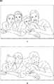
ここで、図2を参照して、画像処理装置11による画像処理の概略について説明する。図2Aには、カメラ12により撮像され、画像処理装置11に入力される入力画像が示されており、図2Bには、画像処理装置11により画像処理が施され、ディスプレイ13に表示される出力画像が示されている。 Here, the outline of the image processing by the
画像処理装置11は、入力画像に映されているユーザの顔を検出し、その顔から抽出される属性(特徴)に基づいて、大人の顔であるか子供の顔であるか、および、男性の顔であるか女性の顔であるかの判定を行う。そして、画像処理装置11は、判定結果に従ったアバタを生成し、ユーザの顔の位置に重ね合わされてアバタが表示されるように、入力画像にアバタを合成した出力画像を生成する。これにより、入力画像に含まれる大人の男性の顔が、大人の男性に対応するアバタに置き換えられた出力画像が表示され、入力画像に含まれる大人の女性の顔が、大人の女性に対応するアバタに置き換えられた出力画像が表示される。また、図2の例では、入力画像に含まれる子供の顔は、子供に対応するアバタとしての動物のキャラクタに置き換えられている。 The
また、画像処理装置11は、カメラ12により撮像される動画像に対してリアルタイムに画像処理を施すことができ、ユーザの表情が変化すると、その変化に合わせてアバタの表情を変化させることができる。 Further, the
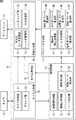
図1において、画像処理装置11は、カメラ入力部14、顔認識部15、モデル選択部16、パラメータ生成部17、および画像生成部18を備えて構成される。 In FIG. 1, the
カメラ入力部14は、カメラ制御部21およびデコード部22を備えて構成され、カメラ12により撮像された画像がカメラ入力部14に入力される。カメラ制御部21は、カメラ12からの画像に基づき、カメラ12に対して露出やホワイトバランスなどを調整する制御を行う。 The
また、カメラ12からカメラ入力部14に入力される画像は、いわゆるRAWデータ(即ち、撮像素子から出力された状態で画像処理が施されていないデータ)とされている。デコード部22は、そのRAWデータの画像を、RGB+Yデータ(赤(Red)、緑(Green)、青(Blue)の三つの原色と、輝度信号Yにより画像を表すデータ)の画像に変換し、顔認識部15に供給する。 The image input from the
顔認識部15は、顔認識制御部31、顔検出処理部32、パーツ検出部33、属性判別部34、および詳細パーツ検出部35を備えて構成され、カメラ入力部14のデコード部22から供給される画像に対して顔認識処理を施す。 The
顔認識制御部31は、顔認識部15の各部に対する制御を行う。例えば、顔認識制御部31は、属性判別部34からの出力が、新たに顔が検出されたフレームから所定数のフレーム(例えば、15フレーム)までの間、モデル選択部16に供給され、所定数のフレーム後、パラメータ生成部17に供給されるように制御を行う。 The face
顔検出処理部32には、カメラ入力部14から出力される画像が供給され、顔検出処理部32は、その画像から、ユーザの顔が映されている領域(以下、適宜、顔領域と称する)を検出する顔検出処理を行う。例えば、顔検出処理部32は、全体サーチと局所サーチとの2段階で顔検出処理を行う。顔検出処理部32は、全体サーチにおいて、画像の全体を対象とし、画像に表示されている顔ごとに顔領域を探索する処理を行い、局所サーチにおいて、全体サーチにより既に検出された顔領域を中心とした局所的な探索を行う。また、全体サーチでは、複数のユーザの顔(ターゲット)を検出することができ、局所サーチでは、全体サーチで検出された各顔をトラッキング(追跡)することができる。 An image output from the
そして、顔検出処理部32は、カメラ入力部14からの画像にユーザの顔が映っている場合、その顔の顔領域を特定する情報である顔探索結果情報(Face Detection Result)を出力する。例えば、顔検出処理部32は、全体サーチにより、それまでの画像に映っていなかった新規の顔が検出されると、その顔に対する顔探索結果情報の出力を開始する。そして、顔検出処理部32は、その顔が画像に映っている間、局所サーチにおいてトラッキングを行い、その顔に対する顔探索結果情報の出力を継続する。また、顔探索結果情報には、顔領域の基準点、横幅、縦長、および回転角度(faceX,faceY,faceW,faceH,faceRoll,faceYaw)が含まれる。 When the user's face is shown in the image from the
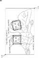
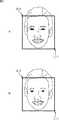
ここで、図3を参照して、顔探索結果情報について説明する。例えば、図3に示すように、顔領域の基準点(faceX,faceY)は、画像全体の左上の頂点を(0,0)とし、画像全体の右下の頂点を(1,1)として、正規化した値での顔領域の左上の頂点のXY座標で表される。また、顔領域の横幅および縦長(faceW,faceH)は、顔の両目を結ぶ線に平行な顔領域の辺を横方向とし、横方向に直交する辺を縦方向として、顔領域の基準点と同様に正規化した値で表される。また、顔領域の回転角度(faceRoll,faceYaw)は、後述の図6に示すように、右手座標系で表される。 Here, the face search result information will be described with reference to FIG. For example, as shown in FIG. 3, the reference point (faceX, faceY) of the face area has the upper left vertex of the entire image as (0,0) and the lower right vertex of the entire image as (1,1). It is represented by the XY coordinates of the upper left vertex of the face area with the normalized value. Also, the width and length (faceW, faceH) of the face area are determined by taking the face area side parallel to the line connecting the eyes of the face as the horizontal direction and the side perpendicular to the horizontal direction as the vertical direction, Similarly, it is expressed as a normalized value. Further, the rotation angle (faceRoll, faceYaw) of the face area is represented in the right-handed coordinate system as shown in FIG.
パーツ検出部33(図1)は、顔検出処理部32により検出された顔領域内にある顔の右目、左目、鼻、および口を、ユーザの顔のパーツとしてそれぞれ検出し、各パーツの中心点を示す座標を示す情報であるパーツ情報を出力する。パーツ情報では、右目、左目、鼻、および口の中心点を示す座標が、顔領域の左上の頂点である基準点(faceX,faceY)を(0,0)とし、顔領域の右下の頂点を(1,1)として、正規化した値で表される。 The part detection unit 33 (FIG. 1) detects the right eye, left eye, nose, and mouth of the face in the face area detected by the face detection processing unit 32 as user face parts, and the center of each part. The part information which is the information indicating the coordinates indicating the point is output. In the part information, the coordinates indicating the center point of the right eye, left eye, nose, and mouth are the upper left vertex of the face area (faceX, faceY) is (0,0), and the lower right vertex of the face area Is expressed as a normalized value with (1,1).
また、パーツ検出部33は、検出したパーツ同士の配置関係に基づいて、顔の位置および姿勢を求め、顔の位置および姿勢を示す情報である顔ポジション情報(Face Position)を出力する。顔ポジション情報には、顔領域の頂点となる4点の座標および顔の姿勢(regionX[0]〜[3],regionY[0]〜[3],PoseRoll,PosePitch,PoseYaw)が含まれる。 Further, the part detection unit 33 obtains the face position and posture based on the arrangement relationship between the detected parts, and outputs face position information (Face Position) that is information indicating the face position and posture. The face position information includes the coordinates of the four points that are the vertices of the face area and the posture of the face (regionX [0] to [3], regionY [0] to [3], PoseRoll, PosePitch, PoseYaw).
ここで、図4を参照して、顔ポジション情報について説明する。例えば、図4に示すように、顔領域の頂点となる4点の座標(regionX[0]〜[3],regionY[0]〜[3])は、画像全体の左上の頂点を(0,0)とし、画像全体の右下の頂点を(1,1)として、正規化した値で表される。また、顔領域の姿勢(PoseRoll,PosePitch,PoseYaw)は、後述の図6に示すように、左手座標系で表される。 Here, the face position information will be described with reference to FIG. For example, as shown in FIG. 4, the coordinates of the four points (regionX [0] to [3], regionY [0] to [3]) serving as the vertices of the face region are represented by (0, 0), and the lower right vertex of the entire image is (1,1) and is represented by a normalized value. Further, the posture of the face area (PoseRoll, PosePitch, PoseYaw) is represented in the left-handed coordinate system as shown in FIG.
属性判別部34(図1)は、パーツ検出部33から出力されるパーツ情報に基づいて、画像に表示されている顔の属性を判別し、その顔の属性を示す情報である属性情報を出力する。属性情報には、笑顔スコア(smile)、右目の開度スコア(R eye Open)、左目の開度スコア(L eye Open)、男性スコア(Male)、大人スコア(Adult)、赤ちゃんスコア(Baby)、老人スコア(Elder)、メガネスコア(Glasses)などが含まれる。 The attribute discrimination unit 34 (FIG. 1) discriminates the attribute of the face displayed in the image based on the part information output from the part detection unit 33, and outputs attribute information that is information indicating the attribute of the face. To do. The attribute information includes smile score (smile), right eye opening score (R eye Open), left eye opening score (L eye Open), male score (Male), adult score (Adult), and baby score (Baby). , Elder score, Glasses score, etc.
例えば、笑顔スコアは、ユーザの顔の笑顔の度合い、右目の開度スコアは、ユーザの右目が開いている度合い、左目の開度スコアは、ユーザの左目が開いている度合い、男性スコアは、ユーザの顔が男性である度合いを数値化したものである。また、大人スコアは、ユーザの顔が大人である度合い、赤ちゃんスコアは、ユーザの顔が赤ちゃんである度合い、老人スコアは、ユーザの顔が老人である度合い、メガネスコアは、ユーザの顔にメガネが掛けられている度合いを数値化したものである。例えば、属性判別部34には、ユーザの顔のパーツの位置から各スコアを判別するためのデータが学習などにより予め求められて記憶されており、属性判別部34は、そのデータを参照して、ユーザの顔から各スコアを求めることができる。 For example, the smile score is the degree of smile of the user's face, the opening score of the right eye is the degree of opening of the user's right eye, the opening score of the left eye is the degree of opening of the user's left eye, and the male score is The degree to which the user's face is male is quantified. The adult score is the degree to which the user's face is an adult, the baby score is the degree to which the user's face is a baby, the elderly score is the degree to which the user's face is an elderly person, and the glasses score is the glasses on the user's face. This is a numerical value of the degree to which is applied. For example, in the
詳細パーツ検出部35は、画像に表示される顔のパーツ(輪郭、眉、目、鼻、口など)の位置や形状など、各パーツを詳細に特定するためのポイントを検出し、それらのポイントを示す情報であるパーツ結果情報(Parts Result)を出力する。 The detailed
ここで、図5を参照して、パーツ結果情報について説明する。詳細パーツ検出部35は、顔全体から各パーツのポイントを検出する通常処理と、口の輪郭のポイントを検出する軽量処理とを行うことができる。 Here, the part result information will be described with reference to FIG. The detailed
即ち、通常処理では、図5Aに示すように、顔の輪郭、眉の形状、目の輪郭、鼻の形状、口の輪郭を特定する55箇所のポイントが検出される。また、軽量処理では、図5Bに示すように、口の輪郭を特定する14箇所のポイントが検出される。各ポイントのXY座標は、顔領域の左上の頂点の座標を(0,0)とし、顔領域の右下の頂点の座標を(1,1)として正規化した値で表される。パーツ結果情報では、各ポイントを識別するパーツID(partsID[0]〜[55])と、それぞれ対応するポイントのXY座標(partsX partsY)とが対応付けられている。 That is, in the normal process, as shown in FIG. 5A, 55 points that specify the contour of the face, the shape of the eyebrows, the contour of the eyes, the shape of the nose, and the contour of the mouth are detected. Further, in the lightweight processing, as shown in FIG. 5B, 14 points that specify the outline of the mouth are detected. The XY coordinates of each point are represented by normalized values with the coordinates of the upper left vertex of the face area as (0,0) and the coordinates of the lower right vertex of the face area as (1,1). In the part result information, a part ID (partsID [0] to [55]) for identifying each point is associated with an XY coordinate (partsX partsY) of the corresponding point.
また、例えば、ユーザの顔が傾くことにより、画像全体に対する顔のパーツの各ポイントの位置が回転(移動)したとしても、各ポイントのXY座標は顔領域で正規化された値で表されるので、顔領域の左上の頂点(原点)に対する各ポイントの位置は維持されたままである。このように、顔領域の傾きに応じて各ポイントの座標軸が回転するので、画像全体に対する各ポイントの位置を求める際には、顔領域の傾きに対して逆方向に傾かせる補正を行う必要がある。 Further, for example, even if the position of each point of the face part relative to the entire image is rotated (moved) due to the tilt of the user's face, the XY coordinates of each point are represented by values normalized in the face area. Therefore, the position of each point with respect to the upper left vertex (origin) of the face area remains maintained. As described above, since the coordinate axis of each point rotates in accordance with the inclination of the face area, when obtaining the position of each point with respect to the entire image, it is necessary to perform correction to incline in the opposite direction to the inclination of the face area. is there.
モデル選択部16(図1)には、顔認識制御部31の制御に従って、属性判別部34が出力する属性情報のうちの、男性スコアおよび大人スコアが供給される。顔認識制御部31は、例えば、顔検出処理部32により新たに顔が検出されたフレームから所定数のフレーム(例えば、15フレーム)までの間、属性判別部34から出力される男性スコアおよび大人スコアが、モデル選択部16に供給されるように制御を行う。 The model selection unit 16 (FIG. 1) is supplied with a male score and an adult score among the attribute information output by the
モデル選択部16は、属性判別部34から供給される男性スコアおよび大人スコアに基づいて、画像に映されているユーザの顔が、男性、女性、および子供のいずれであるかを判定する。そして、モデル選択部16は、画像生成部18がアバタの画像を生成する際に使用する三次元データとして、男性のモデル、女性のモデル、および子供のモデルのいずれかを選択し、その選択結果を示す情報であるモデル情報を画像生成部18に供給する。モデル選択部16における処理については、図15のフローチャートを参照して後述する。 The
パラメータ生成部17は、顔向き補正処理部41、フィルタ処理部42、顔向きパラメータ算出部43、顔位置パラメータ算出部44、目閉率パラメータ算出部45、口開率パラメータ算出部46、および笑顔パラメータ算出部47を備えて構成される。パラメータ生成部17では、画像生成部18がアバタを生成する際の制御データとなる各種のパラメータが生成される。 The
顔向き補正処理部41には、顔検出処理部32から出力される顔探索結果情報に含まれる顔領域の回転角度(faceRoll,faceYaw)と、パーツ検出部33から出力される顔ポジション情報に含まれる顔領域の姿勢(PoseRoll,PosePitch,PoseYaw)が供給される。 The face orientation
ここで、図6に示すように、顔探索結果情報に含まれる顔領域の回転角度の検出範囲、および顔ポジション情報に含まれる顔領域の姿勢の検出範囲が設定され、顔探索結果情報は図に示すような右手座標系で表され、顔ポジション情報は図に示すような左手座標系で表される。例えば、顔探索結果情報では、顔検出処理部32による顔のロール方向(Roll)に対する検出範囲は約±20度とされており、ピッチ方向(Pitch)の検出は行われず、ヨー方向(Yaw)に対する検出範囲は約±35度とされている。また、顔ポジション情報では、詳細パーツ検出部35による顔のロール方向(Roll)に対する検出範囲は約±35度とされており、ピッチ方向(Pitch)に対する検出範囲は約±20度とされており、ヨー方向(Yaw)に対する検出範囲は約±40度とされている。 Here, as shown in FIG. 6, the detection range of the rotation angle of the face area included in the face search result information and the detection range of the posture of the face area included in the face position information are set. The face position information is represented by a left-hand coordinate system as shown in the figure. For example, in the face search result information, the detection range for the face roll direction (Roll) by the face detection processing unit 32 is about ± 20 degrees, the pitch direction (Pitch) is not detected, and the yaw direction (Yaw) is detected. The detection range is about ± 35 degrees. Further, in the face position information, the detection range for the face roll direction (Roll) by the
ところで、画像生成部18が生成するアバタの顔角度を制御するためには、例えば、顔領域の姿勢を用いるだけでも十分であると思われるが、顔領域の姿勢の検出範囲の境界近傍においては、検出結果の値が不定期に変動する(震える)ようなノイズが発生することがある。このように、検出結果の値にノイズが発生すると、ユーザの顔が動いていないにもかかわらず、アバタがブルブルと震えることになる。 By the way, in order to control the face angle of the avatar generated by the
そこで、顔向き補正処理部41は、ユーザの顔の向きが、顔領域の姿勢の検出範囲の境界近傍である場合には、顔領域の姿勢の時間変動と、顔領域の回転角度の時間変動に基づいて、出力する顔向きを補正する処理を行う。 Therefore, when the user's face orientation is in the vicinity of the boundary of the face area posture detection range, the face direction
具体的には、検出範囲の境界近傍では、顔領域の回転角度は時間変動が発生し難い(安定している)のに対し、顔領域の姿勢の時間変動はノイズ成分により急激な変化を示す。従って、顔領域の回転角度が安定しているのに対し、顔領域の姿勢の時間変動が急激に変化しているとき、顔向き補正処理部41は、1フレーム前の顔領域の姿勢の検出結果を出力することで、ノイズ成分の出力を抑制することができる。そして、顔向き補正処理部41は、このような補正を行ったユーザの顔角度を出力する。 Specifically, in the vicinity of the boundary of the detection range, the rotation angle of the face region hardly changes (stable) with time, whereas the time variation of the posture of the face region shows a rapid change due to noise components. . Therefore, when the face area rotation angle is stable, but the temporal variation of the face area posture changes rapidly, the face orientation
フィルタ処理部42(図1)は、パラメータ生成部17の各パラメータ算出部(即ち、顔向きパラメータ算出部43、顔位置パラメータ算出部44、目閉率パラメータ算出部45、口開率パラメータ算出部46、および笑顔パラメータ算出部47)において算出されるパラメータに対し、それぞれのパラメータを安定化させるためのフィルタ処理を行う。 The filter processing unit 42 (FIG. 1) is a parameter calculation unit of the parameter generation unit 17 (that is, a face orientation
図7を参照して、フィルタ処理部42におけるフィルタ処理について説明する。 With reference to FIG. 7, the filter process in the filter process part 42 is demonstrated.
フィルタ処理部42は、図7Aに示すようなブロック図で表されるように構成されている。即ち、フィルタ処理部42は、各パラメータ算出部から出力されるパラメータxtを入力とし、画像生成部18においてアバタを生成する際の制御データとなるパラメータytを出力として、次の式(1)を演算する。The filter processing unit 42 is configured as shown in a block diagram as shown in FIG. 7A. That is, the filter processing unit 42 inputs the parameter xt output from each parameter calculator, as output parameters yt as the control data in generating an avatar in the

但し、式(1)において、αは、パラメータxtとパラメータyt-1とを足し込む際の足し込み比率であり、パラメータyt-1は、フィルタ処理部42から直前に出力されたパラメータである。However, in Expression (1), α is an addition ratio when adding the parameter xt and the parameter yt−1 , and the parameter yt−1 is the parameter output immediately before from the filter processing unit 42. It is.
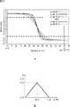
足し込み比率αは、図7Bに示すように、最大値maxと、2つの閾値thresAおよびthresBにより表される関数に従って、現在の入力値と1つ前の入力値との差分の絶対値である変数diff(=|curr−prev|)から算出される。即ち、足し込み比率αを求める関数は、変数diffが0から閾値thresAまでの間で一定の傾きで増加して閾値thresAで最大値maxとなり、閾値thresAから閾値thresBまでの間で最大値maxとなり、閾値thresB以降では、0から閾値thresAまでの傾きに対して逆の傾きで減少するような台形で表される。なお、閾値thresAと閾値thresBとが同一の値の場合、足し込み比率αを求める関数は、後述するように山形で現される。 The addition ratio α is the absolute value of the difference between the current input value and the previous input value according to the function represented by the maximum value max and the two threshold values thresA and thresB, as shown in FIG. 7B. It is calculated from the variable diff (= | curr−prev |). In other words, the function for calculating the addition ratio α is such that the variable diff increases with a constant slope from 0 to the threshold value thresA, reaches the maximum value max at the threshold value thresA, and reaches the maximum value max between the threshold value thresA and the threshold value thresB. After the threshold value thresB, it is represented by a trapezoid that decreases with an inclination opposite to the inclination from 0 to the threshold value thresA. When the threshold value thresA and the threshold value thresB are the same value, the function for obtaining the addition ratio α is expressed in a mountain shape as described later.
フィルタ処理部42には、最大値max、閾値thresA、および閾値thresBが設定されており、フィルタ処理部42は、変数diffから求められた足し込み比率αを用いて、上述の式(1)に従い、各パラメータ算出部からのパラメータを入力としてフィルタ処理を行う。そして、フィルタ処理部42は、フィルタ処理を施したパラメータを画像生成部18に供給する。 The filter processing unit 42 is set with a maximum value max, a threshold value thresA, and a threshold value thresB. The filter processing unit 42 uses the addition ratio α obtained from the variable diff according to the above equation (1). The filter processing is performed with the parameters from each parameter calculation unit as input. Then, the filter processing unit 42 supplies the parameter subjected to the filter processing to the
顔向きパラメータ算出部43(図1)は、顔向き補正処理部41により補正されたユーザの顔角度から、画像生成部18が生成するアバタの顔角度を制御するパラメータを算出する。 The face orientation parameter calculation unit 43 (FIG. 1) calculates parameters for controlling the avatar face angle generated by the
例えば、顔向き補正処理部41では、右手座標系で処理が行われるのに対し、画像生成部18では、左手座標系で処理が行われる。右手座標系と左手座標系とでは、図8Aに示すように、ロール方向(Roll)およびヨー方向(Yaw)との向きが逆であるので、顔向きパラメータ算出部43は、顔向き補正処理部41により補正されたユーザの顔角度の、ロール方向(Roll)およびヨー方向(Yaw)の符号を反転させる処理を行う。 For example, the face orientation
即ち、顔向きパラメータ算出部43は、図8Bに示すような関数に従って、入力されるユーザの顔角度をxとし、出力するアバタの顔角度をyとして、y=x−pを演算する。ここで、pは、顔向きの初期値をオフセットするための値であり、標準状態においてデフォルト値として0が設定(def=0.0)されている。 That is, the face orientation
そして、顔向きパラメータ算出部43から出力されるアバタの顔角度のパラメータは、フィルタ処理部42に供給され、上述の図7Aに示したようなフィルタ処理が施される。このとき、フィルタ処理部42のフィルタ処理で使用される足し込み比率αは、図8Cに示すように、最大値max=1.0、閾値thresA=0.1π、閾値thresB=0.2πで表される関数に従って求められる。 Then, the parameter of the avatar face angle output from the face orientation
顔位置パラメータ算出部44(図1)は、顔検出処理部32から出力される顔探索結果情報に含まれる顔領域の基準点、横幅、および縦長(faceX,faceY,faceW,faceH)から、画像生成部18が生成するアバタの顔位置を制御するパラメータを算出する。 The face position parameter calculation unit 44 (FIG. 1) calculates an image from the reference point, width, and portrait (faceX, faceY, faceW, faceH) of the face area included in the face search result information output from the face detection processing unit 32. A parameter for controlling the face position of the avatar generated by the
上述の図3に示したように顔検出処理部32が出力する顔探索結果情報では、顔領域の左上の頂点が基準点とされているのに対し、画像生成部18では、図9Aに示すように、顔領域の中心が基準点(図9Aで×印で示される点)とされる。また、顔認識制御部31では、画像全体の左上の頂点を原点(0,0)とした座標系(図3)で処理を行うのに対し、画像生成部18では、図9Aに示すように、画像全体の中心を原点(0,0)とした座標系で処理を行う。 In the face search result information output by the face detection processing unit 32 as shown in FIG. 3 described above, the upper left vertex of the face area is set as a reference point, whereas the
従って、顔位置パラメータ算出部44は、図9Bに示すような関数、即ち、次の式(2)を演算することにより、画像全体の中心を原点とした座標系における顔領域の中心点の座標を、顔位置のパラメータとして算出する。Accordingly, the face position
但し、式(2)において、xinおよびyinは、顔位置パラメータ算出部44に入力される顔領域の基準点、即ち、顔検出処理部32から出力される顔探索結果情報に含まれる顔領域の基準点のXY座標(faceX,faceY)である。また、winおよびhinは、顔位置パラメータ算出部44に入力される顔領域の横幅および縦長(faceW,faceH)である。また、xoutおよびyoutは、顔位置パラメータ算出部44から出力される顔位置のパラメータ(即ち、図9Aで×印で示される点のXY座標)である。ここで、xin,yin,win,hinは、0.0〜0.1の値域をとる画像全体の左上の頂点を原点(0,0)とした正規化座標系での値であり、xout,youtは、-0.1〜0.1の値域をとる画像全体の中心を原点(0,0)とした正規化座標系での値である。However, in Expression (2), xin and yin are the reference points of the face area input to the face position
そして、顔位置パラメータ算出部44から出力される顔位置のパラメータは、フィルタ処理部42に供給され、上述の図7Aに示したようなフィルタ処理が施される。このとき、フィルタ処理部42のフィルタ処理で使用される足し込み比率αは、図9Cに示すように、最大値max=0.8、閾値thresA=閾値thresB=0.8で表される関数に従って求められる。ここで、閾値thresAと閾値thresBとが同一の値である場合、足し込み比率αを求める関数は山型となり、台型の関数より安定化傾向が強められる。 Then, the face position parameters output from the face position
目閉率パラメータ算出部45(図1)は、属性判別部34により判別されたユーザの右目および左目の開度スコアから、画像生成部18が生成するアバタの右目および左目の閉鎖率を制御するパラメータを算出する。 The closing rate parameter calculation unit 45 (FIG. 1) controls the closing rate of the right eye and left eye of the avatar generated by the
例えば、目閉率パラメータ算出部45は、シグモイド関数を利用した次の式(3)を演算することにより、ユーザの右目および左目の開度スコアから、アバタの右目および左目の閉鎖率のパラメータをそれぞれ算出する。 For example, the closing rate
但し、式(3)において、yは閉鎖率であり、xは開度スコアであり、ofsは開度スコアの初期値をオフセットするための値であり、gradは、シグモイド関数の緩やかさを設定する設定値である。また、シグモイド関数により算出される値は、0.0〜1.0の範囲であり、gainは、その値の範囲を、中央値(0.5)を中心として増幅させるための増幅率である。 However, in equation (3), y is the closing rate, x is the opening score, ofs is a value for offsetting the initial value of the opening score, and grad sets the sigmoid function looseness This is the setting value. The value calculated by the sigmoid function is in the range of 0.0 to 1.0, and gain is an amplification factor for amplifying the range of the value around the median value (0.5).
図10Aに、複数の設定値grad(grad=0.2〜0.6)を用いてシグモイド関数を演算し、増幅率gainを1.4として求められる閉鎖率yと開度スコアxとの関係を示す。ここで、pは、ユーザの右目および左目の開度スコアの最大値として設定される値であり、標準状態における開度スコアの最大値のデフォルト値として6.75が設定(def=6.75)されている。また、標準状態におけるgradのデフォルト値として0.4が設定(def=0.4)されている。また、閉鎖率のパラメータには、最大値と最小値を設定することができ、図10Aでは、最大値が1.0に設定され、最小値が0.0に設定されている。 FIG. 10A shows a relationship between the closing rate y and the opening degree score x obtained by calculating a sigmoid function using a plurality of set values grad (grad = 0.2 to 0.6) and setting the gain gain to 1.4. Here, p is a value set as the maximum value of the opening score of the right eye and the left eye of the user, and 6.75 is set as a default value of the maximum value of the opening score in the standard state (def = 6.75). . In addition, 0.4 is set as the default value of grad in the standard state (def = 0.4). In addition, a maximum value and a minimum value can be set for the parameter of the closing rate. In FIG. 10A, the maximum value is set to 1.0 and the minimum value is set to 0.0.
このように、シグモイド関数を利用して、属性判別部34により判別されたユーザの右目および左目の開度スコアを、画像生成部18が生成するアバタの右目および左目の閉鎖率のパラメータに変換することで、例えば、目を完全に開いた状態での目の大きさの個人差を縮小させることや、顔の向きが目の開閉度に与える影響を抑制することができる。例えば、目の細い人では、開度スコアが低下する傾向や、顔が俯いているときには、開度スコアが低下する傾向などがあるが、閉鎖率のパラメータを、シグモイド関数を利用して求めることで、そのような傾向を抑制することができる。 In this way, using the sigmoid function, the opening scores of the user's right eye and left eye determined by the
さらに、シグモイド関数を利用することで、開いた状態の目と閉じた状態の目(ウィンクした目)とを表現するだけでなく、細めた状態の目(半目)をより自然に表現することができる。また、目を閉じ始める時点、または目を開き始める時点において、まぶたの動きが緩やかになるように、目の開閉を表現することができる。なお、シグモイド関数に代えて、最大値と最小値との間で線形に閉鎖率のパラメータが変化するような関数を利用しても、細めた状態の目を表現することができるが、シグモイド関数を利用することで、より人間の動作に近い目の開閉を表現することができる。 Furthermore, by using the sigmoid function, it is possible to express not only open eyes and closed eyes (winned eyes) but also more naturally expressing narrow eyes (half eyes). it can. In addition, the opening and closing of the eyes can be expressed so that the movement of the eyelids becomes gentle at the time when the eyes start to close or the eyes start to open. Note that instead of the sigmoid function, a narrowed eye can be expressed by using a function in which the parameter of the closing rate linearly changes between the maximum value and the minimum value. By using, it is possible to express the opening and closing of eyes closer to human movement.
そして、目閉率パラメータ算出部45から出力される右目および左目の閉鎖率のパラメータは、フィルタ処理部42に供給され、上述の図7Aに示したようなフィルタ処理が施される。このとき、フィルタ処理部42のフィルタ処理で使用される足し込み比率αは、図10Bに示すように、最大値max=0.8、閾値thresA=閾値thresB=0.8で表される関数に従って求められる。 The right eye and left eye closing rate parameters output from the closing rate
口開率パラメータ算出部46(図1)は、詳細パーツ検出部35により検出されたユーザの口の輪郭を特定する14箇所のポイントから、画像生成部18が生成するアバタの口の開率を制御するパラメータを算出する。 The mouth opening rate parameter calculation unit 46 (FIG. 1) calculates the opening rate of the avatar mouth generated by the
ここで、口開率パラメータ算出部46は、パラメータを算出する前に、ユーザの口の輪郭を特定する各ポイントに基づいて、口の輪郭の検出結果が正しいものであるか否かを判定する2つの評価を行う。 Here, before calculating the parameters, the mouth opening rate
まず、第1の評価には、所定のポイントどうしの垂直方向の距離が用いられる。例えば、口開率パラメータ算出部46は、図11Aの左側に示すように、ユーザの口の輪郭を特定する14箇所のポイントのうちの、右端のポイントを除いた右側の4つのポイントの、隣り合うポイントどうしの垂直方向の距離(R1,R2,R3)を求める。同様に、口開率パラメータ算出部46は、左端のポイントを除いた左側の4つのポイントの、隣り合うポイントどうしの垂直方向の距離(L1,L2,L3)と、中央のポイントの、隣り合うポイントどうしの垂直方向の距離(C1,C2,C3)とを求める。そして、口開率パラメータ算出部46は、このようにして求めた全ての垂直方向の距離が正数である場合、口の輪郭の検出結果が正しいものであると判定する。 First, a vertical distance between predetermined points is used for the first evaluation. For example, as shown on the left side of FIG. 11A, the mouth opening ratio
また、第2の評価には、所定のポイントを対角とした矩形領域の形状が用いられる。例えば、口開率パラメータ算出部46は、図11Aの右側に示すように、ユーザの口の輪郭を特定する14箇所のポイントのうちの、上唇の下側の3つのポイントの、隣り合うポイントを対角とした矩形領域(T1、T2)の形状を求める。同様に、口開率パラメータ算出部46は、ユーザの口の輪郭を特定する14箇所のポイントのうちの、下唇の上側の3つのポイントの、隣り合うポイントを対角とした矩形領域(T3、T4)の形状を求める。そして、口開率パラメータ算出部46は、このようにして求めた全ての矩形領域が横長である場合、口の輪郭の検出結果が正しいものであると判定する。 In the second evaluation, the shape of a rectangular area with a predetermined point as a diagonal is used. For example, as shown on the right side of FIG. 11A, the mouth opening rate
口開率パラメータ算出部46は、第1および第2の評価において口の輪郭の検出結果が正しいものであると判定した場合、詳細パーツ検出部35により検出されたユーザの口の輪郭を特定する14箇所のポイントから、画像生成部18が生成するアバタの口の開率のパラメータを算出する。即ち、口の輪郭の検出結果が正しいものである場合に、ユーザの口の開き具合が、アバタの口に反映される。 When the mouth opening ratio
口開率パラメータ算出部46は、上唇の下側の中央のポイントと、下唇の上側の中央のポイントとの垂直方向の距離(即ち、図11Aの距離C2:height)を入力とし、図11Bに示すような関数(y=(1/p)×x−0.1)を演算して、口開率のパラメータを算出する。この式において、xは、入力値である垂直方向の距離(height)であり、yは、出力値である口開率のパラメータ(Open Ratio)である。また、pは、入力値である垂直方向の距離(height)の最大値を設定するための値であり、標準状態におけるデフォルト値として0.09が設定(def=0.09)されており、最大値は0.19とされている。このように、口開率を示すパラメータは、ユーザの口が最も開いた状態を標準状態として設定し、距離(height)に線形に対応付けられる。 The mouth opening ratio
なお、口の中心位置と鼻の中心位置との距離から、口開率を示すパラメータを算出するための距離を求めてもよい。この場合、例えば、口の中心位置と鼻の中心位置との距離を0.4倍した値が、上述の入力値(height)として用いられる。 Note that a distance for calculating a parameter indicating the mouth opening rate may be obtained from the distance between the center position of the mouth and the center position of the nose. In this case, for example, a value obtained by multiplying the distance between the center position of the mouth and the center position of the nose by 0.4 is used as the above-described input value (height).
そして、口開率パラメータ算出部46から出力される口開率を示すパラメータは、フィルタ処理部42に供給され、上述の図7Aに示したようなフィルタ処理が施される。このとき、フィルタ処理部42のフィルタ処理で使用される足し込み比率αは、図11Cに
すように、最大値max=0.8、閾値thresA=閾値thresB=0.8で表される関数に従って求められる。Then, the parameter indicating the mouth opening rate output from the mouth opening rate
笑顔パラメータ算出部47(図1)は、属性判別部34から出力される属性情報に含まれる笑顔スコアから、画像生成部18が生成するアバタの笑顔率を制御するパラメータを算出する。 The smile parameter calculation unit 47 (FIG. 1) calculates a parameter for controlling the avatar smile rate generated by the
属性判別部34により検出される笑顔スコアは、例えば、0から70までの数値で表されており、笑顔パラメータ算出部47は、図12Aに示すような関数(y=(1/50)×x−0.4)を演算して、笑顔率を示すパラメータを求める。この式において、xは、入力値である笑顔(Smile)スコアであり、yは、出力値である笑顔率を示すパラメータ(Smile Ratio)である。 The smile score detected by the
そして、笑顔パラメータ算出部47から出力される笑顔率のパラメータは、フィルタ処理部42に供給され、上述の図7Aに示したようなフィルタ処理が施される。このとき、フィルタ処理部42のフィルタ処理で使用される足し込み比率αは、図12Bに示すように、最大値max=0.8、閾値thresA=閾値thresB=0.8で表される関数に従って求められる。 The smile rate parameter output from the smile
このように、パラメータ生成部17の各パラメータ生成部において生成されたパラメータは、画像生成部18(図1)に供給され、画像生成部18は、それらのパラメータに従ってアバタを生成する。 Thus, the parameters generated in each parameter generation unit of the
画像生成部18は、三次元データ管理部51、シェーダ管理部52、レンダリング部53、および合成処理部54を備えて構成される。 The
三次元データ管理部51は、アバタの三次元データの管理、例えば、男性、女性、および子供のアバタの三次元データを記憶しているデータベース(図示せず)の管理を行う。また、三次元データ管理部51には、モデル選択部16からモデル情報(画像に表示される顔が、男性、女性、および子供のいずれであるかの判定結果を示す情報)が供給される。そして、三次元データ管理部51は、そのモデル情報に応じたアバタの三次元データを、データベースから読み出してレンダリング部53に供給する。 The three-dimensional
また、三次元データ管理部51は、三次元モデルの座標を出力画像(二次元)に変換するためのジオメトリ処理や、三次元モデルの表面に質感を与えるためのテクスチャを貼り付けるテクスチャ処理などを行うための各種のデータを管理し、それらのデータをレンダリング部53に供給する。 In addition, the 3D
シェーダ管理部52は、レンダリング部53において三次元データをレンダリングする際に、所定の光源(照明)により三次元モデルに陰影をつけるための演算を行うシェーディング処理を管理し、シェーディング処理による演算結果をレンダリング部53に供給する。 When the
レンダリング部53は、パラメータ生成部17の各パラメータ生成部から出力された表情パラメータ(例えば、アバタの右目および左目の目閉率を示すパラメータ、アバタの笑顔率を示すパラメータ、アバタの口開率を示すパラメータ)に従って、三次元データ管理部51から供給された三次元データを変形(モーフィング)させて、レンダリングを行う。 The
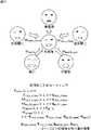
ここで、三次元データ管理部51は、1つのモデルについて、複数の基本表情の三次元データをレンダリング部53に供給している。例えば、三次元データ管理部51は、子供、男性、および女性のモデルごとに、図13に示すような無表情の三次元データ、右目閉じの三次元データ、左目閉じの三次元データ、笑いの三次元データ、口開きの三次元データをレンダリング部53に供給する。 Here, the 3D
そして、レンダリング部53は、これらの基本表情の三次元データの各頂点を、それぞれ対応するパラメータで重み付け加算して、レンダリングする三次元データの各頂点を求める。即ち、レンダリングする三次元データの所定の頂点Psynth(x,y,z)は、右目閉じの三次元データの所定の頂点をPreye_close(x,y,z)とし、アバタの右目の目閉率を示すパラメータをWreye_closeとし、左目閉じの三次元データの所定の頂点をPleye_close(x,y,z)とし、アバタの左目の目閉率を示すパラメータをWleye_closeとし、口開きの三次元データの所定の頂点をPmouth_open(x,y,z)とし、アバタの口開率を示すパラメータをWmouth_openとし、笑いの三次元データの所定の頂点をPsmile(x,y,z)とし、アバタの笑顔率を示すパラメータをWsmileとし、無表情の三次元データの所定の頂点をPnormal(x,y,z)とすると、Psynth(x,y,z)=Preye_close(x,y,z)×Wreye_close+Pleye_close(x,y,z)×Wleye_close+Pmouth_open(x,y,z)×Wmouth_open+Psmile(x,y,z)×Wsmile+Pnormal(x,y,z)×(1−Wreye_close−Wleye_close−Wsmile−Wmouth_open)で求められる。The
そして、レンダリング部53は、各基本表情の三次元データを、それぞれ対応するパラメータで重み付け加算して求めたモーフィング後の三次元データを用いてレンダリング処理を行い、アバタの顔の画像を生成する。また、レンダリング部53は、顔向きパラメータ算出部43から出力されるアバタの顔角度のパラメータに従った向きのアバタの画像が生成されるように、モーフィング後の三次元データの向きを設定してレンダリング処理を行う。 The
合成処理部54には、レンダリング部53によりレンダリングされたアバタの顔の画像が供給されるとともに、そのアバタの顔位置を制御するパラメータが顔位置パラメータ算出部44から供給される。また、合成処理部54には、カメラ12により撮像された画像がカメラ入力部14から供給される。 The composition processing unit 54 is supplied with the image of the avatar's face rendered by the
合成処理部54は、カメラ12により撮像された画像(例えば、図2Aの入力画像)に映されているユーザの顔の位置に、アバタの顔位置を制御するパラメータに従って、レンダリング部53から供給されたアバタの顔が重ね合わされるように、ユーザの顔をアバタに置き換える合成処理を行う。そして、合成処理部54は、その合成処理を行った結果得られる画像(例えば、図2Bの出力画像)を、ディスプレイ13に供給して表示させる。 The compositing processing unit 54 is supplied from the
次に、図14は、図1の画像処理装置11により実行される画像処理を説明するフローチャートである。 Next, FIG. 14 is a flowchart illustrating image processing executed by the
例えば、画像処理装置11は、ユーザの操作に従って処理を開始し、ステップS11において、カメラ入力部14は、カメラ12から入力される画像を取得する。カメラ入力部14は、デコード部22によりカメラ12からの画像(RAWデータ)をデコードして、顔認識部15の顔検出処理部32に供給し、処理はステップS12に進む。 For example, the
ステップS12において、顔検出処理部32は、ステップS11でカメラ入力部14から供給された画像から、ユーザの顔が映っている顔領域を検出する顔検出処理を行う。そして、顔検出処理部32は、顔領域が検出されると顔探索結果情報を出力する。 In step S12, the face detection processing unit 32 performs a face detection process for detecting a face area in which the user's face is shown from the image supplied from the
ステップS12の処理後、処理はステップS13に進み、顔認識制御部31は、ステップS12の処理で顔検出処理部32により顔領域が検出されたか否か、即ち、顔検出処理部32から顔探索結果情報が出力されたか否かを判定する。 After the process of step S12, the process proceeds to step S13, and the face
ステップS13において、顔認識制御部31が、顔検出処理部32により顔領域が検出されていないと判定した場合、処理はステップS11に戻り、以下、同様の処理が繰り返される。一方、ステップS13において、顔認識制御部31が、顔検出処理部32により顔領域が検出されたと判定した場合、処理はステップS14に進む。 In step S13, when the face
ステップS14において、パーツ検出部33は、ステップS12で顔検出処理部32から出力された顔探索結果情報により示される顔領域から、顔のパーツを検出する処理を行う。そして、パーツ検出部33は、右目、左目、鼻、および口の各パーツの中心点を示す座標を示すパーツ情報と、それらのパーツから求められる顔の位置および姿勢を示す顔ポジション情報とを出力し、処理はステップS15に進む。 In step S14, the parts detection unit 33 performs a process of detecting facial parts from the face area indicated by the face search result information output from the face detection processing unit 32 in step S12. Then, the part detection unit 33 outputs part information indicating coordinates indicating the center point of each part of the right eye, left eye, nose, and mouth, and face position information indicating the position and posture of the face obtained from these parts. Then, the process proceeds to step S15.
ステップS15において、属性判別部34は、ステップS14でパーツ検出部33から出力されたパーツ情報に基づいて、顔領域内にあるユーザの顔の属性を判別し、その判別結果を示す属性情報を出力する。上述したように、属性情報には、男性スコアおよび大人スコアが含まれている。 In step S15, the
ステップS15の処理後、処理はステップS16に進み、顔認識制御部31は、現在処理の対象としている顔領域が、新規の顔領域であるか否かを判定する。例えば、画像処理装置11では、カメラ12から入力される画像の1フレームごとに処理が行われ、顔認識制御部31は、現在処理の対象となっている顔領域が初めて検出されたフレームから直前のステップS12で検出されたフレームまでのフレーム数が、15フレーム以下であれば、現在処理の対象としている顔領域が新規のターゲットであると判定し、15フレームより大であれば、現在処理の対象としている顔領域が新規のターゲットではないと判定する。 After the process of step S15, the process proceeds to step S16, and the face
ステップS16において、顔認識制御部31が、現在処理の対象としている顔領域が新規の顔領域であると判定した場合、処理はステップS17に進む。 If the face
ステップS17において、顔認識制御部31は、ステップS15で属性判別部34から出力される属性情報に含まれる男性スコアおよび大人スコアをモデル選択部16に供給し、処理はステップS18に進む。 In step S17, the face
ステップS18において、モデル選択部16は、ステップS17で顔認識制御部31から供給された男性スコアおよび大人スコアに基づいて、顔領域内にあるユーザの顔を置き換えるアバタの三次元データとして、男性のモデル、女性のモデル、および子供のモデルのいずれかを選択するモデル選択処理を行う。モデル選択処理については、図15を参照して後述する。ステップS17のモデル選択処理の処理後、処理はステップS11に戻り、次のフレームを処理の対象として、以下、同様の処理が繰り返される。 In step S18, the
一方、ステップS16において、顔認識制御部31が、現在処理の対象としている顔領域が新規の顔領域でないと判定した場合、処理はステップS19に進む。 On the other hand, if the face
ステップS19において、詳細パーツ検出部35は、顔領域内にあるユーザの顔のパーツを詳細に特定するためのポイント(図5参照)を検出し、パーツ結果情報を出力して、処理はステップS20に進む。 In step S19, the detailed
ステップS20において、顔向き補正処理部41は、顔領域内にあるユーザの顔の向きを補正する顔向き補正処理を行う。顔向き補正処理については、図16を参照して後述する。顔向き補正処理の処理後、処理はステップS21に進む。 In step S20, the face orientation
ステップS21において、パラメータ生成部17の各パラメータ算出部はパラメータを算出する。即ち、顔向きパラメータ算出部43は、ステップS20で顔向き補正処理部41から出力されるユーザの顔角度から、アバタの顔角度を示すパラメータを算出する。顔位置パラメータ算出部44は、ステップS12で顔認識制御部31が出力する顔探索結果情報から、アバタの顔位置を示すパラメータを算出する。 In step S21, each parameter calculation unit of the
また、目閉率パラメータ算出部45は、ステップS15で属性判別部34により判別されたユーザの右目および左目の開度スコアから、アバタの右目および左目の目閉率を示すパラメータを算出する。口開率パラメータ算出部46は、ステップS19で詳細パーツ検出部35により検出されたユーザの口の輪郭を特定する14箇所のポイントから、アバタの口開率を示すパラメータを算出する。笑顔パラメータ算出部47は、ステップS15で属性判別部34から出力される属性情報に含まれる笑顔スコアから、アバタの笑顔率を示すパラメータを算出する。 Further, the closing rate
ステップS22において、フィルタ処理部42は、顔向きパラメータ算出部43、顔位置パラメータ算出部44、目閉率パラメータ算出部45、口開率パラメータ算出部46、および笑顔パラメータ算出部47により算出される各パラメータに対し、図7を参照して説明したように、それぞれのパラメータを安定化させるためのフィルタ処理を施し、フィルタ処理が施されたパラメータを画像生成部18に供給する。 In step S <b> 22, the filter processing unit 42 is calculated by the face orientation
ステップS23において、画像生成部18は、ディスプレイ13に表示させる画像を生成する画像生成処理を行う。 In step S <b> 23, the
即ち、画像生成部18では、三次元データ管理部51が、ステップS18のモデル選択処理でモデル選択部16から出力されるモデル情報に従って、顔領域内のユーザの顔を置き換えるアバタについての5つの表情の三次元データをレンダリング部53に供給する。そして、レンダリング部53は、それらの5つの表情の三次元データを、ステップS22でフィルタ処理部42から供給される各パラメータに応じてモーフィングして、アバタの画像を生成する。その後、合成処理部54は、レンダリング部53によりレンダリングされたアバタの画像を、カメラ12により撮像された画像に映されているユーザの顔の位置に合成させ、ユーザの顔がアバタに置き換えられた画像を生成する。画像生成処理の処理後、処理はステップS24に進む。 That is, in the
ステップS24において、画像生成部18は、ステップS23で生成された画像をディスプレイ13に供給して表示させ、処理はステップS11に戻り、次のフレームを処理の対象として、以下、同様の処理が繰り返される。 In step S24, the
以上のように、画像処理装置11では、ユーザの属性に従ったアバタが自動的に表示されるので、ユーザがアバタを指定する手間を省くことができる。即ち、従来、ユーザの顔をアバタに置き換えて表示させるには、ユーザが、自身の属性に応じたアバタを指定しなければならなかった。これに対し、画像処理装置11では、そのような手間を省くことができ、ユーザの顔がカメラ12により撮像されるのとほぼ同時に、ユーザの属性に従ったアバタがディスプレイ13に表示されるようになる。これにより、ユーザがアバタとの一体感を感じることができ、例えば、画像処理装置11をゲームやチャットなどの仮想空間に適用したとき、その仮想空間により素直に感情移入しやすくなる。 As described above, since the avatar according to the user attribute is automatically displayed in the
また、各パラメータに対してフィルタ処理を施しているので、アバタの動きが滑らかになり、ユーザがアバタとの一体感をより強く感じることができる。例えば、画像に映されている顔を検出する顔検出処理においては、数ピクセルの誤差が許容されており、顔が動いていない(または、ゆっくり動いている)とき、その誤差によってアバタの位置が振動する(微小幅で高速に振れる)ことがある。このような場合にも、フィルタ処理を施すことで、アバタの振動を防止することができ、ユーザ(仮想空間の画像を見たり、ゲームを操作しているユーザ)が、そのような振動を見ることによって不快感を受けることを防止することができる。 In addition, since the filter processing is applied to each parameter, the avatar moves smoothly, and the user can feel a sense of unity with the avatar more strongly. For example, in the face detection process for detecting a face shown in an image, an error of several pixels is allowed. When the face is not moving (or moving slowly), the position of the avatar is determined by the error. It may vibrate (should swing at high speed with a minute width). Even in such a case, it is possible to prevent the vibration of the avatar by performing the filter process, and the user (the user who views the image of the virtual space or operates the game) sees such vibration. It is possible to prevent the user from feeling uncomfortable.
さらに、図7を参照して説明したように、足し込み比率αを、動的に、現在の入力値と1つ前の入力値との差分の絶対値である変数diffを用いて求めることで、顔が動いていない(または、ゆっくり動いている)ときと、顔が速く動いているときとの両方に適したフィルタ処理を行うことができる。即ち、顔が動いていないときには、足し込み比率αの値を小さくする(直前の出力値(パラメータyt-1)の重みを大きくして、入力値(パラメータxt)の重みを小さくする)ことで、顔の位置を安定化させることができる。一方、顔が速く動いているときには、足し込み比率αの値を大きくすることで、顔の移動に対する追従性を高くして、より正確な位置にアバタを表示することができる。なお、顔が速く動いているときには、顔の移動量に対して顔検出処理における誤差は相対的に小さくなるので、上述したようなアバタの振動が気になることはない。このようなフィルタ処理により、ユーザに対して、直感的な視覚効果を与えることができる。Furthermore, as described with reference to FIG. 7, the addition ratio α is dynamically obtained by using a variable diff that is an absolute value of a difference between the current input value and the previous input value. Filter processing suitable for both when the face is not moving (or moving slowly) and when the face is moving fast can be performed. That is, when the face is not moving, the value of the addition ratio α is decreased (the weight of the previous output value (parameter yt-1 ) is increased and the weight of the input value (parameter xt ) is decreased). Thus, the face position can be stabilized. On the other hand, when the face is moving fast, increasing the value of the addition ratio α increases the followability to the movement of the face and can display the avatar at a more accurate position. Note that when the face is moving fast, the error in the face detection process is relatively small with respect to the amount of movement of the face, so the avatar vibration as described above is not a concern. By such a filtering process, an intuitive visual effect can be given to the user.
また、パラメータ生成部17において生成された表情パラメータにより表情合成を行ってレンダリングするので、アバタの表情を従来よりも豊かなものにすることができる。このように、画像処理装置11により画像処理を施すことにより、バーチャルコミュニケーションにおける新しいユーザ体験を提供したり、仮想空間でのよりリッチなコミュニケーションを提供することができる。 In addition, since facial expression synthesis is performed using the facial expression parameters generated by the
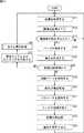
次に、図15は、図14のステップS18におけるモデル選択処理を説明するフローチャートである。 Next, FIG. 15 is a flowchart for explaining the model selection processing in step S18 of FIG.
ステップS31において、モデル選択部16は、モデル選択処理において使用される各種のカウント値を初期化する処理を行う。モデル選択処理では、処理を行ったフレーム数をカウントするフレーム数カウント値、子供であると判定された回数をカウントする子供カウント値、男性であると判定された回数をカウントする男性カウント値、女性であると判定された回数をカウントする女性カウント値が使用される。モデル選択部16は、これらのカウント値を初期化(例えば、0を入力)し、処理はステップS32に進む。 In step S31, the
ステップS32において、モデル選択部16は、図14のステップS17で顔認識制御部31から供給された大人スコアに基づいて、顔領域内にあるユーザの顔が子供であるか否かを判定する。例えば、モデル選択部16は、大人スコアが所定の閾値(例えば、大人スコアの最大値と最小値との中間の値)未満であれば、顔領域内にあるユーザの顔が子供であると判定し、大人スコアが所定の閾値以上であれば、顔領域内にあるユーザの顔が大人であると判定する。 In step S32, the
ステップS32において、モデル選択部16が、顔領域内にあるユーザの顔が子供であると判定した場合、処理はステップS33に進み、モデル選択部16は、子供カウント値を1つインクリメントする。 In step S32, when the
一方、ステップS32において、モデル選択部16が、顔領域内にあるユーザの顔が子供でないと判定した場合、処理はステップS34に進む。 On the other hand, when the
ステップS34において、モデル選択部16は、顔認識制御部31から供給された男性スコアに基づいて、顔領域内にあるユーザの顔が男性であるか否かを判定する。例えば、モデル選択部16は、男性スコアが所定の閾値(例えば、男性スコアの最大値と最小値との中間の値)以上であれば、顔領域内にあるユーザの顔が男性であると判定し、男性スコアが所定の閾値未満であれば、顔領域内にあるユーザの顔が男性でないと判定する。 In step S <b> 34, the
ステップS34において、モデル選択部16が、顔領域内にあるユーザの顔が男性であると判定した場合、処理はステップS35に進み、モデル選択部16は、男性カウント値を1つインクリメントする。一方、ステップS34において、モデル選択部16が、顔領域内にあるユーザの顔が男性でないと判定した場合、処理はステップS36に進み、モデル選択部16は、女性カウント値を1つインクリメントする。 In step S34, when the
ステップS33,S35、またはS36の処理後、処理はステップS37に進み、モデル選択部16は、フレーム数カウント値が、モデルの選択を行うフレームとして設定された所定数(例えば、15)以上であるか否かを判定する。 After the process of step S33, S35, or S36, the process proceeds to step S37, and the
ステップS37において、モデル選択部16が、フレーム数カウント値が、モデルの選択を行うフレームとして設定された所定数以上でない(所定数未満である)と判定した場合、処理はステップS38に進む。ステップS38において、モデル選択部16は、フレーム数カウント値を1つインクリメントし、処理はステップS32に戻り、次のフレームを処理の対象として、以下、同様の処理が繰り返される。 In step S37, if the
一方、ステップS37において、モデル選択部16が、フレーム数カウント値がモデルの選択を行うフレームとして設定された所定数以上であると判定した場合、処理はステップS39に進む。 On the other hand, when the
ステップS39において、モデル選択部16は、子供カウント値、男性カウント値、および女性カウント値を参照し、子供、男性、女性のうちの最も判定回数の多い(カウント値が高い)ものを、アバタの三次元データのモデルとして選択する。 In step S39, the
ステップS39の処理後、処理はステップS40に進み、モデル選択部16は、ステップS39での選択結果を示す情報であるモデル情報を画像生成部18に供給し、処理は終了する。 After the process in step S39, the process proceeds to step S40, and the
以上のように、モデル選択部16が、複数回の判定結果に基づいてモデルを選択することで、ユーザに一致するモデルを選択する確度を向上させることができる。例えば、属性判別部34は、照明の影響やユーザの表情などによって誤認識をすること(例えば、ユーザの顔が笑っているときに男性と女性とを逆に判別することなど)があり、不安定なスコアが出力されることがある。このようなときでも、モデル選択部16が複数回の判定結果を用いることで、属性判別部34における誤認識の影響を排除することができる。 As described above, the
次に、図16は、図14のステップS20における顔向き補正処理を説明するフローチャートである。 Next, FIG. 16 is a flowchart illustrating the face orientation correction process in step S20 of FIG.
ステップS51において、顔向き補正処理部41は、図14のステップS12において顔領域が検出されたときに顔検出処理部32から出力される顔探索結果情報に含まれる顔領域の回転角度(faceRoll,faceYaw)と、ステップS14においてパーツ検出部33から出力される顔ポジション情報に含まれる顔領域の姿勢(PoseRoll,PoseYaw)とを取得する。 In step S51, the face orientation
ステップS51の処理後、処理はステップS52に進み、顔向き補正処理部41は、顔領域内にあるユーザの顔の向きが、検出範囲の境界近傍か否かを判定する。 After the process of step S51, the process proceeds to step S52, and the face orientation
例えば、顔探索結果情報の検出範囲に対する割合によって境界近傍を規定することができ、顔向き補正処理部41には、検出範囲の境界近傍を規定する割合が予め設定されている。例えば、検出範囲の境界近傍を規定する割合が87.5%と設定されている場合、顔向き補正処理部41は、顔領域の回転角度(faceRoll,faceYaw)が、顔探索結果情報の検出範囲に対する87.5%よりも大きい場合、ユーザの顔の向きが検出範囲の境界近傍であると判定する。 For example, the boundary vicinity can be defined by the ratio of the face search result information to the detection range, and the face direction
例えば、図6に示したように、顔のロール方向についての顔探索結果情報の検出範囲が約±20度である場合、顔向き補正処理部41は、顔領域の回転角度(faceRoll)が約±17.5度より大きいとき、ユーザの顔の向きが検出範囲の境界近傍であると判定する。同様に、顔のヨー方向についての顔探索結果情報の検出範囲が約±35度である場合、顔向き補正処理部41は、顔領域の回転角度(faceYaw)が約±30.6度より大きいとき、ユーザの顔の向きが検出範囲の境界近傍であると判定する。このように、顔向き補正処理部41は、ユーザの顔の向きが、顔のロール方向およびヨー方向について、それぞれの顔探索結果情報の検出範囲の境界近傍であるか否かを判定する。また、ピッチ方向についても、顔探索結果情報が取得可能な場合、同様の処理で検出範囲の境界近傍であるか否かを判定することができる。 For example, as shown in FIG. 6, when the detection range of the face search result information in the face roll direction is about ± 20 degrees, the face orientation
なお、検出範囲の境界近傍について、このように検出範囲に対する割合で規定する他、角度により直接的に規定(例えば、検出範囲の境界から3度の範囲を境界近傍とするなど)してもよい。また、ユーザの顔の向きの検出範囲は、図6に示した範囲に限られるものではなく、使用する検出装置の性能(または、検出装置が使用する顔検出辞書)によって異なるものである。例えば、ロール方向に±40度、ピッチ方向に±20度、ヨー方向に±45度の検出範囲で検出を行うことができる検出装置や、ロール方向に±90度、ピッチ方向に±45度、ヨー方向に±45度の検出範囲で検出を行うことができる検出装置などがある。 Note that the vicinity of the boundary of the detection range is defined by the ratio to the detection range as described above, and may be directly defined by an angle (for example, a range of 3 degrees from the boundary of the detection range is set as the boundary vicinity). . In addition, the detection range of the user's face orientation is not limited to the range shown in FIG. 6, but varies depending on the performance of the detection device used (or the face detection dictionary used by the detection device). For example, a detection device capable of performing detection in a detection range of ± 40 degrees in the roll direction, ± 20 degrees in the pitch direction, and ± 45 degrees in the yaw direction, ± 90 degrees in the roll direction, ± 45 degrees in the pitch direction, There are detection devices that can detect within a detection range of ± 45 degrees in the yaw direction.
ステップS52において、顔向き補正処理部41が、顔領域内にあるユーザの顔の向きが検出範囲の境界近傍であると判定した場合、処理はステップS53に進み、顔向き補正処理部41は、顔領域の回転角度および顔領域の姿勢についての時間変動を算出する。 In step S52, when the face orientation
例えば、顔向き補正処理部41は、1フレーム前の処理において出力した顔領域の回転角度および顔領域の姿勢を記憶しており、その1フレーム前の値と、現在のフレームの差分値を、時間変動として算出する。即ち、顔領域の回転角度の時間変動difftgtは、現在の顔角度をtgtIntとし、1フレーム前の顔角度をtgtInt-1とすると、difftgt(=|tgtInt−tgtInt-1|)で求められる。また、現在の顔領域の姿勢の時間変動diffposは、現在の顔角度をposIntとし、1フレーム前の顔角度をposInt-1とすると、diffpos(=|posInt−posInt-1|)で求められる。For example, the face orientation
ステップS53の処理後、処理はステップS54に進み、顔向き補正処理部41は、ステップS54で算出した時間変動どうしの差(=|difftgt−diffpos|)が、所定の閾値より大か否かを判定する。After the process of step S53, the process proceeds to step S54, and the face direction
ステップS54において、顔向き補正処理部41が、時間変動の差が所定の閾値より大であると判定した場合、処理はステップS55に進み、顔向き補正処理部41は、1フレーム前の顔角度(posInt-1)を出力し、顔向き補正処理は終了される。即ち、この場合、時間変動が大きくノイズが発生していると判断することができるので、アバタの顔の震えを回避するために、顔向き補正処理部41は、そのような変動の大きな顔角度(posInt)に替えて、1フレーム前の顔角度(posInt-1)を出力する。In step S54, when the face direction
一方、顔向き補正処理部41が、ステップS52で顔領域内にあるユーザの顔の向きが検出範囲の境界近傍でない(例えば、上述したように検出範囲の87.5%以内である)と判定した場合、または、ステップS54で時間変動の差が所定の閾値より大でない(時間変動が所定の閾値以下である)と判定した場合、処理はステップS56に進む。 On the other hand, when the face orientation
ステップS56において、顔向き補正処理部41は、現在のフレームの顔角度(posInt)を出力し、顔向き補正処理は終了される。即ち、この場合、ユーザの顔の向きが検出範囲の境界近傍ではないので正確な顔角度が検出されていると判断され、または、時間変動が小さくノイズが発生していないと判断されるので、顔向き補正処理部41は、現在のフレームの顔角度(posInt)を出力する。In step S56, the face direction
以上のように、顔向き補正処理を行うことで、ユーザの顔の向きが検出領域の境界近傍であるときに、検出結果の値が不定期に変動することが回避される。これにより、検出領域の境界近傍において、アバタの顔が不自然に震えるようなことが回避され、アバタを、ユーザの顔の動きに正確に追従させることができる。 As described above, by performing the face orientation correction process, it is avoided that the value of the detection result fluctuates irregularly when the orientation of the user's face is near the boundary of the detection region. Thereby, it is avoided that the avatar's face trembles unnaturally in the vicinity of the boundary of the detection region, and the avatar can accurately follow the movement of the user's face.
なお、本実施の形態では、図13で説明したような表情パラメータに従って、アバタの表情を合成しているが、アバタの表情を合成するためのパラメータとしては、これらの表情パラメータに加えて、さらの多くのパラメータを使用することができる。 In the present embodiment, the avatar's facial expression is synthesized according to the facial expression parameters as described in FIG. 13. However, in addition to these facial expression parameters, the avatar's facial expression is further synthesized. Many parameters can be used.
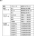
例えば、図17には、表情合成に使用することができるパラメータの例が示されている。図17に示すように、表情合成に使用することができるパラメータの種別には、感情パラメータ、パーツパラメータ、および口形素パラメータがある。 For example, FIG. 17 shows an example of parameters that can be used for facial expression synthesis. As shown in FIG. 17, the types of parameters that can be used for facial expression synthesis include emotion parameters, part parameters, and viseme parameters.
感情パラメータには、属性判別部34から出力される属性情報に含まれる笑顔スコアから求められる笑顔のパラメータ(笑い)の他、属性判別部34を利用して求められる悲しみパラメータ、および怒りパラメータがある。 The emotion parameters include a smile parameter (laughter) obtained from a smile score included in the attribute information output from the
パーツパラメータには、詳細パーツ検出部35から出力される55箇所のポイント(図5A参照)を利用して求められるまばたきパラメータ、眉毛パラメータ、眼球パラメータ、および口開閉パラメータがある。 The part parameters include a blink parameter, an eyebrow parameter, an eyeball parameter, and a mouth opening / closing parameter obtained using 55 points (see FIG. 5A) output from the detailed
口形素パラメータには、後述する図18の口形素母音判別部62から出力される母音判別スコアを利用して求められる口形素パラメータ「あ」、口形素パラメータ「い」、口形素パラメータ「う」、口形素パラメータ「え」、口形素パラメータ「お」、および口形素パラメータ「ん」がある。例えば、これらの口形素パラメータに基づいて、アバタの口形状を合成することで、ユーザの口の動きをより忠実にアバタに反映させることができる。 As the viseme parameters, a viseme parameter “A”, a viseme parameter “I”, and a viseme parameter “U” obtained using a vowel discrimination score output from the viseme
ここで、図18を参照して、口形素パラメータに基づいてアバタの口形状を合成する口形状合成処理について説明する。 Here, with reference to FIG. 18, the mouth shape synthesis process for synthesizing the mouth shape of the avatar based on the viseme parameters will be described.
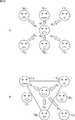
例えば、画像処理装置11には、口形状を合成するための母音の基本口形状が記憶されている。即ち、図18Aに示すように、母音「あ」、母音「い」、母音「う」、母音「え」、母音「お」、および母音「ん」を発音する際の基本的な口の形状が記憶されている。なお、「ん」の発音には、「p」の発音も含まれるものとする。 For example, the
そして、母音「あ」の口形素パラメータWa、母音「い」の口形素パラメータWi、母音「う」口形素パラメータWu、母音「え」の口形素パラメータWe、母音「お」の口形素パラメータWo、および母音「ん」の口形素パラメータWnを、それぞれの基本形状の重みとして口形状を合成することで、ユーザの口の動きをより忠実にアバタに反映させることができる。Then, the viseme parameter Wa of the vowel “A”, the viseme parameter Wi of the vowel “I”, the viseme parameter Wu of the vowel “U ”, the viseme parameter We of the vowel “E ”, and the By synthesizing the mouth shape using the viseme parameter Wo and the viseme parameter Wn of the vowel “n” as the weight of each basic shape, the movement of the user's mouth can be more faithfully reflected in the avatar. .
また、図18Bに示すように、母音「え」を発音する際の基本形状は、母音「い」を発音する際の基本形状と、母音「あ」を発音する際の基本形状とを合成することにより形成することができる。また、母音「お」を発音する際の基本形状は、母音「う」を発音する際の基本形状と、母音「あ」を発音する際の基本形状とを合成することにより形成することができる。 Further, as shown in FIG. 18B, the basic shape when the vowel “e” is pronounced is synthesized with the basic shape when the vowel “i” is pronounced and the basic shape when the vowel “a” is pronounced. Can be formed. In addition, the basic shape when the vowel “o” is pronounced can be formed by synthesizing the basic shape when the vowel “u” is pronounced and the basic shape when the vowel “a” is pronounced. .
従って、母音「あ」の口形素パラメータWa、母音「い」の口形素パラメータWi、母音「う」の口形素パラメータWu、および母音「ん」の口形素パラメータWnを、それぞれの基本形状の重みとして口形状を合成することでも、図18Aの例と同様に、ユーザの口の動きをより忠実にアバタに反映させることができる。また、このような処理を行うことにより、口形状を合成する処理で使用するパラメータを少なくすることができ、処理を簡略化することができる。また、記憶すべき母音の基本形状を少なくすることができる。Therefore, the viseme parameter Wa of the vowel “A”, the viseme parameter Wi of the vowel “I”, the viseme parameter Wu of the vowel “U ”, and the viseme parameter Wn of the vowel “n” are By synthesizing the mouth shape as the weight of the basic shape, the movement of the user's mouth can be more faithfully reflected on the avatar as in the example of FIG. 18A. Also, by performing such processing, it is possible to reduce the parameters used in the processing for synthesizing the mouth shape, and to simplify the processing. In addition, the basic shape of vowels to be stored can be reduced.
このような口形素パラメータは、例えば、詳細パーツ検出部35により検出される口の輪郭を特定するポイントから求めるとともに、例えば、音声認識を利用して求めることができる。 Such viseme parameters can be obtained from, for example, a point that specifies the contour of the mouth detected by the
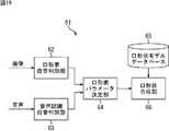
次に、図19は、口形素パラメータに基づいてアバタの口形状を合成する口形状合成処理部の構成例を示すブロック図である。 Next, FIG. 19 is a block diagram illustrating a configuration example of a mouth shape synthesis processing unit that synthesizes the mouth shape of the avatar based on the viseme parameters.
図19の口形状合成処理部61は、口形素母音判別部62、音声認識母音判別部63、口形素パラメータ決定部64、口形状モデルデータベース65、および口形状合成部66を備えて構成される。 The mouth shape
口形素母音判別部62には、詳細パーツ検出部35が画像から検出したユーザの口の輪郭を特定するポイントが供給され、口形素母音判別部62は、そのポイントから特定される口の形状を判別する。そして、口形素母音判別部62は、ユーザの口の形状を、図18に示したような母音「あ」、母音「い」、母音「う」、母音「え」、母音「お」、および母音「ん」の組み合わせで表現するときの、それぞれの母音の割合を示す母音判別スコアを口形素パラメータ決定部64に供給する。 The viseme
音声認識母音判別部63には、マイクなどの音声入力装置(図示せず)により入力された音声が供給され、音声認識母音判別部63は、その音声に対する音声認識処理により、ユーザが発した母音を判別し、母音判別スコアを口形素パラメータ決定部64に供給する。 The voice recognition
口形素パラメータ決定部64は、口形素母音判別部62からの母音判別スコアと、音声認識母音判別部63からの母音判別スコアとの、例えば、平均値を、口形素パラメータとして求め、口形状合成部66に供給する。なお、例えば、音声認識母音判別部63が用いられない場合には、口形素母音判別部62からの母音判別スコアが口形素パラメータとなる。 The viseme
口形状モデルデータベース65には、図18で説明したように、それぞれの母音ごとの基本口形状の三次元データが記憶されており、口形状合成部66は、それらの基本口形状の三次元データの各頂点を、それぞれ対応する母音の口形素パラメータで重み付け加算して、口形状を合成する。 As described with reference to FIG. 18, the mouth
このように、口形状合成処理部61においてアバタの口形状を合成し、レンダリング部53が、その口形状の三次元データをレンダリングすることで、アバタの口の形状を、ユーザの口の形状により近づけることができる。例えば、ユーザがしゃべる動作に従って、ユーザと同様の動作でしゃべるアバタを生成することができる。このようにアバタの口の形状をユーザに近づけることで、ユーザが、アバタとの一体感を感じるようになり、ディスプレイ13に表示される画像により素直に感情移入することができる。 As described above, the mouth shape
また、画像処理装置11では、図20に示すパラメータを用いて処理を行うことができる。図20には、画像処理装置11で使用されるパラメータの例が示されている。 Further, the
モデル選択パラメータには、年齢パラメータ、性別パラメータ、人種パラメータがあり、その他のパラメータには、メガネ有無パラメータがあり、それぞれ属性判別部34により判別される属性を利用して求められる。 The model selection parameters include an age parameter, a sex parameter, and a racial parameter, and other parameters include a spectacle presence / absence parameter, which are obtained using attributes determined by the
年齢パラメータは、画像に表示されている顔の年齢層(例えば、10代、20代、30代・・・などの年齢の幅に応じて分類される層や、子供(0〜10代)、大人(20〜50代)、老人(60台以上)などのように大まかに分類される層など)を表すパラメータである。例えば、属性判別部34は、画像に表示されている顔の属性を判別し、その顔が大人である度合い、子供である度合い、老人である度合いをそれぞれ数値化したスコアを出力し、それらのスコアに基づいて、年齢パラメータが決定される。そして、三次元データ管理部51が、年齢パラメータに従った年齢層のアバタの三次元データをレンダリング部53に供給することで、上述したような大人または子供により分けられたアバタよりも、よりユーザの年齢に近いアバタを表示することができる。 The age parameter is the age group of the face displayed in the image (for example, a layer classified according to the age range such as teens, 20s, 30s, etc., children (0 to 10s), It is a parameter that represents an adult (20 to 50s), an elderly person (60 or more), or a layer roughly classified. For example, the
性別パラメータは、画像に表示されている顔の性別(男性または女性)を表すパラメータである。 The gender parameter is a parameter representing the gender (male or female) of the face displayed in the image.
人種パラメータは、画像に表示されている顔の人種(例えば、白人や、黒人、黄色人種など)を表すパラメータである。例えば、属性判別部34は、画像に表示されている顔の属性を判別し、その顔の人種の度合いを数値化したスコアを出力し、そのスコアに基づいて、人種パラメータが決定される。そして、三次元データ管理部51が、人種パラメータに従った人種のテクスチャおよび三次元データをレンダリング部53に供給することで、よりユーザの顔に近いアバタを表示することができる。The race parameter is a parameter representing the race of the face displayed in the image (for example, white, black, yellow race, etc.). For example, the
メガネ有無パラメータは、画像に表示されている顔にメガネが掛けられているか否かを表すパラメータである。例えば、属性判別部34は、画像に表示されている顔にメガネが掛けられている度合いを数値化したスコアを出力し、それらのスコアに基づいて、メガネ有無パラメータが決定される。そして、三次元データ管理部51は、メガネ有無パラメータがメガネが掛けられていることを表しているとき、メガネの三次元データをレンダリング部53に供給することで、メガネを掛けたアバタを自動的に表示することができる。 The glasses presence / absence parameter is a parameter indicating whether or not glasses are put on the face displayed in the image. For example, the
なお、本実施の形態では、ユーザの属性(子供、男性、女性)に従って、自動的にアバタのモデルを選択しているが、ユーザの顔認識を高精度に行うことで、ユーザ個人を特定することができる場合には、例えば、ユーザが予め登録しておいたアバタを、ユーザの顔に置き換えて表示することができる。このように、顔認識によりユーザ個人を特定することで、例えば、ユーザが、自分のアバタを指定するような手間を省くことができる。これにより、現実空間と仮想空間(ディスプレイ13に表示される画像内の空間)とを、ユーザが、よりシームレスに感じるようになる。 In this embodiment, the avatar model is automatically selected according to the user attributes (child, male, female), but the user's face recognition is performed with high accuracy to identify the individual user. If it is possible, for example, an avatar registered in advance by the user can be replaced with the user's face and displayed. In this way, by identifying a user personally by face recognition, for example, it is possible to save time and effort for the user to specify his / her avatar. As a result, the user can feel the real space and the virtual space (the space in the image displayed on the display 13) more seamlessly.
また、画像処理装置11において判別されるユーザの属性は、上述した全てが含まれるものに限定されるのではなく、上述した属性のうちのいずれか1つが含まれていればよい。 Further, the user attributes determined by the
ところで、図1のパラメータ生成部17では、各パラメータ算出部から算出されるパラメータに対してフィルタ処理部42においてフィルタ処理が施されたパラメータが出力される。従って、例えば、各パラメータ算出部から算出されるパラメータに不安定な変動が含まれていたとしても、フィルタ処理部42によりパラメータの不安定な変動が除去され、安定化されたパラメータが出力される。これにより、画像生成部18が生成するアバタの挙動を滑らかに表現することができる。 Meanwhile, in the
しかしながら、フィルタ処理部42は、図7に示したような1段階のフィルタにより構成されているため、例えば、パラメータ生成部17のパラメータ算出部における演算に誤差が発生し、パラメータ算出部から出力されるパラメータに急激な大きな変動が含まれた場合、その急激な大きな変動を完全に除去することは困難である。これに対し、例えば、多段階のフィルタで構成されたフィルタ処理部を使用することで、パラメータに含まれている急激な大きな変動を低減させることができる。ところが、多段階のフィルタで構成されたフィルタ処理部を使用した場合には、フィルタ処理に時間が掛かり、例えば、ユーザの挙動に対する画像生成部18が生成するアバタの挙動にディレイが発生してしまう。 However, since the filter processing unit 42 is configured by a one-stage filter as shown in FIG. 7, for example, an error occurs in the calculation in the parameter calculation unit of the
そこで、パラメータ生成部17のパラメータ算出部における演算に誤差が発生し、パラメータ算出部から出力されるパラメータに急激な大きな変動が含まれた場合でも、その誤差による影響を排除することができるとともに、アバタの挙動にディレイが発生することのないフィルタ処理が要求される。 Therefore, even if an error occurs in the calculation in the parameter calculation unit of the
まず、図21を参照として、パラメータ生成部17において要求されるフィルタ処理の基本的な概念について説明する。なお、パラメータ生成部17の各パラメータ算出部(即ち、顔向きパラメータ算出部43、顔位置パラメータ算出部44、目閉率パラメータ算出部45、口開率パラメータ算出部46、および笑顔パラメータ算出部47)から出力されるパラメータは、顔認識部15による検出結果に基づいて、ユーザの顔の状態(顔の向き、顔の位置、目の開閉率、口の開閉率、笑顔の度合い)を推定した推定結果であり、以下、適宜、フィルタ処理における処理の対象となるパラメータを、状態推定結果値とも称する。 First, with reference to FIG. 21, a basic concept of filter processing required in the
図21には、3種類の正規分布が示されている。図21において、横軸は状態推定結果の値を表し、縦軸は確率を表している。 FIG. 21 shows three types of normal distributions. In FIG. 21, the horizontal axis represents the value of the state estimation result, and the vertical axis represents the probability.
正規分布曲線f(x)は、フィルタ処理の対象となる状態推定結果値ufを中心とした過去の状態推定結果値の誤差分布を表している。正規分布曲線r(x)は、状態推定結果値ufを処理の対象としたときのフィルタ処理の出力値を、直前までのフィルタ処理の結果から予測した出力予測値urを中心とした、その予測出力値urの尤度分布を表している。正規分布曲線f(x)および正規分布曲線r(x)は、正規分布曲線f(x)の標準偏差σf、および正規分布曲線r(x)の標準偏差σrを用いて、次の式(4)により表される。The normal distribution curve f (x) represents an error distribution of past state estimation result values centered on the state estimation result valueuf to be filtered. Normal distribution curve r (x) is the output value of the filter process when the target process state estimation result value uf, centered on the predicted output value ur predicted from the results of the filtering process immediately before, it represents the likelihood distribution of the predicted output value ur. Normal distribution curve f (x) and the normal distribution curve r (x), using the standard deviation sigmar of the standard deviation sigmaf of normal distribution curve f (x), and the normal distribution curver (x), the following equation It is represented by (4).
また、正規分布曲線p(x)は、正規分布曲線f(x)と正規分布曲線r(x)との積算により求められる正規分布であり、次の式(5)で表される。 The normal distribution curve p (x) is a normal distribution obtained by integrating the normal distribution curve f (x) and the normal distribution curve r (x), and is represented by the following equation (5).
そして、状態推定結果値xを変数として式(5)を整理すると、正規分布曲線p(x)は、次の式(6)で表される。 Then, when formula (5) is arranged using state estimation result value x as a variable, normal distribution curve p (x) is expressed by the following formula (6).
但し、式(6)において、upは正規分布曲線p(x)の期待値であり、フィルタ処理において出力される出力値となる。また、σpは正規分布曲線p(x)の標準偏差であり、定数KOは正規化項(定数)である。そして、出力値upおよび標準偏差σpは、次の式(7)で表される。However, in the formula (6), up is an expected value of the normal distribution curve p (x), the output value output in the filtering process. Σp is the standard deviation of the normal distribution curve p (x), and the constant KO is a normalization term (constant). The output value up and the standard deviation σp are expressed by the following equation (7).
次の式(7)に示すように、フィルタの出力値upは、正規分布曲線f(x)により表される誤差分布の分散(=σf2)と、正規分布曲線r(x)により表される尤度分布の分散(=σr2)との比で表される。As shown in the following equation (7), the output value up of the filter, the variance of the error distribution represented by the normal distribution curve f (x) and (= sigmaf2), the normal distribution curve r (x) Expressed as a ratio to the variance of the likelihood distribution expressed (= σr2 ).
そこで、例えば、フィルタ処理の対象となる状態推定結果値ufの信頼度を評価し、その評価を誤差分布の分散σf2と尤度分布の分散σr2とに反映させることで、状態推定結果値ufの信頼度に応じて状態推定結果値ufと出力予測値urとの間の値を適応的に出力するフィルタ処理を実現することができる。Therefore, for example, the reliability of the state estimation result value uf to be filtered is evaluated, and the evaluation is reflected in the variance σf2 of the error distribution and the variance σr2 of the likelihood distribution, thereby it is possible to realize a filtering process for outputting adaptively a value between the state estimation result value uf and the output prediction value ur in accordance with the reliability of the estimation result value uf.
なお、誤差分布の分散σf2と尤度分布の分散σr2との比は、相対的な値であるので、状態推定結果値ufの信頼性の評価を、いずれか一方に反映させればよく、本実施の形態では、誤差分布の分散σf2を、フィルタ処理の対象となる状態推定結果値ufの信頼性に応じて変動させるとともに、尤度分布の分散σr2を固定させて(予め設定された固定値を使用して)行われる処理について説明する。Note that since the ratio between the variance σf2 of the error distribution and the variance σr2 of the likelihood distribution is a relative value, the evaluation of the reliability of the state estimation result valueuf is reflected in either one. In this embodiment, the variance σf2 of the error distribution is changed according to the reliability of the state estimation result value uf to be filtered, and the variance σr2 of the likelihood distribution is changed. Processing that is performed in a fixed manner (using a preset fixed value) will be described.
ここで、図22に、誤差分布の分散σf2の変化と、フィルタの出力値upの変化との関係の一例を示す。Here, FIG. 22 shows the variance sigmaf2 of the change in the error distribution, an example of the relationship between the change in the output value up of the filter.
図22には、尤度分布の分散σr2を固定(σr=0.20)させ、誤差分布の分散σf2を変化(σf=0.20,0.40,0.05)させたときの正規分布曲線f(x)、正規分布曲線r(x)、および正規分布曲線p(x)が示されている。図22に示すように、誤差分布の分散σf2の値が大きければ、出力値upは出力予測値urに近い値になり、誤差分布の分散σf2の値が小さければ、出力値upは状態推定結果値ufに近い値になる。このように、誤差分布の分散σf2の変化させることにより、フィルタ処理の出力値upを適応的に変化させることができる。FIG. 22 shows a normal distribution curve f when the variance σr2 of the likelihood distribution is fixed (σr = 0.20) and the variance σf2 of the error distribution is changed (σf = 0.20,0.40,0.05). (X), normal distribution curve r (x), and normal distribution curve p (x) are shown. As shown in FIG. 22, the larger the value of the variance sigmaf2 of the error distribution, the output value up becomes a value close to the output prediction value ur, the smaller the value of the variance sigmaf2 of the error distribution, the output The value up is close to the state estimation result valueuf . Thus, by varying the variance sigmaf2 of the error distribution, it is possible to output value up of the filtering adaptively changed.
次に、誤差分布の分散σf2を設定する方法について説明する。Next, a method for setting the variance σf2 of the error distribution will be described.
正規分布曲線f(x)により表される誤差分布は、フィルタ処理の対象となる状態推定結果値ufの信頼度を表す指標となる。従って、上述したように誤差分布の分散σf2と尤度分布の分散σr2との比によりフィルタ処理の出力値upを決定するという処理を考慮すると、状態推定結果値ufの信頼度が低い場合には誤差分布の分散σf2を大きな値とし、状態推定結果値ufの信頼度が高い場合には誤差分布の分散σf2を小さな値とすることで、有効なフィルタ処理を行うことができる。The error distribution represented by the normal distribution curve f (x) is an index representing the reliability of the state estimation result valueuf to be filtered. Therefore, considering the process of determining the output value up of the filter processing based on the ratio of the variance σf2 of the error distribution and the variance σr2 of the likelihood distribution as described above, the reliability of the state estimation result value uf is considered. When the degree of error is low, the variance σf2 of the error distribution is set to a large value, and when the reliability of the state estimation result value uf is high, the variance σf2 of the error distribution is set to a small value. Processing can be performed.
このような状態推定結果値ufの信頼度に応じて誤差分布の分散σf2を変化させる処理を行うためには、状態推定結果値ufの信頼度を評価する必要がある。状態推定結果値ufの信頼度を評価する手法には、例えば、フィルタ処理による過去の出力値の履歴をサンプルとして、そのサンプルのバラツキを用いる手法がある。このような手法では、長時間にわたりバラツキの小さな値、即ち、一定値を保つ性質を持つ値が利用される。For the processing of changing the variance sigmaf2 of the error distribution in accordance with the reliability of this state estimation result value uf, it is necessary to evaluate the reliability of the state estimation result value uf. As a method of evaluating the reliability of the state estimation result valueuf , for example, there is a method of using the variation of the sample by using a history of past output values by the filter processing as a sample. In such a method, a value having a small variation over a long period of time, that is, a value having a property of maintaining a constant value is used.
例えば、状態推定結果値において、長時間にわたって一定値を保つ性質を持つ値として、状態推定結果値の加速度成分(二次微分値)を利用することができる。なお、局所的な期間を対象にすれば、一定値を保つ性質を持つ値として、速度成分を利用することも考えられるが、状態推定結果値の速度成分は、長時間にわたって徐々に変化する性質がある。 For example, the acceleration component (secondary differential value) of the state estimation result value can be used as a value having the property of maintaining a constant value for a long time in the state estimation result value. For local periods, the speed component may be used as a value that maintains a constant value. However, the speed component of the state estimation result value is a property that changes gradually over a long period of time. There is.
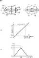
図23を参照して、状態推定結果値の加速度成分の分布と、状態推定結果値の速度成分の分布とを比較する。図23では、算出された加速度成分および速度成分がそれぞれ丸印(○)で示されており、それらの分布が曲線で示されている。 Referring to FIG. 23, the distribution of the acceleration component of the state estimation result value is compared with the distribution of the velocity component of the state estimation result value. In FIG. 23, the calculated acceleration component and velocity component are indicated by circles (◯), and their distributions are indicated by curves.
図23Aに示すように、状態推定結果値の加速度成分は、0.0を中心として前後に同じ程度にバラツキを有する分布となり、長時間にわたり一定の値を保つ性質であることが分かる。これに対し、図23Bに示すように、状態推定結果値の速度成分は、所定の値を中心としたバラツキを有する分布とはならず、長時間にわたって一定の値を保つ性質でないことが分かる。従って、状態推定結果値の加速度成分を、信頼度の評価に利用することで、安定的な結果を得ることができる。 As shown in FIG. 23A, it can be seen that the acceleration component of the state estimation result value has a distribution with the same degree of variation before and after 0.0 and maintains a constant value for a long time. On the other hand, as shown in FIG. 23B, it can be seen that the velocity component of the state estimation result value does not have a distribution centering on a predetermined value and does not have a property of maintaining a constant value for a long time. Therefore, a stable result can be obtained by using the acceleration component of the state estimation result value for the reliability evaluation.
例えば、時刻tの状態推定結果値uf(t)の加速度成分acc(t)は、時刻t−1の出力値up(t−1)および時刻t−2の出力値up(t−2)から、次の式(8)に示すように算出することができる。For example, the acceleration component acc (t) of the state estimation result value uf (t) at time t is the output value up (t−1) at time t−1 and the output value up (t− at time t−2). From 2), it can be calculated as shown in the following equation (8).
そして、時刻tの状態推定結果値uf(t)の加速度成分acc(t)の分散値var(t)は、時刻t−1までの加速度成分acc(t)から、次の式(9)で求められる。The variance value var (t) of the acceleration component acc (t) of the state estimation result value uf (t) at time t is expressed by the following equation (9) from the acceleration component acc (t) up to
式(8)および式(9)から分かるように、状態推定結果値の加速度成分の分散値var(t)は、フィルタの過去の出力値により更新される。 As can be seen from the equations (8) and (9), the variance value var (t) of the acceleration component of the state estimation result value is updated with the past output value of the filter.
このように過去のフィルタの出力値により更新される状態推定結果値の加速度成分の分散値var(t)と、時刻tでの状態推定結果値の加速度成分acc(t)を利用してマハラノビス距離を算出し、その2乗値を時刻tでの誤差分布の分散σf2とする。即ち、時刻tでの誤差分布の分散σf2(t)は、次の式(10)で求められる。As described above, the Mahalanobis distance is calculated using the variance value var (t) of the acceleration component of the state estimation result value updated by the output value of the past filter and the acceleration component acc (t) of the state estimation result value at time t. And the square value thereof is set as the variance σf2 of the error distribution at time t. That is, the variance σf2 (t) of the error distribution at time t is obtained by the following equation (10).
このように、処理対象の時刻tでの状態推定結果値uf(t)のフィルタ処理で用いられる誤差分布の分散σf2(t)が求められる。なお、上述したように、誤差分布の分散σf2と尤度分布の分散σr2との比は、相対的な値であるので、尤度分布の分散σr2には固定値を用いる。In this way, the variance σf2 (t) of the error distribution used in the filter processing of the state estimation result value uf (t) at the time t to be processed is obtained. As described above, since the ratio between the variance σf2 of the error distribution and the variance σr2 of the likelihood distribution is a relative value, a fixed value is used for the variance σr2 of the likelihood distribution. .
また、上述の式(7)に示したように、フィルタの出力値upを求めるには、予測出力値urを求める必要がある。次に、予測出力値urを求める方法について説明する。Further, as shown in Equation (7) above, to determine the output value up of the filter, it is necessary to obtain the predicted output value ur. Next, a method for obtaining the predictive output value ur.
予測出力値urは、状態推定結果値ufを処理の対象としたときのフィルタ処理の出力値を、直前までのフィルタ処理の結果から予測した値である。このような予測を行うには、運動モデルを仮定する必要があり、本実施の形態では、顔の変化状態が連続的な性質を示す場合が多いことを利用して、等速運動モデルを採用する。なお、状態推定結果値ufによっては、即ち、パラメータ生成部17において算出されるパラメータの種類によっては、等加速度運動(顔向き変化での速度変化への対応)などを利用することができ、予測出力値urを求める運動モデルは、必要に応じて適宜使い分けることができる。Predictive output value ur is the output value of the filter process when the target process state estimation result value uf, predicted from the results of the filtering process immediately before the value. In order to make such a prediction, it is necessary to assume a motion model, and in this embodiment, the constant velocity motion model is adopted by taking advantage of the fact that the face change state often shows a continuous property. To do. Depending on the state estimation result value uf , that is, depending on the type of parameter calculated by the
等速運度モデルを用いた予測では、フィルタ処理における直前の出力値と直前の加速度値とを用いて現在の出力値が予測され、時刻tでの予測出力値ur(t)は、次の式(11)により求められる。In the prediction using the constant velocity model, the current output value is predicted using the immediately preceding output value and the immediately preceding acceleration value in the filter processing, and the predicted output value ur (t) at time t is (11).
式(11)に示すように、時刻tの予測出力値ur(t)の算出には、フィルタの過去(時刻t−1および時刻t−2)の出力値up(t−1)および出力値up(t−2)が利用される。As shown in Expression (11), the predicted output value ur (t) at time t is calculated by using the output values up (t−1) of the past (time t−1 and time t−2) of the filter and The output value up (t−2) is used.
以上のように、正規分布曲線f(x)により表される誤差分布の分散(=σf2)、正規分布曲線r(x)により表される尤度分布の分散(=σr2)、および、直前までのフィルタ処理の結果から予測した出力予測値urが求められる。そして、上述の式(7)を演算することで、正規分布曲線p(x)の期待値、即ち、フィルタの出力値upを算出することができる。As described above, the variance of the error distribution represented by the normal distribution curve f (x) (= σf2 ), the variance of the likelihood distribution represented by the normal distribution curve r (x) (= σr2 ), and, the output prediction value ur predicted from the results of the filtering process immediately before is required. Then, by calculating the equation (7) above, the expected value of the normal distribution curve p (x), i.e., it is possible to calculate the output value up of the filter.
次に、図24は、フィルタ処理部のブロック図である。 Next, FIG. 24 is a block diagram of the filter processing unit.
図24において、フィルタ処理部71は、制御部72、加速度算出部73、加速度分散値更新部74、マハラノビス距離算出部75、記憶部76、予測部77、保持部78、フィルタ演算部79を備えて構成される。なお、フィルタ処理部71は、図1のフィルタ処理部42に替えて使用される。 24, the
制御部72には、図1のパラメータ生成部17の各パラメータ算出部から算出されるパラメータ、即ち、状態推定結果値ufが入力される。制御部72は、加速度算出部73およびフィルタ演算部79への状態推定結果値ufの供給の制御など、フィルタ処理部71の各部を制御する。なお、以下では、時刻tにおける処理、即ち、状態推定結果値uf(t)を処理対象としたフィルタ処理について説明する。A parameter calculated from each parameter calculation unit of the
加速度算出部73は、制御部72から状態推定結果値uf(t)が供給されるとともに、保持部78から時刻t−1の出力値up(t−1)および時刻t−2の出力値up(t−2)が供給される。そして、加速度算出部73は、上述の式(8)を演算することで、状態推定結果値uf(t)の加速度成分acc(t)を求め、加速度分散値更新部74およびマハラノビス距離算出部75に供給する。The
加速度分散値更新部74は、加速度算出部73から状態推定結果値uf(t)の加速度成分acc(t)が供給されると、上述の式(9)を演算することで、状態推定結果値の加速度成分の分散値var(t)を求め、マハラノビス距離算出部75に供給する。When the acceleration variance
マハラノビス距離算出部75は、加速度算出部73からの加速度成分acc(t)と、加速度分散値更新部74からの加速度成分の分散値var(t)とから、誤差分布の分散σf2を算出(上述の式(10)参照)し、フィルタ演算部79に供給する。The Mahalanobis
記憶部76には、固定値である尤度分布の分散σr2が記憶されており、フィルタ演算部79により尤度分布の分散σr2が記憶部76から読み出される。The
予測部77には、フィルタ処理部71から出力される出力値upが供給され、予測部77は、時刻t−1の出力値up(t−1)、および時刻t−2の出力値up(t−2)を用いて、上述の式(11)を演算することで、予測出力値ur(t)を求め、フィルタ処理部71に供給する。The
保持部78には、フィルタ処理部71から出力される出力値upが供給され、保持部78は、出力値upを保持し、出力値up(t−1)および出力値up(t−2)を加速度算出部73に供給する。The holding
フィルタ演算部79は、制御部72を介して供給される状態推定結果値uf(t)、マハラノビス距離算出部75から供給される誤差分布の分散σf2(t)、記憶部76から読み出した尤度分布の分散σr2、および予測部77から供給される予測出力値ur(t)に基づいて、上述の式(7)を演算する。これにより、フィルタ演算部79は、出力値up(t)を求めて出力する。The
ところで、フィルタ処理部71では、ある程度の加速度成分acc(サンプル)が蓄積されないと、状態推定結果値ufの信頼度を評価することができないため、制御部72は、所定数以上の加速度成分accが蓄積された後、フィルタ演算部79による演算結果が出力されるような制御を行う。Incidentally, since the
図25のフローチャートを参照して、フィルタ処理部71におけるフィルタ処理について説明する。なお、フィルタ処理部71のフィルタ処理は、図14のステップS22の処理として実行することができる。例えば、図14のステップS21の処理で、パラメータ生成部17の各パラメータ算出部からパラメータ、即ち、状態推定結果値uf(t)がフィルタ処理部71に供給されると処理が開始される。With reference to the flowchart of FIG. 25, the filter process in the
ステップS71において、制御部72は、供給された状態推定結果値uf(t)が、フィルタ処理の新規の対象であるか否かを判定する。In step S71, the
画像処理装置11では、画像に写されたユーザの顔ごとに処理が行われ、制御部72は、既にフィルタ処理の実行中の顔に対応付けられた状態推定結果値uf(t)が供給された場合には、フィルタ処理の新規の対象でないと判定する。一方、制御部72は、フィルタ処理の実行中の顔には対応付けられていない状態推定結果値uf(t)が供給された場合、即ち、顔の状態の推定が行われて1回目に算出された状態推定結果値uf(t)である場合(即ち、この場合、t=0)には、供給された状態推定結果値uf(t)が、フィルタ処理の新規の対象であると判定する。In the
ステップS71において、制御部72がフィルタ処理の新規の対象であると判定した場合、処理はステップS72に進み、制御部72は、フィルタ処理部71の各部の初期化を行う。例えば、制御部72は、加速度分散値更新部74、予測部77、フィルタ演算部79が処理に用いる内部変数(分散値var、予測出力値ur、出力値up)に初期値としての0をセットする。In step S71, when the
一方、ステップS71において、制御部72がフィルタ処理の新規の対象でないと判定した場合、処理はステップS73に進み、制御部72は、状態推定結果値uf(t)を加速度算出部73に供給する。また、加速度算出部73には、保持部78から時刻t−1の出力値up(t−1)および時刻t−2の出力値up(t−2)が供給される。そして、加速度算出部73は、状態推定結果値uf(t)、出力値up(t−1)、および出力値up(t−2)を用いて上述の式(8)を演算することで、状態推定結果値uf(t)の加速度成分acc(t)を求め、加速度分散値更新部74に供給する。On the other hand, if it is determined in step S71 that the
ステップS73の処理後、処理はステップS74において、加速度分散値更新部74は、ステップS73で加速度算出部73から供給された加速度成分acc(t)を用いて、上述の式(9)を演算することで、状態推定結果値の加速度成分の分散値var(t)を求め、処理はステップS75に進む。 After the process of step S73, in step S74, the acceleration variance
ステップS75において、制御部72は、加速度成分acc(t)を十分に蓄積したか否か、即ち、ステップS74で算出した分散値var(t)は、状態推定結果値ufの信頼度を評価することができる程度の加速度成分acc(t)の個数から求められたものであるか否かを判定する。即ち、状態推定結果値ufの信頼度を評価するためには、ある程度の個数の加速度成分acc(t)から求められた分散値var(t)が必要であり、制御部72には、その個数が閾値(例えば、20個)として予め設定されている。従って、制御部72は、加速度分散値更新部74が分散値var(t)を求めるのに用いた加速度成分acc(t)の個数が閾値以上であれば、加速度成分acc(t)を十分に蓄積したと判定する。一方、制御部72は、加速度分散値更新部74分散値var(t)を求めるのに用いた加速度成分acc(t)の個数が閾値未満であれば、加速度成分acc(t)を十分に蓄積していないと判定する。In step S75, the
なお、ステップS73の処理で保持部78から供給される時刻t−2の出力値up(t−2)を用いるため、ステップS73乃至S75の処理は、ステップS71で新規の対象と判定されてから2フレーム後(即ち、出力値up(t−2)が出力された後)の画像を対象として処理が行われ、ステップS71で新規の対象と判定されてから2フレームが出力されるまでは、ステップS73乃至S75をスキップしてステップS76が行われる。Since the output value up (t−2) at time t−2 supplied from the holding
ステップS72の処理後、または、ステップS75で制御部72が加速度成分acc(t)を十分に蓄積していないと判定した場合、処理はステップS76に進む。ステップS76において、制御部72は、出力値up(t)として、供給された状態推定結果値uf(t)をそのまま出力するとともに、出力値up(t)を予測部77および保持部78に供給する。即ち、この場合、状態推定結果値ufの信頼度を正確に評価することができないため、フィルタ処理部71において出力値upの算出は行われない。ステップS76の処理後、フィルタ処理は終了し、次のフレームを対象とした処理が行われる。After the process of step S72, or when the
一方、ステップS75において、制御部72が加速度成分acc(t)を十分に蓄積したと判定した場合、処理はステップS77に進む。ステップS77において、制御部72は、ステップS73で算出された加速度成分acc(t)およびステップS74で算出された分散値var(t)をマハラノビス距離算出部75に供給するように、加速度算出部73および加速度分散値更新部74を制御する。そして、マハラノビス距離算出部75は、加速度成分acc(t)および分散値var(t)から誤差分布の分散σf2を算出し、フィルタ演算部79に供給して、処理はステップS78に進む。On the other hand, when the
ステップS78において、予測部77は、時刻t−1の出力値up(t−1)、および時刻t−2の出力値up(t−2)を用いて、上述の式(11)を演算することで、予測出力値urを求め、フィルタ処理部71に供給する。In step S78, the
ステップS78の処理後、処理はステップS79に進み、制御部72は状態推定結果値uf(t)をフィルタ演算部79に供給し、フィルタ演算部79は記憶部76から尤度分布の分散σr2を読み出す。そして、フィルタ演算部79は、状態推定結果値uf(t)、尤度分布の分散σr2、ステップS77で供給された誤差分布の分散σf2、およびステップS78で供給された予測出力値urに基づいて、上述の式(7)を演算して出力値up(t)を求めて出力し、フィルタ処理は終了する。After the process of step S78, the process proceeds to step S79, where the
以上のように、フィルタ処理部71では、パラメータ生成部17のパラメータ算出部における演算に誤差が発生し、パラメータ算出部から出力されるパラメータ(状態推定結果値)に急激な大きな変動が含まれたとしても、その変動を抑制することができる。即ち、そのように変動するパラメータは信頼度(分散σf2)が低いので、フィルタ処理部71は、予測出力値を出力することで、演算誤差などによる変動を抑制することができる。これにより、ロバスト性の高い安定的なフィルタ処理を施すことができる。また、上述したように、多段階のフィルタで構成されたフィルタ処理部を使用した場合に発生するようなディレイも防止することができる。As described above, in the
また、フィルタ処理部71においてフィルタ処理が施されたパラメータを使用して画像生成部18がアバタを生成することにより、ユーザの顔の状態変化に対して高い追従性を有するとともに、パラメータの演算誤差などにより発生するアバタの震え(パラメータの不安定な変動)を抑制し、より自然でスムーズなアバタの動きを表現することができる。 In addition, since the
なお、上述のフィルタ処理についての説明では、1つのパラメータに対して処理が行われているが、パラメータ生成部17の各パラメータ算出部から算出される複数のパラメータに対して、状態ベクトルと共分散行列とを利用することにより、それらのパラメータを統合的に用いることができる。即ち、状態ベクトルを利用することで、各状態(パラメータ)間の相互作用効果が得られるため、よりロバスト性の高いフィルタ処理を実現することができる。 In the above description of the filter processing, processing is performed for one parameter. However, for a plurality of parameters calculated from each parameter calculation unit of the
上述した一連の処理は、ハードウエアにより実行することもできるし、ソフトウエアにより実行することもできる。一連の処理をソフトウエアにより実行する場合には、そのソフトウエアを構成するプログラムが、専用のハードウエアに組み込まれているコンピュータ、または、各種のプログラムをインストールすることで、各種の機能を実行することが可能な、例えば汎用のパーソナルコンピュータなどに、プログラム記録媒体からインストールされる。 The series of processes described above can be executed by hardware or can be executed by software. When a series of processing is executed by software, a program constituting the software executes various functions by installing a computer incorporated in dedicated hardware or various programs. For example, it is installed from a program recording medium in a general-purpose personal computer or the like.
図26は、上述した一連の処理をプログラムにより実行するコンピュータのハードウエアの構成例を示すブロック図である。 FIG. 26 is a block diagram illustrating an example of a hardware configuration of a computer that executes the series of processes described above according to a program.
コンピュータにおいて、CPU(Central Processing Unit)101,ROM(Read Only Memory)102,RAM(Random Access Memory)103は、バス104により相互に接続されている。 In a computer, a CPU (Central Processing Unit) 101, a ROM (Read Only Memory) 102, and a RAM (Random Access Memory) 103 are connected to each other via a
バス104には、さらに、入出力インタフェース105が接続されている。入出力インタフェース105には、キーボード、マウス、マイクロホンなどよりなる入力部106、ディスプレイ、スピーカなどよりなる出力部107、ハードディスクや不揮発性のメモリなどよりなる記憶部108、ネットワークインタフェースなどよりなる通信部109、磁気ディスク、光ディスク、光磁気ディスク、或いは半導体メモリなどのリムーバブルメディア111を駆動するドライブ110が接続されている。 An input /
以上のように構成されるコンピュータでは、CPU101が、例えば、記憶部108に記憶されているプログラムを、入出力インタフェース105及びバス104を介して、RAM103にロードして実行することにより、上述した一連の処理が行われる。 In the computer configured as described above, the
コンピュータ(CPU101)が実行するプログラムは、例えば、磁気ディスク(フレキシブルディスクを含む)、光ディスク(CD-ROM(Compact Disc-Read Only Memory),DVD(Digital Versatile Disc)等)、光磁気ディスク、もしくは半導体メモリなどよりなるパッケージメディアであるリムーバブルメディア111に記録して、あるいは、ローカルエリアネットワーク、インタネット、デジタル衛星放送といった、有線または無線の伝送媒体を介して提供される。 The program executed by the computer (CPU 101) is, for example, a magnetic disk (including a flexible disk), an optical disk (CD-ROM (Compact Disc-Read Only Memory), DVD (Digital Versatile Disc), etc.), a magneto-optical disk, or a semiconductor. The program is recorded on a
そして、プログラムは、リムーバブルメディア111をドライブ110に装着することにより、入出力インタフェース105を介して、記憶部108にインストールすることができる。また、プログラムは、有線または無線の伝送媒体を介して、通信部109で受信し、記憶部108にインストールすることができる。その他、プログラムは、ROM102や記憶部108に、あらかじめインストールしておくことができる。 The program can be installed in the
なお、コンピュータが実行するプログラムは、本明細書で説明する順序に沿って時系列に処理が行われるプログラムであっても良いし、並列に、あるいは呼び出しが行われたとき等の必要なタイミングで処理が行われるプログラムであっても良い。また、プログラムは、1のCPUにより処理されるものであっても良いし、複数のCPUによって分散処理されるものであっても良い。 The program executed by the computer may be a program that is processed in time series in the order described in this specification, or in parallel or at a necessary timing such as when a call is made. It may be a program for processing. The program may be processed by one CPU, or may be distributedly processed by a plurality of CPUs.
なお、本発明の実施の形態は、上述した実施の形態に限定されるものではなく、本発明
の要旨を逸脱しない範囲において種々の変更が可能である。The embodiment of the present invention is not limited to the above-described embodiment, and various modifications can be made without departing from the gist of the present invention.
11 画像処理装置, 12 カメラ, 13 ディスプレイ, 14 カメラ入力部, 15 顔認識部, 16 モデル選択部, 17 パラメータ生成部, 18 画像生成部, 21 カメラ制御部, 22 デコード部, 31 顔認識制御部, 32 顔検出処理部, 33 パーツ検出部, 34 属性判別部, 35 詳細パーツ検出部, 41 顔向き補正処理部, 42 フィルタ処理部, 43 顔向きパラメータ算出部, 44 顔位置パラメータ算出部, 45 目閉率パラメータ算出部, 46 口開率パラメータ算出部, 47 笑顔パラメータ算出部, 51 三次元データ管理部, 52 シェーダ管理部, 53 レンダリング部, 54 合成処理部, 61 口形状合成処理部, 62 口形素母音判別部, 63 音声認識母音判別部, 64 口形素パラメータ決定部, 65 口形状モデルデータベース, 66 口形状合成部, 71 フィルタ処理部, 72 制御部, 73 加速度算出部, 74 加速度分散値更新部, 75 マハラノビス距離算出部, 76 記憶部, 77 予測部, 78 保持部, 79 フィルタ演算部 DESCRIPTION OF
Claims (7)
Translated fromJapanese前記顔検出手段により検出された顔領域内にある顔のパーツの位置を検出するパーツ検出手段と、
前記パーツ検出手段により検出された前記パーツの配置に基づいて、前記顔の属性を判別し、その判別結果を示すスコアを求める判別手段と、
前記判別手段により求められた前記スコアに基づいて、前記画像のユーザの顔に置き換えて表示させるモデルを選択するモデル選択手段と、
前記モデル選択手段により選択されたモデルの顔の画像を生成し、そのモデルの顔の画像を、前記顔領域内にあるユーザの顔に合成する画像生成手段と、
前記顔検出手段により検出される顔領域内のユーザの顔の状態を推定するパラメータを算出するパラメータ出力手段と、
前記パラメータ出力手段から出力されるパラメータに対してフィルタ処理を施すフィルタ処理手段と
を備え、
前記フィルタ処理手段は、
前記パラメータ出力手段から出力された処理対象の前記パラメータの信頼度を、処理対象の前記パラメータについての加速度成分と、処理対象の前記パラメータ以前のパラメータについて過去に算出された加速度成分の分散値とに基づいて算出する信頼度算出手段と、
過去の前記フィルタ処理手段からの出力値に基づいて、処理対象の前記パラメータにフィルタ処理を施したときに出力される出力値を予測した予測出力値を求める予測手段と、
処理対象の前記パラメータと前記予測手段が求めた前記予測出力値とを、前記信頼度算出手段により算出される前記信頼度に応じた重み付け加算により、前記フィルタ処理の結果として出力される出力値を演算するフィルタ演算手段と
を有する
画像処理装置。Face detection means for detecting a face region from an image showing a user's face;
Parts detection means for detecting the position of a facial part within the face area detected by the face detection means;
Based on the arrangement of the parts detected by the parts detection means, a determination means for determining the attribute of the face and obtaining a score indicating the determination result;
Model selection means for selecting a model to be displayed in place of the face of the user of the image based on the score obtained by the determination means;
Generating an image of the model face selected by the model selection means, and combining the face image of the model with the face of the user in the face area;
Parameter output means for calculating a parameter for estimating the face state of the user in the face area detected by the face detection means;
Filter processing means for performing filter processing on the parameter output from the parameter output means;
With
The filter processing means includes
The reliability of the parameter to be processed output from the parameter output means is set to an acceleration component for the parameter to be processed and a variance value of acceleration components calculated in the past for parameters before the parameter to be processed. A reliability calculation means to calculate based on;
Prediction means for obtaining a predicted output value that predicts an output value that is output when filter processing is performed on the parameter to be processed, based on past output values from the filter processing means;
An output value output as a result of the filtering process is obtained by weighting addition of the parameter to be processed and the predicted output value obtained by the prediction unit according to the reliability calculated by the reliability calculation unit. Filter calculation means for calculating
An image processing apparatus.
請求項1に記載の画像処理装置。The image processing apparatus according to claim 1, wherein the face attribute determined by the determination unit is at least one of an age group and a sex.
前記顔検出手段により検出される顔領域内のユーザの顔の方向が、前記顔検出手段により検出可能な検出範囲の境界近傍である場合、前記第1の顔方向情報の時間変動と、前記第2の顔方向情報の時間変動とに基づいて、前記画像生成手段で生成するモデルの顔の方向を制御するパラメータを選択する顔方向パラメータ選択手段
をさらに備える請求項1に記載の画像処理装置。The face detection means outputs first face direction information indicating the direction of the user's face, and the parts detection means indicates a second face direction indicating the direction of the user's face according to the arrangement of the parts. Output information,
When the face direction of the user in the face area detected by the face detection means is near the boundary of the detection range detectable by the face detection means, the time variation of the first face direction information and the first The image processing apparatus according to claim 1, further comprising: a face direction parameter selecting unit that selects a parameter for controlling a face direction of the model generated by the image generating unit based on time variation of the face direction information of 2.
前記口形状検出手段により検出された前記複数のポイントから、前記ユーザの口の形状を判別し、その口形状を、所定数の母音の組み合わせで表現するときのそれぞれの母音の割合を示す母音パラメータを出力する母音判別手段と、
前記所定数の母音の口形状の基本となるモデルを、それぞれのモデルに対応する前記母音パラメータで重み付けて合成する口形状合成部と
をさらに備える請求項1に記載の画像処理装置。Mouth shape detecting means for detecting a plurality of points specifying the mouth shape of the user's face;
A vowel parameter indicating the proportion of each vowel when the mouth shape of the user is determined from the plurality of points detected by the mouth shape detection means and the mouth shape is expressed by a combination of a predetermined number of vowels Vowel discrimination means for outputting
The image processing apparatus according to claim 1, further comprising: a mouth shape synthesis unit that weights and synthesizes a model that is a basis of the mouth shape of the predetermined number of vowels with the vowel parameter corresponding to each model.
前記フィルタ処理手段は、前記パラメータ出力手段から出力される複数のパラメータを総合的に用いてフィルタ処理を行う
請求項1に記載の画像処理装置。The parameter output means outputs a plurality of parameters for estimating a plurality of states of the user's face,
The filter processing unit performs a filter process by comprehensively using a plurality of parameters output from the parameter output unit.
The image processing apparatus according toclaim 1 .
前記顔領域内にある顔のパーツの位置を検出し、
前記パーツの配置に基づいて、前記顔の属性を判別し、その判別結果を示すスコアを求め、
前記スコアに基づいて、前記画像のユーザの顔に置き換えて表示させるモデルを選択し、
前記選択されたモデルの顔の画像を生成し、そのモデルの顔の画像を、前記顔領域内にあるユーザの顔に合成し、
前記顔領域内のユーザの顔の状態を推定するパラメータを算出し、
前記パラメータに対してフィルタ処理を施す
ステップを含み、
前記フィルタ処理を施すステップでは、
処理対象の前記パラメータの信頼度を、処理対象の前記パラメータについての加速度成分と、処理対象の前記パラメータ以前のパラメータについて過去に算出された加速度成分の分散値とに基づいて算出し、
過去の出力値に基づいて、処理対象の前記パラメータにフィルタ処理を施したときに出力される出力値を予測した予測出力値を求め、
処理対象の前記パラメータと前記予測出力値とを、前記信頼度に応じた重み付け加算により、前記フィルタ処理の結果として出力される出力値を演算する
ステップを有する
画像処理方法。Detect the face area from the image showing the user's face,
Detect the position of the facial parts within the face area,
Based on the arrangement of the parts, determine the attribute of the face, obtain a score indicating the determination result,
Based on the score, select a model to be displayed in place of the user's face of the image,
Generating an image of the face of the selected model, and combining the face image of the model with the face of the user within the face area;
Calculating a parameter for estimating the face state of the user in the face region;
Filter the parameters
Including steps,
In the step of applying the filtering process,
The reliability of the parameter to be processed is calculated based on the acceleration component for the parameter to be processed and the variance value of the acceleration component calculated in the past for the parameter before the parameter to be processed,
Based on the past output value, obtain a predicted output value that predicts the output value that is output when the parameter to be processed is filtered,
An output value output as a result of the filtering process is calculated by weighting and adding the parameter to be processed and the predicted output value according to the reliability.
An image processing method includingsteps .
前記顔領域内にある顔のパーツの位置を検出し、
前記パーツの配置に基づいて、前記顔の属性を判別し、その判別結果を示すスコアを求め、
前記スコアに基づいて、前記画像のユーザの顔に置き換えて表示させるモデルを選択し、
前記選択されたモデルの顔の画像を生成し、そのモデルの顔の画像を、前記顔領域内にあるユーザの顔に合成し、
前記顔領域内のユーザの顔の状態を推定するパラメータを算出し、
前記パラメータに対してフィルタ処理を施す
ステップを含み、
前記フィルタ処理を施すステップでは、
処理対象の前記パラメータの信頼度を、処理対象の前記パラメータについての加速度成分と、処理対象の前記パラメータ以前のパラメータについて過去に算出された加速度成分の分散値とに基づいて算出し、
過去の出力値に基づいて、処理対象の前記パラメータにフィルタ処理を施したときに出力される出力値を予測した予測出力値を求め、
処理対象の前記パラメータと前記予測出力値とを、前記信頼度に応じた重み付け加算により、前記フィルタ処理の結果として出力される出力値を演算する
ステップを有する
画像処理をコンピュータに実行させるプログラム。Detect the face area from the image showing the user's face,
Detect the position of the facial parts within the face area,
Based on the arrangement of the parts, determine the attribute of the face, obtain a score indicating the determination result,
Based on the score, select a model to be displayed in place of the user's face of the image,
Generating an image of the face of the selected model, and combining the face image of the model with the face of the user within the face area;
Calculating a parameter for estimating the face state of the user in the face region;
Filter the parameters
Including steps,
In the step of applying the filtering process,
The reliability of the parameter to be processed is calculated based on the acceleration component for the parameter to be processed and the variance value of the acceleration component calculated in the past for the parameter before the parameter to be processed,
Based on the past output value, obtain a predicted output value that predicts the output value that is output when the parameter to be processed is filtered,
An output value output as a result of the filtering process is calculated by weighting and adding the parameter to be processed and the predicted output value according to the reliability.
A program for causing a computer to execute image processing includingsteps .
Priority Applications (4)
| Application Number | Priority Date | Filing Date | Title |
|---|---|---|---|
| JP2009284807AJP5423379B2 (en) | 2009-08-31 | 2009-12-16 | Image processing apparatus, image processing method, and program |
| US12/829,870US8634658B2 (en) | 2009-08-31 | 2010-07-02 | Apparatus, method, and program for processing image |
| CN2010102420292ACN102004897B (en) | 2009-08-31 | 2010-07-29 | Apparatus and method for processing image |
| EP10173731.0AEP2293221B1 (en) | 2009-08-31 | 2010-08-23 | Apparatus, method, and program for processing image |
Applications Claiming Priority (3)
| Application Number | Priority Date | Filing Date | Title |
|---|---|---|---|
| JP2009201028 | 2009-08-31 | ||
| JP2009201028 | 2009-08-31 | ||
| JP2009284807AJP5423379B2 (en) | 2009-08-31 | 2009-12-16 | Image processing apparatus, image processing method, and program |
Publications (3)
| Publication Number | Publication Date |
|---|---|
| JP2011070623A JP2011070623A (en) | 2011-04-07 |
| JP2011070623A5 JP2011070623A5 (en) | 2013-01-17 |
| JP5423379B2true JP5423379B2 (en) | 2014-02-19 |
Family
ID=43304648
Family Applications (1)
| Application Number | Title | Priority Date | Filing Date |
|---|---|---|---|
| JP2009284807AExpired - Fee RelatedJP5423379B2 (en) | 2009-08-31 | 2009-12-16 | Image processing apparatus, image processing method, and program |
Country Status (4)
| Country | Link |
|---|---|
| US (1) | US8634658B2 (en) |
| EP (1) | EP2293221B1 (en) |
| JP (1) | JP5423379B2 (en) |
| CN (1) | CN102004897B (en) |
Families Citing this family (72)
| Publication number | Priority date | Publication date | Assignee | Title |
|---|---|---|---|---|
| US8359642B1 (en)* | 2010-06-25 | 2013-01-22 | Sprint Communications Company L.P. | Restricting mature content |
| US20110316697A1 (en)* | 2010-06-29 | 2011-12-29 | General Electric Company | System and method for monitoring an entity within an area |
| KR20120011920A (en)* | 2010-07-27 | 2012-02-09 | 삼성전자주식회사 | Digital video signal processing apparatus, digital video signal processing method and recording medium recording the method |
| JP2012244526A (en)* | 2011-05-23 | 2012-12-10 | Sony Corp | Information processing device, information processing method, and computer program |
| US9088426B2 (en) | 2011-12-13 | 2015-07-21 | Google Inc. | Processing media streams during a multi-user video conference |
| CN104115503A (en)* | 2011-12-29 | 2014-10-22 | 英特尔公司 | Communication using avatars |
| US9888171B2 (en)* | 2012-02-13 | 2018-02-06 | Htc Corporation | Mobile camera device capable of improving facial patterns of a captured image |
| CN104170374A (en) | 2012-03-14 | 2014-11-26 | 谷歌公司 | Modify the appearance of participants during a video conference |
| JP5880182B2 (en)* | 2012-03-19 | 2016-03-08 | カシオ計算機株式会社 | Image generating apparatus, image generating method, and program |
| US9595298B2 (en) | 2012-07-18 | 2017-03-14 | Microsoft Technology Licensing, Llc | Transforming data to create layouts |
| JP2014068107A (en)* | 2012-09-25 | 2014-04-17 | Zenrin Datacom Co Ltd | Image processing apparatus, image processing system, image processing method, and computer program |
| WO2014080678A1 (en)* | 2012-11-22 | 2014-05-30 | ソニー株式会社 | Information processing device, system, information processing method and program |
| CN103903292B (en)* | 2012-12-27 | 2017-04-19 | 北京新媒传信科技有限公司 | Method and system for realizing head portrait editing interface |
| JP6268722B2 (en)* | 2013-03-06 | 2018-01-31 | 日本電気株式会社 | Display device, display method, and program |
| WO2014187919A1 (en)* | 2013-05-23 | 2014-11-27 | bioMérieux | Method, system and computer program product for producing a raised relief map from images of an object |
| US9202119B2 (en)* | 2013-10-18 | 2015-12-01 | Daon Holdings Limited | Methods and systems for determining user liveness |
| US20150317511A1 (en)* | 2013-11-07 | 2015-11-05 | Orbeus, Inc. | System, method and apparatus for performing facial recognition |
| CN104657974A (en)* | 2013-11-25 | 2015-05-27 | 腾讯科技(上海)有限公司 | Image processing method and device |
| US9614724B2 (en) | 2014-04-21 | 2017-04-04 | Microsoft Technology Licensing, Llc | Session-based device configuration |
| US9639742B2 (en) | 2014-04-28 | 2017-05-02 | Microsoft Technology Licensing, Llc | Creation of representative content based on facial analysis |
| US9773156B2 (en)* | 2014-04-29 | 2017-09-26 | Microsoft Technology Licensing, Llc | Grouping and ranking images based on facial recognition data |
| US10111099B2 (en) | 2014-05-12 | 2018-10-23 | Microsoft Technology Licensing, Llc | Distributing content in managed wireless distribution networks |
| US9874914B2 (en) | 2014-05-19 | 2018-01-23 | Microsoft Technology Licensing, Llc | Power management contracts for accessory devices |
| US10037202B2 (en) | 2014-06-03 | 2018-07-31 | Microsoft Technology Licensing, Llc | Techniques to isolating a portion of an online computing service |
| US9460493B2 (en) | 2014-06-14 | 2016-10-04 | Microsoft Technology Licensing, Llc | Automatic video quality enhancement with temporal smoothing and user override |
| US9373179B2 (en) | 2014-06-23 | 2016-06-21 | Microsoft Technology Licensing, Llc | Saliency-preserving distinctive low-footprint photograph aging effect |
| US9717006B2 (en) | 2014-06-23 | 2017-07-25 | Microsoft Technology Licensing, Llc | Device quarantine in a wireless network |
| JP6476608B2 (en)* | 2014-06-30 | 2019-03-06 | カシオ計算機株式会社 | Operation processing apparatus, operation processing method, and program |
| US9444999B2 (en)* | 2014-08-05 | 2016-09-13 | Omnivision Technologies, Inc. | Feature detection in image capture |
| US9626768B2 (en)* | 2014-09-30 | 2017-04-18 | Microsoft Technology Licensing, Llc | Optimizing a visual perspective of media |
| US10282069B2 (en) | 2014-09-30 | 2019-05-07 | Microsoft Technology Licensing, Llc | Dynamic presentation of suggested content |
| WO2016114392A1 (en) | 2015-01-15 | 2016-07-21 | 日本電気株式会社 | Information output device, camera, information output system, information output method, and program |
| DE102015223175A1 (en)* | 2015-11-24 | 2017-05-24 | Conti Temic Microelectronic Gmbh | Driver assistance system with adaptive environment image data processing |
| WO2017137952A1 (en)* | 2016-02-10 | 2017-08-17 | Vats Nitin | Intelligent chatting on digital communication network |
| JP6794144B2 (en)* | 2016-06-03 | 2020-12-02 | 東芝テック株式会社 | Operation input device, sales data processing device and program |
| US10452896B1 (en)* | 2016-09-06 | 2019-10-22 | Apple Inc. | Technique for creating avatar from image data |
| DK179978B1 (en) | 2016-09-23 | 2019-11-27 | Apple Inc. | Image data for enhanced user interactions |
| JP2018055619A (en)* | 2016-09-30 | 2018-04-05 | 株式会社ブイシンク | Image display device |
| JP6266736B1 (en) | 2016-12-07 | 2018-01-24 | 株式会社コロプラ | Method for communicating via virtual space, program for causing computer to execute the method, and information processing apparatus for executing the program |
| CN108268227B (en)* | 2017-01-04 | 2020-12-01 | 京东方科技集团股份有限公司 | display screen |
| EP3557865A4 (en) | 2017-01-23 | 2020-01-08 | NTT DoCoMo, Inc. | INFORMATION PROCESSING SYSTEM AND PROCESSING PROCESS |
| US10380228B2 (en) | 2017-02-10 | 2019-08-13 | Microsoft Technology Licensing, Llc | Output generation based on semantic expressions |
| KR102439054B1 (en)* | 2017-05-16 | 2022-09-02 | 애플 인크. | Record and send emojis |
| KR101966384B1 (en)* | 2017-06-29 | 2019-08-13 | 라인 가부시키가이샤 | Method and system for image processing |
| US10870056B2 (en)* | 2017-11-01 | 2020-12-22 | Sony Interactive Entertainment Inc. | Emoji-based communications derived from facial features during game play |
| US11068141B1 (en)* | 2018-02-02 | 2021-07-20 | Snap Inc. | Device-based image modification of depicted objects |
| US11553009B2 (en)* | 2018-02-07 | 2023-01-10 | Sony Corporation | Information processing device, information processing method, and computer program for switching between communications performed in real space and virtual space |
| KR102661019B1 (en) | 2018-02-23 | 2024-04-26 | 삼성전자주식회사 | Electronic device providing image including 3d avatar in which motion of face is reflected by using 3d avatar corresponding to face and method for operating thefeof |
| JP2019164614A (en)* | 2018-03-20 | 2019-09-26 | 株式会社ViRD | Avatar control program |
| JP6941800B2 (en) | 2018-04-04 | 2021-09-29 | パナソニックIpマネジメント株式会社 | Emotion estimation device, emotion estimation method and program |
| US12033296B2 (en) | 2018-05-07 | 2024-07-09 | Apple Inc. | Avatar creation user interface |
| DK179874B1 (en) | 2018-05-07 | 2019-08-13 | Apple Inc. | USER INTERFACE FOR AVATAR CREATION |
| KR102530264B1 (en)* | 2018-08-08 | 2023-05-09 | 삼성전자 주식회사 | Apparatus and method for providing item according to attribute of avatar |
| CN109447894A (en)* | 2018-08-20 | 2019-03-08 | 广州市久邦数码科技有限公司 | A kind of image processing method and its system based on data analysis |
| CN111079479A (en) | 2018-10-19 | 2020-04-28 | 北京市商汤科技开发有限公司 | Child state analysis method and device, vehicle, electronic equipment, storage medium |
| US11107261B2 (en) | 2019-01-18 | 2021-08-31 | Apple Inc. | Virtual avatar animation based on facial feature movement |
| CN111488759A (en)* | 2019-01-25 | 2020-08-04 | 北京字节跳动网络技术有限公司 | Image processing method and device for animal face |
| KR102664688B1 (en)* | 2019-02-19 | 2024-05-10 | 삼성전자 주식회사 | Method for providing shoot mode based on virtual character and electronic device performing thereof |
| JP7295388B2 (en)* | 2019-03-08 | 2023-06-21 | フリュー株式会社 | Image processing device, image processing method and image processing program |
| EP3942544A1 (en)* | 2019-03-22 | 2022-01-26 | Essilor International | Device for simulating a physiological behaviour of a mammal using a virtual mammal, process and computer program |
| DK201970530A1 (en) | 2019-05-06 | 2021-01-28 | Apple Inc | Avatar integration with multiple applications |
| CN110674765A (en)* | 2019-09-27 | 2020-01-10 | 上海依图网络科技有限公司 | Imaging system and video processing method |
| JP7319172B2 (en)* | 2019-11-13 | 2023-08-01 | 富士フイルム株式会社 | IMAGE PROCESSING APPARATUS, IMAGE PROCESSING METHOD AND IMAGE PROCESSING SYSTEM |
| CN111698552A (en)* | 2020-05-15 | 2020-09-22 | 完美世界(北京)软件科技发展有限公司 | Video resource generation method and device |
| CN115917474A (en) | 2020-06-08 | 2023-04-04 | 苹果公司 | Rendering avatars in three-dimensional environments |
| CN111833418B (en)* | 2020-07-14 | 2024-03-29 | 北京百度网讯科技有限公司 | Animation interaction method, device, equipment and storage medium |
| CN112001932B (en)* | 2020-09-01 | 2023-10-31 | 腾讯科技(深圳)有限公司 | Face recognition method, device, computer equipment and storage medium |
| US11438551B2 (en)* | 2020-09-15 | 2022-09-06 | At&T Intellectual Property I, L.P. | Virtual audience using low bitrate avatars and laughter detection |
| JP7217838B2 (en)* | 2020-09-24 | 2023-02-03 | 三菱電機株式会社 | Mouth opening calculator |
| JP7613906B2 (en)* | 2020-12-18 | 2025-01-15 | トヨタ自動車株式会社 | Image Processing System |
| WO2022261482A1 (en)* | 2021-06-10 | 2022-12-15 | EyesMatch Ltd. | System and method for digital optician measurements |
| KR102826023B1 (en)* | 2022-11-30 | 2025-06-27 | 주식회사 케이티 | Device, method and computer program for generating face image based om voice data |
Family Cites Families (26)
| Publication number | Priority date | Publication date | Assignee | Title |
|---|---|---|---|---|
| US6332123B1 (en)* | 1989-03-08 | 2001-12-18 | Kokusai Denshin Denwa Kabushiki Kaisha | Mouth shape synthesizing |
| JPH0744727A (en) | 1993-07-27 | 1995-02-14 | Sony Corp | Method and device for generating picture |
| JP2000306095A (en)* | 1999-04-16 | 2000-11-02 | Fujitsu Ltd | Image collation / search system |
| IT1320002B1 (en)* | 2000-03-31 | 2003-11-12 | Cselt Centro Studi Lab Telecom | PROCEDURE FOR THE ANIMATION OF A SYNTHESIZED VOLTOHUMAN MODEL DRIVEN BY AN AUDIO SIGNAL. |
| JP2002108382A (en)* | 2000-09-27 | 2002-04-10 | Sony Corp | Animation method and device for performing lip sinchronization |
| JP2002232783A (en) | 2001-02-06 | 2002-08-16 | Sony Corp | Image processor, method therefor and record medium for program |
| US20030007700A1 (en)* | 2001-07-03 | 2003-01-09 | Koninklijke Philips Electronics N.V. | Method and apparatus for interleaving a user image in an original image sequence |
| GB2382289B (en)* | 2001-09-28 | 2005-07-06 | Canon Kk | Method and apparatus for generating models of individuals |
| JP3822828B2 (en)* | 2002-03-20 | 2006-09-20 | 沖電気工業株式会社 | Three-dimensional image generation apparatus, image generation method thereof, and computer-readable recording medium recording the image generation program |
| JP2003308533A (en)* | 2002-04-17 | 2003-10-31 | Mitsubishi Electric Corp | Driver's face image processing device |
| US7133535B2 (en)* | 2002-12-21 | 2006-11-07 | Microsoft Corp. | System and method for real time lip synchronization |
| US7711155B1 (en)* | 2003-04-14 | 2010-05-04 | Videomining Corporation | Method and system for enhancing three dimensional face modeling using demographic classification |
| KR100839772B1 (en)* | 2003-07-15 | 2008-06-20 | 오므론 가부시키가이샤 | Target determination device and imaging device |
| JP4517633B2 (en) | 2003-11-25 | 2010-08-04 | ソニー株式会社 | Object detection apparatus and method |
| JP4482796B2 (en) | 2004-03-26 | 2010-06-16 | ソニー株式会社 | Information processing apparatus and method, recording medium, and program |
| JP2006064973A (en)* | 2004-08-26 | 2006-03-09 | Crimson Technology Inc | Control system |
| US7634106B2 (en)* | 2004-09-22 | 2009-12-15 | Fujifilm Corporation | Synthesized image generation method, synthesized image generation apparatus, and synthesized image generation program |
| DE602006009191D1 (en)* | 2005-07-26 | 2009-10-29 | Canon Kk | Imaging device and method |
| US20070080967A1 (en)* | 2005-10-11 | 2007-04-12 | Animetrics Inc. | Generation of normalized 2D imagery and ID systems via 2D to 3D lifting of multifeatured objects |
| US7728866B2 (en)* | 2005-11-03 | 2010-06-01 | Broadcom Corp. | Video telephony image processing |
| JP2007156650A (en) | 2005-12-01 | 2007-06-21 | Sony Corp | Image processing unit |
| JP2007213182A (en)* | 2006-02-08 | 2007-08-23 | Fujifilm Corp | Object state recognition method, apparatus, and program |
| JP4093273B2 (en)* | 2006-03-13 | 2008-06-04 | オムロン株式会社 | Feature point detection apparatus, feature point detection method, and feature point detection program |
| JP2008021266A (en)* | 2006-07-14 | 2008-01-31 | Matsushita Electric Ind Co Ltd | Face orientation detection device, face orientation detection method, and face orientation detection program |
| JP4424364B2 (en)* | 2007-03-19 | 2010-03-03 | ソニー株式会社 | Image processing apparatus and image processing method |
| JP4569670B2 (en)* | 2008-06-11 | 2010-10-27 | ソニー株式会社 | Image processing apparatus, image processing method, and program |
- 2009
- 2009-12-16JPJP2009284807Apatent/JP5423379B2/ennot_activeExpired - Fee Related
- 2010
- 2010-07-02USUS12/829,870patent/US8634658B2/enactiveActive
- 2010-07-29CNCN2010102420292Apatent/CN102004897B/ennot_activeExpired - Fee Related
- 2010-08-23EPEP10173731.0Apatent/EP2293221B1/ennot_activeNot-in-force
Also Published As
| Publication number | Publication date |
|---|---|
| EP2293221A2 (en) | 2011-03-09 |
| EP2293221A3 (en) | 2014-04-23 |
| US20110052081A1 (en) | 2011-03-03 |
| EP2293221B1 (en) | 2018-11-28 |
| CN102004897A (en) | 2011-04-06 |
| US8634658B2 (en) | 2014-01-21 |
| JP2011070623A (en) | 2011-04-07 |
| CN102004897B (en) | 2013-11-27 |
Similar Documents
| Publication | Publication Date | Title |
|---|---|---|
| JP5423379B2 (en) | Image processing apparatus, image processing method, and program | |
| US10559111B2 (en) | Systems and methods for generating computer ready animation models of a human head from captured data images | |
| US10169905B2 (en) | Systems and methods for animating models from audio data | |
| US10198845B1 (en) | Methods and systems for animating facial expressions | |
| US20240013462A1 (en) | Audio-driven facial animation with emotion support using machine learning | |
| US11831980B2 (en) | Electronic device and controlling method of electronic device | |
| US8692830B2 (en) | Automatic avatar creation | |
| US20190340419A1 (en) | Generation of Parameterized Avatars | |
| US8150205B2 (en) | Image processing apparatus, image processing method, program, and data configuration | |
| US8233789B2 (en) | Dynamic exposure metering based on face detection | |
| US20180121733A1 (en) | Reducing computational overhead via predictions of subjective quality of automated image sequence processing | |
| KR20170047167A (en) | Method and apparatus for converting an impression of a face in video | |
| KR20120005587A (en) | Method and apparatus for generating facial animation in computer system | |
| CN110910479B (en) | Video processing method, device, electronic equipment and readable storage medium | |
| WO2023279713A1 (en) | Special effect display method and apparatus, computer device, storage medium, computer program, and computer program product | |
| CN112684881B (en) | Avatar facial expression generation system and avatar facial expression generation method | |
| US11869150B1 (en) | Avatar modeling and generation | |
| KR101913811B1 (en) | A method for analysing face information, and an appratus for analysing face information to present faces, identify mental status or compensate it | |
| USRE50538E1 (en) | Automatic avatar creation | |
| US20250200771A1 (en) | Image processing device and operating method thereof | |
| Fang et al. | Manitalk: manipulable talking head generation from single image in the wild | |
| CN105303596A (en) | Movement processing apparatus and movement processing method | |
| JP2005196519A (en) | Image processor and image processing method, recording medium, and program | |
| KR20210153502A (en) | Electronic device and controlling method of electronic device | |
| WO2025167492A1 (en) | Expression transfer method and apparatus, electronic device and computer readable storage medium |
Legal Events
| Date | Code | Title | Description |
|---|---|---|---|
| A521 | Request for written amendment filed | Free format text:JAPANESE INTERMEDIATE CODE: A523 Effective date:20121126 | |
| A621 | Written request for application examination | Free format text:JAPANESE INTERMEDIATE CODE: A621 Effective date:20121126 | |
| A977 | Report on retrieval | Free format text:JAPANESE INTERMEDIATE CODE: A971007 Effective date:20130801 | |
| A131 | Notification of reasons for refusal | Free format text:JAPANESE INTERMEDIATE CODE: A131 Effective date:20130813 | |
| A521 | Request for written amendment filed | Free format text:JAPANESE INTERMEDIATE CODE: A523 Effective date:20131002 | |
| TRDD | Decision of grant or rejection written | ||
| A01 | Written decision to grant a patent or to grant a registration (utility model) | Free format text:JAPANESE INTERMEDIATE CODE: A01 Effective date:20131029 | |
| A61 | First payment of annual fees (during grant procedure) | Free format text:JAPANESE INTERMEDIATE CODE: A61 Effective date:20131111 | |
| R151 | Written notification of patent or utility model registration | Ref document number:5423379 Country of ref document:JP Free format text:JAPANESE INTERMEDIATE CODE: R151 | |
| R250 | Receipt of annual fees | Free format text:JAPANESE INTERMEDIATE CODE: R250 | |
| R250 | Receipt of annual fees | Free format text:JAPANESE INTERMEDIATE CODE: R250 | |
| R250 | Receipt of annual fees | Free format text:JAPANESE INTERMEDIATE CODE: R250 | |
| LAPS | Cancellation because of no payment of annual fees |