JP5423184B2 - Filtration membrane module cleaning method and cleaning apparatus - Google Patents
Filtration membrane module cleaning method and cleaning apparatusDownload PDFInfo
- Publication number
- JP5423184B2 JP5423184B2JP2009159188AJP2009159188AJP5423184B2JP 5423184 B2JP5423184 B2JP 5423184B2JP 2009159188 AJP2009159188 AJP 2009159188AJP 2009159188 AJP2009159188 AJP 2009159188AJP 5423184 B2JP5423184 B2JP 5423184B2
- Authority
- JP
- Japan
- Prior art keywords
- filtration membrane
- membrane module
- air
- module
- cleaning
- Prior art date
- Legal status (The legal status is an assumption and is not a legal conclusion. Google has not performed a legal analysis and makes no representation as to the accuracy of the status listed.)
- Expired - Fee Related
Links
- 239000012528membraneSubstances0.000titleclaimsdescription184
- 238000001914filtrationMethods0.000titleclaimsdescription181
- 238000004140cleaningMethods0.000titleclaimsdescription105
- 238000000034methodMethods0.000titleclaimsdescription52
- 239000000126substanceSubstances0.000claimsdescription76
- 239000000243solutionSubstances0.000claimsdescription65
- 239000007788liquidSubstances0.000claimsdescription46
- 238000006243chemical reactionMethods0.000claimsdescription40
- 238000005201scrubbingMethods0.000claimsdescription28
- 238000005273aerationMethods0.000claimsdescription9
- 239000012466permeateSubstances0.000claimsdescription7
- 238000002347injectionMethods0.000claimsdescription6
- 239000007924injectionSubstances0.000claimsdescription6
- XLYOFNOQVPJJNP-UHFFFAOYSA-NwaterSubstancesOXLYOFNOQVPJJNP-UHFFFAOYSA-N0.000description34
- 239000010802sludgeSubstances0.000description19
- 239000000706filtrateSubstances0.000description10
- 239000003344environmental pollutantSubstances0.000description8
- 231100000719pollutantToxicity0.000description8
- 239000010865sewageSubstances0.000description8
- 238000005406washingMethods0.000description8
- 239000005708Sodium hypochloriteSubstances0.000description7
- 238000007654immersionMethods0.000description7
- SUKJFIGYRHOWBL-UHFFFAOYSA-Nsodium hypochloriteChemical compound[Na+].Cl[O-]SUKJFIGYRHOWBL-UHFFFAOYSA-N0.000description7
- 238000000926separation methodMethods0.000description6
- 238000011001backwashingMethods0.000description5
- 230000000694effectsEffects0.000description5
- 238000009434installationMethods0.000description5
- 239000002033PVDF binderSubstances0.000description4
- 229920002981polyvinylidene fluoridePolymers0.000description4
- MUBZPKHOEPUJKR-UHFFFAOYSA-NOxalic acidChemical compoundOC(=O)C(O)=OMUBZPKHOEPUJKR-UHFFFAOYSA-N0.000description3
- 238000005345coagulationMethods0.000description3
- 230000015271coagulationEffects0.000description3
- 239000012510hollow fiberSubstances0.000description3
- 239000010842industrial wastewaterSubstances0.000description3
- 238000011144upstream manufacturingMethods0.000description3
- CURLTUGMZLYLDI-UHFFFAOYSA-NCarbon dioxideChemical compoundO=C=OCURLTUGMZLYLDI-UHFFFAOYSA-N0.000description2
- 238000009825accumulationMethods0.000description2
- QVGXLLKOCUKJST-UHFFFAOYSA-Natomic oxygenChemical compound[O]QVGXLLKOCUKJST-UHFFFAOYSA-N0.000description2
- 238000010276constructionMethods0.000description2
- 239000000356contaminantSubstances0.000description2
- 238000007599dischargingMethods0.000description2
- 238000000605extractionMethods0.000description2
- 239000007789gasSubstances0.000description2
- 239000000463materialSubstances0.000description2
- 239000001301oxygenSubstances0.000description2
- 229910052760oxygenInorganic materials0.000description2
- 239000011148porous materialSubstances0.000description2
- 238000004062sedimentationMethods0.000description2
- 239000002351wastewaterSubstances0.000description2
- BZSXEZOLBIJVQK-UHFFFAOYSA-N2-methylsulfonylbenzoic acidChemical compoundCS(=O)(=O)C1=CC=CC=C1C(O)=OBZSXEZOLBIJVQK-UHFFFAOYSA-N0.000description1
- IJGRMHOSHXDMSA-UHFFFAOYSA-NAtomic nitrogenChemical compoundN#NIJGRMHOSHXDMSA-UHFFFAOYSA-N0.000description1
- MYMOFIZGZYHOMD-UHFFFAOYSA-NDioxygenChemical compoundO=OMYMOFIZGZYHOMD-UHFFFAOYSA-N0.000description1
- 238000005276aeratorMethods0.000description1
- 239000001569carbon dioxideSubstances0.000description1
- 229910002092carbon dioxideInorganic materials0.000description1
- 239000000701coagulantSubstances0.000description1
- 230000003111delayed effectEffects0.000description1
- 238000010586diagramMethods0.000description1
- 238000010790dilutionMethods0.000description1
- 239000012895dilutionSubstances0.000description1
- 229910001873dinitrogenInorganic materials0.000description1
- 229910001882dioxygenInorganic materials0.000description1
- 239000000428dustSubstances0.000description1
- 239000012530fluidSubstances0.000description1
- 238000011086high cleaningMethods0.000description1
- 239000003295industrial effluentSubstances0.000description1
- 230000007774longtermEffects0.000description1
- 239000008155medical solutionSubstances0.000description1
- 229910052751metalInorganic materials0.000description1
- 239000002184metalSubstances0.000description1
- 150000007524organic acidsChemical class0.000description1
- 235000006408oxalic acidNutrition0.000description1
- 238000001556precipitationMethods0.000description1
- 238000003756stirringMethods0.000description1
- 230000001629suppressionEffects0.000description1
Images
Classifications
- B—PERFORMING OPERATIONS; TRANSPORTING
- B01—PHYSICAL OR CHEMICAL PROCESSES OR APPARATUS IN GENERAL
- B01D—SEPARATION
- B01D63/00—Apparatus in general for separation processes using semi-permeable membranes
- B—PERFORMING OPERATIONS; TRANSPORTING
- B01—PHYSICAL OR CHEMICAL PROCESSES OR APPARATUS IN GENERAL
- B01D—SEPARATION
- B01D61/00—Processes of separation using semi-permeable membranes, e.g. dialysis, osmosis or ultrafiltration; Apparatus, accessories or auxiliary operations specially adapted therefor
- B01D61/14—Ultrafiltration; Microfiltration
- B01D61/18—Apparatus therefor
- B—PERFORMING OPERATIONS; TRANSPORTING
- B01—PHYSICAL OR CHEMICAL PROCESSES OR APPARATUS IN GENERAL
- B01D—SEPARATION
- B01D65/00—Accessories or auxiliary operations, in general, for separation processes or apparatus using semi-permeable membranes
- B01D65/02—Membrane cleaning or sterilisation ; Membrane regeneration
- C—CHEMISTRY; METALLURGY
- C02—TREATMENT OF WATER, WASTE WATER, SEWAGE, OR SLUDGE
- C02F—TREATMENT OF WATER, WASTE WATER, SEWAGE, OR SLUDGE
- C02F3/00—Biological treatment of water, waste water, or sewage
- C02F3/02—Aerobic processes
- C02F3/12—Activated sludge processes
- C02F3/1236—Particular type of activated sludge installations
- C02F3/1268—Membrane bioreactor systems
- C02F3/1273—Submerged membrane bioreactors
- C—CHEMISTRY; METALLURGY
- C02—TREATMENT OF WATER, WASTE WATER, SEWAGE, OR SLUDGE
- C02F—TREATMENT OF WATER, WASTE WATER, SEWAGE, OR SLUDGE
- C02F3/00—Biological treatment of water, waste water, or sewage
- C02F3/30—Aerobic and anaerobic processes
- C02F3/302—Nitrification and denitrification treatment
- B—PERFORMING OPERATIONS; TRANSPORTING
- B01—PHYSICAL OR CHEMICAL PROCESSES OR APPARATUS IN GENERAL
- B01D—SEPARATION
- B01D2313/00—Details relating to membrane modules or apparatus
- B01D2313/20—Specific housing
- B01D2313/205—Specific housing characterised by the shape
- B—PERFORMING OPERATIONS; TRANSPORTING
- B01—PHYSICAL OR CHEMICAL PROCESSES OR APPARATUS IN GENERAL
- B01D—SEPARATION
- B01D2315/00—Details relating to the membrane module operation
- B01D2315/06—Submerged-type; Immersion type
- B—PERFORMING OPERATIONS; TRANSPORTING
- B01—PHYSICAL OR CHEMICAL PROCESSES OR APPARATUS IN GENERAL
- B01D—SEPARATION
- B01D2321/00—Details relating to membrane cleaning, regeneration, sterilization or to the prevention of fouling
- B01D2321/04—Backflushing
- B—PERFORMING OPERATIONS; TRANSPORTING
- B01—PHYSICAL OR CHEMICAL PROCESSES OR APPARATUS IN GENERAL
- B01D—SEPARATION
- B01D2321/00—Details relating to membrane cleaning, regeneration, sterilization or to the prevention of fouling
- B01D2321/16—Use of chemical agents
- B—PERFORMING OPERATIONS; TRANSPORTING
- B01—PHYSICAL OR CHEMICAL PROCESSES OR APPARATUS IN GENERAL
- B01D—SEPARATION
- B01D2321/00—Details relating to membrane cleaning, regeneration, sterilization or to the prevention of fouling
- B01D2321/18—Use of gases
- B01D2321/185—Aeration
- C—CHEMISTRY; METALLURGY
- C02—TREATMENT OF WATER, WASTE WATER, SEWAGE, OR SLUDGE
- C02F—TREATMENT OF WATER, WASTE WATER, SEWAGE, OR SLUDGE
- C02F2203/00—Apparatus and plants for the biological treatment of water, waste water or sewage
- C02F2203/002—Apparatus and plants for the biological treatment of water, waste water or sewage comprising an initial buffer container
- Y—GENERAL TAGGING OF NEW TECHNOLOGICAL DEVELOPMENTS; GENERAL TAGGING OF CROSS-SECTIONAL TECHNOLOGIES SPANNING OVER SEVERAL SECTIONS OF THE IPC; TECHNICAL SUBJECTS COVERED BY FORMER USPC CROSS-REFERENCE ART COLLECTIONS [XRACs] AND DIGESTS
- Y02—TECHNOLOGIES OR APPLICATIONS FOR MITIGATION OR ADAPTATION AGAINST CLIMATE CHANGE
- Y02W—CLIMATE CHANGE MITIGATION TECHNOLOGIES RELATED TO WASTEWATER TREATMENT OR WASTE MANAGEMENT
- Y02W10/00—Technologies for wastewater treatment
- Y02W10/10—Biological treatment of water, waste water, or sewage
Landscapes
- Chemical & Material Sciences (AREA)
- Chemical Kinetics & Catalysis (AREA)
- Engineering & Computer Science (AREA)
- Water Supply & Treatment (AREA)
- Life Sciences & Earth Sciences (AREA)
- Biodiversity & Conservation Biology (AREA)
- Microbiology (AREA)
- Hydrology & Water Resources (AREA)
- Environmental & Geological Engineering (AREA)
- Organic Chemistry (AREA)
- Separation Using Semi-Permeable Membranes (AREA)
Description
Translated fromJapanese本発明は、下排水や産業排水中の汚濁物質等を生物処理又は凝集沈殿処理する反応槽に浸漬して濾過操作を行う濾過膜モジュールの洗浄方法および洗浄装置に関するものである。 The present invention relates to a cleaning method and a cleaning apparatus for a filtration membrane module that performs a filtration operation by immersing a pollutant or the like in sewage wastewater or industrial wastewater in a reaction tank for biological treatment or coagulation sedimentation treatment.
下排水や産業排水中の汚濁物質等を生物処理又は凝集沈殿処理し、濾過膜モジュールで濾過する膜分離処理システムにおいては、反応槽中に濾過膜モジュールを浸漬し、濾過操作により被濾過水を膜分離する。 In a membrane separation treatment system that performs biological treatment or coagulation sedimentation treatment of pollutants in sewage and industrial wastewater, and filters them with a filtration membrane module, the filtration membrane module is immersed in a reaction tank and filtered water is filtered. Membrane separation.
濾過操作によって、濾過膜モジュールの膜面および膜面内部細孔部には、除去された汚濁物質等が付着、堆積する。通常、膜面への汚濁物質等の付着や堆積を抑制することにより濾過操作時間を長く継続させ濾過運転の効率を上げる目的で、濾過膜モジュールの底部から曝気を行い、膜面に激しい気泡流を衝突させて付着・堆積の抑制を図るためにスクラビングエアを供給する。また、あわせて、一定周期で濾過水を濾過膜モジュールに加圧通水して汚れを逆洗除去する。しかし、スクラビングエアと逆洗によっても長期にわたる抑制効果には、限界がある。そのため、スクラビングエアや逆洗によっても膜面に徐々に付着、堆積する汚濁物質等を定期的に除去するため、付着、堆積する汚濁物質等を反応除去する薬液洗浄を行なうことが必須となる。 By the filtration operation, the removed pollutant and the like adhere to and deposit on the membrane surface of the membrane filter module and the pores inside the membrane surface. Normally, in order to keep the filtration operation time longer and to improve the efficiency of the filtration operation by suppressing the adhesion and accumulation of pollutants on the membrane surface, aeration is performed from the bottom of the filtration membrane module, and intense bubble flow on the membrane surface. Scrubbing air is supplied in order to prevent adhesion and accumulation by colliding. At the same time, the filtered water is pressurized and passed through the membrane filter module at a fixed period to remove the dirt backwashing. However, there is a limit to the long-term suppression effect even by scrubbing air and backwashing. For this reason, in order to periodically remove contaminants that gradually adhere to and deposit on the film surface even by scrubbing air or backwashing, it is essential to perform chemical cleaning that reacts and removes the contaminants that adhere and deposit.
薬液としては、付着、堆積する汚濁物質等が有機物による場合には、次亜塩素酸ナトリウムが広く用いられ、無機物による場合には、シュウ酸が用いられる。 As the chemical liquid, sodium hypochlorite is widely used when the pollutant or the like deposited or deposited is organic, and oxalic acid is used when it is inorganic.
そして、この薬液を用いた濾過膜モジュール洗浄方法として、インライン洗浄とオンエア洗浄が知られている。 Inline cleaning and on-air cleaning are known as membrane membrane cleaning methods using this chemical solution.
インライン洗浄は、反応槽に浸漬した濾過膜モジュールを浸漬したままの状態で、濾過膜モジュールの2次側(濾過水取り出し側)から次亜塩素酸ナトリウム溶液等の薬液を注入して、該薬液を濾過膜モジュールの1次側(被濾過水供給側)へ浸透、透過させて濾過膜モジュールを薬液洗浄する方法である(以下、第1の洗浄方法)。 In-line cleaning is performed by injecting a chemical solution such as sodium hypochlorite solution from the secondary side (filtrated water removal side) of the filtration membrane module while the filtration membrane module immersed in the reaction tank is immersed. Is permeated and permeated into the primary side (filtered water supply side) of the filtration membrane module to perform chemical cleaning of the filtration membrane module (hereinafter referred to as a first cleaning method).
オンエア洗浄方法は、濾過膜モジュールを気中に曝した状態で、濾過膜モジュールの2次側から次亜塩素酸ナトリウム溶液等の薬液を注入して、該薬液を濾過膜モジュールの2次側から1次側へ浸透、透過させて濾過膜モジュールを薬液洗浄する方法である。 In the on-air cleaning method, a chemical solution such as a sodium hypochlorite solution is injected from the secondary side of the filtration membrane module while the filtration membrane module is exposed to the air, and the chemical solution is injected from the secondary side of the filtration membrane module. In this method, the filtration membrane module is permeated and permeated to the primary side to perform chemical cleaning.
具体的には、オンエア洗浄方法には、主として以下の3つの方法が知られている。 Specifically, the following three methods are mainly known as the on-air cleaning method.
その1は、浸漬している反応槽から濾過膜モジュールを引き抜いて、気中に曝し、濾過膜モジュールの2次側から次亜塩素酸ナトリウム溶液等の薬液を注入して、該薬液を濾過膜モジュールの2次側から1次側へ浸透、透過させて濾過膜モジュールを薬液洗浄する方法である(以下、第2の洗浄方法)。 The first is that the filtration membrane module is pulled out from the submerged reaction tank and exposed to the air, and a chemical solution such as a sodium hypochlorite solution is injected from the secondary side of the filtration membrane module, and the chemical solution is removed from the filtration membrane. In this method, the membrane filter is permeated and permeated from the secondary side to the primary side of the module to clean the filtration membrane module (hereinafter referred to as a second cleaning method).
その2は、濾過膜モジュールを浸漬している反応槽から、槽内液を排出し、反応槽内にて濾過膜モジュールを気中に曝した状態で、濾過膜モジュールの2次側から次亜塩素酸ナトリウム溶液等の薬液を注入して、該薬液を濾過膜モジュールの1次側へ浸透、透過させて濾過膜モジュールを薬液洗浄する方法である(以下、第3の洗浄方法)。 The second is that the liquid in the tank is discharged from the reaction tank in which the filtration membrane module is immersed, and the filtration membrane module is exposed to the air in the reaction tank. This is a method of injecting a chemical solution such as a sodium chlorate solution and allowing the chemical solution to permeate and permeate the primary side of the filtration membrane module to wash the filtration membrane module (hereinafter, a third cleaning method).
その3は、反応槽とは別に、濾過膜モジュール専用に浸漬させる槽を設けた外付け浸漬槽方式により、汚濁物質等の処理を行なう場合に、この方式での薬液洗浄は、外付け浸漬槽の槽内液だけを排出することでよいため、上記第3の洗浄方法に較べて排出液の量を低減でき、さらに、排出液を反応槽に一時的に貯留する方法をとった上で、濾過膜モジュールを上記第3の洗浄方法と同じ薬液洗浄する方法が取れる(以下、第4の洗浄方法)。
上記洗浄方法を開示したものとして、例えば特許文献1がある。The third is that, in the case of processing the pollutant and the like by an external immersion tank system provided with a tank dedicated to the filtration membrane module separately from the reaction tank, the chemical solution cleaning in this system is an external immersion tank. Since only the liquid in the tank needs to be discharged, the amount of the discharged liquid can be reduced as compared with the third cleaning method, and further, after taking a method of temporarily storing the discharged liquid in the reaction tank, The same chemical cleaning method as the third cleaning method can be used for the filtration membrane module (hereinafter referred to as a fourth cleaning method).
For example, Patent Document 1 discloses the above-described cleaning method.
上記第1の洗浄方法(インライン洗浄方法)は、濾過膜モジュールを反応槽の槽内液中に浸漬させた状態で薬液を注入するため、反応槽内での液圧により薬液が濾過膜モジュール内に浸透し難く、さらに、濾過膜モジュールの表面で浸透・透過後の薬液は、槽内液により薬液濃度は希釈されるため、濾過膜モジュールの膜面部分に付着・堆積した汚濁物質等の洗浄効果は減じられる。また、濾過膜モジュールに目詰まりが生じている場合に、該目詰まり部分には薬液が行き渡らずに洗浄斑が発生する。洗浄斑を無くすためには、薬液をより高圧で多量に濾過膜モジュールに注入しなければならず、高圧ポンプと多量の薬液を必要とする。 In the first cleaning method (in-line cleaning method), the chemical solution is injected in a state where the filtration membrane module is immersed in the liquid in the reaction tank. In addition, the chemical solution that has permeated and permeated on the surface of the filtration membrane module is diluted by the solution in the tank, so cleaning of contaminated substances attached to and deposited on the membrane surface of the filtration membrane module The effect is reduced. Moreover, when clogging has arisen in the filtration membrane module, the chemical | medical solution does not spread over this clogging part but a cleaning spot generate | occur | produces. In order to eliminate cleaning spots, a chemical solution must be injected into the filtration membrane module in a large amount at a higher pressure, which requires a high-pressure pump and a large amount of chemical solution.
上記第2の洗浄方法(オンエア洗浄方法)は、濾過膜モジュールを反応槽から引き抜いて、気中に移動させるために、チェーンブロックなどの昇降機器を使用する必要があり、また、濾過水配管やスクラビング用エア配管等の取り外し作業等や洗浄終了後の取り付け等の煩雑な作業が必要となる。 In the second cleaning method (on-air cleaning method), it is necessary to use a lifting device such as a chain block in order to pull out the filtration membrane module from the reaction tank and move it in the air. It is necessary to perform complicated operations such as removing the scrubbing air pipe and installing it after completion of cleaning.
上記第3の洗浄方法(オンエア洗浄方法)は、反応槽から引き抜いた槽内液を一時的に溜めておく貯留槽が別途必要となる。通常、濾過膜モジュールは、水深4〜5mの反応槽の底部まで浸漬されているので、濾過膜モジュール全体を気中に曝すためには、反応槽の槽内液をほぼ全量抜き出すこととなり、抜き出した槽内液を一時的に貯留する大容量の槽や移送用ポンプ等の設備や設置による建設費や運転費の増大につながる。 The third cleaning method (on-air cleaning method) requires a separate storage tank for temporarily storing the liquid in the tank extracted from the reaction tank. Usually, since the filtration membrane module is immersed to the bottom of the reaction tank having a water depth of 4 to 5 m, in order to expose the entire filtration membrane module to the air, almost all the liquid in the reaction tank is drawn out. This leads to an increase in construction costs and operating costs due to the installation and installation of large capacity tanks and transfer pumps that temporarily store the liquid in the tank.
上記第4の洗浄方法(オンエア洗浄方法)、即ち、反応槽とは別に、濾過膜モジュール専用に浸漬させる槽を設けた外付け浸漬槽方式では、外付け浸漬槽の槽内液だけを排出することですむため、上記第3の洗浄方法に較べて排出液の量を低減でき、さらに、排出液を反応槽へ移送し一時的に貯留槽として兼用できる。しかし、外付け浸漬槽の設置や反応槽から外付け浸漬槽への液移送ポンプを必要とするなど、上記第3の洗浄方法による装置には及ばないものの建設費や運転費が増大する。 In the fourth cleaning method (on-air cleaning method), that is, in the external immersion tank method provided with a tank dedicated to the filtration membrane module separately from the reaction tank, only the liquid in the external immersion tank is discharged. As a result, the amount of the discharged liquid can be reduced as compared with the third cleaning method, and the discharged liquid can be transferred to the reaction tank and temporarily used as a storage tank. However, the construction cost and the operating cost are increased although they do not reach the apparatus by the third cleaning method, such as the installation of an external immersion tank and the need for a liquid transfer pump from the reaction tank to the external immersion tank.
本発明の目的は、上記第1の洗浄方法では、洗浄能力の低下、この対策のための薬液を注入するポンプの高圧化や使用する薬液が多量となる問題点、第2の洗浄方法では、気中に移動させるチェーンブロックなどの昇降機器を必要とし、また、濾過水配管やスクラビングエア用配管等の取り外し等や洗浄終了後の取り付け等の煩雑な作業を必要とするという問題点、第3の洗浄方法では、抜き出した槽内液を一時的に貯留する大容量の槽や移送用ポンプ等の設備を必要とする問題点および第4の洗浄方法では、外付け浸漬槽の設置や移送用ポンプを必要とする問題点を解決し、濾過膜モジュールを反応槽に浸漬したままの状態で濾過膜モジュールを薬液洗浄するインライン洗浄の簡便さで上記従来のオンエア洗浄と同様の高い洗浄効果を得ることのできる濾過膜モジュール洗浄方法および洗浄装置を提供することにある。 The object of the present invention is to reduce the cleaning ability in the first cleaning method, to increase the pressure of the pump for injecting the chemical solution for this countermeasure, and to increase the amount of the chemical solution to be used. In the second cleaning method, The problem is that it requires lifting equipment such as a chain block to be moved to the air, and requires complicated work such as removal of filtered water piping and scrubbing air piping, etc., and installation after completion of cleaning. In this cleaning method, there are problems that require equipment such as a large-capacity tank for temporarily storing the extracted liquid in the tank and a transfer pump, and the fourth cleaning method is used for installation and transfer of an external immersion tank. Solves the problem of requiring a pump, and achieves the same high cleaning effect as the above-mentioned conventional on-air cleaning with the ease of in-line cleaning that chemically cleans the filtration membrane module while the filtration membrane module is immersed in the reaction vessel And to provide a filtration membrane module cleaning method and cleaning apparatus capable of and.
本発明の濾過膜モジュール洗浄方法は、反応槽に浸漬して配置した濾過膜モジュールの2次側から洗浄用の薬液を注入して、該薬液を濾過膜モジュールの1次側に浸透させて濾過膜モジュールを洗浄する濾過膜モジュール洗浄方法において、
上記濾過膜モジュールを、底部が開口し、上部が蓋板で閉塞され、該蓋板に液およびエア流出バルブを備えたモジュールケーシングに収容し、上記開口の下方で、かつ上記モジュールケーシング外に配置されたエア供給装置から上記モジュールケーシング内にエアとして、空気、酸素ガス、炭酸ガス、窒素ガス等の取り扱い容易な気体(以下、エアと総称する)を供給して、モジュールケーシング内から槽内液を追い出してモジュールケーシング内の濾過膜モジュールを気中に曝した状態で濾過膜モジュールを薬液洗浄する構成にした。The filtration membrane module cleaning method of the present invention injects a chemical solution for cleaning from the secondary side of the filtration membrane module placed soaked in a reaction tank, and permeates the chemical solution to the primary side of the filtration membrane module for filtration. In a filtration membrane module cleaning method for cleaning a membrane module,
The filtration membrane module is housed ina module casinghaving an opening at the bottom and a top plate closed by a lid plate, and a liquid and air outflow valve on the lid plate, and is disposed below the opening and outside the module casing.As a result, air, oxygen gas, carbon dioxide gas, nitrogen gas, or other easy-to-handle gas (hereinafter collectively referred to as air) is suppliedfrom the air supply device into the module casing, and the liquid in the tank is supplied from the module casing. The filtration membrane module was washed with chemicals while the filtration membrane module in the module casing was exposed to the air.
本発明の濾過膜モジュールの洗浄装置は、反応槽に浸漬して配置した濾過膜モジュールの2次側に洗浄用の薬液を注入する薬液注入装置を備え、該薬液注入装置により濾過膜モジュールの2次側に注入して濾過膜モジュールを洗浄する濾過膜モジュール洗浄装置において、
上記濾過膜モジュールを収容し、かつ該濾過膜モジュールを気中に曝すためのエアを貯留可能な洗浄用のモジュールケーシングと、該モジュールケーシング内にエアを供給して上記濾過膜モジュールを気中に曝すエア供給装置と、を備え、
上記モジュールケーシングは、上記エア供給装置から供給されたエアをモジュールケーシング内に導入する開口を底部に備えている。The cleaning device for a filtration membrane module of the present invention includes a chemical solution injection device that injects a chemical solution for cleaning on the secondary side of the filtration membrane module that is immersed in a reaction tank. In the filtration membrane module cleaning device for injecting into the next side to wash the filtration membrane module,
A cleaning module casing capable of storing the filtration membrane module and storing air for exposing the filtration membrane module to the air, and supplying the air into the module casing to bring the filtration membrane module into the air. An air supply device to be exposed,
The module casing includes an opening at the bottom for introducing the air supplied from the air supply device into the module casing .
上記モジュールケーシングを底部が開口し、上部が蓋板で閉塞された有蓋円筒状に形成するとともに、上記蓋板にモジュールケーシングの内外を連通させる液およびエア流出バルブを設けた。上記液およびエア流出バルブに、圧力エア駆動バルブを使用した。 The module casing was formed into a covered cylindrical shape having a bottom opened and a top closed with a lid plate, and a liquid and air outflow valve for communicating the inside and outside of the module casing with the lid plate was provided. A pressure air drive valve was used as the liquid and air outflow valve.
上記モジュールケーシング内に供給するエア供給装置に散気ブロワまたはスクラビングブロワを使用(兼用)した。 An air blower or a scrubbing blower was used (also used) for the air supply device that supplies the module casing.
本発明の濾過膜モジュール洗浄方法は、濾過膜モジュールを収容したモジュールケーシング内にエアを供給し、モジュールケーシング内をエアで満たすことにより、上記濾過膜モジュールを気中に曝した状態で濾過膜モジュールの2次側に薬液を注入するので、従来の濾過膜モジュールを反応槽に浸漬させたままの状態で薬液を注入する上記従来のインライン洗浄方法に較べて、濾過膜モジュールが液圧を受けないぶん薬液が浸透・透過し易いものになる。濾過膜モジュールの膜表面の細孔から滲出した薬液が槽内液と反応して薬液の効果が低下することもない。また、薬液が槽内液で希釈されることが無いので薬液の希釈による洗浄効果の低下もない。また、本発明の濾過膜モジュール洗浄方法は、従来のインライン洗浄方法に、濾過膜モジュールをモジュールケーシング内に収容して該モジュールケーシング内にエアを供給するという簡単な工程を付加することにより実施することができる。 The filtration membrane module cleaning method of the present invention supplies the air into the module casing containing the filtration membrane module, and fills the inside of the module casing with air so that the filtration membrane module is exposed to the air. Since the chemical solution is injected into the secondary side of the filter membrane module, the filtration membrane module is not subjected to fluid pressure compared to the conventional in-line cleaning method in which the chemical solution is injected while the conventional filtration membrane module is immersed in the reaction vessel. Perhaps the chemical solution is easy to penetrate and permeate. The chemical liquid that has exuded from the pores on the membrane surface of the filtration membrane module does not react with the liquid in the tank and the effect of the chemical liquid does not decrease. Further, since the chemical solution is not diluted with the solution in the tank, the cleaning effect is not reduced by the dilution of the chemical solution. The filtration membrane module cleaning method of the present invention is implemented by adding a simple process of storing the filtration membrane module in the module casing and supplying air into the module casing to the conventional in-line cleaning method. be able to.
本発明の濾過膜モジュール洗浄装置は、従来のインライン洗浄装置の濾過膜モジュールをモジュールケーシング内に収容して該モジュールケーシング内にエア供給装置でエアを供給にするという従来のインライン洗浄装置に簡単な改良を加えることにより実施することができる。そして、モジュールケーシング内にエア供給装置によりエアを供給することにより、モジュールケーシング内はエアで満たされ濾過膜モジュールは気中に曝された状態になるので、この状態で薬液注入装置により薬液を濾過膜モジュールの2次側に注入して濾過膜モジュールをオンエア洗浄することが可能になる。 The filtration membrane module cleaning device of the present invention is simple to the conventional inline cleaning device in which the filtration membrane module of the conventional inline cleaning device is accommodated in the module casing and air is supplied to the module casing by the air supply device. It can be implemented by making improvements. Then, by supplying air into the module casing with the air supply device, the inside of the module casing is filled with air and the filtration membrane module is exposed to the air. In this state, the chemical solution is filtered by the chemical solution injector. The filtration membrane module can be washed on-air by being injected into the secondary side of the membrane module.
特に、モジュールケーシングを、底部が開口し、上部に蓋板で閉塞された有蓋円筒状に形成したので、上記開口からエア供給装置により、モジュールケーシング内にエアを供給することができる。上記モジュールケーシングの蓋板に液およびエア流出バルブを設けたので、該液およびエア流出バルブを開閉して、モジュールケーシング内にエアを貯留、或いは排出することができる。従って、従来のインライン洗浄装置の操作系に上記液およびエア流出バルブを開閉する操作を追加するという簡単な改良で、本発明の濾過膜モジュール洗浄装置の操作系を形成することができる。 In particular, the module casing is formed in a covered cylindrical shape having an opening at the bottom and closed at the top by a lid plate, so that air can be supplied from the opening into the module casing by an air supply device. Since the liquid and air outflow valves are provided on the cover plate of the module casing, the liquid and air outflow valves can be opened and closed to store or discharge air in the module casing. Therefore, the operation system of the filtration membrane module cleaning device of the present invention can be formed by a simple improvement of adding the operation of opening and closing the liquid and air outflow valves to the operation system of the conventional in-line cleaning device.
また、上記モジュールケーシング内に供給するエア供給装置に、散気ブロワやスクラビングブロワを使用(兼用)することによりエア供給装置として専用のエアコンプレッサー等を設ける必要が無くなり、その分、洗浄装置のコストを下げることが出来る。 In addition, the use of an air blower or scrubbing blower for the air supply device that is supplied into the module casing eliminates the need for a dedicated air compressor as an air supply device. Can be lowered.
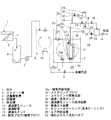
図1は本発明の濾過膜モジュール洗浄装置を備えた膜分離活性汚泥法(MBR)による下水処理システムのフロー図である。この下水処理システムにおいて、下排水や産業排水等の原水1は、スクリーン槽2に導入されて細目スクリーン3によりゴミ等を除去した状態で流量調整槽4に送られ、流量調整槽4からはポンプ5で流量調整されて脱窒槽6に送られ、脱窒槽6からは水位差による自然流下よって反応槽7に送られる。また、返送ポンプ8により反応槽7から脱窒槽6へ返送され、活性汚泥は脱窒槽6と反応槽7の間を循環するとともに、一部が反応槽7から汚泥引抜弁9により余剰汚泥として引き抜かれる。 FIG. 1 is a flow diagram of a sewage treatment system using a membrane separation activated sludge method (MBR) equipped with a filtration membrane module cleaning device of the present invention. In this sewage treatment system, raw water 1 such as sewage and industrial effluent is introduced into a
脱窒槽6においては無酸素で攪拌機10により攪拌を行なう。また、反応槽7においては、流入水(以下、被濾過水)を活性汚泥により生物処理し、反応槽7内に配置した濾過膜モジュール11で濾過し、濾過した水(以下、濾過水)を濾過配管12で濾過水タンク13に送水し、濾過水タンク13に一時貯留した後にポンプ14により濾過水タンク13から排出する。 In the
濾過膜モジュール11には、ポリフッ化ビニリデン(PVDF)等の円筒形中空糸膜モジュールが用いられている。濾過膜モジュール11は反応槽内液を透過させることにより濾過する。濾過膜モジュール11は、反応槽7内に1個または複数個配置されている。 The
反応槽7においては、散気ブロワ(曝気ブロワ)15により溶存酸素の存在下で好気処理が行われているとともに、スクラビングブロワ16およびスクラビング用散気器17によって濾過膜モジュール11を常時振動させて活性汚泥による濾過膜モジュール11の閉塞を防止している。15aは曝気用散気器である。 In the
濾過配管12の途中には濾過/逆洗ポンプ18が設けられている。該濾過/逆洗ポンプ18は、被濾過水を濾過する際、また、設定時間ごとに濾過水タンク13の濾過水を濾過膜モジュール11に供給して濾過膜モジュール11を逆洗洗浄する際、および後に説明する薬液注入装置26により濾過膜モジュール11を薬液で洗浄した後に薬液を洗い流す際に使用される。 A filtration /
濾過配管12には濾過/逆洗ポンプ18を挟んでその上流側(反応槽7側)と下流側(濾過水タンク13側)に各々第1,第2のバルブ19,20が設けられている。また、濾過配管12には第1のバルブ19の上流側と、濾過/逆洗ポンプ18と第2のバルブ20の間を繋ぐ第1の濾過水逆流路21が設けられている。第1の濾過水逆流路21には第3のバルブ22が設けられている。また、濾過配管12には濾過/逆洗ポンプ18と第1のバルブ19の間と、濾過水タンク13を繋ぐ第2の濾過水逆流路23が設けられ、該第2の濾過水逆流路23には第4のバルブ24が設けられている。 The
濾過膜モジュール11は、次に説明する濾過膜モジュール洗浄装置25によって洗浄される。 The
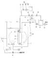
図1および図2に示すように、濾過膜モジュール洗浄装置25は、モジュール洗浄時に次亜塩素酸ナトリウム溶液等の洗浄用の薬液を濾過膜モジュール11の2次側に注入する薬液注入装置26と、濾過膜モジュール11を収容して該濾過膜モジュール11を気中に曝すためのエアを貯留可能なモジュールケーシング(洗浄ケーシング)27と、該モジュールケーシング27内にエアを供給するエア供給装置28と、からなっている。 As shown in FIGS. 1 and 2, the filtration membrane
エア供給装置28には、スクラビングブロワ16が兼用されていて、スクラビング用散気器17をモジュールケーシング27の底部に位置させることによりモジュールケーシング27の底部の開口からエアをモジュールケーシング27内に供給するようになっている。 The
薬液注入装置26は、次亜塩素酸ナトリウム溶液等の洗浄用の薬液を収容した薬液タンク29と、薬液供給ポンプ30と、薬液タンク29の薬液を濾過膜モジュール11に供給する薬液供給路31と、該薬液供給路31に設けられた第5のバルブ32と、を備えている。薬液供給路31は、第1の濾過水逆流路21よりも上流側(濾過膜モジュール11側)に接続されている。 The chemical
モジュールケーシング27は、上記薬液に侵蝕され難く、気密性を有する金属等の素材により形成されている。 The
モジュールケーシング27は、濾過膜モジュール11の直径よりも大径で、且つ濾過膜モジュール11の長さよりも長い円筒状に形成されていて、濾過膜モジュール11を1個または複数個収納している。 The
また、モジュールケーシング27の上部には液およびエア流出バルブ33が設けられている。 In addition, a liquid and
モジュールケーシング27の底部は開口しているとともに、上部は蓋板で閉塞されている。そして、薬液洗浄の際に液およびエア流出バルブ33を閉じ、上記開口からエア供給装置28でエアを供給すると、該エアは、モジュールケーシング27内の活性汚泥(被濾過水)を排除しながらモジュールケーシング27内に溜まっていって、モジュールケーシング27内に収容されている濾過膜モジュール11の周囲をエアで覆う。 The bottom of the
一方、液およびエア流出バルブ33は、これを開くことにより、モジュールケーシング27内からエアを排出してモジュールケーシング27内に活性汚泥を侵入可能にするとともに、モジュールケーシング27内に活性汚泥が満たされた後は、モジュールケーシング27の内部と外部の間の活性汚泥の循環性を確保する。液およびエア流出バルブ33には圧力エア駆動バルブを使用するのが望ましい。液およびエア流出バルブ33は1個に限らず複数個設けることによりモジュールケーシング27内のエアの排出の迅速性と、モジュールケーシング27の内部と外部の活性汚泥の循環性を向上させることができる。 On the other hand, the liquid and
液およびエア流出バルブ33を設ける位置は必ずしもモジュールケーシング27の上部の蓋板でなくてもよいが、モジュールケーシング27内に溜まったエアに濾過膜モジュール11が露出しない状態まで排出することのできる位置がよい。 The position at which the liquid and
次に、上記濾過膜モジュール洗浄装置の作用を説明する。濾過時においては、薬液注入装置26の第5のバルブ32を閉じ、液およびエア流出バルブ33を開くとともに、濾過配管12に設けた第1,第2のバルブ19,20を開いて、濾過/逆洗ポンプ18を駆動させると、反応槽7の被濾過水は、濾過膜モジュール11で濾過され濾過水となって濾過水タンク13に送水され、一時的に貯留される。 Next, the operation of the filtration membrane module cleaning device will be described. At the time of filtration, the
濾過膜モジュール11をオンエア洗浄する場合には、散気ブロワ15を停止し、さらに濾過/逆洗ポンプ18を停止し、第1,第2のバルブ19,20を閉じるとともに、液およびエア流出バルブ33を閉じる。そして、スクラビングブロワ16を駆動すると、該スクラビングブロワ16から送り出されたエアは、スクラビング用散気器17を介してモジュールケーシング27の底部に設けた開口からモジュールケーシング27内に侵入して、モジュールケーシング27内の活性汚泥を排除しながら、モジュールケーシング27内に溜まっていく。 When the
モジュールケーシング27内がエアで満たされ、該モジュールケーシング27内に収容されている濾過膜モジュール11の周囲がエアで覆われた状態になったら、スクラビングブロワ16を停止してエアの供給を停止する。 When the inside of the
スクラビングブロワ16の停止時間が遅れると供給されたエアは、所謂オーバーフロー状態になってモジュールケーシング27の底部からモジュールケーシング27の外部に漏れ出すが、多少漏れ出したとしても、処理性能や他の運転に対する影響はないので、スクラビングブロワ16によるエア供給の停止のタイミングは、厳密に制御しなくても簡易なタイマの設定で十分である。 If the stop time of the scrubbing
そして、モジュールケーシング27内をエアで満たし、濾過膜モジュール11をエアに曝した状態にしたら、第5のバルブ32を開き、薬液供給ポンプ30を駆動し、薬液タンク29の薬液を、所定量、所定時間を掛けて、濾過膜モジュール11に注入して、薬液による濾過膜モジュール11の洗浄を行う。 Then, when the inside of the
薬液による洗浄を終了したら、薬液供給ポンプ30を停止し、第5のバルブ32を閉じるとともに、第1,第2のバルブ19,20を閉じたまま、第3,第4のバルブ22,24を開き、濾過/逆洗ポンプ18を再び駆動して、濾過水タンク13の濾過水を第2の濾過水逆流路23及び第1の濾過水逆流路21を介して濾過膜モジュール11に供給し、濾過膜モジュール11を濾過水で洗浄することにより、濾過膜モジュール11の膜面等に残った薬液を洗い流して濾過膜モジュール11の洗浄を終了する。薬液の洗い流し工程は、モジュールケーシング27内の活性汚泥を満たした後に行なってもよい。 When the cleaning with the chemical liquid is completed, the chemical
濾過膜モジュール11の洗浄を終了したら、液およびエア流出バルブ33を開ける。液およびエア流出バルブ33を開けると、モジュールケーシング27内のエアは、液およびエア流出バルブ33を通って、モジュールケーシング27外に排出されるとともに、モジュールケーシング27内には活性汚泥が侵入し、モジュールケーシング27内は活性汚泥で満たされた状態になる。そこで、再度、第1,第2のバルブ19,20を開いて、散気ブロワ15、濾過/逆洗ポンプ18、スクラビングブロワ17等を駆動して濾過を再開する。濾過運転に戻るタイミングもタイマ設定で十分である。 When cleaning of the
実施例の濾過膜モジュール洗浄装置は、上述のような構成であって次に述べるような効果がある。
(1)濾過膜モジュールをモジュールケーシング内に収容してエアを供給するという簡単な方法で、濾過膜モジュールを反応槽に浸漬したままの状態でオンエア洗浄を行なうことが可能になり、従来の反応槽から活性汚泥を排出し、或いは反応槽から濾過膜モジュールを抜き出してオンエア洗浄を行なう方法に較べて、濾過膜モジュールのオンエア洗浄を容易に行なうことができる。
(2)濾過膜モジュールを気中に抜き出すことなく、濾過膜モジュールを個別にオンエア洗浄することができる。従来の反応槽から活性汚泥を排出してオンエア洗浄を行なう場合で、且つ反応槽に複数の濾過膜モジュールが設置されている場合には、設置されている全ての濾過膜モジュールの使用が出来なくなり、全体の処理能力が大きく低下するが、本発明の場合は、個別に(モジュールケーシング毎に)濾過膜モジュールのオンエア洗浄することができるので、洗浄している濾過膜モジュールを除いた他の濾過膜モジュールの使用が可能であり、安定した濾過処理量を確保することができる。
(3)濾過膜モジュールを反応槽に浸漬したままの状態で薬液洗浄できるので、濾過膜モジュール洗浄装置を容易に下水処理システムの自動運転に組み込むことができる。従って、薬液洗浄頻度を多く設定でき、濾過膜モジュールの目詰まりを抑制し、安定した処理能力を確保することができる。
(4)本発明の濾過膜モジュール洗浄装置において、特別に付加する部品は、濾過膜モジュールを収容するモジュールケーシング、該モジュールケーシングに取り付けられる液およびエア流出バルブ、バルブ用エア源程度であり、比較的安価に製造することができる。特に、モジュールケーシングにエアを供給するエア供給装置にスクラビングブロワを使用すれば、その分、部品点数を少なくしてコストを低減することができる。従って、従来のオンエア洗浄装置に較べて、はるかに安価に製作することができ、また、使用するエネルギーも少なくてすむ。The filtration membrane module cleaning device of the embodiment has the above-described configuration and has the following effects.
(1) With a simple method of storing the filtration membrane module in the module casing and supplying air, it becomes possible to perform on-air cleaning while the filtration membrane module is immersed in the reaction tank. Compared with the method of discharging activated sludge from the tank or extracting the filtration membrane module from the reaction tank and performing on-air cleaning, the on-air cleaning of the filtration membrane module can be performed easily.
(2) The filtration membrane module can be individually washed on-air without removing the filtration membrane module in the air. When activated sludge is discharged from a conventional reaction tank and on-air cleaning is performed, and when multiple filtration membrane modules are installed in the reaction tank, all the installed filtration membrane modules cannot be used. In the case of the present invention, the filtration membrane module can be individually washed on-air (for each module casing), so other filtration membranes except for the membrane membrane being washed are removed. A membrane module can be used, and a stable amount of filtration can be ensured.
(3) Since the chemical membrane cleaning can be performed while the filtration membrane module is immersed in the reaction vessel, the filtration membrane module cleaning device can be easily incorporated into the automatic operation of the sewage treatment system. Accordingly, the chemical cleaning frequency can be set high, clogging of the filtration membrane module can be suppressed, and stable processing capability can be ensured.
(4) In the filtration membrane module cleaning device of the present invention, the specially added parts are a module casing for housing the filtration membrane module, a liquid and air outflow valve attached to the module casing, and an air source for valves. Can be manufactured inexpensively. In particular, if a scrubbing blower is used in an air supply device that supplies air to the module casing, the number of parts can be reduced and the cost can be reduced accordingly. Therefore, it can be manufactured at a much lower cost than the conventional on-air cleaning apparatus, and less energy is used.
なお、上記実施例においては、エア供給装置28に、スクラビングブロワ16とスクラビング用散気器17を使用し、該スクラビング用散気器17をモジュールケーシング27の底部の開口に臨んで配置することによりエアをモジュールケーシング27内に供給する場合を示したが、エアは必ずしもモジュールケーシング27の底部の開口から供給する必要は無く、例えば、スクラビングブロワ16とスクラビング用散気器17を繋ぐエア供給路34に切換弁(図示省略)を介して分岐路(図示省略)を接続し、該分岐路の先端をモジュールケーシング27に接続して、モジュールケーシング27内にエアを供給する構成にしてもよい。分岐路からエアを供給する場合には切換弁でスクラビング用散気器17へのエアの供給を停止する。分岐路の先端には逆止弁(図示省略)を設ける。上記分岐路の先端をモジュールケーシング27に接続する位置は問わない。また、スクラビングブロワ16の代わりに散気ブロワ15を使用してモジュールケーシング27内にエアを供給する構成にしてもよい。 In the above embodiment, the scrubbing
さらに、上記スクラビングブロワ16や散気ブロワ15を使用せずに専用のエア供給ブロワを使用しても良い。また、実施例では、モジュールケーシング27を有蓋円筒状に形成した場合を示したが、モジュールケーシング27の形状は、有蓋円筒状に限定されるものではなく、濾過膜モジュール11の形状に対応させるなどして適宜の形状に形成される。また、実施例では、1個の濾過/逆洗ポンプ18で濾過を逆洗の両方を行なう構成にしたが、濾過と逆洗をそれぞれ別個のポンプで行なってもよい。また、実施例では、濾過膜モジュール11に、ポリフッ化ビニリデン(PVDF)等の円筒形中空糸膜モジュールを使用した場合を示したが、濾過膜モジュール11の材質は有機膜、無機膜を問わない。また、濾過膜モジュール11の構造も平膜、中空糸膜、単管膜等を問わない。また、上記実施例においては、専ら濾過膜モジュール洗浄装置について説明したが、この説明の中には、反応槽に浸漬して配置した濾過膜モジュールの2次側から次亜塩素酸ナトリウム溶液等の薬液を注入して、該薬液を濾過膜モジュールの1次側に浸透させて濾過膜モジュールを洗浄する濾過膜モジュール洗浄方法において、上記濾過膜モジュールをモジュールケーシングに収容し、該モジュールケーシング内にエアを導入し、上記濾過膜モジュールを気中に曝した状態で上記濾過膜モジュールの2次側に上記薬液を注入して、該薬液を上記濾過膜モジュールの1次側に浸透させるという本発明の濾過膜モジュール洗浄方法が開示されています。また、上記実施例では、本発明の濾過膜モジュール洗浄方法および濾過膜モジュール洗浄装置を下排水や産業排水中の汚濁物質等を生物処理で処理し、濾過膜モジュールで濾過する膜分離処理システムに使用した場合を説明したが、凝集剤を添加して、汚濁物質等を凝集沈殿処理し、濾過膜モジュールで濾過する膜分離処理システムに使用することもできる。 Further, a dedicated air supply blower may be used without using the
本発明は、浸漬膜に限らずケーシング収納型の膜モジュールにも応用できる。 The present invention can be applied not only to a submerged membrane but also to a casing housing type membrane module.
1…原水
2…スクリーン槽
3…荒目スクリーン
4…流量調整層
6…脱窒槽
7…反応槽
8…返送ポンプ
9…汚泥引抜弁
10…攪拌機
11…濾過膜モジュール
12…濾過配管
13…濾過水タンク
15…散気ブロワ(曝気ブロワ)
15a…曝気用散気器
16…スクラビングブロワ
17…スクラビング用散気器
18…濾過/逆洗ポンプ
19…第1のバルブ
20…第2のバルブ
21…第1の濾過水逆洗路
22…第3のバルブ
23…第1の濾過水逆洗路
24…第4のバルブ
25…濾過膜モジュール洗浄装置
26…薬液注入装置
27…モジュールケーシング(洗浄ケーシング)
28…エア供給装置
29…薬液タンク
30…薬液供給ポンプ
31…薬液供給路
32…第5のバルブ
33…液およびエア流出バルブ
34…エア供給路DESCRIPTION OF SYMBOLS 1 ...
15a ...
DESCRIPTION OF
Claims (5)
Translated fromJapanese上記濾過膜モジュールを、底部が開口し、上部が蓋板で閉塞され、該蓋板に液およびエア流出バルブを備えた洗浄用のモジュールケーシングに収容し、上記開口の下方で、かつ上記モジュールケーシング外に配置したエア供給装置からエアを上記モジュールケーシング内に供給し、上記濾過膜モジュールを気中に曝した状態で上記濾過膜モジュールの2次側から上記薬液を注入して、該薬液を上記濾過膜モジュールの1次側に浸透させることを特徴とする濾過膜モジュール洗浄方法。A filtration membrane module cleaning method for injecting a chemical solution for cleaning from the secondary side of a filtration membrane module placed in a reaction tank and allowing the chemical solution to permeate the primary side of the filtration membrane module to wash the filtration membrane module In
The filtration membrane module is accommodated ina cleaning module casing havinga bottom portion opened and a top portion closed by a lid plate, and a liquid and air outflow valve provided on the lid plate, and below the opening and the module casing. Air is supplied into the module casingfrom an air supply device arranged outside, and the chemical solution is injected from the secondary side of the filtration membrane module in a state where the filtration membrane module is exposed to the air. A filtration membrane module cleaning method, wherein the filtration membrane module is infiltrated into a primary side of the filtration membrane module.
上記濾過膜モジュールを収容し、かつ該濾過膜モジュールを気中に曝すためのエアを貯留可能な洗浄用のモジュールケーシングと、該モジュールケーシング内にエアを供給して上記濾過膜モジュールを気中に曝すエア供給装置と、を備え、
上記モジュールケーシングは、上記エア供給装置から供給されたエアをモジュールケーシング内に導入する開口を底部に備え、
上記エア供給装置は、上記開口の下方の上記モジュールケーシング外に配置されていることを特徴とする濾過膜モジュール洗浄装置。It is equipped with a chemical injection device that injects a chemical solution for cleaning on the secondary side of the filtration membrane module that is immersed in the reaction tank. In the filtration membrane module cleaning device to
A cleaning module casing capable of storing the filtration membrane module and storing air for exposing the filtration membrane module to the air, and supplying the air into the module casing to bring the filtration membrane module into the air. An air supply device to be exposed,
The module casing includes an opening at the bottom for introducing the air supplied from the air supply device into the module casing.
The filtration membrane module cleaning device, wherein the air supply device is disposed outside the module casing below the opening .
Priority Applications (5)
| Application Number | Priority Date | Filing Date | Title |
|---|---|---|---|
| JP2009159188AJP5423184B2 (en) | 2009-07-03 | 2009-07-03 | Filtration membrane module cleaning method and cleaning apparatus |
| SG2011091964ASG176812A1 (en) | 2009-07-03 | 2010-06-09 | Filtration membrane module cleaning method and cleaning device |
| PCT/JP2010/059779WO2011001803A1 (en) | 2009-07-03 | 2010-06-09 | Filtration membrane module cleaning method and cleaning device |
| CN201080029200.XACN102470325B (en) | 2009-07-03 | 2010-06-09 | Filter membrane module cleaning method and cleaning apparatus |
| KR1020127000535AKR101415678B1 (en) | 2009-07-03 | 2010-06-09 | Membrane separation activated sewage treatment method and treatment device |
Applications Claiming Priority (1)
| Application Number | Priority Date | Filing Date | Title |
|---|---|---|---|
| JP2009159188AJP5423184B2 (en) | 2009-07-03 | 2009-07-03 | Filtration membrane module cleaning method and cleaning apparatus |
Publications (2)
| Publication Number | Publication Date |
|---|---|
| JP2011011173A JP2011011173A (en) | 2011-01-20 |
| JP5423184B2true JP5423184B2 (en) | 2014-02-19 |
Family
ID=43410883
Family Applications (1)
| Application Number | Title | Priority Date | Filing Date |
|---|---|---|---|
| JP2009159188AExpired - Fee RelatedJP5423184B2 (en) | 2009-07-03 | 2009-07-03 | Filtration membrane module cleaning method and cleaning apparatus |
Country Status (5)
| Country | Link |
|---|---|
| JP (1) | JP5423184B2 (en) |
| KR (1) | KR101415678B1 (en) |
| CN (1) | CN102470325B (en) |
| SG (1) | SG176812A1 (en) |
| WO (1) | WO2011001803A1 (en) |
Cited By (2)
| Publication number | Priority date | Publication date | Assignee | Title |
|---|---|---|---|---|
| US9333464B1 (en) | 2014-10-22 | 2016-05-10 | Koch Membrane Systems, Inc. | Membrane module system with bundle enclosures and pulsed aeration and method of operation |
| USD779631S1 (en) | 2015-08-10 | 2017-02-21 | Koch Membrane Systems, Inc. | Gasification device |
Families Citing this family (1)
| Publication number | Priority date | Publication date | Assignee | Title |
|---|---|---|---|---|
| CN102107118B (en)* | 2011-01-12 | 2013-02-27 | 杭州英普水处理技术有限公司 | Reverse osmosis safety filter with cleaning function and cleaning method thereof |
Family Cites Families (12)
| Publication number | Priority date | Publication date | Assignee | Title |
|---|---|---|---|---|
| JPH0683838B2 (en)* | 1990-08-27 | 1994-10-26 | 荏原インフイルコ株式会社 | Organic wastewater biological treatment equipment |
| JPH04126528A (en)* | 1990-09-17 | 1992-04-27 | Ebara Infilco Co Ltd | Method for cleaning hollow-fiber membrane filter device the same |
| JP3178977B2 (en)* | 1994-09-29 | 2001-06-25 | 株式会社クボタ | Cleaning method of membrane element |
| JP3290556B2 (en)* | 1995-04-13 | 2002-06-10 | 株式会社クボタ | Cleaning method for immersion type membrane cartridge |
| JPH0957075A (en)* | 1995-08-29 | 1997-03-04 | Mitsubishi Heavy Ind Ltd | Membrane separation device |
| JP2002253935A (en)* | 2001-03-02 | 2002-09-10 | Togami Electric Mfg Co Ltd | Water treating device and method for preventing clogging of separation membrane used in water treating device |
| JP4360057B2 (en) | 2001-08-06 | 2009-11-11 | 株式会社ジーエス・ユアサコーポレーション | Immersion membrane filtration apparatus and immersion membrane filtration method |
| JP2004057883A (en)* | 2002-07-26 | 2004-02-26 | Mitsubishi Heavy Ind Ltd | Water cleaning method using external pressure type hollow fiber membrane module and apparatus therefor |
| JP4374260B2 (en)* | 2004-03-05 | 2009-12-02 | 前澤工業株式会社 | Immersion membrane filtration device |
| FR2894843B1 (en)* | 2005-12-20 | 2008-02-22 | Degremont Sa | METHOD AND APPARATUS FOR INTEGRITY TESTING OF FILTRATION MEMBRANES |
| JP5268349B2 (en)* | 2007-12-27 | 2013-08-21 | 株式会社東芝 | Water treatment system |
| JP2009247936A (en)* | 2008-04-02 | 2009-10-29 | Japan Organo Co Ltd | Method of inline-cleaning immersion type membrane-separation device |
- 2009
- 2009-07-03JPJP2009159188Apatent/JP5423184B2/ennot_activeExpired - Fee Related
- 2010
- 2010-06-09WOPCT/JP2010/059779patent/WO2011001803A1/enactiveApplication Filing
- 2010-06-09CNCN201080029200.XApatent/CN102470325B/ennot_activeExpired - Fee Related
- 2010-06-09KRKR1020127000535Apatent/KR101415678B1/ennot_activeExpired - Fee Related
- 2010-06-09SGSG2011091964Apatent/SG176812A1/enunknown
Cited By (5)
| Publication number | Priority date | Publication date | Assignee | Title |
|---|---|---|---|---|
| US9333464B1 (en) | 2014-10-22 | 2016-05-10 | Koch Membrane Systems, Inc. | Membrane module system with bundle enclosures and pulsed aeration and method of operation |
| US9956530B2 (en) | 2014-10-22 | 2018-05-01 | Koch Membrane Systems, Inc. | Membrane module system with bundle enclosures and pulsed aeration and method of operation |
| US10702831B2 (en) | 2014-10-22 | 2020-07-07 | Koch Separation Solutions, Inc. | Membrane module system with bundle enclosures and pulsed aeration and method of operation |
| USD779631S1 (en) | 2015-08-10 | 2017-02-21 | Koch Membrane Systems, Inc. | Gasification device |
| USD779632S1 (en) | 2015-08-10 | 2017-02-21 | Koch Membrane Systems, Inc. | Bundle body |
Also Published As
| Publication number | Publication date |
|---|---|
| SG176812A1 (en) | 2012-01-30 |
| WO2011001803A1 (en) | 2011-01-06 |
| JP2011011173A (en) | 2011-01-20 |
| KR20120027492A (en) | 2012-03-21 |
| KR101415678B1 (en) | 2014-08-05 |
| CN102470325B (en) | 2015-06-24 |
| CN102470325A (en) | 2012-05-23 |
Similar Documents
| Publication | Publication Date | Title |
|---|---|---|
| JP4920990B2 (en) | Separation membrane cleaning method | |
| US6303035B1 (en) | Immersed membrane filtration process | |
| KR101115173B1 (en) | Backwash | |
| US20060065596A1 (en) | Membrane filter cleansing process | |
| JP5453711B2 (en) | Cleaning method for external pressure hollow fiber membrane module | |
| CA2425167A1 (en) | System and method for withdrawing permeate through a filter and for cleaning the filter in situ | |
| KR101010858B1 (en) | Separator cleaning device and membrane module cleaning method using the same | |
| JP5599189B2 (en) | Apparatus for treatment of incoming fluid with bioreactor and membrane filtration module | |
| JP5467793B2 (en) | Operation method of submerged membrane separator | |
| JPH0665371B2 (en) | Organic wastewater biological treatment equipment | |
| JP3494744B2 (en) | Chemical solution cleaning method for membrane in immersion type membrane filtration device and chemical solution cleaning device | |
| JP5181987B2 (en) | Cleaning method for submerged membrane module | |
| JP5423184B2 (en) | Filtration membrane module cleaning method and cleaning apparatus | |
| JP2009247936A (en) | Method of inline-cleaning immersion type membrane-separation device | |
| KR20140128841A (en) | Apparatus for Cross cleaning water of membrane module and the operating method thereof | |
| JP2014008439A (en) | Membrane separation type water treatment apparatus and method for cleaning water treatment separation membrane | |
| JP2012045488A (en) | Water treatment apparatus and method for operation thereof | |
| JP2014172014A (en) | Membrane separation device and membrane separation method | |
| JP2007209949A (en) | Filtrate recovery device for solid-liquid mixed processing liquid | |
| JP4046445B2 (en) | Wastewater treatment method | |
| JP5251472B2 (en) | Membrane module cleaning method | |
| JP7705754B2 (en) | Wastewater treatment device and method for cleaning the same | |
| JP2000210540A (en) | Membrane filter apparatus | |
| KR100565459B1 (en) | Immersion type membrane filtration system using biofilm | |
| JP3606449B2 (en) | Filter body washing method and apparatus |
Legal Events
| Date | Code | Title | Description |
|---|---|---|---|
| A621 | Written request for application examination | Free format text:JAPANESE INTERMEDIATE CODE: A621 Effective date:20120523 | |
| A131 | Notification of reasons for refusal | Free format text:JAPANESE INTERMEDIATE CODE: A131 Effective date:20130813 | |
| A521 | Request for written amendment filed | Free format text:JAPANESE INTERMEDIATE CODE: A523 Effective date:20131003 | |
| RD02 | Notification of acceptance of power of attorney | Free format text:JAPANESE INTERMEDIATE CODE: A7422 Effective date:20131003 | |
| TRDD | Decision of grant or rejection written | ||
| A01 | Written decision to grant a patent or to grant a registration (utility model) | Free format text:JAPANESE INTERMEDIATE CODE: A01 Effective date:20131029 | |
| A61 | First payment of annual fees (during grant procedure) | Free format text:JAPANESE INTERMEDIATE CODE: A61 Effective date:20131111 | |
| R150 | Certificate of patent or registration of utility model | Free format text:JAPANESE INTERMEDIATE CODE: R150 Ref document number:5423184 Country of ref document:JP Free format text:JAPANESE INTERMEDIATE CODE: R150 | |
| LAPS | Cancellation because of no payment of annual fees |