JP5420569B2 - Method for producing a composite structure having a stable oxide binding layer - Google Patents
Method for producing a composite structure having a stable oxide binding layerDownload PDFInfo
- Publication number
- JP5420569B2 JP5420569B2JP2010543408AJP2010543408AJP5420569B2JP 5420569 B2JP5420569 B2JP 5420569B2JP 2010543408 AJP2010543408 AJP 2010543408AJP 2010543408 AJP2010543408 AJP 2010543408AJP 5420569 B2JP5420569 B2JP 5420569B2
- Authority
- JP
- Japan
- Prior art keywords
- layer
- thin film
- oxide
- bonding
- thickness
- Prior art date
- Legal status (The legal status is an assumption and is not a legal conclusion. Google has not performed a legal analysis and makes no representation as to the accuracy of the status listed.)
- Active
Links
- 239000002131composite materialSubstances0.000titleclaimsabstractdescription49
- 238000004519manufacturing processMethods0.000titleclaimsdescription40
- 239000000758substrateSubstances0.000claimsabstractdescription94
- 239000010409thin filmSubstances0.000claimsabstractdescription68
- 238000004518low pressure chemical vapour depositionMethods0.000claimsabstractdescription28
- 238000000034methodMethods0.000claimsabstractdescription25
- 239000000463materialSubstances0.000claimsdescription45
- 229910052594sapphireInorganic materials0.000claimsdescription24
- 239000010980sapphireSubstances0.000claimsdescription24
- BLRPTPMANUNPDV-UHFFFAOYSA-NSilaneChemical compound[SiH4]BLRPTPMANUNPDV-UHFFFAOYSA-N0.000claimsdescription17
- 238000000137annealingMethods0.000claimsdescription17
- 238000000151depositionMethods0.000claimsdescription17
- 239000004065semiconductorSubstances0.000claimsdescription17
- 229910000077silaneInorganic materials0.000claimsdescription17
- 238000010438heat treatmentMethods0.000claimsdescription14
- 230000008569processEffects0.000claimsdescription14
- 230000008021depositionEffects0.000claimsdescription11
- MROCJMGDEKINLD-UHFFFAOYSA-NdichlorosilaneChemical compoundCl[SiH2]ClMROCJMGDEKINLD-UHFFFAOYSA-N0.000claimsdescription11
- 229910052710siliconInorganic materials0.000claimsdescription7
- 239000010703siliconSubstances0.000claimsdescription7
- -1LiTaO 3Inorganic materials0.000claimsdescription6
- 239000002243precursorSubstances0.000claimsdescription6
- BOTDANWDWHJENH-UHFFFAOYSA-NTetraethyl orthosilicateChemical compoundCCO[Si](OCC)(OCC)OCCBOTDANWDWHJENH-UHFFFAOYSA-N0.000claimsdescription3
- 230000001186cumulative effectEffects0.000claimsdescription3
- 150000002500ionsChemical class0.000claimsdescription3
- 230000006641stabilisationEffects0.000claimsdescription3
- 238000011105stabilizationMethods0.000claimsdescription3
- 229910013641LiNbO 3Inorganic materials0.000claims2
- XUIMIQQOPSSXEZ-UHFFFAOYSA-NSiliconChemical compound[Si]XUIMIQQOPSSXEZ-UHFFFAOYSA-N0.000claims1
- 230000015572biosynthetic processEffects0.000abstractdescription14
- 239000010410layerSubstances0.000description115
- 238000000407epitaxyMethods0.000description23
- 229910052814silicon oxideInorganic materials0.000description16
- 239000010408filmSubstances0.000description12
- VYPSYNLAJGMNEJ-UHFFFAOYSA-NSilicium dioxideChemical compoundO=[Si]=OVYPSYNLAJGMNEJ-UHFFFAOYSA-N0.000description11
- 238000000623plasma-assisted chemical vapour depositionMethods0.000description9
- 238000005498polishingMethods0.000description8
- 230000032798delaminationEffects0.000description7
- 238000002513implantationMethods0.000description7
- JMASRVWKEDWRBT-UHFFFAOYSA-NGallium nitrideChemical compound[Ga]#NJMASRVWKEDWRBT-UHFFFAOYSA-N0.000description6
- 229910002601GaNInorganic materials0.000description5
- 229910004298SiO 2Inorganic materials0.000description5
- 239000013078crystalSubstances0.000description5
- 238000002347injectionMethods0.000description5
- 239000007924injectionSubstances0.000description5
- 238000000926separation methodMethods0.000description5
- 230000000087stabilizing effectEffects0.000description5
- 230000007704transitionEffects0.000description5
- 229910002704AlGaNInorganic materials0.000description4
- XKRFYHLGVUSROY-UHFFFAOYSA-NArgonChemical compound[Ar]XKRFYHLGVUSROY-UHFFFAOYSA-N0.000description4
- 238000012545processingMethods0.000description4
- 239000011241protective layerSubstances0.000description4
- 239000000126substanceSubstances0.000description4
- IJGRMHOSHXDMSA-UHFFFAOYSA-NAtomic nitrogenChemical compoundN#NIJGRMHOSHXDMSA-UHFFFAOYSA-N0.000description3
- 239000012298atmosphereSubstances0.000description3
- 238000011161developmentMethods0.000description3
- 230000002427irreversible effectEffects0.000description3
- 230000003647oxidationEffects0.000description3
- 238000007254oxidation reactionMethods0.000description3
- WSMQKESQZFQMFW-UHFFFAOYSA-N5-methyl-pyrazole-3-carboxylic acidChemical compoundCC1=CC(C(O)=O)=NN1WSMQKESQZFQMFW-UHFFFAOYSA-N0.000description2
- 229910052786argonInorganic materials0.000description2
- 238000003486chemical etchingMethods0.000description2
- 230000008878couplingEffects0.000description2
- 238000010168coupling processMethods0.000description2
- 238000005859coupling reactionMethods0.000description2
- 238000000280densificationMethods0.000description2
- 230000005489elastic deformationEffects0.000description2
- 238000002474experimental methodMethods0.000description2
- 239000007789gasSubstances0.000description2
- 239000001307heliumSubstances0.000description2
- 229910052734heliumInorganic materials0.000description2
- SWQJXJOGLNCZEY-UHFFFAOYSA-Nhelium atomChemical compound[He]SWQJXJOGLNCZEY-UHFFFAOYSA-N0.000description2
- 239000001257hydrogenSubstances0.000description2
- 229910052739hydrogenInorganic materials0.000description2
- 238000005468ion implantationMethods0.000description2
- 239000000203mixtureSubstances0.000description2
- TWNQGVIAIRXVLR-UHFFFAOYSA-Noxo(oxoalumanyloxy)alumaneChemical compoundO=[Al]O[Al]=OTWNQGVIAIRXVLR-UHFFFAOYSA-N0.000description2
- 238000001020plasma etchingMethods0.000description2
- 238000009832plasma treatmentMethods0.000description2
- LIVNPJMFVYWSIS-UHFFFAOYSA-Nsilicon monoxideChemical class[Si-]#[O+]LIVNPJMFVYWSIS-UHFFFAOYSA-N0.000description2
- 239000000243solutionSubstances0.000description2
- 230000003746surface roughnessEffects0.000description2
- 238000012360testing methodMethods0.000description2
- 238000012546transferMethods0.000description2
- UFHFLCQGNIYNRP-UHFFFAOYSA-NHydrogenChemical compound[H][H]UFHFLCQGNIYNRP-UHFFFAOYSA-N0.000description1
- 238000005411Van der Waals forceMethods0.000description1
- 230000002378acidificating effectEffects0.000description1
- 230000009471actionEffects0.000description1
- 230000003213activating effectEffects0.000description1
- 239000000853adhesiveSubstances0.000description1
- 230000001070adhesive effectEffects0.000description1
- 239000012790adhesive layerSubstances0.000description1
- 229910045601alloyInorganic materials0.000description1
- 239000000956alloySubstances0.000description1
- QVGXLLKOCUKJST-UHFFFAOYSA-Natomic oxygenChemical compound[O]QVGXLLKOCUKJST-UHFFFAOYSA-N0.000description1
- NWAIGJYBQQYSPW-UHFFFAOYSA-NazanylidyneindiganeChemical compound[In]#NNWAIGJYBQQYSPW-UHFFFAOYSA-N0.000description1
- 230000008859changeEffects0.000description1
- 238000001311chemical methods and processMethods0.000description1
- 229910052804chromiumInorganic materials0.000description1
- 230000007547defectEffects0.000description1
- 230000006866deteriorationEffects0.000description1
- 230000000694effectsEffects0.000description1
- 238000005530etchingMethods0.000description1
- 230000003993interactionEffects0.000description1
- 238000007562laser obscuration time methodMethods0.000description1
- 238000002844meltingMethods0.000description1
- 230000008018meltingEffects0.000description1
- 229910052751metalInorganic materials0.000description1
- 239000002184metalSubstances0.000description1
- 238000004377microelectronicMethods0.000description1
- 238000002156mixingMethods0.000description1
- 229910052750molybdenumInorganic materials0.000description1
- 230000007935neutral effectEffects0.000description1
- 229910052759nickelInorganic materials0.000description1
- 229910052757nitrogenInorganic materials0.000description1
- 239000012299nitrogen atmosphereSubstances0.000description1
- 230000005693optoelectronicsEffects0.000description1
- 239000001301oxygenSubstances0.000description1
- 229910052760oxygenInorganic materials0.000description1
- 229910002059quaternary alloyInorganic materials0.000description1
- HBMJWWWQQXIZIP-UHFFFAOYSA-Nsilicon carbideChemical compound[Si+]#[C-]HBMJWWWQQXIZIP-UHFFFAOYSA-N0.000description1
- 238000005728strengtheningMethods0.000description1
- 230000001629suppressionEffects0.000description1
- 238000004381surface treatmentMethods0.000description1
- 229910002058ternary alloyInorganic materials0.000description1
- 229910052721tungstenInorganic materials0.000description1
- 229910052720vanadiumInorganic materials0.000description1
- 238000000927vapour-phase epitaxyMethods0.000description1
- 230000003313weakening effectEffects0.000description1
Images


Classifications
- B—PERFORMING OPERATIONS; TRANSPORTING
- B32—LAYERED PRODUCTS
- B32B—LAYERED PRODUCTS, i.e. PRODUCTS BUILT-UP OF STRATA OF FLAT OR NON-FLAT, e.g. CELLULAR OR HONEYCOMB, FORM
- B32B37/00—Methods or apparatus for laminating, e.g. by curing or by ultrasonic bonding
- B32B37/14—Methods or apparatus for laminating, e.g. by curing or by ultrasonic bonding characterised by the properties of the layers
- H—ELECTRICITY
- H01—ELECTRIC ELEMENTS
- H01L—SEMICONDUCTOR DEVICES NOT COVERED BY CLASS H10
- H01L21/00—Processes or apparatus adapted for the manufacture or treatment of semiconductor or solid state devices or of parts thereof
- H01L21/02—Manufacture or treatment of semiconductor devices or of parts thereof
- H01L21/02104—Forming layers
- H01L21/02107—Forming insulating materials on a substrate
- H01L21/02225—Forming insulating materials on a substrate characterised by the process for the formation of the insulating layer
- H01L21/0226—Forming insulating materials on a substrate characterised by the process for the formation of the insulating layer formation by a deposition process
- H01L21/02263—Forming insulating materials on a substrate characterised by the process for the formation of the insulating layer formation by a deposition process deposition from the gas or vapour phase
- H01L21/02271—Forming insulating materials on a substrate characterised by the process for the formation of the insulating layer formation by a deposition process deposition from the gas or vapour phase deposition by decomposition or reaction of gaseous or vapour phase compounds, i.e. chemical vapour deposition
- H—ELECTRICITY
- H01—ELECTRIC ELEMENTS
- H01L—SEMICONDUCTOR DEVICES NOT COVERED BY CLASS H10
- H01L21/00—Processes or apparatus adapted for the manufacture or treatment of semiconductor or solid state devices or of parts thereof
- H01L21/02—Manufacture or treatment of semiconductor devices or of parts thereof
- H01L21/02104—Forming layers
- H01L21/02107—Forming insulating materials on a substrate
- H01L21/02225—Forming insulating materials on a substrate characterised by the process for the formation of the insulating layer
- H01L21/0226—Forming insulating materials on a substrate characterised by the process for the formation of the insulating layer formation by a deposition process
- H01L21/02293—Forming insulating materials on a substrate characterised by the process for the formation of the insulating layer formation by a deposition process formation of epitaxial layers by a deposition process
- H—ELECTRICITY
- H01—ELECTRIC ELEMENTS
- H01L—SEMICONDUCTOR DEVICES NOT COVERED BY CLASS H10
- H01L21/00—Processes or apparatus adapted for the manufacture or treatment of semiconductor or solid state devices or of parts thereof
- H01L21/02—Manufacture or treatment of semiconductor devices or of parts thereof
- H01L21/02104—Forming layers
- H01L21/02365—Forming inorganic semiconducting materials on a substrate
- H01L21/02436—Intermediate layers between substrates and deposited layers
- H01L21/02439—Materials
- H01L21/02469—Group 12/16 materials
- H01L21/02472—Oxides
- H—ELECTRICITY
- H01—ELECTRIC ELEMENTS
- H01L—SEMICONDUCTOR DEVICES NOT COVERED BY CLASS H10
- H01L21/00—Processes or apparatus adapted for the manufacture or treatment of semiconductor or solid state devices or of parts thereof
- H01L21/02—Manufacture or treatment of semiconductor devices or of parts thereof
- H01L21/04—Manufacture or treatment of semiconductor devices or of parts thereof the devices having potential barriers, e.g. a PN junction, depletion layer or carrier concentration layer
- H01L21/18—Manufacture or treatment of semiconductor devices or of parts thereof the devices having potential barriers, e.g. a PN junction, depletion layer or carrier concentration layer the devices having semiconductor bodies comprising elements of Group IV of the Periodic Table or AIIIBV compounds with or without impurities, e.g. doping materials
- H01L21/185—Joining of semiconductor bodies for junction formation
- H—ELECTRICITY
- H01—ELECTRIC ELEMENTS
- H01L—SEMICONDUCTOR DEVICES NOT COVERED BY CLASS H10
- H01L21/00—Processes or apparatus adapted for the manufacture or treatment of semiconductor or solid state devices or of parts thereof
- H01L21/02—Manufacture or treatment of semiconductor devices or of parts thereof
- H01L21/04—Manufacture or treatment of semiconductor devices or of parts thereof the devices having potential barriers, e.g. a PN junction, depletion layer or carrier concentration layer
- H01L21/18—Manufacture or treatment of semiconductor devices or of parts thereof the devices having potential barriers, e.g. a PN junction, depletion layer or carrier concentration layer the devices having semiconductor bodies comprising elements of Group IV of the Periodic Table or AIIIBV compounds with or without impurities, e.g. doping materials
- H01L21/30—Treatment of semiconductor bodies using processes or apparatus not provided for in groups H01L21/20 - H01L21/26
- H01L21/324—Thermal treatment for modifying the properties of semiconductor bodies, e.g. annealing, sintering
- H—ELECTRICITY
- H01—ELECTRIC ELEMENTS
- H01L—SEMICONDUCTOR DEVICES NOT COVERED BY CLASS H10
- H01L21/00—Processes or apparatus adapted for the manufacture or treatment of semiconductor or solid state devices or of parts thereof
- H01L21/70—Manufacture or treatment of devices consisting of a plurality of solid state components formed in or on a common substrate or of parts thereof; Manufacture of integrated circuit devices or of parts thereof
- H01L21/71—Manufacture of specific parts of devices defined in group H01L21/70
- H01L21/76—Making of isolation regions between components
- H01L21/762—Dielectric regions, e.g. EPIC dielectric isolation, LOCOS; Trench refilling techniques, SOI technology, use of channel stoppers
- H01L21/7624—Dielectric regions, e.g. EPIC dielectric isolation, LOCOS; Trench refilling techniques, SOI technology, use of channel stoppers using semiconductor on insulator [SOI] technology
- H01L21/76251—Dielectric regions, e.g. EPIC dielectric isolation, LOCOS; Trench refilling techniques, SOI technology, use of channel stoppers using semiconductor on insulator [SOI] technology using bonding techniques
- H01L21/76254—Dielectric regions, e.g. EPIC dielectric isolation, LOCOS; Trench refilling techniques, SOI technology, use of channel stoppers using semiconductor on insulator [SOI] technology using bonding techniques with separation/delamination along an ion implanted layer, e.g. Smart-cut, Unibond
- H—ELECTRICITY
- H01—ELECTRIC ELEMENTS
- H01L—SEMICONDUCTOR DEVICES NOT COVERED BY CLASS H10
- H01L2924/00—Indexing scheme for arrangements or methods for connecting or disconnecting semiconductor or solid-state bodies as covered by H01L24/00
- H01L2924/0001—Technical content checked by a classifier
- H01L2924/0002—Not covered by any one of groups H01L24/00, H01L24/00 and H01L2224/00
- H—ELECTRICITY
- H10—SEMICONDUCTOR DEVICES; ELECTRIC SOLID-STATE DEVICES NOT OTHERWISE PROVIDED FOR
- H10H—INORGANIC LIGHT-EMITTING SEMICONDUCTOR DEVICES HAVING POTENTIAL BARRIERS
- H10H20/00—Individual inorganic light-emitting semiconductor devices having potential barriers, e.g. light-emitting diodes [LED]
- H10H20/01—Manufacture or treatment
- H10H20/011—Manufacture or treatment of bodies, e.g. forming semiconductor layers
- H10H20/018—Bonding of wafers
- Y—GENERAL TAGGING OF NEW TECHNOLOGICAL DEVELOPMENTS; GENERAL TAGGING OF CROSS-SECTIONAL TECHNOLOGIES SPANNING OVER SEVERAL SECTIONS OF THE IPC; TECHNICAL SUBJECTS COVERED BY FORMER USPC CROSS-REFERENCE ART COLLECTIONS [XRACs] AND DIGESTS
- Y10—TECHNICAL SUBJECTS COVERED BY FORMER USPC
- Y10T—TECHNICAL SUBJECTS COVERED BY FORMER US CLASSIFICATION
- Y10T156/00—Adhesive bonding and miscellaneous chemical manufacture
- Y10T156/10—Methods of surface bonding and/or assembly therefor
- Y—GENERAL TAGGING OF NEW TECHNOLOGICAL DEVELOPMENTS; GENERAL TAGGING OF CROSS-SECTIONAL TECHNOLOGIES SPANNING OVER SEVERAL SECTIONS OF THE IPC; TECHNICAL SUBJECTS COVERED BY FORMER USPC CROSS-REFERENCE ART COLLECTIONS [XRACs] AND DIGESTS
- Y10—TECHNICAL SUBJECTS COVERED BY FORMER USPC
- Y10T—TECHNICAL SUBJECTS COVERED BY FORMER US CLASSIFICATION
- Y10T428/00—Stock material or miscellaneous articles
- Y10T428/26—Web or sheet containing structurally defined element or component, the element or component having a specified physical dimension
- Y10T428/263—Coating layer not in excess of 5 mils thick or equivalent
- Y10T428/264—Up to 3 mils
- Y10T428/265—1 mil or less
Landscapes
- Engineering & Computer Science (AREA)
- Microelectronics & Electronic Packaging (AREA)
- Condensed Matter Physics & Semiconductors (AREA)
- General Physics & Mathematics (AREA)
- Manufacturing & Machinery (AREA)
- Computer Hardware Design (AREA)
- Physics & Mathematics (AREA)
- Power Engineering (AREA)
- Chemical & Material Sciences (AREA)
- Chemical Kinetics & Catalysis (AREA)
- Recrystallisation Techniques (AREA)
- Measuring Fluid Pressure (AREA)
- Ceramic Products (AREA)
- Laminated Bodies (AREA)
- Crystals, And After-Treatments Of Crystals (AREA)
Abstract
Description
Translated fromJapanese 本発明は、堆積させた酸化物結合層を介して薄膜を結合させた、少なくとも1つの支持基板を含む複合構造の製造に関する。この種の構造は、マイクロ電子工学、光電子工学および光学の分野において、III/V族などの半導体材料、特にGaN、AlGaN、InGaNまたはInAlGaNのような、2元、3元または4元のIII/N族材料を、エピタ
キシャル成長によって製造するために使用することを目的としている。The present invention relates to the manufacture of a composite structure comprising at least one support substrate having thin films bonded through a deposited oxide bonding layer. This type of structure is used in the field of microelectronics, optoelectronics and optics, semiconductor materials such as III / V, in particular binary, ternary or quaternary III / V, such as GaN, AlGaN, InGaN or InAlGaN. It is intended to be used for producing Group N materials by epitaxial growth.
この種の複合構造は、一般的には、下記の工程を備える周知のスマートカット(登録商標)法を用いて製造される。
・ソース基板、言い換えればドナー基板、にイオン注入して、基板内の所定の深さに脆弱な領域を形成する。
・注入を受けたドナー基板の面を、支持基板、別名“受容基板”に(ウェーハ接合によって)結合させる。
・脆弱な領域における剥離によってドナー基板を分離して、注入を受けた面とドナー基板の脆弱な領域との間に位置する部分を受容基板に転移させる。分離された部分は、複合構造の薄膜を構成する。This type of composite structure is generally manufactured using the well-known Smart Cut (registered trademark) method comprising the following steps.
Ion implantation into a source substrate, in other words, a donor substrate, to form a fragile region at a predetermined depth in the substrate.
The surface of the donor substrate that has undergone implantation is bonded (by wafer bonding) to a support substrate, also known as a “receiving substrate”.
-Separating the donor substrate by delamination in the fragile region and transferring the portion located between the implanted surface and the fragile region of the donor substrate to the receiving substrate. The separated portion constitutes a thin film having a composite structure.
ソース基板からの薄膜の分離を促進するためには、ソース基板と支持基板との間の良好な結合が必要である。熱膨張係数が異なる材料を有しているにも関わらず高い安定性を有する複合構造は、2つの結合層の間に形成される結合面によって可能となる。これらの結合層は、密着させるべきソース基板および支持基板の面上に形成される酸化物層に相当する。これらの酸化物層は、ウェーハ接合時に、基板の密着を促進する平坦化層として作用する。これにより、複合構造は、エピタキシャル成長のような大きな温度変化を伴う処理に、劣化することなく耐えることができる。 In order to facilitate the separation of the thin film from the source substrate, a good bond between the source substrate and the support substrate is required. A composite structure with high stability despite having materials with different coefficients of thermal expansion is made possible by the bonding surface formed between the two bonding layers. These bonding layers correspond to oxide layers formed on the surfaces of the source substrate and the support substrate to be adhered. These oxide layers act as a planarization layer that promotes adhesion of the substrate during wafer bonding. As a result, the composite structure can withstand a process involving a large temperature change such as epitaxial growth without deterioration.
エピタキシャル成長のための複合構造の製造は、ソース基板と支持基板とを結合させる工程と、その後に実施する、ソース基板を化学的に薄肉化する工程または機械的に研磨する工程とによって、薄膜を所望の厚さにすることによっても実施することができる。さらに、この態様の製造では、温度安定性の高い結合も要求されるため、良好な結合面を保証する酸化物結合層の使用が要求される。 Fabrication of a composite structure for epitaxial growth is achieved by combining a source substrate and a support substrate and then performing a thinning process on the source substrate by chemical thinning or mechanical polishing. It can also be carried out by making the thickness of this. Furthermore, the manufacture of this embodiment requires bonding with high temperature stability, and therefore requires the use of an oxide bonding layer that ensures a good bonding surface.
シリコンまたはシリコンカーバイド(SiC)から形成される材料を用いた場合、基板は、適切な雰囲気において加熱されて酸化され、“熱酸化物”と呼ばれるシリコンの酸化物結合層(SiO2)が得られる。熱酸化物は、化学量論的酸化物に相当する。熱酸化物
は、高密度(FH溶液によってゆっくりと腐食するのであれば、SiO2は高密度である
とされる)であり、高温下でも安定している。When a material formed from silicon or silicon carbide (SiC) is used, the substrate is heated and oxidized in a suitable atmosphere to obtain a silicon oxide bonding layer (SiO2 ) called “thermal oxide”. . Thermal oxides correspond to stoichiometric oxides. The thermal oxide has a high density (if it is slowly corroded by the FH solution, SiO2 is considered to be a high density) and is stable even at high temperatures.
2つの基板を結合させるときに、一方の基板が、例えばサファイアの基板のような熱酸化によってシリコンの酸化物層を形成することができない材料である場合は、プラズマ化学気相成長(PECVD)、または減圧化学気相成長(LPCVD)のような方法を用いた堆積によって、シリコンの酸化物を形成する必要がある。これは、“堆積酸化物”である。堆積酸化物は、熱酸化によって得られた化学量論的なSiO2とは異なる構成を有す
る(堆積した酸化物は、SixOyHzの組成を有する)。このような堆積酸化物は、密度
が比較的低く、熱酸化物と同様の特性を有さない。密度を高めて熱酸化物の特性に近づけるために、熱処理を実施してもよい。しかし、高密度化のためのアニール処理の後であっても、特に、酸化物の堆積温度よりも高い温度下で実施される処理の際は、堆積酸化物は
、依然として熱的に不安定であり得る。When bonding two substrates, if one substrate is a material that cannot form a silicon oxide layer by thermal oxidation, such as a sapphire substrate, plasma enhanced chemical vapor deposition (PECVD), Alternatively, silicon oxide must be formed by deposition using methods such as low pressure chemical vapor deposition (LPCVD). This is a “deposited oxide”. The deposited oxide has a different structure from the stoichiometric SiO2 obtained by thermal oxidation (the deposited oxide has a composition of Six Oy Hz ). Such deposited oxides have a relatively low density and do not have the same characteristics as thermal oxides. Heat treatment may be performed to increase the density and approximate the properties of the thermal oxide. However, even after annealing for densification, the deposited oxide is still thermally unstable, especially during processing performed at temperatures higher than the oxide deposition temperature. possible.
例えば、サファイアの薄肉層が設けられたサファイアの支持基板によって形成された複合基板が、GaNのエピタキシーのために加熱される際に、酸化物の堆積温度を超えると、マイクロキャビティが発生する。マイクロキャビティは、シリコンの堆積酸化物である結合層においてもっぱら発生する。マイクロキャビティは、非可逆に発生する気泡が形成されることによって、サファイアの薄膜の表面において可視となる。気泡は、その表面を“歪め(buckle)”、もはや平滑ではなく、格子パラメータが歪んだ状態を示すようにするため、その表面は、エピタキシーには不適となる。堆積酸化物層におけるマイクロキャビティは、温度が上昇するにつれて、より速く発生し、より速く発達する。 For example, when a composite substrate formed by a sapphire support substrate provided with a thin sapphire layer is heated for GaN epitaxy, a microcavity is generated when the oxide deposition temperature is exceeded. Microcavities occur exclusively in the bonding layer, which is a deposited oxide of silicon. The microcavity becomes visible on the surface of the sapphire thin film by forming irreversibly generated bubbles. Bubbles "buckle" the surface and are no longer smooth, making the surface unsuitable for epitaxy because the lattice parameters exhibit a distorted state. Microcavities in the deposited oxide layer occur faster and grow faster as the temperature increases.
その密度および大きさによっては、このようなマイクロキャビティは、結合層において脆弱な領域を生じさせる可能性があり、その後に構造上で処理を実施すると、薄膜の剥離をもたらし得る。このようなマイクロキャビティは、酸化物層の全体にも影響し、酸化物層の断裂の原因となり、最終的には、支持基板からの薄膜の分離の原因となり得る。このように、複合構造の製造の際とその後のエピタキシーの際のいずれにおいても、マイクロキャビティの発生は、常に薄膜の剥離をもたらす。 Depending on its density and size, such microcavities can create fragile regions in the bonding layer, and subsequent processing on the structure can result in delamination of the film. Such a microcavity also affects the entire oxide layer, causing the oxide layer to rupture, and eventually causing the separation of the thin film from the support substrate. Thus, both during the manufacture of the composite structure and during the subsequent epitaxy, the generation of microcavities always results in thin film peeling.
この問題を説明するために、出願人は下記の実験を実施した。転移させるべき薄膜の厚さが0.6μm(マイクロメートル)である脆弱な領域を含むサファイアのソース基板を、300℃でのPECVDによって堆積させて厚さ0.3μmとなった酸化物結合層を有するサファイアの支持体に結合させた。上記の目的のため、2つの基板を雰囲気温度の下で密着させて、1100℃での3時間にわたる結合の強化のためのアニール処理を実施し、その後に分割させるための熱処理を施した。そうすると、堆積酸化物層の内部での分離に起因する、転移させたサファイアの膜の完全な分離が観察された。 To illustrate this problem, Applicants conducted the following experiment. A sapphire source substrate including a fragile region whose thickness of a thin film to be transferred is 0.6 μm (micrometer) is deposited by PECVD at 300 ° C. to form an oxide bonding layer having a thickness of 0.3 μm. Bonded to a sapphire support. For the above purpose, the two substrates were brought into close contact with each other at an ambient temperature, and an annealing treatment for strengthening the bond at 1100 ° C. for 3 hours was performed, followed by a heat treatment for dividing. Then, complete separation of the transferred sapphire film due to separation inside the deposited oxide layer was observed.
特許文献EP−A−0898307には、PECVD法によって形成された酸化物結合層を用いた、結合面における支持体とウェーハとの結合の解除方法が記載されている。上記の特許文献の酸化物は、結合の安定化のためのアニール処理および集積回路上における所望の処理の後に実施される熱処理(600〜1350℃)の作用によって結合面へと拡散する、OH種を有するために特有の性質を有する。上記の種は、気体が形成されるまで発達し、その後拡散して、例えばウェーハ上に堆積された酸化物結合層と支持基板との間の境界面などの結合面に偏在する泡となる。このような現象は、当初はウェーハ上に堆積されてウェーハと一体である結合層と支持基板との結合を完全に解除するまで結合面の脆弱化を促進する。 Patent document EP-A-0898307 describes a method for releasing the bond between a support and a wafer at a bonding surface using an oxide bonding layer formed by PECVD. The oxides of the above-mentioned patent documents diffuse into the bonding surface by the action of annealing treatment for stabilizing the bond and the heat treatment (600 to 1350 ° C.) performed after the desired treatment on the integrated circuit. Because of having a characteristic characteristic. The above species develop until a gas is formed and then diffuse into bubbles that are unevenly distributed on the bonding surface, such as the interface between the oxide bonding layer deposited on the wafer and the support substrate. Such a phenomenon promotes weakening of the bonding surface until the bonding between the bonding layer, which is initially deposited on the wafer and is integral with the wafer, is completely released.
しかし、結合面における気体種および泡の集中について記載された特許文献EP−A−0898307の内容とは異なり、高圧(>100MPa(メガパスカル))下で熱処理の温度が酸化物のクリープ温度を超えると、本発明において抑制するべきマイクロキャビティは堆積酸化物層全体にわたって形成される。クリープ温度は、例えば、意図的にドーピングされていない、LPCVD法またはPECVD法で堆積されたSiO2層であれば
、約800℃から1200℃の範囲である。上記のマイクロキャビティは、転移させた薄膜の表面を変形させる効果を有し、エピタキシーのような特定の適用を阻害する。さらに、出願人によって観察された膜の剥離は、酸化物層の内部の分離に由来する。結合層は、結合面において結合の解除がされず、全体にわたって発達したマイクロキャビティによって断裂する。However, unlike the content of patent document EP-A-0898307, which describes the concentration of gas species and bubbles on the bonding surface, the temperature of the heat treatment exceeds the creep temperature of the oxide under high pressure (> 100 MPa (megapascal)). And the microcavity to be suppressed in the present invention is formed over the entire deposited oxide layer. The creep temperature is, for example, in the range of about 800 ° C. to 1200 ° C. for a SiO2 layer deposited by LPCVD or PECVD, which is not intentionally doped. The microcavities described above have the effect of deforming the surface of the transferred thin film, hindering certain applications such as epitaxy. Furthermore, the film delamination observed by the applicant comes from the separation inside the oxide layer. The bonding layer is not released from bonding at the bonding surface, but is broken by the microcavities developed throughout.
特許文献US−2006/0255341は、III/N族材料のエピタキシャル成長を
目的とし、支持基板上への種薄膜の転移による複合構造の製造について記載している。より低い熱膨張係数を有する支持基板への、サファイアの薄肉層の(酸化物層を介さない)
直接の結合には、薄肉層において折り曲げ現象(folding phenomenon)が生じる高圧を要する。サファイアの層の転移には、大量のイオン種の注入が必要であり、転移された層の厚さ方向に応力勾配が形成される。結合状態に起因して応力が大きくなると材料が変形し、これにより応力は緩和される。これを改善するために、特許文献では、層の機械的強度を向上させるために800nm(ナノメートル)オーダーの厚さを有するサファイアの層を使用している。Patent document US-2006 / 0255341 describes the manufacture of a composite structure by the transfer of a seed film onto a support substrate for the purpose of epitaxial growth of III / N materials. A thin layer of sapphire (without an oxide layer) on a support substrate with a lower coefficient of thermal expansion
Direct bonding requires a high pressure that causes a folding phenomenon in the thin layer. Transition of the sapphire layer requires implantation of a large amount of ionic species, and a stress gradient is formed in the thickness direction of the transferred layer. When the stress increases due to the bonding state, the material is deformed, and thereby the stress is relieved. In order to improve this, the patent literature uses a layer of sapphire with a thickness on the order of 800 nm (nanometers) in order to improve the mechanical strength of the layer.
この特許文献はまた、転移時における、硬質の材料であるサファイアの薄肉層の剥離現象について記載している。剥離現象の原因は、注入、材料の熱膨張係数の相違および化学的にほぼ非活性で他の材料の表面と共有結合を形成しにくいその表面に基づく応力である。これを抑制するために、表面、すなわちSiO2、Si3N4、AlNの結合層および/
または接着材の層を活性化させるためのプラズマ処理を実施してもよい。This patent document also describes a peeling phenomenon of a thin layer of sapphire, which is a hard material, at the time of transition. The cause of the debonding phenomenon is injection, a difference in thermal expansion coefficient of the material, and stress based on the surface which is almost inactive and hardly forms a covalent bond with the surface of another material. To suppress this, a surface, i.e.SiO 2, Si 3 N 4, AlN bonding layer and /
Alternatively, plasma treatment for activating the adhesive layer may be performed.
本発明は、上記の不利益を抑制することを目的とし、複合構造であって、薄膜および支持基板が、構造が配置され得る温度範囲、例えば20℃から1200℃、にわたって、7×10⁻⁶K-1またはそれよりも大きな平均熱膨張係数を有し、結合層が、高温下においても安定である少なくとも1つのシリコンの堆積酸化物層を含む、複合構造を提供する。本発明は、複合構造の製造時に施される熱処理の際に、薄膜の変形および剥離をもたらす堆積酸化物層におけるマイクロキャビティの形成および発達を避けるための複合構造の製造、およびこの複合構造から開始されるエピタキシーによる材料の形成を可能とすることを目的とする。The present invention aims to suppress the above disadvantages, and is a composite structure, in which the thin film and the supporting substrate are 7 × 10⁻⁶ over a temperature range in which the structure can be disposed, for example, 20 ° C. to 1200 ° C. A composite structure is provided having an average coefficient of thermal expansion of K−1 or greater and the bonding layer comprising at least one deposited oxide layer of silicon that is stable even at high temperatures. The present invention begins with the fabrication of a composite structure to avoid the formation and development of microcavities in the deposited oxide layer that result in deformation and delamination of the thin film during the heat treatment applied during the fabrication of the composite structure. The object is to enable the formation of materials by epitaxy.
この目的は、支持基板の結合面上および/または薄膜の結合面上において酸化物層を減圧化学気相成長(LPCVD)させて、シリコンの酸化物結合層を形成し、その薄膜の厚さを5マイクロメートルまたはそれ未満にして、かつ、シリコンの酸化物層の厚さを薄膜の厚さに等しいかまたはそれよりも大きくする複合構造の製造方法によって達成される。 The purpose is to perform low pressure chemical vapor deposition (LPCVD) of the oxide layer on the bonding surface of the support substrate and / or on the bonding surface of the thin film to form an oxide bonding layer of silicon, and to reduce the thickness of the thin film. It is achieved by a method of manufacturing a composite structure that is 5 micrometers or less and that the thickness of the silicon oxide layer is equal to or greater than the thickness of the thin film.
以下で詳細に説明するように、薄膜よりも厚い結合層をLPCVDによって形成して使用すると、結合層における塑性(非可逆)変形が抑制される。これにより、高温(特に900℃よりも高い温度)下の熱処理時においても、シリコンの堆積酸化物の結合層におけるマイクロキャビティの形成を抑制することができる。 As will be described in detail below, when a bonding layer thicker than the thin film is formed and used by LPCVD, plastic (irreversible) deformation in the bonding layer is suppressed. Thereby, even during the heat treatment at a high temperature (particularly higher than 900 ° C.), the formation of the microcavity in the bonded layer of the deposited oxide of silicon can be suppressed.
引き続いて、以下で詳細に説明するように、採用した堆積方法によるシリコンの酸化物層の温度挙動に関して、出願人は、LPCVDによって堆積させると、熱酸化によって得られるシリコンの酸化物の温度安定性に近い温度安定性を有する酸化物を生じさせ得ることを明らかにした。さらに、複合構造内の酸化物層の熱膨張係数よりも大きな熱膨張係数を有する材料の存在に由来する応力に耐えるために、酸化物層の厚さを、5マイクロメートルに制限される薄膜の厚さよりも大きいかまたはそれと等しくする。これにより、高温下の処理時において、結合層に加わる応力が抑制され得る。すなわち、結合層において塑性変形が生じる危険性が抑制され得る。 Subsequently, as will be described in detail below, with respect to the temperature behavior of the silicon oxide layer by the employed deposition method, the applicant has determined that the temperature stability of the silicon oxide obtained by thermal oxidation when deposited by LPCVD. It was clarified that an oxide having a temperature stability close to that can be produced. In addition, in order to withstand stresses due to the presence of materials having a coefficient of thermal expansion greater than that of the oxide layer in the composite structure, the thickness of the oxide layer is limited to 5 micrometers. Greater than or equal to the thickness. Thereby, the stress added to a coupling layer can be suppressed at the time of the process under high temperature. That is, the risk of plastic deformation occurring in the bonding layer can be suppressed.
減圧化学気相成長によって形成されるシリコンの酸化物結合層の材料は、シラン、ジクロシラン、またはTEOS(オルトけい酸テトラエチル)のような、別の公知の前駆体を用いて形成され得る。 The material of the silicon oxide bonding layer formed by low pressure chemical vapor deposition may be formed using another known precursor, such as silane, dichlorosilane, or TEOS (tetraethyl orthosilicate).
本発明は、その一側面から、結合の前に、支持基板の結合面上および/または薄膜の結合面上における減圧化学気相成長によって堆積されたシリコンの酸化物層を高密度化する熱処理工程をさらに含む製造方法を提供する。この高密度化する熱処理は、堆積酸化物のマイクロキャビティの形成に関する温度挙動を、さらに改善し得る。必要に応じ、この工
程により、薄膜の厚さに対する堆積酸化物層の厚さの比を小さくすることができる。In one aspect, the present invention provides a heat treatment step for densifying a silicon oxide layer deposited by low pressure chemical vapor deposition on a bonding surface of a support substrate and / or on a bonding surface of a thin film before bonding. A manufacturing method further comprising: This densifying heat treatment can further improve the temperature behavior with respect to the formation of deposited oxide microcavities. If necessary, this step can reduce the ratio of the thickness of the deposited oxide layer to the thickness of the thin film.
熱処理工程は、酸化物結合層の堆積温度よりも高い温度下で実施される。場合によっては、熱処理は、例えば中性雰囲気または酸性雰囲気中で実施され得る。 The heat treatment step is performed at a temperature higher than the deposition temperature of the oxide bonding layer. In some cases, the heat treatment can be performed, for example, in a neutral or acidic atmosphere.
本発明における特別な特徴に従えば、薄膜はスマートカット(登録商標)法を用いて得ることができる。本製造方法はさらに、
・ドナー基板の1つの面にイオンを打ち込んで注入して基板内の所定の深さに脆弱層を形成し、基板の上部に薄膜を規定する工程と、
・ドナー基板を支持基板に密着させて配置して結合させる工程と、
・ドナー基板内に形成した脆弱層における分割によって、支持基板に接する薄膜を分離する工程と、
を含む。According to a special feature of the present invention, the thin film can be obtained using the Smart Cut (registered trademark) method. The manufacturing method further includes
-Implanting and implanting ions into one surface of the donor substrate to form a fragile layer at a predetermined depth within the substrate and defining a thin film on top of the substrate;
A step in which the donor substrate is placed in close contact with the support substrate and bonded;
Separating the thin film in contact with the support substrate by dividing the weak layer formed in the donor substrate;
including.
本発明における特別な特徴に従えば、薄膜を、
・ドナー基板を支持基板に密着させて結合させる工程と、
・ドナー基板を化学的または機械的に薄肉化して薄膜を形成する工程と、
によって製造してもよい。According to special features of the present invention, the thin film
A step of bringing the donor substrate into close contact with the support substrate and bonding;
-Thinning the donor substrate chemically or mechanically to form a thin film;
May be manufactured.
結合させる工程の後に、堆積酸化物層においてマイクロキャビティを発生させることなく、約900℃よりも高い温度で結合の安定化のためのアニール処理の工程を実施してもよい。 After the bonding step, an annealing step for stabilization of bonding may be performed at a temperature higher than about 900 ° C. without generating microcavities in the deposited oxide layer.
本発明はまた、上記の製造方法により製造された複合構造上での、エピタキシャル成長による、GaN、AlGaN、InGaNまたはInAlGaNのような、特に2元、3元または4元のIII/V族およびIII/N族の少なくとも1つの半導体材料層の製造方法を
提供する。エピタキシャル成長は、成長のための種結晶層を形成する複合構造の薄膜から実施される。The present invention also relates to, particularly, binary, ternary or quaternary III / V and III / V, such as GaN, AlGaN, InGaN or InAlGaN by epitaxial growth on the composite structure produced by the above production method. A method for producing at least one semiconductor material layer of Group N is provided. Epitaxial growth is performed from a thin film of a composite structure that forms a seed crystal layer for growth.
本発明の一側面から、エピタキシャル成長は、自己支持するのに十分な厚さの、すなわち少なくとも100μmの厚さを有する半導体材料層の成長に要する期間に相当する所定の期間にわたって実施される。そうすると、エピタキシー後には、複合構造を取り除くことができる。変形例では、成長のための種結晶層は、エピタキシーにより成長した半導体材料層とともに保護されて、繰り返し実施されるエピタキシーに用いられ得る自立構造を構成する。この場合、半導体材料層のエピタキシャル成長は、製造される種層および半導体層の累積的な厚さが少なくとも100μmとなるように、所定の期間にわたって実施される。 According to one aspect of the invention, epitaxial growth is performed for a predetermined period corresponding to the period required to grow a semiconductor material layer having a thickness sufficient to be self-supporting, ie having a thickness of at least 100 μm. Then, after the epitaxy, the composite structure can be removed. In a variant, the seed crystal layer for growth is protected together with a semiconductor material layer grown by epitaxy and constitutes a free-standing structure that can be used for repeated epitaxy. In this case, the epitaxial growth of the semiconductor material layer is performed over a predetermined period so that the cumulative thickness of the seed layer and the semiconductor layer to be produced is at least 100 μm.
本発明のさらに別の側面から、エピタキシャル成長は、複合構造のいずれのアニール処理よりも前に、少なくとも10μmの厚さを有する半導体材料層の成長に要する期間に相当する所定の期間にわたって実施される。この厚さは、得られた層に手を加えなくとも、同一のエピタキシー装置内において新たに実施するエピタキシャル成長の工程の環境に十分に耐え得る厚さに相当する。種結晶層が保護されれば(支持基板のみが分離しても)、成長は、種層および半導体層の累積的な厚さが少なくとも10μmとなり得る期間にわたって実施される。 From yet another aspect of the present invention, the epitaxial growth is performed for a predetermined period corresponding to the period required for the growth of a semiconductor material layer having a thickness of at least 10 μm prior to any annealing treatment of the composite structure. This thickness corresponds to a thickness that can sufficiently withstand the environment of an epitaxial growth process newly performed in the same epitaxy apparatus without modifying the obtained layer. If the seed crystal layer is protected (even if only the support substrate is separated), the growth is carried out over a period of time where the cumulative thickness of the seed layer and the semiconductor layer can be at least 10 μm.
本発明はまた、上記のような複合構造の製造方法により製造された複合構造も提供する。 The present invention also provides a composite structure manufactured by the composite structure manufacturing method as described above.
本発明は、一般的に、少なくとも1つの薄膜を含み、薄膜が、支持基板と薄膜との間の、堆積によって形成した結合層を介して支持基板に結合される、複合構造の製造であって、薄膜および支持基板が、雰囲気温度(20℃)から1200℃の温度範囲にわたって7×10⁻⁶K-1またはそれよりも大きな熱膨張係数を有する、製造に適用可能である。The present invention generally comprises the manufacture of a composite structure comprising at least one thin film, wherein the thin film is bonded to the support substrate via a bonding layer formed by deposition between the support substrate and the thin film. The thin film and the supporting substrate are applicable to production, having a thermal expansion coefficient of 7 × 10⁻⁶ K−1 or higher over a temperature range from ambient temperature (20 ° C.) to 1200 ° C.
出願人は、結合層が堆積によって形成された酸化物層であり、かつ、複合構造が7×10-6K-1またはそれよりも大きな熱膨張係数を有する1つまたは複数の材料を含む場合に生じる、高温下のシリコンの酸化物結合層におけるマイクロキャビティの形成の現象を観察した。複合構造の製造時またはその後の使用(エキピタシー)時に達する温度下で、用いられる材料の熱膨張係数が大きい場合に、マイクロキャビティは大きくなる。堆積酸化物層におけるマイクロキャビティの形成および発達は、上記の酸化物の堆積温度を超えた温度において観察された。酸化物におけるマイクロキャビティの発生は、弾性モードの変形から塑性モード、すなわち非可逆変形への転移に起因すると解釈され得る。弾性変形は、例えば機械的な応力が作用している際に、応力が取り除かれると最初の状態に戻るような、酸化物の最初の状態への変形によって特徴づけられる。塑性変形は、機械的な応力が取り除かれても、酸化物が最初の状態に回復することができない非可逆変形である。塑性変形への転移は、応力が酸化物において閾値に達すると発生する。この転移は、温度、酸化物のクリープ特性、および結合させた材料と酸化物の膨張の相違によって加わる応力に関連する。酸化物のクリープ温度は、応力がないときに弾性変形モードから塑性変形モードに酸化物が変わる際の温度を示す、酸化物の特性の1つである。温度が上がると、酸化物のクリープ率は高まる。したがって、酸化物が容易にクリープする特性を有する場合は、特にクリープ温度に相当する温度下では、堆積酸化物層においてマイクロキャビティの形成を引き起こすのに要する応力の大きさは小さくなる。Applicant has the case where the tie layer is an oxide layer formed by deposition and the composite structure includes one or more materials having a coefficient of thermal expansion of 7 × 10⁻⁶ K−1 or greater The phenomenon of microcavity formation in the oxide bonding layer of silicon under high temperature was observed. The microcavity grows when the material used has a high coefficient of thermal expansion at temperatures that are reached during the manufacture of the composite structure or during subsequent use. Microcavity formation and development in the deposited oxide layer was observed at temperatures above the oxide deposition temperature. The generation of microcavities in oxides can be interpreted as due to the transition from elastic mode deformation to plastic mode, ie irreversible deformation. Elastic deformation is characterized by the deformation of the oxide to the initial state, for example when mechanical stress is applied, returning to the initial state when the stress is removed. Plastic deformation is irreversible deformation in which the oxide cannot recover to its original state even when mechanical stress is removed. The transition to plastic deformation occurs when the stress reaches a threshold value in the oxide. This transition is related to the stress applied by temperature, the creep properties of the oxide, and the difference in expansion between the combined material and the oxide. The creep temperature of an oxide is one of the characteristics of an oxide that indicates the temperature at which the oxide changes from an elastic deformation mode to a plastic deformation mode when there is no stress. As the temperature increases, the creep rate of the oxide increases. Therefore, when the oxide has a property of easily creeping, particularly at a temperature corresponding to the creep temperature, the magnitude of stress required to cause the formation of the microcavity in the deposited oxide layer becomes small.
したがって、上記のような複合構造の堆積酸化物層におけるマイクロキャビティの形成および発達を抑制するためには、クリープが引き起こされにくい堆積酸化物を用いることと、高温処理時に酸化物に加えられる応力を抑制することの双方が必要である。 Therefore, in order to suppress the formation and development of microcavities in the deposited oxide layer of the composite structure as described above, it is necessary to use a deposited oxide that is unlikely to cause creep, and the stress applied to the oxide during high temperature processing. Both suppression is necessary.
出願人は、異なる堆積方法によって得られたシリコンの酸化物の温度挙動を研究し、LPCVDとも呼ばれる減圧化学気相成長によって堆積された、結合のための酸化物が、クリープを抑制し得ることを発見した。出願人によって実施された実験は、酸化物の特性が、結合層におけるマイクロキャビティの形成にかなりの影響を及ぼし、このような特性は、用いた堆積方法によって影響され得ることを示した。 Applicants have studied the temperature behavior of silicon oxides obtained by different deposition methods and found that the oxides for bonding deposited by low pressure chemical vapor deposition, also called LPCVD, can suppress creep. discovered. Experiments conducted by the applicant have shown that the properties of the oxide have a considerable influence on the formation of microcavities in the tie layer, and such properties can be influenced by the deposition method used.
異なる方法および異なる気体の前駆体を用いて形成された、以下の3種類のシリコンの酸化物が、サファイアの支持基板上へのサファイアの薄膜の結合のために試験された。
・シランの前駆体を、300℃でのプラズマ化学気相成長、別名PECVDによって堆積させて製造した、シリコンの酸化物。
・シランの前駆体を、800℃でのLPCVDによって堆積させて製造した、シリコンの酸化物(別名HTOシラン、HTOはhigh temperature oxideを意味する)(酸化物がPECVDによって堆積された場合は、より低い温度で堆積されるため、HTOシランとは呼ばれない)。
・ジクロロシラン(DCS)の前駆体を、900℃でのLPCVDによって堆積させて製造した、シリコンの酸化物(別名HTO DCS)。The following three silicon oxides, formed using different methods and different gaseous precursors, were tested for bonding sapphire thin films on sapphire support substrates.
A silicon oxide produced by depositing a precursor of silane by plasma enhanced chemical vapor deposition at 300 ° C., also known as PECVD.
A silicon oxide produced by depositing a silane precursor by LPCVD at 800 ° C. (also known as HTO silane, HTO means high temperature oxide) (if the oxide is deposited by PECVD, more It is not called HTO silane because it is deposited at a low temperature).
A silicon oxide (aka HTO DCS) produced by depositing a precursor of dichlorosilane (DCS) by LPCVD at 900 ° C.
マイクロキャビティの形成は、HTOシランおよびHTO DCSにおいては比較的顕著ではない。他方、マイクロキャビティの形成は、PECVDによって堆積させたシリコンの酸化物においてより顕著である。すなわち、LPCVD法によって堆積させた場合は、堆積酸化物のクリープは比較的生じにくい。 Microcavity formation is relatively not significant in HTO silane and HTO DCS. On the other hand, the formation of microcavities is more pronounced in silicon oxide deposited by PECVD. That is, when deposited by the LPCVD method, creep of the deposited oxide is relatively difficult to occur.
さらに、マイクロキャビティの形成は、構造の材料の高い熱膨張係数に基づく応力に関連するため、本発明はまた、(転移によって、または機械的もしくは化学的に薄肉化することによって)厚さが5μmまたはそれ未満の薄膜の形成、および、厚さが薄膜の厚さよりも大きいかまたはそれに等しい、結合のための堆積酸化物層の形成によって上記の応力を抑制することを提案する。これにより、構造上で実施される熱処理の際の材料の膨張の相違に由来する機械的な応力は、想定される温度下で、酸化物の塑性変形(クリープ)の閾値を超えないように制限される。 Furthermore, since the formation of microcavities is related to stresses based on the high coefficient of thermal expansion of the material of the structure, the present invention also has a thickness of 5 μm (by transition or by mechanical or chemical thinning). It is proposed to suppress the above stress by forming a thin film or less and forming a deposited oxide layer for bonding whose thickness is greater than or equal to the thickness of the thin film. This limits mechanical stresses resulting from differences in material expansion during the heat treatment performed on the structure so that they do not exceed the threshold for plastic deformation (creep) of the oxide at the expected temperature. Is done.
一例として、出願人は、試験を実施した。試験は、0.5μmの厚さを有するサファイアの膜が、LPCVDによって堆積させた厚さ0.3μmのHTOシランの酸化物結合層上に転移された場合は、1100℃で3時間熱処理を実施した後に膜の剥離が発生することを示した。他方、厚さが0.3μmのサファイアの膜が、LPCVDによって堆積された同様に厚さが0.3μmのHTOシランの酸化物の結合層上に転移された場合は、1100℃で3時間熱処理を実施した後でも剥離もマイクロキャビティも発生しなかった。 As an example, the applicant conducted a test. In the test, when a sapphire film having a thickness of 0.5 μm is transferred onto an oxide bonding layer of HTO silane having a thickness of 0.3 μm deposited by LPCVD, a heat treatment is performed at 1100 ° C. for 3 hours. After that, it was shown that peeling of the film occurred. On the other hand, when a 0.3 μm thick sapphire film is transferred onto a 0.3 μm thick HTO silane oxide tie layer deposited by LPCVD, it is heat treated at 1100 ° C. for 3 hours. No peeling or microcavity occurred even after carrying out the process.
一般的に、および、本発明によると、薄膜の材料の熱膨張係数が大きくなると、堆積酸化物層の厚さに対して薄膜を薄くしなければならない。例えば、薄膜が雰囲気温度下において16×10-6K-1の熱膨張係数を有するタンタル酸リチウム(LiTaO3)から形
成される場合は、薄膜の厚さは、堆積酸化物層の厚さと比較して顕著に小さくするべきである。当業者であれば、薄膜の材料の熱膨張係数に基づいて、堆積酸化物の厚さと比較した薄膜の厚さをどの程度小さくするべきかを格別の困難を伴わずに決定することができる。In general, and according to the present invention, as the thermal expansion coefficient of the material of the thin film increases, the thin film must be made thin relative to the thickness of the deposited oxide layer. For example, when the thin film is formed from lithium tantalate (LiTaO3 ) having a thermal expansion coefficient of 16 × 10−6 K−1 at ambient temperature, the thickness of the thin film is compared with the thickness of the deposited oxide layer. And should be significantly reduced. A person skilled in the art can determine, without particular difficulty, how much the thickness of the thin film should be compared to the thickness of the deposited oxide based on the thermal expansion coefficient of the material of the thin film.
さらに、堆積酸化物の温度挙動は、LPCVDによって得られた、密度を熱酸化物の密度にできるだけ近づけた酸化物を用いることによって改善することができる。このために、結合の前に、高密度化のためのアニール処理を、LPCVDによって堆積させた酸化物に施してもよい。 Furthermore, the temperature behavior of the deposited oxide can be improved by using an oxide obtained by LPCVD whose density is as close as possible to that of the thermal oxide. For this purpose, an annealing treatment for densification may be applied to the oxide deposited by LPCVD before bonding.
厚さが0.2μmのHTO DCSの酸化物結合層を有するサファイアの支持基板上に厚さ0.5μmのサファイアの薄膜を含む複合構造に対して、900℃で1時間にわたって結合の安定化のためのアニール処理を実施すると、完全なサファイアの膜の剥離が生じる。他方、結合を実施する前に、窒素(N2)雰囲気下において、1200℃で30分間
にわたって同様の複合構造のHTO DCSの酸化物に対してアニール処理を実施すると、1050℃で1時間にわたって結合の安定化のためのアニール処理を実施しても、薄膜の剥離は生じない。For a composite structure comprising a 0.5 μm thick sapphire thin film on a sapphire support substrate having an HTO DCS oxide bonding layer with a thickness of 0.2 μm, the stabilization of the bond for 1 hour at 900 ° C. When the annealing process is performed, complete sapphire film peeling occurs. On the other hand, if an annealing process is performed on an oxide of HTO DCS having the same composite structure at 1200 ° C. for 30 minutes in a nitrogen (N2 ) atmosphere before bonding, bonding is performed at 1050 ° C. for 1 hour. Even if the annealing treatment for stabilizing the film is performed, the thin film does not peel off.
しかし、マイクロキャビティはそれでも発生し、転移された膜の表面は損傷する。したがって、複合構造の薄膜の質および剥離に対する耐性は、エピタキシーのような後続の処理を考慮すると、不十分である。酸化物を高密度化するアニール処理は、マイクロキャビティの形成を抑制するが、想定される処理には不十分である。サファイアのような高い熱膨張係数を有する材料を用いる場合は、熱膨張係数の相違に関連する応力は、上記のように、転移された薄膜の厚さに対する酸化物層の厚さの比を大きくすることによっても、抑
制するべきである。However, microcavities still occur and the surface of the transferred film is damaged. Thus, the thin film quality and resistance to delamination of the composite structure is insufficient when considering subsequent processing such as epitaxy. An annealing process for densifying the oxide suppresses the formation of microcavities, but is insufficient for the assumed process. When using a material with a high coefficient of thermal expansion, such as sapphire, the stress associated with the difference in coefficient of thermal expansion increases the ratio of the thickness of the oxide layer to the thickness of the transferred thin film, as described above. Should also be suppressed.
これにより、本発明により製造された複合構造は、GaN、ならびに、AlN、AlGaN、InGaN、AlGaInNおよびBGaNなどの他の3元または4元のアロイを含む、III/N族材料などの材料のエピタキシーの際の温度である900℃よりも高い温
度に耐えることができる。なお、エピタキシーによって成長した層は、特にLEDまたはレーザーダイオードのための活性層を構成するために、上記の種々の材料の積層体を含んでいてもよい。Thereby, the composite structure produced in accordance with the present invention is an epitaxy of materials such as III / N materials, including GaN and other ternary or quaternary alloys such as AlN, AlGaN, InGaN, AlGaInN and BGaN. It is possible to withstand a temperature higher than 900 ° C., which is the temperature at the time. It should be noted that the layer grown by epitaxy may include a laminate of the various materials described above, particularly to form an active layer for an LED or laser diode.
本発明の複合構造は、大きな膨張係数(TEC)を有する材料、すなわち特に雰囲気温度(20℃)から1200℃の温度範囲にわたって平均7×10⁻⁶K-1またはそれよりも大きい材料に適している。特に、本構造は、サファイア(Al2O3)(TECが7.5×10⁻⁶K-1)、タンタル酸リチウム(LiTaO3)(TECが16×10-6K-1)、L
iNbO3(TECが15×10-6K-1)、およびヘインズアロイNo.230(登録商
標)(TECが11.8×10⁻⁶K-1)またはMgOから形成される薄膜および/または支持基板を含んでもよい。なお、ヘインズアロイNo.230(登録商標)は、市販のアロイであり、主に、Ni、Cr、Mo、Wから構成される(膜がエピタキシーのための種層として用いられることを意図する場合は、ヘインズアロイNo.230(登録商標)は薄膜としては用いられない)。The composite structure of the present invention is suitable for materials having a large coefficient of expansion (TEC), i.e., on average 7 × 10⁻⁶ K−1 or higher, especially over the temperature range of ambient temperature (20 ° C.) to 1200 ° C. Yes. In particular, this structure includes sapphire (Al2 O3 ) (TEC is 7.5 × 10⁻⁶ K−1 ), lithium tantalate (LiTaO3 ) (TEC is 16 × 10−6 K−1 ), L
iNbO3 (TEC is 15 × 10−6 K−1 ), and Haynes Alloy No. 230 (registered trademark) (TEC is 11.8 × 10⁻⁶ K−1 ) or a thin film formed from MgO and / or a supporting substrate may be included. In addition, Haynes Alloy No. 230 (registered trademark) is a commercially available alloy mainly composed of Ni, Cr, Mo, and W (in the case where the film is intended to be used as a seed layer for epitaxy, Haynes Alloy No. 230 (registered trademark) is not used as a thin film).
よく知られているように、成長のための種結晶層という性質が機能することで、種々の2元、3元または4元のIII/V族またはIII/N族の半導体材料が形成され得る。特に、
本発明のエピタキシーのための複合構造は、GaN、InGaN、AlGaN、AlGaInNおよび窒化インジウム(InN)のエピタキシャル成長を目的とする。As is well known, a variety of binary, ternary or quaternary III / V or III / N group semiconductor materials can be formed by the function of a seed crystal layer for growth. . In particular,
The composite structure for epitaxy of the present invention is aimed at epitaxial growth of GaN, InGaN, AlGaN, AlGaInN and indium nitride (InN).
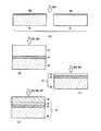
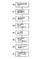
本発明の実施形態に従って、複合構造の製造方法、およびその後のエピタキシーによる半導体材料層、ここではIII/N族材料、の製造方法を、図1Aから図1Iおよび図2を
参照して説明する。In accordance with an embodiment of the present invention, a method of manufacturing a composite structure and a method of manufacturing a semiconductor material layer, here a III / N material, by epitaxy will be described with reference to FIGS. 1A to 1I and FIG.
エピタキシーのための複合構造の製造は、支持基板10の1つの面上における結合層12の堆積によって始まる(図1AのステップS1)。本実施形態においては、支持基板10はサファイア(Al2O3)から形成する。結合層12は、HTOシランの厚さがほぼ0.5μmになり得るような期間にわたる、800℃の堆積温度下でのLPCVDによって堆積させるHTOシランの層である。次に、堆積酸化物を、窒素雰囲気下で30分間にわたる、1200℃の温度下で実施する高密度化するアニール処理によって高密度化する(ステップS2)。Fabrication of the composite structure for epitaxy begins with the deposition of the
酸化物結合層12の表面を化学機械研磨(CMP)によって平坦化させて、5×5μm2の表面領域における表面粗さを5Å(オングストローム)RMSよりも小さくして、後
続の密着が促進されるようにする(図1BのステップS3)。研磨後は、層12は0.3μm±0.05μmの厚さを有する。The surface of the
酸化物層13を、サファイアから形成されたドナー基板11上に形成することもできる。層13は、厚さがほぼ0.2μmのHTOシランが堆積し得る期間にわたる、900℃の堆積温度下でのLPCVDによって堆積させたHTO DCSまたはHTOシランの層である(図1CのステップS4)。層13は、注入に対する保護層として作用する。 The
次に、注入を実施する。ドナー基板11は、酸化物層13を含む基板の平坦化面9への水素イオンH+の打ち込み20を受ける。H+イオンの注入は、注入量を1×10¹⁷atoms/cm2(アトムズ/スクウェアセンチメートル)から4×1017atoms/cm2
の範囲として、注入エネルギーを30keV(キロエレクトロンボルト)から200keVの範囲として実施する。注入は、1分から10時間にわたって、20℃から400℃の温度範囲で、好ましくは50℃から150℃の温度範囲で実施する。上記の注入の条件は、ドナー基板11内の所定の深さに、基板の面9に平行な欠陥層、言い換えれば脆弱層3、を形成し、基板11の上部の領域であって、結合層の厚さの位置に、5μmまたはそれ未満の厚さを有する薄膜4を規定し得る。また、基板の下部の領域である部分5は、基板1の残部に相当する(図1DのステップS5)。ヘリウムまたはアルゴンのような他の種のイオン注入を実施することもできる。また、水素およびヘリウムのような2種を混合しての同時注入を実施することもできる。Next, an injection is performed. The
The injection energy is set to a range of 30 keV (kiloelectron volts) to 200 keV. The injection is carried out in the temperature range of 20 ° C. to 400 ° C., preferably in the temperature range of 50 ° C. to 150 ° C., for 1 minute to 10 hours. The above implantation condition is that a defect layer parallel to the
次に、酸化物保護層13をアニール処理する(図1EのステップS6)。保護層を除去するために、取り除かれるべき層の性質に基づいて、適した化学的手法を用いる。例えば、シリコンの酸化物保護層は、HFの10%希釈溶液を用いたエッチングまたはBOE(buffered oxide etch)として知られている混合液によって容易に取り除かれる。 Next, the oxide
場合によっては、結合面を活性化させることができ、接着能力を向上させることができる、特に酸素、窒素またはアルゴンによるプラズマ処理を層12の表面およびドナー基板11の表面に実施してもよい(ステップS7,S7’)。 In some cases, the bonding surface can be activated and the adhesion capability can be improved, in particular plasma treatment with oxygen, nitrogen or argon may be carried out on the surface of the
次に、HTOシランの層12の面を、注入を受けたドナー基板11の面9に密着させて結合させる(図1FのステップS8)。結合は、ウェーハ接合によって実施する。ウェーハ接合による結合の原理は既知であるため、詳細な説明は割愛する。ウェーハ接合による結合は、例えば、(接着剤、ワックス、融点が低い金属などの)特定の材料を用いない、2つの表面の密着によるものであり、2つの表面間の密着力は大きいため、分子結合(結合する2つの表面の原子または分子の間の電子的相互作用による引力(ファンデルワールス力)の総和によって引き起こされる結合)を引き起こすことに留意されたい。 Next, the surface of the
次に、2つの基板の合成物に、脆弱な面3においてドナー基板11の断裂を生じさせ、支持基板10上に薄膜4の本体を転移させる、分割のためのアニール処理を施す(図1GのステップS9)。分割のためのアニール処理は、650℃で5時間にわたって実施する。 Next, the composite of the two substrates is subjected to an annealing treatment for splitting that causes the
さらに薄膜4の表面上で、変形を伴わない、結合の安定化のためのアニール処理を、1050℃で2時間にわたって実施する(ステップS10)。 Further, an annealing process for stabilizing the bond without deformation is performed on the surface of the
次に、例えば表面の凹凸の研磨、軽度の化学エッチング(図1HのステップS11)もしくはプラズマエッチング、または他の表面処理によって、膜4の表面がエピタキシーに適した表面になるようにしてもよい。 Next, the surface of the
これにより、図1Hに見られるような、支持基板10、LPCVDによって堆積させたHTOシランの酸化物結合層12および成長のための種結晶層として作用し得るサファイアの薄膜4を含む複合構造14が得られる。 This results in a
本実施形態では、窒化ガリウム(GaN)の層15のエピタキシャル成長を、薄膜4上で実施する(図1IのステップS12)。エピタキシャル成長は、例えばハロゲン化気相エピタキシー(HVPE)を用いて、1050℃で3時間にわたって実施する。上記のエピタキシーの後には、マイクロキャビティも剥離も全く観察されなかった。 In this embodiment, epitaxial growth of the gallium nitride (GaN)
本発明による複合構造の別の製造方法は、図3Aから図3Dおよび図4を参照されたい
。See FIGS. 3A-3D and 4 for another method of manufacturing a composite structure according to the present invention.
本実施形態では、例えばHTOシランまたはHTO DCSなどのシリコンの酸化物結合層を、ともにサファイアである支持基板20の面とドナー基板21の面の双方へのLPCVDによって堆積させる(図3AのステップS20)。支持基板20およびドナー基板21は、それぞれ酸化物結合層22a、22bを含む。 In the present embodiment, a silicon oxide bonding layer such as HTO silane or HTO DCS is deposited by LPCVD on both the surface of the
次に、酸化物結合層22a、22bを、2つの基板のウェーハ接合のために研磨する(ステップS21)。研磨後は、それぞれの層22a、22bは、最終的にはほぼ0.4μmの厚さを有する。 Next, the
層22a、層22bの研磨後に、それらをウェーハ接合によって2つの基板が結合するように密着させる(図3BのステップS22)。層22a、層22bの結合体は、ほぼ0.8μmの厚さを有する1つの堆積酸化物層22を形成する。 After the polishing of the
次に、結合の安定化のためのアニール処理を、1時間から5時間にわたって、200℃から800℃の間で実施する(ステップS23)。 Next, an annealing process for stabilizing the bond is performed between 200 ° C. and 800 ° C. for 1 to 5 hours (step S23).
ドナー基板21を、0.3μmの厚さにまで薄肉化する(図3CのステップS24)。薄肉化は、ドナー基板の面に対する機械的な研磨によって実施する。 The
図3Cに見られるように、このようにして、支持基板20、酸化物結合層22(HTO
DCSまたはHTOシラン)、および、ドナー基板21を薄肉化することによって得られ、エピタキシーのための結晶成長の種として作用し得る薄膜24を含む、エピタキシーのための複合構造23が得られる。As can be seen in FIG. 3C, in this way the
DCS or HTO silane) and a
さらに、複合構造23に、1時間にわたって1100℃で実施される2回目の結合の安定化のためのアニール処理を施してもよい(ステップS25)。 Further, the
薄膜24の表面を、表面粗さを小さくするための、化学機械研磨(CMP)、軽度の化学エッチングおよび/またはプラズマエッチングによってエピタキシーに適したものとしてもよい(ステップS26)。III/N族材料の層25のエピタキシャル成長は、マイク
ロキャビティも剥離も発生させることなく、薄膜24上で実施し得る(図3DのステップS27)。The surface of the
Claims (16)
Translated fromJapanese前記酸化物結合層(12または22)を、前記支持基板の結合面上および/または前記薄膜の結合面上における酸化物層の減圧化学気相成長(LPCVD)によって形成し、
前記薄膜(4または24)が、5マイクロメートルまたはそれ未満の厚さを有し、
前記酸化物結合層(12または22)の厚さが、前記薄膜(4または24)の厚さと同じまたはそれよりも大きい、
複合構造(14または23)の製造方法。And at least one thin film attached to a supporting substrate (10or 20) (4or 24), the oxide binding layer is formed by deposition between the supporting substrate (10or 20) and said thin film (4or 24) (12or 22), wherein the said thin film and said supporting substrate, 7 × having 10-6 K-1 or greater mean coefficient of thermal expansion than that, there in the manufacturing method of the composite structure (14or 23) And
Forming the oxide bonding layer (12or 22 ) by low pressure chemical vapor deposition (LPCVD) of an oxide layer on the bonding surface of the support substrate and / or on the bonding surface of the thin film;
The thin film (4or 24 ) has a thickness of 5 micrometers or less;
The thickness of the oxidebinding layer (12or 22 ) is equal to or greater than the thickness of the thin film (4or 24 );
A method for producing a composite structure (14or 23 ).
・前記ドナー基板(11)の前記1つの面(9)を前記支持基板(10)に密着させることによって結合する工程と、
・前記ドナー基板(11)内に形成した前記脆弱層(3)における分割によって、前記支持基板(10)に接する前記薄膜(4)を分離する工程と、
をさらに含む、請求項1〜4のいずれか一項に記載の製造方法。Ions are implanted and implanted into one surface (9) of the donor substrate (11) to form a fragile layer (3) at a predetermined depth in thedonor substrate, and theone surface (9) Defining the thin film (4) with a fragile layer (3);
Bonding by bringing theone surface (9) of the donor substrate (11) into intimate contact with the support substrate (10);
Separating the thin film (4) in contact with the support substrate (10) by dividing in the fragile layer (3) formed in the donor substrate (11);
The manufacturing method as described in any one of Claims 1-4 which further contains these.
・前記ドナー基板(21)を薄肉化して、前記薄膜(24)を形成する工程と、
をさらに含む、請求項1〜4のいずれか一項に記載の製造方法。Bonding by bringing one surface of the donor substrate (21) into intimate contact with the support substrate (20);
-Thinning the donor substrate (21) to form the thin film (24);
The manufacturing method as described in any one of Claims 1-4 which further contains these.
Applications Claiming Priority (3)
| Application Number | Priority Date | Filing Date | Title |
|---|---|---|---|
| FR0850359 | 2008-01-21 | ||
| FR0850359AFR2926674B1 (en) | 2008-01-21 | 2008-01-21 | METHOD FOR MANUFACTURING COMPOSITE STRUCTURE WITH STABLE BONDING OXIDE LAYER |
| PCT/EP2008/068311WO2009092506A2 (en) | 2008-01-21 | 2008-12-29 | A method of fabricating a composite structure with a stable bonding layer of oxide |
Publications (2)
| Publication Number | Publication Date |
|---|---|
| JP2011510503A JP2011510503A (en) | 2011-03-31 |
| JP5420569B2true JP5420569B2 (en) | 2014-02-19 |
Family
ID=39767085
Family Applications (1)
| Application Number | Title | Priority Date | Filing Date |
|---|---|---|---|
| JP2010543408AActiveJP5420569B2 (en) | 2008-01-21 | 2008-12-29 | Method for producing a composite structure having a stable oxide binding layer |
Country Status (8)
| Country | Link |
|---|---|
| US (2) | US20100190000A1 (en) |
| EP (1) | EP2232545B1 (en) |
| JP (1) | JP5420569B2 (en) |
| KR (1) | KR101534364B1 (en) |
| CN (1) | CN101925994B (en) |
| AT (1) | ATE556433T1 (en) |
| FR (1) | FR2926674B1 (en) |
| WO (1) | WO2009092506A2 (en) |
Families Citing this family (17)
| Publication number | Priority date | Publication date | Assignee | Title |
|---|---|---|---|---|
| FR2926674B1 (en)* | 2008-01-21 | 2010-03-26 | Soitec Silicon On Insulator | METHOD FOR MANUFACTURING COMPOSITE STRUCTURE WITH STABLE BONDING OXIDE LAYER |
| US20130264587A1 (en)* | 2012-04-04 | 2013-10-10 | Phostek, Inc. | Stacked led device using oxide bonding |
| FR3007892B1 (en)* | 2013-06-27 | 2015-07-31 | Commissariat Energie Atomique | METHOD FOR TRANSFERRING A THIN LAYER WITH THERMAL ENERGY SUPPLY TO A FRAGILIZED AREA VIA AN INDUCTIVE LAYER |
| FR3032555B1 (en)* | 2015-02-10 | 2018-01-19 | Soitec | METHOD FOR DEFERRING A USEFUL LAYER |
| JP6563360B2 (en)* | 2016-04-05 | 2019-08-21 | 信越化学工業株式会社 | Method for manufacturing composite wafer having oxide single crystal thin film |
| FR3068508B1 (en)* | 2017-06-30 | 2019-07-26 | Soitec | METHOD OF TRANSFERRING A THIN LAYER TO A SUPPORT SUBSTRATE HAVING DIFFERENT THERMAL EXPANSION COEFFICIENTS |
| FR3077923B1 (en)* | 2018-02-12 | 2021-07-16 | Soitec Silicon On Insulator | METHOD OF MANUFACTURING A SEMICONDUCTOR TYPE STRUCTURE ON INSULATION BY LAYER TRANSFER |
| FR3078822B1 (en)* | 2018-03-12 | 2020-02-28 | Soitec | PROCESS FOR THE PREPARATION OF A THIN LAYER OF ALKALINE BASED FERROELECTRIC MATERIAL |
| FR3079346B1 (en) | 2018-03-26 | 2020-05-29 | Soitec | METHOD FOR MANUFACTURING A DONOR SUBSTRATE FOR TRANSFERRING A PIEZOELECTRIC LAYER, AND METHOD FOR TRANSFERRING SUCH A PIEZOELECTRIC LAYER |
| US11315789B2 (en)* | 2019-04-24 | 2022-04-26 | Tokyo Electron Limited | Method and structure for low density silicon oxide for fusion bonding and debonding |
| JP7204625B2 (en)* | 2019-07-25 | 2023-01-16 | 信越化学工業株式会社 | Group III compound substrate manufacturing method and substrate manufactured by the manufacturing method |
| US11177250B2 (en)* | 2019-09-17 | 2021-11-16 | Tokyo Electron Limited | Method for fabrication of high density logic and memory for advanced circuit architecture |
| FR3108775B1 (en)* | 2020-03-27 | 2022-02-18 | Soitec Silicon On Insulator | METHOD FOR MANUFACTURING A COMPOSITE STRUCTURE COMPRISING A THIN MONOCRYSTALLINE SIC LAYER ON A SIC SUPPORT SUBSTRATE |
| FR3111232B1 (en)* | 2020-06-09 | 2022-05-06 | Soitec Silicon On Insulator | REMOVABLE TEMPORARY SUBSTRATE COMPATIBLE WITH VERY HIGH TEMPERATURES AND METHOD FOR TRANSFERRING A USEFUL LAYER FROM SAID SUBSTRATE |
| JP2023018972A (en)* | 2021-07-28 | 2023-02-09 | 信越化学工業株式会社 | Method for manufacturing spin wave excitation detection structure |
| CN113903834B (en)* | 2021-08-23 | 2023-10-13 | 华灿光电(浙江)有限公司 | Flip-chip red light diode chip and preparation method thereof |
| US20230187264A1 (en)* | 2021-12-13 | 2023-06-15 | Adeia Semiconductor Technologies Llc | Methods for bonding semiconductor elements |
Family Cites Families (40)
| Publication number | Priority date | Publication date | Assignee | Title |
|---|---|---|---|---|
| US255341A (en)* | 1882-03-21 | Tug-buckle | ||
| US76559A (en)* | 1868-04-07 | Alexander g | ||
| US241958A (en)* | 1881-05-24 | galland | ||
| US5882532A (en)* | 1996-05-31 | 1999-03-16 | Hewlett-Packard Company | Fabrication of single-crystal silicon structures using sacrificial-layer wafer bonding |
| US6251754B1 (en)* | 1997-05-09 | 2001-06-26 | Denso Corporation | Semiconductor substrate manufacturing method |
| US6245161B1 (en)* | 1997-05-12 | 2001-06-12 | Silicon Genesis Corporation | Economical silicon-on-silicon hybrid wafer assembly |
| FR2767604B1 (en) | 1997-08-19 | 2000-12-01 | Commissariat Energie Atomique | TREATMENT PROCESS FOR MOLECULAR GLUING AND TAKING OFF TWO STRUCTURES |
| JP2000349264A (en)* | 1998-12-04 | 2000-12-15 | Canon Inc | Method for manufacturing, using and using semiconductor wafer |
| FR2789518B1 (en)* | 1999-02-10 | 2003-06-20 | Commissariat Energie Atomique | MULTILAYER STRUCTURE WITH INTERNAL CONTROLLED STRESSES AND METHOD FOR PRODUCING SUCH A STRUCTURE |
| US6335263B1 (en)* | 2000-03-22 | 2002-01-01 | The Regents Of The University Of California | Method of forming a low temperature metal bond for use in the transfer of bulk and thin film materials |
| FR2816445B1 (en)* | 2000-11-06 | 2003-07-25 | Commissariat Energie Atomique | METHOD FOR MANUFACTURING A STACKED STRUCTURE COMPRISING A THIN LAYER ADHERING TO A TARGET SUBSTRATE |
| FR2894990B1 (en)* | 2005-12-21 | 2008-02-22 | Soitec Silicon On Insulator | PROCESS FOR PRODUCING SUBSTRATES, IN PARTICULAR FOR OPTICS, ELECTRONICS OR OPTOELECTRONICS AND SUBSTRATE OBTAINED BY SAID PROCESS |
| FR2817395B1 (en)* | 2000-11-27 | 2003-10-31 | Soitec Silicon On Insulator | METHOD FOR MANUFACTURING A SUBSTRATE, IN PARTICULAR FOR OPTICS, ELECTRONICS OR OPTOELECTRONICS AND SUBSTRATE OBTAINED THEREBY |
| FR2817394B1 (en)* | 2000-11-27 | 2003-10-31 | Soitec Silicon On Insulator | METHOD FOR MANUFACTURING A SUBSTRATE, IN PARTICULAR FOR OPTICS, ELECTRONICS OR OPTOELECTRONICS AND SUBSTRATE OBTAINED THEREBY |
| US7407869B2 (en)* | 2000-11-27 | 2008-08-05 | S.O.I.Tec Silicon On Insulator Technologies | Method for manufacturing a free-standing substrate made of monocrystalline semiconductor material |
| FR2835095B1 (en)* | 2002-01-22 | 2005-03-18 | PROCESS FOR PREPARING SEPARABLE SEMICONDUCTOR ASSEMBLIES, IN PARTICULAR FOR FORMING SUBSTRATES FOR ELECTRONICS, OPTOELECTRIC, AND OPTICS | |
| US7074623B2 (en)* | 2002-06-07 | 2006-07-11 | Amberwave Systems Corporation | Methods of forming strained-semiconductor-on-insulator finFET device structures |
| FR2845523B1 (en)* | 2002-10-07 | 2005-10-28 | METHOD FOR MAKING A SUBSTRATE BY TRANSFERRING A DONOR WAFER HAVING FOREIGN SPECIES, AND ASSOCIATED DONOR WAFER | |
| DE10325150A1 (en)* | 2003-05-31 | 2004-12-30 | Hahn-Meitner-Institut Berlin Gmbh | Parameterized semiconductor composite structure with integrated doping channels, process for the production and use thereof |
| US6911375B2 (en)* | 2003-06-02 | 2005-06-28 | International Business Machines Corporation | Method of fabricating silicon devices on sapphire with wafer bonding at low temperature |
| FR2857982B1 (en) | 2003-07-24 | 2007-05-18 | Soitec Silicon On Insulator | PROCESS FOR PRODUCING AN EPITAXIC LAYER |
| FR2857983B1 (en) | 2003-07-24 | 2005-09-02 | Soitec Silicon On Insulator | PROCESS FOR PRODUCING AN EPITAXIC LAYER |
| FR2860249B1 (en)* | 2003-09-30 | 2005-12-09 | Michel Bruel | METHOD FOR MANUFACTURING PLATE-LIKE STRUCTURE, ESPECIALLY SILICON, PROCESS APPLICATION, AND PLATE-LIKE STRUCTURE, PARTICULARLY SILICON |
| FR2864970B1 (en)* | 2004-01-09 | 2006-03-03 | Soitec Silicon On Insulator | SUPPORT SUBSTRATE WITH THERMAL EXPANSION COEFFICIENT DETERMINED |
| JP4796066B2 (en)* | 2004-09-16 | 2011-10-19 | エス.オー.アイ.テック シリコン オン インシュレータ テクノロジーズ | Method for producing a silicon dioxide layer |
| US7579621B2 (en)* | 2004-09-17 | 2009-08-25 | Massachusetts Institute Of Technology | Integrated BST microwave tunable devices using buffer layer transfer method |
| FR2877491B1 (en)* | 2004-10-29 | 2007-01-19 | Soitec Silicon On Insulator | COMPOSITE STRUCTURE WITH HIGH THERMAL DISSIPATION |
| JP5364368B2 (en)* | 2005-04-21 | 2013-12-11 | エイオーネックス・テクノロジーズ・インコーポレイテッド | Substrate manufacturing method |
| FR2888663B1 (en)* | 2005-07-13 | 2008-04-18 | Soitec Silicon On Insulator | METHOD OF REDUCING THE ROUGHNESS OF A THICK LAYER OF INSULATION |
| FR2890489B1 (en) | 2005-09-08 | 2008-03-07 | Soitec Silicon On Insulator | METHOD FOR MANUFACTURING A SEMICONDUCTOR TYPE HETEROSTRUCTURE ON INSULATION |
| JP5003033B2 (en)* | 2006-06-30 | 2012-08-15 | 住友電気工業株式会社 | GaN thin film bonded substrate and manufacturing method thereof, and GaN-based semiconductor device and manufacturing method thereof |
| JP2008153411A (en)* | 2006-12-18 | 2008-07-03 | Shin Etsu Chem Co Ltd | Manufacturing method of SOI substrate |
| FR2910179B1 (en)* | 2006-12-19 | 2009-03-13 | Commissariat Energie Atomique | METHOD FOR MANUFACTURING THIN LAYERS OF GaN BY IMPLANTATION AND RECYCLING OF A STARTING SUBSTRATE |
| JP5271279B2 (en)* | 2007-02-08 | 2013-08-21 | ソイテック | Method for manufacturing a high heat dissipation substrate |
| US7767542B2 (en)* | 2007-04-20 | 2010-08-03 | Semiconductor Energy Laboratory Co., Ltd | Manufacturing method of SOI substrate |
| JP5280015B2 (en)* | 2007-05-07 | 2013-09-04 | 信越半導体株式会社 | Manufacturing method of SOI substrate |
| US7763502B2 (en)* | 2007-06-22 | 2010-07-27 | Semiconductor Energy Laboratory Co., Ltd | Semiconductor substrate, method for manufacturing semiconductor substrate, semiconductor device, and electronic device |
| KR100976422B1 (en)* | 2007-12-28 | 2010-08-18 | 주식회사 하이닉스반도체 | Device Separator Formation Method of Semiconductor Device |
| FR2926674B1 (en)* | 2008-01-21 | 2010-03-26 | Soitec Silicon On Insulator | METHOD FOR MANUFACTURING COMPOSITE STRUCTURE WITH STABLE BONDING OXIDE LAYER |
| FR2926672B1 (en)* | 2008-01-21 | 2010-03-26 | Soitec Silicon On Insulator | PROCESS FOR MANUFACTURING LAYERS OF EPITAXY MATERIAL |
- 2008
- 2008-01-21FRFR0850359Apatent/FR2926674B1/ennot_activeExpired - Fee Related
- 2008-12-29EPEP08871508Apatent/EP2232545B1/enactiveActive
- 2008-12-29USUS12/663,693patent/US20100190000A1/ennot_activeAbandoned
- 2008-12-29WOPCT/EP2008/068311patent/WO2009092506A2/enactiveApplication Filing
- 2008-12-29KRKR1020107015993Apatent/KR101534364B1/enactiveActive
- 2008-12-29JPJP2010543408Apatent/JP5420569B2/enactiveActive
- 2008-12-29ATAT08871508Tpatent/ATE556433T1/enactive
- 2008-12-29CNCN200880125235.6Apatent/CN101925994B/enactiveActive
- 2013
- 2013-09-19USUS14/031,498patent/US9242444B2/enactiveActive
Also Published As
| Publication number | Publication date |
|---|---|
| WO2009092506A3 (en) | 2009-11-19 |
| US9242444B2 (en) | 2016-01-26 |
| CN101925994B (en) | 2017-05-17 |
| FR2926674A1 (en) | 2009-07-24 |
| WO2009092506A2 (en) | 2009-07-30 |
| US20140014029A1 (en) | 2014-01-16 |
| US20100190000A1 (en) | 2010-07-29 |
| CN101925994A (en) | 2010-12-22 |
| ATE556433T1 (en) | 2012-05-15 |
| KR20100103617A (en) | 2010-09-27 |
| KR101534364B1 (en) | 2015-07-06 |
| JP2011510503A (en) | 2011-03-31 |
| FR2926674B1 (en) | 2010-03-26 |
| EP2232545B1 (en) | 2012-05-02 |
| EP2232545A2 (en) | 2010-09-29 |
Similar Documents
| Publication | Publication Date | Title |
|---|---|---|
| JP5420569B2 (en) | Method for producing a composite structure having a stable oxide binding layer | |
| CN101925995B (en) | Method of fabricating epitaxially grown layers on composite structure | |
| JP5567569B2 (en) | Method of manufacturing a semiconductor structure or semiconductor device using a layer of semiconductor material having a selected or controlled lattice constant | |
| US8154022B2 (en) | Process for fabricating a structure for epitaxy without an exclusion zone | |
| JP4733633B2 (en) | Epitaxial substrate manufacturing method | |
| TWI527099B (en) | Process for recycling a substrate | |
| CN101714505B (en) | Relaxation of a strained material layer with application of a stiffener | |
| JP2006140445A (en) | Manufacturing method of composite material wafer | |
| JP2005515150A (en) | Method for manufacturing free-standing substrate made of single crystal semiconductor material | |
| TW201029049A (en) | Process for modifying a substrate | |
| JP2011515838A (en) | Method for fabricating a semiconductor-on-insulator type substrate | |
| CN102349148B (en) | Adaptation of the lattice parameter of layer of strained material | |
| US8263984B2 (en) | Process for making a GaN substrate | |
| JP2008532328A (en) | Method for manufacturing a heterostructure comprising at least one thick layer of semiconductor material | |
| CN1971850A (en) | Relaxation of layers | |
| TW200529459A (en) | Wafer bonded epitaxial templates for silicon heterostructures | |
| FR2914494A1 (en) | Thin film e.g. gallium nitride thin film, transferring method for e.g. microwave field, involves forming adhesion layer on substrate, and thinning substrate by breaking at fragile area created by fragilization of substrate to form thin film |
Legal Events
| Date | Code | Title | Description |
|---|---|---|---|
| A621 | Written request for application examination | Free format text:JAPANESE INTERMEDIATE CODE: A621 Effective date:20110801 | |
| A977 | Report on retrieval | Free format text:JAPANESE INTERMEDIATE CODE: A971007 Effective date:20130627 | |
| A131 | Notification of reasons for refusal | Free format text:JAPANESE INTERMEDIATE CODE: A131 Effective date:20130716 | |
| A521 | Request for written amendment filed | Free format text:JAPANESE INTERMEDIATE CODE: A523 Effective date:20131004 | |
| TRDD | Decision of grant or rejection written | ||
| A01 | Written decision to grant a patent or to grant a registration (utility model) | Free format text:JAPANESE INTERMEDIATE CODE: A01 Effective date:20131029 | |
| A61 | First payment of annual fees (during grant procedure) | Free format text:JAPANESE INTERMEDIATE CODE: A61 Effective date:20131120 | |
| R150 | Certificate of patent or registration of utility model | Ref document number:5420569 Country of ref document:JP Free format text:JAPANESE INTERMEDIATE CODE: R150 | |
| R250 | Receipt of annual fees | Free format text:JAPANESE INTERMEDIATE CODE: R250 | |
| R250 | Receipt of annual fees | Free format text:JAPANESE INTERMEDIATE CODE: R250 | |
| R250 | Receipt of annual fees | Free format text:JAPANESE INTERMEDIATE CODE: R250 | |
| R250 | Receipt of annual fees | Free format text:JAPANESE INTERMEDIATE CODE: R250 | |
| R250 | Receipt of annual fees | Free format text:JAPANESE INTERMEDIATE CODE: R250 | |
| R250 | Receipt of annual fees | Free format text:JAPANESE INTERMEDIATE CODE: R250 | |
| R250 | Receipt of annual fees | Free format text:JAPANESE INTERMEDIATE CODE: R250 | |
| R250 | Receipt of annual fees | Free format text:JAPANESE INTERMEDIATE CODE: R250 | |
| R250 | Receipt of annual fees | Free format text:JAPANESE INTERMEDIATE CODE: R250 |