JP5420542B2 - Air cleaner arrangements, components and methods having internal and external supports for cartridges - Google Patents
Air cleaner arrangements, components and methods having internal and external supports for cartridgesDownload PDFInfo
- Publication number
- JP5420542B2 JP5420542B2JP2010517159AJP2010517159AJP5420542B2JP 5420542 B2JP5420542 B2JP 5420542B2JP 2010517159 AJP2010517159 AJP 2010517159AJP 2010517159 AJP2010517159 AJP 2010517159AJP 5420542 B2JP5420542 B2JP 5420542B2
- Authority
- JP
- Japan
- Prior art keywords
- end cap
- central
- cartridge
- support
- housing
- Prior art date
- Legal status (The legal status is an assumption and is not a legal conclusion. Google has not performed a legal analysis and makes no representation as to the accuracy of the status listed.)
- Expired - Fee Related
Links
- 238000000034methodMethods0.000titledescription4
- 238000004804windingMethods0.000claimsdescription21
- 238000007689inspectionMethods0.000claimsdescription6
- 230000002093peripheral effectEffects0.000description21
- WYTGDNHDOZPMIW-RCBQFDQVSA-NalstonineNatural productsC1=CC2=C3C=CC=CC3=NC2=C2N1C[C@H]1[C@H](C)OC=C(C(=O)OC)[C@H]1C2WYTGDNHDOZPMIW-RCBQFDQVSA-N0.000description16
- 238000001914filtrationMethods0.000description12
- 238000009434installationMethods0.000description9
- 230000003993interactionEffects0.000description8
- 239000000853adhesiveSubstances0.000description6
- 230000001070adhesive effectEffects0.000description6
- 229920003023plasticPolymers0.000description6
- 239000004033plasticSubstances0.000description6
- 229920002635polyurethanePolymers0.000description6
- 239000004814polyurethaneSubstances0.000description6
- 239000000463materialSubstances0.000description5
- 238000000465mouldingMethods0.000description4
- 238000007789sealingMethods0.000description4
- 239000011324beadSubstances0.000description3
- 230000008901benefitEffects0.000description3
- 239000002131composite materialSubstances0.000description3
- 239000002184metalSubstances0.000description3
- 229920000122acrylonitrile butadiene styrenePolymers0.000description2
- 238000002485combustion reactionMethods0.000description2
- 238000007373indentationMethods0.000description2
- 241000196324EmbryophytaSpecies0.000description1
- 239000004743PolypropyleneSubstances0.000description1
- 230000001154acute effectEffects0.000description1
- 230000000712assemblyEffects0.000description1
- 238000000429assemblyMethods0.000description1
- 238000005266castingMethods0.000description1
- 238000004140cleaningMethods0.000description1
- 230000006835compressionEffects0.000description1
- 238000007906compressionMethods0.000description1
- 238000010276constructionMethods0.000description1
- 238000010586diagramMethods0.000description1
- 239000000428dustSubstances0.000description1
- 239000011521glassSubstances0.000description1
- 238000003780insertionMethods0.000description1
- 230000037431insertionEffects0.000description1
- 238000012423maintenanceMethods0.000description1
- 239000000203mixtureSubstances0.000description1
- 239000002991molded plasticSubstances0.000description1
- -1polypropylenePolymers0.000description1
- 229920001155polypropylenePolymers0.000description1
- 238000004382pottingMethods0.000description1
- 230000003014reinforcing effectEffects0.000description1
- 238000000926separation methodMethods0.000description1
- XLYOFNOQVPJJNP-UHFFFAOYSA-NwaterSubstancesOXLYOFNOQVPJJNP-UHFFFAOYSA-N0.000description1
Images


Classifications
- B—PERFORMING OPERATIONS; TRANSPORTING
- B01—PHYSICAL OR CHEMICAL PROCESSES OR APPARATUS IN GENERAL
- B01D—SEPARATION
- B01D46/00—Filters or filtering processes specially modified for separating dispersed particles from gases or vapours
- B—PERFORMING OPERATIONS; TRANSPORTING
- B01—PHYSICAL OR CHEMICAL PROCESSES OR APPARATUS IN GENERAL
- B01D—SEPARATION
- B01D46/00—Filters or filtering processes specially modified for separating dispersed particles from gases or vapours
- B01D46/24—Particle separators, e.g. dust precipitators, using rigid hollow filter bodies
- B01D46/2403—Particle separators, e.g. dust precipitators, using rigid hollow filter bodies characterised by the physical shape or structure of the filtering element
- B01D46/2411—Filter cartridges
- B01D46/2414—End caps including additional functions or special forms
- B—PERFORMING OPERATIONS; TRANSPORTING
- B01—PHYSICAL OR CHEMICAL PROCESSES OR APPARATUS IN GENERAL
- B01D—SEPARATION
- B01D46/00—Filters or filtering processes specially modified for separating dispersed particles from gases or vapours
- B01D46/24—Particle separators, e.g. dust precipitators, using rigid hollow filter bodies
- B—PERFORMING OPERATIONS; TRANSPORTING
- B01—PHYSICAL OR CHEMICAL PROCESSES OR APPARATUS IN GENERAL
- B01D—SEPARATION
- B01D46/00—Filters or filtering processes specially modified for separating dispersed particles from gases or vapours
- B01D46/0002—Casings; Housings; Frame constructions
- B—PERFORMING OPERATIONS; TRANSPORTING
- B01—PHYSICAL OR CHEMICAL PROCESSES OR APPARATUS IN GENERAL
- B01D—SEPARATION
- B01D46/00—Filters or filtering processes specially modified for separating dispersed particles from gases or vapours
- B01D46/0002—Casings; Housings; Frame constructions
- B01D46/0004—Details of removable closures, lids, caps or filter heads
- B—PERFORMING OPERATIONS; TRANSPORTING
- B01—PHYSICAL OR CHEMICAL PROCESSES OR APPARATUS IN GENERAL
- B01D—SEPARATION
- B01D46/00—Filters or filtering processes specially modified for separating dispersed particles from gases or vapours
- B01D46/0002—Casings; Housings; Frame constructions
- B01D46/0005—Mounting of filtering elements within casings, housings or frames
- B—PERFORMING OPERATIONS; TRANSPORTING
- B01—PHYSICAL OR CHEMICAL PROCESSES OR APPARATUS IN GENERAL
- B01D—SEPARATION
- B01D46/00—Filters or filtering processes specially modified for separating dispersed particles from gases or vapours
- B01D46/0002—Casings; Housings; Frame constructions
- B01D46/0012—In-line filters
- B—PERFORMING OPERATIONS; TRANSPORTING
- B01—PHYSICAL OR CHEMICAL PROCESSES OR APPARATUS IN GENERAL
- B01D—SEPARATION
- B01D46/00—Filters or filtering processes specially modified for separating dispersed particles from gases or vapours
- B01D46/0002—Casings; Housings; Frame constructions
- B01D46/0013—Modules
- B—PERFORMING OPERATIONS; TRANSPORTING
- B01—PHYSICAL OR CHEMICAL PROCESSES OR APPARATUS IN GENERAL
- B01D—SEPARATION
- B01D46/00—Filters or filtering processes specially modified for separating dispersed particles from gases or vapours
- B01D46/0084—Filters or filtering processes specially modified for separating dispersed particles from gases or vapours provided with safety means
- B01D46/009—Identification of filter type or position thereof, e.g. by transponders or bar codes
- B—PERFORMING OPERATIONS; TRANSPORTING
- B01—PHYSICAL OR CHEMICAL PROCESSES OR APPARATUS IN GENERAL
- B01D—SEPARATION
- B01D46/00—Filters or filtering processes specially modified for separating dispersed particles from gases or vapours
- B01D46/24—Particle separators, e.g. dust precipitators, using rigid hollow filter bodies
- B01D46/2403—Particle separators, e.g. dust precipitators, using rigid hollow filter bodies characterised by the physical shape or structure of the filtering element
- B01D46/2411—Filter cartridges
- B—PERFORMING OPERATIONS; TRANSPORTING
- B01—PHYSICAL OR CHEMICAL PROCESSES OR APPARATUS IN GENERAL
- B01D—SEPARATION
- B01D46/00—Filters or filtering processes specially modified for separating dispersed particles from gases or vapours
- B01D46/42—Auxiliary equipment or operation thereof
- B—PERFORMING OPERATIONS; TRANSPORTING
- B01—PHYSICAL OR CHEMICAL PROCESSES OR APPARATUS IN GENERAL
- B01D—SEPARATION
- B01D46/00—Filters or filtering processes specially modified for separating dispersed particles from gases or vapours
- B01D46/56—Filters or filtering processes specially modified for separating dispersed particles from gases or vapours with multiple filtering elements, characterised by their mutual disposition
- B01D46/62—Filters or filtering processes specially modified for separating dispersed particles from gases or vapours with multiple filtering elements, characterised by their mutual disposition connected in series
- B01D46/64—Filters or filtering processes specially modified for separating dispersed particles from gases or vapours with multiple filtering elements, characterised by their mutual disposition connected in series arranged concentrically or coaxially
- B—PERFORMING OPERATIONS; TRANSPORTING
- B01—PHYSICAL OR CHEMICAL PROCESSES OR APPARATUS IN GENERAL
- B01D—SEPARATION
- B01D46/00—Filters or filtering processes specially modified for separating dispersed particles from gases or vapours
- B01D46/88—Replacing filter elements
- F—MECHANICAL ENGINEERING; LIGHTING; HEATING; WEAPONS; BLASTING
- F02—COMBUSTION ENGINES; HOT-GAS OR COMBUSTION-PRODUCT ENGINE PLANTS
- F02M—SUPPLYING COMBUSTION ENGINES IN GENERAL WITH COMBUSTIBLE MIXTURES OR CONSTITUENTS THEREOF
- F02M35/00—Combustion-air cleaners, air intakes, intake silencers, or induction systems specially adapted for, or arranged on, internal-combustion engines
- F02M35/02—Air cleaners
- F02M35/024—Air cleaners using filters, e.g. moistened
- F02M35/02416—Fixing, mounting, supporting or arranging filter elements; Filter element cartridges
- B—PERFORMING OPERATIONS; TRANSPORTING
- B01—PHYSICAL OR CHEMICAL PROCESSES OR APPARATUS IN GENERAL
- B01D—SEPARATION
- B01D2265/00—Casings, housings or mounting for filters specially adapted for separating dispersed particles from gases or vapours
- B01D2265/02—Non-permanent measures for connecting different parts of the filter
- B01D2265/021—Anti-rotational means
- B—PERFORMING OPERATIONS; TRANSPORTING
- B01—PHYSICAL OR CHEMICAL PROCESSES OR APPARATUS IN GENERAL
- B01D—SEPARATION
- B01D2265/00—Casings, housings or mounting for filters specially adapted for separating dispersed particles from gases or vapours
- B01D2265/02—Non-permanent measures for connecting different parts of the filter
- B01D2265/024—Mounting aids
- B01D2265/026—Mounting aids with means for avoiding false mounting
- B—PERFORMING OPERATIONS; TRANSPORTING
- B01—PHYSICAL OR CHEMICAL PROCESSES OR APPARATUS IN GENERAL
- B01D—SEPARATION
- B01D2265/00—Casings, housings or mounting for filters specially adapted for separating dispersed particles from gases or vapours
- B01D2265/02—Non-permanent measures for connecting different parts of the filter
- B01D2265/028—Snap, latch or clip connecting means
- B—PERFORMING OPERATIONS; TRANSPORTING
- B01—PHYSICAL OR CHEMICAL PROCESSES OR APPARATUS IN GENERAL
- B01D—SEPARATION
- B01D2267/00—Multiple filter elements specially adapted for separating dispersed particles from gases or vapours
- B01D2267/40—Different types of filters
- B—PERFORMING OPERATIONS; TRANSPORTING
- B01—PHYSICAL OR CHEMICAL PROCESSES OR APPARATUS IN GENERAL
- B01D—SEPARATION
- B01D2271/00—Sealings for filters specially adapted for separating dispersed particles from gases or vapours
- B01D2271/02—Gaskets, sealings
- B01D2271/027—Radial sealings
- B—PERFORMING OPERATIONS; TRANSPORTING
- B01—PHYSICAL OR CHEMICAL PROCESSES OR APPARATUS IN GENERAL
- B01D—SEPARATION
- B01D2279/00—Filters adapted for separating dispersed particles from gases or vapours specially modified for specific uses
- B01D2279/60—Filters adapted for separating dispersed particles from gases or vapours specially modified for specific uses for the intake of internal combustion engines or turbines
Landscapes
- Chemical & Material Sciences (AREA)
- Chemical Kinetics & Catalysis (AREA)
- Physics & Mathematics (AREA)
- Geometry (AREA)
- Engineering & Computer Science (AREA)
- Combustion & Propulsion (AREA)
- Mechanical Engineering (AREA)
- General Engineering & Computer Science (AREA)
- Filtering Of Dispersed Particles In Gases (AREA)
- Respiratory Apparatuses And Protective Means (AREA)
- Disinfection, Sterilisation Or Deodorisation Of Air (AREA)
- Packages (AREA)
Description
Translated fromJapanese本開示は、カートリッジ用に内部及び外部の支持体を持つエアクリーナの配置物、コンポーネントおよび方法に関する。 The present disclosure relates to air cleaner arrangements, components and methods for cartridges having internal and external supports.
本出願は、米国以外の全ての国を指定国とする出願人である米国国内企業であるドナルドソン会社と、米国のみを指定国とする出願人である、全てベルギー人であるミシェル・バセオトー、ロベルト・メルクス、ジュリアン・ディルス、ポール・R・クーロンボウクスの名において、国際特許出願として2008年7月12日に出願されたものであり、2007年7月20日に出願された米国仮特許出願第60/961,521号と2008年4月30日に出願された米国仮特許出願第61/126,222号の優先権を主張するものである。 This application consists of Donaldson Company, a U.S. company that is an applicant whose designated country is all countries other than the U.S., and Michel Basseoto, who is an Belgian-only applicant, who is an U.S.-only designated country. United States provisional patent filed on July 12, 2008, filed on July 12, 2008 as an international patent application in the names of Roberto Mercks, Julian Dills, Paul R. Coulombs No. 60 / 961,521 and US Provisional Patent Application No. 61 / 126,222 filed Apr. 30, 2008.
エアクリーナは、さまざまな乗り物およびトラック、バス、路外の建設用機器、農業機器、発電機セットなどの他の装置の内燃機関エンジンの燃焼吸気をろ過するために使用される。そのようなエアクリーナは、通常は、その中に配置された取り外し可能で取替え可能なメインフィルタカートリッジを持つハウジングを含む。ハウジングは、整備点検のために、内側に収容されたフィルタカートリッジへの選択されたアクセスのための点検またはアクセスカバーを含む。フィルタカートリッジは、通常は、取り外された後、工場からの新しいカートリッジと取り替えることによって、または、洗浄して再設置することによって、または、前に使用された洗浄していないカートリッジと取り替えることによって、点検整備される。 Air cleaners are used to filter the combustion intake of internal combustion engine engines in various vehicles and other devices such as trucks, buses, offshore construction equipment, agricultural equipment, generator sets and the like. Such air cleaners typically include a housing having a removable and replaceable main filter cartridge disposed therein. The housing includes an inspection or access cover for selected access to the filter cartridge housed therein for maintenance. The filter cartridge is usually removed and then replaced by a new cartridge from the factory, or by cleaning and re-installing, or by replacing a previously used uncleaned cartridge. Inspected and maintained.
点検可能なフィルタカートリッジを持つエアクリーナの配置に関連する問題点は、適切な取り付けとシールを確実にすること、意図しない動きまたは運動に対してエアクリーナ中のフィルタカートリッジを適切に支持すること、および/または、エアクリーナハウジングがフィルタカートリッジの不適切な取り付けに対して確実に保護されていること、を含む。 Problems associated with the placement of an air cleaner with a serviceable filter cartridge include ensuring proper installation and sealing, properly supporting the filter cartridge in the air cleaner against unintended movement or movement, and / or Or including that the air cleaner housing is securely protected against improper installation of the filter cartridge.
これらの問題点に向けられたエアクリーナ用アセンブリとそのフィルタカートリッジの改良について、本明細書に記載する。 Improvements to the air cleaner assembly and its filter cartridge that address these problems are described herein.
したがって、本開示では、エアクリーナの配置物とコンポーネントを提供する。図示したエアクリーナの配置物は、複数の特徴を含む。エアクリーナ用アセンブリ、および/または、コンポーネントがいくつかの利点を得るために、本明細書で特徴付けられた特徴の全てを含むという特別な必要性は全くない。 Accordingly, the present disclosure provides air cleaner arrangements and components. The illustrated air cleaner arrangement includes a plurality of features. There is no particular need for an air cleaner assembly and / or component to include all of the features characterized herein in order to obtain several advantages.
第1のフィルタカートリッジを取り付ける間に、開いているカートリッジ内部に伸びるようにハウジングに取り付けられているカートリッジ支持体によって、第1のフィルタカートリッジ用の内部の支持体を提供する例示のエアクリーナ配置物を図示する。内部の支持体は、2次あるいは安全フィルタ用の媒体の支持体として使用することができる。フィルタカートリッジとカートリッジ支持体との係合によって、フィルタカートリッジの閉じた端部で片持ちばりの支持と、フィルタカートリッジとカートリッジ支持体との間で回転しない支持と、の両方を提供するように選択することができる。 An exemplary air cleaner arrangement that provides an internal support for the first filter cartridge by a cartridge support attached to the housing so as to extend inside the open cartridge during installation of the first filter cartridge. Illustrated. The internal support can be used as a support for secondary or safety filter media. Selectable to provide both cantilevered support at the closed end of the filter cartridge and non-rotating support between the filter cartridge and cartridge support by engagement of the filter cartridge and cartridge support can do.
アクセスカバーは、フィルタカートリッジの閉じた端部と係合するように提供される。アクセスカバーは、片持ちばりの支持と、回転しないカートリッジの支持と、の両方を可能にする構造物の配置を提供することができる。 An access cover is provided to engage the closed end of the filter cartridge. The access cover can provide an arrangement of structures that allows both cantilever support and non-rotating cartridge support.
本明細書では、エアクリーナで使用するコンポーネントを記載する。記載した例示のコンポーネントは、第1のフィルタカートリッジ、オプションの第2のフィルタカートリッジ、およびアクセスカバーを含む。 This specification describes the components used in the air cleaner. The exemplary components described include a first filter cartridge, an optional second filter cartridge, and an access cover.
例示の第1のフィルタカートリッジを提供する。第1のフィルタカートリッジは、開いた第1端部キャップから遠く離れている第2端部キャップまたは閉じた端部キャップを含む。第2端部キャップは、受け溝を、通常は、曲がりくねった受け溝をその中に持つ外面を含む。別の表面もまた、アクセスカバー上の受け部中に伸びている突起物とともに提供することができる。 An exemplary first filter cartridge is provided. The first filter cartridge includes a second end cap or a closed end cap that is remote from the open first end cap. The second end cap includes a receiving groove, typically an outer surface having a tortuous receiving groove therein. Another surface can also be provided with a protrusion extending into the receptacle on the access cover.
第2端部キャップの内面は、カートリッジ支持体と係合するように構成されている。第2端部キャップの内面は、カートリッジ支持体によって第2端部のフィルタカートリッジの片持ちばりの支持と、フィルタカートリッジとカートリッジ支持体との間の回転しない係合と、のうちの1つまたは両方を提供するように構成することができる。 The inner surface of the second end cap is configured to engage the cartridge support. The inner surface of the second end cap is one of a support for the cantilever of the filter cartridge at the second end by the cartridge support and a non-rotating engagement between the filter cartridge and the cartridge support or It can be configured to provide both.
本開示の別の態様では、シール突起物を持つ開いている端部をその上に含むフィルタカートリッジを提供する。シールの支持体は、シール突起物中に埋め込まれている。例示では、シール突起物は、空気流れの開口部を持つ端部キャップの残りの部分と一体となっている。図示した特別の例では、シールの支持体はインナーライナと一体となっており、インナーライナは、媒体の支持体の周囲に提供される。また、インナーライナは、媒体パックの肩部を含むことができ、媒体パックの肩部に対して媒体パックが配置されている。 In another aspect of the present disclosure, a filter cartridge is provided that includes an open end thereon with a seal protrusion. The seal support is embedded in the seal projection. Illustratively, the seal projection is integral with the rest of the end cap having an air flow opening. In the particular example illustrated, the seal support is integral with the inner liner, which is provided around the media support. The inner liner can also include a shoulder of the media pack, and the media pack is disposed with respect to the shoulder of the media pack.
I.例示のアセンブリ
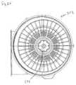
図1の符号1は、本開示の例示のエアクリーナ用アセンブリを一般的に示したものである。エアクリーナ用アセンブリ1は、ハウジング本体3とアクセスカバー4とを有するハウジング2を含む。アクセスカバー4は、接続配置物7によってハウジング本体3上の適所に固定されている。示された例では、接続配置物7は、複数のラッチ8を含む。I. Exemplary Assembly Reference numeral 1 in FIG. 1 generally illustrates an exemplary air cleaner assembly of the present disclosure. The air
ハウジング本体3は、開いている第1端部10aを持つ側壁10を含み、第1端部10aにアクセスカバー4が取り付けられている。ハウジング側壁は、第1端部10aに対向する第2端部10bを含む。第2端部10bは、空気流の開口部または空気流の開口ポート12を持つハウジング側壁11をその上に含む。ハウジング端部壁11は、通常は、側壁10から取り外し可能ではなく、ある場合には、側壁10と一体成形されている。通常の例では、アクセスカバー4とハウジング本体3は、選択された形状に成形されたガラス充填ポリプロピレンを含む。 The
一般に、アクセスカバー4は、接続配置物7(すなわち、ラッチ8)を外すとき、アクセスカバー4をハウジング本体3から取り外すか、または端部10aを通してハウジング本体3の内部にアクセス可能にする位置に移動することができる方法で取り付けられる。図1で図示された特別の例示のエアクリーナ用アセンブリ1において、アクセスカバー4は、ラッチ8によりハウジング本体3に取り外し可能に取り付けられている。 Generally, the
エアクリーナ用アセンブリ1は、さらに、ハウジング2の内部と空気流が連通する空気流のポートまたは空気流の開口部15を含む。示された特別の例では、空気流の開口部15は、側壁10の空気流入部であり、空気流の開口ポート12は、空気流出部である。但し、代替手段は可能である。 The air
また、図1を参照すると、ハウジング本体3は、取付配置物20をその上に含む。エアクリーナ用アセンブリ1は、使用の間に取付配置物20によって、取付装置の上に、例えば、乗り物のフレームあるいは装置のフレームなどのの上に固定することができる。図示された特別の取付配置物20は、複数の取付用パッド21を含む。 Referring also to FIG. 1, the
取付用パッド21は、エアクリーナ用アセンブリ1を使用する装置のフレームあるいは他の部分に便利に固定するために、ハウジング本体2上の様々な場所に配置することができる。取付用パッド21は、全て使用するわけではないようなさまざまな位置に配置することができるが、使用される配置は、装置の特別な形状に依存することが注目される。したがって、ハウジング本体2は、選択された取り付けにおいて、実際に使用しない取付用パッド21を含んでもよい。 The mounting
図1において、図示された例示の配置物の例示の寸法は、AA=607mm、AB=346.1mm、AC=174.5mm、AD=366.6mm、AE=102mmである。もちろん、本開示の原理は、さまざまな大きさのユニットに適用することができ、寸法は、単に例を示すものである。 In FIG. 1, exemplary dimensions of the illustrated exemplary arrangement are AA = 607 mm, AB = 346.1 mm, AC = 174.5 mm, AD = 366.6 mm, AE = 102 mm. Of course, the principles of the present disclosure can be applied to units of various sizes, and the dimensions are merely examples.
図2を参照すると、エアクリーナ用アセンブリ1は、アクセスカバー4と入口開口部15に向かう方向に斜視図で示されている。また、ハウジング2、例えば、側壁10は、取り付けの時に、あるいは、取り付けの向きに、エアクリーナ用アセンブリ1の取付装置の多様性を可能にするさまざまな配置の取付用パッド21とともに、提供することができる。 Referring to FIG. 2, the air
また図2を参照すると、図示されたエアクリーナ用アセンブリ1は、吸引バルブ配置物25をその上に含む。吸引バルブ配置物25は、使用時に、水、および/または、あらかじめ分離されたダストをハウジング2の内部2iから排出することができるダイアフラムあるいは他のバルブ部材を含む。 Referring also to FIG. 2, the illustrated air
また図2を参照すると、アクセスカバー4は、周囲リム30と端面31とを含むことが着目される。端面31は、外側に向いている中央突起物33をその上に持つ中央のくぼみ32を含む。これらの特徴は、以下でさらに説明される。 Referring also to FIG. 2, it is noted that the
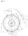
図3に、アクセスカバー4に向かって得られるエアクリーナ1の端面図を示す。エアクリーナ1を取り付けるとき、通常は、吸引バルブ配置物25を下向きに向ける。したがって、図3の端面図は、一般的な通常の取り付け配置である。 FIG. 3 shows an end view of the
図3では、図示された例示システムのための例示の寸法と角度は、BA=120°、BB=30°、BC=10mm、BD=178mm、BE=30°、BF=146.3mm、BG=185.5mm、BH=31.7mm、およびBI=246.5mmである。 In FIG. 3, exemplary dimensions and angles for the illustrated exemplary system are: BA = 120 °, BB = 30 °, BC = 10 mm, BD = 178 mm, BE = 30 °, BF = 146.3 mm, BG = 185.5 mm, BH = 31.7 mm, and BI = 246.5 mm.
ここで、エアクリーナ用アセンブリ1を分解図で示す図4に着目する。図1のエアクリーナ用アセンブリ1の内部に収容されたコンポーネントを見ることができる。特に、第1のフィルタカートリッジ40を見ることができる。また、オプションの安全フィルタ41が示される。最後に、エアクリーナ用アセンブリ1を組み立てるとき、アクセスカバー4とハウジング本体3との間に配置されるOリング42が示される。 Attention is now directed to FIG. 4 showing the air
図5は、エアクリーナ用アセンブリ1の断面図を示し、選択された内部構造の詳細を見ることができる。一般に、ハウジング2は、エアフィルタ用の第1カートリッジあるいは第1のカートリッジ40を収容するハウジング内部2iを画定する。空気は、入口(空気流入部)15を通って内部2iに入り、エアフィルタ用カートリッジ40を取り囲む空気流環部45に送出される。空気は、ろ過の間、エアフィルタ用カートリッジ40に外から内(out-to-in)への流れパターンで導かれる。一般に、エアフィルタ用カートリッジ40は、空気ろ過用媒体51をその中に持つ媒体パック50を含む。媒体パック50を通過するときに、空気はろ過される。ろ過された空気は、内部のカートリッジ支持体55を通り、次に、外方向に出口(空気流出部)12を通る。 FIG. 5 shows a cross-sectional view of the air
内部のカートリッジ支持体55は、いくつかの応用において、オプションの安全フィルタ41の媒体41aによって取り囲まれている。そのような応用では、空気は、カートリッジ支持体55中に入り、安全フィルタ41の媒体41aを通過する。安全フィルタまたは第2のフィルタを必要としない応用では、安全フィルタ41を外すことができる。 The
「前進する流れ」の配置における一般的な記載を提供する。「前進する流れ」により、ろ過の間に、空気流れは、第1のエアフィルタ用カートリッジ40の外側から媒体パック50によって画定される開いている内部60まで通過する(すなわち、外から内)ことを意味する。本明細書に記載される選択された原理は、ろ過の間、流れの向きが逆である代替の配置あるいは逆の流れの配置に適用することができる。すなわち、逆の流れの配置では、ろ過の間、空気流れは、内部領域60から媒体パック50を通る。 Provides a general description of the “forward flow” arrangement. By “advancing flow”, during filtration, air flow passes from the outside of the first
通常のエアクリーナでは、入口開口ポート(空気流入部)15は、構造15a(および構造12aによって取り囲まれている出口開口ポート(空気流出部)12)によって取り囲まれている。使用のために構造15aにダクトワークまたは他の流路装置を取り付けることができる。 In a normal air cleaner, the inlet opening port (air inflow portion) 15 is surrounded by the structure 15a (and the outlet opening port (air outflow portion) 12 surrounded by the structure 12a). Ductwork or other flow path devices can be attached to the structure 15a for use.
図5では、エアクリーナ用アセンブリ1は、便宜上、その上に取り付けられたラッチ8を省いて示していることが注意される。 In FIG. 5, it is noted that the air
また図5を参照すると、エアフィルタ用第1カートリッジ40は、サービスコンポーネントであり、内部2iで、エアフィルタ用カートリッジ40やハウジング2に損傷与えずに取り外し可能でかつ取替え可能である。内部2iへの点検のためのアクセスは、アクセスカバー4を開くことによって提供される。通常は、点検のためのアクセスは、側壁10の端部10aからアクセス4を取り除くことによって行われる。 Referring also to FIG. 5, the first
エアフィルタ用カートリッジ40は点検コンポーネントであるので、ろ過されていない空気が出口12中に流れるのを避けるために、エアクリーナハウジング2中で取り外し可能にシールされる必要がある。このために、ハウジングシール配置物65をエアフィルタ用カートリッジ40に提供する。 Since the
より詳しく述べると、媒体パック50は対向する端部50a、50bを含む。端部50aは、端部キャップ66に固定されている。示された特別の例では、端部キャップ66は、適所に成形される端部キャップ66aである。これにより、端部キャップ66が媒体パック50上に成形されていることを意味する。適所に成形される端部キャップに使用可能な通常の物質は、米国特許第6、955、701号、米国特許出願第2007/009040号、米国特許第7、070、642号に記載されたような発泡状ポリウレタンであり、それぞれは、参照により本明細書に合体される。 More specifically, the
端部キャップ66は、開いている端部キャップである。すなわち、端部キャップは、貫通する中央の開口部68を含む。中央の開口部68は、エアフィルタ用カートリッジ40をエアクリーナのハウジング本体3に取り付ける間、カートリッジ支持体55の構造と適合する。端部キャップ66は、シール突起物70をその上に含む。シール突起物70は、ハウジング本体3中の受け部ポケット75中に収容されるような大きさと形状に作られており、ハウジング本体3とハウジングシールを形成する。したがって、突起物70は、例示に対してハウジングシールまたはシール部材65を画定する。さらに、示された例では、シール突起物70は、端部キャップ66の残りの部分と一体成形されている。 The
また図5を参照すると、シールの支持体部材70aがシール突起物70中に埋め込まれている。シールの支持体部材70aは、堅い構造部材であり、シール突起物70中に埋め込まれることによって、シール突起物70によって形成される半径方向の外側に向いたシールを支持する。シールの支持体部材70aは、エアフィルタ用カートリッジ40のインナーライナ71との一体構造を含むことができる。あるいは、シールの支持体部材70aは、シール突起物70中に埋め込まれた分離した部材であり得る。 Referring also to FIG. 5, a seal support member 70 a is embedded in the
媒体パック50の端部50bは、第2の端部キャップ80をその上に含む。第2の端部キャップ80は、閉じた端部キャップである。閉じた端部キャップは、貫通する中央の開口部がないことを意味する。図示した例示の端部キャップ80は、適所に成形されたものではない。むしろ、最初に(通常は、鋳込み成形により)成形され、次に、例えば、鉢植え用接着剤で媒体パック50の端部50bに固定されたプリフォーム81を含む。端部キャップ80用の例示の物質は、固いポリウレタンで鉢植えされる鋳込み用ABS樹脂である。 The end 50b of the
図20〜図31に示す例示の実施例により以下に示すように、第2の端部キャップ80は、媒体パック50の端部10bにオーバー鋳込みで適所に固定されたプリフォーム部材を含む複合材を含むことができることが注目される。 As shown below in the exemplary embodiment shown in FIGS. 20-31, the
また図5を参照すると、図示されたエアクリーナ用アセンブリ1は、オプションの安全カートリッジ41を含む。安全カートリッジ41は、端部キャップ、端部ピースまたはリング91と、安全フィルタ媒体41aを持つ。安全フィルタ媒体41aは、端部リング91中に埋め込まれている。端部リング91は、開いている中央の開口部92を含む。端部リング91は、中央の開口部92によって、カートリッジ支持体55の一部の周囲と適合することができる。 Referring also to FIG. 5, the illustrated air
一般的な用語で、安全フィルタ媒体41aは、第1カートリッジ50とカートリッジ支持体55の内部55iとの間に配置される。したがって、カートリッジ支持体55の内部の55iに到達し、出口(空気流出部)12を通って外部に向かうために、第1カートリッジ50からろ過された空気は、安全フィルタ媒体41aを通過する。 In general terms, the
また図5を参照して、内部のカートリッジ支持体55に注目する。カートリッジ支持体55は、側部フレーム55sを有する。側部フレーム55sは、基部領域55b(ハウジング端部11に隣接する)から対抗する外側の端部55v(ハウジング側壁端部10aに隣接する)まで伸びている。側部フレーム55sは、一般に、貫通する流れ開口部55fを含む。図示した特別の例示のカートリッジ支持体55は、側部フレーム55sを含む。側部フレーム55sは、長手方向の延長部分551のグリッドと半径方向の輪状の交差している延長部分55cとを含む。 Also, referring to FIG. 5, attention is paid to the
示された例に対して、側壁(側部フレーム)55sは、基部領域55bから端部55tまで先細りのテーパ状で伸びている。すなわち、側部フレーム55sは、この領域で一般に円錐形状である。円錐角度c、すなわち、傾斜の内部の鋭角は、通常は、少なくとも1°であり、通常は、少なくとも2°であり、しばしば2°〜10°の範囲である。 In contrast to the example shown, the side wall (side frame) 55s extends in a tapered shape from the base region 55b to the end 55t. That is, the side frame 55s is generally conical in this region. The cone angle c, ie the acute angle inside the slope, is usually at least 1 °, usually at least 2 ° and often in the
図5を参照すると、カートリッジ支持体55の基部領域55bは、基部領域55b中に無孔領域55yを含むことが注目される。 Referring to FIG. 5, it is noted that the base region 55b of the
図5に示した特別の例示の配置物(エアクリーナ用アセンブリ)1に対し、カートリッジ支持体55は、空気流れの開口部12を画定する管95と一体成形されている。実は、図示された特別の例示のハウジング本体3は、1つに(プラスチックで)成形されたコンポーネントであり、側壁10と、入口(空気流入部)15と、管95と、カートリッジ支持体55とを含む。 For the particular exemplary arrangement (air cleaner assembly) 1 shown in FIG. 5, the
図5において、例示の寸法は、CA=285mm、CB=157.8mmである。図5において、カートリッジ支持体55に対する中央の長手方向の軸をXで示す。 In FIG. 5, exemplary dimensions are CA = 285 mm and CB = 157.8 mm. In FIG. 5, the central longitudinal axis relative to the
ここで、図5の拡大断面図である図5Aと、図5の第2の拡大断面図である図5Bに注目する。 Attention is now directed to FIG. 5A, which is an enlarged cross-sectional view of FIG. 5, and FIG. 5B, which is a second enlarged cross-sectional view of FIG.
最初に図5Bを参照すると、ハウジング本体3は、出口(空気流出部)12を画定する管95を含む。管95を取り囲んで、ハウジング本体3は、シール受け部ポケット96を画定する。シール受け部ポケット96は、管95の外面部95oと外壁97との間に形成され、シール受け部ポケットの端部は、その間に伸びている壁部98によって閉じられている。第1カートリッジ50のハウジングシール(シール突起物)70は、シール受け部ポケット96中に押し込まれ、シール受け部ポケットとともにシールを形成する。特に、ハウジングシール70は、外壁97に対して半径方向に外側にシールの支持体70、および/または、壁95oによって押されて、外側に向いた周囲部の半径方向のハウジングシール65を形成する(シール受け部ポケット96は、図5の受け部ポケット75に対応する)。 Referring initially to FIG. 5B, the
代替のシールは、本開示に一致するカートリッジ、例えば、米国特許第5,547,480号、米国特許第6,652,614号、国際特許出願第2007/022171号、米国特許第6,039,778号、米国特許第6,955,701号と一般的に一致する内部シールを持つカートリッジ等で使用することができる。これらのカートリッジは、本明細書に引用により合体される。例えば、カートリッジ支持体55の基部領域55bは、これらの参考文献と一般的に一致する内側の半径方向に向いたシールを収容するように構成することができる。 Alternative seals are cartridges consistent with this disclosure, such as US Pat. No. 5,547,480, US Pat. No. 6,652,614, International Patent Application No. 2007/022171, US Pat. No. 6,039,39, 778, U.S. Pat. No. 6,955,701, and the like, which can be used with cartridges having an internal seal that generally matches. These cartridges are incorporated herein by reference. For example, the base region 55b of the
ここで図5Aを参照すると、側壁(側部フレーム)55sの端部55vを横切って伸びているカートリッジ支持体55は、端部部材55tを含む。端部部材55tは、閉じている、すなわち、空気の流れが通る通路に対して閉じている、という特別の必要性は全くない。しかしながら、通常の応用において、端部部材55tは、安全カートリッジ41(が使用される場合に、そ)のフィルタ媒体41aの周りで空気流れのバイパスルートを提供しないように、閉じられている。 Referring now to FIG. 5A, the
エアクリーナ用アセンブリ1に関してさらに詳細に説明する前に、図6と図7に注目する。そこでは、本開示の原理を組み込む代替の実施例を示す。図6を参照すると、エアクリーナ用アセンブリ101は、分解図で示されている。エアクリーナ用アセンブリ101は、ハウジング本体103とアクセスカバー4とを含むハウジング102を含む。エアフィルタ用カートリッジ40は、ハウジング本体103内に配置することができる。オプションの安全フィルタ媒体41が見える。また、Oリング42が見える。 Before describing the air
一般に、エアクリーナ用アセンブリ101とエアクリーナ用アセンブリ1との間での唯一の必要な差異は、入口107に関するハウジング本体103の特別の構成に関するものである。ハウジング本体103の入口107は、端部ピース109とリム110とを持つ、入口107に取り付けられた入口ダクト108を含む。エアクリーナ用アセンブリ1は、このような特徴に関しては、異なって構成されている。 In general, the only necessary difference between the
しかしながら、エアフィルタ用カートリッジ40に関する交換コンポーネントを含むエアクリーナ101の内部の特徴は、同じであり得る。エアクリーナ用アセンブリ1、101のそれぞれは、同じアクセスカバー4を使用するように構成することができる。 However, the internal features of the
図7に、アクセスカバー4に向かって得られるエアクリーナ用アセンブリ101の端面図を示す。 FIG. 7 shows an end view of the
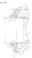
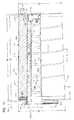
エアクリーナ用アセンブリ1に戻って、図8Aに注目すると、図5に類似する(図1〜図5のエアクリーナエアクリーナ用アセンブリ1の)ハウジング本体3の断面図を示す。但し、アクセスカバー4とエアフィルタ用カートリッジ40と安全エレメント41は、図示しない。また、図1に関連するラッチ8は、図8Aのハウジング本体3上には示していない。また、図8Aでは、吸引バルブ25(図1)は、図8のハウジング本体3上に配置していない。しかしながら、吸引バルブ25を使用するために配置する吸引開口部25aが見える。 Returning to the air
断面図の図8Aは、中央のカートリッジ支持体55の中央を通るものではなく、むしろわずかに中央から観察者に向かう方向であることが着目される。一方、図8Bは、類似の断面図であるが、中央のカートリッジ支持体55の中心を通って得られたものである。 It is noted that FIG. 8A in cross-sectional view does not pass through the center of the
一般に、図8A、8Bで見える構造(ハウジング本体3)は、1つの成形された構造のピースを含む。もちろん、代替物で組み立てることができる。通常の応用では、カートリッジ支持体55を含むハウジング本体3は、プラスチックから1つの一体ピースとして作られるだろう。 In general, the structure visible in FIGS. 8A and 8B (housing body 3) includes one molded structure piece. Of course, it can be assembled with alternatives. In typical applications, the
図8Aを参照して、カートリッジ支持体55上の端部部材55tに注目する。端部部材55tは、再び基部領域55bに対抗して配置される。端部部材55tは、出口12から開口端部10aに向かって離れる方向に突起する。実際に、図8Aのハウジング本体3に対して示された例示を含む、本明細書に記載されたいくつかの技術の応用において、端部部材55tの一部は、設置するとき、側壁10の開口端部10aを超えて、端部壁11と出口12に対向する方向に、すなわち、アクセスカバー4に向かう方向に、外側に突起することができる。 With reference to FIG. 8A, attention is paid to the end member 55 t on the
図示された例示に関して、端部部材55tは、第1(周辺リング)突起物125と第2(中央)突起物部材126の2つの突起物の部分を含む。それぞれの突起物部125と突起物部126は、ハウジング端部11から離れる方向で、隣接する端部部材55tの一部から軸方向に離れる位置で突起している。この文脈で「軸方向」によって、突起物は、長手方向の軸Xと一般的に同じ方向であることを意味する。示された例示に対して、第1(リング状)突起物125は、第2突起物126の周囲に伸びる外面くぼみ領域130によって第2(中央)突起物126から離れて配置されている。また、示された例示では、第2リング状突起物125は、連続していてかつ中央突起物126を外接している(取り囲んでいる)。 With respect to the illustrated example, the end member 55t includes two protrusion portions, a first (peripheral ring)
端部部材55tは、外面55xと内面55zを含む。くぼみ130は、外面55x中にある。 The end member 55t includes an
本明細書で、突起物が「軸方向」にある、または「軸方向に」伸びると言う場合、突起物は、必ず中央の長手方向の軸Xと完全に同じ直線上にあることを意味しない、むしろ、同じ長手方向に一般的にあることを意味する。 As used herein, when a projection is said to be “axial” or extend “axially”, it does not mean that the projection is necessarily exactly on the same straight line as the central longitudinal axis X. Rather, it generally means being in the same longitudinal direction.
図示された特別の例では、中央の突起物126は、円錐形状であり、軸Xに対して垂直な平面で円形の断面を持つ。より詳しくいうと、中央の突起物126は、円錐状の側壁126sを持ち、中央の突起物126は、先端126tに向かって内側にテーパ状となっている。しかしながら、先端126tは、円錐の先端がいくらか切られていて、必ずしも鋭くとがった先端かまたは完全に平らな端部となるわけではない。 In the particular example shown, the central protrusion 126 is conical and has a circular cross section in a plane perpendicular to the axis X. More specifically, the central protrusion 126 has a conical side wall 126s, and the central protrusion 126 is tapered inward toward the tip 126t. However, the tip 126t is somewhat truncated at the tip of the cone and is not necessarily a sharp pointed tip or a completely flat end.
図8Aを参照すると、得られた断面は、中央の突起物126を通過するものでなはく、むしろ中央の突起物126から観察者に向かって配置されるカートリッジ支持体55の一部を通っている断面であることが注目される。図8Aにおいて、いくつかの例示の寸法は、DA=332.6mm、DB=322.4mm、DE=174.5mm、DF=1.5mm半径、DG=63.8mm、DH=25.1mm、DJ=5mm半径、DK=3.2mm、DL=29.2mm、DI=25.3mmである。 Referring to FIG. 8A, the resulting cross-section does not pass through the central protrusion 126, but rather passes through a portion of the
図8Bに、図8Aに類似する第2の断面図を示すが、この例は、中央の突起物126の中央線を通って得られる図である。図8Bを参照すると、中央の突起物126は、端部11から軸方向に離れて突起する中空内部126iによって画定されることを理解することができる。また、図8Bを参照すると、第2のリング状突起物125は、端部11から軸方向に離れて突起する中空の内部125iを持つものとして理解することができる。 FIG. 8B shows a second cross-sectional view similar to FIG. 8A, but this example is taken through the center line of the central protrusion 126. With reference to FIG. 8B, it can be seen that the central protrusion 126 is defined by a hollow interior 126 i that protrudes axially away from the
より一般的な用語において、カートリッジ支持体端部55tは、外面55xと内面55zを持つ。例示のカートリッジ支持体端部55tは、外面55x、内面55zの両方に輪郭が描かれている。例示の形状は、くぼみ130によって第2のリング状突起物125から外面55xまで間隔をあけて配置されている中央の(例示では、円錐状の)突起物126がある形状である。内面55zは、表面131iによってくぼんだリング125iから間隔をおいて配置された中央の(例示で示される円錐の)外側突起物のくぼみ126iを持って画定され、表面131iが一般的に端部壁11に向かって突起しており、くぼみ125i、126iが端部壁11から離れる方向に突起しているという観測に基づく結果を残す。 In more general terms, the cartridge support end 55t has an
第2のリング状突起物125は、図8Bの外側の周辺表面125cを含む。示された例に対して、外側の周辺表面125cは、円形の周辺部を画定する滑らかで等高線でない表面であり、従って、一般的に円筒状形状を持つ。円筒状表面(外側の周辺表面)125cは、いくつかの応用では、端部壁11から離れる方向に延長部分中でわずかに内側にテーパ状となっているかもしれない。端部部材55tは、外側の周辺表面125cの基部端部から半径方向の外側に突起している周囲部の肩部55pを含む。外側の周辺表面125cは、使用されるとき、図5の安全エレメント41の端部キャップ91で開口部92を貫通して突起するように画定される。肩部55pは、オプションの安全エレメント41が取り付けられるとき、隣接する端部キャップ91を収容するような大きさで作られて配置されている。 The second ring-shaped
図8Bを参照すると、例示の寸法は、EA=523.2mm、EB=10mm、EC=40mm、ED=4°の円錐角度、EE=88.5mm、EF=110.6mm、EG=174.5mm、EH=294.6mmである。 Referring to FIG. 8B, exemplary dimensions are: EA = 523.2 mm, EB = 10 mm, EC = 40 mm, ED = 4 ° cone angle, EE = 88.5 mm, EF = 10.6 mm, EG = 174.5 mm EH = 294.6 mm.
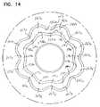
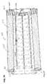
ここで、図9に注目する。図9に開いている端部10aに向かって得られるハウジング本体3(図8A、8B)の斜視図を示す。図9では、中央のカートリッジ支持体55が見える。特に、カートリッジ支持体55の端部部材55tを見ることができる。中央の突起物126は、くぼみ130によって取り囲まれているのを見ることができる。また、外側の円形壁125cと対抗する内壁125xとを含む外側の(第2のリング状)突起物125も見ることができる。 Attention is now directed to FIG. FIG. 9 shows a perspective view of the housing body 3 (FIGS. 8A and 8B) obtained toward the open end 10a. In FIG. 9, the
中央の突起物126、凹んでいる表面130、および第2のリング状突起物125は、端部部材55tの外面55x中の受け部くぼみ130xを集合的に画定する。受け部くぼみ130xは、以下で議論するように、取り付けの間に、第1エアフィルタ用カートリッジ40上の対応する突起物部材を収容するために配置されている。 The central protrusion 126, the recessed
一般的な用語で、端部部材55tの外面55xは、第1カートリッジ50と中央のカートリッジ支持体55との間の係合を提供する第1の突起物/受け部配置物の第1の部材を画定する。以下の記載から理解されるように、中央の突起物125、第2のリング状突起物126は、対応する第1のエアフィルタ用カートリッジ40の受け部部分に突起しており、第1エアフィルタ用カートリッジ40の部分は、カートリッジ支持体55上の受け部くぼみ130x中に突起している。 In general terms, the
図示された例示のアセンブリに対して、第2のリング状突起物125の内壁125xは、外側にカーブする凹状部134と内側に突起している凸状部分135を交互に持つ曲がりくねった表面形状を持つことを理解することができる。 For the exemplary assembly shown, the inner wall 125x of the second ring-shaped
本明細書で表面または壁の定義に関して「曲がりくねった」という用語が使用されているとき、円形の定義を画定する表面ではなく、むしろ表面に凸状と凹状とを交互に含む表面を言うことを意味する。 When the term “torky” is used herein for the definition of a surface or wall, it is not a surface that defines a circular definition, but rather a surface that includes alternating convex and concave surfaces. means.
特別の例示の曲がりくねった壁面(内壁)125xに対して、8つの凹部134は、中央突起物126の周囲の内壁125xの延長部分で、8つの凸部135によって分離されている。図示した例示に対するそれぞれの凹部134は、他の凹部と同じ形状と大きさである。それぞれの凸部135は、他の凸部と同じ形状と大きさに作られている。したがって、8つの花弁(ペタル)配置物は、内壁125xによって画定される。特別の例示の図示した曲がりくねった壁面(内壁)125xと花弁(ペタル)配置物に対して、8つ折りの回転対称性を持つ。すなわち、各花弁(ペタル)は、互いに同じ大きさと形状であり、花弁(ペタル)は、半径方向に間隔をあけて均等に配置されている。この文脈において、「8つ折りの回転対称性」という用語は、中央の軸の周りに回転することができる、8つの半径方向に均等に間隔をあけて配置されている配置であって、形状がそれ自体の形状と直線上に並ぶことができる配置を持つ形状の定義について言うために使用することができる。したがって、八角形は、8つ折りの回転対称性があり、一方、(対照的に)正方形では、4つ折りの回転対称性がある。 In contrast to the special exemplary winding wall (inner wall) 125 x, the eight recesses 134 are extensions of the inner wall 125 x around the central projection 126 and are separated by eight protrusions 135. Each recess 134 for the illustrated example is the same shape and size as the other recesses. Each convex part 135 is made in the same shape and size as other convex parts. Thus, eight petal arrangements are defined by the inner wall 125x. A special example of the illustrated winding wall (inner wall) 125x and petal arrangement has an eight-fold rotational symmetry. That is, each petal (petal) has the same size and shape as each other, and the petals (petals) are evenly spaced apart in the radial direction. In this context, the term “eight-fold rotational symmetry” refers to an eight radially evenly spaced arrangement that can rotate about a central axis and has the shape It can be used to say about the definition of a shape that has an arrangement that can be aligned with its own shape. Thus, octagons have eight-fold rotational symmetry, while (in contrast) squares have four-fold rotational symmetry.
より一般的な用語で、曲がりくねった表面125Xは、凸部と凹部を交互に持つ。通常は、少なくとも3つの凹部、通常は、少なくとも5つの凹部、通常は、6〜10個の凹部を持つ。 In more general terms, the serpentine surface 125X has convex and concave portions alternately. Usually it has at least 3 recesses, usually at least 5 recesses, usually 6-10 recesses.
ここで、図10を注目する。図10で図示するエアフィルタ用カートリッジ40は、エアクリーナ用アセンブリ1と別に示す。図10では、内部の詳細の理解を容易にするために、エアフィルタ用カートリッジ40の一部を断面で示す。 Attention is now directed to FIG. The
図10を参照すると、エアフィルタ用カートリッジ40は、媒体パック50を含む。媒体パック50は、空気のろ過用媒体51を含む。さまざまな種類の媒体をエアフィルタ用カートリッジ40に対して使用することができる。図示した特別の例示のろ過用媒体51は、内側のプリーツ先端部51pと外側のプリーツ先端部51oを持つひだ付き媒体を含む。フィルタ媒体51は、対向する第1の媒体端部51aおよび第2の媒体端部51bの間に伸びている。ひだ付き媒体51は、空気ろ過のために使用するさまざまなろ過用媒体の中から選択することができる。ろ過用媒体51に対する特別な効率と物理的な操作上の周辺部は、意図された応用に対する選択の問題である。一般に、知られているろ過用媒体を使用することができる。 Referring to FIG. 10, the
媒体パック50は、外側の周辺部50oと内側の周辺部50iを画定する。外側の周辺部50oは、外側のプリーツ先端部51oによって画定される。接着剤ビーズ140は、螺旋状パターンで外側のプリーツ先端部51oの周囲に伸びている。接着剤ビーズ140は、プリーツの間隔を維持するのを補助し、プリーツ支持体を提供する。 The
媒体パック50は、さらに、図5のインナーライナ71に対応するインナーライナ141を含む。インナーライナ141は、内側のプリーツ先端部51pに沿った媒体51の支持体ライナである。インナーライナ141は多孔性であり、プラスチックあるいは金属構造物を含むことができる。図示した特別の例示のカートリッジに対して、インナーライナ141は、複数の長手方向または軸方向の細長片141xと、交差するまたは半径方向のフープまたは細長片141cと、を含むプラスチック構造物である。 The
本明細書に記載された技術のいくつかの応用において、媒体パック51は、外側のライナ、例えば、プラスチックまたは金属ライナを含むことができる。 In some applications of the techniques described herein, the
媒体51の端部51aでは、媒体パック50(すなわち、ろ過用媒体51とインナ−ライナ141)は、端部キャップ66に埋め込まれている。また、端部キャップ66は、通常は、ハウジングのシール部材65と一体成形されて適所に鋳込まれた端部キャップ66aであり、示された例では、シール突起物70を含む。シールの支持体70aは、また、再びシール突起物70中に埋め込まれている。 At the end 51 a of the medium 51, the medium pack 50 (that is, the
ハウジングのシール部材70は、取り付けの間、図8Aの外壁97に対して圧縮によりポケット96中への挿入を容易にするために、階段状かテーパ状部70tを有するように構成された外側の(周囲部)のシール表面70oを含む。図5Bが参照される。 The
また図10を参照すると、図示された例ではプリフォーム81を含む端部キャップ80に注目する。この文脈の「プリフォーム」によって、例示の端部キャップ80は、(例えば、成形プラスチックから)形成され、次に、媒体パック50がその中に、接着剤と共に鉢植えにされて成形される。通常の物質は、固いポリウレタンで鉢植えに成形されるABS成形である。例示の端部キャップ80は、外側の周囲部リム150と外側の端部リング部151と中央のくぼみ152を含む。 Referring also to FIG. 10, attention is paid to the
エアフィルタ用カートリッジ40を組み立てるとき、媒体パック50は、外側の周囲部リム150と中央のくぼみ152との間に形成されるくぼみ155中に突起するように配置することによって、端部キャップ80中に鉢植え成形される。リム156は、成形の間、媒体パック50に対する円形の支柱リムとなる。 When assembling the
図10を参照すると、くぼみ155は、外側の端部リング151と対向する端部キャップ80の側部上に一般的に配置されることが着目される。 Referring to FIG. 10, it is noted that the
図10では、図示したサンプルシステムに対する例示の寸法は、FA=26.5mm、FB=529mm、FC=6mm、FD=522mm、FE=291.6mm、FF=176.4mm、FG=269mm、FH=76mm、およびFI=76mmである。 In FIG. 10, exemplary dimensions for the illustrated sample system are FA = 26.5 mm, FB = 529 mm, FC = 6 mm, FD = 522 mm, FE = 291.6 mm, FF = 176.4 mm, FG = 269 mm, FH = 76 mm and FI = 76 mm.
図10に図示された例示のエアフィルタ用カートリッジ40に対して、外側のプリーツ先端部51oは、一般的に円錐形状を形成し、媒体の端部51aから媒体の端部51bに下向方向にテーパ状に延長している。本明細書に記載された原理は、円筒状形状および円錐状形状を含むさまざまな形状の配置物中で実施することができる。円錐形状が使用される場合、テーパの角度は、通常は、少なくとも0.5°の角度であり、通常は、少なくとも1°であり、しばしば、1〜4°の範囲の角度である。 With respect to the
好ましくは、エアフィルタ用カートリッジ40が円錐状である場合、媒体パック51に対する円錐状のテーパは、図5の支持体で示される円錐状のテーパ形状よりもテーパ角度が小さい。 Preferably, when the
ここで、図11を着目すると、図10で示される端部キャップ80の拡大した断面図を示す。図11では、端部キャップ80の断面図は、図10の媒体パック50に固定される前の端部キャップ80のみを見ることができる。 Here, focusing on FIG. 11, an enlarged cross-sectional view of the
図11を参照すると、中央のくぼみの部分152は、外側の周囲壁160と端部壁161の特徴を含む。外側の周囲壁160は、一般に、図10の媒体パック50の内部60中に突起している。媒体パック50の内部50iに隣接して、または、媒体パック50の内部50iからわずかに間隔をあけて配置される内壁161は、一般に、内部60を横切って伸びている。 Referring to FIG. 11, the central indented portion 152 includes features of an outer
端部壁161は、内面161yと外面161xとを含む。内面161yは、一般に、エアフィルタ用カートリッジ40の端部キャップ66に向かっている。外面161xは、一般に、内面161yに対抗しており、端部キャップ66から離れる方向に向いている。 The
第1の内面161yは、外側のリング部162を含む。円形の軸方向の外側に突起している受け部ポケットまたはリング状くぼみまたは受け部165は、外側のリング部162から半径方向の内側に提供され、外壁部166と内壁部167と端部壁部168によって画定される。この文脈の「軸方向の外側に突起している」によって、リング状受け部165は、一般に、図8Aの対抗する端部キャップ66の方向に突起していることを意味する。リング状くぼみ(受け部)165は、取り付けの間に、中央のカートリッジ支持体端部55t上のリング状突起物125をその中に突起して収容するような大きさと形状に作られている。リング状くぼみ(受け部)165は、通常は、中央の軸Xの周囲の延長部分中に連続している。図16を参照すると、中央部4cは、周辺部4pの中央点上に必ずしも配置されるわけではなく、偏心的に配置されて図示されていることが注目される。 The first inner surface 161 y includes an
内壁部167は、通常は、図9の内側壁125xと係合する、外部に向いた凸状部と外部に向いた凹状(または、内部に向いた凸状)部とが交互にあらわれる曲がりくねった形状を持つ。すなわち、図9の曲がりくねった表面(内側壁)125xは、表面対表面の係合により、図11の曲がりくねった表面167iの周囲に押されて、曲がりくねった表面167iと係合する。曲がりくねった表面(壁)167i上の外側に突起した花弁(ペタル)部を収容する表面(内側壁)125x上の花弁(ペタル)構造の結果として、係合が起こると、端部キャップ80は、従って、エアフィルタ用カートリッジ40は、中央のカートリッジ支持体55に対して容易に回転しないであろう。 The
言い換えると、エアフィルタ用カートリッジ40がカートリッジ支持体55の上方に設置されると、カートリッジ支持体55の周囲のエアフィルタ用カートリッジ40の回転の動きは、曲がりくねった内側壁125xの花弁(ペタル)形状と、曲がりくねった表面167iの花弁(ペタル)形状との間の干渉の相互作用の結果として、禁止される。これらの表面は、一緒になって、エアフィルタ用カートリッジ40と中央のカートリッジ支持体55との間で回転しない係合を形成する。このことは、エアフィルタ用カートリッジ40が、カートリッジ支持体55に対して選択された回転の配置の1つだけに配置することができることを保障することを補助する。8つの花弁(ペタル)が、8つの折り曲げ対称を持つ内側壁125x、167iのそれぞれで存在するとき、8つの回転位置が可能である。 In other words, when the
内壁部167の半径方向の内部に間隔をあけて配置された内面161yは、中央の外側突起物170を含む。中央の外側突起物170は、外側の端部171と、側壁173とを含む。図示した例示では、側壁173は、一般に、円錐状であり、中央の軸Xを取り囲んでいる。 The inner surface 161 y that is spaced apart from the inside of the
また図11を参照すると、エアフィルタ用カートリッジ40がハウジング2中に取り付けられるとき、中央の外側突起物170は、その中に突起する中央のカートリッジ支持体55の端部55t上の中央の突起物126を収容する大きさと形状に作られている。 Referring also to FIG. 11, when the
中央の突起物170は、さらに、内面176を持つ基部175を含む。一般に、基部175は、取り付けの間に、図9の受け部くぼみ130x中に突起する。 The
ここで、図11の端部壁の外面161xに着目する。外面161xは、内壁部167と基部175との間に、その中に画定される受け溝180を含む。内壁部(表面)167と基部175の外面167oと外面175oとは、それぞれ、一般に曲がりくねったものであり、曲がりくねった受け溝180を形成する。曲がりくねった受け溝180は、外部に突起する凹部と内部に突起する凸部とが交互に現れることによって画定される壁(外面)167oに沿った外側に曲がりくねった表面と、外部に突起する凸部と、内部に突起する凹部によって画定される壁175oに沿った内面とを持つ。通常は、内壁部167の外側に突起する凹部は、基部(壁)175の外側に突起する凸部と半径方向に一直線上に並んでおり、かつ、内壁部167の内側に突起する凸部は、基部(壁)175の内側に突起する凹部と半径方向に一直線上に並んでいて、曲がりくねった受け溝180を形成する。受け溝180は、以下で議論するように、アクセスカバー4上の突起物のための受け溝である。 Here, attention is paid to the
図11において、例示の寸法は、GA=20mm、GB=2mm、GC=2mm、GD=10°の角度、GE=269mm、GF=206mm、GG=152mm、GH=97.5mm、GI=26mm、GJ=46.5mm、GK=144.2mm、GL=23.8mm、GM=2mmの半径、GN=2mm、GO=8.1mm、およびGP=46.4mmである。 In FIG. 11, exemplary dimensions are GA = 20 mm, GB = 2 mm, GC = 2 mm, GD = 10 ° angle, GE = 269 mm, GF = 206 mm, GG = 152 mm, GH = 97.5 mm, GI = 26 mm, GJ = 46.5 mm, GK = 144.2 mm, GL = 23.8 mm, GM = 2 mm radius, GN = 2 mm, GO = 8.1 mm, and GP = 46.4 mm.
通常の例では、受け溝180は、例えば、図12のXXで計測されるように、受け溝によって取り囲まれる空間または領域を横切る最小の内部寸法は、少なくとも10mm、通常は、少なくとも15mm、しばしば、少なくとも20mm、例えば、通常は、20〜40mmの範囲である。 In a typical example, the receiving
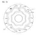
ここで、図12に示す外面161xに向かう方向のプリフォーム81の概略的な外側の平面図に注目する。中央の受け溝180が見える。図12では、中央の受け溝180は、簡略化した概要図で示されることが注目される。図11では、壁(外面)167o、壁175oの表面は、受け溝180の先端180tから外側に互いにテーパ状に離れるように見ることができる。図12では、テーパ状に離れることを示すための等高線は示されていない。 Here, attention is paid to the schematic outer plan view of the preform 81 in the direction toward the
図13には、内面161yに向かう端部キャップ80の内面の端面図が示されている。 FIG. 13 shows an end view of the inner surface of the
ここで、図12の一部の部分図である図14に注目する。中央の受け溝180は、壁(外面)167oと壁175oとの間に見ることができる。壁167oは、外に向いた凹部167xと内部に突起する凸部167yとを持つ曲がりくねった表面を画定することを理解することができる。内面(壁)175oは、外に突起する凸部175xと内部に突起する凹部175yとを持つ曲がりくねった表面を画定することを理解することができる。一般に、凹部167xは、凸部175xと一直線上に並んでおり、凹部175yは、凸部167yと直線上に並んでいる。結果として曲がりくねった溝180が得られる。通常の好ましい応用では、中央の受け溝180は、連続する円形の突起物が中央の受け溝180に突起しないでむしろ中央の受け溝180中に伸びている連続した突起物が、好ましくは曲がりくねった形状を持つような大きさと形状に作られている。 Attention is now directed to FIG. 14, which is a partial view of FIG. The
図15に、内面161yの部分拡大図を提供する。凸部167eと凹部167fを持つ内面167iを見ることができる。この内面167iは、前に説明したように、カートリッジ支持体55状の表面(内側壁)125xと係合するように構成されている。 FIG. 15 provides a partially enlarged view of the inner surface 161y. An inner surface 167i having a
ここで、図16に注目する。図16は、アクセスカバー4の外側の平面図である。すなわち、図16の図は、図1の矢印4xの一般的な方向である。アクセスカバー4は、中央部4cと周囲部リム4pと外側端部の表面4bを含む。 Attention is now directed to FIG. FIG. 16 is a plan view of the outside of the
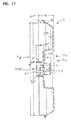
図17を参照すると、アクセスカバー4は、一般に、図16の線17-17に沿って得られる断面図で示される。アクセスカバー4は、ハウジング2の内部に面している内面4yと、対向する外面4zとを含む。図17を参照すると、周囲部リム4pで、アクセスカバー4は、周囲部リム部分200を含む。周囲部リム部分200は、図5の取り付けの間、側壁10と係合するような大きさに作られて配置されている。 Referring to FIG. 17, the
図17を参照すると、内面4yは、取り付けの間にエアフィルタ用カートリッジ40と係合する表面を含む。内面4yは、外側のリング部201を含む。外側のリング部201は、図5の取り付けの間に媒体パック50の端部50bと重なる。また、内部に突起する壁202は、領域(リング部)201から半径方向の内部にある。一般に、内部に突起する壁202は、取り付けの間、エアフィルタ用カートリッジ40の内部に突起する。言い換えると、内部に突起する壁202は、一般に、取り付けの間、媒体パック50の端部50bによって取り囲まれている。 Referring to FIG. 17, the inner surface 4y includes a surface that engages the
突起物210は、内部に突起する壁202から半径方向の内部の表面(内面)4y上に提供される。突起物210は、取り付けの間、図11の中央の受け溝180に収容される大きさと形状で突起するように作られている。代替手段は可能であるが、突起物210は、通常は、軸Xの周囲の延長部分内に連続している。また、突起物210は、通常は、中身が詰まっており(中空でない)、通常は、貫通する開口部を含んでいない。 The
突起物210は、半径方向の外面211と半径方向の内面212を持つ。示された例に対して、外面211は、一般に、曲がりくねっており、外側に凸部と内部に凹部を交互に現すものを有する。また、内面(内壁)212は、一般に、曲がりくねっており、対応する内部に突起する凸部領域と外側に突起する凹部領域とを有し、それらの領域は、互いに交代するものである。外側に突起する壁(外面)211の凸部は、内部に突起する壁212の凹部と半径方向に一直線上に並んでおり、内部に突起する壁(外面)211の凹部は、内部に突起する壁212の凸部と一直線上に並んでいる。 The
軸Xの周囲の延長部で突起物210に対する曲がりくねった形状により、壁210は、図11の曲がりくねった受け溝180内に収容されるような大きさと形状に作られている。 Due to the serpentine shape with respect to the
内面212の対抗する部分の間の突起物210を横切る寸法は、通常は、少なくとも10mmであり、普通は、少なくとも15mmであり、しばしば、少なくとも20mmであり、例えば、20〜40mmである。この寸法は、図17の寸法XXXに対応するものである。 The dimension across the
中央の受け溝180に対する曲がりくねった突起物により、回転しない係合が得られる。すなわち、適切な大きさに作られたエアフィルタ用カートリッジ40とアクセスカバー4は、突起物210がいったん中央の受け溝180中に伸びると、互いに回転が禁止される。アクセスカバー4は、エアフィルタ用カートリッジ40がカートリッジ支持体55上にあらかじめ配置されると、突起物210が中央の受け溝180に伸びるようなアクセスカバー4の回転の配置を確実にするように、ハウジングの側壁10に対して選択された回転の配置で取り付けられるように割り出すことができる。 A non-rotating engagement is obtained by the tortuous projections on the
また図17を参照すると、壁(突起物)210は、中央の外側の突起物220を取り囲こみ、図2の突起物33を形成する。内面4y中の中央の外側の突起物220は、一般に、図5の壁11から離れる方向に伸びており、図11の突起物170のために受け部空間221を画定する。 Referring also to FIG. 17, the wall (projection) 210 surrounds the central outer projection 220 and forms the
図18に、内面4yの一部の部分平面図を提供する。突起物210は、外面211、内面212とともに見ることができる。一般に、外面211、内面212は、一般的に図17の先端21Otに向かう方向の延長部分で互いに集中し、先端から互いに離れる方向の延長部分で発散することが注目される。 FIG. 18 provides a partial plan view of a portion of the inner surface 4y. The
図18では、補強リブ230を内面4y上に見ることができる。 In FIG. 18, the reinforcing
図19では、壁(突起物)210の概略的な拡大図が提供され、輪郭加工か曲がりくねった形状の理解を外面211、内面212に容易にするためにの拡大して、図式の図を提供する。 In FIG. 19, a schematic enlarged view of the wall (projection) 210 is provided, providing an enlarged, schematic view to facilitate understanding of the contoured or serpentine shape on the outer surface 211,
図19を参照すると、突起物210の外面211は、曲がりくねった形状を持つことが理解できる。曲がりくねった形状は、内部に向いた凹部211xと外側に突起する凸部211yとを交互に含む。内面212もまた曲がりくねった形状であることが理解できる。曲がりくねった形状は、外側に突起する凹部212yと内部に突起する凸部212xを持つ。各部(内面の凸部)212xは、半径方向に部分(外面の凹部)211xと一直線上に配置され、各部(内面の凹部)212yは、半径方向に部分(外面の凸部)211yと一直線上に配置される。その結果として、壁(突起物)210は、中央215の周りに8つの折りたたみの半径方向の対称を持つ、8花弁(ペタル)形状を持つ。 Referring to FIG. 19, it can be understood that the outer surface 211 of the
図17に戻って参照すると、例示の寸法は、IA=54.5mm、IB=28mm、IC=24mm、ID=329.9mm、IF=327mmである。 Referring back to FIG. 17, exemplary dimensions are IA = 54.5 mm, IB = 28 mm, IC = 24 mm, ID = 329.9 mm, IF = 327 mm.
II.中央のカートリッジ支持体55、第1カートリッジ40、アクセスカバー4の有利な相互作用の配置
上記の図の概説から(ハウジング本体3中の)中央のカートリッジ支持体55と、第1カートリッジ40と、アクセスカバー4との間の有利な相互作用を理解することができる。それらの特徴は、一般的に以下の通りである。II. Arrangement of advantageous interaction of the
第1カートリッジ40は、カートリッジ支持体55と回転しない相互作用で配置される。この回転しない配置は、図5Aに図示されるように、端部キャップ80の内面161y上の構造と係合している端部55t(図8A)の外面55x上の構造から得られる。特に、回転しないの相互作用は、端部キャップ80の表面(内面)161yで外側に向いている曲がりくねった壁167iの周囲に伸びて係合しているリング状突起物125の曲がりくねった内壁125xから得られる。記載されたように、曲がりくねった係合により、カートリッジ40を取り付けるとき、カートリッジ40は、中央のカートリッジ支持体55に対して複数の選択された回転の配置のうちの1つの配置で容易に配置することができる。 The
図示された特別の例示のシステムでは、凸部と凹部が交互に現れる曲がりくねった形状により、中央のカートリッジ支持体55上のカートリッジ40に対して8つの回転の配置がある。代替の数は可能である。 In the particular exemplary system shown, there is an eight rotation arrangement relative to the
したがって、特に、カートリッジ40と支持体55との間の回転しない係合は、カートリッジ40がアクセスカバー4との係合のためにある予め選択された配置のうちの1つの配置だけで固定されるのを確実にする。 Thus, in particular, the non-rotating engagement between the
アクセスカバー4は、端部ピースまたは端部キャップ80の外面161xで画定される溝180中に伸びている突起物210を含む。溝180中への突起物210の突起は、アクセスカバー4が、好ましくないレベルの端部50bの片持ちばりの端部の動き、すなわち、隣接する端部ピース80に対して、カートリッジ40を支持するのを提供する。すなわち、カートリッジ端部50bは、図5Aで上下または観察者に向かう方向と離れる方向(in-out motion)の動きまたはそれらの混合の動きの好ましくない動きをしないだろう。許容される動きの量は、溝180の幅と相対的な突起物210の厚さに依存するだろう。通常は、それらは、組立ての容易さを可能にするすきまの量である最小の動きだけ可能にするように選択される。
次に、図示された例示に対して、カートリッジ40は、好ましくないレベルの片持ちばりの動きに対して、媒体パック端部50bを取り囲む周辺領域30と突起物200とを除いてアクセスカバー4の部分が無い状態で、すなわち、カートリッジ40、すなわち媒体パック50とまた係合する媒体パック50bを取り囲んでいいる部分が無い状態で、媒体パックの端部50bで支持することが着目される。言い換えると、カートリッジ40は、カートリッジ40の外部の周囲で支持体によって端部50bで支持されておらず、むしろ内部のみ支持されている。 Next, for the illustrated example, the
支持体に対して、好ましくは、突起物210は、少なくとも5mmの距離で、通常は、少なくとも12mmの距離で、通常は、15〜30mmの範囲で伸びている。 For the support, preferably the
好ましくは、溝180は、延長部分の深さに沿って、10mm未満の幅、通常は、9mm未満の幅、通常は、4〜7mmの範囲の幅を持つ。好ましくは、溝180は、少なくとも6mmの深さ、通常は、少なくとも12mmの深さ、通常は12〜25mmの範囲の深さである。 Preferably, the
通常の応用では、溝180の半径方向の外側の壁167oは、媒体パック50から少なくとも20mmの位置に、通常は、少なくとも30mmの位置に配置される。 In typical applications, the radially outer wall 167o of the
好ましくは、突起物210の厚さは、その長さに沿って、少なくとも1mmの厚さ、通常は、少なくとも1.5mmの厚さ、普通は1.5〜4mmの範囲の厚さである。 Preferably, the
これらの例示の寸法により、突起物210と溝180とを含む突起物/受け部配置物は、片持ばりの動きに対してカートリッジ40を保護することが便利である。 With these exemplary dimensions, it is convenient for a protrusion / receiver
さらに、突起物210の曲がりくねった外面211は、アクセスカバー4とカートリッジ40間の相対的な回転を抑制しながら、突起物167上の表面167oと係合する。実際は、表面(内側壁)125xと表面211との間の壁167ではさむことによって、総合的に回転しない配置が形成される。 Further, the winding outer surface 211 of the
上記説明した相互作用は、一旦設置されると、片持ちばりの動きに対して媒体パックの端部50bでカートリッジ40に対する支持と、回転運動に対するカートリッジ40の支持を提供する。 Once installed, the interaction described above provides support for the
さらに、本明細書に記載されたような配置物は、エアクリーナ用アセンブリ1に対して、取り付けられたカートリッジ40が、選択された好ましいカートリッジ40であることを確実にすることを補助する。図5Aを参照すると、アクセスカバー4中の突起物33は、カートリッジ40中の突起物170に対する受け部33rとして作用する。カートリッジ40の上の突起物170は、内面の表面に沿って、支持体55上の突起物126に対する受け部として作用する。これらの特徴は、溝180中に収容された突起物210と、(中央のカートリッジ支持体55上のリング状突起物125と突起物126との間で受け部130内に収容され、溝180を画定する)突起物180pとが、使用時に、ハウジング本体2の内部2iで、不適切または好ましくないカートリッジ40の設置を禁止する配置を形成することと組み合わされる。これを容易にするために、好ましくは、突起物170は、少なくとも10mmの距離で、普通は、15mm〜50mmの範囲の距離で、受け部33r中に伸びており、突起物126は、少なくとも10mmの距離で、普通は15〜50mmの距離で、受け部170中に伸びている。 Further, the arrangement as described herein helps the air
通常は、図11の壁167、166の間に形成された受け溝168は、少なくとも10mmの幅、通常は、少なくとも20mmの幅であり、しばしば、20〜30mmの範囲の幅である。受け溝168は、通常は、幅40mmを超えない。 Typically, the receiving groove 168 formed between the
記載された様々な相互作用は、カートリッジ40がハウジング2中に適切に取り付けられること、特に、カートリッジ40が取り付けられたとき、ハウジングの中央のカートリッジ支持体55との係合が起こること、を確実にすることを補助することが注目される。このことは、カートリッジ40が、ハウジング本体3中で、長さに沿って適切に一直線上に並べられることを確実にするのを補助する。アクセスカバー4が配置されるとき、更なる係合が起こり、再び、カートリッジ40がハウジング本体2中でアクセスXの周りで長手方向に適切に一直線上に並べられることを確実にする。 The various interactions described ensure that the
また、アクセスカバー4は、カートリッジ40が所定の位置で適切にシールされない場合には、容易にハウジング側壁10中に設置されないだろう。 Also, the
III.オプションの安全エレメント41
ここで図5Aを参照して、オプションの安全エレメント41の取り付けを再検討する。端部ピース91は、リング状突起物125の壁125cの上に適合する内部の開口部92を持つ。カートリッジ端部ピース80は、240で示される内部に向けられたリング状突起物を含む。リング状突起物240は、いったん取り付けられると、安全エレメント41がアクセスカバー4に向かう移動を禁止するように端部ピース91の端部91eに係合する。III.
Referring now to FIG. 5A, the installation of the
図示された例示の安全エレメント41は、端部91から対向する端部で端部キャップを含まない。むしろ、図示された例示では円錐形状であり、媒体41は、ぴったり合った係合が得らるまで、円錐状の支持体の上で押される。 The illustrated
図示された構成物は、オプションの安全カートリッジ41が存在するか否かにかかわらず、内部のカートリッジ支持体55によってカートリッジ40の支持体を提供する。このことは、安全フィルタ41がオプションに存在するかしないかを使用中に可能するので、有利である。 The illustrated arrangement provides support for the
IV.第3の実施例 図20〜31
図20〜31に、本開示の原理の更なる代替の実施例を示す。作動の一般原理は、同じままで残っているが、しかしながら、ある特別の詳細は、以下に説明するように変更されている。IV. Third Example FIGS.
20-31 illustrate further alternative embodiments of the principles of the present disclosure. The general principle of operation remains the same, however, certain special details have been changed as described below.
図20を参照すると、参照番号301は、エアクリーナ用アセンブリを一般的に示す。エアクリーナ用アセンブリ301は、ハウジング本体303とアクセスカバー304を含むハウジング302を含む。アクセスカバー304は、ラッチ308を含む接続配置物307によってハウジング本体303上の適所に固定される。図21を参照すると、ハウジング本体は、アクセスカバー304が取り付けられる第1の開いている端部310aを持つ側壁310を含む。ハウジング側壁310は、第1の端部310aに対向して第2の端部310bを含む。第2の端部310bは、その上にハウジング端部壁311を持ち、その中を通る空気流の開口部312を持つ。 Referring to FIG. 20,
図21の図には、ラッチ308を取り付けずに示してることが注目される。 It is noted that the view of FIG. 21 is shown without the
図20を参照すると、エアクリーナ301は、入口アセンブリ316から空気を受ける空気取入口の開口配置物315を含む。 Referring to FIG. 20, the
図21を参照すると、アセンブリは、取付用パッド321と吸引バルブ配置物325とを含む。 Referring to FIG. 21, the assembly includes a mounting
また、アセンブリ301は、カートリッジ支持体355と安全カートリッジ341とを含む。 The
従って、これまで記載したコンポーネントは、第1実施例と第2実施例に関して前に記載したのと一般的に同じであり得る。この文脈において、同じように特徴付けられた特徴は、同じような機能と動作を持つ。 Thus, the components described so far may be generally the same as described previously with respect to the first and second embodiments. In this context, similarly characterized features have similar functions and operations.
実際に、エアクリーナ用アセンブリ301に対するエアクリーナのハウジング本体303とアクセスカバー304は、本原理の特別な応用に依存する図6のアセンブリ301に対して、または、図1のアセンブリ1に対してと同じであり得る。 In fact, the air
また図21を参照すると、カートリッジ340がハウジング302の内部302i内に取り付けられて示されている。カートリッジ340は、記載されたような変更を除いては、図5のカートリッジ40と同じであり得る。特に、図21の端部キャップ366は、図5の端部キャップ66から変更されており、端部キャップ367は、端部キャップ80から変更されている。 Referring also to FIG. 21, the
図22を参照すると、端部キャップ366は、適所に成形されており、端部キャップ366の上に一体成形されたシール突起物370を含む。シール突起物370は、ポケット396の壁397に対して係合してシールしている。 Referring to FIG. 22, the
端部キャップ366で外側に向いた周囲部の半径方向シールを形成するために、壁397に対してシール突起物370の圧力は、突起物370中に埋め込まれたシールの支持体部材410によって提供される。突起物410は、図29〜図31に関連して以下でさらに説明する。 The pressure of the seal protrusion 370 against the
図23に、ハウジング本体303を示す。支持体355と支持体端部355tは、図1〜5の実施例と関連して前に説明されたのと一般的に類似の特徴に類似することができることを理解することができる。 FIG. 23 shows the
したがって、支持体端部355tは、リング状突起物425と中央の突起物426とを含む。 Therefore, the support body end portion 355t includes a ring-shaped protrusion 425 and a central protrusion 426.
図24に、図23の拡大部分断面図を示す。ここで、対向する壁397と壁395を持つポケット396を見ることができる。 FIG. 24 shows an enlarged partial sectional view of FIG. Here, a
図25に、アクセスカバーで304が取り外された状態のハウジング本体303の端面図を示す。 FIG. 25 shows an end view of the
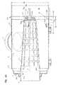
図26に、カートリッジ340の断面図を示す。カートリッジ340は、媒体パック350を含む。媒体パック350は、開いている内部360を画定するためにインナーライナ352を取り囲んでいる媒体351を含む。インナーライナ352は、端部キャップ366と端部キャップ367との間に伸びている。実施例に対して、端部キャップ366と端部キャップ367は、どちらも適所に成形されており、それぞれは、成形された発泡した圧縮性ポリウレタンを通常は含んでいる。インナーライナ352は、埋め込まれて、端部キャップ366と端部キャップ367の間に伸びている。シール突起物370は、端部キャップ366の一部として一体に成形されている。 FIG. 26 shows a cross-sectional view of the
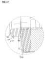
図27は、図26の部分拡大断面図である。ここで、突起物370は、残りの部分と一体成形されている端部キャップ366を見ることができる。また、突起物410、埋め込まれた突起物370を見ることができる。突起物410は、インナーライナ352の一部であり、ハウジング302中にカートリッジ340の取り付けの間、シール面370sに沿ってシール部材370に対する支持体を提供するであろう。 27 is a partially enlarged cross-sectional view of FIG. Here, the protrusion 370 can see the
ここで、アクセスカバー304を示す図28に注目する。アクセスカバー304は、曲がりくねった外面411と曲がりくねった内面412とを持つ突起物410を含むことを理解することができる。アクセスカバー304は、図17のアクセスカバー4と同じであり得る。 Attention is now directed to FIG. 28 showing the
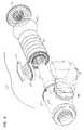
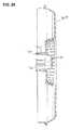
ここで、インナーライナ352を示す図29に注目する。インナーライナ352は、端部451と端部452の間で伸びている媒体の支持体部450を含むことが理解できる。媒体の支持体部450は、長手方向の細長片455と、空気流に対する開口457を画定する交差する細長片456を含む。 Attention is now directed to FIG. 29 showing the
451で、媒体の支持体部450は、残りの部分450と一体となっているシールの支持体領域410を含む。シールの支持体領域410は、媒体の支持体部450の直接隣接する部分450aより大きい直径の領域を含む。したがって、外側に伸びている肩部410bは、領域410と媒体の支持体部450との間の領域410に隣接している。領域410は、そこを貫通する複数の開口410aを含む。端部キャップ366が埋め込まれるとき、端部キャップ366の成形の間、端部キャップ物質は、図27の突起物370内の支持体410を巻き込みながら、開口410aを通って流れることができる。端部451でフレームワーク(枠組み)は、シールの支持体を提供するだろう。 At 451, the
肩部410bは、媒体の支持体450の周囲に配置されたときに、媒体351に対して媒体の停止を提供することが注目される。すなわち、肩部410bは、組立ての間、媒体351の便利な支持体に対して媒体351の端部を横切って伸びるであろう。 It is noted that the shoulder 410b provides a media stop for the
端部452で、端部キャップ367中に埋め込まれている延長部分470が示されている。端部452を横切って伸びており、支持体470によって取り囲まれている端部ピース490が提供される。端部ピース490は、図11の端部キャップ151の中央部分に類似する構成を持つ。従って、曲がりくねった受け溝500と中央の突起物受け部401が存在する。 At the
したがって、端部キャップ367は、図27の適所に成形された外側のリング部分を含み、かつ中央部分481が、片持ちばりでなくかつ回転しない支持体のための適切な構成を持つプリフォームされた物質を含む複合材料の端部キャップを有することを理解することができる。この例示では、中央部分481はインナーライナ352と一体成形されている。 Thus, the
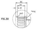
図30に、図29の部分拡大図を示す。図31に支持体352の斜視図を示す。 FIG. 30 shows a partially enlarged view of FIG. FIG. 31 is a perspective view of the
図29〜図31では、例示の寸法は、ZA=180mm、ZB=154.1mm、ZC=9.5mm、ZD=4.5mm、ZE=203.4mm、ZF=1mmである。図30において、ZG=29.5mm、ZH=19.32mm、ZI=4.5mmである。 In FIGS. 29-31, exemplary dimensions are ZA = 180 mm, ZB = 154.1 mm, ZC = 9.5 mm, ZD = 4.5 mm, ZE = 203.4 mm, ZF = 1 mm. In FIG. 30, ZG = 29.5 mm, ZH = 19.32 mm, and ZI = 4.5 mm.
V.結論の総括
本明細書では、前の記載と示した図により、エアクリーナ用アセンブリとコンポーネントを詳細に説明し図示した。エアクリーナ用アセンブリまたはコンポーネントは、本開示の原理に基づくいくつかの利益を得るために、本明細書に記載されて特徴付けられた特徴の全てを含む必要性は特に全くない。V. Conclusion Summary In this specification, the air cleaner assembly and components have been described and illustrated in detail with reference to the previous description and illustrated figures. There is no particular need for an air cleaner assembly or component to include all of the features described and characterized herein to obtain several benefits based on the principles of the present disclosure.
本開示の1つの態様によると、エアクリーナ用アセンブリを提供する。エアクリーナ用アセンブリは、ハウジングと、点検可能なフィルタカートリッジとを含む。フィルタカートリッジは、ハウジングと点検可能なフィルタカートリッジとに損傷与えないで、ハウジング内に配置可能であり、かつハウジングから取り外し可能である。また、オプションの安全エレメントが提供される。 According to one aspect of the present disclosure, an air cleaner assembly is provided. The air cleaner assembly includes a housing and a serviceable filter cartridge. The filter cartridge can be placed in and removed from the housing without damaging the housing and the serviceable filter cartridge. An optional safety element is also provided.
一般に、ハウジングは、ハウジング本体と、アクセスカバーとを含む。ハウジング本体は、側壁と、中央のカートリッジ支持体とを含む。側壁は、一般的に、ハウジング本体の内部を画定する。ハウジング本体は、通常は、そこを通る空気流れの開口部を持つ端部壁と、端部壁に対向する開いている端部とを含む。中央のカートリッジ支持体は、ハウジング本体の開いている端部に向かう方向に、空気流れの開口部を取り囲んでいる支持体基部から伸びている。 Generally, the housing includes a housing body and an access cover. The housing body includes a side wall and a central cartridge support. The side wall generally defines the interior of the housing body. The housing body typically includes an end wall having an opening for air flow therethrough and an open end opposite the end wall. A central cartridge support extends from a support base surrounding the air flow opening in a direction toward the open end of the housing body.
一般的に、ハウジングの端部壁と開いている端部とは、ハウジングの側壁の対向する端部にある。 Generally, the end wall and the open end of the housing are at opposite ends of the side wall of the housing.
通常の配置物では、ハウジングは、空気入口の配置物を含む。図示された例では、空気入口の配置物は、ハウジング本体の側壁中にある空気流の開口部である。したがって、通常の応用では、側壁中の空気流の開口部は、使用の間、収容部のフィルタカートリッジに対して外から中への流れ(out-to-in flow)に対する入口の流れ開口部であり、端部壁の空気流の開口部は、出口開口部である。しかしながら、本明細書に記載された原理の多くは、所望であれば、いくつかの応用において、中から外への流れ(in-to-out flow)(反対の流れ)に対して使用することができることが注目される。 In a typical arrangement, the housing includes an air inlet arrangement. In the illustrated example, the air inlet arrangement is an airflow opening in the side wall of the housing body. Thus, in normal applications, the air flow opening in the sidewall is the inlet flow opening for out-to-in flow with respect to the filter cartridge in the housing during use. Yes, the air flow opening in the end wall is the outlet opening. However, many of the principles described herein may be used for in-to-out flow (opposite flow) in some applications, if desired. It is noticed that you can.
中央のカートリッジ支持体は、基部から離れる方向に支持体端部を含む。基部から離れる方向の支持体端部は、第2の(中央)の突起物から間隔をあけて配置されている第1の(リング状)突起物を含み、それらの間で受け部空間を画定する。図示された特別の例示のシステムに対し、第1の突起物は、外側のリング状突起物であり、第2の突起物(中央の突起物である)の周囲に(例示では、連続的に)伸びている。第1のリング状突起物と第2の中央の突起物とは、一般的に、支持体基部と端部壁とから離れる方向に一般的に突起する。 The central cartridge support includes a support end in a direction away from the base. The support end in a direction away from the base includes a first (ring-shaped) protrusion spaced from a second (center) protrusion and defines a receiving space therebetween. To do. For the particular exemplary system shown, the first protrusion is an outer ring-shaped protrusion and around the second protrusion (which is the central protrusion) (in the example, continuously). ) It is growing. The first ring-shaped protrusion and the second central protrusion generally protrude in a direction away from the support base and the end wall.
通常は、外側の第1のリング状突起物は、支持体端部にすぐ隣接する部分から、少なくとも5mmの長さ、通常は7mmの長さ、しばしば、7〜25mmの範囲内の量の長さで伸びており、中央の突起物は、支持体端部のすぐに隣接している部分から、少なくとも10mmの長さ、通常は5mmの長さ、しばしば、18〜40mmの範囲内の量の長さで伸びている。 Typically, the outer first ring-shaped projection is at least 5 mm long, usually 7 mm long, often in an amount in the range 7-25 mm from the portion immediately adjacent to the support edge. The central protrusion is at least 10 mm long, usually 5 mm long, often in an amount in the range 18-40 mm from the immediately adjacent portion of the support edge. It grows in length.
示された例では、第2の中央の突起物は、側壁の開いている端部から外側方向に突起する。 In the example shown, the second central projection projects outward from the open end of the sidewall.
点検可能な第1のエアフィルタ用第1カートリッジは、ハウジング本体内部に配置される。エアフィルタ用カートリッジは、開いているフィルタ内部を取り囲こみ、第1端部キャップと第2端部キャップとの間で伸びている媒体パックを含む。第1端部キャップは、その中を通る中央の開口部を持つ開いている端部キャップである。エアフィルタ用カートリッジは、ハウジング上の中央のカートリッジ支持体が、第1端部キャップの開いている中央の開口部を通って開いているフィルタ内部に突起する状態で配置される。 The first air filter first cartridge that can be inspected is disposed inside the housing body. The air filter cartridge includes a media pack that surrounds an open filter interior and extends between a first end cap and a second end cap. The first end cap is an open end cap with a central opening therethrough. The air filter cartridge is positioned with the central cartridge support on the housing protruding into the open filter through the open central opening of the first end cap.
ハウジングシールは、第1端部キャップに配置される。通常は、ハウジングシールは、例えば、発泡性ポリウレタンで第1端部キャップに一体成形されるが、代替手段が可能である。ハウジングシールは、例えば、内部または外側の方向に突起する半径方向シールとして構成することができる。図示された特別の例では、ハウジングシールは、媒体パックから離れる方向で、第1端部キャップの残りの部分から軸方向に離れる方向に伸びている突起物であり、ハウジングシールは、半径方向の外側に向いた半径方向のシール面を含む。示された例では、埋め込まれた支持体をハウジングシール中に提供される。埋め込まれた支持体は、インナーライナの部分を含むことができる。ある場合には、媒体に対する端部停止部を形成することができる。代替のハウジングシール配置物は可能である。 The housing seal is disposed on the first end cap. Typically, the housing seal is integrally formed with the first end cap, eg, foamed polyurethane, although alternatives are possible. The housing seal can be configured, for example, as a radial seal that projects inward or outward. In the particular example illustrated, the housing seal is a protrusion extending axially away from the rest of the first end cap in a direction away from the media pack, and the housing seal is in the radial direction. Includes an outwardly directed radial sealing surface. In the example shown, an embedded support is provided in the housing seal. The embedded support can include a portion of the inner liner. In some cases, an end stop for the media can be formed. Alternative housing seal arrangements are possible.
第2端部キャップは、閉じた端部キャップであり、第1端部キャップから離れる方向に突起する中央の受け部突起物を持つ内面を含む。第1端部キャップから離れる方向に第2端部キャップ中に突起する中央の受け部は、エアフィルタ用カートリッジが取り付けられるとき、その中に突起するカートリッジ支持体の中央の突起物を収容する。 The second end cap is a closed end cap and includes an inner surface with a central receiver projection that projects away from the first end cap. The central receiving portion protruding into the second end cap in the direction away from the first end cap accommodates the central protrusion of the cartridge support protruding therein when the air filter cartridge is mounted.
第2端部キャップの内面は、中央の受け部を取り囲こみかつ間隔をあけて配置されている第1のリング状受け部を、通常は、含んでいる。第2端部キャップ中の第1のリング受け部は、エアフィルタ用カートリッジがハウジングに取り付けられるとき、その中に突起する、ハウジングの中央のカートリッジ支持体のリング状突起物を収容するように構成されている。そのような配置物の例では、内部に突起する第1端部の壁または部分は、リング状受け部と中央の受け部とを分離する。 The inner surface of the second end cap typically includes a first ring-shaped receiver that surrounds and is spaced apart from the central receiver. The first ring receiver in the second end cap is configured to receive a ring-shaped protrusion of the cartridge support at the center of the housing that protrudes into the air filter cartridge when it is attached to the housing. Has been. In an example of such an arrangement, the wall or part of the first end projecting into the interior separates the ring-shaped receiving part from the central receiving part.
図示した実施例の第2端部キャップは、その中に受け溝を持つ外面を含む。例では、受け溝は、リング状受け部と中央の受け部との間に配置された内面の内部に突起する部分と対向して配置されている。すなわち、受け溝は、内面中の中央の受け部を取り囲こんでいる構造によって、第2端部キャップの外面上に形成されている。 The second end cap of the illustrated embodiment includes an outer surface having a receiving groove therein. In the example, the receiving groove is disposed so as to face a portion protruding inside the inner surface disposed between the ring-shaped receiving portion and the central receiving portion. That is, the receiving groove is formed on the outer surface of the second end cap by the structure surrounding the central receiving portion in the inner surface.
点検可能な第1のエアフィルタ用カートリッジは、ハウジング本体の内部に、ハウジング本体の一部にシールされた第1のエアフィルタ用カートリッジのハウジングシールと、第1端部キャップの開いている開口部を通って開いているフィルタ内部に突起する中央のカートリッジ支持体と、第2端部キャップ上の中央の受け部中に突起するハウジング本体の支持体端部上の中央の突起物とともに配置されている。通常は、中央のカートリッジ支持体の支持の体端部上の第1のリング状突起物は、第2端部キャップ上のリング状受け部中にも突起する。 The inspectable first air filter cartridge includes a housing seal of the first air filter cartridge sealed to a part of the housing body, and an opening of the first end cap. A central cartridge support projecting into the filter open through and a central projection on the support end of the housing body projecting into a central receiver on the second end cap. Yes. Normally, the first ring-shaped projection on the end of the support of the central cartridge support also projects into the ring-shaped receiving section on the second end cap.
アクセスカバーは、ハウジング本体の開いている端部の上方に固定されている。アクセスカバーは、第1のリング状突起物を持つ内面を含む。アクセスカバーは、内面の第1のリング状突起物が第1のフィルタカートリッジの第2端部キャップの外面上で受け溝中に突起する状態で配置される。 The access cover is fixed above the open end of the housing body. The access cover includes an inner surface having a first ring-shaped protrusion. The access cover is disposed with the first ring-shaped protrusion on the inner surface protruding into the receiving groove on the outer surface of the second end cap of the first filter cartridge.
通常の配置物では、第1端部キャップは、例えば、発泡性ポリウレタンにより適所に成形された端部キャップである。第2端部キャップは、通常は、媒体パックが接着剤かあるいは鉢植え成形物によって固定されている、例えば、金属あるいはプラスチックからあらかじめ形成された端部キャップであるか、あるいは、適所に鋳込み成形されたリングによって媒体パックに固定された中央のプリフォーム部分を含む複合材料の端部キャップである。後者の例では、中央のプリフォーム部分は、カートリッジの媒体の支持体ライナの一部を含むことができる。 In a typical arrangement, the first end cap is an end cap molded in place, for example, from foamable polyurethane. The second end cap is usually an end cap pre-formed from metal or plastic, for example, which is fixed to the media pack by adhesive or potted molding, or is cast in place. A composite material end cap comprising a central preform portion secured to the media pack by a ring. In the latter example, the central preform portion may include a portion of the cartridge media support liner.
第1端部キャップ上のハウジングシールは、通常は、第1端部キャップと一体成形されており、半径方向に向いているシールを含んでもよい。外部に向いているか、または内部に向いている半径方向のシールは可能である。 The housing seal on the first end cap is typically integrally formed with the first end cap and may include a radially oriented seal. A radial seal facing outwards or facing inwards is possible.
記載された例示の配置物において、端部キャップの残りの部分と一体成形されたシール突起物を含むハウジングシール配置物が提供される。シール突起物は、その中に埋め込まれたシールの支持体を含む。シールの支持体は、媒体のインナーライナと一体成形された部分を含むことができる。例では、シール突起物中に埋め込まれた支持体は、媒体のインナーライナと一体成形されているばかりでなく、端部キャップ中に埋め込まれた、媒体の端部に対する支持体の肩部または端部停止部を画定する。 In the exemplary arrangement described, a housing seal arrangement is provided that includes a seal projection integrally formed with the remainder of the end cap. The seal projection includes a seal support embedded therein. The seal support may include a portion integrally formed with the media inner liner. In an example, the support embedded in the seal projection is not only integrally molded with the media inner liner, but also the shoulder or end of the support relative to the end of the media embedded in the end cap. A part stop is defined.
通常のアセンブリでは、第1フィルタカートリッジの第2端部キャップの外面は、その上に中央の外へ突起する突起物を含む。この中央の外へ突起する突起物は、その内面上で中央の外側に突起する受け部を画定する。 In a typical assembly, the outer surface of the second end cap of the first filter cartridge includes a protrusion protruding centrally thereon. The protrusion projecting outward from the center defines a receiving part projecting outward from the center on the inner surface thereof.
通常は、アクセスカバーは、外側に突起する受け部を持つ内面を含む。アクセスカバーの内面上の外側に突起する受け部は、その中に突起するエアフィルタ用第1カートリッジの第2端部キャップの中央の外方向へ突起する突起物を収容する。 Usually, the access cover includes an inner surface with a receiving portion protruding outward. The receiving portion protruding outward on the inner surface of the access cover accommodates a protrusion protruding outward in the center of the second end cap of the first cartridge for air filter protruding therein.
本明細書に記載された技術のいくつかの応用では、エアクリーナ用アセンブリは、第1端部キャップと、第1端部キャップに固定された媒体の延長部分とを持つ、点検可能な安全フィルタまたは2次フィルタを含む。第1端部キャップは、その中を通る中央の開口部を含む。2次フィルタは、2次フィルタが中央のカートリッジ支持体に対して配置されている状態で、エアフィルタ用第1カートリッジの開いているフィルタ内部に配置される。2次フィルタの第1端部キャップの中央の開口部は、中央の支持体のリング状突起物がそこを通って突起する状態で、中央の支持体の支持体端部の一部の周囲に適する大きさに作られて配置されている。 In some applications of the techniques described herein, an air cleaner assembly includes a first end cap and an inspectable safety filter having a media extension secured to the first end cap. Includes a secondary filter. The first end cap includes a central opening therethrough. The secondary filter is disposed inside the open filter of the first air filter cartridge in a state where the secondary filter is disposed with respect to the central cartridge support. The central opening of the first end cap of the secondary filter is around a portion of the support end of the central support, with the ring-shaped protrusion of the central support protruding therethrough. Made and arranged in a suitable size.
記載された例では、アクセスカバーの内面上の第1のリング状突起物は、曲がりくねった内壁表面と、曲がりくねった外壁表面とを持っている。さらに、第1フィルタカートリッジの第2端部の外面上の受け溝は、曲がりくねった少なくとも1つの壁(内壁または外壁)を持ち、通常は、両方の壁が曲がりくねっている。 In the example described, the first ring projection on the inner surface of the access cover has a serpentine inner wall surface and a serpentine outer wall surface. Furthermore, the receiving groove on the outer surface of the second end of the first filter cartridge has at least one winding wall (inner wall or outer wall), usually both walls are winding.
アクセスカバー内面上のリング状突起物に対する曲がりくねった形状と、第1のフィルタカートリッジの外面上の受け溝に対する曲がりくねった形状とにより、アクセスカバー中の第1のリング状突起物は、第1のフィルタカートリッジの第2端部キャップの外面上の受け溝中に回転しないで係合することができる。この文脈の「回転しない係合」によって、第1のフィルタカートリッジとアクセスカバーが、係合の間に、互いに左右されて回転することができないことを意味する。 The first ring-shaped protrusion in the access cover is formed into the first filter by the winding shape with respect to the ring-shaped protrusion on the inner surface of the access cover and the winding shape with respect to the receiving groove on the outer surface of the first filter cartridge. Engagement can occur without rotation in a receiving groove on the outer surface of the second end cap of the cartridge. By “non-rotating engagement” in this context, it is meant that the first filter cartridge and the access cover cannot rotate depending on each other during the engagement.
また、第1フィルタカートリッジの第2端部キャップの外面上の受け溝中に突起するアクセスカバーの第1のリング状突起物により、カートリッジは、ハウジングの残りの部分に対して、閉じた端部キャップで、片持ちばりの動きに対して支持することができる。また、この片持ちばりされた動きの支持は、第1のフィルタカートリッジとカートリッジ支持体との間の係合によってもまた促進される。 Also, the first ring-shaped protrusion of the access cover that protrudes into the receiving groove on the outer surface of the second end cap of the first filter cartridge causes the cartridge to be closed with respect to the rest of the housing. The cap can support against cantilever movement. Support for this cantilevered movement is also facilitated by engagement between the first filter cartridge and the cartridge support.
さらに、中央の支持体の離れている(外側の)端部は、内部に向いている曲がりくねった表面を持つ第1のリング状突起物を提供することができる。フィルタカートリッジ端部キャップは、半径方向の外側に向いた曲がりくねった表面を持つリング状受け部を含むことができる。これらの2つの曲がりくねった表面は、第1のフィルタカートリッジとカートリッジ支持体との間の回転しない係合を提供するように係合することができる。この係合は、アクセスカバーが点検動作の完成の間に取り付けられるとき、アクセスカバーの突起物を収容するために、適切な半径方向の配置でカートリッジ支持体の上方に取り付けられるとき、カートリッジを配置するのを助けるために使用することができる。 Furthermore, the remote (outer) end of the central support can provide a first ring-shaped projection with a serpentine surface facing inward. The filter cartridge end cap can include a ring-shaped receptacle having a serpentine surface facing radially outward. These two serpentine surfaces can be engaged to provide a non-rotating engagement between the first filter cartridge and the cartridge support. This engagement positions the cartridge when mounted over the cartridge support in an appropriate radial arrangement to accommodate the access cover protrusion when the access cover is mounted during completion of the inspection operation. Can be used to help do.
図示した例では、円錐の支持体は、ハウジング端部壁に隣接する基部領域から支持体端部に向かって直径がテーパ状に延長している円錐状の側壁部を含む。円錐の側壁部は、通常は、少なくとも1°の円錐状のテーパ形状を持つ。中央の支持体は、多孔状の壁部分と、ハウジング本体の端部壁に隣接している無孔の基部部分とを含むことができる。 In the illustrated example, the conical support includes a conical sidewall that tapers in diameter from the base region adjacent the housing end wall toward the support end. The side wall of the cone usually has a conical taper shape of at least 1 °. The central support can include a porous wall portion and a non-porous base portion adjacent to the end wall of the housing body.
第1端部フィルタカートリッジの媒体パックは、第1端部キャップから第2端部キャップにまで下向方向にテーパ状に延長している円錐状の側壁部を持つことができる。第1のフィルタカートリッジの媒体パックの円錐状の側壁部は、通常は、少なくとも0.5°の円錐状の角度を持つ。 The media pack of the first end filter cartridge can have a conical side wall extending in a downwardly tapered manner from the first end cap to the second end cap. The conical side wall of the media pack of the first filter cartridge typically has a conical angle of at least 0.5 °.
円錐の支持体が第1の円錐形状の角度を持つ例では、第1のフィルタカートリッジの媒体パックは、第2の円錐形状の角度の円錐状の側壁部を持つ。いくつかの例では、第1の円錐状の角度は、第2の円錐状の角度より大きい状態で提供することができる。これにより、これらの例では、中央の支持体は、媒体パックより急角度で下向きにテーパ状となっていることを意味する。 In the example where the conical support has a first conical angle, the media pack of the first filter cartridge has a conical side wall with a second conical angle. In some examples, the first conical angle may be provided in a state that is greater than the second conical angle. Thus, in these examples, it means that the central support is tapered downward at a steeper angle than the media pack.
本開示によると、エアフィルターアセンブリで使用可能なコンポーネントが提供される。そのコンポーネント中に、エアクリーナ用アセンブリの第1のフィルタカートリッジとして使用可能なエアフィルタ用カートリッジが含まれている。カートリッジは、通常は、第1端部と第2端部とを持ち、開いているフィルタ内部を取り囲んでいる媒体パックを含んでいる。第1端部キャップは、媒体パックの第1端部中に配置され、その中に中央の開口部を含む。ハウジングのシール部材は、通常は、第1端部キャップ上に配置され、第1端部キャップと一体成形で形成することができる。シール部材は、記載されたように、その中に埋め込まれたシールの支持体を含むことができる。 According to the present disclosure, components that can be used in an air filter assembly are provided. Among its components is an air filter cartridge that can be used as the first filter cartridge of an air cleaner assembly. The cartridge typically includes a media pack having a first end and a second end and surrounding an open filter interior. The first end cap is disposed in the first end of the media pack and includes a central opening therein. The sealing member of the housing is usually disposed on the first end cap and can be formed integrally with the first end cap. The seal member can include a support for the seal embedded therein, as described.
第2端部キャップは、媒体パックの第2端部上に配置される。第2端部キャップは、内面と外面とを含む。第2端部キャップは、いくつかの応用では、プリフォームとして提供することができる。 The second end cap is disposed on the second end of the media pack. The second end cap includes an inner surface and an outer surface. The second end cap can be provided as a preform for some applications.
第2端部キャップの外面は、その中に受け溝を含むことができる。通常は、受け溝は、少なくとも6mmの深さである。受け溝は、内側と外側の半径方向の壁の間に形成され、通常は、連続するリング状として構成される。外壁の受け溝は、通常は、媒体パックから少なくとも20mmだけ半径方向に内部で間隔をあけて配置されている。 The outer surface of the second end cap can include a receiving groove therein. Usually, the receiving groove is at least 6 mm deep. The receiving groove is formed between the inner and outer radial walls and is usually configured as a continuous ring. The receiving grooves on the outer wall are usually spaced radially inwardly by at least 20 mm from the media pack.
第2端部キャップの内面は、第1端部キャップから外側に離れる方向に突起する中央の受け部を含む。中央の受け部は、受け溝によって取り囲まれている。 The inner surface of the second end cap includes a central receiving portion that protrudes away from the first end cap. The central receiving part is surrounded by a receiving groove.
通常は、第2端部キャップの外面中の受け溝は、壁の間に25mm未満の距離だけ離れて、通常は、10mm未満の距離だけ離れて画定される。 Typically, the receiving grooves in the outer surface of the second end cap are defined by a distance of less than 25 mm between the walls, usually by a distance of less than 10 mm.
示された例では、第2端部キャップの外面の受け溝は、曲がりくねった受け溝である。受け溝は、内壁と外壁のうちの少なくとも1つが、通常は、内壁と外壁のそれぞれが曲がりくねった表面を持っている内壁と外壁によって形成されている。 In the example shown, the receiving groove on the outer surface of the second end cap is a serpentine receiving groove. In the receiving groove, at least one of the inner wall and the outer wall is usually formed by an inner wall and an outer wall, each of which has a tortuous surface.
示された例では、第2端部キャップの内面は、そこから端部キャップの対向する端部で受け溝を画定する内側に突起する突起物を含む。図示した例示では、内側に突起する突起物は、半径方向の外側に突起する曲がりくねった外壁面を持つ。 In the example shown, the inner surface of the second end cap includes an inwardly protruding protrusion that defines a receiving groove at an opposite end of the end cap. In the illustrated example, the protrusion protruding inward has a winding outer wall surface protruding outward in the radial direction.
第2端部キャップの内面は、リング状受け部を画定することができる。リング状受け部では、内側に突起する突起物の曲がりくねった外壁面は、リング状受け部の半径方向の内側で外側に面している表面を画定する。リング状受け部は、さらに、リング状受け部上の半径方向の内部で、外側に面している表面から間隔をあけて配置されている半径方向の外で内側で面している表面を持つ壁を含む。その間隔の距離は、通常は、少なくとも10mm、通常は40mm以下である。 The inner surface of the second end cap can define a ring-shaped receiver. In the ring-shaped receiving part, the winding outer wall surface of the protrusion projecting inwardly defines a surface facing outward on the inner side in the radial direction of the ring-shaped receiving part. The ring-shaped receiving part further has a radially inwardly facing surface that is spaced apart from the outwardly facing surface, radially inwardly on the ring-shaped receiving part. Including walls. The distance of the interval is usually at least 10 mm, usually 40 mm or less.
図示された例では、媒体パックは、ひだ付き媒体を含み、第1端部キャップから第2端部キャップまでの延長部分で下向きにテーパ形状の円錐形状を含むことができる。さらに、媒体パックは、インナーライナを含むことができる。媒体パックは、プリーツを無傷に保持しプリーツの間隔を保持するために、外側のライナを含むことができる、および/または、その上に外側の接着性ビーズを提供することができる。 In the illustrated example, the media pack includes pleated media and may include a conical shape that tapers downward at an extension from the first end cap to the second end cap. In addition, the media pack can include an inner liner. The media pack can include an outer liner and / or provide an outer adhesive bead thereon to hold the pleats intact and maintain pleat spacing.
本明細書で上記で特徴付けられたように、本明細書に記載された原理は、さまざまな特別の構成物でアセンブリされた選別された特徴によって実施することができる。そして、いくつかの与えられた実施例に含まれる、特徴付けられた特徴の全てを含まむ必要性は全くない。従って、本開示の第2の態様において、ハウジング本体とアクセスカバーを含むハウジングを含むエアクリーナ用アセンブリが提供される。ハウジング本体は、側壁の端部と端部壁の対向する開いている端部とを含む。端部壁は、そこを通る空気流れの開口部を画定し、ハウジング本体はハウジング本体内部を含む。ハウジングは、使用の間に、内部に空気流れを提供する空気流の入口配置物を含むことができる。 As characterized herein above, the principles described herein can be implemented by screened features assembled in a variety of special configurations. And there is no need to include all of the characterized features included in some given embodiments. Accordingly, in a second aspect of the present disclosure, an air cleaner assembly is provided that includes a housing including a housing body and an access cover. The housing body includes an end of the side wall and an opposite open end of the end wall. The end wall defines an opening for air flow therethrough, and the housing body includes an interior of the housing body. The housing may include an air flow inlet arrangement that provides air flow therein during use.
点検可能なエアフィルタ用第1カートリッジは、ハウジング本体内部に配置される。エアフィルタ用第1カートリッジは、第1端部キャップと第2端部キャップとの間で伸びていて、開いている内部を取り囲こむ媒体パックを含む。第1端部キャップは、そこを通る中央の開口部を持つ開いている端部キャップである。ハウジングシールは第1端部キャップに置かれる。ハウジングシールは、例えば、端部キャップの残りの部分と一体成形で形成された半径方向シールを含むことができるが、代替手段は可能である。1つの例では、ハウジングシールは、第1端部キャップの残りの部分から(軸方向から)外側に伸びている突起物を含み、突起物は、その上に、外側に向いた階段状の半径方向のシール部分を持つ。ハウジングシールは、記載されたように、その中に埋め込まれたシールの支持体を含むことができる。 The first air filter cartridge that can be inspected is disposed inside the housing body. The first air filter cartridge includes a media pack extending between the first end cap and the second end cap and surrounding the open interior. The first end cap is an open end cap with a central opening therethrough. A housing seal is placed on the first end cap. The housing seal can include, for example, a radial seal formed integrally with the rest of the end cap, although alternative means are possible. In one example, the housing seal includes a protrusion extending outwardly (from the axial direction) from the remainder of the first end cap, the protrusion being on the outwardly stepped radius. With direction seal part. The housing seal can include a seal support embedded therein, as described.
第1のフィルタカートリッジの第2端部キャップは、閉じた端部キャップであり、その中に受け溝を持つ外面を有する。受け溝は、25mm未満の長さで、通常は、10mm未満の長さで、間隔をあけて離れて配置されている半径方向の内壁と外壁によって画定される。受け溝が、その延長部分の一部と、10mmより大きい距離で、好ましくは、溝の少なくとも6mm(通常は、少なくとも10mm)の最深の深さで間隔をあけて配置されているときの状況においてでさえ、壁は、10mm未満間隔をあけて離れて配置されていない。 The second end cap of the first filter cartridge is a closed end cap and has an outer surface with a receiving groove therein. The receiving groove is defined by radially inner and outer walls that are less than 25 mm in length, usually less than 10 mm, and spaced apart. In the situation when the receiving groove is spaced apart from a portion of its extension at a distance greater than 10 mm, preferably at the deepest depth of at least 6 mm (usually at least 10 mm) of the groove. Even the walls are not spaced apart by less than 10 mm.
典型的な受け溝は、媒体パックから少なくとも20mm半径方向の内部に間隔をあけて配置されている。 A typical receiving groove is spaced at least 20 mm radially inward from the media pack.
図示された例示の実施例では、アクセスカバーは、ハウジング本体の開いている端部の上方に固定されていて、第1のリング状突起物を持つ内面を含む。アクセスカバーは、第1のリング状突起物が第1のフィルタカートリッジの第2端部中で受け溝中に突起する状態で、配置される。このことは、カートリッジに対する片持ちばりの支持を提供するために使用することができる。第1のリング状突起物は、曲がりくねった内面と外面を持つ曲がりくねった突起物であり得る。 In the illustrated exemplary embodiment, the access cover is secured over the open end of the housing body and includes an inner surface having a first ring-shaped projection. The access cover is disposed with the first ring-shaped protrusion protruding into the receiving groove in the second end of the first filter cartridge. This can be used to provide cantilever support for the cartridge. The first ring-shaped projection may be a winding projection having a winding inner surface and an outer surface.
通常は、受け溝の内側に向かう壁と外側に向かう壁の少なくとも1つは、曲がりくねった壁である。ある場合に両方の壁が曲がりくねった壁である。曲がりくねった壁は、第1のフィルタカートリッジとアクセスカバーとの間の回転しない係合を提供するために、アクセスカバー上の曲がりくねった突起物と係合するために使用することができる。 Usually, at least one of the inner wall and the outer wall of the receiving groove is a winding wall. In some cases both walls are winding walls. The serpentine wall can be used to engage a serpentine protrusion on the access cover to provide a non-rotating engagement between the first filter cartridge and the access cover.
図示した例では、第2端部キャップの外面は、受け溝によって取り囲まれた中央の外へ突起する突起物を含み、アクセスカバー内面は、第1のフィルタカートリッジ上の中央の突起物中が突出する受け部を含む。 In the illustrated example, the outer surface of the second end cap includes a central projecting protrusion surrounded by the receiving groove, and the access cover inner surface projects into the central projecting protrusion on the first filter cartridge. Including a receiving part.
本実施例との関連で記載された特徴は、図に示されたような配置で実施することができ、その配置では、ハウジング本体は、開いているフィルタ内部中に突起する中央のカートリッジ支持体を含む。中央のカートリッジ支持体は、片持ちばりの支持体端部と回転しないポートの1つかまたは両方のためにカートリッジに係合する特徴を持っている、支持体端部を含むことができる。 The features described in the context of this embodiment can be implemented in an arrangement as shown in the figure, in which the housing body is a central cartridge support that projects into the open filter interior. including. The central cartridge support can include a support end having features that engage the cartridge for one or both of the cantilevered support end and the non-rotating port.
また、本明細書に記載された原理の代替の特徴に基づいて、エアフィルタ用カートリッジが提供される。エアフィルタ用カートリッジは、開いているフィルタ内部を取り囲こみ、第1端部と第2端部とを有する媒体パックを含むことができる。第1端部キャップは、媒体パックの第1端部に配置される。第1端部キャップは、その中に中央の開口部を含む。 An air filter cartridge is also provided based on alternative features of the principles described herein. The air filter cartridge may include a media pack that surrounds an open filter interior and has a first end and a second end. The first end cap is disposed at the first end of the media pack. The first end cap includes a central opening therein.
ハウジングのシール部材は、第1端部キャップ上に配置される。ハウジングのシール部材は、第1端部キャップ残りの部分と一体成形で形成することができ、かつ、例えば、内部に向いたまたは外部に向いた半径方向シールを含むことができる。シール部材は、記載されたように、その中に埋め込まれたシールの支持体を含むことができる。 A seal member of the housing is disposed on the first end cap. The seal member of the housing can be formed integrally with the remainder of the first end cap and can include, for example, an inward or outward radial seal. The seal member can include a support for the seal embedded therein, as described.
第2端部キャップは、媒体パックの第2端部上に配置される。第2端部キャップは、内面と外面を含むことができる。外面は、好ましくは、曲がりくねった受け溝を含む。また、外面は、好ましくは、曲がりくねった受け溝によって取り囲まれた外側に向いている突起物を含む。 The second end cap is disposed on the second end of the media pack. The second end cap can include an inner surface and an outer surface. The outer surface preferably includes a serpentine receiving groove. The outer surface also preferably includes an outwardly facing projection surrounded by a serpentine receiving groove.
第2端部キャップの内面は、好ましくは、第1端部キャップから離れる方向に突起する中央の受け部を含む。この例では、中央の受け部は、受け溝によって取り囲まれている。 The inner surface of the second end cap preferably includes a central receptacle that projects away from the first end cap. In this example, the central receiving portion is surrounded by the receiving groove.
図示された特別の例では、受け溝は、8つの花弁(ペタル)形状、すなわち、8つの折りたたみの対称性を持つ。 In the particular example shown, the receiving groove has eight petal shapes, ie eight folding symmetries.
図示した例では、媒体パックは、ひだ付き媒体を含む。また、示した例では、媒体パックは、第1端部キャップから第2端部キャップまでの延長部分で下向きに先細りとなる円錐状形状を持つ。 In the illustrated example, the media pack includes pleated media. Also, in the example shown, the media pack has a conical shape that tapers downward at the extension from the first end cap to the second end cap.
また、本開示の原理に基づく何らかの利益を得るために、配置物が本明細書に特徴付けられた特徴の全てを含むという必要性は全くない。しかしながら、記載された特徴は、組み合わせにおいて、組み立てることが比較的容易な、有利なエアークリーナアセンブリを提供する。 Also, there is no need for an arrangement to include all of the features characterized herein to obtain some benefit based on the principles of the present disclosure. However, the described features provide an advantageous air cleaner assembly that is relatively easy to assemble in combination.
Claims (25)
Translated fromJapanese(a)前記エアクリーナ用アセンブリは、
(i)内部を画定し、かつ空気の流入口及び空気の流出口を有するハウジングを有し、
(A)前記ハウジングは、点検用のアクセス端部と、前記アクセス端部の上方に配置されている取り外し可能なアクセスカバーとを画定し、
(B)前記アクセスカバーは、その上に前記アクセスカバーから前記ハウジング内部に伸びている中央の突起物を含み、
(ii)前記エアクリーナ用アセンブリは、前記アクセスカバーの反対側の前記ハウジングの端部から前記アクセスカバーに向かって突起する中央のカートリッジ支持体を有し、
(A)前記中央のカートリッジ支持体は、前記アクセスカバーの反対側の前記ハウジングの端部から遠く離れている第1端部を持ち、前記中央のカートリッジ支持体の前記第1端部は、前記アクセスカバーに向かって伸びている中央の突起物を取り囲む受け溝を含み、
(b)前記エアフィルタ用カートリッジは、
(i)開いているフィルタ内部を取り囲み、かつ第1端部及び第2端部を有する媒体パックを有し、
(ii)前記エアフィルタ用カートリッジは、前記媒体パックの第1端部中に配置された第1端部キャップを有し、
(A)前記第1端部キャップは、その中に中央の開口部を持ち、
(iii)前記エアフィルタ用カートリッジは、前記第1端部キャップ上に配置されているシール部材を有し、
(iv)前記エアフィルタ用カートリッジは、前記媒体パックの第2端部上に配置され、かつ内面及び外面を有する第2端部キャップを有し、
(A)前記外面は、その中に少なくとも6mmの深さの第1の受け溝を含み、
(1)前記第1の受け溝の外壁は、前記媒体パックから少なくとも20mmの距離だけ半径方向の内側に間隔をおいて配置されており、
(B)前記内面は、前記第1端部キャップから外側に離れる方向に突起する中央の受け部を持ち、
(C)前記中央の受け部を画定する前記第2端部キャップの一部は、前記第1の受け溝を画定する前記第2端部キャップの一部によって取り囲まれていることを特徴とするエアフィルタ用カートリッジ。An air filter cartridge foruse in an aircleaner assembly ,
(A) The air cleaner assembly is:
(I) having a housing defining an interior and having an air inlet and an air outlet;
(A) the housing defines an access end for inspection and a removable access cover disposed above the access end;
(B) the access cover includes a central protrusion extending from the access cover to the inside of the housing;
(Ii) the air cleaner assembly has a central cartridge support member protruding from the end of the housing opposite to the access cover toward the access cover;
(A) The central cartridge support has a first end that is far from the end of the housing opposite the access cover, and the first end of the central cartridge support is Including a receiving groove surrounding a central protrusion extending toward the access cover;
(B ) The air filter cartridge is
(I) having a media pack surrounding the open filter interior and having a first end and a second end;
(Ii ) the air filter cartridge has a first end cap disposed in a first end of the medium pack;
(A ) The first end cap has a central opening therein;
(Iii ) The air filter cartridge has a seal member disposed on the first end cap,
(Iv ) The air filter cartridge has a second end cap disposed on the second end of the medium pack and having an inner surface and an outer surface;
(A ) the outer surface includes therein a first receiving groove having a depth of at least 6 mm;
(1 ) The outer wall of the first receiving groove is spaced radially inward from the medium pack by a distance of at least 20 mm,
(B ) The inner surface has a central receiving portion protruding outward from the first end cap,
(C ) A portion of the second end cap that defines the central receiving portion is surrounded by a portion of the second end cap that defines the first receiving groove. Air filter cartridge.
(b)前記シール部材は、外側に向けられた半径方向のシール部材であり、
(c)前記第1の受け溝の外壁は、内側に凸部と内側に凹部の形状を繰り返す曲がりくねった形状を持つことを特徴とする請求項6に記載のエアフィルタ用カートリッジ。(A) the medium pack includes a pleated medium configured in a conical shape tapered downward in an extension from the first end cap to the second end cap;
(B) the seal member is a radial seal member directed outward;
(C) The cartridge for an air filter according to claim 6, wherein the outer wall of the first receiving groove has a winding shape that repeats the shape of the convex portion on the inner side and the concave portion on the inner side.
(a)前記エアクリーナ用アセンブリは、内部を画定し、かつ空気の流入口及び空気の流出口を有するハウジングを有し、
(i)前記ハウジングは、点検用のアクセス端部と、前記アクセス端部の上方に配置されている取り外し可能なアクセスカバーとを画定し、
(ii)前記アクセスカバーは、その上に前記アクセスカバーから前記ハウジング内部に伸びている中央の突起物を含み、
(b)前記エアクリーナ用アセンブリは、前記アクセスカバーの反対側の前記ハウジングの端部から前記アクセスカバーに向かって突起する中央のカートリッジ支持体を有し、
(i)前記中央のカートリッジ支持体は、前記アクセスカバーの反対側の前記ハウジングの端部から遠く離れている第1端部を持ち、前記中央のカートリッジ支持体の前記第1端部は、前記アクセスカバーに向かって伸びている中央の突起物を取り囲む受け溝を含み、
(c)前記エアクリーナ用アセンブリは、前記ハウジングの内部に取り外し可能に配置されているエアフィルタ用カートリッジを有し、
(i)前記エアフィルタ用カートリッジは、第1端部及び第2端部を有し、かつ開いているフィルタ内部を取り囲む媒体パックを有し、
(ii)前記エアフィルタ用カートリッジは、前記媒体パックの第1端部上に配置された第1端部キャップを有し、
(A)前記第1端部キャップは、その中に中央の開口部を持ち、
(iii)前記エアフィルタ用カートリッジは、前記第1端部キャップ上に配置されたハウジングのシール部材を有し、
(iv)前記エアフィルタ用カートリッジは、前記媒体パックの第2端部上に配置され、内面及び外面を有する、閉じている端部キャップである第2端部キャップを有し、
(A)前記外面は、その中に少なくとも6mmの深さの第1の受け溝を含み、前記第1の受け溝の外壁は、前記媒体パックから少なくとも20mmの距離だけ半径方向の内側に間隔をおいて配置されており、
(B)前記内面は、前記第1端部キャップから外側に離れる方向に突起する中央の受け部を持ち、前記中央のカートリッジ支持体の前記中央の突起物は、前記第2端部キャップの前記中央の受け部中に突起しており、
(C)前記中央の受け部を画定する前記第2端部キャップの一部は、前記第1の受け溝を画定する前記第2端部キャップの一部によって取り囲まれており、前記アクセスカバー上の前記中央の突起物は、前記第2端部キャップの前記外面上の前記第1の受け溝中に突起している、ことを特徴とするエアクリーナ用アセンブリ。An air cleaner assembly comprising:
(A) the air cleaner assembly includes a housing defining an interior and having an air inlet and an air outlet;
(I) the housing defines an access end for inspection and a removable access cover disposed above the access end;
(Ii) the access cover includes a central protrusion extending from the access cover to the inside of the housing;
(B) The air cleaner assembly has a central cartridge support member protruding from the end of the housing opposite to the access cover toward the access cover;
(I) the central cartridge support has a first end remote from the end of the housing opposite the access cover; the first end of the central cartridge support is Including a receiving groove surrounding a central protrusion extending toward the access cover;
(C) The air cleaner assembly includes an air filter cartridge that is detachably disposed inside the housing;
(I) The air filter cartridge has a media pack having a first end and a second end and surrounding an open filter,
(Ii) the air filter cartridge has a first end cap disposed on a first end of the medium pack;
(A) the first end cap has a central opening therein;
(Iii) The air filter cartridge has a housing seal member disposed on the first end cap,
(Iv) the air filter cartridge has a second end cap that is a closed end cap disposed on the second end of the media pack and having an inner surface and an outer surface;
(A) The outer surface includes therein a first receiving groove having a depth of at least 6 mm, and the outer wall of the first receiving groove is spaced radially inward from the media pack by a distance of at least 20 mm. Are arranged,
(B) The inner surface has a central receiving portion protruding in a direction away from the first end cap, and the central protrusion of the central cartridge support is the second end cap of the second end cap. It protrudes into the center receiving part,
(C) A portion of the second end cap that defines the central receiving portion is surrounded by a portion of the second end cap that defines the first receiving groove; The air cleaner assembly according to claim 1, wherein the central protrusion protrudes into the first receiving groove on the outer surface of the second end cap.
(a)前記エアクリーナ用アセンブリは、ハウジング本体と、アクセスカバーとを含むハウジングを有し、
(i)前記ハウジング本体が、側壁と、中央のカートリッジ支持体と、を含み、
(ii)前記側壁が、開いている端部を持つハウジング本体の内部を画定し、
(iii)前記ハウジング本体が、その中を通過する空気流れの開口部を画定する端部を持ち、
(iv)前記中央のカートリッジ支持体が、支持体基部から前記ハウジングの開いている端部に向かって伸びており、
(A)前記中央のカートリッジ支持体が、前記支持体基部から遠く離れている支持体端部を持ち、
(B)前記支持体端部は、第2の中央の突起物を取り囲み、かつ前記第2の中央の突起物から間隔をあけて配置されており、かつ前記第2の中央の突起物との間で支持体端部の受け部空間を画定する、第1のリング状突起物を含み、
(b)前記エアクリーナ用アセンブリは、前記ハウジング本体の内部中に配置されている、点検可能なエアフィルタ用第1カートリッジを有し、
(i)前記第1カートリッジは、開いているフィルタ内部を取り囲こみ、かつ第1端部キャップと第2端部キャップとの間で伸びている媒体パックを有し、
(ii)前記第1端部キャップは、その中に中央の開口部を有する、開いている端部キャップであり、かつハウジングシール部を持ち、
(iii)前記第2端部キャップは、内面及び外面を有する閉じた端部キャップであり、
(A)前記外面は、その中に少なくとも6mmの深さの第1の受け溝を含み、前記第1の受け溝の外壁は、前記媒体パックから少なくとも20mmの距離だけ半径方向の内側に間隔をおいて配置されており、
(B)前記内面は、前記第1端部キャップから外側に離れる方向に突起する中央の受け部を持ち、
(C)前記中央の受け部を画定する前記第2端部キャップの一部は、前記第1の受け溝を画定する前記第2端部キャップの一部によって取り囲まれており、
(iv)前記点検可能なエアフィルタ用第1カートリッジは、
(A)前記エアフィルタ用第1カートリッジ上の前記ハウジングシール部が、前記ハウジングの一部にシールされ、
(B)前記中央のカートリッジ支持体が、前記第1端部キャップの開いている開口部を通って前記開いているフィルタ内部に突起し、
(C)前記中央のカートリッジ支持体の前記支持体端部上の前記第1のリング状突起物は、前記第2端部キャップに向かって突起し、
(D)前記ハウジング本体の前記中央のカートリッジ支持体の前記支持体端部上の前記第2の中央の突起物が、前記第2端部キャップの前記中央の受け部中に突起している状態で、前記ハウジング本体の内部に配置されており、
(c)前記アクセスカバーは、前記ハウジング本体の開いている端部上に固定されており、前記アクセスカバーは、第1の突起物を持つ内面を含み、
(i)前記アクセスカバーは、
(A)前記アクセスカバーの内面上の前記第1の突起物が、前記エアフィルタ用第1カートリッジの第2端部キャップ上の前記第1の受け溝に突起している状態で、配置されていることを特徴とするエアクリーナ用アセンブリ。An air cleaner assembly comprising:
(A) The air cleaner assembly includes a housing including a housing body and an access cover;
(I) the housing body includes a side wall and a central cartridge support;
(Ii) the sidewall defines an interior of a housing body having an open end;
(Iii) the housing body has an end defining an opening for air flow therethrough;
(Iv) the central cartridge support extends from the support base toward the open end of the housing;
(A) the central cartridge support has a support end remote from the support base;
(B) The support body end portion surrounds the second central protrusion, is disposed at a distance from the second central protrusion, and is formed with the second central protrusion. Including a first ring-shaped projection defining a receiving space at the end of the support therebetween,
(B) The air cleaner assembly includes a first cartridge for an inspectable air filter disposed in the interior of the housing body;
(I) the first cartridge has a media pack surrounding the open filter interior and extending between the first end cap and the second end cap;
(Ii) the first end cap is an open end cap having a central opening therein and having a housing seal;
(Iii) the second end cap is a closed end cap having an inner surface and an outer surface;
(A) The outer surface includes therein a first receiving groove having a depth of at least 6 mm, and the outer wall of the first receiving groove is spaced radially inward from the media pack by a distance of at least 20 mm. Are arranged,
(B) the inner surface has a central receiving portion that protrudes outward from the first end cap;
(C) a portion of the second end cap that defines the central receiver is surrounded by a portion of the second end cap that defines the first receiving groove;
(Iv) The inspectable first air filter cartridge is:
(A) the housing seal portion on the first cartridge for air filter is sealed to a part of the housing;
(B) the central cartridge support projects into the open filter through an open opening in the first end cap;
(C) the first ring-shaped protrusion on the support end of the central cartridge support protrudes toward the second end cap;
(D) A state in which the second central protrusion on the support end of the central cartridge support of the housing body protrudes into the central receiving portion of the second end cap. And disposed inside the housing body,
(C) the access cover is fixed on an open end of the housing body, the access cover including an inner surface having a first protrusion;
(I) The access cover is
(A) The first protrusion on the inner surface of the access cover is disposed in a state of protruding into the first receiving groove on the second end cap of the first cartridge for air filter. An air cleaner assembly characterized by comprising:
(b)前記中央のカートリッジ支持体の支持体端部上の前記第1のリング状突起物は、前記第2端部キャップの前記内面上の前記リング状受け部中に突起している、ことを特徴とする請求項14に記載のエアクリーナ用アセンブリ。(A) an inner surface of the second end cap includes a ring-shaped receiving portion that surrounds the central receiving portion and is spaced from the central receiving portion;
(B) The first ring-shaped protrusion on the support end of the central cartridge support protrudes into the ring-shaped receiving portion on the inner surface of the second end cap. The assembly for an air cleaner according to claim 14.
(i)前記中央から外へ突起する突起物は、その内面上に前記中央の受け部を画定し、
(b)前記アクセスカバーは、前記内面上に、外側に突起する受け部を含み、
(i)前記アクセスカバー上の前記外側に突起する受け部は、前記エアフィルタ用第1カートリッジの前記第2端部キャップ上の前記中央から外へ突起する突起物を収容することを特徴とする請求項14または請求項15に記載のエアクリーナ用アセンブリ。(A) the outer surface of the second end cap of the first cartridge for air filter includes a protrusion projecting outward from the center on the second end cap;
(I) the protrusion projecting outward from the center defines the central receiving portion on the inner surface thereof;
(B) The access cover includes a receiving portion protruding outward on the inner surface,
(I) The receiving portion protruding outward on the access cover accommodates a protrusion protruding outward from the center on the second end cap of the first cartridge for air filter. The assembly for an air cleaner according to claim 14 or claim 15.
(i)前記第1端部キャップは、中央の開口部を持ち、
(ii)前記点検可能な第2のフィルタは、
(A)前記エアフィルタ用第1カートリッジの前記開いているフィルタ内部に配置され、
(B)前記第2のエアフィルタの前記媒体が前記中央のカートリッジ支持体を取り囲む状態で配置され、
(C)前記第2のエアフィルタの第1端部キャップの前記中央の開口部は、前記中央のカートリッジ支持体の前記支持体端部の一部の周囲に配置された状態で、かつ、前記中央の支持体の前記リング状突起物が、前記中央の開口部に突起する状態で、配置されていることを特徴とする請求項14乃至請求項16のうちのいずれか1項に記載のエアクリーナ用アセンブリ。(A) the air cleaner assembly includes an inspectable second air filter having a first end cap and an extension of the medium secured to the first end cap;
(I) the first end cap has a central opening;
(Ii) The inspectable second filter is:
(A) It is arranged inside the open filter of the first cartridge for air filter,
(B) the medium of the second air filter is disposed in a state of surrounding the central cartridge support;
(C) The central opening of the first end cap of the second air filter is disposed around a part of the support end of the central cartridge support, and the The air cleaner according to any one of claims 14 to 16, wherein the ring-shaped protrusions of a central support member are arranged in a state of projecting into the central opening. For assembly.
(b)前記エアフィルタ用第1カートリッジの媒体パックは、第2の円錐角度の円錐状の側壁部を持ち、
(i)前記第1の円錐角度は、前記第2の円錐角度より大きいことを特徴とする請求項14乃至請求項23のうちのいずれか1項に記載のエアクリーナ用アセンブリ。(A) the central cartridge support has a conical side wall at a first conical angle;
(B) The medium pack of the first cartridge for air filter has a conical side wall portion having a second conical angle,
The assembly for an air cleaner according to any one of claims 14 to 23, wherein (i) the first cone angle is larger than the second cone angle.
(a)前記エアクリーナ用アセンブリは、ハウジング本体とアクセスカバーとを含むハウジングを有し、
(i)前記ハウジング本体が、側壁と中央のカートリッジ支持体を含み、
(ii)前記側壁は、ハウジング本体内部と開いている端部とを画定し、
(iii)前記端部の壁は、そこを通過する空気流の開口部を画定し、
(iv)前記中央のカートリッジ支持体は、支持体基部から前記ハウジングの開いている端部に向かって伸びており、
(A)前記中央のカートリッジ支持体は、前記支持体基部から遠く離れている支持体端部を持ち、
(B)前記支持体端部は、第2の中央の突起物を取り囲みかつ前記第2の中央の突起物から間隔を開けて配置されておりかつ前記第2の中央の突起物との間で支持体端部の受け部容空間を画定する第1のリング状の突起物を含み、
(b)前記エアクリーナ用アセンブリは、前記ハウジング本体の内部に配置された、少なくとも請求項2乃至請求項8のうちのいずれか1項に記載された点検可能なエアフィルタ用第1カートリッジを有し、
(i)前記エアフィルタ用第1カートリッジ上のハウジングシール部が、前記ハウジングの一部にシールされており、
(ii)前記中央のカートリッジ支持体が、前記第1端部キャップの開いている開口部を通って前記開いているフィルタ内部に突起しており、
(iii)前記中央の支持体の前記支持体端部上の前記第1のリング状突起物は、前記第2端部キャップに向かって突起しており、
(iv)前記ハウジング本体の中央のカートリッジ支持体の前記支持体端部上の前記第2の中央の突起物が、第2端部キャップの前記中央の受け部中に突起しており、
(c)前記アクセスカバーは、前記ハウジング本体の前記開いている端部上に固定されており、第1のリング状突起物を持つ内面を含む、ことを特徴とするエアクリーナ用アセンブリ。An air cleaner assembly comprising:
(A) the air cleaner assembly includes a housing including a housing body and an access cover;
(I) the housing body includes a side wall and a central cartridge support;
(Ii) the sidewall defines an interior of the housing body and an open end;
(Iii) the end wall defines an opening for air flow therethrough;
(Iv) the central cartridge support extends from the support base toward the open end of the housing;
(A) the central cartridge support has a support end remote from the support base;
(B) The end of the support body surrounds the second central projection and is spaced from the second central projection, and between the second central projection and the second central projection. A first ring-shaped protrusion defining a receiving space at the end of the support;
(B) The air cleaner assembly has an inspectable air filter first cartridge according to any one of claims 2 to 8, which is disposed inside the housing main body. ,
(I) a housing seal part on the first cartridge for air filter is sealed to a part of the housing;
(Ii) the central cartridge support protrudes into the open filter through an open opening in the first end cap;
(Iii) the first ring-shaped protrusion on the support end of the central support protrudes toward the second end cap;
(Iv) the second central protrusion on the support end of the central cartridge support of the housing body protrudes into the central receiving portion of the second end cap;
(C) An assembly for an air cleaner, wherein the access cover is fixed on the open end of the housing body and includes an inner surface having a first ring-shaped protrusion.
Applications Claiming Priority (5)
| Application Number | Priority Date | Filing Date | Title |
|---|---|---|---|
| US96152107P | 2007-07-20 | 2007-07-20 | |
| US60/961,521 | 2007-07-20 | ||
| US12622208P | 2008-04-30 | 2008-04-30 | |
| US61/126,222 | 2008-04-30 | ||
| PCT/US2008/070316WO2009014986A1 (en) | 2007-07-20 | 2008-07-17 | Air cleaner arrangements with internal and external support for cartridge; components; and, methods |
Related Child Applications (1)
| Application Number | Title | Priority Date | Filing Date |
|---|---|---|---|
| JP2013195993ADivisionJP5739958B2 (en) | 2007-07-20 | 2013-09-20 | Air filter cartridge and air cleaner assembly |
Publications (3)
| Publication Number | Publication Date |
|---|---|
| JP2010534291A JP2010534291A (en) | 2010-11-04 |
| JP2010534291A5 JP2010534291A5 (en) | 2011-09-08 |
| JP5420542B2true JP5420542B2 (en) | 2014-02-19 |
Family
ID=39859533
Family Applications (4)
| Application Number | Title | Priority Date | Filing Date |
|---|---|---|---|
| JP2010517159AExpired - Fee RelatedJP5420542B2 (en) | 2007-07-20 | 2008-07-17 | Air cleaner arrangements, components and methods having internal and external supports for cartridges |
| JP2013195993AActiveJP5739958B2 (en) | 2007-07-20 | 2013-09-20 | Air filter cartridge and air cleaner assembly |
| JP2015089745AActiveJP6342361B2 (en) | 2007-07-20 | 2015-04-24 | Air filter cartridge |
| JP2018012866AActiveJP6620177B2 (en) | 2007-07-20 | 2018-01-29 | Air filter cartridge and air cleaner |
Family Applications After (3)
| Application Number | Title | Priority Date | Filing Date |
|---|---|---|---|
| JP2013195993AActiveJP5739958B2 (en) | 2007-07-20 | 2013-09-20 | Air filter cartridge and air cleaner assembly |
| JP2015089745AActiveJP6342361B2 (en) | 2007-07-20 | 2015-04-24 | Air filter cartridge |
| JP2018012866AActiveJP6620177B2 (en) | 2007-07-20 | 2018-01-29 | Air filter cartridge and air cleaner |
Country Status (14)
| Country | Link |
|---|---|
| US (10) | US8066791B2 (en) |
| EP (7) | EP2570173B1 (en) |
| JP (4) | JP5420542B2 (en) |
| CN (7) | CN104295416B (en) |
| AR (1) | AR067597A1 (en) |
| BR (1) | BRPI0814511B1 (en) |
| CL (1) | CL2008002124A1 (en) |
| ES (2) | ES2675105T3 (en) |
| LT (2) | LT2570173T (en) |
| PE (1) | PE20090455A1 (en) |
| PL (1) | PL3403710T3 (en) |
| RU (2) | RU2505339C2 (en) |
| TR (1) | TR201808494T4 (en) |
| WO (2) | WO2009014988A1 (en) |
Families Citing this family (144)
| Publication number | Priority date | Publication date | Assignee | Title |
|---|---|---|---|---|
| CN100406102C (en) | 2002-10-28 | 2008-07-30 | 唐纳森公司 | Air cleaner, replaceable filter cartridge and method of making the same |
| BRPI0514607B1 (en) | 2004-08-25 | 2019-10-01 | Donaldson Company, Inc. | SUITABLE AIR FILTER CARTRIDGE FOR REMOVABLE INSTALLATION AND AIR FILTER ASSEMBLY UNDERSTANDING THE SAME |
| US7828870B1 (en)* | 2004-11-24 | 2010-11-09 | Cummins Filtration Ip, Inc. | Filter assembly with cost effective seal |
| US7520913B2 (en) | 2005-02-04 | 2009-04-21 | Donaldson Company, Inc. | Non-cylindrical filter elements, and methods |
| EP1965888B1 (en) | 2005-11-09 | 2011-08-03 | Donaldson Company, Inc. | Seal arrangement for filter cartridge |
| DE202006011994U1 (en)* | 2006-08-03 | 2007-12-06 | Mann + Hummel Gmbh | Air filter housing for a cylindrical filter element |
| EP2664372A1 (en) | 2006-10-06 | 2013-11-20 | Donaldson Company, Inc. | Air cleaner, replaceable filter cartridges, and methods |
| US8414675B2 (en) | 2007-04-03 | 2013-04-09 | Donaldson Company, Inc. | Air cleaner; air filter cartridge and method of manufacturing |
| US8404029B2 (en) | 2007-06-14 | 2013-03-26 | Donaldson Company, Inc. | Crankcase ventilation filter arrangments; components; and, methods |
| US8066791B2 (en) | 2007-07-20 | 2011-11-29 | Donaldson Company, Inc. | Air cleaner arrangements with internal and external support for cartridge; components; and, methods |
| US8292984B2 (en)* | 2007-07-20 | 2012-10-23 | Donaldson Company, Inc. | Air cleaner arrangments with end support for cartridge; components; and, methods |
| US7914609B2 (en)* | 2007-10-29 | 2011-03-29 | Briggs & Stratton Corporation | Cyclonic air cleaner assembly |
| EP2231302B1 (en)* | 2007-11-15 | 2016-04-13 | Donaldson Company, Inc. | Air filter arrangements; assemblies; and, methods |
| US8444738B2 (en)* | 2008-07-18 | 2013-05-21 | Alantum Corporation | Filter device for reducing automobile exhaust fume |
| AT506923B1 (en)* | 2008-07-21 | 2010-09-15 | Ge Jenbacher Gmbh & Co Ohg | AIR FILTER FOR INTERNAL COMBUSTION ENGINE |
| CN102159297B (en) | 2008-07-22 | 2014-12-17 | 唐纳森公司 | Air cleaner assembly and its parts |
| US7972403B2 (en)* | 2008-08-12 | 2011-07-05 | Mann + Hummel Gmbh | Rotate-once outlet fitting for a filter housing |
| DE202008015440U1 (en)† | 2008-11-20 | 2010-04-08 | Mann+Hummel Gmbh | Intake air filter for internal combustion engines |
| DE102009008450B4 (en)* | 2009-02-11 | 2011-07-21 | Mann + Hummel GmbH, 71638 | Filter element and filter system |
| EP4122577A1 (en) | 2009-03-31 | 2023-01-25 | Donaldson Company, Inc. | Liquid filter cartridge |
| DE112011100387B4 (en) | 2010-01-29 | 2022-07-14 | Donaldson Company, Inc. | Water separator assembly for use with an air cleaner, engine airflow inlet assembly, vehicle and method |
| US8293116B2 (en)* | 2010-03-18 | 2012-10-23 | Joseph Williams | Liquid accelerator apparatus |
| EP2571596A1 (en) | 2010-05-18 | 2013-03-27 | Donaldson Company, Inc. | Air cleaner assemblies with filter element and method for installing the filter element |
| DE102010036294A1 (en)* | 2010-09-03 | 2012-03-08 | Hydac Filtertechnik Gmbh | System for ventilation of containers of fluid volume |
| US8828123B2 (en) | 2010-09-10 | 2014-09-09 | Cummins Filtration Ip Inc. | Air cleaner with endcap cover |
| US8828114B2 (en)* | 2010-09-16 | 2014-09-09 | Cummins Filtration Ip Inc. | Filter element with features to improve pre-cleaning performance, sealing, and structural support |
| EP2654921B1 (en) | 2010-12-22 | 2021-07-07 | Donaldson Company, Inc. | Crankcase ventilation filter assembly and filter cartridge therefor |
| WO2012116314A1 (en) | 2011-02-25 | 2012-08-30 | Donaldson Company, Inc. | Air filter cartridges; components thereof; and, air cleaner assemblies |
| US10150071B2 (en) | 2011-04-18 | 2018-12-11 | Bulk Tank, Inc. | Filter guide ring |
| US8657898B2 (en)* | 2011-09-22 | 2014-02-25 | Bulk Tank, Inc. | Air filter spin flow inlet/outlet housing |
| US11235274B2 (en) | 2011-06-30 | 2022-02-01 | Donaldson Company, Inc. | Filter systems; components; features; and, methods of assembly and use |
| CN102350144B (en)* | 2011-08-01 | 2014-02-05 | 湖北工业大学 | Self anti-deformation flushable air cleaner |
| CN102305133A (en)* | 2011-08-11 | 2012-01-04 | 中国南方航空工业(集团)有限公司 | Particle separator and gas turbine |
| US8475556B2 (en)* | 2011-10-05 | 2013-07-02 | Mann + Hummel Gmbh | Filter cartridge system |
| US9387425B2 (en) | 2011-10-26 | 2016-07-12 | Donaldson Company, Inc. | Filter assemblies; components and features thereof; and, methods of use and assembly |
| IN2014KN01044A (en)* | 2011-10-26 | 2015-10-09 | Donaldson Co Inc | |
| US9611822B2 (en)* | 2011-12-30 | 2017-04-04 | Walker Design, Inc. | Air filter and silencer |
| US20130305672A1 (en)* | 2012-05-16 | 2013-11-21 | Purolator Filters Na Llc | Helical/Spiral Seal Air Filter |
| DE102012020574A1 (en)* | 2012-10-22 | 2014-04-24 | Mann + Hummel Gmbh | filter |
| US9089804B2 (en) | 2012-11-19 | 2015-07-28 | Donaldson Company, Inc. | Filter arrangements; components; assemblies; and, methods |
| US9914084B2 (en) | 2012-11-19 | 2018-03-13 | Donaldson Company, Inc. | Filter arrangements; components; assemblies; and methods |
| US20140144111A1 (en) | 2012-11-29 | 2014-05-29 | Donaldson Company Inc. | Filter cartridges; features and methods of assemlby; air cleaner assemblies; and, filter cartridge combinations |
| DE102013020384A1 (en)* | 2012-12-17 | 2014-06-18 | Mann + Hummel Gmbh | Air filter system, air filter element and method for replacing an air filter element |
| US9086007B2 (en)* | 2012-12-21 | 2015-07-21 | Caterpillar Inc. | System and method for accommodating aftertreatment bricks |
| KR101296873B1 (en) | 2013-01-07 | 2013-08-14 | (주)대한정공 | Temporary strainer with sightglass window |
| EP2764905A1 (en)* | 2013-02-12 | 2014-08-13 | Mann + Hummel Gmbh | Filter body |
| DE102014000927A1 (en)* | 2013-02-12 | 2014-08-14 | Mann + Hummel Gmbh | filter element |
| JP6011440B2 (en)* | 2013-04-26 | 2016-10-19 | トヨタ紡織株式会社 | Tubular air cleaner |
| USD706177S1 (en)* | 2013-05-10 | 2014-06-03 | Performance Machine, Llc | Motorcycle air cleaner |
| US10359011B2 (en) | 2013-05-22 | 2019-07-23 | Donaldson Company, Inc. | Vertical air intake system; air cleaner; and filter element |
| US10118120B2 (en) | 2013-05-31 | 2018-11-06 | Donaldson Company, Inc. | Filter cartridge arrangements and assemblies; preferred features; methods of assembly and use |
| US9726123B2 (en)* | 2013-06-20 | 2017-08-08 | Mann+Hummel Gmbh | Air filter, filter element and filter housing of an air filter |
| US10436155B2 (en)* | 2013-06-20 | 2019-10-08 | Mann+Hummel Gmbh | Air filter, filter element and filter housing of an air filter |
| DE102014006850B4 (en)* | 2013-06-20 | 2022-08-25 | Mann+Hummel Gmbh | Filter housing, hollow filter element and filter |
| US11071934B2 (en) | 2013-06-24 | 2021-07-27 | Parker-Hannifin Corporation | Filter elements, coalescing baffles, filtration vessel and methods |
| US9815012B2 (en)* | 2013-06-24 | 2017-11-14 | Pecofacet (Us), Inc. | Filter elements, coalescing baffles, filtration vessel and methods |
| EP3013456B1 (en)* | 2013-06-28 | 2020-04-08 | Donaldson Company, Inc. | Filter cartridge for an air cleaner assembly |
| EP3021952B1 (en) | 2013-07-19 | 2020-10-21 | Donaldson Company, Inc. | Filter element and air cleaner |
| US9457308B2 (en) | 2013-09-02 | 2016-10-04 | Mann+Hummel Gmbh | Filter element and filter system with a filter element |
| DE102013014488A1 (en)* | 2013-09-02 | 2015-03-05 | Mann + Hummel Gmbh | Filter system and filter element for a filter system |
| DE102013014492A1 (en) | 2013-09-02 | 2015-03-05 | Mann + Hummel Gmbh | Filter system with filter element |
| EP3055548B1 (en)* | 2013-10-08 | 2017-12-06 | Parker-Hannifin Corp | Filter element with undulating seal |
| DE102014014748A1 (en)* | 2013-10-30 | 2015-04-30 | Mann + Hummel Gmbh | Filter element and filter assembly |
| USD717420S1 (en) | 2013-12-30 | 2014-11-11 | Baldwin Filters, Inc. | Air filter element with lid |
| DE102014014319A1 (en)* | 2014-10-01 | 2016-04-07 | Mann+Hummel Gmbh | Secondary element for a filter system |
| US10532310B2 (en) | 2014-12-27 | 2020-01-14 | Donaldson Company, Inc. | Filter cartridges; air cleaner assemblies; housings; features; components; and, methods |
| WO2016141097A2 (en) | 2015-03-02 | 2016-09-09 | Donaldson Company, Inc. | Filter cartridges; air cleaner assemblies; housings; features; components; and, methods |
| DE102015004965A1 (en) | 2015-04-20 | 2016-10-20 | Mann + Hummel Gmbh | Secondary element for a filter system and filter system with a secondary element |
| JP2017001008A (en)* | 2015-06-05 | 2017-01-05 | 現代自動車株式会社Hyundai Motor Company | Filter paper separation type cylindrical filter and cylindrical air cleaner of applying the same |
| US10195558B2 (en)* | 2015-11-25 | 2019-02-05 | Pecofacet (Us), Inc. | Filter sealing assembly and filtration vessel |
| BR112018012466B1 (en) | 2015-12-18 | 2021-12-28 | Donaldson Company, Inc. | FILTER CARTRIDGES AND AIR PURIFIER ASSEMBLIES |
| BR102015032477A2 (en)* | 2015-12-23 | 2017-06-27 | Mahle Metal Leve S.A. | AIR FILTERING SYSTEM, FILTERING ELEMENT OF AN AIR FILTER OF AN ENGINE AND INTERNAL SUPPORT STRUCTURE FOR A FILTERING ELEMENT OF AN AIR FILTER OF AN ENGINE ??? |
| EP4272855A3 (en) | 2016-02-12 | 2024-01-03 | Donaldson Company, Inc. | Filter elements and air cleaner assemblies |
| DE102016004315A1 (en)* | 2016-04-12 | 2017-10-12 | Mann + Hummel Gmbh | A filter assembly |
| DE102016005356A1 (en) | 2016-05-03 | 2017-11-09 | Mann+Hummel Gmbh | Filter element, in particular for gas filtration, and filter device |
| DE102016005355A1 (en) | 2016-05-03 | 2017-11-09 | Mann+Hummel Gmbh | Annular filter element, in particular for gas filtration, and filter device |
| US11318405B2 (en) | 2016-06-17 | 2022-05-03 | Donaldson Company, Inc. | Air cleaner assemblies and methods of use |
| WO2018009339A1 (en) | 2016-07-06 | 2018-01-11 | Donaldson Company, Inc. | Air cleaner assemblies |
| US10543445B2 (en)* | 2016-07-12 | 2020-01-28 | Wilhelmina Branzelle | Air filtering device |
| US10343090B2 (en)* | 2016-09-07 | 2019-07-09 | Caterpillar Inc. | Filter element locking mechanism for clean service |
| US10556199B2 (en) | 2016-09-15 | 2020-02-11 | Mahle International Gmbh | Air filter |
| US10617985B2 (en)* | 2016-09-29 | 2020-04-14 | Rosemount Inc. | Gas sensor module with field replaceable, ingress protected, sensor filter |
| JP6994506B2 (en) | 2016-11-04 | 2022-01-14 | ドナルドソン カンパニー,インコーポレイティド | Filter element, air cleaner assembly, and how to use and assemble |
| WO2018089825A1 (en) | 2016-11-11 | 2018-05-17 | Briggs & Stratton Corporation | Cyclonic air filter assembly for an engine |
| EP3548160B1 (en) | 2016-12-01 | 2021-10-06 | Donaldson Company, Inc. | Filter elements, air cleaner assemblies, and methods of use and assembly |
| US20220347614A1 (en)* | 2017-01-23 | 2022-11-03 | John F. Weisbach | Filter header pocket channel frame |
| US10758854B2 (en)* | 2017-01-23 | 2020-09-01 | John F. Weisbach | Filter frame header locking device |
| US11278836B2 (en) | 2018-01-23 | 2022-03-22 | John F. Weisbach | Filter header pocket channel frame |
| US10508624B2 (en) | 2017-02-27 | 2019-12-17 | Baldwin Filters, Inc. | Air filter with cantilever tab and engine air filter assembly incorporating same |
| EP3401000A1 (en)* | 2017-05-09 | 2018-11-14 | Donaldson Company, Inc. | Adapter and air filter cartridge being adapted for use with such an adapter |
| BR112019025694A2 (en) | 2017-06-05 | 2020-09-01 | Donaldson Company, Inc. | air purifier assemblies and methods of use |
| US12186697B2 (en) | 2017-06-27 | 2025-01-07 | Parker-Hannifin Corporation | Air cleaner with high performance seal and media |
| US11136947B2 (en) | 2017-06-27 | 2021-10-05 | Parker-Hannifin Corporation | Air cleaner with high performance seal and media |
| DE112018003692T5 (en) | 2017-07-20 | 2020-04-02 | Cummins Filtration Ip, Inc. | AIR FILTER WITH RADIAL SEAL |
| KR102585171B1 (en) | 2017-08-09 | 2023-10-05 | 도날드슨 컴파니, 인코포레이티드 | Filter cartridges, air cleaner assemblies, housings, features, components, and methods |
| USD885545S1 (en) | 2017-08-09 | 2020-05-26 | Donaldson Company, Inc. | Filter cartridge |
| USD885546S1 (en) | 2017-08-09 | 2020-05-26 | Donaldson Company, Inc. | Filter cartridge |
| US10765985B2 (en)* | 2017-08-28 | 2020-09-08 | Kawasaki Jukogyo Kabushiki Kaisha | Air filter structure in general purpose engine |
| MX2020002137A (en) | 2017-08-31 | 2020-07-20 | Donaldson Co Inc | Filter cartridges; air cleaner assemblies; housings; features; components; and, methods. |
| KR102625610B1 (en) | 2017-09-25 | 2024-01-16 | 도날드슨 컴파니, 인코포레이티드 | filter assembly |
| AU2018373393B2 (en) | 2017-11-27 | 2024-03-07 | Donaldson Company, Inc. | Air cleaner assemblies and methods of use |
| CN111757776B (en) | 2018-01-12 | 2022-01-25 | 康明斯滤清系统知识产权公司 | Air filter easy to maintain |
| DE102018000544A1 (en)* | 2018-01-24 | 2019-07-25 | Mann+Hummel Gmbh | Filter device, in particular for gas filtration |
| KR101921274B1 (en)* | 2018-05-03 | 2019-02-13 | 주식회사 코어볼트 | Side emitting nondirectional air purifier |
| MA52620A (en)* | 2018-05-18 | 2021-05-26 | Mann & Hummel Gmbh | FILTER ELEMENT, FILTRATION SYSTEM EQUIPPED WITH A FILTER ELEMENT AND PROCESS |
| EP3572138B1 (en) | 2018-05-22 | 2021-12-22 | MANN+HUMMEL GmbH | Fluid filter with secondary filter element of lightweight construction |
| US12071873B2 (en)* | 2018-05-24 | 2024-08-27 | Cummins Filtration Ip, Inc. | Anti-rotation features for crankcase ventilation filters |
| CN109224841B (en)* | 2018-10-18 | 2021-04-16 | 亚都科技集团有限公司 | Composite air purification filter paper and application thereof |
| RU190161U1 (en)* | 2018-12-14 | 2019-06-21 | Публичное акционерное общество "КАМАЗ" | AIR FILTER FOR INTERNAL COMBUSTION ENGINE |
| USD1002792S1 (en) | 2019-02-05 | 2023-10-24 | Donaldson Company, Inc. | Filter cartridge |
| KR20210123391A (en)* | 2019-02-08 | 2021-10-13 | 도날드슨 컴파니, 인코포레이티드 | Filter Seal Assemblies and Systems |
| CN114126743B (en) | 2019-03-27 | 2023-07-25 | 唐纳森公司 | Particle separator filter with axially extending flow surfaces |
| RU193172U1 (en)* | 2019-05-06 | 2019-10-15 | Акционерное общество "Тион Умный микроклимат" | Frameless channel filter |
| CN110425062B (en)* | 2019-06-22 | 2021-10-22 | 无锡奥润汽车技术有限公司 | Automobile air filter |
| EP3756747A1 (en) | 2019-06-27 | 2020-12-30 | Mann+Hummel GmbH | Filter system having a primary and a secondary filter element and primary filter element for such a filter system |
| EP3756746B1 (en) | 2019-06-27 | 2023-05-03 | MANN+HUMMEL GmbH | Filter system having a primary and a secondary filter element and secondary filter element for such a filter system |
| EP3756748A1 (en) | 2019-06-27 | 2020-12-30 | Mann+Hummel GmbH | Filter system having a primary and a secondary filter element and secondary filter element for such a filter system |
| ES2914980T3 (en) | 2019-08-19 | 2022-06-20 | Alfa Laval Moatti | Filter unit with improved cover assembly |
| DE202020105243U1 (en) | 2019-09-13 | 2020-12-14 | Donaldson Company, Inc. | Air filter systems, filter hose arrangements, filter hoses |
| US12296291B2 (en) | 2019-11-18 | 2025-05-13 | Cummins Filtration Inc. | Low restriction air filter |
| CN111135650B (en)* | 2019-12-31 | 2022-04-12 | 中国化学工程第十三建设有限公司 | Tail gas treatment device for gasification furnace |
| PL3881922T3 (en) | 2020-03-19 | 2024-07-22 | Donaldson Company, Inc. | A filter element with a seal receiving element |
| CN113491915A (en)* | 2020-04-02 | 2021-10-12 | 北京亿华通科技股份有限公司 | Air filter |
| DE102020116398B4 (en) | 2020-06-22 | 2025-09-04 | Mann+Hummel Gmbh | Filter element, housing for a filter system and filter system with a filter element and a housing |
| CN112090194A (en)* | 2020-08-20 | 2020-12-18 | 王艳伟 | Regrowth type self-deoiling device for filtering oily waste gas |
| DE102020128911A1 (en)* | 2020-11-03 | 2022-05-05 | Mann+Hummel Gmbh | Filter system and filter element |
| DE102020131394A1 (en) | 2020-11-26 | 2022-06-02 | Hengst Se | Primary filter for an air filter system |
| CN114687894B (en)* | 2020-12-30 | 2025-09-23 | 曼胡默尔滤清器(上海)有限公司 | A self-cleaning air filter |
| DE102021106524A1 (en)* | 2021-03-17 | 2022-09-22 | Mann+Hummel Gmbh | Filter element and filter system |
| CN217909806U (en)* | 2021-04-30 | 2022-11-29 | 恩特格里斯公司 | Filter Cartridges and Filtration Equipment |
| DE102021119795A1 (en)* | 2021-07-29 | 2023-02-02 | Elsässer Filtertechnik GmbH | Filter with a filter element |
| WO2023022721A1 (en) | 2021-08-19 | 2023-02-23 | Donaldson Company, Inc. | Filter cartridges; features and methods of assembly; filter assemblies; and, filter cartridge combinations |
| WO2023043726A1 (en)* | 2021-09-17 | 2023-03-23 | Cummins Filtration Inc. | Modular filter media arrangements |
| USD1067404S1 (en) | 2022-01-07 | 2025-03-18 | Donaldson Company, Inc. | Filter cartridge |
| USD1064220S1 (en) | 2022-01-07 | 2025-02-25 | Donaldson Company, Inc. | Filter cartridge |
| EP4223386B1 (en) | 2022-02-03 | 2025-09-17 | MANN+HUMMEL GmbH | Filter system having a primary and a secondary filter element, secondary filter element and method |
| EP4223384A1 (en)* | 2022-02-03 | 2023-08-09 | MANN+HUMMEL GmbH | Filter system having a primary and a secondary filter element and secondary filter element and primary filter element for such a filter system |
| US12151190B2 (en) | 2022-02-24 | 2024-11-26 | Mann+Hummel Gmbh | Filter element with an annular seal having a positioning and sealing section with concentric annular seal rings forming a sealing groove |
| GB2634841A (en)* | 2022-06-17 | 2025-04-23 | Perumala Holdings Llc | Systems and methods for preparing vaccines utilizing predictably inactivated pathogens |
| EP4311593A1 (en) | 2022-07-25 | 2024-01-31 | Donaldson Company, Inc. | Filter elements and assemblies |
| DE102022119709A1 (en) | 2022-08-05 | 2024-02-08 | Mann+Hummel Gmbh | SECONDARY ELEMENT AND FILTER SYSTEM |
| DE102023120354A1 (en) | 2022-08-05 | 2024-02-08 | Mann+Hummel Gmbh | Secondary element and filter system |
| US20240342633A1 (en)* | 2023-04-14 | 2024-10-17 | Donaldson Company, Inc. | Filter arrangements for liquids and methods of use |
| CN116943362B (en)* | 2023-09-20 | 2023-12-12 | 湖南一特医疗股份有限公司 | Air filtering device for oxygenerator and filtering method thereof |
Family Cites Families (312)
| Publication number | Priority date | Publication date | Assignee | Title |
|---|---|---|---|---|
| GB149922A (en) | 1919-08-07 | 1922-02-06 | Sprague Safety Control And Sig | Improvements in and relating to train brake systems |
| US2771156A (en) | 1953-10-22 | 1956-11-20 | Bendix Aviat Corp | Filter |
| US2887177A (en) | 1958-02-18 | 1959-05-19 | Donaldson Co Inc | Air cleaner construction |
| US2945559A (en) | 1958-03-12 | 1960-07-19 | Gen Motors Corp | Filters for fluids |
| US3025963A (en) | 1958-03-13 | 1962-03-20 | Russell H Curtis | Products useful as filtering devices and methods of making them |
| US3019854A (en) | 1959-10-12 | 1962-02-06 | Waitus A O'bryant | Filter for heating and air conditioning ducts |
| US3048959A (en) | 1959-10-27 | 1962-08-14 | Novo Ind Corp | Air cleaning device and method |
| FR1216783A (en) | 1960-09-27 | 1960-04-27 | Fram Corp | Liquid filter |
| US3169844A (en) | 1961-01-24 | 1965-02-16 | Wix Corp | Air filter |
| US3078650A (en) | 1961-03-20 | 1963-02-26 | Donaldson Co Inc | Air cleaner |
| US3160488A (en) | 1962-01-26 | 1964-12-08 | Dollinger Corp | Filter |
| US3290870A (en) | 1963-11-21 | 1966-12-13 | Walker Mfg Co | Disposable air filter for internal combustion engines |
| US3354012A (en) | 1964-01-14 | 1967-11-21 | Pall Corp | Process and apparatus for capping filter elements |
| US3342021A (en) | 1964-11-19 | 1967-09-19 | Walker Mfg Co | Filter |
| GB1050559A (en) | 1964-12-08 | |||
| US3209917A (en) | 1964-12-21 | 1965-10-05 | Walker Mfg Co | Filter cartridge |
| US3357163A (en) | 1965-06-14 | 1967-12-12 | Ford Motor Co | Air cleaner assembly for tractors |
| GB1125335A (en) | 1966-03-22 | 1968-08-28 | Westinghouse Brake & Signal | Improvements relating to water activated primary cells |
| GB1124735A (en) | 1966-07-23 | 1968-08-21 | Stone Filter Company Inc | Improvements relating to filters |
| US3452519A (en) | 1967-02-06 | 1969-07-01 | Caterpillar Tractor Co | Pressure stabilizing vent system for hydraulic circuit fluid reservoirs |
| US3413780A (en) | 1967-05-10 | 1968-12-03 | Gen Motors Corp | Air cleaner and silencer assembly |
| US3488928A (en) | 1967-05-19 | 1970-01-13 | Dollinger Corp | Dual filter |
| US3423909A (en) | 1967-09-28 | 1969-01-28 | Novo Ind Corp | Air cleaner with improved filter element assembly |
| FR1569913A (en) | 1968-04-16 | 1969-06-06 | ||
| US3584439A (en) | 1968-06-20 | 1971-06-15 | Donaldson Co Inc | Fluid cleaner |
| US3841953A (en) | 1970-12-31 | 1974-10-15 | Exxon Research Engineering Co | Nonwoven mats of thermoplastic blends by melt blowing |
| US3676242A (en) | 1969-08-13 | 1972-07-11 | Exxon Research Engineering Co | Method of making a nonwoven polymer laminate |
| US3616618A (en) | 1969-08-13 | 1971-11-02 | Donaldson Co Inc | Air filter gasket element |
| US3716436A (en) | 1970-03-16 | 1973-02-13 | Pall Corp | Process for making a back pressure resistant filter element |
| US3672130A (en) | 1970-04-02 | 1972-06-27 | Donaldson Co Inc | Retention means for air cleaner element |
| US3710560A (en) | 1970-09-25 | 1973-01-16 | Fram Corp | Air cleaner |
| US3695437A (en) | 1971-01-11 | 1972-10-03 | Hastings Mfg Co | Oil filter with improved anti-drainback valve |
| US3807150A (en) | 1972-02-28 | 1974-04-30 | Hepa Corp | Absolute filter pack structure having a toroidal section |
| US3878014A (en) | 1973-04-30 | 1975-04-15 | Beloit Corp | Process for matting melt blow microfibers |
| FR2261041B1 (en) | 1974-02-18 | 1978-03-31 | Cfea | |
| US4498915A (en) | 1974-03-29 | 1985-02-12 | Witchell Stanley P | Air filters |
| FR2268551B1 (en) | 1974-04-24 | 1980-12-05 | Cfea | |
| US4036616A (en) | 1974-05-01 | 1977-07-19 | Robert A. Baker | Bacteria filter and method of assembling same |
| US4006000A (en) | 1974-06-06 | 1977-02-01 | United Filtration Corporation | All dry air cleaner |
| US4062781A (en) | 1976-06-04 | 1977-12-13 | Whatman Reeve Angel Limited | Disposable filter with interchangeable end elements |
| US4158449A (en) | 1976-12-07 | 1979-06-19 | Pall Corporation | Inlet air cleaner assembly for turbine engines |
| US4162906A (en) | 1977-05-05 | 1979-07-31 | Donaldson Company, Inc. | Side outlet tube |
| US4135899A (en) | 1977-05-25 | 1979-01-23 | Donaldson Company, Inc. | Safety filter for air cleaner |
| US4128251A (en) | 1977-09-21 | 1978-12-05 | Champion Laboratories, Inc. | Sealing gasket for air filter |
| US4159197A (en) | 1977-10-05 | 1979-06-26 | Donaldson Company, Inc. | Suspension gasket seal and system for baghouse filter units |
| JPS6045306B2 (en) | 1978-01-31 | 1985-10-08 | ヤマハ発動機株式会社 | air cleaner |
| US4211543A (en) | 1978-04-24 | 1980-07-08 | Donaldson Company, Inc. | Air cleaner with replaceable filter element |
| US4222755A (en) | 1978-11-17 | 1980-09-16 | Grotto Lavon P | Air filter arrangement to permit cleaning without removing element |
| IT7853934V0 (en) | 1978-11-30 | 1978-11-30 | Whitehead Moto Fides Stabil | CONTAINER FOR AIR FILTERS |
| US4235611A (en) | 1979-04-23 | 1980-11-25 | Fram Corporation | Air filter |
| JPS5936685Y2 (en) | 1979-05-30 | 1984-10-09 | 株式会社デンソー | air cleaner |
| SU868082A1 (en) | 1979-12-03 | 1981-09-30 | Предприятие П/Я В-8735 | Air cleaner |
| US4303426A (en) | 1980-03-14 | 1981-12-01 | Robert Battis | Automobile air filter having replaceable and readily disposable filter element |
| US4314832A (en)* | 1980-07-24 | 1982-02-09 | Donaldson Company, Inc. | Air cleaner with cartridge suspension |
| US4364751A (en) | 1980-10-10 | 1982-12-21 | Donaldson Company, Inc. | Self-cleaning pulsed air cleaner |
| US4349363A (en) | 1980-10-27 | 1982-09-14 | Incom International Inc. | Filter element ledge gasket |
| US4452616A (en) | 1980-11-06 | 1984-06-05 | Donaldson Company, Inc. | Self-cleaning air cleaner |
| US4350509A (en) | 1981-07-24 | 1982-09-21 | Donaldson Company, Inc. | Disposable air cleaner |
| DE3140128C2 (en) | 1981-10-09 | 1984-05-30 | Filterwerk Mann & Hummel Gmbh, 7140 Ludwigsburg | Air intake filters for internal combustion engines, compressors and other machines that suck in air |
| US4410427A (en) | 1981-11-02 | 1983-10-18 | Donaldson Company, Inc. | Fluid filtering device |
| US4402830A (en) | 1982-01-13 | 1983-09-06 | Pall Corporation | Corrugated filter element with external spiral tape support |
| GB2119674B (en) | 1982-05-05 | 1985-10-30 | Marshall D A G | Air filter element |
| US4491460A (en) | 1983-01-31 | 1985-01-01 | Donaldson Company, Inc. | Air cleaner and deflecting intake tube |
| US4488889A (en) | 1983-03-07 | 1984-12-18 | Mccarroll Glenn G | Air cleaner tank |
| FR2546767B1 (en) | 1983-06-02 | 1985-08-23 | Peugeot Aciers Et Outillage | IMPROVED FILTER, ESPECIALLY AIR FILTER FOR INTERNAL COMBUSTION ENGINE |
| US4537608A (en) | 1983-11-16 | 1985-08-27 | Pall Corporation | System for removing contaminant particles from a gas |
| US4600420A (en) | 1983-11-23 | 1986-07-15 | Donaldson Company, Inc. | Filter with integral structural framework |
| US4609465A (en) | 1984-05-21 | 1986-09-02 | Pall Corporation | Filter cartridge with a connector seal |
| GB2163368B (en) | 1984-08-20 | 1988-05-05 | Marshall D A G | Filter element |
| US4801383A (en) | 1984-11-19 | 1989-01-31 | Memtec North America Corp. | Selective twist filtration roving |
| US5244571A (en) | 1985-05-14 | 1993-09-14 | Parker-Hannifin Corporation | Fuel filter assembly with heater |
| JPS6219217A (en) | 1985-07-17 | 1987-01-28 | Nippon Shiyuumatsuhaa Kk | Filter element in filtration device |
| DE3603043A1 (en) | 1986-01-31 | 1987-08-06 | Knorr Bremse Ag | DRYING CARTRIDGE FOR AIR DRYING SYSTEMS, ESPECIALLY FOR VEHICLE AIR BRAKE SYSTEMS |
| US5045192A (en) | 1986-06-03 | 1991-09-03 | Facet Enterprises, Inc. | Filter assembly with lockable lug means |
| US4720292B1 (en) | 1986-07-14 | 1991-09-10 | Cylindrical air filter with lightweight housing and radially directed seal | |
| US4764191A (en) | 1987-10-05 | 1988-08-16 | Aldo Morelli | Air filter |
| US4818261A (en) | 1987-10-15 | 1989-04-04 | Beckon Weir E | Reversed pulse cleaning filter |
| FR2628982B1 (en) | 1988-03-22 | 1990-12-28 | Equip Composants Ind Autom | IMPROVED AIR FILTER FOR HEAT ENGINES |
| US4925561A (en) | 1988-03-31 | 1990-05-15 | Tsuchiya Mfg. Co., Ltd. | Composite planar and triangularly pleated filter element |
| US4838901A (en) | 1988-05-17 | 1989-06-13 | Life Systems, Inc. | Lightweight filter |
| US5290445A (en) | 1988-05-27 | 1994-03-01 | Pall Corporation | Filtering apparatus |
| JP2830080B2 (en) | 1988-07-08 | 1998-12-02 | 株式会社デンソー | Filter element and manufacturing method thereof |
| US4950317A (en) | 1989-01-09 | 1990-08-21 | Donaldson Company, Inc. | Air filter assembly and method of putting filter element in same |
| DE4031014C2 (en) | 1989-04-06 | 1993-11-18 | Mann & Hummel Filter | Intake air filter for internal combustion engines |
| DE3911153A1 (en) | 1989-04-06 | 1990-10-11 | Mann & Hummel Filter | INTAKE AIR FILTER FOR INTERNAL COMBUSTION ENGINES |
| SE500902C2 (en) | 1989-07-05 | 1994-09-26 | Volvo Ab | Filter device, in particular intake filter for internal combustion engines |
| SE8902440L (en) | 1989-07-05 | 1991-01-06 | Volvo Ab | FILTERING DEVICE, INNOVATION BATTERY AIR FILTER FOR COMBUSTION ENGINES |
| SE8902441L (en) | 1989-07-05 | 1991-01-06 | Volvo Ab | FILTERING DEVICE, IN PARTICULAR SUCTION FILTER FOR COMBUSTION ENGINES |
| DE3934433A1 (en) | 1989-10-14 | 1991-04-25 | Mann & Hummel Filter | AIR FILTER WITH RADIAL SEALING FILTER INSERT |
| US4963170A (en) | 1989-12-04 | 1990-10-16 | Global Consumer Services, Inc. | Inflow and outflow HEPA vent filter for asbestos work areas |
| US5118417A (en) | 1990-01-25 | 1992-06-02 | Deibel Richard J | High-strength disposable tube filter |
| US5116499A (en) | 1990-02-25 | 1992-05-26 | Deibel Richard J | High-strength spin-on tube filter |
| US5064458A (en) | 1990-03-07 | 1991-11-12 | Allied-Signal Inc. | Heavy duty air filter with multipurpose end seal |
| FR2665217A1 (en) | 1990-07-30 | 1992-01-31 | Sacatec | Funnel with exchangeable filter cartridge intended to be mounted on exhaust gas silencers of motor vehicles |
| US5211846A (en) | 1990-07-30 | 1993-05-18 | Pleatco Electronic & Filter Corp. | Replacement filter cartridge assembly |
| DE4024898A1 (en) | 1990-08-06 | 1992-02-13 | Mann & Hummel Filter | INTAKE AIR FILTER FOR THE COMBUSTION ENGINE OF A VEHICLE |
| DE9011419U1 (en) | 1990-08-06 | 1990-10-11 | Filterwerk Mann & Hummel Gmbh, 7140 Ludwigsburg | Intake air filter for the internal combustion engine of a vehicle |
| JP2555491B2 (en) | 1990-08-09 | 1996-11-20 | 日本電装株式会社 | Air cleaner |
| US5082476A (en) | 1990-10-19 | 1992-01-21 | Donaldson Company, Inc. | Filtration arrangement and method |
| DE4034216C1 (en) | 1990-10-27 | 1992-06-17 | Filterwerk Mann & Hummel Gmbh, 7140 Ludwigsburg, De | |
| US5106397A (en)* | 1990-12-26 | 1992-04-21 | Ford Motor Company | Air cleaner/noise silencer assembly |
| BR9101446A (en)* | 1991-03-15 | 1992-11-24 | Acos Especiais Itabira Acesita | CARTRIDGE FILTER CLEANER |
| US5112417A (en) | 1991-05-20 | 1992-05-12 | United States Of America | Method of controlling the increase in potlife of propellants during processing |
| US5222488A (en) | 1991-07-11 | 1993-06-29 | Donaldson Company, Inc. | Respirator air filter cartridge with a replaceable filter element |
| DE4203864C2 (en) | 1992-02-11 | 1993-12-02 | Deere & Co | Positioning device for air filters |
| DE9204169U1 (en) | 1992-03-27 | 1992-06-11 | Rapp, Peter, 7114 Pfedelbach | Filter cartridge that can be installed in a filter housing |
| US5250179A (en) | 1992-03-27 | 1993-10-05 | Porous Media Corporation | Compactable filter and compactable filter mounting means |
| JP3239517B2 (en) | 1992-06-17 | 2001-12-17 | 株式会社デンソー | Manufacturing method of filtration element |
| DE4241586C1 (en) | 1992-12-10 | 1994-01-27 | Mann & Hummel Filter | Air filter |
| SE9304305L (en) | 1992-12-30 | 1994-07-01 | Hyundai Motor Co Ltd | Air cleaner device for vehicles |
| US5476585A (en) | 1993-02-24 | 1995-12-19 | Pall Corporation | Removably mounted hollow filter element and core |
| US5350515A (en) | 1993-03-29 | 1994-09-27 | W. L. Gore & Associates, Inc. | Internally potted end cap for a pleated filter medium |
| JP3362453B2 (en) | 1993-05-21 | 2003-01-07 | 株式会社デンソー | Filtration element |
| US5921982A (en) | 1993-07-30 | 1999-07-13 | Lesh; Michael D. | Systems and methods for ablating body tissue |
| US5611922A (en) | 1993-08-16 | 1997-03-18 | Donaldson Company | Filter cartridge retention system |
| US5431168A (en) | 1993-08-23 | 1995-07-11 | Cordis-Webster, Inc. | Steerable open-lumen catheter |
| US5401285A (en) | 1993-09-17 | 1995-03-28 | Donaldson Company, Inc. | Air cleaner having scavenger arrangement for precleaner and filter thereof |
| US5487767A (en) | 1993-09-30 | 1996-01-30 | Dana Corporation | Radially sealed air filters |
| DE4428139C2 (en) | 1993-10-27 | 1996-10-02 | Mann & Hummel Filter | Filter device |
| US5415677A (en) | 1993-12-28 | 1995-05-16 | Dana Corporation | Air filters including filters configured for both radial and axial sealing |
| DE59408821D1 (en) | 1993-12-31 | 1999-11-18 | Eberspaecher J Gmbh & Co | Exhaust treatment device |
| US5547480A (en) | 1994-01-21 | 1996-08-20 | Donaldson Company, Inc. | Cylindrical air filter with radially directed seal |
| US5484466A (en) | 1994-02-14 | 1996-01-16 | Baldwin Filters, Inc. | Air filter element with radial seal sealing gasket |
| US6726735B1 (en) | 1994-05-06 | 2004-04-27 | Bha Group Holdings, Inc. | Unitary filter cartridge |
| US5632791A (en) | 1994-12-06 | 1997-05-27 | Bha Group, Inc. | Unitary filter cartridge |
| SE506017C2 (en)* | 1994-05-10 | 1997-11-03 | Volvo Ab | Air Filter |
| US5442721A (en) | 1994-08-08 | 1995-08-15 | The United States Of America As Represented By The Secretary Of The Navy | Fiber-optic rotary joint with bundle collimator assemblies |
| JP3468436B2 (en) | 1994-09-22 | 2003-11-17 | 豊田紡織株式会社 | Resin air cleaner |
| US5556440A (en) | 1994-10-20 | 1996-09-17 | Fleetguard, Inc. | Pressure-actuated radial air filter seal |
| FR2726483B1 (en) | 1994-11-09 | 1997-01-24 | Siebec Sa | FILTER CARTRIDGE WITH MOBILE CROWN HOLDING |
| JP2684019B2 (en)* | 1994-11-16 | 1997-12-03 | 株式会社いすゞセラミックス研究所 | Particulate filter |
| US5613992A (en) | 1994-11-23 | 1997-03-25 | Donaldson Company, Inc. | Reverse flow air filter arrangement and method |
| DE4441608C2 (en) | 1994-11-23 | 1997-07-17 | Mann & Hummel Filter | Filter arrangement |
| US5938804A (en) | 1994-11-23 | 1999-08-17 | Donaldson Company, Inc. | Reverse flow air filter arrangement and method |
| US6004366A (en) | 1994-11-23 | 1999-12-21 | Donaldson Company, Inc. | Reverse flow air filter arrangement and method |
| US5545241B1 (en) | 1995-01-17 | 1999-09-28 | Donaldson Co Inc | Air cleaner |
| JP3437315B2 (en)* | 1995-03-20 | 2003-08-18 | 豊田紡織株式会社 | Resin air cleaner |
| US5669949A (en) | 1995-04-21 | 1997-09-23 | Donaldson Company, Inc. | Air filtration arrangement |
| JP3136978B2 (en) | 1995-04-24 | 2001-02-19 | トヨタ自動車株式会社 | Air cleaner |
| DE19519438A1 (en) | 1995-05-26 | 1996-11-28 | Mann & Hummel Filter | Air filters, in particular for cleaning combustion air for internal combustion engines |
| US5605555A (en) | 1995-05-30 | 1997-02-25 | Air-Maze Corporation | Air/oil separator with interlocked flange |
| DE19520156A1 (en) | 1995-06-01 | 1996-12-05 | Mann & Hummel Filter | Filters, in particular air filters for the intake air of an internal combustion engine |
| US5720788A (en) | 1995-06-30 | 1998-02-24 | Dana Corporation | Air filter element and air filter assembly employing the filter element |
| EP0779832A1 (en) | 1995-07-05 | 1997-06-25 | Air-Maze Corporation | Air cleaner having removable end cap |
| US5984109A (en) | 1995-07-10 | 1999-11-16 | Western Filter Corporation | Filter assembly including a disposable coreless filter element |
| US5685985A (en) | 1995-12-20 | 1997-11-11 | Baldwin Filters, Inc. | Environmentally friendly filter cartridge |
| DE19547575A1 (en) | 1995-12-20 | 1997-06-26 | Mann & Hummel Filter | Air filter element |
| DE19654188C5 (en) | 1995-12-26 | 2010-09-23 | Toyoda Boshoku Corp., Kariya-shi | Filter element and method for its production |
| US5700304A (en) | 1996-02-29 | 1997-12-23 | Donaldson Company, Inc. | Filter with protective shield |
| DE19612578C2 (en)* | 1996-03-29 | 1998-11-05 | Buehler Ag | Filters and filter basket attachment |
| US5792247A (en) | 1996-04-26 | 1998-08-11 | Donaldson Company, Inc. | Integrated resonator and filter apparatus |
| US5895574A (en) | 1996-04-26 | 1999-04-20 | Donaldson Company, Inc. | Rolled liquid filter using fluted media |
| US5820646A (en) | 1996-04-26 | 1998-10-13 | Donaldson Company, Inc. | Inline filter apparatus |
| US5772883A (en) | 1996-04-26 | 1998-06-30 | Donaldson Company, Inc. | Slanted inline filter |
| USD398046S (en) | 1996-04-26 | 1998-09-08 | Donaldson Company, Inc. | Combined filter element and frame therefor |
| US5902364A (en) | 1996-04-26 | 1999-05-11 | Donaldson Company, Inc. | Conical filter |
| USD425189S (en) | 1996-04-26 | 2000-05-16 | Donaldson Company, Inc. | Combined filter element and frame therefor |
| CN1079275C (en) | 1996-04-26 | 2002-02-20 | 唐纳森公司 | Fluted filter media |
| USD417268S (en) | 1996-04-26 | 1999-11-30 | Donaldson Company, Inc. | Oval filter |
| USD399944S (en) | 1996-04-26 | 1998-10-20 | Donaldson Company, Inc. | Conical filter |
| US5753117A (en) | 1996-06-05 | 1998-05-19 | Fleetguard, Inc. | Replaceable filter element and snap-on filter lid assembly |
| DE19638791A1 (en) | 1996-09-21 | 1998-03-26 | Mann & Hummel Filter | Air filters, in particular intake air filters for an internal combustion engine |
| DE19638790A1 (en) | 1996-09-21 | 1998-03-26 | Mann & Hummel Filter | Air filter |
| CA2272344C (en) | 1996-12-01 | 2006-03-28 | Clifford Roy Warner | A magnetic decontamination device |
| US5740774A (en) | 1996-12-18 | 1998-04-21 | Siemens Electric Limited | Engine induction air system having improved air filter accessibility |
| US5916435A (en) | 1997-01-27 | 1999-06-29 | Porous Media Corporation | Conical coreless filter assembly and element |
| DE19712679A1 (en)* | 1997-03-26 | 1998-10-01 | Mann & Hummel Filter | Air filter |
| US5800581A (en) | 1997-04-07 | 1998-09-01 | Air-Maze Corporation | Air cleaner having filter element integrally formed with housing end cap |
| US5865863A (en) | 1997-05-08 | 1999-02-02 | Siemens Electric Limited | Combined air cleaner-resonator |
| USD398098S (en) | 1997-06-16 | 1998-09-08 | Matsushita Home Appliance Corporation Of America | Upright vacuum cleaner |
| US5882367A (en) | 1997-06-26 | 1999-03-16 | Nelson Industries, Inc. | Rotatable sealed filter outlet |
| US5853439A (en) | 1997-06-27 | 1998-12-29 | Donaldson Company, Inc. | Aerosol separator and method |
| US6096208A (en) | 1997-08-19 | 2000-08-01 | Donaldson Company, Inc. | Seal arrangement for spin-on filters |
| USD401306S (en) | 1997-09-12 | 1998-11-17 | Donaldson Company, Inc. | Filter element |
| JP3414218B2 (en) | 1997-09-12 | 2003-06-09 | 株式会社日立製作所 | Storage controller |
| US6051042A (en) | 1997-09-12 | 2000-04-18 | Donaldson Company, Inc. | Air cleaner assembly |
| BE1011567A3 (en) | 1997-11-25 | 1999-11-09 | Atlas Copco Airpower Nv | Filter unit and filter element for this |
| IL122675A (en)* | 1997-12-18 | 2001-01-28 | Ar Kal Plastics Products 1973 | Reverse flow spin-cleaning liquid filters |
| US5919279A (en) | 1998-01-30 | 1999-07-06 | Baldwin Filters, Inc. | Self contained heavy-duty air filter |
| AU2970899A (en) | 1998-02-19 | 1999-09-06 | Donaldson Company Inc. | Air filtration arrangements and methods |
| MXPA00008443A (en) | 1998-02-28 | 2002-05-08 | Air Maze Corp | Conically shaped air-oil separator. |
| US6183544B1 (en)* | 1998-03-09 | 2001-02-06 | Nelson Industries, Inc. | Air filter with reinforced pressure tap |
| US6099606A (en) | 1998-03-19 | 2000-08-08 | Donaldson Company, Inc. | Air filtration arrangements having spacer constructions |
| USD414544S (en) | 1998-04-03 | 1999-09-28 | Donaldson Company, Inc. | Filter element |
| USD416308S (en) | 1998-07-24 | 1999-11-09 | Donaldson Company, Inc. | Safety filter element |
| DE19847998A1 (en) | 1998-10-17 | 2000-04-20 | Mann & Hummel Filter | Cartridge filter, for use in gas or liquid filtration, has cylindrical element sealed by embedding its ends with thermosetting coupons |
| DE19849089A1 (en) | 1998-10-24 | 2000-04-27 | Mann & Hummel Filter | Filter, especially for combustion engine air, comprises a three-part housing with an air inlet and a clean air outlet, and an inner filter element |
| US6152979A (en) | 1998-10-29 | 2000-11-28 | Donaldson Company, Inc. | Air cleaner filter with removable jacket; and method |
| US6171275B1 (en) | 1998-12-03 | 2001-01-09 | Cordis Webster, Inc. | Irrigated split tip electrode catheter |
| US6149700A (en)* | 1999-01-29 | 2000-11-21 | Nelson Industries, Inc. | Increased flow capacity filter |
| US6391076B1 (en) | 1999-01-29 | 2002-05-21 | Nelson Industries, Inc. | Full flow filter |
| US6261334B1 (en) | 1999-01-29 | 2001-07-17 | Nelson Industries, Inc. | High flow capacity filter |
| US6190432B1 (en)* | 1999-02-26 | 2001-02-20 | Donaldson Company, Inc. | Filter arrangement; sealing system; and methods |
| US6210469B1 (en) | 1999-02-26 | 2001-04-03 | Donaldson Company, Inc. | Air filter arrangement having first and second filter media dividing a housing and methods |
| US6235195B1 (en) | 1999-02-26 | 2001-05-22 | Donaldson Company, Inc. | Filter element incorporating a handle member |
| BR0008458B1 (en) | 1999-02-26 | 2010-11-30 | filter sealing system. | |
| US6221122B1 (en) | 1999-02-26 | 2001-04-24 | Donaldson Company, Inc. | Filter element and methods |
| US6179890B1 (en) | 1999-02-26 | 2001-01-30 | Donaldson Company, Inc. | Air cleaner having sealing arrangement between media arrangement and housing |
| USD437401S1 (en) | 1999-02-26 | 2001-02-06 | Donaldson Company, Inc. | In-line air cleaner |
| DE19913181A1 (en) | 1999-03-24 | 2000-09-28 | Mann & Hummel Filter | Filters with cup-shaped housing and round filter cartridge |
| US6299661B1 (en) | 1999-05-12 | 2001-10-09 | Siemens Canada Limited | Twist fit connection for air cleaners |
| US6676721B1 (en) | 2000-06-02 | 2004-01-13 | Donaldson Company, Inc. | Multistage air cleaner including pulse cleaning system |
| DE19930614A1 (en)* | 1999-07-02 | 2001-01-04 | Mann & Hummel Filter | Filter insert |
| US6322712B1 (en)* | 1999-09-01 | 2001-11-27 | Micron Technology, Inc. | Buffer layer in flat panel display |
| US6348084B1 (en) | 1999-11-05 | 2002-02-19 | Donaldson Company, Inc. | Filter element, air cleaner, and methods |
| US6572667B1 (en) | 1999-11-09 | 2003-06-03 | Filterwerk Mann & Hummel Gmbh | Filter system |
| US6348085B1 (en) | 1999-11-10 | 2002-02-19 | Donaldson Company, Inc. | Filter arrangement and methods |
| US6290739B1 (en) | 1999-12-29 | 2001-09-18 | Donaldson Company, Inc. | Aerosol separator; and method |
| US6558453B2 (en) | 2000-01-14 | 2003-05-06 | White Consolidated Industries, Inc. | Bagless dustcup |
| US6436162B1 (en) | 2000-03-22 | 2002-08-20 | Nelson Industries, Inc. | Twist and lock filter housing with anti-rotation stop |
| DE10020538A1 (en)* | 2000-04-27 | 2001-10-31 | Mahle Filtersysteme Gmbh | Air filter for vehicle has closed chamber between open end disk and axial wall of filter casing, connected to line via connecting aperture |
| DE10026437A1 (en) | 2000-05-29 | 2001-12-06 | Mann & Hummel Filter | Filter device |
| US6368374B1 (en) | 2000-06-13 | 2002-04-09 | Donaldson Company, Inc. | Filter arrangement and methods |
| US7264656B2 (en) | 2000-06-30 | 2007-09-04 | Donaldson Company, Inc. | Air filter assembly having non-cylindrical filter elements, for filtering air with particulate matter |
| US6387162B1 (en) | 2000-06-30 | 2002-05-14 | Donaldson Company Inc. | Air filter assembly having non-cylindrical filter elements, for filtering air with particulate matter |
| DE10034487A1 (en) | 2000-07-15 | 2002-01-24 | Mhb Filtration Gmbh & Co Kg | in filter |
| US6673136B2 (en) | 2000-09-05 | 2004-01-06 | Donaldson Company, Inc. | Air filtration arrangements having fluted media constructions and methods |
| US6402798B1 (en) | 2000-09-19 | 2002-06-11 | Nelson Industries, Inc. | Twist and lock filter housing with nontorsional anti-rotation stop |
| US6419718B1 (en) | 2000-10-13 | 2002-07-16 | Donaldson Company, Inc. | Cover member and air cleaner construction; use; and, method of assembly |
| USD467654S1 (en) | 2000-10-13 | 2002-12-24 | Donaldson Company, Inc. | Air filter element having attached cover member |
| US6383244B1 (en) | 2000-10-20 | 2002-05-07 | Nelson Industries, Inc. | Filter with retained safety element |
| US6416561B1 (en) | 2000-10-20 | 2002-07-09 | Nelson Industries, Inc. | Open flow filter with safety element |
| DE10052524A1 (en) | 2000-10-23 | 2002-04-25 | Beko Technologies Gmbh | Filter used for removing pollutants from a gas stream has an inlet elbow partially formed in the housing head and in the element head |
| US6585838B1 (en) | 2000-11-20 | 2003-07-01 | Fleetguard, Inc. | Enhanced pleatability of meltblown media by ultrasonic processing |
| USD471623S1 (en) | 2000-12-04 | 2003-03-11 | Donaldson Company, Inc. | Safety filter element for engine air cleaner |
| US6652614B2 (en) | 2000-12-04 | 2003-11-25 | Donaldson Company, Inc. | Filter system; element configuration; and methods |
| USD477659S1 (en) | 2000-12-04 | 2003-07-22 | Donaldson Company, Inc. | Air filter element for engine air cleaner |
| US6743317B2 (en) | 2000-12-19 | 2004-06-01 | Robert M. Wydeven | Method of sealing, housing and constructing honeycomb filters |
| EP1216743B1 (en)* | 2000-12-22 | 2011-03-16 | Mann + Hummel GmbH | Filter system |
| US6585792B2 (en) | 2001-02-20 | 2003-07-01 | Donaldson Company, Inc. | Air filtering system having easily removable and replaceable filter element, and methods |
| WO2002078816A1 (en) | 2001-04-02 | 2002-10-10 | Donaldson Company, Inc. | Bowl-cartridge filter having interlock mechanism and methods |
| US6537339B2 (en)* | 2001-05-04 | 2003-03-25 | Nelson Industries, Inc. | Moisture draining inside-out reverse flow air filter, mold and method |
| US6447567B1 (en) | 2001-05-14 | 2002-09-10 | Baldwin Filters, Inc. | Air filter element with integral radial seal gasket |
| US6610126B2 (en) | 2001-06-06 | 2003-08-26 | Donaldson Company, Inc. | Filter element having sealing members and methods |
| US6852141B2 (en) | 2001-06-06 | 2005-02-08 | Donaldson Company, Inc. | Filter element having center piece and methods |
| US6517598B2 (en) | 2001-06-06 | 2003-02-11 | Donaldson Company, Inc. | Filter element having flange and methods |
| US6627078B1 (en)* | 2001-08-22 | 2003-09-30 | Nelson Industries, Inc. | Filter element cover grip |
| DE10152552A1 (en) | 2001-10-24 | 2003-05-08 | Mann & Hummel Filter | Filter element, in particular for the filtration of liquids |
| US6638332B1 (en)* | 2001-10-31 | 2003-10-28 | Fleetguard, Inc. | Filter with multi-purpose end cap |
| USD483459S1 (en) | 2002-01-23 | 2003-12-09 | Donaldson Company, Inc. | Air filter element for engine |
| US6955701B2 (en) | 2002-03-28 | 2005-10-18 | Donaldson Company, Inc. | Filter element and use thereof; methods of manufacture |
| US6966940B2 (en) | 2002-04-04 | 2005-11-22 | Donaldson Company, Inc. | Air filter cartridge |
| US7396375B2 (en) | 2002-05-09 | 2008-07-08 | Donaldson Company, Inc. | Air filter having fluted filter media |
| DE10222800B4 (en) | 2002-05-23 | 2013-06-27 | Mann + Hummel Gmbh | Filter in a filter housing |
| USD475129S1 (en) | 2002-06-19 | 2003-05-27 | Donaldson Company Inc. | Radial seal filter element with press-on fin structure |
| JP2004060600A (en) | 2002-07-31 | 2004-02-26 | Toyo Roki Mfg Co Ltd | Air cleaner |
| JP4141226B2 (en)* | 2002-10-17 | 2008-08-27 | 和興フィルタテクノロジー株式会社 | Filter device |
| CN100406102C (en) | 2002-10-28 | 2008-07-30 | 唐纳森公司 | Air cleaner, replaceable filter cartridge and method of making the same |
| US7537631B2 (en) | 2002-10-28 | 2009-05-26 | Donaldson Company, Inc. | Filter cartridges; air cleaners; and methods |
| USD481101S1 (en) | 2002-11-07 | 2003-10-21 | Donaldson Company, Inc. | Filter element |
| KR20050098922A (en) | 2003-02-11 | 2005-10-12 | 도널드선 컴파니 인코포레이티드 | Air cleaner arrangements; serviceable filter elements;and,method |
| DE10309428B4 (en)* | 2003-03-05 | 2005-09-15 | Ultrafilter International Ag | filter |
| DE10354401A1 (en) | 2003-03-14 | 2004-09-23 | Mann + Hummel Gmbh | Air filter for IC engine comprises cylindrical filter insert, filter medium being held at one end by plate with axial gripping components and at opposite end by hollow cylindrical collar with concentric sealing ring |
| CN2608711Y (en)* | 2003-03-28 | 2004-03-31 | 爱迪尔汽车配件(上海)有限公司 | Filter element of air filter |
| US6902598B2 (en) | 2003-05-02 | 2005-06-07 | Fleetguard, Inc. | Filter with efficiently sealed end |
| CN1548212A (en)* | 2003-05-19 | 2004-11-24 | 田育忠 | Filter element material and filter element for air cleaner of internal combustion engine |
| USD513314S1 (en) | 2003-09-04 | 2005-12-27 | Donaldson Company, Inc. | Filter element |
| CN2695661Y (en)* | 2003-09-12 | 2005-04-27 | 郝进才 | Combined air filter |
| WO2005046841A1 (en) | 2003-11-12 | 2005-05-26 | Donaldson Company, Inc. | Air filter with a slide mount for filtering element |
| US8182569B2 (en) | 2003-11-17 | 2012-05-22 | Donaldson Company, Inc. | Separator arrangement for gas/liquid separation; apparatus; and, methods |
| PL2865437T3 (en) | 2003-12-22 | 2021-05-17 | Donaldson Company, Inc. | Filter element comprising a seal arrangement |
| WO2005079954A1 (en) | 2004-02-17 | 2005-09-01 | Donaldson Company, Inc. | Air cleaner arrangements; serviceable filter elements; and, methods |
| US7311748B2 (en) | 2004-03-02 | 2007-12-25 | Parker-Hannifin Corporation | Air filter assembly system and method |
| CN103736326B (en)* | 2004-03-24 | 2016-01-06 | 唐纳森公司 | Filter cell, air cleaner assembly and method |
| US7905936B2 (en) | 2004-04-30 | 2011-03-15 | Donaldson Company, Inc. | Filter arrangements; housing; assemblies; and, methods |
| BRPI0511915B1 (en) | 2004-06-08 | 2016-07-12 | Donaldson Co Inc | air filter cartridge |
| EP2243536B1 (en) | 2004-06-14 | 2013-11-20 | Donaldson Company, Inc. | Air filter arrangement and cartridge |
| WO2006009766A1 (en) | 2004-06-18 | 2006-01-26 | Donaldson Company, Inc. | Air cleaner arrangements; serviceable filter cartridge; and, methods |
| JP2006035208A (en)* | 2004-06-23 | 2006-02-09 | Komatsu Ltd | Air cleaner |
| US20060006124A1 (en)* | 2004-07-12 | 2006-01-12 | Yates Brian G | Filter cartridge and method and apparatus for replacing same |
| MX2007001427A (en) | 2004-08-06 | 2007-04-02 | Donaldson Co Inc | Air filter arrangement; assembly; and, methods. |
| BRPI0514607B1 (en)* | 2004-08-25 | 2019-10-01 | Donaldson Company, Inc. | SUITABLE AIR FILTER CARTRIDGE FOR REMOVABLE INSTALLATION AND AIR FILTER ASSEMBLY UNDERSTANDING THE SAME |
| US20060091064A1 (en)* | 2004-11-02 | 2006-05-04 | Baldwin Filters, Inc. | Filter apparatus with separable seal support frame |
| US7569090B2 (en) | 2004-11-12 | 2009-08-04 | Donaldson Company, Inc. | Method of forming filter arrangements; and, apparatus |
| US7413588B2 (en) | 2004-11-24 | 2008-08-19 | Fleetguard, Inc. | High efficiency, low restriction, cost effective filter |
| WO2006076479A1 (en) | 2005-01-13 | 2006-07-20 | Donaldson Company, Inc. | Air filter cartridge and air cleaner assembly |
| CN101163535B (en) | 2005-01-13 | 2012-10-03 | 唐纳森公司 | Air filter device |
| US8557007B2 (en) | 2005-01-19 | 2013-10-15 | Donaldson Company, Inc. | Air/oil separator and inlet baffle arrangement |
| US7520913B2 (en) | 2005-02-04 | 2009-04-21 | Donaldson Company, Inc. | Non-cylindrical filter elements, and methods |
| US7524349B2 (en) | 2005-05-03 | 2009-04-28 | Donaldson Company, Inc. | Air cleaner; air filter cartridge and method of manufacturing |
| EP2241364B1 (en)* | 2005-05-03 | 2012-01-18 | Donaldson Company, Inc. | Air cleaner |
| CN2820292Y (en)* | 2005-06-07 | 2006-09-27 | 刘朝轩 | Air filter |
| CN1884818A (en)* | 2005-06-25 | 2006-12-27 | 诸城市海得威机械有限公司 | Air filter for automobile |
| JP4686280B2 (en) | 2005-07-06 | 2011-05-25 | 株式会社東芝 | Video encoding device |
| US20100147381A1 (en) | 2005-07-13 | 2010-06-17 | Haney Michael W | Ultra and very high efficiency solar cells |
| ATE495811T1 (en) | 2005-08-16 | 2011-02-15 | Donaldson Co Inc | AIR PURIFIER WITH ANTI-TWIST ARRANGEMENT AND METHOD |
| CN2828332Y (en)* | 2005-09-22 | 2006-10-18 | 蚌埠滤清器有限责任公司 | Oil gas separator |
| EP1965888B1 (en) | 2005-11-09 | 2011-08-03 | Donaldson Company, Inc. | Seal arrangement for filter cartridge |
| CN2848327Y (en)* | 2005-12-07 | 2006-12-20 | 陈义 | Integrated fast loading self sealing water purification filter |
| EP1986761A2 (en) | 2006-01-20 | 2008-11-05 | Donaldson Company, Inc. | Air cleaner configured for receipt of various sized filter cartridges; components thereof; and, methods |
| US7713321B2 (en) | 2006-06-22 | 2010-05-11 | Donaldson Company, Inc. | Air cleaner arrangements; components thereof; and, methods |
| EP2444139B1 (en) | 2006-06-22 | 2019-04-10 | Donaldson Company, Inc. | Air cleaner assembly |
| EP2664372A1 (en)* | 2006-10-06 | 2013-11-20 | Donaldson Company, Inc. | Air cleaner, replaceable filter cartridges, and methods |
| US8685130B2 (en) | 2007-02-26 | 2014-04-01 | Donaldson Company, Inc. | Air filter arrangement; air cleaner assembly; and methods |
| US8414675B2 (en) | 2007-04-03 | 2013-04-09 | Donaldson Company, Inc. | Air cleaner; air filter cartridge and method of manufacturing |
| US20090101014A1 (en) | 2007-06-20 | 2009-04-23 | Michel Baseotto | Moisture separator arrangement; fluid intake for air cleaner; and,method |
| CA2691867C (en)* | 2007-06-26 | 2016-10-04 | Donaldson Company, Inc. | Filtration media pack, filter element, and methods |
| US8702731B2 (en) | 2007-07-03 | 2014-04-22 | Ceterix Orthopaedics, Inc. | Suturing and repairing tissue using in vivo suture loading |
| WO2009009040A2 (en)* | 2007-07-06 | 2009-01-15 | Baum Seth J | Fatty acid compositions and methods of use |
| US8066791B2 (en) | 2007-07-20 | 2011-11-29 | Donaldson Company, Inc. | Air cleaner arrangements with internal and external support for cartridge; components; and, methods |
| US8292984B2 (en) | 2007-07-20 | 2012-10-23 | Donaldson Company, Inc. | Air cleaner arrangments with end support for cartridge; components; and, methods |
| DE202007014821U1 (en) | 2007-10-02 | 2009-02-26 | Mann+Hummel Gmbh | Filter element V-seal |
| DE202007014822U1 (en) | 2007-10-02 | 2009-02-19 | Mann+Hummel Gmbh | Filter element Zackendichtung |
| DE202007013822U1 (en) | 2007-10-02 | 2009-02-19 | Mann+Hummel Gmbh | Filter element and filter system |
| EP2231302B1 (en) | 2007-11-15 | 2016-04-13 | Donaldson Company, Inc. | Air filter arrangements; assemblies; and, methods |
| DE202007018076U1 (en) | 2007-12-21 | 2009-05-07 | Mann+Hummel Gmbh | Filter device, in particular liquid filter |
| CN102159297B (en) | 2008-07-22 | 2014-12-17 | 唐纳森公司 | Air cleaner assembly and its parts |
| DE102009008450B4 (en) | 2009-02-11 | 2011-07-21 | Mann + Hummel GmbH, 71638 | Filter element and filter system |
| US8916044B2 (en) | 2011-01-18 | 2014-12-23 | Parker-Hannifin Corporation | Filter element wave gland seal |
| DE102011106502A1 (en) | 2011-06-15 | 2012-12-20 | Mann + Hummel Gmbh | Filter element and housing for a filter element |
| IN2014KN01044A (en) | 2011-10-26 | 2015-10-09 | Donaldson Co Inc | |
| DE102012016955A1 (en) | 2012-08-28 | 2014-03-06 | Mann+Hummel Gmbh | Filter arrangement and method for producing a filter holder |
- 2008
- 2008-07-16USUS12/218,822patent/US8066791B2/ennot_activeExpired - Fee Related
- 2008-07-17CNCN201410230613.4Apatent/CN104295416B/ennot_activeExpired - Fee Related
- 2008-07-17RURU2010104726/05Apatent/RU2505339C2/enactive
- 2008-07-17WOPCT/US2008/070322patent/WO2009014988A1/enactiveApplication Filing
- 2008-07-17EPEP12179536.3Apatent/EP2570173B1/enactiveActive
- 2008-07-17JPJP2010517159Apatent/JP5420542B2/ennot_activeExpired - Fee Related
- 2008-07-17WOPCT/US2008/070316patent/WO2009014986A1/enactiveApplication Filing
- 2008-07-17PLPL18156536Tpatent/PL3403710T3/enunknown
- 2008-07-17EPEP18156536.7Apatent/EP3403710B1/enactiveActive
- 2008-07-17EPEP12179545.4Apatent/EP2570174B1/enactiveActive
- 2008-07-17TRTR2018/08494Tpatent/TR201808494T4/enunknown
- 2008-07-17EPEP08781979Apatent/EP2173459A1/ennot_activeCeased
- 2008-07-17CNCN201710810638.5Apatent/CN107551684B/enactiveActive
- 2008-07-17EPEP08781975.1Apatent/EP2173458B1/ennot_activeNot-in-force
- 2008-07-17CNCN201510129163.4Apatent/CN104826409B/enactiveActive
- 2008-07-17CNCN201711019155.XApatent/CN107661662B/enactiveActive
- 2008-07-17ESES12179532.2Tpatent/ES2675105T3/enactiveActive
- 2008-07-17EPEP20194255.4Apatent/EP3821967B1/enactiveActive
- 2008-07-17LTLTEP12179536.3Tpatent/LT2570173T/enunknown
- 2008-07-17EPEP12179532.2Apatent/EP2570172B1/enactiveActive
- 2008-07-17LTLTEP12179532.2Tpatent/LT2570172T/enunknown
- 2008-07-17CNCN200880106204.6Apatent/CN101970077B/enactiveActive
- 2008-07-17BRBRPI0814511-3Apatent/BRPI0814511B1/enactiveIP Right Grant
- 2008-07-17CNCN201510127734.0Apatent/CN104826408B/enactiveActive
- 2008-07-17USUS12/218,783patent/US8038756B2/ennot_activeExpired - Fee Related
- 2008-07-17CNCN200880105303.2Apatent/CN101970076B/enactiveActive
- 2008-07-17ESES12179536.3Tpatent/ES2654846T3/enactiveActive
- 2008-07-18ARARP080103101Apatent/AR067597A1/ennot_activeApplication Discontinuation
- 2008-07-18CLCL2008002124Apatent/CL2008002124A1/enunknown
- 2008-07-18PEPE2008001229Apatent/PE20090455A1/ennot_activeApplication Discontinuation
- 2011
- 2011-10-17USUS13/274,474patent/US8545588B2/enactiveActive
- 2011-11-28USUS13/305,230patent/US8480778B2/enactiveActive
- 2013
- 2013-07-08USUS13/936,525patent/US9238189B2/enactiveActive
- 2013-09-20JPJP2013195993Apatent/JP5739958B2/enactiveActive
- 2013-09-30USUS14/040,966patent/US9221004B2/enactiveActive
- 2013-12-10RURU2013154704Apatent/RU2672740C2/enactive
- 2015
- 2015-04-24JPJP2015089745Apatent/JP6342361B2/enactiveActive
- 2015-12-22USUS14/977,930patent/US10245544B2/ennot_activeExpired - Fee Related
- 2016
- 2016-01-15USUS14/996,491patent/US10124285B2/enactiveActive
- 2018
- 2018-01-29JPJP2018012866Apatent/JP6620177B2/enactiveActive
- 2018-11-12USUS16/186,770patent/US10786772B2/enactiveActive
- 2019
- 2019-03-04USUS16/291,164patent/US10751661B2/enactiveActive
Also Published As
Similar Documents
| Publication | Publication Date | Title |
|---|---|---|
| JP6620177B2 (en) | Air filter cartridge and air cleaner | |
| US8273143B2 (en) | Air cleaner, replaceable filter cartridges, and methods | |
| BR102015020065A2 (en) | secondary element for a filtration system |
Legal Events
| Date | Code | Title | Description |
|---|---|---|---|
| A521 | Request for written amendment filed | Free format text:JAPANESE INTERMEDIATE CODE: A523 Effective date:20110719 | |
| A621 | Written request for application examination | Free format text:JAPANESE INTERMEDIATE CODE: A621 Effective date:20110719 | |
| A977 | Report on retrieval | Free format text:JAPANESE INTERMEDIATE CODE: A971007 Effective date:20120618 | |
| A131 | Notification of reasons for refusal | Free format text:JAPANESE INTERMEDIATE CODE: A131 Effective date:20120625 | |
| A601 | Written request for extension of time | Free format text:JAPANESE INTERMEDIATE CODE: A601 Effective date:20120925 | |
| A602 | Written permission of extension of time | Free format text:JAPANESE INTERMEDIATE CODE: A602 Effective date:20121002 | |
| A521 | Request for written amendment filed | Free format text:JAPANESE INTERMEDIATE CODE: A523 Effective date:20121219 | |
| A02 | Decision of refusal | Free format text:JAPANESE INTERMEDIATE CODE: A02 Effective date:20130524 | |
| A521 | Request for written amendment filed | Free format text:JAPANESE INTERMEDIATE CODE: A523 Effective date:20130920 | |
| A911 | Transfer to examiner for re-examination before appeal (zenchi) | Free format text:JAPANESE INTERMEDIATE CODE: A911 Effective date:20130927 | |
| TRDD | Decision of grant or rejection written | ||
| A01 | Written decision to grant a patent or to grant a registration (utility model) | Free format text:JAPANESE INTERMEDIATE CODE: A01 Effective date:20131025 | |
| A61 | First payment of annual fees (during grant procedure) | Free format text:JAPANESE INTERMEDIATE CODE: A61 Effective date:20131120 | |
| R150 | Certificate of patent or registration of utility model | Ref document number:5420542 Country of ref document:JP Free format text:JAPANESE INTERMEDIATE CODE: R150 | |
| R250 | Receipt of annual fees | Free format text:JAPANESE INTERMEDIATE CODE: R250 | |
| R250 | Receipt of annual fees | Free format text:JAPANESE INTERMEDIATE CODE: R250 | |
| R250 | Receipt of annual fees | Free format text:JAPANESE INTERMEDIATE CODE: R250 | |
| R250 | Receipt of annual fees | Free format text:JAPANESE INTERMEDIATE CODE: R250 | |
| R250 | Receipt of annual fees | Free format text:JAPANESE INTERMEDIATE CODE: R250 | |
| R250 | Receipt of annual fees | Free format text:JAPANESE INTERMEDIATE CODE: R250 | |
| LAPS | Cancellation because of no payment of annual fees |