JP5418310B2 - Graphic drawing apparatus and method - Google Patents
Graphic drawing apparatus and methodDownload PDFInfo
- Publication number
- JP5418310B2 JP5418310B2JP2010051442AJP2010051442AJP5418310B2JP 5418310 B2JP5418310 B2JP 5418310B2JP 2010051442 AJP2010051442 AJP 2010051442AJP 2010051442 AJP2010051442 AJP 2010051442AJP 5418310 B2JP5418310 B2JP 5418310B2
- Authority
- JP
- Japan
- Prior art keywords
- intersection
- graphic
- unit
- straight line
- coordinate
- Prior art date
- Legal status (The legal status is an assumption and is not a legal conclusion. Google has not performed a legal analysis and makes no representation as to the accuracy of the status listed.)
- Expired - Fee Related
Links
Images


Landscapes
- Controls And Circuits For Display Device (AREA)
- Image Generation (AREA)
Description
Translated fromJapanese本発明は、コンピュータなどの表示画面に線分および多角形を表示させるための描画情報を生成する図形描画装置および図形描画方法に関する。 The present invention relates to a graphic drawing apparatus and a graphic drawing method for generating drawing information for displaying line segments and polygons on a display screen such as a computer.
線分を表示画面に表示させるための描画情報は、線分の端点の位置を示す情報とこれらの端点が直線によって結ばれていることを示す情報を含んでいる。また、三角形や矩形などの多角形を表示画面に表示させるための描画情報は、多角形の頂点の位置を示す情報とこれらの端点が直線によってどのように結ばれているかを示す情報を含んでいる。 The drawing information for displaying the line segments on the display screen includes information indicating the positions of the end points of the line segments and information indicating that these end points are connected by a straight line. In addition, drawing information for displaying a polygon such as a triangle or rectangle on the display screen includes information indicating the position of the vertex of the polygon and information indicating how these end points are connected by a straight line. Yes.
そして、従来の図形描画装置では、描画された図形に対してアフィン変換などの座標変換を行う際は、まず、線分の端点や多角形の頂点についてそれぞれ座標変換が行われる。そして、変換後の端点や頂点を結ぶように、線分や多角形の辺を表す描画情報が生成される。 In the conventional graphic drawing apparatus, when coordinate conversion such as affine conversion is performed on a drawn graphic, first, coordinate conversion is performed for each of the end points of the line segments and the vertexes of the polygon. Then, drawing information representing a line segment or a polygonal side is generated so as to connect the converted end points and vertices.
なお、座標変換後の画像において、座標変換によって変形した図形の内部に含まれる各画素の画像データを、座標変換処理を用いずに求める方法も提案されている(特許文献1参照)。この方法では、水平走査線と変形した図形の辺のうち2つとの交点を考え、これらの交点を結ぶ直線を逆変換した変換前直線上の各画素の画像データを、変換後の図形において、水平走査線上に位置する画素の画像データとして読み込む。この操作を、図形と交わる水平走査線それぞれについて、順次に行うことにより、図形の内部に含まれる各画素の画像データを得ている。 Note that there has also been proposed a method of obtaining image data of each pixel included in a figure deformed by coordinate conversion in an image after coordinate conversion without using coordinate conversion processing (see Patent Document 1). In this method, the intersection of the horizontal scanning line and two of the deformed figure sides is considered, and the image data of each pixel on the pre-conversion straight line obtained by inversely transforming the straight line connecting these intersections is converted into the figure after conversion. It is read as image data of pixels located on the horizontal scanning line. This operation is sequentially performed for each horizontal scanning line intersecting the graphic, thereby obtaining image data of each pixel included in the graphic.
ところで、従来の図形描画装置によって、複数の多角形や線分が組み合わせられた図形を座標変換した際に、座標変換の前後で多角形の辺および線分相互の位置関係が精密には保たれない場合がある。例えば、大きさの異なる2つの三角形が互いの底辺が接するように配置された図形を座標変換した場合に、これらの三角形の底辺の間に隙間や重なりが生じてしまう場合があった。 By the way, when a conventional graphic drawing device performs coordinate conversion of a figure that is a combination of multiple polygons and line segments, the positional relationship between the sides of the polygon and the line segments is precisely maintained before and after coordinate conversion. There may not be. For example, when a figure in which two triangles having different sizes are arranged so that their bases are in contact with each other is subjected to coordinate conversion, a gap or an overlap may occur between the bases of these triangles.
従来は、図形描画装置において、線分の端点や多角形の頂点の座標値を高精度で算出することにより、上述した隙間や重なりといった位置ずれの抑制が図られていた。しかしながら、座標算出のための数値演算精度を上げると、図形描画装置の回路規模の増大や処理時間の増大を招いてしまう。 Conventionally, in a graphic drawing device, the coordinate values of the end points of line segments and the vertices of polygons are calculated with high accuracy, thereby suppressing the above-described misalignment such as gaps and overlaps. However, increasing the numerical calculation accuracy for coordinate calculation increases the circuit scale and processing time of the graphic drawing apparatus.
本件開示の装置は、数値演算精度を上げずに、複数の図形を座標変換した際の図形相互の位置ずれを抑制する図形描画装置および方法を提供することを目的とする。 An object of the present disclosure is to provide a graphic drawing apparatus and method that suppress a positional shift between figures when coordinates of a plurality of figures are converted without increasing numerical calculation accuracy.
上述した目的は、以下に開示する図形描画装置によって達成することができる。 The object described above can be achieved by a graphic drawing apparatus disclosed below.
一つの観点による図形描画装置は、描画対象の少なくとも一つの図形に含まれる各辺を含む各線分について、各線分を延長した直線と複数の基準線のうち2つとの交点の位置を表す座標を入力する交点座標入力部と、各線分に対応する交点に対して、少なくとも一つの図形への適用が指示された座標変換を適用して、変換後の座標を算出する交点座標変換部と、各線分に対応する座標変換後の交点を結ぶ直線の方程式を求める直線決定部と、各線分に対応して求められた直線の方程式に基づいて、少なくとも一つの図形の境界を決定する境界決定部とを備える。 A graphic drawing apparatus according to one aspect has coordinates representing the position of the intersection of a straight line obtained by extending each line segment and two of a plurality of reference lines for each line segment including each side included in at least one graphic to be drawn. Intersection coordinate input unit to input, intersection coordinate conversion unit for calculating coordinates after applying coordinate transformation instructed to apply to at least one figure to the intersection corresponding to each line segment, and each line A line determining unit that determines a linear equation connecting the intersections after coordinate transformation corresponding to the minute, a boundary determining unit that determines a boundary of at least one figure based on the linear equation calculated corresponding to each line segment, and Is provided.
また、一つの観点による図形描画方法は、描画対象の少なくとも一つの図形に含まれる各辺を含む各線分について、各線分を延長した直線と複数の基準線のうち2つとの交点の位置を表す座標の入力を受ける受付手順と、各線分に対応する交点に対して、少なくとも一つの図形への適用が指示された座標変換を適用して、変換後の座標を算出する交点座標変換手順と、各線分に対応する座標変換後の交点を結ぶ直線の方程式を求める直線決定手順と、各線分に対応して求められた直線の方程式に基づいて、少なくとも一つの図形の境界を決定する境界決定手順とを備える。 The graphic drawing method according to one aspect represents the position of the intersection of a straight line obtained by extending each line segment and two of a plurality of reference lines for each line segment including each side included in at least one graphic to be drawn. An acceptance procedure for receiving input of coordinates, and an intersection coordinate conversion procedure for calculating coordinates after conversion by applying coordinate conversion instructed to apply to at least one figure to the intersection corresponding to each line segment; A straight line determination procedure for obtaining a straight line equation connecting the intersections after coordinate transformation corresponding to each line segment, and a boundary determination procedure for determining a boundary of at least one figure based on the straight line equation obtained corresponding to each line segment With.
本件開示の装置によれば、数値演算精度を上げずに、複数の図形を座標変換した際の図形相互の位置ずれを抑制することができる。 According to the apparatus of the present disclosure, it is possible to suppress misalignment between figures when a plurality of figures are coordinate-transformed without increasing numerical calculation accuracy.
以下、図面に基づいて、本発明の実施形態について詳細に説明する。
(実施形態1)
図1に、図形描画装置の一実施形態を示す。図1に示した図形描画装置100は、多角形および線分を含む図形を表す頂点情報と図形についての座標変換を指示する座標変換指示との入力に応じて、座標変換後の図形を表す画像データを生成する。Hereinafter, embodiments of the present invention will be described in detail with reference to the drawings.
(Embodiment 1)
FIG. 1 shows an embodiment of a graphic drawing apparatus. The figure drawing apparatus 100 shown in FIG. 1 is an image representing a figure after coordinate conversion in response to input of vertex information representing a figure including polygons and line segments and a coordinate conversion instruction for instructing coordinate conversion for the figure. Generate data.
頂点情報は、多角形の頂点および線分の端点の座標を示す頂点情報とこれらの頂点および端点を結んで形成される図形との関係を示す図形情報を含む。また、頂点情報は、多角形の頂点および線分の端点の表示色およびテクスチャを含む画素の表示属性を表す頂点パラメータを含む。なお、頂点パラメータは、利用者が個々の頂点について独自に定義したパラメータを含むことができる。 The vertex information includes graphic information indicating the relationship between the vertex information indicating the coordinates of the vertexes of the polygon and the end points of the line segment and the graphic formed by connecting these vertexes and the end points. The vertex information also includes vertex parameters representing the display colors of the polygon vertices and the end points of the line segments and the display attributes of the pixels including the texture. The vertex parameter can include a parameter uniquely defined by the user for each vertex.
図形描画装置110は、交点座標入力部101と、交点演算処理部110と、頂点演算処理部201と、表示データ生成部202とを備えている。交点座標入力部101は、頂点情報に含まれる頂点座標を結んで生成される線分に対応して、後述する所定の基準線との交点を示す交点座標を入力する。交点演算処理部110は、交点座標入力部101から入力された各交点座標と座標変換指示とに基づいて、後述するようにして、各図形に対する座標変換処理を当該図形に対応する交点座標に基づいて行う。この交点演算処理部110では、後述するようにして、各図形の内部に含まれる範囲が特定される。また、頂点演算処理部201は、頂点座標と座標変換指示とに基づく座標変換結果を用いて、各図形内部に含まれる各画素対応の表示データを算出するための情報を生成する。そして、表示データ生成部202は、交点演算処理部110で特定された範囲について、頂点演算処理部201で求められた情報を適用し、各図形を表示するための表示データを生成する。生成された表示データは、表示制御部211に渡され、表示装置212による図形の表示処理に供される。 The
頂点演算処理部201は、頂点座標変換部203と、図形生成部204と、図形表示判定部205と、パラメータ情報生成部206とを備えている。頂点座標変換部203は、頂点情報に含まれる各頂点座標を座標変換指示に従って座標変換し、変換後の頂点座標を図形生成部204に渡す。頂点座標変換部203は、例えば、3行3列の行列式を用いた行列演算によるアフィン変換処理により、座標変換を行うことができる。図形生成部204は、頂点情報に含まれる図形情報に基づいて、変換後の頂点座標で示される頂点を結ぶ線分に対応する直線の方程式を求める。頂点演算処理部201では、図形生成部204で求められた直線の方程式によって特定される図形を座標変換後の図形として、以下の処理を行う。図形表示判定部205は、図形生成部204から座標変換後の図形に含まれる各線分に対応する直線の方程式の組を受け取り、これらの情報に基づいて、座標変換後の図形を表示するか否かを判定する。例えば、座標変換後の図形が表示装置212の表示領域内に含まれる場合など、表示する条件を満たしている場合に、図形表示判定部205は、その図形を表示する旨の表示図形情報を交点演算処理部110に通知する。なお、図形表示判定部205は、例えば、座標変換後の図形が表示装置212の表示画面外に位置する場合などに、その図形を表示対象から外す判定をすることができる。また、図形表示判定部205によって表示対象とされた図形に対応する頂点座標は、パラメータ情報生成部206に渡される。そして、パラメータ情報生成部206は、各図形に対応する頂点座標と頂点情報に含まれる対応する頂点パラメータとに基づいて、個々の図形内部に含まれる各画素における各パラメータを算出するためのパラメータ情報を生成する。パラメータ情報は、例えば、図形内部に含まれる各画素の座標の変化分に対応する各パラメータの増分と各パラメータのオフセット値とを含むことができる。 The vertex calculation processing unit 201 includes a vertex
一方、図1に示した交点座標入力部101は、交点座標算出部102を備えている。また、交点演算処理部110は、交点座標変換部103と、直線決定部104と、境界決定部105とを備えている。 On the other hand, the intersection coordinate input unit 101 illustrated in FIG. 1 includes an intersection
次に、交点演算処理部110により、図形を構成する各線分を延長した直線と所定の基準線との交点を用いて、図形の座標変換後の範囲を特定する処理について説明する。 Next, a process for specifying the range after coordinate conversion of the graphic by using the intersection of the straight line obtained by extending each line segment constituting the graphic and a predetermined reference line by the intersection
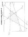
図2に、線分の延長線と基準線との交点を説明する図を示す。図3に、線分と延長線との関係を説明する図を示す。 FIG. 2 shows a diagram for explaining the intersection of the extension line of the line segment and the reference line. FIG. 3 is a diagram illustrating the relationship between the line segment and the extension line.
図2に示した例では、表示装置212の表示領域の境界を示す矩形の2組の辺に相当する直線を基準線B1,B2,B3,B4として用いている。また、図2に示した例では、三角形ABCの辺AB上に、三角形DEFが辺EFを接するように配置されている。これらの三角形ABCおよび三角形DEFが座標変換の対象となる場合に、頂点A,B,C,D,E,Fの座標を含む頂点情報が、図形描画装置100に入力される。なお、以下の説明では、各頂点および辺および線分と基準線との交点の座標は、例えば、表示領域の左下を原点とし、水平走査方向をX軸、垂直走査方向をY軸とする座標系に基づいて表される。 In the example shown in FIG. 2, straight lines corresponding to two sets of sides of the rectangle indicating the boundary of the display area of the display device 212 are used as the reference lines B1, B2, B3, and B4. In the example shown in FIG. 2, the triangle DEF is arranged on the side AB of the triangle ABC so as to contact the side EF. When these triangle ABC and triangle DEF are subject to coordinate transformation, vertex information including the coordinates of vertices A, B, C, D, E, and F is input to the graphic drawing apparatus 100. In the following description, the coordinates of the intersection of each vertex, side, line segment, and reference line are, for example, coordinates with the lower left corner of the display area as the origin, the horizontal scanning direction as the X axis, and the vertical scanning direction as the Y axis. Expressed based on the system.
図1に示した交点座標算出部102は、頂点情報に含まれる各頂点の頂点座標に基づいて、これらの頂点に対応する辺を延長した直線と、上述した基準線B1,B2,B3,B4のうち2つとの交点座標を算出する。同様に、折れ線図形に含まれる各線分や独立した線分についても、それぞれの端点の座標に基づいて、上述した基準線B1,B2,B3,B4のうち2つとの交点座標が算出される。 The intersection coordinate
図2に示した例では、三角形ABCの辺ABの延長線L1と、三角形DEFの辺EFの延長線とは一致しているので、それぞれの辺に対応する基準線との交点として同一の交点座標の組が得られる。In the example shown in FIG. 2, the extension line L1 of the side AB of the triangle ABC, since they match with the extension line of the side EF of the triangle DEF, the same as the intersection of the reference line corresponding to each of the sides A set of intersection coordinates is obtained.
なお、図2に示した例において、三角形ABCの辺BCおよび辺CAに対応する延長線を符号L2,L3を付して示した。また、三角形DEFの辺DEおよび辺FDに対応する延長線を符号L4,L5を付して示した。更に、これらの延長線L1,L2,L3,L4,L5と上述した基準線B1,B2,B3,B4との2つの交点P1,P2を、それぞれ延長線を示す符号を括弧書きで付して示した。In the example shown in FIG. 2, the extension lines corresponding to the side BC and the side CA of the triangle ABC are shown with reference numerals L2 and L3 . Further, the extension lines corresponding to the side DE and the side FD of the triangle DEF are shown with reference numerals L4 and L5 . Furthermore, two intersection points P1 and P2 of these extension lines L1 , L2 , L3 , L4 , and L5 and the
また、図2に示した各辺および線分と各延長線および各延長線と2つの基準線との交点との関係を、図3の表にまとめて示した。図3の例では、各延長線と2つの基準線との交点は、交点1欄と交点2欄とにそれぞれ示されている。 Further, the relationship between each side and line segment shown in FIG. 2, each extension line, and each intersection between the extension line and two reference lines is shown in the table of FIG. In the example of FIG. 3, the intersections between each extension line and two reference lines are shown in the
このようにして算出された各交点座標は、交点座標変換部103に入力される。また、頂点情報で指定された図形に対して任意の角度の回転や並進移動を行う旨の座標変換指示が交点座標変換部103に入力される。 Each intersection coordinate calculated in this way is input to the intersection coordinate
このとき、交点座標変換部103は、交点座標算出部102から受け取った交点座標に対して、例えば、3行3列の行列式を用いた行列演算によるアフィン変換処理により、座標変換後の交点座標を算出する。 At this time, the intersection coordinate
図4に、交点の座標変換と図形の座標変換との関係を説明する図を示す。図4の例は、図2に示した2つの三角形ABCおよび三角形DEFについて、点Qを中心として反時計回りに回転させる旨の座標変換指示に対応する行列演算の結果を示している。なお、図4において、図2に示した各延長線L1〜L5に対応する交点P1,P2に対応する座標変換後の点を、それぞれの延長線を括弧書きで付した符号P’1,P’2で示した。FIG. 4 is a diagram for explaining the relationship between the coordinate transformation of the intersection and the coordinate transformation of the figure. The example of FIG. 4 shows the result of matrix calculation corresponding to the coordinate conversion instruction to rotate counterclockwise about the point Q for the two triangles ABC and DEF shown in FIG. In FIG. 4, the point P after coordinate transformation corresponding to the intersections P1 and P2 corresponding to the extension lines L1 to L5 shown in FIG. shown in'1, P'2.
そして、図4に、それぞれ網掛けを付して示すように、座標変換後の各交点を結ぶ直線に囲まれた領域として、座標変換後の図形を表すことができる。つまり、座標変換後の交点P’1(L1),P’2(L1)を結ぶ直線L’1と、座標変換後の交点P’1(L2),P’2(L2)を結ぶ直線L’2と、座標変換後の交点P’1(L3),P’2(L3)を結ぶ直線L’3とが囲む領域として、座標変換後の三角形ABCを表すことができる。そして、同様に、座標変換後の交点P’1(L4),P’2(L4)を結ぶ直線L’4と、座標変換後の交点P’1(L1),P’2(L1)を結ぶ直線L’1と、座標変換後の交点P’1(L5),P’2(L5)を結ぶ直線L’5とが囲む領域として、座標変換後の三角形DEFを表すことができる。Then, as shown with shading in FIG. 4, the figure after coordinate conversion can be represented as an area surrounded by straight lines connecting the intersections after coordinate conversion. That is, the straight line L ′1 connecting the intersection points P ′1 (L1 ) and P ′2 (L1 ) after the coordinate conversion and the intersection points P ′1 (L2 ) and P ′2 (L2 ) after the coordinate conversion. 'and2, the intersection point P after the coordinate transformation' straight line L connecting the1 (L3), P as an area where the3 surrounds'2 (L3) the straight line L connecting the' may represent a triangle ABC after coordinate transformation it can. Similarly, the straight line L ′4 connecting the intersection points P ′1 (L4 ) and P ′2 (L4 ) after the coordinate conversion and the intersection points P ′1 (L1 ) and P ′2 ( L1) 'and1, the intersection P after the coordinate transformation' straight line L connecting the1(L 5), as an area surrounding and a5 'straight line L connecting the2(L 5)' to P, the triangle DEF after coordinate transformation Can be represented.
図4に示した例では、座標変換後の三角形ABCの辺ABに対応する境界と、座標変換後の三角形DEFの辺EFに対応する境界とは、同一の直線L’1によって示されている。したがって、座標変換後の三角形ABCの辺ABと、座標変換後の三角形DEFの辺EFとは、演算精度にかかわらず、同一直線上に配置されることが保証される。In the example shown in FIG. 4, the boundary corresponding to the side AB of the triangle ABC after coordinate conversion and the boundary corresponding to the side EF of the triangle DEF after coordinate conversion are indicated by the same straight line L′1 . . Therefore, it is guaranteed that the side AB of the triangle ABC after the coordinate conversion and the side EF of the triangle DEF after the coordinate conversion are arranged on the same straight line regardless of the calculation accuracy.
故に、上述したように、各辺の延長線と所定の基準線との交点を座標変換して、この座標変換後の交点を結ぶ直線で囲まれる領域として図形を表すことにより、座標変換の前後で、図形相互の位置関係の変動を防ぐことができる。これにより、座標演算の精度を上げることなく、座標変換後に図形の間に意図しないスリットや重なりが生じることを防止できる。 Therefore, as described above, before and after coordinate conversion, coordinate conversion is performed on the intersection of the extension line of each side and a predetermined reference line, and the figure is represented as an area surrounded by a straight line connecting the intersection after the coordinate conversion. Thus, fluctuations in the positional relationship between figures can be prevented. Thereby, it is possible to prevent an unintended slit or overlap between figures after coordinate conversion without increasing the accuracy of coordinate calculation.
図1に示した直線決定部104では、交点座標変換部103で得られた座標変換後の交点座標を、図形表示判定部205から通知された情報に基づいて組み合わせ、表示対象として指定された図形の座標変換後の辺に対応する直線の方程式を決定する。 In the straight
また、境界決定部105は、直線決定部104で求められた直線の方程式を、図形表示判定部205から通知された情報に基づいて組み合わせ、表示対象として指定された座標変換後の図形に対応する画像データの範囲の境界を決定する。 Further, the
このようにして決定された範囲の内部に含まれる画素について、表示データ生成部202により、各画素の表示のための表示データの生成が行われる。 The display
次に、表示データ生成部202の処理内容とともに、図形描画装置全体の動作を説明する。
図5に、図形描画処理を表す流れ図を示す。図5に示した例では、交点演算処理部110による交点演算処理を破線で囲んで示した。Next, the operation of the entire graphic drawing apparatus will be described together with the processing contents of the display
FIG. 5 is a flowchart showing the graphic drawing process. In the example illustrated in FIG. 5, the intersection calculation processing by the intersection
図形描画装置100に頂点情報と座標変換指示とが入力されると(ステップ301)、まず、交点算出部102により、頂点情報で示される各線分と上述した基準線との交点が求められる(ステップ302)。このとき、交点算出部102は、各線分についてそれぞれを延長した直線の方程式を求め、この直線の方程式と図2に示した4つの基準線B1,B2,B3,B4に対応する直線の方程式とに基づいて、各線分と基準線との交点を求めることができる。 When the vertex information and the coordinate conversion instruction are input to the graphic drawing apparatus 100 (step 301), first, the
次いで、交点座標変換部103は、交点算出部102によって算出された各交点の座標に対して、例えば、座標変換指示に対応する行列演算を行うことにより、座標変換後の交点座標を求める(ステップ303)。 Next, the intersection coordinate
座標変換後の交点座標と図形表示判定部205から通知された情報とに基づいて、直線決定部104により、表示対象として指定された図形の座標変換後の辺に対応する直線の方程式が決定される(ステップ304)。図形表示判定部205から通知される情報には、例えば、表示対象の図形に含まれる各辺を特定する情報が含まれる。直線決定部104は、この情報に基づいて、各辺に関連付けられた座標変換後の交点座標を選択し、選択した交点座標を結ぶ直線の方程式を求めることができる。図4に示した例では、直線決定部104により、直線L’1〜L’5の方程式E1(x,y)〜E5(x,y)がそれぞれ求められる。Based on the intersection coordinates after the coordinate conversion and the information notified from the graphic
そして、これらの直線L’1〜L’5の方程式と図形表示判定部205から通知された情報とに基づいて、境界決定部105により、表示対象の図形それぞれに対応する範囲の境界が決定される(ステップ305)。図4に示した例では、各三角形の頂点は、時計回りに配置されている。この場合に、座標変換後の三角形ABCに対応する範囲は、座標変換後の三角形ABCの辺AB、辺BC,辺CAにそれぞれ対応する直線の方程式E1(x,y)、E2(x,y)、E3(x,y)を用いて、式(1)のように表される。Based on the equations of these straight lines L ′1 to L ′5 and the information notified from the graphic
{E1(x,y)>0}&{E2(x,y)>0}&{E3(x,y)>0}・・・(1)
この式(1)の条件を満たす座標値で示される画素を抽出することにより、各辺の延長と基準線との交点を座標変換して得られる座標変換後の三角形ABC内部に位置する画素をもれなく抽出することができる。{E1 (x, y)> 0} & {E2 (x, y)> 0} & {E3 (x, y)> 0} (1)
By extracting the pixel indicated by the coordinate value that satisfies the condition of the expression (1), the pixel located inside the triangle ABC after coordinate conversion obtained by coordinate conversion of the intersection of the extension of each side and the reference line is obtained. It can be extracted without leakage.
また、座標変換後の三角形DEFに対応する範囲は、辺DE、辺EF,辺FDにそれぞれ対応する座標変換後の直線の方程式E4(x,y)、E1(x,y)、E5(x,y)を用いて、同様に表される。そして、この範囲に含まれる画素を抽出することにより、各辺の延長と基準線との交点を座標変換して得られる座標変換後の三角形DEF内部に位置する画素をもれなく抽出することができる。Further, the range corresponding to the triangle DEF after the coordinate transformation is the linear equations E4 (x, y), E1 (x, y), E after the coordinate transformation corresponding to the side DE, the side EF, and the side FD, respectively.5 (x, y) is used in the same way. Then, by extracting the pixels included in this range, it is possible to extract all the pixels located inside the triangle DEF after the coordinate conversion obtained by performing the coordinate conversion on the intersection of the extension of each side and the reference line.
このようにして求められた表示対象の各図形の内部の画素は、座標変換前に各図形の内部の画素が分布していた範囲相互の位置関係を維持して分布している。そして、図2に示したように、2つの三角形ABCと三角形DEFとの境界が1つの直線で表されている場合には、座標変換後においても、2つの三角形の境界は、元の直線を座標変換した直線となっている。したがって、座標変換後の2つの三角形の間に意図しない隙間や重なりが表れることはない。 The pixels inside each figure to be displayed thus obtained are distributed while maintaining the positional relationship between the ranges in which the pixels inside each figure were distributed before coordinate conversion. As shown in FIG. 2, when the boundary between the two triangles ABC and the triangle DEF is represented by one straight line, the boundary between the two triangles is the original straight line even after coordinate conversion. It is a straight line after coordinate conversion. Therefore, an unintended gap or overlap between the two triangles after coordinate conversion does not appear.
このようにして抽出された各図形の内部に含まれる各画素の表示データは、次のようにして生成される。 Display data of each pixel included in each figure extracted in this way is generated as follows.
まず、頂点座標変換部203により、頂点情報に含まれる各頂点座標についての座標変換が行われる(ステップ306)。つづいて、図形生成部204により、座標変換後の頂点座標が図形と関連付けられる。また、図形表示判定部205により、座標変換によって表示領域の外側に移動した図形などが、表示対象の図形から除外される。そして、図形表示判定部205により、表示対象として残された各図形について、座標変換後の頂点座標と各頂点と図形との関連を示す情報とが生成され、これらの情報がパラメータ情報生成部206に渡される。 First, the vertex coordinate
パラメータ情報生成部206は、図形表示判定部205からの情報とともに、頂点情報に含まれる頂点パラメータを受け取る。そして、これらの情報に基づいて、各図形の内部に位置する各画素の座標(x、y)について、各パラメータの値を求めるためのパラメータ情報を算出する(ステップ307)。例えば、パラメータ情報生成部206は、パラメータの種類ごとに、頂点座標における当該パラメータの値Sに相当するオフセット値Vofと、x、y方向の座標値がそれぞれ1画素分増大した際の当該パラメータ値の増分dsdx、dsdyを算出することができる。このようにして各パラメータについて求められたオフセット値Vofとパラメータ値の増分dsdx、dsdyとを含むパラメータ情報は、表示データ生成部202に渡される。The parameter information generation unit 206 receives the vertex parameters included in the vertex information together with the information from the graphic
図1に示した表示データ生成部202は、パラメータ算出部207と、画素データ算出部208と、画素表示判定部209とを備えている。 The display
パラメータ算出部207は、上述したステップ305で座標変換後の図形の内部に含まれる画素として抽出された各画素の座標に対応する各パラメータ値S(x,y)を、例えば、下の(2)式に基づいて算出する(ステップ308)。 The
S(x,y)=dsdx*x+dsdy*y+Vof ・・・(2)
このようにして求められた各パラメータ値に基づいて、画素データ算出部208は、座標変換後の各図形の内部に含まれる各画素(x、y)の表示色を表す画素データを算出する(ステップ309)。次いで、画素表示判定部209は、座標変換後の各図形の内部に含まれる各画素(x、y)について、ステンシルテストなどの画素ごとに表示/非表示を判定する処理を行う。そして、この判定処理で非表示と判定された画素を除く各画素の画素データが、表示制御部211に渡され、図形描画処理は終了される。S (x, y) = dsdx * x + dsdy * y + Vof (2)
Based on each parameter value thus obtained, the pixel
図1に示したように構成された図形描画装置100によれば、座標変換の前後で変換対象の図形相互に位置ずれが発生することはない。一方、この図形描画装置100に備えられる頂点座標変換部203および交点座標変換部103における演算精度は、従来の図形描画装置100における座標値の演算精度と同等で十分である。つまり、図1に示したように構成された図形描画装置100によれば、座標値の演算精度を上げずに、複数の図形を座標変換した際の図形相互の位置ずれを抑制することができる。 According to the graphics drawing apparatus 100 configured as shown in FIG. 1, there is no positional deviation between graphics to be converted before and after coordinate conversion. On the other hand, the calculation accuracy in the vertex coordinate
なお、図1に示した構成では、図5において破線で囲んで示した交点演算処理部110による処理と、頂点演算処理部201によって行われる処理(ステップ306,307参照)とを並行して実行することができる。このような並行処理を適用することにより、交点演算処理部110を適用した図形描画装置100全体としての描画処理時間を、頂点座標に基づく座標変換のみを用いる場合と同等に抑えることができる。 In the configuration shown in FIG. 1, the process performed by the intersection
また、図2に示したように、表示領域の境界に対応して複数の基準線を設定したことにより、描画対象の図形に含まれる各辺の延長線と基準線との交点を算出する処理を簡易化することができる。なお、複数の基準線は、表示領域内に描画される任意の図形に含まれる線分の延長と、複数の基準線に含まれる2つが交差するように設定することができる。このような基準線の組み合わせとしては、上述した表示領域の境界に対応して設定される基準線の組のほかに、表示領域に外接する三角形を構成する3つの辺に相当する直線の組が考えられる。 In addition, as shown in FIG. 2, by setting a plurality of reference lines corresponding to the boundaries of the display area, a process for calculating the intersection of the extension line of each side included in the drawing target figure and the reference line Can be simplified. Note that the plurality of reference lines can be set so that the extension of a line segment included in an arbitrary figure drawn in the display area and two included in the plurality of reference lines intersect. As such a combination of reference lines, in addition to the reference line set set corresponding to the boundary of the display area described above, a set of straight lines corresponding to three sides constituting a triangle circumscribing the display area is also included. Conceivable.
次に、上述した交点演算処理部110に備えられる直線決定部104および境界決定部105の具体的構成について説明する。
(実施形態2)
図6に、交点演算処理部の別実施形態を示す。なお、図6に示した構成要素のうち、図1に示した構成要素と同等のものについては、同一の符号を付して示し、その説明は省略する。Next, specific configurations of the straight
(Embodiment 2)
FIG. 6 shows another embodiment of the intersection calculation processing unit. 6 that are the same as those shown in FIG. 1 are given the same reference numerals, and descriptions thereof are omitted.
図6に示した直線決定部104は、図形情報管理部111と、図形管理テーブル112と、直線方程式算出部113とを備えている。また、境界決定部105は、条件設定部114と、条件判定部115とを備えている。 6 includes a graphic information management unit 111, a graphic management table 112, and a linear equation calculation unit 113. The
また、図7に、図形管理テーブルの例を示す。更に、図8に、交点演算処理部の動作を表す流れ図を示す。以下の説明では、図6、図7および図8を参照する。 FIG. 7 shows an example of a graphic management table. Further, FIG. 8 is a flowchart showing the operation of the intersection calculation processing unit. In the following description, reference is made to FIG. 6, FIG. 7 and FIG.
図形情報管理部111は、交点座標算出部102による処理対象となった多角形の各辺および線分を示す線分IDと、各線分に対応して算出された基準線との交点座標とを受け取り、これらを図形管理テーブル112に登録する(図8のステップ311)。図形情報管理部111は、例えば、線分IDに対応して、2つの交点座標1,2を図形管理テーブル112に登録することができる。なお、図7に示した例では、図2に示した2つの三角形ABCと三角形DEFの各辺に対応して、それぞれの辺の延長線と基準線との交点座標が格納されている。また、図7の例では、各交点座標は、対応する延長線を示す番号と2つの交点を区別するための番号とを組み合わせた添え字を付して示されている。 The graphic information management unit 111 obtains the line segment ID indicating each side and line segment of the polygon to be processed by the intersection coordinate
次いで、ステップ312において、交点座標変換部103により、各交点についての座標変換が行われると、図形情報管理部111は、算出された座標変換後の交点座標を用いて、図形管理テーブル112の対応する交点座標を置き換える(ステップ313)。 Next, in
そして、頂点演算処理部201から渡される表示図形情報に基づいて、図形情報管理部111は、図形管理テーブル112に登録された交点座標を、対応する線分が含まれている図形ごとに並べ替える(ステップ314)。図7に示した例では、辺AB,BC,CAを示す線分IDに対応して登録された3組の交点座標1,2が、三角形ABCに関連する情報としてまとめられている。同様に、辺DE,EF,FDを示す線分IDに対応して登録された3組の交点座標1,2は、三角形DEFに関連する情報としてまとめられる。 Based on the display graphic information passed from the vertex calculation processing unit 201, the graphic information management unit 111 rearranges the intersection coordinates registered in the graphic management table 112 for each graphic including the corresponding line segment. (Step 314). In the example shown in FIG. 7, three sets of intersection coordinates 1 and 2 registered corresponding to the line segment IDs indicating the sides AB, BC, and CA are collected as information related to the triangle ABC. Similarly, the three sets of intersection coordinates 1 and 2 registered corresponding to the line segment ID indicating the sides DE, EF, and FD are collected as information related to the triangle DEF.
このようにして整理された図形管理テーブル112の情報に基づいて、直線方程式算出部113は、標示対象の図形に含まれる線分に対応して格納された2つの交点座標を結ぶ直線方程式を求める(ステップ315)。直線方程式算出部113は、例えば、辺ABに対応する直線L1と基準線B1との交点座標1(X11,Y11)と、基準線B3との交点座標2(X12,Y12)とを結ぶ直線方程式E1(x,y)は、式(3)のように表される。Based on the information in the graphic management table 112 arranged in this way, the linear equation calculation unit 113 obtains a linear equation that connects the two intersection coordinates stored corresponding to the line segment included in the graphic to be marked. (Step 315). The straight line equation calculation unit 113, for example, intersects coordinates 1 (X11 , Y11 ) between the straight line L1 corresponding to the side AB and the reference line B1 and intersects coordinates 2 (X12 , Y12 ) between the
E1(x,y)=(Y12−Y11)*x−(X12−X11)*y
−{X11*(Y12−Y11)−Y11*(X12−X11)} ・・・(3)
直線方程式算出部113によって求められた直線方程式は、図形情報管理部111により図形管理テーブル112に格納される(ステップ316)。図7に示した例では、三角形ABCの辺AB上に三角形DEFの辺EFが配置されていることが、これらの両辺に対応して同一の直線方程式E1(x,y)が格納されていることによって表されている。そして、この図形管理テーブル112は、条件設定部114による処理に供される。E1 (x, y) = (Y12 −Y11 ) * x− (X12 −X11 ) * y
− {X11 * (Y12 −Y11 ) −Y11 * (X12 −X11 )} (3)
The linear equation obtained by the linear equation calculation unit 113 is stored in the graphic management table 112 by the graphic information management unit 111 (step 316). In the example shown in FIG. 7, the side EF of the triangle DEF is arranged on the side AB of the triangle ABC. The same linear equation E1 (x, y) is stored corresponding to both sides. Is represented by The graphic management table 112 is used for processing by the condition setting unit 114.
条件設定部114は、表示図形情報で示された表示対象の図形に含まれる各辺に対応して、図形管理テーブル112に格納された直線方程式を用いて、図形内部に含まれる範囲を示す条件を設定する(ステップ317)。条件設定部114によって設定される条件は、実施形態1の説明において示した式(1)のように表すことができる。 The condition setting unit 114 uses a linear equation stored in the graphic management table 112 to indicate the range included in the graphic corresponding to each side included in the graphic to be displayed indicated by the display graphic information. Is set (step 317). The condition set by the condition setting unit 114 can be expressed as in Expression (1) shown in the description of the first embodiment.
そして、条件判定部115は、このようにして設定された条件に基づいて、表示対象の図形内部に含まれる画素を抽出し(ステップ318)、処理を終了する。例えば、条件判定部115は、表示領域内の各画素の座標について、順次に、各図形について設定された条件を満たすか否かを判定し、条件を満たす画素を表示データ生成部202に通知することができる。 Then, the condition determination unit 115 extracts pixels included in the graphic to be displayed based on the conditions set in this way (step 318), and ends the process. For example, the condition determination unit 115 sequentially determines whether or not the condition set for each figure is satisfied for the coordinates of each pixel in the display area, and notifies the display
このように、直線決定部104および境界決定部105の機能は、数値演算処理回路、論理演算処理回路および記憶素子を用いて実現することができる。 As described above, the functions of the straight
ところで、個々の図形は、複数の直線で囲まれる範囲として表すこともできる。したがって、上述した頂点情報に代えて、図形を複数の直線で囲まれる範囲として表す図形定義情報に基づいて、図形の描画を行う図形描画装置を構成することも可能である。
(実施形態3)
図9に、図形描画装置の別実施形態を示す。なお、図9に示した構成要素のうち、図1に示した構成要素と同等のものについては、同一の符号を付して示し、その説明は省略する。By the way, each figure can also be expressed as a range surrounded by a plurality of straight lines. Therefore, instead of the vertex information described above, it is possible to configure a graphic drawing apparatus that draws a graphic based on graphic definition information that represents a graphic as a range surrounded by a plurality of straight lines.
(Embodiment 3)
FIG. 9 shows another embodiment of the graphic drawing apparatus. 9 that are the same as those shown in FIG. 1 are given the same reference numerals, and descriptions thereof are omitted.
図9に示した交点座標入力部101は、図1に示した交点座標算出部102とは異なる交点座標算出部116を備えている。この交点座標算出部116は、図形定義情報に基づいて、各図形の定義に用いられている各直線と上述した基準線との交点座標を算出する。 The intersection coordinate input unit 101 shown in FIG. 9 includes an intersection coordinate
また、図9に示した直線決定部104は、交点座標変換部103によって得られた座標変換後の交点座標に基づいて、各図形の定義に用いられている各直線に対応する座標変換後の直線の方程式を求める。 Further, the straight
図9に示した頂点演算処理部201は、頂点座標変換部203、図形生成部204に代えて、頂点座標算出部213および図形生成部214を備えている。頂点座標算出部213は、直線決定部104によって各図形の辺に対応して求められた各直線の方程式相互の交点を算出する。そして、算出した交点の座標を描画対象の各図形の頂点座標として図形生成部214に渡す。図形生成部214は、頂点座標算出部213から受け取った頂点座標および頂点座標の算出に用いられた各直線の方程式を、図形定義情報とに基づいて関連付けて、座標変換後の各図形を特定する情報を生成する。そして、この情報に基づいて、図形表示判定部205およびパラメータ情報生成部206の処理が行われる。 The vertex calculation processing unit 201 illustrated in FIG. 9 includes a vertex coordinate calculation unit 213 and a
図9に示した構成では、図形生成部214によって特定される座標変換後の図形の辺は、直線決定部104によって座標変換後の各交点に基づいて求められた直線の方程式に基づいて特定されている。そして、これらの直線の交点座標が、図形生成部214によって特定される座標変換後の図形の頂点座標となる。 In the configuration shown in FIG. 9, the sides of the figure after coordinate conversion specified by the
したがって、図9に示した構成では、パラメータ情報生成部206によって算出される各パラメータS(x,y)のオフセット値Vofおよび増分dsdx、dsdyにも、交点演算処理部110による演算結果が反映される。 Therefore, in the configuration shown in FIG. 9, the calculation result by the intersection
なお、以上に説明した実施形態1、実施形態2および実施形態3に備えられる各部の機能は、同等の数値演算処理および論理演算処理を行うためのプログラムをコンピュータに実行させることによって実現することができる。 In addition, the function of each part with which
100 図形描画装置
101 交点座標入力部
102.116 交点座標算出部
103 交点座標変換部
104 直線決定部
105 境界決定部
110 交点演算処理部
111 図形情報管理部
112 図形管理テーブル
113 直線方程式算出部
114 条件設定部
115 条件判定部
201 頂点演算処理部
202 表示データ生成部
203 頂点座標変換部
204,214 図形生成部
205 図形表示判定部
206 パラメータ情報生成部
207 パラメータ算出部
208 画素データ算出部
209 画素表示判定部
211 表示制御装置
212 表示装置
213 頂点座標算出部DESCRIPTION OF SYMBOLS 100 Graphic drawing apparatus 101 Intersection coordinate input part 102.116 Intersection coordinate
Claims (5)
Translated fromJapanese前記各線分に対応する交点に対して、前記少なくとも一つの図形への適用が指示された座標変換を適用して、変換後の座標を算出する交点座標変換部と、
前記各線分に対応する座標変換後の交点を結ぶ直線の方程式を求める直線決定部と、
前記各線分に対応して求められた直線の方程式に基づいて、前記少なくとも一つの図形の境界を決定する境界決定部と
を備えたことを特徴とする図形描画装置。For each line segment including each side included in at least one figure to be drawn, an intersection coordinate input unit that inputs coordinates representing the position of the intersection of the straight line obtained by extending each line segment and two of the plurality of reference lines;
An intersection coordinate conversion unit that calculates coordinate after conversion by applying coordinate conversion instructed to apply to the at least one figure to the intersection corresponding to each line segment;
A straight line determination unit for obtaining an equation of a straight line connecting the intersections after coordinate transformation corresponding to each of the line segments;
A graphic drawing apparatus comprising: a boundary determining unit that determines a boundary of the at least one graphic based on a straight line equation obtained corresponding to each line segment.
前記交点座標入力部は、前記少なくとも一つの図形の頂点を含む前記各線分の端点の座標に基づいて、前記各線分を延長した直線と複数の基準線のうち2つとの交点の座標を求める交点座標算出部を備えた
ことを特徴とする図形描画装置。The figure drawing apparatus according to claim 1,
The intersection coordinate input unit obtains the coordinates of the intersection of a straight line obtained by extending each line segment and two of a plurality of reference lines based on the coordinates of the end points of each line segment including the vertex of the at least one figure. A graphic drawing apparatus comprising a coordinate calculation unit.
前記境界決定部は、
前記少なくとも一つの図形が多角形である場合に、前記多角形の各辺に対応して求められた直線の方程式を用いて、前記多角形の内部の点が満たすべき条件を設定する条件設定部と、
前記条件設定部によって設定された条件に基づいて、前記多角形が表示される表示画面に含まれる各画素が前記多角形の内側であるか否かを判定する条件判定部とを備えた
ことを特徴とする図形描画装置。The figure drawing apparatus according to claim 1,
The boundary determination unit
When the at least one figure is a polygon, a condition setting unit that sets a condition to be satisfied by a point inside the polygon using a straight line equation corresponding to each side of the polygon When,
A condition determining unit that determines whether each pixel included in the display screen on which the polygon is displayed is inside the polygon based on the condition set by the condition setting unit. Characteristic drawing device.
前記各線分に対応する交点に対して、前記少なくとも一つの図形への適用が指示された座標変換を適用して、変換後の座標を算出する交点座標変換手順と、
前記各線分に対応する座標変換後の交点を結ぶ直線の方程式を求める直線決定手順と、
前記各線分に対応して求められた直線の方程式に基づいて、前記少なくとも一つの図形の境界を決定する境界決定手順と
を備えたことを特徴とする図形描画方法。An acceptance procedure for receiving an input of coordinates indicating the position of an intersection of a straight line obtained by extending each line segment and two of a plurality of reference lines for each line segment including each side included in at least one figure to be drawn;
Applying coordinate transformation instructed to apply to the at least one figure to the intersection corresponding to each line segment, an intersection coordinate transformation procedure for calculating coordinates after transformation,
A straight line determination procedure for obtaining an equation of a straight line connecting the intersections after coordinate transformation corresponding to each of the line segments;
A graphic drawing method comprising: a boundary determination procedure for determining a boundary of the at least one graphic based on a straight line equation obtained corresponding to each line segment.
前記境界決定手順は、
前記少なくとも一つの図形が多角形である場合に、前記多角形の各辺に対応して求められた直線の方程式を用いて、前記多角形の内部の点が満たすべき条件を設定する条件設定手順と、
前記条件設定手順によって設定された条件に基づいて、前記多角形が表示される表示画面に含まれる各画素が前記多角形の内側であるか否かを判定する条件判定手順とを備えた
ことを特徴とする図形描画方法。
The figure drawing method according to claim 4,
The boundary determination procedure includes:
A condition setting procedure for setting a condition to be satisfied by a point inside the polygon using an equation of a straight line obtained corresponding to each side of the polygon when the at least one figure is a polygon When,
A condition determination procedure for determining whether or not each pixel included in the display screen on which the polygon is displayed is inside the polygon based on the condition set by the condition setting procedure. Characteristic drawing method.
Priority Applications (1)
| Application Number | Priority Date | Filing Date | Title |
|---|---|---|---|
| JP2010051442AJP5418310B2 (en) | 2010-03-09 | 2010-03-09 | Graphic drawing apparatus and method |
Applications Claiming Priority (1)
| Application Number | Priority Date | Filing Date | Title |
|---|---|---|---|
| JP2010051442AJP5418310B2 (en) | 2010-03-09 | 2010-03-09 | Graphic drawing apparatus and method |
Publications (2)
| Publication Number | Publication Date |
|---|---|
| JP2011186786A JP2011186786A (en) | 2011-09-22 |
| JP5418310B2true JP5418310B2 (en) | 2014-02-19 |
Family
ID=44792973
Family Applications (1)
| Application Number | Title | Priority Date | Filing Date |
|---|---|---|---|
| JP2010051442AExpired - Fee RelatedJP5418310B2 (en) | 2010-03-09 | 2010-03-09 | Graphic drawing apparatus and method |
Country Status (1)
| Country | Link |
|---|---|
| JP (1) | JP5418310B2 (en) |
Families Citing this family (1)
| Publication number | Priority date | Publication date | Assignee | Title |
|---|---|---|---|---|
| CN110163975B (en)* | 2019-05-24 | 2023-04-14 | 武汉轻工大学 | Method, device, equipment and storage medium for drawing a straight line in space |
Family Cites Families (4)
| Publication number | Priority date | Publication date | Assignee | Title |
|---|---|---|---|---|
| JPH05242235A (en)* | 1992-02-27 | 1993-09-21 | Dainippon Screen Mfg Co Ltd | Picture processor |
| JP2001109457A (en)* | 1999-10-13 | 2001-04-20 | Yamaha Corp | Method and device for image processing |
| JP2010039680A (en)* | 2008-08-04 | 2010-02-18 | Fujitsu Ltd | Image processor, image processing program, and image processing method |
| JP2011028641A (en)* | 2009-07-28 | 2011-02-10 | Fujitsu Ltd | Image processing device and image processing method |
- 2010
- 2010-03-09JPJP2010051442Apatent/JP5418310B2/ennot_activeExpired - Fee Related
Also Published As
| Publication number | Publication date |
|---|---|
| JP2011186786A (en) | 2011-09-22 |
Similar Documents
| Publication | Publication Date | Title |
|---|---|---|
| JP6144364B2 (en) | Work support data creation program | |
| JP2011212314A (en) | Blood vessel display control equipment and method, and program | |
| JP5047124B2 (en) | Parts identification image creation apparatus and method, parts identification display apparatus and method, program, and storage medium | |
| US10403040B2 (en) | Vector graphics rendering techniques | |
| JP2018142109A (en) | Display control program, display control method, and display control apparatus | |
| JP2009080573A (en) | Display method | |
| JP2020178221A (en) | Projection control device, projection control method and program | |
| US12283035B2 (en) | Information display apparatus, information display method, and information display program | |
| JP2009009345A (en) | Vector image drawing device, vector image drawing method, and program | |
| JP5418310B2 (en) | Graphic drawing apparatus and method | |
| JP3547250B2 (en) | Drawing method | |
| JP4760550B2 (en) | Image conversion apparatus and image conversion program | |
| JP2020113247A (en) | Image processing apparatus, control method thereof, and information processing system | |
| JP6028703B2 (en) | Graph generation apparatus, graph generation method, and graph generation program | |
| JP2020013390A (en) | Information processing apparatus, information processing program, and information processing method | |
| US11074670B2 (en) | Image processing apparatus, control method thereof, recording medium, and information processing system | |
| JP2001202402A (en) | Drawing creation device and drawing change display method | |
| JP2002211099A (en) | Trapping region generating method, trapping region generating device, trapping region generating program, and trapping region generating program storage medium | |
| JP3872056B2 (en) | Drawing method | |
| JP4490215B2 (en) | Data display device and program | |
| TW201616216A (en) | Pattern correction amount calculation device, pattern correction amount calculation method, and recording medium | |
| JP2021064334A (en) | Image processing apparatus, image processing method, and program | |
| JP2017040488A (en) | Three-dimensional temperature distribution display device | |
| JP5846704B2 (en) | Booklet creation method and program | |
| JP2020080064A (en) | Projection control device, projection device, control method of projection device, program, and storage medium |
Legal Events
| Date | Code | Title | Description |
|---|---|---|---|
| A621 | Written request for application examination | Free format text:JAPANESE INTERMEDIATE CODE: A621 Effective date:20130108 | |
| A977 | Report on retrieval | Free format text:JAPANESE INTERMEDIATE CODE: A971007 Effective date:20131016 | |
| A01 | Written decision to grant a patent or to grant a registration (utility model) | Free format text:JAPANESE INTERMEDIATE CODE: A01 Effective date:20131022 | |
| A61 | First payment of annual fees (during grant procedure) | Free format text:JAPANESE INTERMEDIATE CODE: A61 Effective date:20131104 | |
| LAPS | Cancellation because of no payment of annual fees |