JP5416140B2 - Dynamic adjustment of downlink / uplink allocation ratio in TDD radio system - Google Patents
Dynamic adjustment of downlink / uplink allocation ratio in TDD radio systemDownload PDFInfo
- Publication number
- JP5416140B2 JP5416140B2JP2010546066AJP2010546066AJP5416140B2JP 5416140 B2JP5416140 B2JP 5416140B2JP 2010546066 AJP2010546066 AJP 2010546066AJP 2010546066 AJP2010546066 AJP 2010546066AJP 5416140 B2JP5416140 B2JP 5416140B2
- Authority
- JP
- Japan
- Prior art keywords
- mute
- interval
- downlink
- uplink
- frame structure
- Prior art date
- Legal status (The legal status is an assumption and is not a legal conclusion. Google has not performed a legal analysis and makes no representation as to the accuracy of the status listed.)
- Active
Links
- 238000000034methodMethods0.000claimsdescription105
- 230000005540biological transmissionEffects0.000claimsdescription67
- 238000004891communicationMethods0.000claimsdescription37
- 230000008859changeEffects0.000claimsdescription30
- 238000012545processingMethods0.000claimsdescription15
- 238000011084recoveryMethods0.000claimsdescription10
- 230000000694effectsEffects0.000claimsdescription8
- 238000012790confirmationMethods0.000claimsdescription5
- 230000000977initiatory effectEffects0.000claimsdescription5
- 230000004044responseEffects0.000claimsdescription4
- 230000011664signalingEffects0.000description46
- 230000006870functionEffects0.000description15
- 230000008569processEffects0.000description14
- 238000004590computer programMethods0.000description12
- 238000004422calculation algorithmMethods0.000description7
- 230000007704transitionEffects0.000description6
- 238000005516engineering processMethods0.000description4
- 230000001360synchronised effectEffects0.000description4
- 230000001413cellular effectEffects0.000description3
- 238000013468resource allocationMethods0.000description3
- 238000005259measurementMethods0.000description2
- 230000003287optical effectEffects0.000description2
- 238000013515scriptMethods0.000description2
- 230000006399behaviorEffects0.000description1
- 230000009286beneficial effectEffects0.000description1
- 230000003111delayed effectEffects0.000description1
- 238000007726management methodMethods0.000description1
- 238000012544monitoring processMethods0.000description1
- 238000011017operating methodMethods0.000description1
- 230000002085persistent effectEffects0.000description1
- 230000000644propagated effectEffects0.000description1
- 239000004065semiconductorSubstances0.000description1
- 230000007480spreadingEffects0.000description1
- 239000000758substrateSubstances0.000description1
- 239000002699waste materialSubstances0.000description1
Images


Classifications
- H—ELECTRICITY
- H04—ELECTRIC COMMUNICATION TECHNIQUE
- H04B—TRANSMISSION
- H04B7/00—Radio transmission systems, i.e. using radiation field
- H04B7/24—Radio transmission systems, i.e. using radiation field for communication between two or more posts
- H04B7/26—Radio transmission systems, i.e. using radiation field for communication between two or more posts at least one of which is mobile
- H04B7/2643—Radio transmission systems, i.e. using radiation field for communication between two or more posts at least one of which is mobile using time-division multiple access [TDMA]
- H04B7/2656—Radio transmission systems, i.e. using radiation field for communication between two or more posts at least one of which is mobile using time-division multiple access [TDMA] for structure of frame, burst
- H—ELECTRICITY
- H04—ELECTRIC COMMUNICATION TECHNIQUE
- H04L—TRANSMISSION OF DIGITAL INFORMATION, e.g. TELEGRAPHIC COMMUNICATION
- H04L5/00—Arrangements affording multiple use of the transmission path
- H04L5/14—Two-way operation using the same type of signal, i.e. duplex
- H—ELECTRICITY
- H04—ELECTRIC COMMUNICATION TECHNIQUE
- H04L—TRANSMISSION OF DIGITAL INFORMATION, e.g. TELEGRAPHIC COMMUNICATION
- H04L5/00—Arrangements affording multiple use of the transmission path
- H04L5/14—Two-way operation using the same type of signal, i.e. duplex
- H04L5/1469—Two-way operation using the same type of signal, i.e. duplex using time-sharing
- H—ELECTRICITY
- H04—ELECTRIC COMMUNICATION TECHNIQUE
- H04W—WIRELESS COMMUNICATION NETWORKS
- H04W56/00—Synchronisation arrangements
- H04W56/003—Arrangements to increase tolerance to errors in transmission or reception timing
- H—ELECTRICITY
- H04—ELECTRIC COMMUNICATION TECHNIQUE
- H04W—WIRELESS COMMUNICATION NETWORKS
- H04W72/00—Local resource management
- H04W72/12—Wireless traffic scheduling
- H04W72/1263—Mapping of traffic onto schedule, e.g. scheduled allocation or multiplexing of flows
- H—ELECTRICITY
- H04—ELECTRIC COMMUNICATION TECHNIQUE
- H04W—WIRELESS COMMUNICATION NETWORKS
- H04W72/00—Local resource management
- H04W72/20—Control channels or signalling for resource management
- H04W72/23—Control channels or signalling for resource management in the downlink direction of a wireless link, i.e. towards a terminal
- H—ELECTRICITY
- H04—ELECTRIC COMMUNICATION TECHNIQUE
- H04W—WIRELESS COMMUNICATION NETWORKS
- H04W72/00—Local resource management
- H04W72/50—Allocation or scheduling criteria for wireless resources
- H04W72/53—Allocation or scheduling criteria for wireless resources based on regulatory allocation policies
- H—ELECTRICITY
- H04—ELECTRIC COMMUNICATION TECHNIQUE
- H04W—WIRELESS COMMUNICATION NETWORKS
- H04W72/00—Local resource management
- H04W72/50—Allocation or scheduling criteria for wireless resources
- H04W72/535—Allocation or scheduling criteria for wireless resources based on resource usage policies
- H—ELECTRICITY
- H04—ELECTRIC COMMUNICATION TECHNIQUE
- H04W—WIRELESS COMMUNICATION NETWORKS
- H04W72/00—Local resource management
- H04W72/04—Wireless resource allocation
- H04W72/044—Wireless resource allocation based on the type of the allocated resource
- H04W72/0446—Resources in time domain, e.g. slots or frames
Landscapes
- Engineering & Computer Science (AREA)
- Signal Processing (AREA)
- Computer Networks & Wireless Communication (AREA)
- Mobile Radio Communication Systems (AREA)
- Bidirectional Digital Transmission (AREA)
Description
Translated fromJapanese関連出願への相互参照
本出願は、2008年2月8日に出願された米国仮出願番号第61/027,412号、発明の名称「Dynamic Adjustment of Downlink/Uplink Allocation Ratio in TDD Wireless Systems」の優先権を主張し、この文献の全体の内容は、参照によって本願に援用される。Cross-reference to related applications This application is based on US Provisional Application No. 61 / 027,412 filed February 8, 2008, entitled “Dynamic Adjustment of Downlink / Uplink Allocation Ratio in TDD Wireless Systems”. Priority is claimed and the entire contents of this document are hereby incorporated by reference.
本発明は、無線通信に関する。 The present invention relates to wireless communication.
無線通信システム、例えば、無線時分割複信(Time Division Duplex:TDD)システムは、例えば、ユーザ設備(user equipment:UE)、移動局(mobile station:MS)、携帯電話機又は無線エアカード等の移動機器と通信する1つ以上の基地局のネットワークを含むことができる。更に、無線通信システムは、基地局を制御するためのコアネットワークを含むことができる。 A radio communication system, for example, a radio time division duplex (TDD) system, for example, a user equipment (UE), a mobile station (mobile station: MS), a mobile phone or a radio air card or the like It may include a network of one or more base stations that communicate with the device. Further, the wireless communication system can include a core network for controlling the base station.
無線TDDシステムは、分離された重なり合わないタイムインターバルで、同じ搬送波周波数を介するダウンリンク送信及びアップリンク送信をサポートできる。基地局は、1つ以上の移動機器に、ダウンリンク信号と呼ばれる信号を送信することができる。移動機器は、1つ以上の基地局に、アップリンク信号と呼ばれる信号を送信することができる。無線システムは、フレーム内でダウンリンク送信及びアップリンク送信を制御するために、ダウンリンクインターバル及びアップリンクインターバルを割り当てることができる。 A wireless TDD system can support downlink and uplink transmissions over the same carrier frequency with separate non-overlapping time intervals. A base station can transmit a signal called a downlink signal to one or more mobile devices. A mobile device can transmit a signal called an uplink signal to one or more base stations. The wireless system can assign downlink and uplink intervals to control downlink and uplink transmissions within the frame.
本出願は、特に、無線通信のためのダウンリンク及びアップリンクの割当を動的に変更する技術を開示する。 In particular, the present application discloses techniques for dynamically changing downlink and uplink assignments for wireless communications.
ダウンリンク及びアップリンク割当を動的に変更する技術は、基地局とユーザ設備との間で通信リンク(通信リンクは、基地局がユーザ設備に送信を行うダウンリンクインターバルと、ユーザ設備が基地局に送信を行うアップリンクインターバルとを含むことができる。)を確立するステップと、ミュートインターバルを生成し、前フレームにおけるダウンリンクインターバル又はアップリンクインターバルを置換して、次フレームのダウンリンク−アップリンク割当比を変更するステップと、フレーム構造を用いて、ミュートインターバルの位置をユーザ設備に送信するステップとを有していてもよい。他の実施例は、対応するシステム、装置及びコンピュータプログラム製品を含むことができる。 The technology for dynamically changing the downlink and uplink allocation is a communication link between the base station and the user equipment (the communication link is a downlink interval in which the base station transmits to the user equipment, and the user equipment And an uplink interval for transmitting to the next frame), and generating a mute interval to replace the downlink interval or uplink interval in the previous frame, and the downlink-uplink in the next frame You may have the step which changes an allocation ratio, and the step which transmits the position of a mute interval to user equipment using a frame structure. Other embodiments may include corresponding systems, devices, and computer program products.
ダウンリンク及びアップリンク割当を動的に変更する技術は、基地局を時分割複信で動作させ、フレーム構造を用いて、1つ以上の移動機器と通信させるステップと、ダウンリンク−アップリンク比を調整して、フレーム構造内のアップリンクデータ容量とダウンリンクデータ容量との間で割当を変更するステップと、調整されたダウンリンク−アップリンク比に基づいて、ミュートインターバルを決定するステップと、ミュートインターバルに基づいて、割当の変更によって影響があるフレーム構造の1つ以上の領域を特定するミュート情報を生成するステップと、ミュート情報を1つ以上の移動機器に送信するステップとを有していてもよい。他の実施例は、対応するシステム、装置及びコンピュータプログラム製品を含むことができる。 A technique for dynamically changing downlink and uplink assignments comprises operating a base station in time division duplex and communicating with one or more mobile devices using a frame structure, and a downlink-uplink ratio. Adjusting the allocation between uplink data capacity and downlink data capacity in the frame structure; determining a mute interval based on the adjusted downlink-uplink ratio; Based on the mute interval, the method includes a step of generating mute information for identifying one or more regions of the frame structure affected by the change of assignment, and a step of transmitting the mute information to one or more mobile devices. May be. Other embodiments may include corresponding systems, devices, and computer program products.
技術は、時分割複信を用いて、フレーム構造と、第1の割当とを使用して基地局と通信するステップと、基地局から、フレーム構造の特定の領域のミュートアクティビティを示し、及び第1の割当とは異なる第2の割当を示すミュート情報を受信するステップと、第1の割当に基づいて、特定の領域に関連する動作を完了するステップと、第2の割当を用いる動作を開始するステップとを有していてもよい。フレーム構造は、アップリンクデータ領域と、ダウンリンクデータ領域とを含むことができる。第1の割当は、アップリンク領域の総サイズと、ダウンリンク領域の総サイズとを含むことができる。他の実施例は、対応するシステム、装置及びコンピュータプログラム製品を含むことができる。 The technique shows using a time division duplex to communicate with a base station using a frame structure and a first assignment, from the base station, showing mute activity for a particular region of the frame structure, and Receiving mute information indicating a second assignment different from the one assignment, completing an operation related to a specific area based on the first assignment, and starting an operation using the second assignment There may be a step of performing. The frame structure may include an uplink data area and a downlink data area. The first allocation may include a total size of the uplink region and a total size of the downlink region. Other embodiments may include corresponding systems, devices, and computer program products.
装置は、フレーム構造を用いて、1つ以上の移動機器と時分割複信で通信する送受信機と、送受信機と通信し、ダウンリンク−アップリンク比を調整して、フレーム構造内のアップリンクデータ容量とダウンリンクデータ容量との間で割当を変更するステップと、調整されたダウンリンク−アップリンク比に基づいて、フレーム構造の1つ以上の領域を含むことができるミュートインターバルを決定するステップと、ミュートインターバルに基づいて、割当の変更によって影響があるフレーム構造の1つ以上の領域を特定するミュート情報を生成するステップと、ミュート情報を1つ以上の移動機器に送信するステップとを含む動作を実行するように構成された処理ユニットとを備えていてもよい。 An apparatus uses a frame structure to communicate with one or more mobile devices in time division duplex, and to communicate with the transceiver, adjust the downlink-uplink ratio, and uplink in the frame structure Changing the allocation between data capacity and downlink data capacity, and determining a mute interval that may include one or more regions of the frame structure based on the adjusted downlink-uplink ratio. And generating mute information identifying one or more regions of the frame structure affected by the change of assignment based on the mute interval, and transmitting the mute information to the one or more mobile devices. And a processing unit configured to perform the operation.
装置は、基地局と通信する送受信機と、送受信機と通信し、時分割複信を用いて、フレーム構造と、第1の割当とを使用して基地局と通信するステップと、基地局から、フレーム構造の特定の領域のミュートアクティビティを示し、及び第1の割当とは異なる第2の割当を示すミュート情報を受信するステップと、第1の割当に基づいて、特定の領域に関連する動作を完了するステップと、第2の割当を用いる動作を開始するステップとを含む動作を実行するように構成された処理ユニットとを備えていてもよい。フレーム構造は、アップリンクデータ領域と、ダウンリンクデータ領域とを含むことができる。第1の割当は、アップリンク領域の総サイズと、ダウンリンク領域の総サイズとを含むことができる。 The apparatus communicates with the base station, communicates with the transceiver, uses time division duplex, communicates with the base station using the frame structure and the first assignment, and from the base station Receiving mute information indicating a mute activity of a particular region of the frame structure and indicating a second assignment different from the first assignment, and operations associated with the particular region based on the first assignment And a processing unit configured to perform an operation including the step of completing the step and initiating an operation using the second assignment. The frame structure may include an uplink data area and a downlink data area. The first allocation may include a total size of the uplink region and a total size of the downlink region.
無線通信のためのシステムは、コントローラと、1つ以上の基地局とを含むことができる。コントローラは、ダウンリンク−アップリンク比を調整して、フレーム構造内のアップリンクデータ容量とダウンリンクデータ容量との間で割当を変更するステップと、調整されたダウンリンク−アップリンク比に基づいて、フレーム構造の1つ以上の領域を含むことができるミュートインターバルを決定するステップと、ミュートインターバルに基づいて、割当の変更によって影響があるフレーム構造の1つ以上の領域を特定するミュート情報を生成するステップとを含む動作を実行できる。基地局は、コントローラと通信し、フレーム構造を用いて、1つ以上の移動機器と時分割複信で通信し、1つ以上の移動機器にミュート情報を含むデータを送信できる。 A system for wireless communication may include a controller and one or more base stations. The controller adjusts the downlink-uplink ratio to change the allocation between the uplink data capacity and the downlink data capacity in the frame structure, and based on the adjusted downlink-uplink ratio. Determining a mute interval that can include one or more regions of the frame structure, and generating mute information identifying one or more regions of the frame structure that are affected by the change of assignment based on the mute interval The operation including the step of performing can be executed. The base station can communicate with the controller, communicate with one or more mobile devices in time division duplex using the frame structure, and transmit data including mute information to the one or more mobile devices.
本出願に開示されている発明の主題の特定の実施例を実施することによって、以下の潜在的利点の1つ以上が実現される。ダウンリンク−アップリンク(D/U)リソース割当比を動的に変更することによって、帯域効率を向上させることができる。更に、これらの利点は、D/U比を変更する際の基地局間の同期された動作を回避できる点、例えば、D/U比を変更する際の同期されたシャットダウンを回避できる点、及び複数の基地局を有する無線通信システム内で、一時的又は持続的に2つ以上の異なるD/U比が存在することを可能にできる点を含むことができる。更に、これらの利点は、D/U比の変更の間、システム容量損失を最小化又は排除できること、ネットワークの観点から割込みフレームを排除できること、及び/又はユーザトラヒックに割込みがかからないことを含むことができる。 By implementing specific embodiments of the inventive subject matter disclosed in this application, one or more of the following potential advantages will be realized. Bandwidth efficiency can be improved by dynamically changing the downlink-uplink (D / U) resource allocation ratio. Furthermore, these advantages are that synchronized operations between base stations when changing the D / U ratio can be avoided, eg, synchronized shutdown when changing the D / U ratio, and In a wireless communication system having multiple base stations, it can include that it can allow two or more different D / U ratios to exist temporarily or persistently. Further, these advantages may include minimizing or eliminating system capacity loss during D / U ratio changes, eliminating interrupt frames from a network perspective, and / or not interrupting user traffic. it can.
複数の実施例の詳細は、添付の図面及び以下の詳細な説明に開示する。 The details of several embodiments are disclosed in the accompanying drawings and the detailed description below.
各図面における同様の参照符号は、同様の要素を示している。 Like reference symbols in the various drawings indicate like elements.
無線TDDシステムは、TDDフレームベースの通信において、フレーム構造を用いて、ダウンリンク送信及びアップリンク送信を制御することができる。フレーム構造は、ダウンリンク送信、アップリンク送信及びガード期間のためのフレーム内の位置又はインターバルを指定できる。TDD通信では、ダウンリンク送信とアップリンク送信を切り替える場合、ガード期間(guard period:GP)を用いることができる。幾つかの実施例では、基地局及び移動機器は、GPにおいては送信を行わない。例えば、セルラシステム等の幾つかの無線システムの特性のため、ダウンリンク信号からアップリンク信号への切替には、比較的長いGPが必要であり、アップリンク信号からダウンリンク信号への切替は、比較的短いGPで行うことができる。無線TDDシステムは、TDD技術を、多元接続技術、例えば、符号分割多元接続(Code Division Multiple Access:CDMA)又は直交周波数分割多重(Orthogonal Frequency-Division Multiplexing:OFDM)等に結合できる。 The wireless TDD system can control downlink transmission and uplink transmission using a frame structure in TDD frame-based communication. The frame structure can specify a position or interval within the frame for downlink transmission, uplink transmission and guard period. In TDD communication, when switching between downlink transmission and uplink transmission, a guard period (GP) can be used. In some embodiments, base stations and mobile devices do not transmit in GP. For example, due to the characteristics of some wireless systems such as cellular systems, switching from a downlink signal to an uplink signal requires a relatively long GP, and switching from an uplink signal to a downlink signal is This can be done with a relatively short GP. A wireless TDD system can combine TDD technology with multiple access technologies, such as Code Division Multiple Access (CDMA) or Orthogonal Frequency-Division Multiplexing (OFDM).
TDDシステムの利点には、周波数帯域が対になっておらず、帯域幅割当が柔軟である点及びダウンリンク−アップリンクリソース割当比(downlink-to-uplink resource allocation ratio:D/U比)を柔軟に選択できる点が含まれる。トラヒックサービスタイプが異なれば、及びトラヒックフローが変化すれば、D/U比も変化することがある。 Advantages of the TDD system include the fact that frequency bands are not paired, bandwidth allocation is flexible, and downlink-to-uplink resource allocation ratio (D / U ratio). Includes points that can be flexibly selected. The D / U ratio may also change if the traffic service type is different and if the traffic flow changes.
但し、一様で固定のD/U比を必要とするTDDシステムでは、異なるトラヒックサービスタイプ、トラヒックフローの変化、又は異なるサービス領域における異なるダウンリンク/アップリンク用途に適応化できないことがある。一例として、TDDシステムの幾つかの実施例では、例えば、基地局がダウンリンクの送信を行い、移動機器が送信を行わずに信号を受信する際、及び移動機器がアップリンクの送信を行い、基地局が基地局の送信機をオフにして信号を受信する際、システム全体でD/U比を同期させる必要がある。更に、幾つかのTDDの実施例では、基地局と移動機器は、システム内でダウンリンク信号とアップリンク信号とが重複することを回避するために、システム全体のタイミングスケジュールに基づいて送信及び受信を行うことができる。 However, TDD systems that require a uniform and fixed D / U ratio may not be adaptable to different traffic service types, changes in traffic flows, or different downlink / uplink applications in different service areas. As an example, in some embodiments of a TDD system, for example, when a base station transmits a downlink, a mobile device receives a signal without transmitting, and a mobile device transmits an uplink, When the base station receives the signal with the base station transmitter turned off, it is necessary to synchronize the D / U ratio in the entire system. Further, in some TDD embodiments, the base station and mobile equipment transmit and receive based on a system-wide timing schedule to avoid duplication of downlink and uplink signals in the system. It can be performed.
幾つかのTDDシステムの実施例では、システムの基地局と移動機器との間に亘ってD/U比同期を行うことによって、このようなシステムでは、システム全体でD/U比が搬送波周波数毎に1つしかないために不都合が生じることがある。更に、このようなシステムについて、一旦、D/U比が決定されると、D/U比を他の値に変更することは、困難で時間がかかることがある。例えば、同期された形式でD/U比を変更する前に、各送信機は、まず、送信を一斉にオフにする必要があり、又は未完了のトラヒックの連続性を維持するために、自らの送信ボリュームを徐々に低減してゼロにし、次に、他の送信機が完全に停止するまで、場合によっては長時間待機する必要がある。この結果、このようなシステムは、多量のシステム容量を浪費する可能性がある。トラヒックボリュームの損失に加えて、このようなシステムにおける未完了のトラヒックの監視及び管理は、高価で及び/又は時間がかかる処理となることがある。 In some TDD system embodiments, D / U ratio synchronization is performed between the base station of the system and the mobile equipment, so that in such a system, the D / U ratio for each carrier frequency is increased throughout the system. Inconvenience may occur because there is only one. Further, for such systems, once the D / U ratio is determined, changing the D / U ratio to another value can be difficult and time consuming. For example, before changing the D / U ratio in a synchronized fashion, each transmitter must first turn off transmissions all at once, or it can self-maintain in order to maintain continuity of incomplete traffic. It is necessary to gradually reduce the transmission volume to zero and then wait for a long time until the other transmitters are completely stopped. As a result, such systems can waste large amounts of system capacity. In addition to traffic volume loss, monitoring and managing unfinished traffic in such systems can be an expensive and / or time consuming process.
本明細書は、ダウンリンク無線信号及びアップリンク無線信号が同じ搬送波周波数を介するが、異なる期間に送信される、TDDシステムにおける信号の送信及び受信の実施例及び具体例を開示する。TDDシステムは、無線環境内で実現することができる。本発明に基づく無線通信装置、技術及びシステムの具体例及び実施例は、時間領域内におけるダウンリンク−アップリンクリソース割当比を動的に変更することができる。これらの装置、技術及びシステムは、ダウンリンク/アップリンク(D/U)比を変更する際の同期されたシャットダウンを回避することができ、及び一時的又は持続的に、システム内に2つ以上の異なるD/U比を実現することができる。 This specification discloses embodiments and examples of transmission and reception of signals in a TDD system, where downlink radio signals and uplink radio signals are transmitted over the same carrier frequency but at different periods. A TDD system can be implemented in a wireless environment. Embodiments and embodiments of wireless communication devices, techniques and systems according to the present invention can dynamically change the downlink-uplink resource allocation ratio in the time domain. These devices, techniques and systems can avoid synchronized shutdowns when changing the downlink / uplink (D / U) ratio, and more than one in the system, either temporarily or persistently Different D / U ratios can be realized.
更に、これらの装置、技術及びシステムは、様々なシナリオで用いることができる。これらのシナリオは、ネットワークが、古いD/U割当比から新たなD/U割当比に切り替わる必要がある場合、及びネットワークが、1つのサービス領域のD/U割当比を隣接するサービス領域のD/U割当比とは異なるD/U割当比に維持する必要がある場合を含むことができる。 Furthermore, these devices, techniques and systems can be used in various scenarios. These scenarios are the case when the network needs to switch from the old D / U allocation ratio to the new D / U allocation ratio, and when the network changes the D / U allocation ratio of one service area to the D of the adjacent service area. The case where it is necessary to maintain the D / U allocation ratio different from the / U allocation ratio can be included.
異なる無線TDDシステムは、TDDフレームベースの通信において、ダウンリンク送信及びアップリンク送信を制御するために、異なるタイプのフレーム構造を用いることができる。フレーム構造のタイプの具体例は、スロットベースのフレーム構造、例えば、スロット−TDDフレーム、及びシンボルベースのフレーム構造、例えば、シンボル−TDDフレームを含む。 Different wireless TDD systems can use different types of frame structures to control downlink and uplink transmissions in TDD frame-based communications. Specific examples of frame structure types include slot-based frame structures, such as slot-TDD frames, and symbol-based frame structures, such as symbol-TDD frames.
図1は、スロットベースのフレーム構造の具体例を示している。スロットベースのフレーム構造、例えば、スロット−TDDフレームは、ダウンリンクスロット、アップリンクスロット及びガードスロットのうちの1つ以上を含むことができる。幾つかの実施例では、スロットベースのフレーム構造の実施例は、固定長無線フレームを指定でき、複数のスロットを含むことができる。各スロットは、潜在的に、ダウンリンク送信、アップリンク送信、又はダウンリンクスロットに続き及びアップリンクスロットに先立つガード期間のために使用することができる。ダウンリンクスロット又はアップリンクスロットは、1つ以上のデータシンボルを含むことができ、時間的に同じスロット長を有することができる。複数の移動機器がダウンリンクスロット又はアップリンクスロット内で無線リソースを共有できる。例えば、コアネットワーク又は基地局上に位置するスケジューラ等のコンポーネントは、無線リソースのスケジューリングを含む多元接続スキームを制御できる。3GPP及び3GPP2システム等の無線システム、例えば、TD−SCDMA、LTE−TDD、UMB−TDDは、スロットベースのフレーム構造を用いることができる。 FIG. 1 shows a specific example of a slot-based frame structure. A slot-based frame structure, eg, a slot-TDD frame, may include one or more of a downlink slot, an uplink slot, and a guard slot. In some embodiments, an embodiment of a slot-based frame structure can specify a fixed length radio frame and can include multiple slots. Each slot can potentially be used for a downlink transmission, an uplink transmission, or a guard period that follows the downlink slot and precedes the uplink slot. A downlink slot or uplink slot can include one or more data symbols and can have the same slot length in time. Multiple mobile devices can share radio resources in a downlink slot or uplink slot. For example, a component such as a scheduler located on a core network or a base station can control a multiple access scheme that includes scheduling of radio resources. Wireless systems such as 3GPP and 3GPP2 systems, eg TD-SCDMA, LTE-TDD, UMB-TDD, can use a slot-based frame structure.
図2は、ガードスロット構造の具体例を示している。ガード期間のために使用されるスロットは、ガードスロットと呼ばれる。ガードスロットは、アップリンクスロット又はダウンリンクスロットとは異なるインターバルを有することができる。幾つかの実施例では、フレーム内におけるガードスロットの位置は、固定されている。ガードスロットは、ガード期間と、1つ以上のオプションのデータ部分とを含むことができる。幾つかの実施例では、ガード期間に先立つデータ部分は、ダウンリンク信号のためのデータ部分であり、ガード期間に続くデータ部分は、アップリンク信号のためのデータ部分である。ガード期間は、アップリンクからダウンリンクに切り替わる場合、比較的短くすることができる。幾つかの実施例では、ダウンリンクスロットの前にあるアップリンクスロット内の最後の幾つかのデータシンボルを取り除くことによってガード期間を作成できる。 FIG. 2 shows a specific example of the guard slot structure. Slots used for the guard period are called guard slots. A guard slot may have a different interval than an uplink slot or a downlink slot. In some embodiments, the position of the guard slot within the frame is fixed. A guard slot may include a guard period and one or more optional data portions. In some embodiments, the data portion preceding the guard period is the data portion for the downlink signal, and the data portion following the guard period is the data portion for the uplink signal. The guard period can be relatively short when switching from uplink to downlink. In some embodiments, a guard period can be created by removing the last few data symbols in the uplink slot that precede the downlink slot.
フレーム構造内のアップリンクスロットの数に対するダウンリンクスロットの数は、D/U比に関連する。基地局は、1つ以上のダウンリンクスロットを用いて、又は通信チャネル、例えば、ブロードキャストチャネルを用いて、ダウンリンク及びアップリンクスロット割当を通信することができる。無線システムは、D/U割当情報をブロードキャストするために、フレーム内のダウンリンク無線リソースを予約できる。 The number of downlink slots relative to the number of uplink slots in the frame structure is related to the D / U ratio. A base station may communicate downlink and uplink slot assignments using one or more downlink slots or using a communication channel, eg, a broadcast channel. The wireless system can reserve downlink radio resources in a frame to broadcast D / U allocation information.
図3は、シンボルベースのフレーム構造の具体例を示している。シンボルベースのフレーム構造、例えば、シンボル−TDDフレーム構造は、ダウンリンクシンボル、アップリンクシンボル及びガード期間のうちの1つ以上を含むことができる。幾つかの実施例では、シンボルベースのフレーム構造の実施例は、固定長の無線フレームを指定でき、及びダウンリンクシンボルの送信のための期間、ガード期間、及びアップリンクシンボルの送信のための期間を指定することができる。複数の移動機器がダウンリンクシンボル又はアップリンクシンボル上で無線リソースを共有できる。例えば、コアネットワーク又は基地局上に位置するスケジューラ等のコンポーネントは、無線リソースのスケジューリングを含む多元接続スキームを制御できる。ガード期間は、固定の持続時間を有することができる。フレーム内のガード期間の位置は、ガード期間に先行するダウンリンクシンボルの数に依存することができる。 FIG. 3 shows a specific example of a symbol-based frame structure. A symbol-based frame structure, eg, a symbol-TDD frame structure, may include one or more of a downlink symbol, an uplink symbol, and a guard period. In some embodiments, an embodiment of a symbol-based frame structure can specify a fixed-length radio frame, and a period for transmission of downlink symbols, a guard period, and a period for transmission of uplink symbols Can be specified. Multiple mobile devices can share radio resources on the downlink symbol or uplink symbol. For example, a component such as a scheduler located on a core network or a base station can control a multiple access scheme that includes scheduling of radio resources. The guard period can have a fixed duration. The position of the guard period within the frame may depend on the number of downlink symbols preceding the guard period.
フレーム構造内のアップリンクシンボルの数に対するダウンリンクシンボルの数は、D/U比に関連する。したがって、ガード期間の位置もD/U比に関連する。フレーム内でアップリンクからダウンリンクに切り替わる場合、幾つかの実施例では、フレーム内の最後の幾つかのアップリンクシンボルを取り除くことによってガード期間を作成できる。基地局は、1つ以上のダウンリンクシンボルを用いて、又は通信チャネル、例えば、ブロードキャストチャネルを用いて、フレーム内のダウンリンク/アップリンクシンボルの数又はフレーム内のGP位置を通信することができる。無線システムは、D/U割当情報をブロードキャストするために、フレーム内のダウンリンク無線リソースを予約できる。例えば、IEEE802.16(WiMAX)等の無線システムは、シンボルベースのフレーム構造を用いることができる。 The number of downlink symbols relative to the number of uplink symbols in the frame structure is related to the D / U ratio. Therefore, the position of the guard period is also related to the D / U ratio. When switching from uplink to downlink in a frame, in some embodiments, a guard period can be created by removing the last few uplink symbols in the frame. A base station can communicate the number of downlink / uplink symbols in a frame or the GP position in a frame using one or more downlink symbols or using a communication channel, eg, a broadcast channel. . The wireless system can reserve downlink radio resources in a frame to broadcast D / U allocation information. For example, wireless systems such as IEEE 802.16 (WiMAX) can use a symbol-based frame structure.
無線通信システムは、D/U割当の変更をシグナリングするために1つ以上のミュートインターバル(mute interval)を使用することができる。フレーム構造は、ダウンリンクインターバル、アップリンクインターバル及びガード期間に加えて1つ以上のミュートインターバルを含むことができる。異なるタイプのフレーム構造の実施例、例えば、スロットベースのフレーム構造及びシンボルベースのフレーム構造において、ミュートインターバルを用いることができる。 A wireless communication system may use one or more mute intervals to signal a change in D / U assignment. The frame structure may include one or more mute intervals in addition to the downlink interval, the uplink interval, and the guard period. Mute intervals can be used in embodiments of different types of frame structures, eg, slot-based frame structures and symbol-based frame structures.
スロット−TDDフレーム構造では、ミュートインターバルは、1つ以上のスロットを含むことができる。ミュートインターバルのためのスロットは、ミュートスロットと呼ばれる。スロットベースのフレーム構造に基づくフレームは、1つ以上のミュートスロットを有することができる。幾つかの実施例では、ミュートスロットは、図1に示すようなダウンリンクスロット及びアップリンクスロットと同様である。ダウンリンクスロット又はアップリンクスロットをミュートスロットとして示すことによって、D/U割当の変更をシグナリングできる。幾つかの実施例では、一旦、ダウンリンクスロット又はアップリンクスロットがミュートスロットとしてマークされると、このスロットが別様にマークされるまで、例えば、ダウンリンクスロット又はアップリンクスロットとしてマークされるまで、このスロットを新たなユーザトラヒック送信のために使用することができなくなる。無線局、例えば、基地局又は移動機器は、例えば、ミュートスロットを使用する現在のトラヒック送信を完了することによって、又はミュートスロットを使用する全ての既存の送信を直ちに停止することによって、ミュートスロットに応答することができる。無線システムは、スロットをミュートスロットとしてマークし、そのスロット内の全ての既存の送信が終了することを待機することによって、ダウンリンクスロットからアップリンクスロットに、又はその逆に遷移することができる。 In the slot-TDD frame structure, the mute interval may include one or more slots. A slot for a mute interval is called a mute slot. A frame based on a slot-based frame structure can have one or more mute slots. In some embodiments, the mute slots are similar to the downlink and uplink slots as shown in FIG. By indicating a downlink slot or uplink slot as a mute slot, a change in D / U assignment can be signaled. In some embodiments, once a downlink slot or uplink slot is marked as a mute slot, until this slot is marked differently, eg, marked as a downlink slot or uplink slot. This slot cannot be used for new user traffic transmission. A radio station, e.g., a base station or mobile device, may enter a mute slot, e.g., by completing a current traffic transmission using the mute slot, or by immediately stopping all existing transmissions using the mute slot. Can respond. The wireless system can transition from the downlink slot to the uplink slot or vice versa by marking the slot as a mute slot and waiting for all existing transmissions in that slot to finish.
ミュートスロットは、ガードスロットとは異なっていてもよい。幾つかの実施例では、ミュートスロットの持続時間は、ダウンリンク/アップリンクスロットと等しく、ガードスロットは、このような要求を有していなくてもよい。幾つかの実施例では、ミュートスロットは、スロットの全体に亘って新たな送信信号を有さず、ミュートスロットは、トラヒックボリュームを低減してゼロにし、一方、ガードスロットは、ダウンリンク及び/又はアップリンク送信のためのオプションのデータ部分を有することができる。幾つかの実施例では、ミュートスロットは、フレーム構造内の如何なるダウンリンクスロット又はアップリンクスロットであってもよく、ネットワークは、ダウンリンクスロット及びアップリンクスロットの1つ以上をミュートスロットとして動的に割り当て、シグナリングすることができ、一方、ガードスロットは、フレーム構造内で固定の位置を有することができる。 The mute slot may be different from the guard slot. In some embodiments, the duration of the mute slot is equal to the downlink / uplink slot, and the guard slot may not have such a requirement. In some embodiments, the mute slot does not have a new transmission signal throughout the slot, the mute slot reduces the traffic volume to zero, while the guard slot is the downlink and / or It can have an optional data part for uplink transmission. In some embodiments, the mute slot may be any downlink slot or uplink slot in the frame structure, and the network dynamically uses one or more of the downlink and uplink slots as mute slots. The guard slot can have a fixed position within the frame structure, while it can be assigned and signaled.
シンボル−TDDフレーム構造では、ミュートインターバルは、1つ以上のシンボルを含むことができる。ミュートインターバルのためのシンボルは、ミュートシンボルと呼ばれる。シンボルベースのフレーム構造に基づくフレームは、1つ以上のミュートシンボルを有することができる。幾つかの実施例では、ミュートシンボルは、図3に示すようなダウンリンクシンボル及びアップリンクシンボルと同様である。幾つかの実施例では、一旦、ダウンリンクシンボル又はアップリンクシンボルがミュートシンボルとしてマークされると、このシンボルが別様にマークされるまで、例えば、ダウンリンクシンボル又はアップリンクシンボルとしてマークされるまで、このシンボルを新たなユーザトラヒック送信のために使用することができなくなる。無線局、例えば、基地局又は移動機器は、例えば、ミュートシンボルを使用する現在のトラヒック送信を完了することによって、又はミュートシンボルを使用する全ての既存の送信を直ちに停止することによって、ミュートシンボルに応答することができる。無線システムは、シンボルをミュートシンボルとしてマークし、そのシンボル内の全ての既存の送信が終了することを待機することによって、ダウンリンクシンボルからアップリンクシンボルに、又はその逆に遷移することができる。 In the symbol-TDD frame structure, the mute interval may include one or more symbols. The symbol for the mute interval is called a mute symbol. A frame based on a symbol-based frame structure may have one or more mute symbols. In some embodiments, the mute symbols are similar to the downlink and uplink symbols as shown in FIG. In some embodiments, once a downlink symbol or uplink symbol is marked as a mute symbol, until this symbol is marked differently, eg, marked as a downlink symbol or uplink symbol. This symbol cannot be used for new user traffic transmission. A radio station, e.g., a base station or mobile device, becomes a mute symbol, e.g., by completing a current traffic transmission using the mute symbol or by immediately stopping all existing transmissions using the mute symbol. Can respond. The wireless system can transition from the downlink symbol to the uplink symbol or vice versa by marking the symbol as a mute symbol and waiting for all existing transmissions in that symbol to end.
ミュートシンボルは、ガード期間とは異なっていてもよい。幾つかの実施例では、ミュートシンボルの持続時間は、ダウンリンク/アップリンクシンボルと等しく、ガード期間は、このような要求を有していなくてもよい。幾つかの実施例では、コアネットワークは、フレーム構造内のミュートシンボルの数及び位置を明示的にシグナリングでき、一方、ガードシンボルは、無線フレーム内で特定の位置にあり、この位置は、無線フレーム内のダウンリンクシンボルの数から暗示的に推定することができる。 The mute symbol may be different from the guard period. In some embodiments, the duration of the mute symbol is equal to the downlink / uplink symbol, and the guard period may not have such a requirement. In some embodiments, the core network can explicitly signal the number and position of the mute symbols in the frame structure, while the guard symbol is at a specific position in the radio frame, which is the position of the radio frame. Can be implicitly estimated from the number of downlink symbols.
無線通信システムは、1つ以上のミュートインターバルを明示的にシグナリングでき、例えば、スロット−TDDフレーム内のミュートスロット又はシンボル−TDDフレーム内のミュートシンボルをシグナリングする。セルラシステム等の無線システムは、ミュートインターバルの明示的なシグナリングを必要とすることがある。 The wireless communication system can explicitly signal one or more mute intervals, for example, a mute slot in a slot-TDD frame or a mute symbol in a symbol-TDD frame. Wireless systems such as cellular systems may require explicit signaling of mute intervals.
例えば、基地局は、ダウンリンクチャネルを介して、ダウンリンクユーザトラヒックと共に共通参照信号及び共通制御情報を送信することができる。基地局側のダウンリンクスケジューラは、ダウンリンクユーザトラヒックの送信を制御できる。無線システムは、同期及び追跡のための共通参照信号の送信、並びにユーザ設備において実行されるチャネル品質測定をオフにすることができないことがある。ある実施例では、一旦、システムが特定のダウンリンクインターバル、例えば、スロット又はシンボルを、アップリンクインターバル、例えば、スロット又はシンボルに切り替えることを計画すると、システムは、1つ以上の無線局を制御して、影響があるインターバル内の共通参照信号を含む無線信号の発信を停止させることができる。ユーザ設備は、この変更の明示的なシグナリングがなければ、共通参照信号の欠落に気付かないことがあり、この結果、同期/追跡及びチャネル測定を誤って実行してしまうことがある。 For example, the base station can transmit the common reference signal and the common control information together with the downlink user traffic through the downlink channel. The downlink scheduler on the base station side can control transmission of downlink user traffic. The wireless system may not be able to turn off transmission of common reference signals for synchronization and tracking and channel quality measurements performed at user equipment. In one embodiment, once the system plans to switch a particular downlink interval, eg, slot or symbol, to an uplink interval, eg, slot or symbol, the system controls one or more radio stations. Thus, it is possible to stop the transmission of the radio signal including the common reference signal within the affected interval. Without explicit signaling of this change, user equipment may be unaware of missing common reference signals, which may result in erroneous synchronization / tracking and channel measurements.
例えば、ユーザ設備は、アップリンクチャネル、例えば、セルラシステム内のアップリンクチャネルを介して、データトラヒックを自律的に送信し、又はランダムにアクセスを試みることができる。この結果、基地局又はスケジューラは、アップリンク送信を完全に制御できるというわけではない。したがって、一旦、システムがアップリンクインターバルをダウンリンクインターバルに切り替えようとすると、システムは、影響があるインターバル内でユーザ設備が無線信号の発信を終了することを待つ必要がある。自律的な送信状態のユーザ設備は、変更の明示的なシグナリングがない場合、影響があるインターバル内で信号を送信し続けることがある。更に、基地局は、あるユーザ設備からのアップリンク送信を永続的にスケジューリングすることでき、例えば、影響があるインターバル内において、永続的にスケジューリングされた複数のユーザ設備からの送信が存在することがある。システムが、これらのユーザ設備のそれぞれに個々のスケジューリング情報を送信して、影響があるインターバル内での永続的な送信を停止するためには、多量のダウンリンクリソースが必要になることがある。したがって、ダウンリンクを介して単一のシグナリングメッセージをブロードキャストして、影響があるインターバル内の複数の永続的なアップリンク送信を停止することが有益であることがある。 For example, user equipment may autonomously transmit data traffic or attempt random access via an uplink channel, eg, an uplink channel in a cellular system. As a result, the base station or scheduler may not have full control over uplink transmission. Therefore, once the system attempts to switch from the uplink interval to the downlink interval, the system needs to wait for the user equipment to finish sending radio signals within the affected interval. Autonomous transmission state user equipment may continue to transmit signals within the affected interval in the absence of explicit signaling of changes. In addition, the base station can persistently schedule uplink transmissions from certain user equipment, for example, there may be transmissions from multiple user equipment that are permanently scheduled within the affected interval. is there. A large amount of downlink resources may be required for the system to send individual scheduling information to each of these user equipments and stop permanent transmissions within the affected interval. Thus, it may be beneficial to broadcast a single signaling message over the downlink to stop multiple persistent uplink transmissions within the affected interval.
ダウンリンクチャネル、例えば、ブロードキャストチャネルは、明示的なシグナリングを搬送して、1つ以上の移動機器に無線フレーム内のミュートインターバルの位置を通知することができる。更に、ミュートインターバルをシグナリングする手法は、例えば、スロットフレーム構造及びシンボルフレーム構造のように、フレーム構造が異なる実施例の間では、異なっていることがある。例えば、スロット−TDDフレーム構造の実施例では、スロットマスク法(slot mask method)、スロットリスト法(slot list method)又は定義済み割当テーブルエントリ(allocation table entry:ATE)法を用いることができる。一方、シンボル−TDDフレーム構造の実施例では、例えば、シンボルセット法(symbol set method)又はシンボルリスト法(symbol list method)を用いることができる。 A downlink channel, eg, a broadcast channel, can carry explicit signaling to inform one or more mobile devices of the position of the mute interval in the radio frame. Furthermore, the technique for signaling the mute interval may differ between embodiments with different frame structures, such as, for example, a slot frame structure and a symbol frame structure. For example, in the embodiment of the slot-TDD frame structure, a slot mask method, a slot list method, or a predefined allocation table entry (ATE) method can be used. On the other hand, in the embodiment of the symbol-TDD frame structure, for example, a symbol set method or a symbol list method can be used.
図4は、スロットマスクを用いるミュートスロットのシグナリングの具体例を示している。スロットマスク法は、D/U割当テーブルを示す既存のシグナリングフォーマットと共に、N−ビットマスクをブロードキャストすることを含むことができ、ここで、Nは、フレーム内のダウンリンクスロット及びアップリンクスロットの総数に等しい。マスク内のi番目のビットmiは、フレーム内のi番目のデータスロットに対応する。miが1に設定されると、フレーム内のi番目のスロットは、ミュートスロットとして指定され、この他の場合、i番目のスロットは、添付のD/U割当テーブルに基づいて、ダウンリンク送信又はアップリンク送信の何れかのために使用できる。N−ビットマスクは、それぞれが1つ以上のスロットをミュートスロットとして指示する1つ以上のビットを含むことができる。異なる実施例では、異なるスロットマスク法の実施例を実現することができる。例えば、スロットマスクは、フレーム内の割当テーブルから分離してもよい。他の具体例では、結合されたデータ構造が割当テーブル及びスロットマスクの両方を表すことができる。結合されたデータ構造は、N個のエントリを含むことができ、各エントリは、D/U割当のためのビットと、スロットマスク指示のためのビットとを含むことができる。FIG. 4 shows a specific example of mute slot signaling using a slot mask. The slot mask method may include broadcasting an N-bit mask along with an existing signaling format indicating a D / U allocation table, where N is the total number of downlink and uplink slots in the frame. be equivalent to. I-th bit mi in the mask, corresponds to the i-th data slot in the frame. Ifmi is set to 1, the i th slot in the frame is designated as a mute slot, otherwise the i th slot is downlink transmitted based on the attached D / U allocation table. Or can be used for either uplink transmission. The N-bit mask can include one or more bits, each indicating one or more slots as mute slots. In different embodiments, different slot mask method embodiments may be implemented. For example, the slot mask may be separated from the allocation table in the frame. In other implementations, the combined data structure can represent both the allocation table and the slot mask. The combined data structure can include N entries, and each entry can include a bit for D / U assignment and a bit for slot mask indication.
図5は、スロットリストを用いるミュートスロットのシグナリングの具体例を示している。スロットリスト法は、D/U割当テーブルを示すシグナリング情報と共に、1つ以上のスロットインデクスのリストをブロードキャストすることを含むことができる。幾つかの実施例では、フレーム内のスロットのインデクスがフレームのスロットリスト内にある場合、スロットは、ミュートスロットとしてマークされる。このようなマークが付されていない場合、スロットは、フレームのD/U割当テーブルに基づくダウンリンクスロット又はアップリンクスロットの何れかである。異なる実施例では、異なるスロットリスト法の実施例を実現することができる。例えば、ミュートスロットは、互いに隣接して、アップリンクスロットに後続し、及びダウンリンクスロットに先行することができ、この結果、リストのインデクスをミュートされたスロットの数に置換することができる。幾つかの実施例では、ミュートスロットを他のスロットタイプと交互配置(interleaved)することができる。 FIG. 5 shows a specific example of mute slot signaling using a slot list. The slot list method can include broadcasting a list of one or more slot indexes along with signaling information indicating a D / U allocation table. In some embodiments, a slot is marked as a mute slot if the index of the slot in the frame is in the slot list of the frame. If not marked, the slot is either a downlink slot or an uplink slot based on the D / U allocation table of the frame. In different embodiments, different slot list method embodiments may be implemented. For example, the mute slots can be adjacent to each other, follow the uplink slot, and precede the downlink slot, so that the index of the list can be replaced with the number of muted slots. In some embodiments, mute slots can be interleaved with other slot types.
スロット−TDDフレーム構造のための定義済み割当テーブルエントリ法では、定義済みフォーマットを用いて、ミュートスロットの存在及び位置をシグナリングすることができる。例えば、定義済みフォーマットは、ミュートスロットを含むフレームパターンを指定できる。定義済み割当テーブルエントリ法は、TDD割当テーブルの1つ以上の拡張されたエントリ内にミュートスロットシグナリング情報を含むことができる。 In the predefined allocation table entry method for slot-TDD frame structure, the presence and location of mute slots can be signaled using a predefined format. For example, the predefined format can specify a frame pattern including a mute slot. The predefined allocation table entry method may include mute slot signaling information in one or more extended entries of the TDD allocation table.
図6は、シンボルセットを用いるミュートシンボルのシグナリングの具体例を示している。シンボルセット法は、シンボルセット及びD/U割当情報、例えば、ダウンリンク/アップリンクシンボルの数をブロードキャストすることを含むことができる。シンボルセットは、フレーム内のシンボル位置を指定して、各シンボルをミュートシンボルとしてマークすることができる。例えば、シンボルセットは、シンボルをミュートシンボルとして指定するために、フレーム内のシンボルの1つ以上のインデクスを含むことができる。 FIG. 6 shows a specific example of mute symbol signaling using a symbol set. The symbol set method may include broadcasting the symbol set and D / U assignment information, eg, the number of downlink / uplink symbols. The symbol set can mark each symbol as a mute symbol by specifying a symbol position within the frame. For example, a symbol set can include one or more indexes of symbols in a frame to designate the symbol as a mute symbol.
幾つかの実施例では、ブロードキャストされたシンボルセット内のミュートされたダウンリンクシンボルは、シンボル−TDDフレーム構造のタイミング特性のために、時間領域内に連続するミュートインターバルを形成することがある。更に、このような連続するダウンリンクミュートインターバルは、フレーム内のガード期間に隣接することがある。幾つかの実施例では、ブロードキャストされたシンボルセット内のミュートされたアップリンクシンボルは、時間領域内で連続するミュートインターバルを形成することがある。更に、このような連続するアップリンクミュートインターバルは、フレーム内のガード期間に隣接することがある。幾つかの実施例では、基地局は、ミュートシンボルのインデクスをブロードキャストできる。幾つかの実施例では、基地局は、ミュートされたシンボルの数を、これらのシンボルがダウンリンシンボルであるかアップリンクシンボルであるかを示すためのフラグと共に、ブロードキャストできる。幾つかの実施例では、基地局は、ミュートインターバルの開始シンボルインデクス(starting symbol index)を、このミュートインターバルがダウンリンク上であるかアップリンク上であるかを示すフラグと共に、ブロードキャストできる。 In some embodiments, muted downlink symbols in a broadcast symbol set may form consecutive mute intervals in the time domain due to the timing characteristics of the symbol-TDD frame structure. Furthermore, such successive downlink mute intervals may be adjacent to the guard period within the frame. In some embodiments, muted uplink symbols in a broadcast symbol set may form a continuous mute interval in the time domain. Further, such consecutive uplink mute intervals may be adjacent to the guard period within the frame. In some embodiments, the base station can broadcast an index of mute symbols. In some embodiments, the base station can broadcast the number of muted symbols, along with a flag to indicate whether these symbols are downlink symbols or uplink symbols. In some embodiments, the base station can broadcast the starting symbol index of the mute interval with a flag indicating whether the mute interval is on the downlink or uplink.
シンボル−TDDフレーム構造のための定義済み割当テーブルエントリ法では、定義済みフォーマットを用いて、ミュートシンボルの存在及び位置をシグナリングすることができる。例えば、定義済みフォーマットは、ミュートシンボルを含むフレームパターンを指定できる。定義済み割当テーブルエントリ法は、TDD割当テーブルの1つ以上の拡張されたエントリ内にミュートシンボルシグナリング情報を含むことができる。 In the predefined allocation table entry method for the symbol-TDD frame structure, the presence and location of mute symbols can be signaled using a predefined format. For example, the predefined format can specify a frame pattern that includes a mute symbol. The predefined assignment table entry method may include mute symbol signaling information in one or more extended entries of the TDD assignment table.
無線通信の間、フレームは、ミュートインターバルを含んでいても含んでいなくてもよい。ゼロミュートインターバルシグナリング(zero mute interval signaling)は、ミュートインターバルなしのフレームを示す。非ゼロミュートインターバルシグナリング(non-zero mute interval signaling)は、ミュートインターバルを含むフレームを示す。フレームがミュートインターバルを含む場合であっても、これを非ゼロミュートインターバルシグナリングと呼んでもよい。無線局、例えば、基地局又は移動機器内では、非ゼロミュートシグナリングに応じて、異なる処理が行われる。無線通信は、例えば、遅延ありのミュート(delayed-mute)又は即座のミュート(immediate-mute)の動作手続き等の手続きを用いて動作することができる。TDDシステムは、非ゼロミュートインターバルシグナリングのために、遅延ありのミュート又は即座のミュートの動作手続きを用いることができる。 During wireless communication, the frame may or may not include a mute interval. Zero mute interval signaling indicates a frame without a mute interval. Non-zero mute interval signaling indicates a frame including a mute interval. Even if the frame includes a mute interval, this may be referred to as non-zero mute interval signaling. In a radio station, for example, a base station or a mobile device, different processing is performed according to non-zero mute signaling. Wireless communication can operate using procedures such as, for example, a delayed-mute or immediate-mute operation procedure. The TDD system can use a delayed mute or immediate mute operating procedure for non-zero mute interval signaling.
遅延ありのミュートの具体例では、一旦、基地局が非ゼロミュートインターバルシグナリングを送信すると、基地局及び移動機器は、非ゼロミュートインターバルシグナリングによって特定されるミュートインターバル内には、新たなトラヒック(例えば、非ゼロミュートインターバルシグナリングの送信時点では、まだスケジューリングされていないトラヒック)を送信することができない。但し、基地局及び移動機器は、非ゼロミュートインターバルシグナリングの送信時点で既にスケジューリングされているトラヒックの送信は、非ゼロミュートインターバルシグナリングによって特定されるミュートインターバル内で続けることができる。システムは、非ゼロミュートインターバルシグナリングによって特定されるこれらのミュートインターバル内で、何らかのストラテジに基づいて、全ての既存のトラヒックの送信を完了する。 In the specific example of mute with delay, once the base station transmits a non-zero mute interval signaling, the base station and the mobile device may add new traffic (eg, within the mute interval specified by the non-zero mute interval signaling). At the time of transmission of non-zero mute interval signaling, traffic that has not been scheduled yet) cannot be transmitted. However, the base station and the mobile device can continue the transmission of traffic already scheduled at the transmission time of the non-zero mute interval signaling within the mute interval specified by the non-zero mute interval signaling. The system completes the transmission of all existing traffic based on some strategy within these mute intervals specified by non-zero mute interval signaling.
即座のミュートの具体例では、一旦、基地局が非ゼロミュートインターバルシグナリングを送信すると、基地局及び移動機器の両方は、非ゼロミュートインターバルシグナリングによって特定されるミュートインターバル内では、送信を行うことができなくなる。 In the instant mute example, once the base station transmits non-zero mute interval signaling, both the base station and the mobile device may transmit within the mute interval specified by the non-zero mute interval signaling. become unable.
無線通信システムは、ミュートインターバルシグナリングを処理する異なる動作規則集合(operation rule sets)を指定できる。コアネットワークは、コアネットワークの制御の下で、基地局及び移動機器のための動作規則集合を確立することができる。 The wireless communication system can specify different operation rule sets that handle mute interval signaling. The core network can establish a set of operating rules for base stations and mobile devices under the control of the core network.

動作規則の幾つかの実施の形態では、基地局は、スロットTDDフレーム構造のためのスロットマスク法又はスロットリスト法、シンボルTDDフレーム構造のためのシンボルセット法、及びスロットTDDフレーム構造及びシンボルTDDフレーム構造の両方のための定義済み割当テーブルエントリ法のうちの1つ以上の技術に基づいて、ミュートシンボル又はスロットの位置を特定するためのデータ構造を生成できる。 In some embodiments of the operating rules, the base station may use a slot mask method or a slot list method for a slot TDD frame structure, a symbol set method for a symbol TDD frame structure, and a slot TDD frame structure and a symbol TDD frame. Based on one or more of the predefined allocation table entry methods for both structures, a data structure for locating the mute symbol or slot can be generated.
無線通信システムは、ミュートインターバルを生成し、ミュートインターバルから回復するためのシステム関数を有することができる。異なる有限状態機械を用いて、基地局(BS)及びユーザ設備(UE)の動作上の振る舞いを説明することができる。表1は、ユーザ設備(UE)のため及び基地局(BS)のための有限状態機械の具体例を、関連する状態、説明及び動作規則と共に示している。
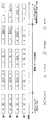
コアネットワーク(CN)は、mute()関数を用いることによって、ミュートシグナリングを介して、Ωで表される一組の基地局に、Ψ内に定義されている特定のダウンリンク又はアップリンクインターバルをシャットダウンするように要求できる。幾つかの実施例では、1つ以上のミュートインターバルを開始する、mute(Ω,Ψ)と呼ばれる関数は、以下のように定義することができる。コアネットワークは、バックホールネットワークを介して、Ω内の全ての基地局に、Ψを含むミュート要求(Mute Request)を送信することができる。基地局は、コアネットワークからミュート要求(Mute Request)を受信すると、D/U割当テーブルと共にΨを含むミュートインターバルシグナリングを送信でき、ミュートインターバルシグナリングが遅延ありのミュートであると解釈された場合、状態B2になり、ミュートインターバルシグナリングが即座のミュートであると解釈された場合、状態B3になる。ミュート要求(Mute Request)の受信とミュートインターバルシグナリングの送信との間の遅延は、基地局がローカルストラテジに基づいて決定する。一旦、状態B2の基地局が(スケジューラを介して)ミュートされたインターバル内で送信されている無線信号がないことを感知すると、基地局は、ミュート応答(Mute Response)をコアネットワークに送信して状態B3になる。ユーザ設備は、非ゼロミュートインターバルシグナリングを受信すると、ミュートインターバルシグナリングが遅延ありのミュートであると解釈された場合、状態A2になり、ミュートインターバルシグナリングが即座のミュートであると解釈された場合、状態A3になる。状態A2のユーザ設備において、これらのミュートインターバルの間、無線信号の送信も受信もなくなると、ユーザ設備は、状態A3になる。 The core network (CN) uses a mute () function to send a specific downlink or uplink interval defined in Ψ to a set of base stations represented by Ω via mute signaling. You can request to shut down. In some embodiments, a function called mute (Ω, Ψ) that starts one or more mute intervals can be defined as follows: The core network can transmit a mute request including Ψ to all base stations in Ω via the backhaul network. When the base station receives a mute request from the core network, the base station can transmit mute interval signaling including Ψ together with the D / U allocation table, and if the mute interval signaling is interpreted as mute with delay, If it becomes B2 and the mute interval signaling is interpreted as an immediate mute, state B3 is entered. The delay between the reception of the mute request and the transmission of the mute interval signaling is determined by the base station based on the local strategy. Once the base station in state B2 senses that there is no radio signal being transmitted within the muted interval (via the scheduler), the base station sends a mute response to the core network. It will be in state B3. When the user equipment receives the non-zero mute interval signaling, it enters state A2 if the mute interval signaling is interpreted as a mute with delay, and if the mute interval signaling is interpreted as an immediate mute, It becomes A3. If the user equipment in state A2 loses transmission and reception of radio signals during these mute intervals, the user equipment enters state A3.
コアネットワーク(CN)は、Ωによって表される一組の基地局に対して、Ψ内に定義されているmute_recover()関数を用いて、1つ以上の特定のミュートされたインターバルをダウンリンク/アップリンクスロット又はシンボルに回復するように要求することができる。幾つかの実施例では、1つ以上のミュートインターバルから回復する、mute_recover(Ω,Ψ)と呼ばれる関数は、以下のように定義することができる。コアネットワークは、Ω内の全ての基地局にΨ(又は同等な新たなD/U割当テーブル)を含むMute_Recoverコマンドを送信することができる。基地局は、このコマンドを受信すると、新たなD/U割当テーブルを取得し、新たなミュートインターバルシグナリングと共にこれを送信し、新たなミュートインターバルシグナリングは、ゼロミュートインターバルシグナリングであってもよい。Mute_Recoverコマンドの受信と新たなミュートインターバルシグナリングの送信との間の遅延は、基地局がローカルストラテジに基づいて決定する。一方、基地局は、新たなD/U割当テーブルを現在のD/U割当テーブルとして扱うことができ、新たなミュートインターバルシグナリング内でミュートされていないインターバルの間、無線信号の送信を再開することができる。これにより、無線フレーム内に更なるミュートインターバルがなければ、基地局は、状態B1に戻る。幾つかの実施例では、基地局は、コアネットワークにミュート回復確認(Mute_Recover Confirmation)を送信して、基地局の現在のD/U割当テーブルを確認する。UEは、新たなミュートインターバルシグナリングを受信した後、無線フレーム内に更なるミュートインターバルがなければ、状態A1に戻る。幾つかの実施例では、ミュートインターバルの生成及び除去は、基地局間で非同期的に行われる。 The core network (CN) uses a mute_recover () function defined in Ψ for a set of base stations represented by Ω to downlink / mute one or more specific muted intervals. It may be requested to recover to an uplink slot or symbol. In some embodiments, a function called mute_recover (Ω, Ψ) that recovers from one or more mute intervals may be defined as follows: The core network can send a Mute_Recover command containing Ψ (or an equivalent new D / U allocation table) to all base stations in Ω. When the base station receives this command, it obtains a new D / U allocation table and transmits it along with the new mute interval signaling, and the new mute interval signaling may be zero mute interval signaling. The delay between receiving the Mute_Recover command and sending a new mute interval signaling is determined by the base station based on the local strategy. On the other hand, the base station can treat the new D / U allocation table as the current D / U allocation table, and resume transmission of radio signals during an interval that is not muted in the new mute interval signaling. Can do. Thus, if there is no further mute interval in the radio frame, the base station returns to state B1. In some embodiments, the base station sends a mute recovery confirmation (Mute_Recover Confirmation) to the core network to confirm the current D / U allocation table of the base station. After receiving a new mute interval signaling, the UE returns to state A1 if there is no further mute interval in the radio frame. In some embodiments, muting intervals are generated and removed asynchronously between base stations.
図7A、図7B、図8A、図8B、図9A及び図9Bは、ここに、説明する技術の実現のための異なる処理及びネットワークフローの具体例を示している。これらの図面は、上述した表1に対応している。図7A、図7Bは、基地局内におけるミュートインターバルの処理の異なる具体例を示している。図7Aは、遅延ありのミュート技術を用いる有限状態機械(finite state machine:FSM)の状態及びこれらの状態の間の遷移を示している。図7Bは、即座のミュート技術を用いる有限状態機械の状態及びこれらの状態の間の遷移を示している。図8A及び図8Bは、ユーザ設備等の移動機器におけるミュートインターバルの処理の異なる具体例を示している。図8Aは、遅延ありのミュート技術を用いる有限状態機械(finite state machine:FSM)の状態及びこれらの状態の間の遷移を示している。図8Bは、即座のミュート技術を用いる有限状態機械の状態及びこれらの状態の間の遷移を示している。図9A及び図9Bは、ミュート(mute)及びミュート回復(mute recover)関数についてのネットワークフローの異なる具体例を示している。図9Aは、遅延ありのミュートについての例示的なフローを示している。図9Bは、即座のミュートについての例示的なフローを示している。 7A, 7B, 8A, 8B, 9A, and 9B show specific examples of different processes and network flows for realizing the technology described here. These drawings correspond to Table 1 described above. FIG. 7A and FIG. 7B show specific examples of different processing of the mute interval in the base station. FIG. 7A shows the states of a finite state machine (FSM) using a mute technique with delay and the transitions between these states. FIG. 7B shows the states of the finite state machine using the immediate mute technique and the transitions between these states. 8A and 8B show specific examples of different mute interval processing in a mobile device such as user equipment. FIG. 8A shows the states of a finite state machine (FSM) using a mute technique with delay and the transitions between these states. FIG. 8B shows the states of the finite state machine using the immediate mute technique and the transitions between these states. FIG. 9A and FIG. 9B show different examples of network flows for mute and mute recover functions. FIG. 9A shows an exemplary flow for mute with delay. FIG. 9B shows an exemplary flow for immediate mute.
無線通信システムは、異なる状況毎にミュートインターバル及び関連する動作規則及び関数を使用することができる。例えば、システムは、ここに説明した技術を用いて、古いD/U割当比を新たなD/U割当比に切り替えることができる。他の具体例では、システムは、ここに説明した技術を用いて、1つのサービス領域のD/U割当比を、隣接する領域のD/U割当比とは異なるように維持する。 A wireless communication system may use a mute interval and associated operating rules and functions for different situations. For example, the system can switch an old D / U allocation ratio to a new D / U allocation ratio using the techniques described herein. In another implementation, the system maintains the D / U allocation ratio of one service area different from the D / U allocation ratio of adjacent areas using the techniques described herein.
無線通信システムは、D/U割当比に対する複数の調整を実行して、ターゲットD/U割当比を達成することができる。例えば、TDD無線システムは、ND:NUによって特定されるD/U割当比を有することができ、ここで、N=ND+NUは、スロット−TDDフレーム構造では、1フレームあたりのデータスロットの総数であり、シンボル−TDDフレーム構造では、1フレームあたりのデータシンボルの総数である。TDDシステムは、(ND+N0):(NU−N0)によって特定されるターゲットD/U比に変更する必要がある。換言すれば、システムは、N0個のアップリンクスロット又はシンボルをダウンリンクスロット又はシンボルに切り替える必要がある。D/U比を(ND−N0):(NU+N0)に変更する手続きは、D/U比を(ND+N0):(NU−N0)に変更する手続きと同様である。ターゲットD/U比は、マルチステップ調整スキーム(multi-step adjustment scheme)によって達成できる。マルチステップ調整スキームは、システムの効率を高めることができ、システム容量の最大瞬間損失(maximum instant loss)と、このD/U比調整に費やされる合計時間との間のトレードオフを最適にする。The wireless communication system may perform multiple adjustments to the D / U allocation ratio to achieve the target D / U allocation ratio. For example, a TDD radio system may have a D / U allocation ratio specified by ND : NU , where N = ND + NU is the data per frame in the slot-TDD frame structure. The total number of slots, and in the symbol-TDD frame structure, the total number of data symbols per frame. The TDD system needs to be changed to the target D / U ratio specified by (ND + N0 ) :( NU −N0 ). In other words, the system needs to switch N0 uplink slots or symbols to downlink slots or symbols. The procedure for changing the D / U ratio to (ND −N0 ) :( NU + N0 ) is the same as the procedure for changing the D / U ratio to (ND + N0 ) :( NU −N0 ). It is. The target D / U ratio can be achieved by a multi-step adjustment scheme. A multi-step adjustment scheme can increase the efficiency of the system, optimizing the trade-off between maximum instantaneous loss of system capacity and the total time spent on this D / U ratio adjustment.
図10は、スロットベースのフレーム構造のためのマルチステップD/U比調整におけるシングルステップの変更の具体例を示している。図11は、シンボルベースのフレーム構造のためのマルチステップD/U比調整におけるシングルステップの変更の具体例を示している。これらの2つの図面では、基地局間の非同期動作が確認される。 FIG. 10 shows a specific example of the single step change in the multi-step D / U ratio adjustment for the slot-based frame structure. FIG. 11 shows a specific example of the single step change in the multi-step D / U ratio adjustment for the symbol-based frame structure. In these two drawings, the asynchronous operation between the base stations is confirmed.
無線通信システムは、1つのサービス領域のD/U割当比を、隣接する領域のD/U割当比とは異なるように維持できる。時点Aと時点Bとの間の持続時間に亘って総システム容量損失を拡散することによって、時点Aから時点BにD/U比を変更するKステップ調整アルゴリズムと同様に、K層D/U比調整法(K-tier D/U ratio adjustment method)は、異なる基地局に亘ってシステム容量損失を拡散することができる。K層D/U比調整法は、サービス領域A内のD/U比をサービス領域BのD/U比とは異なるように維持できる。 The wireless communication system can maintain the D / U allocation ratio of one service area different from the D / U allocation ratio of adjacent areas. Similar to the K step adjustment algorithm that changes the D / U ratio from time A to time B by spreading the total system capacity loss over the duration between time A and time B The K-tier D / U ratio adjustment method can spread system capacity loss across different base stations. The K layer D / U ratio adjustment method can maintain the D / U ratio in the service area A different from the D / U ratio in the service area B.
無線通信システムは、K層D/U比調整を実行できる。TDD無線システムは、ND:NUによって特定されるD/U割当比を有することができ、ここで、N=ND+NUは、スロット−TDDフレーム構造では、1フレームあたりのデータスロットの総数であり、シンボル−TDDフレーム構造では、1フレームあたりのデータシンボルの総数である。TDDシステムは、ある領域内のD/U比を(ND+N0):(NU−N0)に変更でき、すなわち、N0個のアップリンクスロット又はシンボルをダウンリンクに切り替えることができる。D/U比を(ND−N0):(NU+N0)に変更する場合も、D/U比を(ND+N0):(NU−N0)に変更する場合と同様である。The wireless communication system can perform K layer D / U ratio adjustment. A TDD radio system may have a D / U allocation ratio specified by ND : NU , where N = ND + NU is the number of data slots per frame in the slot-TDD frame structure. In the symbol-TDD frame structure, the total number of data symbols per frame. The TDD system can change the D / U ratio in a region to (ND + N0 ) :( NU −N0 ), ie, switch N0 uplink slots or symbols to the downlink. . Changing the D / U ratio to (ND −N0 ) :( NU + N0 ) is the same as changing the D / U ratio to (ND + N0 ) :( NU −N0 ). It is.
図12は、異なるD/U割当比を有する多層レイアウトマップの具体例を示している。マップは、コアネットワークによって制御される異なるサービス領域を含む。この具体例では、初期的には、全体のサービス領域が同じD/U割当比を有する。層3領域のD/U比を高めるために、K=3層のレイアウトを生成し、層0から層3に向かって、層毎にD/U比を高める。図13及び図14は、この具体例のためのK層調整法を示している。図13は、スロットベースのフレーム構造のためのK層D/U比調整アルゴリズムの具体例を示している。図14は、スロットベースのフレーム構造のためのK層D/U比調整アルゴリズムの具体例を示している。 FIG. 12 shows a specific example of a multilayer layout map having different D / U allocation ratios. The map includes different service areas that are controlled by the core network. In this specific example, initially, the entire service area has the same D / U allocation ratio. In order to increase the D / U ratio of the
図15は、TDD無線通信システム等の無線通信システムの具体例を示している。システム1500は、加入者局、移動局、ユーザ設備、無線エアカード、携帯電話、他の無線機器等の1つ以上の移動機器1505と通信するための基地局(BS)1510のネットワークを含むことができる。幾つかの実施例では、移動機器は、例えば、無線エアカードを有するデスクトップコンピュータ等、固定された位置を有していてもよい。コアネットワーク1515は、1つ以上の基地局1510を制御する1つ以上のコントローラを含むことができる。コントローラは、例えば、プロセッサ又は専用論理回路等のプロセッサ電子回路を含むことができる。コントローラの機能は、コアネットワーク1515内で複数のコンポーネントに分散させてもよい。 FIG. 15 shows a specific example of a wireless communication system such as a TDD wireless communication system.
移動機器1505は、移動ユニットであっても固定ユニットであってもよい。固定ユニットは、システム100のカバレッジ領域内のどこに配置及び/又は再配置してもよい。固定ユニットの無線機器には、例えば、デスクトップコンピュータ及びコンピュータサーバが含まれる。移動ユニットには、例えば、携帯電話、携帯情報端末(Personal Digital Assistant:PDA)、移動機器及びモバイルコンピュータが含まれる。 The
システム1500の基地局1510は、無線送受信機を備えていてもよい。基地局1510は、ダウンリンク無線信号を介して、移動機器1505に信号を送信することができる。システム1500の移動機器1505は、無線送受信機を備えていてもよい。移動機器1505は、アップリンク無線信号を介して、基地局1505に信号を送信することができる。
図16は、無線局のアーキテクチャの具体例を示している。無線局1605、例えば、基地局又は移動機器は、プロセッサ電子回路1610を含むことができる。プロセッサ電子回路1610は、ここに説明した1つ以上の演算又は技術を実行するように構成された処理ユニットを含むことができる。処理ユニットは、1つ以上の専用の又は汎用のプロセッサ、及び/又は専用の論理回路を含むことができる。無線局1605は、アンテナ1620等の通信インタフェースを介して、無線信号を送信及び/又は受信するための送受信機電子回路1615を含むことができる。無線局1605は、データを送信及び受信するための他の通信インタフェースを含むことができる。幾つかの実施例では、処理ユニットが送受信機の機能の一部又は全部を担うように構成してもよい。 FIG. 16 shows a specific example of the architecture of a radio station. A
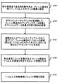
図17Aは、基地局上でのミュート動作の例示的処理を示している。1705では、時分割復信で基地局を動作させ、フレーム構造を用いて、1つ以上の移動機器と通信させる。基地局は、1710において、ダウンリンク−アップリンク比を調整して、フレーム構造内のアップリンクデータ容量とダウンリンクデータ容量との間で割当を変更できる。幾つかの実施例では、コアネットワークが基地局を制御して、調整を行うことができる。 FIG. 17A shows an exemplary process of a mute operation on the base station. At 1705, the base station is operated in time division duplex and communicated with one or more mobile devices using a frame structure. The base station can adjust the downlink-uplink ratio at 1710 to change the allocation between uplink data capacity and downlink data capacity in the frame structure. In some embodiments, the core network may control the base station to make adjustments.
基地局は、1715において、調整されたダウンリンク−アップリンク比に基づいて、ミュートインターバルを決定でき、ミュートインターバルは、フレーム構造の1つ以上の領域を含むことができる。ミュートインターバルの決定は、フレーム構造内でミュートインターバルとしてアップリンク又はダウンリンクインターバルを選択することを含むことができる。幾つかの実施例では、ミュートインターバルは、フレーム構造内の1つ以上のスロットを含むことができる。幾つかの実施例では、ミュートインターバルは、フレーム構造内の1つ以上のシンボルを含むことができる。ミュートインターバルは、フレーム構造に隣接する又は隣接しない領域を含むことができる。 The base station may determine a mute interval at 1715 based on the adjusted downlink-uplink ratio, and the mute interval may include one or more regions of the frame structure. Determining the mute interval may include selecting an uplink or downlink interval as the mute interval within the frame structure. In some embodiments, the mute interval may include one or more slots in the frame structure. In some embodiments, the mute interval may include one or more symbols in the frame structure. The mute interval can include regions that are adjacent or not adjacent to the frame structure.
基地局は、1720において、割当の変更によって影響があるフレーム構造の1つ以上の領域を特定するミュート情報を生成できる。基地局は、1725において、1つ以上の移動機器にミュート情報を送信することができる。幾つかの実施例では、基地局は、1つ以上の移動機器にD/U割当テーブル及びミュート情報を含むデータを送信することができる。幾つかの実施例では、D/U割当テーブル及びミュート情報を結合できる。 The base station can generate mute information at 1720 that identifies one or more regions of the frame structure that are affected by the change in assignment. The base station may transmit mute information at 1725 to one or more mobile devices. In some embodiments, the base station can transmit data including a D / U allocation table and mute information to one or more mobile devices. In some embodiments, the D / U allocation table and mute information can be combined.
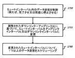
図17Bは、基地局におけるミュート動作の例示的処理を示している。基地局は、1750において、ミュートインターバル内のデータ送信を制御でき、例えば、データ送信を完了させ又は即座に停止するように制御できる。基地局は、1755において、調整されたダウンリンク−アップリンク比に基づいて、ミュートインターバルをアップリンクインターバル又はダウンリンクインターバルに変更することができる。幾つかの実施例では、基地局は、ミュートインターバルと共にアクティビティを監視でき、アクティビティが停止した後、基地局は、ミュートインターバルをアップリンクインターバル又はダウンリンクインターバルに変更することができる。基地局は、1760において、変更されたミュートインターバル、例えば、新たなアップリンクインターバル又はダウンリンクインターバルについて、1つ以上のデータ送信をスケジューリングできる。 FIG. 17B shows an exemplary process of a mute operation in the base station. The base station may control data transmission within a mute interval at 1750, eg, complete or stop data transmission immediately. The base station may change the mute interval to an uplink interval or a downlink interval at 1755 based on the adjusted downlink-uplink ratio. In some embodiments, the base station can monitor activity along with the mute interval, and after the activity stops, the base station can change the mute interval to an uplink interval or a downlink interval. The base station may schedule one or more data transmissions at 1760 for a modified mute interval, eg, a new uplink interval or downlink interval.
図18は、移動機器上のミュート動作の例示的処理を示している。移動機器は、1805において、時分割複信を用いて、フレーム構造及び第1の割当を使用して基地局と通信する。フレーム構造は、アップリンクデータ領域及びダウンリンクデータ領域を含むことができる。第1の割当は、アップリンク領域の総サイズ及びダウンリンク領域の総サイズを含むことができる。移動機器は、1810において、フレーム構造の特定の領域のミュートアクティビティを示すミュート情報を受信することができる。特定の領域は、1つ以上のスロット又は1つ以上のシンボルを含むことができる。特定の領域内の複数のスロットは、フレーム構造内で隣接していてもよく、隣接していなくてもよい。ミュート情報は、第1の割当とは異なる第2の割当を示していてもよい。 FIG. 18 illustrates an exemplary process for a mute operation on a mobile device. The mobile device communicates with the base station at 1805 using time division duplex using the frame structure and the first assignment. The frame structure may include an uplink data area and a downlink data area. The first allocation may include the total size of the uplink region and the total size of the downlink region. The mobile device can receive mute information at 1810 indicating mute activity for a particular region of the frame structure. A particular region can include one or more slots or one or more symbols. A plurality of slots in a specific region may or may not be adjacent in the frame structure. The mute information may indicate a second assignment different from the first assignment.
移動機器は、1815において、第1の割当に基づいて、特定の領域に関連する動作を完了でき、及び1820において、第2の割当を用いる動作を開始できる。例えば、移動局は、動作を完了でき、例えば、特定の領域内でのデータの送信を停止でき、及び第2の割当を用いる動作、例えば、特定の領域内でのデータの受信を開始することができる。他の具体例では、移動局は、例えば、特定の領域において送信されたデータの受信等の動作を完了でき、及び第2の割当を用いて、特定の領域におけるデータの送信等の動作を開始することができる。 The mobile device can complete an operation associated with a particular region based on the first assignment at 1815 and can begin an operation using the second assignment at 1820. For example, the mobile station can complete the operation, for example, can stop transmitting data within a specific region, and can start to receive data within a specific region, for example, an operation using a second allocation. Can do. In another specific example, the mobile station can complete an operation such as reception of data transmitted in a specific area, for example, and uses the second allocation to start an operation such as transmission of data in the specific area. can do.
幾つかの実施例では、基地局とユーザ設備との間の通信リンクを確立することができ(通信リンクは、基地局がユーザ設備に送信を行うダウンリンクインターバルと、ユーザ設備が基地局に送信を行うアップリンクインターバルとの第1のフレームを含んでいてもよい)、第1のフレームのダウンリンクインターバルにおいて、ミュートインターバルの位置を送信することができる。前フレームからのダウンリンクインターバル又はアップリンクインターバルをミュートインターバルに置換して、ダウンリンク−アップリンク割当比を変更することができる。 In some embodiments, a communication link can be established between the base station and the user equipment (the communication link is a downlink interval at which the base station transmits to the user equipment, and the user equipment transmits to the base station). And the position of the mute interval can be transmitted in the downlink interval of the first frame. The downlink-uplink allocation ratio can be changed by replacing the downlink interval or uplink interval from the previous frame with a mute interval.
幾つかの実施例では、スロット−TDDフレーム構造のミュートスロット又はシンボル−TDDフレーム構造のミュートシンボルに対応するミュートインターバルを用いて、インターバルの間の全ての無線送信の停止を指示することができる。基地局は、スロットマスク法を用いて、スロット−TDDフレーム構造におけるミュートスロットをユーザ設備にシグナリングすることができる。基地局は、スロットリスト法を用いて、スロット−TDDフレーム構造におけるミュートスロットをユーザ設備にシグナリングすることができる。基地局は、シンボルセット法を用いて、シンボル−TDDフレーム構造におけるミュートシンボルをユーザ設備にシグナリングすることができ、ここで、シンボル−TDDフレーム構造内において、ミュートシンボルが連続することによって形成されるミュートインターバルは、ガード期間に隣接する。基地局は、定義済み割当テーブルエントリ法を用いて、スロット−TDDフレーム構造のミュートスロット及びシンボル−TDDフレーム構造のミュートシンボルをユーザ設備にシグナリングすることができる。 In some embodiments, a mute interval corresponding to a mute slot in a slot-TDD frame structure or a mute symbol in a symbol-TDD frame structure may be used to indicate a stop of all radio transmissions during the interval. The base station can signal the mute slot in the slot-TDD frame structure to the user equipment using the slot mask method. The base station can signal the mute slot in the slot-TDD frame structure to the user equipment using the slot list method. The base station can use the symbol set method to signal the mute symbol in the symbol-TDD frame structure to the user equipment, where the mute symbol is formed by successive symbols in the symbol-TDD frame structure. The mute interval is adjacent to the guard period. The base station can signal the mute slot of the slot-TDD frame structure and the mute symbol of the symbol-TDD frame structure to the user equipment using the predefined allocation table entry method.
幾つかの実施例では、ネットワーク関数mute()は、基地局からユーザ設備への非ゼロミュートインターバルシグナリングを含むことができる。ネットワーク関数mute()は、コアネットワークから基地局へのミュート要求(Mute Request)及び基地局からコアネットワークへのミュート応答(Mute Response)を含むことができる。ネットワーク関数mute_recover()は、基地局からユーザ設備へのゼロミュートインターバルシグナリングを含むことができる。ネットワーク関数mute_recover()は、コアネットワークから基地局へのミュート回復コマンド(Mute Recover Command)及び基地局からコアネットワークへのオプションのミュート回復確認(Mute Recover Confirmation)を含むことができる。 In some embodiments, the network function mute () may include non-zero mute interval signaling from the base station to the user equipment. The network function mute () can include a mute request from the core network to the base station and a mute response from the base station to the core network. The network function mute_recover () may include zero mute interval signaling from the base station to the user equipment. The network function mute_recover () may include a mute recovery command from the core network to the base station and an optional mute recovery confirmation from the base station to the core network.
幾つかの実施例では、KステップD/U比調整アルゴリズムを用いて、ネットワーク内のD/U割当比を動的に変更することができる。K層D/U比調整アルゴリズムを用いて、1つの領域のD/U割当比を他の領域のD/U割当比とは異なるように維持できる。 In some embodiments, a K-step D / U ratio adjustment algorithm can be used to dynamically change the D / U allocation ratio in the network. Using the K layer D / U ratio adjustment algorithm, the D / U allocation ratio of one area can be maintained different from the D / U allocation ratio of the other area.
上述した技術を用いて、例えば、(1)ネットワークが古いD/U割当比を新たな値に切り替える必要があるシナリオ、及び(2)ネットワークが1つのサービス領域のD/U割当比を隣接する領域のD/U割当比とは異なるように維持する必要があるシナリオにおいて、ダウンリンク−アップリンク割当比を動的に変更することができる。様々な実施例において、D/U割当比の動的な変更の間、基地局間で切替動作を同期させることを不要にすること、ネットワークオペレータによる制御に基づいて、ネットワークの観点から割込みフレームなしで、瞬間システム容量損失を最小化すること、ユーザトラヒックへの割込みを最小化又は排除すること、及びスロット−TDDフレーム構造及びシンボル−TDDフレーム構造の両方に上述した技術を適用することを含む特徴の1つ以上を達成できる。 Using the techniques described above, for example, (1) a scenario where the network needs to switch the old D / U allocation ratio to a new value, and (2) the network adjoins the D / U allocation ratio of one service area. In scenarios that need to be kept different from the D / U allocation ratio of the region, the downlink-uplink allocation ratio can be changed dynamically. In various embodiments, there is no need to synchronize switching operations between base stations during dynamic change of D / U allocation ratio, no interrupt frames from the network point of view based on control by the network operator Features including minimizing instantaneous system capacity loss, minimizing or eliminating interruption to user traffic, and applying the techniques described above to both slot-TDD and symbol-TDD frame structures. One or more of can be achieved.
ここに開示した実施の形態及び他の実施の形態、並びに本明細書において説明した機能的動作は、デジタル電子回路で実現してもよく、本明細書に開示した構造及びこれらの構造的な均等物を含むコンピュータソフトウェア、ファームウェア又はハードウェアで実現してもよく、これらの1つ以上の組合せで実現してもよい。ここに開示した実施の形態及び他の実施の形態は、1つ以上のコンピュータプログラム製品、すなわち、コンピュータが読取可能な媒体内に符号化され、データ処理装置によって実行され、又はデータ処理装置の動作を制御するコンピュータプログラム命令の1つ以上のモジュールとして実現することもできる。コンピュータが読取可能な媒体は、機械可読のストレージデバイス、機械可読のストレージ基板、メモリデバイス、機械可読の伝播信号に作用する組成物又はこれらの1つ以上の組合せであってもよい。用語「データ処理装置」は、データを処理するための全ての装置、デバイス及び機械を包含し、一例としてプログラミング可能なプロセッサ、コンピュータ、複数のプロセッサ又はコンピュータがこれに含まれる。装置は、ハードウェアに加えて、当該コンピュータプログラムの実行環境を作成するコード、例えば、プロセッサファームウェアを構成するコード、プロトコルスタック、データベース管理システム、オペレーティングシステム又はこれらの1つ以上の組合せを含むことができる。伝播信号は、人工的に生成された信号であり、例えば、適切な受信装置への送信のために情報を符号化するように機械が生成した電気信号、光信号又は電磁波信号である。 The embodiments disclosed herein and other embodiments, as well as the functional operations described herein, may be implemented with digital electronic circuitry and may include structures disclosed herein and their structural equivalents. It may be realized by computer software, firmware, or hardware including an object, or may be realized by a combination of one or more of these. The disclosed embodiments and other embodiments can be encoded in one or more computer program products, ie, computer readable media, executed by a data processing device, or operations of a data processing device. It can also be implemented as one or more modules of computer program instructions that control The computer readable medium may be a machine readable storage device, a machine readable storage substrate, a memory device, a composition that acts on a machine readable propagation signal, or a combination of one or more thereof. The term “data processing device” encompasses all devices, devices, and machines for processing data, including by way of example a programmable processor, computer, multiple processors or computers. In addition to hardware, the apparatus may include code for creating an execution environment of the computer program, for example, code constituting processor firmware, a protocol stack, a database management system, an operating system, or a combination of one or more of these. it can. A propagated signal is an artificially generated signal, for example, an electrical signal, an optical signal, or an electromagnetic wave signal generated by a machine to encode information for transmission to a suitable receiving device.
コンピュータプログラム(プログラム、ソフトウェア、ソフトウェアアプリケーション、スクリプト又はコードとも呼ばれる。)は、コンパイラ言語又はインタープリタ言語を含む如何なる形式のプログラミング言語で書いてもよく、例えば、スタンドアロンプログラムとして、若しくはモジュール、コンポーネント、サブルーチン又は演算環境での使用に適する他のユニットとして、如何なる形式で展開してもよい。コンピュータプログラムは、必ずしもファイルシステム内のファイルに対応していなくてもよい。プログラムは、他のプログラム又はデータを含むファイル(例えば、マークアップ言語文書内に保存された1つ以上のスクリプト)の一部に保存してもよく、当該プログラムに専用の単一のファイルに保存してもよく、連携する複数のファイル(例えば、モジュール、サブプログラム又はコードの一部を保存する1つ以上のファイル)に保存してもよい。コンピュータプログラムは、1つのコンピュータ上で実行されるように展開してもよく、1つの場所に設けられた又は複数の場所に亘って分散され、通信ネットワークによって相互接続された複数のコンピュータ上で実行されるように展開してもよい。 A computer program (also called a program, software, software application, script or code) may be written in any form of programming language, including a compiler language or an interpreter language, for example as a stand-alone program or as a module, component, subroutine or As other units suitable for use in a computing environment, they may be deployed in any form. A computer program does not necessarily correspond to a file in a file system. The program may be stored in a part of a file containing other programs or data (eg, one or more scripts stored in a markup language document) and stored in a single file dedicated to that program Alternatively, the files may be stored in a plurality of files to be linked (for example, one or more files storing a module, a subprogram, or a part of code). A computer program may be deployed to be executed on a single computer, and may be executed on a plurality of computers provided at one location or distributed across multiple locations and interconnected by a communication network May be deployed as is.
本明細書に開示したプロセス及びロジックフローは、入力データを処理し、出力を生成することによって機能を実現する1つ以上のコンピュータプログラムを実行する1つ以上のプログラミング可能なプロセッサによって実現してもよい。プロセス及びロジックフローは、例えば、フィールドプログラマブルゲートアレイ(field programmable gate array:FPGA)又は特定用途向け集積回路(application specific integrated circuit:ASIC)等の専用論理回路によって実行してもよい。 The processes and logic flows disclosed herein may be implemented by one or more programmable processors that execute one or more computer programs that implement functions by processing input data and generating output. Good. The process and logic flow may be performed by a dedicated logic circuit such as, for example, a field programmable gate array (FPGA) or an application specific integrated circuit (ASIC).
コンピュータプログラムの実行に適するプロセッサには、一例として、汎用マイクロプロセッサ及び専用マイクロプロセッサの両方、並びにあらゆる種類のデジタルコンピュータの1つ以上のプロセッサの何れも含まれる。プロセッサは、通常、読出専用メモリ又はランダムアクセスメモリ、若しくはこれらの両方から命令及びデータを受け取る。コンピュータの基本的な要素は、命令を実行するためのプロセッサ、並びに命令及びデータを保存する1つ以上の記憶装置である。また、コンピュータは、通常、データを保存するための1つ以上の大容量記憶装置、例えば、磁気ディスク、光磁気ディスク又は光ディスクを含み、若しくは、大容量記憶装置からデータを受信し、大容量記憶装置にデータを送信し、又はこの両方の動作を行うように大容量記憶装置に動作的に接続されている。但し、コンピュータは、必ずしもこのような装置を有する必要はない。コンピュータプログラム命令及びデータの格納に適するデバイスには、一例として挙げれば、半導体記憶デバイス、例えば、EPROM、EEPROM及びフラッシュメモリデバイスを含む全ての形式の不揮発性メモリ、磁気ディスク、例えば、内蔵ハードディスク又はリムーバブルディスク、光磁気ディスク、並びにCD−ROMディスク及びDVD−ROMディスク等が含まれる。プロセッサ及びメモリは、専用論理回路によって補ってもよく、専用論理回路に組み込んでもよい。 Processors suitable for executing computer programs include, by way of example, both general and special purpose microprocessors, as well as any one or more processors of any kind of digital computer. A processor typically receives instructions and data from a read-only memory or a random access memory or both. The basic elements of a computer are a processor for executing instructions and one or more storage devices for storing instructions and data. The computer also typically includes one or more mass storage devices for storing data, eg, a magnetic disk, magneto-optical disk or optical disk, or receives data from the mass storage device and stores mass data. It is operatively connected to the mass storage device to transmit data to the device or to perform both operations. However, the computer does not necessarily have such a device. Devices suitable for storage of computer program instructions and data include, by way of example, semiconductor storage devices such as all types of non-volatile memory including EPROM, EEPROM and flash memory devices, magnetic disks such as internal hard disks or removable devices. Discs, magneto-optical discs, CD-ROM discs and DVD-ROM discs are included. The processor and the memory may be supplemented by a dedicated logic circuit or may be incorporated in the dedicated logic circuit.
本明細書は、多くの詳細事項を含んでいるが、これらの詳細事項は、特許請求している又は特許請求することができる本発明の範囲を限定するものとは解釈されず、本発明の特定の実施の形態の特定の特徴の記述として解釈される。本明細書おいて、別個の実施の形態の文脈で開示した幾つかの特徴を組み合わせて、単一の実施の形態として実現してもよい。逆に、単一の実施の形態の文脈で開示した様々な特徴は、複数の実施の形態に別個に具現化してもよく、適切な如何なる部分的組合せとして具現化してもよい。更に、以上では、幾つかの特徴を、ある組合せで機能するものと説明しているが、初期的には、そのように特許請求している場合であっても、特許請求された組合せからの1つ以上の特徴は、幾つかの場合、組合せから除外でき、特許請求された組合せは、部分的組合せ又は部分的な組合せの変形に変更してもよい。同様に、図面では、動作を特定の順序で示しているが、このような動作は、所望の結果を達成するために、図示した特定の順序又は順次的な順序で行う必要はなく、また、図示した全ての動作を行う必要もない。 This specification includes many details, but these details are not to be construed as limiting the scope of the invention as claimed or claimable. To be construed as a description of particular features of a particular embodiment. In this specification, several features disclosed in the context of separate embodiments may be combined and implemented in a single embodiment. Conversely, various features disclosed in the context of a single embodiment can be embodied separately in multiple embodiments and can be embodied in any suitable subcombination. Furthermore, although the above describes some features as functioning in a certain combination, initially, even if so claimed, from the claimed combination One or more features may be excluded from the combination in some cases, and the claimed combination may be changed to a partial combination or a variation of a partial combination. Similarly, in the drawings, the operations are shown in a particular order, but such operations need not be performed in the particular order or sequential order shown to achieve the desired result, and It is not necessary to perform all the operations shown.
幾つかの具体例及び実施例のみを開示した。ここに開示した内容に基づいて、上述した具体例及び実施例及び他の実施例を変形、変更及び拡張することができる。例えば、幾つかの無線システムでは、上述した側面について異なる用語を用いることがある。例えば、幾つかの無線システムでは、スロットは、サブフレーム又はフレームと呼ばれ、又はサブフレーム又はフレームを含む。更に、幾つかの無線システムでは、スロットは、フレームを含み、スーパーフレーム(superframe)は、複数のこのようなスロットを含むことができる。異なるTDDシステムは、上述した技術について、異なるプロトコル解釈を有することができる。 Only a few specific examples and examples have been disclosed. Based on the content disclosed here, the above-described specific examples, examples, and other examples can be modified, changed, and extended. For example, some wireless systems may use different terminology for the aspects described above. For example, in some wireless systems, a slot is referred to as or includes a subframe or frame. Further, in some wireless systems, a slot includes a frame, and a superframe can include a plurality of such slots. Different TDD systems can have different protocol interpretations for the techniques described above.
Claims (60)
Translated fromJapanese基地局において、当該基地局とユーザ設備との間で、前記基地局が前記ユーザ設備に送信を行うダウンリンクインターバルと、前記ユーザ設備が前記基地局に送信を行うアップリンクインターバルとを含む通信リンクを確立するステップと、
前記基地局において、ミュートインターバルを生成し、前フレームにおけるダウンリンクインターバル又はアップリンクインターバルを前記ミュートインターバルで置換して、次フレームのダウンリンク−アップリンク割当比を変更するステップと、
前記基地局が、フレーム構造を用いて、前記ミュートインターバルの位置を前記ユーザ設備に送信するステップとを有する方法。In the method of dynamically changing the downlink-uplink allocation,
In the base station, a communication link including a downlink interval in which the base station transmits to the user equipment and an uplink interval in which the user equipment transmits to the base station between the base station and the user equipment. Establishing steps,
In the base station, generating amute interval, replacing the downlink interval or uplink interval in the previous frame with themute interval, and changing the downlink-uplink allocation ratio of the next frame;
The base station transmitting a position of the mute interval to the user equipment using a frame structure.
前記基地局を動作させ、前記ミュートスロット内のデータ送信を完了させ又は即座に停止させるステップとを更に有する請求項6記載の方法。Changing a downlink slot in the frame structure to the mute slot;
The method of claim 6, further comprising the step of operating the base station to complete or immediately stop data transmission in the mute slot.
前記ユーザ設備を制御し、前記アップリンクスロット内で送信を行わせるステップとを更に有する請求項7記載の方法。Changing the mute slot to an uplink slot;
8. The method of claim 7, further comprising: controlling the user equipment to cause transmission in the uplink slot.
前記ユーザ設備を動作させ、前記ミュートスロットのデータ送信を完了させ又は即座に停止させるステップとを更に有する請求項6記載の方法。Changing an uplink slot in the frame structure to the mute slot;
7. The method of claim 6, further comprising operating the user equipment to complete or immediately stop data transmission of the mute slot.
前記基地局を動作させ、前記ダウンリンクスロット内で送信を行わせるステップとを更に有する請求項9記載の方法。Changing the mute slot to a downlink slot;
10. The method of claim 9, further comprising operating the base station to transmit in the downlink slot.
前記基地局を動作させ、前記ミュートシンボル内のデータ送信を完了させ又は即座に停止させるステップとを更に有する請求項11記載の方法。Changing a downlink symbol in the frame structure to the mute symbol;
The method of claim 11, further comprising operating the base station to complete or immediately stop data transmission in the mute symbol.
前記ユーザ設備を制御し、前記アップリンクシンボル内で送信を行わせるステップとを更に有する請求項12記載の方法。Changing the mute symbol to an uplink symbol;
13. The method of claim 12, further comprising: controlling the user equipment to cause transmission within the uplink symbol.
前記ユーザ設備を動作させ、前記ミュートシンボルのデータ送信を完了させ又は即座に停止させるステップとを更に有する請求項11記載の方法。Changing an uplink symbol in the frame structure to the mute symbol;
The method of claim 11, further comprising operating the user equipment to complete or immediately stop data transmission of the mute symbol.
前記基地局を動作させ、前記ダウンリンクシンボル内で送信を行わせるステップとを更に有する請求項14記載の方法。Changing the mute symbol to a downlink symbol;
15. The method of claim 14, further comprising operating the base station to cause transmission within the downlink symbol.
前記基地局を動作させて、ミュート応答を前記コアネットワークに送信させるステップと、
前記コアネットワークを動作させて、ミュート回復要求を前記基地局に送信させるステップとを有する請求項1記載の方法。Operating a core network, sending a mute request to the base station, and initiating a change of the downlink-uplink allocation ratio;
Operating the base station to send a mute response to the core network;
2. The method of claim 1, comprising operating the core network to send a mute recovery request to the base station.
基地局を時分割複信で動作させ、フレーム構造を用いて、1つ以上の移動機器と通信させるステップと、
前記基地局において、ダウンリンク−アップリンク比を調整して、前記フレーム構造内のアップリンクデータ容量とダウンリンクデータ容量との間で割当を変更するステップと、
前記基地局において、前記調整されたダウンリンク−アップリンク比に基づいて、前記フレーム構造の1つ以上の領域を含むミュートインターバルを決定するステップと、
前記ミュートインターバルに基づいて、前記割当の変更によって影響がある前記フレーム構造の1つ以上の領域を特定するミュート情報を生成するステップであって、前記ミュートインターバルで前フレームにおけるダウンリンクインターバル又はアップリンクインターバルを置き換えて次フレームのダウンリンク−アップリンク割当比を変更する、ステップと、
前記基地局が、前記ミュート情報を前記1つ以上の移動機器に送信するステップとを有する方法。In a method for wireless communication,
Operating a base station in time division duplex and using a frame structure to communicate with one or more mobile devices;
Adjusting the downlink-uplink ratioin the base station to change the allocation between uplink data capacity and downlink data capacity in the frame structure;
Determining, at the base station, a mute interval including one or more regions of the frame structure based on the adjusted downlink-uplink ratio;
Generating mute information identifying one or more regions of the frame structure affected by the allocation change based on themute interval, the downlink interval or uplink in a previous frame at the mute interval Changing the downlink-uplink allocation ratio of the next frame by replacing the interval; and
The base station transmitting the mute information to the one or more mobile devices.
前記変更されたミュートインターバルについて1つ以上のデータ送信をスケジューリングするステップとを更に有する請求項29記載の方法。Changing the mute interval to an uplink interval or a downlink interval based on the adjusted downlink-uplink ratio;
30. The method of claim 29, further comprising scheduling one or more data transmissions for the altered mute interval.
前記更なる基地局のダウンリンク−アップリンク比を、前記調整されたダウンリンク−アップリンク比とは別に維持するステップとを更に有する請求項27記載の方法。Operating a further base station in time division duplex and communicating with one or more mobile devices;
28. The method of claim 27, further comprising maintaining a downlink-uplink ratio of the further base station separately from the adjusted downlink-uplink ratio.
時分割複信を用いて、アップリンクデータ領域及びダウンリンクデータ領域を含むフレーム構造と、アップリンク領域の総サイズ及びダウンリンク領域の総サイズを含む第1の割当とを使用して基地局と通信するステップと、
前記基地局から、前記フレーム構造の特定の領域のミュートアクティビティを示し、及び前記第1の割当とは異なる第2の割当を示すミュート情報を受信するステップと、
前記第1の割当に基づいて、前記特定の領域に関連する動作を完了するステップと、
前記第2の割当を用いる動作を開始するステップとを有する方法。In a method of operating a device,
Using time division duplex, a base station using a frame structure including an uplink data region and a downlink data region and a first allocation including a total size of the uplink region and a total size of the downlink region Communicating, and
Receiving mute information from the base station indicating mute activity for a particular region of the frame structure and indicating a second assignment different from the first assignment;
Completing an operation associated with the particular region based on the first assignment;
Initiating an operation using said second assignment.
前記送受信機と通信し、
前記フレーム構造内のアップリンクデータ容量とダウンリンクデータ容量との間で割当を変更するためのダウンリンク−アップリンク比を調整するステップと、
前記調整されたダウンリンク−アップリンク比に基づいて、前記フレーム構造の1つ以上の領域を含むミュートインターバルを決定するステップと、
前記ミュートインターバルに基づいて、前記割当の変更によって影響がある前記フレーム構造の1つ以上の領域を特定するためのミュート情報を生成するステップと、
前記ミュート情報を前記1つ以上の移動機器に送信するステップとを含む動作を実行するように構成された処理ユニットとを備える装置。A transceiver that communicates in time division duplex with one or more mobile devices using a frame structure;
Communicate with the transceiver,
Adjustinga downlink-uplink ratio tochange allocation between uplink data capacity and downlink data capacity in the frame structure ;
Determining a mute interval including one or more regions of the frame structure based on the adjusted downlink-uplink ratio;
Generating mute informationfor identifying one or more regions of the frame structure that are affected by the allocation change based on the mute interval;
And a processing unit configured to perform an operation comprising: transmitting the mute information to the one or more mobile devices.
前記調整されたダウンリンク−アップリンク比に基づいて、前記ミュートインターバルをアップリンクインターバル又はダウンリンクインターバルに変更するステップと、
前記変更されたミュートインターバルについて1つ以上のデータ送信をスケジューリングするステップとを更に含む請求項44記載の装置。The operation is
Changing the mute interval to an uplink interval or a downlink interval based on the adjusted downlink-uplink ratio;
45. The apparatus of claim 44, further comprising scheduling one or more data transmissions for the altered mute interval.
前記更なる基地局のダウンリンク−アップリンク比を、前記調整されたダウンリンク−アップリンク比とは別に維持する請求項42記載の装置。Operate additional base stations in time division duplex, communicate with one or more mobile devices,
43. The apparatus of claim 42, wherein the further base station downlink-uplink ratio is maintained separately from the adjusted downlink-uplink ratio.
前記送受信機と通信し、
時分割複信を用いて、アップリンクデータ領域及びダウンリンクデータ領域を含むフレーム構造と、アップリンク領域の総サイズ及びダウンリンク領域の総サイズを含む第1の割当とを使用して前記基地局と通信するステップと、
前記基地局から、前記フレーム構造の特定の領域のミュートアクティビティを示し、及び前記第1の割当とは異なる第2の割当を示すミュート情報を受信するステップと、
前記第1の割当に基づいて、前記特定の領域に関連する動作を完了するステップと、
前記第2の割当を用いる動作を開始するステップとを含む動作を実行するように構成された処理ユニットとを備える装置。A transceiver that communicates with the base station;
Communicate with the transceiver,
The base station using time division duplex and using a frame structure including an uplink data region and a downlink data region and a first allocation including a total size of the uplink region and a total size of the downlink region Communicating with
Receiving mute information from the base station indicating mute activity for a particular region of the frame structure and indicating a second assignment different from the first assignment;
Completing an operation associated with the particular region based on the first assignment;
And a processing unit configured to perform an operation comprising: starting an operation using said second assignment.
フレーム構造内のアップリンクデータ容量とダウンリンクデータ容量との間で割当を変更するためのダウンリンク−アップリンク比を調整するステップと、
前記調整されたダウンリンク−アップリンク比に基づいて、前記フレーム構造の1つ以上の領域を含むミュートインターバルを決定するステップと、
前記ミュートインターバルに基づいて、前記割当の変更によって影響がある前記フレーム構造の1つ以上の領域を特定するミュート情報を生成するステップとを含む動作を実行するように構成されたコントローラと、
前記コントローラと通信し、前記フレーム構造を用いて、1つ以上の移動機器と時分割複信で通信し、前記1つ以上の移動機器に前記ミュート情報を含むデータを送信するように構成されている基地局とを備えるシステム。In a system for wireless communication,
Adjustingthe downlink-uplink ratio tochange the allocation between uplink data capacity and downlink data capacity in the frame structure ;
Determining a mute interval including one or more regions of the frame structure based on the adjusted downlink-uplink ratio;
Generating a mute information identifying one or more regions of the frame structure affected by the change in allocation based on the mute interval; and a controller configured to perform an operation comprising:
Communicating with the controller, using the frame structure, communicating with one or more mobile devices in time division duplex, and transmitting data including the mute information to the one or more mobile devices. And a base station.
前記調整されたダウンリンク−アップリンク比に基づいて、前記ミュートインターバルをアップリンクインターバル又はダウンリンクインターバルに変更するステップと、
前記変更されたミュートインターバルについて1つ以上のデータ送信をスケジューリングするステップとを含む動作を実行するように更に構成されている請求項55記載のシステム。The controller is
Changing the mute interval to an uplink interval or a downlink interval based on the adjusted downlink-uplink ratio;
56. The system of claim 55, further configured to perform an operation comprising scheduling one or more data transmissions for the altered mute interval.
前記コントローラは、
前記更なる基地局のダウンリンク−アップリンク比を、前記調整されたダウンリンク−アップリンク比とは別に維持するステップを含む動作を実行するように更に構成されている請求項53記載のシステム。Further comprising a further base station in communication with one or more mobile devices;
The controller is
54. The system of claim 53, further configured to perform an operation comprising maintaining a downlink-uplink ratio of the further base station separate from the adjusted downlink-uplink ratio.
Applications Claiming Priority (3)
| Application Number | Priority Date | Filing Date | Title |
|---|---|---|---|
| US2741208P | 2008-02-08 | 2008-02-08 | |
| US61/027,412 | 2008-02-08 | ||
| PCT/US2009/033450WO2009100371A2 (en) | 2008-02-08 | 2009-02-06 | Dynamic adjustment of downlink/uplink allocation ratio in tdd wireless systems |
Publications (2)
| Publication Number | Publication Date |
|---|---|
| JP2011512097A JP2011512097A (en) | 2011-04-14 |
| JP5416140B2true JP5416140B2 (en) | 2014-02-12 |
Family
ID=40938801
Family Applications (1)
| Application Number | Title | Priority Date | Filing Date |
|---|---|---|---|
| JP2010546066AActiveJP5416140B2 (en) | 2008-02-08 | 2009-02-06 | Dynamic adjustment of downlink / uplink allocation ratio in TDD radio system |
Country Status (7)
| Country | Link |
|---|---|
| US (2) | US8233413B2 (en) |
| EP (1) | EP2245894B1 (en) |
| JP (1) | JP5416140B2 (en) |
| KR (1) | KR101569542B1 (en) |
| CN (1) | CN101981994B (en) |
| CA (2) | CA2714421C (en) |
| WO (1) | WO2009100371A2 (en) |
Families Citing this family (91)
| Publication number | Priority date | Publication date | Assignee | Title |
|---|---|---|---|---|
| KR101370824B1 (en)* | 2007-05-16 | 2014-03-07 | 삼성전자주식회사 | Method and apparatus of performing handover for mobile node to reduce latency for setting address |
| WO2009103234A1 (en)* | 2008-02-18 | 2009-08-27 | 中兴通讯股份有限公司 | Configuration method and device for time division duplex modes between cells based on tdd system |
| US8209576B2 (en)* | 2008-03-24 | 2012-06-26 | Zte (Usa) Inc. | Dynamic adjustment and signaling of downlink/uplink allocation ratio in LTE/TDD systems |
| US8406157B2 (en)* | 2008-04-14 | 2013-03-26 | Lg Electronics Inc. | Communication method for radio communication system |
| KR100930277B1 (en)* | 2008-04-29 | 2009-12-09 | 강릉원주대학교산학협력단 | Dual-linked wireless sensor network and data transmission / reception method for bidirectional data communication |
| US8565138B1 (en) | 2009-09-30 | 2013-10-22 | Google Inc. | Random shuffling mechanism for MIMO wireless system |
| US8699411B1 (en) | 2009-09-30 | 2014-04-15 | Google Inc. | Dynamic TDMA system for TV white space MIMO wireless |
| US8396086B1 (en) | 2009-09-30 | 2013-03-12 | Google Inc. | Scalable association scheme for TV white-space MIMO wireless system |
| US8559455B1 (en)* | 2009-09-30 | 2013-10-15 | Google Inc. | Dynamic scheduling scheme for TV white-space MIMO wireless system |
| US10193678B2 (en)* | 2009-10-08 | 2019-01-29 | Qualcomm Incorporated | Muting schemes for channel state information reference signal and signaling thereof |
| US20110244877A1 (en) | 2009-10-08 | 2011-10-06 | Qualcomm Incorporated | Method and apparatus for using channel state information reference signal in wireless communication system |
| US20110176461A1 (en)* | 2009-12-23 | 2011-07-21 | Telefonakatiebolaget Lm Ericsson (Publ) | Determining configuration of subframes in a radio communications system |
| US8559343B2 (en)* | 2009-12-23 | 2013-10-15 | Telefonaktiebolaget Lm Ericsson (Publ) | Flexible subframes |
| US20110230144A1 (en)* | 2010-03-17 | 2011-09-22 | Iana Siomina | Method and Apparatus for Muting Signaling in a Wireless Communication Network |
| CN102300316A (en) | 2010-06-28 | 2011-12-28 | 中兴通讯股份有限公司 | Method and device for self-adaptively regulating uplink and downlink bandwidths |
| WO2012019348A1 (en)* | 2010-08-12 | 2012-02-16 | Nokia Corporation | Configuring an uplink and downlink splitting pattern for device-to-device communication under a cellular network |
| WO2012041393A1 (en)* | 2010-10-01 | 2012-04-05 | Nokia Siemens Networks Oy | Muting data transmissions |
| CN102468922B (en)* | 2010-11-05 | 2016-02-10 | 中兴通讯股份有限公司 | Public reference signal is mourned in silence the collocation method of signaling and system |
| CN102026392B (en) | 2010-12-10 | 2013-10-16 | 大唐移动通信设备有限公司 | Method, system and equipment for working on time division duplex (TDD) cell |
| WO2012086980A2 (en)* | 2010-12-20 | 2012-06-28 | 엘지전자 주식회사 | Method and device for configuring frames for device cooperation in wireless communication system |
| EP2674005B1 (en)* | 2011-02-11 | 2016-05-11 | Nokia Solutions and Networks Oy | Signalling a muting pattern to a user equipment for time domain enhanced inter-cell interference coordination |
| EP3522579B1 (en) | 2011-02-14 | 2021-02-03 | Huawei Technologies Co., Ltd. | Control channel transmission and reception method and system |
| WO2012115200A1 (en)* | 2011-02-25 | 2012-08-30 | 京セラ株式会社 | Radio base station and communication control method |
| KR101859594B1 (en) | 2011-03-10 | 2018-06-28 | 삼성전자 주식회사 | Method and Apparatus for Supporting Flexible Time Division Duplex in Communication System |
| US10051622B2 (en) | 2011-03-11 | 2018-08-14 | Lg Electronics Inc. | Method for setting dynamic subframe in wireless communication system and device therefor |
| CN103430467B (en)* | 2011-03-11 | 2016-05-11 | Lg电子株式会社 | Method and device for terminal to transmit/receive signal in wireless communication system applying carrier aggregation technology |
| CN102685872B (en)* | 2011-03-11 | 2015-01-21 | 华为技术有限公司 | Communication method and device for time division duplex system |
| ES2650677T3 (en)* | 2011-04-01 | 2018-01-19 | Intel Corporation | Flexible uplink and downlink rate configuration by exchanging information using an X2 interface |
| WO2012134580A1 (en) | 2011-04-01 | 2012-10-04 | Intel Corporation | Flexible adjustment of uplink and downlink ratio configuration |
| CN103430468B (en)* | 2011-04-11 | 2016-02-03 | Lg电子株式会社 | The dynamic subframe method to set up of wireless communication system and device thereof |
| KR101785313B1 (en) | 2011-04-12 | 2017-10-17 | 삼성전자주식회사 | Method and apparatus of operating subframe and transmitting channel state information for controlling interference in communication system |
| JP2012249119A (en)* | 2011-05-30 | 2012-12-13 | Sony Corp | Wireless resource allocation method, wireless resource allocation device, and communication system |
| CN103733695B (en)* | 2011-07-26 | 2017-07-28 | Nec欧洲有限公司 | Method and resource management system for resource management in a cellular communication network |
| US9036491B2 (en) | 2011-08-12 | 2015-05-19 | Sharp Laboratories Of America, Inc. | Devices for converting a downlink subframe |
| US8934424B2 (en)* | 2011-09-29 | 2015-01-13 | Sharp Laboratories Of America, Inc. | Devices for reconfiguring a subframe allocation |
| WO2013048435A1 (en)* | 2011-09-30 | 2013-04-04 | Intel Corporation | Scheduler system for simultaneous transmit and receive |
| CN103036657B (en)* | 2011-09-30 | 2015-06-17 | 华为技术有限公司 | Method and device for data transmission |
| WO2013059978A1 (en)* | 2011-10-24 | 2013-05-02 | Renesas Mobile Corporation | Downlink-uplink configuration determination |
| CN103188797A (en) | 2011-12-28 | 2013-07-03 | 北京三星通信技术研究有限公司 | Method for changing up and down TDD configuration |
| US9119120B2 (en)* | 2012-01-23 | 2015-08-25 | Intel Corporation | Network assisted user association and offloading techniques for integrated multi-rat heterogeneous networks |
| US9602251B2 (en)* | 2012-01-27 | 2017-03-21 | Sharp Kabushiki Kaisha | Devices for reconfiguring uplink and downlink allocations in time domain duplexing wireless systems |
| CN104170488A (en)* | 2012-03-16 | 2014-11-26 | 瑞典爱立信有限公司 | Method, network node, computer program and computer program product for determining resource allocation between downlink and uplink |
| WO2013151338A1 (en)* | 2012-04-03 | 2013-10-10 | 엘지전자 주식회사 | Method and apparatus for transmitting reference signals |
| JP6045808B2 (en)* | 2012-04-06 | 2016-12-14 | 株式会社Nttドコモ | User terminal, radio base station, and radio communication method |
| EP2661009B1 (en)* | 2012-04-30 | 2018-11-14 | Lantiq Beteiligungs-GmbH & Co.KG | Dynamic update of transmission settings and robust management communication channel |
| CN103458513B (en)* | 2012-06-01 | 2016-09-14 | 华为技术有限公司 | Wireless communications method and base station and terminal |
| KR20150023778A (en) | 2012-06-17 | 2015-03-05 | 엘지전자 주식회사 | An apparatus for transceiving signals using a tdd (time division duplex) frame structure in a wireless communication system and method thereof |
| EP2676954A1 (en) | 2012-06-19 | 2013-12-25 | Laboratorios del Dr. Esteve S.A. | Heterocyclyl-substituted-phenyl derivatives as vasodilators |
| KR101764340B1 (en) | 2012-09-27 | 2017-08-02 | 한국전자통신연구원 | Method and apparatus for controlling signal transmission |
| US9432932B2 (en)* | 2012-09-27 | 2016-08-30 | Electronics And Telecommunications Research Institute | Method and apparatus for controlling signal transmission of wireless communication system |
| CN103947251B (en)* | 2012-10-22 | 2018-03-09 | 华为技术有限公司 | Wireless communication method, device and system |
| CN105308887B (en)* | 2013-03-15 | 2018-05-01 | Lg电子株式会社 | Method and device for performing synchronization in a wireless communication system |
| KR101664876B1 (en)* | 2013-05-14 | 2016-10-12 | 삼성전자 주식회사 | Method and apparatus of interference measurement for inter-cell interference mitigation in tdd wireless communication system |
| US10334569B2 (en) | 2013-06-05 | 2019-06-25 | Texas Instruments Incorporated | NLOS wireless backhaul downlink communication |
| US20150023235A1 (en)* | 2013-07-16 | 2015-01-22 | Telefonaktiebolaget L M Ericsson (Publ) | Flexible Downlink Subframe Structure for Energy-Efficient Transmission |
| EP3031160B1 (en) | 2013-08-09 | 2019-11-20 | Sun Patent Trust | Tdd uplink/downlink re-configuration mechanism |
| US9474089B2 (en) | 2013-10-22 | 2016-10-18 | Acer Incorporated | User equipment and base station with configurable carrier |
| CA2950411C (en)* | 2013-12-04 | 2018-09-04 | Telefonaktiebolaget Lm Ericsson (Publ) | Downlink subframe shortening in time-division duplex (tdd) systems |
| JP6267796B2 (en) | 2013-12-04 | 2018-01-24 | テレフオンアクチーボラゲット エルエム エリクソン(パブル) | Uplink subframe reduction in time division duplex (TDD) systems |
| CN104837195A (en)* | 2014-02-10 | 2015-08-12 | 中兴通讯股份有限公司 | Air interface synchronous method and apparatus, and base station |
| US9942881B2 (en)* | 2014-03-14 | 2018-04-10 | Telefonaktiebolaget Lm Ericsson (Publ) | Uplink multi-TTI scheduling in TDD system |
| US9578484B2 (en)* | 2014-03-24 | 2017-02-21 | Intel IP Corporation | Apparatuses, systems, and methods for differentiation of payload size for D2D discovery |
| PL3175571T3 (en) | 2014-07-29 | 2020-11-16 | Telefonaktiebolaget Lm Ericsson (Publ) | Methods for adapting over-the-air synchronization to radio conditions |
| US10764912B2 (en)* | 2014-10-13 | 2020-09-01 | Qualcomm Incorporated | Scheduling request modes for enhanced component carriers |
| US10219292B2 (en)* | 2014-10-24 | 2019-02-26 | Qualcomm Incorporated | Flexible multiplexing and feedback for variable transmission time intervals |
| JPWO2016125886A1 (en)* | 2015-02-06 | 2017-11-16 | 京セラ株式会社 | Communication control device and base station |
| US10342012B2 (en) | 2015-03-15 | 2019-07-02 | Qualcomm Incorporated | Self-contained time division duplex (TDD) subframe structure |
| US9936519B2 (en) | 2015-03-15 | 2018-04-03 | Qualcomm Incorporated | Self-contained time division duplex (TDD) subframe structure for wireless communications |
| US10075970B2 (en) | 2015-03-15 | 2018-09-11 | Qualcomm Incorporated | Mission critical data support in self-contained time division duplex (TDD) subframe structure |
| US10123219B2 (en)* | 2015-03-16 | 2018-11-06 | Qualcomm Incorporated | Parameterized self-contained subframe structure having an interlaced portion followed by a tail portion |
| US9814058B2 (en) | 2015-05-15 | 2017-11-07 | Qualcomm Incorporated | Scaled symbols for a self-contained time division duplex (TDD) subframe structure |
| US10693574B2 (en)* | 2015-07-02 | 2020-06-23 | Qualcomm Incorporated | Method and apparatus for efficient data transmissions in half-duplex communication systems with large propagation delays |
| US9992790B2 (en) | 2015-07-20 | 2018-06-05 | Qualcomm Incorporated | Time division duplex (TDD) subframe structure supporting single and multiple interlace modes |
| MX381553B (en) | 2015-10-21 | 2025-03-12 | Ericsson Telefon Ab L M | METHODS, NETWORK NODES AND WIRELESS DEVICE FOR HANDLING ACCESS INFORMATION. |
| EP4192174A1 (en)* | 2015-10-28 | 2023-06-07 | Telefonaktiebolaget LM Ericsson (publ) | Transmission holes in longer transmission intervals |
| US11924826B2 (en)* | 2015-12-10 | 2024-03-05 | Qualcomm Incorporated | Flexible transmission unit and acknowledgment feedback timeline for efficient low latency communication |
| EP3391578B1 (en)* | 2015-12-15 | 2019-10-09 | Marvell World Trade Ltd. | Triggered uplink transmissions in wireless local area networks |
| CN106899527B (en)* | 2015-12-17 | 2020-10-27 | 华为技术有限公司 | A data symbol transmission method and wireless network device |
| EP3272045A1 (en)* | 2016-01-15 | 2018-01-24 | Qualcomm Incorporated | Wireless communication |
| US9894679B2 (en) | 2016-03-18 | 2018-02-13 | Qualcomm Incorporated | Dynamic adjustment of downlink and uplink traffic scheduling |
| US11057874B2 (en)* | 2016-03-25 | 2021-07-06 | Nec Corporation | Communication control device, communication control method and recording medium |
| KR102222314B1 (en)* | 2016-05-12 | 2021-03-04 | 후지쯔 가부시끼가이샤 | Base station, terminal, wireless communication system, and communication method |
| JP7318668B2 (en)* | 2016-05-12 | 2023-08-01 | 富士通株式会社 | Base station and terminal |
| JP2019530998A (en) | 2016-07-19 | 2019-10-24 | 日本電気株式会社 | Wireless communication method |
| JP2017143537A (en)* | 2017-03-14 | 2017-08-17 | テレフオンアクチーボラゲット エルエム エリクソン(パブル) | Downlink subframe reduction in time division duplex (TDD) systems |
| US10736099B2 (en)* | 2017-08-18 | 2020-08-04 | Qualcomm Incorporated | Resolving slot format conflicts for wireless systems |
| CN109428614B (en)* | 2017-08-30 | 2020-04-28 | 华为技术有限公司 | Dynamic time adjustment method, device and system |
| US10938635B2 (en)* | 2017-09-15 | 2021-03-02 | Huawei Technologies Co., Ltd. | Systems and methods for configuring slot formats with multiple switching points per slot |
| KR102027853B1 (en)* | 2017-09-18 | 2019-10-02 | 에스케이텔레콤 주식회사 | Apparatus and method for adjusting mobile resource |
| US12095709B2 (en) | 2020-03-16 | 2024-09-17 | Sony Semiconductor Solutions Corporation | Communication device, communication system and communication method |
| JP2021073816A (en)* | 2021-02-03 | 2021-05-13 | 日本電気株式会社 | Device and method executed by network device |
Family Cites Families (14)
| Publication number | Priority date | Publication date | Assignee | Title |
|---|---|---|---|---|
| GB9805860D0 (en)* | 1998-03-20 | 1998-05-13 | Philips Electronics Nv | Timing control of transmission time slot |
| ATE326821T1 (en)* | 2000-07-10 | 2006-06-15 | Interdigital Tech Corp | CODE POWER MEASUREMENT FOR DYNAMIC CHANNEL APPLICATION |
| IL154151A0 (en)* | 2000-07-27 | 2003-07-31 | Interdigital Tech Corp | Adaptive uplink/downlink timeslot assignment in a hybrid wireless time division multiple access/code division multiple access communication system |
| JP3938853B2 (en)* | 2001-07-17 | 2007-06-27 | 株式会社エヌ・ティ・ティ・ドコモ | Time slot allocation method, signal transmission method, radio base station controller, radio base station, and mobile station in mobile communication system |
| WO2003034767A1 (en)* | 2001-10-19 | 2003-04-24 | Telefonaktiebolaget Lm Ericsson | Asymmetric bandwidth allocation |
| CN1204776C (en)* | 2002-08-07 | 2005-06-01 | 华为技术有限公司 | Call Cut-in control method |
| GB2400271B (en)* | 2003-04-02 | 2005-03-02 | Matsushita Electric Industrial Co Ltd | Dynamic resource allocation in packet data transfer |
| US20050259629A1 (en)* | 2004-05-24 | 2005-11-24 | Neal Oliver | Adapting uplink/downlink subframe ratio in time division duplex physical frames |
| CN100375560C (en) | 2004-09-13 | 2008-03-12 | 大唐移动通信设备有限公司 | Method for flexibly supporting asymmetric service of multiple carrier time division duplex mobiole communication system |
| EP1838020A4 (en) | 2005-01-14 | 2013-01-16 | Fujitsu Ltd | FREQUENCY DIVISION COMMUNICATION SYSTEM |
| CN1889759B (en)* | 2005-06-27 | 2010-05-05 | 上海原动力通信科技有限公司 | Method for supporting multi-frequency point data receiving in high-speed down group |
| KR20070094782A (en)* | 2007-07-13 | 2007-09-21 | 후지쯔 가부시끼가이샤 | Frequency division communication system |
| US8681666B2 (en)* | 2007-10-01 | 2014-03-25 | Qualcomm Incorporated | Partial discarding of cyclic prefix for efficient TDD or half-duplex FDD operation |
| KR101498030B1 (en)* | 2008-01-23 | 2015-03-03 | 엘지전자 주식회사 | How to set time-domain structure of frame in heterogeneous TDD system environment |
- 2009
- 2009-02-06CACA2714421Apatent/CA2714421C/enactiveActive
- 2009-02-06CNCN200980111792.7Apatent/CN101981994B/enactiveActive
- 2009-02-06WOPCT/US2009/033450patent/WO2009100371A2/enactiveApplication Filing
- 2009-02-06EPEP09708704.3Apatent/EP2245894B1/enactiveActive
- 2009-02-06USUS12/367,467patent/US8233413B2/enactiveActive
- 2009-02-06JPJP2010546066Apatent/JP5416140B2/enactiveActive
- 2009-02-06KRKR1020107020003Apatent/KR101569542B1/enactiveActive
- 2009-02-06CACA2974213Apatent/CA2974213C/enactiveActive
- 2012
- 2012-07-30USUS13/562,243patent/US8937891B2/enactiveActive
Also Published As
| Publication number | Publication date |
|---|---|
| EP2245894A4 (en) | 2017-04-05 |
| JP2011512097A (en) | 2011-04-14 |
| US8233413B2 (en) | 2012-07-31 |
| US20090201838A1 (en) | 2009-08-13 |
| HK1151406A1 (en) | 2012-01-27 |
| CN101981994B (en) | 2014-10-29 |
| CA2974213C (en) | 2019-10-15 |
| CA2714421C (en) | 2017-09-12 |
| EP2245894A2 (en) | 2010-11-03 |
| US20120294206A1 (en) | 2012-11-22 |
| CN101981994A (en) | 2011-02-23 |
| WO2009100371A2 (en) | 2009-08-13 |
| KR20110053920A (en) | 2011-05-24 |
| CA2714421A1 (en) | 2009-08-13 |
| US8937891B2 (en) | 2015-01-20 |
| EP2245894B1 (en) | 2019-07-10 |
| WO2009100371A3 (en) | 2009-11-12 |
| CA2974213A1 (en) | 2009-08-13 |
| KR101569542B1 (en) | 2015-11-27 |
Similar Documents
| Publication | Publication Date | Title |
|---|---|---|
| JP5416140B2 (en) | Dynamic adjustment of downlink / uplink allocation ratio in TDD radio system | |
| JP6818882B2 (en) | Methods and equipment for data transmission | |
| CN114760020B (en) | Communication method and device based on short transmission time interval in wireless communication system | |
| JP4913211B2 (en) | Method for controlling wireless communication during idle periods in a wireless system | |
| CN109565385B (en) | Uplink channel sending method and device | |
| RU2675384C1 (en) | Exclude pattern indicator for using resources in cellular radiocommunication | |
| CN105519211A (en) | Method and device for performing device-to-device communication | |
| CN106954272A (en) | A kind of resource regulating method, apparatus and system | |
| KR20130054896A (en) | Method and apparatus for controlling transmission/reception of physical channels in time division duplex communication system | |
| JP6479201B2 (en) | Data transmission method and apparatus in TDD system | |
| RU2592402C2 (en) | Systems and methods for scheduling multichannel input-multichannel output (mimo) high-speed downlink packet access (hsdpa) of pilot channels | |
| CN107889252B (en) | A kind of power distribution method and device | |
| CN114080848B (en) | Communication device, infrastructure equipment and method | |
| JP2009077367A (en) | Cognitive radio terminal device and cognitive radio communication method | |
| CN108353415A (en) | Method, mobile station and network equipment for transporting traffic | |
| JP2021122119A (en) | Base stations, communication methods and integrated circuits | |
| WO2018121052A1 (en) | Method and apparatus for determining uplink-controlled resources, transmitting terminal and receiving terminal | |
| JP7213261B2 (en) | Uplink control information transmission method and apparatus | |
| WO2017054545A1 (en) | Data transmission method and device | |
| CN105356980A (en) | Response message sending method and device | |
| CN104685818A (en) | Component carrier (de)activation in communication systems using carrier aggregation | |
| US9313688B2 (en) | Base station and communication resource allocation method thereof, and user equipment and communication control method thereof | |
| CN119817146A (en) | Method and wireless network for managing power conservation of extended reality (XR) services | |
| CN115278895A (en) | A data forwarding method, device, storage medium and electronic device | |
| HK1151406B (en) | Dynamic adjustment of downlink/uplink allocation ratio in tdd wireless systems |
Legal Events
| Date | Code | Title | Description |
|---|---|---|---|
| A621 | Written request for application examination | Free format text:JAPANESE INTERMEDIATE CODE: A621 Effective date:20120105 | |
| A131 | Notification of reasons for refusal | Free format text:JAPANESE INTERMEDIATE CODE: A131 Effective date:20121106 | |
| A601 | Written request for extension of time | Free format text:JAPANESE INTERMEDIATE CODE: A601 Effective date:20130131 | |
| A602 | Written permission of extension of time | Free format text:JAPANESE INTERMEDIATE CODE: A602 Effective date:20130207 | |
| A521 | Request for written amendment filed | Free format text:JAPANESE INTERMEDIATE CODE: A523 Effective date:20130502 | |
| TRDD | Decision of grant or rejection written | ||
| A01 | Written decision to grant a patent or to grant a registration (utility model) | Free format text:JAPANESE INTERMEDIATE CODE: A01 Effective date:20131015 | |
| A61 | First payment of annual fees (during grant procedure) | Free format text:JAPANESE INTERMEDIATE CODE: A61 Effective date:20131114 | |
| R150 | Certificate of patent or registration of utility model | Ref document number:5416140 Country of ref document:JP Free format text:JAPANESE INTERMEDIATE CODE: R150 | |
| R250 | Receipt of annual fees | Free format text:JAPANESE INTERMEDIATE CODE: R250 | |
| R250 | Receipt of annual fees | Free format text:JAPANESE INTERMEDIATE CODE: R250 | |
| R250 | Receipt of annual fees | Free format text:JAPANESE INTERMEDIATE CODE: R250 | |
| R250 | Receipt of annual fees | Free format text:JAPANESE INTERMEDIATE CODE: R250 | |
| R250 | Receipt of annual fees | Free format text:JAPANESE INTERMEDIATE CODE: R250 | |
| R250 | Receipt of annual fees | Free format text:JAPANESE INTERMEDIATE CODE: R250 | |
| R250 | Receipt of annual fees | Free format text:JAPANESE INTERMEDIATE CODE: R250 | |
| S111 | Request for change of ownership or part of ownership | Free format text:JAPANESE INTERMEDIATE CODE: R313113 | |
| R350 | Written notification of registration of transfer | Free format text:JAPANESE INTERMEDIATE CODE: R350 | |
| R250 | Receipt of annual fees | Free format text:JAPANESE INTERMEDIATE CODE: R250 | |
| R250 | Receipt of annual fees | Free format text:JAPANESE INTERMEDIATE CODE: R250 |