JP5416108B2 - Lancet cutting device - Google Patents
Lancet cutting deviceDownload PDFInfo
- Publication number
- JP5416108B2 JP5416108B2JP2010520624AJP2010520624AJP5416108B2JP 5416108 B2JP5416108 B2JP 5416108B2JP 2010520624 AJP2010520624 AJP 2010520624AJP 2010520624 AJP2010520624 AJP 2010520624AJP 5416108 B2JP5416108 B2JP 5416108B2
- Authority
- JP
- Japan
- Prior art keywords
- lancet
- lancing device
- holder
- housing
- hatch
- Prior art date
- Legal status (The legal status is an assumption and is not a legal conclusion. Google has not performed a legal analysis and makes no representation as to the accuracy of the status listed.)
- Expired - Fee Related
Links
- 230000006835compressionEffects0.000claimsdescription5
- 238000007906compressionMethods0.000claimsdescription5
- 238000010304firingMethods0.000claimsdescription5
- 238000003780insertionMethods0.000claimsdescription4
- 230000037431insertionEffects0.000claimsdescription4
- 238000002360preparation methodMethods0.000claimsdescription2
- 238000013016dampingMethods0.000claims1
- 238000000034methodMethods0.000description10
- 208000027418Wounds and injuryDiseases0.000description2
- 230000006378damageEffects0.000description2
- 208000014674injuryDiseases0.000description2
- 230000013011matingEffects0.000description2
- 230000035515penetrationEffects0.000description2
- 206010011409Cross infectionDiseases0.000description1
- 206010029803Nosocomial infectionDiseases0.000description1
- 230000001154acute effectEffects0.000description1
- 230000004323axial lengthEffects0.000description1
- 230000000903blocking effectEffects0.000description1
- 239000008280bloodSubstances0.000description1
- 210000004369bloodAnatomy0.000description1
- 238000004891communicationMethods0.000description1
- 230000000295complement effectEffects0.000description1
- 238000011109contaminationMethods0.000description1
- 230000000881depressing effectEffects0.000description1
- 238000010586diagramMethods0.000description1
- 238000000465mouldingMethods0.000description1
- 238000005192partitionMethods0.000description1
- 230000002093peripheral effectEffects0.000description1
- 210000003813thumbAnatomy0.000description1
Images


Classifications
- A—HUMAN NECESSITIES
- A61—MEDICAL OR VETERINARY SCIENCE; HYGIENE
- A61B—DIAGNOSIS; SURGERY; IDENTIFICATION
- A61B5/00—Measuring for diagnostic purposes; Identification of persons
- A61B5/14—Devices for taking samples of blood ; Measuring characteristics of blood in vivo, e.g. gas concentration within the blood, pH-value of blood
- A61B5/1405—Devices for taking blood samples
- A61B5/1411—Devices for taking blood samples by percutaneous method, e.g. by lancet
- A—HUMAN NECESSITIES
- A61—MEDICAL OR VETERINARY SCIENCE; HYGIENE
- A61B—DIAGNOSIS; SURGERY; IDENTIFICATION
- A61B5/00—Measuring for diagnostic purposes; Identification of persons
- A61B5/15—Devices for taking samples of blood
- A61B5/150007—Details
- A61B5/150015—Source of blood
- A61B5/150022—Source of blood for capillary blood or interstitial fluid
- A—HUMAN NECESSITIES
- A61—MEDICAL OR VETERINARY SCIENCE; HYGIENE
- A61B—DIAGNOSIS; SURGERY; IDENTIFICATION
- A61B5/00—Measuring for diagnostic purposes; Identification of persons
- A61B5/15—Devices for taking samples of blood
- A61B5/150007—Details
- A61B5/150175—Adjustment of penetration depth
- A61B5/150183—Depth adjustment mechanism using end caps mounted at the distal end of the sampling device, i.e. the end-caps are adjustably positioned relative to the piercing device housing for example by rotating or screwing
- A—HUMAN NECESSITIES
- A61—MEDICAL OR VETERINARY SCIENCE; HYGIENE
- A61B—DIAGNOSIS; SURGERY; IDENTIFICATION
- A61B5/00—Measuring for diagnostic purposes; Identification of persons
- A61B5/15—Devices for taking samples of blood
- A61B5/150007—Details
- A61B5/150374—Details of piercing elements or protective means for preventing accidental injuries by such piercing elements
- A61B5/150381—Design of piercing elements
- A61B5/150412—Pointed piercing elements, e.g. needles, lancets for piercing the skin
- A—HUMAN NECESSITIES
- A61—MEDICAL OR VETERINARY SCIENCE; HYGIENE
- A61B—DIAGNOSIS; SURGERY; IDENTIFICATION
- A61B5/00—Measuring for diagnostic purposes; Identification of persons
- A61B5/15—Devices for taking samples of blood
- A61B5/150007—Details
- A61B5/150374—Details of piercing elements or protective means for preventing accidental injuries by such piercing elements
- A61B5/150381—Design of piercing elements
- A61B5/150503—Single-ended needles
- A—HUMAN NECESSITIES
- A61—MEDICAL OR VETERINARY SCIENCE; HYGIENE
- A61B—DIAGNOSIS; SURGERY; IDENTIFICATION
- A61B5/00—Measuring for diagnostic purposes; Identification of persons
- A61B5/15—Devices for taking samples of blood
- A61B5/151—Devices specially adapted for taking samples of capillary blood, e.g. by lancets, needles or blades
- A61B5/15101—Details
- A61B5/15103—Piercing procedure
- A61B5/15107—Piercing being assisted by a triggering mechanism
- A61B5/15113—Manually triggered, i.e. the triggering requires a deliberate action by the user such as pressing a drive button
- A—HUMAN NECESSITIES
- A61—MEDICAL OR VETERINARY SCIENCE; HYGIENE
- A61B—DIAGNOSIS; SURGERY; IDENTIFICATION
- A61B5/00—Measuring for diagnostic purposes; Identification of persons
- A61B5/15—Devices for taking samples of blood
- A61B5/151—Devices specially adapted for taking samples of capillary blood, e.g. by lancets, needles or blades
- A61B5/15101—Details
- A61B5/15115—Driving means for propelling the piercing element to pierce the skin, e.g. comprising mechanisms based on shape memory alloys, magnetism, solenoids, piezoelectric effect, biased elements, resilient elements, vacuum or compressed fluids
- A61B5/15117—Driving means for propelling the piercing element to pierce the skin, e.g. comprising mechanisms based on shape memory alloys, magnetism, solenoids, piezoelectric effect, biased elements, resilient elements, vacuum or compressed fluids comprising biased elements, resilient elements or a spring, e.g. a helical spring, leaf spring, or elastic strap
- A—HUMAN NECESSITIES
- A61—MEDICAL OR VETERINARY SCIENCE; HYGIENE
- A61B—DIAGNOSIS; SURGERY; IDENTIFICATION
- A61B5/00—Measuring for diagnostic purposes; Identification of persons
- A61B5/15—Devices for taking samples of blood
- A61B5/151—Devices specially adapted for taking samples of capillary blood, e.g. by lancets, needles or blades
- A61B5/15101—Details
- A61B5/15126—Means for controlling the lancing movement, e.g. 2D- or 3D-shaped elements, tooth-shaped elements or sliding guides
- A61B5/1513—Means for controlling the lancing movement, e.g. 2D- or 3D-shaped elements, tooth-shaped elements or sliding guides comprising linear sliding guides
- A—HUMAN NECESSITIES
- A61—MEDICAL OR VETERINARY SCIENCE; HYGIENE
- A61B—DIAGNOSIS; SURGERY; IDENTIFICATION
- A61B5/00—Measuring for diagnostic purposes; Identification of persons
- A61B5/15—Devices for taking samples of blood
- A61B5/151—Devices specially adapted for taking samples of capillary blood, e.g. by lancets, needles or blades
- A61B5/15186—Devices loaded with a single lancet, i.e. a single lancet with or without a casing is loaded into a reusable drive device and then discarded after use; drive devices reloadable for multiple use
- A61B5/15188—Constructional features of reusable driving devices
- A61B5/1519—Constructional features of reusable driving devices comprising driving means, e.g. a spring, for propelling the piercing unit
- A—HUMAN NECESSITIES
- A61—MEDICAL OR VETERINARY SCIENCE; HYGIENE
- A61B—DIAGNOSIS; SURGERY; IDENTIFICATION
- A61B5/00—Measuring for diagnostic purposes; Identification of persons
- A61B5/15—Devices for taking samples of blood
- A61B5/151—Devices specially adapted for taking samples of capillary blood, e.g. by lancets, needles or blades
- A61B5/15186—Devices loaded with a single lancet, i.e. a single lancet with or without a casing is loaded into a reusable drive device and then discarded after use; drive devices reloadable for multiple use
- A61B5/15188—Constructional features of reusable driving devices
- A61B5/15192—Constructional features of reusable driving devices comprising driving means, e.g. a spring, for retracting the lancet unit into the driving device housing
- A61B5/15194—Constructional features of reusable driving devices comprising driving means, e.g. a spring, for retracting the lancet unit into the driving device housing fully automatically retracted, i.e. the retraction does not require a deliberate action by the user, e.g. by terminating the contact with the patient's skin
Landscapes
- Health & Medical Sciences (AREA)
- Life Sciences & Earth Sciences (AREA)
- Heart & Thoracic Surgery (AREA)
- Medical Informatics (AREA)
- Biophysics (AREA)
- Pathology (AREA)
- Engineering & Computer Science (AREA)
- Biomedical Technology (AREA)
- Hematology (AREA)
- Physics & Mathematics (AREA)
- Molecular Biology (AREA)
- Surgery (AREA)
- Animal Behavior & Ethology (AREA)
- General Health & Medical Sciences (AREA)
- Public Health (AREA)
- Veterinary Medicine (AREA)
- Dermatology (AREA)
- Measurement Of The Respiration, Hearing Ability, Form, And Blood Characteristics Of Living Organisms (AREA)
Description
Translated fromJapanese本発明はランセット切開装置に関し、および、特に、非排他的に、着脱自在なランセットと共に使用するためのランセット切開装置に関する。 The present invention relates to a lancet lancing device, and more particularly, to a lancet lancing device for use with a non-exclusively removable lancet.
検査の目的で血液の滴を抜き出すために皮膚に刺し傷を付けることをユーザが必要とする様々な事例がある。交差感染または汚染の可能性を減少させるために、使い捨てのランセットを伴うランセット切開装置を提供することが公知であり、この使い捨てランセットは使用の都度に取り外されて廃棄される。既存のこうした装置では、ランセットの(ランセット針または先端を含む)前端部が前方に向いている状態のままで、そのランセットがランセット切開装置の後端部に挿入されることが一般的である。多くの場合には、ランセット先端を滅菌状態に保つために、かつ、ユーザを保護するために、最初は(例えば成形された捩じ切りキャップによって)ランセット先端が覆い隠されているが、このキャップが時期尚早に取り除かれてランセット先端が露出状態のままにされ、したがってランセット切開装置の中に装填するためにランセットを深く押し込む時に負傷の原因となる危険性があり、または、ランセット先端が曲がる危険性がある。 There are various cases where the user needs to puncture the skin to remove a drop of blood for testing purposes. To reduce the possibility of cross-infection or contamination, it is known to provide a lancet lancing device with a disposable lancet that is removed and discarded with each use. In such existing devices, it is common for the lancet to be inserted into the rear end of the lancet lancing device, with the front end (including the lancet needle or tip) of the lancet facing forward. In many cases, the lancet tip is initially obscured (eg, by a molded thread cap) to keep the lancet tip sterile and to protect the user. Is removed prematurely and the lancet tip is left exposed, so there is a risk of injury when the lancet is pushed deeply into the lancet lancing device or the lancet tip is bent There is sex.
本明細書では、術語「前方の(forward)」、「後方の(rearward)」等が、閉じ位置にある時にランセットが瞬時のうちにそれから突き出るものである前端部を有する装置を意味する。特許文献1が、別個の先端アセンブリがサンプル装置の前端部にねじ込められており、かつ、交換可能な先端を受け入れる装置を開示している。このねじ込み操作は面倒であり、手先が不器用な人々にとっては扱いにくく、および、3つの別々の構成要素の取り扱いが不便である。 As used herein, the terms “forward”, “rearward”, and the like refer to devices having a front end from which the lancet protrudes instantaneously when in the closed position. U.S. Pat. No. 6,057,051 discloses a device in which a separate tip assembly is screwed into the front end of a sample device and receives a replaceable tip. This screwing operation is cumbersome, cumbersome for those who are clumsy, and inconvenient to handle three separate components.
本発明は、その一側面において、取り外し可能なランセットと共に使用するためのランセット切開装置であって、ユーザの皮膚に刺し傷を付けるためにランセットがその装置から瞬時のうちに突き出るようにランセットが発射されることを生じさせるための駆動装置を有し、この装置は、主ハウジングと、着脱自在なランセットの前端部を最初にガイドまたはホルダの中に挿入することを可能にするために開かれることが可能であるように、および、その次に発射の準備のために閉じられるように形状構成されている、係留式ピボット式装着マウジング部分(captive pivotally mounted mousing portion)とを備えるランセット切開装置を提供する。 The present invention, in one aspect thereof, is a lancet lancing device for use with a removable lancet, wherein the lancet is fired so that the lancet protrudes instantaneously from the device to puncture the user's skin. Having a drive device for causing the main housing and the front end of the removable lancet to be initially inserted into the guide or holder. A lancet lancing device comprising a tethered pivotally mounted mounting portion configured to be capable of being closed and then closed in preparation for launch To do.
このようにして、ランセットをガイドまたはホルダの中に押し込むための挿入力が後端部上にある。 In this way, there is an insertion force on the rear end to push the lancet into the guide or holder.
本発明は、別の側面において、着脱自在なランセット(lancet)と共に使用するためのランセット切開装置であって、ユーザの皮膚に刺し傷を付けるためにランセットが上記ハウジングから瞬時のうちに突き出るようにランセットが発射されることを生じさせるための駆動装置を有し、上記ハウジングは、上記駆動装置を収容する主部分と、上記主部分にピボット式に連結されており、かつ、閉じた発射位置と、着脱可能なランセットの前端部の挿入を最初に可能にするためにランセットホルダが到達可能である開いた装填/取り外し位置との間を移動可能である係留式可動前方部分(captive movable forward portion)とを備えるランセット切開装置を提供する。 In another aspect, the present invention is a lancet lancing device for use with a detachable lancet so that the lancet protrudes from the housing instantly to puncture the user's skin. A drive device for causing the lancet to be fired, wherein the housing is pivotally connected to the main portion, the housing is pivotally connected to the main portion, and a closed firing position; A movable movable forward portion that is movable between an open loading / unloading position that the lancet holder is reachable to initially allow insertion of the front end of the removable lancet A lancet lancing device is provided.
上記ランセットホルダが、上記前方部分内での縦方向移動のために取り付けられていることが好ましい。 The lancet holder is preferably attached for longitudinal movement within the front part.
装填中の負傷の可能性を最小限にするために、上記前方部分がその開位置にある時に上記ランセットホルダの前方移動を制限するための停止手段が備えられていることが好ましい。 In order to minimize the possibility of injury during loading, it is preferred that stop means are provided for limiting the forward movement of the lancet holder when the forward part is in its open position.
上記停止手段が、上記前方部分が開いている時に前記前方部分に対して相対的に前記ランセットホルダが前方に移動することを阻止または制限するようになっている、上記主本体部分から延びる腕状部を含むことが好ましい。上記ランセットホルダの各側部に各々1つが係合する2つのこうした腕状部が備えられていることが好都合である。 An arm extending from the main body portion, wherein the stop means prevents or restricts the lancet holder from moving forward relative to the front portion when the front portion is open. It is preferable that a part is included. Conveniently, two such arms are provided on each side of the lancet holder, one engaging each.
上記前方部分を開位置に向かって偏倚させる手段が備えられていることが好都合だろう。上記可動部分を閉位置にラッチ留めするための釈放自在ラッチ手段をこの装置が含むことが有利だろう。制動手段が上記開き移動を制動するために備えられることがある。 Conveniently means are provided for biasing the front part towards the open position. It would be advantageous for the apparatus to include releasable latch means for latching the movable part in the closed position. A braking means may be provided to brake the opening movement.
本発明を上記のように説明してきたが、本発明は、上述した特徴または後述の説明に示されている特徴のあらゆる発明性がある組合せまたは副次的な組合せをその範囲に含む。 Although the present invention has been described above, the present invention includes in its scope all possible inventive combinations or subcombinations of the features described above or described below.
本発明は様々な形で実施されることが可能であり、および、以下では、本発明の2つの実施形態を、添付図面を参照しながら、単なる例示として説明する。 The present invention can be implemented in various forms, and in the following, two embodiments of the present invention will be described by way of example only with reference to the accompanying drawings.
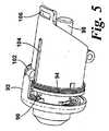
最初に図1から図7を参照すると、本明細書に開示されているランセット切開装置の第1の実施形態が、図1と図2に示されている開位置と図3と図7と図8に示されている閉位置との間を移動するように前方部分12がヒンジ式にその前端部に取り付けられている主胴部分10を有する。この主胴部分10は、駆動機構とコッキングスライダ(cocking slider)とトリガとを含み、一方、前方部分12は、後述するように、ランセットホルダとランセットとを含む。 Referring initially to FIGS. 1-7, a first embodiment of the lancet lancing device disclosed herein is shown in the open position shown in FIGS. 1 and 2, and FIGS. 8 has a
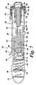
主胴部分10内には、主胴部分10の内壁上にその後端部において固定されている駆動ばね16によって前方に押されているハンマ14がスライド自在に取り付けられている。このハンマ14は主本体部分20と2つの一体状の腕状部22とを有し、この腕状部22の片方が棘状突起付き部分24を有する。腕状部22は、主胴部分の内壁の直径方向に互いに反対側に位置する領域の中に形成されているそれぞれのU字形のガイド26の中に受け入れられる。主胴10の右側は、一体的に形成されているトリガハウジング28を含み、および、V字形ガイド26と連通しているこのトリガハウジング28の基部内には、コッキングスロット(cocked slot)30と前方駆動スロット32とが存在している(図9を参照されたい)。 A
後述するように、ハンマ14がコッキングされると、弾性の腕状部22の棘状突起付き部分24がコッキングスロット30の中にラッチ式に引っ掛かって、ハンマをコッキング位置に保持する。トリガボタン34が2つの棘状突起付き腕状部36によってそのスロット内に係留された状態に保持され、および、コッキングスロット30と位置合わせされているトリガフィンガ38を含む。ハンマ14がコッキングされると、トリガボタン34を押すことが、トリガフィンガ38がコッキングスロット30の中に突き出して棘状突起付き部分24を釈放することを引き起こし、この結果として、ハンマが駆動ばね16の影響を受けて前方に移動するだろう。ハンマが前方に移動するので、その上に棘状突起を有する腕状部22は外側に曲がり、したがって、その棘状突起が前方駆動スロット32の中に入り、および、棘状突起付き部分24がランセットの後部に突き当たり終わった後に、その棘状突起付き部分24が前方駆動スロット21の前端部に突き当たると、ハンマが停止する。コッキングスライド40は、主胴部分10の内壁46のその後端部に作用する戻しばね44によって前方に押される後部スリーブ42を備える。内向きの棘状突起50を有する長方形ストリップ48が後部スリーブ42の前方に延びる。主胴部分内のスロット54を通って外側に突き出すサムピース(thumb piece)52が、ストリップ48の下側に接合させられている。 As will be described later, when the
ハンマ14が発射され終わって、その最前方位置にある時に、コッキングスライド40は後方に引っ張られることができ、その結果として、棘状突起50がトリガの後端部上の突合表面56に係合し、そのトリガをそのコッキング位置に引き戻し、および、ハンマの腕状部22上の棘状突起付き部分24がコッキングスロット30に係合して、トリガボタン34を押すことによって釈放される準備が整っているコッキング位置にハンマを保持する。 When the
可撓性ラッチが、コッキングスライド40から反対側においてケーシング内に取り付けられており、この可撓性ラッチは主本体60とラッチ留め部分62とを備え、このラッチは、ハウジング内の成形凹み66内に受けられている突出部64によってハウジング内に固定されている(図9を参照されたい)。ラッチ留めボタン68が主胴内の穴70を通って突き出る。 A flexible latch is mounted in the casing on the opposite side from the cocking
より詳細に後述する目的のために、2つの腕状部72が主胴部分の前方に延びる。ヒンジ式前方部分12は、主本体部分10に74においてヒンジ式に取り付けられている。この前方部分12は、ランセットホルダ78がスライド移動するように中に取り付けられている内側同軸スリーブ76を支持する(図3および図7)。ランセットホルダは、ランセットホルダの後方移動を制限するために、内側スリーブ76内のめくらキー溝(blind key way)82の中をスライドするばね付き歯(sprung tooth)80を有する。ばね84が、ランセットホルダ78上の外側フランジ86と内側スリーブ76との間で作用する。このばね84は、図7では平衡位置で示されており、および、その次に、ランセットが発射される時にその平衡位置から圧縮する。 For purposes described in more detail below, two
ランセットホルダ78は、ランセットの前端部に係合するための前方に内曲がりしたフランジ88を有する。ハウジングが前方にヒンジ式に動かされる時に、腕状部72の端部がフランジ86の前方に係合し、かつ、フランジ86を前方ハウジングに対して相対的に後方にわずかに引っ張り、さらには、ランセットがホルダ内に装填される時にその前方移動を防止するように、外側に向けられたフランジ86が主胴部分上の前方腕状部72と協働するように設計されている。 The
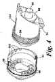
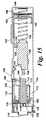
回転可能な鼻状部品92が、前方部分12の前端部上に係留式に取り付けられており、および、圧縮ばね94によってハウジングに対して相対的に後方に押されている。図5と図6とにより明瞭に示されているように、前方ハウジングの前端部は、互いに直径方向に反対側に位置している2つの前向きのV字形突出部96を備えている。これらは、区分壁100によって隔てられている異なる軸方向長さのそれぞれのアバットメント(abutment)98と協働する。この構成が、ばね偏倚力に逆らって鼻状部品92を前方に引っ張ることと、鼻状部品92を所要の位置に向けることと、アバットメント98の厚さによって軸方向位置が決定されるように鼻状部品92を釈放することとによって、前方部分12に対する相対的な鼻状部品92の軸方向位置が調節されることを可能にする。鼻状部品92は、軸位置を表示するノッチ102を含み、および、標識スロット104が前方部分12上に備えられている。主胴部分10と前方部分との合致面が、その装置の縦軸線に対して鋭角の平面にあり、および、ハウジングの前方部分12上の留め具部分106がラッチ留め部分62と協働する。 A
使用時には、ラッチ留めボタン68を押し下げることと、この装置を「2つに折る」ために部分12をヒンジ式に前方に動かすことによって、この装置が開かれる。こうすることによって、ランセットホルダ78上のフランジ86を部分12に対して相対的にわずかに後方に引っ張ってそのフランジ86を前方移動しないように保持するように、腕状部72がフランジ86と協働する。既存のランセット90が引き抜かれて新しいランセットと交換されることが可能であり、および、新しいランセットはその装置の中に前端部から先に挿入される。ランセットホルダの動きを防止する腕状部72は、ランセットが鼻状部品の穴を通して前方に押される可能性を取り除く。その次に、前方部分12がパチンと閉じられる。その次に、駆動ばね16に逆らってハンマ20をそのコッキング位置に引き戻すために、コッキングスライド40が後方に引っ張られ、棘状突起24がコッキングスロット30内に収まる。その次に、ユーザが、鼻状部品12を引っ張って捩って釈放することによって、適切な貫入深さを選択するだろう。このように準備され終わると、ユーザはその装置を自分の皮膚に当てて、トリガボタン34を押す。ハンマ14がランセット90の後部に衝突するように前方に勢いよく飛び出し、ランセット90を瞬時のうちに鼻状部品から突き出して皮膚に穿孔するように駆動する。その後で、ハンマとランセットは図7に示されている平衡位置をとる。 In use, the device is opened by depressing the
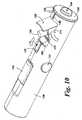
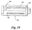
次に図10から図17に示されている第2の実施形態を参照すると、ランセット切開装置は、概ね半円筒形の形状の2つの主ハウジング半分部分120で形成されているハウジングを備え、このハウジングの前端部には、発射時にランセット(図10では見ることができない)の先端が中を通って突き出る穴124を有する鼻状部分122が備えられている。この鼻状部分122の直ぐ後方には、ランセットが装填されるか取り外されることが可能な跳ね上げ式ランセットハッチ128が存在する。この跳ね上げ式のハッチは釈放ボタン130によって釈放される。ランセットはスライダ132によってコッキングされ、および、ランセットは、コッキングされ終わると、トリガボタン134を押すことによって発射される。 Referring now to the second embodiment shown in FIGS. 10-17, the lancet lancing device comprises a housing formed of two
ハウジング120の内側には、ハウジング半分部分の内壁上の互いに反対側に位置する溝140の中を延びる横方向リブ138によって縦方向の移動を阻止されているハンマ136がスライド自在に取り付けられている。このハンマは、ハンマ136の後端部と主ハウジングの末端壁144の内側表面との間に配置されている駆動ばね142によって前方に押されている。ハンマ136の前方移動が、主ハウジングに連結されている停止表面146によって制限されている。コッキングスライダ132から内向きに保護する相補的なアバットメント150と協働するコッキングアバットメント(cocking abutment)148が、ハンマ136の後端部から直立している。コッキングスライダは、外側から到達可能な部分と、ハウジング内の内壁156上に作用する圧縮ばね154によって前方に押されている内側ばね支持リング152とを有する。 Inside the
(前方から見た場合に)左側のハウジング半分部分120は、内向きに移動するようにその中に係留式に取り付けられているトリガボタン134を有する。トリガボタン134は、ハウジング壁内の凹み160に係合させられている棘状突起付き脚部158によって保持されている。棘状突起付き脚部158の相互間には、溝140内に配置されているラッチ留め凹み164と協働する、より短いトリガフィンガ162が存在している。関連した溝140と係合するハンマ136の横方向リブ138が、ハンマをコッキング位置にラッチ留めするためにハンマが後方に引っ張られる時にラッチ留め凹み164内に位置する棘状突起166を有する、弾性的に可撓性の部分を有する形に形成されている。トリガボタン134を押すことが棘状突起166をラッチ留め凹み164の外に押し出し、したがってハンマが駆動ばね142によって前方に駆動される。 The left housing half 120 (when viewed from the front) has a
ランセットハッチ128は、そのハッチがその閉位置にある時に主ハウジングの周囲円筒形表面に形状が一致する上部弓形パネル170を備える。このハッチ128は、このハッチの箱部分172の両側に延びるヒンジ突起部170によってその装置の前端部内に回転自在に取り付けられている。ねじりばね174がハッチを開位置に押して動かす。適切な制動対策が、開き移動の制動を生じさせるために含まれるだろう。箱部分172内には、圧縮ばね178によって後方に押されているが歯179によってその箱部分に係留された状態に保持されているランセットホルダ176が取り付けられている。ランセットホルダ176は、ランセット126が挿入される時にそのランセット126の前方移動を制限するために、そのランセットホルダの内側端部に内向きのリブ181を含む。
図11と図14とに示されているようにランセットホルダがその開位置にある時には、圧縮ばね178は、ランセットホルダを、箱部分172の端部と同一平面であるその最後部位置に自由に押し動かすことができる。ランセット126がホルダに挿入される時には、ハウジングの内壁の一部分を形成する停止表面146と同じ構造の一部分であるラッチ表面が、ランセット126の後端部の移動の円弧の付近に存在している。このラッチ表面180の機能は、ランセット126がハンマ136と位置合わせされている形でハッチが閉じられるまで、ばね178を軽く圧縮するようにランセット126を前方に押し動かすためにランセット126の端部に係合することと、後述するように、ハンマがコッキングされる時に閉じられたハッチをラッチ留めすることである。 When the lancet holder is in its open position, as shown in FIGS. 11 and 14, the
ランセット装填時のそのランセットの前方移動を防止するために、ランセット126/ランセットホルダ176の前方表面と協働するように設計されている弓形支持表面182が、ハウジングの前方下部部分内に存在している。この弓形表面は、ランセット先端を受け入れるためのノッチ184を備える。 An
鼻状部分122が、主ハウジング120の前端部の内側表面内の対応するねじ山付き部分のためにねじ込み式に係合させられており、したがって、ランセットの貫入深さが、鼻状部品が軸方向に出入りするようにその鼻状部品をねじることによって、調節されることが可能である。鼻状部品は、クリック設定(click setting)を可能にするために、ハウジングの内側表面内の戻り止め爪188と係合する直径方向に互いに反対側に位置した腕状部186を有する。標識溝190がハウジング上に備えられており、および、キャップの端部上の異なるサイズのノッチ192が、設定された深さを表示する。 The
使用時には、以前のランセット126が取り外しのために出現するように、そのハッチ128を跳ね上げて開くために釈放ボタン130を後方に引くことによって、ハッチ128が開かれる。ランセットが取り外されて、新しいランセットと交換され、および、ハッチがパチンと閉じられる(図12)。ハンマ136は依然として非コッキング状態であり、その最前方位置にあり、かつ、前方の出っ張り194が停止表面146に突き当たっている。この位置では、ハンマ136の前方表面が傾斜表面180の前方頂点と同一の高さであり、したがって、ばね178は依然として軽く圧縮されており、および、必要に応じてハッチが再び開かれるだろう。ここから、コッキングスライダ132が後方にスライドさせられ、棘状突起166がラッチ凹み164の中に引っ掛かるまでそのコッキングスライダと共にハンマを後方に引っ張る。その次に、このコッキングスライダ132は釈放されて、その当初の位置に戻ることが可能にされる。このプロセス中は、図13に見てとれるように、ランセットが、ばね178の影響を受けて後方に動いて傾斜表面180の下方のそのランセットの阻止位置に戻り、このことがハッチが開くことを防止する(図13)。 In use, the
その次に、ユーザはその装置を自分の皮膚に押し当ててトリガボタン134を押す。ハンマが釈放されて前方に勢いよく飛び出してランセットの後端部に衝突し、ランセットが穴124を通って瞬時のうちに突き出して皮膚に穿孔することを生じさせる。ハンマが、停止表面146に接触する出っ張り194によって止められ、および、ランセットは、短く前進した後に、ばね178の影響を受けてハウジングの中に引っ込み、したがって、これらの構成要素は図12に示されている位置をとる。ハッチは、釈放ボタン130を釈放することによって開かれるだろう。 The user then presses the
第2の実施形態では、ランセットの装填および取り外しの最中にキャップまたはプラットホームが所定の位置に残されているということに留意されたい。このことは、貫入設定に最小限の変動しかないということを意味する。 Note that in the second embodiment, the cap or platform is left in place during loading and unloading of the lancet. This means that there is minimal variation in the intrusion setting.
Claims (18)
Translated fromJapanese主ハウジング(10、120)と、
前記主ハウジング(10、120)にピボット式に連結されており、かつ、閉じた発射位置と、開いた装填/取り外し位置との間を移動可能である係留式ハウジング部分(12、128)と、
該係留式ハウジング部分(12、128)内に設けられたランセットのガイドまたはホルダ(78、176)と、を備え、前記係留式ハウジング部分が、着脱自在なランセット(90、126)の前端部を最初に前記ガイドまたはホルダ(78、176)の中に挿入することを可能にするために開かれることが可能であるように、および、その次に発射の準備のために閉じられるように形状構成されている、ランセット切開装置。A lancet lancing device for use with a removable lancet (90, 126), wherein the lancet is fired so that the lancet protrudes instantaneously from the lancetlancing device to puncture the user's skin. Drive device (44, 142) for causing thelancet lancing device to
A main housing (10, 120);
A mooring housing portion (12, 128) pivotally connected to the main housing (10, 120) and movable between a closed firing position and an open loading / unloading position;
A lancet guide or holder (78, 176) provided in the mooring housing part (12, 128), wherein the mooring housing part defines the front end ofthe removable lancet (90, 126). Shaped so that it can first be opened to allow insertion intosaid guide or holder (78, 176) and then closed in preparation for launch Itis, La Nsetto lancing device.
Applications Claiming Priority (3)
| Application Number | Priority Date | Filing Date | Title |
|---|---|---|---|
| GBGB0715803.3AGB0715803D0 (en) | 2007-08-14 | 2007-08-14 | Lancing devices |
| GB0715803.3 | 2007-08-14 | ||
| PCT/GB2008/002746WO2009022136A1 (en) | 2007-08-14 | 2008-08-14 | Lancing devices |
Publications (2)
| Publication Number | Publication Date |
|---|---|
| JP2010536403A JP2010536403A (en) | 2010-12-02 |
| JP5416108B2true JP5416108B2 (en) | 2014-02-12 |
Family
ID=38566334
Family Applications (1)
| Application Number | Title | Priority Date | Filing Date |
|---|---|---|---|
| JP2010520624AExpired - Fee RelatedJP5416108B2 (en) | 2007-08-14 | 2008-08-14 | Lancet cutting device |
Country Status (5)
| Country | Link |
|---|---|
| US (1) | US9078604B2 (en) |
| EP (1) | EP2187809B1 (en) |
| JP (1) | JP5416108B2 (en) |
| GB (1) | GB0715803D0 (en) |
| WO (1) | WO2009022136A1 (en) |
Families Citing this family (7)
| Publication number | Priority date | Publication date | Assignee | Title |
|---|---|---|---|---|
| US8197503B2 (en) | 2008-08-15 | 2012-06-12 | Abbott Diabetes Care Inc. | Side loading lancing device |
| KR101236410B1 (en)* | 2010-12-15 | 2013-02-22 | 주식회사 아이센스 | Lancet device |
| GB2489740A (en)* | 2011-04-08 | 2012-10-10 | Owen Mumford Ltd | Means for securely retaining a lancet in a lancing device |
| WO2014116688A1 (en) | 2013-01-23 | 2014-07-31 | Facet Technologies, Llc | Push-to-charge lancing device |
| US20180015224A1 (en) | 2016-07-13 | 2018-01-18 | California Institute Of Technology | Dampers and Methods for Performing Measurements in an Autoinjector |
| CN107260185B (en)* | 2017-07-07 | 2023-10-03 | 深圳依洛科特医疗科技有限公司 | Striker self-rebound mechanism for blood collection needle |
| USD939642S1 (en) | 2019-05-01 | 2021-12-28 | ViPR PRO, LLC | Tubular exercise device |
Family Cites Families (14)
| Publication number | Priority date | Publication date | Assignee | Title |
|---|---|---|---|---|
| US4577630A (en)* | 1984-02-14 | 1986-03-25 | Becton, Dickinson And Co. | Reusable breach loading target pressure activated lancet firing device |
| KR0135178Y1 (en) | 1995-06-26 | 1999-03-20 | 김인환 | Blood collection lancet |
| US6027459A (en)* | 1996-12-06 | 2000-02-22 | Abbott Laboratories | Method and apparatus for obtaining blood for diagnostic tests |
| US5964718A (en) | 1997-11-21 | 1999-10-12 | Mercury Diagnostics, Inc. | Body fluid sampling device |
| US6042895A (en) | 1997-12-02 | 2000-03-28 | Huang; Yu-Keng | Method for imprinting woodprints onto blade of fan |
| JP3361470B2 (en)* | 1999-03-02 | 2003-01-07 | アプルス株式会社 | Lancet device for forming precisely controlled incidents |
| GB2388898B (en)* | 2002-04-02 | 2005-10-05 | Inverness Medical Ltd | Integrated sample testing meter |
| JP4484669B2 (en)* | 2003-10-29 | 2010-06-16 | アークレイ株式会社 | Puncture device |
| EP1683483A4 (en) | 2003-10-29 | 2009-07-01 | Arkray Inc | Lancet and centesis instrument |
| US7377904B2 (en)* | 2004-04-16 | 2008-05-27 | Facet Technologies, Llc | Cap displacement mechanism for lancing device and multi-lancet cartridge |
| US20050234486A1 (en) | 2004-04-16 | 2005-10-20 | Allen John J | Apparatus for extracting bodily fluid |
| JP4233496B2 (en)* | 2004-06-17 | 2009-03-04 | テルモ株式会社 | Body fluid testing device |
| GB0427891D0 (en) | 2004-12-21 | 2005-01-19 | Owen Mumford Ltd | Skin pricking apparatus |
| US20060247670A1 (en)* | 2005-05-02 | 2006-11-02 | Levaughn Richard W | Lancing device with automatic lancet release |
- 2007
- 2007-08-14GBGBGB0715803.3Apatent/GB0715803D0/ennot_activeCeased
- 2008
- 2008-08-14EPEP08788315.3Apatent/EP2187809B1/ennot_activeNot-in-force
- 2008-08-14WOPCT/GB2008/002746patent/WO2009022136A1/enactiveApplication Filing
- 2008-08-14USUS12/673,645patent/US9078604B2/enactiveActive
- 2008-08-14JPJP2010520624Apatent/JP5416108B2/ennot_activeExpired - Fee Related
Also Published As
| Publication number | Publication date |
|---|---|
| WO2009022136A1 (en) | 2009-02-19 |
| GB0715803D0 (en) | 2007-09-26 |
| JP2010536403A (en) | 2010-12-02 |
| US9078604B2 (en) | 2015-07-14 |
| EP2187809B1 (en) | 2014-10-01 |
| US20110022070A1 (en) | 2011-01-27 |
| EP2187809A1 (en) | 2010-05-26 |
Similar Documents
| Publication | Publication Date | Title |
|---|---|---|
| JP5416108B2 (en) | Lancet cutting device | |
| EP2187811B1 (en) | Lancing devices | |
| JP5265870B2 (en) | Improved blood sample collection device | |
| KR101791121B1 (en) | Lancet device with lance retraction | |
| US8568434B2 (en) | Lancing device | |
| US5507298A (en) | Forward-fired automatic tissue sampling apparatus | |
| TWI508704B (en) | Prime and fire lancing device with contact bias drive and method | |
| US9282919B2 (en) | Lancet pricking device | |
| EP0115388A1 (en) | Blood sampling instrument | |
| EP1652474A2 (en) | Combined lancing and auxiliary device | |
| JP5969518B2 (en) | Sleeve for detachable lancet of lancing device | |
| AU2003252779A1 (en) | Lancing Device | |
| JP5036711B2 (en) | Lancet assembly and lancing device | |
| JP2003502088A (en) | Lancet assembly | |
| KR101462447B1 (en) | Safety Blood Lancet Device | |
| KR920702970A (en) | Disposable Automatic Soft Tissue Aspiration Biopsy Device | |
| CN108514422B (en) | Blood sampling pen with needle unloading protection | |
| EP2050393A1 (en) | Lancing device | |
| US20090048621A1 (en) | Single-use skin pricking device | |
| JP5420544B2 (en) | Surgical needle device | |
| KR20100008421A (en) | Lancing apparatus | |
| US10905360B2 (en) | Push-to-charge lancing device | |
| KR101511171B1 (en) | Dual cylinder type biopsy device | |
| JP3904722B2 (en) | Tissue resection machine | |
| HK1088805A (en) | Combined lancing and auxiliary device |
Legal Events
| Date | Code | Title | Description |
|---|---|---|---|
| A621 | Written request for application examination | Free format text:JAPANESE INTERMEDIATE CODE: A621 Effective date:20110523 | |
| A977 | Report on retrieval | Free format text:JAPANESE INTERMEDIATE CODE: A971007 Effective date:20130214 | |
| A131 | Notification of reasons for refusal | Free format text:JAPANESE INTERMEDIATE CODE: A131 Effective date:20130402 | |
| A601 | Written request for extension of time | Free format text:JAPANESE INTERMEDIATE CODE: A601 Effective date:20130702 | |
| A602 | Written permission of extension of time | Free format text:JAPANESE INTERMEDIATE CODE: A602 Effective date:20130709 | |
| A521 | Request for written amendment filed | Free format text:JAPANESE INTERMEDIATE CODE: A523 Effective date:20130919 | |
| A01 | Written decision to grant a patent or to grant a registration (utility model) | Free format text:JAPANESE INTERMEDIATE CODE: A01 Effective date:20131015 | |
| A61 | First payment of annual fees (during grant procedure) | Free format text:JAPANESE INTERMEDIATE CODE: A61 Effective date:20131114 | |
| R250 | Receipt of annual fees | Free format text:JAPANESE INTERMEDIATE CODE: R250 | |
| R250 | Receipt of annual fees | Free format text:JAPANESE INTERMEDIATE CODE: R250 | |
| LAPS | Cancellation because of no payment of annual fees |