JP5415913B2 - Hinge unit and portable terminal using the same - Google Patents
Hinge unit and portable terminal using the sameDownload PDFInfo
- Publication number
- JP5415913B2 JP5415913B2JP2009265060AJP2009265060AJP5415913B2JP 5415913 B2JP5415913 B2JP 5415913B2JP 2009265060 AJP2009265060 AJP 2009265060AJP 2009265060 AJP2009265060 AJP 2009265060AJP 5415913 B2JP5415913 B2JP 5415913B2
- Authority
- JP
- Japan
- Prior art keywords
- shaft
- cam
- flange
- hinge
- elastic member
- Prior art date
- Legal status (The legal status is an assumption and is not a legal conclusion. Google has not performed a legal analysis and makes no representation as to the accuracy of the status listed.)
- Expired - Fee Related
Links
- 230000007246mechanismEffects0.000description29
- 230000002093peripheral effectEffects0.000description2
- 230000005540biological transmissionEffects0.000description1
- 230000006835compressionEffects0.000description1
- 238000007906compressionMethods0.000description1
- 238000010586diagramMethods0.000description1
- 230000000694effectsEffects0.000description1
- 239000004973liquid crystal related substanceSubstances0.000description1
- 230000001105regulatory effectEffects0.000description1
- 239000011347resinSubstances0.000description1
- 229920005989resinPolymers0.000description1
- 238000000926separation methodMethods0.000description1
Images


Landscapes
- Pivots And Pivotal Connections (AREA)
- Telephone Set Structure (AREA)
Description
Translated fromJapanese本発明は、ヒンジユニット及びそれを用いた携帯端末に関する。 The present invention relates to a hinge unit and a portable terminal using the hinge unit.
液晶装置等の表示デバイスが内設された表示筐体をテンキー等の入力デバイスが設けられた操作筐体に対して回動可能に設けた携帯端末が知られている。このような表示筐体を操作筐体に対して、回動可能にする機構はヒンジ機構と呼称され、表示筐体を1軸の回りに回動可能にする1軸ヒンジや、互いに直交する2軸の回りにそれぞれ独立に回動可能にする2軸ヒンジが知られている。 There is known a portable terminal in which a display housing in which a display device such as a liquid crystal device is provided is rotatable with respect to an operation housing provided with an input device such as a numeric keypad. Such a mechanism that allows the display housing to rotate with respect to the operation housing is called a hinge mechanism, and includes a single-axis hinge that enables the display housing to rotate about one axis, and two orthogonal to each other. 2. Description of the Related Art Two-axis hinges that can be independently rotated around an axis are known.
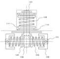
このようなヒンジ機構は、例えば特許文献1〜4に開示されている。特許文献1が開示するヒンジ機構は、図8に示すように、開閉軸101および回転軸107を有する2軸ヒンジである。そして、開閉軸101には開閉軸用の回転カム105が配置され、この開閉軸用回転カム105の両側からコイルバネ103が圧接することにより、摩擦力を発生させている。また、回転軸107には回転軸用の回転カム111と固定カム110とがバネ109により圧接されることにより、摩擦力を発生させている。従って、この摩擦力により回転軸107の自由回転が規制される。 Such a hinge mechanism is disclosed in Patent Documents 1 to 4, for example. The hinge mechanism disclosed in Patent Document 1 is a biaxial hinge having an opening /
また、特許文献2が開示するヒンジ機構は、図9に示すように、回動部203や係合突部205を備えている。回動部203は、係合凹部204を備えて回動する。係合突部205は、弾性部材206により回動部203に押圧されている。これにより、弾性部材206により押圧された係合突部205が係合凹部204に嵌ることにより、回転時にクリック感を発生させながら回動部203の自由回動が規制される。 Further, the hinge mechanism disclosed in Patent Document 2 includes a
また、特許文献3が開示するヒンジ機構は、図10に示すように、凹凸カム303、矩形カム307、伸張バネ306を備えている。凹凸カム303は、第1軸部材302の一端に設けられている。矩形カム307は、第2軸部材308側に設けられ、凹凸カム303面の上に当接する。伸張バネ306は、凹凸カム303を矩形カム307側に押圧する。そして、四角形状の矩形カム307の頂点が凹凸カム303を通過する際に生じる回転力の急激な変動により、回転時にクリック感を発生させながら矩形カム307の自由回動が規制される。 Further, the hinge mechanism disclosed in
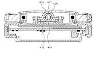
さらに、特許文献4が開示するヒンジ機構は、図11に示すように、回転軸406の外周に平面407を形成すると共に、軸受ホルダー419で回転軸406を支持し、板バネ422で回転軸406を軸受ホルダー419側に押圧している。これにより、板バネ422が平面407に当接した状態と離接した状態とで、回転軸406を回転させるための力に変化が生じて、回転時にクリック感を発生させながら回転軸406の自由回転が規制される。 Further, as shown in FIG. 11, the hinge mechanism disclosed in
しかしながら、上記各特許文献1〜4にかかるヒンジ機構では、カムの作用点K1とバネの作用点K2との距離が近接しているため、明確なクリック感を得るためには強いバネ力のバネ等を用いる必要があった。 However, in the hinge mechanisms according to Patent Documents 1 to 4, since the distance between the cam action point K1 and the spring action point K2 is close, a spring with a strong spring force is required to obtain a clear click feeling. Etc. had to be used.
例えば特許文献1にかかるヒンジ機構では、固定カム110や回転カム111は円盤状に形成され、かつ、これら固定カム110等のカム軸とバネ(コイルバネ)のコイル軸とは同軸に配置されているため、大きなバネ力のバネを用いると、固定カム110等が撓みながらカム部の係合・離合が行われるようになる。固定カム110等が撓むことは、バネ力が撓みにより吸収されることを意味するので、バネ力は有効利用されない。従って、固定カム110等の厚みを厚くしなければならず、カム機構の大型化を招く問題が生じる。また、バネ力を大きくすると、回転カム111と固定カム110との圧接力が増大し、回転カム111と固定カム110との摩擦面の摩耗が増大する。 For example, in the hinge mechanism according to Patent Document 1, the
また、特許文献2にかかるヒンジ機構は、針金状の弾性部材206の先端部分に設けられた係合突起205が回動部203の係合凹部204に係合・離合する。左右の係合突起205は1つの弾性部材206により回動自在に支持されているため、係合突起205と係合凹部204とが係合・離合する際には、弾性部材206が全長に渡り変形する。従って、確かな係合状態を得るためにはバネ力を大きくしなければならない。なお、回動部203が回動している最中は、係合突起205がローラ等により形成されているので、略自由回動の状態となってしまう。このため、係合突起205が係合凹部204に係合し始めると、バネ力により係合突起205は係合凹部204に急に落ち込む。この急激な落ち込みは、バネ力が大きいほど大きくなり、ユーザに違和感を与えてしまう不都合がある。 Further, in the hinge mechanism according to Patent Document 2, the
また、特許文献3にかかるヒンジ機構は、矩形カム307の回転に伴い伸張バネ306のバネ力に抗して第1軸部材302が矩形カム307に向かい進退することによりクリック感を得る。しかし、この構成では矩形カム307は微少角の範囲内であれば容易に回動できるため、明確なクリック感を得ることが難しい。即ち、矩形カム307が角度θだけ回転したとすると、第1軸部材302はsin(θ)だけ進退することになる。この回転角度θが微少であれば、sin(θ)は略「0」と近似できる(sin(θ)≒0)。従って、伸張バネ306によっては第1軸部材302の微少角の回転を規制することが困難であることを示している。このことは、ヒンジ機構にガタツキが生まれることを意味し、ユーザにクリック感の非シャープさ等を与える。そこで、伸張バネ306のバネ力を大きくして上記微少角の範囲を小さくすることが考えられるが、この場合は、矩形カム307を「90度」回転させる際に要する力が大きくなり、操作性が損なわれる問題が生じる。 Further, the hinge mechanism according to
さらに、特許文献4にかかるヒンジ機構は、回転軸406に板バネ422が当接し、この回転軸406の平面407に当接したとき係合状態となることでクリック感を得ている。しかし、この場合も、明確なクリック感を得るためには板バネ422のバネ力を強くしなければならず、かつ、平面407の面積を大きくしなければならない。なお、この平面407の面積は、回転軸406の回転を規制する際に、板バネ422が接する面積である。平面407の面積を大きくすることは、回転軸406が円筒状に形成されているので、平面407の部分の肉厚が薄くなることを意味し、強度低下を招く要因となる。 Furthermore, the hinge mechanism according to
そこで、本発明の主目的は、弾性部材の弾性力を大きくすることなく、カムの係合・離合によるガタツキ等の発生を防止しながら確かなクリック感が得られるヒンジユニット及び携帯端末を提供することである。 SUMMARY OF THE INVENTION Accordingly, a main object of the present invention is to provide a hinge unit and a portable terminal capable of obtaining a certain click feeling while preventing the occurrence of rattling or the like due to engagement / disengagement of a cam without increasing the elastic force of an elastic member. That is.
上記課題を解決するため、本発明にかかるヒンジユニットは、ヒンジ軸をなすシャフトと、シャフトが回動自在に挿通するフランジと、係合部を備えて、シャフトが回動自在に挿通する固定カムと、係合部と係合する被係合部を備えて、シャフトの回動に従動する可動カムと、フランジと固定カムとの間に配置され、かつ、ヒンジ軸から所定量離れた位置に配置されて、固定カムを可動カムの方向に押圧する弾性部材と、を備え、弾性部材が、ヒンジ軸の左右のいずれか一方の側に設けられ、固定カムの一端が、フランジのフランジ面に回動自在に支持され、他端が弾性部材により可動カムの方向に押圧されていることを特徴とする。In order to solve the above problems, a hinge unit according to the present invention includes a shaft that forms a hinge shaft, a flange through which the shaft is rotatably inserted, and an engaging portion, and a fixed cam through which the shaft is rotatably inserted. And an engaged portion that engages with the engaging portion, and is disposed between the movable cam that follows the rotation of the shaft, the flange, and the fixed cam, and at a position away from the hinge shaft by a predetermined amount. And an elastic member that presses the fixed cam in the direction of the movable cam, andthe elastic member is provided on either the left or right side of the hinge shaft, and one end of the fixed cam is on the flange surface of the flange. The other end is pressed in the direction of the movable cam by an elastic member .
また、携帯端末は、表示デバイスが内設された第1の筐体と、入力デバイスが設けられた第2の筐体と、第1の筐体と第2の筐体を連結するヒンジユニットと、を備え、 ヒンジユニットが、ヒンジ軸をなすシャフトと、シャフトが回動自在に挿通するフランジと、係合部を備えてシャフトが回動自在に挿通する固定カムと、係合部と係合する被係合部を備えてシャフトの回動に従動する可動カムと、フランジと固定カムとの間に配置され、かつ、ヒンジ軸から所定量離れた位置に配置されて、固定カムを可動カムの方向に押圧する弾性部材と、を備え、弾性部材が、ヒンジ軸の左右のいずれか一方の側に設けられ、固定カムの一端が、フランジのフランジ面に回動自在に支持され、他端が弾性部材により可動カムの方向に押圧されていることを特徴とする。
In addition, the mobile terminal includes a first housing in which a display device is installed, a second housing in which an input device is provided, and a hinge unit that connects the first housing and the second housing. The hinge unit includes a shaft forming a hinge shaft, a flange through which the shaft is rotatably inserted, a fixed cam through which the shaft is rotatably inserted, and an engagement with the engagement portion. A movable cam that includes an engaged portion that follows the rotation of the shaft, and is disposed between the flange and the fixed cam, and is disposed at a position separated from the hinge shaft by a predetermined amount. An elastic member that presses in the direction of the elastic member, theelastic member is provided on either the left or right side of the hinge shaft, one end of the fixed cam is rotatably supported on the flange surface of the flange, and the other end Is pressed in the direction of the movable cam by the elastic member It is characterized by .
本発明によれば、弾性部材の弾性力を大きくすることなく、カムの係合・離合によるガタツキ等の発生を防止しながら確かなクリック感が得られる。 According to the present invention, a reliable click feeling can be obtained without increasing the elastic force of the elastic member and preventing the occurrence of rattling due to engagement / disengagement of the cam.
<第1の実施形態>
本発明の第1の実施形態を図を参照して説明する。図1は、第1の実施形態にかかるヒンジユニットの部分上面図である。ヒンジユニット1は、シャフト2、フランジ3、固定カム4、可動カム5、弾性部材6等を備える。シャフト2は、ヒンジユニット1のヒンジ軸をなす。フランジ3は、シャフト2に回動自在に挿通されている。固定カム4は、係合部7を備えて、シャフト2に回動自在に挿通されている。可動カム5は、係合部7と係合する被係合部8を備えてシャフト2の回動に従動する。弾性部材6は、フランジ3と固定カム4との間であって、ヒンジ軸から所定量離れた位置に配置されて、固定カム4を押圧している。<First Embodiment>
A first embodiment of the present invention will be described with reference to the drawings. FIG. 1 is a partial top view of the hinge unit according to the first embodiment. The hinge unit 1 includes a shaft 2, a
これにより、ヒンジ軸から所定量離れた弾性部材が大きな弾性力を持たない場合であっても、この距離に比例するモーメントにより大きな力が係合部と被係合部とに作用する。よって、リンク機構にガタツキ等が発生するのを防止し、かつ、確かなクリック感を得ながら係合・離合が行えるヒンジユニットが提供できるようになる。
<第2の実施形態>
本発明の第2の実施形態を図を参照して説明する。図2は、第2の実施形態にかかるヒンジユニットを適用した携帯端末の斜視図である。なお、以下の説明では、携帯端末として携帯電話を例に説明するが、PHS(Personal Handy−phone System)等の端末であっても良い。Thereby, even when the elastic member separated from the hinge shaft by a predetermined amount does not have a large elastic force, a large force acts on the engaging portion and the engaged portion due to a moment proportional to the distance. Therefore, it is possible to provide a hinge unit that can prevent rattling or the like from occurring in the link mechanism and that can be engaged / disengaged while obtaining a certain click feeling.
<Second Embodiment>
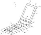
A second embodiment of the present invention will be described with reference to the drawings. FIG. 2 is a perspective view of a portable terminal to which the hinge unit according to the second embodiment is applied. In the following description, a mobile phone is described as an example of the mobile terminal, but a terminal such as a PHS (Personal Handy-phone System) may be used.
携帯端末10は、表示デバイス11を内設する表示筐体12、操作筐体13、ヒンジユニット14を備え、ヒンジユニット14が表示筐体12と操作筐体13とを回動自在に連結している。 The
ヒンジユニット14は、以下のように、表示筐体(第1の筐体)12と操作筐体(第2の筐体)13とを2軸で回動可能に連結する。即ち、ヒンジユニット14は、表示筐体12の長手方向に延びる軸線(以下、X軸線と記載する)と、このX軸線に直交し、携帯端末10の幅方向に沿う軸線(以下、Y軸線と記載する)との2つの回動軸からなる2軸ヒンジ機構を持つ。以下、X軸を反転軸、Y軸を開閉軸と記載する。そして、表示筐体12が反転軸の回りに回動する動作を反転動作、開閉軸の回りに回動する動作を開閉動作と記載する。 The
操作筐体13の内部には、各種の情報の送受信等に必要な電子機器が配置されると共に、各種の情報入力に用いられるテンキー等の入力デバイス19が操作筐体13の操作面15に設けられている。操作筐体13における操作面15の先端部(ヒンジユニット14から最も遠い端部領域)には、パッド20が設けられている。 An electronic device necessary for transmission / reception of various types of information is arranged inside the
このパッド20は、樹脂やゴム等の弾性体から形成され、携帯端末10を閉状態にしたときに、表示筐体12がパッド20に当接することにより、表示筐体12と操作筐体13との間に所定のクリアランスを確保する。 The
そして、表示筐体12が開閉軸の回りに回動することにより、携帯端末10の開閉が行われる。また、携帯端末10を閉状態にしたとき、携帯端末10は、表示筐体12の反転状態に応じて表示筐体正面17が操作面15に対面する状態と表示筐体裏面18が操作面15に対面する状態とをとる。 Then, the
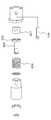
図3は、ヒンジユニット14の構成を示す斜視図である。また、図4は、このヒンジユニット14の分解斜視図である。ヒンジユニット14の一端には操作筐体側ヒンジ部30が設けられ、他端には表示筐体側ヒンジ部40が設けられている。操作筐体側ヒンジ部30は、操作筐体13に対してヒンジユニット14を開閉軸(Y軸)の周りに回動可能に支持するための支持軸穴31を備える。 FIG. 3 is a perspective view showing the configuration of the
表示筐体側ヒンジ部40は、第1フランジ41、第2フランジ(フランジ)42、シャフト43、カム機構50を備える。第1フランジ41は、操作筐体側ヒンジ部30にネジ等により固定される。第2フランジ42は、表示筐体12にネジ等により固定される。シャフト43は、一端が第1フランジ41に固着され、他端が第2フランジに42に挿通して、第2フランジ42を第1フランジ41に対して回動自在に支持する。カム機構50は、第2フランジ42の自由回動を規制しながら、この第2フランジ42が所定位置に止まるように規制する。 The display housing side hinge 40 includes a
カム機構50は、板バネ、皿バネ、コイルバネ等の弾性部材51、固定カム52、可動カム53、カム止リング54、固定カム支持ピン55を備える。 The
なお、シャフト43における第2フランジ42側の端部領域には、カム止リング54が係合する係合溝56が、形成されると共に、面取部57が形成されている。以下、このシャフト43の端部領域を、シャフト先端領域65と記載する。 In the end region of the
また、固定カム52は略矩形状に形成され、その中央部分に凹状のカム収納部61が形成されると共に、シャフト43が挿通するシャフト穴59が形成されている。 Further, the fixed
なお、このシャフト穴59の周縁面(カム面)62には、2つの係合部60が対向して形成されている。この係合部60の形状は、後述する図5に示すように等脚台形状になっている。さらに、固定カム52の左右端部領域には、固定カム支持ピン55の挿通するピン穴58が形成されている。 Two
可動カム53は、概略円筒体で、中央にシャフト先端領域65が嵌合するシャフト係合穴63が形成されると共に、カム面62と対向する周端面に係合部60と係合する被係合部64が形成されている。被係合部64は、図5に示すように係合部60と同一形状を持っている。 The
なお、係合部60は凸形状で2つ設けられ、被係合部64は凹形状で2つ設けられている場合について説明するが、本実施形態はこれに限定されない。即ち、凹形状の被係合部64(又は係合部60)の数N1が、凸形状の係合部60(又は被係合部64)の数N2より多ければよい(N1≧N2)。このとき係合部60及び被係合部64の数は、偶数で、かつ、反転軸(X軸)に対称に形成されていることが好ましい。これは、可動カム53が反転軸の軸心に対して対称に回動できるようにするためである。可動カム53が回転軸の軸心に対して対称に回動すると、滑らかな回動が可能になる。また、係合部60と被係合部64を複数設けた場合に、係合部60と被係合部64との片当たりを防止することができる。即ち、複数の係合部60が、それぞれ対応する被係合部64と同時に係合・離合することができる。従って、片当たりによる部分的な摩耗が抑制できる。 In addition, although the case where two engaging
また、係合部60が凹形状で、被係合部64が凸形状であっても良い。さらに、係合部60や被係合部64の形状は三角形や半円形状等が可能である。 Further, the engaging
このようなヒンジユニット14は、以下のようにして組み立てられる。先ず、第1フランジ41に立設されたシャフト43に第2フランジ42を挿通し、第2フランジ42に立設された左右の固定カム支持ピン55に弾性部材51を挿通する。そして、固定カム52のシャフト穴59にシャフト43を挿通すると共に、ピン穴58に固定カム支持ピン55を挿通する。その後、可動カム53のシャフト係合穴63をシャフト43に挿通する。 Such a
シャフト先端領域65には面取部57が形成され、シャフト係合穴63には面取部57に対応した回転規制面63aが形成されているので、シャフト係合穴63をシャフト43に挿通することにより、可動カム53はシャフト43に従って回動するようになる。そして、固定カム52を第2フランジ42側に押して弾性部材51を収縮させ、カム止リング54を係合溝56に係合させる。これにより、可動カム53をシャフト43に取り付けることができる。 A chamfered
次に、このヒンジユニット14の動作を図5を参照して説明する。図5(a)は係合部60と被係合部64とが係合した状態を示すヒンジユニット14の上面図であり、図5(b)は係合部60と被係合部64とが離合した状態を示すヒンジユニット14の上面図である。 Next, the operation of the
図5(a)に示すように、係合部60と被係合部64とが係合した状態では、弾性部材51は略自由長(圧縮も伸張もしていない状態)となっている。この状態から第2フランジ42を図5(b)に示す矢印D1の方向に回転させて、被係合部64と係合部60とを離合させる。係合部60等は所定の高さHを持つため、被係合部64と係合部60との係合を解除させるためには、固定カム52は矢印D2の方向に寸法Hだけ移動しなければならない。 As shown in FIG. 5A, in a state where the engaging
可動カム53の作用点をP1、第2フランジ42の作用点をP2、作用点をP1と作用点をP2との距離をLとすると、作用点P1に働く力F1に釣り合う力は、作用点P2に働く力F2のL/2倍となる(F1=F2。L/2)。即ち、作用点P1と作用点P2とが距離Lだけ離れているため、弾性部材51の弾性力が小さくても、大きな力を作用点P1に作用させることが可能になる。従って、弾性部材の弾性力を大きくすることなくカム機構の係合・離合が確実に行えるので、表示筐体を回転運動させた際には明確なクリック感が得られる。また、係合部60と被係合部64とが離合して、係合部60と被係合部64とが当接しながら可動カム53が回動する際には、当接部に摩擦力が働くので、リンク機構にガタツキが発生することはない。 If the action point of the
特に、図6に示すように、シャフト43と同軸にコイルバネ68を設け、かつ、そのコイルバネ68の半径が上記の距離Lに相当させるならば、特許文献1に示した構成に近似するが、この場合はコイルバネ68が表示筐体12からはみ出してしまう不都合が生じる。近年、表示筐体等の小型・薄型化が進んでいるため、表示筐体12からコイルバネ68が容易にはみ出してしまう。なお、図6は、半径の大きなコイルバネの使用を弾性部材として用いた場合のヒンジユニットの正面図である。 In particular, as shown in FIG. 6, if a
しかし、本実施形態のように可動カム53の左右に弾性部材51を配置することにより、小さな弾性力の弾性部材51であっても、モーメントにより拡大された大きな力が係合部60と被係合部64とに作用する。従って、厚みの薄い携帯端末に適用された場合であっても、意匠性を損なうことなく確実に表示筐体の回転規制ができると共に、明確なクリック感が得られるようになる。
<第3の実施形態>
次に、本発明の第3の実施形態を図を参照して説明する。なお、第2の実施形態と同一構成に関しては同一符号を用いて説明を適宜省略する。However, by disposing the
<Third Embodiment>
Next, a third embodiment of the present invention will be described with reference to the drawings. In addition, about the same structure as 2nd Embodiment, description is abbreviate | omitted suitably using the same code | symbol.
第2の実施形態においては、固定カムは、その左右の端部において弾性部材から弾性力により押圧する構造であった。これに対して、第3の実施形態にかかる固定カムは、一方の端部は第2フランジ42に回動自在に支持され、他方の端部は弾性部材から弾性力を受ける構成である。 In the second embodiment, the fixed cam has a structure in which the left and right ends thereof are pressed by an elastic force from the elastic member. On the other hand, the fixed cam according to the third embodiment is configured such that one end is rotatably supported by the
図7は、このようなヒンジユニット14Bの上面図である。固定カム70は、概略L字状に形成され、一端は弾性部材51により押圧されている。また、固定カム70の他端は、支持板71に挿通された支持軸72により回動自在に支持されている。 FIG. 7 is a top view of such a
このような構成により、固定カム70の係合部60と可動カム53の被係合部64とが係合・離合する。係合力は係合部60の作用点と、弾性部材の作用点をL2としたとき、弾性部材51の発生する力のL2倍となる。従って、弾性部材51の弾性力を大きくすることなくカム機構の係合・離合が確実に行えるので、表示筐体12を反転運動させた際には明確なクリック感が得られる。 With such a configuration, the engaging
1、14,14B ヒンジユニット
2,43 シャフト
3 フランジ
4,52,70 固定カム
5,53 可動カム
6,50 弾性部材
7,60 係合部
8,64 被係合部
10 携帯端末
11 表示デバイス
12 表示筐体
13 操作筐体
41 第1フランジ
42 第2フランジ
50 カム機構
61 カム収納部DESCRIPTION OF
Claims (2)
Translated fromJapanese前記シャフトが回動自在に挿通するフランジと、
係合部を備えて、前記シャフトが回動自在に挿通する固定カムと、
前記係合部と係合する被係合部を備えて、前記シャフトの回動に従動する可動カムと、
前記フランジと前記固定カムとの間に配置され、かつ、前記ヒンジ軸から所定量離れた位置に配置されて、前記固定カムを前記可動カムの方向に押圧する弾性部材と、を備え、
前記弾性部材が、前記ヒンジ軸の左右のいずれか一方の側に設けられ、
前記固定カムの一端が、前記フランジのフランジ面に回動自在に支持され、他端が前記弾性部材により前記可動カムの方向に押圧されていることを特徴とするヒンジユニット。A shaft forming a hinge axis;
A flange through which the shaft is rotatably inserted;
A fixed cam having an engaging portion, through which the shaft is rotatably inserted;
A movable cam that includes an engaged portion that engages with the engaging portion, and that follows the rotation of the shaft;
An elastic member disposed between the flange and the fixed cam and disposed at a position away from the hinge shaft by a predetermined amount to press the fixed cam in the direction of the movable cam;
The elastic member is provided on either the left or right side of the hinge shaft;
One end of the fixed cam is rotatably supported on a flange surface of the flange, and the other end is pressed in the direction of the movable cam by the elastic member .
入力デバイスが設けられた第2の筐体と、
前記第1の筐体と前記第2の筐体を連結するヒンジユニットと、を備え、
前記ヒンジユニットが、ヒンジ軸をなすシャフトと、前記シャフトが回動自在に挿通するフランジと、係合部を備えて前記シャフトが回動自在に挿通する固定カムと、前記係合部と係合する被係合部を備えて前記シャフトの回動に従動する可動カムと、前記フランジと前記固定カムとの間に配置され、かつ、前記ヒンジ軸から所定量離れた位置に配置されて、前記固定カムを前記可動カムの方向に押圧する弾性部材と、を備え、
前記弾性部材が、前記ヒンジ軸の左右のいずれか一方の側に設けられ、
前記固定カムの一端が、前記フランジのフランジ面に回動自在に支持され、他端が前記弾性部材により前記可動カムの方向に押圧されていることを特徴とする携帯端末。A first housing in which a display device is installed;
A second housing provided with an input device;
A hinge unit that connects the first housing and the second housing;
The hinge unit includes a shaft forming a hinge shaft, a flange through which the shaft is rotatably inserted, a fixed cam through which the shaft is rotatably inserted, and an engagement with the engagement portion. A movable cam that includes an engaged portion that follows the rotation of the shaft, and is disposed between the flange and the fixed cam, and is disposed at a position separated from the hinge shaft by a predetermined amount, An elastic member that presses the fixed cam in the direction of the movable cam,
The elastic member is provided on either the left or right side of the hinge shaft;
One end of the fixed cam is rotatably supported on a flange surface of the flange, and the other end is pressed in the direction of the movable cam by the elastic member .
Priority Applications (1)
| Application Number | Priority Date | Filing Date | Title |
|---|---|---|---|
| JP2009265060AJP5415913B2 (en) | 2009-11-20 | 2009-11-20 | Hinge unit and portable terminal using the same |
Applications Claiming Priority (1)
| Application Number | Priority Date | Filing Date | Title |
|---|---|---|---|
| JP2009265060AJP5415913B2 (en) | 2009-11-20 | 2009-11-20 | Hinge unit and portable terminal using the same |
Related Child Applications (1)
| Application Number | Title | Priority Date | Filing Date |
|---|---|---|---|
| JP2013128304ADivisionJP5512866B2 (en) | 2013-06-19 | 2013-06-19 | Hinge unit and portable terminal using the same |
Publications (2)
| Publication Number | Publication Date |
|---|---|
| JP2011106642A JP2011106642A (en) | 2011-06-02 |
| JP5415913B2true JP5415913B2 (en) | 2014-02-12 |
Family
ID=44230328
Family Applications (1)
| Application Number | Title | Priority Date | Filing Date |
|---|---|---|---|
| JP2009265060AExpired - Fee RelatedJP5415913B2 (en) | 2009-11-20 | 2009-11-20 | Hinge unit and portable terminal using the same |
Country Status (1)
| Country | Link |
|---|---|
| JP (1) | JP5415913B2 (en) |
Families Citing this family (1)
| Publication number | Priority date | Publication date | Assignee | Title |
|---|---|---|---|---|
| CN114135566A (en)* | 2020-09-03 | 2022-03-04 | 华为技术有限公司 | Rotary shaft assembly and storage box |
Family Cites Families (4)
| Publication number | Priority date | Publication date | Assignee | Title |
|---|---|---|---|---|
| JP3662353B2 (en)* | 1996-08-05 | 2005-06-22 | 加藤電機株式会社 | Tilt hinge |
| JP2005009602A (en)* | 2003-06-19 | 2005-01-13 | Nippon Chemicon Corp | Hinge device |
| JP4625321B2 (en)* | 2004-12-13 | 2011-02-02 | 加藤電機株式会社 | Hinge device for mobile device and mobile phone |
| JP4655680B2 (en)* | 2005-03-01 | 2011-03-23 | 日本電気株式会社 | Biaxial hinge mechanism and portable communication terminal using the same |
- 2009
- 2009-11-20JPJP2009265060Apatent/JP5415913B2/ennot_activeExpired - Fee Related
Also Published As
| Publication number | Publication date |
|---|---|
| JP2011106642A (en) | 2011-06-02 |
Similar Documents
| Publication | Publication Date | Title |
|---|---|---|
| EP2546719B1 (en) | Hinge for electronic device | |
| CN100435607C (en) | Hinge device and electronic equipment using the same | |
| JP4731539B2 (en) | Hinge mechanism | |
| EP2615331B1 (en) | Opening/closing device | |
| JP5661817B2 (en) | Hinge device | |
| WO2011145458A1 (en) | Opening/closing device | |
| JPH10319856A (en) | Opening/closing device for opening/closing body | |
| WO2012039360A1 (en) | Cover mechanism for opening and closing device | |
| JP4625424B2 (en) | Hinge device and portable device | |
| CN113330826A (en) | Hinge assembly | |
| JP2012211606A (en) | Hinge device, opening/closing device, and portable equipment | |
| JP4591397B2 (en) | HINGE DEVICE AND DEVICE HAVING HINGE DEVICE | |
| US20110102982A1 (en) | Electronic apparatus | |
| JP2001227229A (en) | Biaxial hinge device | |
| JP5991928B2 (en) | Switchgear | |
| JP4397225B2 (en) | Hinge device | |
| JP2017181598A (en) | Hinge and office machine having the same | |
| JP5415913B2 (en) | Hinge unit and portable terminal using the same | |
| US20110127184A1 (en) | Electronic apparatus with hinge mechanism | |
| CN112214068A (en) | Linkage mechanism and electronic device | |
| JP5512866B2 (en) | Hinge unit and portable terminal using the same | |
| JP2012211629A (en) | Tilt hinge, and electronic apparatus with the same | |
| JP6497771B2 (en) | Tilt hinge and electronic device | |
| JP5598776B2 (en) | Hinge device | |
| CN116677699B (en) | Electronic device, rotation module and shaft structure |
Legal Events
| Date | Code | Title | Description |
|---|---|---|---|
| RD01 | Notification of change of attorney | Free format text:JAPANESE INTERMEDIATE CODE: A7421 Effective date:20110713 | |
| A621 | Written request for application examination | Free format text:JAPANESE INTERMEDIATE CODE: A621 Effective date:20121018 | |
| A977 | Report on retrieval | Free format text:JAPANESE INTERMEDIATE CODE: A971007 Effective date:20130430 | |
| A131 | Notification of reasons for refusal | Free format text:JAPANESE INTERMEDIATE CODE: A131 Effective date:20130507 | |
| A521 | Written amendment | Free format text:JAPANESE INTERMEDIATE CODE: A523 Effective date:20130619 | |
| A01 | Written decision to grant a patent or to grant a registration (utility model) | Free format text:JAPANESE INTERMEDIATE CODE: A01 Effective date:20131022 | |
| A61 | First payment of annual fees (during grant procedure) | Free format text:JAPANESE INTERMEDIATE CODE: A61 Effective date:20131114 | |
| S111 | Request for change of ownership or part of ownership | Free format text:JAPANESE INTERMEDIATE CODE: R313115 | |
| R350 | Written notification of registration of transfer | Free format text:JAPANESE INTERMEDIATE CODE: R350 | |
| LAPS | Cancellation because of no payment of annual fees |